


Languages
Pages
Legal


Loughborough UniversityInstitutional Repository
Parametric 3D modelling ofnonwovens for mechanicaland filtration properties
This item was submitted to Loughborough University's Institutional Repositoryby the/an author.
Citation: SOZUMERT, E. ... et al, 2016. Parametric 3D modelling of nonwo-vens for mechanical and filtration properties. Presented at: Oil, Gas and Chem-icals Filtration and Separations Conference-Expo, 9th-11th May 2016, Houston,Texas, USA.
Additional Information:
• This is a conference presentation.
Metadata Record: https://dspace.lboro.ac.uk/2134/21661
Version: Accepted for publication
Rights: This work is made available according to the conditions of the Cre-ative Commons Attribution-NonCommercial-NoDerivatives 4.0 International(CC BY-NC-ND 4.0) licence. Full details of this licence are available at:https://creativecommons.org/licenses/by-nc-nd/4.0/
Please cite the published version.

1
Parametric 3D Modelling of Nonwovens for
Mechanical and Filtration Properties
Emrah Sozumert1, Emrah Demirci1, Martin J. Lehmann2 ,
Memis Acar1, V. Vadim Silberschmidt1
1Wolfson School of Mechanical, Electrical and Manufacturing Engineering,
Loughborough University, Leicestershire, UK 2Simulation Filter Elements, MANN+HUMMEL GmbH, Ludwigsburg, Germany
2
Motivation
**http://www.nonwovens-industry.com/ *a2zbabybabydiapers.wordpress.com
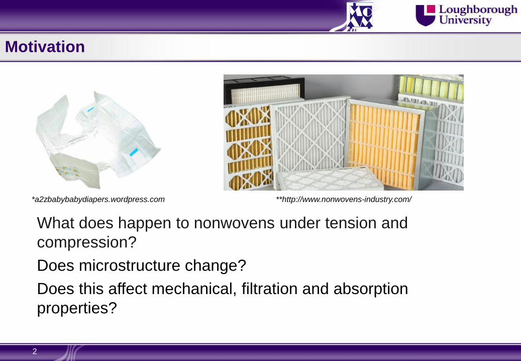
What does happen to nonwovens under tension and
compression?
Does microstructure change?
Does this affect mechanical, filtration and absorption
properties?

3
Outline
Motivation
Objectives
Material and microstructure
Experiments
Tensile Performance
Out-of-plane Loading
A New Parametric 3D Computational Model
Flow Simulations
Summary and conclusions
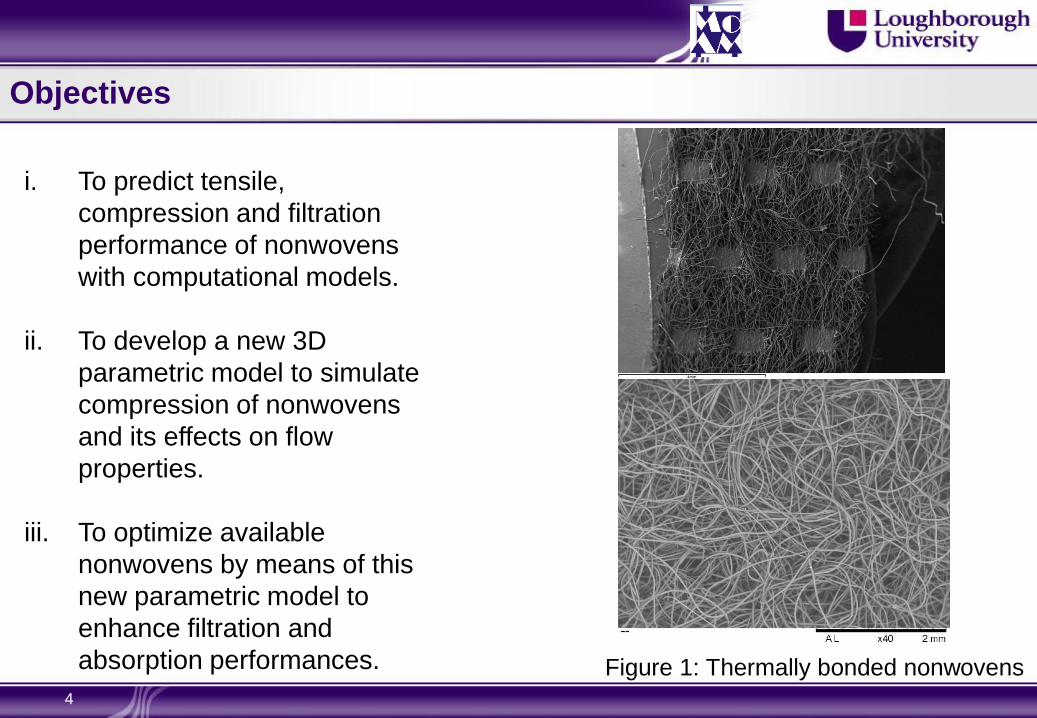
i. To predict tensile,
compression and filtration
performance of nonwovens
with computational models.
ii. To develop a new 3D
parametric model to simulate
compression of nonwovens
and its effects on flow
properties.
iii. To optimize available
nonwovens by means of this
new parametric model to
enhance filtration and
absorption performances.
4
Figure 1: Thermally bonded nonwovens
Objectives

Material and Microstructure
5
200µm
Bond point
Fiber curvature
Random
orientation
Fiber-to-fiber
interactions Deep-groved
fiber cross-
section
Highly complicated
materials due to material
and microstructural
properties

Experiments
6
Test Instrument Outcome
Scanning electron
microscopy (SEM)
Carl Zeiss, Leo,
1530VP FEGSEM
Fabric characteristics
(bond pattern,
shape…etc.)
X-ray micro
computed
tomography (CT)
XTEK XT-H 160Xi
3D image, ODF, bond
pattern, shape and
dimensions…etc.
Fiber tensile tests Instron Micro Tester
5848
Elastic properties and
rate-dependent flow
curve
Creep tests Instron Micro Tester
5848 Viscous properties
Relaxation tests Instron Micro Tester
5848 Viscous properties
Fabric tensile tests Hounsfield
Benchtop Tester Mechanical response

Experiments- Fiber Orientation Distribution
7
Fiber Orientation Distribution:
Grey-scale 2D images
using a Hough-transform-
based image processing
algorithm
(Demirci, 2011)

Experiments - Single Fiber Tests
8
Individual fibers
extracted from
nonwovens and
tested under a
tensile tester with a
±5N load cell
Fibers exhibit highly
time-dependent
material behaviour.
Tensile tests with
various strain rates Relaxation tests

Tensile Performance - Deformation and Damage Mechanisms
9
Discontinuous models Continuous models

Out-of-plane Loading - a Falling Ball
10

New Parametric 3D Computational Model
11
50 gsm through air bonded nonwoven model
TD
Top view
Modelling of
nonwoven
network using
fiber deposition
and FE methods.
Multiple fiber
types can be
generated in the
same model (For
instance, main
and binder fibers)

12
New Parametric 3D Computational Model-Capabilities
Short Fibers
Continuous
Fibers
Various fiber
cross-sections:
rectangular
hollow, round,
trilobal, 4DG,
etc

13
Flow Simulations – a Case Study
Star CCM+
Laminar air flow
No heat transfer, only
continuity equations
8-10 millions cells
(Polyhedral,
tetrahedral elements)
Inlet velocities:
0.1, 0.25, 0.5, 1.0 m/s
No-slip on fibers
A through-air bonded nonwoven (90gsm, PP/PE 60:40)
*SEM images
ODF Nonwoven Model
Pout =0 Vin

14
Flow Simulations – a Case Study
A section in the middle along the flow
direction
A line of probes marked for
calculations
Nonwoven network was compressed
50% in FE software and flow
simulations were repeated.

15
Flow Simulations – Pressure Drop Vin , Pin
Vout , Pout
Vin , Pin
Vout , Pout
inlet
inlet
outlet outlet
Zero Compression 50% Compression
Pressure Drop without/with Compression Air Permeability (Darcy Law) Pressure Drop (Pa)
Velocity (m/s) No Compression %50 Compression
0.1 1.64 2.12
0.25 4.23 5.50
0.5 9.09 11.78
1 20.86 26.69
Permeability
Velocity (m/s) No Compression %50 Compression
0.1 2.17728E-09 8.40586E-10
0.25 2.11155E-09 8.11804E-10
0.5 1.96376E-09 7.57353E-10
1 1.71123E-09 6.68731E-10

Summary and Conclusions
16
A material characterization process in micro and macro scales is necessary to
obtain material and geometric properties of nonwovens.
Tensile performance of nonwovens strongly depends on material properties of fibers and their orientation distributions (ODF’s).
Two dimensional continuous and discontinuous FE models, in which ODF was
incorporated into, were presented. Their uses in simulating deformation, damage and out-of-plane loading were shown with sample cases.
A new parametric 3D finite-element model with fiber curvature and fiber-to fiber
interactions was introduced.
Based on the new parametric model, flow simulations on an uncompressed and 50% compressed nonwoven were conducted. Pressure drop and permeability calculated.
By compressing nonwovens, a significant increase in pressure drop and a decrease in air permeability were observed.

17
Future Work – Compression of Nonwoven due to Fluid Flow
h0
h1
h0 >
h1
Coupling of Structural Analysis with Computational Fluid Dynamics
At initial state
At deformed state

Acknowledgement
18
We greatly acknowledge support by:
- the Nonwoven Institute North Carolina State University, Raleigh, USA
- Wolfson School of Mechanical and Manufacturing Engineering
- MANN+HUMMEL GmbH, Ludwigsburg, Germany
- Reicofil GmbH & Co, Germany
Top Related