


Languages
Pages
Legal


VISUAL COMPONENTS [Optimizing Simulation Performance]
© 2020 Visual Components Oy | PAGE 1 OF 16 |
Support
Visual Components Forum
forum.visualcomponents.com
Optimizing Simulation Performance Visual Components 4.2 | Version: August 25, 2020
To run larger layouts with fast simulation speed requires consideration when creating the
components, layout and when running the simulation runs. This lesson will introduce the
basic concepts to achieve the best possible simulation performance. This lesson will not
show and explain all the details for implementation but explains the concepts.
In this tutorial, you will learn:
▪ The concepts of geometry simplification
▪ The concepts of implementing simulation behavior for better performance
▪ Running the simulations with proper settings
▪ Taking performance into account when developing custom component scripts
▪ How to profile the performance of a layout

[Optimizing Simulation Performance] | PAGE 2 OF 16 |
Contents
Geometry ................................................................................................................................... 3
Geometry Importing .......................................................................................................... 3
Geometry Simplification .................................................................................................... 3
Addons for geometry clean up .......................................................................................... 5
Geometry Memory Consumption ...................................................................................... 5
Conclusion regarding geometry ......................................................................................... 6
Simulation Behavior ................................................................................................................... 6
Simplify the simulation behavior ....................................................................................... 6
Utilizing the component behavior objects ........................................................................ 7
Model rebuilding and updating ......................................................................................... 7
Some best practices for model design ............................................................................... 8
Running the simulation .............................................................................................................. 9
Simulation clock setting ..................................................................................................... 9
Rendering mode ................................................................................................................. 9
Joint limit checking .......................................................................................................... 10
Statistics interval .............................................................................................................. 10
Simulation Level ............................................................................................................... 11
Python scripts ........................................................................................................................... 11
Utilize events in scripts .................................................................................................... 11
Store objects to variables ................................................................................................ 12
Using Print statement ...................................................................................................... 13
Rebuilding ........................................................................................................................ 13
Hiding and showing geometries during simulation ......................................................... 14
Updating the scene .......................................................................................................... 14
Creating dynamic components ........................................................................................ 14
Reuse objects ................................................................................................................... 15
Avoid context switch ........................................................................................................ 15
Profiling the layout performance ............................................................................................. 15
Profiler Addon .................................................................................................................. 16
[Optimizing Simulation Performance] | PAGE 3 OF 16 |
Geometry
Although the rendering is not always the bottleneck, it is highly recommended to create the
models as lightweight as possible. When creating large layouts, it is better to exclude all
possible details from each component in the scene. This includes all the bolts and nuts and
other tiny fixtures that don’t add value to the simulation. Often CAD models from machine
vendors or from mechanical design department are too detailed and must be simplified.
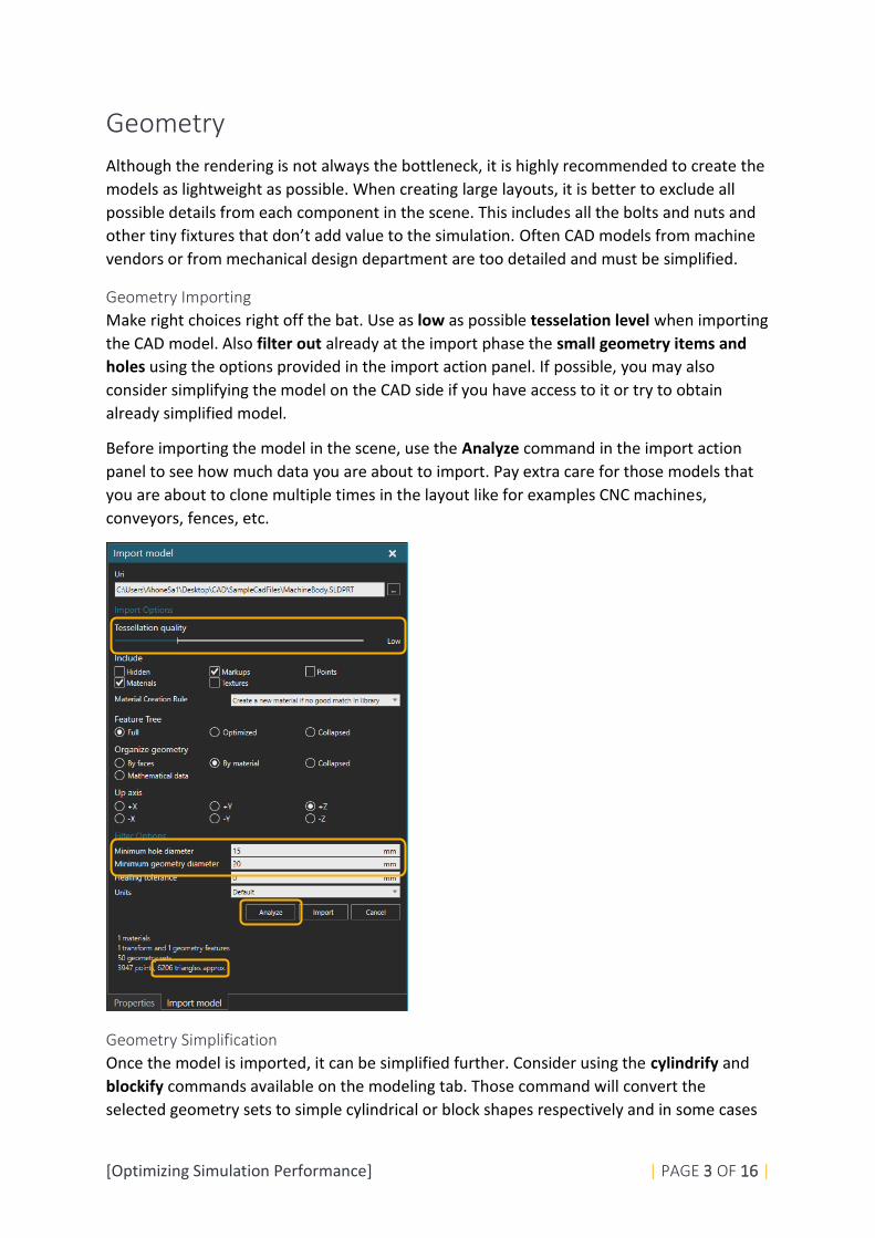
Geometry Importing
Make right choices right off the bat. Use as low as possible tesselation level when importing
the CAD model. Also filter out already at the import phase the small geometry items and
holes using the options provided in the import action panel. If possible, you may also
consider simplifying the model on the CAD side if you have access to it or try to obtain
already simplified model.
Before importing the model in the scene, use the Analyze command in the import action
panel to see how much data you are about to import. Pay extra care for those models that
you are about to clone multiple times in the layout like for examples CNC machines,
conveyors, fences, etc.
Geometry Simplification
Once the model is imported, it can be simplified further. Consider using the cylindrify and
blockify commands available on the modeling tab. Those command will convert the
selected geometry sets to simple cylindrical or block shapes respectively and in some cases

[Optimizing Simulation Performance] | PAGE 4 OF 16 |
saving thousands of triangles without losing too much of the overall shape of the device.
However be careful with these tools as they are destructive commands and can’t be
undone. So, make backup saves before going too crazy with these tools. Also consider using
decimate tool that tries to create the same shape as the selected geometry sets with less
triangles. Same applies to decimate tool as for cylindrify and blockify tool. The undo cannot
be used with these. The original and the result of the blockify command is shown in the
image below. The triangle count for each guide rail decreased from 2276 triangles down to
24 triangles.
Also consider if some shapes can be represented with simple representation by using inbuilt
primitive geometries inside the VC application.
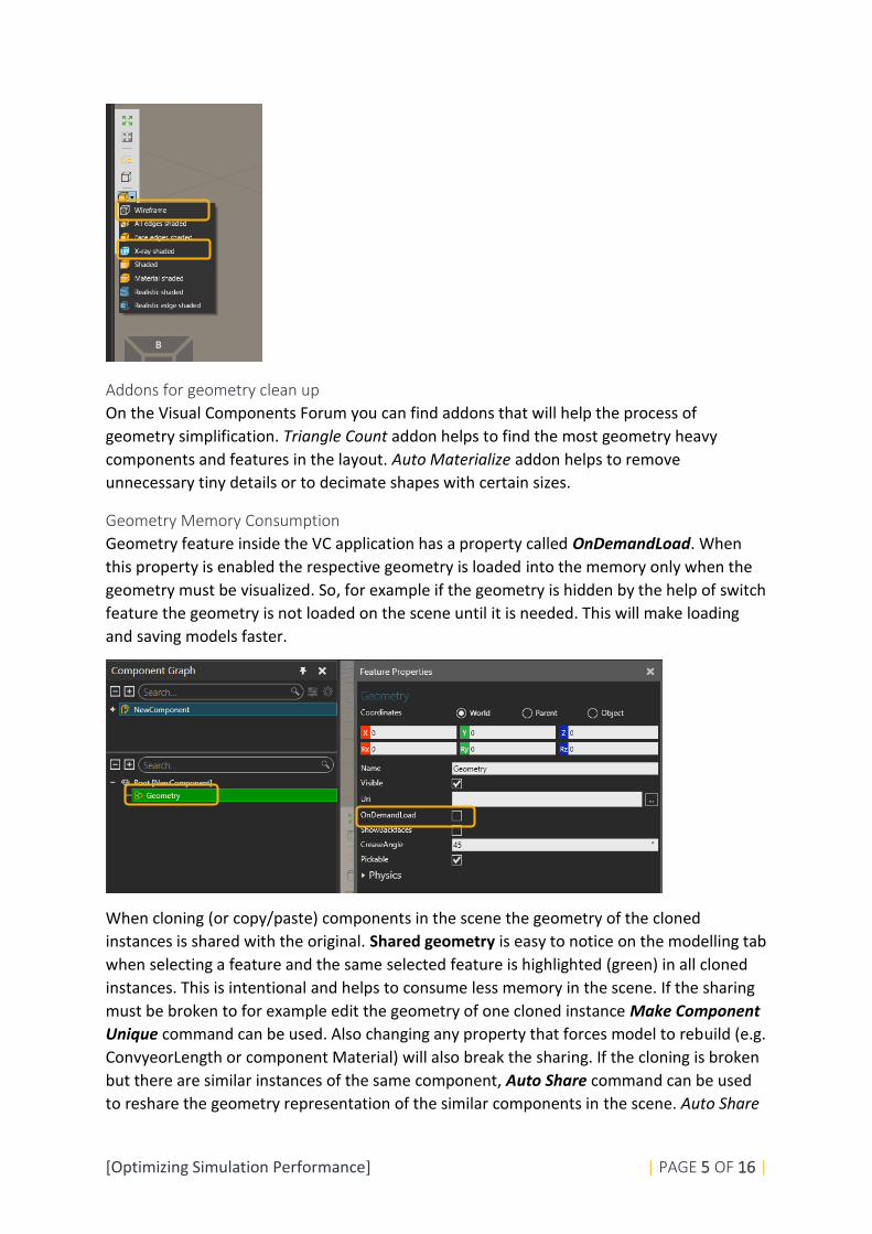
Remove also all the details that no one will ever see. Like the details inside the electric
motors or other details behind the covers that are never revealed during the simulation. The
X-Ray shaded or Wireframe rendering modes are great for checking if there is something
unnecessary hiding inside the imported CAD model.
[Optimizing Simulation Performance] | PAGE 5 OF 16 |
Addons for geometry clean up
On the Visual Components Forum you can find addons that will help the process of
geometry simplification. Triangle Count addon helps to find the most geometry heavy
components and features in the layout. Auto Materialize addon helps to remove
unnecessary tiny details or to decimate shapes with certain sizes.
Geometry Memory Consumption
Geometry feature inside the VC application has a property called OnDemandLoad. When
this property is enabled the respective geometry is loaded into the memory only when the
geometry must be visualized. So, for example if the geometry is hidden by the help of switch
feature the geometry is not loaded on the scene until it is needed. This will make loading
and saving models faster.
When cloning (or copy/paste) components in the scene the geometry of the cloned
instances is shared with the original. Shared geometry is easy to notice on the modelling tab
when selecting a feature and the same selected feature is highlighted (green) in all cloned
instances. This is intentional and helps to consume less memory in the scene. If the sharing
must be broken to for example edit the geometry of one cloned instance Make Component
Unique command can be used. Also changing any property that forces model to rebuild (e.g.
ConvyeorLength or component Material) will also break the sharing. If the cloning is broken
but there are similar instances of the same component, Auto Share command can be used
to reshare the geometry representation of the similar components in the scene. Auto Share

[Optimizing Simulation Performance] | PAGE 6 OF 16 |
is a great tool also to share the geometries of the similar components in the scene that were
not originally cloned. If e.g. two similar conveyors are loaded to the scene from the eCatalog
and they have same property settings in the scene, they will share their geometry
representation if the Auto Share command is used. Shared geometries will also improve the
rendering performance. Auto Share and Make component unique commands can be found
in the 3D context menu under Tools sub menu.
Conclusion regarding geometry
In general heavy geometry will have an effect to the overall performance of the simulation
affecting these (but not limited to these) aspects:
• Rendering preformance
• Performance of the Collision checking, ray casting and volume sensoring
• Performance of the possible geometry rebuilds
• Layout loading and saving times
• Also heavy geometry consumes memory which might be a limiting factor in some
cases
Simulation Behavior
The way the simulation behavior is implemented is maybe the most critical factor affecting
the overall simulation performance. Creating the model in the correct way and simulating
only the necessary details is the way to achieve the best possible simulation performance.
Simplify the simulation behavior
Simulating only the things that add value is a great starting point. Before starting to create
the model think again why this particular model is created. If the purpose is not to create
[Optimizing Simulation Performance] | PAGE 7 OF 16 |
videos with close ups of details, consider excluding all the possible unnecessary details. Do
not add fancy details if they do not serve the purpose. Exclude simulation (animating,
adding motion) of human walk cycles, parts dropping into bins with gravitation, complex
clamp mechanisms and small details inside the machine that no one will ever see.
Try not to create component that can do everything. Having a very versatile component
that can be used in all possible use cases is great, but it is also very hard to model such logic
without sacrificing the simulation performance. Similarly, a Swiss knife is not always the best
tool when carving wood. The components in the public online library provided by Visual
Components are modeled for a generic purpose. They are modeled in a such manner that
they would be suitable for as many as possible use cases. In some cases this versatility
sacrifices the simulation performance a little although in general the models in the online
library can be considered modeled the “correct” way. In some cases consider creating a
simple single purpose component instead of utilizing one of the flexible online library
components.
After all we are creating visual simulations in Visual Components so don’t exclude all the
visual aspects from the simulation so that the simulation will communicate the intended
results in an understandable way. Just start by creating the model by adding the basic
functionality and the overall flow. Then at the end add all the necessary details.
Utilizing the component behavior objects
Use internal behavior functionality as much as possible. In some cases (especially advanced)
VC users may find faster and handier to implement certain functionalities with scripts even
though the same functionality would be achievable by adding and connecting inbuilt
simulation behavior objects. Performance of the inbuilt behaviors is better than an
optimized custom script due to the fact the behavior functionality is executed in the
simulation core. Also, during the simulation run as the Visual Components application needs
to switch between the execution of the simulation core and the python engine (called
context switch) is relatively slow and heavy.
Model rebuilding and updating
When creating new component properties, disable Rebuild and Update Simulation options
if they are not needed. If the rebuild is checked the model geometry tree is re-evaluated
and re-generated when the property value is changed. This is necessary for properties like
conveyor height in order to see the value change effect in the component geometry.
However if there is a property that is used for instance as a counter during simulation,
leaving a rebuild flag on for such property is a serious performance killer as the geometry of
the component is re-evaluated each time the counter value is changed during the
simulation. Design the components so that they won’t need rebuilding during simulation.
Implementing dynamic geometrical changes (like moving links) must be implemented using
the node (i.e. link) tree in the component graph instead of the feature tree. Update
Simulation should be disabled also if the property is not needed in the link tree. However
simulation update for one single component is very fast and does not effect on the
simulation performance nearly as much as rebuilding. For example if a frame feature must
[Optimizing Simulation Performance] | PAGE 8 OF 16 |
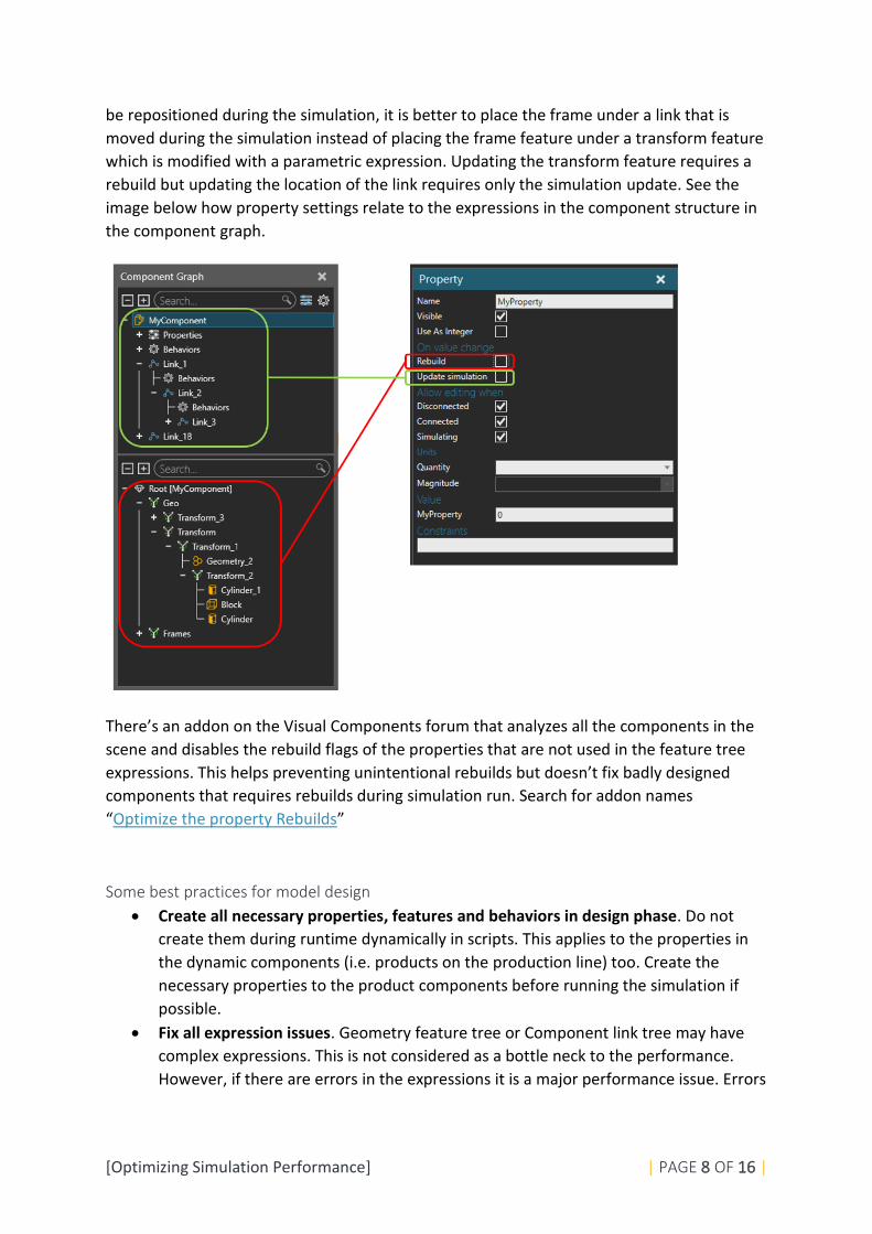
be repositioned during the simulation, it is better to place the frame under a link that is
moved during the simulation instead of placing the frame feature under a transform feature
which is modified with a parametric expression. Updating the transform feature requires a
rebuild but updating the location of the link requires only the simulation update. See the
image below how property settings relate to the expressions in the component structure in
the component graph.
There’s an addon on the Visual Components forum that analyzes all the components in the
scene and disables the rebuild flags of the properties that are not used in the feature tree
expressions. This helps preventing unintentional rebuilds but doesn’t fix badly designed
components that requires rebuilds during simulation run. Search for addon names
“Optimize the property Rebuilds”
Some best practices for model design
• Create all necessary properties, features and behaviors in design phase. Do not
create them during runtime dynamically in scripts. This applies to the properties in
the dynamic components (i.e. products on the production line) too. Create the
necessary properties to the product components before running the simulation if
possible.
• Fix all expression issues. Geometry feature tree or Component link tree may have
complex expressions. This is not considered as a bottle neck to the performance.
However, if there are errors in the expressions it is a major performance issue. Errors

[Optimizing Simulation Performance] | PAGE 9 OF 16 |
are printed to the output panel. Each time the error occurs the expression is re-
evaluated and this causes performance issues.
• Prefer using inbuilt behaviours over custom scripts when possible. Use signals,
sensors, paths, capacity controllers, routing rules etc.
• Use Process modeling feature. Much of the simulation flow and the logic of
machines and devices can be modeled with the Process Modeling capability.
Familiarize yourself with the Process Modeling feature with the lessons and courses
available on the Visual Components Academy and try to implement most of the
simulation utilizing those capabilities and minimize the amount of custom scripting.
• In Robots the python kinematics solver is slower than inbuilt kinematic solvers. If
possible, use the inbuilt solvers and in projects where you can choose a robot model
more freely try to choose one that is not using python kinematics. Also, if possible
try to use more PTP type motions than linear motions with robots with inverse
kinematics as it is less calculation demanding motion type.
• Avoid using raycast and volume sensors if possible. Prefer e.g. Path sensors. If
raycast or volume sensor types are required, pay attention to the frequency those
sensors are utilized by adjusting the sample time property or consider disabling
sampling and connect a signal to the sensor to trigger the sensor only when it’s
needed.
• In conveyor systems, use Accumulate, RetainOffset and SpaceUtilization in the path
behaviors only if they are really needed
Running the simulation
Although the most important factor to the simulation performance is the way the model is
built, there are still certain things that must be considered when running the simulations to
gain maximum performance.
Simulation clock setting
Simulation run settings can be found on the top of the 3D panel. In the settings, set the
Simulation Mode to Virtual Time. It is slightly faster to run the simulation in the virtual time
mode than the real time as the simulation doesn’t need to match the simulation time to real
(Windows) clock.
Rendering mode
When simulating fast, the rendering is not called that often and the scene is rendered only
to keep the 3D window somewhat up to date. But even so using the simpler Shaded

[Optimizing Simulation Performance] | PAGE 10 OF 16 |
rendering mode compared to more demanding rendering modes like Realistic Shaded will
increase the simulation performance. This is more noticeable improvement in the scenes
with large amount of 3D data.
Joint limit checking
Making sure that none of the joints in the devices are exceeding their limit values is often
one reason to simulate. Joint limit checking is however a little bit demanding task for the
simulation engine. If the joint limits are already being checked and verified it is
recommended to disable the limit checking to run simulations faster. Disable joint limit
checking when it is not needed. Disable all joint limit options on the Program tab. This one
setting applies not only to all robots in the scene but to all devices that have servo joints and
motions.
Statistics interval
Gathering statistics is essential when simulating to analyse the simulation afterwards or
during the simulation. However, gathering statistics with very short interval will impact on
the simulation performance. If the simulation run is fairly long, like multiple weeks, the
statistics data may not be needed with the default 60s interval. Consider increasing the
statistics Interval in the Home tab ribbon bar.

[Optimizing Simulation Performance] | PAGE 11 OF 16 |
Simulation Level
Use simulation level feature in multipurpose components. Simulation level option can be
found in the component property panel for each component and under the simulation
configuration settings for the whole layout level (applies to all components). Simulation
behavior for each component must be implemented separately to support Simulation Level
feature. For example, in fast mode some servo motions can be replaced with simple delays
in scripts. The only behavior that automatically utilizes Fast Mode is a physics cable at the
moment. Rest of the support is in python scripts. Some online catalog library models utilize
this feature by controlling the level of simulation details in the component implementation.
For example, the Process Modeling resources in the online catalog utilizes the simulation
level feature. If there are no components in the scene that utilizes the Simulation Level
feature, the option in the settings is disabled.
Add this event method to a component script to register the component to utilize the
Simulation Level
Python scripts
In general, it is better to implement simulation logic with inbuilt behaviors, statements in
the Process Executors and/or in Robot programs. But to achieve the necessary logic python
scripts are often needed. To maximize the simulation performance certain aspect in scripts
must be considered.
Utilize events in scripts
Instead of testing certain condition repeatedly (polling) with a high frequency it is better to
utilize events and model the logic with discrete events. In the example scripts below the top
[Optimizing Simulation Performance] | PAGE 12 OF 16 |
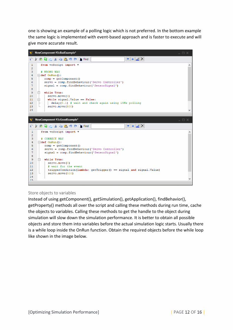
one is showing an example of a polling logic which is not preferred. In the bottom example
the same logic is implemented with event-based approach and is faster to execute and will
give more accurate result.
Store objects to variables
Instead of using getComponent(), getSimulation(), getApplication(), findBehavior(),
getProperty() methods all over the script and calling these methods during run time, cache
the objects to variables. Calling these methods to get the handle to the object during
simulation will slow down the simulation performance. It is better to obtain all possible
objects and store them into variables before the actual simulation logic starts. Usually there
is a while loop inside the OnRun function. Obtain the required objects before the while loop
like shown in the image below.

[Optimizing Simulation Performance] | PAGE 13 OF 16 |
Using Print statement
Due to the limited debugging tools in the python a print statement is typically heavily used
during developing the scripts. It is recommended to remove all the unnecessary print outs
from the finished scripts as the print outs will influence the performance of the simulation.
On top of this a clean output panel is easier to follow than an output panel full of test prints
from different components in the layout.
Rebuilding
As mentioned in the Simulation Behavior section of this lesson, the rebuilding of geometry is
heavy. This must be considered also when developing the scripts. Create the logic and the
structure of the models so that the vcComponent.rebuild() or vcFeature.rebuild() methods
are not needed during the simulation run.
Also, when switching the color (i.e. material) of a component during simulation avoid using
vcComponent.Material property and use vcNode.NodeMaterial instead as the NodeMaterial
changing doesn’t require component rebuild. See the bad and good example below.
In the “bad” example the necessary objects are obtained during the simulation run in the
while loop repeatedly. Also the component material of the part object is changed during
simulation that forces the component object to rebuild.

[Optimizing Simulation Performance] | PAGE 14 OF 16 |
In this “good” example the objects are stored into variables before the while loop and
instead of vcComponent.Material property the vcNode.NodeMaterial property is changed.
This won’t require rebuilding but requires setting of the material inheritance to define
where the node material is applied in the model. Force inherit overwrites all material
settings in the part object. This good example is also more readable and easier to maintain.
Hiding and showing geometries during simulation
If certain parts of the model geometry must be hidden or shown during the simulation it is
better to using again the component link tree instead of the feature tree. Avoid using the
switch feature for showing and hiding items during simulation. Switch feature is great for
parametrization of component that doesn’t need to change during simulation. For example
to model a conveyor that can be configured to represent a roll conveyor or a belt conveyor.
To show and hide geometry during simulation run add links and add parts of the geometry
that must be shown or hidden under those links. Then during simulation use vcNode.Visible
property to show and hide the items. This is very fast compared to switch that requires
geometry rebuild.
Updating the scene
Some modifications in the scripts require updating. For example to relocate a node using
vcNode.PositionMatrix property requires a node update after setting a new matrix value.
Instead of using vcSimulation.update(), use vcNode.update() to update only that node that
requires updating.
Creating dynamic components
Like mentioned in the simulation Behavior section of this lesson, using the inbuilt
functionality of the inbuilt behaviors is faster than replicating the same in script. When
dynamic components must be generated to the simulation it is better to use Component
Creator and Product creator behaviors than calling vcApplication.cloneComponent() method
during the simulation.

[Optimizing Simulation Performance] | PAGE 15 OF 16 |
Also, try to add all properties, features and behaviors to the dynamic components before
generating them into the line. Use vcComponentCreator.TemplateComponent to access the
the component to be created before actually creating it. Or when using vcProductCreator
use Product Editor on the Process tab to edit the products to be created.
Keep dynamic components as simple as possible as there can be thousands of intances of
the same component on the line. Also, avoid adding python scripts and other behaviors to
the dynamic components.
Reuse objects
Reuse objects as much as possible instead of recreating them. For example vcMatrix objects
can be reused instead of re-creating them repeatedly with vcMatrix.new() constructor. Use
vcMatrix.identity() method to reset an existing matrix to default zero location.
Similarly vcMotionTarget and vcAction objects can be recycled in order to improve the
performance.
Avoid context switch
When simulation execution must switch between the simulation core and python execution,
it impacts on the simulation performance negatively. Context switch from the python to
simulation engine happens every time the simulation must update or consume simulation
time. For instance when using delay() method the execution from python script must jump
to simulation core to consume the given simulation time and after that jump back to python
execution. It is better do as much as possible python calculation in one shot than a lot of
context switches. Often context switches are hard to avoid but it is good to understand the
concept when trying to optimize the last bits of the simulation performance.
Other examples of methods forcing context switch are: vcServoController.move(),
triggerCondition(), condition(), delay(). In addition vcSimulation.update() causes context
switch in certain layout/component configurations.
Profiling the layout performance
When the layout is done and the performance should be improved, it may be hard to know
where to start the profiling.

[Optimizing Simulation Performance] | PAGE 16 OF 16 |
Profiler Addon
There is a profiling addon available on the forum that will reveal which components in the
layout are most demanding and helps to understand where the bottle neck in the simulation
performance may be.
The addon is called “Profiler”. The addon will give a result that will show total system time
spent and the top 20 most performance expensive components in the layout along with the
number of calls to component behaviors including python scripts and the amount of system
time spent per component. All data (beyond the top 20 list) is dumped to a file located in a
folder shown in the output message.
Top Related