


Languages
Pages
Legal

Optical fiber
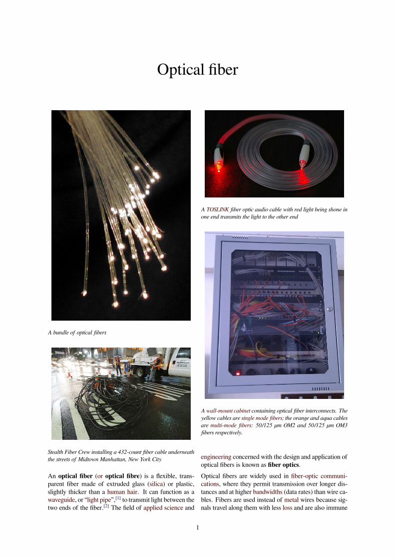
A bundle of optical fibers
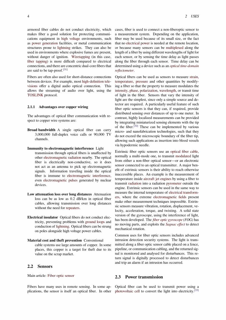
Stealth Fiber Crew installing a 432-count fiber cable underneaththe streets of Midtown Manhattan, New York City
An optical fiber (or optical fibre) is a flexible, trans-parent fiber made of extruded glass (silica) or plastic,slightly thicker than a human hair. It can function as awaveguide, or “light pipe”,[1] to transmit light between thetwo ends of the fiber.[2] The field of applied science and
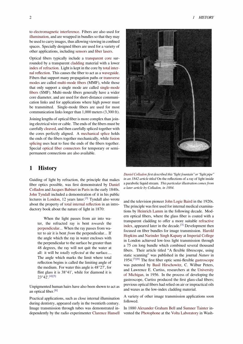
A TOSLINK fiber optic audio cable with red light being shone inone end transmits the light to the other end
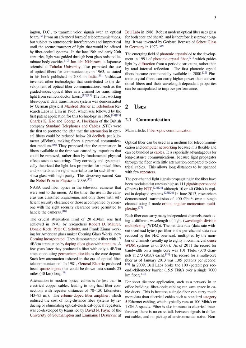
A wall-mount cabinet containing optical fiber interconnects. Theyellow cables are single mode fibers; the orange and aqua cablesare multi-mode fibers: 50/125 µm OM2 and 50/125 µm OM3fibers respectively.
engineering concerned with the design and application ofoptical fibers is known as fiber optics.Optical fibers are widely used in fiber-optic communi-cations, where they permit transmission over longer dis-tances and at higher bandwidths (data rates) than wire ca-bles. Fibers are used instead of metal wires because sig-nals travel along them with less loss and are also immune
1
2 1 HISTORY
to electromagnetic interference. Fibers are also used forillumination, and are wrapped in bundles so that they maybe used to carry images, thus allowing viewing in confinedspaces. Specially designed fibers are used for a variety ofother applications, including sensors and fiber lasers.Optical fibers typically include a transparent core sur-rounded by a transparent cladding material with a lowerindex of refraction. Light is kept in the core by total inter-nal reflection. This causes the fiber to act as a waveguide.Fibers that support many propagation paths or transversemodes are called multi-mode fibers (MMF), while thosethat only support a single mode are called single-modefibers (SMF). Multi-mode fibers generally have a widercore diameter, and are used for short-distance communi-cation links and for applications where high power mustbe transmitted. Single-mode fibers are used for mostcommunication links longer than 1,000 meters (3,300 ft).Joining lengths of optical fiber is more complex than join-ing electrical wire or cable. The ends of the fibers must becarefully cleaved, and then carefully spliced together withthe cores perfectly aligned. A mechanical splice holdsthe ends of the fibers together mechanically, while fusionsplicing uses heat to fuse the ends of the fibers together.Special optical fiber connectors for temporary or semi-permanent connections are also available.
1 History
Guiding of light by refraction, the principle that makesfiber optics possible, was first demonstrated by DanielColladon and Jacques Babinet in Paris in the early 1840s.John Tyndall included a demonstration of it in his publiclectures in London, 12 years later.[3] Tyndall also wroteabout the property of total internal reflection in an intro-ductory book about the nature of light in 1870:
When the light passes from air into wa-ter, the refracted ray is bent towards theperpendicular... When the ray passes from wa-ter to air it is bent from the perpendicular... Ifthe angle which the ray in water encloses withthe perpendicular to the surface be greater than48 degrees, the ray will not quit the water atall: it will be totally reflected at the surface....The angle which marks the limit where totalreflection begins is called the limiting angle ofthe medium. For water this angle is 48°27', forflint glass it is 38°41', while for diamond it is23°42'.[4][5]
Unpigmented human hairs have also been shown to act asan optical fiber.[6]
Practical applications, such as close internal illuminationduring dentistry, appeared early in the twentieth century.Image transmission through tubes was demonstrated in-dependently by the radio experimenter Clarence Hansell
Daniel Colladon first described this “light fountain” or “light pipe”in an 1842 article titled On the reflections of a ray of light insidea parabolic liquid stream. This particular illustration comes froma later article by Colladon, in 1884.
and the television pioneer John Logie Baird in the 1920s.The principle was first used for internal medical examina-tions by Heinrich Lamm in the following decade. Mod-ern optical fibers, where the glass fiber is coated with atransparent cladding to offer a more suitable refractiveindex, appeared later in the decade.[3] Development thenfocused on fiber bundles for image transmission. HaroldHopkins and Narinder Singh Kapany at Imperial Collegein London achieved low-loss light transmission througha 75 cm long bundle which combined several thousandfibers. Their article titled “A flexible fibrescope, usingstatic scanning” was published in the journal Nature in1954.[7][8] The first fiber optic semi-flexible gastroscopewas patented by Basil Hirschowitz, C. Wilbur Peters,and Lawrence E. Curtiss, researchers at the Universityof Michigan, in 1956. In the process of developing thegastroscope, Curtiss produced the first glass-clad fibers;previous optical fibers had relied on air or impractical oilsand waxes as the low-index cladding material.A variety of other image transmission applications soonfollowed.In 1880 Alexander Graham Bell and Sumner Tainter in-vented the Photophone at the Volta Laboratory in Wash-
3
ington, D.C., to transmit voice signals over an opticalbeam.[9] It was an advanced form of telecommunications,but subject to atmospheric interferences and impracticaluntil the secure transport of light that would be offeredby fiber-optical systems. In the late 19th and early 20thcenturies, light was guided through bent glass rods to illu-minate body cavities.[10] Jun-ichi Nishizawa, a Japanesescientist at Tohoku University, also proposed the useof optical fibers for communications in 1963, as statedin his book published in 2004 in India.[11] Nishizawainvented other technologies that contributed to the de-velopment of optical fiber communications, such as thegraded-index optical fiber as a channel for transmittinglight from semiconductor lasers.[12][13] The first workingfiber-optical data transmission system was demonstratedby German physicist Manfred Börner at Telefunken Re-search Labs in Ulm in 1965, which was followed by thefirst patent application for this technology in 1966.[14][15]Charles K. Kao and George A. Hockham of the Britishcompany Standard Telephones and Cables (STC) werethe first to promote the idea that the attenuation in opti-cal fibers could be reduced below 20 decibels per kilo-meter (dB/km), making fibers a practical communica-tion medium.[16] They proposed that the attenuation infibers available at the time was caused by impurities thatcould be removed, rather than by fundamental physicaleffects such as scattering. They correctly and systemati-cally theorized the light-loss properties for optical fiber,and pointed out the right material to use for such fibers—silica glass with high purity. This discovery earned Kaothe Nobel Prize in Physics in 2009.[17]
NASA used fiber optics in the television cameras thatwere sent to the moon. At the time, the use in the cam-eras was classified confidential, and only those with suf-ficient security clearance or those accompanied by some-one with the right security clearance were permitted tohandle the cameras.[18]
The crucial attenuation limit of 20 dB/km was firstachieved in 1970, by researchers Robert D. Maurer,Donald Keck, Peter C. Schultz, and Frank Zimar work-ing for American glass maker Corning Glass Works, nowCorning Incorporated. They demonstrated a fiber with 17dB/km attenuation by doping silica glass with titanium. Afew years later they produced a fiber with only 4 dB/kmattenuation using germanium dioxide as the core dopant.Such low attenuation ushered in the era of optical fibertelecommunication. In 1981, General Electric producedfused quartz ingots that could be drawn into strands 25miles (40 km) long.[19]
Attenuation in modern optical cables is far less than inelectrical copper cables, leading to long-haul fiber con-nections with repeater distances of 70–150 kilometers(43–93 mi). The erbium-doped fiber amplifier, whichreduced the cost of long-distance fiber systems by re-ducing or eliminating optical-electrical-optical repeaters,was co-developed by teams led by David N. Payne of theUniversity of Southampton and Emmanuel Desurvire at
Bell Labs in 1986. Robust modern optical fiber uses glassfor both core and sheath, and is therefore less prone to ag-ing. It was invented by Gerhard Bernsee of Schott Glassin Germany in 1973.[20]
The emerging field of photonic crystals led to the develop-ment in 1991 of photonic-crystal fiber,[21] which guideslight by diffraction from a periodic structure, rather thanby total internal reflection. The first photonic crystalfibers became commercially available in 2000.[22] Pho-tonic crystal fibers can carry higher power than conven-tional fibers and their wavelength-dependent propertiescan be manipulated to improve performance.
2 Uses
2.1 Communication
Main article: Fiber-optic communication
Optical fiber can be used as a medium for telecommuni-cation and computer networking because it is flexible andcan be bundled as cables. It is especially advantageous forlong-distance communications, because light propagatesthrough the fiber with little attenuation compared to elec-trical cables. This allows long distances to be spannedwith few repeaters.The per-channel light signals propagating in the fiber havebeenmodulated at rates as high as 111 gigabits per second(Gbit/s) by NTT,[23][24] although 10 or 40 Gbit/s is typi-cal in deployed systems.[25][26] In June 2013, researchersdemonstrated transmission of 400 Gbit/s over a singlechannel using 4-mode orbital angular momentum multi-plexing.[27]
Each fiber can carry many independent channels, each us-ing a different wavelength of light (wavelength-divisionmultiplexing (WDM)). The net data rate (data rate with-out overhead bytes) per fiber is the per-channel data ratereduced by the FEC overhead, multiplied by the num-ber of channels (usually up to eighty in commercial denseWDM systems as of 2008). As of 2011 the record forbandwidth on a single core was 101 Tbit/s (370 chan-nels at 273 Gbit/s each).[28] The record for a multi-corefiber as of January 2013 was 1.05 petabits per second.[29] In 2009, Bell Labs broke the 100 (petabit per sec-ond)×kilometer barrier (15.5 Tbit/s over a single 7000km fiber).[30]
For short distance application, such as a network in anoffice building, fiber-optic cabling can save space in ca-ble ducts. This is because a single fiber can carry muchmore data than electrical cables such as standard category5 Ethernet cabling, which typically runs at 100 Mbit/s or1 Gbit/s speeds. Fiber is also immune to electrical inter-ference; there is no cross-talk between signals in differ-ent cables, and no pickup of environmental noise. Non-
4 2 USES
armored fiber cables do not conduct electricity, whichmakes fiber a good solution for protecting communi-cations equipment in high voltage environments, suchas power generation facilities, or metal communicationstructures prone to lightning strikes. They can also beused in environments where explosive fumes are present,without danger of ignition. Wiretapping (in this case,fiber tapping) is more difficult compared to electricalconnections, and there are concentric dual-core fibers thatare said to be tap-proof.[31]
Fibers are often also used for short-distance connectionsbetween devices. For example, most high-definition tele-visions offer a digital audio optical connection. Thisallows the streaming of audio over light, using theTOSLINK protocol.
2.1.1 Advantages over copper wiring
The advantages of optical fiber communication with re-spect to copper wire systems are:
Broad bandwidth A single optical fiber can carry3,000,000 full-duplex voice calls or 90,000 TVchannels.
Immunity to electromagnetic interference Lighttransmission through optical fibers is unaffected byother electromagnetic radiation nearby. The opticalfiber is electrically non-conductive, so it doesnot act as an antenna to pick up electromagneticsignals. Information traveling inside the opticalfiber is immune to electromagnetic interference,even electromagnetic pulses generated by nucleardevices.
Low attenuation loss over long distances Attenuationloss can be as low as 0.2 dB/km in optical fibercables, allowing transmission over long distanceswithout the need for repeaters.
Electrical insulator Optical fibers do not conduct elec-tricity, preventing problems with ground loops andconduction of lightning. Optical fibers can be strungon poles alongside high voltage power cables.
Material cost and theft prevention Conventionalcable systems use large amounts of copper. In someplaces, this copper is a target for theft due to itsvalue on the scrap market.
2.2 Sensors
Main article: Fiber optic sensor
Fibers have many uses in remote sensing. In some ap-plications, the sensor is itself an optical fiber. In other
cases, fiber is used to connect a non-fiberoptic sensor toa measurement system. Depending on the application,fiber may be used because of its small size, or the factthat no electrical power is needed at the remote location,or because many sensors can be multiplexed along thelength of a fiber by using different wavelengths of light foreach sensor, or by sensing the time delay as light passesalong the fiber through each sensor. Time delay can bedetermined using a device such as an optical time-domainreflectometer.Optical fibers can be used as sensors to measure strain,temperature, pressure and other quantities by modify-ing a fiber so that the property to measure modulates theintensity, phase, polarization, wavelength, or transit timeof light in the fiber. Sensors that vary the intensity oflight are the simplest, since only a simple source and de-tector are required. A particularly useful feature of suchfiber optic sensors is that they can, if required, providedistributed sensing over distances of up to one meter. Incontrast, highly localized measurements can be providedby integrating miniaturized sensing elements with the tipof the fiber.[32] These can be implemented by variousmicro- and nanofabrication technologies, such that theydo not exceed the microscopic boundary of the fiber tip,allowing such applications as insertion into blood vesselsvia hypodermic needle.Extrinsic fiber optic sensors use an optical fiber cable,normally a multi-mode one, to transmit modulated lightfrom either a non-fiber optical sensor—or an electronicsensor connected to an optical transmitter. A major ben-efit of extrinsic sensors is their ability to reach otherwiseinaccessible places. An example is the measurement oftemperature inside aircraft jet engines by using a fiber totransmit radiation into a radiation pyrometer outside theengine. Extrinsic sensors can be used in the same way tomeasure the internal temperature of electrical transform-ers, where the extreme electromagnetic fields presentmake other measurement techniques impossible. Extrin-sic sensors measure vibration, rotation, displacement, ve-locity, acceleration, torque, and twisting. A solid stateversion of the gyroscope, using the interference of light,has been developed. The fiber optic gyroscope (FOG) hasno moving parts, and exploits the Sagnac effect to detectmechanical rotation.Common uses for fiber optic sensors includes advancedintrusion detection security systems. The light is trans-mitted along a fiber optic sensor cable placed on a fence,pipeline, or communication cabling, and the returned sig-nal is monitored and analysed for disturbances. This re-turn signal is digitally processed to detect disturbancesand trip an alarm if an intrusion has occurred.
2.3 Power transmission
Optical fiber can be used to transmit power using aphotovoltaic cell to convert the light into electricity.[33]
2.4 Other uses 5
While this method of power transmission is not as effi-cient as conventional ones, it is especially useful in situa-tions where it is desirable not to have a metallic conductoras in the case of use near MRI machines, which producestrong magnetic fields.[34] Other examples are for pow-ering electronics in high-powered antenna elements andmeasurement devices used in high-voltage transmissionequipment.
2.4 Other uses
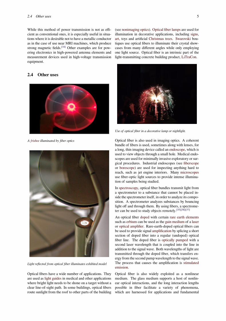
A frisbee illuminated by fiber optics
Light reflected from optical fiber illuminates exhibited model
Optical fibers have a wide number of applications. Theyare used as light guides in medical and other applicationswhere bright light needs to be shone on a target without aclear line-of-sight path. In some buildings, optical fibersroute sunlight from the roof to other parts of the building
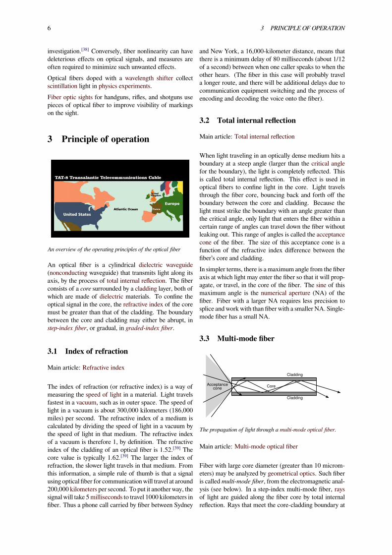
(see nonimaging optics). Optical fiber lamps are used forillumination in decorative applications, including signs,art, toys and artificial Christmas trees. Swarovski bou-tiques use optical fibers to illuminate their crystal show-cases from many different angles while only employingone light source. Optical fiber is an intrinsic part of thelight-transmitting concrete building product, LiTraCon.
Use of optical fiber in a decorative lamp or nightlight.
Optical fiber is also used in imaging optics. A coherentbundle of fibers is used, sometimes along with lenses, fora long, thin imaging device called an endoscope, which isused to view objects through a small hole. Medical endo-scopes are used for minimally invasive exploratory or sur-gical procedures. Industrial endoscopes (see fiberscopeor borescope) are used for inspecting anything hard toreach, such as jet engine interiors. Many microscopesuse fiber-optic light sources to provide intense illumina-tion of samples being studied.In spectroscopy, optical fiber bundles transmit light froma spectrometer to a substance that cannot be placed in-side the spectrometer itself, in order to analyze its compo-sition. A spectrometer analyzes substances by bouncinglight off and through them. By using fibers, a spectrome-ter can be used to study objects remotely.[35][36][37]
An optical fiber doped with certain rare earth elementssuch as erbium can be used as the gain medium of a laseror optical amplifier. Rare-earth-doped optical fibers canbe used to provide signal amplification by splicing a shortsection of doped fiber into a regular (undoped) opticalfiber line. The doped fiber is optically pumped with asecond laser wavelength that is coupled into the line inaddition to the signal wave. Both wavelengths of light aretransmitted through the doped fiber, which transfers en-ergy from the second pumpwavelength to the signal wave.The process that causes the amplification is stimulatedemission.Optical fiber is also widely exploited as a nonlinearmedium. The glass medium supports a host of nonlin-ear optical interactions, and the long interaction lengthspossible in fiber facilitate a variety of phenomena,which are harnessed for applications and fundamental
6 3 PRINCIPLE OF OPERATION
investigation.[38] Conversely, fiber nonlinearity can havedeleterious effects on optical signals, and measures areoften required to minimize such unwanted effects.Optical fibers doped with a wavelength shifter collectscintillation light in physics experiments.Fiber optic sights for handguns, rifles, and shotguns usepieces of optical fiber to improve visibility of markingson the sight.
3 Principle of operation
An overview of the operating principles of the optical fiber
An optical fiber is a cylindrical dielectric waveguide(nonconducting waveguide) that transmits light along itsaxis, by the process of total internal reflection. The fiberconsists of a core surrounded by a cladding layer, both ofwhich are made of dielectric materials. To confine theoptical signal in the core, the refractive index of the coremust be greater than that of the cladding. The boundarybetween the core and cladding may either be abrupt, instep-index fiber, or gradual, in graded-index fiber.
3.1 Index of refraction
Main article: Refractive index
The index of refraction (or refractive index) is a way ofmeasuring the speed of light in a material. Light travelsfastest in a vacuum, such as in outer space. The speed oflight in a vacuum is about 300,000 kilometers (186,000miles) per second. The refractive index of a medium iscalculated by dividing the speed of light in a vacuum bythe speed of light in that medium. The refractive indexof a vacuum is therefore 1, by definition. The refractiveindex of the cladding of an optical fiber is 1.52.[39] Thecore value is typically 1.62.[39] The larger the index ofrefraction, the slower light travels in that medium. Fromthis information, a simple rule of thumb is that a signalusing optical fiber for communication will travel at around200,000 kilometers per second. To put it another way, thesignal will take 5milliseconds to travel 1000 kilometers infiber. Thus a phone call carried by fiber between Sydney
and New York, a 16,000-kilometer distance, means thatthere is a minimum delay of 80 milliseconds (about 1/12of a second) between when one caller speaks to when theother hears. (The fiber in this case will probably travela longer route, and there will be additional delays due tocommunication equipment switching and the process ofencoding and decoding the voice onto the fiber).
3.2 Total internal reflection
Main article: Total internal reflection
When light traveling in an optically dense medium hits aboundary at a steep angle (larger than the critical anglefor the boundary), the light is completely reflected. Thisis called total internal reflection. This effect is used inoptical fibers to confine light in the core. Light travelsthrough the fiber core, bouncing back and forth off theboundary between the core and cladding. Because thelight must strike the boundary with an angle greater thanthe critical angle, only light that enters the fiber within acertain range of angles can travel down the fiber withoutleaking out. This range of angles is called the acceptancecone of the fiber. The size of this acceptance cone is afunction of the refractive index difference between thefiber’s core and cladding.In simpler terms, there is a maximum angle from the fiberaxis at which light may enter the fiber so that it will prop-agate, or travel, in the core of the fiber. The sine of thismaximum angle is the numerical aperture (NA) of thefiber. Fiber with a larger NA requires less precision tosplice and work with than fiber with a smaller NA. Single-mode fiber has a small NA.
3.3 Multi-mode fiber
Acceptancecone
Cladding
Cladding
Core
The propagation of light through a multi-mode optical fiber.
Main article: Multi-mode optical fiber
Fiber with large core diameter (greater than 10 microm-eters) may be analyzed by geometrical optics. Such fiberis calledmulti-mode fiber, from the electromagnetic anal-ysis (see below). In a step-index multi-mode fiber, raysof light are guided along the fiber core by total internalreflection. Rays that meet the core-cladding boundary at
3.4 Single-mode fiber 7
A laser bouncing down an acrylic rod, illustrating the total inter-nal reflection of light in a multi-mode optical fiber.
a high angle (measured relative to a line normal to theboundary), greater than the critical angle for this bound-ary, are completely reflected. The critical angle (mini-mum angle for total internal reflection) is determined bythe difference in index of refraction between the core andcladding materials. Rays that meet the boundary at a lowangle are refracted from the core into the cladding, anddo not convey light and hence information along the fiber.The critical angle determines the acceptance angle of thefiber, often reported as a numerical aperture. A high nu-merical aperture allows light to propagate down the fiberin rays both close to the axis and at various angles, al-lowing efficient coupling of light into the fiber. How-ever, this high numerical aperture increases the amount ofdispersion as rays at different angles have different pathlengths and therefore take different times to traverse thefiber.
380µm 200µm
125µm
50-100µm
125µm
-10µm
Output pulse
Step index fiber
Graded index fiber
Singlemode fiber
Input pulseIndex of refraction
n
n
n
Optical fiber types.
In graded-index fiber, the index of refraction in the coredecreases continuously between the axis and the cladding.This causes light rays to bend smoothly as they approachthe cladding, rather than reflecting abruptly from thecore-cladding boundary. The resulting curved paths re-duce multi-path dispersion because high angle rays passmore through the lower-index periphery of the core,rather than the high-index center. The index profile ischosen to minimize the difference in axial propagationspeeds of the various rays in the fiber. This ideal index
profile is very close to a parabolic relationship betweenthe index and the distance from the axis.
3.4 Single-mode fiber
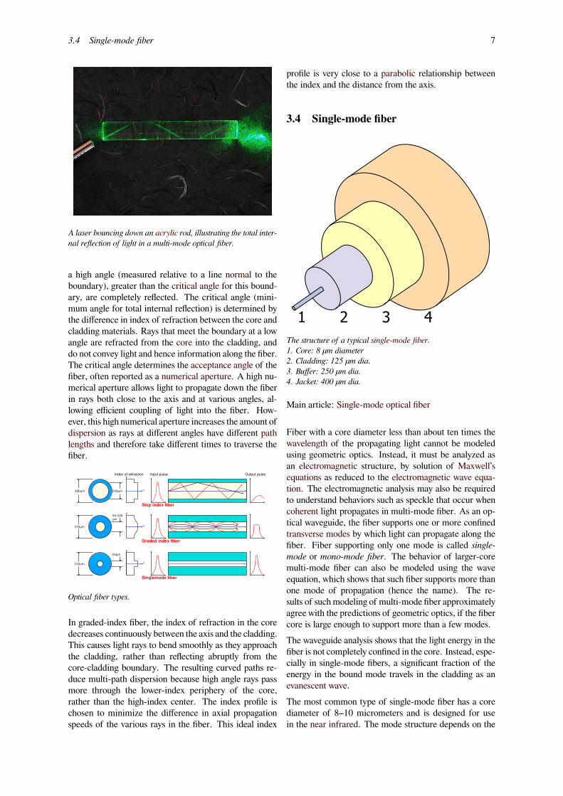
The structure of a typical single-mode fiber.1. Core: 8 µm diameter2. Cladding: 125 µm dia.3. Buffer: 250 µm dia.4. Jacket: 400 µm dia.
Main article: Single-mode optical fiber
Fiber with a core diameter less than about ten times thewavelength of the propagating light cannot be modeledusing geometric optics. Instead, it must be analyzed asan electromagnetic structure, by solution of Maxwell’sequations as reduced to the electromagnetic wave equa-tion. The electromagnetic analysis may also be requiredto understand behaviors such as speckle that occur whencoherent light propagates in multi-mode fiber. As an op-tical waveguide, the fiber supports one or more confinedtransverse modes by which light can propagate along thefiber. Fiber supporting only one mode is called single-mode or mono-mode fiber. The behavior of larger-coremulti-mode fiber can also be modeled using the waveequation, which shows that such fiber supports more thanone mode of propagation (hence the name). The re-sults of such modeling of multi-mode fiber approximatelyagree with the predictions of geometric optics, if the fibercore is large enough to support more than a few modes.The waveguide analysis shows that the light energy in thefiber is not completely confined in the core. Instead, espe-cially in single-mode fibers, a significant fraction of theenergy in the bound mode travels in the cladding as anevanescent wave.The most common type of single-mode fiber has a corediameter of 8–10 micrometers and is designed for usein the near infrared. The mode structure depends on the
8 4 MECHANISMS OF ATTENUATION
wavelength of the light used, so that this fiber actuallysupports a small number of additional modes at visiblewavelengths. Multi-mode fiber, by comparison, is manu-factured with core diameters as small as 50 micrometersand as large as hundreds of micrometers. The normalizedfrequency V for this fiber should be less than the first zeroof the Bessel function J0 (approximately 2.405).
3.5 Special-purpose fiber
Some special-purpose optical fiber is constructed with anon-cylindrical core and/or cladding layer, usually withan elliptical or rectangular cross-section. These includepolarization-maintaining fiber and fiber designed to sup-press whispering gallery mode propagation. Polarization-maintaining fiber is a unique type of fiber that is com-monly used in fiber optic sensors due to its ability tomain-tain the polarization of the light inserted into it.Photonic-crystal fiber is made with a regular pattern ofindex variation (often in the form of cylindrical holesthat run along the length of the fiber). Such fiber usesdiffraction effects instead of or in addition to total in-ternal reflection, to confine light to the fiber’s core. Theproperties of the fiber can be tailored to a wide variety ofapplications.
4 Mechanisms of attenuation
Light attenuation by ZBLAN and silica fibers
Main article: Transparent materials
Attenuation in fiber optics, also known as transmissionloss, is the reduction in intensity of the light beam (orsignal) as it travels through the transmission medium. At-tenuation coefficients in fiber optics usually use units ofdB/km through the medium due to the relatively highquality of transparency of modern optical transmissionmedia. The medium is usually a fiber of silica glass thatconfines the incident light beam to the inside. Attenu-ation is an important factor limiting the transmission ofa digital signal across large distances. Thus, much re-search has gone into both limiting the attenuation and
maximizing the amplification of the optical signal. Em-pirical research has shown that attenuation in optical fiberis caused primarily by both scattering and absorption.Single-mode optical fibers can be made with extremelylow loss. Corning’s SMF-28 fiber, a standard single-modefiber for telecommunications wavelengths, has a loss of0.17 dB/km at 1550 nm.[40] For example, an 8 km lengthof SMF-28 transmits nearly 75% of light at 1550 nm. Ithas been noted that if ocean water was as clear as fiber,one could see all the way to the bottom even of the Mar-ianas Trench in the Pacific Ocean, a depth of 36,000feet.[41]
4.1 Light scattering
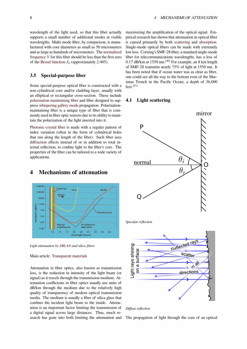
P
Q
normal O
mirror
Specular reflection
Diffuse reflection
The propagation of light through the core of an optical
9
fiber is based on total internal reflection of the lightwave.Rough and irregular surfaces, even at the molecular level,can cause light rays to be reflected in random directions.This is called diffuse reflection or scattering, and it is typ-ically characterized by wide variety of reflection angles.Light scattering depends on the wavelength of the lightbeing scattered. Thus, limits to spatial scales of visibilityarise, depending on the frequency of the incident light-wave and the physical dimension (or spatial scale) of thescattering center, which is typically in the form of somespecific micro-structural feature. Since visible light has awavelength of the order of one micrometer (one millionthof a meter) scattering centers will have dimensions on asimilar spatial scale.Thus, attenuation results from the incoherent scatter-ing of light at internal surfaces and interfaces. In(poly)crystalline materials such as metals and ceramics,in addition to pores, most of the internal surfaces or in-terfaces are in the form of grain boundaries that sepa-rate tiny regions of crystalline order. It has recently beenshown that when the size of the scattering center (or grainboundary) is reduced below the size of the wavelength ofthe light being scattered, the scattering no longer occursto any significant extent. This phenomenon has given riseto the production of transparent ceramic materials.Similarly, the scattering of light in optical quality glassfiber is caused by molecular level irregularities (com-positional fluctuations) in the glass structure. Indeed,one emerging school of thought is that a glass is sim-ply the limiting case of a polycrystalline solid. Withinthis framework, “domains” exhibiting various degrees ofshort-range order become the building blocks of bothmetals and alloys, as well as glasses and ceramics. Dis-tributed both between and within these domains aremicro-structural defects that provide the most ideal loca-tions for light scattering. This same phenomenon is seenas one of the limiting factors in the transparency of IRmissile domes.[42]
At high optical powers, scattering can also be caused bynonlinear optical processes in the fiber.[43][44]
4.2 UV-Vis-IR absorption
In addition to light scattering, attenuation or signal losscan also occur due to selective absorption of specificwavelengths, in a manner similar to that responsible forthe appearance of color. Primary material considerationsinclude both electrons and molecules as follows:1) At the electronic level, it depends on whether the elec-tron orbitals are spaced (or “quantized”) such that theycan absorb a quantum of light (or photon) of a specificwavelength or frequency in the ultraviolet (UV) or visi-ble ranges. This is what gives rise to color.2) At the atomic or molecular level, it depends on the fre-quencies of atomic or molecular vibrations or chemical
bonds, how close-packed its atoms or molecules are, andwhether or not the atoms or molecules exhibit long-rangeorder. These factors will determine the capacity of thematerial transmitting longer wavelengths in the infrared(IR), far IR, radio and microwave ranges.The design of any optically transparent device requiresthe selection of materials based upon knowledge of itsproperties and limitations. The Lattice absorption char-acteristics observed at the lower frequency regions (midIR to far-infrared wavelength range) define the long-wavelength transparency limit of the material. They arethe result of the interactive coupling between the motionsof thermally induced vibrations of the constituent atomsand molecules of the solid lattice and the incident lightwave radiation. Hence, all materials are bounded by lim-iting regions of absorption caused by atomic and molec-ular vibrations (bond-stretching)in the far-infrared (>10µm).Thus, multi-phonon absorption occurs when two ormore phonons simultaneously interact to produce electricdipole moments with which the incident radiation maycouple. These dipoles can absorb energy from the inci-dent radiation, reaching a maximum coupling with theradiation when the frequency is equal to the fundamen-tal vibrational mode of the molecular dipole (e.g. Si-Obond) in the far-infrared, or one of its harmonics.The selective absorption of infrared (IR) light by a partic-ular material occurs because the selected frequency of thelight wave matches the frequency (or an integer multipleof the frequency) at which the particles of that materialvibrate. Since different atoms and molecules have differ-ent natural frequencies of vibration, they will selectivelyabsorb different frequencies (or portions of the spectrum)of infrared (IR) light.Reflection and transmission of light waves occur becausethe frequencies of the light waves do not match the naturalresonant frequencies of vibration of the objects. When IRlight of these frequencies strikes an object, the energy iseither reflected or transmitted.
5 Manufacturing
5.1 Materials
Glass optical fibers are almost always made fromsilica, but some other materials, such as fluorozirconate,fluoroaluminate, and chalcogenide glasses as well ascrystalline materials like sapphire, are used for longer-wavelength infrared or other specialized applications. Sil-ica and fluoride glasses usually have refractive indices ofabout 1.5, but some materials such as the chalcogenidescan have indices as high as 3. Typically the index differ-ence between core and cladding is less than one percent.
10 5 MANUFACTURING
Plastic optical fibers (POF) are commonly step-indexmulti-mode fibers with a core diameter of 0.5 millime-ters or larger. POF typically have higher attenuation co-efficients than glass fibers, 1 dB/m or higher, and this highattenuation limits the range of POF-based systems.
5.1.1 Silica
Silica exhibits fairly good optical transmission over a widerange of wavelengths. In the near-infrared (near IR) por-tion of the spectrum, particularly around 1.5 μm, silicacan have extremely low absorption and scattering lossesof the order of 0.2 dB/km. Such remarkably low lossesare possible only because ultra-pure silicon is available,it being essential for manufacturing integrated circuitsand discrete transistors. A high transparency in the 1.4-μm region is achieved by maintaining a low concentra-tion of hydroxyl groups (OH). Alternatively, a high OHconcentration is better for transmission in the ultraviolet(UV) region.[45]
Silica can be drawn into fibers at reasonably high temper-atures, and has a fairly broad glass transformation range.One other advantage is that fusion splicing and cleavingof silica fibers is relatively effective. Silica fiber also hashigh mechanical strength against both pulling and evenbending, provided that the fiber is not too thick and thatthe surfaces have been well prepared during processing.Even simple cleaving (breaking) of the ends of the fibercan provide nicely flat surfaces with acceptable opticalquality. Silica is also relatively chemically inert. In par-ticular, it is not hygroscopic (does not absorb water).Silica glass can be doped with various materials. Onepurpose of doping is to raise the refractive index (e.g.with germanium dioxide (GeO2) or aluminium oxide(Al2O3)) or to lower it (e.g. with fluorine or boron tri-oxide (B2O3)). Doping is also possible with laser-activeions (for example, rare earth-doped fibers) in order to ob-tain active fibers to be used, for example, in fiber am-plifiers or laser applications. Both the fiber core andcladding are typically doped, so that the entire assem-bly (core and cladding) is effectively the same compound(e.g. an aluminosilicate, germanosilicate, phosphosilicateor borosilicate glass).Particularly for active fibers, pure silica is usually not avery suitable host glass, because it exhibits a low solubilityfor rare earth ions. This can lead to quenching effects dueto clustering of dopant ions. Aluminosilicates are muchmore effective in this respect.Silica fiber also exhibits a high threshold for optical dam-age. This property ensures a low tendency for laser-induced breakdown. This is important for fiber amplifierswhen utilized for the amplification of short pulses.Because of these properties silica fibers are the ma-terial of choice in many optical applications, such ascommunications (except for very short distances with
plastic optical fiber), fiber lasers, fiber amplifiers, andfiber-optic sensors. Large efforts put forth in the de-velopment of various types of silica fibers have fur-ther increased the performance of such fibers over othermaterials.[46][47][48][49][50][51][52][53]
5.1.2 Fluoride glass
Fluoride glass is a class of non-oxide optical qualityglasses composed of fluorides of various metals. Becauseof their low viscosity, it is very difficult to completelyavoid crystallization while processing it through the glasstransition (or drawing the fiber from the melt). Thus, al-though heavy metal fluoride glasses (HMFG) exhibit verylow optical attenuation, they are not only difficult to man-ufacture, but are quite fragile, and have poor resistance tomoisture and other environmental attacks. Their best at-tribute is that they lack the absorption band associatedwith the hydroxyl (OH) group (3200–3600 cm−1; i.e.,2777–3125 nm or 2.78–3.13 μm), which is present innearly all oxide-based glasses.An example of a heavy metal fluoride glass is the ZBLANglass group, composed of zirconium, barium, lanthanum,aluminium, and sodium fluorides. Their main technolog-ical application is as optical waveguides in both planarand fiber form. They are advantageous especially in themid-infrared (2000–5000 nm) range.HMFGs were initially slated for optical fiber applications,because the intrinsic losses of a mid-IR fiber could inprinciple be lower than those of silica fibers, which aretransparent only up to about 2 μm. However, such lowlosses were never realized in practice, and the fragilityand high cost of fluoride fibers made them less thanideal as primary candidates. Later, the utility of fluo-ride fibers for various other applications was discovered.These include mid-IR spectroscopy, fiber optic sensors,thermometry, and imaging. Also, fluoride fibers can beused for guided lightwave transmission in media such asYAG (yttrium aluminium garnet) lasers at 2.9 μm, as re-quired for medical applications (e.g. ophthalmology anddentistry).[54][55]
5.1.3 Phosphate glass
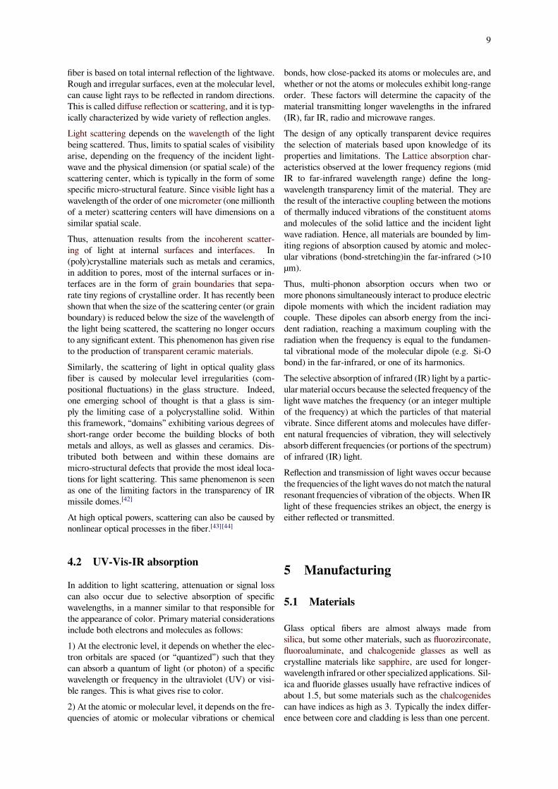
Phosphate glass constitutes a class of optical glasses com-posed of metaphosphates of various metals. Instead ofthe SiO4 tetrahedra observed in silicate glasses, the build-ing block for this glass former is phosphorus pentox-ide (P2O5), which crystallizes in at least four differentforms. The most familiar polymorph (see figure) com-prises molecules of P4O10.Phosphate glasses can be advantageous over silica glassesfor optical fibers with a high concentration of doping rareearth ions. A mix of fluoride glass and phosphate glass isfluorophosphate glass.[56][57]
5.2 Process 11
The P4O10 cagelike structure—the basic building block for phos-phate glass.
5.1.4 Chalcogenide glass
The chalcogens—the elements in group 16 of theperiodic table—particularly sulfur (S), selenium (Se) andtellurium (Te)—react withmore electropositive elements,such as silver, to form chalcogenides. These are ex-tremely versatile compounds, in that they can be crys-talline or amorphous, metallic or semiconducting, andconductors of ions or electrons. Glass containing chalco-genides can be used to make fibers for far infrared trans-mission.
5.2 Process
5.2.1 Preform
Standard optical fibers are made by first constructing alarge-diameter “preform” with a carefully controlled re-fractive index profile, and then “pulling” the preform toform the long, thin optical fiber. The preform is com-monly made by three chemical vapor deposition methods:inside vapor deposition, outside vapor deposition, and va-por axial deposition.[58]
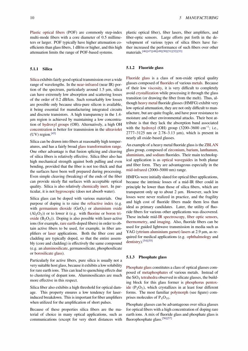
With inside vapor deposition, the preform starts as a hol-low glass tube approximately 40 centimeters (16 in) long,which is placed horizontally and rotated slowly on a lathe.Gases such as silicon tetrachloride (SiCl4) or germaniumtetrachloride (GeCl4) are injected with oxygen in the endof the tube. The gases are then heated by means of an ex-ternal hydrogen burner, bringing the temperature of thegas up to 1900 K (1600 °C, 3000 °F), where the tetra-chlorides react with oxygen to produce silica or germania(germanium dioxide) particles. When the reaction condi-tions are chosen to allow this reaction to occur in the gasphase throughout the tube volume, in contrast to earlier
MM
M
M
M
Gas mixturee.g. SiCl4, GeCl4O2, He
Tube rotation
O2H2
SF6
Depositingparticles
Mixing valves
O2 POCl
GeCl
SiCl4
4
3
Heor
Soot
Traversing high
Reaction Zone
temperature torch
Illustration of the modified chemical vapor deposition (inside)process
techniques where the reaction occurred only on the glasssurface, this technique is called modified chemical vapordeposition (MCVD).The oxide particles then agglomerate to form large parti-cle chains, which subsequently deposit on the walls of thetube as soot. The deposition is due to the large differencein temperature between the gas core and the wall causingthe gas to push the particles outwards (this is known asthermophoresis). The torch is then traversed up and downthe length of the tube to deposit thematerial evenly. Afterthe torch has reached the end of the tube, it is then broughtback to the beginning of the tube and the deposited par-ticles are then melted to form a solid layer. This processis repeated until a sufficient amount of material has beendeposited. For each layer the composition can be modi-fied by varying the gas composition, resulting in precisecontrol of the finished fiber’s optical properties.In outside vapor deposition or vapor axial deposition, theglass is formed by flame hydrolysis, a reaction in whichsilicon tetrachloride and germanium tetrachloride are ox-idized by reaction with water (H2O) in an oxyhydrogenflame. In outside vapor deposition the glass is depositedonto a solid rod, which is removed before further process-ing. In vapor axial deposition, a short seed rod is used,and a porous preform, whose length is not limited by thesize of the source rod, is built up on its end. The porouspreform is consolidated into a transparent, solid preformby heating to about 1800 K (1500 °C, 2800 °F).Typical communications fiber uses a circular preform.For some applications such as double-clad fibers anotherform is preferred.[59] In fiber lasers based on double-cladfiber, an asymmetric shape improves the filling factor for
12 6 PRACTICAL ISSUES
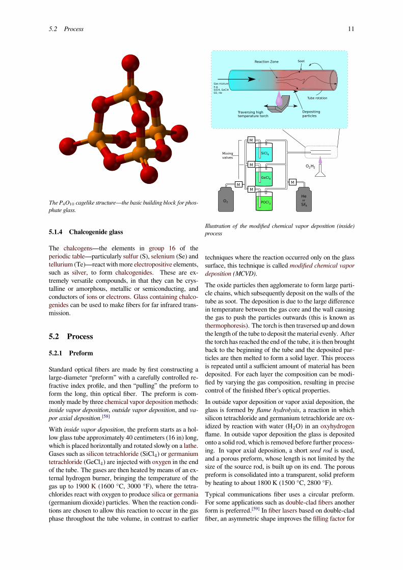
Cross-section of a fiber drawn from a D-shaped preform
laser pumping.Because of the surface tension, the shape is smoothedduring the drawing process, and the shape of the resultingfiber does not reproduce the sharp edges of the preform.Nevertheless, careful polishing of the preform is impor-tant, since any defects of the preform surface affect theoptical and mechanical properties of the resulting fiber.In particular, the preform for the test-fiber shown in thefigure was not polished well, and cracks are seen with theconfocal optical microscope.
5.2.2 Drawing
The preform, however constructed, is placed in a de-vice known as a drawing tower, where the preform tipis heated and the optical fiber is pulled out as a string.By measuring the resultant fiber width, the tension on thefiber can be controlled to maintain the fiber thickness.
5.3 Coatings
The light is guided down the core of the fiber by an opticalcladding with a lower refractive index that traps light inthe core through total internal reflection.The cladding is coated by a buffer that protects it frommoisture and physical damage.[47] The buffer coating iswhat gets stripped off the fiber for termination or splicing.These coatings are UV-cured urethane acrylate compos-ite materials applied to the outside of the fiber during thedrawing process. The coatings protect the very delicatestrands of glass fiber—about the size of a human hair—and allow it to survive the rigors of manufacturing, prooftesting, cabling and installation.Today’s glass optical fiber draw processes employ a dual-
layer coating approach. An inner primary coating is de-signed to act as a shock absorber to minimize attenua-tion caused by microbending. An outer secondary coat-ing protects the primary coating against mechanical dam-age and acts as a barrier to lateral forces. Sometimes ametallic armor layer is added to provide extra protection.These fiber optic coating layers are applied during thefiber draw, at speeds approaching 100 kilometers perhour (60 mph). Fiber optic coatings are applied usingone of two methods: wet-on-dry and wet-on-wet. In wet-on-dry, the fiber passes through a primary coating appli-cation, which is then UV cured—then through the sec-ondary coating application, which is subsequently cured.In wet-on-wet, the fiber passes through both the primaryand secondary coating applications, then goes to UV cur-ing.Fiber optic coatings are applied in concentric layers toprevent damage to the fiber during the drawing appli-cation and to maximize fiber strength and microbendresistance. Unevenly coated fiber will experience non-uniform forces when the coating expands or contracts,and is susceptible to greater signal attenuation. Underproper drawing and coating processes, the coatings areconcentric around the fiber, continuous over the lengthof the application and have constant thickness.Fiber optic coatings protect the glass fibers from scratchesthat could lead to strength degradation. The combinationof moisture and scratches accelerates the aging and dete-rioration of fiber strength. When fiber is subjected to lowstresses over a long period, fiber fatigue can occur. Overtime or in extreme conditions, these factors combine tocause microscopic flaws in the glass fiber to propagate,which can ultimately result in fiber failure.Three key characteristics of fiber optic waveguides can beaffected by environmental conditions: strength, attenua-tion and resistance to losses caused by microbending. Ex-ternal fiber optic coatings protect glass optical fiber fromenvironmental conditions that can affect the fiber’s per-formance and long-term durability. On the inside, coat-ings ensure the reliability of the signal being carried andhelp minimize attenuation due to microbending.
6 Practical issues
6.1 Cable construction
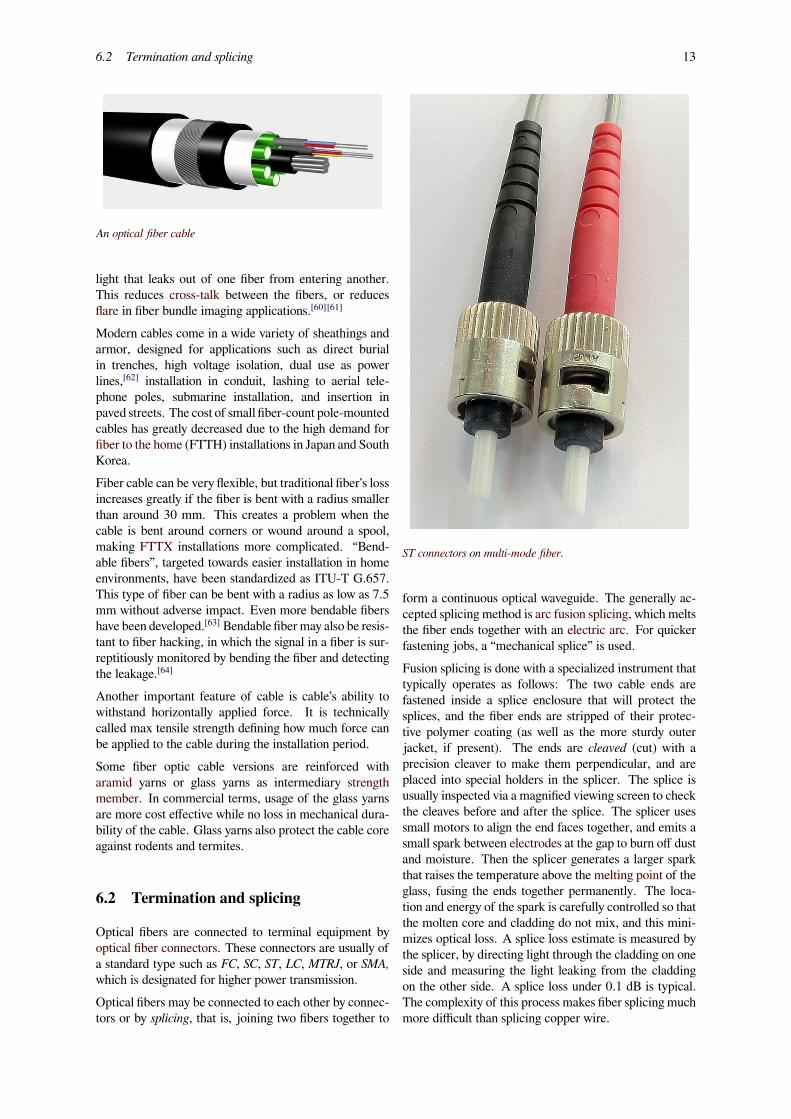
Main article: Optical fiber cable
In practical fibers, the cladding is usually coated with atough resin buffer layer, which may be further surroundedby a jacket layer, usually glass. These layers add strengthto the fiber but do not contribute to its optical wave guideproperties. Rigid fiber assemblies sometimes put light-absorbing (“dark”) glass between the fibers, to prevent
6.2 Termination and splicing 13
An optical fiber cable
light that leaks out of one fiber from entering another.This reduces cross-talk between the fibers, or reducesflare in fiber bundle imaging applications.[60][61]
Modern cables come in a wide variety of sheathings andarmor, designed for applications such as direct burialin trenches, high voltage isolation, dual use as powerlines,[62] installation in conduit, lashing to aerial tele-phone poles, submarine installation, and insertion inpaved streets. The cost of small fiber-count pole-mountedcables has greatly decreased due to the high demand forfiber to the home (FTTH) installations in Japan and SouthKorea.Fiber cable can be very flexible, but traditional fiber’s lossincreases greatly if the fiber is bent with a radius smallerthan around 30 mm. This creates a problem when thecable is bent around corners or wound around a spool,making FTTX installations more complicated. “Bend-able fibers”, targeted towards easier installation in homeenvironments, have been standardized as ITU-T G.657.This type of fiber can be bent with a radius as low as 7.5mm without adverse impact. Even more bendable fibershave been developed.[63] Bendable fibermay also be resis-tant to fiber hacking, in which the signal in a fiber is sur-reptitiously monitored by bending the fiber and detectingthe leakage.[64]
Another important feature of cable is cable’s ability towithstand horizontally applied force. It is technicallycalled max tensile strength defining how much force canbe applied to the cable during the installation period.Some fiber optic cable versions are reinforced witharamid yarns or glass yarns as intermediary strengthmember. In commercial terms, usage of the glass yarnsare more cost effective while no loss in mechanical dura-bility of the cable. Glass yarns also protect the cable coreagainst rodents and termites.
6.2 Termination and splicing
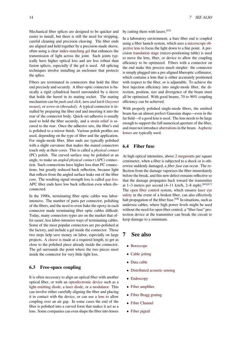
Optical fibers are connected to terminal equipment byoptical fiber connectors. These connectors are usually ofa standard type such as FC, SC, ST, LC, MTRJ, or SMA,which is designated for higher power transmission.Optical fibers may be connected to each other by connec-tors or by splicing, that is, joining two fibers together to
ST connectors on multi-mode fiber.
form a continuous optical waveguide. The generally ac-cepted splicing method is arc fusion splicing, which meltsthe fiber ends together with an electric arc. For quickerfastening jobs, a “mechanical splice” is used.Fusion splicing is done with a specialized instrument thattypically operates as follows: The two cable ends arefastened inside a splice enclosure that will protect thesplices, and the fiber ends are stripped of their protec-tive polymer coating (as well as the more sturdy outerjacket, if present). The ends are cleaved (cut) with aprecision cleaver to make them perpendicular, and areplaced into special holders in the splicer. The splice isusually inspected via a magnified viewing screen to checkthe cleaves before and after the splice. The splicer usessmall motors to align the end faces together, and emits asmall spark between electrodes at the gap to burn off dustand moisture. Then the splicer generates a larger sparkthat raises the temperature above the melting point of theglass, fusing the ends together permanently. The loca-tion and energy of the spark is carefully controlled so thatthe molten core and cladding do not mix, and this mini-mizes optical loss. A splice loss estimate is measured bythe splicer, by directing light through the cladding on oneside and measuring the light leaking from the claddingon the other side. A splice loss under 0.1 dB is typical.The complexity of this process makes fiber splicing muchmore difficult than splicing copper wire.
14 7 SEE ALSO
Mechanical fiber splices are designed to be quicker andeasier to install, but there is still the need for stripping,careful cleaning and precision cleaving. The fiber endsare aligned and held together by a precision-made sleeve,often using a clear index-matching gel that enhances thetransmission of light across the joint. Such joints typ-ically have higher optical loss and are less robust thanfusion splices, especially if the gel is used. All splicingtechniques involve installing an enclosure that protectsthe splice.Fibers are terminated in connectors that hold the fiberend precisely and securely. A fiber-optic connector is ba-sically a rigid cylindrical barrel surrounded by a sleevethat holds the barrel in its mating socket. The matingmechanism can be push and click, turn and latch (bayonetmount), or screw-in (threaded). A typical connector is in-stalled by preparing the fiber end and inserting it into therear of the connector body. Quick-set adhesive is usuallyused to hold the fiber securely, and a strain relief is se-cured to the rear. Once the adhesive sets, the fiber’s endis polished to a mirror finish. Various polish profiles areused, depending on the type of fiber and the application.For single-mode fiber, fiber ends are typically polishedwith a slight curvature that makes the mated connectorstouch only at their cores. This is called a physical contact(PC) polish. The curved surface may be polished at anangle, to make an angled physical contact (APC) connec-tion. Such connections have higher loss than PC connec-tions, but greatly reduced back reflection, because lightthat reflects from the angled surface leaks out of the fibercore. The resulting signal strength loss is called gap loss.APC fiber ends have low back reflection even when dis-connected.In the 1990s, terminating fiber optic cables was labor-intensive. The number of parts per connector, polishingof the fibers, and the need to oven-bake the epoxy in eachconnector made terminating fiber optic cables difficult.Today, many connectors types are on the market that of-fer easier, less labor-intensive ways of terminating cables.Some of the most popular connectors are pre-polished atthe factory, and include a gel inside the connector. Thosetwo steps help save money on labor, especially on largeprojects. A cleave is made at a required length, to get asclose to the polished piece already inside the connector.The gel surrounds the point where the two pieces meetinside the connector for very little light loss.
6.3 Free-space coupling
It is often necessary to align an optical fiber with anotheroptical fiber, or with an optoelectronic device such as alight-emitting diode, a laser diode, or a modulator. Thiscan involve either carefully aligning the fiber and placingit in contact with the device, or can use a lens to allowcoupling over an air gap. In some cases the end of thefiber is polished into a curved form that makes it act as alens. Some companies can even shape the fiber into lenses
by cutting them with lasers.[65]
In a laboratory environment, a bare fiber end is coupledusing a fiber launch system, which uses a microscope ob-jective lens to focus the light down to a fine point. A pre-cision translation stage (micro-positioning table) is usedto move the lens, fiber, or device to allow the couplingefficiency to be optimized. Fibers with a connector onthe end make this process much simpler: the connectoris simply plugged into a pre-aligned fiberoptic collimator,which contains a lens that is either accurately positionedwith respect to the fiber, or is adjustable. To achieve thebest injection efficiency into single-mode fiber, the di-rection, position, size and divergence of the beam mustall be optimized. With good beams, 70 to 90% couplingefficiency can be achieved.With properly polished single-mode fibers, the emittedbeam has an almost perfect Gaussian shape—even in thefar field—if a good lens is used. The lens needs to be largeenough to support the full numerical aperture of the fiber,and must not introduce aberrations in the beam. Asphericlenses are typically used.
6.4 Fiber fuse
At high optical intensities, above 2 megawatts per squarecentimeter, when a fiber is subjected to a shock or is oth-erwise suddenly damaged, a fiber fuse can occur. The re-flection from the damage vaporizes the fiber immediatelybefore the break, and this new defect remains reflective sothat the damage propagates back toward the transmitterat 1–3 meters per second (4–11 km/h, 2–8 mph).[66][67]The open fiber control system, which ensures laser eyesafety in the event of a broken fiber, can also effectivelyhalt propagation of the fiber fuse.[68] In situations, such asundersea cables, where high power levels might be usedwithout the need for open fiber control, a “fiber fuse” pro-tection device at the transmitter can break the circuit tokeep damage to a minimum.
7 See also• Borescope
• Cable jetting
• Data cable
• Distributed acoustic sensing
• Endoscopy
• Fiber amplifier
• Fiber Bragg grating
• Fibre Channel
• Fiber pigtail
Top Related