


Languages
Pages
Legal

TechnicalPublications
Third Edition, First PrintingPart No. 35054
Operator'sManual
® IWP
Genie IWP Part No. 35054
Operator’s Manual Third Edition
Copyright © 1993 by Genie Industries.
First Edition: First Printing, February 1993Second Printing, August 1993Third Printing, June 1994
Second Edition: First Printing, July 1994
Third Edition: First Printing, April, 1995
Genie® is a registered trademark ofGenie Industries. Registered 2009987.
This machine complies withANSI/SIA A92.3-1990.
Printed on recycled paper.
Printed in U.S.A.
U.S. Patent No. 5,337,858
®
Important
Read, understand and obey these safety rules andoperating instructions before operating this machine.Only trained and authorized personnel shall bepermitted to operate this machine. This manual isconsidered a permanent part of your machine andshould remain with the machine at all times. If youhave any questions, call Genie Industries.
Contents
PageSafety Rules .............................................................. 1Controls ..................................................................... 6Legend ...................................................................... 7Pre-operation Inspection............................................ 8Function Tests .......................................................... 10Workplace Inspection ............................................... 12Operating Instructions .............................................. 13Battery and Charger Instructions .............................. 14Decals ...................................................................... 16Transport Instructions ............................................... 19Specifications ........................................................... 20
Genie North AmericaTelephone (206) 881-1800Toll Free in U.S.A. 800 536-1800Toll Free in Canada 800 426-8089Fax (206) 883-3475
Genie EuropeTelephone (44) 01636-605030Fax (44) 01636-611090
®
� �� ����� � �
Operator’s ManualThird Edition
Safety Rules
Warning
Failure to obey the instructions andsafety rules in this manual will resultin death or serious injury.
Do Not Operate Unless:
You learn and practice the principles of safemachine operation contained in this operator'smanual.
1 Avoid hazardous situations.
Know and understand the above principlebefore going on to the next section.
2 Always perform a pre-operationinspection.
3 Always perform the function tests prior touse.
4 Inspect the workplace.
5 Only use the machine as a personnel lift.
You read, understand and obey:
manufacturer's instructions and safetyrules—operator's manual and machinedecals
employer's safety rules and worksiteregulations
applicable governmental regulations
� � � �� �����
Operator’s Manual Third Edition
SAFETY RULES
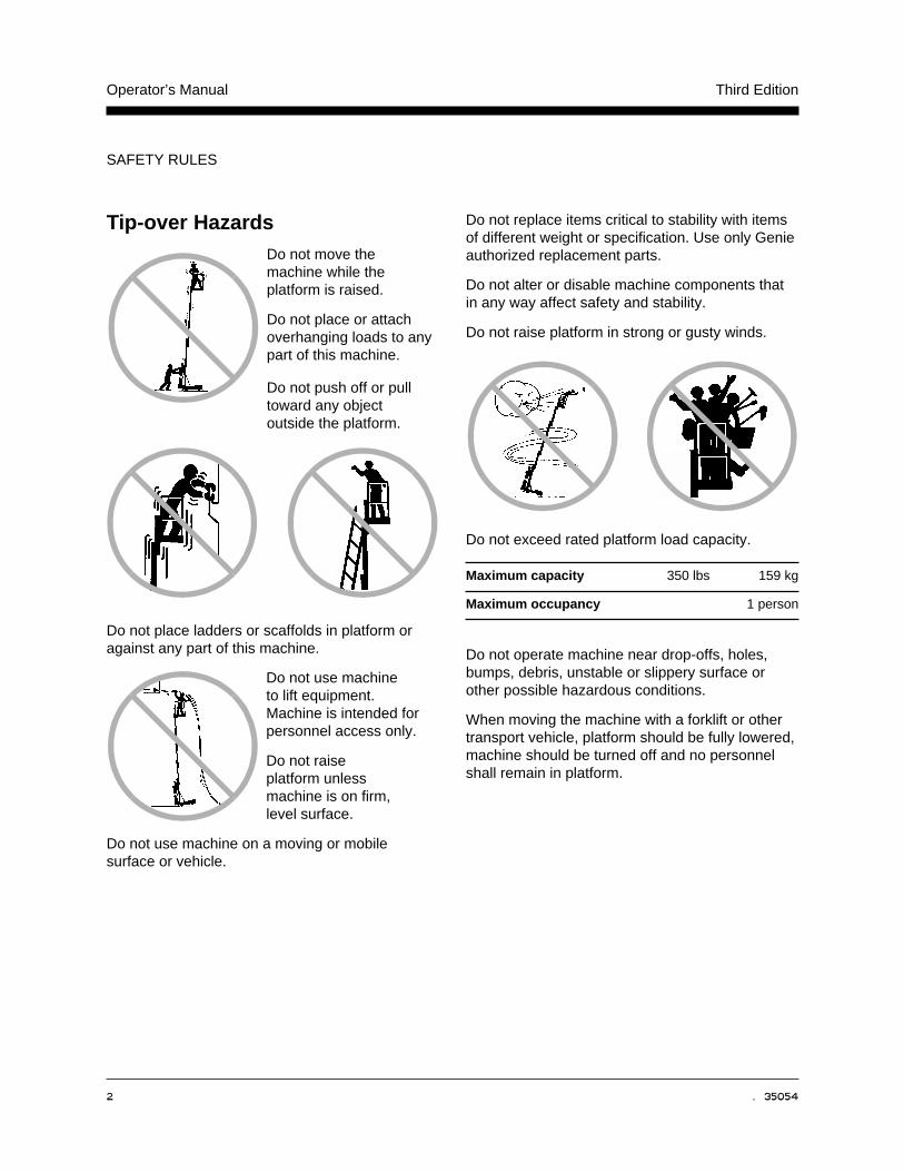
Tip-over HazardsDo not move themachine while theplatform is raised.
Do not place or attachoverhanging loads to anypart of this machine.
Do not push off or pulltoward any objectoutside the platform.
Do not place ladders or scaffolds in platform oragainst any part of this machine.
Do not use machineto lift equipment.Machine is intended forpersonnel access only.
Do not raiseplatform unlessmachine is on firm,level surface.
Do not use machine on a moving or mobilesurface or vehicle.
Do not replace items critical to stability with itemsof different weight or specification. Use only Genieauthorized replacement parts.
Do not alter or disable machine components thatin any way affect safety and stability.
Do not raise platform in strong or gusty winds.
Do not exceed rated platform load capacity.
Maximum capacity 350 lbs 159 kg
Maximum occupancy 1 person
Do not operate machine near drop-offs, holes,bumps, debris, unstable or slippery surface orother possible hazardous conditions.
When moving the machine with a forklift or othertransport vehicle, platform should be fully lowered,machine should be turned off and no personnelshall remain in platform.
� �� ����� � �
Operator’s ManualThird Edition
SAFETY RULES
Maintain safe distances from electrical power linesand apparatus in accordance with applicablegovernmental regulations and the following chart.
Voltage Minimum SafeApproach Distance
Phase to Phase Feet Meters
0 to 300V Avoid Contact
300V to 50KV 10 3.05
50KV to 200KV 15 4.60
200KV to 350KV 20 6.10
350KV to 500KV 25 7.62
500KV to 750KV 35 10.67
750KV to 1000KV 45 13.72
Allow for platform movement, electrical linesway or sag and movement due to strong orgusty winds.
Do not use machine as a ground for welding.
Do not operate AC powered machine orDC battery charger unless using a 3-wiregrounded extension cord connected to agrounded AC circuit. Do not alter or disable3-wire grounded plugs.
Improper Use HazardDo not leave machine unattended unless key isremoved to secure from unauthorized use.
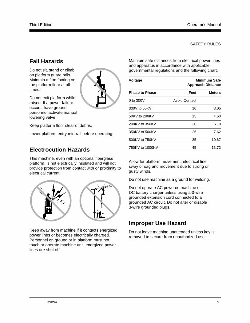
Fall HazardsDo not sit, stand or climbon platform guard rails.Maintain a firm footing onthe platform floor at alltimes.
Do not exit platform whileraised. If a power failureoccurs, have groundpersonnel activate manuallowering valve.
Keep platform floor clear of debris.
Lower platform entry mid-rail before operating.
Electrocution HazardsThis machine, even with an optional fiberglassplatform, is not electrically insulated and will notprovide protection from contact with or proximity toelectrical current.
Keep away from machine if it contacts energizedpower lines or becomes electrically charged.Personnel on ground or in platform must nottouch or operate machine until energized powerlines are shut off.
� � � �� �����
Operator’s Manual Third Edition
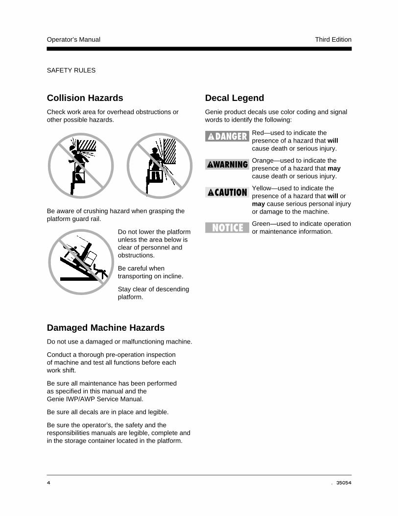
Collision HazardsCheck work area for overhead obstructions orother possible hazards.
Be aware of crushing hazard when grasping theplatform guard rail.
Do not lower the platformunless the area below isclear of personnel andobstructions.
Be careful whentransporting on incline.
Stay clear of descendingplatform.
Damaged Machine HazardsDo not use a damaged or malfunctioning machine.
Conduct a thorough pre-operation inspectionof machine and test all functions before eachwork shift.
Be sure all maintenance has been performedas specified in this manual and theGenie IWP/AWP Service Manual.
Be sure all decals are in place and legible.
Be sure the operator’s, the safety and theresponsibilities manuals are legible, complete andin the storage container located in the platform.
SAFETY RULES
Decal LegendGenie product decals use color coding and signalwords to identify the following:
Red—used to indicate thepresence of a hazard that willcause death or serious injury.
Orange—used to indicate thepresence of a hazard that maycause death or serious injury.
Yellow—used to indicate thepresence of a hazard that will ormay cause serious personal injuryor damage to the machine.
Green—used to indicate operationor maintenance information.
� �� ����� � �
Operator’s ManualThird Edition
SAFETY RULES
Battery and Charger Safety -DC Models
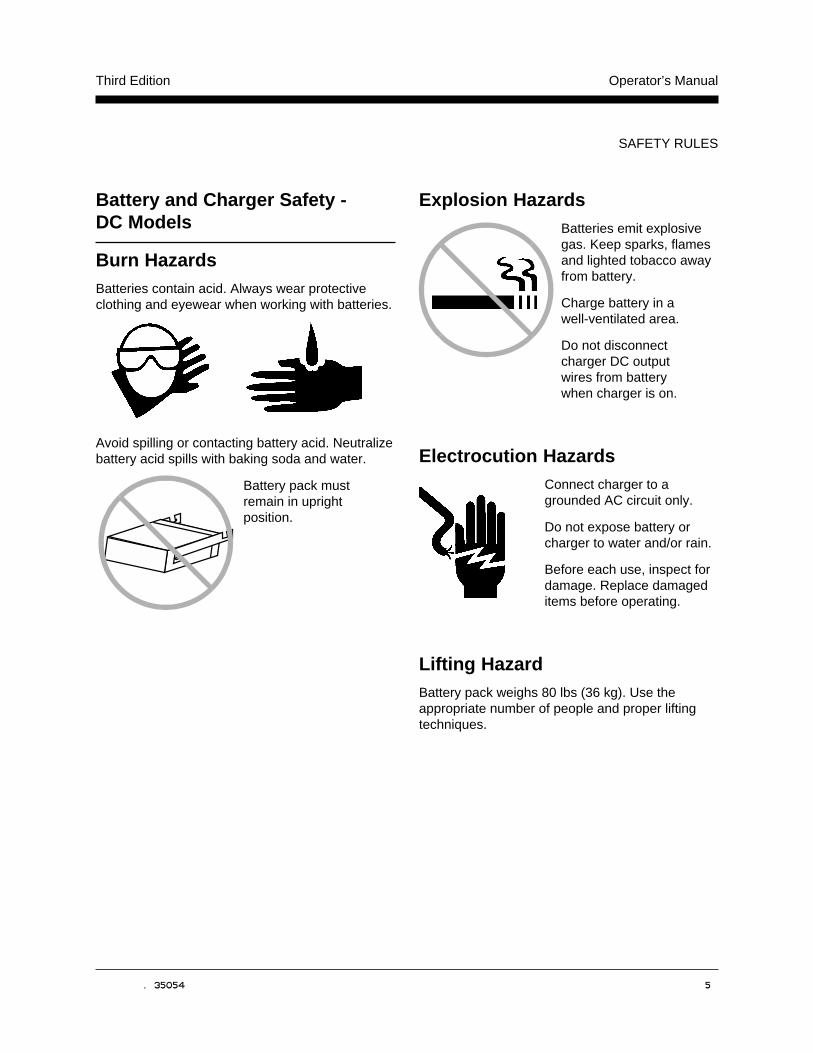
Burn HazardsBatteries contain acid. Always wear protectiveclothing and eyewear when working with batteries.
Avoid spilling or contacting battery acid. Neutralizebattery acid spills with baking soda and water.
Battery pack mustremain in uprightposition.
Explosion HazardsBatteries emit explosivegas. Keep sparks, flamesand lighted tobacco awayfrom battery.
Charge battery in awell-ventilated area.
Do not disconnectcharger DC outputwires from batterywhen charger is on.
Electrocution HazardsConnect charger to agrounded AC circuit only.
Do not expose battery orcharger to water and/or rain.
Before each use, inspect fordamage. Replace damageditems before operating.
Lifting HazardBattery pack weighs 80 lbs (36 kg). Use theappropriate number of people and proper liftingtechniques.
6 Genie IWP Part No. 35054
Operator’s Manual Third Edition
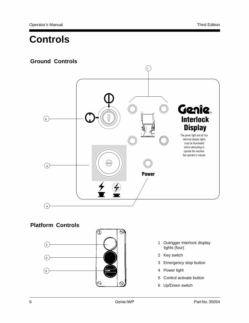
Controls
Ground Controls
Platform Controls
1 Outrigger interlock displaylights (four)
2 Key switch
3 Emergency stop button
4 Power light
5 Control activate button
6 Up/Down switch
�
�
�
�
�
�
�
Part No. 35054 Genie IWP 7
Operator’s ManualThird Edition
1 7 8 9 10 11 1 2 12
13
72324
8
9
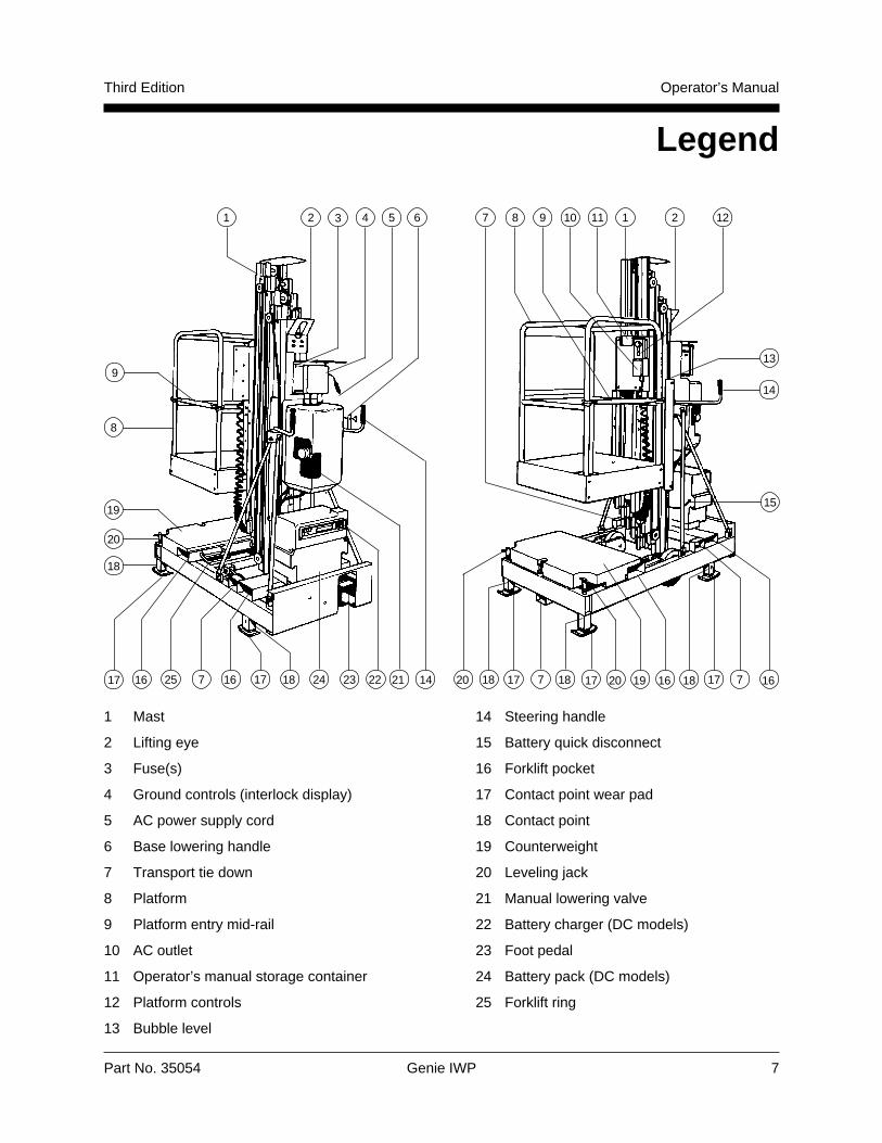
Legend
1616
19
2 3 54
14
15
1820 17 19187
18
17 16 25 7 16 17 18 21
6
1422
20
18 17 20 17
1 Mast
2 Lifting eye
3 Fuse(s)
4 Ground controls (interlock display)
5 AC power supply cord
6 Base lowering handle
7 Transport tie down
8 Platform
9 Platform entry mid-rail
10 AC outlet
11 Operator’s manual storage container
12 Platform controls
13 Bubble level
14 Steering handle
15 Battery quick disconnect
16 Forklift pocket
17 Contact point wear pad
18 Contact point
19 Counterweight
20 Leveling jack
21 Manual lowering valve
22 Battery charger (DC models)
23 Foot pedal
24 Battery pack (DC models)
25 Forklift ring

8 Genie IWP Part No. 35054
Operator’s Manual Third Edition
Pre-operation Inspection
Do Not Operate Unless:
You learn and practice the principles of safemachine operation contained in this operator'smanual.
1 Avoid hazardous situations.
2 Always perform a pre-operation inspection.
Know and understand the above principlebefore going on to the next section.
3 Always perform function tests prior to use.
4 Inspect the work place.
5 Only use the machine as a personnel lift.
FundamentalsThe Pre-operation Inspection is a visual inspectionperformed by the operator prior to each work shift.This inspection is designed to discover if anythingis apparently wrong with a machine before theoperator tests it.
Inspect the machine for modifications, damage orloose or missing parts.
A damaged or modified machine must never beused. If damage or any variation from factorydelivered condition is discovered, the machinemust be tagged and removed from service.
Repairs to the machine may only be made by aqualified service technician, according to themanufacturer's specifications. After repairs arecompleted, the operator must perform a pre-operation inspection again before testingfunctions.
Breather CapsComponent damage will occur if the machineis operated without both breather caps.
The first time thismachine is set up for use,the pipe plug in bothhydraulic reservoirsshould be removed andpermanently replacedwith breather caps.
Two breather caps aresupplied and can befound in an envelopetaped to the mast nearthe platform controls.
Part No. 35054 Genie IWP 9
Operator’s ManualThird Edition
PRE-OPERATION INSPECTION
Pre-operation Inspection
� Be sure that the operator’s, the safety and theresponsibilities manuals are complete, legibleand in the storage container located on themast.
� Be sure that all decals are legible and in place(see Decals, page 17).
Check the following components or areas fordamage and improperly installed, loose or missingparts:
� Electrical components, wiring and electricalcables
� Hydraulic power unit, hoses, fittings andcylinders
� Hydraulic manifolds and foot pump
� Platform entry mid-rail
� Sequencing cables and pulleys
� Lifting chains and idler wheels
� Mast columns and counterweight
� Nuts, bolts and other fasteners
� Breather caps
� Contact point wear pads
Check entire machine for:
� Dents or damage
� Corrosion or oxidation
� Cracks in welds or structural components
� Be sure that all structural and other criticalcomponents are present and all associatedfasteners and pins are in place and properlytightened.
10 Genie IWP Part No. 35054
Operator’s Manual Third Edition
Function Tests
Do Not Operate Unless:
You learn and practice the principles of safemachine operation contained in this operator'smanual.
1 Avoid hazardous situations.
2 Always perform a pre-operation inspection.
3 Always perform function tests prior to use.
Know and understand the above principlebefore going on to the next section.
4 Inspect the work place.
5 Only use the machine as a personnel lift.
Fundamentals
The Function Tests are designed to discover anymalfunctions before the machine is put intoservice. The operator must follow the step-by-stepinstructions to test all machine functions.
A malfunctioning machine must never be used. Ifmalfunctions are discovered, the machine must betagged and removed from service. Repairs to themachine may only be made by a qualified servicetechnician, according to the manufacturer'sspecifications.
After repairs are completed, the operator mustperform a pre-operation inspection and functiontests again before putting the machine into service.
Function Tests
1 Select a level test area free of obstructions.
2 Pump the foot pedal to raise the base.
Result: The wheels should contact the ground.
3 Pull base lowering handle to fully lowerthe base.
Result: All four contact points should come infirm contact with the ground.
Test Interlock System
4 Connect the appropriate power source.
5 Insert the key and turn to the ON position.
6 Pull out the red Emergency Stop button to theON position.
Result: The power light should come on.
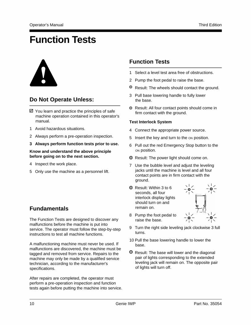
7 Use the bubble level and adjust the levelingjacks until the machine is level and all fourcontact points are in firm contact with theground.
Result: Within 3 to 6seconds, all fourinterlock display lightsshould turn on andremain on.
8 Pump the foot pedal toraise the base.
9 Turn the right side leveling jack clockwise 3 fullturns.
10 Pull the base lowering handle to lower thebase.
Result: The base will lower and the diagonalpair of lights corresponding to the extendedleveling jack will remain on. The opposite pairof lights will turn off.
Part No. 35054 Genie IWP 11
Operator’s ManualThird Edition
FUNCTION TESTS
11 Pump the foot pedal to raise the base.
12 Turn the right side leveling jackcounterclockwise 3 full turns. Then turn the lefthand leveling jack clockwise 3 full turns.
13 Pull the base lowering handle to lower thebase.
Result: The base will lower and the diagonalpair of lights corresponding to the extendedleveling jack will remain on. The opposite pairof lights will turn off.
14 Pump the foot pedal to raise the base.
15 Turn both the leveling jacks clockwise to the fulldown position.
16 Pull the base lowering handle to lower thebase.
Result: The base will lower and all four interlockdisplay lights should be off and remain offbecause the base is not level. The lights mayremain on for 2 to 3 seconds after lowering thebase, then turn off.
17 Twist to release the red Emergency Stop buttonat the platform controls.
18 Push in the control activate button and rotate tothe UP position, then the DOWN position.
Result: Platform up function should notoperate.
Test Emergency Stop
19 Use the bubble level and adjust the levelingjacks until the machine base is level. Be sureall four interlock display lights are on.
20 Push in the red Emergency Stop button at theground controls.
21 Push in the control activate button and rotatethe up/down switch in each direction.
Result: The platform up/down function shouldnot operate.
22 Push in the red Emergency Stop button at theplatform controls. Then pull out the redEmergency Stop button at the ground controls.
23 Push in the control activate button and rotatethe up/down switch in each direction.
Result: The platform up/down function shouldnot operate.
Test Manual Lowering
24 Twist to release the red Emergency Stop buttonat the platform controls. Confirm that the fiveground control display lights are on.
25 Push in the control activate button and rotatethe up/down switch to the UP position to raisethe platform approximately6 inches (15 cm).
26 Activate the manual lowering valve located onthe hydraulic power unit.
Result: Platform should lower.
Test Platform Raise and Lower
27 Push in the controlactivate button androtate the up/downswitch to the UP
position.
Result: Platformshould raisesmoothly, free ofhesitation.
28 Push in the control activate button and rotatethe up/down switch to the DOWN position.
Result: Platform should lower.
12 Genie IWP Part No. 35054
Operator's Manual Third Edition
Workplace Inspection
FundamentalsThe Work Place Inspection helps the operatordetermine if the work place is suitable for safemachine operation. It should be performed by theoperator prior to moving the machine to the workplace.
It is the operator's responsibility to read andremember the work place hazards, then watch forand avoid them while moving, setting up andoperating the machine.
Do Not Operate Unless:
You learn and practice the principles of safemachine operation contained in this operator'smanual.
1 Avoid hazardous situations.
2 Always perform a pre-operation inspection.
3 Always perform function tests prior to use.
4 Inspect the work place.
Know and understand the above principlebefore going on to the next section.
5 Only use the machine as a personnel lift.
Be aware of and avoid the following hazardoussituations:
· Drop-offs or holes
· Bumps and floor obstructions
· Debris
· Overhead obstructions and high voltageconductors
· Hazardous locations
· Inadequate surface support to withstand allload forces imposed by the machine
· Wind and weather conditions
· All other possible unsafe conditions
Part No. 35054 Genie IWP 13
Operator’s ManualThird Edition
Operating Instructions
Do Not Operate Unless:
You learn and practice the principles of safemachine operation contained in this operator'smanual.
1 Avoid hazardous situations.
2 Always perform a pre-operation inspection.
3 Always perform function tests prior to use.
4 Inspect the work place.
5 Only use the machine as a personnel lift.
FundamentalsUsing the machine for anything other than liftingpersonnel and tools to an aerial work site isunsafe.
If more than one operator is expected to use amachine at different times in the same work shift,each operator is expected to follow all safety rulesand instructions in the operator's manual. Thatmeans every new operator should perform a pre-operation inspection, function tests and a workplace inspection before using the machine.
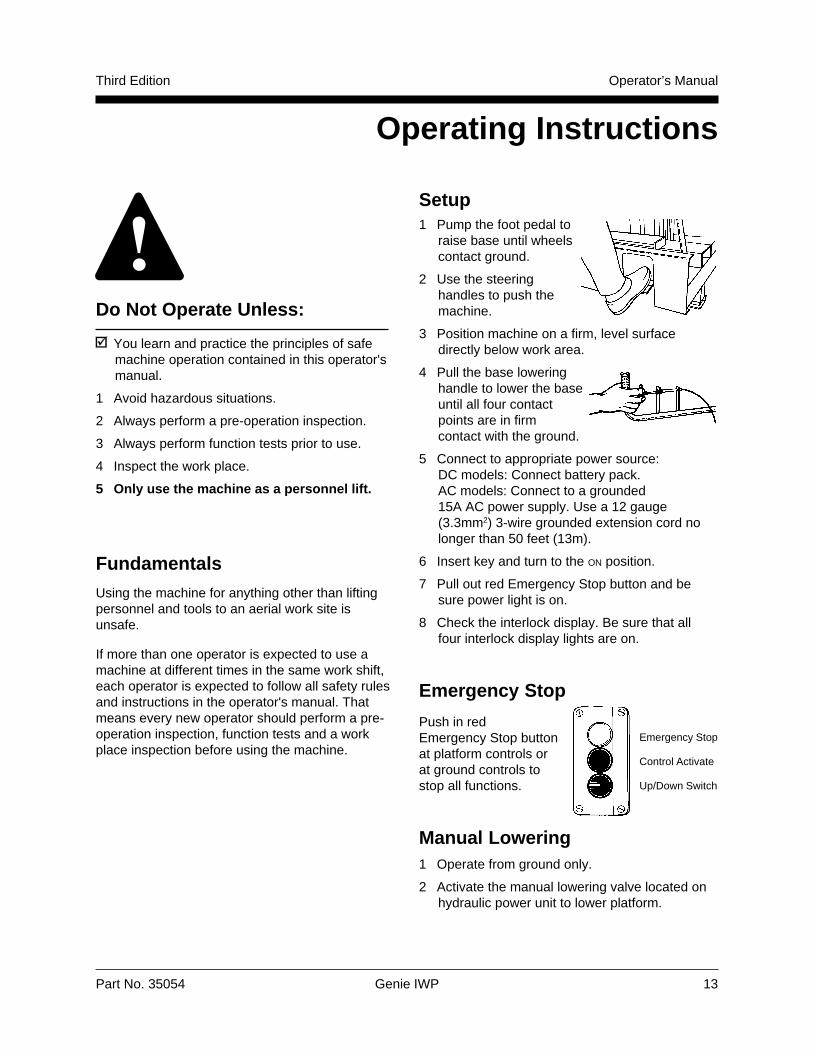
Setup1 Pump the foot pedal to
raise base until wheelscontact ground.
2 Use the steeringhandles to push themachine.
3 Position machine on a firm, level surfacedirectly below work area.
4 Pull the base loweringhandle to lower the baseuntil all four contactpoints are in firmcontact with the ground.
5 Connect to appropriate power source:DC models: Connect battery pack.AC models: Connect to a grounded15A AC power supply. Use a 12 gauge(3.3mm2) 3-wire grounded extension cord nolonger than 50 feet (13m).
6 Insert key and turn to the ON position.
7 Pull out red Emergency Stop button and besure power light is on.
8 Check the interlock display. Be sure that allfour interlock display lights are on.
Emergency Stop
Push in redEmergency Stop buttonat platform controls orat ground controls tostop all functions.
Manual Lowering1 Operate from ground only.
2 Activate the manual lowering valve located onhydraulic power unit to lower platform.
Emergency Stop
Control Activate
Up/Down Switch
14 Genie IWP Part No. 35054
Operator’s Manual Third Edition
OPERATING INSTRUCTIONS
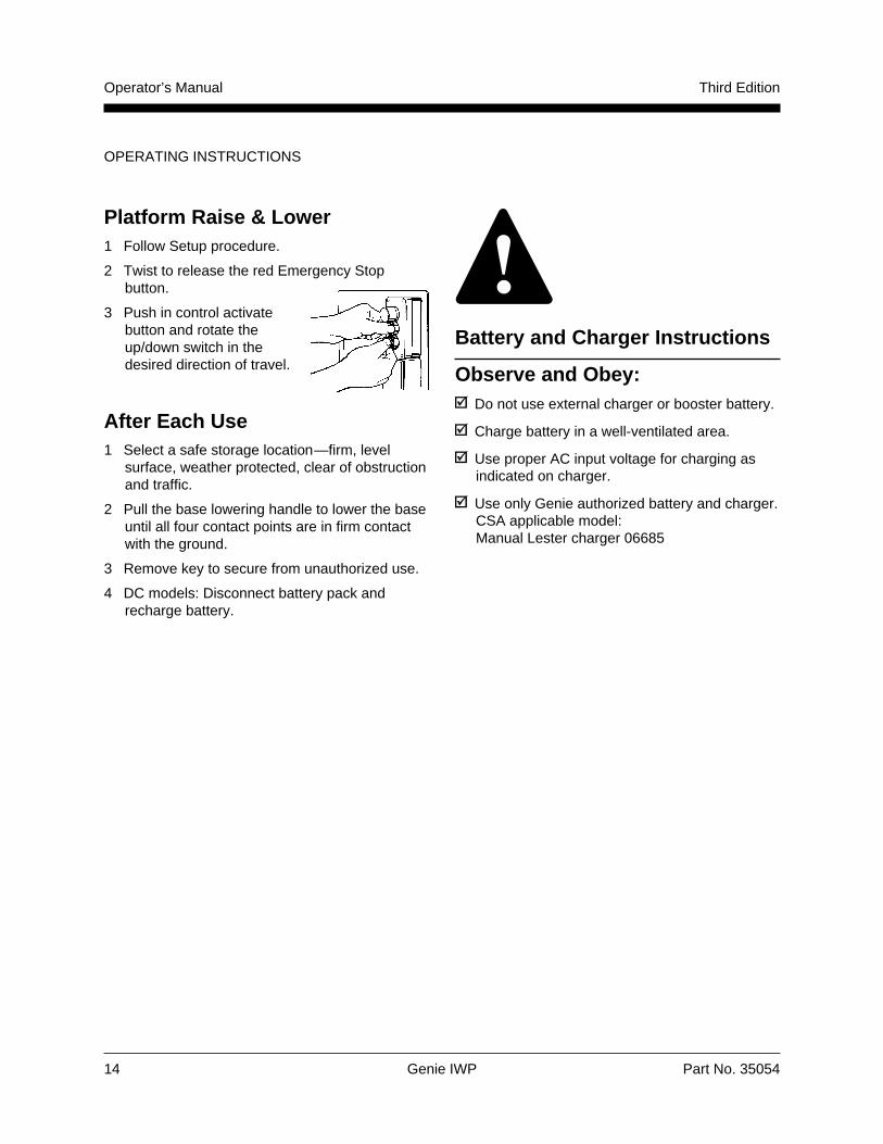
Platform Raise & Lower1 Follow Setup procedure.
2 Twist to release the red Emergency Stopbutton.
3 Push in control activatebutton and rotate theup/down switch in thedesired direction of travel.
After Each Use1 Select a safe storage location—firm, level
surface, weather protected, clear of obstructionand traffic.
2 Pull the base lowering handle to lower the baseuntil all four contact points are in firm contactwith the ground.
3 Remove key to secure from unauthorized use.
4 DC models: Disconnect battery pack andrecharge battery.
Battery and Charger Instructions
Observe and Obey:Do not use external charger or booster battery.
Charge battery in a well-ventilated area.
Use proper AC input voltage for charging asindicated on charger.
Use only Genie authorized battery and charger.CSA applicable model:Manual Lester charger 06685
Part No. 35054 Genie IWP 15
Operator’s ManualThird Edition
OPERATING INSTRUCTIONS
Dry Battery Filling andCharging Instructions1 Remove battery vent caps and permanently
remove plastic seal from battery vent openings.
2 Fill each cell with battery acid (electrolyte) untillevel is sufficient to cover plates.
Do not fill to maximum level until battery chargecycle is complete. Overfilling can cause the batteryacid to overflow during charging. Neutralizebattery acid spills with baking soda and water.
3 Install the vent caps.
4 Charge the battery.
5 Check the battery acid level when the chargingcycle is complete. Replenish with water to thebottom of the fill tube.
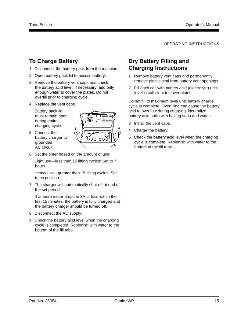
To Charge Battery1 Disconnect the battery pack from the machine.
2 Open battery pack lid to access battery.
3 Remove the battery vent caps and checkthe battery acid level. If necessary, add onlyenough water to cover the plates. Do notoverfill prior to charging cycle.
4 Replace the vent caps.
Battery pack lidmust remain openduring entirecharging cycle.
5 Connect thebattery charger togroundedAC circuit.
6 Set the timer based on the amount of use:
Light use—less than 15 lifting cycles: Set to 7hours.
Heavy use—greater than 15 lifting cycles: Setto ON position.
7 The charger will automatically shut off at end ofthe set period.
If ampere meter drops to 3A or less within thefirst 15 minutes, the battery is fully charged andthe battery charger should be turned off.
8 Disconnect the AC supply.
9 Check the battery acid level when the chargingcycle is completed. Replenish with water to thebottom of the fill tube.
16 Genie IWP Part No. 35054
Operator’s Manual Third Edition
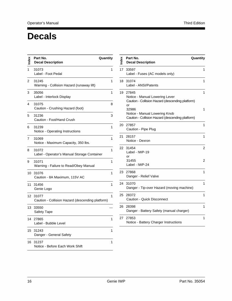
DecalsIn
dex Part No. Quantity
Decal Description
1 31073 1Label - Foot Pedal
2 31245 1Warning - Collision Hazard (runaway lift)
3 35056 1Label - Interlock Display
4 31075 8Caution - Crushing Hazard (foot)
5 31236 3Caution - Foot/Hand Crush
6 31239 1Notice - Operating Instructions
7 31069 1Notice - Maximum Capacity, 350 lbs.
8 31072 1Label - Operator’s Manual Storage Container
9 31071 1Warning - Failure to Read/Obey Manual
10 31076 1Caution - 8A Maximum, 115V AC
11 31456 1Genie Logo
12 31077 1Caution - Collision Hazard (descending platform)
13 33550 —Safety Tape
14 27865 1Label - Bubble Level
15 31243 1Danger - General Safety
16 31237 1Notice - Before Each Work Shift
Ind
ex Part No. QuantityDecal Description
17 33597 1Label - Fuses (AC models only)
18 31074 1Label - ANSI/Patents
19 27845 1Notice - Manual Lowering LeverCaution - Collision Hazard (descending platform)or32986 1Notice - Manual Lowering KnobCaution - Collision Hazard (descending platform)
20 27857 1Caution - Pipe Plug
21 28157 1Notice - Dexron
22 31454 2Label - IWP-19or31455 2Label - IWP-24
23 27868 1Danger - Relief Valve
24 31070 1Danger - Tip-over Hazard (moving machine)
25 28372 1Caution - Quick Disconnect
26 28398 1Danger - Battery Safety (manual charger)
27 27853 1Notice - Battery Charger Instructions
Part No. 35054 Genie IWP 17
Operator’s ManualThird Edition
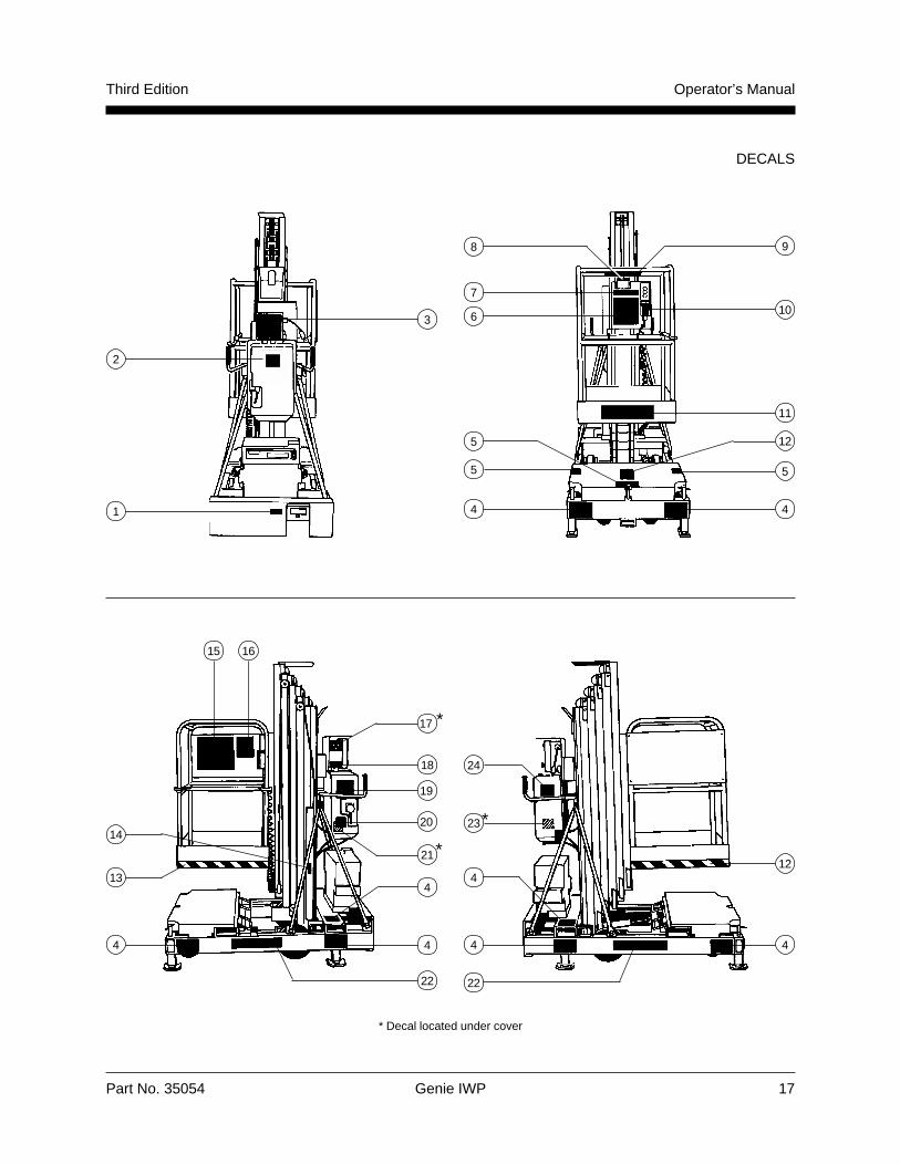
DECALS
1
2
3
5
4
5
4
8 9
10
5
7
6
4
21
23
4
*
4 4
4
24
*
18
1312
2222
1420
19
17
1615
* Decal located under cover
4
*
11
12
18 Genie IWP Part No. 35054
Operator’s Manual Third Edition
DECALS
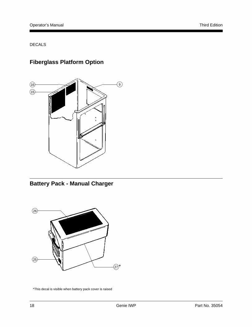
Fiberglass Platform Option
16
15
9
Battery Pack - Manual Charger
26
25
*This decal is visible when battery pack cover is raised
27 *
Part No. 35054 Genie IWP 19
Operator’s ManualThird Edition
Observe and Obey:Common sense and planning must be appliedto control the movement of the machine whenlifting it with a crane or forklift.
Transport vehicle must be parked on a levelsurface.
Transport vehicle must be secured to preventrolling while machine is being loaded.
Vehicle capacity, loading equipment andsurfaces must be capable of supportingmachine weight (see Specifications, page 20).
The base of the machine must remain fullylowered during all loading and transportprocedures.
The machine must be secured to the transportvehicle with chains or straps of ample loadcapacity.
Transport Instructions
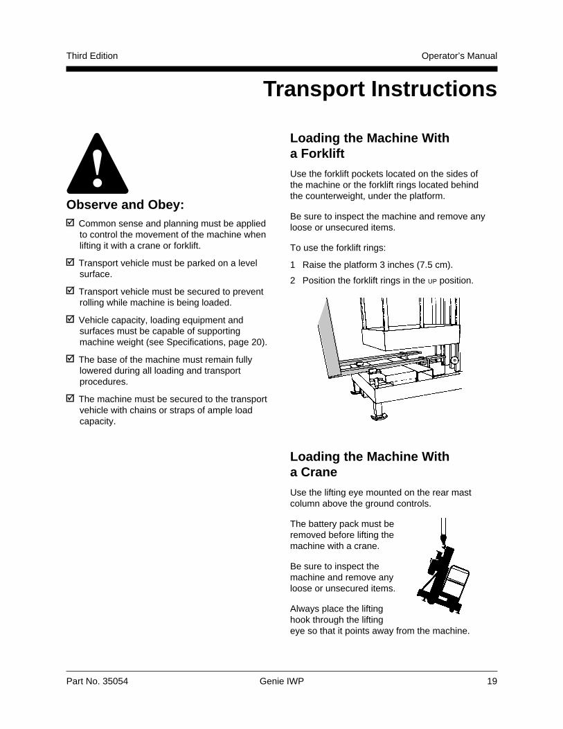
Loading the Machine Witha ForkliftUse the forklift pockets located on the sides ofthe machine or the forklift rings located behindthe counterweight, under the platform.
Be sure to inspect the machine and remove anyloose or unsecured items.
To use the forklift rings:
1 Raise the platform 3 inches (7.5 cm).
2 Position the forklift rings in the UP position.
Loading the Machine Witha Crane
Use the lifting eye mounted on the rear mastcolumn above the ground controls.
The battery pack must beremoved before lifting themachine with a crane.
Be sure to inspect themachine and remove anyloose or unsecured items.
Always place the liftinghook through the liftingeye so that it points away from the machine.
20 Genie IWP Part No. 35054
Operator’s Manual Third Edition
Model IWP-19 IWP-24
Height, working maximum 25 ft 4 in 29 ft 10 in7.7 m 9.1 m
Height, platform maximum 19 ft 4 in 23 ft 10 in5.8 m 7.2 m
Lift capacity 350 lbs 350 lbs159 kg 159 kg
Power sourceDC model 12V 12VAC model 110V or 220V 110V or 220V
Machine weight 1111/1050 lbs 1311/1250 lbs(DC/AC models) 505/477 kg 596/568 kg
Height, stowed* 77 in/79 in 77 in/79 in195/200 cm 195/200 cm
Width 32 in 32 in81 cm 81 cm
Length 60 in 60 in152 cm 152cm
Platform length 26 in 26 in66 cm 66 cm
Platform width 26 in 26 in66 cm 66 cm
Platform height 43 in 43 in106 cm 106 cm
Corner access** 6 in 6 in15 cm 15 cm
Continuous improvement of our products is a Geniepolicy. Product specifications are subject to changewithout notice or obligation.
* Base lowered/base fully raised** Corner of platform top rail to corner of wall with
ability to rotate leveling jack handle.
Specifications

U.S.A.18340 NE 76th Street
P.O. Box 69
Redmond, Washington
98073-0069
EuropeBrunel Drive
Newark
Nottinghamshire
NG24 2EG England
Top Related