


Languages
Pages
Legal

POST HOLE DIGGERS
OPERATOR’S HANDBOOKAND SPARE PART’S LIST
SERIESBPBPO-MBPO-H


INDEX
RECOMMENDATIONS TO OWNERSWARRANTYINNOVATIONS1- EXPLANATORY NOTE2- COMPONENTS3- TECHNICAL CHARACTERISTICS4- TRACTOR COUPLING5- ADJUSTMENTS6- TRANSPORTATION7- MAINTENANCE8- REPLACEMENT OF THE PARTS WITH GREATEST WEAR9- CARDAN SHAFT TRANSMISSION10- SECURITY REGULATIONS11- ORDERING SPARE PARTSSPARE PART’S LIST
. . .
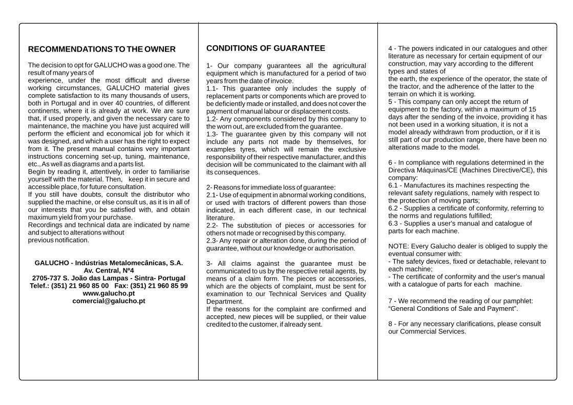
RECOMMENDATIONS TO THE OWNER
The decision to opt for GALUCHO was a good one. The result of many years ofexperience, under the most difficult and diverse working circumstances, GALUCHO material gives complete satisfaction to its many thousands of users, both in Portugal and in over 40 countries, of different continents, where it is already at work. We are sure that, if used properly, and given the necessary care to maintenance, the machine you have just acquired will perform the efficient and economical job for which it was designed, and which a user has the right to expect from it. The present manual contains very important instructions concerning set-up, tuning, maintenance, etc., As well as diagrams and a parts list.Begin by reading it, attentively, in order to familiarise yourself with the material. Then, keep it in secure and accessible place, for future consultation.If you still have doubts, consult the distributor who supplied the machine, or else consult us, as it is in all of our interests that you be satisfied with, and obtain maximum yield from your purchase.Recordings and technical data are indicated by name and subject to alterations withoutprevious notification.
GALUCHO - Indústrias Metalomecânicas, S.A.Av. Central, Nº4
2705-737 S. João das Lampas - Sintra- PortugalTelef.: (351) 21 960 85 00 Fax: (351) 21 960 85 99
CONDITIONS OF GUARANTEE
1- Our company guarantees all the agricultural equipment which is manufactured for a period of two years from the date of invoice.1.1- This guarantee only includes the supply of replacement parts or components which are proved to be deficiently made or installed, and does not cover the payment of manual labour or displacement costs.1.2- Any components considered by this company to the worn out, are excluded from the guarantee.1.3- The guarantee given by this company will not include any parts not made by themselves, for examples tyres, which will remain the exclusive responsibility of their respective manufacturer, and this decision will be communicated to the claimant with all its consequences.
2- Reasons for immediate loss of guarantee:2.1- Use of equipment in abnormal working conditions, or used with tractors of different powers than those indicated, in each different case, in our technical literature.2.2- The substitution of pieces or accessories for others not made or recognised by this company.2.3- Any repair or alteration done, during the period of guarantee, without our knowledge or authorisation.
3- All claims against the guarantee must be communicated to us by the respective retail agents, by means of a claim form. The pieces or accessories, which are the objects of complaint, must be sent for examination to our Technical Services and Quality Department.If the reasons for the complaint are confirmed and accepted, new pieces will be supplied, or their value credited to the customer, if already sent.
4 - The powers indicated in our catalogues and other literature as necessary for certain equipment of our construction, may vary according to the different types and states ofthe earth, the experience of the operator, the state of the tractor, and the adherence of the latter to the terrain on which it is working.5 - This company can only accept the return of equipment to the factory, within a maximum of 15 days after the sending of the invoice, providing it has not been used in a working situation, it is not a model already withdrawn from production, or if it is still part of our production range, there have been no alterations made to the model.
6 - In compliance with regulations determined in the Directiva Máquinas/CE (Machines Directive/CE), this company:6.1 - Manufactures its machines respecting the relevant safety regulations, namely with respect to the protection of moving parts;6.2 - Supplies a certificate of conformity, referring to the norms and regulations fulfilled;6.3 - Supplies a user's manual and catalogue of parts for each machine.
NOTE: Every Galucho dealer is obliged to supply the eventual consumer with:- The safety devices, fixed or detachable, relevant to each machine;- The certificate of conformity and the user's manual with a catalogue of parts for each machine.
7 - We recommend the reading of our pamphlet: “General Conditions of Sale and Payment”.
8 - For any necessary clarifications, please consult our Commercial Services.
Offset to the left
Offset to the right
In central position
Fig. 1
BPO-H
BP
MECHANICAL SPINDLE HEAD
HYDRAULIC SPINDLE HEAD
.
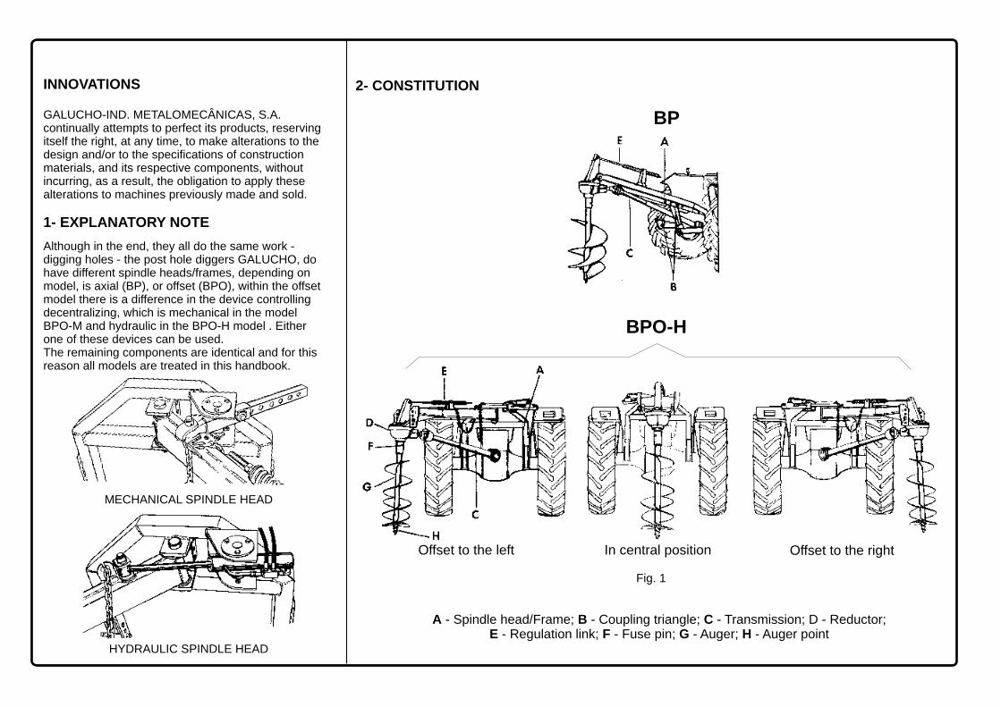
INNOVATIONS
GALUCHO-IND. METALOMECÂNICAS, S.A. continually attempts to perfect its products, reserving itself the right, at any time, to make alterations to the design and/or to the specifications of construction materials, and its respective components, without incurring, as a result, the obligation to apply these alterations to machines previously made and sold.
Although in the end, they all do the same work -digging holes - the post hole diggers GALUCHO, do have different spindle heads/frames, depending on model, is axial (BP), or offset (BPO), within the offset model there is a difference in the device controlling decentralizing, which is mechanical in the model BPO-M and hydraulic in the BPO-H model . Either one of these devices can be used.The remaining components are identical and for this reason all models are treated in this handbook.
1- EXPLANATORY NOTE
2- CONSTITUTION
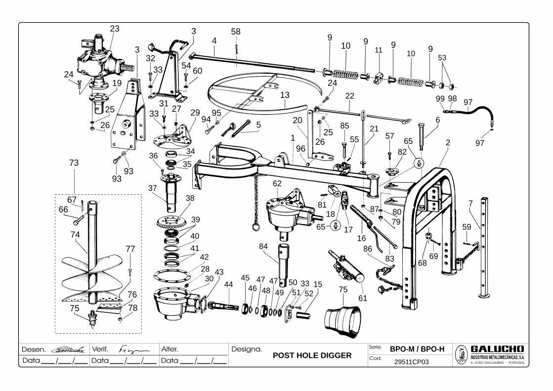
A - Spindle head/Frame; B - Coupling triangle; C - Transmission; D - Reductor; E - Regulation link; F - Fuse pin; G - Auger; H - Auger point
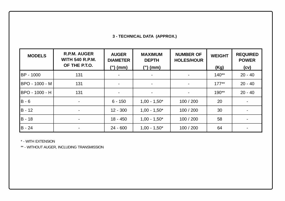
3 - TECHNICAL DATA (APPROX.)
AUGER MAXIMUM NUMBER OF REQUIRED
DIAMETER DEPTH HOLES/HOUR POWER
(”) (mm) (”) (mm) (Kg) (cv)
BP - 1000 131 - - - 140** 20 - 40
BPO - 1000 - M 131 - - - 177** 20 - 40
BPO - 1000 - H 131 - - - 190** 20 - 40
B - 6 - 6 - 150 1,00 - 1,50* 100 / 200 20 -
B - 12 - 12 - 300 1,00 - 1,50* 100 / 200 30 -
B - 18 - 18 - 450 1,00 - 1,50* 100 / 200 58 -
B - 24 - 24 - 600 1,00 - 1,50* 100 / 200 64 -
* - WITH EXTENSION
** - WITHOUT AUGER, INCLUDING TRANSMISSION
MODELS R.P.M. AUGER
WITH 540 R.P.M.
OF THE P.T.O.
WEIGHT
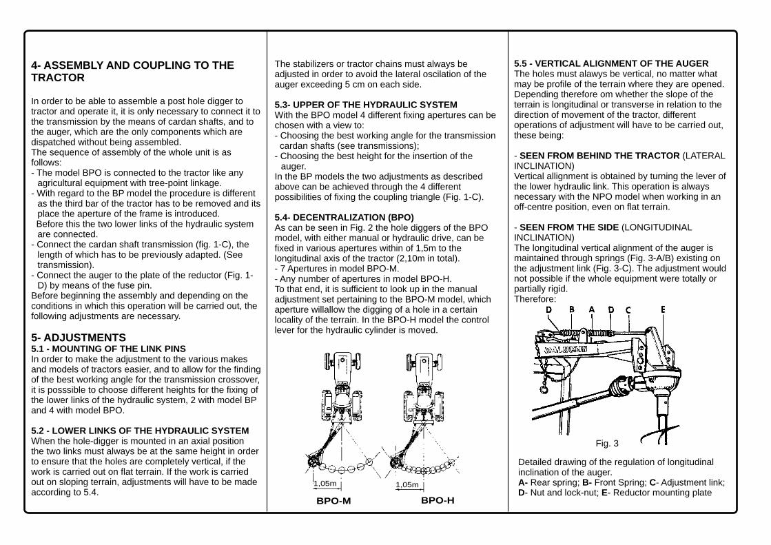
Fig. 3
4- ASSEMBLY AND COUPLING TO THETRACTOR
5- ADJUSTMENTS5.1 - MOUNTING OF THE LINK PINSIn order to make the adjustment to the various makesand models of tractors easier, and to allow for the finding of the best working angle for the transmission crossover, it is posssible to choose different heights for the fixing of the lower links of the hydraulic system, 2 with model BP and 4 with model BPO.
5.2 - LOWER LINKS OF THE HYDRAULIC SYSTEMWhen the hole-digger is mounted in an axial positionthe two links must always be at the same height in order to ensure that the holes are completely vertical, if the work is carried out on flat terrain. If the work is carried out on sloping terrain, adjustments will have to be made according to 5.4.
In order to be able to assemble a post hole digger to tractor and operate it, it is only necessary to connect it to the transmission by the means of cardan shafts, and to the auger, which are the only components which are dispatched without being assembled.The sequence of assembly of the whole unit is as follows:- The model BPO is connected to the tractor like any
agricultural equipment with tree-point linkage.- With regard to the BP model the procedure is different
as the third bar of the tractor has to be removed and its place the aperture of the frame is introduced.
Before this the two lower links of the hydraulic system are connected.
- Connect the cardan shaft transmission (fig. 1-C), the length of which has to be previously adapted. (See transmission).
- Connect the auger to the plate of the reductor (Fig. 1-D) by means of the fuse pin.
Before beginning the assembly and depending on the conditions in which this operation will be carried out, the following adjustments are necessary.
BPO-M
1,05m
1,05m
BPO-H
The stabilizers or tractor chains must always be adjusted in order to avoid the lateral oscilation of the auger exceeding 5 cm on each side.
5.3- UPPER OF THE HYDRAULIC SYSTEMWith the BPO model 4 different fixing apertures can be chosen with a view to:- Choosing the best working angle for the transmission
cardan shafts (see transmissions);- Choosing the best height for the insertion of the
auger.In the BP models the two adjustments as described above can be achieved through the 4 different possibilities of fixing the coupling triangle (Fig. 1-C).
5.4- DECENTRALIZATION (BPO)As can be seen in Fig. 2 the hole diggers of the BPO model, with either manual or hydraulic drive, can befixed in various apertures within of 1,5m to the longitudinal axis of the tractor (2,10m in total).- 7 Apertures in model BPO-M.- Any number of apertures in model BPO-H.To that end, it is sufficient to look up in the manual adjustment set pertaining to the BPO-M model, which aperture willallow the digging of a hole in a certain locality of the terrain. In the BPO-H model the control lever for the hydraulic cylinder is moved.
5.5 - VERTICAL ALIGNMENT OF THE AUGERThe holes must alawys be vertical, no matter what may be profile of the terrain where they are opened.Depending therefore om whether the slope of the terrain is longitudinal or transverse in relation to the direction of movement of the tractor, different operations of adjustment will have to be carried out, these being:
- SEEN FROM BEHIND THE TRACTOR (LATERAL INCLINATION)Vertical allignment is obtained by turning the lever of the lower hydraulic link. This operation is alwaysnecessary with the NPO model when working in an off-centre position, even on flat terrain.
- SEEN FROM THE SIDE (LONGITUDINAL INCLINATION)The longitudinal vertical alignment of the auger is maintained through springs (Fig. 3-A/B) existing onthe adjustment link (Fig. 3-C). The adjustment would not possible if the whole equipment were totally or partially rigid. Therefore:
Detailed drawing of the regulation of longitudinal inclination of the auger.A- Rear spring; B- Front Spring; C- Adjustment link; D- Nut and lock-nut; E- Reductor mounting plate
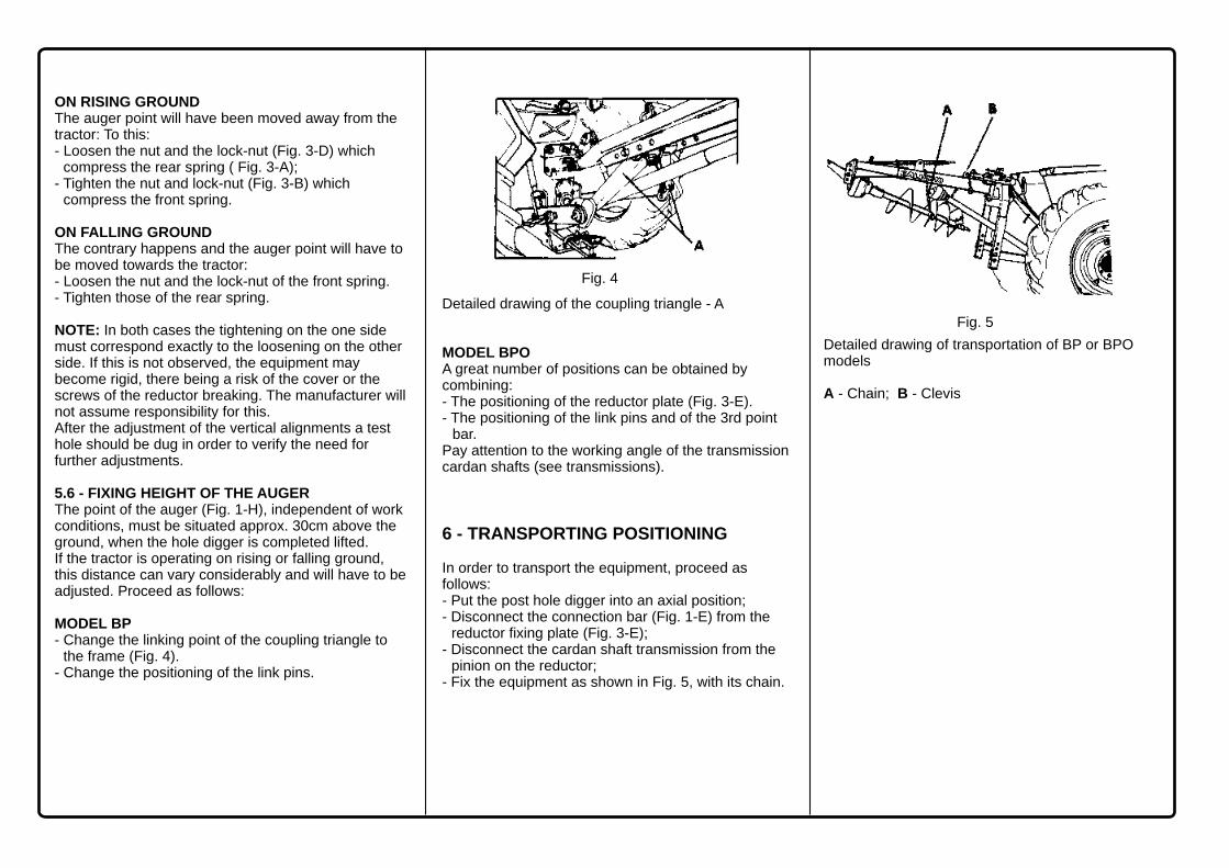
Fig. 4
Fig. 5
ON RISING GROUNDThe auger point will have been moved away from the tractor: To this:- Loosen the nut and the lock-nut (Fig. 3-D) which
compress the rear spring ( Fig. 3-A);- Tighten the nut and lock-nut (Fig. 3-B) which
compress the front spring.
ON FALLING GROUNDThe contrary happens and the auger point will have to be moved towards the tractor:- Loosen the nut and the lock-nut of the front spring.- Tighten those of the rear spring.
NOTE: In both cases the tightening on the one side must correspond exactly to the loosening on the other side. If this is not observed, the equipment may become rigid, there being a risk of the cover or the screws of the reductor breaking. The manufacturer will not assume responsibility for this.After the adjustment of the vertical alignments a test hole should be dug in order to verify the need for further adjustments.
5.6 - FIXING HEIGHT OF THE AUGERThe point of the auger (Fig. 1-H), independent of work conditions, must be situated approx. 30cm above the ground, when the hole digger is completed lifted.If the tractor is operating on rising or falling ground, this distance can vary considerably and will have to be adjusted. Proceed as follows: MODEL BP- Change the linking point of the coupling triangle to
the frame (Fig. 4).- Change the positioning of the link pins.
Detailed drawing of the coupling triangle - A
MODEL BPOA great number of positions can be obtained by combining: - The positioning of the reductor plate (Fig. 3-E).- The positioning of the link pins and of the 3rd point
bar.Pay attention to the working angle of the transmission cardan shafts (see transmissions).
6 - TRANSPORTING POSITIONING
In order to transport the equipment, proceed as follows:- Put the post hole digger into an axial position;- Disconnect the connection bar (Fig. 1-E) from the
reductor fixing plate (Fig. 3-E);- Disconnect the cardan shaft transmission from the
pinion on the reductor;- Fix the equipment as shown in Fig. 5, with its chain.
Detailed drawing of transportation of BP or BPO models
A - Chain; B - Clevis

7- MAINTENANCE
Before each working day:- Check and, if necessary, adjust the tightening of
screws and bolts;- In the BPO model, lubricate the pin where the frame
is borne by the spindle head. Apply lubricant EP grease 2 or equivalent in the grease nipple.
- Check the level of the gear reducer. Refill it if necessary;
- Lubricate the drive following the sketch indicated in the respective chapter;
- Check the state of wear of the shares and of the auger point (Fig. 6);
Each every 100 to 120 working hours:- Replace the oil in the reductor - use EP 90.
8 - REPLACEMENT OF THE PARTS WITH GREATEST WEAR
The parts which suffer most wear are the shares, the auger point and, eventually, the fuse pin.
- Shares (Fig. 6-B) They must be replaced before they are completely worn in order to avoid ruining their fixing points.There are two on each equipment, fixed with screws, and different for each diameter of the post hole digger.
- Auger point (Fig. 6-A) Loosen, turning to the left.It is the same for all diameters of post hole diggers.
- Fuse pin (Fig. 1-F) This is a calibrated pin which protects the equipment from excess of load. It is, therefore, possible that it will break.It must be replaced by a Galucho spare.
C B A B
Detailed drawing of the post hole digger
A- Auger point; B- Share; C- Screws
Fig. 6

BBC
D D
F
F
FG A
EEE E
A
B
8h 8h 8h40h 40h
8h
40h
8h 8h
40h
9- SHAFT TRANSMISSIONS
9.1- HOW TO ADJUST THE LENGTHTo avoid the risk of damaging the transmission, you should verify its length before coupling it to the tractor.Proceed as indicated:- Mount the equipment (without the transmission) on
the 3 point linkage and lift it up until the pinion shaft end stays at the same height
to the power take-off end;- Measure the exact distance between the coupling
cuts of the finger steering, which must be the same as that of the open circuit work measured between the finger steering, keeping a clearance of 15 to 20 mm.
- If necessary, cut the tube and the protection plate of both halves of the transmission, to get the desired length, keeping in mind the indicated clearance. The length of the tube and of the protection plate must be the same in each half transmission;
- After spruing, remove the filings, grease and Set up.
NOTE: Mind that, during operation, and with maximum opening, the internal and external tubes of the transmission should overlap at least half of their total length.
9.2- LINKING PROCEDUR- Clean the channels of the gear shift forks and the
splines of the power take-off shafts and of the pinion;- Make the channels coincide with the splines; tighten
up the finger steering or the crew in the respective channel and confirm if it is well fixed;
- Proceed the same way on the other extremity, verifying that the stop or the clutch should at stay on the same side as the implement.
- Check if the angle of each cardan shaft doesn't exceed 30°, in operation or in maximum raising. Consult the working tool's instruction book about how to link it on the tractor to obtain the desirable angle.
9.3 - EFFORT PROTECTION SYSTEMS - Depending on the models, every transmission has a
stop or a clutch to protect the machine against unusual efforts;
- If the screw (B) brakes, it should be replaced by an original one, calibrated;
- When the friction discs of the clutch are worn, they should be refined, spinning each one of the 8 nuts (A) 1/2 turn, until the desired adjustment is obtained. If the friction discs are totally worn down, they must be replaced immediately to avoid the damaging of the whole unit.
9.4- PROTECTION PANEL AGAINST ACCIDENTS- In no case should a transmission work without the protections, so as to prevent accidents. Fix the chains.- Extra protections should also be used on the PTO shaft on the tractor, and on the pinion shaft end.
9.5- LUBRICATION- Follow the scheme and the periodicity indicated on the figure, using a good quality grease. Clean the grease nipples before and after lubricating.
NOTE: Each transmission can only be used on the designed working tool, which varies according to the machine's horse power.
A - Sliding pins or finger steering; B - Cardan shaft; C - Clutch; D - Flexible hoses; E- Protective plates; F - Gear shift fork; G - Chain
CLUTCH CUT LIMITER
. . . . . .
10- SECURITY REGULATIONS
Working with tractors and agricultural machines requires that the operator knows what he is doing and that much care is taken. He must be conscious and cautious of the dangers which imprudence can cause, not just to the agricultural enterprises which they run. In an attempt to avoid accidents, therefore, we advise the following security rules:
1 - In attaching any implement to the tractor, use only the place which the respective manufacturer advised for the operation, verifying is carried out in order. .2 - Whenever, for reasons of repair, checks, set-up or otherwise, you need to get under the implement, never do so without the relevant props.
3 - In activating the hydraulic system of the tractor, first check that the implement, trailer, frontal load, or otherwise, in movement, can not reach anyone.
4 - Never authorise the transport of passengers on the implement, whether during work time or on the road, equally not behind ploughs, or grass cutters, as during their work, as stones, sticks etc. could fly up out of the machines. .5 - The implement should never be detached while in movement. If it has to be done, immobilise it well and stop the motor.
6 - Always use protective guards on transmissions linked to the power sockets of the tractor.
7 - Use counterweights on the front or on the front wheels, as, with implements mounted, the steering of the tractor will be very light and it will have a tendency to uplift. Double check the maintenance during a job, manoeuvres or on the road. It could also be necessary to mount a rear weight to the tractor when operating with a frontal load and the load being carried is particularly heavy.
8 - Do not forget that the dangers increase with the incline of the terrain on which it is working or being moved. Exercise maximum caution, paying attention to accentuated inclinations, especially lateral ones, which should be avoided.
9- When you work with trailers, you should never forget to: - Check your brakes;- Attach the emergency brake device to the tractor; - Plug in the electric installations;
Also remember that:- The trailer must always brake before the tractor;- All load, especially high load, must be well fastened
down;- The two pins to fix down the box must be in the right
places, depending on the side which you need to balance;
- The balancing must be light, and without jolts;- You may only transport persons when legally
authorised to do so, when they are seated, and with all the coverings closed.
10 - Whenever in transit on a public highway remember that:- On leaving an agricultural property, or a private
road, you never have priority of entry into a public road. All other road users, coming from the left or right, have priority over you;
- You must respect the highway code and all signs and light signals;
- The stabiliser switch for the two brake pedals must be on;
- The stabilisers or the chains must be tight so that there can be on lateral oscillation of the mounted implements, which must only be lifted to the height necessary to avoid contact with the ground (about 0,30 cm) or, if the tractor has a hydraulic blockage, until this switches on;
- Speed of travel must be reduced whenever the state or the relief of the road requires it;
If you take this advice which we give here, we hope that you will neither have, or cause any accidents. This is what GALUCHO wishes for, and expects from their clients.

.
Peso (Kg)
Ano Fabr.
SérieMod. Nº
APARTADO 4003 - EC S. JOÃO DAS LAMPAS
2706-851 S. JOÃO DAS LAMPAS - PORTUGAL
FÁBRICA DE ALFAIAS AGRÍCOLASREBOQUES, CARROÇARIAS
E BASCULANTES PARA CAMIÕES
INDÚSTRIAS METALOMECÂNICAS, S. A.(Fundada por JOSÉ FRANCISCO JUSTINO)
-D
OC
Nº
08.4
(M
Q)
1 2 3
1- MODEL 2- SERIE 3- NUMBER
11- ORDERING SPARE PARTS
We advise you, as farmers, that replacing worn out parts at the right moment will avoid abnormal mobilization of the machine (with the consequent loss of money and time), and will cheapen the units of work produced, and prolong its useful, economical life-span.
It is always better to use genuine GALUCHO parts, because:- They are perfectly interchangeable; - They guarantee correct adaptation and functioning.
While they could, in some cases, be a little more expensive in terms of initial cost, they always end up more economical than any other.To simplify and speed up the supply of spare parts, it is recommended, in the consumer's own interests, that this procedure is followed:
(1) Indicate the model, series, and number written on the identification plate, which each machine has
(2) Outline the quantities, codes, and designation of the parts, as indicated by the catalogue of parts.
(3) To avoid errors, written confirmation of orders eventually transmitted by telephone is indispensable.
(4) To facilitate the completion of orders, all demands must be made separate from other correspondence, and indicate the destination and the transport to be used. In case the client has no current account with our company, he should enclose with his order, the amount that corresponds to the cost of his demand.
If the demand omits a preference, in terms of means of transport, we will use that which we feel to be most advantageous.
5- The parts can be picked up from our warehouses, in S. João das Lampas, or placed by us in the railway or any other station, in Sintra or Lisbon.
6- The return of parts or equipment whose parts have stopped being made, or which are still part of our production line but have been altered, will not be accepted.
The identification plates GALUCHO indicate the following specifications, which will be useful when ordering spare parts.

24
25264
9658
21
87
10 9 539115899 10
88
1
5
3
23
32
33
5890
60
273133
2436
25
2619
73
9495
6766
74
1329
959334
35
37
38
39
40
41
42
28
30
77
76
7875
43
44
4546 48 49 51 52
47
84 7
47 50 33 1514
64
628
56
54
22
20
92
59
2 72
29511CP01POST HOLE DIGGER
BP
958
43
6054
23
332
33
19
25
26
93
73
66
74
77
76
7875
7561
8683
6869
59
7
16
87
7980
57
22
85
55
21
82
65
6
99 98 97
972
1765
81
62
18
153352
50
51
4747
84
48
45
464430
28
4241
40
39
38
37
3635
34
43
49
67
93
3331
27 2994
5
1
20
13
9626
25
95
2424
10 9 9 953
11 10
29511CP03
BPO-M / BPO-HPOST HOLE DIGGER
INDÚSTRIAS METALOMECÂNICAS, S.A.S. JOÃO DAS LAMPAS - PORTUGAL
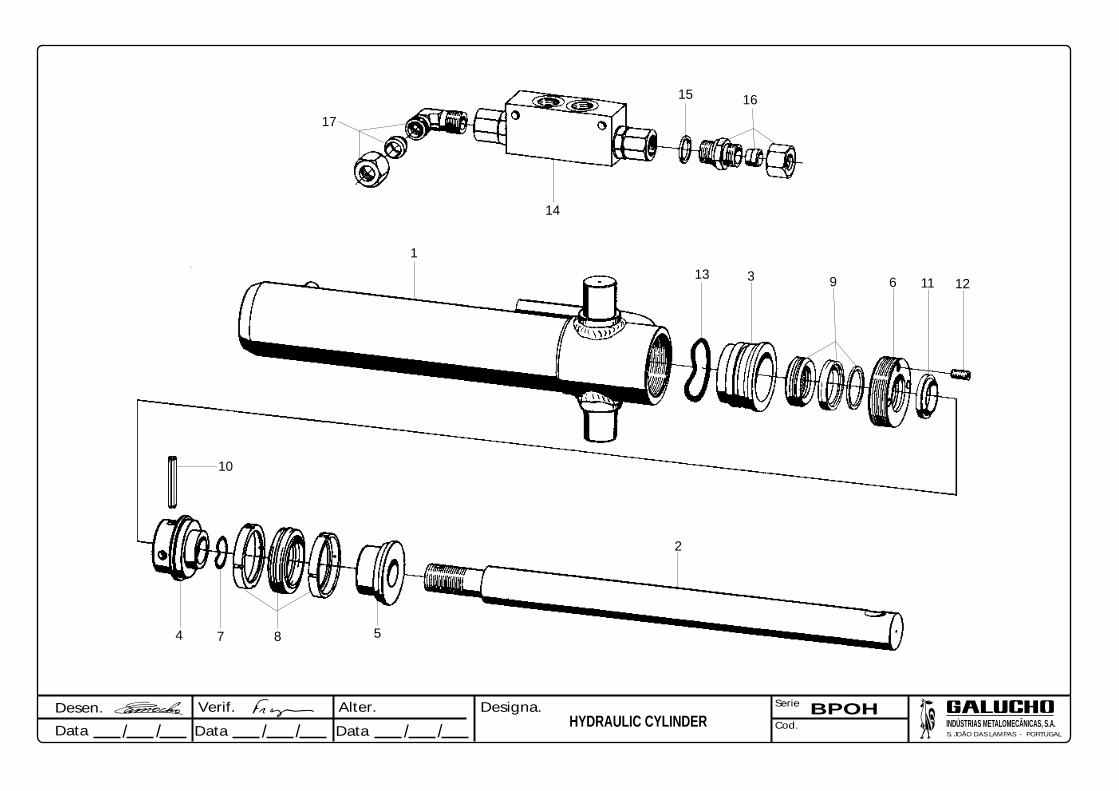
Desen.
Data / / // / /Data Data
Verif. Alter. Designa. Serie
Cod.
BPOHHYDRAULIC CYLINDER
17
15 16
14
13 3 9 6 11 12
1
2
10
4 7 8 5

NOTES

NOTES

NOTES


AV. CENTRAL, N.º 42705-737 S. JOÃO DAS LAMPAS- SINTRA - PORTUGAL
TELEF.:(351) 21 960 85 00 FAX: (351) 21 960 85 99
INDÚSTRIAS METALOMECÂNICAS, S. A.(Fundada por JOSÉ FRANCISCO JUSTINO) -
0608.BP/BPO.3
Top Related