
![07.08. si..[1]](https://static.fdocuments.net/doc/165x107/55b96a00bb61eb7e2f8b4699/0708-si1.jpg)


Languages
Pages
Legal

BA369P/00/en/07.08
71062450
Operating Instructions
Deltatop DP61D, DP62D, DP63DPitot tubes for differential pressure flow measurement
– +
r


Deltatop DP61D, DP62D, DP63D Table of contents
Table of contents
1 Safety instructions . . . . . . . . . . . . . . . . 4
1.1 Designated use . . . . . . . . . . . . . . . . . . . . . . . . . . . . 4
1.2 Installation, commissioning, operation . . . . . . . . . . . 4
1.3 Hazardous area . . . . . . . . . . . . . . . . . . . . . . . . . . . . 4
1.4 Notes on safety conventions and symbols . . . . . . . . . 5
2 Identification . . . . . . . . . . . . . . . . . . . . 6
2.1 Nameplate . . . . . . . . . . . . . . . . . . . . . . . . . . . . . . . 6
2.2 Product structure . . . . . . . . . . . . . . . . . . . . . . . . . . 6
2.3 Documentation . . . . . . . . . . . . . . . . . . . . . . . . . . . . 7
2.4 Certificates and approvals . . . . . . . . . . . . . . . . . . . . 9
2.5 Registered trademarks . . . . . . . . . . . . . . . . . . . . . . . 9
3 Installation . . . . . . . . . . . . . . . . . . . . . 10
3.1 Incoming acceptance, transport, storage . . . . . . . . . 10
3.2 Dimensions . . . . . . . . . . . . . . . . . . . . . . . . . . . . . . 10
3.3 Mounting position for liquid applications . . . . . . . . 11
3.4 Mounting position for gas applications . . . . . . . . . . 12
3.5 Mounting position for steam applications . . . . . . . . 13
3.6 General mounting conditions . . . . . . . . . . . . . . . . . 15
3.7 General mounting hints . . . . . . . . . . . . . . . . . . . . . 19
3.8 Installation steps for the cutting ring version . . . . . 20
3.9 Installation steps for the flange version . . . . . . . . . . 22
3.10 Installation steps for the Flowtap version with safety
chain . . . . . . . . . . . . . . . . . . . . . . . . . . . . . . . . . . . 24
3.11 Installation steps for the Flowtap version with spindle
27
3.12 Installation steps for a Flowtap version with flange . 30
3.13 Installation check . . . . . . . . . . . . . . . . . . . . . . . . . 34
4 Wiring . . . . . . . . . . . . . . . . . . . . . . . . 35
4.1 Wiring of the Deltabar S differential pressure transmitter
35
4.2 Wiring of the integrated Pt100 temperature sensor 36
5 Operation and commissioning . . . . . . 38
5.1 Configuration of the Deltabar S differential pressure
transmitter . . . . . . . . . . . . . . . . . . . . . . . . . . . . . . 38
5.2 Configuration of a temperature and pressure
compensation . . . . . . . . . . . . . . . . . . . . . . . . . . . . 38
5.3 Usage of the accessories . . . . . . . . . . . . . . . . . . . . . 40
6 Troubleshooting . . . . . . . . . . . . . . . . . 44
6.1 Error messages of the Deltabar S . . . . . . . . . . . . . . 44
6.2 Application errors . . . . . . . . . . . . . . . . . . . . . . . . . 45
7 Maintenance and repairs . . . . . . . . . . 46
7.1 Maintenance . . . . . . . . . . . . . . . . . . . . . . . . . . . . . 46
7.2 Exterior cleaning . . . . . . . . . . . . . . . . . . . . . . . . . . 46
7.3 Replacing seals . . . . . . . . . . . . . . . . . . . . . . . . . . . 46
7.4 Spare parts . . . . . . . . . . . . . . . . . . . . . . . . . . . . . . 47
7.5 Return . . . . . . . . . . . . . . . . . . . . . . . . . . . . . . . . . . 48
Endress+Hauser
7.6 Disposal . . . . . . . . . . . . . . . . . . . . . . . . . . . . . . . . . 48
7.7 Contact addresses of Endress+Hauser . . . . . . . . . . . 48
8 Accessories . . . . . . . . . . . . . . . . . . . . . 49
8.1 Overview . . . . . . . . . . . . . . . . . . . . . . . . . . . . . . . 49
8.2 Purge unit DA62P . . . . . . . . . . . . . . . . . . . . . . . . . 50
8.3 Oval flange adapter PZO . . . . . . . . . . . . . . . . . . . . 53
9 Appendix. . . . . . . . . . . . . . . . . . . . . . . 54
9.1 Measuring principle . . . . . . . . . . . . . . . . . . . . . . . . 54
9.2 Flow calculation . . . . . . . . . . . . . . . . . . . . . . . . . . 55
Index . . . . . . . . . . . . . . . . . . . . . . . . . . . . . . 57
3

Safety instructions Deltatop DP61D, DP62D, DP63D
1 Safety instructions
1.1 Designated use
The measuring system is used to measure the volume or mass flow of saturated steam, over-heated
steam, gases and liquids.
Resulting from incorrect or from use other than that desiganted the operational safety of the
measuring devices can be suspended. The manufacturer accepts no liability for damages being
produced from this.
1.2 Installation, commissioning, operation
The Deltatop measuring system is fail-safe and is constructed to the state-of-the-art. It meets the
appropriate standards and EC directives. However, if you use it improperly or other than for its
designated use, it may pose application-specific hazards, e.g. product overflow due to incorrect
installation or configuration. Installation, electrical connection, start-up, operation and maintenance
of the measuring device must therefore be carried out exclusively by trained specialists authorised
by the system operator. Technical personnel must have read and understood these operating
instructions and must adhere to them. You may only undertake modifications or repair work to the
device when it is expressly permitted by the operating instructions.
1.3 Hazardous area
Measuring systems for use in hazardous environments are accompanied by separate "Ex
documentation", which is an integral part of this Operating Manual. Strict compliance with the
installation instructions and ratings as stated in this supplementary documentation is mandatory.
• Ensure that all personnel are suitably qualified.
• Observe the specifications in the certificate as well as national and local standards and regulations.
4 Endress+Hauser

Deltatop DP61D, DP62D, DP63D Safety instructions
1.4 Notes on safety conventions and symbols
In order to highlight safety-relevant or alternative operating procedures in the manual, the following
conventions have been used, each indicated by a corresponding symbol in the margin.
Safety conventions
#Warning!
A warning highlights actions or procedures which, if not performed correctly, will lead to personal
injury, a safety hazard or destruction of the instrument
"Caution!
Caution highlights actions or procedures which, if not performed correctly, may lead to personal
injury or incorrect functioning of the instrument
!Note!
A note highlights actions or procedures which, if not performed correctly, may indirectly affect
operation or may lead to an instrument response which is not planned
Explosion protection
0Device certified for use in explosion hazardous area
If the device has this symbol embossed on its name plate it can be installed in an explosion hazardous
area
-Explosion hazardous area
Symbol used in drawings to indicate explosion hazardous areas. Devices located in and wiring
entering areas with the designation “explosion hazardous areas” must conform with the stated type
of protection.
.Safe area (non-explosion hazardous area)
Symbol used in drawings to indicate, if necessary, non-explosion hazardous areas. Devices located in
safe areas still require a certificate if their outputs run into explosion hazardous areas
Electrical symbols
% Direct voltage
A terminal to which or from which a direct current or voltage may be applied or supplied
&Alternating voltage
A terminal to which or from which an alternating (sine-wave) current or voltage may be applied or
supplied
)Grounded terminal
A grounded terminal, which as far as the operator is concerned, is already grounded by means of an
earth grounding system
*Protective grounding (earth) terminal
A terminal which must be connected to earth ground prior to making any other connection to the
equipment
+Equipotential connection (earth bonding)
A connection made to the plant grounding system which may be of type e.g. neutral star or
equipotential line according to national or company practice
Temperature resistance of the connection cables
States, that the connection cables must be resistant to a temperature of at least 85 °C.t >85°C
Endress+Hauser 5
Identification Deltatop DP61D, DP62D, DP63D
2 Identification
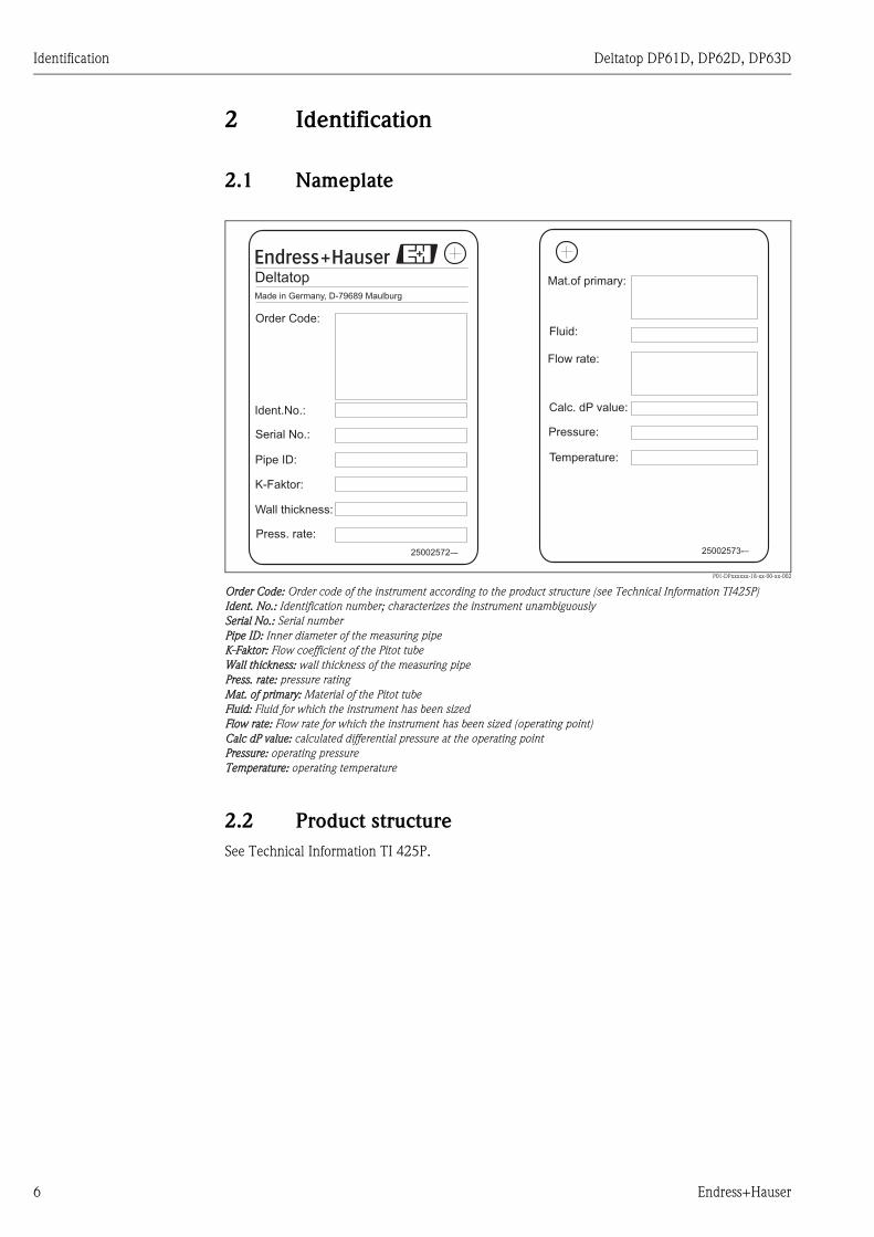
2.1 Nameplate
P01-DPxxxxxx-18-xx-00-xx-002
Order Code: Order code of the instrument according to the product structure (see Technical Information TI425P)
Ident. No.: Identification number; characterizes the instrument unambiguously
Serial No.: Serial number
Pipe ID: Inner diameter of the measuring pipe
K-Faktor: Flow coefficient of the Pitot tube
Wall thickness: wall thickness of the measuring pipe
Press. rate: pressure rating
Mat. of primary: Material of the Pitot tube
Fluid: Fluid for which the instrument has been sized
Flow rate: Flow rate for which the instrument has been sized (operating point)
Calc dP value: calculated differential pressure at the operating point
Pressure: operating pressure
Temperature: operating temperature
2.2 Product structure
See Technical Information TI 425P.
K-Faktor:
25002572-–
Order Code:
DeltatopMade in Germany, D-79689 Maulburg
Ident.No.:
Serial No.:
Pipe ID:
Press. rate:
Mat.of primary:
25002573-–
Fluid:
Flow rate:
Calc. dP value:
Pressure:
Temperature:
Wall thickness:
6 Endress+Hauser
Deltatop DP61D, DP62D, DP63D Identification
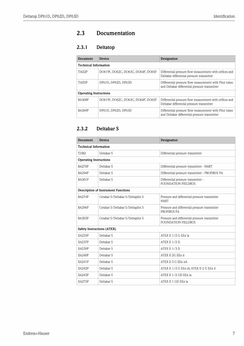
2.3 Documentation
2.3.1 Deltatop
2.3.2 Deltabar S
Document Device Designation
Technical Information
TI422P DO61W, DO62C, DO63C, DO64P, DO65F Differential pressure flow measurement with orifices and
Deltabar differential pressure transmitter
TI425P DP61D, DP62D, DP63D Differential pressure flow measurement with Pitot tubes
and Deltabar differential pressure transmitter
Operating Instructions
BA368P DO61W, DO62C, DO63C, DO64P, DO65F Differential pressure flow measurement with orifices and
Deltabar differential pressure transmitter
BA369P DP61D, DP62D, DP63D Differential pressure flow measurement with Pitot tubes
and Deltabar differential pressure transmitter
Document Device Designation
Technical Information
TI382 Deltabar S Differential pressure transmitter
Operating Instructions
BA270P Deltabar S Differential pressure transmitter - HART
BA294P Deltabar S Differential pressure transmitter - PROFIBUS PA
BA301P Deltabar S Differential pressure transmitter -
FOUNDATION FIELDBUS
Description of Instrument Functions
BA274P Cerabar S/Deltabar S/Deltapilot S Pressure and differential pressure transmitter
HART
BA296P Cerabar S/Deltabar S/Deltapilot S Pressure and differential pressure transmitter
PROFIBUS PA
BA303P Cerabar S/Deltabar S/Deltapilot S Pressure and differential pressure transmitter
FOUNDATION FIELDBUS
Safety Instructions (ATEX)
XA235P Deltabar S ATEX II 1/2 G EEx ia
XA237P Deltabar S ATEX II 1/2 D
XA239P Deltabar S ATEX II 1/3 D
XA240P Deltabar S ATEX II 2G EEx d
XA241P Deltabar S ATEX II 3 G EEx nA
XA242P Deltabar S ATEX II 1/2 G EEx id; ATEX II 2 G EEx d
XA243P Deltabar S ATEX II 1/2 GD EEx ia
XA275P Deltabar S ATEX II 1 GD EEx ia
Endress+Hauser 7

Identification Deltatop DP61D, DP62D, DP63D
2.3.3 Omnigrad T (RTD resistance thermometer)
iTEMP (temperature head transmitter)
2.3.4 Flow and Energy Manager RMS621/RMC621
Document Device Designation
Technical Information
TI269T Omnigrad T TR24 RTD resistance thermometer
TI070R iTEMP TMT181 temperature head transmitter 4...20 mA
TI078R iTEMP TMT182 temperature head transmitter HART
TI079R iTEMP TMT184 temperature head transmitter PROFIBUS PA
Operating Instructions
KA141R iTEMP TMT181 temperature head transmitter 4...20 mA
KA142R iTEMP TMT182 temperature head transmitter HART
BA115R iTEMP TMT184 temperature head transmitter PROFIBUS PA
Safety Instructions (ATEX)
XA003T Omnigrad T TR24 ATEX II 1 GD EEx ia IIC
XA004R iTMEP TMT181 (4...20 mA) ATEX II 1 G EEx ia IIC
XA006R iTEMP TMT182 (HART) ATEX II 1 G EEx ia IIC
XA008R iTEMP TMT184 (PROFIBUS PA) ATEX II 1 G EEx ia IIC
Document Device
Technical Information
TI092R Energy Manager RMS621
TI098R Flow and Energy Manager RMC621
Operating Instructions
BA127R Energy Manager RMS621
BA144R Flow and Energy Manager RMC621
8 Endress+Hauser

Deltatop DP61D, DP62D, DP63D Identification
2.4 Certificates and approvals
2.4.1 CE mark, declaration of conformity
The device is designed to meet state-of-the-art safety requirements, has been tested and left the
factory in a condition in which it is safe to operate. The device complies with the applicable
standards and regulations as listed in the EC declaration of conformity and thus complies with the
statutory requirements of the EC directives. Endress+Hauser confirms the successful testing of the
device by affixing to it the CE mark.
2.4.2 European Pressure Equipment Directive 97/23/EC (PED)
Deltatop Pitot tubes comply with article 3.3 of the Pressure Equipment Directive 97/23/EC and
thus have no CE mark affixed to them.
2.5 Registered trademarks
HART®
Registered trademark of HART Communication Foundation, Austin, USA
PROFIBUS®
Registered trademark of the PROFIBUS Trade Organisation, Karlsruhe, Germany
FOUNDATION Fieldbus®
Registered trademark of the Fieldbus Foundation Austin, Texas, USA
VITON®
Registered trademark of the company, E.I. Du Pont de Nemours & Co., Wilmington, USA
Ermeto®
Registered trademark of the Parker Hannifin GmbH, Bielefeld, Germany
Endress+Hauser 9
Installation Deltatop DP61D, DP62D, DP63D
3 Installation
3.1 Incoming acceptance, transport, storage
3.1.1 Incoming acceptance
Check the packing and contents for any sign of damage.
Check the shipment, make sure nothing is missing and that the scope of supply matches your order.
3.1.2 Transport
" Caution!
Follow the safety instructions and transport conditions for instruments of more than 18 kg.
Do not lift the measuring instrument by the housing of the transmitter in order to transport it.
3.1.3 Storage
For storing and transport, shock proof packaging of the measuring instrument is required. The
original packaging material provides optimum protection.
The permissible storage temperature for the Deltabar transmitter is -40 °C ... +80 °C.
3.2 Dimensions
See Technical Information TI425P.
10 Endress+Hauser

Deltatop DP61D, DP62D, DP63D Installation
3.3 Mounting position for liquid applications
With liquid applications, the transmitter must be mounted below the pipe. All impulse pipes must
be installed with a slope of at least 1:15 to the transmitter - coming from the process connection.
This ensures that trapped air travels back to the process pipe and thus does not influence the
measurement.
! Note!
When measuring in fluids with solid contents, such as dirty liquids, installing separators (5) and
drain valves (6) is useful for capturing and removing sediment.
P01-DPxxxxxx-11-xx-xx-xx-005
A: Preferred configuration; B: alternative configuration (requires less space; only possible for clean media)
1: Pitot tube; 2: Shut-off valves; 3: Three-valve manifold; 4: Differential pressure transmitter Deltabar; 5: Separator; 6: Drain
valves
" Caution!
For flow measurements in vertical pipes, the primary device should be mounted at a position with
upward flow. This prevents partial filling of the pipe during the measurement.
+ –
1
2
3
4
5
6
2
5
+ –
1
2
3
5
6
2
4
5
A B
6
6
compact; vertical compact; horizontal remote; vertical remote; horizontal
flow upwards
DP6xD-EV...
P01-DP61Dxxx-11-00-00-xx-001
mounting left
DP6xD-EB...
P01-DP61Dxxx-11-00-00-xx-009
upward/downward
DP6xD-DW...
P01-DP61Dxxx-11-00-00-xx-014
top/bottom
DP6xD-DD...
P01-DP61Dxxx-11-00-00-xx-017
flow downwards
DP6xD-EU...
P01-DP61Dxxx-11-00-00-xx-002
mounting right
DP6xD-EC...
P01-DP61Dxxx-11-00-00-xx-010
Endress+Hauser 11

Installation Deltatop DP61D, DP62D, DP63D
3.4 Mounting position for gas applications
With gas applications, the transmitter must be mounted above the pipe. All impulse pipes must be
installed with a slope of at least 1:15 to the process connection - coming from the transmitter. This
ensures that any condensate flows back into the process pipe and thus does not influence the
measurement.
! Note!
When measuring in humid gases, installation of condensate separators (5) and drain valves (6) is
useful for capturing and removing condensate.
P01-DPxxxxxx-11-xx-xx-xx-006
A: Preferred configuration; B: Alternative configuration (if the transmitter can not be mounted above the pipe)
1: Pitot tube; 2: Shut-off valves ; 3: Three-valve manifold; 4: Differential pressure transmitter Deltabar; 5: Separator;
6: Drain valve
+ –
1
2
3
4
A
1
3
2
B
4
+ –5
6
5
6
2
compact; vertical compact; horizontal remote; vertical remote; horizontal
flow upwards
DP6xD-CV...
P01-DP61Dxxx-11-00-00-xx-001
mounting left
DP6xD-CB...
P01-DP61Dxxx-11-00-00-xx-007
upward/downward
DP6xD-BW...
P01-DP61Dxxx-11-00-00-xx-013
top/bottom
DP6xD-BD...
P01-DP61Dxxx-11-00-00-xx-016
flow downwards
DP6xD-CU...
P01-DP61Dxxx-11-00-00-xx-002
mounting right
DP6xD-CC...
P01-DP61Dxxx-11-00-00-xx-008
12 Endress+Hauser
Deltatop DP61D, DP62D, DP63D Installation
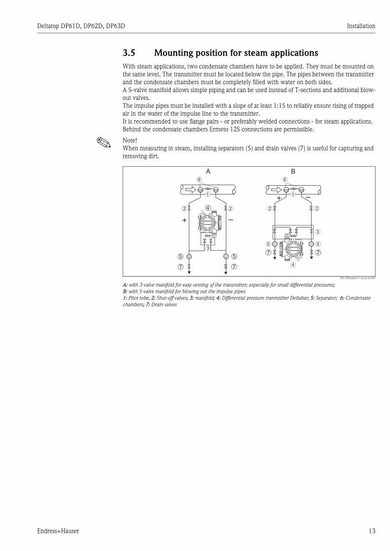
3.5 Mounting position for steam applications
With steam applications, two condensate chambers have to be applied. They must be mounted on
the same level. The transmitter must be located below the pipe. The pipes between the transmitter
and the condensate chambers must be completely filled with water on both sides.
A 5-valve manifold allows simple piping and can be used instead of T-sections and additional blow-
out valves.
The impulse pipes must be installed with a slope of at least 1:15 to reliably ensure rising of trapped
air in the water of the impulse line to the transmitter.
It is recommended to use flange pairs - or preferably welded connections - for steam applications.
Behind the condensate chambers Ermeto 12S connections are permissible.
! Note!
When measuring in steam, installing separators (5) and drain valves (7) is useful for capturing and
removing dirt.
P01-DPxxxxxx-11-xx-xx-xx-007
A: with 3-valve manifold for easy venting of the transmitter; especially for small differential pressures;
B: with 5-valve manifold for blowing out the impulse pipes
1: Pitot tube; 2: Shut-off valves; 3: manifold; 4: Differential pressure tranmsitter Deltabar; 5: Separator; 6: Condensate
chambers; 7: Drain valves
+ –
4
3
5
6
5
2
1
2➃
+ –
➄
➆
➄
6
1
2 2
3
➆
A B
➆ ➆
Endress+Hauser 13

Installation Deltatop DP61D, DP62D, DP63D
compact; vertical compact; horizontal remote; vertical remote; horizontal
flow upwards
DP6xD-GV...
P01-DP61Dxxx-11-00-00-xx-005
mounting left
DP6xD-GB...
P01-DP61Dxxx-11-00-00-xx-011
flow upwards
DP6xD-FV...
P01-DP61Dxxx-11-00-00-xx-015
mounting left
DP6xD-FB...
P01-DP61Dxxx-11-00-00-xx-018
flow downwards
DP6xD-GU...
P01-DP61Dxxx-11-00-00-xx-006
mounting right
DP6xD-GC...
P01-DP61Dxxx-11-00-00-xx-012
flow upwards
DP6xD-FU...
P01-DP61Dxxx-11-00-00-xx-020
mounting right
DP6xD-FC...
P01-DP61Dxxx-11-00-00-xx-019
14 Endress+Hauser

Deltatop DP61D, DP62D, DP63D Installation
3.6 General mounting conditions
3.6.1 Up- and downstream lengths
In order to ensure a homogeneous flow profile it is necessary to mount the orifice in a sufficient
distance to narrowings or bends of the pipe. The required upstream and downstream lengths for
different types of obstacles are summarized in the following table:
Examples (schematic)
P01-DPxxxxxx-11-xx-xx-xx-008
1: upstream length; 2: downstream length;
a: 90° bend; b: valve, open; c: 2x90° bend
! Note!
The requirments concerning the pipe according to ISO5167 should be met (weld seams, roughness
etc).
3.6.2 Homogeneity
The fluid must be homogeneous. Changes of the state of aggregation (liquid, gas, steam) are not
permissible.
The measuring pipe must be completely filled.
Type of obstacle Min. upstream length Min. downstream length
90° bend 7 x D 3 x D
2x90° bend
in the same plane
9 x D 3 x D
2x90° bend
in perpendicular planes
17 x D 4 x D
concentric reducer 7 x D 3 x D
concentric expander 7 x D 3 x D
ball/gate valve, fully open 24 x D 4 x D
D: Inner pipe diameter
1 2
a
b
c
Endress+Hauser 15
Installation Deltatop DP61D, DP62D, DP63D
3.6.3 Mounting position
• The mounting position must be chosen such that access to the transmitter is always possible.
• If the following process temperatures are exceeded, a remote version has to be used. The
transmitter must be mounted in a sufficient distance from the primary device.
3.6.4 Heat insulation
Some applications require suitable measures to avoid heat loss to the ambiance. A wide range of
materials can be used to provide the required insulation.
With the comapct version, the thickness of the insulating layer is taken into account in the sizing.
The actual thickness must not be larger than the thickness specified in the Sizing sheet - Data sheet.
With insulated pipes make sure that the impulse pipes are not covered in order to ensure sufficient
heat dissipation. Otherwise the transmitter may become overheated (or undercooled). This applies
equally to both the compact and the remote version.
" Caution!
Danger of electronics overheating!
Make sure that the impulse pipes between the primary element and the transmitter are always kept
free of insulation.
Application Maximum temperature for the compact version
Gas / Liquids 200 °C (392 °F)
Steam 300 °C (572 °F)
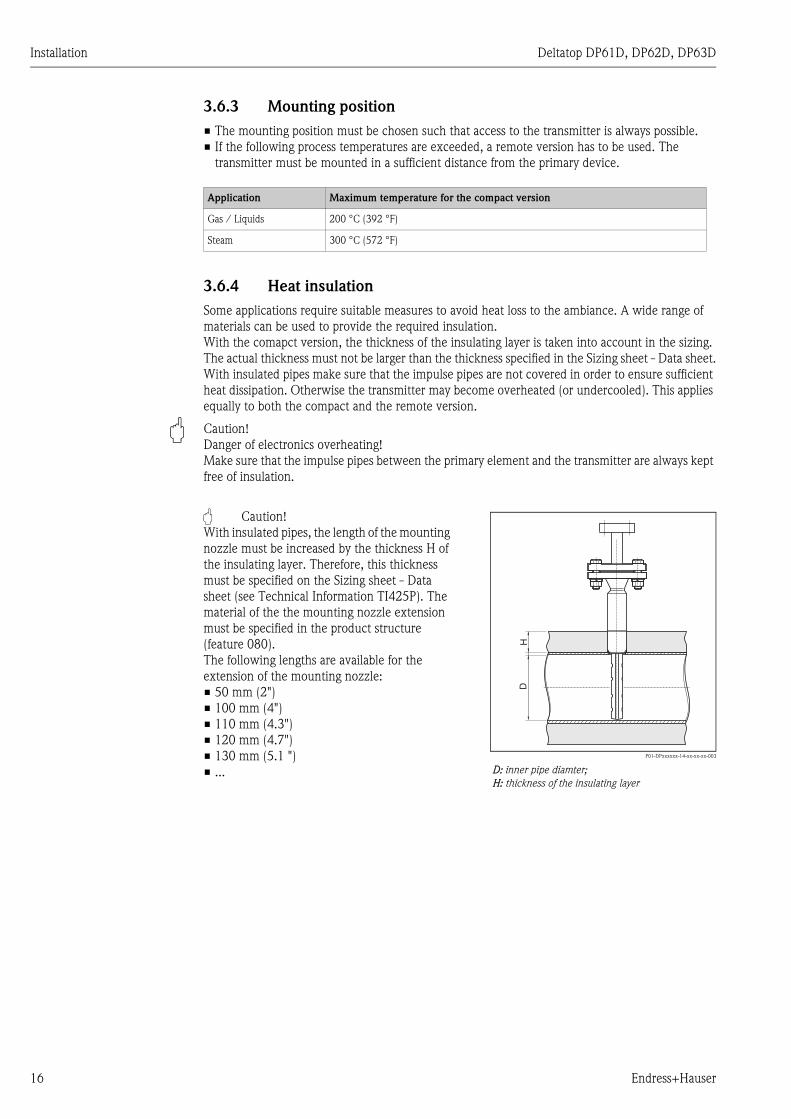
" Caution!
With insulated pipes, the length of the mounting
nozzle must be increased by the thickness H of
the insulating layer. Therefore, this thickness
must be specified on the Sizing sheet - Data
sheet (see Technical Information TI425P). The
material of the the mounting nozzle extension
must be specified in the product structure
(feature 080).
The following lengths are available for the
extension of the mounting nozzle:
• 50 mm (2")
• 100 mm (4")
• 110 mm (4.3")
• 120 mm (4.7")
• 130 mm (5.1 ")
• ...
P01-DPxxxxxx-14-xx-xx-xx-003
D: inner pipe diamter;
H: thickness of the insulating layer
HD
16 Endress+Hauser
Deltatop DP61D, DP62D, DP63D Installation
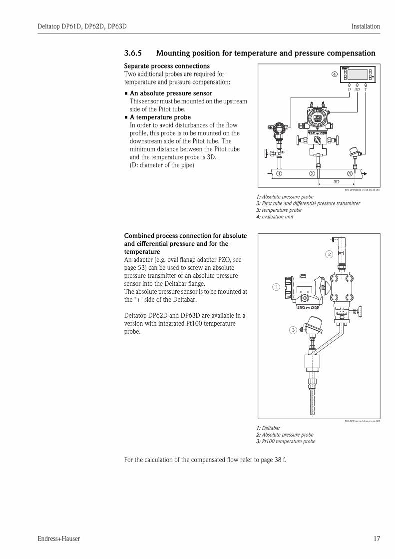
3.6.5 Mounting position for temperature and pressure compensation
For the calculation of the compensated flow refer to page 38 f.
Separate process connections
Two additional probes are required for
temperature and pressure compensation:
• An absolute pressure sensor
This sensor must be mounted on the upstream
side of the Pitot tube.
• A temperature probe
In order to avoid disturbances of the flow
profile, this probe is to be mounted on the
downstream side of the Pitot tube. The
minimum distance between the Pitot tube
and the temperature probe is 3D.
(D: diameter of the pipe)
P01-DPPxxxxx-15-xx-xx-xx-007
1: Absolute pressure probe
2: Pitot tube and differential pressure transmitter
3: temperature probe
4: evaluation unit
1 2 3
4
RMC621RMC621
Endress+HauserEndress+Hauser
�p Tp
3D
Combined process connection for absolute
and cifferential pressure and for the
temperature
An adapter (e.g. oval flange adapter PZO, see
page 53) can be used to screw an absolute
pressure transmitter or an absolute pressure
sensor into the Deltabar flange.
The absolute pressure sensor is to be mounted at
the "+" side of the Deltabar.
Deltatop DP62D and DP63D are available in a
version with integrated Pt100 temperature
probe.
P01-DPPxxxxx-14-xx-xx-xx-002
1: Deltabar
2: Absolute pressure probe
3: Pt100 temperature probe
ENDRESS+HAUSERCERABAR T
1
2
3
Endress+Hauser 17

Installation Deltatop DP61D, DP62D, DP63D
3.6.6 Measuring range
The lower limit of the measuring range is determined by the minimum Reynolds number required
for the measurement. For details see Technical Information TI25P.
The upper limit of the measuring range is determined by the mechanical load.
Both limits can be calculated by the "Applicator" selection and sizing tool.
3.6.7 Alignment of the Pitot tube
The alignment of the Pitot tube must be within the following limits:
P01-DPxxxxxx-11-xx-xx-xx-018
A: axial alignment;
B: radial alignment;
C: alignment in the flow direction (for horizontal pipes)
D: alignment in the flow direction (for vertical pipes)
+/- 5° +/- 3°
+/- 3°
+/- 3°
A B
C
D
18 Endress+Hauser

Deltatop DP61D, DP62D, DP63D Installation
3.7 General mounting hints
• The primary element is calculated for specific pipe and operating data. Therefore it is essential to
check if the data on the nameplate (see page 6) match the actual operating data.
• Before installing the device, check if the required upstream and downstream lengths are provided
(see page 15).
• Observe the required mounting position:
– for liquids: page 11
– for gases: page 12
– for steam: page 13
• For remote versions:
The shut-off valves are mounted to the pressure taps of the primary element or (in the case of
steam applications) to the condensate chambers.
• For remote versions:
The impulse pipes have to be installed with a slope of at least 1:15.
– For steam and liquids, a venting possibility has to be provided at the highest point.
– For gases, a drainage has to be provided at the lowest point.
The impulse lines (+) and (-) have to be mounted to the respective inlets (process connection) of
the manifold. The transmitter is directly screwed to the manifold with the supplied screws and
gaskets.
Endress+Hauser 19

Installation Deltatop DP61D, DP62D, DP63D
3.8 Installation steps for the cutting ring version
P01-DP6xxxx-17-xx-xx-xx-001
A: without end support; B: with end support
1: welding socket; 2: cutting ring; 3: union nut; 4: probe; 5: end support
D1: diameter of the hole (depending on the probe, see below)
! Note!
Before installing the Pitot tube, perform the following checks:
• Do the pipe dimensions (inner diameter, wall thickness, thickness of insulation) match the data
of the order and the specifications of the instrument?
• Do the medium properties and process data match the specifications on the supplied calculation
sheet?
1. Drill a hole with the diameter D1 into the pipe.
2. Remove the cutting ring (2) from the welding socket (1) in order to protect it from thermal
stress which is generated by the welding process. The union nut (3) must remain on the
welding socket in order to to protect the thread from being damaged.
3. Tack the welding socket (1) onto the pipe leaving a gap of approx. 2mm. Align the welding
socket exactly at right-angle to the pipe axis (e.g. using a stud).
4. If an end support is to be mounted:
a. Take a cord and tie one of its ends around the welding socket (1). Wrap the other end of
the cord around the pipe so that it forms a loop around the pipe. Mark the half-way point
of the circumference on the pipe.
b. Drill a second hole with the diameter D1 into the pipe.
c. Tack the end support (5) onto the pipe leaving a gap of approx. 2 mm.
d. Insert the probe (4) into the pipe and check the alignment of the end support (5). If
necessary, adjust the alignment.
5. Perform the final welding.
6. Remove the union nut (3) from the welding socket (1) and slip it over the probe (4).
7. Slip the cutting ring (2) over the probe (4). The shorter cone of the cutting ring mus point in
the direction of the probe head.
D1
D1
1
2
3
4
1
2
3
5
4
D1
A B
Probe Diamter of the hole (D1)
DP61D 18 mm ( 0.71")
DP62D 35 mm (1.4")
DP63D 47 mm (1.9")
20 Endress+Hauser

Deltatop DP61D, DP62D, DP63D Installation
8. Insert the probe (4) together with the union nut (3) and the cutting ring (2) into the welding
socket until the probe tip touches the opposite pipe wall or the end support, respectively.
9. Check if the cutting ring (2) is properly seated and slightly tighten the union nut (3).
10. Align the probe so that the arrow on the probe points exactly in the direction of the flow. (The
upstream side is marked"+", the downstream side is marked "-".) Tighten the union nut (3).
11. Check the sensor alignment again. If the sensor is not aligned correctly, loosen the union nut
(3) and repeat the last installation step.
12. Installation of the shut-off valves (for the remote version):
The shut-off valves have to be mounted to the nozzles of the primary element or (in the case
of steam applications) to the condensate chambers.
! Note!
With welding connections the shut-off valves are already mounted on delivery.
13. Installation of the manifold and the transmitter (for the remote version):
The impulse pipes have to be installed with the required slope
(for liquids: → ä 11, for gases: → ä 12, for steam: → ä 13).
– For steam and liquids, a venting possibility has to be provided at the highest point.
– For gases, a drainage has to be provided at the lowest point.
The impulse lines (+) and (-) have to be mounted to the respective inlets (process connections)
of the manifold. The transmitter is directly screwed to the manifold with the supplied screws
and gaskets.
Endress+Hauser 21
Installation Deltatop DP61D, DP62D, DP63D
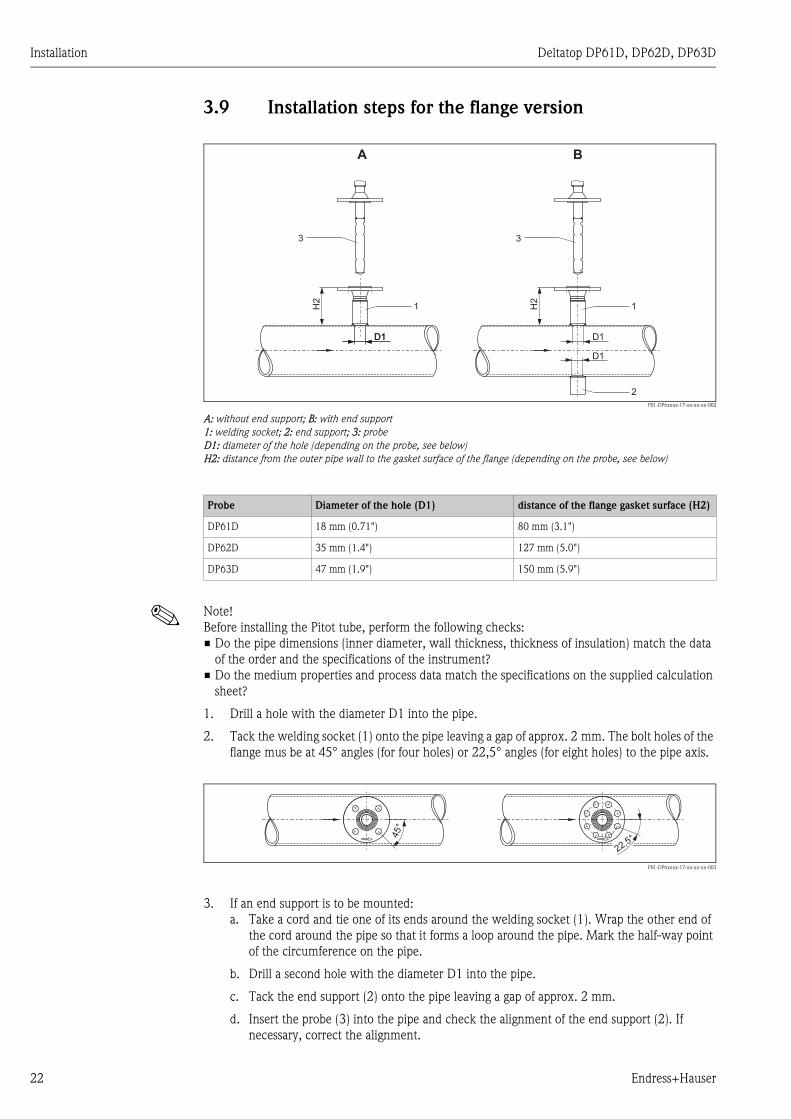
3.9 Installation steps for the flange version
P01-DP6xxxx-17-xx-xx-xx-002
A: without end support; B: with end support
1: welding socket; 2: end support; 3: probe
D1: diameter of the hole (depending on the probe, see below)
H2: distance from the outer pipe wall to the gasket surface of the flange (depending on the probe, see below)
! Note!
Before installing the Pitot tube, perform the following checks:
• Do the pipe dimensions (inner diameter, wall thickness, thickness of insulation) match the data
of the order and the specifications of the instrument?
• Do the medium properties and process data match the specifications on the supplied calculation
sheet?
1. Drill a hole with the diameter D1 into the pipe.
2. Tack the welding socket (1) onto the pipe leaving a gap of approx. 2 mm. The bolt holes of the
flange mus be at 45° angles (for four holes) or 22,5° angles (for eight holes) to the pipe axis.
P01-DP6xxxx-17-xx-xx-xx-003
3. If an end support is to be mounted:
a. Take a cord and tie one of its ends around the welding socket (1). Wrap the other end of
the cord around the pipe so that it forms a loop around the pipe. Mark the half-way point
of the circumference on the pipe.
b. Drill a second hole with the diameter D1 into the pipe.
c. Tack the end support (2) onto the pipe leaving a gap of approx. 2 mm.
d. Insert the probe (3) into the pipe and check the alignment of the end support (2). If
necessary, correct the alignment.
H2
1 H2
1
2
D1 D1D1
D1
A B
3 3
Probe Diameter of the hole (D1) distance of the flange gasket surface (H2)
DP61D 18 mm (0.71") 80 mm (3.1")
DP62D 35 mm (1.4") 127 mm (5.0")
DP63D 47 mm (1.9") 150 mm (5.9")
45°
22,5°
22 Endress+Hauser
Deltatop DP61D, DP62D, DP63D Installation
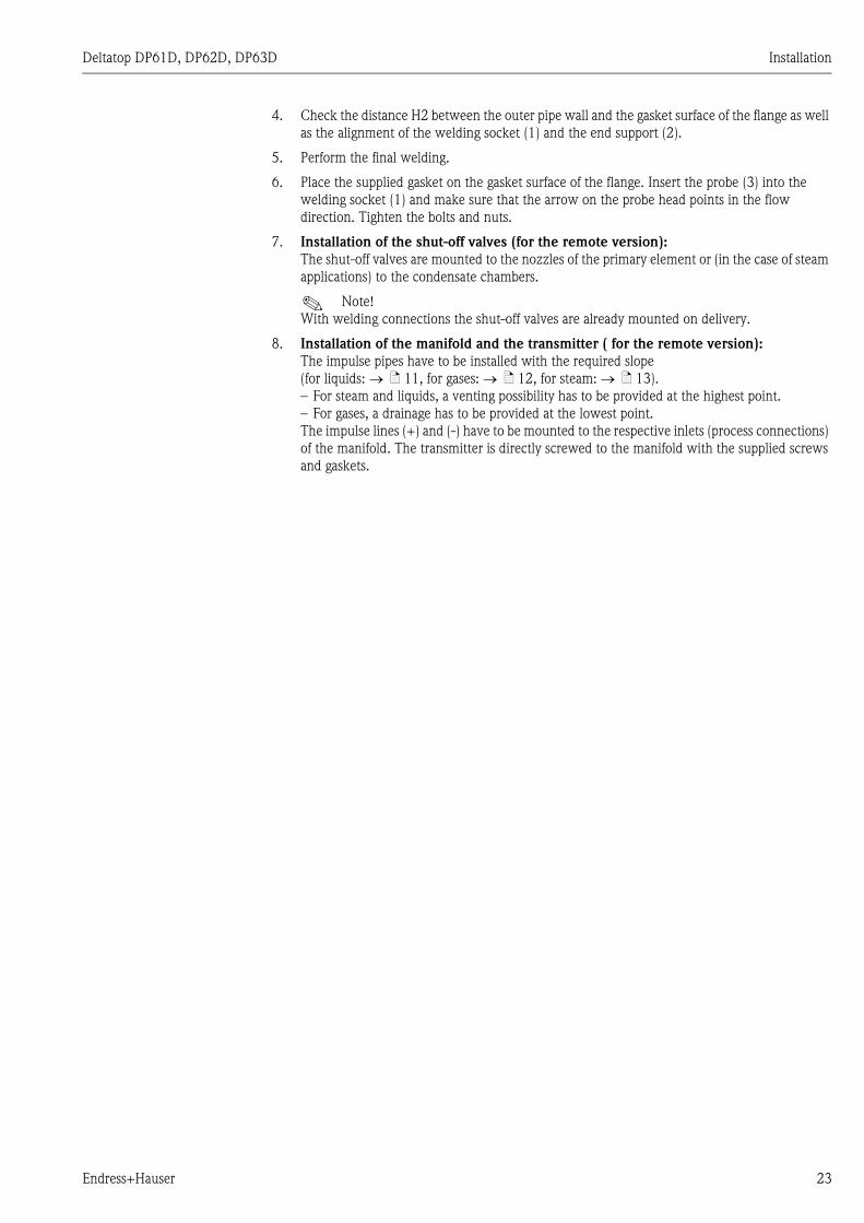
4. Check the distance H2 between the outer pipe wall and the gasket surface of the flange as well
as the alignment of the welding socket (1) and the end support (2).
5. Perform the final welding.
6. Place the supplied gasket on the gasket surface of the flange. Insert the probe (3) into the
welding socket (1) and make sure that the arrow on the probe head points in the flow
direction. Tighten the bolts and nuts.
7. Installation of the shut-off valves (for the remote version):
The shut-off valves are mounted to the nozzles of the primary element or (in the case of steam
applications) to the condensate chambers.
! Note!
With welding connections the shut-off valves are already mounted on delivery.
8. Installation of the manifold and the transmitter ( for the remote version):
The impulse pipes have to be installed with the required slope
(for liquids: → ä 11, for gases: → ä 12, for steam: → ä 13).
– For steam and liquids, a venting possibility has to be provided at the highest point.
– For gases, a drainage has to be provided at the lowest point.
The impulse lines (+) and (-) have to be mounted to the respective inlets (process connections)
of the manifold. The transmitter is directly screwed to the manifold with the supplied screws
and gaskets.
Endress+Hauser 23
Installation Deltatop DP61D, DP62D, DP63D
3.10 Installation steps for the Flowtap version with safety
chain
3.10.1 Mounting
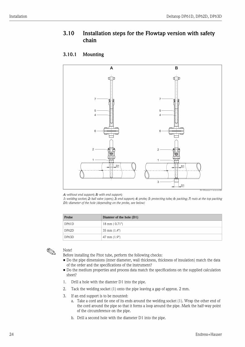
P01-DPxxxxxx-11-xx-xx-xx-009
A: without end support; B: with end support;
1: welding socket; 2: ball valve (open); 3: end support; 4: probe; 5: protecting tube; 6: packing; 7: nuts at the top packing
D1: diameter of the hole (depending on the probe, see below)
! Note!
Before installing the Pitot tube, perform the following checks:
• Do the pipe dimensions (inner diameter, wall thickness, thickness of insulation) match the data
of the order and the specifications of the instrument?
• Do the medium properties and process data match the specifications on the supplied calculation
sheet?
1. Drill a hole with the diamter D1 into the pipe.
2. Tack the welding socket (1) onto the pipe leaving a gap of approx. 2 mm.
3. If an end support is to be mounted:
a. Take a cord and tie one of its ends around the welding socket (1). Wrap the other end of
the cord around the pipe so that it forms a loop around the pipe. Mark the half-way point
of the circumference on the pipe.
b. Drill a second hole with the diameter D1 into the pipe.
D1 D1
D1
1 1
2 2
3
A B
4
5
7
4
5
7
6 6
Probe Diamter of the hole (D1)
DP61D 18 mm ( 0.71")
DP62D 35 mm (1.4")
DP63D 47 mm (1.9")
24 Endress+Hauser

Deltatop DP61D, DP62D, DP63D Installation
c. Tack the end support (3) onto the pipe leaving a gap of approx. 2 mm.
d. Insert the probe (4) into the pipe and check the alignment of the end support (3). If
necessary, correct the alignment.
4. Perform the final welding.
5. Apply a suitable sealing compound to the threaded nozzle of the ball valve (2)and screw it into
the welding scoket (1).
6. Verify that the probe (4) is fully retracted into the protecting tube (5).
7. Apply a suitable sealing compound to the threaded nozzle of the packing (6) and screw it into
the ball valve (2).
8. Open the valve (2).
9. Slightly loosen the packing (7) until the probe (4) can be moved. Insert the probe into the pipe
until the probe tip touches the opposite pipe wall or the wall of the end support, respectively.
10. Tighten the nuts at the top and bottom packing (6/7).
11. Installation of the shut-off valves (for the remote version):
The shut-off valves are mounted to the nozzles of the primary element or (in the case of steam
applications) to the condensate chambers.
! Note!
With welding connections the shut-off valves are already mounted on delivery.
12. Installation of the manifold and the transmitter (for the remote version):
The impulse pipes have to be installed with the required slope
(for liquids: → ä 11, for gases: → ä 12, for steam: → ä 13).
– For steam and liquids, a venting possibility has to be provided at the highest point.
– For gases, a drainage has to be provided at the lowest point.
The impulse lines (+) and (-) have to be mounted to the respective inlets (process connections)
of the manifold. The transmitter is directly screwed to the manifold with the supplied screws
and gaskets.
Endress+Hauser 25

Installation Deltatop DP61D, DP62D, DP63D
3.10.2 Insertion and removal of the probe without process interruption
P01-DPxxxxxx-11-xx-xx-xx-0
1: welding socket; 2: ball valve (closed); 4: probe ; 5: protecting tube; 6: packing with flange; 7: nuts at the top packing
With the Flowtap version, the Pitot tube can be removed (e.g. for cleaning) without the need of an
interruption of the process. To do so, perform the following steps:
1. Close the valves at the probe head. If required, depressurize and disconnect the impulse lines.
2. Slightly loosen the nuts at the packings (6/7) until the probe can be moved without medium
escaping.
3. Retract the probe from the pipe until the safety chain defines the limit stop.
4. Close the ball valve (2).
5. The probe can now be completely disconnected from the pipe:
a. Detach safety chain; withdraw probe
b. if there is not enough space: disconnect at the packing (6).
For insertion of the probe perform these steps in reverse order.
1
2
4
5
7
6
26 Endress+Hauser
Deltatop DP61D, DP62D, DP63D Installation
3.11 Installation steps for the Flowtap version with spindle
3.11.1 Mounting
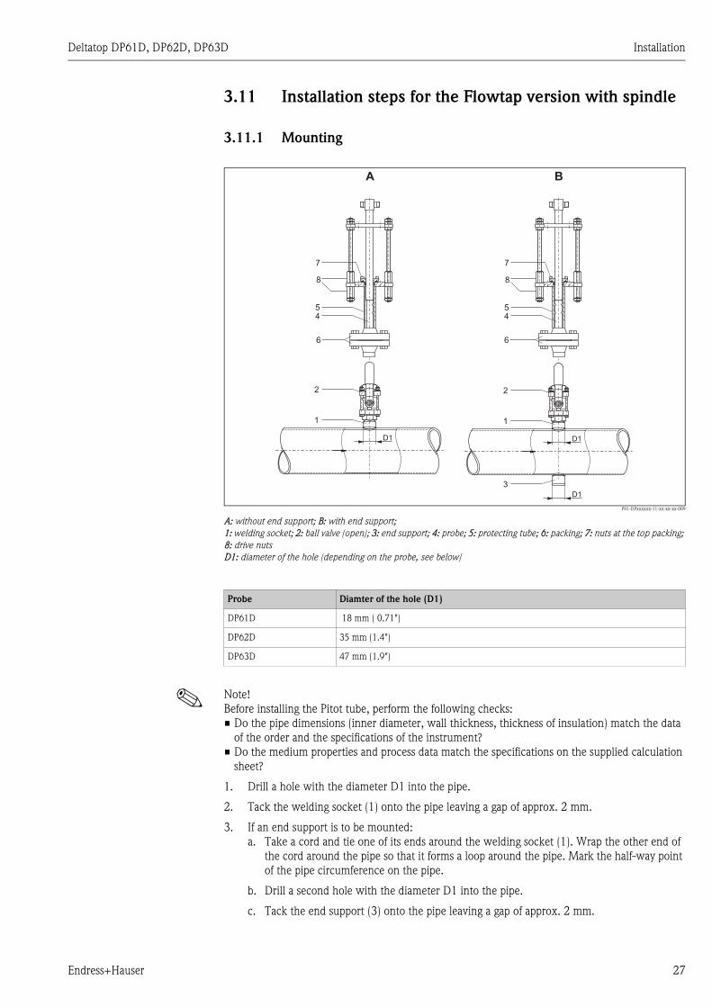
P01-DPxxxxxx-11-xx-xx-xx-009
A: without end support; B: with end support;
1: welding socket; 2: ball valve (open); 3: end support; 4: probe; 5: protecting tube; 6: packing; 7: nuts at the top packing;
8: drive nuts
D1: diameter of the hole (depending on the probe, see below)
! Note!
Before installing the Pitot tube, perform the following checks:
• Do the pipe dimensions (inner diameter, wall thickness, thickness of insulation) match the data
of the order and the specifications of the instrument?
• Do the medium properties and process data match the specifications on the supplied calculation
sheet?
1. Drill a hole with the diameter D1 into the pipe.
2. Tack the welding socket (1) onto the pipe leaving a gap of approx. 2 mm.
3. If an end support is to be mounted:
a. Take a cord and tie one of its ends around the welding socket (1). Wrap the other end of
the cord around the pipe so that it forms a loop around the pipe. Mark the half-way point
of the pipe circumference on the pipe.
b. Drill a second hole with the diameter D1 into the pipe.
c. Tack the end support (3) onto the pipe leaving a gap of approx. 2 mm.
D1 D1
D1
1 1
2 2
3
A B
7
45
8
7
45
8
6 6
Probe Diamter of the hole (D1)
DP61D 18 mm ( 0.71")
DP62D 35 mm (1.4")
DP63D 47 mm (1.9")
Endress+Hauser 27
Installation Deltatop DP61D, DP62D, DP63D
d. Insert the probe (4) into the pipe and check the alignment of the end support (3). If
necessary, correct the alignment.
4. Perform the final welding.
5. Apply a suitable sealing compound to the threaded nozzle of the ball valve (2)and screw it into
the welding scoket (1).
6. Verify that the probe (4) is fully retracted into the protecting tube (5).
7. Apply a suitable sealing compound to the threaded nozzle of the packing (6) and screw it into
the ball valve (2).
8. Open the ball valve (2).
9. Slightly loosen the packing (7) until the probe (4) can be moved.
10. Insert the probe into the pipe by turning the drive nuts (8) clockwise as viewed from the top.
The nuts must be tightened alternately, about two turns at a time, to prevent an undesired tilt
of the probe. Continue this procedure until the probe touches the opposite pipe wall or the
wall of the end support.
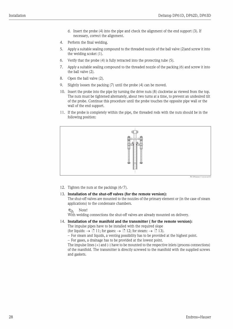
11. If the probe is completely within the pipe, the threaded rods with the nuts should be in the
following position:
P01-DPxxxxxx-11-xx-xx-xx-013
12. Tighten the nuts at the packings (6/7).
13. Installation of the shut-off valves (for the remote version):
The shut-off valves are mounted to the nozzles of the primary element or (in the case of steam
applications) to the condensate chambers.
! Note!
With welding connections the shut-off valves are already mounted on delivery.
14. Installation of the manifold and the transmitter ( for the remote version):
The impulse pipes have to be installed with the required slope
(for liquids: → ä 11; for gases: → ä 12; for steam: → ä 13).
– For steam and liquids, a venting possibility has to be provided at the highest point.
– For gases, a drainage has to be provided at the lowest point.
The impulse lines (+) and (-) have to be mounted to the respective inlets (process connections)
of the manifold. The transmitter is directly screwed to the manifold with the supplied screws
and gaskets.
28 Endress+Hauser

Deltatop DP61D, DP62D, DP63D Installation
3.11.2 Insertion and removal of the probe without process interruption
P01-DPxxxxxx-11-xx-xx-xx-014
1: welding socket; 2: ball valve (closed); 4: probe ; 5: protective tube; 6: packing; 7: nuts at the top packing; 8: drive nuts
With the Flowtap version, the Pitot tube can be removed (e.g. for cleaning) without the need of an
interruption of the process. To do so, perform the following steps:
1. Close the valves at the probe head. If required, depressurize and disconnect the impulse lines.
2. Slightly loosen the nuts at the packings (6/7) until the probe can be moved without medium
escaping.
3. Retract the Flowtap by rotating the drive nuts (8) counter-clockwise as viewed from top. The
nuts must be turned alternately, about two turns a time, to prevent an undesired tilt of the
probe.
4. If the probe is fully retracted (observe the position of the threaded bolts), the ball valve (2) can
be closed and the probe can be completely disconnected (disconnect at the packing (6)).
For insertion of the probe perform these steps in reverse order.
1
2
4
5
7
8
8
6
Endress+Hauser 29
Installation Deltatop DP61D, DP62D, DP63D
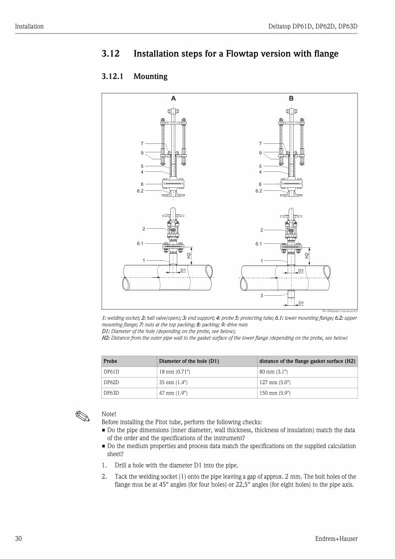
3.12 Installation steps for a Flowtap version with flange
3.12.1 Mounting
P01-DPxxxxxx-11-xx-xx-xx-015
1: welding socket; 2: ball valve(open); 3: end support; 4: probe 5: protecting tube; 6.1: lower mounting flange; 6.2: upper
mounting flange; 7: nuts at the top packing; 8: packing; 9: drive nuts
D1: Diameter of the hole (depending on the probe, see below);
H2: Distance from the outer pipe wall to the gasket surface of the lower flange (depending on the probe, see below)
! Note!
Before installing the Pitot tube, perform the following checks:
• Do the pipe dimensions (inner diameter, wall thickness, thickness of insulation) match the data
of the order and the specifications of the instrument?
• Do the medium properties and process data match the specifications on the supplied calculation
sheet?
1. Drill a hole with the diameter D1 into the pipe.
2. Tack the welding socket (1) onto the pipe leaving a gap of approx. 2 mm. The bolt holes of the
flange mus be at 45° angles (for four holes) or 22,5° angles (for eight holes) to the pipe axis.
D1 D1
1 1
2 2
D1
3
H2
H2
A B
6.2
7
4
5
8
9
6.2
7
4
5
9
6.1 6.1
8
Probe Diameter of the hole (D1) distance of the flange gasket surface (H2)
DP61D 18 mm (0.71") 80 mm (3.1")
DP62D 35 mm (1.4") 127 mm (5.0")
DP63D 47 mm (1.9") 150 mm (5.9")
30 Endress+Hauser

Deltatop DP61D, DP62D, DP63D Installation
P01-DP6xxxx-17-xx-xx-xx-003
3. If an end support is to be mounted:
a. Take a cord and tie one of its ends around the welding socket. Wrap the other end of the
cord around the pipe so that it forms a loop around the pipe. Mark the half-way point of
the pipe circumference on the pipe.
b. Drill a second hole with the diameter D1 into the pipe.
c. Tack the end support (3) onto the pipe leaving a gap of approx. 2 mm.
d. Insert the probe (4) into the pipe and check the alignment of the end support (2). If
necessary, correct the alignment.
4. Check the distance H2 between the outer pipe wall and the gasket surface of the lower flange
as well as the alignment of the welding socket (1) and the end support (3).
5. Perform the final welding.
6. If the ball valve is not mounted to the welding socket yet:
Place the supplied gasket onto the gasket surface of the lower mounting flange (6.1) and mount
the ball valve (2).
7. Verify that the probe (4) is fully retracted into the protecting tube (5). Observe the position of
the threaded bolts.
8. Place the supplied gasket onto the gasket surface of the upper mounting flange (6.2). Connect
the upper mounting flange (6.2) to the ball valve. Make sure that the arrow on the upper
mounting flange (6.2) points in the direction of the flow.
9. Insert the probe into the pipe by turning the drive nuts (9) clockwise as viewed from the top.
The nuts must be tightened alternately, about two turns at a time, to prevent an undesired tilt
of the probe. Continue this procedure until the probe contacts the opposite pipe wall or the
wall of the end support.
10. If the probe is completely within the pipe, the threaded rods with the nuts should be in the
following position:
P01-DPxxxxxx-11-xx-xx-xx-013
11. Tighten the nuts at the packings (7/8).
12. Installation of the shut-off valves (for the remote version):
The shut-off valves are mounted to the nozzles of the primary element or (in the case of steam
applications) to the condensate chambers.
! Note!
With welding connections the shut-off valves are already mounted on delivery.
45°
22,5°
Endress+Hauser 31

Installation Deltatop DP61D, DP62D, DP63D
13. Installation of the manifold and the transmitter ( for the remote version):
The impulse pipes have to be installed with the required slope
(for liquids: → ä 11; for gases: → ä 12; for steam: → ä 13).
– For steam and liquids, a venting possibility has to be provided at the highest point.
– For gases, a drainage has to be provided at the lowest point.
The impulse lines (+) and (-) have to be mounted to the respective inlets (process connections)
of the manifold. The transmitter is directly screwed to the manifold with the supplied screws
and gaskets.
32 Endress+Hauser

Deltatop DP61D, DP62D, DP63D Installation
3.12.2 Insertion and removal of the probe without process interruption
P01-DPxxxxxx-11-xx-xx-xx-017
1: welding socket; 2: ball valve (closed); 4: probe; 5: protecting tube; 6.1: lower mounting flange; 6.2: upper mounting
flange; 7: nuts at the top packing; 8: packing; 9: drive nuts
With the Flowtap version the Pitot tube can be removed (e.g. for cleaning) without the need of an
interruption of the process. To do so, perform the following steps:
1. Close the valves at the probe head. If required, depressurize and disconnect the instrument
lines.
2. Slightly loosen the nuts at the packings (7/8).
3. Retract the Flowtap by rotating the drive nuts (9) counter-clockwise as viewed from top. The
nuts must be turned alternately, about two turns a time, to prevent undesired tilting of the
sensor.
4. If the probe is fully retracted (observe position of the threaded bolts), the ball valve (2) can be
closed and the probe can be completely disconnected (disconnect at the upper mounting flange
(6.2)).
For insertion of the probe perform these steps in reverse order.
D1
1
2
4
5
7
6.1
9
8
6.2
Endress+Hauser 33
Installation Deltatop DP61D, DP62D, DP63D
3.13 Installation check
3.13.1 Checks after first installation
Perform the following checks after installing the measuring device:
• Do the process temperature/pressure, ambient temperature, measuring range etc. correspond to
the specifications of the device?
• Does the arrow on the head of the pipe or the flange plate match the actual flow direction?
• Are the measuring point number and labeling correct (visual inspection)?
• Is the orientation chosen for the sensor correct, in other words suitable for sensor type, application
and fluid properties, in particular fluid temperature?
• Is the measuring device protected against moisture and direct sunlight?
• Are the screws of the packing or the flange firmly tightened?
• Are the threaded connections and/or flange connections tight?
3.13.2 Additional checks when demounting/mounting the probe
during the operation of the plant
When demounting/mounting the probe during the operationof the plant, perform the following
additional checks:
• Is the device damaged (visual inspection)?
• Is the probe free of deposit and damages?
34 Endress+Hauser
Deltatop DP61D, DP62D, DP63D Wiring
4 Wiring
4.1 Wiring of the Deltabar S differential pressure
transmitter
The wiring of the Deltabar S differential pressure transmitter is described in the following Operating
Instructions:
The appropriate Operating Instructions are supplied together with the Deltabar S.
Communication Operating Instructions
4...20 mA HART BA270P
PROFIBUS PA BA294P
Foundation Fieldbus BA301P
Endress+Hauser 35

Wiring Deltatop DP61D, DP62D, DP63D
4.2 Wiring of the integrated Pt100 temperature sensor
" Caution!
Before connection please note the following:
• The power supply must be identical to the data on the nameplate.
• Switch off power supply before connecting up the instrument.
• Connect equipotential bonding to transmitter ground terminal before connecting up the
instrument .
# Warning!
When you use the measuring system in hazardous areas, make sure to comply with national
standards and the specifications in the safety instructions (XA’s). Make sure you use the specified
cable gland.
4.2.1 4-wire terminal block (Omnigrad T TR24)
P01-DOxxxxxx-04-xx-xx-xx-001
RD: red; WH: white
! Note!
Although the terminal block of the Pt100 is always supplied for 4-wire connection, 3-wire
connection is possible as well. In this case one of the terminals remains disconnected.
! Note!
For details see Technical Information TI 269T.
4.2.2 4...20mA, with or without HART (iTEMP TMT181/TMT182)
P01-DOxxxxxx-04-xx-xx-xx-002
! Note!
For details see Operating Instructions KA141R (4...20mA) or KA142R (HART).
RD
RD
WH
WH
3
4
5
6RTD
1
2U = 11,5 ... 35 VDCb
36 Endress+Hauser
Deltatop DP61D, DP62D, DP63D Wiring
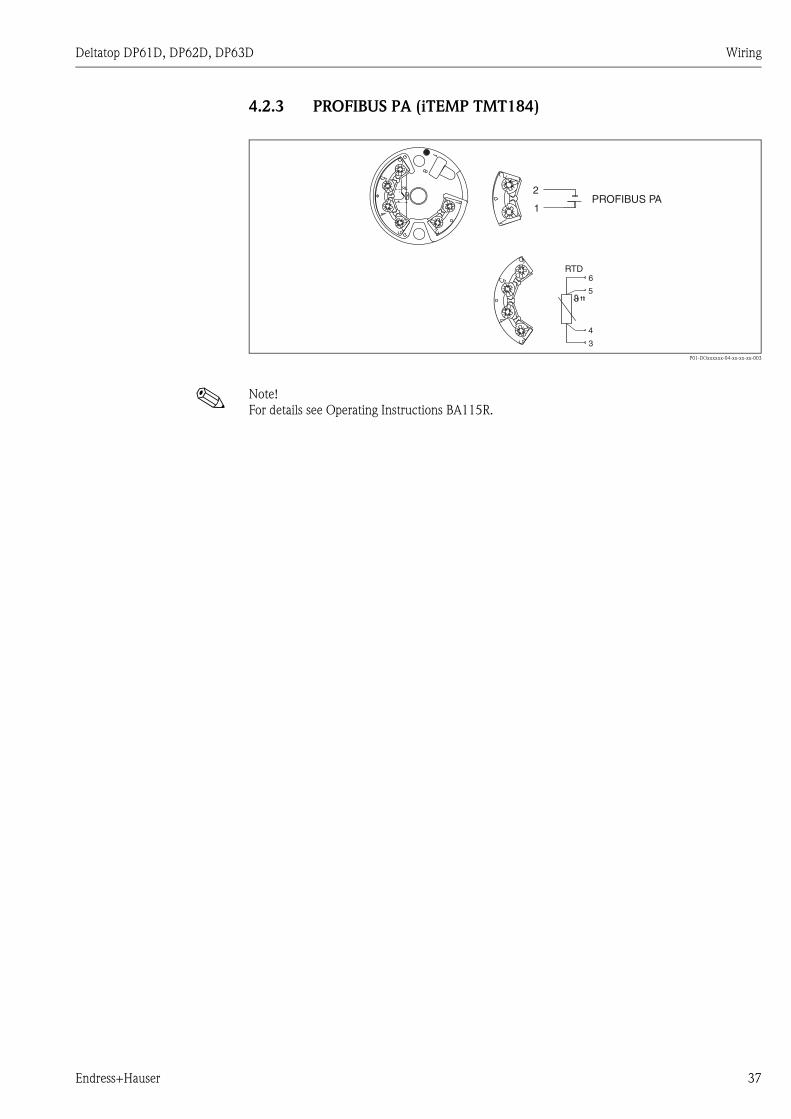
4.2.3 PROFIBUS PA (iTEMP TMT184)
P01-DOxxxxxx-04-xx-xx-xx-003
! Note!
For details see Operating Instructions BA115R.
3
4
5
6RTD
1
2
1
8
PROFIBUS PA
Endress+Hauser 37
Operation and commissioning Deltatop DP61D, DP62D, DP63D
5 Operation and commissioning
5.1 Configuration of the Deltabar S differential pressure
transmitter
The operation of the Deltabar S differential pressure transmitter and the commissioning of the
measurement are described in the following Operating Instructions:
The appropriate Operating Instructions are supplied together with the Deltabar S.
! Note!
If the differential pressure transmitter is ordered with the primary device, then it is completely pre-
configured on delivery. A parametrization is not required in this case.
If an unconfigured differential pressure transmitter is used, the configuration data can be obtained
from the supplied calculation sheet or can be calculated by the "Applicator" selection and sizing tool.
! Note!
The formulae according to which the flow is calculated are summarized in the Appendix (→ ä 55).
5.2 Configuration of a temperature and pressure
compensation
5.2.1 Calculation of the compensated volume or mass flow
• for steam
by Energy Manager RMS621 from Endress+Hauser;
for details see Technical Information TI092R
• for all media
by Flow and Energy Manager RMC621 from Endress+Hauser;
for details see Technical Information TI098R
• for all media
by a PLC;
in this case the compensation calculation has to be programmed by the user.
Communication Operating Instructions
4...20 mA HART BA270P
PROFIBUS PA BA294P
Foundation Fieldbus BA301P
38 Endress+Hauser
Deltatop DP61D, DP62D, DP63D Operation and commissioning
5.2.2 Calculation formula for the temperature and pressure
compensation
At first the starting point for the compensation has to be defined. The starting point is the calculation
sheet, which accompanies every primary element. On the calculation sheet, layout data can be
found for specific operating conditions (pressure and temperature).
The relationship between flow and differential pressure is described by a square root function:
for the mass flow (or volume flow at normal or standard conditions)
and
for the volume flow
where
ρ = the density of the medium.
If the current output of the Deltabar transmitter is set to flow values, the square root function is
already implemented. Otherwise the square root function must be computed externally, e.g. in a
PLC. Please make sure that the square root function is not applied twice.
Ifthe real operating conditions differ from the conditions used in the calculation sheet, the density
of the gas will change and thus also the calculated flow rate will change according to the above-
mentioned formula.
where
P = absolute pressure
T = absolute temperature (K)
Z = compressibility factor
1 = operating condition according to the calculation sheet
2 = actually measured operating condition
The compensation can now be computed as follows:
for the mass flow (or volume flow at standard conditions)
for the volume flow
The compressibility factor Z can be neglected if tis value is close to 1. If the compressibility factor is
to be included in the compensation, the value must be determined according to the actually
measured pressure and temperature. Compressibility factors are available in the corresponding
literature in tables or graphs or can be calculated, e.g. using the Soave-Redlich-Kwong procedure.
2 p� �mQ =
2 p��Q =
v
� �=2 1
P
P
T
T
Z
Z2 1 1
1 2 2
Q = Q2 1
P
P
T
T
Z
Z2 1 1
1 2 2
Q = Q2 1
P
P
T
T
Z
Z1 2 2
2 1 1
Endress+Hauser 39

Operation and commissioning Deltatop DP61D, DP62D, DP63D
5.3 Usage of the accessories
5.3.1 Condensate pots (for steam applications)
Usage
Usage of condensate pots is recommended for gaseous media, which condense when cooling down
in the impulse pipes. This is mainly the case in steam; depending on temperature and pressure it
may also occur in other media (e.g. in alcohols).
Operating principle
Installation and commissioning
• When installing the condensate pots, make sure that they are located at the same height.
Otherwise the zero point adjustment is hardly achievable.
• Before commissioning, the condensate chambers as well as the impulse pipes to the Deltabar
differential pressure transmitter must be completely filled with water. There are different possible
methods for the filling of the condensate chambers:
– through the filling nozzle at the condensate chambers (if present)
– through the condensate drain valve or the venting valve of the Deltabar differential pressure
transmitter. To do so, the impulse lines must be connected to the water supply, e.g. by a hose
connector.
– after the commissioning of the steam pipe wait until the impulse pipes and the condensate
chambers have been filled by themselves with condensate. To do so, the valves at the manifold
have to be closed.
" Caution!
It is essential to avoid any overheating of the Deltabar differential pressure transmitter. Depending
on the steam temperature the temperature at the manifold has to be monitored. If there is any risk
of overheating, the shut-off valves in the impulse pipes must be closed.
! Note!
In any case after filling and after commissioning of the steam supply, wait for stable conditions before
performing the zero point adjustment.
Condensate pots ensure that the impulse lines
are alwas completely filled with liquid and that
the membrane of the transmitter is not exposed
to hot steam. The liquid level is maintained by
condensing steam. Excess condensate flows
back and is re-evaporated.
The usage of condensate pots considerably
reduces fluctuations of the water column. The
stabilized measuring signal and the increased
zero point stability ensure a consistent
measurement quality.
The water column transfers the pressure to the
transmitter membrane.
P01-DOxxxxx-15-xx-xx-xx-007
A. water; B: steam; C: condensing steam; D: excess
condensate flows back
A
B CD
p
40 Endress+Hauser
Deltatop DP61D, DP62D, DP63D Operation and commissioning
5.3.2 Shut-off valves
Usage
Shut-off-valves are used with remote versions for high pressure and high temperature applications.
They are used as a primary shut-off for the measuring point.
Depending on national regulations primary shut-off with two shut-off valves per impulse pipe may
be recommended or required.
Operating principle
The primary shut-off provides separation close to the process between the measuring system and
the measuring pipe in the case of leakages or if maintenance measures are carried out at the impulse
pipes.
Installation and commissioning
After completion of the installation, the shut-off valves must be closed. When starting the
commissioning, the shut-off valves should be opened cautiously and the complete measuring system
should be checked for leakages.
Endress+Hauser 41

Operation and commissioning Deltatop DP61D, DP62D, DP63D
5.3.3 Manifold
Versions
P01-DOxxxxxx-14-xx-xx-xx-014
3-valve manifold
P01-DOxxxxxx-14-xx-xx-xx-015
5-valve manifold; milled
P01-DOxxxxxx-14-xx-xx-xx-016
5-valve manifold; forged
B
A
1 2
31
1
2
23
3
B
A
1 2
3
4 5
1 3 2
4 5
B
A
1 2
3
14 3 2 5
4 5
Valve Application
1, 2 Separates the Deltabar differential pressure transmitter from the process
3 Equalization valve
(zero point adjustment of the Deltabar differential pressure transmitter)
4, 5 • Venting (for liquids and steam)
• Draining (for gases)
• Complete emptying of the impulse pipes (e.g. for maintenance purposes)
42 Endress+Hauser

Deltatop DP61D, DP62D, DP63D Operation and commissioning
Usage
The manifold is used to separate the Deltabar differential pressure transmitter from the process and
to perform the zero point adjustment.
Operating principle
If the Deltabar differential pressure transmitter has to be removed from the measuring point (e.g. for
exchange or repair), it is possible to completely separate the transmitter from the process by closing
all three valves.
Commissioning
During commissioning a zero point adjustment of the Deltabar differential pressure transmitter
should be performed in any case. During the first commissioning, when starting the process, all
valves should be closed. Then, the valves of the "-" and "+" side should be opened cautiously. The
equalization valve remains closed.
After this, make sure that the impulse pipes, the manifold and the transmitter are completely vented
(for liquids and steam) or drained (for gases).
Zero point adjustment
To perform the zero point adjustment, first close the valve at the "-" side and then open the
equalization valve (3), such that the "+" and the "-" side of the transmitter are exposed to the same
static process pressure (+). In this state the zero point adjustment of the Deltabar differential
pressure can be performed (refer to the Operating Instructions of the Deltabar). After completion of
the zero point adjustment the measuring system is put back into operation by performing the same
steps in reverse order.
The zero point adjustment should be checked and - if necessary - adjusted regularly. Also the
measuring system should regularly be checked for complete venting or draining, respectively.
Venting/draining
The additional valves of 5-valve manifolds are used for venting or draining or to empty the impulse
pipes completely (e.g. for maintenance purposes). In steam applications these valves are used to
blow out the impulse pipes.
! Note!
The complete venting or draining of the Deltabar differential pressure transmitter is always
performed by appropriate devices at the side opposite to the transmitter flanges.
" Caution!
If all three valves at the manifold are opened at the same time, the pressure difference may cause a
flow of the medium through the manifold. With hot media this may result in an overheating of the
manifold and of the Deltabar differential pressure transmitter. Therefore, it is essential to avoid
simultaneous opening of all three valves under operating conditions.
Endress+Hauser 43
Troubleshooting Deltatop DP61D, DP62D, DP63D
6 Troubleshooting
6.1 Error messages of the Deltabar S
Error messages of the Deltabar S differential pressure transmitter are described in the following
Operating Instructions:
The appropriate Operating Instructions are supplied together with the Deltabar S.
Communication Operating Instructions
4...20 mA HART BA270P
PROFIBUS PA BA294P
Foundation Fieldbus BA301P
44 Endress+Hauser
Deltatop DP61D, DP62D, DP63D Troubleshooting
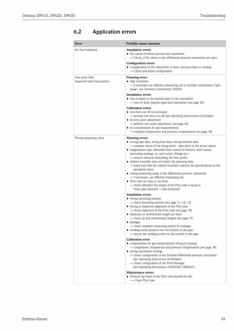
6.2 Application errors
Error Possible cause; measure
No flow indicated Installation errors
• No contact between process and transmitter
-> Check, if the valves to the differential pressure transmitter are open.
Configuration errors
• Configuration of the transmitter or flow calculator false or missing
-> Check and adjust configuration
Zero point drift;
measured value fluctuations
Planning errors
• high turndown
-> if necessary use different measuring cell or mutliple transmitters ("split
range", see Technical Information TI425P)
Installation errors
• Gas or liquid in the impulse pipe/in the transmitter
-> vent or drain impulse pipes and transmitter (see page 43)
Calibration errors
• low-flow-cut-off not activated
-> activate low-flow-cut-off (see Operating Instructions of Deltabar)
• no zero point adjustment
-> perform zero point adjustment (see page 43)
• no compensation for gas measurements
-> complete temperature and pressure compensation (see page 38)
Wrong measuring value Planning errors
• wrong pipe data; wrong flow data; wrong medium data
-> compare values of the sizing sheet - data sheet to the actual values
• inappropriate pipe (disturbed flow caused by fixtures, weld seams,
protruding sealings, in- and outlets, fittings etc.)
-> remove obstacles disturbing the flow profile
• relative humidity does not match the planning data
-> make sure that the relative humidity matches the specifications on the
calculation sheet
• wrong measuring range of the differential pressure transmitter
-> if necessary, use different measuring cell
• Pitot tube too long or too short
-> check whethter the length of the Pitot tube is equal to
"inner pipe diameter + wall thickness"
Installation errors
• wrong mounting position
-> check mounting position (see page 11, 12, 13)
• wrong or imprecise alignment of the Pitot tube
-> check alignment of the Pitot tube (see page 18)
• Upstream or downstream length too short
-> check up and downstream lengths (see page 15)
• leakages
-> check complete measuring system for leakages
• welding socket projects into the interior of the pipe
-> mount the welding socket on the outside ot the pipe
Calibration error
• compensation for gas measurements wrong or missing
-> complement temperature and pressure compensation (see page 38)
• wrong transmitter settings
-> check configuration of the Deltabar differential pressure transmitter
(see Operating Instructions of Deltabar)
-> check configuration of the Flow Manager
(see Operating Instructions of RMC621/RMS621)
Maintenance errors
• Pressure tap holes of the Pitot tube blocked by dirt
--> Clean Pitot tube
Endress+Hauser 45

Maintenance and repairs Deltatop DP61D, DP62D, DP63D
7 Maintenance and repairs
7.1 Maintenance
The following maintenance tasks should be performed in regular intervals:
• Checking of the zero-point adjustment
• for wet gases: drain the condensate
• for soiled media: remove the sediment
• for abrasive media: check the primary device for abrasions
• for build-up formation: check and clean the primary device; exchange gaskets
• after the cutting ring connection has been opened several times (approx. 10 times):
replace the cutting ring
! Note!
Primary elements do not require further maintenance if used appropriately. During standard
revisions of the measuring point it is recommended to examine the primary element carefully to
ensure its funcitonality (material/edge sharpness, traces of wear)
" Caution!
Required maintenace work must be carried out with considerationof the responsible department
and/or trained staff. Security advices of these departments and the staff have to be taken into
account (checking pressure/temperature; valves have to be closed)
" Caution!
If maintenance measures (e.g. exchange of the transmitter or the manifold) have to be carried out
under process conditions, it must be ensured that all valves are closed and that there is no danger
of leaking medium. If necessary, temperature and pressure have to be checked before unmounting
the instrument.
7.2 Exterior cleaning
When cleaning the exterior, always use cleaning agents that do not attack the surface of the housing
and the seals.
7.3 Replacing seals
Under normal circumstances, wetted seals need not to be replaced. Replacement is necessary only
in special circumstances, for example if aggressive or corrosive fluids are incompatible with the seal
material.
46 Endress+Hauser

Deltatop DP61D, DP62D, DP63D Maintenance and repairs
7.4 Spare parts
Material number Description
71071871 Cutting ring DP61D, 316Ti
71071873 Cutting ring DP62D, 316Ti
71071875 Cutting ring DP63D, 316Ti
71071876 End support DP61D, 316Ti
71071879 End support DP62D, 316Ti
71071882 End support DP63D, 316Ti
71071884 End support DP61D, Steel
71071886 End support DP62D, Steel
71071888 End support DP63D, Steel
71071889 Cutting ring connection DP61D, 316Ti
Cutting ring, 316Ti
W/o extension
71071890 Cutting ring connection DP62D, 316Ti
Cutting ring, 316Ti
W/o extension
71071893 Cutting ring connection DP63D, 316Ti
Cutting ring, 316Ti
W/o extension
71071894 Cutting ring connection DP61D, Steel
Cutting ring, Steel
W/o extension
71071895 Cutting ring connection DP62D, Steel
Cutting ring, Steel
W/o extension
71071896 Cutting ring connection DP63D, Steel
Cutting ring, Steel
W/o extension
71071897 Screw set UNF7/16x1-3/4", Steel, Viton
Consists of:
• 4x Screw, length 1-3/4", Steel
• 4x Washer
• 2x Seal Viton
Usage: Manifold DA63M, milled
Not for manifold + connection IEC61518, both side
71071899 Screw set UNF7/16x1-3/4", Steel, PTFE
Consists of:
• 4x Screw, length 1-3/4", Steel
• 4x Washer
• 2x Seal PTFE
Usage: Manifold DA63M, milled
Not for manifold + connection IEC61518, both side
71071900 Screw set UNF7/16x2-1/4", Steel, Viton
Consists of:
• 4x Screw, length 2-1/4", Steel
• 4x Washer
• 2x Seal Viton
Usage: Manifold DA63M, forging
Not for manifold + connection IEC61518, both side
Endress+Hauser 47
Maintenance and repairs Deltatop DP61D, DP62D, DP63D
7.5 Return
The following procedures must be carried out before a transmitter is sent to Endress+Hauser e.g.
for repair or calibration:
• Remove all residue which may be present. Pay special attention to the gasket grooves and crevices
where fluid may be present. This is especially important if the fluid is dangerous to health, e.g.
corrosive, poisonous, carcinogenic, radioactive, etc.
• Always enclose a duly completed "Declaration of contamination" form (a copy of the “Declaration
of contamination” is included at the end of this operating manual). Only then can Endress
+Hauser transport, examine and repair a returned device.
• Enclose special handling instructions if necessary, for example a safety data sheet as per EN 91/
155/EEC.
Additionally specify:
• An exact description of the application.
• The chemical and physical characteristics of the product.
• A short description of the error that occurred (specify error code if possible)
• Operating time of the device.
7.6 Disposal
In case of disposal please seperate the different components according to their material consistence.
7.7 Contact addresses of Endress+Hauser
Contact addresses can be found on our homepage: www.endress.com/worldwide. If you have any
questions, please do not hesitate to contact your Endress+Hauser representative.
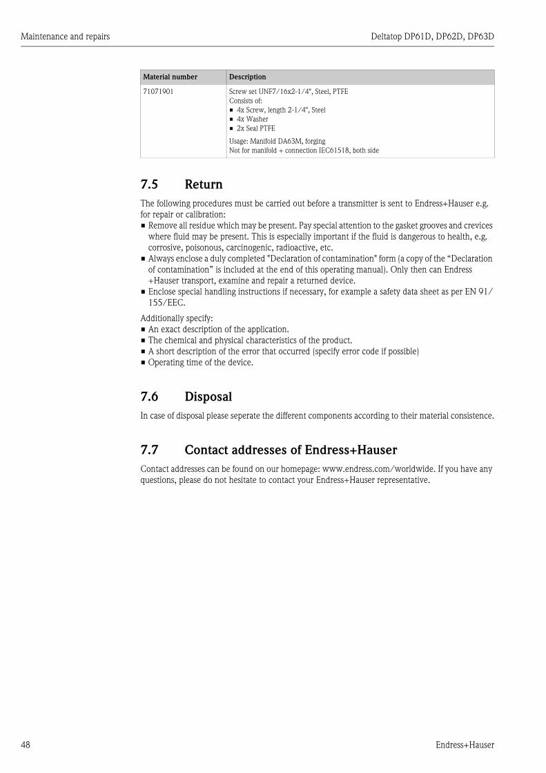
71071901 Screw set UNF7/16x2-1/4", Steel, PTFE
Consists of:
• 4x Screw, length 2-1/4", Steel
• 4x Washer
• 2x Seal PTFE
Usage: Manifold DA63M, forging
Not for manifold + connection IEC61518, both side
Material number Description
48 Endress+Hauser

Deltatop DP61D, DP62D, DP63D Accessories
8 Accessories
8.1 Overview
The following accessories are available for the differential-pressure flow measurement with Pitot
tubes:
• DA62V: Shut-off valves (see Technical Information TI425P)
• DA62C: Condensate pots (see Technical Information TI425P)
• DA63M: Manifold (see Technical Information TI425P)
• DA62P: Purge unit (see page 50)
• PZO: Oval flange adapter (see page 53)
The condensate pots, shut-off valves and manifold can be ordered together with the orifice. They
are included in the product structures DO61W, DO62C , DO63C and DO65F.
Alternatively, they can be ordered by their own product structures. For details refer to Technical
Information TI4252P.
The purge unit can only be ordered by its own product structure.
Endress+Hauser 49
Accessories Deltatop DP61D, DP62D, DP63D
8.2 Purge unit DA62P
8.2.1 Usage
With flow measurements of waste gases or soiled air, solid particles often settle at the profile of the
Pitot tube and, depending on the degree of soiling, reduce the measuring accuracy or even inhibit
the functionality of the Pitot tube.
In many applications, regular manual cleaning of the Pitot tube is no feasible solution. Demounting
of the probe, thourough cleaning and remounting often are too cost-intensive and time-consuming.
Furthermore no measuring data are available during the cleaning procedure.
The purge unit DA62P helps to perform a fully automatic and effortless cleaning.
Usage of the purge unit is recommended if the solid contents exceeds 100 mg/m3. The usability of
the purge unit is limited for moist or adhering solids.
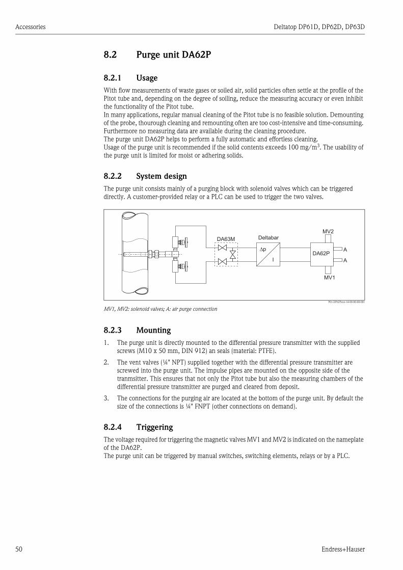
8.2.2 System design
The purge unit consists mainly of a purging block with solenoid valves which can be triggered
directly. A customer-provided relay or a PLC can be used to trigger the two valves.
P01-DP62Pxxx-14-00-00-00-001
MV1, MV2: solenoid valves; A: air purge connection
8.2.3 Mounting
1. The purge unit is directly mounted to the differential pressure transmitter with the supplied
screws (M10 x 50 mm, DIN 912) an seals (material: PTFE).
2. The vent valves (¼" NPT) supplied together with the differential pressure transmitter are
screwed into the purge unit. The impulse pipes are mounted on the opposite side of the
tranmsitter. This ensures that not only the Pitot tube but also the measuring chambers of the
differential pressure transmitter are purged and cleared from deposit.
3. The connections for the purging air are located at the bottom of the purge unit. By default the
size of the connections is ¼" FNPT (other connections on demand).
8.2.4 Triggering
The voltage required for triggering the magnetic valves MV1 and MV2 is indicated on the nameplate
of the DA62P.
The purge unit can be triggered by manual switches, switching elements, relays or by a PLC.
Δp
I
Deltabar
DA62P
MV1
MV2
DA63M
A
A
50 Endress+Hauser

Deltatop DP61D, DP62D, DP63D Accessories
8.2.5 Technical data
Type of valve 2-way valve, directly triggered
Medium air
Operating mode normally closed
Pipe connection ¼" NPT
Mounting position arbitrary
Nominal diameter • Non-Ex area: 3 mm (0.12")
• ATEX: 2 mm (0.08 ")
flow coefficient Kv approx. 0,23 m3/h
Difference of operating
pressure
• Non-Ex area: max. 6 bar (87 psi)
• ATEX: max. 5 bar (72 psi)
Overall height of lift 1 mm (0.04")
Leak rate bubble tight
Temperature of medium • Non-Ex area: -10 ... +90 °C (14 ... +194 °F)
• ATEX: -10 ... +100 °C (14 ... 212 °F) for temperature class T6
Ambient temperature • Non-Ex area: max 55 °C (131 °F)
• ATEX: -30 ... +60 °C (-22 ... +140 °F) für Einezlmontage
Material of valve chamber • anodically oxidized aluminium
• stainless steel
Material of inner parts stainless steel
Material of seals FPM
Nominal voltage • 230 VAC, 50 Hz
• 115 V AC, 50 Hz
• 24 VDC
Protection class for the ATEX version : EEx M II 2G/Dn T4; EEx EM II 2G/D T4
(PTB 00 ATEX 2129X)
On-time 100 %
Type of protection IP65
Electrical connection • Non-Ex area: according to DIN 43650
• ATEX: expansion-fit cable (3000 mm)
Power consumption • Non-Ex area: 21 VA AC (pick up); 12 VA / 8W (operation)
• ATEX: 7 W
Weight approx. 2,7 kg (6 lbs)
Endress+Hauser 51
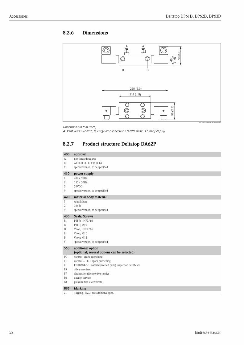
Accessories Deltatop DP61D, DP62D, DP63D
8.2.6 Dimensions
P01-DA62Pxxx-06-00-00-00-001
Dimensions in mm (inch)
A: Vent valves ¼"NPT; B: Purge air connections "FNPT (max. 3,5 bar [50 psi])
8.2.7 Product structure Deltatop DA62P
228 (9.0)
114 (4.5)
58
(2.3
)40
(1.6
)
70
(2.8
)
A A
B B
400 approval
A non-hazardous area
B ATEX II 2G EEx m II T4
Y special version, to be specified
410 power supply
1 230V 50Hz
2 115V 50Hz
3 24VDC
9 special version, to be specified
420 material body material
1 Aluminium
2 316Ti
9 special version, to be specified
430 Seals; Screws
B PTFE; UNF7/16
C PTFE; M10
D Viton; UNF7/16
E Viton; M10
F Viton; M12
Y special version, to be specified
550 additional option
(optional; several options can be selected)
FG varistor, spark quenching
FH varistor + LED, spark quenching
F1 EN10204-3.1 material (wetted parts) inspection certificate
F5 oil+grease free
F7 cleaned for silicone-free service
F6 oxygen service
F8 pressure test + certificate
895 Marking
Z1 Tagging (TAG), see additional spec.
52 Endress+Hauser

Deltatop DP61D, DP62D, DP63D Accessories
8.3 Oval flange adapter PZO
8.3.1 Dimensions
P01-DOxxxxx-15-xx-xx-xx-022
8.3.2 Product structure PZO
010 Approval
R Basic version
B EN10204-3.1 material, oval flange inspection certificate
S Cleaned from oil+grease, oxygen service
020 Process Connection
A FNPT1/2-14
030 Material
2 Steel C22.8
1 316L
040 Seal
1 PTFE
2 FKM Viton
050 Mounting Screw
1 2x Mounting screw M10
4 2x Mounting screw M12
2 2x Mounting screw UNF7/16-20
3 Not selected
41
.3(1
.63
)
12 (0.47)
Endress+Hauser 53

Appendix Deltatop DP61D, DP62D, DP63D
9 Appendix
9.1 Measuring principle
P01-DOxxx-15-00-00-xx-002
The front of the pitot tube is exposed to the static pressure pstat plus the dynamic pressure pdyn. The
back of the tube is exposed only to the static pressure pstat. The resulting differential pressure Δp
can be used to calculate the flow rate Q.
The relationship between flow rate (Q) and differential pressure (Δp) is given by a square root
function:
P01-DOxxxxx-15-xx-xx-xx-008
Downstream of the Pitot tube the static pressure pstat is reduced by the permanent pressure loss Δω.
With Pitot tubes this pressure loss Δω is much less significant than with other primary elements.
+ +– –
�p
p +pdyn stat pstat
pΔQ ~
54 Endress+Hauser
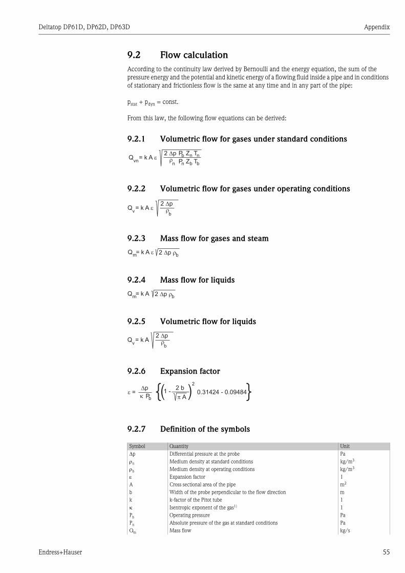
Deltatop DP61D, DP62D, DP63D Appendix
9.2 Flow calculation
According to the continuity law derived by Bernoulli and the energy equation, the sum of the
pressure energy and the potential and kinetic energy of a flowing fluid inside a pipe and in conditions
of stationary and frictionless flow is the same at any time and in any part of the pipe:
pstat + pdyn = const.
From this law, the following flow equations can be derived:
9.2.1 Volumetric flow for gases under standard conditions
9.2.2 Volumetric flow for gases under operating conditions
9.2.3 Mass flow for gases and steam
9.2.4 Mass flow for liquids
9.2.5 Volumetric flow for liquids
9.2.6 Expansion factor
9.2.7 Definition of the symbols
Symbol Quantity Unit
Δp Differential pressure at the probe Pa
ρn Medium density at standard conditions kg/m3
ρb Medium density at operating conditions kg/m3
ε Expansion factor 1
A Cross sectional area of the pipe m2
b Width of the probe perpendicular to the flow direction m
k k-factor of the Pitot tube 1
κ Isentropic exponent of the gas1) 1
Pb Operating pressure Pa
Pn Absolute pressure of the gas at standard conditions Pa
Qm Mass flow kg/s
2 p��Q = k A �
vn
Pb Z Tnn
Pn Z Tbbn
2 p��Q = k A �
vb
2 p� �mk A �
bQ =
2 p� �mk A
bQ =
2 p��Q = k A
vb
�p
�� =
Pb � A
2 b1 -
2
0.31424 - 0.09484{( ( {
Endress+Hauser 55
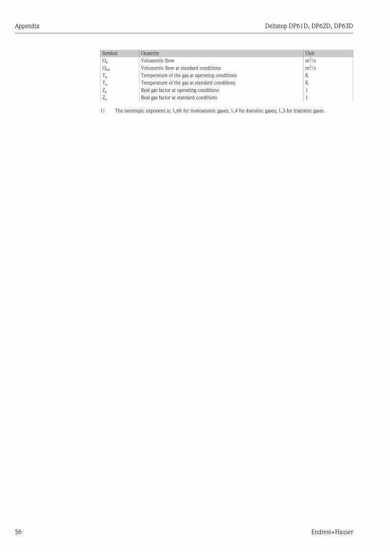
Appendix Deltatop DP61D, DP62D, DP63D
Qv Volumetric flow m3/s
Qvn Volumetric flow at standard conditions m3/s
Tb Temperature of the gas at operating conditions K
Tn Temperature of the gas at standard conditions K
Zb Real gas factor at operating conditions 1
Zn Real gas factor at standard conditions 1
1) The isentropic exponent is: 1,66 for monoatomic gases; 1,4 for diatomic gases; 1,3 for triatomic gases
Symbol Quantity Unit
56 Endress+Hauser

Deltatop DP61D, DP62D, DP63D Index
Index
Aabsolute pressure. . . . . . . . . . . . . . . . . . . . . . . . . . . . . . . . 17
Ccalculation formula . . . . . . . . . . . . . . . . . . . . . . . . . . . . . . 39
CE mark . . . . . . . . . . . . . . . . . . . . . . . . . . . . . . . . . . . . . . . 9
cleaning . . . . . . . . . . . . . . . . . . . . . . . . . . . . . . . . . . . . . . 46
compensation . . . . . . . . . . . . . . . . . . . . . . . . . . . . . . . . . . 39
connection . . . . . . . . . . . . . . . . . . . . . . . . . . . . . . . . . . . . 36
cutting ring version . . . . . . . . . . . . . . . . . . . . . . . . . . . . . . 20
Ddeclaration of conformity. . . . . . . . . . . . . . . . . . . . . . . . . . . 9
declaration of contamination . . . . . . . . . . . . . . . . . . . . . . . 48
Deltabar S . . . . . . . . . . . . . . . . . . . . . . . . . . . . . . . . . . 35, 38
downstream length . . . . . . . . . . . . . . . . . . . . . . . . . . . . . . 15
Fflange mounting . . . . . . . . . . . . . . . . . . . . . . . . . . . . . . . . 30
flange version . . . . . . . . . . . . . . . . . . . . . . . . . . . . . . . . . . 22
four-wire terminal block . . . . . . . . . . . . . . . . . . . . . . . . . . 36
Ggases . . . . . . . . . . . . . . . . . . . . . . . . . . . . . . . . . . . . . . . . . 12
HHART . . . . . . . . . . . . . . . . . . . . . . . . . . . . . . . . . . . . . . . . 36
hazardous area . . . . . . . . . . . . . . . . . . . . . . . . . . . . . . . . . . 4
heat insulation . . . . . . . . . . . . . . . . . . . . . . . . . . . . . . . . . 16
Lliquids. . . . . . . . . . . . . . . . . . . . . . . . . . . . . . . . . . . . . . . . 11
Mmass flow . . . . . . . . . . . . . . . . . . . . . . . . . . . . . . . . . . . . . 38
measuring range . . . . . . . . . . . . . . . . . . . . . . . . . . . . . . . . 18
Nnameplate . . . . . . . . . . . . . . . . . . . . . . . . . . . . . . . . . . . . . . 6
Ppressure compensation . . . . . . . . . . . . . . . . . . . . . . . . 17, 38
Profibus . . . . . . . . . . . . . . . . . . . . . . . . . . . . . . . . . . . . . . 37
Pt100 . . . . . . . . . . . . . . . . . . . . . . . . . . . . . . . . . . . . . . . . 36
purge unit . . . . . . . . . . . . . . . . . . . . . . . . . . . . . . . . . . . . . 50
Rreturn . . . . . . . . . . . . . . . . . . . . . . . . . . . . . . . . . . . . . . . . 48
Ssafety chain . . . . . . . . . . . . . . . . . . . . . . . . . . . . . . . . . . . . 24
spindle . . . . . . . . . . . . . . . . . . . . . . . . . . . . . . . . . . . . . . . 27
steam . . . . . . . . . . . . . . . . . . . . . . . . . . . . . . . . . . . . . . . . 13
Ttemperature compensation . . . . . . . . . . . . . . . . . . . . . . . . 17
temperature sensor . . . . . . . . . . . . . . . . . . . . . . . . . . . . . . 36
Endress+Hauser
Uupstream length. . . . . . . . . . . . . . . . . . . . . . . . . . . . . . . . . 15
Vvolume flow . . . . . . . . . . . . . . . . . . . . . . . . . . . . . . . . . . . 38
57

Deltatop DP61D, DP62D, DP63D Index
58
Endress+Hauser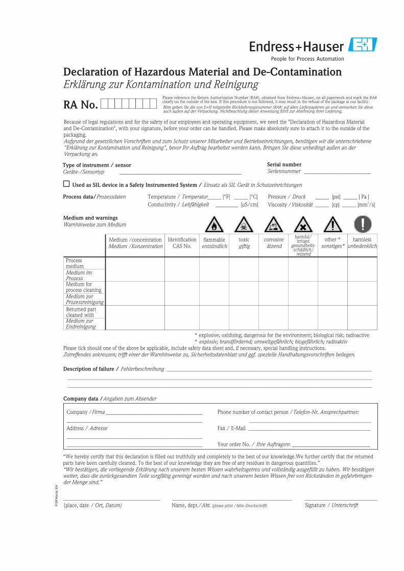
P/S
F/K
onta
XIV
Because of legal regulations and for the safety of our employees and operating equipment, we need the "Declaration of Hazardous Materialand De-Contamination", with your signature, before your order can be handled. Please make absolutely sure to attach it to the outside of thepackaging.Aufgrund der gesetzlichen Vorschriften und zum Schutz unserer Mitarbeiter und Betriebseinrichtungen, benötigen wir die unterschriebene"Erklärung zur Kontamination und Reinigung", bevor Ihr Auftrag bearbeitet werden kann. Bringen Sie diese unbedingt außen an derVerpackung an.
Serial number
Seriennummer ________________________Type of instrument / sensor
Geräte-/Sensortyp ____________________________________________
Process data/Prozessdaten Temperature _____ [°F] [°C]
Conductivity / ________
_____
Leitfähigkeit
/
[μS/cm]
Temperatur Pressure _____ [psi] [ Pa ]
Viscosity _____ [cp] [mm /s]
_____
_____
/
/
Druck
Viskosität2
corrosiveätzend
harmlessunbedenklich
other *sonstiges*
toxicgiftig
Processmedium
IdentificationCAS No.
flammableentzündlich
harmful/irritant
gesundheits-schädlich/
reizend
Medium /concentrationMedium /Konzentration
Returned partcleaned with
Medium forprocess cleaning
Medium and warnings
Warnhinweise zum Medium
* explosive; oxidising; dangerous for the environment; biological risk; radioactive* explosiv; brandfördernd; umweltgefährlich; biogefährlich; radioaktiv
Please tick should one of the above be applicable, include safety data sheet and, if necessary, special handling instructions.Zutreffendes ankreuzen; trifft einer der Warnhinweise zu, Sicherheitsdatenblatt und ggf. spezielle Handhabungsvorschriften beilegen.
Description of failure / Fehlerbeschreibung __________________________________________________________________________
______________________________________________________________________________________________________________
______________________________________________________________________________________________________________
“We hereby certify that this declaration is filled out truthfully and completely to the best of our knowledge.We further certify that the returnedparts have been carefully cleaned. To the best of our knowledge they are free of any residues in dangerous quantities.”“Wir bestätigenw
bestätigen, die vorliegende Erklärung nach unserem besten Wissen wahrheitsgetreu und vollständig ausgefüllt zu haben. Wireiter, dass die zurückgesandten Teile sorgfältig gereinigt wurden und nach unserem besten Wissen frei von Rückständen in gefahrbringen-
der Menge sind.”
(place, date / Ort, Datum)
Company data /Angaben zum Absender
Company / ________________________________
_________________________________________________
Address /
_________________________________________________
_________________________________________________
Firma ___
Adresse
Phone number of contact person /
____________________________________________
Fax / E-Mail ____________________________________________
Your order No. / ____________________________
Telefon-Nr. Ansprechpartner:
Ihre Auftragsnr.
Medium zurEndreinigung
Medium zurProzessreinigung
Medium imProzess
Used as SIL device in a Safety Instrumented System / Einsatz als SIL Gerät in Schutzeinrichtungen
RA No.
Erklärung zur Kontamination und ReinigungDeclaration of Hazardous Material and De-Contamination
Please reference the Return Authorization Number (RA#), obtained from Endress+Hauser, on all paperwork and mark the RA#clearly on the outside of the box. If this procedure is not followed, it may result in the refusal of the package at our facility.
Bitte geben Sie die von E+H mitgeteilte Rücklieferungsnummer (RA#) auf allen Lieferpapieren an und vermerken Sie dieseauch außen auf der Verpackung. Nichtbeachtung dieser Anweisung führt zur Ablehnung ihrer Lieferung.
Name, dept./Abt. (please print / )bitte Druckschrift Signature / Unterschrift

www.endress.com/worldwide
BA369P/00/en/07.08
CCS/FM+SGML 6.0/ProMoDo
71062450Top Related