


Languages
Pages
Legal


Part No. 060328-10, Rev. AApril 2011
OmniSwitch AOS Release 6 Advanced Routing
Configuration Guide
www.alcatel-lucent.com

This user guide documents release 6.4.4 of the OmniSwitch 6850 Series, OmniSwitch 6855 Series, OmniSwitch 6850E Series, and OmniSwitch 9000E Series
The functionality described in this guide is subject to change without notice.
Copyright © 2011 by Alcatel-Lucent. All rights reserved. This document may not be reproduced in whole or in part without the express written permission of Alcatel-Lucent.
Alcatel-Lucent® and the Alcatel-Lucent logo are registered trademarks of Alcatel-Lucent. Xylan®, OmniSwitch®, OmniStack®, and Alcatel-Lucent OmniVista® are registered trademarks of Alcatel-Lucent.
OmniAccess™, Omni Switch/Router™, PolicyView™, RouterView™, SwitchManager™, VoiceView™, WebView™, X-Cell™, X-Vision™, and the Xylan logo are trademarks of Alcatel-Lucent.
This OmniSwitch product contains components which may be covered by one or more of the following U.S. Patents:
• U.S. Patent No. 6,339,830 • U.S. Patent No. 6,070,243 • U.S. Patent No. 6,061,368 • U.S. Patent No. 5,394,402• U.S. Patent No. 6,047,024• U.S. Patent No. 6,314,106• U.S. Patent No. 6,542,507• U.S. Patent No. 6,874,090
26801 West Agoura RoadCalabasas, CA 91301
(818) 880-3500 FAX (818) [email protected]
US Customer Support—(800) 995-2696International Customer Support—(818) 878-4507
Internet—eservice.ind.alcatel.com
ii OmniSwitch AOS Release 6 Advanced Routing Configuration Guide April 2011
Contents
About This Guide ....................................................................................................... xvii
Supported Platforms ....................................................................................................... xvii
Who Should Read this Manual? ....................................................................................xviii
When Should I Read this Manual? ................................................................................xviii
What is in this Manual? .................................................................................................xviii
What is Not in this Manual? ..........................................................................................xviii
How is the Information Organized? ................................................................................ xix
Documentation Roadmap ................................................................................................ xix
Related Documentation ................................................................................................... xxi
User Manual CD ...........................................................................................................xxiii
Technical Support .........................................................................................................xxiii
Chapter 1 Configuring OSPF .......................................................................................................1-1
In This Chapter ................................................................................................................1-1
OSPF Specifications ........................................................................................................1-2
OSPF Defaults Table .......................................................................................................1-3
OSPF Quick Steps ...........................................................................................................1-4
OSPF Overview ..............................................................................................................1-7OSPF Areas ..............................................................................................................1-8Classification of Routers ..........................................................................................1-9Virtual Links ............................................................................................................1-9Stub Areas ..............................................................................................................1-10
Not-So-Stubby-Areas ......................................................................................1-11Totally Stubby Areas .......................................................................................1-11
Equal Cost Multi-Path (ECMP) Routing ...............................................................1-12Non Broadcast OSPF Routing ................................................................................1-12Graceful Restart on Stacks with Redundant Switches ...........................................1-13Graceful Restart on Switches with Redundant CMMs ..........................................1-14
Configuring OSPF .........................................................................................................1-15Preparing the Network for OSPF ...........................................................................1-16Activating OSPF ....................................................................................................1-16Creating an OSPF Area ..........................................................................................1-17Configuring Stub Area Default Metrics .................................................................1-19Creating OSPF Interfaces .......................................................................................1-20Interface Authentication .........................................................................................1-21Creating Virtual Links ............................................................................................1-22Configuring Redistribution ....................................................................................1-23
OmniSwitch AOS Release 6 Advanced Routing Configuration Guide April 2011 iii
Contents
Using Route Maps ...........................................................................................1-24Configuring Route Map Redistribution ...........................................................1-27Route Map Redistribution Example ................................................................1-29
Configuring Router Capabilities ............................................................................1-30Configuring Static Neighbors .................................................................................1-31Configuring Redundant Switches in a Stack for Graceful Restart .........................1-32Configuring Redundant CMMs for Graceful Restart .............................................1-33
OSPF Application Example ..........................................................................................1-34Step 1: Prepare the Routers .............................................................................1-35Step 2: Enable OSPF .......................................................................................1-36Step 3: Create the Areas and Backbone ..........................................................1-36Step 4: Create, Enable, and Assign Interfaces .................................................1-37Step 5: Examine the Network ..........................................................................1-38
Verifying OSPF Configuration .....................................................................................1-39
Chapter 2 Configuring OSPFv3 ...................................................................................................2-1
In This Chapter ................................................................................................................2-1
OSPFv3 Specifications ....................................................................................................2-2
OSPFv3 Defaults Table ...................................................................................................2-3
OSPFv3 Quick Steps .......................................................................................................2-4
OSPFv3 Overview ..........................................................................................................2-8OSPFv3 Areas ..........................................................................................................2-9Classification of Routers ........................................................................................2-10Virtual Links ..........................................................................................................2-10Stub Areas ..............................................................................................................2-11Equal Cost Multi-Path (ECMP) Routing ...............................................................2-12
Configuring OSPFv3 .....................................................................................................2-13Preparing the Network for OSPFv3 .......................................................................2-14Activating OSPFv3 ................................................................................................2-14Creating an OSPFv3 Area ......................................................................................2-15Configuring Stub Area Default Metrics .................................................................2-16Creating OSPFv3 Interfaces ...................................................................................2-16Creating Virtual Links ............................................................................................2-17Configuring Redistribution ....................................................................................2-18
Using Route Maps ...........................................................................................2-19Configuring Route Map Redistribution ...........................................................2-22
Configuring Router Capabilities ............................................................................2-24
OSPFv3 Application Example ......................................................................................2-25Step 1: Prepare the Routers .............................................................................2-26Step 2: Load OSPFv3 ......................................................................................2-27Step 3: Create the Areas and Backbone ..........................................................2-28Step 5: Examine the Network ..........................................................................2-29
Verifying OSPFv3 Configuration .................................................................................2-30
iv OmniSwitch AOS Release 6 Advanced Routing Configuration Guide April 2011

Contents
Chapter 3 Configuring IS-IS ........................................................................................................3-1
In This Chapter ................................................................................................................3-1
IS-IS Specifications .........................................................................................................3-2
IS-IS Defaults Table ........................................................................................................3-3
IS-IS Quick Steps ............................................................................................................3-5
IS-IS Overview ................................................................................................................3-8IS-IS Packet Types .................................................................................................3-10IS-IS Areas .............................................................................................................3-10Graceful Restart on Stacks with Redundant Switches ...........................................3-12
Configuring IS-IS ..........................................................................................................3-14Preparing the Network for IS-IS ............................................................................3-14Activating IS-IS ......................................................................................................3-15Creating an IS-IS Area ID ......................................................................................3-15Creating IS-IS Interfaces ........................................................................................3-16Configuring the IS-IS Level ...................................................................................3-16Enabling Summarization ........................................................................................3-18Enabling IS-IS Authentication ...............................................................................3-18Modifying Interface Parameters .............................................................................3-21Configuring Redistribution Using Route Maps .....................................................3-22
Using Route Maps ...........................................................................................3-23Configuring Route Map Redistribution ...........................................................3-26Route Map Redistribution Example ................................................................3-27
Configuring Router Capabilities ............................................................................3-28Configuring Redundant Switches in a Stack for Graceful Restart .........................3-28
IS-IS Application Example ...........................................................................................3-29Step 1: Prepare the Routers .............................................................................3-29Step 2: Enable IS-IS ........................................................................................3-30Step 3: Create and Enable Area ID ..................................................................3-30Step 4: Configuring IS-IS Level Capability ....................................................3-30Step 5: Create, Enable, and Assign Interfaces .................................................3-30Step 6: Examine the Network ..........................................................................3-31
Verifying IS-IS Configuration ......................................................................................3-31
Chapter 4 Configuring BGP .........................................................................................................4-1
In This Chapter ................................................................................................................4-1
BGP Specifications ........................................................................................................4-3
Quick Steps for Using BGP ............................................................................................4-4
BGP Overview ................................................................................................................4-5Autonomous Systems (ASs) .....................................................................................4-6Internal vs. External BGP .........................................................................................4-7Communities ............................................................................................................4-8Route Reflectors .......................................................................................................4-9BGP Confederations ...............................................................................................4-11Policies ...................................................................................................................4-12
Regular Expressions ........................................................................................4-13
OmniSwitch AOS Release 6 Advanced Routing Configuration Guide April 2011 v

Contents
The Route Selection Process ..................................................................................4-16Route Dampening ...................................................................................................4-17CIDR Route Notation .............................................................................................4-17
BGP Configuration Overview .......................................................................................4-18
Starting BGP .................................................................................................................4-19Disabling BGP ........................................................................................................4-19
Setting Global BGP Parameters ....................................................................................4-20Setting the Router AS Number ...............................................................................4-21Setting the Default Local Preference .....................................................................4-21Enabling AS Path Comparison ...............................................................................4-22Controlling the use of MED Values .......................................................................4-23Synchronizing BGP and IGP Routes .....................................................................4-24Displaying Global BGP Parameters .......................................................................4-25
Configuring a BGP Peer ................................................................................................4-26Creating a Peer .......................................................................................................4-28Restarting a Peer .....................................................................................................4-29Setting the Peer Auto Restart .................................................................................4-29Changing the Local Router Address for a Peer Session .........................................4-30Clearing Statistics for a Peer ..................................................................................4-30Setting Peer Authentication ....................................................................................4-31Setting the Peer Route Advertisement Interval ......................................................4-31
Configuring a BGP Peer with the Loopback0 Interface ..................................4-31
Configuring Aggregate Routes .....................................................................................4-32
Configuring Local Routes (Networks) ..........................................................................4-33Adding the Network ........................................................................................4-33Configuring Network Parameters ....................................................................4-34Viewing Network Settings ..............................................................................4-35
Controlling Route Flapping Through Route Dampening ..............................................4-36Example: Flapping Route Suppressed, then Unsuppressed ............................4-36Enabling Route Dampening ............................................................................4-37Configuring Dampening Parameters ...............................................................4-37Clearing the History ........................................................................................4-39Displaying Dampening Settings and Statistics ................................................4-39
Setting Up Route Reflection .........................................................................................4-40Configuring Route Reflection ................................................................................4-42Redundant Route Reflectors ...................................................................................4-42
Working with Communities ..........................................................................................4-43
Creating a Confederation ..............................................................................................4-44
Routing Policies ............................................................................................................4-45Creating a Policy ....................................................................................................4-45Assigning a Policy to a Peer ...................................................................................4-50Displaying Policies .................................................................................................4-52
Configuring Redistribution ...........................................................................................4-53Using Route Maps ...........................................................................................4-53Configuring Route Map Redistribution ...........................................................4-57Route Map Redistribution Example ................................................................4-58
vi OmniSwitch AOS Release 6 Advanced Routing Configuration Guide April 2011
Contents
Configuring Redundant CMMs for Graceful Restart .............................................4-59
Application Example .....................................................................................................4-60AS 100 .............................................................................................................4-60AS 200 .............................................................................................................4-61AS 300 .............................................................................................................4-62
Displaying BGP Settings and Statistics ........................................................................4-63
BGP for IPv6 Overview ................................................................................................4-64
Quick Steps for Using BGP for IPv6 ............................................................................4-66
Configuring BGP for IPv6 ............................................................................................4-68Enabling/Disabling IPv6 BGP Unicast ..................................................................4-68Configuring an IPv6 BGP Peer ..............................................................................4-68
Changing the Local Router Address for an IPv6 Peer Session .......................4-71Optional IPv6 BGP Peer Parameters ...............................................................4-72
Configuring IPv6 BGP Networks ..........................................................................4-72Adding a Network ...........................................................................................4-72Enabling a Network .........................................................................................4-73Configuring Network Parameters ....................................................................4-73Viewing Network Settings ..............................................................................4-74
Configuring IPv6 Redistribution ...................................................................................4-75Using Route Maps for IPv6 Redistribution ............................................................4-75
Configuring IPv6 Route Map Redistribution ..................................................4-75
IPv6 BGP Application Example ...................................................................................4-77AS 100 .............................................................................................................4-77AS 200 .............................................................................................................4-79AS 300 .............................................................................................................4-80
Displaying IPv6 BGP Settings and Statistics ................................................................4-81
Chapter 5 Configuring Multicast Address Boundaries ........................................................5-1
In This Chapter ................................................................................................................5-1
Multicast Boundary Specifications .................................................................................5-2
Quick Steps for Configuring Multicast Address Boundaries ..........................................5-3Using Existing IP Interfaces ..............................................................................5-3On New IP Interface ..........................................................................................5-3
Multicast Address Boundaries Overview ........................................................................5-4Multicast Addresses and the IANA ..........................................................................5-4
Administratively Scoped Multicast Addresses ..................................................5-4Source-Specific Multicast Addresses ................................................................5-4
Multicast Address Boundaries .................................................................................5-5Concurrent Multicast Addresses ..............................................................................5-6
Configuring Multicast Address Boundaries ....................................................................5-7Basic Multicast Address Boundary Configuration ...................................................5-7Creating a Multicast Address Boundary ..................................................................5-7Deleting a Multicast Address Boundary ..................................................................5-7
OmniSwitch AOS Release 6 Advanced Routing Configuration Guide April 2011 vii
Contents
Verifying the Multicast Address Boundary Configuration .............................................5-8
Application Example for Configuring Multicast Address Boundaries ...........................5-8
Chapter 6 Configuring DVMRP ...................................................................................................6-1
In This Chapter ................................................................................................................6-1
DVMRP Specifications ...................................................................................................6-2
DVMRP Defaults ............................................................................................................6-2
Quick Steps for Configuring DVMRP ............................................................................6-3
DVMRP Overview ..........................................................................................................6-4Reverse Path Multicasting ........................................................................................6-4Neighbor Discovery .................................................................................................6-5Multicast Source Location, Route Report Messages, and Metrics ..........................6-6Dependent Downstream Routers and Poison Reverse .............................................6-6Pruning Multicast Traffic Delivery ..........................................................................6-7Grafting Branches Back onto the Multicast Delivery Tree ......................................6-7DVMRP Tunnels ......................................................................................................6-8
Configuring DVMRP ......................................................................................................6-9Enabling DVMRP on the Switch .............................................................................6-9
Loading DVMRP into Memory .........................................................................6-9Enabling DVMRP on a Specific Interface ......................................................6-10Viewing DVMRP Status and Parameters for a Specific Interface ..................6-11Globally Enabling DVMRP on the Switch .....................................................6-11Checking the Current Global DVMRP Status .................................................6-11Automatic Loading and Enabling of DVMRP Following a System Boot ......6-12
Neighbor Communications ....................................................................................6-12Routes .....................................................................................................................6-13Pruning ...................................................................................................................6-14
More About Prunes ..........................................................................................6-14Grafting ..................................................................................................................6-16Tunnels ...................................................................................................................6-16
Verifying the DVMRP Configuration ...........................................................................6-17
Chapter 7 Configuring PIM ..........................................................................................................7-1
In This Chapter ................................................................................................................7-1
PIM Specifications ..........................................................................................................7-3
PIM Defaults ...................................................................................................................7-4
Quick Steps for Configuring PIM-DM ...........................................................................7-6
PIM Overview .................................................................................................................7-8PIM-Sparse Mode (PIM-SM) ...................................................................................7-8
Rendezvous Points (RPs) ..................................................................................7-8Bootstrap Routers (BSRs) .................................................................................7-9Designated Routers (DRs) .................................................................................7-9Shared (or RP) Trees .........................................................................................7-9Avoiding Register Encapsulation ....................................................................7-12
PIM-Dense Mode (PIM-DM) .................................................................................7-12
viii OmniSwitch AOS Release 6 Advanced Routing Configuration Guide April 2011
Contents
RP Initiation of (S, G) Source-Specific Join Message ...........................................7-13SPT Switchover ......................................................................................................7-15PIM-SSM Support ..................................................................................................7-17
Source-Specific Multicast Addresses ..............................................................7-17
Configuring PIM ...........................................................................................................7-18Enabling PIM on the Switch ..................................................................................7-18
Verifying the Software ....................................................................................7-18Loading PIM into Memory ..............................................................................7-19Enabling IPMS ................................................................................................7-19
Enabling PIM on a Specific Interface ....................................................................7-20Disabling PIM on a Specific Interface ............................................................7-20Viewing PIM Status and Parameters for a Specific Interface .........................7-21
Enabling PIM Mode on the Switch ........................................................................7-21Disabling PIM Mode on the Switch ................................................................7-21Checking the Current Global PIM Status ........................................................7-22
Mapping an IP Multicast Group to a PIM Mode ...................................................7-22Mapping an IP Multicast Group to PIM-DM ..................................................7-22Mapping an IP Multicast Group to PIM-SSM ................................................7-22Verifying Group Mapping ...............................................................................7-23
Automatic Loading and Enabling of PIM after a System Reboot ..........................7-23PIM Bootstrap and RP Discovery ..........................................................................7-24
Configuring a C-RP .........................................................................................7-24Specifying the Maximum Number of RPs ......................................................7-25Candidate Bootstrap Routers (C-BSRs) ..........................................................7-25Bootstrap Routers (BSRs) ...............................................................................7-26Configuring Static RP Groups .........................................................................7-27Group-to-RP Mapping .....................................................................................7-28
Configuring Keepalive Period ................................................................................7-28Verifying Keepalive Period .............................................................................7-29
Configuring Notification Period .............................................................................7-29Verifying the Notification Period ....................................................................7-30
Verifying PIM Configuration ........................................................................................7-31
PIM for IPv6 Overview .................................................................................................7-32IPv6 PIM-SSM Support .........................................................................................7-32
Source-Specific Multicast Addresses ..............................................................7-32
Quick Steps for Configuring IPv6 PIM-DM .................................................................7-33
Configuring IPv6 PIM ...................................................................................................7-35Enabling IPv6 PIM on a Specific Interface ............................................................7-35
Disabling IPv6 PIM on a Specific Interface ....................................................7-35Viewing IPv6 PIM Status and Parameters for a Specific Interface .................7-35Enabling IPv6 PIM Mode on the Switch .........................................................7-36Disabling IPv6 PIM Mode on the Switch ........................................................7-36Checking the Current Global IPv6 PIM Status ...............................................7-36
Mapping an IPv6 Multicast Group to a PIM Mode ...............................................7-37Mapping an IPv6 Multicast Group to PIM-DM ..............................................7-37Mapping an IPv6 Multicast Group to PIM-SSM ............................................7-37Verifying Group Mapping ...............................................................................7-38
IPv6 PIM Bootstrap and RP Discovery ..................................................................7-38Configuring a C-RP for IPv6 PIM ...................................................................7-38
OmniSwitch AOS Release 6 Advanced Routing Configuration Guide April 2011 ix
Contents
Configuring Candidate Bootstrap Routers (C-BSRs) for IPv6 PIM ...............7-39Bootstrap Routers (BSRs) ...............................................................................7-40Configuring Static RP Groups for IPv6 PIM ..................................................7-40Group-to-RP Mapping .....................................................................................7-41
Configuring RP-Switchover for IPv6 PIM .............................................................7-42Verifying RP-Switchover ................................................................................7-42
Verifying IPv6 PIM Configuration ...............................................................................7-43
Appendix A Software License and Copyright Statements .....................................................A-1
Alcatel-Lucent License Agreement ................................................................................ A-1ALCATEL-LUCENT SOFTWARE LICENSE AGREEMENT ............................ A-1
Third Party Licenses and Notices .................................................................................. A-4A. Booting and Debugging Non-Proprietary Software .......................................... A-4B. The OpenLDAP Public License: Version 2.8, 17 August 2003 ........................ A-4C. Linux .................................................................................................................. A-5D. GNU GENERAL PUBLIC LICENSE: Version 2, June 1991 .......................... A-5E. University of California ...................................................................................A-10F. Carnegie-Mellon University ............................................................................A-10G. Random.c .........................................................................................................A-10H. Apptitude, Inc. .................................................................................................A-11I. Agranat .............................................................................................................A-11J. RSA Security Inc. ............................................................................................A-11K. Sun Microsystems, Inc. ....................................................................................A-12L. Wind River Systems, Inc. ................................................................................A-12M. Network Time Protocol Version 4 ...................................................................A-12N. Remote-ni .........................................................................................................A-13O. GNU Zip ..........................................................................................................A-13P. FREESCALE SEMICONDUCTOR SOFTWARE LICENSE
AGREEMENT ................................................................................................A-13Q. Boost C++ Libraries ........................................................................................A-14R. U-Boot .............................................................................................................A-14S. Solaris ..............................................................................................................A-14T. Internet Protocol Version 6 ..............................................................................A-14U. CURSES ..........................................................................................................A-15V. ZModem ...........................................................................................................A-15W. Boost Software License ...................................................................................A-15X. OpenLDAP ......................................................................................................A-15Y. BITMAP.C .......................................................................................................A-16Z. University of Toronto ......................................................................................A-16AA.Free/OpenBSD ...............................................................................................A-16
Index ...................................................................................................................... Index-1
x OmniSwitch AOS Release 6 Advanced Routing Configuration Guide April 2011
About This Guide
This OmniSwitch AOS Release 6 Advanced Routing Configuration Guide describes how to set up and monitor advanced routing protocols for operation in a live network environment. The routing protocols described in this manual are purchased as an add-on package to the base switch software.
Supported PlatformsThis information in this guide applies to the following products:
• OmniSwitch 9000E Series (with Jadvrout.img file installed)
• OmniSwitch 6850E Series (with Kadvrout.img file installed)
• OmniSwitch 6850 Series (with Kadvrout.img file installed)
• OmniSwitch 6855 Series (with Kadvrout.img file installed)
Note. This OmniSwitch AOS Release 6 Advanced Routing Configuration Guide covers Release 6.4.2 on the OmniSwitch 6850 Series, OmniSwitch 6855 Series, OmniSwitch 9000E Series, and OmniSwitch 6850E Series switches.
Unsupported Platforms
The information in this guide does not apply to the following products:
• OmniSwitch (original version with no numeric model name)
• OmniSwitch 6400 Series
• OmniSwitch 6600 Family
• OmniSwitch 6800 Family
• OmniSwitch 7700/7800
• OmniSwitch 8800
• OmniSwitch 9000
• Omni Switch/Router
• OmniStack
• OmniAccess
OmniSwitch AOS Release 6 Advanced Routing Configuration Guide April 2011 page xvii
Who Should Read this Manual? About This Guide
Who Should Read this Manual?The audience for this user guide is network administrators and IT support personnel who need to config-ure, maintain, and monitor switches and routers in a live network. However, anyone wishing to gain knowledge on how advanced routing software features are implemented in the OmniSwitch 6850 Series, OmniSwitch 6855 Series, OmniSwitch 9000E Series, and OmniSwitch 6850E Series switches will benefit from the material in this configuration guide.
When Should I Read this Manual?Read this guide as soon as you are ready to integrate your OmniSwitch into your network and you are ready to set up advanced routing protocols. You should already be familiar with the basics of managing a single OmniSwitch as described in the OmniSwitch AOS Release 6 Switch Management Guide.
The topics and procedures in this manual assume an understanding of the OmniSwitch directory structure and basic switch administration commands and procedures. This manual will help you set up your switches to route on the network using routing protocols, such as OSPF.
What is in this Manual?This configuration guide includes information about configuring the following features:
• Open Shortest Path First (OSPF) protocol
• Intermediate System-to-Intermediate System (IS-IS) protocol
• Border Gateway Protocol (BGP)
• Multicast routing boundaries
• Distance Vector Multicast Routing Protocol (DVMRP)
• Protocol-Independent Multicast (PIM)—Sparse Mode, Dense Mode, and Source-Specific Multicast
What is Not in this Manual?The configuration procedures in this manual use Command Line Interface (CLI) commands in all exam-ples. CLI commands are text-based commands used to manage the switch through serial (console port) connections or via Telnet sessions. Procedures for other switch management methods, such as web-based (WebView or OmniVista) or SNMP, are outside the scope of this guide.
For information on WebView and SNMP switch management methods consult the OmniSwitch AOS Release 6 Switch Management Guide. Information on using WebView and OmniVista can be found in the context-sensitive on-line help available with those network management applications.
This guide provides overview material on software features, how-to procedures, and application examples that will enable you to begin configuring your OmniSwitch. It is not intended as a comprehensive refer-ence to all CLI commands available in the OmniSwitch. For such a reference to all OmniSwitch AOS Release 6 CLI commands, consult the OmniSwitch CLI Reference Guide.
page xviii OmniSwitch AOS Release 6 Advanced Routing Configuration Guide April 2011
About This Guide How is the Information Organized?
How is the Information Organized?Chapters in this guide are broken down by software feature. The titles of each chapter include protocol or feature names (e.g., OSPF, PIM) with which most network professionals are familiar.
Each software feature chapter includes sections that will satisfy the information requirements of casual readers, rushed readers, serious detail-oriented readers, advanced users, and beginning users.
Quick Information. Most chapters include a specifications table that lists RFCs and IEEE specifications supported by the software feature. In addition, this table includes other pertinent information such as mini-mum and maximum values and sub-feature support. Most chapters also include a defaults table that lists the default values for important parameters along with the CLI command used to configure the parameter. Many chapters include a Quick Steps section, which is a procedure covering the basic steps required to get a software feature up and running.
In-Depth Information. All chapters include overview sections on the software feature as well as on selected topics of that software feature. Topical sections may often lead into procedure sections that describe how to configure the feature just described. Serious readers and advanced users will also find the many application examples, located near the end of chapters, helpful. Application examples include diagrams of real networks and then provide solutions using the CLI to configure a particular feature, or more than one feature, within the illustrated network.
Documentation RoadmapThe OmniSwitch user documentation suite was designed to supply you with information at several critical junctures of the configuration process. The following section outlines a roadmap of the manuals that will help you at each stage of the configuration process. Under each stage, we point you to the manual or manuals that will be most helpful to you.
Stage 1: Using the Switch for the First Time
Pertinent Documentation: Getting Started GuideRelease Notes
A hard-copy Getting Started Guide is included with your switch; this guide provides all the information you need to get your switch up and running the first time. It provides information on unpacking the switch, rack mounting the switch, installing NI modules, unlocking access control, setting the switch’s IP address, and setting up a password. It also includes succinct overview information on fundamental aspects of the switch, such as hardware LEDs, the software directory structure, CLI conventions, and web-based management.
At this time you should also familiarize yourself with the Release Notes that accompanied your switch. This document includes important information on feature limitations that are not included in other user guides.
OmniSwitch AOS Release 6 Advanced Routing Configuration Guide April 2011 page xix
Documentation Roadmap About This Guide
Stage 2: Gaining Familiarity with Basic Switch Functions
Pertinent Documentation: Hardware Users GuideSwitch Management Guide
Once you have your switch up and running, you will want to begin investigating basic aspects of its hard-ware and software. Information about switch hardware is provided in the Hardware Users Guide. This guide provide specifications, illustrations, and descriptions of all hardware components, such as chassis, power supplies, Chassis Management Modules (CMMs), Network Interface (NI) modules, and cooling fans. It also includes steps for common procedures, such as removing and installing switch components.
The Switch Management Guide is the primary users guide for the basic software features on a single switch. This guide contains information on the switch directory structure, basic file and directory utilities, switch access security, SNMP, and web-based management. It is recommended that you read this guide before connecting your switch to the network.
Stage 3: Integrating the Switch Into a Network
Pertinent Documentation: Network Configuration GuideAdvanced Routing Configuration Guide
When you are ready to connect your switch to the network, you will need to learn how the OmniSwitch implements fundamental software features, such as 802.1Q, VLANs, Spanning Tree, and network routing protocols. The Network Configuration Guide contains overview information, procedures, and examples on how standard networking technologies are configured in the OmniSwitch.
The Advanced Routing Configuration Guide includes configuration information for networks using advanced routing technologies (OSPF and BGP) and multicast routing protocols (DVMRP and PIM-SM).
Anytime
The OmniSwitch CLI Reference Guide contains comprehensive information on all CLI commands supported by the switch. This guide includes syntax, default, usage, example, related CLI command, and CLI-to-MIB variable mapping information for all CLI commands supported by the switch. This guide can be consulted anytime during the configuration process to find detailed and specific information on each CLI command.
page xx OmniSwitch AOS Release 6 Advanced Routing Configuration Guide April 2011
About This Guide Related Documentation
Related DocumentationThe following are the titles and descriptions of all the related OmniSwitch AOS Release 6 user manuals:
• OmniSwitch 6850 Series Getting Started Guide
Describes the hardware and software procedures for getting an OmniSwitch 6850 Series switch up and running. Also provides information on fundamental aspects of OmniSwitch software and stacking architecture.
• OmniSwitch 6855 Series Getting Started Guide
Describes the basic information you need to unpack and identify the components of your OmniSwitch 6855 shipment. Also provides information on the initial configuration of the switch.
• OmniSwitch 9000E Series Getting Started Guide
Describes the hardware and software procedures for getting an OmniSwitch 9000E Series up and running. Also provides information on fundamental aspects of OmniSwitch software architecture.
• OmniSwitch 9000E Series Getting Started Guide
Describes the hardware and software procedures for getting an OmniSwitch 9000E Series switch up and running. Also provides information on fundamental aspects of OmniSwitch software architecture
• OmniSwitch 6850 Series Hardware User Guide
Complete technical specifications and procedures for all OmniSwitch 6850 Series chassis, power supplies, and fans. Also includes comprehensive information on assembling and managing stacked configurations.
• OmniSwitch 6855 Series Hardware User Guide
Complete technical specifications and procedures for all OmniSwitch 6855 Series chassis, power supplies, and fans.
• OmniSwitch 9000E Series Hardware Users Guide
Complete technical specifications and procedures for all OmniSwitch 9000E Series chassis, power supplies, fans, and Network Interface (NI) modules.
• OmniSwitch 9000E Series Hardware User Guide
Complete technical specifications and procedures for all OmniSwitch 9000E Series chassis, power supplies, and fans.
• OmniSwitch CLI Reference Guide
Complete reference to all CLI commands supported on the OmniSwitch 6400, 6850,6850E, 6855, and 9000E. Includes syntax definitions, default values, examples, usage guidelines and CLI-to-MIB vari-able mappings.
• OmniSwitch AOS Release 6 Switch Management Guide
Includes procedures for readying an individual switch for integration into a network. Topics include the software directory architecture, image rollback protections, authenticated switch access, managing switch files, system configuration, using SNMP, and using web management software (WebView).
OmniSwitch AOS Release 6 Advanced Routing Configuration Guide April 2011 page xxi
Related Documentation About This Guide
• OmniSwitch AOS Release 6 Network Configuration Guide
Includes network configuration procedures and descriptive information on all the major software features and protocols included in the base software package. Chapters cover Layer 2 information (Ethernet and VLAN configuration), Layer 3 information (routing protocols, such as RIP), security options (authenticated VLANs), Quality of Service (QoS), and link aggregation.
• OmniSwitch AOS Release 6 Advanced Routing Configuration Guide
Includes network configuration procedures and descriptive information on all the software features and protocols included in the advanced routing software package. Chapters cover multicast routing (DVMRP and PIM-SM), and OSPF.
• OmniSwitch Transceivers Guide
Includes information on Small Form Factor Pluggable (SFPs) and 10 Gbps Small Form Factor Plugga-bles (XFPs) transceivers.
• Technical Tips, Field Notices
Includes information published by Alcatel-Lucent’s Customer Support group.
• Release Notes
Includes critical Open Problem Reports, feature exceptions, and other important information on the features supported in the current release and any limitations to their support.
page xxii OmniSwitch AOS Release 6 Advanced Routing Configuration Guide April 2011
About This Guide User Manual CD
User Manual CDSome products are shipped with documentation included on a User Manual CD that accompanies the switch. This CD also includes documentation for other Alcatel-Lucent data enterprise products.
All products are shipped with a Product Documentation Card that provides details for downloading docu-mentation for all OmniSwitch and other Alcatel-Lucent data enterprise products.
All documentation is in PDF format and requires the Adobe Acrobat Reader program for viewing. Acro-bat Reader freeware is available at www.adobe.com.
Note. In order to take advantage of the documentation CD’s global search feature, it is recommended that you select the option for searching PDF files before downloading Acrobat Reader freeware.
To verify that you are using Acrobat Reader with the global search option, look for the following button in the toolbar:
Note. When printing pages from the documentation PDFs, de-select Fit to Page if it is selected in your print dialog. Otherwise pages may print with slightly smaller margins.
Technical SupportAn Alcatel-Lucent service agreement brings your company the assurance of 7x24 no-excuses technical support. You’ll also receive regular software updates to maintain and maximize your Alcatel-Lucent prod-uct’s features and functionality and on-site hardware replacement through our global network of highly qualified service delivery partners. Additionally, with 24-hour-a-day access to Alcatel-Lucent’s Service and Support web page, you’ll be able to view and update any case (open or closed) that you have reported to Alcatel-Lucent’s technical support, open a new case or access helpful release notes, technical bulletins, and manuals. For more information on Alcatel-Lucent’s Service Programs, see our web page at service.esd.alcatel-lucent.com, call us at 1-800-995-2696, or email us at [email protected].
OmniSwitch AOS Release 6 Advanced Routing Configuration Guide April 2011 page xxiii

Technical Support About This Guide
page xxiv OmniSwitch AOS Release 6 Advanced Routing Configuration Guide April 2011
1 Configuring OSPF
Open Shortest Path First routing (OSPF) is a shortest path first (SPF), or link state, protocol. OSPF is an interior gateway protocol (IGP) that distributes routing information between routers in a single Autono-mous System (AS). OSPF chooses the least-cost path as the best path. OSPF is suitable for complex networks with large numbers of routers since it provides faster convergence where multiple flows to a single destination can be forwarded on one or more interfaces simultaneously.
In This ChapterThis chapter describes the basic components of OSPF and how to configure them through the Command Line Interface (CLI). CLI commands are used in the configuration examples; for more details about the syntax of commands, see the OmniSwitch CLI Reference Guide.
Configuration procedures described in this chapter include:
• Loading and enabling OSPF (see page 1-16).
• Creating OSPF areas (see page 1-17).
• Creating OSPF interfaces (see page 1-20).
• Creating virtual links (see page 1-22).
• Configuring redistribution using route maps (see page 1-23).
For information on creating and managing VLANs, see “Configuring VLANs” in the OmniSwitch AOS Release 6 Network Configuration Guide.
OmniSwitch AOS Release 6 Advanced Routing Configuration Guide April 2011 page 1-1
OSPF Specifications Configuring OSPF
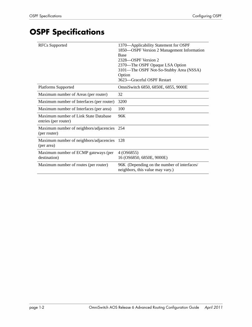
OSPF SpecificationsRFCs Supported 1370—Applicability Statement for OSPF
1850—OSPF Version 2 Management Information Base2328—OSPF Version 22370—The OSPF Opaque LSA Option3101—The OSPF Not-So-Stubby Area (NSSA) Option3623—Graceful OSPF Restart
Platforms Supported OmniSwitch 6850, 6850E, 6855, 9000E
Maximum number of Areas (per router) 32
Maximum number of Interfaces (per router) 3200
Maximum number of Interfaces (per area) 100
Maximum number of Link State Database entries (per router)
96K
Maximum number of neighbors/adjacencies (per router)
254
Maximum number of neighbors/adjacencies (per area)
128
Maximum number of ECMP gateways (per destination)
4 (OS6855)16 (OS6850, 6850E, 9000E)
Maximum number of routes (per router) 96K (Depending on the number of interfaces/neighbors, this value may vary.)
page 1-2 OmniSwitch AOS Release 6 Advanced Routing Configuration Guide April 2011
Configuring OSPF OSPF Defaults Table
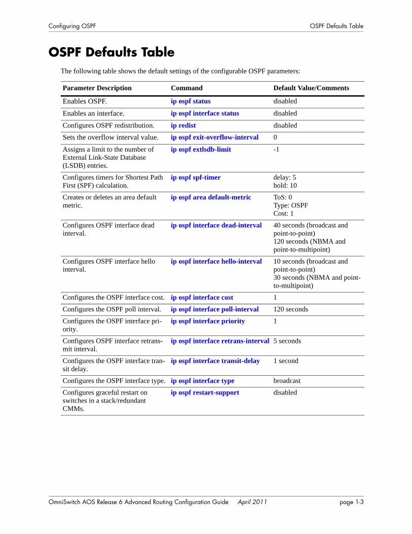
OSPF Defaults TableThe following table shows the default settings of the configurable OSPF parameters:
Parameter Description Command Default Value/Comments
Enables OSPF. ip ospf status disabled
Enables an interface. ip ospf interface status disabled
Configures OSPF redistribution. ip redist disabled
Sets the overflow interval value. ip ospf exit-overflow-interval 0
Assigns a limit to the number of External Link-State Database (LSDB) entries.
ip ospf extlsdb-limit -1
Configures timers for Shortest Path First (SPF) calculation.
ip ospf spf-timer delay: 5hold: 10
Creates or deletes an area default metric.
ip ospf area default-metric ToS: 0Type: OSPFCost: 1
Configures OSPF interface dead interval.
ip ospf interface dead-interval 40 seconds (broadcast and point-to-point)120 seconds (NBMA and point-to-multipoint)
Configures OSPF interface hello interval.
ip ospf interface hello-interval 10 seconds (broadcast and point-to-point)30 seconds (NBMA and point-to-multipoint)
Configures the OSPF interface cost. ip ospf interface cost 1
Configures the OSPF poll interval. ip ospf interface poll-interval 120 seconds
Configures the OSPF interface pri-ority.
ip ospf interface priority 1
Configures OSPF interface retrans-mit interval.
ip ospf interface retrans-interval 5 seconds
Configures the OSPF interface tran-sit delay.
ip ospf interface transit-delay 1 second
Configures the OSPF interface type. ip ospf interface type broadcast
Configures graceful restart on switches in a stack/redundant CMMs.
ip ospf restart-support disabled
OmniSwitch AOS Release 6 Advanced Routing Configuration Guide April 2011 page 1-3
OSPF Quick Steps Configuring OSPF
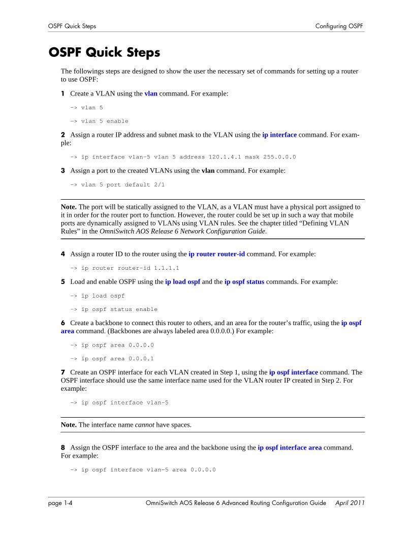
OSPF Quick StepsThe followings steps are designed to show the user the necessary set of commands for setting up a router to use OSPF:
1 Create a VLAN using the vlan command. For example:
-> vlan 5
-> vlan 5 enable
2 Assign a router IP address and subnet mask to the VLAN using the ip interface command. For exam-ple:
-> ip interface vlan-5 vlan 5 address 120.1.4.1 mask 255.0.0.0
3 Assign a port to the created VLANs using the vlan command. For example:
-> vlan 5 port default 2/1
Note. The port will be statically assigned to the VLAN, as a VLAN must have a physical port assigned to it in order for the router port to function. However, the router could be set up in such a way that mobile ports are dynamically assigned to VLANs using VLAN rules. See the chapter titled “Defining VLAN Rules” in the OmniSwitch AOS Release 6 Network Configuration Guide.
4 Assign a router ID to the router using the ip router router-id command. For example:
-> ip router router-id 1.1.1.1
5 Load and enable OSPF using the ip load ospf and the ip ospf status commands. For example:
-> ip load ospf
-> ip ospf status enable
6 Create a backbone to connect this router to others, and an area for the router’s traffic, using the ip ospf area command. (Backbones are always labeled area 0.0.0.0.) For example:
-> ip ospf area 0.0.0.0
-> ip ospf area 0.0.0.1
7 Create an OSPF interface for each VLAN created in Step 1, using the ip ospf interface command. The OSPF interface should use the same interface name used for the VLAN router IP created in Step 2. For example:
-> ip ospf interface vlan-5
Note. The interface name cannot have spaces.
8 Assign the OSPF interface to the area and the backbone using the ip ospf interface area command. For example:
-> ip ospf interface vlan-5 area 0.0.0.0
page 1-4 OmniSwitch AOS Release 6 Advanced Routing Configuration Guide April 2011
Configuring OSPF OSPF Quick Steps
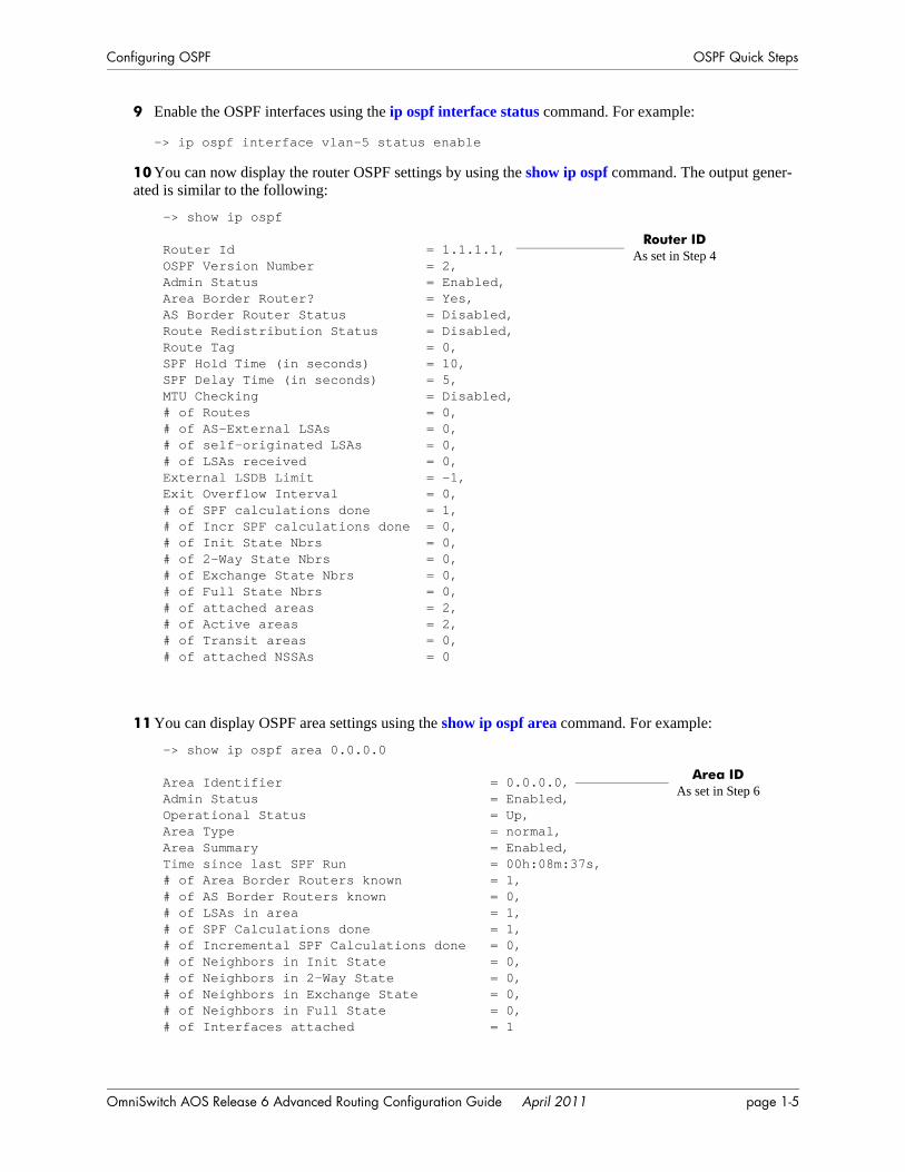
9 Enable the OSPF interfaces using the ip ospf interface status command. For example:
-> ip ospf interface vlan-5 status enable
10 You can now display the router OSPF settings by using the show ip ospf command. The output gener-ated is similar to the following:
11 You can display OSPF area settings using the show ip ospf area command. For example:
-> show ip ospf
Router Id = 1.1.1.1,OSPF Version Number = 2,Admin Status = Enabled,Area Border Router? = Yes,AS Border Router Status = Disabled,Route Redistribution Status = Disabled,Route Tag = 0,SPF Hold Time (in seconds) = 10,SPF Delay Time (in seconds) = 5,MTU Checking = Disabled,# of Routes = 0,# of AS-External LSAs = 0,# of self-originated LSAs = 0,# of LSAs received = 0,External LSDB Limit = -1,Exit Overflow Interval = 0,# of SPF calculations done = 1,# of Incr SPF calculations done = 0,# of Init State Nbrs = 0,# of 2-Way State Nbrs = 0,# of Exchange State Nbrs = 0,# of Full State Nbrs = 0,# of attached areas = 2,# of Active areas = 2,# of Transit areas = 0,# of attached NSSAs = 0
Router IDAs set in Step 4
-> show ip ospf area 0.0.0.0
Area Identifier = 0.0.0.0,Admin Status = Enabled,Operational Status = Up,Area Type = normal,Area Summary = Enabled,Time since last SPF Run = 00h:08m:37s,# of Area Border Routers known = 1,# of AS Border Routers known = 0,# of LSAs in area = 1,# of SPF Calculations done = 1,# of Incremental SPF Calculations done = 0,# of Neighbors in Init State = 0,# of Neighbors in 2-Way State = 0,# of Neighbors in Exchange State = 0,# of Neighbors in Full State = 0, # of Interfaces attached = 1
Area ID As set in Step 6
OmniSwitch AOS Release 6 Advanced Routing Configuration Guide April 2011 page 1-5
OSPF Quick Steps Configuring OSPF
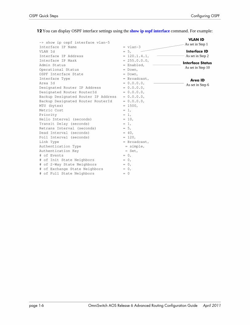
12 You can display OSPF interface settings using the show ip ospf interface command. For example:
-> show ip ospf interface vlan-5Interface IP Name = vlan-3VLAN Id = 5,Interface IP Address = 120.1.4.1,Interface IP Mask = 255.0.0.0,Admin Status = Enabled,Operational Status = Down,OSPF Interface State = Down,Interface Type = Broadcast,Area Id = 0.0.0.0,Designated Router IP Address = 0.0.0.0,Designated Router RouterId = 0.0.0.0,Backup Designated Router IP Address = 0.0.0.0,Backup Designated Router RouterId = 0.0.0.0,MTU (bytes) = 1500,Metric Cost = 1,Priority = 1,Hello Interval (seconds) = 10,Transit Delay (seconds) = 1,Retrans Interval (seconds) = 5,Dead Interval (seconds) = 40,Poll Interval (seconds) = 120,Link Type = Broadcast,Authentication Type = simple,Authentication Key = Set,# of Events = 0,# of Init State Neighbors = 0,# of 2-Way State Neighbors = 0,# of Exchange State Neighbors = 0,# of Full State Neighbors = 0
VLAN ID As set in Step 1
Interface ID As set in Step 2
Interface StatusAs set in Step 10
Area ID As set in Step 6
page 1-6 OmniSwitch AOS Release 6 Advanced Routing Configuration Guide April 2011
Configuring OSPF OSPF Overview
OSPF OverviewOpen Shortest Path First routing (OSPF) is a shortest path first (SPF), or link-state, protocol. OSPF is an interior gateway protocol (IGP) that distributes routing information between routers in a Single Autono-mous System (AS). OSPF chooses the least-cost path as the best path.
Each participating router distributes its local state (i.e., the router’s usable interfaces, local networks, and reachable neighbors) throughout the AS by flooding. In a link-state protocol, each router maintains a data-base describing the entire topology. This database is built from the collected link state advertisements of all routers. Each multi-access network that has at least two attached routers has a designated router and a backup designated router. The designated router floods a link state advertisement for the multi-access network.
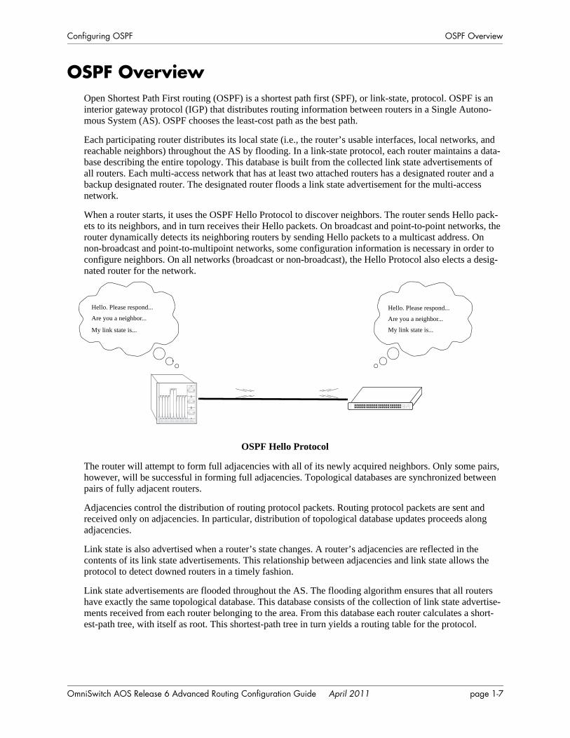
When a router starts, it uses the OSPF Hello Protocol to discover neighbors. The router sends Hello pack-ets to its neighbors, and in turn receives their Hello packets. On broadcast and point-to-point networks, the router dynamically detects its neighboring routers by sending Hello packets to a multicast address. On non-broadcast and point-to-multipoint networks, some configuration information is necessary in order to configure neighbors. On all networks (broadcast or non-broadcast), the Hello Protocol also elects a desig-nated router for the network.
OSPF Hello Protocol
The router will attempt to form full adjacencies with all of its newly acquired neighbors. Only some pairs, however, will be successful in forming full adjacencies. Topological databases are synchronized between pairs of fully adjacent routers.
Adjacencies control the distribution of routing protocol packets. Routing protocol packets are sent and received only on adjacencies. In particular, distribution of topological database updates proceeds along adjacencies.
Link state is also advertised when a router’s state changes. A router’s adjacencies are reflected in the contents of its link state advertisements. This relationship between adjacencies and link state allows the protocol to detect downed routers in a timely fashion.
Link state advertisements are flooded throughout the AS. The flooding algorithm ensures that all routers have exactly the same topological database. This database consists of the collection of link state advertise-ments received from each router belonging to the area. From this database each router calculates a short-est-path tree, with itself as root. This shortest-path tree in turn yields a routing table for the protocol.
Hello. Please respond...
Are you a neighbor...Hello. Please respond...
Are you a neighbor...
My link state is... My link state is...
OmniSwitch AOS Release 6 Advanced Routing Configuration Guide April 2011 page 1-7
OSPF Overview Configuring OSPF
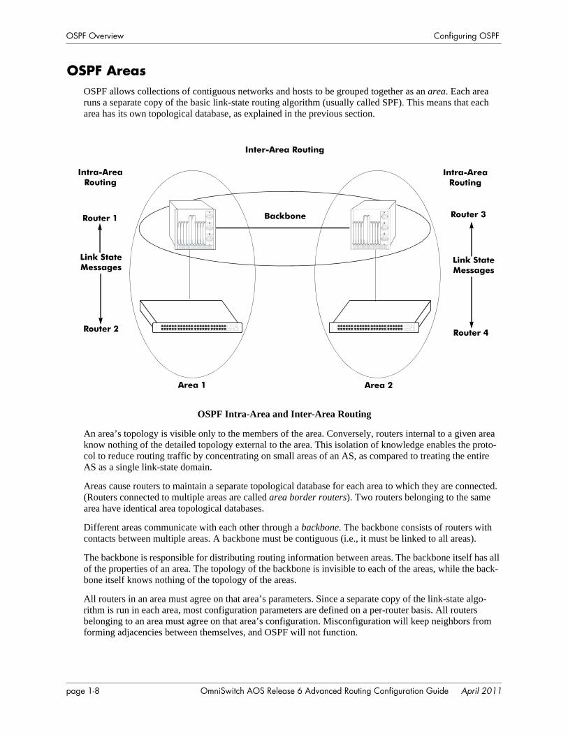
OSPF AreasOSPF allows collections of contiguous networks and hosts to be grouped together as an area. Each area runs a separate copy of the basic link-state routing algorithm (usually called SPF). This means that each area has its own topological database, as explained in the previous section.
OSPF Intra-Area and Inter-Area Routing
An area’s topology is visible only to the members of the area. Conversely, routers internal to a given area know nothing of the detailed topology external to the area. This isolation of knowledge enables the proto-col to reduce routing traffic by concentrating on small areas of an AS, as compared to treating the entire AS as a single link-state domain.
Areas cause routers to maintain a separate topological database for each area to which they are connected. (Routers connected to multiple areas are called area border routers). Two routers belonging to the same area have identical area topological databases.
Different areas communicate with each other through a backbone. The backbone consists of routers with contacts between multiple areas. A backbone must be contiguous (i.e., it must be linked to all areas).
The backbone is responsible for distributing routing information between areas. The backbone itself has all of the properties of an area. The topology of the backbone is invisible to each of the areas, while the back-bone itself knows nothing of the topology of the areas.
All routers in an area must agree on that area’s parameters. Since a separate copy of the link-state algo-rithm is run in each area, most configuration parameters are defined on a per-router basis. All routers belonging to an area must agree on that area’s configuration. Misconfiguration will keep neighbors from forming adjacencies between themselves, and OSPF will not function.
Inter-Area Routing
Backbone
Intra-AreaRouting
Intra-AreaRouting
Router 1
Router 2
Router 3
Router 4
Link State Messages
Link State Messages
Area 1 Area 2
page 1-8 OmniSwitch AOS Release 6 Advanced Routing Configuration Guide April 2011

Configuring OSPF OSPF Overview
Classification of RoutersWhen an AS is split into OSPF areas, the routers are further divided according to function into the follow-ing four overlapping categories:
• Internal routers. A router with all directly connected networks belonging to the same area. These routers run a single copy of the SPF algorithm.
• Area border routers. A router that attaches to multiple areas. Area border routers run multiple copies of the SPF algorithm, one copy for each attached area. Area border routers condense the topological information of their attached areas for flooding to other areas.
• Backbone routers. A router that has an interface to the backbone. This includes all routers that inter-face to more than one area (i.e., area border routers). However, backbone routers do not have to be area border routers. Routers with all interfaces connected to the backbone are considered to be internal rout-ers.
• AS boundary routers. A router that exchanges routing information with routers belonging to other Autonomous Systems. Such a router has AS external routes that are advertised throughout the Autono-mous System. The path to each AS boundary router is known by every router in the AS. This classifi-cation is completely independent of the previous classifications (i.e., internal, area border, and backbone routers). AS boundary routers may be internal or area border routers, and may or may not participate in the backbone.
Virtual LinksIt is possible to define areas in such a way that the backbone is no longer contiguous. (This is not an ideal OSPF configuration, and maximum effort should be made to avoid this situation.) In this case the system administrator must restore backbone connectivity by configuring virtual links.
Virtual links can be configured between any two backbone routers that have a connection to a common non-backbone area. The protocol treats two routers joined by a virtual link as if they were connected by an unnumbered point-to-point network. The routing protocol traffic that flows along the virtual link uses intra-area routing only, and the physical connection between the two routers is not managed by the network administrator (i.e., there is no dedicated connection between the routers as there is with the OSPF backbone).
OSPF Routers Connected with a Virtual Link
In the above diagram, Router A and Router B are connected via a virtual link in Area 1, which is known as a transit area. See “Creating Virtual Links” on page 1-22 for more information.
Router A Router B
Backbone Virtual Link
Area 1
Backbone
OmniSwitch AOS Release 6 Advanced Routing Configuration Guide April 2011 page 1-9

OSPF Overview Configuring OSPF
Stub AreasOSPF allows certain areas to be configured as stub areas. A stub area is an area with routers that have no AS external Link State Advertisements (LSAs).
In order to take advantage of the OSPF stub area support, default routing must be used in the stub area. This is accomplished by configuring only one of the stub area’s border routers to advertise a default route into the stub area. The default routes will match any destination that is not explicitly reachable by an intra-area or inter-area path (i.e., AS external destinations).
OSPF Stub Area
Area 1 and Area 3 could be configured as stub areas. Stub areas are configured using the OSPF ip ospf area command, described in “Creating an Area” on page 1-17. For more overview information on areas, see “OSPF Areas” on page 1-8.
The OSPF protocol ensures that all routers belonging to an area agree on whether the area has been config-ured as a stub. This guarantees that no confusion will arise in the flooding of AS external advertisements.
Two restrictions on the use of stub areas are:
• Virtual links cannot be configured through stub areas.
• AS boundary routers cannot be placed internal to stub areas.
Area 3(stub)
Area 2Area 1(stub)
Backbone
Backbone
page 1-10 OmniSwitch AOS Release 6 Advanced Routing Configuration Guide April 2011
Configuring OSPF OSPF Overview
Not-So-Stubby-AreasNSSA, or not-so-stubby area, is an extension to the base OSPF specification and is defined in RFC 1587. An NSSA is similar to a stub area in many ways: AS-external LSAs are not flooded into an NSSA and virtual links are not allowed in an NSSA. The primary difference is that selected external routing informa-tion can be imported into an NSSA and then redistributed into the rest of the OSPF routing domain. These routes are imported into the NSSA using a new LSA type: Type-7 LSA. Type-7 LSAs are flooded within the NSSA and are translated at the NSSA boundary into AS-external LSAs so as to convey the external routing information to other areas.
NSSAs enable routers with limited resources to participate in OSPF routing while also allowing the import of a selected number of external routes into the area. For example, an area which connects to a small external routing domain running RIP may be configured as an NSSA. This will allow the import of RIP routes into this area and the rest of the OSPF routing domain and at the same time, prevent the flooding of other external routing information (learned, for example, through RIP) into this area.
All routers in an NSSA must have their OSPF area defined as an NSSA. To configure otherwise will ensure that the router will be unsuccessful in establishing an adjacent in the OSPF domain.
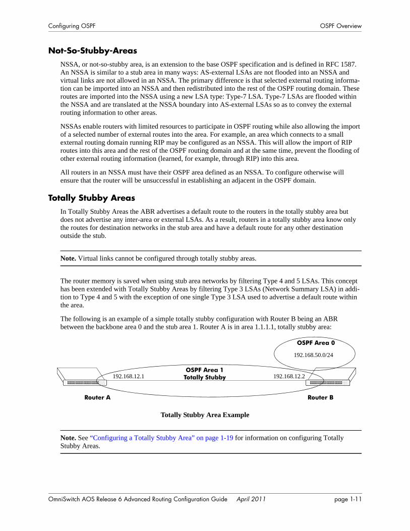
Totally Stubby AreasIn Totally Stubby Areas the ABR advertises a default route to the routers in the totally stubby area but does not advertise any inter-area or external LSAs. As a result, routers in a totally stubby area know only the routes for destination networks in the stub area and have a default route for any other destination outside the stub.
Note. Virtual links cannot be configured through totally stubby areas.
The router memory is saved when using stub area networks by filtering Type 4 and 5 LSAs. This concept has been extended with Totally Stubby Areas by filtering Type 3 LSAs (Network Summary LSA) in addi-tion to Type 4 and 5 with the exception of one single Type 3 LSA used to advertise a default route within the area.
The following is an example of a simple totally stubby configuration with Router B being an ABR between the backbone area 0 and the stub area 1. Router A is in area 1.1.1.1, totally stubby area:
Totally Stubby Area Example
Note. See “Configuring a Totally Stubby Area” on page 1-19 for information on configuring Totally Stubby Areas.
Router A Router B
OSPF Area 0
192.168.12.1OSPF Area 1
Totally Stubby 192.168.12.2
192.168.50.0/24
OmniSwitch AOS Release 6 Advanced Routing Configuration Guide April 2011 page 1-11

OSPF Overview Configuring OSPF
Equal Cost Multi-Path (ECMP) RoutingUsing information from its continuously updated databases, OSPF calculates the shortest path to a given destination. Shortest path is determined from metric values at each hop along a path. At times, two or more paths to the same destination will have the same metric cost.
In the network illustration below, there are two paths from Source router A to Destination router B. One path traverses two hops at routers X and Y and the second path traverses two hops at M and N. If the total cost through X and Y to B is the same as the cost via M and N to B, then these two paths have equal cost. In this version of OSPF both paths will be stored and used to transmit data.
Multiple Equal Cost Paths
Delivery of packets along equal paths is based on flows rather than a round-robin scheme. Equal cost is determined based on standard routing metrics. However, other variables, such as line speed, are not considered. So it is possible for OSPF to decide two paths have an equal cost even though one may contain faster links than another.
Non Broadcast OSPF RoutingOSPF can operate in two modes on non-broadcast networks: NBMA and point-to-multipoint. The inter-face type for the corresponding network segment should be set to non-broadcast or point-to-multipoint, respectively.
For non-broadcast networks neighbors should be statically configured. For NBMA neighbors the eligibil-ity option must be enabled for the neighboring router to participate in Designated Router (DR) election.
For the correct working of an OSPF NBMA network, a fully meshed network is mandatory. Also, the neighbor eligibility configuration for a router on every other router should match the routers interface priority configuration.
See “Configuring Static Neighbors” on page 1-31 for more information and setting up static neighbors.
Source (A) Destination (B)
X Y
M N
A-> X-> Y-> B = A-> M-> N-> B
page 1-12 OmniSwitch AOS Release 6 Advanced Routing Configuration Guide April 2011
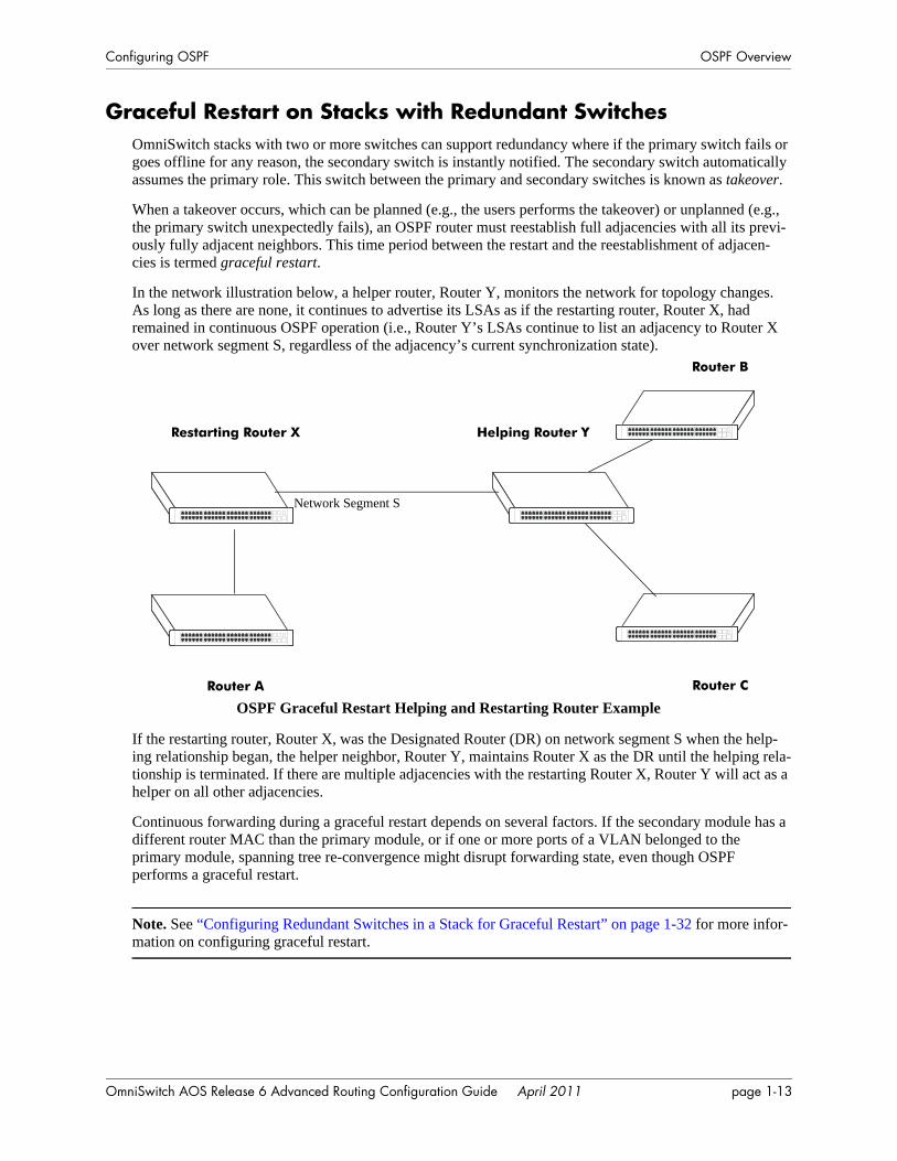
Configuring OSPF OSPF Overview
Graceful Restart on Stacks with Redundant SwitchesOmniSwitch stacks with two or more switches can support redundancy where if the primary switch fails or goes offline for any reason, the secondary switch is instantly notified. The secondary switch automatically assumes the primary role. This switch between the primary and secondary switches is known as takeover.
When a takeover occurs, which can be planned (e.g., the users performs the takeover) or unplanned (e.g., the primary switch unexpectedly fails), an OSPF router must reestablish full adjacencies with all its previ-ously fully adjacent neighbors. This time period between the restart and the reestablishment of adjacen-cies is termed graceful restart.
In the network illustration below, a helper router, Router Y, monitors the network for topology changes. As long as there are none, it continues to advertise its LSAs as if the restarting router, Router X, had remained in continuous OSPF operation (i.e., Router Y’s LSAs continue to list an adjacency to Router X over network segment S, regardless of the adjacency’s current synchronization state).
OSPF Graceful Restart Helping and Restarting Router Example
If the restarting router, Router X, was the Designated Router (DR) on network segment S when the help-ing relationship began, the helper neighbor, Router Y, maintains Router X as the DR until the helping rela-tionship is terminated. If there are multiple adjacencies with the restarting Router X, Router Y will act as a helper on all other adjacencies.
Continuous forwarding during a graceful restart depends on several factors. If the secondary module has a different router MAC than the primary module, or if one or more ports of a VLAN belonged to the primary module, spanning tree re-convergence might disrupt forwarding state, even though OSPF performs a graceful restart.
Note. See “Configuring Redundant Switches in a Stack for Graceful Restart” on page 1-32 for more infor-mation on configuring graceful restart.
Restarting Router X
Network Segment S
Helping Router Y
Router A
Router B
Router C
OmniSwitch AOS Release 6 Advanced Routing Configuration Guide April 2011 page 1-13
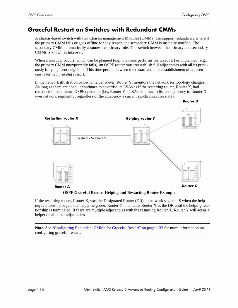
OSPF Overview Configuring OSPF
Graceful Restart on Switches with Redundant CMMsA chassis-based switch with two Chassis management Modules (CMMs) can support redundancy where if the primary CMM fails or goes offline for any reason, the secondary CMM is instantly notified. The secondary CMM automatically assumes the primary role. This switch between the primary and secondary CMMs is known as takeover.
When a takeover occurs, which can be planned (e.g., the users performs the takeover) or unplanned (e.g., the primary CMM unexpectedly fails), an OSPF router must reestablish full adjacencies with all its previ-ously fully adjacent neighbors. This time period between the restart and the reestablishment of adjacen-cies is termed graceful restart.
In the network illustration below, a helper router, Router Y, monitors the network for topology changes. As long as there are none, it continues to advertise its LSAs as if the restarting router, Router X, had remained in continuous OSPF operation (i.e., Router Y’s LSAs continue to list an adjacency to Router X over network segment S, regardless of the adjacency’s current synchronization state).
OSPF Graceful Restart Helping and Restarting Router Example
If the restarting router, Router X, was the Designated Router (DR) on network segment S when the help-ing relationship began, the helper neighbor, Router Y, maintains Router X as the DR until the helping rela-tionship is terminated. If there are multiple adjacencies with the restarting Router X, Router Y will act as a helper on all other adjacencies.
Note. See “Configuring Redundant CMMs for Graceful Restart” on page 1-33 for more information on configuring graceful restart.
Network Segment S
Restarting router X
Router A
Helping router Y
Router B
Router C
page 1-14 OmniSwitch AOS Release 6 Advanced Routing Configuration Guide April 2011
Configuring OSPF Configuring OSPF
Configuring OSPFConfiguring OSPF on a router requires several steps. Depending on your requirements, you may not need to perform all of the steps listed below.
By default, OSPF is disabled on the router. Configuring OSPF consists of these tasks:
• Set up the basics of the OSPF network by configuring the required VLANs, assigning ports to the VLANs, and assigning router identification numbers to the routers involved. This is described in “Preparing the Network for OSPF” on page 1-16.
• Enable OSPF. When the image file for advanced routing is installed, you must load the code and enable OSPF. The commands for enabling OSPF are described in “Activating OSPF” on page 1-16.
• Create an OSPF area and the backbone. The commands to create areas and backbones are described in “Creating an OSPF Area” on page 1-17.
• Set area parameters (optional). OSPF will run with the default area parameters, but different networks may benefit from modifying the parameters. Modifying area parameters is described in “Configuring Stub Area Default Metrics” on page 1-19.
• Create OSPF interfaces. OSPF interfaces are created and assigned to areas. Creating interfaces is described in “Creating an Interface” on page 1-20, and assigning interfaces is described in “Assigning an Interface to an Area” on page 1-20.
• Set interface parameters (optional). OSPF will run with the default interface parameters, but different networks may benefit from modifying the parameters. Also, it is possible to set authentication on an interface. Setting interface authentication is described in “Interface Authentication” on page 1-21, and modifying interface parameters is described in “Modifying Interface Parameters” on page 1-22.
• Configure virtual links (optional). A virtual link is used to establish backbone connectivity when two backbone routers are not physically contiguous. To create a virtual link, see “Creating Virtual Links” on page 1-22.
• Create a redistribution policy and enable the same using route maps (optional). To create route maps, see “Configuring Redistribution” on page 1-23.
• Configure router capabilities (optional). There are several commands that influence router operation. These are covered briefly in a table in “Configuring Router Capabilities” on page 1-30.
• Create static neighbors (optional). These commands allow you to statically configure neighbors. See “Configuring Static Neighbors” on page 1-31.
• Configure redundant switches for graceful OSPF restart (optional). Configuring switches with redun-dant switches for graceful restart is described in “Configuring Redundant Switches in a Stack for Graceful Restart” on page 1-32.
• Configure redundant CMMs for graceful OSPF restart (optional). Configuring switches with redun-dant switches for graceful restart is described in “Configuring Redundant CMMs for Graceful Restart” on page 1-33.
At the end of the chapter is a simple OSPF network diagram with instructions on how it was created on a router-by-router basis. See “OSPF Application Example” on page 1-34 for more information.
OmniSwitch AOS Release 6 Advanced Routing Configuration Guide April 2011 page 1-15
Configuring OSPF Configuring OSPF
Preparing the Network for OSPFOSPF operates on top of normal switch functions, using existing ports, virtual ports, VLANs, etc. The following network components should already be configured:
• Configure VLANs that are to be used in the OSPF network. VLANS should be created for both the backbone interfaces and all other connected devices that will participate in the OSPF network. A VLAN should exist for each instance in which the backbone connects two routers. VLAN configura-tion is described in “Configuring VLANs” in the OmniSwitch AOS Release 6 Network Configuration Guide.
• Assign IP interfaces to the VLANs. IP interfaces, or router ports, must be assigned to the VLAN. Assigning IP interfaces is described in “Configuring IP” in the OmniSwitch AOS Release 6 Network Configuration Guide.
• Assign ports to the VLANs. The physical ports participating in the OSPF network must be assigned to the created VLANs. Assigning ports to a VLAN is described in “Assigning Ports to VLANs” in the OmniSwitch AOS Release 6 Network Configuration Guide.
• Set the router identification number. (optional) The routers participating in the OSPF network must be assigned a router identification number. This number can be any number, as long as it is in standard dotted decimal format (e.g., 1.1.1.1). Router identification number assignment is discussed in “Config-uring IP” in the OmniSwitch AOS Release 6 Network Configuration Guide. If this is not done, the router identification number is automatically the primary interface address.
Activating OSPFTo run OSPF on the router, the advanced routing image must be installed. For information on how to install image files, see the OmniSwitch AOS Release 6 Switch Management Guide.
After the image file has been installed onto the router, you will need to load the OSPF software into memory and enable it, as described below.
Loading the Software
To load the OSPF software into the router’s running configuration, enter the ip load ospf command at the system prompt:
-> ip load ospf
The OPSF software is now loaded into memory, and can be enabled.
Enabling OSPF
Once the OSPF software has been loaded into the router’s running configuration (either through the CLI or on startup), it must be enabled. To enable OSPF on a router, enter the ip ospf status command at the CLI prompt, as shown:
-> ip ospf status enable
Once OSPF is enabled, you can begin to set up OSPF parameters. To disable OSPF, enter the following:
-> ip ospf status disable
page 1-16 OmniSwitch AOS Release 6 Advanced Routing Configuration Guide April 2011
Configuring OSPF Configuring OSPF
Removing OSPF from Memory
To remove OSPF from the router memory, it is necessary to manually edit the boot.cfg file. The boot.cfg file is an ASCII text-based file that controls many of the switch parameters. Open the file and delete all references to OSPF.
For the operation to take effect the switch needs to be rebooted.
Creating an OSPF AreaOSPF allows a set of network devices in an AS system to be grouped together in areas.
There can be more than one router in an area. Likewise, there can be more than one area on a single router (in effect, making the router the Area Border Router (ABR) for the areas involved), but standard network-ing design does not recommended that more than three areas be handled on a single router.
Areas are named using 32-bit dotted decimal format (e.g., 1.1.1.1). Area 0.0.0.0 is reserved for the back-bone.
Creating an Area
To create an area and associate it with a router, enter the ip ospf area command with the area identifica-tion number at the CLI prompt, as shown:
-> ip ospf area 1.1.1.1
Area 1.1.1.1 will now be created on the router with the default parameters.
The backbone is always area 0.0.0.0. To create this area on a router, you would use the above command, but specify the backbone, as shown:
-> ip ospf area 0.0.0.0
The backbone would now be attached to the router, making it an Area Border Router (ABR).
Specifying an Area Type
When creating areas, an area type can be specified (normal, stub, or NSSA). Area types are described above in “OSPF Areas” on page 1-8. To specify an area type, use the ip ospf area command as shown:
-> ip ospf area 1.1.1.1 type stub
Note. By default, an area is a normal area. The type keyword would be used to change a stub or NSSA area into a normal area.
OmniSwitch AOS Release 6 Advanced Routing Configuration Guide April 2011 page 1-17
Configuring OSPF Configuring OSPF
Enabling and Disabling Summarization
Summarization can also be enabled or disabled when creating an area. Enabling summarization allows for ranges to be used by Area Border Routers (ABRs) for advertising routes as a single route rather than multiple routes, while disabling summarization prevents set ranges from functioning in stub and NSSA areas. (Configuring ranges is described in “Setting Area Ranges” on page 1-19.)
For example, to enable summarization for Area 1.1.1.1, enter the following:
-> ip ospf area 1.1.1.1 summary enable
To disable summarization for the same area, enter the following:
-> ip ospf area 1.1.1.1 summary disable
Note. By default, an area has summarization enabled. Disabling summarization for an area is useful when ranges need to be deactivated, but not deleted.
Displaying Area Status
You can check the status of the newly created area by using the show command, as demonstrated:
-> show ip ospf area 1.1.1.1
or
-> show ip ospf area
The first example gives specifics about area 1.1.1.1, and the second example shows all areas configured on the router.
To display a stub area’s parameters, use the show ip ospf area stub command as follows:
-> show ip ospf area 1.1.1.1 stub
Deleting an Area
To delete an area, enter the ip ospf area command as shown:
-> no ip ospf area 1.1.1.1
page 1-18 OmniSwitch AOS Release 6 Advanced Routing Configuration Guide April 2011

Configuring OSPF Configuring OSPF
Configuring Stub Area Default MetricsThe default metric configures the type of cost metric that a default area border router (ABR) will adver-tise in the default summary Link State Advertisement (LSA). Use the ip ospf area default-metric command to create or delete a default metric for stub or Not So Stubby Area (NSSA) area. Specify the stub area and select a cost value or a route type, as shown:
-> ip ospf area 1.1.1.1 default-metric 0 cost 50
or
-> ip ospf area 1.1.1.1 default-metric 0 type type1
A route has a preset metric associated to it depending on its type. The first example, the stub area is given a default metric of 0 (this is Type of Service 0) and a cost of 50 added to routes from the area. The second example specifies that the cost associated with Type 1 routes should be applied to routes from the area.
Note. At this time, only the default metric of ToS 0 is supported.
To remove the area default-metric setting, enter the ip ospf area default-metric command using the no command, as shown:
-> no ip ospf area 1.1.1.1 default-metric 0
Setting Area Ranges
Area ranges are used to summarize many area routes into a single advertisement at an area boundary. Ranges are advertised as summaries or NSSAs. Ranges also act as filters that either allow the summary to be advertised or not. Ranges are created using the ip ospf area range command. An area and the summary IP address and IP mask must be specified. For example, to create a summary range with IP address 192.5.40.1 and an IP mask of 255.255.255.0 for area 1.1.1.1, the following commands would be entered at the CLI prompt:
-> ip ospf area 1.1.1.1 range summary 192.5.40.1 255.255.255.0
-> ip ospf area 1.1.1.1 range summary 192.5.40.1 255.255.255.0 effect noMatching
To view the configured ranges for an area, use the show ip ospf area range command as demonstrated:
-> show ip ospf area 1.1.1.1 range
Configuring a Totally Stubby Area
In order to configure a totally stubby area you need to configure the area as stub on the ABR and disable summarization. By doing so the ABR will generate a default route in the totally stubby area. In addition, the other routers within the totally stubby area must only have their area configured as stub.
For example, to configure the simple totally stubby configuration shown in the figure in “Configuring a Totally Stubby Area” on page 1-19 where Router B is an ABR between the backbone area 0 and the stub area 1 and Router A is in Totally Stubby Area 1.1.1.1 follow the steps below:
1 Enter the following commands on Router B:
-> ip load ospf-> ip ospf area 0.0.0.0-> ip ospf area 1.1.1.1-> ip ospf area 1.1.1.1 type stub
OmniSwitch AOS Release 6 Advanced Routing Configuration Guide April 2011 page 1-19
Configuring OSPF Configuring OSPF
-> ip ospf area 1.1.1.1 summary disable-> ip ospf area 1.1.1.1 default-metric 0-> ip ospf interface vlan-5-> ip ospf interface vlan-5 area 1.1.1.1-> ip ospf interface vlan-5 status enable-> ip ospf interface vlan-6-> ip ospf interface vlan-6 area 0.0.0.0-> ip ospf interface vlan-6 status enable-> ip ospf status enable
2 Enter the following on Router A:
-> ip load ospf-> ip ospf area 1.1.1.1-> ip ospf area 1.1.1.1 type stub-> ip ospf interface vlan-3-> ip ospf interface vlan-3 area 1.1.1.1-> ip ospf interface vlan-3 status enable-> ip ospf status enable
Creating OSPF InterfacesOnce areas have been established, interfaces need to be created and assigned to the areas.
Creating an Interface
To create an interface, enter the ip ospf interface command with an interface name, as shown:
-> ip ospf interface vlan-213
Note. The interface name cannot have spaces.
The interface can be deleted the by using the no keyword, as shown:
-> no ip ospf interface vlan-213
Assigning an Interface to an Area
Once an interface is created, it must be assigned to an area. (Creating areas is described in “Creating an Area” on page 1-17 above.)
To assign an interface to an area, enter the ip ospf interface area command with the interface name and area identification number at the CLI prompt. For example to add interface vlan-213 to area 1.1.1.1, enter the following:
-> ip ospf interface vlan-213 area 1.1.1.1
An interface can be removed from an area by reassigning it to a new area.
Once an interface has been created and enabled, you can check its status and configuration by using the show ip ospf interface command, as demonstrated:
-> show ip ospf interface vlan-213
Instructions for configuring authentication are given in “Interface Authentication” on page 1-21, and inter-face parameter options are described in “Modifying Interface Parameters” on page 1-22.
page 1-20 OmniSwitch AOS Release 6 Advanced Routing Configuration Guide April 2011
Configuring OSPF Configuring OSPF
Activating an Interface
Once the interface is created and assigned to an area, it must be activated using the ip ospf interface status command with the interface name, as shown:
-> ip ospf interface vlan-213 status enable
The interface can be disabled using the disable keyword in place of the enable keyword.
Interface AuthenticationOSPF allows for the use of authentication on configured interfaces. When authentication is enabled, only neighbors using the same type of authentication and the matching passwords or keys can communicate.
There are two types of authentication: simple and MD5. Simple authentication requires only a text string as a password, while MD5 is a form of encrypted authentication that requires a key and a password. Both types of authentication require the use of more than one command.
Simple Authentication
To enable simple authentication on an interface, enter the ip ospf interface auth-type command with the interface name, as shown:
-> ip ospf interface vlan-213 auth-type simple
Once simple authentication is enabled, the password must be set with the ip ospf interface auth-key command, as shown:
-> ip ospf interface vlan-213 auth-key test
In the above instance, only other interfaces with simple authentication and a password of “test” will be able to use the configured interface.
MD5 Encryption
To configure the same interface for MD5 encryption, enter the ip ospf interface auth-type as shown:
-> ip ospf interface vlan-213 auth-type md5
Once MD5 authentication is set, a key identification and key string must be set with the ip ospf interface md5 key command. For example to set interface 120.5.80.1 to use MD5 authentication with a key identifi-cation of 7 and key string of “test”, enter:
-> ip ospf interface vlan-213 md5 7
and
-> ip ospf interface vlan-213 md5 7 key "test"
Note that setting the key ID and key string must be done in two separate commands. Once the key ID and key string have been set, MD5 authentication is enabled. To disable it, use the ip ospf interface md5 command, as shown:
-> ip ospf interface vlan-213 md5 7 disable
To remove all authentication, enter the ip ospf interface auth-type as follows:
-> ip ospf interface vlan-213 auth-type none
OmniSwitch AOS Release 6 Advanced Routing Configuration Guide April 2011 page 1-21
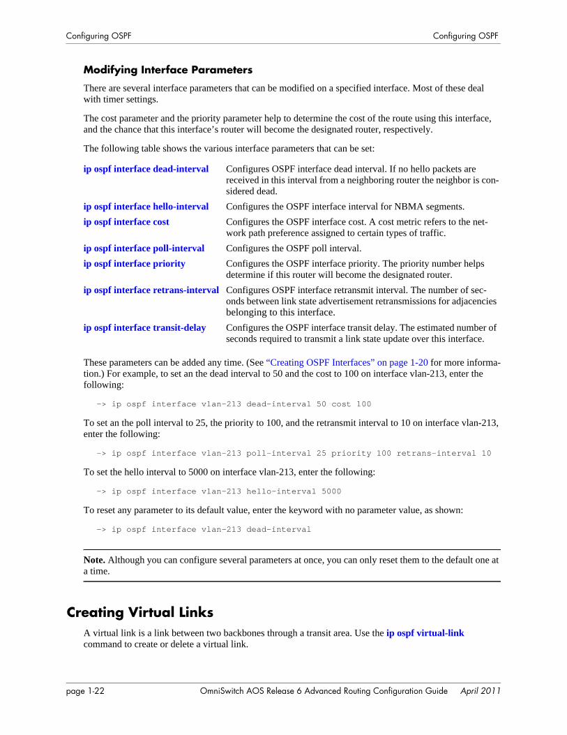
Configuring OSPF Configuring OSPF
Modifying Interface Parameters
There are several interface parameters that can be modified on a specified interface. Most of these deal with timer settings.
The cost parameter and the priority parameter help to determine the cost of the route using this interface, and the chance that this interface’s router will become the designated router, respectively.
The following table shows the various interface parameters that can be set:
These parameters can be added any time. (See “Creating OSPF Interfaces” on page 1-20 for more informa-tion.) For example, to set an the dead interval to 50 and the cost to 100 on interface vlan-213, enter the following:
-> ip ospf interface vlan-213 dead-interval 50 cost 100
To set an the poll interval to 25, the priority to 100, and the retransmit interval to 10 on interface vlan-213, enter the following:
-> ip ospf interface vlan-213 poll-interval 25 priority 100 retrans-interval 10
To set the hello interval to 5000 on interface vlan-213, enter the following:
-> ip ospf interface vlan-213 hello-interval 5000
To reset any parameter to its default value, enter the keyword with no parameter value, as shown:
-> ip ospf interface vlan-213 dead-interval
Note. Although you can configure several parameters at once, you can only reset them to the default one at a time.
Creating Virtual LinksA virtual link is a link between two backbones through a transit area. Use the ip ospf virtual-link command to create or delete a virtual link.
ip ospf interface dead-interval Configures OSPF interface dead interval. If no hello packets are received in this interval from a neighboring router the neighbor is con-sidered dead.
ip ospf interface hello-interval Configures the OSPF interface interval for NBMA segments.ip ospf interface cost Configures the OSPF interface cost. A cost metric refers to the net-
work path preference assigned to certain types of traffic.ip ospf interface poll-interval Configures the OSPF poll interval.ip ospf interface priority Configures the OSPF interface priority. The priority number helps
determine if this router will become the designated router.ip ospf interface retrans-interval Configures OSPF interface retransmit interval. The number of sec-
onds between link state advertisement retransmissions for adjacencies belonging to this interface.
ip ospf interface transit-delay Configures the OSPF interface transit delay. The estimated number of seconds required to transmit a link state update over this interface.
page 1-22 OmniSwitch AOS Release 6 Advanced Routing Configuration Guide April 2011
Configuring OSPF Configuring OSPF
Accepted network design theory states that virtual links are the option of last resort. For more information on virtual links, see “Virtual Links” on page 1-9 and refer to the figure on page 1-9.
Creating a Virtual Link
To create a virtual link, commands must be submitted to the routers at both ends of the link. The router being configured should point to the other end of the link, and both routers must have a common area.
When entering the ip ospf virtual-link command, it is necessary to enter the Router ID of the far end of the link, and the area ID that both ends of the link share.
For example, a virtual link needs to be created between Router A (router ID 1.1.1.1) and Router B (router ID 2.2.2.2). We must:
1 Establish a transit area between the two routers using the commands discussed in “Creating an OSPF Area” on page 1-17 (in this example, we will use Area 0.0.0.1).
2 Then use the ip ospf virtual-link command on Router A as shown:
-> ip ospf virtual-link 0.0.0.1 2.2.2.2
3 Next, enter the following command on Router B:
-> ip ospf virtual-link 0.0.0.1 1.1.1.1
Now there is a virtual link across Area 0.0.0.1 linking Router A and Router B.
4 To display virtual links configured on a router, enter the following show command:
-> show ip ospf virtual-link
5 To delete a virtual link, enter the ip ospf virtual-link command with the area and far end router infor-mation, as shown:
-> no ip ospf virtual-link 0.0.0.1 2.2.2.2
Modifying Virtual Link Parameters
There are several parameters for a virtual link (such as authentication type and cost) that can be modified at the time of the link creation. They are described in the ip ospf virtual-link command description. These parameters are identical in function to their counterparts in the section “Modifying Interface Parameters” on page 1-22.
Configuring RedistributionIt is possible to learn and advertise IPv4 routes between different protocols. Such a process is referred to as route redistribution and is configured using the ip redist command.
Redistribution uses route maps to control how external routes are learned and distributed. A route map consists of one or more user-defined statements that can determine which routes are allowed or denied access to the network. In addition a route map may also contain statements that modify route parameters before they are redistributed.
When a route map is created, it is given a name to identify the group of statements that it represents. This name is required by the ip redist command. Therefore, configuring route redistribution involves the following steps:
OmniSwitch AOS Release 6 Advanced Routing Configuration Guide April 2011 page 1-23
Configuring OSPF Configuring OSPF
1 Create a route map, as described in “Using Route Maps” on page 1-24.
2 Configure redistribution to apply a route map, as described in “Configuring Route Map Redistribu-tion” on page 1-27.
Note. An OSPF router automatically becomes an Autonomous System Border Router (ASBR) when redis-tribution is configured on the router.
Using Route MapsA route map specifies the criteria that are used to control redistribution of routes between protocols. Such criteria is defined by configuring route map statements. There are three different types of statements:
• Action. An action statement configures the route map name, sequence number, and whether or not redistribution is permitted or denied based on route map criteria.
• Match. A match statement specifies criteria that a route must match. When a match occurs, then the action statement is applied to the route.
• Set. A set statement is used to modify route information before the route is redistributed into the receiving protocol. This statement is only applied if all the criteria of the route map is met and the action permits redistribution.
The ip route-map command is used to configure route map statements and provides the following action, match, and set parameters:
Refer to the “IP Commands” chapter in the OmniSwitch CLI Reference Guide for more information about the ip route-map command parameters and usage guidelines.
Once a route map is created, it is then applied using the ip redist command. See “Configuring Route Map Redistribution” on page 1-27 for more information.
Creating a Route Map
When a route map is created, it is given a name (up to 20 characters), a sequence number, and an action (permit or deny). Specifying a sequence number is optional. If a value is not configured, then the number 50 is used by default.
To create a route map, use the ip route-map command with the action parameter. For example,
-> ip route-map ospf-to-bgp sequence-number 10 action permit
The above command creates the ospf-to-bgp route map, assigns a sequence number of 10 to the route map, and specifies a permit action.
ip route-map action ... ip route-map match ... ip route-map set ...
permitdeny
ip-addressip-nexthopipv6-addressipv6-nexthoptagipv4-interfaceipv6-interfacemetricroute-type
metricmetric-typetagcommunitylocal-preferencelevelip-nexthopipv6-nexthop
page 1-24 OmniSwitch AOS Release 6 Advanced Routing Configuration Guide April 2011
Configuring OSPF Configuring OSPF
To optionally filter routes before redistribution, use the ip route-map command with a match parameter to configure match criteria for incoming routes. For example,
-> ip route-map ospf-to-bgp sequence-number 10 match tag 8
The above command configures a match statement for the ospf-to-bgp route map to filter routes based on their tag value. When this route map is applied, only OSPF routes with a tag value of eight are redistrib-uted into the BGP network. All other routes with a different tag value are dropped.
Note. Configuring match statements is not required. However, if a route map does not contain any match statements and the route map is applied using the ip redist command, the router redistributes all routes into the network of the receiving protocol.
To modify route information before it is redistributed, use the ip route-map command with a set parame-ter. For example,
-> ip route-map ospf-to-bgp sequence-number 10 set tag 5
The above command configures a set statement for the ospf-to-bgp route map that changes the route tag value to five. Because this statement is part of the ospf-to-bgp route map, it is only applied to routes that have an existing tag value equal to eight.
The following is a summary of the commands used in the above examples:
-> ip route-map ospf-to-bgp sequence-number 10 action permit-> ip route-map ospf-to-bgp sequence-number 10 match tag 8-> ip route-map ospf-to-bgp sequence-number 10 set tag 5
To verify a route map configuration, use the show ip route-map command:
-> show ip route-mapRoute Maps: configured: 1 max: 200Route Map: ospf-to-bgp Sequence Number: 10 Action permit match tag 8 set tag 5
Deleting a Route Map
Use the no form of the ip route-map command to delete an entire route map, a route map sequence, or a specific statement within a sequence.
To delete an entire route map, enter no ip route-map followed by the route map name. For example, the following command deletes the entire route map named redistipv4:
-> no ip route-map redistipv4
To delete a specific sequence number within a route map, enter no ip route-map followed by the route map name, then sequence-number followed by the actual number. For example, the following command deletes sequence 10 from the redistipv4 route map:
-> no ip route-map redistipv4 sequence-number 10
Note that in the above example, the redistripv4 route map is not deleted. Only those statements associated with sequence 10 are removed from the route map.
OmniSwitch AOS Release 6 Advanced Routing Configuration Guide April 2011 page 1-25
Configuring OSPF Configuring OSPF
To delete a specific statement within a route map, enter no ip route-map followed by the route map name, then sequence-number followed by the sequence number for the statement, then either match or set and the match or set parameter and value. For example, the following command deletes only the match tag 8 statement from route map redistipv4 sequence 10:
-> no ip route-map redistipv4 sequence-number 10 match tag 8
Configuring Route Map Sequences
A route map may consist of one or more sequences of statements. The sequence number determines which statements belong to which sequence and the order in which sequences for the same route map are processed.
To add match and set statements to an existing route map sequence, specify the same route map name and sequence number for each statement. For example, the following series of commands creates route map rm_1 and configures match and set statements for the rm_1 sequence 10:
-> ip route-map rm_1 sequence-number 10 action permit-> ip route-map rm_1 sequence-number 10 match tag 8-> ip route-map rm_1 sequence-number 10 set metric 1
To configure a new sequence of statements for an existing route map, specify the same route map name but use a different sequence number. For example, the following command creates a new sequence 20 for the rm_1 route map:
-> ip route-map rm_1 sequence-number 20 action permit-> ip route-map rm_1 sequence-number 20 match ipv4-interface to-finance-> ip route-map rm_1 sequence-number 20 set metric 5
The resulting route map appears as follows:
-> show ip route-map rm_1Route Map: rm_1 Sequence Number: 10 Action permit match tag 8 set metric 1Route Map: rm_1 Sequence Number: 20 Action permit match ip6 interface to-finance set metric 5
Sequence 10 and sequence 20 are both linked to route map rm_1 and are processed in ascending order according to their sequence number value. Note that there is an implied logical OR between sequences. As a result, if there is no match for the tag value in sequence 10, then the match interface statement in sequence 20 is processed. However, if a route matches the tag 8 value, then sequence 20 is not used. The set statement for whichever sequence was matched is applied.
A route map sequence may contain multiple match statements. If these statements are of the same kind (e.g., match tag 5, match tag 8, etc.) then a logical OR is implied between each like statement. If the match statements specify different types of matches (e.g. match tag 5, match ip4 interface to-finance, etc.), then a logical AND is implied between each statement. For example, the following route map sequence will redistribute a route if its tag is either 8 or 5:
-> ip route-map rm_1 sequence-number 10 action permit-> ip route-map rm_1 sequence-number 10 match tag 5-> ip route-map rm_1 sequence-number 10 match tag 8
The following route map sequence will redistribute a route if the route has a tag of 8 or 5 and the route was learned on the IPv4 interface to-finance:
-> ip route-map rm_1 sequence-number 10 action permit
page 1-26 OmniSwitch AOS Release 6 Advanced Routing Configuration Guide April 2011

Configuring OSPF Configuring OSPF
-> ip route-map rm_1 sequence-number 10 match tag 5-> ip route-map rm_1 sequence-number 10 match tag 8-> ip route-map rm_1 sequence-number 10 match ipv4-interface to-finance
Configuring Access Lists
An IP access list provides a convenient way to add multiple IPv4 or IPv6 addresses to a route map. Using an access list avoids having to enter a separate route map statement for each individual IP address. Instead, a single statement is used that specifies the access list name. The route map is then applied to all the addresses contained within the access list.
Configuring an IP access list involves two steps: creating the access list and adding IP addresses to the list. To create an IP access list, use the ip access-list command (IPv4) or the ipv6 access-list command (IPv6) and specify a name to associate with the list. For example,
-> ip access-list ipaddr-> ipv6 access-list ip6addr
To add addresses to an access list, use the ip access-list address (IPv4) or the ipv6 access-list address (IPv6) command. For example, the following commands add addresses to an existing access list:
-> ip access-list ipaddr address 16.24.2.1/16-> ipv6 access-list ip6addr address 2001::1/64
Use the same access list name each time the above commands are used to add additional addresses to the same access list. In addition, both commands provide the ability to configure if an address and/or its matching subnet routes are permitted (the default) or denied redistribution. For example:
-> ip access-list ipaddr address 16.24.2.1/16 action deny redist-control all-subnets-> ipv6 access-list ip6addr address 2001::1/64 action permit redist-control no-subnets
For more information about configuring access list commands, see the “IP Commands” chapter in the OmniSwitch CLI Reference Guide.
Configuring Route Map RedistributionThe ip redist command is used to configure the redistribution of routes from a source protocol into the destination protocol. This command is used on the router that will perform the redistribution.
Note. An OSPF router automatically becomes an Autonomous System Border Router (ASBR) when redis-tribution is configured on the router.
A source protocol is a protocol from which the routes are learned. A destination protocol is the one into which the routes are redistributed. Make sure that both protocols are loaded and enabled before configur-ing redistribution.
Redistribution applies criteria specified in a route map to routes received from the source protocol. There-fore, configuring redistribution requires an existing route map. For example, the following command configures the redistribution of OSPF routes into the BGP network using the ospf-to-bgp route map:
-> ip redist ospf into bgp route-map ospf-to-bgp
OSPF routes received by the router interface are processed based on the contents of the ospf-to-bgp route map. Routes that match criteria specified in this route map are either allowed or denied redistribution into
OmniSwitch AOS Release 6 Advanced Routing Configuration Guide April 2011 page 1-27
Configuring OSPF Configuring OSPF
the BGP network. The route map may also specify the modification of route information before the route is redistributed. See “Using Route Maps” on page 1-24 for more information.
To remove a route map redistribution configuration, use the no form of the ip redist command. For exam-ple:
-> no ip ospf into bgp route-map ospf-to-bgp
Use the show ip redist command to verify the redistribution configuration:
-> show ip redist
Source DestinationProtocol Protocol Status Route Map------------+------------+---------+--------------------LOCAL4 RIP Enabled rip_1LOCAL4 OSPF Enabled ospf_2LOCAL4 BGP Enabled bgp_3BGP OSPF Enabled ospf-to-bgp
Configuring the Administrative Status of the Route Map Redistribution
The administrative status of a route map redistribution configuration is enabled by default. To change the administrative status, use the status parameter with the ip redist command. For example, the following command disables the redistribution administrative status for the specified route map:
-> ip redist ospf into bgp route-map ospf-to-bgp status disable
The following command example enables the administrative status:
-> ip redist ospf into bgp route-map ospf-to-bgp status enable
page 1-28 OmniSwitch AOS Release 6 Advanced Routing Configuration Guide April 2011
Configuring OSPF Configuring OSPF
Route Map Redistribution ExampleThe following example configures the redistribution of OSPF routes into a BGP network using a route map (ospf-to-bgp) to filter specific routes:
-> ip route-map ospf-to-bgp sequence-number 10 action deny -> ip route-map ospf-to-bgp sequence-number 10 match tag 5-> ip route-map ospf-to-bgp sequence-number 10 match route-type external type2
-> ip route-map ospf-to-bgp sequence-number 20 action permit-> ip route-map ospf-to-bgp sequence-number 20 match ipv4-interface intf_ospf-> ip route-map ospf-to-bgp sequence-number 20 set metric 255
-> ip route-map ospf-to-bgp sequence-number 30 action permit-> ip route-map ospf-to-bgp sequence-number 30 set tag 8
-> ip redist ospf into bgp route-map ospf-to-bgp
The resulting ospf-to-bgp route map redistribution configuration does the following:
• Denies the redistribution of Type 2 external OSPF routes with a tag set to five.
• Redistributes into BGP all routes learned on the intf_ospf interface and sets the metric for such routes to 255.
• Redistributes into BGP all other routes (those not processed by sequence 10 or 20) and sets the tag for such routes to eight.
OmniSwitch AOS Release 6 Advanced Routing Configuration Guide April 2011 page 1-29

Configuring OSPF Configuring OSPF
Configuring Router CapabilitiesThe following list shows various commands that can be useful in tailoring a router’s performance capabili-ties. All of the listed parameters have defaults that are acceptable for running an OSPF network.
To configure a router parameter, enter the parameter at the CLI prompt with the new value or required variables. For example to set the exit overflow interval to 40, enter:
-> ip ospf exit-overflow-interval 40
To enable MTU checking, enter:
-> ip ospf mtu-checking
To advertise a default external route into OSPF regardless of whether the routing table has a default route, enter:
-> ip ospf default-originate always
To set the route tag to 5, enter:
-> ip ospf route-tag 5
To set the SPF timer delay to 3 and the hold time to 6, enter:
-> ip ospf spf-timer delay 3 hold 6
To return a parameter to its default setting, enter the command with no parameter value, as shown:
-> ip ospf spf-timer
ip ospf exit-overflow-interval Sets the overflow interval value. The overflow interval is the time whereby the router will wait before attempting to leave the database overflow state.
ip ospf extlsdb-limit Sets a limit to the number of external Link State Databases entries learned by the router. An external LSDB entry is created when the router learns a link address that exists outside of its Autonomous System (AS).
ip ospf host Creates and deletes an OSPF entry for directly attached hosts.ip ospf mtu-checking Enables or disables the use of Maximum Transfer Unit (MTU) checking
on received OSPF database description packets.ip ospf default-originate Configures a default external route into the OSPF routing domain.ip ospf route-tag Configures a tag value for OSPF routes injected into the IP routing table
that can be used for redistribution. ip ospf spf-timer Configures timers for Shortest Path First (SPF) calculation.
page 1-30 OmniSwitch AOS Release 6 Advanced Routing Configuration Guide April 2011
Configuring OSPF Configuring OSPF
Configuring Static NeighborsIt is possible to configure neighbors statically on Non Broadcast Multi Access (NBMA), point-to-point, and point-to-multipoint networks.
NBMA requires all routers attached to the network to communicate directly (unicast), and every attached router in this network becomes aware of all of its neighbors through configuration. It also requires a Designated Router (DR) “eligibility” flag to be set for every neighbor.
To set up a router to use NBMA routing, follow the following steps:
1 Create an OSPF interface using the CLI command ip ospf interface and perform all the normal config-uration for the interface as with broadcast networks (attaching it to an area, enabling the status, etc.).
2 The OSPF interface type for this interface should be set to non-broadcast using the CLIip ospf interface type command. For example, to set interface vlan-213 to be an NBMA interface, enter the following:
-> ip ospf interface vlan-213 type non-broadcast
3 Configure static neighbors for every OSPF router in the network using the ip ospf neighbor command. For example, to create an OSPF neighbor with an IP address of 1.1.1.8 to be a static neighbor, enter the following:
-> ip ospf neighbor 1.1.1.8 eligible
The neighbor attaches itself to the right interface by matching the network address of the neighbor and the interface. If the interface has not yet been created, the neighbor gets attached to the interface as and when the interface comes up.
If this neighbor is not required to participate in DR election, configure it as ineligible. The eligibility can be changed at any time as long as the interface it is attached to is in the disabled state.
OmniSwitch AOS Release 6 Advanced Routing Configuration Guide April 2011 page 1-31
Configuring OSPF Configuring OSPF
Configuring Redundant Switches in a Stack for Graceful RestartBy default, OSPF graceful restart is disabled. To enable OSPF graceful restart support on an OmniSwitch stack of switches, use the ip ospf restart-support command by entering ip ospf restart-support followed by planned-unplanned.
For example, to enable OSPF graceful restart to support planned and unplanned restarts enter:
-> ip ospf restart-support planned-unplanned
To disable OSPF graceful restart, use the no form of the ip ospf restart-support command by entering:
-> no ip ospf restart-support
On OmniSwitch stackable switches only, continuous forwarding during a graceful restart depends on several factors. If the secondary module has a different router MAC than the primary module or if one or more ports of a VLAN belonged to the primary module, Spanning Tree re-convergence might disrupt the forwarding state, even though OSPF performs a graceful restart.
Note. Graceful restart is only supported on active ports (i.e., interfaces), which are on the secondary or idle switches in a stack during a takeover. It is not supported on ports on a primary switch in a stack.
Optionally, you can configure graceful restart parameters with the following CLI commands:
For more information about graceful restart commands, see the “OSPF Commands” chapter in the OmniSwitch CLI Reference Guide.
ip ospf restart-interval Configures the grace period for achieving a graceful OSPF restart.ip ospf restart-helper status Administratively enables and disables the capability of an OSPF router
to operate in helper mode in response to a router performing a graceful restart.
ip ospf restart-helper strict-lsa-checking status
Administratively enables and disables whether or not a changed Link State Advertisement (LSA) will result in termination of graceful restart by a helping router.
ip ospf restart initiate Initiates a planned graceful restart.
page 1-32 OmniSwitch AOS Release 6 Advanced Routing Configuration Guide April 2011
Configuring OSPF Configuring OSPF
Configuring Redundant CMMs for Graceful RestartBy default, OSPF graceful restart is disabled. To enable OSPF graceful restart on OmniSwitch chassis-based switches, use the ip ospf restart-support command by entering ip ospf restart-support followed by planned-unplanned.
For example, to enable OSPF graceful restart to support planned and unplanned restarts enter:
-> ip ospf restart-support planned-unplanned
To disable OSPF graceful restart use the no form of the ip ospf restart-support command by entering:
-> no ip ospf restart-support
Optionally, you can configure graceful restart parameters with the following CLI commands:
For more information about graceful restart commands, see the “OSPF Commands” chapter in the OmniSwitch CLI Reference Guide.
ip ospf restart-interval Configures the grace period for achieving a graceful OSPF restart.ip ospf restart-helper status Administratively enables and disables the capability of an OSPF router
to operate in helper mode in response to a router performing a graceful restart.
ip ospf restart-helper strict-lsa-checking status
Administratively enables and disables whether or not a changed Link State Advertisement (LSA) will result in termination of graceful restart by a helping router.
ip ospf restart initiate Initiates a planned graceful restart.
OmniSwitch AOS Release 6 Advanced Routing Configuration Guide April 2011 page 1-33
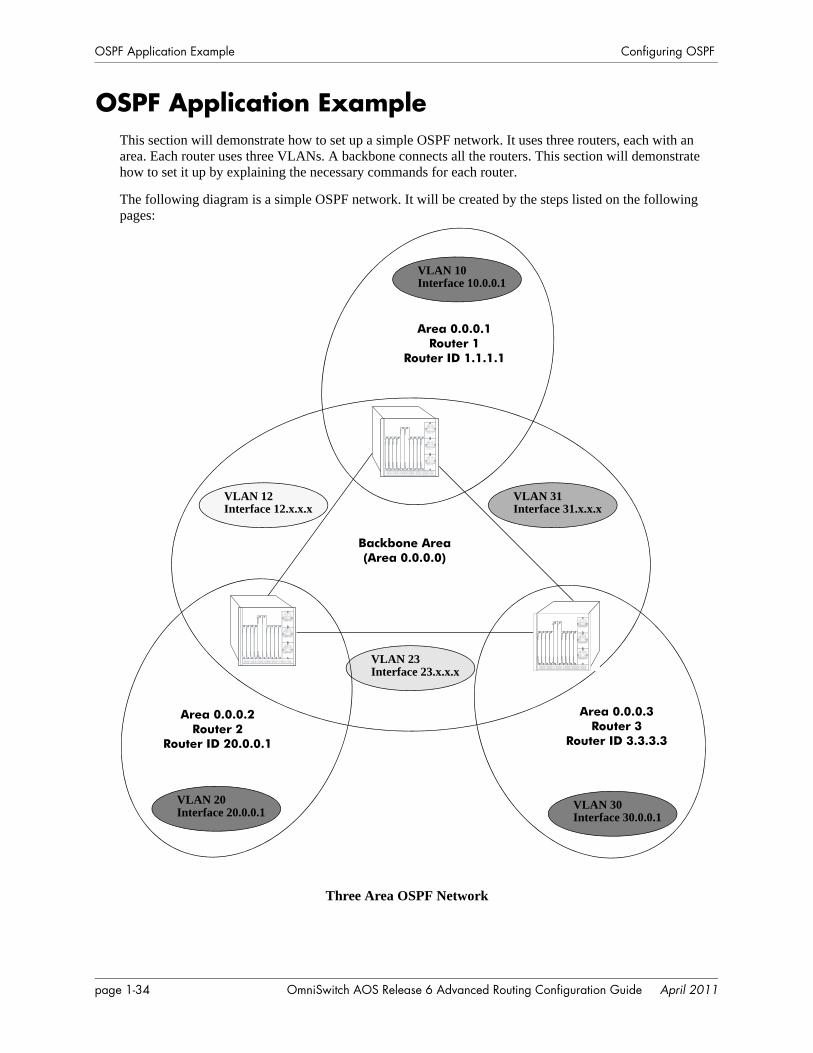
OSPF Application Example Configuring OSPF
OSPF Application ExampleThis section will demonstrate how to set up a simple OSPF network. It uses three routers, each with an area. Each router uses three VLANs. A backbone connects all the routers. This section will demonstrate how to set it up by explaining the necessary commands for each router.
The following diagram is a simple OSPF network. It will be created by the steps listed on the following pages:
Three Area OSPF Network
Backbone Area(Area 0.0.0.0)
Area 0.0.0.1Router 1
Router ID 1.1.1.1
Area 0.0.0.2Router 2
Router ID 20.0.0.1
Area 0.0.0.3Router 3
Router ID 3.3.3.3
VLAN 10Interface 10.0.0.1
VLAN 20Interface 20.0.0.1
VLAN 12Interface 12.x.x.x
VLAN 30Interface 30.0.0.1
VLAN 23Interface 23.x.x.x
VLAN 31Interface 31.x.x.x
page 1-34 OmniSwitch AOS Release 6 Advanced Routing Configuration Guide April 2011
Configuring OSPF OSPF Application Example
Step 1: Prepare the RoutersThe first step is to create the VLANs on each router, add an IP interface to the VLAN, assign a port to the VLAN, and assign a router identification number to the routers. For the backbone, the network design in this case uses slot 2, port 1 as the egress port and slot 2, port 2 as ingress port on each router. Router 1 connects to Router 2, Router 2 connects to Router 3, and Router 3 connects to Router 1 using 10/100 Ethernet cables.
Note. The ports will be statically assigned to the router, as a VLAN must have a physical port assigned to it in order for the router port to function. However, the router could be set up in such a way that mobile ports are dynamically assigned to VLANs using VLAN rules. See the chapter titled “Defining VLAN Rules” in the OmniSwitch AOS Release 6 Network Configuration Guide.
The commands setting up VLANs are shown below:
Router 1 (using ports 2/1 and 2/2 for the backbone, and ports 2/3-5 for end devices):
-> vlan 31-> ip interface vlan-31 vlan 31 address 31.0.0.1 mask 255.0.0.0-> vlan 31 port default 2/1
-> vlan 12-> ip interface vlan-12 vlan 12 address 12.0.0.1 mask 255.0.0.0-> vlan 12 port default 2/2
-> vlan 10-> ip interface vlan-10 vlan 10 address 10.0.0.1 mask 255.0.0.0-> vlan 10 port default 2/3-5
-> ip router router-id 1.1.1.1
These commands created VLANs 31, 12, and 10.
• VLAN 31 handles the backbone connection from Router 1 to Router 3, using the IP router port 31.0.0.1 and physical port 2/1.
• VLAN 12 handles the backbone connection from Router 1 to Router 2, using the IP router port 12.0.0.1 and physical port 2/2.
• VLAN 10 handles the device connections to Router 1, using the IP router port 10.0.0.1 and physical ports 2/3-5. More ports could be added at a later time if necessary.
The router was assigned the Router ID of 1.1.1.1.
Router 2 (using ports 2/1 and 2/2 for the backbone, and ports 2/3-5 for end devices):
-> vlan 12-> ip interface vlan-12 vlan 12 address 12.0.0.2 mask 255.0.0.0-> vlan 12 port default 2/1
-> vlan 23-> ip interface vlan-23 vlan 23 address 23.0.0.2 mask 255.0.0.0-> vlan 23 port default 2/2
-> vlan 20-> ip interface vlan-20 vlan 20 address 20.0.0.2 mask 255.0.0.0-> vlan 20 port default 2/3-5
OmniSwitch AOS Release 6 Advanced Routing Configuration Guide April 2011 page 1-35
OSPF Application Example Configuring OSPF
-> ip router router-id 2.2.2.2
These commands created VLANs 12, 23, and 20.
• VLAN 12 handles the backbone connection from Router 1 to Router 2, using the IP router port 12.0.0.2 and physical port 2/1.
• VLAN 23 handles the backbone connection from Router 2 to Router 3, using the IP router port 23.0.0.2 and physical port 2/2.
• VLAN 20 handles the device connections to Router 2, using the IP router port 20.0.0.2 and physical ports 2/3-5. More ports could be added at a later time if necessary.
The router was assigned the Router ID of 2.2.2.2.
Router 3 (using ports 2/1 and 2/2 for the backbone, and ports 2/3-5 for end devices):
-> vlan 23-> ip interface vlan-23 vlan 23 address 23.0.0.3 mask 255.0.0.0-> vlan 23 port default 2/1
-> vlan 31-> ip interface vlan-31 vlan 31 address 31.0.0.3 mask 255.0.0.0-> vlan 31 port default 2/2
-> vlan 30-> ip interface vlan-30 vlan 30 address 30.0.0.3 mask 255.0.0.0-> vlan 30 port default 2/3-5
-> ip router router-id 3.3.3.3
These commands created VLANs 23, 31, and 30.
• VLAN 23 handles the backbone connection from Router 2 to Router 3, using the IP router port 23.0.0.3 and physical port 2/1.
• VLAN 31 handles the backbone connection from Router 3 to Router 1, using the IP router port 31.0.0.3 and physical port 2/2.
• VLAN 30 handles the device connections to Router 3, using the IP router port 30.0.0.3 and physical ports 2/3-5. More ports could be added at a later time if necessary.
The router was assigned the Router ID of 3.3.3.3.
Step 2: Enable OSPFThe next step is to load and enable OSPF on each router. The commands for this step are below (the commands are the same on each router):
-> ip load ospf-> ip ospf status enable
Step 3: Create the Areas and BackboneNow the areas should be created. In this case, we will create an area for each router, and a backbone (area 0.0.0.0) that connects the areas.
page 1-36 OmniSwitch AOS Release 6 Advanced Routing Configuration Guide April 2011
Configuring OSPF OSPF Application Example
The commands for this step are below:
Router 1
-> ip ospf area 0.0.0.0-> ip ospf area 0.0.0.1These commands created area 0.0.0.0 (the backbone) and area 0.0.0.1 (the area for Router 1). Both of these areas are also enabled.
Router 2
-> ip ospf area 0.0.0.0-> ip ospf area 0.0.0.2These commands created Area 0.0.0.0 (the backbone) and Area 0.0.0.2 (the area for Router 2). Both of these areas are also enabled.
Router 3
-> ip ospf area 0.0.0.0-> ip ospf area 0.0.0.3These commands created Area 0.0.0.0 (the backbone) and Area 0.0.0.3 (the area for Router 3). Both of these areas are also enabled.
Step 4: Create, Enable, and Assign InterfacesNext, OSPF interfaces must be created, enabled, and assigned to the areas. The OSPF interfaces should have the same interface name as the IP router ports created above in “Step 1: Prepare the Routers” on page 1-35.
Router 1
-> ip ospf interface vlan-31-> ip ospf interface vlan-31 area 0.0.0.0-> ip ospf interface vlan-31 status enable
-> ip ospf interface vlan-12-> ip ospf interface vlan-12 area 0.0.0.0-> ip ospf interface vlan-12 status enable
-> ip ospf interface vlan-10-> ip ospf interface vlan-10 area 0.0.0.1-> ip ospf interface vlan-10 status enable
IP router port 31.0.0.1 was associated to OSPF interface vlan-31, enabled, and assigned to the backbone. IP router port 12.0.0.1 was associated to OSPF interface vlan-12, enabled, and assigned to the backbone. IP router port 10.0.0.1 which connects to end stations and attached network devices, was associated to OSPF interface vlan-10, enabled, and assigned to Area 0.0.0.1.
Router 2
-> ip ospf interface vlan-12-> ip ospf interface vlan-12 area 0.0.0.0-> ip ospf interface vlan-12 status enable
-> ip ospf interface vlan-23-> ip ospf interface vlan-23 area 0.0.0.0-> ip ospf interface vlan-23 status enable
OmniSwitch AOS Release 6 Advanced Routing Configuration Guide April 2011 page 1-37
OSPF Application Example Configuring OSPF
-> ip ospf interface vlan-20-> ip ospf interface vlan-20 area 0.0.0.2-> ip ospf interface vlan-20 status enable
IP router port 12.0.0.2 was associated to OSPF interface vlan-12, enabled, and assigned to the backbone. IP router port 23.0.0.2 was associated to OSPF interface vlan-23, enabled, and assigned to the backbone. IP router port 20.0.0.2, which connects to end stations and attached network devices, was associated to OSPF interface vlan-20, enabled, and assigned to Area 0.0.0.2.
Router 3
-> ip ospf interface vlan-23-> ip ospf interface vlan-23 area 0.0.0.0-> ip ospf interface vlan-23 status enable
-> ip ospf interface vlan-31-> ip ospf interface vlan-31 area 0.0.0.0-> ip ospf interface vlan-31 status enable
-> ip ospf interface vlan-30-> ip ospf interface vlan-30 area 0.0.0.3-> ip ospf interface vlan-30 status enable
IP router port 23.0.0.3 was associated to OSPF interface vlan-23, enabled, and assigned to the backbone. IP router port 31.0.0.3 was associated to OSPF interface vlan-31, enabled, and assigned to the backbone. IP router port 30.0.0.3, which connects to end stations and attached network devices, was associated to OSPF interface vlan-30, enabled, and assigned to Area 0.0.0.3.
Step 5: Examine the NetworkAfter the network has been created, you can check various aspects of it using show commands:
• For OSPF in general, use the show ip ospf command.
• For areas, use the show ip ospf area command.
• For interfaces, use the show ip ospf interface command.
• To check for adjacencies formed with neighbors, use the show ip ospf neighbor command.
• For routes, use the show ip ospf routes command.
page 1-38 OmniSwitch AOS Release 6 Advanced Routing Configuration Guide April 2011
Configuring OSPF Verifying OSPF Configuration
Verifying OSPF ConfigurationTo display information about areas, interfaces, virtual links, redistribution, or OPSF in general, use the show commands listed in the following table:
For more information about the resulting displays form these commands, see the “OSPF Commands” chapter in the OmniSwitch CLI Reference Guide.
Examples of the show ip ospf, show ip ospf area, and show ip ospf interface command outputs are given in the section “OSPF Quick Steps” on page 1-4.
show ip ospf Displays OSPF status and general configuration parameters.show ip ospf border-routers Displays information regarding all or specified border routers.show ip ospf ext-lsdb Displays external Link State Advertisements from the areas to which the
router is attached.show ip ospf host Displays information on directly attached hosts.show ip ospf lsdb Displays LSAs in the Link State Database associated with each area.show ip ospf neighbor Displays information on OSPF non-virtual neighbor routers.show ip redist Displays the route map redistribution configuration.show ip ospf routes Displays OSPF routes known to the router.show ip ospf virtual-link Displays virtual link information.show ip ospf virtual-neighbor Displays OSPF virtual neighbors.show ip ospf area Displays either all OSPF areas, or a specified OSPF area.show ip ospf area range Displays all or specified configured area address range summaries for
the given area.show ip ospf area stub Displays stub area status.show ip ospf interface Displays OSPF interface information.show ip ospf restart Displays the OSPF graceful restart related configuration and status.
OmniSwitch AOS Release 6 Advanced Routing Configuration Guide April 2011 page 1-39

Verifying OSPF Configuration Configuring OSPF
page 1-40 OmniSwitch AOS Release 6 Advanced Routing Configuration Guide April 2011
2 Configuring OSPFv3
Open Shortest Path First version 3 (OSPFv3) is an extension of OSPF version 2 that provides support for networks using the IPv6 protocol. OSPFv2 is for IPv4 networks (see Chapter 1, “Configuring OSPF,” for more information about OSPFv2).
In This ChapterThis chapter describes the basic components of OSPFv3 and how to configure them through the Command Line Interface (CLI). CLI commands are used in the configuration examples; for more details about the syntax of commands, see the OmniSwitch CLI Reference Guide.
Configuration procedures described in this chapter include:
• Loading and enabling OSPFv3. See “Activating OSPFv3” on page 2-14.
• Creating OSPFv3 areas. See “Creating an OSPFv3 Area” on page 2-15.
• Creating OSPFv3 interfaces. See “Creating OSPFv3 Interfaces” on page 2-16.
• Creating virtual links. See “Creating Virtual Links” on page 2-17.
• Configuring redistribution using route map. See “Configuring Redistribution” on page 2-18.
For information on creating and managing VLANs, see “Configuring VLANs” in the OmniSwitch AOS Release 6 Network Configuration Guide.
OmniSwitch AOS Release 6 Advanced Routing Configuration Guide April 2011 page 2-1
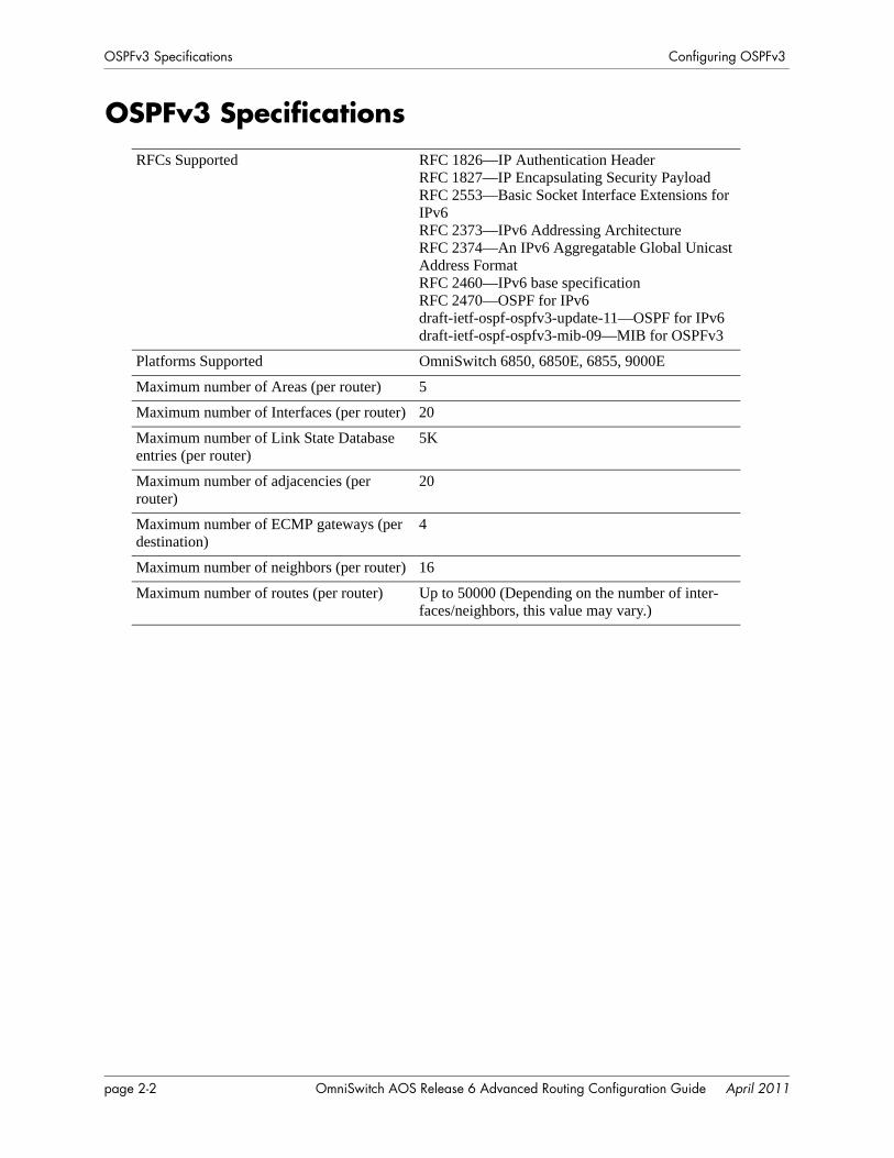
OSPFv3 Specifications Configuring OSPFv3
OSPFv3 SpecificationsRFCs Supported RFC 1826—IP Authentication Header
RFC 1827—IP Encapsulating Security PayloadRFC 2553—Basic Socket Interface Extensions for IPv6RFC 2373—IPv6 Addressing ArchitectureRFC 2374—An IPv6 Aggregatable Global Unicast Address FormatRFC 2460—IPv6 base specificationRFC 2470—OSPF for IPv6draft-ietf-ospf-ospfv3-update-11—OSPF for IPv6draft-ietf-ospf-ospfv3-mib-09—MIB for OSPFv3
Platforms Supported OmniSwitch 6850, 6850E, 6855, 9000E
Maximum number of Areas (per router) 5
Maximum number of Interfaces (per router) 20
Maximum number of Link State Database entries (per router)
5K
Maximum number of adjacencies (per router)
20
Maximum number of ECMP gateways (per destination)
4
Maximum number of neighbors (per router) 16
Maximum number of routes (per router) Up to 50000 (Depending on the number of inter-faces/neighbors, this value may vary.)
page 2-2 OmniSwitch AOS Release 6 Advanced Routing Configuration Guide April 2011
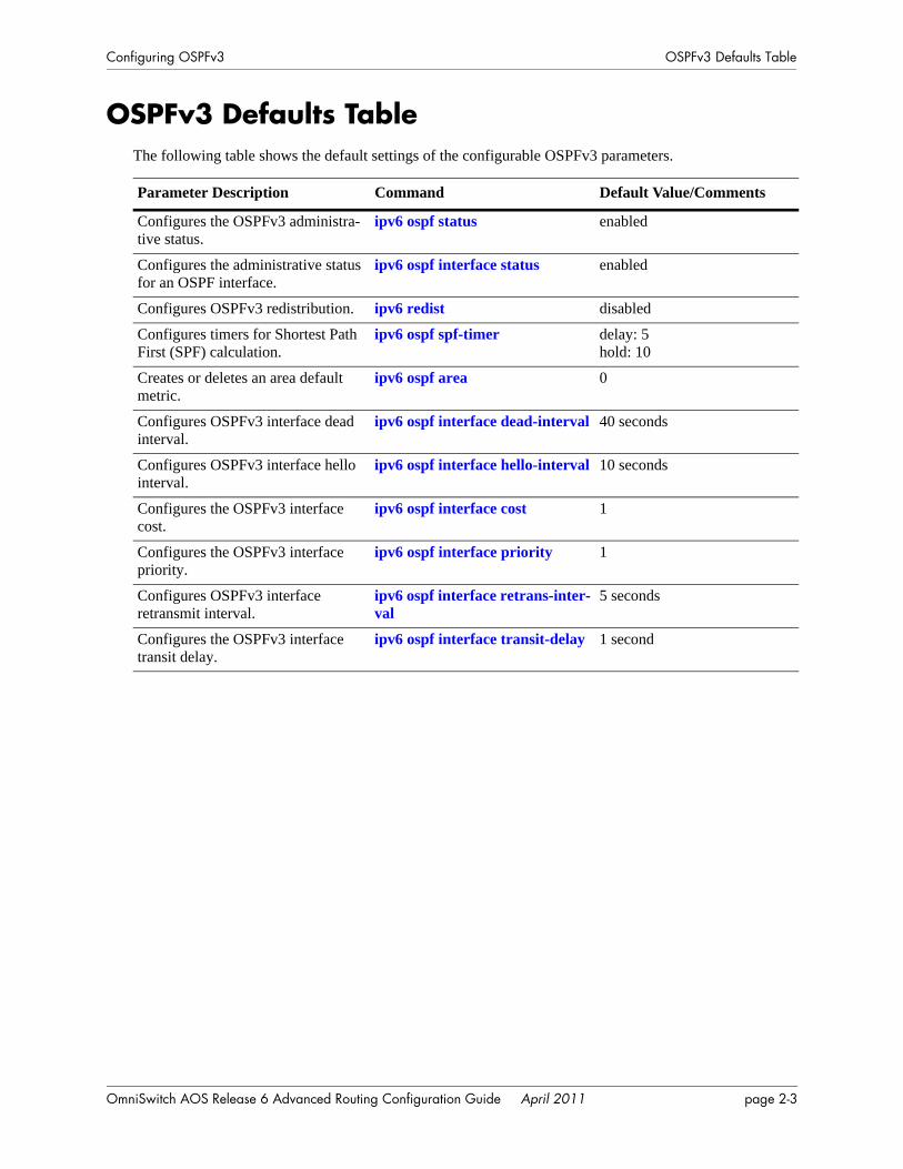
Configuring OSPFv3 OSPFv3 Defaults Table
OSPFv3 Defaults TableThe following table shows the default settings of the configurable OSPFv3 parameters.
Parameter Description Command Default Value/Comments
Configures the OSPFv3 administra-tive status.
ipv6 ospf status enabled
Configures the administrative status for an OSPF interface.
ipv6 ospf interface status enabled
Configures OSPFv3 redistribution. ipv6 redist disabled
Configures timers for Shortest Path First (SPF) calculation.
ipv6 ospf spf-timer delay: 5hold: 10
Creates or deletes an area default metric.
ipv6 ospf area 0
Configures OSPFv3 interface dead interval.
ipv6 ospf interface dead-interval 40 seconds
Configures OSPFv3 interface hello interval.
ipv6 ospf interface hello-interval 10 seconds
Configures the OSPFv3 interface cost.
ipv6 ospf interface cost 1
Configures the OSPFv3 interface priority.
ipv6 ospf interface priority 1
Configures OSPFv3 interface retransmit interval.
ipv6 ospf interface retrans-inter-val
5 seconds
Configures the OSPFv3 interface transit delay.
ipv6 ospf interface transit-delay 1 second
OmniSwitch AOS Release 6 Advanced Routing Configuration Guide April 2011 page 2-3
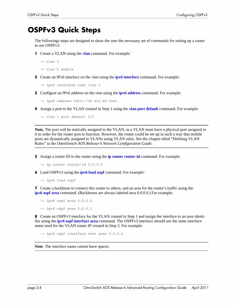
OSPFv3 Quick Steps Configuring OSPFv3
OSPFv3 Quick StepsThe followings steps are designed to show the user the necessary set of commands for setting up a router to use OSPFv3:
1 Create a VLAN using the vlan command. For example:
-> vlan 5
-> vlan 5 enable
2 Create an IPv6 interface on the vlan using the ipv6 interface command. For example:
-> ipv6 interface test vlan 1
3 Configure an IPv6 address on the vlan using the ipv6 address command. For example:
-> ipv6 address 2001::/64 eui-64 test
4 Assign a port to the VLAN created in Step 1 using the vlan port default command. For example:
-> vlan 1 port default 2/1
Note. The port will be statically assigned to the VLAN, as a VLAN must have a physical port assigned to it in order for the router port to function. However, the router could be set up in such a way that mobile ports are dynamically assigned to VLANs using VLAN rules. See the chapter titled “Defining VLAN Rules” in the OmniSwitch AOS Release 6 Network Configuration Guide.
5 Assign a router ID to the router using the ip router router-id command. For example:
-> ip router router-id 5.5.5.5
6 Load OSPFv3 using the ipv6 load ospf command. For example:
-> ipv6 load ospf
7 Create a backbone to connect this router to others, and an area for the router’s traffic using theipv6 ospf area command. (Backbones are always labeled area 0.0.0.0.) For example:
-> ipv6 ospf area 0.0.0.0
-> ipv6 ospf area 0.0.0.1
8 Create an OSPFv3 interface for the VLAN created in Step 1 and assign the interface to an area identi-fier using the ipv6 ospf interface area command. The OSPFv3 interface should use the same interface name used for the VLAN router IP created in Step 2. For example:
-> ipv6 ospf interface test area 0.0.0.0
Note. The interface name cannot have spaces.
page 2-4 OmniSwitch AOS Release 6 Advanced Routing Configuration Guide April 2011

Configuring OSPFv3 OSPFv3 Quick Steps
9 You can now display the router OSPFv3 settings by using the show ipv6 ospf command. The output generated is similar to the following:
10 You can display OSPFv3 area settings using the show ipv6 ospf area command. For example:
-> show ipv6 ospf
Status = Enabled,Router ID = 5.5.5.5,# Areas = 2,# Interfaces = 4,Area Border Router = Yes,AS Border Router = No,External Route Tag = 0,SPF Hold (seconds) = 10,SPF Delay (seconds) = 5,MTU checking = Enabled,# SPF calculations performed = 3,Last SPF run (seconds ago) = N/A,# of neighbors that are in:Full state = 3,Loading state = 0,Exchange state = 0,Exstart state = 0,2way state = 0,Init state = 0,Attempt state = 0,Down state = 0
Router IDAs set in Step 5
-> show ipv6 ospf area
Stub Number ofArea ID Type Metric Interfaces---------------+-------+------+------------------------0.0.0.0 Normal NA 20.0.0.1 Normal NA 2
Area ID As set in Step 6
OmniSwitch AOS Release 6 Advanced Routing Configuration Guide April 2011 page 2-5
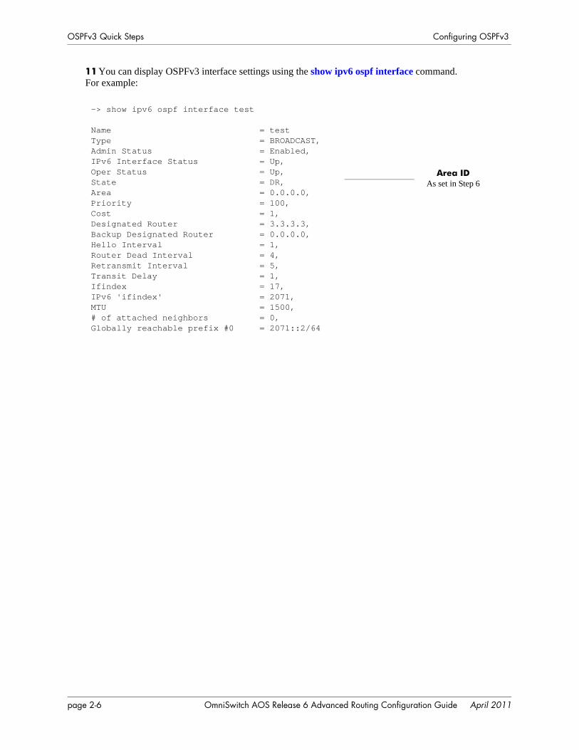
OSPFv3 Quick Steps Configuring OSPFv3
11 You can display OSPFv3 interface settings using the show ipv6 ospf interface command. For example:
-> show ipv6 ospf interface test
Name = testType = BROADCAST,Admin Status = Enabled,IPv6 Interface Status = Up,Oper Status = Up,State = DR,Area = 0.0.0.0,Priority = 100,Cost = 1,Designated Router = 3.3.3.3,Backup Designated Router = 0.0.0.0,Hello Interval = 1,Router Dead Interval = 4,Retransmit Interval = 5,Transit Delay = 1,Ifindex = 17,IPv6 'ifindex' = 2071,MTU = 1500,# of attached neighbors = 0,Globally reachable prefix #0 = 2071::2/64
Area ID As set in Step 6
page 2-6 OmniSwitch AOS Release 6 Advanced Routing Configuration Guide April 2011
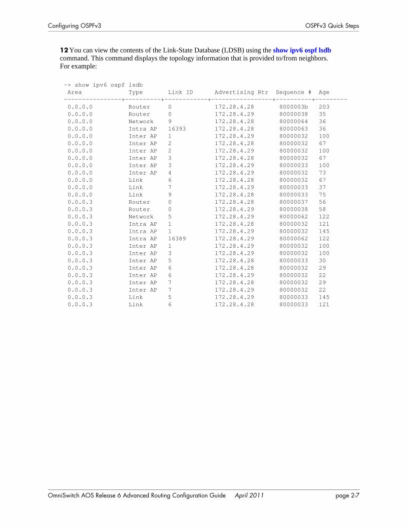
Configuring OSPFv3 OSPFv3 Quick Steps
12 You can view the contents of the Link-State Database (LDSB) using the show ipv6 ospf lsdb command. This command displays the topology information that is provided to/from neighbors. For example:
-> show ipv6 ospf lsdb Area Type Link ID Advertising Rtr Sequence # Age----------------+----------+------------+-----------------+----------+--------- 0.0.0.0 Router 0 172.28.4.28 8000003b 203 0.0.0.0 Router 0 172.28.4.29 80000038 35 0.0.0.0 Network 9 172.28.4.28 80000064 36 0.0.0.0 Intra AP 16393 172.28.4.28 80000063 36 0.0.0.0 Inter AP 1 172.28.4.29 80000032 100 0.0.0.0 Inter AP 2 172.28.4.28 80000032 67 0.0.0.0 Inter AP 2 172.28.4.29 80000032 100 0.0.0.0 Inter AP 3 172.28.4.28 80000032 67 0.0.0.0 Inter AP 3 172.28.4.29 80000033 100 0.0.0.0 Inter AP 4 172.28.4.29 80000032 73 0.0.0.0 Link 6 172.28.4.28 80000032 67 0.0.0.0 Link 7 172.28.4.29 80000033 37 0.0.0.0 Link 9 172.28.4.28 80000033 75 0.0.0.3 Router 0 172.28.4.28 80000037 56 0.0.0.3 Router 0 172.28.4.29 80000038 58 0.0.0.3 Network 5 172.28.4.29 80000062 122 0.0.0.3 Intra AP 1 172.28.4.28 80000032 121 0.0.0.3 Intra AP 1 172.28.4.29 80000032 145 0.0.0.3 Intra AP 16389 172.28.4.29 80000062 122 0.0.0.3 Inter AP 1 172.28.4.29 80000032 100 0.0.0.3 Inter AP 3 172.28.4.29 80000032 100 0.0.0.3 Inter AP 5 172.28.4.28 80000033 30 0.0.0.3 Inter AP 6 172.28.4.28 80000032 29 0.0.0.3 Inter AP 6 172.28.4.29 80000032 22 0.0.0.3 Inter AP 7 172.28.4.28 80000032 29 0.0.0.3 Inter AP 7 172.28.4.29 80000032 22 0.0.0.3 Link 5 172.28.4.29 80000033 145 0.0.0.3 Link 6 172.28.4.28 80000033 121
OmniSwitch AOS Release 6 Advanced Routing Configuration Guide April 2011 page 2-7
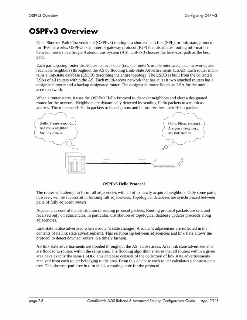
OSPFv3 Overview Configuring OSPFv3
OSPFv3 OverviewOpen Shortest Path First version 3 (OSPFv3) routing is a shortest path first (SPF), or link-state, protocol for IPv6 networks. OSPFv3 is an interior gateway protocol (IGP) that distributes routing information between routers in a Single Autonomous System (AS). OSPFv3 chooses the least-cost path as the best path.
Each participating router distributes its local state (i.e., the router’s usable interfaces, local networks, and reachable neighbors) throughout the AS by flooding Link-State Advertisements (LSAs). Each router main-tains a link-state database (LSDB) describing the entire topology. The LSDB is built from the collected LSAs of all routers within the AS. Each multi-access network that has at least two attached routers has a designated router and a backup designated router. The designated router floods an LSA for the multi-access network.
When a router starts, it uses the OSPFv3 Hello Protocol to discover neighbors and elect a designated router for the network. Neighbors are dynamically detected by sending Hello packets to a multicast address. The router sends Hello packets to its neighbors and in turn receives their Hello packets.
OSPFv3 Hello Protocol
The router will attempt to form full adjacencies with all of its newly acquired neighbors. Only some pairs, however, will be successful in forming full adjacencies. Topological databases are synchronized between pairs of fully adjacent routers.
Adjacencies control the distribution of routing protocol packets. Routing protocol packets are sent and received only on adjacencies. In particular, distribution of topological database updates proceeds along adjacencies.
Link state is also advertised when a router’s state changes. A router’s adjacencies are reflected in the contents of its link state advertisements. This relationship between adjacencies and link state allows the protocol to detect downed routers in a timely fashion.
AS link state advertisements are flooded throughout the AS, across areas. Area link state advertisements are flooded to routers within the same area. The flooding algorithm ensures that all routers within a given area have exactly the same LSDB. This database consists of the collection of link state advertisements received from each router belonging to the area. From this database each router calculates a shortest-path tree. This shortest-path tree in turn yields a routing table for the protocol.
Hello. Please respond...Are you a neighbor...
Hello. Please respond...Are you a neighbor...
My link state is... My link state is...
page 2-8 OmniSwitch AOS Release 6 Advanced Routing Configuration Guide April 2011
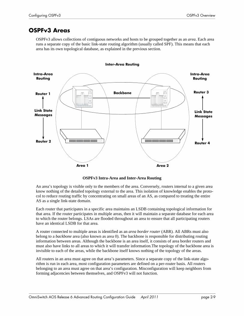
Configuring OSPFv3 OSPFv3 Overview
OSPFv3 AreasOSPFv3 allows collections of contiguous networks and hosts to be grouped together as an area. Each area runs a separate copy of the basic link-state routing algorithm (usually called SPF). This means that each area has its own topological database, as explained in the previous section.
OSPFv3 Intra-Area and Inter-Area Routing
An area’s topology is visible only to the members of the area. Conversely, routers internal to a given area know nothing of the detailed topology external to the area. This isolation of knowledge enables the proto-col to reduce routing traffic by concentrating on small areas of an AS, as compared to treating the entire AS as a single link-state domain.
Each router that participates in a specific area maintains an LSDB containing topological information for that area. If the router participates in multiple areas, then it will maintain a separate database for each area to which the router belongs. LSAs are flooded throughout an area to ensure that all participating routers have an identical LSDB for that area.
A router connected to multiple areas is identified as an area border router (ABR). All ABRs must also belong to a backbone area (also known as area 0). The backbone is responsible for distributing routing information between areas. Although the backbone is an area itself, it consists of area border routers and must also have links to all areas to which it will transfer information.The topology of the backbone area is invisible to each of the areas, while the backbone itself knows nothing of the topology of the areas.
All routers in an area must agree on that area’s parameters. Since a separate copy of the link-state algo-rithm is run in each area, most configuration parameters are defined on a per-router basis. All routers belonging to an area must agree on that area’s configuration. Misconfiguration will keep neighbors from forming adjacencies between themselves, and OSPFv3 will not function.
Inter-Area Routing
Backbone
Intra-AreaRouting
Intra-AreaRouting
Router 1
Router 2
Router 3
Router 4
Link State Messages
Link State Messages
Area 1 Area 2
OmniSwitch AOS Release 6 Advanced Routing Configuration Guide April 2011 page 2-9
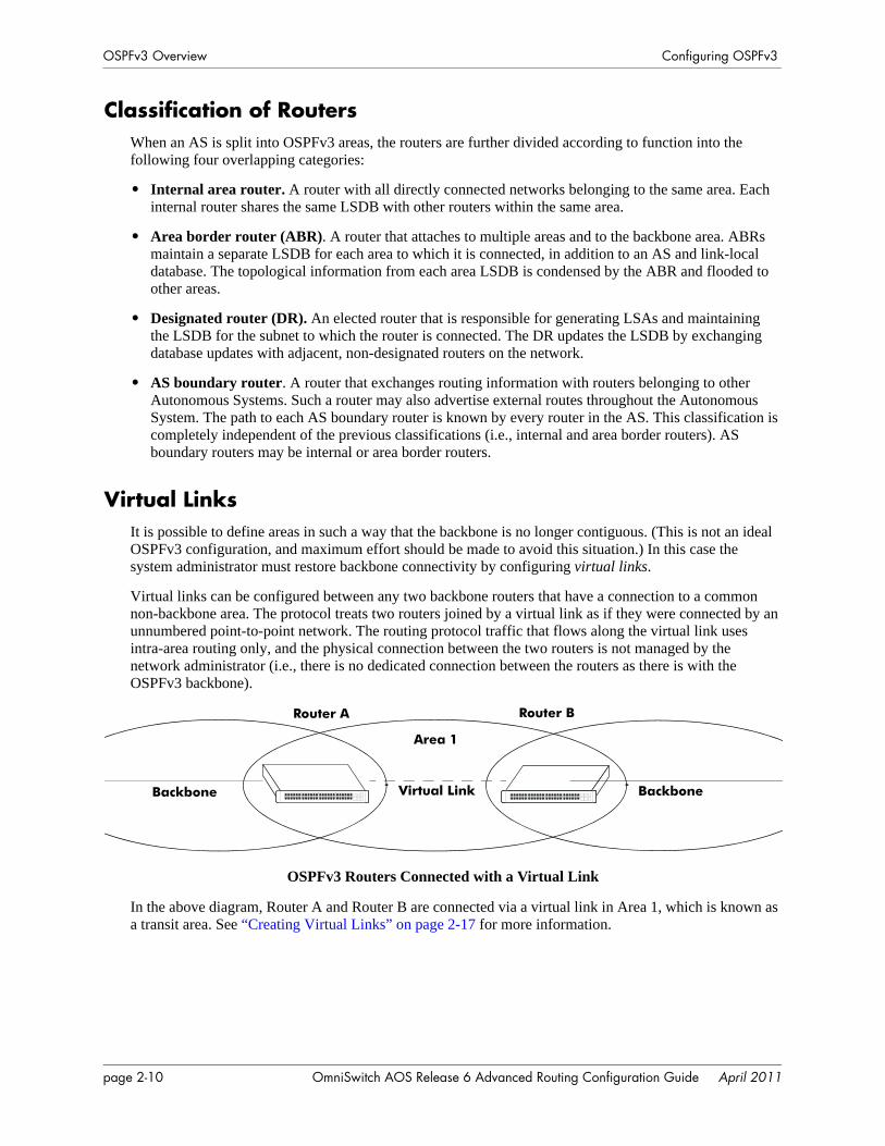
OSPFv3 Overview Configuring OSPFv3
Classification of RoutersWhen an AS is split into OSPFv3 areas, the routers are further divided according to function into the following four overlapping categories:
• Internal area router. A router with all directly connected networks belonging to the same area. Each internal router shares the same LSDB with other routers within the same area.
• Area border router (ABR). A router that attaches to multiple areas and to the backbone area. ABRs maintain a separate LSDB for each area to which it is connected, in addition to an AS and link-local database. The topological information from each area LSDB is condensed by the ABR and flooded to other areas.
• Designated router (DR). An elected router that is responsible for generating LSAs and maintaining the LSDB for the subnet to which the router is connected. The DR updates the LSDB by exchanging database updates with adjacent, non-designated routers on the network.
• AS boundary router. A router that exchanges routing information with routers belonging to other Autonomous Systems. Such a router may also advertise external routes throughout the Autonomous System. The path to each AS boundary router is known by every router in the AS. This classification is completely independent of the previous classifications (i.e., internal and area border routers). AS boundary routers may be internal or area border routers.
Virtual LinksIt is possible to define areas in such a way that the backbone is no longer contiguous. (This is not an ideal OSPFv3 configuration, and maximum effort should be made to avoid this situation.) In this case the system administrator must restore backbone connectivity by configuring virtual links.
Virtual links can be configured between any two backbone routers that have a connection to a common non-backbone area. The protocol treats two routers joined by a virtual link as if they were connected by an unnumbered point-to-point network. The routing protocol traffic that flows along the virtual link uses intra-area routing only, and the physical connection between the two routers is not managed by the network administrator (i.e., there is no dedicated connection between the routers as there is with the OSPFv3 backbone).
OSPFv3 Routers Connected with a Virtual Link
In the above diagram, Router A and Router B are connected via a virtual link in Area 1, which is known as a transit area. See “Creating Virtual Links” on page 2-17 for more information.
Router A Router B
Backbone Virtual Link
Area 1
Backbone
page 2-10 OmniSwitch AOS Release 6 Advanced Routing Configuration Guide April 2011
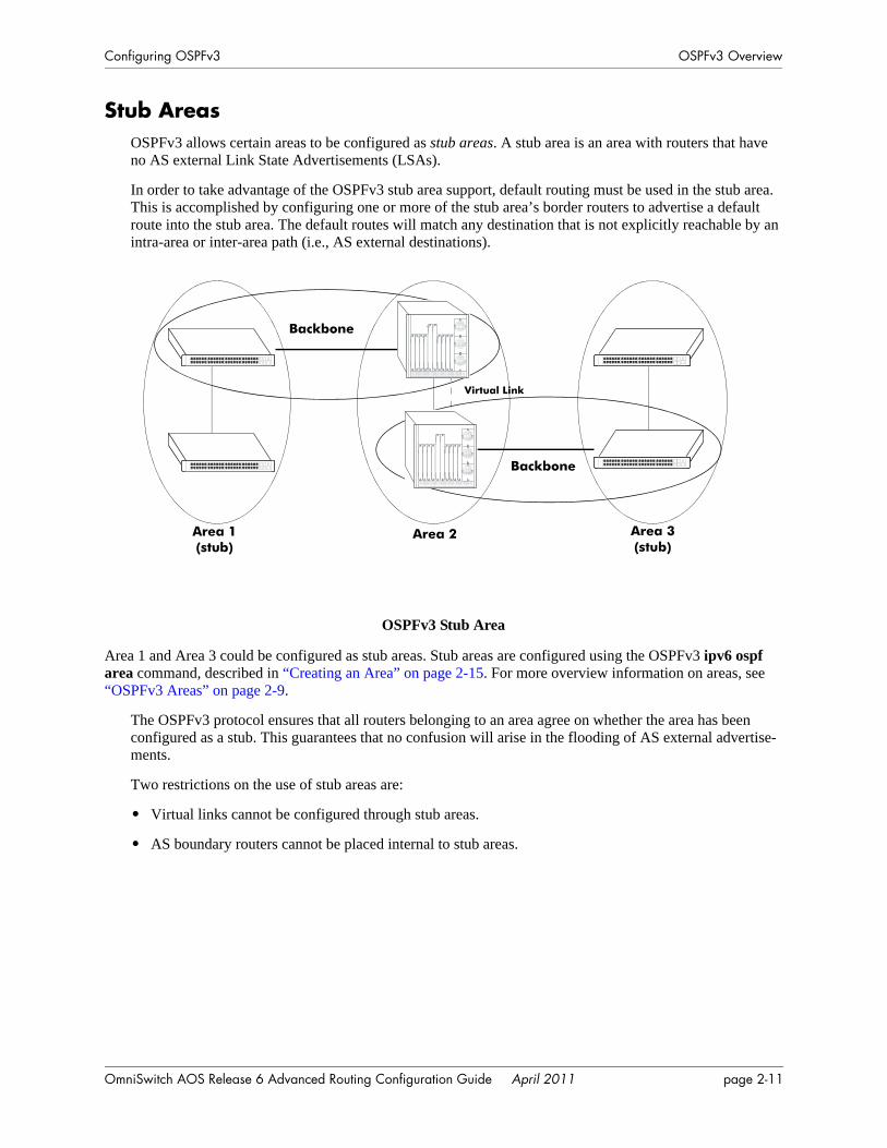
Configuring OSPFv3 OSPFv3 Overview
Stub AreasOSPFv3 allows certain areas to be configured as stub areas. A stub area is an area with routers that have no AS external Link State Advertisements (LSAs).
In order to take advantage of the OSPFv3 stub area support, default routing must be used in the stub area. This is accomplished by configuring one or more of the stub area’s border routers to advertise a default route into the stub area. The default routes will match any destination that is not explicitly reachable by an intra-area or inter-area path (i.e., AS external destinations).
OSPFv3 Stub Area
Area 1 and Area 3 could be configured as stub areas. Stub areas are configured using the OSPFv3 ipv6 ospf area command, described in “Creating an Area” on page 2-15. For more overview information on areas, see “OSPFv3 Areas” on page 2-9.
The OSPFv3 protocol ensures that all routers belonging to an area agree on whether the area has been configured as a stub. This guarantees that no confusion will arise in the flooding of AS external advertise-ments.
Two restrictions on the use of stub areas are:
• Virtual links cannot be configured through stub areas.
• AS boundary routers cannot be placed internal to stub areas.
Virtual Link
Area 3(stub)
Area 2Area 1(stub)
Backbone
Backbone
OmniSwitch AOS Release 6 Advanced Routing Configuration Guide April 2011 page 2-11

OSPFv3 Overview Configuring OSPFv3
Equal Cost Multi-Path (ECMP) RoutingUsing information from its continuously updated databases, OSPFv3 calculates the shortest path to a given destination. Shortest path is determined from metric values at each hop along a path. At times, two or more paths to the same destination will have the same metric cost.
In the network illustration below, there are two paths from Source router A to Destination router B. One path traverses two hops at routers X and Y and the second path traverses two hops at M and N. If the total cost through X and Y to B is the same as the cost via M and N to B, then these two paths have equal cost. In this version of OSPFv3 both paths will be stored and used to transmit data.
Multiple Equal Cost Paths
Delivery of packets along equal paths is based on flows rather than a round-robin scheme. Equal cost is determined based on standard routing metrics. However, other variables, such as line speed, are not considered. So it is possible for OSPFv3 to decide two paths have an equal cost even though one may contain faster links than another.
Source (A) Destination (B)
X Y
M N
A-> X-> Y-> B = A-> M-> N-> B
page 2-12 OmniSwitch AOS Release 6 Advanced Routing Configuration Guide April 2011
Configuring OSPFv3 Configuring OSPFv3
Configuring OSPFv3Configuring OSPFv3 on a router requires several steps. Depending on your requirements, you may not need to perform all of the steps listed below.
By default, OSPFv3 is enabled on the router. Configuring OSPFv3 consists of these tasks:
• Set up the basics of the OSPFv3 network by configuring the required VLANs, assigning ports to the VLANs, and assigning router identification numbers to the routers involved. This is described in “Preparing the Network for OSPFv3” on page 2-14.
• Load OSPFv3. When the image file for advanced routing is installed, you must load the OSPFv3 code. The commands for loading OSPFv3 are described in “Activating OSPFv3” on page 2-14.
• Create any desired OSPFv3 areas, including the backbone area if one is required. Note that a backbone area is not necessary if there is only one area. The commands to create areas and backbone areas are described in “Creating an OSPFv3 Area” on page 2-15.
• Set area parameters (optional). OSPFv3 will run with the default area parameters, but different networks may benefit from modifying the parameters. Modifying area parameters is described in “Configuring Stub Area Default Metrics” on page 2-16.
• Create OSPFv3 interfaces. OSPFv3 interfaces are created and assigned to areas. Creating interfaces is described in “Creating an Interface” on page 1-20, and assigning interfaces is described in “Assigning an Interface to an Area” on page 1-20.
• Set interface parameters (optional). OSPFv3 will run with the default interface parameters, but differ-ent networks may benefit from modifying the parameters. Also, it is possible to set authentication on an interface.
• Configure virtual links (optional). A virtual link is used to establish backbone connectivity when two backbone routers are not physically contiguous. To create a virtual link, see “Creating Virtual Links” on page 2-17.
• Configure redistribution using route maps (optional). Redistribution allows the control of how routes are advertised into the OSPFv3 network from outside the Autonomous System. Configuring redistribu-tion is described in “Configuring Redistribution” on page 2-18.
• Configure router capabilities (optional). There are several commands that influence router operation. These are covered briefly in a table in “Configuring Router Capabilities” on page 2-24.
At the end of the chapter is a simple OSPFv3 network diagram with instructions on how it was created on a router-by-router basis. See “OSPFv3 Application Example” on page 2-25 for more information.
OmniSwitch AOS Release 6 Advanced Routing Configuration Guide April 2011 page 2-13
Configuring OSPFv3 Configuring OSPFv3
Preparing the Network for OSPFv3OSPFv3 operates on top of normal switch functions, using existing ports, virtual ports, VLANs, etc. The following network components should already be configured:
• Configure VLANs that are to be used in the OSPFv3 network. VLANS should be created for inter-faces that will participate in the OSPFv3 network. VLAN configuration is described in “Configuring VLANs” in the OmniSwitch AOS Release 6 Network Configuration Guide.
• Assign IPv6 interfaces to the VLANs. IPv6 interfaces must be assigned to the VLAN. Assigning IPv6 interfaces is described in “Configuring IP” in the OmniSwitch AOS Release 6 Network Configuration Guide.
• Assign ports to the VLANs. The physical ports participating in the OSPFv3 network must be assigned to the created VLANs. Assigning ports to a VLAN is described in “Assigning Ports to VLANs” in the OmniSwitch AOS Release 6 Network Configuration Guide.
• Set the router identification number. (optional) The routers participating in the OSPFv3 network must be assigned a router identification number. This number is specified using the standard dotted decimal format (e.g., 1.1.1.1) but may not consist of all zeros (0.0.0.0). Router identification number assignment is discussed in “Configuring IP” in the OmniSwitch AOS Release 6 Network Configuration Guide. If this is not done, the router identification number is automatically the primary interface address.
Activating OSPFv3To run OSPFv3 on the router, the advanced routing image must be installed. See the OmniSwitch AOS Release 6 Switch Management Guide for information on how to install image files.
After the image file has been installed onto the router, you will need to load the OSPFv3 software into memory as described below:
Loading the Software
To load the OSPFv3 software into the router’s running configuration, enter the ipv6 load ospf command at the system prompt:
-> ipv6 load OSPF
The OPSFv3 software is now loaded into memory.
Configuring the OSPFv3 Administrative Status
When the OSPFv3 software is loaded into the router’s running configuration (either through the CLI or on startup), it is administratively enabled by default. To change the OSPFv3 administrative status, use the ipv6 ospf status command. For example, the following commands disable and enable OSPFv3 on the router:
-> ipv6 ospf status disable-> ipv6 ospf status enable
page 2-14 OmniSwitch AOS Release 6 Advanced Routing Configuration Guide April 2011
Configuring OSPFv3 Configuring OSPFv3
Removing OSPFv3 from Memory
To remove OSPFv3 from the router memory, it is necessary to manually edit the boot.cfg file. The boot.cfg file is an ASCII text-based file that controls many of the switch parameters. Open the file and delete all references to OSPFv3.
For the operation to take effect the switch needs to be rebooted.
Creating an OSPFv3 AreaOSPFv3 allows a set of network devices in an Autonomous System (AS) to be grouped together in areas.
There can be more than one router in an area. Likewise, there can be more than one area on a single router (in effect, making the router the Area Border Router (ABR) for the areas involved), but standard network-ing design does not recommended that more than three areas be handled on a single router.
Note that configuring a backbone area for a router is required if the router is going to participate in more than one area.
Areas are named using 32-bit dotted decimal format (e.g., 1.1.1.1). Area 0.0.0.0 is reserved for the back-bone.
Creating an Area
To create an area and associate it with a router, enter the ipv6 ospf area command with the area identifica-tion number at the CLI prompt, as shown:
-> ipv6 ospf area 1.1.1.1
Area 1.1.1.1 will now be created on the router with the default parameters.
The backbone is always area 0.0.0.0. To create this area on a router, you would use the above command, but specify the backbone, as shown:
-> ipv6 ospf area 0.0.0.0
The backbone would now be attached to the router, making it an Area Border Router (ABR).
Specifying an Area Type
When creating areas, an area type can be specified (normal or stub). Area types are described above in “OSPFv3 Areas” on page 2-9. To specify an area type, use the ipv6 ospf area command as shown:
-> ipv6 ospf area 1.1.1.1 type stub
Note. By default, an area is a normal area. The type keyword would be used to change a normal area into stub.
Displaying Area Status
You can check the status of the newly created area by using the show command, as demonstrated:
-> show ipv6 ospf area 1.1.1.1
or
-> show ipv6 ospf area
OmniSwitch AOS Release 6 Advanced Routing Configuration Guide April 2011 page 2-15
Configuring OSPFv3 Configuring OSPFv3
The first example gives specifics about area 1.1.1.1, and the second example shows all areas configured on the router.
To display the parameters of an area, use the show ipv6 ospf area command as follows:
-> show ipv6 ospf area 1.1.1.1
Deleting an Area
To delete an area, enter the ipv6 ospf area command as shown:
-> no ipv6 ospf area 1.1.1.1
Configuring Stub Area Default MetricsThe default metric configures the metric that an area border router (ABR) will advertise into the stub area. Use the ipv6 ospf area command to modify the default metric for a stub area. Specify the stub area and select a cost value or a route type, as shown:
-> ipv6 ospf area 1.1.1.1 type stub default-metric 10
Creating OSPFv3 InterfacesOnce areas have been established, interfaces need to be created and assigned to the areas. (Creating areas is described in “Creating an Area” on page 2-15 above.)
To create an interface and assign it to an area, enter the ipv6 ospf interface area command with an inter-face name and an area identification number, as shown:
-> ipv6 ospf interface vlan-213 area 1.1.1.1
Note. The interface name cannot have spaces.
The interface can be deleted by using the no keyword, as shown:
-> no ipv6 ospf interface vlan-213
An interface can be removed from an area by reassigning it to a new area.
Once an interface has been created, you can check its status and configuration by using the show ipv6 ospf interface command, as demonstrated:
-> show ipv6 ospf interface vlan-213
Instructions for interface parameter options are described in “Modifying Interface Parameters” on page 2-17.
Configuring the Interface Administrative Status
When an OSPFv3 interface is created and assigned an area, it is administratively enabled by default. To change the administrative status of the interface, use the ipv6 ospf interface status command with the interface IP address or interface name, as shown:
-> ipv6 ospf interface vlan-213 status disable-> ipv6 ospf interface vlan-213 status enable
page 2-16 OmniSwitch AOS Release 6 Advanced Routing Configuration Guide April 2011
Configuring OSPFv3 Configuring OSPFv3
Modifying Interface Parameters
There are several interface parameters that can be modified on a specified interface. Most of these deal with timer settings.
The cost parameter and the priority parameter help to determine the cost of the route using this interface, and the chance that this interface’s router will become the designated router, respectively.
The following table shows the various interface parameters that can be set:
These parameters can be added any time. (See “Creating OSPFv3 Interfaces” on page 2-16 for more infor-mation.) For example, to set the dead interval to 50 and the cost to 100 on interface vlan-213, enter the following:
-> ipv6 ospf interface vlan-213 dead-interval 50 cost 100
To set the poll interval to 25, the priority to 100, and the retransmit interval to 10 on interfacevlan-213, enter the following:
-> ipv6 ospf interface vlan-213 poll-interval 25 priority 100 retrans-interval 10
To set the hello interval to 5000 on interface vlan-213, enter the following:
-> ipv6 ospf interface vlan-213 hello-interval 5000
Creating Virtual LinksTo create a virtual link, commands must be submitted to the routers at both ends of the link. The router being configured should point to the other end of the link, and both routers must have a common area.
When entering the ipv6 ospf virtual-link command, it is necessary to enter the Router ID of the far end of the link, and the area ID that both ends of the link share.
For example, a virtual link needs to be created between Router A (router ID 1.1.1.1) and Router B (router ID 2.2.2.2). We must:
1 Establish a transit area between the two routers using the commands discussed in “Creating an OSPFv3 Area” on page 2-15 (in this example, we will use Area 0.0.0.1).
ipv6 ospf interface dead-interval Configures the OSPFv3 interface dead interval. If no hello packets are received in this interval from a neighboring router, the neighbor is considered dead.
ipv6 ospf interface hello-interval Configures the OSPFv3 hello interval.ipv6 ospf interface cost Configures the OSPFv3 interface cost. A cost metric refers to the net-
work path preference assigned to certain types of traffic.ipv6 ospf interface priority Configures the OSPFv3 interface priority. The priority number helps
determine if this router will become the designated router.ipv6 ospf interface retrans-interval
Configures the OSPFv3 interface retransmit interval. The number of seconds between link state advertisement retransmissions for adjacen-cies belonging to this interface.
ipv6 ospf interface transit-delay Configures the OSPFv3 interface transit delay. The estimated number of seconds required to transmit a link state update over this interface.
OmniSwitch AOS Release 6 Advanced Routing Configuration Guide April 2011 page 2-17
Configuring OSPFv3 Configuring OSPFv3
2 Then use the ipv6 ospf virtual-link command on Router A as shown:
-> ipv6 ospf virtual-link area 0.0.0.1 router 2.2.2.2
3 Next, enter the following command on Router B:
-> ipv6 ospf virtual-link area 0.0.0.1 router 1.1.1.1
Now there is a virtual link across Area 0.0.0.1 linking Router A and Router B.
4 To display virtual links configured on a router, enter the following show command:
-> show ipv6 ospf virtual-link
5 To delete a virtual link, enter the ipv6 ospf virtual-link command with the area and far end router information, as shown:
-> no ipv6 ospf virtual-link area 0.0.0.1 router 2.2.2.2
Modifying Virtual Link Parameters
There are several parameters for a virtual link (such as hello-interval and dead-interval that can be modi-fied at the time of the link creation. They are described in the ipv6 ospf virtual-link command descrip-tion. These parameters are identical in function to their counterparts in the section “Modifying Interface Parameters” on page 2-17.
Configuring RedistributionIt is possible to learn and advertise IPv6 routes between different protocols. Such a process is referred to as route redistribution and is configured using the ipv6 redist command.
Redistribution uses route maps to control how external routes are learned and distributed. A route map consists of one or more user-defined statements that can determine which routes are allowed or denied access to the network. In addition a route map may also contain statements that modify route parameters before they are redistributed.
When a route map is created, it is given a name to identify the group of statements that it represents. This name is required by the ipv6 redist command. Therefore, configuring route redistribution involves the following steps:
1 Create a route map, as described in “Using Route Maps” on page 2-19.
2 Configure redistribution to apply a route map, as described in “Configuring Route Map Redistribu-tion” on page 2-22.
Note. An OSPFv3 router automatically becomes an Autonomous System Border Router (ASBR) when redistribution is configured on the router.
page 2-18 OmniSwitch AOS Release 6 Advanced Routing Configuration Guide April 2011
Configuring OSPFv3 Configuring OSPFv3
Using Route MapsA route map specifies the criteria that are used to control redistribution of routes between protocols. Such criteria is defined by configuring route map statements. There are three different types of statements:
• Action. An action statement configures the route map name, sequence number, and whether or not redistribution is permitted or denied based on route map criteria.
• Match. A match statement specifies criteria that a route must match. When a match occurs, then the action statement is applied to the route.
• Set. A set statement is used to modify route information before the route is redistributed into the receiving protocol. This statement is only applied if all the criteria of the route map is met and the action permits redistribution.
The ip route-map command is used to configure route map statements and provides the following action, match, and set parameters:
Refer to the “IP Commands” chapter in the OmniSwitch CLI Reference Guide for more information about the ip route-map command parameters and usage guidelines.
Once a route map is created, it is then applied using the ipv6 redist command. See “Configuring Route Map Redistribution” on page 2-22 for more information.
Creating a Route Map
When a route map is created, it is given a name (up to 20 characters), a sequence number, and an action (permit or deny). Specifying a sequence number is optional. If a value is not configured, then the number 50 is used by default.
To create a route map, use the ip route-map command with the action parameter. For example,
-> ip route-map ospf-to-rip sequence-number 10 action permit
The above command creates the ospf-to-rip route map, assigns a sequence number of 10 to the route map, and specifies a permit action.
To optionally filter routes before redistribution, use the ip route-map command with a match parameter to configure match criteria for incoming routes. For example,
-> ip route-map ospf-to-rip sequence-number 10 match tag 8
The above command configures a match statement for the ospf-to-rip route map to filter routes based on their tag value. When this route map is applied, only OSPFv3 routes with a tag value of eight are redistrib-uted into the RIPng network. All other routes with a different tag value are dropped.
ip route-map action ... ip route-map match ... ip route-map set ...
permitdeny
ip-addressip-nexthopipv6-addressipv6-nexthoptagipv4-interfaceipv6-interfacemetricroute-type
metricmetric-typetagcommunitylocal-preferencelevelip-nexthopipv6-nexthop
OmniSwitch AOS Release 6 Advanced Routing Configuration Guide April 2011 page 2-19
Configuring OSPFv3 Configuring OSPFv3
Note. Configuring match statements is not required. However, if a route map does not contain any match statements and the route map is applied using the ipv6 redist command, the router redistributes all routes into the network of the receiving protocol.
To modify route information before it is redistributed, use the ip route-map command with a set parame-ter. For example,
-> ip route-map ospf-to-rip sequence-number 10 set tag 5
The above command configures a set statement for the ospf-to-rip route map that changes the route tag value to five. Because this statement is part of the ospf-to-rip route map, it is only applied to routes that have an existing tag value equal to eight.
The following is a summary of the commands used in the above examples:
-> ip route-map ospf-to-rip sequence-number 10 action permit-> ip route-map ospf-to-rip sequence-number 10 match tag 8-> ip route-map ospf-to-rip sequence-number 10 set tag 5
To verify a route map configuration, use the show ip route-map command:
-> show ip route-mapRoute Maps: configured: 1 max: 200Route Map: ospf-to-rip Sequence Number: 10 Action permit match tag 8 set tag 5
Deleting a Route Map
Use the no form of the ip route-map command to delete an entire route map, a route map sequence, or a specific statement within a sequence.
To delete an entire route map, enter no ip route-map followed by the route map name. For example, the following command deletes the entire route map named redistipv6:
-> no ip route-map redistipv6
To delete a specific sequence number within a route map, enter no ip route-map followed by the route map name, then sequence-number followed by the actual number. For example, the following command deletes sequence 10 from the redistipv6 route map:
-> no ip route-map redistipv6 sequence-number 10
Note that in the above example, the redistripv6 route map is not deleted. Only those statements associated with sequence 10 are removed from the route map.
To delete a specific statement within a route map, enter no ip route-map followed by the route map name, then sequence-number followed by the sequence number for the statement, then either match or set and the match or set parameter and value. For example, the following command deletes only the match tag 8 statement from route map redistipv6 sequence 10:
-> no ip route-map redistipv6 sequence-number 10 match tag 8
page 2-20 OmniSwitch AOS Release 6 Advanced Routing Configuration Guide April 2011
Configuring OSPFv3 Configuring OSPFv3
Configuring Route Map Sequences
A route map may consist of one or more sequences of statements. The sequence number determines which statements belong to which sequence and the order in which sequences for the same route map are processed.
To add match and set statements to an existing route map sequence, specify the same route map name and sequence number for each statement. For example, the following series of commands creates route map rm_1 and configures match and set statements for the rm_1 sequence 10:
-> ip route-map rm_1 sequence-number 10 action permit-> ip route-map rm_1 sequence-number 10 match tag 8-> ip route-map rm_1 sequence-number 10 set metric 1
To configure a new sequence of statements for an existing route map, specify the same route map name but use a different sequence number. For example, the following command creates a new sequence 20 for the rm_1 route map:
-> ip route-map rm_1 sequence-number 20 action permit-> ip route-map rm_1 sequence-number 20 match ipv6-interface to-finance-> ip route-map rm_1 sequence-number 20 set metric 5
The resulting route map appears as follows:
-> show ip route-map rm_1Route Map: rm_1 Sequence Number: 10 Action permit match tag 8 set metric 1Route Map: rm_1 Sequence Number: 20 Action permit match ip6 interface to-finance set metric 5
Sequence 10 and sequence 20 are both linked to route map rm_1 and are processed in ascending order according to their sequence number value. Note that there is an implied logical OR between sequences. As a result, if there is no match for the tag value in sequence 10, then the match interface statement in sequence 20 is processed. However, if a route matches the tag 8 value, then sequence 20 is not used. The set statement for whichever sequence was matched is applied.
A route map sequence may contain multiple match statements. If these statements are of the same kind (e.g., match tag 5, match tag 8, etc.) then a logical OR is implied between each like statement. If the match statements specify different types of matches (e.g. match tag 5, match ip4 interface to-finance, etc.), then a logical AND is implied between each statement. For example, the following route map sequence will redistribute a route if its tag is either 8 or 5:
-> ip route-map rm_1 sequence-number 10 action permit-> ip route-map rm_1 sequence-number 10 match tag 5-> ip route-map rm_1 sequence-number 10 match tag 8
The following route map sequence will redistribute a route if the route has a tag of 8 or 5 and the route was learned on the IPv4 interface to-finance:
-> ip route-map rm_1 sequence-number 10 action permit-> ip route-map rm_1 sequence-number 10 match tag 5-> ip route-map rm_1 sequence-number 10 match tag 8-> ip route-map rm_1 sequence-number 10 match ipv4-interface to-finance
OmniSwitch AOS Release 6 Advanced Routing Configuration Guide April 2011 page 2-21
Configuring OSPFv3 Configuring OSPFv3
Configuring Access Lists
An IP access list provides a convenient way to add multiple IPv4 or IPv6 addresses to a route map. Using an access list avoids having to enter a separate route map statement for each individual IP address. Instead, a single statement is used that specifies the access list name. The route map is then applied to all the addresses contained within the access list.
Configuring an IP access list involves two steps: creating the access list and adding IP addresses to the list. To create an IP access list, use the ip access-list command (IPv4) or the ipv6 access-list command (IPv6) and specify a name to associate with the list. For example,
-> ip access-list ipaddr-> ipv6 access-list ip6addr
To add addresses to an access list, use the ip access-list address (IPv4) or the ipv6 access-list address (IPv6) command. For example, the following commands add addresses to an existing access list:
-> ip access-list ipaddr address 16.24.2.1/16-> ipv6 access-list ip6addr address 2001::1/64
Use the same access list name each time the above commands are used to add additional addresses to the same access list. In addition, both commands provide the ability to configure if an address and/or its matching subnet routes are permitted (the default) or denied redistribution. For example:
-> ip access-list ipaddr address 16.24.2.1/16 action deny redist-control all-subnets-> ipv6 access-list ip6addr address 2001::1/64 action permit redist-control no-subnets
For more information about configuring access list commands, see the “IP Commands” chapter in the OmniSwitch CLI Reference Guide.
Configuring Route Map RedistributionThe ipv6 redist command is used to configure the redistribution of routes from a source protocol into the OSPFv3 destination protocol. This command is used on the OSPFv3 router that will perform the redistri-bution.
Note. A router automatically becomes an Autonomous System Border Router (ASBR) when redistribu-tion is configured on the router.
A source protocol is a protocol from which the routes are learned. A destination protocol is the one into which the routes are redistributed. Make sure that both protocols are loaded and enabled before configur-ing redistribution.
Redistribution applies criteria specified in a route map to routes received from the source protocol. There-fore, configuring redistribution requires an existing route map. For example, the following command configures the redistribution of OSPFv3 routes into the RIPng network using the ospf-to-rip route map:
-> ipv6 redist ospf into rip route-map ospf-to-rip
OSPFv3 routes received by the router interface are processed based on the contents of the ospf-to-rip route map. Routes that match criteria specified in this route map are either allowed or denied redistribution into the RIPng network. The route map may also specify the modification of route information before the route is redistributed. See “Using Route Maps” on page 2-19 for more information.
page 2-22 OmniSwitch AOS Release 6 Advanced Routing Configuration Guide April 2011
Configuring OSPFv3 Configuring OSPFv3
To remove a route map redistribution configuration, use the no form of the ipv6 redist command. For example:
-> no ipv6 redist ospf into rip route-map ospf-to-rip
Use the show ipv6 redist command to verify the redistribution configuration:
-> show ipv6 redist
Source DestinationProtocol Protocol Status Route Map------------+------------+---------+--------------------localIPv6 RIPng Enabled ipv6rmOSPFv3 RIPng Enabled ospf-to-rip
Configuring the Administrative Status of the Route Map Redistribution
The administrative status of a route map redistribution configuration is enabled by default. To change the administrative status, use the status parameter with the ipv6 redist command. For example, the following command disables the redistribution administrative status for the specified route map:
-> ipv6 redist ospf into rip route-map ospf-to-rip status disable
The following command example enables the administrative status:
-> ipv6 redist ospf into rip route-map ospf-to-rip status enable
Route Map Redistribution Example
The following example configures the redistribution of OSPFv3 routes into a RIPng network using a route map (ospf-to-rip) to filter specific routes:
-> ip route-map ospf-to-rip sequence-number 10 action deny -> ip route-map ospf-to-rip sequence-number 10 match tag 5-> ip route-map ospf-to-rip sequence-number 10 match route-type external type2
-> ip route-map ospf-to-rip sequence-number 20 action permit-> ip route-map ospf-to-rip sequence-number 20 match ipv6-interface intf_ospf-> ip route-map ospf-to-rip sequence-number 20 set metric 255
->ip route-map ospf-to-rip sequence-number 30 action permit->ip route-map ospf-to-rip sequence-number 30 set tag 8
-> ipv6 redist ospf into rip route-map ospf-to-rip
The resulting ospf-to-rip route map redistribution configuration does the following
• Denies the redistribution of Type 2 external OSPF routes with a tag set to five.
• Redistributes into RIPng all routes learned on the intf_ospf interface and sets the metric for such routes to 255.
• Redistributes into RIPng all other routes (those not processed by sequence 10 or 20) and sets the tag for such routes to eight.
OmniSwitch AOS Release 6 Advanced Routing Configuration Guide April 2011 page 2-23
Configuring OSPFv3 Configuring OSPFv3
Configuring Router CapabilitiesThe following list shows various commands that can be useful in tailoring a router’s performance capabili-ties. All of the listed parameters have defaults that are acceptable for running an OSPFv3 network.
To enable MTU checking, enter:
-> ipv6 ospf mtu-checking
To set the route tag to 5, enter:
-> ipv6 ospf route-tag 5
To set the SPF timer delay to 3 and the hold time to 6, enter:
-> ipv6 ospf spf-timer delay 3 hold 6
To return a parameter to its default setting, enter the command with no parameter value, as shown:
-> ipv6 ospf spf-timer
ipv6 ospf host Creates and deletes an OSPFv3 entry for directly attached hosts.ipv6 ospf mtu-checking Enables or disables the use of Maximum Transfer Unit (MTU) checking
on received OSPFv3 database description packets.ipv6 ospf route-tag Configures a tag value for Autonomous System External (ASE) routes
created.ipv6 ospf spf-timer Configures timers for Shortest Path First (SPF) calculation.
page 2-24 OmniSwitch AOS Release 6 Advanced Routing Configuration Guide April 2011
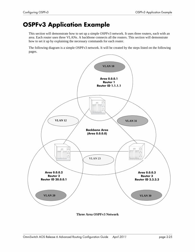
Configuring OSPFv3 OSPFv3 Application Example
OSPFv3 Application ExampleThis section will demonstrate how to set up a simple OSPFv3 network. It uses three routers, each with an area. Each router uses three VLANs. A backbone connects all the routers. This section will demonstrate how to set it up by explaining the necessary commands for each router.
The following diagram is a simple OSPFv3 network. It will be created by the steps listed on the following pages.
Three Area OSPFv3 Network
Backbone Area(Area 0.0.0.0)
Area 0.0.0.1Router 1
Router ID 1.1.1.1
Area 0.0.0.2Router 2
Router ID 20.0.0.1
Area 0.0.0.3Router 3
Router ID 3.3.3.3
VLAN 10
VLAN 20
VLAN 12
VLAN 30
VLAN 23
VLAN 31
OmniSwitch AOS Release 6 Advanced Routing Configuration Guide April 2011 page 2-25
OSPFv3 Application Example Configuring OSPFv3
Step 1: Prepare the RoutersThe first step is to create the VLANs on each router, add an IP interface to the VLAN, assign a port to the VLAN, and assign a router identification number to the routers. For the backbone, the network design in this case uses slot 2, port 1 as the egress port and slot 2, port 2 as ingress port on each router. Router 1 connects to Router 2, Router 2 connects to Router 3, and Router 3 connects to Router 1 using 10/100 Ethernet cables.
Note. The ports will be statically assigned to the router, as a VLAN must have a physical port assigned to it in order for the router port to function. However, the router could be set up in such a way that mobile ports are dynamically assigned to VLANs using VLAN rules. See the chapter titled “Defining VLAN Rules” in the see the OmniSwitch AOS Release 6 Network Configuration Guide.
The commands setting up VLANs are shown below:
Router 1 (using ports 2/1 and 2/2 for the backbone, and ports 2/3-5 for end devices):
-> vlan 31-> ipv6 interface vlan-31 vlan 31-> ipv6 address 2001:1::1/64 vlan-31-> vlan 31 port default 2/1
-> vlan 12-> ipv6 interface vlan-12 vlan 12-> ipv6 address 2001:2::1/64 vlan-12 -> vlan 12 port default 2/2
-> vlan 10-> ipv6 interface vlan-10 vlan 10-> ipv6 address 2001:3::1/64 vlan-10 -> vlan 10 port default 2/3-5
-> ip router router-id 1.1.1.1
These commands created VLANs 31, 12, and 10.
• VLAN 31 handles the backbone connection from Router 1 to Router 3, using the IP router port 2001:1::1/64 and physical port 2/1.
• VLAN 12 handles the backbone connection from Router 1 to Router 2, using the IP router port 2001:2::1/64 and physical port 2/2.
• VLAN 10 handles the device connections to Router 1, using the IP router port 2001:3::1/64 and physical ports 2/3-5. More ports could be added at a later time if necessary.
The router was assigned the Router ID of 1.1.1.1.
Router 2 (using ports 2/1 and 2/2 for the backbone, and ports 2/3-5 for end devices):
-> vlan 12-> ipv6 interface vlan-12 vlan 12-> ipv6 address 2001:2::2/64 vlan-12-> vlan 12 port default 2/1
-> vlan 23-> ipv6 interface vlan-23 vlan 23 -> ipv6 address 2001:5::1/64 vlan-23-> vlan 23 port default 2/2
page 2-26 OmniSwitch AOS Release 6 Advanced Routing Configuration Guide April 2011
Configuring OSPFv3 OSPFv3 Application Example
-> vlan 20-> ipv6 interface vlan-20 vlan 20 -> ipv6 address 2001:4::1/64 vlan-20-> vlan 20 port default 2/3-5
-> ipv6 router router-id 2.2.2.2
These commands created VLANs 12, 23, and 20.
• VLAN 12 handles the backbone connection from Router 1 to Router 2, using the IP router port 2001:2::2/64 and physical port 2/1.
• VLAN 23 handles the backbone connection from Router 2 to Router 3, using the IP router port 2001:5::1/64 and physical port 2/2.
• VLAN 20 handles the device connections to Router 2, using the IP router port 2001:4::1/64 and physical ports 2/3-5. More ports could be added at a later time if necessary.
The router was assigned the Router ID of 2.2.2.2.
Router 3 (using ports 2/1 and 2/2 for the backbone, and ports 2/3-5 for end devices):
-> vlan 23-> ipv6 interface vlan-23 vlan 23-> ipv6 address 2001:5::2/64 vlan-23-> vlan 23 port default 2/1
-> vlan 31-> ipv6 interface vlan-31 vlan 31 -> ipv6 address 2001:1::2/64 vlan-31-> vlan 31 port default 2/2
-> vlan 30-> ipv6 interface vlan-30 vlan 30 -> ipv6 address 2001:6::2/64 vlan-30-> vlan 30 port default 2/3-5
-> ipv6 router router-id 3.3.3.3
These commands created VLANs 23, 31, and 30.
• VLAN 23 handles the backbone connection from Router 2 to Router 3, using the IP router port 2001:5::2/64 and physical port 2/1.
• VLAN 31 handles the backbone connection from Router 3 to Router 1, using the IP router port 2001:1::2/64 and physical port 2/2.
• VLAN 30 handles the device connections to Router 3, using the IP router port 2001:6::2/64 and physical ports 2/3-5. More ports could be added at a later time if necessary.
The router was assigned the Router ID of 3.3.3.3.
Step 2: Load OSPFv3The next step is to load OSPFv3 on each router. The commands for this step are below (the commands are the same on each router):
-> ipv6 load ospf
OmniSwitch AOS Release 6 Advanced Routing Configuration Guide April 2011 page 2-27
OSPFv3 Application Example Configuring OSPFv3
Step 3: Create the Areas and BackboneNow the areas should be created. In this case, we will create an area for each router, and a backbone (area 0.0.0.0) that connects the areas.
The commands for this step are below:
Router 1
-> ipv6 ospf area 0.0.0.0-> ipv6 ospf area 0.0.0.1
These commands created and enabled area 0.0.0.0 (the backbone) and area 0.0.0.1 (the area for Router 1).
Router 2
-> ipv6 ospf area 0.0.0.0-> ipv6 ospf area 0.0.0.2
These commands created and enabled Area 0.0.0.0 (the backbone) and Area 0.0.0.2 (the area for Router 2).
Router 3
-> ipv6 ospf area 0.0.0.0-> ipv6 ospf area 0.0.0.3
These commands created and enabled Area 0.0.0.0 (the backbone) and Area 0.0.0.3 (the area for Router 3).
Step 4: Create, Enable, and Assign Interfaces
Next, OSPFv3 interfaces must be created, enabled, and assigned to the areas. The OSPFv3 interfaces should have the same interface name as the IPv6 router interfaces created above in “Step 1: Prepare the Routers” on page 2-26.
Router 1
-> ipv6 ospf interface vlan-31 area 0.0.0.0
-> ipv6 ospf interface vlan-12 area 0.0.0.0
-> ipv6 ospf interface vlan-10 area 0.0.0.1
IPv6 router interface vlan-31 was associated with OSPFv3 interface vlan-31, enabled, and assigned to the backbone. IPv6 router interface vlan-12 was associated with OSPFv3 interface vlan-12, enabled, and assigned to the backbone. IPv6 router interface vlan-10, which connects to end stations and attached network devices, was associated with OSPFv3 interface vlan-10, enabled, and assigned to Area 0.0.0.1.
Router 2
-> ipv6 ospf interface vlan-12 area 0.0.0.0
-> ipv6 ospf interface vlan-23 area 0.0.0.0
-> ipv6 ospf interface vlan-20 area 0.0.0.2
IPv6 router interface vlan-12 was associated with OSPFv3 interface vlan-12, enabled, and assigned to the backbone. IPv6 router interface vlan-23 was associated with OSPFv3 interface vlan-23, enabled, and assigned to the backbone. IPv6 router interface vlan-20, which connects to end stations and attached network devices, was associated with OSPFv3 interface vlan-20, enabled, and assigned to Area 0.0.0.2.
page 2-28 OmniSwitch AOS Release 6 Advanced Routing Configuration Guide April 2011
Configuring OSPFv3 OSPFv3 Application Example
Router 3
-> ipv6 ospf interface vlan-23 area 0.0.0.0
-> ipv6 ospf interface vlan-31 area 0.0.0.0
-> ipv6 ospf interface vlan-30 area 0.0.0.3
IPv6 router interface vlan-23 was associated with OSPFv3 interface vlan-23, enabled, and assigned to the backbone. IPv6 router interface vlan-31 was associated with OSPFv3 interface vlan-31, enabled, and assigned to the backbone. IPv6 router interface vlan-30, which connects to end stations and attached network devices, was associated with OSPFv3 interface vlan-30, enabled, and assigned to Area 0.0.0.3.
Step 5: Examine the NetworkAfter the network has been created, you can check the various aspects using show commands:
• For OSPFv3 in general, use the show ipv6 ospf command.
• For areas, use the show ipv6 ospf area command.
• For interfaces, use the show ipv6 ospf interface command.
• To check for adjacencies formed with neighbors, use the show ipv6 ospf neighbor command.
• For routes, use the show ipv6 ospf routes command.
OmniSwitch AOS Release 6 Advanced Routing Configuration Guide April 2011 page 2-29
Verifying OSPFv3 Configuration Configuring OSPFv3
Verifying OSPFv3 ConfigurationTo display information about areas, interfaces, virtual links, redistribution, or OPSFv3 in general, use the show commands listed in the following table:
For more information about the resulting displays from these commands, see the “OSPFv3 Commands” chapter in the OmniSwitch CLI Reference Guide.
Examples of the show ipv6 ospf, show ipv6 ospf area, and show ipv6 ospf interface command outputs are given in the section “OSPFv3 Quick Steps” on page 2-4.
show ipv6 ospf Displays the OSPFv3 status and general configuration parameters.show ipv6 redist Displays the route map redistribution configuration.show ipv6 ospf border-routers Displays information regarding all or specified border routers.show ipv6 ospf host Displays information on directly attached hosts.show ipv6 ospf lsdb Displays LSAs in the LSDB associated with each area.show ipv6 ospf neighbor Displays information on OSPFv3 non-virtual neighbors.show ipv6 ospf routes Displays the OSPFv3 routes known to the router.show ipv6 ospf virtual-link Displays virtual link information.show ipv6 ospf area Displays either all OSPFv3 areas, or a specified OSPFv3 area.show ipv6 ospf interface Displays OSPFv3 interface information.
page 2-30 OmniSwitch AOS Release 6 Advanced Routing Configuration Guide April 2011
3 Configuring IS-IS
Intermediate System-to-Intermediate System (IS-IS) is an International Organization for Standardization (ISO) dynamic routing specification.
IS-IS is a shortest path first (SPF), or link state protocol. It is an interior gateway protocol (IGP) that distributes routing information between routers in a single Autonomous System (AS) in IP as well as in OSI environments. IS-IS chooses the least-cost path as the best path. IS-IS is suitable for complex networks with large number of routers since it provides faster convergence where multiple flows to a single destination can be forwarded through one or more interfaces simultaneously.
IS-IS is also an ISO Connectionless Network Protocol (CLNP). It communicates with its peers using the Connectionless Mode Network Service (CLNS) PDU packets, which means that even in an IP-only envi-ronment the IS-IS router must have an ISO address. ISO network-layer addressing is done through Network Service Access Point (NSAP) addresses that identify any system in the OSI network.
In This ChapterThis chapter describes the basic components of IS-IS and how to configure them through the Command Line Interface (CLI). CLI commands are used in the configuration examples; for more details about the syntax of commands, refer the OmniSwitch CLI Reference Guide.
The configuration procedures described in this chapter include:
• Loading and enabling IS-IS (see page 3-15).
• Creating IS-IS areas (see page 3-15).
• Creating IS-IS interfaces (see page 3-16).
• Enabling IS-IS authentication (see page 3-18).
• Creating redistribution policies using route maps (see page 3-22).
For information on creating and managing VLANs, see “Configuring VLANs” in the see the OmniSwitch AOS Release 6 Network Configuration Guide.
OmniSwitch AOS Release 6 Advanced Routing Configuration Guide April 2011 page 3-1
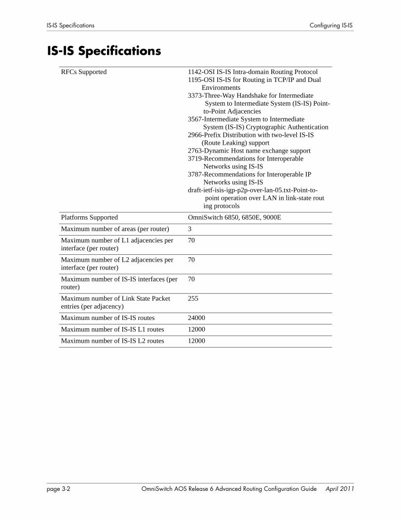
IS-IS Specifications Configuring IS-IS
IS-IS SpecificationsRFCs Supported 1142-OSI IS-IS Intra-domain Routing Protocol
1195-OSI IS-IS for Routing in TCP/IP and Dual Environments3373-Three-Way Handshake for Intermediate System to Intermediate System (IS-IS) Point- to-Point Adjacencies 3567-Intermediate System to Intermediate System (IS-IS) Cryptographic Authentication 2966-Prefix Distribution with two-level IS-IS (Route Leaking) support 2763-Dynamic Host name exchange support3719-Recommendations for Interoperable Networks using IS-IS 3787-Recommendations for Interoperable IP Networks using IS-ISdraft-ietf-isis-igp-p2p-over-lan-05.txt-Point-to- point operation over LAN in link-state rout ing protocols
Platforms Supported OmniSwitch 6850, 6850E, 9000E
Maximum number of areas (per router) 3
Maximum number of L1 adjacencies per interface (per router)
70
Maximum number of L2 adjacencies per interface (per router)
70
Maximum number of IS-IS interfaces (per router)
70
Maximum number of Link State Packet entries (per adjacency)
255
Maximum number of IS-IS routes 24000
Maximum number of IS-IS L1 routes 12000
Maximum number of IS-IS L2 routes 12000
page 3-2 OmniSwitch AOS Release 6 Advanced Routing Configuration Guide April 2011
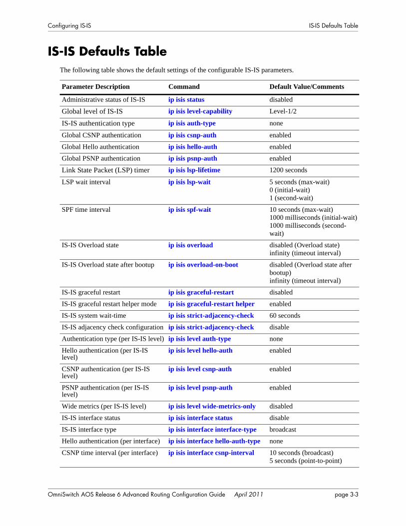
Configuring IS-IS IS-IS Defaults Table
IS-IS Defaults TableThe following table shows the default settings of the configurable IS-IS parameters.
Parameter Description Command Default Value/Comments
Administrative status of IS-IS ip isis status disabled
Global level of IS-IS ip isis level-capability Level-1/2
IS-IS authentication type ip isis auth-type none
Global CSNP authentication ip isis csnp-auth enabled
Global Hello authentication ip isis hello-auth enabled
Global PSNP authentication ip isis psnp-auth enabled
Link State Packet (LSP) timer ip isis lsp-lifetime 1200 seconds
LSP wait interval ip isis lsp-wait 5 seconds (max-wait)0 (initial-wait)1 (second-wait)
SPF time interval ip isis spf-wait 10 seconds (max-wait)1000 milliseconds (initial-wait)1000 milliseconds (second-wait)
IS-IS Overload state ip isis overload disabled (Overload state)infinity (timeout interval)
IS-IS Overload state after bootup ip isis overload-on-boot disabled (Overload state after bootup)infinity (timeout interval)
IS-IS graceful restart ip isis graceful-restart disabled
IS-IS graceful restart helper mode ip isis graceful-restart helper enabled
IS-IS system wait-time ip isis strict-adjacency-check 60 seconds
IS-IS adjacency check configuration ip isis strict-adjacency-check disable
Authentication type (per IS-IS level) ip isis level auth-type none
Hello authentication (per IS-IS level)
ip isis level hello-auth enabled
CSNP authentication (per IS-IS level)
ip isis level csnp-auth enabled
PSNP authentication (per IS-IS level)
ip isis level psnp-auth enabled
Wide metrics (per IS-IS level) ip isis level wide-metrics-only disabled
IS-IS interface status ip isis interface status disable
IS-IS interface type ip isis interface interface-type broadcast
Hello authentication (per interface) ip isis interface hello-auth-type none
CSNP time interval (per interface) ip isis interface csnp-interval 10 seconds (broadcast)5 seconds (point-to-point)
OmniSwitch AOS Release 6 Advanced Routing Configuration Guide April 2011 page 3-3
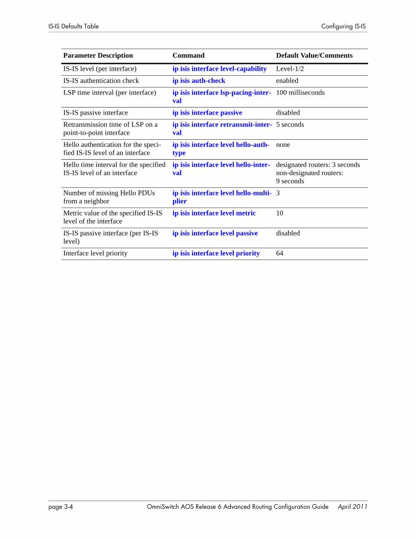
IS-IS Defaults Table Configuring IS-IS
IS-IS level (per interface) ip isis interface level-capability Level-1/2
IS-IS authentication check ip isis auth-check enabled
LSP time interval (per interface) ip isis interface lsp-pacing-inter-val
100 milliseconds
IS-IS passive interface ip isis interface passive disabled
Retransmission time of LSP on a point-to-point interface
ip isis interface retransmit-inter-val
5 seconds
Hello authentication for the speci-fied IS-IS level of an interface
ip isis interface level hello-auth-type
none
Hello time interval for the specified IS-IS level of an interface
ip isis interface level hello-inter-val
designated routers: 3 secondsnon-designated routers:9 seconds
Number of missing Hello PDUs from a neighbor
ip isis interface level hello-multi-plier
3
Metric value of the specified IS-IS level of the interface
ip isis interface level metric 10
IS-IS passive interface (per IS-IS level)
ip isis interface level passive disabled
Interface level priority ip isis interface level priority 64
Parameter Description Command Default Value/Comments
page 3-4 OmniSwitch AOS Release 6 Advanced Routing Configuration Guide April 2011
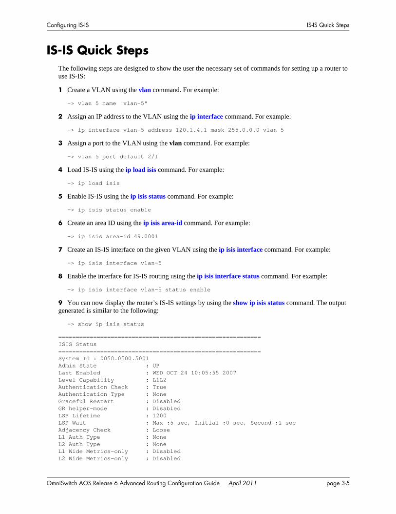
Configuring IS-IS IS-IS Quick Steps
IS-IS Quick StepsThe following steps are designed to show the user the necessary set of commands for setting up a router to use IS-IS:
1 Create a VLAN using the vlan command. For example:
-> vlan 5 name "vlan-5"
2 Assign an IP address to the VLAN using the ip interface command. For example:
-> ip interface vlan-5 address 120.1.4.1 mask 255.0.0.0 vlan 5
3 Assign a port to the VLAN using the vlan command. For example:
-> vlan 5 port default 2/1
4 Load IS-IS using the ip load isis command. For example:
-> ip load isis
5 Enable IS-IS using the ip isis status command. For example:
-> ip isis status enable
6 Create an area ID using the ip isis area-id command. For example:
-> ip isis area-id 49.0001
7 Create an IS-IS interface on the given VLAN using the ip isis interface command. For example:
-> ip isis interface vlan-5
8 Enable the interface for IS-IS routing using the ip isis interface status command. For example:
-> ip isis interface vlan-5 status enable
9 You can now display the router’s IS-IS settings by using the show ip isis status command. The output generated is similar to the following:
-> show ip isis status
==========================================================ISIS Status==========================================================System Id : 0050.0500.5001Admin State : UPLast Enabled : WED OCT 24 10:05:55 2007Level Capability : L1L2Authentication Check : TrueAuthentication Type : NoneGraceful Restart : DisabledGR helper-mode : DisabledLSP Lifetime : 1200LSP Wait : Max :5 sec, Initial :0 sec, Second :1 secAdjacency Check : LooseL1 Auth Type : NoneL2 Auth Type : NoneL1 Wide Metrics-only : DisabledL2 Wide Metrics-only : Disabled
OmniSwitch AOS Release 6 Advanced Routing Configuration Guide April 2011 page 3-5
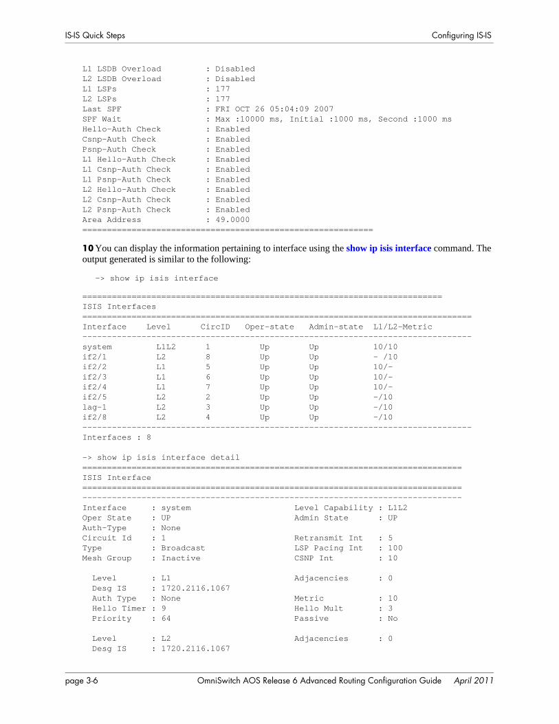
IS-IS Quick Steps Configuring IS-IS
L1 LSDB Overload : DisabledL2 LSDB Overload : DisabledL1 LSPs : 177L2 LSPs : 177Last SPF : FRI OCT 26 05:04:09 2007SPF Wait : Max :10000 ms, Initial :1000 ms, Second :1000 msHello-Auth Check : EnabledCsnp-Auth Check : EnabledPsnp-Auth Check : EnabledL1 Hello-Auth Check : EnabledL1 Csnp-Auth Check : EnabledL1 Psnp-Auth Check : EnabledL2 Hello-Auth Check : EnabledL2 Csnp-Auth Check : EnabledL2 Psnp-Auth Check : EnabledArea Address : 49.0000===========================================================
10 You can display the information pertaining to interface using the show ip isis interface command. The output generated is similar to the following:
-> show ip isis interface
=========================================================================ISIS Interfaces===============================================================================Interface Level CircID Oper-state Admin-state L1/L2-Metric-------------------------------------------------------------------------------system L1L2 1 Up Up 10/10if2/1 L2 8 Up Up - /10if2/2 L1 5 Up Up 10/-if2/3 L1 6 Up Up 10/-if2/4 L1 7 Up Up 10/-if2/5 L2 2 Up Up -/10lag-1 L2 3 Up Up -/10if2/8 L2 4 Up Up -/10-------------------------------------------------------------------------------Interfaces : 8
-> show ip isis interface detail=============================================================================ISIS Interface=============================================================================-----------------------------------------------------------------------------Interface : system Level Capability : L1L2Oper State : UP Admin State : UPAuth-Type : NoneCircuit Id : 1 Retransmit Int : 5Type : Broadcast LSP Pacing Int : 100Mesh Group : Inactive CSNP Int : 10
Level : L1 Adjacencies : 0 Desg IS : 1720.2116.1067 Auth Type : None Metric : 10 Hello Timer : 9 Hello Mult : 3 Priority : 64 Passive : No
Level : L2 Adjacencies : 0 Desg IS : 1720.2116.1067
page 3-6 OmniSwitch AOS Release 6 Advanced Routing Configuration Guide April 2011
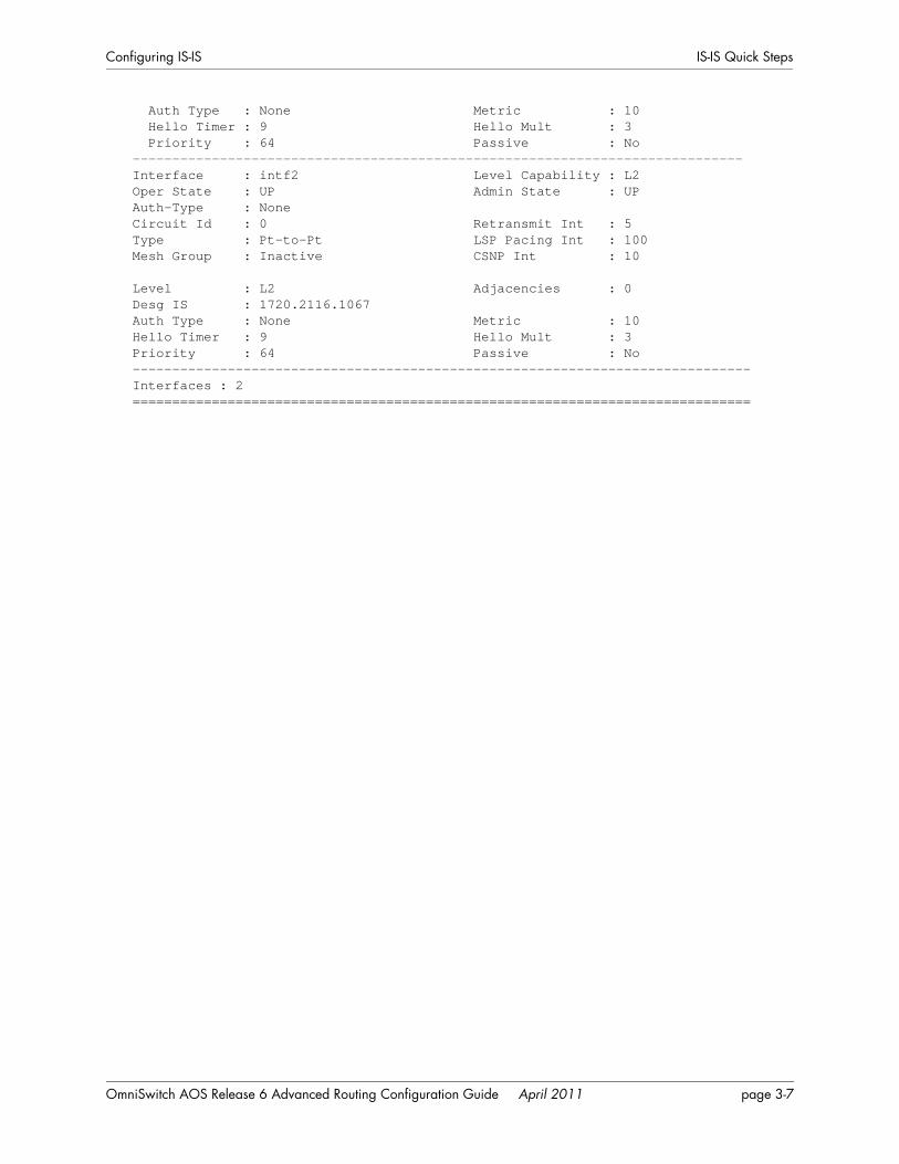
Configuring IS-IS IS-IS Quick Steps
Auth Type : None Metric : 10 Hello Timer : 9 Hello Mult : 3 Priority : 64 Passive : No-----------------------------------------------------------------------------Interface : intf2 Level Capability : L2Oper State : UP Admin State : UPAuth-Type : NoneCircuit Id : 0 Retransmit Int : 5Type : Pt-to-Pt LSP Pacing Int : 100Mesh Group : Inactive CSNP Int : 10
Level : L2 Adjacencies : 0Desg IS : 1720.2116.1067Auth Type : None Metric : 10Hello Timer : 9 Hello Mult : 3Priority : 64 Passive : No------------------------------------------------------------------------------Interfaces : 2==============================================================================
OmniSwitch AOS Release 6 Advanced Routing Configuration Guide April 2011 page 3-7

IS-IS Overview Configuring IS-IS
IS-IS OverviewIS-IS is an SPF or link state protocol. IS-IS is also an IGP that distributes routing information between routers in a single AS. It supports pure IP and OSI environments, as well as dual environments (both IP and OSI). However, it is deployed extensively in IP-only environments.
IS-IS uses a two-level hierarchy to support large routing domains. A large routing domain may be admin-istratively divided into areas, with each router residing in exactly one area. Routing within an area is referred to as Level-1 routing. A Level-1 Intermediate System (IS) keeps track of routing within its own area. Routing between areas is referred to as Level-2 routing. A Level-2 IS keeps track of paths to destina-tion areas.
IS-IS identifies a device in the network by the NSAP address. NSAP address is a logical point between network and transport layers. It consists of the following three fields:
• NSEL field—The N-Selector (NSEL) field is the last byte and it must be specified as a single byte with two hex digits preceded by a period (.). Normally, the NSEL value is set to 00.The NSAP address with its NSEL set to 00 is called Network Entity Title (NET). A NET implies the network layer address of IS-IS.
• System ID— This ID occupies the 6 bytes preceding the NSEL field. It is customary to use either a MAC address from the router (for Integrated IS-IS) or an IP address (for example, the IP address of a loopback interface) as part of the system ID.
• Area ID—The area ID occupies the rest of NSAP address.
When a router starts, it uses the IS-IS Hello protocol to discover neighbors and establish adjacencies. The router sends Hello packets through all IS-IS-enabled interfaces to its neighbors, and in turn receives Hello packets. In a broadcast network, the Hello protocol elects a Designated Intermediate System (DIS) for the network.
IS-IS Hello Protocol
Separate DISs are elected for Level-1 and Level-2 routing. Election of the DIS is based on the highest interface priority, the default value of which is 64. Priority can also be manually configured, the range being 1–127. In case of a tie, the router with the highest Subnetwork Point Of Attachment (SNPA) address (usually the MAC address) for that interface is elected as the DIS.
Routers that share common data links will become IS-IS neighbors if their Hello packets contain data that meet the requirements for forming an adjacency. The requirements may differ slightly depending on the type of media being used, which is either point-to-point or broadcast. The primary criteria for forming adjacencies are authentication match, IS-type, and MTU size.
Hello. Please respond...Are you a neighbor...
Hello. Please respond...Are you a neighbor...
My link state is... My link state is...
page 3-8 OmniSwitch AOS Release 6 Advanced Routing Configuration Guide April 2011
Configuring IS-IS IS-IS Overview
Adjacencies control the distribution of routing protocol packets. Routing protocol packets are sent and received only on adjacencies. In particular, distribution of topological database updates proceeds along adjacencies.
After establishing adjacencies, routers will build a link-state packet (LSP) based upon their local inter-faces that are configured for IS-IS and prefixes learned from other adjacent routers. Routers flood LSPs to all adjacent neighbors except the neighbor from which they received the same LSP. Routers construct their link-state database from these packets.
The link state is also advertised when a router’s state changes. A router’s adjacencies are reflected in the contents of its link state packets. This relationship between adjacencies and link state allows the protocol to detect downed routers in a timely fashion.
Link state packets are flooded throughout the AS. The flooding algorithm ensures that all routers have exactly the same topological database. This database consists of a collection of link state packets received from each router belonging to the area. From this database, each router calculates the shortest-path tree, with itself as the root. This shortest-path tree, in turn, yields a routing table for the protocol.
OmniSwitch AOS Release 6 Advanced Routing Configuration Guide April 2011 page 3-9
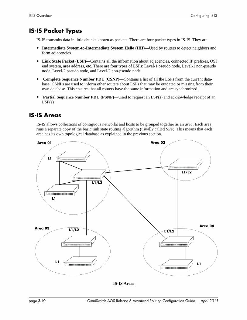
IS-IS Overview Configuring IS-IS
IS-IS Packet TypesIS-IS transmits data in little chunks known as packets. There are four packet types in IS-IS. They are:
• Intermediate System-to-Intermediate System Hello (IIH)—Used by routers to detect neighbors and form adjacencies.
• Link State Packet (LSP)—Contains all the information about adjacencies, connected IP prefixes, OSI end system, area address, etc. There are four types of LSPs: Level-1 pseudo node, Level-1 non-pseudo node, Level-2 pseudo node, and Level-2 non-pseudo node.
• Complete Sequence Number PDU (CSNP)—Contains a list of all the LSPs from the current data-base. CSNPs are used to inform other routers about LSPs that may be outdated or missing from their own database. This ensures that all routers have the same information and are synchronized.
• Partial Sequence Number PDU (PSNP)—Used to request an LSP(s) and acknowledge receipt of an LSP(s).
IS-IS AreasIS-IS allows collections of contiguous networks and hosts to be grouped together as an area. Each area runs a separate copy of the basic link state routing algorithm (usually called SPF). This means that each area has its own topological database as explained in the previous section.
IS-IS Areas
Area 01
Area 03Area 04
Area 02
L1
L1
L1 L1
L1/L2
L1/L2
L1/L2
L1/L2
page 3-10 OmniSwitch AOS Release 6 Advanced Routing Configuration Guide April 2011
Configuring IS-IS IS-IS Overview
An area’s topology is visible only to the members of that area. Routers inside a given area do not know the detailed topology outside the area. This isolation of knowledge enables the protocol to reduce routing traf-fic by concentrating on small areas of an AS, as compared to treating the entire AS as a single link state domain. In IS-IS, the router belongs entirely to a single area.
When an AS is split into IS-IS areas, the routers are classified into the following three categories:
• Level-1 routers—These are Intra-area routers and form relationship with other Level-1 or Level-1/2 routers within the same area.
• Level-1/2 routers—These routers form relationship with other Level-1, Level-2, or Level-1/2 routers. They are used to connect Inter-area routers with Intra-area routers.
• Level-2 routers—These are Inter-area routers and form relationship with other Level-2 or Level-1/2 routers
These Level capabilities can be defined globally on a router or on specific interfaces. Since a separate copy of the link state algorithm is run in each area, most configuration parameters are defined on a per-router basis. All routers belonging to an area must agree on that area’s configuration. Misconfiguration will keep neighbors from forming adjacencies between themselves, and IS-IS will not function.
OmniSwitch AOS Release 6 Advanced Routing Configuration Guide April 2011 page 3-11
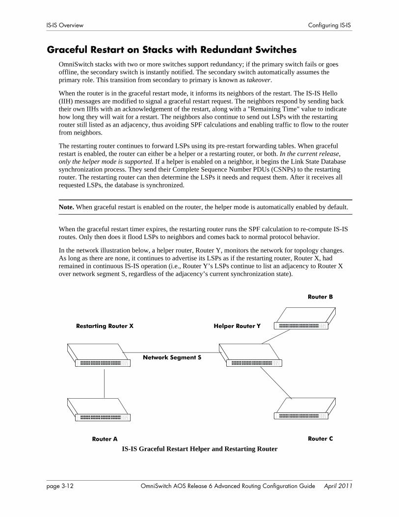
IS-IS Overview Configuring IS-IS
Graceful Restart on Stacks with Redundant SwitchesOmniSwitch stacks with two or more switches support redundancy; if the primary switch fails or goes offline, the secondary switch is instantly notified. The secondary switch automatically assumes the primary role. This transition from secondary to primary is known as takeover.
When the router is in the graceful restart mode, it informs its neighbors of the restart. The IS-IS Hello (IIH) messages are modified to signal a graceful restart request. The neighbors respond by sending back their own IIHs with an acknowledgement of the restart, along with a "Remaining Time" value to indicate how long they will wait for a restart. The neighbors also continue to send out LSPs with the restarting router still listed as an adjacency, thus avoiding SPF calculations and enabling traffic to flow to the router from neighbors.
The restarting router continues to forward LSPs using its pre-restart forwarding tables. When graceful restart is enabled, the router can either be a helper or a restarting router, or both. In the current release, only the helper mode is supported. If a helper is enabled on a neighbor, it begins the Link State Database synchronization process. They send their Complete Sequence Number PDUs (CSNPs) to the restarting router. The restarting router can then determine the LSPs it needs and request them. After it receives all requested LSPs, the database is synchronized.
Note. When graceful restart is enabled on the router, the helper mode is automatically enabled by default.
When the graceful restart timer expires, the restarting router runs the SPF calculation to re-compute IS-IS routes. Only then does it flood LSPs to neighbors and comes back to normal protocol behavior.
In the network illustration below, a helper router, Router Y, monitors the network for topology changes. As long as there are none, it continues to advertise its LSPs as if the restarting router, Router X, had remained in continuous IS-IS operation (i.e., Router Y’s LSPs continue to list an adjacency to Router X over network segment S, regardless of the adjacency’s current synchronization state).
IS-IS Graceful Restart Helper and Restarting Router
Restarting Router X
Network Segment S
Helper Router Y
Router A
Router B
Router C
page 3-12 OmniSwitch AOS Release 6 Advanced Routing Configuration Guide April 2011

Configuring IS-IS IS-IS Overview
If the restarting router, Router X, is identified as the Designated Router (DIS) on the network segment S at the beginning of the helping relationship, the helper neighbor, Router Y, will maintain Router X as the DIS until the helping relationship is terminated. If there are multiple adjacencies with the restarting Router X, Router Y will act as a helper on all other adjacencies.
OmniSwitch AOS Release 6 Advanced Routing Configuration Guide April 2011 page 3-13
Configuring IS-IS Configuring IS-IS
Configuring IS-ISConfiguring IS-IS on a router requires several steps. Depending on your requirements, you may need to perform all the steps listed below.
By default, IS-IS is disabled on the router. Configuring IS-IS consists of the following tasks:
• Set up the basics of the IS-IS network by configuring the required VLANs and assigning ports to the VLANs. This is described in “Preparing the Network for IS-IS” on page 3-14.
• Enable IS-IS. When the image file for advanced routing is installed, you must load the code and enable IS-IS. The commands for enabling IS-IS are described in “Activating IS-IS” on page 3-15.
• Configure an IS-IS area ID. The commands to create areas and backbones are described in “Creating an IS-IS Area ID” on page 3-15.
• Create IS-IS interfaces. IS-IS interfaces are created and assigned to areas. Creating interfaces is described in “Creating an Interface” on page 3-16.
• Configure IS-IS levels. Routers are configured at different IS-IS levels. This is described in “Configuring the IS-IS Level” on page 3-16.
• Enable summarization. Routes can be summarized on routers. This is described in “Enabling Summarization” on page 3-18.
• Configure IS-IS authentication (optional). This is described in “Enabling IS-IS Authentication” on page 3-18.
• Configure interface level parameters (optional). The commands to configure interface level parameters are described in “Modifying Interface Parameters” on page 3-21.
• Create a redistribution policy and enable the same using route maps (optional). To create route maps, see “Configuring Redistribution Using Route Maps” on page 3-22.
• Configure router capabilities (optional). There are several commands that influence router operation. These are covered briefly in the table in “Configuring Router Capabilities” on page 3-28.
• Configure redundant switches for graceful IS-IS restart (optional). Configuring switches with redun-dant switches for graceful restart is described in “Configuring Redundant Switches in a Stack for Graceful Restart” on page 3-28.
At the end of the chapter is a simple IS-IS network diagram with instructions on how it was created on a router-by-router basis. See “IS-IS Application Example” on page 3-29 for more information.
Preparing the Network for IS-ISIS-IS operates over normal switch functions, using existing ports, virtual ports, VLANs, etc. However, the following network components should already be configured:
• Configure VLANs that are to be used in the IS-IS network. VLANs should be created for all the connected devices that will participate in the IS-IS network. VLAN configuration is described in “Configuring VLANs” in the OmniSwitch AOS Release 6 Network Configuration Guide.
• Assign IP interfaces to the VLANs. IP interfaces or router ports, must be assigned to the VLAN. Assigning IP interfaces is described in “Configuring IP” in the OmniSwitch AOS Release 6 Network Configuration Guide.
page 3-14 OmniSwitch AOS Release 6 Advanced Routing Configuration Guide April 2011
Configuring IS-IS Configuring IS-IS
• Assign ports to the VLANs. The physical ports participating in the IS-IS network must be assigned to the created VLANs. Assigning ports to a VLAN is described in “Assigning Ports to VLANs” in the OmniSwitch AOS Release 6 Network Configuration Guide.
• Set the area ID (optional). The routers participating in the IS-IS network must be assigned an area identification number. The area ID is a part of the Network Service Access Point (NSAP) address, which identifies a point of connection to the network, such as a router interface. The area identification number assignment is discussed in “Creating an IS-IS Area ID” on page 3-15.
Activating IS-ISTo run IS-IS on the router, the advanced routing image must be installed. For information on how to install image files, refer to the OmniSwitch AOS Release 6 Switch Management Guide.
After the image file has been installed onto the router, you need to load the IS-IS software into the memory and enable it, as described below:
Loading the Software
To load the IS-IS software into the router’s running configuration, enter the ip load isis command at the system prompt:
-> ip load isis
The IS-IS software is now loaded into the memory, and can be enabled. IS-IS is not loaded on the switch by default.
Enabling IS-IS
Once the IS-IS software has been loaded into the router’s running configuration (either through the CLI or on startup), it must be enabled. To enable IS-IS on a router, enter the ip isis status command at the CLI prompt, as shown:
-> ip isis status enable
Once IS-IS is enabled, you can begin to set up IS-IS parameters. To disable IS-IS, enter the following:
-> ip isis status disable
Removing IS-IS
To remove IS-IS from the router memory, it is necessary to manually edit the boot.cfg file. The boot.cfg file is an ASCII text-based file that controls many of the switch parameters. Open the file and delete all references to IS-IS.
For the operation to take effect the switch needs to be rebooted.
Creating an IS-IS Area IDIS-IS allows a set of network devices in an AS to be grouped together in areas. Each area is identified by an area ID. The area ID is a 1–13 byte variable length integer, which specifies the area address of an IS-IS routing process.
For creating an IS-IS area first assign area ID to each router present in the network by using the ip isis area-id command. There can be more than one router in an area.
OmniSwitch AOS Release 6 Advanced Routing Configuration Guide April 2011 page 3-15
Configuring IS-IS Configuring IS-IS
Note: Each router can have a maximum of 3 area IDs assigned to it.
Creating an Area ID
To create an area ID and associate it with a router, enter the ip isis area-id command with the areaidentification number at the CLI prompt, as shown:
-> ip isis area-id 49.0001
Area ID 49.0001 will now be created on the router with the default parameters.
Deleting an Area ID
To delete an area ID, enter the ip isis area-id command, as shown:
-> no ip isis area-id 49.0001
Creating IS-IS InterfacesOnce areas have been created, interfaces need to be created and enabled for IS-IS routing.
Creating an Interface
To create an interface, enter the ip isis interface command with an interface name, as shown:
-> ip isis interface vlan-101
Note. The interface name cannot have spaces.
To delete an interface, use the no form of the ip isis interface, as shown:
-> no ip isis interface vlan-101
Enabling an Interface
Once an interface is created, it must be enabled using the ip isis interface status command, as shown:
-> ip isis interface vlan-101 status enable
Configuring the IS-IS LevelThe Autonomous System is divided into multiple areas to reduce the control traffic and size of routing table. To communicate within an IS-IS area, Level-1 routers are used. To communicate between areas, Level-2 routers are used. A router can be a configured to be a Level-1 router, a Level-2 router, or both.
The level capability can be configured globally on the router or on specific interfaces. By default, the router can operate at both levels.
To modify the level capability of the router globally, use the ip isis level-capability command as explained in the following examples:
To configure a router as a Level-1 router, enter:
-> ip isis level-capability level-1
page 3-16 OmniSwitch AOS Release 6 Advanced Routing Configuration Guide April 2011
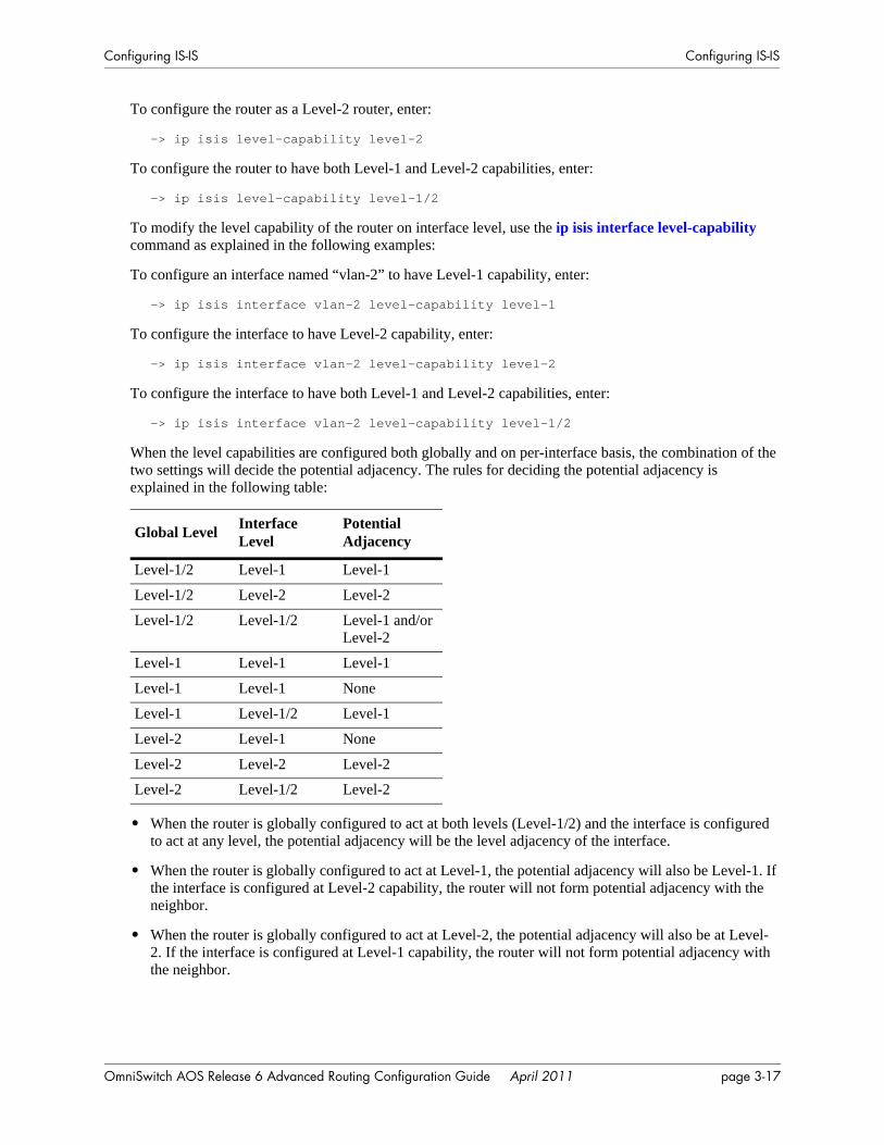
Configuring IS-IS Configuring IS-IS
To configure the router as a Level-2 router, enter:
-> ip isis level-capability level-2
To configure the router to have both Level-1 and Level-2 capabilities, enter:
-> ip isis level-capability level-1/2
To modify the level capability of the router on interface level, use the ip isis interface level-capability command as explained in the following examples:
To configure an interface named “vlan-2” to have Level-1 capability, enter:
-> ip isis interface vlan-2 level-capability level-1
To configure the interface to have Level-2 capability, enter:
-> ip isis interface vlan-2 level-capability level-2
To configure the interface to have both Level-1 and Level-2 capabilities, enter:
-> ip isis interface vlan-2 level-capability level-1/2
When the level capabilities are configured both globally and on per-interface basis, the combination of the two settings will decide the potential adjacency. The rules for deciding the potential adjacency is explained in the following table:
• When the router is globally configured to act at both levels (Level-1/2) and the interface is configured to act at any level, the potential adjacency will be the level adjacency of the interface.
• When the router is globally configured to act at Level-1, the potential adjacency will also be Level-1. If the interface is configured at Level-2 capability, the router will not form potential adjacency with the neighbor.
• When the router is globally configured to act at Level-2, the potential adjacency will also be at Level-2. If the interface is configured at Level-1 capability, the router will not form potential adjacency with the neighbor.
Global Level Interface Level
Potential Adjacency
Level-1/2 Level-1 Level-1
Level-1/2 Level-2 Level-2
Level-1/2 Level-1/2 Level-1 and/or Level-2
Level-1 Level-1 Level-1
Level-1 Level-1 None
Level-1 Level-1/2 Level-1
Level-2 Level-1 None
Level-2 Level-2 Level-2
Level-2 Level-1/2 Level-2
OmniSwitch AOS Release 6 Advanced Routing Configuration Guide April 2011 page 3-17
Configuring IS-IS Configuring IS-IS
Enabling SummarizationRoute summarization in IS-IS reduces the number of routes that a router must maintain, and represents a series of network numbers in a single summary address.
Summarization can also be enabled or disabled when creating an area. IS-IS routes can be summarized into Level-2 from the Level-1 database. It is not possible to summarize IS-IS internal routes at Level-1, although it is possible to summarize external (redistributed) routes. You can summarize level-1, level-2, level-1/2 IS-IS routes. The metric that is used to advertise the summary address is the smallest metric than any of the more specific IPv4 routes.
For example, to summarize the routes between 100.1.1.0/24 and 100.1.100.0/24 into one, enter the follow-ing command:
-> ip isis summary-address 100.1.0.0/16 level-2
To remove the summary address, enter the following:
-> no ip isis summary-address 100.1.0.0/16 level-2
Note. IS-IS routes are not summarized by default. If you do not specify the level while configuring the summarization, level-1/2 routes are summarized by default.
Displaying Summary Address
You can view the details of the IS-IS summary address using the show ip isis summary-address command:
-> show ip isis summary-address
Enabling IS-IS AuthenticationIS-IS allows for the use of authentication on a device. When authentication is enabled, only neighbors using the same type of authentication and the matching keys can communicate.
There are two types of authentication: simple and MD5. Simple authentication requires only a text string as a password, while MD5 is a form of encrypted authentication that requires a key and a password.
You can use the key parameter to configure the password for Simple or MD5 authentication. Alterna-tively, you can use the encrypt-key parameter to configure the password by supplying the encrypted form of the password as the encrypt-key. Configuration snapshot always displays the password in an encrypted form. You should use only the key parameter during the CLI configuration.
If the encrypt-key parameter is used to configure the password through the CLI, then its value should be the same as the one that appears in the configuration snapshot.
Note. By default, the authentication is disabled and no authentication type is configured
page 3-18 OmniSwitch AOS Release 6 Advanced Routing Configuration Guide April 2011
Configuring IS-IS Configuring IS-IS
Simple Authentication
Simple authentication works by including the password in the packet. This helps to protect the routers from a configuration mishap.
To enable simple authentication with plain text key on a router, enter the ip isis auth-type command, as shown:
-> ip isis auth-type simple key 12345
Here, only routers with simple authentication and simple key “12345” will be able to use the configured interface.
You can also use the encrypt-key parameter to configure the password by supplying the encrypted form of the password.
-> ip isis auth-type simple encrypt-key 31fa061a5de5d1a8
If the encrypt-key parameter is used to configure the password through the CLI, then its value should be the same as the one that appears in the configuration snapshot.
Note. Only valid system generated values are accepted as encrypt-key.
MD5 Authentication
MD5 authentication can be used to protect the system from malicious actions. MD5 authentication can be used to encrypt information sent over the network. MD5 authentication works by using shared secret key. Key is used to sign the packets with an MD5 checksum, so that the packets cannot be forged or tampered with. Since the key is not included in the packet, snooping the key is not possible.
To enable MD5 authentication with plain text key on a router, enter the ip isis auth-type command, as shown:
-> ip isis auth-type md5 key 12345
Here, only routers with MD5 authentication and password “12345” will be able to use the configured interface.
You can also use the encrypt-key parameter to configure the password by supplying the encrypted form of the password.
-> ip isis auth-type md5 encrypt-key 31fa061a5de5d1a8
If the encrypt-key parameter is used to configure the password through the CLI, then its value should be the same as the one that appears in the configuration snapshot.
Note. Only valid system generated values are accepted as encrypt-key.
Global Authentication
The authentication check for all the IS-IS PDUs can be enabled or disabled globally by using the ip isis auth-check command.
To enable the authentication check for IS-IS PDUs, enter the following:
-> ip isis auth-check enable
OmniSwitch AOS Release 6 Advanced Routing Configuration Guide April 2011 page 3-19
Configuring IS-IS Configuring IS-IS
If enabled, IS-IS PDUs that fail to match either of the authentication type and key requirements are rejected.
To disable the authentication check for IS-IS PDUs, enter the following:
-> ip isis auth-check disable
If disabled, the authentication PDUs are generated and the IS-IS PDUs are authenticated on receipt. An error message will be generated in case of a mismatch; but PDUs will not be rejected.
Note. By default, authentication check is enabled.
IS-IS authentication can be enabled globally for Hello, CSNP, and PSNP packets.
To enable the authentication of Hello PDUs globally, enter the following:
-> ip isis hello-auth
To enable the authentication of CSNP PDUs globally, enter the following:
-> ip isis csnp-auth
To enable the authentication of PSNP PDUs globally, enter the following:
-> ip isis psnp-auth
Level Authentication
You can enable authentication and configure the authentication types for specific IS-IS levels globally using ip isis level auth-type command. For example:
-> ip isis level 2 auth-type md5 encrypt-key 7a1e441a014b4030
The above example configures the authentication type as MD5 for level 2 IS-IS PDUs and the key.
Note. You can configure the authentication of either simple or MD5 type with the password specified either in plain text or in encrypted form. For the explanations about the authentication types and the key types refer Simple authentication and MD5 authentication.
IS-IS authentication can be enabled for specific IS-IS PDUs such as Hello, CSNP, and PSNP packets at specific IS-IS levels (Level-1, Level-2, or Level-1/2). Enabling authentication on specific IS-IS levels over-rides the global authentication.
To enable the authentication of Hello PDUs for IS-IS Level-1, enter the following:
-> ip isis level 1 hello-auth
To enable the authentication of CSNP PDUs for IS-IS Level-2, enter the following:
-> ip isis level 2 csnp-auth
To enable the authentication of PSNP PDUs for IS-IS Level-2, enter the following:
-> ip isis level 2 psnp-auth
page 3-20 OmniSwitch AOS Release 6 Advanced Routing Configuration Guide April 2011
Configuring IS-IS Configuring IS-IS
Interface Authentication
IS-IS authentication can be enabled for Hello packets on specific interfaces using ip isis interface hello-auth-type.
For example, to enable MD5 authentication of Hello PDUs on the interface VLAN 100, enter the follow-ing:
-> ip isis interface vlan-100 hello-auth-type md5 key 12345
IS-IS authentication can also be enabled for Hello packets at different levels on specific interfaces using ip isis interface hello-auth-type.
For example, to enable simple authentication of Hello PDUs on the interface VLAN 100 at Level-2, enter the following:
-> ip isis interface vlan-100 level 2 hello-auth-type simple encrypt-key 7a1e441a014b4030
Note. Both the ip isis interface hello-auth-type and ip isis interface level hello-auth-type can be config-ured for the authentication of either simple or MD5 type with the password specified either in plain text or in encrypted form. For the explanations about the authentication types and the key types refer Simple authentication and MD5 authentication.
Modifying Interface ParametersTo configure the interval between the successive Hello PDUs at the given IS-IS level on an interface, enter the ip isis interface level hello-interval command, as shown:
-> ip isis interface man-1 level 1 hello-interval 50
To configure the number of Hello PDUs before the router declares the adjacency as down, use the ip isis interface level hello-multiplier command, as shown:
-> ip isis interface lan-1 level 1 hello-multiplier 10
To configure the metric value of the IS-IS level of the interface, enter the ip isis interface level metric command, as shown:
-> ip isis interface interface-1 level 1 metric 25
Configuring an interface as passive suppresses IS-IS packets from being sent or received on the interface. For example, to configure the interface from receiving Level-1 IS-IS packets, enter theip isis interface level passive command, as shown:
-> ip isis interface lan-5 level 1 passive
Configuring the priority value helps to determine a DIS in a multi-access network. To configure the prior-ity of the IS-IS router interface for the election of a DIS in a multi-access network, enter the ip isis interface level priority command, as shown:
-> ip isis interface vlan-isis level 1 priority 4
There are several other interface parameters that can be modified on a specified interface. Most of these deal with timer settings.
OmniSwitch AOS Release 6 Advanced Routing Configuration Guide April 2011 page 3-21
Configuring IS-IS Configuring IS-IS
The following table shows the various interface parameters that can be set:
These parameters can be added any time. In broadcast networks, the DIS sends CSNP packets to maintain database synchronization. For example, to configure the CSNP PDUs time interval to 50 seconds, enter the following:
-> ip isis interface vlan-101 csnp-interval 50
To set the LSP interval to 120 seconds, enter the following:
-> ip isis interface vlan-101 lsp-pacing-interval 120
To set the LSP retransmit interval to 100 seconds, enter the following:
-> ip isis interface lan-3 retransmit-interval 100
Note. The retransmit interval should be greater than the expected round-trip delay between two devices.This will avoid any needless retransmission of PDUs.
Configuring Redistribution Using Route MapsIt is possible to configure the IS-IS protocol to advertise routes learned from other routing protocols (AS-external routes) into the IS-IS network. Such a process is referred to as route redistribution and is config-ured using the ip redist command.
IS-IS redistribution uses route maps to control how external routes are learned and distributed. A route map consists of one or more user-defined statements that can determine which routes are allowed or denied access to the IS-IS network. In addition a route map may also contain statements that modify route parameters before they are redistributed.
When a route map is created, it is given a name to identify the group of statements that it represents. This name is required by the ip redist command. Therefore, configuring IS-IS route redistribution involves the following steps:
1 Create a route map, as described in “Using Route Maps” on page 3-23.
2 Configure redistribution to apply a route map, as described in “Configuring Route Map Redistribu-tion” on page 3-26.
ip isis interface csnp-interval Configures the time interval in seconds to send Complete Sequence Number PDUs (CSNP) from the specified interface.
ip isis interface lsp-pacing-interval
Configures the interval between IS-IS Link State PDUs (LSP) sent from the specified interface.
ip isis interface retransmit-interval
Configures the minimum time between Link State PDU (LSP) trans-missions on a point-to-point interface.
ip isis interface default-type Configures the interface type to default (Broadcast).
page 3-22 OmniSwitch AOS Release 6 Advanced Routing Configuration Guide April 2011
Configuring IS-IS Configuring IS-IS
Using Route MapsA route map specifies the criteria that are used to control redistribution of routes between protocols. Such criteria are defined by configuring route map statements. There are three different types of statements:
• Action—An action statement configures the route map name, sequence number, and whether or not redistribution is permitted or denied based on route map criteria.
• Match—A match statement specifies criteria that a route must match. When a match occurs, then the action statement is applied to the route.
• Set—A set statement is used to modify route information before the route is redistributed into the receiving protocol. This statement is applied only if all the criteria of the route map is met and the action permits redistribution.
The ip route-map command is used to configure route map statements and provides the following action, match, and set parameters:
Note. The tag parameter is not supported in the current release.
Refer to the “IP Commands” chapter in the OmniSwitch CLI Reference Guide for more information about the ip route-map command parameters and usage guidelines.
Once a route map is created, it is then applied using the ip redist command. See “Configuring Route Map Redistribution” on page 3-26 for more information.
Creating a Route Map
When a route map is created, it is given a name (up to 20 characters), a sequence number, and an action (permit or deny). Specifying a sequence number is optional. If a value is not configured, then the number 50 is used by default.
To create a route map, use the ip route-map command with the action parameter. For example,
-> ip route-map rip-to-isis sequence-number 10 action permit
The above command creates the rip-to-isis route map, assigns a sequence number of 10 to the route map, and specifies a permit action.
To optionally filter routes before redistribution, use the ip route-map command with a match parameter to configure match criteria for incoming routes. For example,
-> ip route-map rip-to-isis sequence-number 10 match metric 8
The above command configures a match statement for the rip-to-isis route map to filter routes based on
ip route-map action ... ip route-map match ... ip route-map set ...
permitdeny
ip addressip next-hopipv6 addressipv6 next-hoptagipv4-interfaceipv6-interfacemetricroute-type
metricmetric-typetagcommunitylocal-preferencelevelip-nexthopipv6-nexthop
OmniSwitch AOS Release 6 Advanced Routing Configuration Guide April 2011 page 3-23
Configuring IS-IS Configuring IS-IS
their metric value. When this route map is applied, only RIP routes with a metric value of eight are redis-tributed into the IS-IS network. All other routes with a different metric value are dropped.
Note. Configuring match statement is not required. However, if a route map does not contain any match statement and the route map is applied using the ip redist command, the router redistributes all routes into the network of the receiving protocol.
To modify route information before it is redistributed, use the ip route-map command with a set parame-ter. For example,
-> ip route-map rip-to-isis sequence-number 10 set metric 5
The above command configures a set statement for the rip-to-isis route map that changes the metric value to five. Because this statement is part of the rip-to-isis route map, it is only applied to routes that have an existing metric value equal to eight.
The following is a summary of the commands used in the above examples:-> ip route-map rip-to-isis sequence-number 10 action permit-> ip route-map rip-to-isis sequence-number 10 match metric 8-> ip route-map rip-to-isis sequence-number 10 set metric 5
To verify a route map configuration, use the show ip route-map command:-> show ip route-mapRoute Maps: configured: 1 max: 200Route Map: rip-to-isis Sequence Number: 10 Action permit match metric 8 set metric 5
Deleting a Route Map
Use the no form of the ip route-map command to delete an entire route map, a route map sequence, or a specific statement within a sequence.
To delete an entire route map, enter no ip route-map followed by the route map name. For example, the following command deletes the entire route map named rip-to-isis:
-> no ip route-map rip-to-isis
To delete a specific sequence number within a route map, enter no ip route-map followed by the route map name, then sequence-number followed by the actual number. For example, the following command deletes sequence 10 from the rip-to-isis route map:
-> no ip route-map rip-to-isis sequence-number 10
Note that in the above example, the rip-to-isis route map is not deleted. Only those statements associated with sequence 10 are removed from the route map.
To delete a specific statement within a route map, enter no ip route-map followed by the route map name, then sequence-number followed by the sequence number for the statement, then either match or set and the match or set parameter and value. For example, the following command deletes only the match metric 8 statement from route map rip-to-isis sequence 10:
-> no ip route-map rip-to-isis sequence-number 10 match metric 8
page 3-24 OmniSwitch AOS Release 6 Advanced Routing Configuration Guide April 2011
Configuring IS-IS Configuring IS-IS
Configuring Route Map Sequences
A route map may consist of one or more sequences of statements. The sequence number determines which statements belong to which sequence and the order in which sequences for the same route map are processed.
To add match and set statements to an existing route map sequence, specify the same route map name and sequence number for each statement. For example, the following series of commands creates route map rm_1 and configures match and set statements for the rm_1 sequence 10:
-> ip route-map rm_1 sequence-number 10 action permit-> ip route-map rm_1 sequence-number 10 match metric 8-> ip route-map rm_1 sequence-number 10 set metric 2
To configure a new sequence of statements for an existing route map, specify the same route map name but use a different sequence number. For example, the following command creates a new sequence 20 for the rm_1 route map:
-> ip route-map rm_1 sequence-number 20 action permit-> ip route-map rm_1 sequence-number 20 match ipv4-interface to-finance-> ip route-map rm_1 sequence-number 20 set metric 5
The resulting route map appears as follows:-> show ip route-map rm_1Route Map: rip-to-isis Sequence Number: 10 Action permit match metric 8 set metric 2Route Map: rip-to-isis Sequence Number: 20 Action permit match ipv4 interface to-finance set metric 5
Sequence 10 and sequence 20 are both linked to route map rm_1 and are processed in ascending order according to their sequence number value. Note that there is an implied logical OR between sequences. As a result, if there is no match for the metric value in sequence 10, then the match interface statement in sequence 20 is processed. However, if a route matches the metric value 8, then sequence 20 is not used. The set statement for whichever sequence was matched is applied.
A route map sequence may contain multiple match statements. If these statements are of the same kind (e.g., match metric 5, match metric 8, etc.) then a logical OR is implied between each like statement. If the match statements specify different types of matches (e.g. match metric 8, match ip4 interface to-finance, etc.), then a logical AND is implied between each statement. For example, the following route map sequence will redistribute a route if its metric value is either 8 or 5:
-> ip route-map rm_1 sequence-number 10 action permit-> ip route-map rm_1 sequence-number 10 match metric 5-> ip route-map rm_1 sequence-number 10 match metric 8
The following route map sequence will redistribute a route if the route has a metric of 8 or 5 and if the route was learned on the IPv4 interface to-finance:
-> ip route-map rm_1 sequence-number 10 action permit-> ip route-map rm_1 sequence-number 10 match metric 5-> ip route-map rm_1 sequence-number 10 match metric 8-> ip route-map rm_1 sequence-number 10 match ipv4-interface to-finance
OmniSwitch AOS Release 6 Advanced Routing Configuration Guide April 2011 page 3-25
Configuring IS-IS Configuring IS-IS
Configuring Access Lists
An IP access list provides a convenient way to add multiple IPv4 addresses to a route map. Using an access list avoids having to enter a separate route map statement for each individual IP address. Instead, a single statement is used that specifies the access list name. The route map is then applied to all the addresses contained within the access list.
Configuring an IP access list involves two steps: creating the access list and adding IP addresses to the list. To create an IP access list, use the ip access-list and specify a name to associate with the list. For example,
-> ip access-list ipaddr
To add addresses to an access list, use the ip access-list address command. For example, the following commands add addresses to an existing access list:
-> ip access-list ipaddr address 16.24.2.1/16
Use the same access list name each time the above commands are used to add additional addresses to the same access list. In addition, both commands provide the ability to configure if an address and/or its matching subnet routes are permitted (the default) or denied redistribution. For example:
-> ip access-list ipaddr address 16.24.2.1/16 action deny redist-control all-subnets
For more information about configuring access list commands, see the “IP Commands” chapter in the OmniSwitch CLI Reference Guide.
Configuring Route Map RedistributionThe ip redist command is used to configure the redistribution of routes from a source protocol into the IS-IS destination protocol. This command is used on the IS-IS router that will perform the redistribution.
A source protocol is a protocol from which the routes are learned. A destination protocol is the one into which the routes are redistributed. Make sure that both protocols are loaded and enabled before configur-ing redistribution.
Redistribution applies criteria specified in a route map to routes received from the source protocol. There-fore, configuring redistribution requires an existing route map. For example, the following command configures the redistribution of RIP routes into the IS-IS network using the rip-to-isis route map:
-> ip redist rip into isis route-map rip-to-isis
RIP routes received by the ISIS router interface are processed based on the contents of the rip-to-isis route map. Routes that match criteria specified in this route map are either allowed or denied redistribution into the ISIS network. The route map may also specify the modification of route information before the route is redistributed. See “Using Route Maps” on page 3-23 for more information.
To remove a route map redistribution configuration, use the no form of the ip redist into isis route-map command. For example:
-> no ip redist rip into isis route-map rip-to-isis
Use the show ip redist command to verify the redistribution configuration:-> show ip redistSource DestinationProtocol Protocol Status Route Map------------+------------+---------+--------------------OSPF ISIS Enabled ospf-to-isisRIP ISIS Enabled rip-to-isis
page 3-26 OmniSwitch AOS Release 6 Advanced Routing Configuration Guide April 2011
Configuring IS-IS Configuring IS-IS
Configuring the Administrative Status of the Route Map Redistribution
The administrative status of a route map redistribution configuration is enabled by default. To change the administrative status, use the status parameter with the ip redist into isis route-map command. For example, the following command disables the redistribution administrative status for the specified route map:
-> ip redist rip into isis route-map rip-to-isis status disable
The following command example enables the administrative status:
-> ip redist rip into isis route-map rip-to-isis status enable
Route Map Redistribution ExampleThe following example configures the redistribution of RIP routes into an IS-IS network using a route map (rip-to-isis) to filter specific routes:
-> ip route-map rip-to-isis sequence-number 10 action deny -> ip route-map rip-to-isis sequence-number 10 match metric 5
-> ip route-map rip-to-isis sequence-number 20 action permit-> ip route-map rip-to-isis sequence-number 20 match ipv4-interface intf_isis-> ip route-map rip-to-isis sequence-number 20 set metric 60
-> ip route-map rip-to-isis sequence-number 30 action permit-> ip route-map rip-to-isis sequence-number 30 set metric 8-> ip redist rip into isis route-map rip-to-isis
The resulting rip-to-isis route map redistribution configuration does the following:
• Denies the redistribution of RIP routes with a metric value set to five.
• Redistributes into IS-IS all routes learned on the intf_isis interface and sets the metric for such routes to 60.
Note. Wide metrics need to be enabled, if a metric of more than 64 is configured.
• Redistributes all other routes (those not processed by sequence 10 or 20) and sets the metric for such routes to eight.
IS-IS allows redistributing Level-1 IS-IS routes into Level-2 IS-IS routes. This is termed as Level-1 to Level-2 Leaking. This release also supports the prefix distribution from the level-2 IS-IS routes to level-1 IS-IS routes.
The following example configures the IS-IS Level-1 to Level-2 Leaking routes using a route map (is2is) to filter specific routes.
To redistribute IS-IS Level-1 routes into IS-IS Level-2 routes, use the following route map sequence:
-> ip route-map is2is sequence-number 1 action permit-> ip route-map is2is sequence-number 1 match route-type level1-> ip route-map is2is sequence-number 1 set level level2-> ip redist isis into isis route-map is2is status enable
The resulting is2is route map redistribution configuration redistributes all Level-1 IS-IS routes into Level-2 IS-IS routes.
OmniSwitch AOS Release 6 Advanced Routing Configuration Guide April 2011 page 3-27
Configuring IS-IS Configuring IS-IS
Configuring Router CapabilitiesThe following table lists various commands that can be useful in tailoring a router’s performance capabili-ties. All the listed parameters have defaults that are acceptable for running an IS-IS network.
To set the IS-IS router to operate in overload state, enter:
-> ip isis overload timeout 70
To configure the router to be in the overload state, enter:
-> ip isis overload-on-boot timeout 80
To enable the adjacency check configuration, enter:
-> ip isis strict-adjacency-check enable
Configuring Redundant Switches in a Stack for Graceful RestartBy default, IS-IS graceful restart is disabled. When graceful restart is enabled, the router can either be a helper or a restarting router. When graceful restart is enabled on the router, the helper mode is automati-cally enabled by default. To configure IS-IS graceful restart support on OmniSwitch switches, use the ip isis graceful-restart command.
Note. In the current release, only the graceful restart helper mode is supported.
For example, to configure graceful restart on the router, enter:
-> ip isis graceful-restart
The helper mode can be disabled on the router with the ip isis graceful-restart helper command. For example, to disable the helper support for neighboring routers, enter the following:
-> ip isis graceful-restart helper disable
To disable support for graceful restart, use the no form of the ip isis graceful-restart command by enter-ing:
-> no ip isis graceful-restart
On OmniSwitch 6850 Series switches, continuous forwarding during a graceful restart depends on several factors. If the secondary module has a different router MAC than the primary module, or if one or more ports of a VLAN belonged to the primary module, spanning tree re-convergence might disrupt forwarding state, even though IS-IS performs a graceful restart.
Note. Graceful restart is only supported on active ports (i.e., interfaces), which are on the secondary or idle switches in a stack during a takeover. It is not supported on ports on a primary switch in a stack.
ip isis overload Sets the IS-IS router to operate in the overload state.ip isis overload-on-boot Configures the router to be in the overload state.ip isis strict-adjacency-check Enables or disables the adjacency check configuration.
page 3-28 OmniSwitch AOS Release 6 Advanced Routing Configuration Guide April 2011
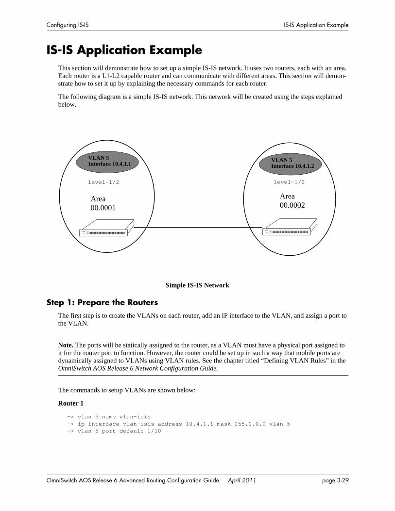
Configuring IS-IS IS-IS Application Example
IS-IS Application ExampleThis section will demonstrate how to set up a simple IS-IS network. It uses two routers, each with an area. Each router is a L1-L2 capable router and can communicate with different areas. This section will demon-strate how to set it up by explaining the necessary commands for each router.
The following diagram is a simple IS-IS network. This network will be created using the steps explained below.
Simple IS-IS Network
Step 1: Prepare the RoutersThe first step is to create the VLANs on each router, add an IP interface to the VLAN, and assign a port to the VLAN.
Note. The ports will be statically assigned to the router, as a VLAN must have a physical port assigned to it for the router port to function. However, the router could be set up in such a way that mobile ports are dynamically assigned to VLANs using VLAN rules. See the chapter titled “Defining VLAN Rules” in the OmniSwitch AOS Release 6 Network Configuration Guide.
The commands to setup VLANs are shown below:
Router 1
-> vlan 5 name vlan-isis-> ip interface vlan-isis address 10.4.1.1 mask 255.0.0.0 vlan 5-> vlan 5 port default 1/10
Area00.0001
Area00.0002
VLAN 5Interface 10.4.1.1
VLAN 5Interface 10.4.1.2
level-1/2 level-1/2
OmniSwitch AOS Release 6 Advanced Routing Configuration Guide April 2011 page 3-29

IS-IS Application Example Configuring IS-IS
Router 2
-> vlan 5 name vlan-isis-> ip interface vlan-isis address 10.4.1.2 mask 255.0.0.0 vlan 5-> vlan 5 port default 1/10
Step 2: Enable IS-ISThe next step is to load and enable IS-IS on each router. The commands for this are shown below (the commands are the same on each router):
-> ip load isis-> ip isis status enable
Step 3: Create and Enable Area IDNow the areas should be created and enabled. The commands for this are shown below:
Router 1
-> ip isis area-id 00.0001
This command created the area for Router 1.
Router 2
-> ip isis area-id 00.0002
This command created the area for Router 2.
Step 4: Configuring IS-IS Level CapabilityThe router must be configured with the IS-IS level capability, which decides whether the router will route traffic within an area or between two or more areas.
Router 1
-> ip isis level-capability level-1/2
Router 2
-> ip isis level-capability level-1/2
Note. The default IS-IS level capability is Level-1/2.
Step 5: Create, Enable, and Assign InterfacesNext, IS-IS interfaces must be enabled. The IS-IS interfaces should have the same IP address as the IP router ports created above in “Step 1: Prepare the Routers” on page 3-29.
Router 1
-> ip isis interface vlan-isis -> ip isis interface vlan-isis status enable
page 3-30 OmniSwitch AOS Release 6 Advanced Routing Configuration Guide April 2011
Configuring IS-IS Verifying IS-IS Configuration
Router 2
-> ip isis interface vlan-isis -> ip isis interface vlan-isis status enable
Step 6: Examine the NetworkAfter the network has been created, you can check various aspects of it using show commands:
• For IS-IS in general, use the show ip isis statistics command.
• For SPF details, use the show ip isis spf command.
• For summarization details, use the show ip isis summary-address command.
• To check for adjacencies formed with neighbors, use the show ip isis adjacency command.
• For routes, use the show ip isis routes command.
• For details of the interfaces, use the show ip isis interface command.
Verifying IS-IS ConfigurationTo verify information about adjacent routers, summary-address, SPF, or IS-IS in general, use the show commands listed in the following table:
For more information about the commands output, see Chapter 3, “Configuring IS-IS” in the OmniSwitch CLI Reference Guide.
show ip isis adjacency Displays information about IS-IS adjacent routers.show ip isis database Displays IS-IS LSP database information of the adjacent routers.show ip isis hostname Displays the database of IS-IS host names.show ip isis routes Displays the IS-IS route information known to the router.show ip isis spf Displays the IS-IS SPF calculation information.show ip isis spf-log Displays the IS-IS SPF log.show ip isis statistics Displays the IS-IS statistics information.show ip isis status Displays the IS-IS status.show ip isis summary-address Displays the IS-IS summary address database.show ip redist Displays the IS-IS configured redistributions.show ip isis interface Displays the IS-IS interface information.
OmniSwitch AOS Release 6 Advanced Routing Configuration Guide April 2011 page 3-31

Verifying IS-IS Configuration Configuring IS-IS
page 3-32 OmniSwitch AOS Release 6 Advanced Routing Configuration Guide April 2011
4 Configuring BGP
The Border Gateway Protocol (BGP) is an exterior routing protocol that guarantees the loop-free exchange of routing information between autonomous systems. The Alcatel-Lucent implementation supports BGP version 4 and the RFCs specified below.
The Alcatel-Lucent implementation of BGP is designed for enterprise networks, specifically for border routers handling a public network connection, such as the organization’s Internet Service Provider (ISP) link.
This chapter describes the configuration and use of BGP in IPv4 and IPv6 environments using the Command Line Interface (CLI). The Alcatel-Lucent implementation of BGP-4 and Multiprotocol Extensions to BGP-4 is based on several RFCs listed below. CLI commands are used in the configuration examples in this chapter. For more details about the syntax of these commands, see the OmniSwitch CLI Reference Guide.
Note. In this document, the BGP terms “peer” and “neighbor” are used interchangeably.
Note. This implementation of BGP allows you to configure and manage BGP in IPv4 and IPv6 environ-ments via CLI, WebView and SNMP interfaces.
In This ChapterThe topics and configuration procedures in this chapter include:
• Setting up global BGP parameters, such as a router’s Autonomous System (AS) number and default local preference. See “Setting Global BGP Parameters” on page 4-20.
• Configuring a BGP peer and setting various parameters on that peer, such as timers, soft reconfigura-tion, and policies. See “Configuring a BGP Peer” on page 4-26.
• Configuring route dampening parameters for the router. See “Controlling Route Flapping Through Route Dampening” on page 4-36.
• Configuring route reflection using single and multiple route reflectors. See “Setting Up Route Reflec-tion” on page 4-40.
• Configuring aggregate routes as well as values for aggregates, such as community strings and local preference. See “Configuring Aggregate Routes” on page 4-32.
• Configuring BGP local networks. See “Configuring Local Routes (Networks)” on page 4-33.
• Configuring confederations. See “Creating a Confederation” on page 4-44.
OmniSwitch AOS Release 6 Advanced Routing Configuration Guide April 2011 page 4-1
In This Chapter Configuring BGP
• Using policies to control BGP routing. See “Routing Policies” on page 4-45.
• Configuring redistribution using route maps. See “Configuring Redistribution” on page 4-53.
• Enabling IPv6 BGP Unicast. See “Enabling/Disabling IPv6 BGP Unicast” on page 4-68.
• Configuring an IPv6 BGP Peer. See “Configuring an IPv6 BGP Peer” on page 4-68.
• Configuring IPv6 BGP Networks. See “Configuring IPv6 BGP Networks” on page 4-72.
• Configuring IPv6 Redistribution. See “Configuring IPv6 Redistribution” on page 4-75.
page 4-2 OmniSwitch AOS Release 6 Advanced Routing Configuration Guide April 2011
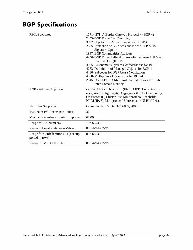
Configuring BGP BGP Specifications
BGP Specifications RFCs Supported 1771/4271–A Border Gateway Protocol 4 (BGP-4)
2439–BGP Route Flap Damping3392–Capabilities Advertisement with BGP-42385–Protection of BGP Sessions via the TCP MD5
Signature Option1997–BGP Communities Attribute4456–BGP Route Reflection: An Alternative to Full Mesh
Internal BGP (IBGP)3065–Autonomous System Confederations for BGP4273–Definitions of Managed Objects for BGP-44486–Subcodes for BGP Cease Notification4760–Multiprotocol Extensions for BGP-42545–Use of BGP-4 Multiprotocol Extensions for IPv6
Inter-Domain Routing
BGP Attributes Supported Origin, AS Path, Next Hop (IPv4), MED, Local Prefer-ence, Atomic Aggregate, Aggregator (IPv4), Community, Originator ID, Cluster List, Multiprotocol Reachable NLRI (IPv6), Multiprotocol Unreachable NLRI (IPv6).
Platforms Supported OmniSwitch 6850, 6850E, 6855, 9000E
Maximum BGP Peers per Router 32
Maximum number of routes supported 65,000
Range for AS Numbers 1 to 65535
Range of Local Preference Values 0 to 4294967295
Range for Confederation IDs (not sup-ported in IPv6)
0 to 65535
Range for MED Attribute 0 to 4294967295
OmniSwitch AOS Release 6 Advanced Routing Configuration Guide April 2011 page 4-3
Quick Steps for Using BGP Configuring BGP
Quick Steps for Using BGP1 The BGP software is not loaded automatically when the router is booted. You must manually load the software into memory by typing the following command:
-> ip load bgp
2 Assign an Autonomous System (AS) number to the local BGP speaker. By default the AS number is 1, but you may want to change this number to fit your network requirements. For example:
-> ip bgp autonomous-system 100
3 Enable the BGP protocol by entering the following command:
-> ip bgp status enable
4 Create a BGP peer entry. The local BGP speaker should be able to reach this peer. The IP address you assign the peer should be valid. For example:
-> ip bgp neighbor 198.45.16.145
5 Assign an AS number to the peer you just created. All peers require an AS number. The AS number does not have to be the same as the AS number for the local BGP speaker. For example:
-> ip bgp neighbor 198.45.16.145 remote-as 200
6 By default a BGP peer is not active on the network until you enable it. Use the following commands to enable the peer created in Step 4:
-> ip bgp neighbor 198.45.16.145 status enable
page 4-4 OmniSwitch AOS Release 6 Advanced Routing Configuration Guide April 2011
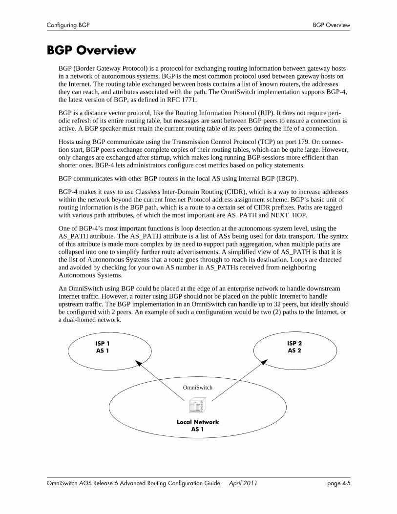
Configuring BGP BGP Overview
BGP OverviewBGP (Border Gateway Protocol) is a protocol for exchanging routing information between gateway hosts in a network of autonomous systems. BGP is the most common protocol used between gateway hosts on the Internet. The routing table exchanged between hosts contains a list of known routers, the addresses they can reach, and attributes associated with the path. The OmniSwitch implementation supports BGP-4, the latest version of BGP, as defined in RFC 1771.
BGP is a distance vector protocol, like the Routing Information Protocol (RIP). It does not require peri-odic refresh of its entire routing table, but messages are sent between BGP peers to ensure a connection is active. A BGP speaker must retain the current routing table of its peers during the life of a connection.
Hosts using BGP communicate using the Transmission Control Protocol (TCP) on port 179. On connec-tion start, BGP peers exchange complete copies of their routing tables, which can be quite large. However, only changes are exchanged after startup, which makes long running BGP sessions more efficient than shorter ones. BGP-4 lets administrators configure cost metrics based on policy statements.
BGP communicates with other BGP routers in the local AS using Internal BGP (IBGP).
BGP-4 makes it easy to use Classless Inter-Domain Routing (CIDR), which is a way to increase addresses within the network beyond the current Internet Protocol address assignment scheme. BGP’s basic unit of routing information is the BGP path, which is a route to a certain set of CIDR prefixes. Paths are tagged with various path attributes, of which the most important are AS_PATH and NEXT_HOP.
One of BGP-4’s most important functions is loop detection at the autonomous system level, using the AS_PATH attribute. The AS_PATH attribute is a list of ASs being used for data transport. The syntax of this attribute is made more complex by its need to support path aggregation, when multiple paths are collapsed into one to simplify further route advertisements. A simplified view of AS_PATH is that it is the list of Autonomous Systems that a route goes through to reach its destination. Loops are detected and avoided by checking for your own AS number in AS_PATHs received from neighboring Autonomous Systems.
An OmniSwitch using BGP could be placed at the edge of an enterprise network to handle downstream Internet traffic. However, a router using BGP should not be placed on the public Internet to handle upstream traffic. The BGP implementation in an OmniSwitch can handle up to 32 peers, but ideally should be configured with 2 peers. An example of such a configuration would be two (2) paths to the Internet, or a dual-homed network.
Local NetworkAS 1
ISP 1AS 1
ISP 2AS 2
OmniSwitch
OmniSwitch AOS Release 6 Advanced Routing Configuration Guide April 2011 page 4-5
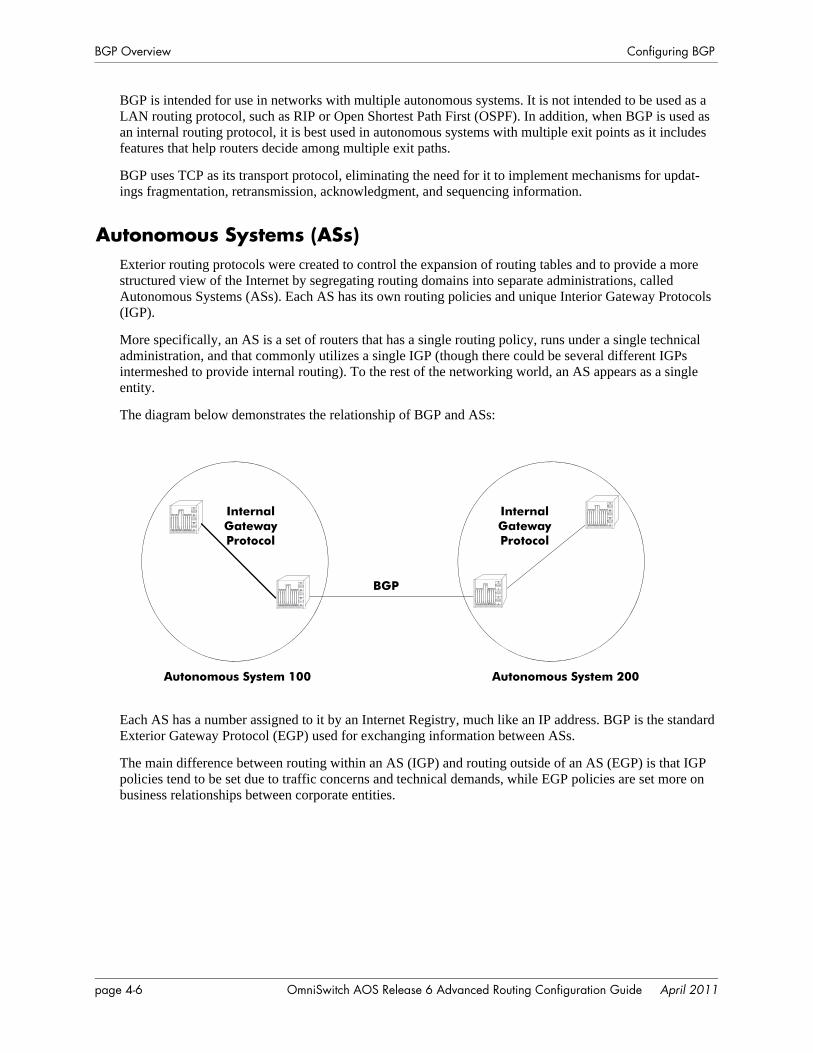
BGP Overview Configuring BGP
BGP is intended for use in networks with multiple autonomous systems. It is not intended to be used as a LAN routing protocol, such as RIP or Open Shortest Path First (OSPF). In addition, when BGP is used as an internal routing protocol, it is best used in autonomous systems with multiple exit points as it includes features that help routers decide among multiple exit paths.
BGP uses TCP as its transport protocol, eliminating the need for it to implement mechanisms for updat-ings fragmentation, retransmission, acknowledgment, and sequencing information.
Autonomous Systems (ASs)Exterior routing protocols were created to control the expansion of routing tables and to provide a more structured view of the Internet by segregating routing domains into separate administrations, called Autonomous Systems (ASs). Each AS has its own routing policies and unique Interior Gateway Protocols (IGP).
More specifically, an AS is a set of routers that has a single routing policy, runs under a single technical administration, and that commonly utilizes a single IGP (though there could be several different IGPs intermeshed to provide internal routing). To the rest of the networking world, an AS appears as a single entity.
The diagram below demonstrates the relationship of BGP and ASs:
Each AS has a number assigned to it by an Internet Registry, much like an IP address. BGP is the standard Exterior Gateway Protocol (EGP) used for exchanging information between ASs.
The main difference between routing within an AS (IGP) and routing outside of an AS (EGP) is that IGP policies tend to be set due to traffic concerns and technical demands, while EGP policies are set more on business relationships between corporate entities.
Autonomous System 100 Autonomous System 200
BGP
Internal Gateway Protocol
Internal Gateway Protocol
page 4-6 OmniSwitch AOS Release 6 Advanced Routing Configuration Guide April 2011
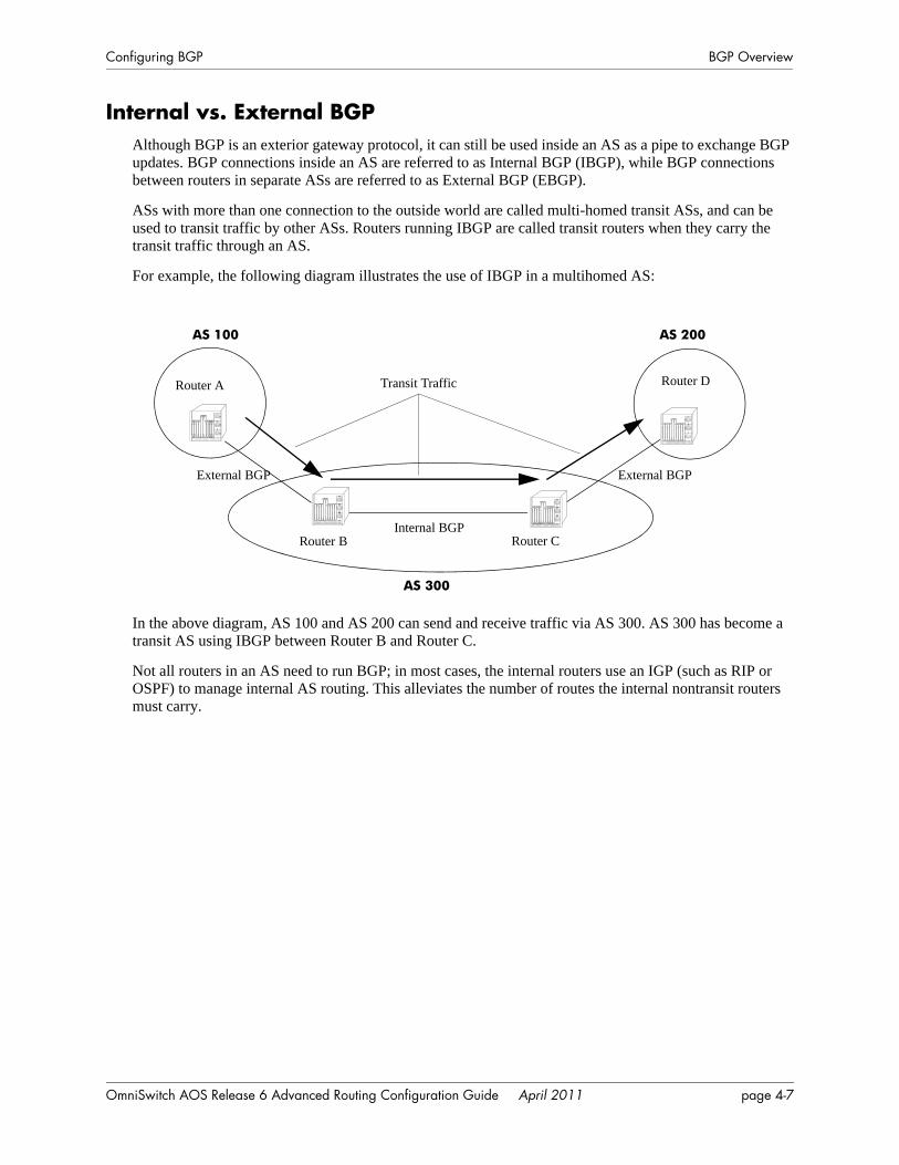
Configuring BGP BGP Overview
Internal vs. External BGPAlthough BGP is an exterior gateway protocol, it can still be used inside an AS as a pipe to exchange BGP updates. BGP connections inside an AS are referred to as Internal BGP (IBGP), while BGP connections between routers in separate ASs are referred to as External BGP (EBGP).
ASs with more than one connection to the outside world are called multi-homed transit ASs, and can be used to transit traffic by other ASs. Routers running IBGP are called transit routers when they carry the transit traffic through an AS.
For example, the following diagram illustrates the use of IBGP in a multihomed AS:
In the above diagram, AS 100 and AS 200 can send and receive traffic via AS 300. AS 300 has become a transit AS using IBGP between Router B and Router C.
Not all routers in an AS need to run BGP; in most cases, the internal routers use an IGP (such as RIP or OSPF) to manage internal AS routing. This alleviates the number of routes the internal nontransit routers must carry.
AS 100 AS 200
AS 300
Internal BGP
External BGPExternal BGP
Transit Traffic
Router CRouter B
Router A Router D
OmniSwitch AOS Release 6 Advanced Routing Configuration Guide April 2011 page 4-7
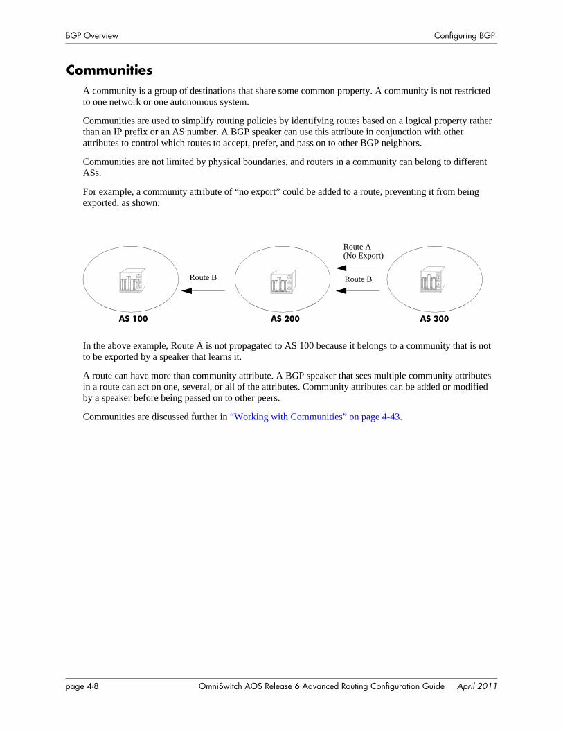
BGP Overview Configuring BGP
CommunitiesA community is a group of destinations that share some common property. A community is not restricted to one network or one autonomous system.
Communities are used to simplify routing policies by identifying routes based on a logical property rather than an IP prefix or an AS number. A BGP speaker can use this attribute in conjunction with other attributes to control which routes to accept, prefer, and pass on to other BGP neighbors.
Communities are not limited by physical boundaries, and routers in a community can belong to different ASs.
For example, a community attribute of “no export” could be added to a route, preventing it from being exported, as shown:
In the above example, Route A is not propagated to AS 100 because it belongs to a community that is not to be exported by a speaker that learns it.
A route can have more than community attribute. A BGP speaker that sees multiple community attributes in a route can act on one, several, or all of the attributes. Community attributes can be added or modified by a speaker before being passed on to other peers.
Communities are discussed further in “Working with Communities” on page 4-43.
Route A (No Export)
Route BRoute B
AS 100 AS 200 AS 300
page 4-8 OmniSwitch AOS Release 6 Advanced Routing Configuration Guide April 2011
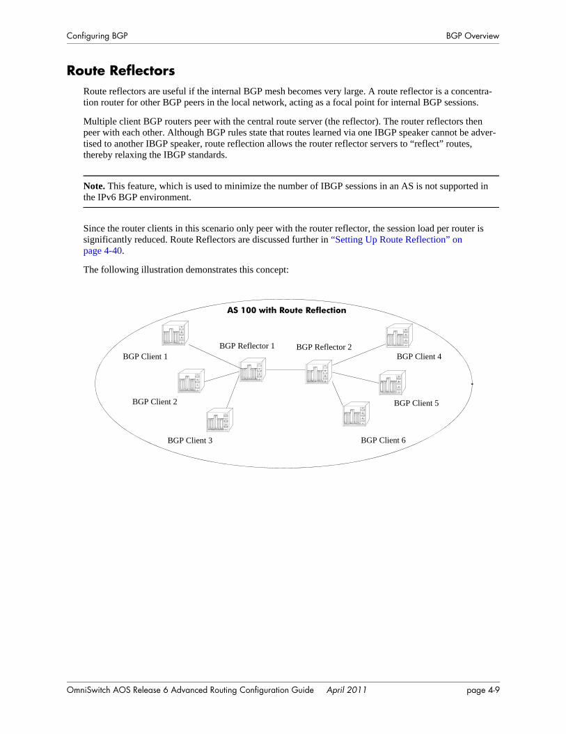
Configuring BGP BGP Overview
Route ReflectorsRoute reflectors are useful if the internal BGP mesh becomes very large. A route reflector is a concentra-tion router for other BGP peers in the local network, acting as a focal point for internal BGP sessions.
Multiple client BGP routers peer with the central route server (the reflector). The router reflectors then peer with each other. Although BGP rules state that routes learned via one IBGP speaker cannot be adver-tised to another IBGP speaker, route reflection allows the router reflector servers to “reflect” routes, thereby relaxing the IBGP standards.
Note. This feature, which is used to minimize the number of IBGP sessions in an AS is not supported in the IPv6 BGP environment.
Since the router clients in this scenario only peer with the router reflector, the session load per router is significantly reduced. Route Reflectors are discussed further in “Setting Up Route Reflection” on page 4-40.
The following illustration demonstrates this concept:
BGP Reflector 2BGP Client 4
BGP Client 3
BGP Client 2
BGP Client 1
BGP Client 5
BGP Client 6
AS 100 with Route Reflection
BGP Reflector 1
OmniSwitch AOS Release 6 Advanced Routing Configuration Guide April 2011 page 4-9
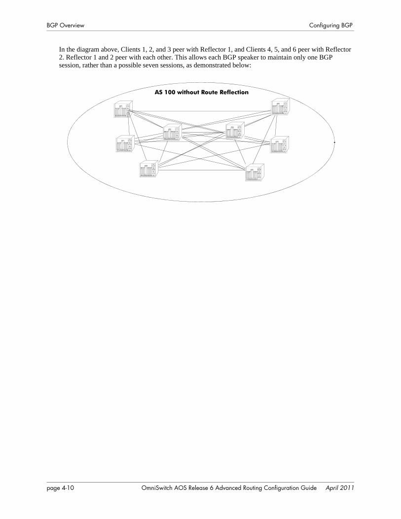
BGP Overview Configuring BGP
In the diagram above, Clients 1, 2, and 3 peer with Reflector 1, and Clients 4, 5, and 6 peer with Reflector 2. Reflector 1 and 2 peer with each other. This allows each BGP speaker to maintain only one BGP session, rather than a possible seven sessions, as demonstrated below:
AS 100 without Route Reflection
page 4-10 OmniSwitch AOS Release 6 Advanced Routing Configuration Guide April 2011
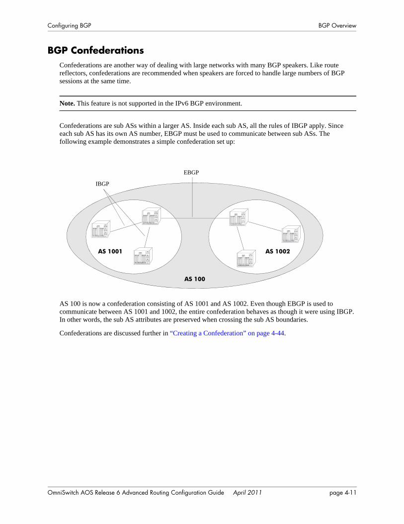
Configuring BGP BGP Overview
BGP ConfederationsConfederations are another way of dealing with large networks with many BGP speakers. Like route reflectors, confederations are recommended when speakers are forced to handle large numbers of BGP sessions at the same time.
Note. This feature is not supported in the IPv6 BGP environment.
Confederations are sub ASs within a larger AS. Inside each sub AS, all the rules of IBGP apply. Since each sub AS has its own AS number, EBGP must be used to communicate between sub ASs. The following example demonstrates a simple confederation set up:
AS 100 is now a confederation consisting of AS 1001 and AS 1002. Even though EBGP is used to communicate between AS 1001 and 1002, the entire confederation behaves as though it were using IBGP. In other words, the sub AS attributes are preserved when crossing the sub AS boundaries.
Confederations are discussed further in “Creating a Confederation” on page 4-44.
AS 100
AS 1001 AS 1002
EBGP
IBGP
OmniSwitch AOS Release 6 Advanced Routing Configuration Guide April 2011 page 4-11
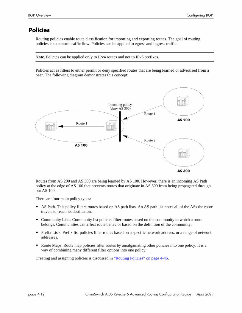
BGP Overview Configuring BGP
PoliciesRouting policies enable route classification for importing and exporting routes. The goal of routing policies is to control traffic flow. Policies can be applied to egress and ingress traffic.
Note. Policies can be applied only to IPv4 routes and not to IPv6 prefixes.
Policies act as filters to either permit or deny specified routes that are being learned or advertised from a peer. The following diagram demonstrates this concept:
Routes from AS 200 and AS 300 are being learned by AS 100. However, there is an incoming AS Path policy at the edge of AS 100 that prevents routes that originate in AS 300 from being propagated through-out AS 100.
There are four main policy types:
• AS Path. This policy filters routes based on AS path lists. An AS path list notes all of the ASs the route travels to reach its destination.
• Community Lists. Community list policies filter routes based on the community to which a route belongs. Communities can affect route behavior based on the definition of the community.
• Prefix Lists. Prefix list policies filter routes based on a specific network address, or a range of network addresses.
• Route Maps. Route map policies filter routes by amalgamating other policies into one policy. It is a way of combining many different filter options into one policy.
Creating and assigning policies is discussed in “Routing Policies” on page 4-45.
AS 100
AS 200
AS 300
Incoming policy (deny AS 300)
Route 1
Route 2
Route 1
page 4-12 OmniSwitch AOS Release 6 Advanced Routing Configuration Guide April 2011
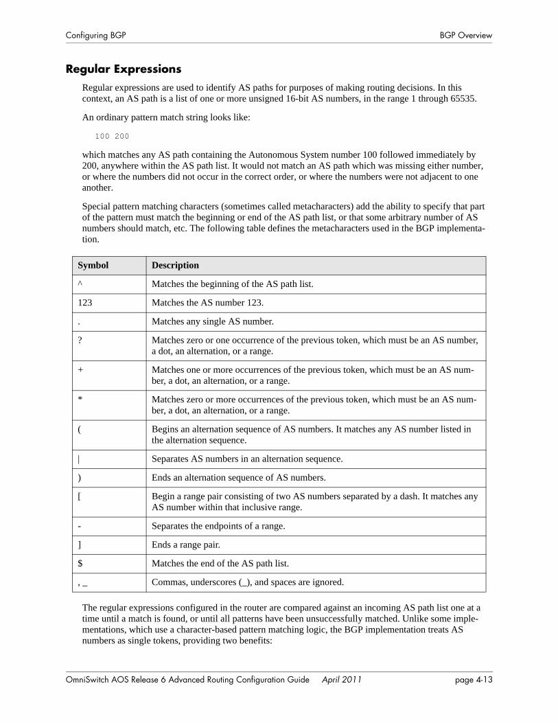
Configuring BGP BGP Overview
Regular ExpressionsRegular expressions are used to identify AS paths for purposes of making routing decisions. In this context, an AS path is a list of one or more unsigned 16-bit AS numbers, in the range 1 through 65535.
An ordinary pattern match string looks like:
100 200
which matches any AS path containing the Autonomous System number 100 followed immediately by 200, anywhere within the AS path list. It would not match an AS path which was missing either number, or where the numbers did not occur in the correct order, or where the numbers were not adjacent to one another.
Special pattern matching characters (sometimes called metacharacters) add the ability to specify that part of the pattern must match the beginning or end of the AS path list, or that some arbitrary number of AS numbers should match, etc. The following table defines the metacharacters used in the BGP implementa-tion.
The regular expressions configured in the router are compared against an incoming AS path list one at a time until a match is found, or until all patterns have been unsuccessfully matched. Unlike some imple-mentations, which use a character-based pattern matching logic, the BGP implementation treats AS numbers as single tokens, providing two benefits:
Symbol Description
^ Matches the beginning of the AS path list.
123 Matches the AS number 123.
. Matches any single AS number.
? Matches zero or one occurrence of the previous token, which must be an AS number, a dot, an alternation, or a range.
+ Matches one or more occurrences of the previous token, which must be an AS num-ber, a dot, an alternation, or a range.
* Matches zero or more occurrences of the previous token, which must be an AS num-ber, a dot, an alternation, or a range.
( Begins an alternation sequence of AS numbers. It matches any AS number listed in the alternation sequence.
| Separates AS numbers in an alternation sequence.
) Ends an alternation sequence of AS numbers.
[ Begin a range pair consisting of two AS numbers separated by a dash. It matches any AS number within that inclusive range.
- Separates the endpoints of a range.
] Ends a range pair.
$ Matches the end of the AS path list.
, _ Commas, underscores (_), and spaces are ignored.
OmniSwitch AOS Release 6 Advanced Routing Configuration Guide April 2011 page 4-13
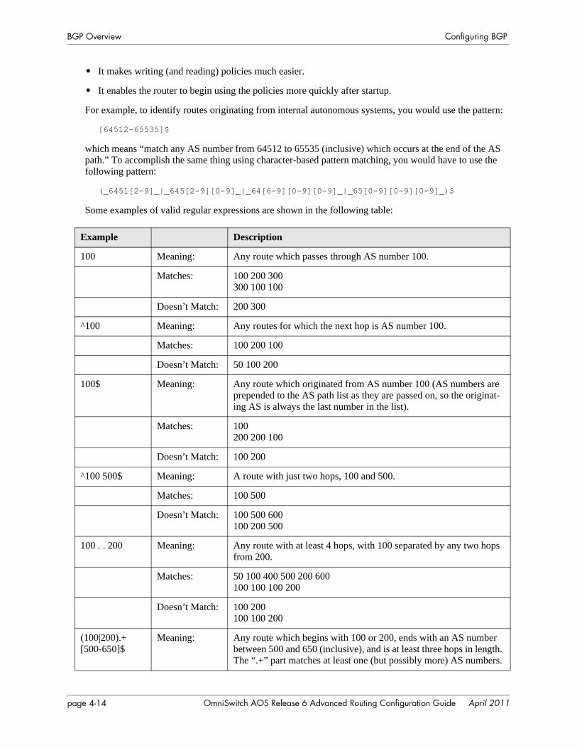
BGP Overview Configuring BGP
• It makes writing (and reading) policies much easier.
• It enables the router to begin using the policies more quickly after startup.
For example, to identify routes originating from internal autonomous systems, you would use the pattern:
[64512-65535]$
which means “match any AS number from 64512 to 65535 (inclusive) which occurs at the end of the AS path.” To accomplish the same thing using character-based pattern matching, you would have to use the following pattern:
(_6451[2-9]_|_645[2-9][0-9]_|_64[6-9][0-9][0-9]_|_65[0-9][0-9][0-9]_)$
Some examples of valid regular expressions are shown in the following table:
Example Description
100 Meaning: Any route which passes through AS number 100.
Matches: 100 200 300300 100 100
Doesn’t Match: 200 300
^100 Meaning: Any routes for which the next hop is AS number 100.
Matches: 100 200 100
Doesn’t Match: 50 100 200
100$ Meaning: Any route which originated from AS number 100 (AS numbers are prepended to the AS path list as they are passed on, so the originat-ing AS is always the last number in the list).
Matches: 100200 200 100
Doesn’t Match: 100 200
^100 500$ Meaning: A route with just two hops, 100 and 500.
Matches: 100 500
Doesn’t Match: 100 500 600100 200 500
100 . . 200 Meaning: Any route with at least 4 hops, with 100 separated by any two hops from 200.
Matches: 50 100 400 500 200 600100 100 100 200
Doesn’t Match: 100 200100 100 200
(100|200).+[500-650]$
Meaning: Any route which begins with 100 or 200, ends with an AS number between 500 and 650 (inclusive), and is at least three hops in length. The “.+” part matches at least one (but possibly more) AS numbers.
page 4-14 OmniSwitch AOS Release 6 Advanced Routing Configuration Guide April 2011
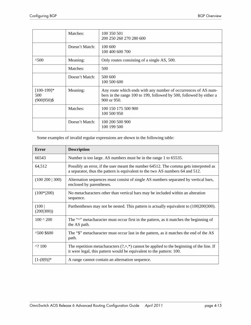
Configuring BGP BGP Overview
Some examples of invalid regular expressions are shown in the following table:
Matches: 100 350 501200 250 260 270 280 600
Doesn’t Match: 100 600100 400 600 700
^500 Meaning: Only routes consisting of a single AS, 500.
Matches: 500
Doesn’t Match: 500 600100 500 600
[100-199]*500(900|950)$
Meaning: Any route which ends with any number of occurrences of AS num-bers in the range 100 to 199, followed by 500, followed by either a 900 or 950.
Matches: 100 150 175 500 900100 500 950
Doesn’t Match: 100 200 500 900100 199 500
Error Description
66543 Number is too large. AS numbers must be in the range 1 to 65535.
64,512 Possibly an error, if the user meant the number 64512. The comma gets interpreted as a separator, thus the pattern is equivalent to the two AS numbers 64 and 512.
(100 200 | 300) Alternation sequences must consist of single AS numbers separated by vertical bars, enclosed by parentheses.
(100*|200) No metacharacters other than vertical bars may be included within an alteration sequence.
(100 | (200|300))
Parthentheses may not be nested. This pattern is actually equivalent to (100|200|300).
100 ^ 200 The “^” metacharacter must occur first in the pattern, as it matches the beginning of the AS path.
^500 $600 The “$” metacharacter must occur last in the pattern, as it matches the end of the AS path.
^? 100 The repetition metacharacters (?,+,*) cannot be applied to the beginning of the line. If it were legal, this pattern would be equivalent to the pattern: 100.
[1-(8|9)]* A range cannot contain an alternation sequence.
OmniSwitch AOS Release 6 Advanced Routing Configuration Guide April 2011 page 4-15
BGP Overview Configuring BGP
The Route Selection ProcessSeveral metrics are used to make BGP routing decisions. These metrics include the route’s local prefer-ence, the AS Path, and the Multi-Exit Discriminator (MED). These metrics are organized into a hierarchy such that if a tie results, the next important criteria is used to break the tie until a decision is made for the route path.
BGP selects the best path to an autonomous system from all known paths and propagates the selected path to its neighbors. BGP uses the following criteria, in order, to select the best path. If routes are equal at a given point in the selection process, then the next criterion is applied to break the tie.
1 The route with the highest local preference.
2 The route with the fewest autonomous systems listed in its AS Path.
3 The AS path origin. A route with an AS path origin of IGP (internal to the AS) is preferred. Next in preference is a route with an AS path origin of EGP (external to the AS). Least preferred is an AS path that is incomplete. In summary, the path origin preference is as follows: IGP < EGP < Incomplete.
4 The route with the lowest Multi-Exit Discriminator (MED). MEDs are by default compared between routes that are received within the same AS. However, you can configure BGP to consider MED values from external peers. This test is only applied if the local AS has two or more connections, or exits, to a neighbor AS.
5 The route with a closer next hop (with respect to the internal routing distance).
6 The source of the route. A strictly interior route is preferred, next in preference is a strictly exterior route, and third in preference is an exterior route learned from an interior session. In summary, the route source preference is as follows: IGP < EBGP < IBGP.
7 Lowest BGP Router ID. The route whose next hop IP address is numerically lowest.
page 4-16 OmniSwitch AOS Release 6 Advanced Routing Configuration Guide April 2011
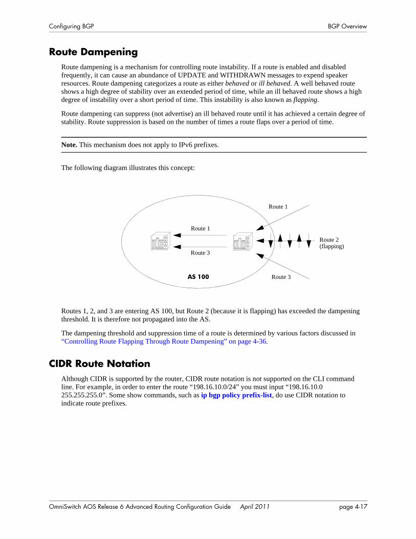
Configuring BGP BGP Overview
Route DampeningRoute dampening is a mechanism for controlling route instability. If a route is enabled and disabled frequently, it can cause an abundance of UPDATE and WITHDRAWN messages to expend speaker resources. Route dampening categorizes a route as either behaved or ill behaved. A well behaved route shows a high degree of stability over an extended period of time, while an ill behaved route shows a high degree of instability over a short period of time. This instability is also known as flapping.
Route dampening can suppress (not advertise) an ill behaved route until it has achieved a certain degree of stability. Route suppression is based on the number of times a route flaps over a period of time.
Note. This mechanism does not apply to IPv6 prefixes.
The following diagram illustrates this concept:
Routes 1, 2, and 3 are entering AS 100, but Route 2 (because it is flapping) has exceeded the dampening threshold. It is therefore not propagated into the AS.
The dampening threshold and suppression time of a route is determined by various factors discussed in “Controlling Route Flapping Through Route Dampening” on page 4-36.
CIDR Route NotationAlthough CIDR is supported by the router, CIDR route notation is not supported on the CLI command line. For example, in order to enter the route “198.16.10.0/24” you must input “198.16.10.0 255.255.255.0”. Some show commands, such as ip bgp policy prefix-list, do use CIDR notation to indicate route prefixes.
Route 1
Route 3
Route 2(flapping)
Route 1
Route 3
AS 100
OmniSwitch AOS Release 6 Advanced Routing Configuration Guide April 2011 page 4-17
BGP Configuration Overview Configuring BGP
BGP Configuration OverviewThe following steps and points summarize configuring BGP. Not all of the following are necessary. For the necessary steps to enable BGP on the OmniSwitch, see “Quick Steps for Using BGP” on page 4-4.
1 Load the BGP protocol. See “Starting BGP” on page 4-19.
2 Set up router-wide parameters, such as the router’s AS number, default local preference, and enable the BGP protocol. See “Setting Global BGP Parameters” on page 4-20.
3 Configure peers on the router. These peers may be in the same AS as the router or in a different AS. See “Configuring a BGP Peer” on page 4-26.
4 Configure peers that operate on remote routers. These peers may be in the same AS as the router or in a different AS. See “Configuring a BGP Peer” on page 4-26.
5 Configure optional parameters. There are many optional features available in the Alcatel-Lucent implementation of BGP-4. These features are described in later sections of this chapter. The following is a list of BGP features you can configure on an OmniSwitch:
• Aggregate Routes. See “Configuring Aggregate Routes” on page 4-32.
• Local networks, or routes. See “Configuring Local Routes (Networks)” on page 4-33.
• Route Dampening. See “Controlling Route Flapping Through Route Dampening” on page 4-36.
• Route Reflection. See “Setting Up Route Reflection” on page 4-40.
• Communities. See “Working with Communities” on page 4-43.
• Confederations. See “Creating a Confederation” on page 4-44.
• Policies to control BGP routing. See “Routing Policies” on page 4-45.
• Redistribution policies using route maps. See “Configuring Redistribution” on page 4-53.
page 4-18 OmniSwitch AOS Release 6 Advanced Routing Configuration Guide April 2011
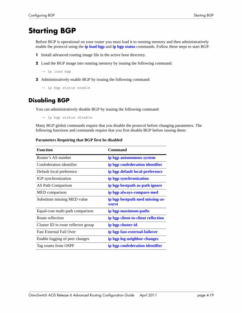
Configuring BGP Starting BGP
Starting BGPBefore BGP is operational on your router you must load it to running memory and then administratively enable the protocol using the ip load bgp and ip bgp status commands. Follow these steps to start BGP.
1 Install advanced routing image file in the active boot directory.
2 Load the BGP image into running memory by issuing the following command:
-> ip load bgp
3 Administratively enable BGP by issuing the following command:
-> ip bgp status enable
Disabling BGPYou can administratively disable BGP by issuing the following command:
-> ip bgp status disable
Many BGP global commands require that you disable the protocol before changing parameters. The following functions and commands require that you first disable BGP before issuing them:
Parameters Requiring that BGP first be disabled
Function Command
Router’s AS number ip bgp autonomous-system
Confederation identifier ip bgp confederation identifier
Default local preference ip bgp default local-preference
IGP synchronization ip bgp synchronization
AS Path Comparison ip bgp bestpath as-path ignore
MED comparison ip bgp always-compare-med
Substitute missing MED value ip bgp bestpath med missing-as-worst
Equal-cost multi-path comparison ip bgp maximum-paths
Route reflection ip bgp client-to-client reflection
Cluster ID in route reflector group ip bgp cluster-id
Fast External Fail Over ip bgp fast-external-failover
Enable logging of peer changes ip bgp log-neighbor-changes
Tag routes from OSPF ip bgp confederation identifier
OmniSwitch AOS Release 6 Advanced Routing Configuration Guide April 2011 page 4-19
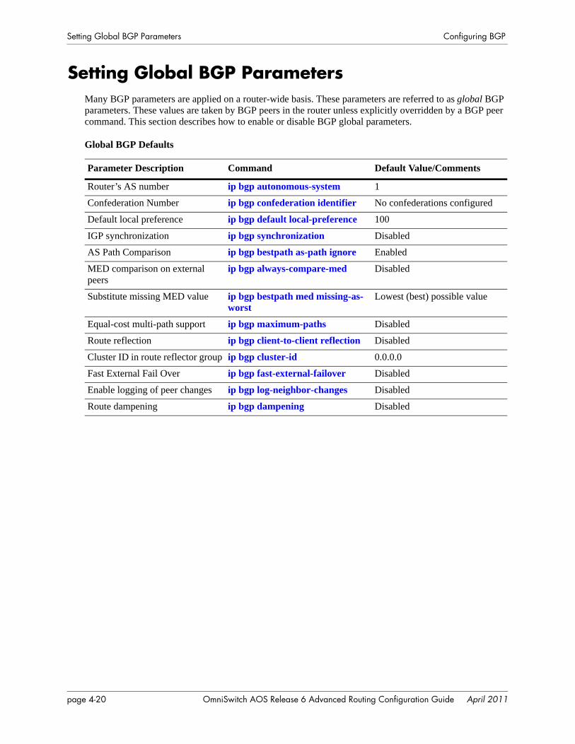
Setting Global BGP Parameters Configuring BGP
Setting Global BGP ParametersMany BGP parameters are applied on a router-wide basis. These parameters are referred to as global BGP parameters. These values are taken by BGP peers in the router unless explicitly overridden by a BGP peer command. This section describes how to enable or disable BGP global parameters.
Global BGP Defaults
Parameter Description Command Default Value/Comments
Router’s AS number ip bgp autonomous-system 1
Confederation Number ip bgp confederation identifier No confederations configured
Default local preference ip bgp default local-preference 100
IGP synchronization ip bgp synchronization Disabled
AS Path Comparison ip bgp bestpath as-path ignore Enabled
MED comparison on external peers
ip bgp always-compare-med Disabled
Substitute missing MED value ip bgp bestpath med missing-as-worst
Lowest (best) possible value
Equal-cost multi-path support ip bgp maximum-paths Disabled
Route reflection ip bgp client-to-client reflection Disabled
Cluster ID in route reflector group ip bgp cluster-id 0.0.0.0
Fast External Fail Over ip bgp fast-external-failover Disabled
Enable logging of peer changes ip bgp log-neighbor-changes Disabled
Route dampening ip bgp dampening Disabled
page 4-20 OmniSwitch AOS Release 6 Advanced Routing Configuration Guide April 2011
Configuring BGP Setting Global BGP Parameters
Setting the Router AS NumberThe router takes a single Autonomous System (AS) number. You can assign one and only one AS number to a router using the ip bgp autonomous-system command. That same router may contain peers that belong to a different AS than the AS you assign your router. In such a case these BGP peers with a differ-ent AS would be considered external BGP (EBGP) peers and the communication with those peers would be EBGP.
The following command would assign an AS number of 14 to a router:
-> ip bgp autonomous-system 14
This command requires that you first disable the BGP protocol. If BGP were already enabled, you would actually need to issue two commands to assign the router’s AS number to 14:
-> ip bgp status disable-> ip bgp autonomous-system 14
Setting the Default Local PreferenceA route’s local preference is an important attribute in the path selection process. In many cases it will be the most important criteria in determining the selection of one route over another. A route obtains its local preference in one of two ways:
• By taking the default local preference established globally in the router.
• By having this default local preference manipulated by another command. The BGP peer, aggregate route, and network commands allow you to assign a local preference to a route. It is also possible to manipulate the local preference of a route through BGP policy commands.
The local preference in the router is set by default to 100. If you want to change this value, use the ip bgp default local-preference command. For example, if you wanted to change the default local prefer-ence for all routes to 200, you would issue the following command:
-> ip bgp default local-preference 200
This command requires that you first disable the BGP protocol. If BGP were already enabled, you would actually need to issue two commands to change the default local preference to 200:
-> ip bgp status disable-> ip bgp default local-preference 200
OmniSwitch AOS Release 6 Advanced Routing Configuration Guide April 2011 page 4-21
Setting Global BGP Parameters Configuring BGP
Enabling AS Path ComparisonThe AS path is a route attribute that shows the sequence of ASs through which a route has traveled. For example if a path originated in AS 1, then went through AS 3, and reached its destination in AS 4, then the AS path would be:
4 3 1
A shorter AS path is preferred over a longer AS path. The AS path is always advertised in BGP route updates, however you can control whether BGP uses this attribute when comparing routes. The length of the AS path may not always indicate the effectiveness for a given route. For example, if a route has an AS path of:
1 3 4
using only T1 links, it might not be a faster path than a longer AS path of:
2 4 5 7
that uses only DS-3 links.
By default AS path comparison is enabled. You can disable it by specifying:
-> no ip bgp bestpath as-path ignore
This command requires that you first disable the BGP protocol. If BGP were already enabled, you would actually need to issue two commands to turn off AS path comparison:
-> ip bgp status disable
-> no ip bgp bestpath as-path ignore
page 4-22 OmniSwitch AOS Release 6 Advanced Routing Configuration Guide April 2011
Configuring BGP Setting Global BGP Parameters
Controlling the use of MED ValuesThe Multi Exit Discriminator, or MED, is used by border routers (i.e., BGP speakers with links to neigh-boring autonomous systems) to help choose between multiple entry and exit points for an autonomous system. It is only relevant when an AS has more than one connection to a neighboring AS. If all other factors are equal, the path with the lowest MED value takes preference over other paths to the neighbor AS.
If received on external links, the MED may be propagated over internal links to other BGP speakers in the same AS. However, the MED is never propagated to speakers in a neighboring AS. The MED attribute indicates the weight of a particular exit point from an AS. Some exit points may be given a better MED value because they lead to higher speed connections.
The Alcatel-Lucent implementation of BGP allows you to control MED values in the following ways:
• Compare MED values for external ASs
• Insert a MED value in routes that do not contain MEDs
The following two sections describe these MED control features.
Enabling MED Comparison for External Peers
By default, BGP only compares MEDs from peers within the same autonomous system when selecting routes. However, you can configure BGP to compare MEDs values received from external peers, or other autonomous systems. To enable MED comparison of external peers specify:
-> ip bgp always-compare-med
This command requires that you first disable the BGP protocol. If BGP were already enabled, you would actually need to issue two commands to disable MED comparison:
-> ip bgp status disable
-> no ip bgp always-compare-med
Inserting Missing MED Values
A MED value may be missing in a route received from an external peer. Your can specify how a missing MED in an external BGP path is to be treated for route selection purposes. The default behavior is to treat missing MEDs as zero (best). The ip bgp bestpath med missing-as-worst command allows you to treat missing MEDs as 232-1 (worst) for compatibility reasons.
To change the missing MED value from worst to best, enter the following command:
-> ip bgp bestpath med missing-as-worst
OmniSwitch AOS Release 6 Advanced Routing Configuration Guide April 2011 page 4-23
Setting Global BGP Parameters Configuring BGP
Synchronizing BGP and IGP RoutesThe default behavior of BGP requires that it must be synchronized with the IGP before BGP may adver-tise transit routes to external ASs. It is important that your network is consistent about the routes it adver-tises, otherwise traffic can be lost.
The BGP rule is that a BGP router should not advertise to external neighbors destinations learned from IBGP neighbors unless those destinations are also known via an IGP. This is known as synchronization. If a router knows about a destination via an IGP, it is assumed that the route has already been propagated inside the AS and internal reachability is ensured.
The consequence of injecting BGP routes inside an IGP is costly. Redistributing routes from BGP into the IGP results in major overhead on the internal routers, and IGPs are really not designed to handle that many routes.
The ip bgp synchronization command enables or disables BGP internal synchronization. Enabling this command will force all routers (BGP and non-BGP) in an AS to learn all routes learned over external BGP. Learning the external routes forces the routing tables for all routers in an AS to be synchronized and ensure that all routes advertised within an AS are known to all routers (BGP and non-BGP). However, since routes learned over external BGP can be numerous, enabling synchronization can place an extra burden on non-BGP routers.
To enable synchronization, enter the following command:
-> ip bgp synchronization
The BGP speaker will now synchronize with the IGP. The default for synchronization is disabled.
To deactivate synchronization, enter the same command with the no keyword, as shown:
-> no ip bgp synchronization
page 4-24 OmniSwitch AOS Release 6 Advanced Routing Configuration Guide April 2011
Configuring BGP Setting Global BGP Parameters
Displaying Global BGP ParametersThe following list shows the commands for viewing the various aspects of BGP set with the global BGP commands:
For more information about the output from these show commands, see the OmniSwitch CLI Reference Guide.
show ip bgp Displays the current global settings for the local BGP speaker.show ip bgp statistics Displays BGP global statistics, such as the route paths.show ip bgp aggregate-address Displays aggregate configuration information.show ip bgp dampening Displays the current route dampening configuration settings.show ip bgp dampening-stats Displays route flapping statistics.show ip bgp network Displays information on the currently defined BGP networks.show ip bgp path Displays information, such as Next Hop and other BGP attributes, for
every path in the BGP routing table.show ip bgp routes Displays information on BGP routes known to the router. This informa-
tion includes whether changes to the route are in progress, whether it is part of an aggregate route, and whether it is dampened.
OmniSwitch AOS Release 6 Advanced Routing Configuration Guide April 2011 page 4-25
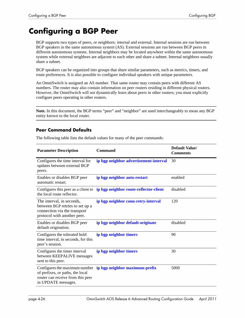
Configuring a BGP Peer Configuring BGP
Configuring a BGP PeerBGP supports two types of peers, or neighbors: internal and external. Internal sessions are run between BGP speakers in the same autonomous system (AS). External sessions are run between BGP peers in different autonomous systems. Internal neighbors may be located anywhere within the same autonomous system while external neighbors are adjacent to each other and share a subnet. Internal neighbors usually share a subnet.
BGP speakers can be organized into groups that share similar parameters, such as metrics, timers, and route preferences. It is also possible to configure individual speakers with unique parameters.
An OmniSwitch is assigned an AS number. That same router may contain peers with different AS numbers. The router may also contain information on peer routers residing in different physical routers. However, the OmniSwitch will not dynamically learn about peers in other routers; you must explicitly configure peers operating in other routers.
Note. In this document, the BGP terms “peer” and “neighbor” are used interchangeably to mean any BGP entity known to the local router.
Peer Command Defaults
The following table lists the default values for many of the peer commands:
Parameter Description Command Default Value/Comments
Configures the time interval for updates between external BGP peers.
ip bgp neighbor advertisement-interval 30
Enables or disables BGP peer automatic restart.
ip bgp neighbor auto-restart enabled
Configures this peer as a client to the local route reflector.
ip bgp neighbor route-reflector-client disabled
The interval, in seconds, between BGP retries to set up a connection via the transport protocol with another peer.
ip bgp neighbor conn-retry-interval 120
Enables or disables BGP peer default origination.
ip bgp neighbor default-originate disabled
Configures the tolerated hold time interval, in seconds, for this peer’s session.
ip bgp neighbor timers 90
Configures the timer interval between KEEPALIVE messages sent to this peer.
ip bgp neighbor timers 30
Configures the maximum number of prefixes, or paths, the local router can receive from this peer in UPDATE messages.
ip bgp neighbor maximum-prefix 5000
page 4-26 OmniSwitch AOS Release 6 Advanced Routing Configuration Guide April 2011
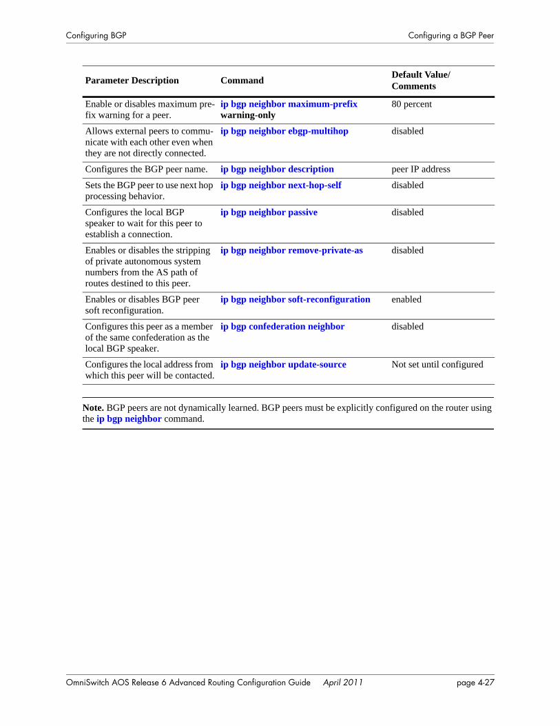
Configuring BGP Configuring a BGP Peer
Note. BGP peers are not dynamically learned. BGP peers must be explicitly configured on the router using the ip bgp neighbor command.
Enable or disables maximum pre-fix warning for a peer.
ip bgp neighbor maximum-prefixwarning-only
80 percent
Allows external peers to commu-nicate with each other even when they are not directly connected.
ip bgp neighbor ebgp-multihop disabled
Configures the BGP peer name. ip bgp neighbor description peer IP address
Sets the BGP peer to use next hop processing behavior.
ip bgp neighbor next-hop-self disabled
Configures the local BGP speaker to wait for this peer to establish a connection.
ip bgp neighbor passive disabled
Enables or disables the stripping of private autonomous system numbers from the AS path of routes destined to this peer.
ip bgp neighbor remove-private-as disabled
Enables or disables BGP peer soft reconfiguration.
ip bgp neighbor soft-reconfiguration enabled
Configures this peer as a member of the same confederation as the local BGP speaker.
ip bgp confederation neighbor disabled
Configures the local address from which this peer will be contacted.
ip bgp neighbor update-source Not set until configured
Parameter Description Command Default Value/Comments
OmniSwitch AOS Release 6 Advanced Routing Configuration Guide April 2011 page 4-27
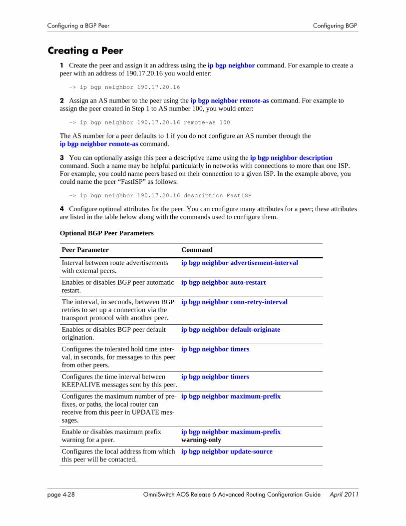
Configuring a BGP Peer Configuring BGP
Creating a Peer1 Create the peer and assign it an address using the ip bgp neighbor command. For example to create a peer with an address of 190.17.20.16 you would enter:
-> ip bgp neighbor 190.17.20.16
2 Assign an AS number to the peer using the ip bgp neighbor remote-as command. For example to assign the peer created in Step 1 to AS number 100, you would enter:
-> ip bgp neighbor 190.17.20.16 remote-as 100
The AS number for a peer defaults to 1 if you do not configure an AS number through theip bgp neighbor remote-as command.
3 You can optionally assign this peer a descriptive name using the ip bgp neighbor description command. Such a name may be helpful particularly in networks with connections to more than one ISP. For example, you could name peers based on their connection to a given ISP. In the example above, you could name the peer “FastISP” as follows:
-> ip bgp neighbor 190.17.20.16 description FastISP
4 Configure optional attributes for the peer. You can configure many attributes for a peer; these attributes are listed in the table below along with the commands used to configure them.
Optional BGP Peer Parameters
Peer Parameter Command
Interval between route advertisements with external peers.
ip bgp neighbor advertisement-interval
Enables or disables BGP peer automatic restart.
ip bgp neighbor auto-restart
The interval, in seconds, between BGP retries to set up a connection via the transport protocol with another peer.
ip bgp neighbor conn-retry-interval
Enables or disables BGP peer default origination.
ip bgp neighbor default-originate
Configures the tolerated hold time inter-val, in seconds, for messages to this peer from other peers.
ip bgp neighbor timers
Configures the time interval between KEEPALIVE messages sent by this peer.
ip bgp neighbor timers
Configures the maximum number of pre-fixes, or paths, the local router can receive from this peer in UPDATE mes-sages.
ip bgp neighbor maximum-prefix
Enable or disables maximum prefix warning for a peer.
ip bgp neighbor maximum-prefixwarning-only
Configures the local address from which this peer will be contacted.
ip bgp neighbor update-source
page 4-28 OmniSwitch AOS Release 6 Advanced Routing Configuration Guide April 2011

Configuring BGP Configuring a BGP Peer
5 After entering all commands to configure a peer you need to administratively enable the peer. The peer will not begin advertising routes until you enable it. To enable the peer in the above step, enter the ip bgp neighbor status command:
-> ip bgp neighbor 190.17.20.16 status enable
Restarting a PeerMany BGP peer commands will automatically restart the peer once they are executed. By restarting the peer, these parameters take effect as soon as the peer comes back up. However, there are some peer commands (such as those configuring timer values) that do not reset the peer. If you want these parame-ters to take effect, then you must manually restart the BGP peer using the ip bgp neighbor clear. The following command would restart the peer at address 190.17.20.16:
-> ip bgp neighbor 190.17.20.16 clear
The peer is not available to send or receive update or notification messages while it is restarting.
Use the ip bgp neighbor clear soft command to reset peer policy parameters.
Setting the Peer Auto RestartWhen the auto restart is enabled, this peer will automatically attempt to restart a session with another peer after a session with that peer terminates.
To enable the auto restart feature, enter the ip bgp neighbor auto-restart command with the peer IP address, as shown:
-> ip bgp neighbor 190.17.20.16 auto-restart
To disable this feature, enter the following:
-> no ip bgp neighbor 190.17.20.16 auto-restart
Allows external peers to communicate with each other even when they are not directly connected.
ip bgp neighbor ebgp-multihop
Sets the BGP peer to use next hop pro-cessing behavior.
ip bgp neighbor next-hop-self
Configures the local BGP speaker to wait for this peer to establish a connection.
ip bgp neighbor passive
Enables or disables the stripping of pri-vate autonomous system numbers from the AS path of routes destined to this peer.
ip bgp neighbor remove-private-as
Enables or disables BGP peer soft recon-figuration.
ip bgp neighbor soft-reconfiguration
Peer Parameter Command
OmniSwitch AOS Release 6 Advanced Routing Configuration Guide April 2011 page 4-29
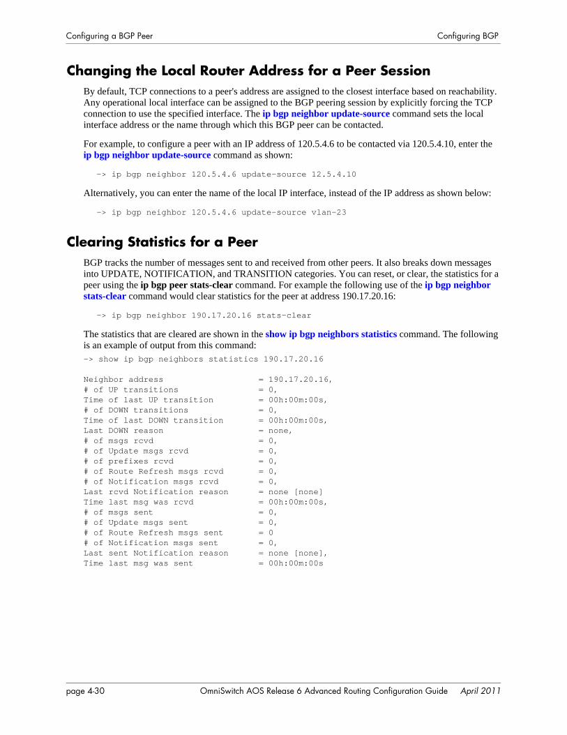
Configuring a BGP Peer Configuring BGP
Changing the Local Router Address for a Peer SessionBy default, TCP connections to a peer's address are assigned to the closest interface based on reachability. Any operational local interface can be assigned to the BGP peering session by explicitly forcing the TCP connection to use the specified interface. The ip bgp neighbor update-source command sets the local interface address or the name through which this BGP peer can be contacted.
For example, to configure a peer with an IP address of 120.5.4.6 to be contacted via 120.5.4.10, enter the ip bgp neighbor update-source command as shown:
-> ip bgp neighbor 120.5.4.6 update-source 12.5.4.10
Alternatively, you can enter the name of the local IP interface, instead of the IP address as shown below:
-> ip bgp neighbor 120.5.4.6 update-source vlan-23
Clearing Statistics for a PeerBGP tracks the number of messages sent to and received from other peers. It also breaks down messages into UPDATE, NOTIFICATION, and TRANSITION categories. You can reset, or clear, the statistics for a peer using the ip bgp peer stats-clear command. For example the following use of the ip bgp neighbor stats-clear command would clear statistics for the peer at address 190.17.20.16:
-> ip bgp neighbor 190.17.20.16 stats-clear
The statistics that are cleared are shown in the show ip bgp neighbors statistics command. The following is an example of output from this command:-> show ip bgp neighbors statistics 190.17.20.16
Neighbor address = 190.17.20.16,# of UP transitions = 0,Time of last UP transition = 00h:00m:00s,# of DOWN transitions = 0,Time of last DOWN transition = 00h:00m:00s,Last DOWN reason = none,# of msgs rcvd = 0,# of Update msgs rcvd = 0,# of prefixes rcvd = 0,# of Route Refresh msgs rcvd = 0,# of Notification msgs rcvd = 0,Last rcvd Notification reason = none [none]Time last msg was rcvd = 00h:00m:00s,# of msgs sent = 0,# of Update msgs sent = 0,# of Route Refresh msgs sent = 0# of Notification msgs sent = 0,Last sent Notification reason = none [none],Time last msg was sent = 00h:00m:00s
page 4-30 OmniSwitch AOS Release 6 Advanced Routing Configuration Guide April 2011
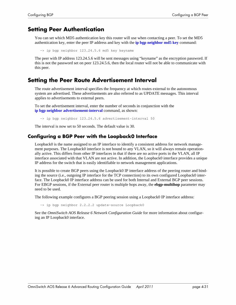
Configuring BGP Configuring a BGP Peer
Setting Peer AuthenticationYou can set which MD5 authentication key this router will use when contacting a peer. To set the MD5 authentication key, enter the peer IP address and key with the ip bgp neighbor md5 key command:
-> ip bgp neighbor 123.24.5.6 md5 key keyname
The peer with IP address 123.24.5.6 will be sent messages using “keyname” as the encryption password. If this is not the password set on peer 123.24.5.6, then the local router will not be able to communicate with this peer.
Setting the Peer Route Advertisement IntervalThe route advertisement interval specifies the frequency at which routes external to the autonomous system are advertised. These advertisements are also referred to as UPDATE messages. This interval applies to advertisements to external peers.
To set the advertisement interval, enter the number of seconds in conjunction with the ip bgp neighbor advertisement-interval command, as shown:
-> ip bgp neighbor 123.24.5.6 advertisement-interval 50
The interval is now set to 50 seconds. The default value is 30.
Configuring a BGP Peer with the Loopback0 InterfaceLoopback0 is the name assigned to an IP interface to identify a consistent address for network manage-ment purposes. The Loopback0 interface is not bound to any VLAN, so it will always remain operation-ally active. This differs from other IP interfaces in that if there are no active ports in the VLAN, all IP interface associated with that VLAN are not active. In addition, the Loopback0 interface provides a unique IP address for the switch that is easily identifiable to network management applications.
It is possible to create BGP peers using the Loopback0 IP interface address of the peering router and bind-ing the source (i.e., outgoing IP interface for the TCP connection) to its own configured Loopback0 inter-face. The Loopback0 IP interface address can be used for both Internal and External BGP peer sessions. For EBGP sessions, if the External peer router is multiple hops away, the ebgp-multihop parameter may need to be used.
The following example configures a BGP peering session using a Loopback0 IP interface address:
-> ip bgp neighbor 2.2.2.2 update-source Loopback0
See the OmniSwitch AOS Release 6 Network Configuration Guide for more information about configur-ing an IP Loopback0 interface.
OmniSwitch AOS Release 6 Advanced Routing Configuration Guide April 2011 page 4-31
Configuring Aggregate Routes Configuring BGP
Configuring Aggregate RoutesAggregate routes are used to reduce the size of routing tables by combining the attributes of several differ-ent routes and allowing a single aggregate route to be advertised to peers.
You cannot aggregate an address (for example, 100.10.0.0) if you do not have at least one more-specific route of the address (for example, 100.10.20.0) in the BGP routing table.
Aggregate routes do not need to be known to the local BGP speaker.
1 Indicate the address and mask for the aggregate route using the ip bgp aggregate-address command:
-> ip bgp aggregate-address 172.22.2.0 255.255.255.0
2 Supress the individual routes in the 172.22.2.0 network and advertise only one route using theip bgp aggregate-address command with the summary-only parameter:
-> ip bgp aggregate-address 172.22.2.0 255.255.255.0 summary-only
3 Optional. When an aggregate route is created BGP does not aggregate the AS paths of all routes included in the aggregate. However, you may specify that a new AS path be created for the aggregate route that includes the ASs traversed for all routes in the aggregate. To specify that the AS path also be aggregated use the ip bgp aggregate-address as-set command. For example:
-> ip bgp aggregate-address 172.22.2.0 255.255.255.0 as-set
4 Optional. By default an aggregate route suppresses the advertisement of all more-specific routes within the aggregate. This suppression of routes is the function of an aggregate route. However, you can disable route summarization through the no ip bgp aggregate-address summary-only. For example:
-> no ip bgp aggregate-address 172.22.2.0 255.255.255.0 summary-only
5 Optional. You can manipulate several BGP attributes for routes included in this aggregate route. These attributes and the corresponding commands used to manipulate them are shown in the table below:
Optional Aggregate Route Attribute Manipulation
6 Once you have finished configuring values for this aggregate route, enable it using the ip bgp aggregate-address status command. For example:
-> ip bgp aggregate-address 172.22.2.0 255.255.255.0 status enable
BGP Attribute Command
Community list for this aggregate route ip bgp aggregate-address community
Local preference value for this aggregate. This value overrides the value set in the ip bgp default-lpref command.
ip bgp aggregate-address local-preference
MED value for this aggregate route. ip bgp aggregate-address metric
page 4-32 OmniSwitch AOS Release 6 Advanced Routing Configuration Guide April 2011
Configuring BGP Configuring Local Routes (Networks)
Configuring Local Routes (Networks)A local BGP network is used to indicate to BGP that a network should originate from a specified router. A network must be known to the local BGP speaker; it also must originate from the local BGP speaker.
Networks have some parameters that can be configured, such as local-preference, community, and metric.
Adding the NetworkTo add a local network to a BGP speaker, use the IP address and mask of the local network in conjunction with the ip bgp network command, as shown:
-> ip bgp network 172.20.2.0 255.255.255.0
In this example, network 172.20.2.0 with a mask of 255.255.255.0 is the local network for this BGP speaker.
To remove the same network from the speaker, enter the same command with the no keyword, as shown:
-> no ip bgp network 172.20.2.0 255.255.255.0
The network would now no longer be associated as the local network for this BGP speaker.
Enabling the Network
Once the network has been added to the speaker, it must be enabled on the speaker. To do this, enter the IP address and mask of the local network in conjunction with the ip bgp network status command, as shown:
-> ip bgp network 172.20.2.0 255.255.255.0 status enable
In this example, network 172.20.2.0 with a mask of 255.255.255.0 has now been enabled.
To disable the same network, enter the following:
-> ip bgp network 172.20.2.0 255.255.255.0 status disable
The network would now be disabled, though not removed from the speaker.
OmniSwitch AOS Release 6 Advanced Routing Configuration Guide April 2011 page 4-33
Configuring Local Routes (Networks) Configuring BGP
Configuring Network ParametersOnce a local network is added to a speaker, you can configure three parameters that are attached to routes generated by the ip bgp network command. These three attributes are the local preference, the commu-nity, and the route metric.
Local Preference
The local preference is a degree of preference to be given to a specific route when there are multiple routes to the same destination. The higher the number, the higher the preference. For example, a route with a local preference of 50 will be used before a route with a local preference of 30.
To set the local preference for the local network, enter the IP address and mask of the local network in conjunction with the ip bgp network local-preference command and value, as shown:
-> ip bgp network 172.20.2.0 255.255.255.0 local-preference 600
The local preference for routes generated by the network is now 600. The default value is 0 (no network local preference is set).
Community
Communities are a way of grouping BGP destination addresses that share some common property. Adding the local network to a specific community indicates that the network shares a common set of properties with the rest of the community.
To add a network to a community, enter the local network IP address and mask in conjunction with the ip bgp network community command and name, as shown:
-> ip bgp network 172.20.2.0 255.255.255.0 community 100:200
Network 172.20.2.0, mask 255.255.255.0, is now in the 100:200 community. The default community is no community.
To remove the local network from the community, enter the local network as above with the community set to “none”, as shown:
-> ip bgp network 172.20.2.0 255.255.255.0 community none
The network is now no longer in any community.
Metric
A metric for a network is the Multi-Exit Discriminator (MED) value. This value is used when announcing this network to internal peers; it indicates the best exit point from the AS, assuming there is more than one. A lower value indicates a more preferred exit point. For example, a route with a MED of 10 is more likely to be used than a route with an MED of 100.
To set the network metric value, enter the network IP address and mask in conjunction with the ip bgp network metric command and value, as shown:
-> ip bgp network 172.20.2.0 255.255.255.0 metric 100
Network 172.20.2.0, mask 255.255.255.0, is now set with a metric of 100. The default metric is 0.
page 4-34 OmniSwitch AOS Release 6 Advanced Routing Configuration Guide April 2011
Configuring BGP Configuring Local Routes (Networks)
Viewing Network SettingsTo view the network settings for all networks assigned to the speaker, enter the show ip bgp network command, as shown:
-> show ip bgp network
A display similar to the following appears:
Network Mask Admin state Oper state---------------+---------------+-----------+----------155.132.40.0 255.255.255.0 disabled not_active 155.132.1.3 255.255.255.255 disabled not_active
To display a specific network, enter the same command with the network IP address and mask, as shown:
-> show ip bgp network 172.20.2.0 255.255.255.0
A display similar to the following appears:
Network address = 172.20.2.0,Network mask = 255.255.255.0,Network admin state = disabled,Network oper state = not_active,Network metric = 0,Network local pref = 0,Network community string = 0:500 400:1 300:2
OmniSwitch AOS Release 6 Advanced Routing Configuration Guide April 2011 page 4-35
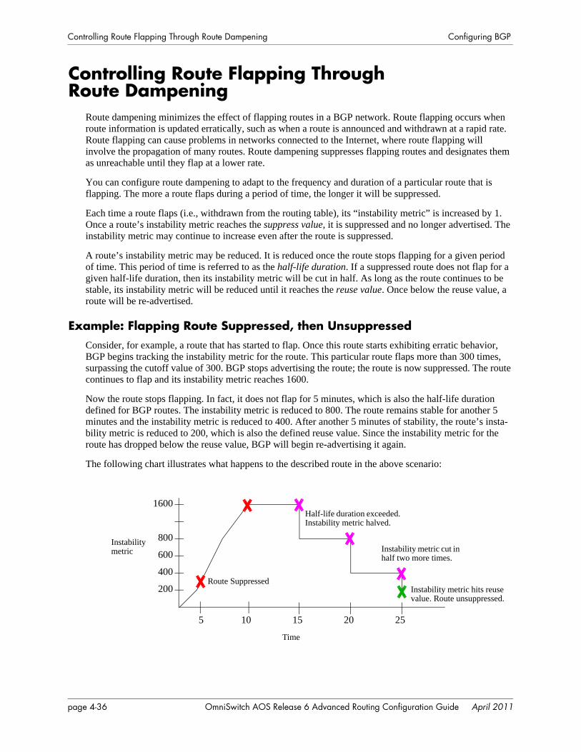
Controlling Route Flapping Through Route Dampening Configuring BGP
Controlling Route Flapping Through Route Dampening
Route dampening minimizes the effect of flapping routes in a BGP network. Route flapping occurs when route information is updated erratically, such as when a route is announced and withdrawn at a rapid rate. Route flapping can cause problems in networks connected to the Internet, where route flapping will involve the propagation of many routes. Route dampening suppresses flapping routes and designates them as unreachable until they flap at a lower rate.
You can configure route dampening to adapt to the frequency and duration of a particular route that is flapping. The more a route flaps during a period of time, the longer it will be suppressed.
Each time a route flaps (i.e., withdrawn from the routing table), its “instability metric” is increased by 1. Once a route’s instability metric reaches the suppress value, it is suppressed and no longer advertised. The instability metric may continue to increase even after the route is suppressed.
A route’s instability metric may be reduced. It is reduced once the route stops flapping for a given period of time. This period of time is referred to as the half-life duration. If a suppressed route does not flap for a given half-life duration, then its instability metric will be cut in half. As long as the route continues to be stable, its instability metric will be reduced until it reaches the reuse value. Once below the reuse value, a route will be re-advertised.
Example: Flapping Route Suppressed, then UnsuppressedConsider, for example, a route that has started to flap. Once this route starts exhibiting erratic behavior, BGP begins tracking the instability metric for the route. This particular route flaps more than 300 times, surpassing the cutoff value of 300. BGP stops advertising the route; the route is now suppressed. The route continues to flap and its instability metric reaches 1600.
Now the route stops flapping. In fact, it does not flap for 5 minutes, which is also the half-life duration defined for BGP routes. The instability metric is reduced to 800. The route remains stable for another 5 minutes and the instability metric is reduced to 400. After another 5 minutes of stability, the route’s insta-bility metric is reduced to 200, which is also the defined reuse value. Since the instability metric for the route has dropped below the reuse value, BGP will begin re-advertising it again.
The following chart illustrates what happens to the described route in the above scenario:
Instability metric
200
400
600
800
1600
Time
Route Suppressed
Half-life duration exceeded. Instability metric halved.
Instability metric cut in half two more times.
Instability metric hits reuse value. Route unsuppressed.
5 10 15 20 25
page 4-36 OmniSwitch AOS Release 6 Advanced Routing Configuration Guide April 2011
Configuring BGP Controlling Route Flapping Through Route Dampening
Enabling Route DampeningRoute dampening is disabled by default. Route dampening must be enabled before it effects routes. To enable route dampening on a BGP router, enter the ip bgp dampening command, as shown:
-> ip bgp dampening
To disable route dampening, enter the following:
-> no ip bgp dampening
Configuring Dampening ParametersThere are several factors in configuring route dampening. These factors work together to determine if a route should be dampened, and for how long. The values all have defaults that are in place when dampen-ing is enabled. It is possible to change these values, using the ip bgp dampening command with vari-ables. The variables for these parameters must be entered together, in one command, in order. This is demonstrated in the following sections.
• Setting the Reach Halflife. The reach halflife is the number of seconds a route can be reached, without flapping, before the penalty number (of flaps) is reduced by half. See “Setting the Reach Halflife” on page 4-37 for instructions on how this is done.
• Setting the Reuse Value. The reuse value determines if a route is advertised again. See “Setting the Reuse Value” on page 4-38 for instructions on how this is done.
• Setting the Suppress Value. The suppress value is the number of route withdrawals required before the route is suppressed. See “Setting the Suppress Value” on page 4-38 for instructions on how this is done.
• Setting the Maximum Suppress Holdtime. The maximum holdtime is the number of seconds a route stays suppressed. See “Setting the Maximum Suppress Holdtime” on page 4-38 for instructions on how this is done.
Setting the Reach Halflife
The reach halflife value is the number of seconds that pass before a route is re-evaluated in terms of flap-ping. After the number of seconds set for halflife has passed, and a route has not flapped, then its total flap count is reduced by half.
For example, if the reach halflife is set at 500 seconds, and a reachable route with a flap count of 300 does not flap during this time, then its flap count is reduced to 150.
To change one variable to a number different than its default value, you must enter all of the variables with the ip bgp dampening command in the correct order.
For example, to set the reach halflife value to 500, enter the halflife value and other variables with the following command, as shown:
-> ip bgp dampening half-life 500 reuse 200 suppress 300 max-suppress-time 1800
In this example, the other variables have been set to their default values. The reach halflife is now set to 500. The default values for the reach halflife is 300.
OmniSwitch AOS Release 6 Advanced Routing Configuration Guide April 2011 page 4-37
Controlling Route Flapping Through Route Dampening Configuring BGP
Setting the Reuse Value
The dampening reuse value is used to determine if a route should be re-advertised. If the number of flaps for a route falls below this number, then the route is re-advertised. For example, if the reuse value is set at 150, and a route with 250 flaps exceeds the reach halflife it would be re-advertised as its flap number would now be 125.
To change one variable to a number different than its default value, you must enter all of the variables with the ip bgp dampening command in the correct order.
For example, to set the reuse value to 500, enter the reuse value and other variables with the following command, as shown:
-> ip bgp dampening half-life 300 reuse 500 suppress 300 max-suppress-time 1800
In this example, the other variables have been set to their default values. The reuse value is now set to 500. The default value is 200.
Setting the Suppress Value
The dampening suppress value sets the number of times a route can flap before it is suppressed. A suppressed route is not advertised. For example, if the cutoff value is set at 200, and a route flaps 201 times, it will be suppressed.
To change one variable to a number different than its default value, you must enter all of the variables with the ip bgp dampening command in the correct order.
For example, to set the suppress value to 500, enter the suppress value and other variables with the follow-ing command, as shown:
-> ip bgp dampening half-life 300 reuse 200 suppress 500 max-suppress-time 1800
In this example, the other variables have been set to their default values. The suppress value is now set to 500. The default value is 300.
Setting the Maximum Suppress Holdtime
The maximum suppress holdtime is the number of seconds a route stays suppressed once it has crossed the dampening cutoff flapping number. For example, if the maximum holdtime is set to 500, once a route is suppressed the local BGP speaker would wait 500 seconds before advertising the route again.
To change one variable to a number different than its default value, you must enter all of the variables with the ip bgp dampening command in the correct order.
For example, to set the maximum suppress holdtime value to 500, enter the maximum suppress holdtime value and other variables with the following command, as shown:
-> ip bgp dampening half-life 300 reuse 200 suppress 300 max-suppress-time 500
In this example, the other variables have been set to their default values. The maximum suppress holdtime is now set to 500 seconds. The default value is 1800 seconds.
page 4-38 OmniSwitch AOS Release 6 Advanced Routing Configuration Guide April 2011
Configuring BGP Controlling Route Flapping Through Route Dampening
Clearing the HistoryBy clearing the dampening history, you are resetting all of the dampening information on all of the routes back to zero, as if dampening had just been activated. Route flap counters are reset and any routes that were suppressed due to route flapping violations are unsuppressed. Dampening information on the route will start re-accumulating as soon as the command is entered and the statistics are cleared.
To clear the dampening history, enter the following command:
-> ip bgp dampening clear
Displaying Dampening Settings and StatisticsTo display the current settings for route dampening, enter the following command:
-> show ip bgp dampening
A display similar to the following will appear:
Admin Status = disabled,Half life value (seconds) = 300,Reuse value (seconds) = 200Suppress time (seconds) = 300,Max suppress time (seconds) = 1800,
To display current route dampening statistics, enter the following command:
-> show ip bgp dampening-stats
A display similar to the following will appear:
Network Mask From Flaps Duration FOM
---------------+---------------+---------------+-----+-----------+-----
155.132.44.73 255.255.255.255 192.40.4.121 8 00h:00m:35s 175
OmniSwitch AOS Release 6 Advanced Routing Configuration Guide April 2011 page 4-39
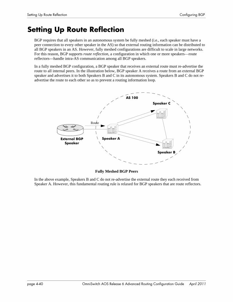
Setting Up Route Reflection Configuring BGP
Setting Up Route ReflectionBGP requires that all speakers in an autonomous system be fully meshed (i.e., each speaker must have a peer connection to every other speaker in the AS) so that external routing information can be distributed to all BGP speakers in an AS. However, fully meshed configurations are difficult to scale in large networks. For this reason, BGP supports route reflection, a configuration in which one or more speakers—route reflectors—handle intra-AS communication among all BGP speakers.
In a fully meshed BGP configuration, a BGP speaker that receives an external route must re-advertise the route to all internal peers. In the illustration below, BGP speaker A receives a route from an external BGP speaker and advertises it to both Speakers B and C in its autonomous system. Speakers B and C do not re-advertise the route to each other so as to prevent a routing information loop.
Fully Meshed BGP Peers
In the above example, Speakers B and C do not re-advertise the external route they each received from Speaker A. However, this fundamental routing rule is relaxed for BGP speakers that are route reflectors.
External BGPSpeaker
Speaker A
Speaker C
Speaker B
AS 100
Route
page 4-40 OmniSwitch AOS Release 6 Advanced Routing Configuration Guide April 2011
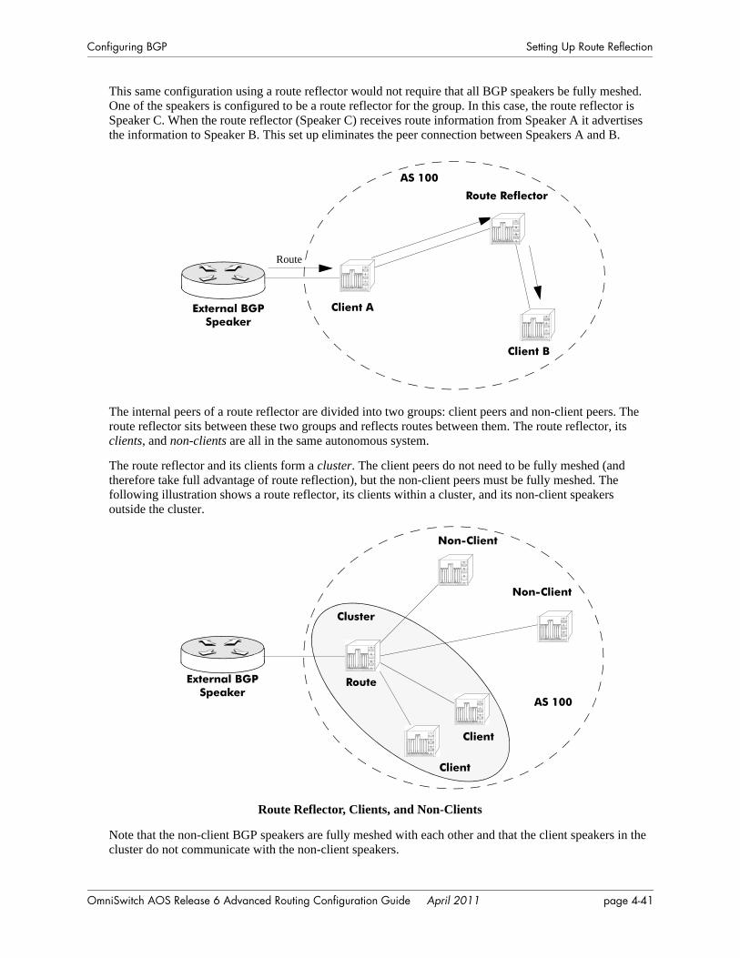
Configuring BGP Setting Up Route Reflection
This same configuration using a route reflector would not require that all BGP speakers be fully meshed. One of the speakers is configured to be a route reflector for the group. In this case, the route reflector is Speaker C. When the route reflector (Speaker C) receives route information from Speaker A it advertises the information to Speaker B. This set up eliminates the peer connection between Speakers A and B.
The internal peers of a route reflector are divided into two groups: client peers and non-client peers. The route reflector sits between these two groups and reflects routes between them. The route reflector, its clients, and non-clients are all in the same autonomous system.
The route reflector and its clients form a cluster. The client peers do not need to be fully meshed (and therefore take full advantage of route reflection), but the non-client peers must be fully meshed. The following illustration shows a route reflector, its clients within a cluster, and its non-client speakers outside the cluster.
Route Reflector, Clients, and Non-Clients
Note that the non-client BGP speakers are fully meshed with each other and that the client speakers in the cluster do not communicate with the non-client speakers.
External BGPSpeaker
Client A
Client B
AS 100
Route
Route Reflector
Cluster
Route
Client
Client
AS 100
Non-Client
External BGPSpeaker
Non-Client
OmniSwitch AOS Release 6 Advanced Routing Configuration Guide April 2011 page 4-41

Setting Up Route Reflection Configuring BGP
When a route reflector receives a route it, selects the best path based on its policy decision criteria. The internal peers to which the route reflector advertises depends on the source of the route. The table below shows the rules the reflector follows when advertising path information:
Configuring Route Reflection1 Disable the BGP protocol by specifying:
-> ip bgp status disable
2 Specify this router as a route reflector, using the ip bgp client-to-client reflection command:
-> ip bgp client-to-client reflection
The route reflector will follow the standard rules for client route advertisement (i.e., routes from a client are sent to all clients and non-clients, except the source client).
3 Indicate the client peers for this route reflector. For all internal peers (same AS as the router) that are to be clients specify the ip bgp neighbor route-reflector-client command. For example, if you wanted the peer at IP address 190.17.20.16 to become a client to the local BGP route-reflector, then you would spec-ify the following command:
-> ip bgp neighbor 190.17.20.16 route-reflector-client
4 Repeat Step 3 for all internal peers that are to be clients of the route reflector.
Redundant Route ReflectorsA single BGP speaker will usually act as the reflector for a cluster of clients. In such a case, the cluster is identified by the router ID of the reflector. It is possible to add redundancy to a cluster by configuring more than one route reflector, eliminating the single point of failure. Redundant route reflectors must be identified by a 4-byte cluster ID, which is specified in the ip bgp cluster-id command. All route reflectors in the same cluster must be fully meshed and should have the exact same client and non-client peers.
Note. Using many redundant reflectors is not recommended as it places demands on the memory required to store routes for all redundant reflectors’ peers.
To configure a redundant route reflector for this router, use the ip bgp cluster-id command. For example to set up a redundant route reflector at 190.17.21.16, you would enter:
-> ip bgp cluster-id 190.17.21.16
Route Received From... Route Advertised To...
External BGP Router All Clients and Non-Clients
Non-Client Peer All Clients
Client Peer All Clients and Non-Clients
page 4-42 OmniSwitch AOS Release 6 Advanced Routing Configuration Guide April 2011
Configuring BGP Working with Communities
Working with CommunitiesDistribution of routing information in BGP is typically based on IP address prefixes or on the value of the AS_PATH attributes. To facilitate and simplify the control of routing information, destinations can be grouped into communities and routing decisions can be applied based on these communities.
Communities are identified by using the numbering convention of the AS and the community number, separated by a colon (for example, 200:500)
There are a few well known communities defined (in RFC 1997) that do not require the numbering convention. Their community numbers are reserved and thus can be identified by name only. These are listed below:
• no-export. Routes in this community are advertised within the AS but not beyond the local AS.
• no-advertise. Routes in this community are not advertised to any peer.
• no-export-subconfed. Routes in this community are not advertised to any external BGP peer.
Communities are added to routes using the policy commands, as described in “Routing Policies” on page 4-45.
OmniSwitch AOS Release 6 Advanced Routing Configuration Guide April 2011 page 4-43
Creating a Confederation Configuring BGP
Creating a ConfederationA confederation is a grouping of ASs that together form a super AS. To BGP external peers, a confedera-tion appears as another AS even though the confederation has multiple ASs within it. Within a confedera-tion ASs can distinguish among one another and will advertise routes using EBGP.
1 Specify the confederation identifier for the local BGP router. This value is used to identify the confed-eration affiliation of routes in advertisements. This value is essentially an AS number. To assign a confed-eration number to the router use the ip bgp confederation identifier command. For example, to assign a confederation value of 2, you would enter:
-> ip bgp confederation-identifier 2
2 Indicate whether a peer belongs to the confederation configured on this router using theip bgp confederation neighbor command. For example to assign the peer at 190.17.20.16 to confedera-tion 2, you would enter:
-> ip bgp confederation neighbor 190.17.20.16
3 Repeat Step 2 for all peers that need to be assigned to the confederation.
page 4-44 OmniSwitch AOS Release 6 Advanced Routing Configuration Guide April 2011
Configuring BGP Routing Policies
Routing PoliciesBGP selects routes for subsequent advertisement by applying policies available in a pre-configured local Policy Information database. This support of policy-based routing provides flexibility by applying poli-cies based on the path (i.e. AS path list), community attributes (i.e. community lists), specific destinations (i.e. prefix lists), etc.
You could also configure route maps to include all of the above in a single policy.
For BGP to do policy-based routing, each BGP peer needs to be tied to inbound and/or outbound policies (direction based on whether routes are being learned or advertised). Each one of the above policies can be assigned as an in-bound or out-bound policy for a peer.
First, you must create policies that match one of the specified criteria:
• AS Paths. An AS path list notes all of the ASs the route travels to reach its destination.
• Community List. Communities can affect route behavior based on the definition of the community.
• Prefix List. Prefix list policies filter routes based on a specific network address, or a range of network addresses.
• Route Map. Route map policies filter routes by amalgamating other policies into one policy.
Then you must assign these policies to a peer. Policies can be assigned to affect routes learned from the peer, routes being advertised to the peer, or both.
Creating a PolicyThere are four different types of policies that can be created using the CLI, as described above. Each policy has several steps that must be implemented for a complete policy to be constructed. Minimally, the policy must be named, defined, and enabled.
The following sections describe the process of creating the four types of policies.
Creating an AS Path Policy
AS path policies must be assigned a name and a regular expression. Regular expressions are a set of symbols and characters that represent an AS or part of an AS path. Regular expressions are fully described in “Regular Expressions” on page 4-13.
To create an AS path policy:
1 Use the ip bgp policy aspath-list command, with a regular expression and a name, as shown:
-> ip bgp policy aspath-list aspathfilter “^100 200$”
This AS path policy is called aspathfilter. The policy looks for routes with an AS path with the next hop AS 100, and originating from AS 200. Regular expressions must be enclosed by quotes.
OmniSwitch AOS Release 6 Advanced Routing Configuration Guide April 2011 page 4-45
Routing Policies Configuring BGP
2 Next, use the ip bgp policy aspath-list action command to set the policy action. The action of a policy is whether the route filtered by the policy is permitted or denied. Denied routes are not propagated by the BGP speaker, while permitted routes are. For example:
-> ip bgp policy aspath-list aspathfilter “^100 200$” action permit
The AS path policy aspathfilter now permits routes that match the regular expression ^100 200$. Regular expressions must be enclosed by quotes.
3 Optionally, you can set the priority for routes filtered by the policy using the ip bgp policy aspath-list priority command. Priority for policies indicates which policy should be applied first to routes. Routes with a high priority number are applied first. To set the policy priority, enter the policy name with the priority number, as shown:
-> ip bgp policy aspath-list aspathfilter “^100 200$” priority 10
The AS path policy aspathfilter now has a priority of 10. Regular expressions must be enclosed by quotes.
Creating a Community List Policy
Community list policies must be assigned a name and a community number. Predetermined communities are specified in RFC 1997.
To create a community policy:
1 Assign a name and community number to the policy using the ip bgp policy community-list command, as shown:
-> ip bgp policy community-list commfilter 600:1
The policy name is commfilter and it looks for routes in the community 600:1.
2 Set the policy action using the ip bgp policy community-list action command. The policy action either permits or denies routes that match the filter. Permitted routes are advertised, while denied routes are not. For example:
-> ip bgp policy community-list commfilter 600:1 action permit
The commfilter policy now permits routes in community 600:1 to be advertised.
3 Set the policy match type using the ip bgp policy community-list match-type command. The match type can be set to either exact or occur. An exact match only affects routes that are solely in the specified community, while an occur match indicates that the community can be anywhere in the community list. For example:
-> ip bgp policy community-list commfilter 600:1 match-type exact
Policy commfilter now looks for routes that only belong to the community 600:1.
4 Optionally, you can set the priority for routes filtered by the policy using the ip bgp policy community-list priority command. Priority for policies indicates which policy should be applied first to routes. Routes with a high priority number are applied first. To set the policy priority, enter the policy name with the priority number, as shown:
-> ip bgp policy community-list commfilter 500:1 priority 3
Policy commfilter now has a priority of 3.
page 4-46 OmniSwitch AOS Release 6 Advanced Routing Configuration Guide April 2011

Configuring BGP Routing Policies
Creating a Prefix List Policy
Prefix policies filter routes based on network addresses and their masks. You can also set prefix upper and lower limits to filter a range of network addresses.
To create a prefix list policy:
1 Name the policy and specify the IP network address and mask using the ip bgp policy prefix-list command, as shown:
-> ip bgp policy prefix-list prefixfilter 12.0.0.0 255.0.0.0
Prefix policy prefixfilter now filters routes that match the network address 12.0.0.0 with a mask of 255.0.0.0.
2 Set the policy action using the ip bgp policy prefix-list action command. The policy action either permits or denies routes that match the filter. Permitted routes are advertised, while denied routes are not. For example:
-> ip bgp policy prefix-list prefixfilter 12.0.0.0 255.0.0.0 action deny
Prefix policy prefixfilter now denies routes that match the network address 12.0.0.0 with a mask of 255.0.0.0.
3 Optionally, you can set a lower prefix limit on the addresses specified in the policy using the ip bgp policy prefix-list ge command. For example:
-> ip bgp policy prefix-list prefixfilter 14.0.0.0 255.0.0.0 ge 16
Prefix policy prefixfilter now denies routes after 14.0.0.0/16.
4 Optionally, you can set an upper prefix limit on the addresses specified in the policy using the ip bgp policy prefix-list le command. For example:
-> ip bgp policy prefix-list prefixfilter 14.0.0.0 255.0.0.0 le 24
Prefix policy prefixfilter now denies routes between 14.0.0.0/16 and 14.0.0.0/24
Creating a Route Map Policy
Route map policies let you amalgamate the other policy types together, as well as add various other filters. For example, you could have a route map policy that includes both an AS path policy and a community policy.
To create a route map policy:
1 Name the route map policy and assign it a sequence number using the ip bgp policy route-map command. The sequence number allows for multiple instances of a policy, and orders the route map poli-cies so that a lower sequence number is applied first. For example:
-> ip bgp policy route-map mapfilter 1
Route map policy mapfilter is now ready.
OmniSwitch AOS Release 6 Advanced Routing Configuration Guide April 2011 page 4-47
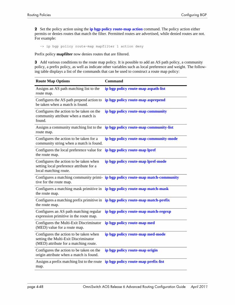
Routing Policies Configuring BGP
2 Set the policy action using the ip bgp policy route-map action command. The policy action either permits or denies routes that match the filter. Permitted routes are advertised, while denied routes are not. For example:
-> ip bgp policy route-map mapfilter 1 action deny
Prefix policy mapfilter now denies routes that are filtered.
3 Add various conditions to the route map policy. It is possible to add an AS path policy, a community policy, a prefix policy, as well as indicate other variables such as local preference and weight. The follow-ing table displays a list of the commands that can be used to construct a route map policy:
Route Map Options Command
Assigns an AS path matching list to the route map.
ip bgp policy route-map aspath-list
Configures the AS path prepend action to be taken when a match is found.
ip bgp policy route-map asprepend
Configures the action to be taken on the community attribute when a match is found.
ip bgp policy route-map community
Assigns a community matching list to the route map.
ip bgp policy route-map community-list
Configures the action to be taken for a community string when a match is found.
ip bgp policy route-map community-mode
Configures the local preference value for the route map.
ip bgp policy route-map lpref
Configures the action to be taken when setting local preference attribute for a local matching route.
ip bgp policy route-map lpref-mode
Configures a matching community primi-tive for the route map.
ip bgp policy route-map match-community
Configures a matching mask primitive in the route map.
ip bgp policy route-map match-mask
Configures a matching prefix primitive in the route map.
ip bgp policy route-map match-prefix
Configures an AS path matching regular expression primitive in the route map.
ip bgp policy route-map match-regexp
Configures the Multi-Exit Discriminator (MED) value for a route map.
ip bgp policy route-map med
Configures the action to be taken when setting the Multi-Exit Discriminator (MED) attribute for a matching route.
ip bgp policy route-map med-mode
Configures the action to be taken on the origin attribute when a match is found.
ip bgp policy route-map origin
Assigns a prefix matching list to the route map.
ip bgp policy route-map prefix-list
page 4-48 OmniSwitch AOS Release 6 Advanced Routing Configuration Guide April 2011
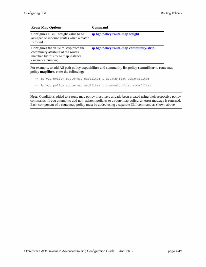
Configuring BGP Routing Policies
For example, to add AS path policy aspathfilter and community list policy commfilter to route map policy mapfilter, enter the following:
-> ip bgp policy route-map mapfilter 1 aspath-list aspathfilter
-> ip bgp policy route-map mapfilter 1 community-list commfilter
Note. Conditions added to a route map policy must have already been created using their respective policy commands. If you attempt to add non-existent policies to a route map policy, an error message is returned. Each component of a route map policy must be added using a separate CLI command as shown above.
Configures a BGP weight value to be assigned to inbound routes when a match is found.
ip bgp policy route-map weight
Configures the value to strip from the community attribute of the routes matched by this route map instance (sequence number).
ip bgp policy route-map community-strip
Route Map Options Command
OmniSwitch AOS Release 6 Advanced Routing Configuration Guide April 2011 page 4-49
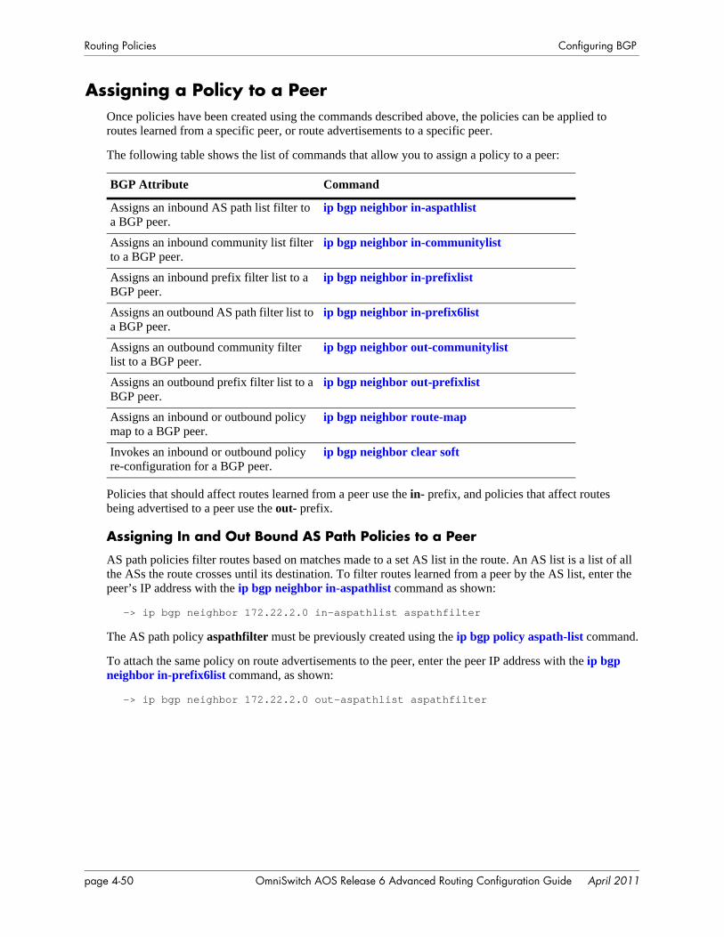
Routing Policies Configuring BGP
Assigning a Policy to a PeerOnce policies have been created using the commands described above, the policies can be applied to routes learned from a specific peer, or route advertisements to a specific peer.
The following table shows the list of commands that allow you to assign a policy to a peer:
Policies that should affect routes learned from a peer use the in- prefix, and policies that affect routes being advertised to a peer use the out- prefix.
Assigning In and Out Bound AS Path Policies to a Peer
AS path policies filter routes based on matches made to a set AS list in the route. An AS list is a list of all the ASs the route crosses until its destination. To filter routes learned from a peer by the AS list, enter the peer’s IP address with the ip bgp neighbor in-aspathlist command as shown:
-> ip bgp neighbor 172.22.2.0 in-aspathlist aspathfilter
The AS path policy aspathfilter must be previously created using the ip bgp policy aspath-list command.
To attach the same policy on route advertisements to the peer, enter the peer IP address with the ip bgp neighbor in-prefix6list command, as shown:
-> ip bgp neighbor 172.22.2.0 out-aspathlist aspathfilter
BGP Attribute Command
Assigns an inbound AS path list filter to a BGP peer.
ip bgp neighbor in-aspathlist
Assigns an inbound community list filter to a BGP peer.
ip bgp neighbor in-communitylist
Assigns an inbound prefix filter list to a BGP peer.
ip bgp neighbor in-prefixlist
Assigns an outbound AS path filter list to a BGP peer.
ip bgp neighbor in-prefix6list
Assigns an outbound community filter list to a BGP peer.
ip bgp neighbor out-communitylist
Assigns an outbound prefix filter list to a BGP peer.
ip bgp neighbor out-prefixlist
Assigns an inbound or outbound policy map to a BGP peer.
ip bgp neighbor route-map
Invokes an inbound or outbound policy re-configuration for a BGP peer.
ip bgp neighbor clear soft
page 4-50 OmniSwitch AOS Release 6 Advanced Routing Configuration Guide April 2011

Configuring BGP Routing Policies
Assigning In and Out Bound Community List Policies to a Peer
Community list policies filter routes based on matches made to a list of communities of which the route is a member. Communities group routes by attaching labels to them specifying a behavior (such as no export).
To filter routes learned from a peer by the community list, enter the peer’s IP address with the ip bgp neighbor in-communitylist command as shown:
-> ip bgp neighbor 172.22.2.0 in-communitylist commlistfilter
The community list policy commlistfilter must be previously created using the ip bgp policy community-list command.
To assign the same policy to route advertisements to the peer, enter the peer IP address with the ip bgp neighbor out-communitylist command, as shown:
-> ip bgp neighbor 172.22.2.0 out-communitylist commlistfilter
Assigning In and Out Bound Route Map Policies to a Peer
Route map policies filter routes combining routing criteria such as AS path, community, etc.
To filter routes learned from a peer by the route map, enter the peer’s IP address with the ip bgp neighbor route-map command as shown:
-> ip bgp neighbor 172.22.2.0 route-map mapfilter in
The route map policy mapfilter must be previously created using the ip bgp policy prefix6-list command.
To assign the same policy to route advertisements to the peer, enter the peer IP address with the ip bgp neighbor route-map command, as shown:
-> ip bgp neighbor 172.22.2.0 route-map mapfilter out
Assigning In and Out Bound Prefix List Policies to a Peer
Prefix list policies filter routes based on a specific routing network, using an IP address or a series of IP addresses.
To filter routes learned from a peer by the prefix list, enter the peer’s IP address with the ip bgp neighbor in-prefixlist command as shown:
-> ip bgp neighbor 172.22.2.0 in-prefixlist prefixfilter
The route map policy prefixfilter must be previously created using the ip bgp policy prefix-list command.
To assign the same policy to route advertisements to the peer, enter the peer IP address with the ip bgp neighbor out-prefixlist command, as shown:
-> ip bgp neighbor 172.22.2.0 in-prefixlist prefixfilter
OmniSwitch AOS Release 6 Advanced Routing Configuration Guide April 2011 page 4-51
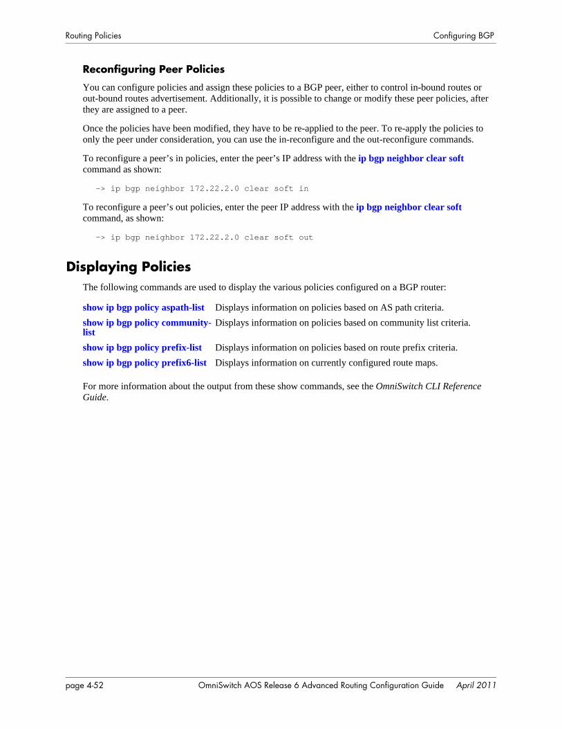
Routing Policies Configuring BGP
Reconfiguring Peer Policies
You can configure policies and assign these policies to a BGP peer, either to control in-bound routes or out-bound routes advertisement. Additionally, it is possible to change or modify these peer policies, after they are assigned to a peer.
Once the policies have been modified, they have to be re-applied to the peer. To re-apply the policies to only the peer under consideration, you can use the in-reconfigure and the out-reconfigure commands.
To reconfigure a peer’s in policies, enter the peer’s IP address with the ip bgp neighbor clear soft command as shown:
-> ip bgp neighbor 172.22.2.0 clear soft in
To reconfigure a peer’s out policies, enter the peer IP address with the ip bgp neighbor clear soft command, as shown:
-> ip bgp neighbor 172.22.2.0 clear soft out
Displaying PoliciesThe following commands are used to display the various policies configured on a BGP router:
For more information about the output from these show commands, see the OmniSwitch CLI Reference Guide.
show ip bgp policy aspath-list Displays information on policies based on AS path criteria.show ip bgp policy community-list
Displays information on policies based on community list criteria.
show ip bgp policy prefix-list Displays information on policies based on route prefix criteria.show ip bgp policy prefix6-list Displays information on currently configured route maps.
page 4-52 OmniSwitch AOS Release 6 Advanced Routing Configuration Guide April 2011
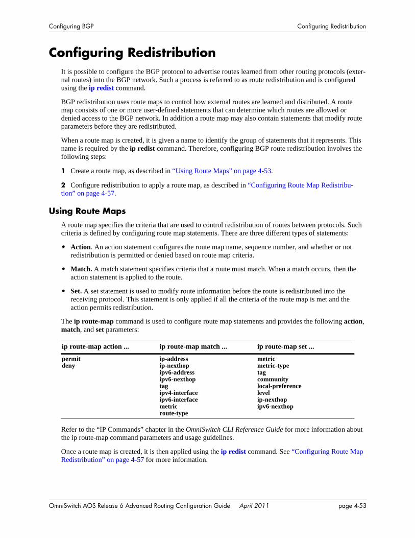
Configuring BGP Configuring Redistribution
Configuring RedistributionIt is possible to configure the BGP protocol to advertise routes learned from other routing protocols (exter-nal routes) into the BGP network. Such a process is referred to as route redistribution and is configured using the ip redist command.
BGP redistribution uses route maps to control how external routes are learned and distributed. A route map consists of one or more user-defined statements that can determine which routes are allowed or denied access to the BGP network. In addition a route map may also contain statements that modify route parameters before they are redistributed.
When a route map is created, it is given a name to identify the group of statements that it represents. This name is required by the ip redist command. Therefore, configuring BGP route redistribution involves the following steps:
1 Create a route map, as described in “Using Route Maps” on page 4-53.
2 Configure redistribution to apply a route map, as described in “Configuring Route Map Redistribu-tion” on page 4-57.
Using Route MapsA route map specifies the criteria that are used to control redistribution of routes between protocols. Such criteria is defined by configuring route map statements. There are three different types of statements:
• Action. An action statement configures the route map name, sequence number, and whether or not redistribution is permitted or denied based on route map criteria.
• Match. A match statement specifies criteria that a route must match. When a match occurs, then the action statement is applied to the route.
• Set. A set statement is used to modify route information before the route is redistributed into the receiving protocol. This statement is only applied if all the criteria of the route map is met and the action permits redistribution.
The ip route-map command is used to configure route map statements and provides the following action, match, and set parameters:
Refer to the “IP Commands” chapter in the OmniSwitch CLI Reference Guide for more information about the ip route-map command parameters and usage guidelines.
Once a route map is created, it is then applied using the ip redist command. See “Configuring Route Map Redistribution” on page 4-57 for more information.
ip route-map action ... ip route-map match ... ip route-map set ...
permitdeny
ip-addressip-nexthopipv6-addressipv6-nexthoptagipv4-interfaceipv6-interfacemetricroute-type
metricmetric-typetagcommunitylocal-preferencelevelip-nexthopipv6-nexthop
OmniSwitch AOS Release 6 Advanced Routing Configuration Guide April 2011 page 4-53
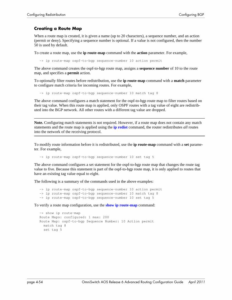
Configuring Redistribution Configuring BGP
Creating a Route Map
When a route map is created, it is given a name (up to 20 characters), a sequence number, and an action (permit or deny). Specifying a sequence number is optional. If a value is not configured, then the number 50 is used by default.
To create a route map, use the ip route-map command with the action parameter. For example,
-> ip route-map ospf-to-bgp sequence-number 10 action permit
The above command creates the ospf-to-bgp route map, assigns a sequence number of 10 to the route map, and specifies a permit action.
To optionally filter routes before redistribution, use the ip route-map command with a match parameter to configure match criteria for incoming routes. For example,
-> ip route-map ospf-to-bgp sequence-number 10 match tag 8
The above command configures a match statement for the ospf-to-bgp route map to filter routes based on their tag value. When this route map is applied, only OSPF routes with a tag value of eight are redistrib-uted into the BGP network. All other routes with a different tag value are dropped.
Note. Configuring match statements is not required. However, if a route map does not contain any match statements and the route map is applied using the ip redist command, the router redistributes all routes into the network of the receiving protocol.
To modify route information before it is redistributed, use the ip route-map command with a set parame-ter. For example,
-> ip route-map ospf-to-bgp sequence-number 10 set tag 5
The above command configures a set statement for the ospf-to-bgp route map that changes the route tag value to five. Because this statement is part of the ospf-to-bgp route map, it is only applied to routes that have an existing tag value equal to eight.
The following is a summary of the commands used in the above examples:
-> ip route-map ospf-to-bgp sequence-number 10 action permit-> ip route-map ospf-to-bgp sequence-number 10 match tag 8-> ip route-map ospf-to-bgp sequence-number 10 set tag 5
To verify a route map configuration, use the show ip route-map command:
-> show ip route-mapRoute Maps: configured: 1 max: 200Route Map: ospf-to-bgp Sequence Number: 10 Action permit match tag 8 set tag 5
page 4-54 OmniSwitch AOS Release 6 Advanced Routing Configuration Guide April 2011

Configuring BGP Configuring Redistribution
Deleting a Route Map
Use the no form of the ip route-map command to delete an entire route map, a route map sequence, or a specific statement within a sequence.
To delete an entire route map, enter no ip route-map followed by the route map name. For example, the following command deletes the entire route map named redistipv4:
-> no ip route-map redistipv4
To delete a specific sequence number within a route map, enter no ip route-map followed by the route map name, then sequence-number followed by the actual number. For example, the following command deletes sequence 10 from the redistipv4 route map:
-> no ip route-map redistipv4 sequence-number 10
Note that in the above example, the redistripv4 route map is not deleted. Only those statements associated with sequence 10 are removed from the route map.
To delete a specific statement within a route map, enter no ip route-map followed by the route map name, then sequence-number followed by the sequence number for the statement, then either match or set and the match or set parameter and value. For example, the following command deletes only the match tag 8 statement from route map redistipv4 sequence 10:
-> no ip route-map redistipv4 sequence-number 10 match tag 8
Configuring Route Map Sequences
A route map may consist of one or more sequences of statements. The sequence number determines which statements belong to which sequence and the order in which sequences for the same route map are processed.
To add match and set statements to an existing route map sequence, specify the same route map name and sequence number for each statement. For example, the following series of commands creates route map rm_1 and configures match and set statements for the rm_1 sequence 10:
-> ip route-map rm_1 sequence-number 10 action permit-> ip route-map rm_1 sequence-number 10 match tag 8-> ip route-map rm_1 sequence-number 10 set metric 1
To configure a new sequence of statements for an existing route map, specify the same route map name but use a different sequence number. For example, the following command creates a new sequence 20 for the rm_1 route map:
-> ip route-map rm_1 sequence-number 20 action permit-> ip route-map rm_1 sequence-number 20 match ipv4-interface to-finance-> ip route-map rm_1 sequence-number 20 set metric 5
The resulting route map appears as follows:
-> show ip route-map rm_1Route Map: rm_1 Sequence Number: 10 Action permit match tag 8 set metric 1Route Map: rm_1 Sequence Number: 20 Action permit match ip4 interface to-finance set metric 5
OmniSwitch AOS Release 6 Advanced Routing Configuration Guide April 2011 page 4-55
Configuring Redistribution Configuring BGP
Sequence 10 and sequence 20 are both linked to route map rm_1 and are processed in ascending order according to their sequence number value. Note that there is an implied logical OR between sequences. As a result, if there is no match for the tag value in sequence 10, then the match interface statement in sequence 20 is processed. However, if a route matches the tag 8 value, then sequence 20 is not used. The set statement for whichever sequence was matched is applied.
A route map sequence may contain multiple match statements. If these statements are of the same kind (e.g., match tag 5, match tag 8, etc.) then a logical OR is implied between each like statement. If the match statements specify different types of matches (e.g., match tag 5, match ip4 interface to-finance, etc.), then a logical AND is implied between each statement. For example, the following route map sequence will redistribute a route if its tag is either 8 or 5:
-> ip route-map rm_1 sequence-number 10 action permit-> ip route-map rm_1 sequence-number 10 match tag 5-> ip route-map rm_1 sequence-number 10 match tag 8
The following route map sequence will redistribute a route if the route has a tag of 8 or 5 and the route was learned on the IPv4 interface to-finance:
-> ip route-map rm_1 sequence-number 10 action permit-> ip route-map rm_1 sequence-number 10 match tag 5-> ip route-map rm_1 sequence-number 10 match tag 8-> ip route-map rm_1 sequence-number 10 match ipv4-interface to-finance
Configuring Access Lists
An IP access list provides a convenient way to add multiple IPv4 or IPv6 addresses to a route map. Using an access list avoids having to enter a separate route map statement for each individual IP address. Instead, a single statement is used that specifies the access list name. The route map is then applied to all the addresses contained within the access list.
Configuring an IP access list involves two steps: creating the access list and adding IP addresses to the list. To create an IP access list, use the ip access-list command (IPv4) or the ipv6 access-list command (IPv6) and specify a name to associate with the list. For example:
-> ip access-list ipaddr-> ipv6 access-list ip6addr
To add addresses to an access list, use the ip access-list address (IPv4) or the ipv6 access-list address (IPv6) command. For example, the following commands add addresses to an existing access list:
-> ip access-list ipaddr address 16.24.2.1/16-> ipv6 access-list ip6addr address 2001::1/64
Use the same access list name each time the above commands are used to add additional addresses to the same access list. In addition, both commands provide the ability to configure if an address and/or its matching subnet routes are permitted (the default) or denied redistribution. For example:
-> ip access-list ipaddr address 16.24.2.1/16 action deny redist-control all-subnets-> ipv6 access-list ip6addr address 2001::1/64 action permit redist-control no-subnets
For more information about configuring access list commands, see the “IP Commands” chapter in the OmniSwitch CLI Reference Guide.
page 4-56 OmniSwitch AOS Release 6 Advanced Routing Configuration Guide April 2011
Configuring BGP Configuring Redistribution
Configuring Route Map RedistributionThe ip redist command is used to configure the redistribution of routes from a source protocol into the BGP destination protocol. This command is used on the BGP router that will perform the redistribution.
A source protocol is a protocol from which the routes are learned. A destination protocol is the one into which the routes are redistributed. Make sure that both protocols are loaded and enabled before configur-ing redistribution.
Redistribution applies criteria specified in a route map to routes received from the source protocol. There-fore, configuring redistribution requires an existing route map. For example, the following command configures the redistribution of OSPF routes into the BGP network using the ospf-to-bgp route map:
-> ip redist ospf into bgp route-map ospf-to-bgp
OSPF routes received by the router interface are processed based on the contents of the ospf-to-bgp route map. Routes that match criteria specified in this route map are either allowed or denied redistribution into the BGP network. The route map may also specify the modification of route information before the route is redistributed. See “Using Route Maps” on page 4-53 for more information.
To remove a route map redistribution configuration, use the no form of the ip redist command. For exam-ple:
-> no ip redist ospf into bgp route-map ospf-to-bgp
Use the show ip redist command to verify the redistribution configuration:
-> show ip redist
Source DestinationProtocol Protocol Status Route Map------------+------------+---------+--------------------LOCAL4 RIP Enabled rip_1LOCAL4 OSPF Enabled ospf_2LOCAL4 BGP Enabled bgp_3RIP OSPF Enabled ospf-to-bgp
Configuring the Administrative Status of the Route Map Redistribution
The administrative status of a route map redistribution configuration is enabled by default. To change the administrative status, use the status parameter with the ip redist command. For example, the following command disables the redistribution administrative status for the specified route map:
-> ip redist ospf into bgp route-map ospf-to-bgp status disable
The following command example enables the administrative status:
-> ip redist ospf into rip route-map ospf-to-bgp status enable
OmniSwitch AOS Release 6 Advanced Routing Configuration Guide April 2011 page 4-57
Configuring Redistribution Configuring BGP
Route Map Redistribution ExampleThe following example configures the redistribution of OSPF routes into a BGP network using a route map (ospf-to-bgp) to filter specific routes:
-> ip route-map ospf-to-bgp sequence-number 10 action deny -> ip route-map ospf-to-bgp sequence-number 10 match tag 5-> ip route-map ospf-to-bgp sequence-number 10 match route-type external type2
-> ip route-map ospf-to-bgp sequence-number 20 action permit-> ip route-map ospf-to-bgp sequence-number 20 match ipv4-interface intf_ospf-> ip route-map ospf-to-bgp sequence-number 20 set metric 255
-> ip route-map ospf-to-bgp sequence-number 30 action permit-> ip route-map ospf-to-bgp sequence-number 30 set tag 8
-> ip redist ospf into bgp route-map ospf-to-bgp
The resulting ospf-to-bgp route map redistribution configuration does the following:
• Denies the redistribution of Type 2 external BGP routes with a tag set to five.
• Redistributes into BGP all routes learned on the intf_ospf interface and sets the metric for such routes to 255.
• Redistributes all other routes (those not processed by sequence 10 or 20) and sets the tag for such routes to eight.
page 4-58 OmniSwitch AOS Release 6 Advanced Routing Configuration Guide April 2011
Configuring BGP Configuring Redistribution
Configuring Redundant CMMs for Graceful RestartOn OmniSwitch devices in a redundant CMM configuration, during a CMM takeover/failover, inter-domain routing is disrupted. Alcatel-Lucent Operating System BGP needs to retain forwarding informa-tion, also help a peering router performing a BGP restart to support continuous forwarding for inter-domain traffic flows by following the BGP graceful restart mechanism.
By default, BGP graceful restart is enabled. To configure BGP graceful restart support on OmniSwitch switches, use the ip bgp graceful-restart command by entering ip bgp graceful-restart.
For example, to support BGP graceful restart, enter:
-> ip bgp graceful-restart
To configure the grace period (default is 90 seconds) for achieving a graceful BGP restart, use the ip bgp graceful-restart restart-interval command, followed by the value in seconds.
For example, to configure a BGP graceful restart grace period as 300 seconds, enter:
-> ip bgp graceful-restart restart-interval 60
To disable support for graceful restart, use the no form of the ip bgp graceful-restart command by enter-ing:
-> no ip bgp graceful-restart
For more information about graceful restart commands, see the “BGP Commands” chapter in the OmniSwitch CLI Reference Guide.
OmniSwitch AOS Release 6 Advanced Routing Configuration Guide April 2011 page 4-59
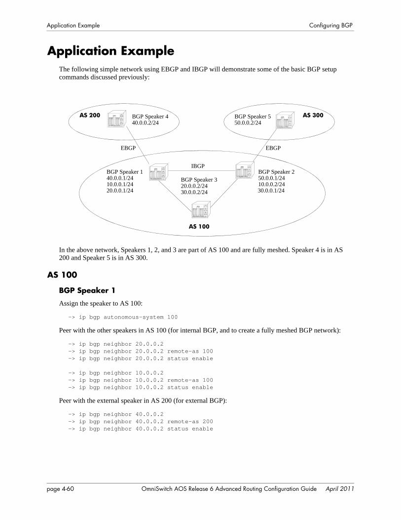
Application Example Configuring BGP
Application ExampleThe following simple network using EBGP and IBGP will demonstrate some of the basic BGP setup commands discussed previously:
In the above network, Speakers 1, 2, and 3 are part of AS 100 and are fully meshed. Speaker 4 is in AS 200 and Speaker 5 is in AS 300.
AS 100
BGP Speaker 1
Assign the speaker to AS 100:
-> ip bgp autonomous-system 100
Peer with the other speakers in AS 100 (for internal BGP, and to create a fully meshed BGP network):
-> ip bgp neighbor 20.0.0.2-> ip bgp neighbor 20.0.0.2 remote-as 100-> ip bgp neighbor 20.0.0.2 status enable
-> ip bgp neighbor 10.0.0.2-> ip bgp neighbor 10.0.0.2 remote-as 100-> ip bgp neighbor 10.0.0.2 status enable
Peer with the external speaker in AS 200 (for external BGP):
-> ip bgp neighbor 40.0.0.2-> ip bgp neighbor 40.0.0.2 remote-as 200-> ip bgp neighbor 40.0.0.2 status enable
BGP Speaker 320.0.0.2/2430.0.0.2/24
AS 100
AS 200 AS 300
EBGP EBGP
IBGP
BGP Speaker 440.0.0.2/24
BGP Speaker 550.0.0.2/24
BGP Speaker 140.0.0.1/2410.0.0.1/2420.0.0.1/24
BGP Speaker 250.0.0.1/2410.0.0.2/2430.0.0.1/24
page 4-60 OmniSwitch AOS Release 6 Advanced Routing Configuration Guide April 2011
Configuring BGP Application Example
Administratively enable BGP:
-> ip bgp status enable
BGP Speaker 2
Assign the speaker to AS 100:
-> ip bgp autonomous-system 100
Peer with the other speakers in AS 100 (for internal BGP, and to create a fully meshed BGP network):
-> ip bgp neighbor 30.0.0.2-> ip bgp neighbor 30.0.0.2 remote-as 100-> ip bgp neighbor 30.0.0.2 status enable
-> ip bgp neighbor 10.0.0.1-> ip bgp neighbor 10.0.0.1 remote-as 100-> ip bgp neighbor 10.0.0.1 status enable
Peer with the external speaker in AS 300 (for external BGP):
-> ip bgp neighbor 50.0.0.2-> ip bgp neighbor 50.0.0.2 remote-as 300-> ip bgp neighbor 50.0.0.2 status enable
Administratively enable BGP:
-> ip bgp status enable
BGP Speaker 3
Assign the speaker to AS 100:
-> ip bgp autonomous-system 100
Peer with the other speakers in AS 100 (for internal BGP, and to create a fully meshed BGP network):
-> ip bgp neighbor 30.0.0.1-> ip bgp neighbor 30.0.0.1 remote-as 100-> ip bgp neighbor 30.0.0.1 status enable
-> ip bgp neighbor 20.0.0.1-> ip bgp neighbor 20.0.0.1 remote-as 100-> ip bgp neighbor 20.0.0.1 status enable
Administratively enable BGP:
-> ip bgp status enable
AS 200
BGP Speaker 4
Assign the speaker to AS 200:
-> ip bgp as 200
OmniSwitch AOS Release 6 Advanced Routing Configuration Guide April 2011 page 4-61

Application Example Configuring BGP
Peer with the external speaker in AS 100 (for external BGP):
-> ip bgp neighbor 40.0.0.1-> ip bgp neighbor 40.0.0.1 remote-as 100-> ip bgp neighbor 40.0.0.1 status enable
Administratively enable BGP:
-> ip bgp status enable
AS 300
BGP Speaker 5
Assign the speaker to AS 300:
-> ip bgp autonomous-system 300
Peer with the external speaker in AS 100 (for external BGP):
-> ip bgp neighbor 50.0.0.1-> ip bgp neighbor 50.0.0.1 remote-as 100-> ip bgp neighbor 50.0.0.1 status enable
Administratively enable BGP:
-> ip bgp status enable
page 4-62 OmniSwitch AOS Release 6 Advanced Routing Configuration Guide April 2011
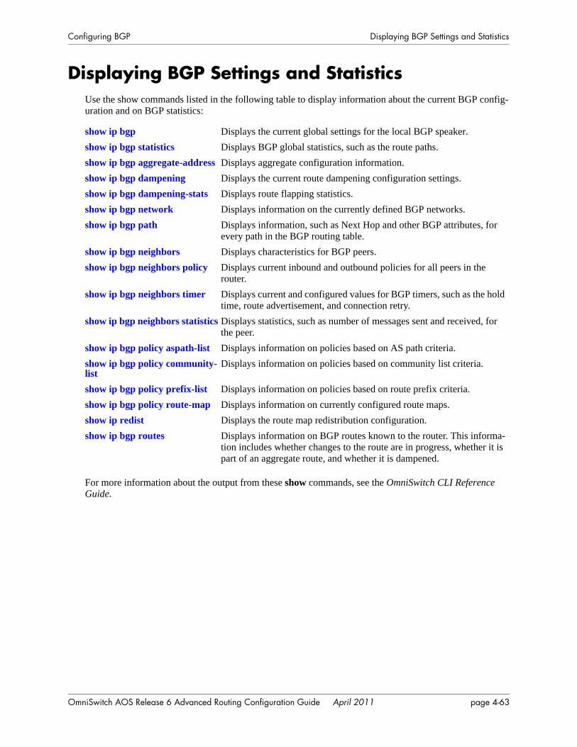
Configuring BGP Displaying BGP Settings and Statistics
Displaying BGP Settings and StatisticsUse the show commands listed in the following table to display information about the current BGP config-uration and on BGP statistics:
For more information about the output from these show commands, see the OmniSwitch CLI Reference Guide.
show ip bgp Displays the current global settings for the local BGP speaker.show ip bgp statistics Displays BGP global statistics, such as the route paths.show ip bgp aggregate-address Displays aggregate configuration information.show ip bgp dampening Displays the current route dampening configuration settings.show ip bgp dampening-stats Displays route flapping statistics.show ip bgp network Displays information on the currently defined BGP networks.show ip bgp path Displays information, such as Next Hop and other BGP attributes, for
every path in the BGP routing table.show ip bgp neighbors Displays characteristics for BGP peers.show ip bgp neighbors policy Displays current inbound and outbound policies for all peers in the
router.show ip bgp neighbors timer Displays current and configured values for BGP timers, such as the hold
time, route advertisement, and connection retry.show ip bgp neighbors statistics Displays statistics, such as number of messages sent and received, for
the peer.show ip bgp policy aspath-list Displays information on policies based on AS path criteria.show ip bgp policy community-list
Displays information on policies based on community list criteria.
show ip bgp policy prefix-list Displays information on policies based on route prefix criteria.show ip bgp policy route-map Displays information on currently configured route maps.show ip redist Displays the route map redistribution configuration.show ip bgp routes Displays information on BGP routes known to the router. This informa-
tion includes whether changes to the route are in progress, whether it is part of an aggregate route, and whether it is dampened.
OmniSwitch AOS Release 6 Advanced Routing Configuration Guide April 2011 page 4-63
BGP for IPv6 Overview Configuring BGP
BGP for IPv6 Overview IP version 6 (IPv6) is a new version of the Internet Protocol, designed as the successor to IP version 4 (IPv4), to overcome certain limitations in IPv4. IPv6 adds significant extra features that were not possible with IPv4. These include automatic configuration of hosts, extensive multicasting capabilities, and built-in security using authentication headers and encryption. Built-in support for QOS and path control are also features found in IPv6.
IPv6 is a hierarchical 128-bit addressing scheme that consists of 8 fields, comprising 16 bits each. An IPv6 address is written as a hexadecimal value (0-F) in groups of four, separated by colons. IPv6 provides 3x10^38 addresses, which can help overcome the shortage of IP addresses needed for internet usage.
There are three types of IPv6 addresses: Unicast, Anycast, and Multicast. A Unicast address identifies a single interface and a packet destined for a Unicast address is delivered to the interface identified by that address. An Anycast address identifies a set of interfaces and a packet destined for an Anycast address is delivered to the nearest interface identified by that Anycast address. A Multicast address identifies a set of interfaces and a packet destined for a Multicast address is delivered to all the interfaces identified by that Multicast address. There are no broadcast addresses in IPv6.
BGP uses Multiprotocol Extensions to support IPv6. The same procedures used for IPv4 prefixes can be applied for IPv6 prefixes as well and the exchange of IPv4 prefixes will not be affected by this new feature. However, there are some attributes that are specific to IPv4, such as AGGREGATOR, NEXT_HOP and NLRI. Multiprotocol Extensions for BGP also supports backward compatibility for the routers that do not support this feature. The OmniSwitch implementation supports Multiprotocol BGP as defined in the following RFCs: 4271, 2439, 3392, 2385, 1997, 4456, 3065, 4273, 4760, and 2545.
Note. Multiprotocol extensions for BGP-4 is supported with minimal or limited capability on OmniSwitch 6850 and 9000E Series switches.
To enable this implementation of BGP to support routing for multiple Network Layer protocols (e.g., IPv6, etc.), the following capabilities are added:
• Associating a particular Network Layer protocol with the next hop information.
• Associating a particular Network Layer protocol with NLRI.
To support Multiprotocol BGP Extensions, two new non-transitive attributes are introduced, Multiproto-col Reachable NLRI (MP_REACH_NLRI) and Multiprotocol Unreachable NLRI (MP_UNREACH_NLRI). MP_REACH_NLRI is utilized to carry the set of reachable destinations along with the next hop information to be used for these destinations. The MP_UNREACH_NLRI attribute carries the set of unreachable destinations.
Multiprotocol BGP extensions support the advertisement of IPv6 prefixes over the BGP sessions estab-lished between two BGP speakers using either of their IPv4 or IPv6 addresses. IPv6 prefixes can be redis-tributed into BGP using route maps. Similar to IPv4 networks, IPv6 networks should also be injected into BGP for a BGP speaker to advertise the network to its peers. A BGP speaker can support up to approxi-mately 5000 IPv6 prefixes.
Some features that are not supported in the current release of Multiprotocol BGP include:
• Route-Reflection capability.
• AS-Confederations capability.
• IPv6 route-flap dampening.
page 4-64 OmniSwitch AOS Release 6 Advanced Routing Configuration Guide April 2011

Configuring BGP BGP for IPv6 Overview
• IPv6 route aggregation.
• Policy-based route processing for IPv6 prefixes and peers.
• Routemap, prefix-list, community-list, and aspath-list policies.
• Graceful Restart capability for IPv6 prefixes.
• EBGP Multihop.
• Other multiprotocol capabilities for VPNs, MPLS label exchanges, etc.
OmniSwitch AOS Release 6 Advanced Routing Configuration Guide April 2011 page 4-65
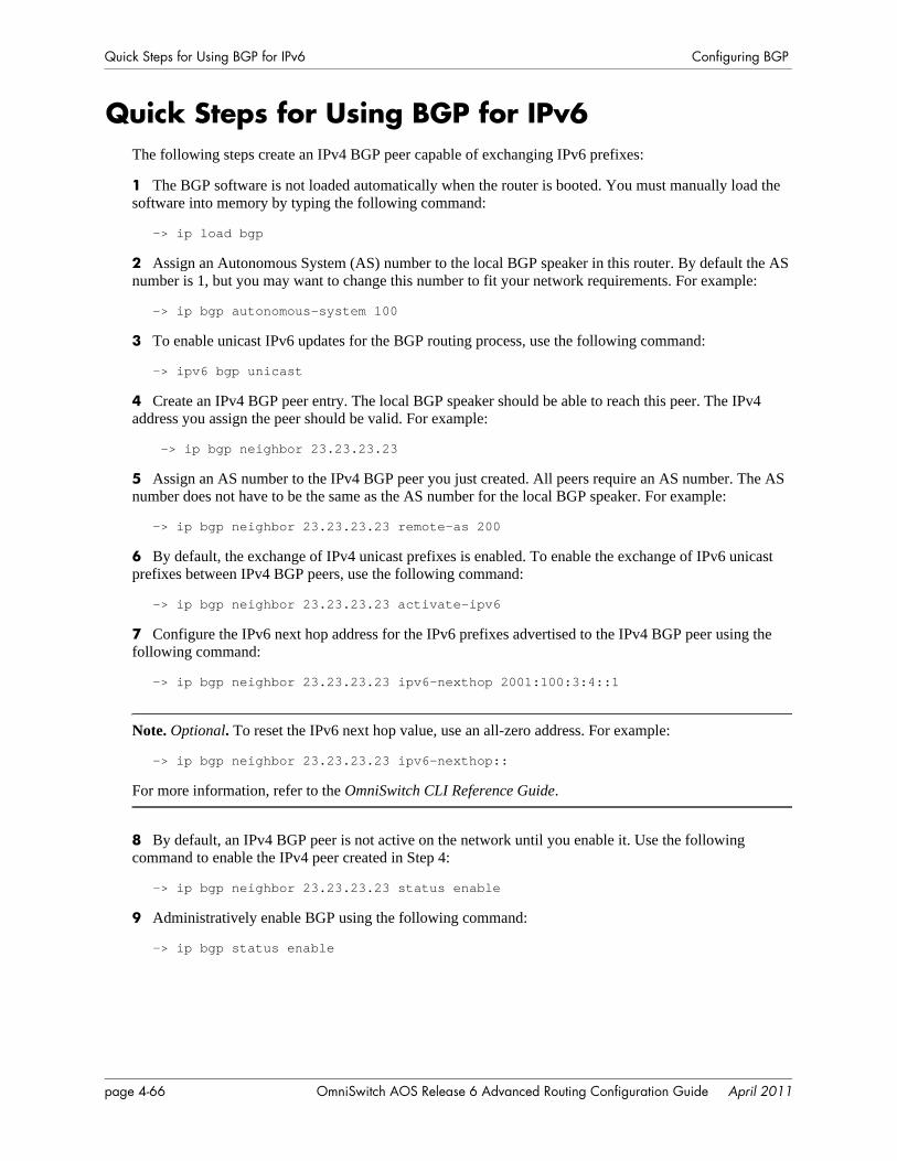
Quick Steps for Using BGP for IPv6 Configuring BGP
Quick Steps for Using BGP for IPv6The following steps create an IPv4 BGP peer capable of exchanging IPv6 prefixes:
1 The BGP software is not loaded automatically when the router is booted. You must manually load the software into memory by typing the following command:
-> ip load bgp
2 Assign an Autonomous System (AS) number to the local BGP speaker in this router. By default the AS number is 1, but you may want to change this number to fit your network requirements. For example:
-> ip bgp autonomous-system 100
3 To enable unicast IPv6 updates for the BGP routing process, use the following command:
-> ipv6 bgp unicast
4 Create an IPv4 BGP peer entry. The local BGP speaker should be able to reach this peer. The IPv4 address you assign the peer should be valid. For example:
-> ip bgp neighbor 23.23.23.23
5 Assign an AS number to the IPv4 BGP peer you just created. All peers require an AS number. The AS number does not have to be the same as the AS number for the local BGP speaker. For example:
-> ip bgp neighbor 23.23.23.23 remote-as 200
6 By default, the exchange of IPv4 unicast prefixes is enabled. To enable the exchange of IPv6 unicast prefixes between IPv4 BGP peers, use the following command:
-> ip bgp neighbor 23.23.23.23 activate-ipv6
7 Configure the IPv6 next hop address for the IPv6 prefixes advertised to the IPv4 BGP peer using the following command:
-> ip bgp neighbor 23.23.23.23 ipv6-nexthop 2001:100:3:4::1
Note. Optional. To reset the IPv6 next hop value, use an all-zero address. For example:
-> ip bgp neighbor 23.23.23.23 ipv6-nexthop::
For more information, refer to the OmniSwitch CLI Reference Guide.
8 By default, an IPv4 BGP peer is not active on the network until you enable it. Use the following command to enable the IPv4 peer created in Step 4:
-> ip bgp neighbor 23.23.23.23 status enable
9 Administratively enable BGP using the following command:
-> ip bgp status enable
page 4-66 OmniSwitch AOS Release 6 Advanced Routing Configuration Guide April 2011
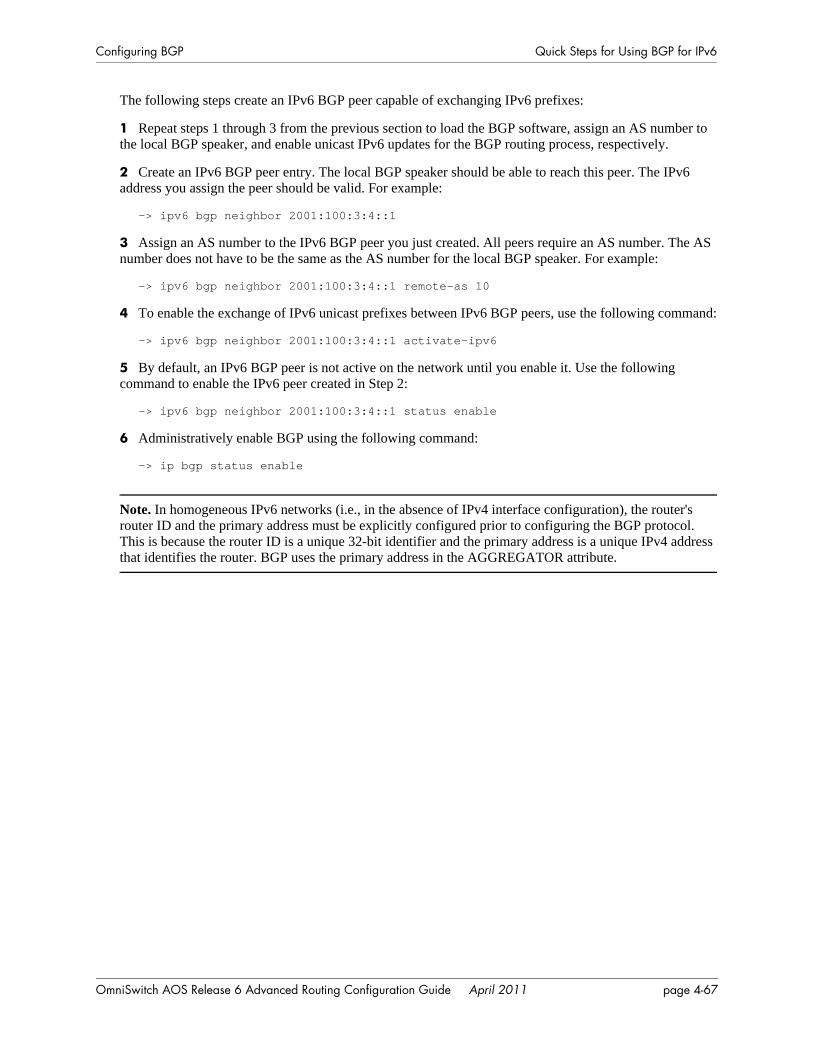
Configuring BGP Quick Steps for Using BGP for IPv6
The following steps create an IPv6 BGP peer capable of exchanging IPv6 prefixes:
1 Repeat steps 1 through 3 from the previous section to load the BGP software, assign an AS number to the local BGP speaker, and enable unicast IPv6 updates for the BGP routing process, respectively.
2 Create an IPv6 BGP peer entry. The local BGP speaker should be able to reach this peer. The IPv6 address you assign the peer should be valid. For example:
-> ipv6 bgp neighbor 2001:100:3:4::1
3 Assign an AS number to the IPv6 BGP peer you just created. All peers require an AS number. The AS number does not have to be the same as the AS number for the local BGP speaker. For example:
-> ipv6 bgp neighbor 2001:100:3:4::1 remote-as 10
4 To enable the exchange of IPv6 unicast prefixes between IPv6 BGP peers, use the following command:
-> ipv6 bgp neighbor 2001:100:3:4::1 activate-ipv6
5 By default, an IPv6 BGP peer is not active on the network until you enable it. Use the following command to enable the IPv6 peer created in Step 2:
-> ipv6 bgp neighbor 2001:100:3:4::1 status enable
6 Administratively enable BGP using the following command:
-> ip bgp status enable
Note. In homogeneous IPv6 networks (i.e., in the absence of IPv4 interface configuration), the router's router ID and the primary address must be explicitly configured prior to configuring the BGP protocol. This is because the router ID is a unique 32-bit identifier and the primary address is a unique IPv4 address that identifies the router. BGP uses the primary address in the AGGREGATOR attribute.
OmniSwitch AOS Release 6 Advanced Routing Configuration Guide April 2011 page 4-67
Configuring BGP for IPv6 Configuring BGP
Configuring BGP for IPv6This section describes the BGP for IPv6 configuration, which includes enabling and disabling IPv6 BGP unicast, configuring IPv6 BGP peers, and configuring IPv6 BGP networks using Alcatel-Lucent’s Command Line Interface (CLI) commands.
Enabling/Disabling IPv6 BGP UnicastBy default, BGP peers exchange only IPv4 unicast address prefixes. To exchange other address prefix types, such as IPv6 prefixes, you need to enable IPv6 unicast advertisements.
To enable IPv6 unicast updates, use the ipv6 bgp unicast command, as shown:
-> ipv6 bgp unicast
In a homogenous IPv6 network, you need to first disable the IPv4 unicast updates, and then enable the IPv6 unicast updates.
To disable IPv4 unicast updates, use the no form of the ipv6 bgp unicast command, as shown:
-> no ip bgp unicast
Now, you can enable IPv6 unicast updates.
However, in IPv6 environments where the BGP speakers have established peering using their IPv4 addresses, IPv4 unicasting may not be disabled.
Configuring an IPv6 BGP PeerA router configured to run the BGP routing protocol is called a BGP speaker. Unlike some other routing protocols, BGP speakers do not automatically discover each other and begin exchanging information. Instead, each BGP speaker must be explicitly configured with a set of BGP neighbors to exchange routing information. BGP is connection-oriented and uses TCP to establish a reliable connection. An underlying connection between two BGP speakers is established before any routing information is exchanged.
BGP supports two types of peers or neighbors, internal and external. Internal sessions run between BGP speakers in the same autonomous system. External sessions run between BGP peers in different autono-mous systems.
Every BGP speaker should be assigned to an AS. A BGP speaker can be configured as a peer within the same or different AS.
You can configure BGP speakers to exchange IPv6 prefixes using either their IPv4 or IPv6 addresses. By default, BGP speakers exchange only IPv4 unicast address prefixes. To exchange other address prefix types, such as IPv6 prefixes, BGP speakers must be activated to advertise IPv6 BGP prefixes.
BGP peering can be established using either IPv4 or IPv6 addresses. However, in the absence of IPv4 interface configuration, it is mandatory to explicitly configure the router's router ID and assign a unique IPv4 address as the router's primary address.
Note. In this document, the BGP terms “peer” and “neighbor” are used interchangeably to mean any BGP entity known to the local router.
page 4-68 OmniSwitch AOS Release 6 Advanced Routing Configuration Guide April 2011
Configuring BGP Configuring BGP for IPv6
BGP Peer Behavior using Local IPv6 Unicast Addresses
• The local IPv6 address prefixes are exchanged between internal BGP (IBGP) speakers within the same Autonomous System (AS), unless denied by explicit policy configuration.
• By default, Exterior BGP (EBGP) peers between different AS ignore receipt of and do not advertise prefixes with the well-known FC00::/7 prefix. Prefixes longer than FC00::/7 can be configured for inter-site communication.
• There may be specific /48 or longer routes created for one or more Local IPv6 prefixes. In such a case, explicit BGP configuration of peer policies must be configured to control learning/advertising of such prefixes.
Configuring an IPv4 BGP Peer to Exchange IPv6 Prefixes
A BGP peer that is identified by its IPv4 address can be used to exchange IPv6 prefixes. However, to do this both the peers should be enabled with IPv6 BGP unicast and should have interfaces that support IPv6 addresses. To configure an IPv4 BGP peer to exchange IPv6 prefixes, follow the steps mentioned below:
1 Create an IPv4 BGP peer with which the BGP speaker will establish peering using its IPv4 address with the ip bgp neighbor command, as shown:
-> ip bgp neighbor 190.17.20.16
2 Assign an AS number to the IPv4 peer using the ip bgp neighbor remote-as command. For example, to assign the peer created in Step 1 to AS number 200, you would enter:
-> ip bgp neighbor 190.17.20.16 remote-as 200
3 Enable IPv6 unicast capability for the IPv4 BGP peer using the ip bgp neighbor activate-ipv6 command, as shown:
-> ip bgp neighbor 190.17.20.16 activate-ipv6
4 Set the IPv6 next hop address for IPv6 prefixes advertised to the IPv4 BGP peer using the ip bgp neighbor ipv6-nexthop command, as shown:
-> ip bgp neighbor 190.17.20.16 ipv6-nexthop 2001::1
5 Enable the BGP peer status using the ip bgp neighbor status command. For example, to enable the status of the IPv4 BGP peer with an IPv4 address of 190.17.20.16, you would enter:
-> ip bgp neighbor 190.17.20.16 status enable
Configuring an IPv6 BGP Peer to Exchange IPv6 Prefixes
To configure an IPv6 BGP peer to exchange IPv6 prefixes, follow the steps mentioned below:
1 Create an IPv6 BGP peer with which the BGP speaker will establish peering using its IPv6 address with the ipv6 bgp neighbor command, as shown:
-> ipv6 bgp neighbor 2001::1
2 Assign an AS number to the IPv6 peer using the ipv6 bgp neighbor remote-as command. For exam-ple, to assign the peer created in Step 1 to AS number 10, you would enter:
-> ipv6 bgp neighbor 2001::1 remote-as 10
3 Enable IPv6 unicast capability for the IPv6 BGP peer using the ipv6 bgp neighbor clear soft command, as shown:
OmniSwitch AOS Release 6 Advanced Routing Configuration Guide April 2011 page 4-69
Configuring BGP for IPv6 Configuring BGP
-> ipv6 bgp neighbor 2001::1 activate-ipv6
4 Enable the BGP peer status using the ipv6 bgp neighbor status command. For example, to enable the status of the IPv6 BGP peer with an IPv6 address of 2001::1, you would enter:
-> ipv6 bgp neighbor 2001::1 status enable
Configuring an IPv6 BGP Peer Using Link-Local IPv6 Addresses to Exchange IPv6 Prefixes
To configure an IPv6 BGP peer using its link-local IPv6 address to exchange IPv6 prefixes, follow the steps mentioned below:
1 Create an IPv6 BGP peer with which the BGP speaker will establish peering using its link-local IPv6 address with the ipv6 bgp neighbor command, as shown:
-> ipv6 bgp neighbor fe80::2d0:95ff:fee2:6ed0
2 Assign an AS number to the IPv6 peer using the ipv6 bgp neighbor remote-as command. For exam-ple, to assign the peer created in Step 1 to AS number 20, you would enter:
-> ipv6 bgp neighbor fe80::2d0:95ff:fee2:6ed0 remote-as 20
3 Configure the local IPv6 interface from which the BGP peer will be reachable using the ipv6 bgp neighbor update-source command. For example, to configure Vlan2 as the IPv6 interface name from which the BGP peer is connected, you would enter:
-> ipv6 bgp neighbor fe80::2d0:95ff:fee2:6ed0 update-source Vlan2
4 Enable IPv6 unicast capability to the IPv6 BGP peer using the ipv6 bgp neighbor command, as shown:
-> ipv6 bgp neighbor fe80::2d0:95ff:fee2:6ed0 activate-ipv6
5 Enable the BGP peer status using the ipv6 bgp neighbor status command. For example, to enable the status of the BGP peer with a link-local IPv6 address of fe80::2d0:95ff:fee2:6ed0, you would enter,
-> ipv6 bgp neighbor fe80::2d0:95ff:fee2:6ed0 status enable
Configuring an IPv6 BGP Peer Using Globally Unique IPv6 Unicast Addresses
To configure an IPv6 BGP Unique IPv6 Unicast Addresses follow the steps mentioned below:
1 Create a prefix list for the well-known Unique IPv6 Unicast address using the ip bgp policy prefix6-list as shown:
-> ip bgp policy prefix6-list uniqLocal FC00::/48
-> ip bgp policy prefix6-list uniqLocal FC00::/48 action permit
-> ip bgp policy prefix6-list uniqLocal FC00::/48 status enable
2 Create an IPv6 BGP peer with which the BGP speaker will establish peering using the ipv6 bgp neigh-bor command, as shown:
-> ipv6 bgp neighbor 2021::10
3 Assign an AS number to the IPv6 peer using the ipv6 bgp neighbor remote-as command. For exam-ple, to assign the peer created in Step 2 to AS number 20, you would enter:
-> ipv6 bgp neighbor 2021::10 remote-as 20
page 4-70 OmniSwitch AOS Release 6 Advanced Routing Configuration Guide April 2011
Configuring BGP Configuring BGP for IPv6
4 Enable IPv6 unicast capability to the IPv6 BGP peer using the ipv6 bgp neighbor command, as shown:
-> ipv6 bgp neighbor 2021::10 activate-ipv6
5 Apply the policy to the bgp neighbor using the ipv6 bgp neighbor in-prefix6list and ipv6 bgp neigh-bor out-prefix6list commands as shown:
-> ipv6 bgp neighbor 2021::10 out-prefix6list uniqLocal
-> ipv6 bgp neighbor 2021::10 in-prefix6list uniqLocal
6 Enable the BGP peer status using the ipv6 bgp neighbor status command:
-> ipv6 bgp neighbor 2021::10 status enable
Configuring an IPv6 BGP peer to Exchange IPv4 Prefixes
A BGP peer that is identified by its IPv6 address can be used to exchange IPv4 prefixes. However, to do this, both peers should be enabled with IPv4 BGP unicast and should have interfaces that support IPv4 addresses. To configure an IPv6 BGP peer to exchange IPv4 prefixes, follow the steps mentioned below:
1 Create an IPv6 BGP peer with which the BGP speaker will establish peering using its IPv6 address with the ipv6 bgp neighbor command, as shown:
-> ipv6 bgp neighbor 2001::1
2 Assign an AS number to the IPv6 peer using the ipv6 bgp neighbor remote-as command. For exam-ple, to assign the peer created in Step 1 to AS number 10, you would enter:
-> ipv6 bgp neighbor 2001::1 remote-as 10
3 Set the IPv4 next hop address for IPv4 prefixes advertised to the IPv6 BGP peer using the ipv6 bgp neighbor ipv4-nexthop command, as shown:
-> ipv6 bgp neighbor 2001::1 ipv4-nexthop 190.17.20.1
4 Enable the BGP peer status using the ipv6 bgp neighbor status command, as shown:
-> ipv6 bgp neighbor 2001::1 status enable
Changing the Local Router Address for an IPv6 Peer SessionBy default, TCP connections to an IPv6 peer's address are assigned to the closest interface based on reach-ability. Any operational local IPv6 interface can be assigned to the IPv6 BGP peering session by explic-itly forcing the TCP connection to use the specified interface.
The ipv6 bgp neighbor update-source command sets the local IPv6 interface address or name through which this BGP peer can be contacted.
For example, to configure a peer with an IPv6 address of 2004::1 to be contacted via the IPv6 interface ipv6IntfVlan2, use the ipv6 bgp neighbor update-source command, as shown:
-> ipv6 bgp neighbor 2004::1 update-source ipv6IntfVlan2
Use the no form of the ipv6 bgp neighbor update-source command to prevent the peer with an IPv6 address of 2004::1 from contacting the speaker via the IPv6 interface ipv6IntfVlan2, as shown:
-> no ipv6 bgp neighbor 2004::1 update-source ipv6IntfVlan2
OmniSwitch AOS Release 6 Advanced Routing Configuration Guide April 2011 page 4-71
Configuring BGP for IPv6 Configuring BGP
Note. Alternatively, you can configure a peer with a link-local address of fe80::2d0:95ff:fee2:6ed0, using the ipv6 bgp neighbor update-source command, as shown below:
-> ipv6 bgp neighbor fe80::2d0:95ff:fee2:6ed0 update-source ipv6IntfVlan2
This command will establish a BGP peering session to establish neighborship.
Optional IPv6 BGP Peer Parameters
Configuring IPv6 BGP NetworksA local IPv6 BGP network is used to indicate to BGP that a network should originate from a specified router. A network must be known to the local BGP speaker and must also originate from the local BGP speaker.
Networks have certain parameters that can be configured, such as local-preference, community, metric, etc. Note that the network specified must be known to the router, whether it is connected, static, or dynam-ically learned. This is not the case for an aggregate.
Adding a NetworkTo add a local network to a BGP speaker, use the IPv6 address and mask of the local network in conjunc-tion with the ipv6 bgp network command, as shown:
-> ipv6 bgp network 2001::1/64
In this example, the network 2001::1/64 is the local IPv6 network for this BGP speaker.
Peer Parameter Command Default Value/Comments
The interval, in seconds, between BGP retries to set up a connection via the transport protocol with another peer.
ipv6 bgp neighbor conn-retry-interval
120 seconds
Enables or disables a BGP speaker to send a default route to its peer.
ipv6 bgp neighbor default-origi-nate
Disabled
Configures the KEEPALIVE message interval and hold time interval (in seconds) with regards to the specified BGP peer.
ipv6 bgp neighbor timers 30 seconds (keepalive)
90 seconds (holdtime)
Configures the maximum number of prefixes or paths the local router can receive from a BGP peer in UPDATE messages.
ipv6 bgp neighbor maximum-prefix
5000
Configures the local IPv6 interface from which a BGP peer will be connected.
ipv6 bgp neighbor update-source
Not set until con-figured
Configures router to advertise its peering address as the next hop address for the speci-fied neighbor.
ipv6 bgp neighbor next-hop-self Disabled
page 4-72 OmniSwitch AOS Release 6 Advanced Routing Configuration Guide April 2011
Configuring BGP Configuring BGP for IPv6
To remove the same network from the BGP speaker, use the no form of the ipv6 bgp network command, as shown:
-> no ipv6 bgp network 2001::1/64
The network will now no longer be associated as the local network for the BGP speaker.
Enabling a NetworkOnce the network has been added to the speaker, it must be enabled on the speaker. To do this, enter the IPv6 address and mask of the local network in conjunction with the ipv6 bgp network status command, as shown:
-> ipv6 bgp network 2001::1/64 status enable
In this example, the IPv6 network 2001::1/64 has now been enabled.
To disable the same network, enter the ipv6 bgp network status command, as shown:
-> ipv6 bgp network 2001::1/64 status disable
The network would now be disabled, though not removed from the speaker.
Configuring Network ParametersOnce a local IPv6 network is added to a speaker, you can configure three parameters that are attached to routes generated by the ipv6 bgp network command. These three attributes are the local preference, community, and route metric.
Local Preference
Local preference is an attribute that specifies the degree of preference to be given to a specific route when there are multiple routes to the same destination. This attribute is propagated throughout the autonomous system and is represented by a numeric value. The higher the number, the higher the preference. For example, a route with two exits, one with a local preference of 50 and another with a local preference 30 will use the path which has the local preference of 50.
To set the local preference for the local network, enter the IPv6 address and mask of the local network in conjunction with the ipv6 bgp network local-preference command and value, as shown:
-> ipv6 bgp network 2001::1/64 local-preference 600
The local preference for routes generated by the network is now 600. The default value is 0 (no network local preference is set).
Community
Communities are a way of grouping BGP destination addresses that share some common property. Adding the local network to a specific community indicates that the network shares a common set of properties with the rest of the community.
To add a network to a community, enter the local network IPv6 address and mask in conjunction with the ipv6 bgp network community command and name, as shown:
-> ipv6 bgp network 2001::1/64 community 100:200
Network 2001::1/64 is now in the 100:200 community. The default community is no community.
OmniSwitch AOS Release 6 Advanced Routing Configuration Guide April 2011 page 4-73
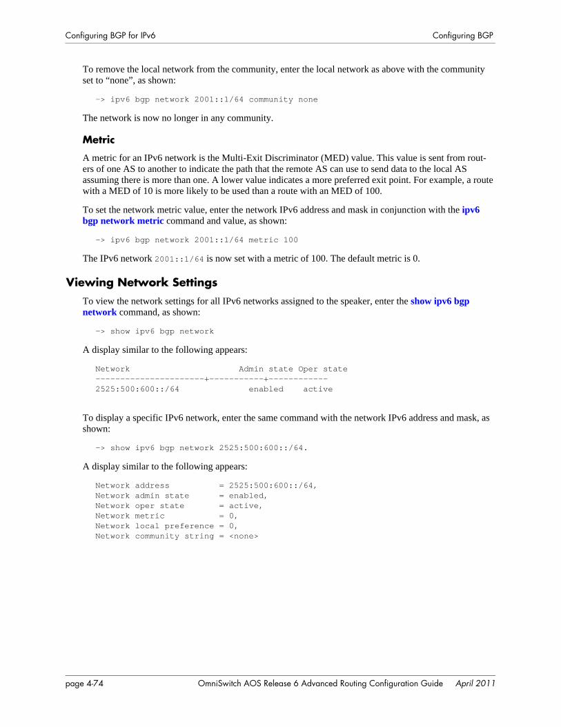
Configuring BGP for IPv6 Configuring BGP
To remove the local network from the community, enter the local network as above with the community set to “none”, as shown:
-> ipv6 bgp network 2001::1/64 community none
The network is now no longer in any community.
Metric
A metric for an IPv6 network is the Multi-Exit Discriminator (MED) value. This value is sent from rout-ers of one AS to another to indicate the path that the remote AS can use to send data to the local AS assuming there is more than one. A lower value indicates a more preferred exit point. For example, a route with a MED of 10 is more likely to be used than a route with an MED of 100.
To set the network metric value, enter the network IPv6 address and mask in conjunction with the ipv6 bgp network metric command and value, as shown:
-> ipv6 bgp network 2001::1/64 metric 100
The IPv6 network 2001::1/64 is now set with a metric of 100. The default metric is 0.
Viewing Network SettingsTo view the network settings for all IPv6 networks assigned to the speaker, enter the show ipv6 bgp network command, as shown:
-> show ipv6 bgp network
A display similar to the following appears:
Network Admin state Oper state----------------------+-----------+------------2525:500:600::/64 enabled active
To display a specific IPv6 network, enter the same command with the network IPv6 address and mask, as shown:
-> show ipv6 bgp network 2525:500:600::/64.
A display similar to the following appears:
Network address = 2525:500:600::/64,Network admin state = enabled,Network oper state = active,Network metric = 0,Network local preference = 0,Network community string = <none>
page 4-74 OmniSwitch AOS Release 6 Advanced Routing Configuration Guide April 2011
Configuring BGP Configuring IPv6 Redistribution
Configuring IPv6 RedistributionIt is possible to learn and advertise IPv6 routes between different routing protocols. Such a process is referred to as route redistribution and is configured using the ipv6 redist command.
IPv6 redistribution uses route maps to control how external routes are learned and distributed. A route map consists of one or more user-defined statements that can determine which routes are allowed or denied access to the network. In addition, a route map may also contain statements that modify route parameters before they are redistributed.
When a route map is created, it is given a name to identify the group of statements that it represents. This name is required by the ipv6 redist command. Therefore, configuring IPv6 BGP route redistribution involves the following steps:
1 Create a route map, as described in “Using Route Maps for IPv6 Redistribution” on page 4-75.
2 Configure IPv6 redistribution to apply a route map, as described in “Configuring IPv6 Route Map Redistribution” on page 4-75.
Using Route Maps for IPv6 RedistributionA route map specifies the criteria that are used to control redistribution of routes between protocols. Route maps that are used for redistributing both IPv4 and IPv6 routes are created in the same way. Refer to “Using Route Maps” on page 4-53 for more information.
Configuring IPv6 Route Map RedistributionOnce a route map is created, it is then applied using the ipv6 redist command. The ipv6 redist command is used to configure the redistribution of routes from a source protocol into the IPv6 BGP destination protocol. This command is used on the IPv6 BGP router that will perform the redistribution.
A source protocol is a protocol from which the routes are learned. A destination protocol is the one into which the routes are redistributed. Make sure that both protocols are loaded and enabled before configur-ing redistribution.
Redistribution applies criteria specified in a route map to routes received from the source protocol. There-fore, configuring redistribution requires an existing route map. For example, the following command configures the redistribution of OSPFv3 routes into the IPv6 BGP network using the ospf-to-bgp route map:
-> ipv6 redist ospf into bgp route-map ospf-to-bgp
OSPFv3 routes received by the router interface are processed based on the contents of the ospf-to-bgp route map. Routes that match criteria specified in this route map are either allowed or denied redistribu-tion into the IPv6 BGP network. The route map may also specify the modification of route information before the route is redistributed. See “Using Route Maps” on page 4-53 for more information.
To remove a route map redistribution configuration, use the no form of the ipv6 redist command. For example:
-> no ipv6 redist ospf into bgp route-map ospf-to-bgp
OmniSwitch AOS Release 6 Advanced Routing Configuration Guide April 2011 page 4-75
Configuring IPv6 Redistribution Configuring BGP
Use the show ipv6 redist command to verify the redistribution configuration:
-> show ipv6 redist
Source DestinationProtocol Protocol Status Route Map------------+------------+---------+--------------------localIPv6 BGP Enabled ipv6rmOSPFv3 RIPng Enabled ospf-to-rip
Configuring the Administrative Status of the Route Map Redistribution
The administrative status of a route map redistribution configuration is enabled by default. To change the administrative status, use the status parameter with the ipv6 redist command. For example, the following command disables the redistribution administrative status for the specified route map:
-> ipv6 redist ospf into bgp route-map ospf-to-bgp status disable
The following command example enables the administrative status:
-> ipv6 redist ospf into bgp route-map ospf-to-bgp status enable
Route Map Redistribution Example
The following example configures the redistribution of OSPFv3 routes into an IPv6 BGP network using a route map (ospf-to-bgp) to filter specific routes:
-> ip route-map ospf-to-bgp sequence-number 10 action deny -> ip route-map ospf-to-bgp sequence-number 10 match tag 5-> ip route-map ospf-to-bgp sequence-number 10 match route-type external type2
-> ip route-map ospf-to-bgp sequence-number 20 action permit-> ip route-map ospf-to-bgp sequence-number 20 match ipv6-interface intf_ospf-> ip route-map ospf-to-bgp sequence-number 20 set metric 255
-> ip route-map ospf-to-bgp sequence-number 30 action permit-> ip route-map ospf-to-bgp sequence-number 30 set tag 8
-> ipv6 redist ospf into bgp route-map ospf-to-bgp
The resulting ospf-to-bgp route map redistribution configuration does the following:
• Denies the redistribution of Type 2 external OSPFv3 routes with a tag set to five.
• Redistributes into IPv6 BGP all routes learned on the intf_ospf interface and sets the metric for such routes to 255.
• Redistributes into IPv6 BGP all other routes (those not processed by sequence 10 or 20) and sets the tag for such routes to eight.
page 4-76 OmniSwitch AOS Release 6 Advanced Routing Configuration Guide April 2011
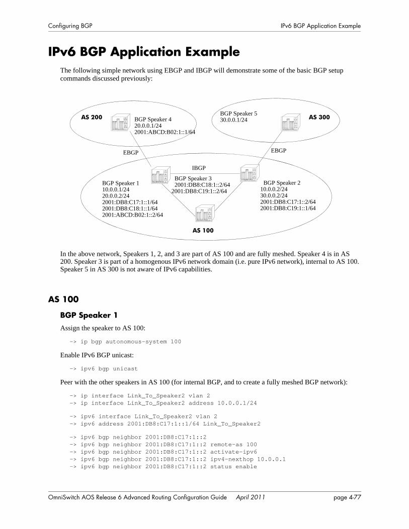
Configuring BGP IPv6 BGP Application Example
IPv6 BGP Application Example The following simple network using EBGP and IBGP will demonstrate some of the basic BGP setup commands discussed previously:
In the above network, Speakers 1, 2, and 3 are part of AS 100 and are fully meshed. Speaker 4 is in AS 200. Speaker 3 is part of a homogenous IPv6 network domain (i.e. pure IPv6 network), internal to AS 100. Speaker 5 in AS 300 is not aware of IPv6 capabilities.
AS 100
BGP Speaker 1
Assign the speaker to AS 100:
-> ip bgp autonomous-system 100
Enable IPv6 BGP unicast:
-> ipv6 bgp unicast
Peer with the other speakers in AS 100 (for internal BGP, and to create a fully meshed BGP network):
-> ip interface Link_To_Speaker2 vlan 2-> ip interface Link_To_Speaker2 address 10.0.0.1/24
-> ipv6 interface Link_To_Speaker2 vlan 2-> ipv6 address 2001:DB8:C17:1::1/64 Link_To_Speaker2
-> ipv6 bgp neighbor 2001:DB8:C17:1::2-> ipv6 bgp neighbor 2001:DB8:C17:1::2 remote-as 100-> ipv6 bgp neighbor 2001:DB8:C17:1::2 activate-ipv6-> ipv6 bgp neighbor 2001:DB8:C17:1::2 ipv4-nexthop 10.0.0.1-> ipv6 bgp neighbor 2001:DB8:C17:1::2 status enable
BGP Speaker 32001:DB8:C18:1::2/64
2001:DB8:C19:1::2/64
AS 100
AS 200 AS 300
EBGP EBGP
IBGP
BGP Speaker 530.0.0.1/24
BGP Speaker 110.0.0.1/2420.0.0.2/242001:DB8:C17:1::1/642001:DB8:C18:1::1/642001:ABCD:B02:1::2/64
BGP Speaker 210.0.0.2/2430.0.0.2/242001:DB8:C17:1::2/642001:DB8:C19:1::1/64
BGP Speaker 420.0.0.1/242001:ABCD:B02:1::1/64
OmniSwitch AOS Release 6 Advanced Routing Configuration Guide April 2011 page 4-77

IPv6 BGP Application Example Configuring BGP
-> ipv6 interface Link_To_Speaker3 vlan 3-> ipv6 address 2001:DB8:C18:1::1/64 Link_To_Speaker3-> ipv6 bgp neighbor 2001:DB8:C18:1::2-> ipv6 bgp neighbor 2001:DB8:C18:1::2 remote-as 100-> ipv6 bgp neighbor 2001:DB8:C18:1::2 activate-ipv6-> ipv6 bgp neighbor 2001:DB8:C18:1::2 status enable
Peer with the external speaker in AS 200 using its IPv4 address and an IPv6 forwarding interface (for IPv6 traffic):
-> ip interface Link_To_AS200 vlan 4-> ip interface Link_To_AS200 address 20.0.0.2/24
-> ipv6 interface Link_to_AS200 vlan 4-> ipv6 address 2001:ABCD:B02:1::2/64 Link_to_AS200
-> ip bgp neighbor 20.0.0.1-> ip bgp neighbor 20.0.0.1 remote-as 200-> ip bgp neighbor 20.0.0.1 activate-ipv6-> ip bgp neighbor 20.0.0.1 ipv6-nexthop 2001:ABCD:B02:1::2-> ip bgp neighbor 20.0.0.1 status enable
Administratively enable BGP:
-> ip bgp status enable
BGP Speaker 2
Assign the speaker to AS 100:
-> ip bgp autonomous-system 100
Enable IPv6 BGP unicast:
-> ipv6 bgp unicast
Peer with the other speakers in AS 100 (for internal BGP, and to create a fully meshed BGP network):
-> ip interface Link_To_Speaker1 vlan 2-> ip interface Link_To_Speaker1 address 10.0.0.2/24
-> ipv6 interface Link_To_Speaker1 vlan 2-> ipv6 address 2001:DB8:C17:1::2/64 Link_To_Speaker1
-> ipv6 bgp neighbor 2001:DB8:C17:1::1-> ipv6 bgp neighbor 2001:DB8:C17:1::1 remote-as 100-> ipv6 bgp neighbor 2001:DB8:C17:1::1 activate-ipv6-> ipv6 bgp neighbor 2001:DB8:C17:1::1 ipv4-nexthop 10.0.0.2-> ipv6 bgp neighbor 2001:DB8:C17:1::1 status enable
-> ipv6 interface Link_To_Speaker3 vlan 3-> ipv6 address 2001:DB8:C19:1::1/64 Link_To_Speaker3
-> ipv6 bgp neighbor 2001:DB8:C19:1::2-> ipv6 bgp neighbor 2001:DB8:C19:1::2 remote-as 100-> ipv6 bgp neighbor 2001:DB8:C19:1::2 activate-ipv6-> ipv6 bgp neighbor 2001:DB8:C19:1::2 status enable
page 4-78 OmniSwitch AOS Release 6 Advanced Routing Configuration Guide April 2011
Configuring BGP IPv6 BGP Application Example
Peer with the external speaker in AS 300 using IPv4 address:
-> ip interface Link_To_AS300 vlan 4-> ip interface Link_To_AS300 address 30.0.0.2/24
-> ip bgp neighbor 30.0.0.1-> ip bgp neighbor 30.0.0.1 remote-as 300-> ip bgp neighbor 30.0.0.1 status enable
Administratively enable BGP:
-> ip bgp status enable
BGP Speaker 3
Assign the speaker to AS 100:
-> ip bgp autonomous-system 100
Administratively disable IPv4 unicast, as this speaker is part of a homogeneous IPv6 domain:
-> no ip bgp unicast
Explicitly configure the router ID and the primary address of the speaker:
-> ip router router-id 10.0.0.3-> ip router primary-address 10.0.0.3
Peer with the other speakers in AS 100 (for internal BGP, and to create a fully meshed BGP network):
-> ipv6 interface Link_To_Speaker1 vlan 2-> ipv6 address 2001:DB8:C18:1::2/64 Link_To_Speaker1
-> ipv6 interface Link_To_Speaker2 vlan 3-> ipv6 address 2001:DB8:C19:1::2/64 Link_To_Speaker2
-> ipv6 bgp neighbor address 2001:DB8:C18:1::1-> ipv6 bgp neighbor address 2001:DB8:C18:1::1 remote-as 100-> ipv6 bgp neighbor address 2001:DB8:C18:1::1 activate-ipv6-> ipv6 bgp neighbor address 2001:DB8:C18:1::1 status enable
-> ipv6 bgp neighbor address 2001:DB8:C19:1::1-> ipv6 bgp neighbor address 2001:DB8:C19:1::1 remote-as 100-> ipv6 bgp neighbor address 2001:DB8:C19:1::1 activate-ipv6-> ipv6 bgp neighbor address 2001:DB8:C19:1::1 status enable
Administratively enable BGP:
-> ip bgp status enable
AS 200
BGP Speaker 4
Assign the speaker to AS 200:
-> ip bgp autonomous-system 200
Enable IPv6 BGP unicast:
-> ipv6 bgp unicast
OmniSwitch AOS Release 6 Advanced Routing Configuration Guide April 2011 page 4-79
IPv6 BGP Application Example Configuring BGP
Peer with the external speaker in AS 100 using its IPv4 address and an IPv6 forwarding interface (for IPv6 traffic):
-> ip interface Link_To_AS100 vlan 2-> ip interface Link_To_AS100 address 20.0.0.1/24
-> ipv6 interface Link_to_AS100 vlan 2-> ipv6 address 2001:ABCD:B02:1::1/64 Link_to_AS100
-> ip bgp neighbor 20.0.0.2-> ip bgp neighbor 20.0.0.2 remote-as 100-> ip bgp neighbor 20.0.0.2 activate-ipv6-> ip bgp neighbor 20.0.0.2 ipv6-nexthop 2001:ABCD:B02:1::1-> ip bgp neighbor 20.0.0.2 status enable
Administratively enable BGP:
-> ip bgp status enable
AS 300
BGP Speaker 5
Assign the speaker to AS 300:
-> ip bgp autonomous-system 300
Peer with the external speaker in AS 100 using its IPv4 address:
-> ip interface Link_To_AS100 vlan 2-> ip interface Link_To_AS100 address 30.0.0.1/24
-> ip bgp neighbor 30.0.0.2-> ip bgp neighbor 30.0.0.2 remote-as 100-> ip bgp neighbor 30.0.0.2 status enable
Administratively enable BGP:
-> ip bgp status enable
page 4-80 OmniSwitch AOS Release 6 Advanced Routing Configuration Guide April 2011

Configuring BGP Displaying IPv6 BGP Settings and Statistics
Displaying IPv6 BGP Settings and StatisticsUse the show commands listed in the following table to display information about the current IPv6 BGP configuration and on IPv6 BGP statistics:
For more information about the output from these show commands, see the OmniSwitch CLI Reference Guide.
show ipv6 bgp network Displays the status of all the IPv6 BGP networks or a specific IPv6 BGP network.
show ipv6 bgp path Displays the known IPv6 BGP paths for all the routes or a specific route.show ipv6 bgp routes Displays the known IPv6 BGP routes.show ipv6 bgp neighbors Displays the configured IPv6 BGP peers.show ipv6 bgp neighbors timers
Displays the timers for configured IPv6 BGP peers.
show ipv6 bgp neighbors statistics
Displays the neighbor statistics of the configured IPv6 BGP peers.
show ip bgp Displays the current global settings for the local BGP speaker.show ip bgp neighbors Displays the configured IPv4 BGP peers.
OmniSwitch AOS Release 6 Advanced Routing Configuration Guide April 2011 page 4-81

Displaying IPv6 BGP Settings and Statistics Configuring BGP
page 4-82 OmniSwitch AOS Release 6 Advanced Routing Configuration Guide April 2011
5 Configuring MulticastAddress Boundaries
Multicast boundaries confine scoped multicast addresses to a particular domain. Confining scoped addresses helps to ensure that multicast traffic passed within a multicast domain does not conflict with multicast users outside the domain.
In This ChapterThis chapter describes the basic components of scoped multicast boundaries and how to configure them through the Command Line Interface (CLI). CLI commands are used in the configuration examples; for more details about the syntax of commands, see the OmniSwitch CLI Reference Guide.
Configuration procedures described in this chapter include:
• Configuring multicast address boundaries—see page 5-7.
• Verifying the multicast address boundary configuration—see page 5-8.
For information about additional multicast routing commands, see the “Multicast Routing Commands” chapter in the OmniSwitch CLI Reference Guide.
OmniSwitch AOS Release 6 Advanced Routing Configuration Guide April 2011 page 5-1
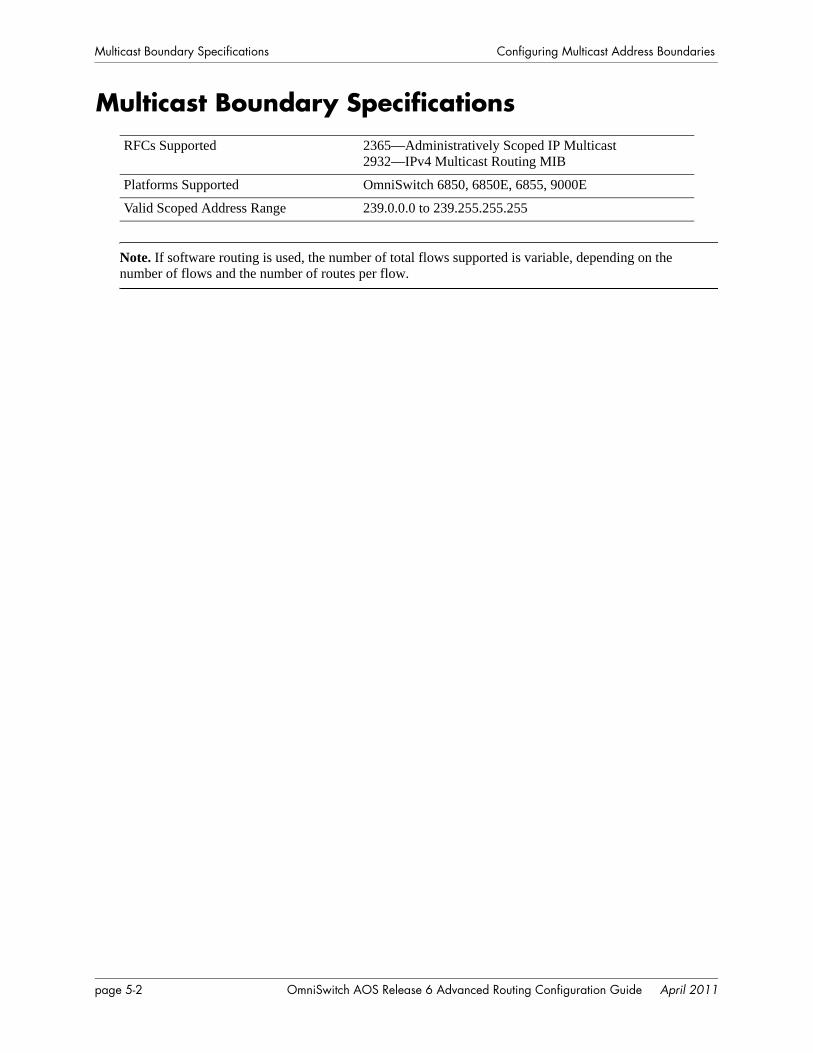
Multicast Boundary Specifications Configuring Multicast Address Boundaries
Multicast Boundary Specifications
Note. If software routing is used, the number of total flows supported is variable, depending on the number of flows and the number of routes per flow.
RFCs Supported 2365—Administratively Scoped IP Multicast2932—IPv4 Multicast Routing MIB
Platforms Supported OmniSwitch 6850, 6850E, 6855, 9000E
Valid Scoped Address Range 239.0.0.0 to 239.255.255.255
page 5-2 OmniSwitch AOS Release 6 Advanced Routing Configuration Guide April 2011
Configuring Multicast Address Boundaries Quick Steps for Configuring Multicast Address Boundaries
Quick Steps for Configuring Multicast Address BoundariesUsing Existing IP Interfaces
1 Before attempting to configure a multicast address boundary, be sure that you have manually loaded the multicast protocol software for your network (e.g., PIM-SM or DVMRP). Otherwise, you will receive an error stating that “the specified application is not loaded.” To manually load multicast protocol soft-ware, use the ip load command. For example:
-> ip load pim
2 Configure a multicast address boundary for a VLAN interface using the ip mroute-boundary command. Information must include the interface IP address, followed by the multicast boundary address and the corresponding subnet mask. For example:
-> ip mroute-boundary vlan-3 239.120.0.0 255.255.0.0
On New IP Interface
1 Be sure that you have loaded one of the dynamic routing features (e.g., PIM-SM). Otherwise, you will receive an error stating that “the specified application is not loaded.” To load a dynamic routing feature, use the ip load command. For example:
-> ip load pim
2 Create a new IP interface on an existing VLAN by specifying a valid IP address. For example:
-> ip interface vlan-2 address 178.14.1.43 vlan 3
The VLAN must already be created on the switch. For information about creating VLANs, see the “Configuring VLANs” chapter in the OmniSwitch AOS Release 6 Network Configuration Guide.
3 Configure a multicast address boundary on the IP interface. Information must include the IP address assigned at step 2, as well as a scoped multicast address and the corresponding subnet mask. For example:
-> ip mroute-boundary vlan-2 239.120.0.0 255.255.0.0
Note. Optional. To verify the multicast boundary configuration, enter the show ip mroute-boundary command. The display is similar to the one shown here:
-> show ip mroute-boundaryInterface Name Interface Address Boundary Address--------------+-----------------+-------------------vlan-2 178.14.1.43 239.120.0.0/16
For more information about this display, see the “Multicast Routing Commands” chapter in the OmniSwitch CLI Reference Guide.
OmniSwitch AOS Release 6 Advanced Routing Configuration Guide April 2011 page 5-3
Multicast Address Boundaries Overview Configuring Multicast Address Boundaries
Multicast Address Boundaries Overview
Multicast Addresses and the IANA
The Internet Assigned Numbers Authority (IANA) regulates unique parameters for different types of network protocols. For example, the IANA regulates addresses for IP, DVMRP, PIM, PIM-SSM, etc., and also provides a range of administratively scoped multicast addresses. For more information, refer to the section below.
Administratively Scoped Multicast AddressesMulticast addresses 239.0.0.0 through 239.255.255.255 have been reserved by the IANA as administra-tively scoped addresses for use in private multicast domains. These addresses cannot be used for any other protocol or network function. Because they are regulated by the IANA, these addresses can theoretically be used by network administrators without conflicting with networks outside of their multicast domains. However, to ensure that the addresses used in a private multicast domain do not conflict with other domains (e.g., within the company network or out on the Internet), multicast address boundaries must be configured.
Source-Specific Multicast AddressesMulticast addresses 232.0.0.0 through 232.255.255.255 have been reserved by the Internet Assigned Numbers Authority (IANA) as source-specific multicast (SSM) destination addresses. Addresses within this range are reserved for use by source-specific applications and protocols (e.g., PIM-SSM) and cannot be used for any other functions or protocols.
page 5-4 OmniSwitch AOS Release 6 Advanced Routing Configuration Guide April 2011
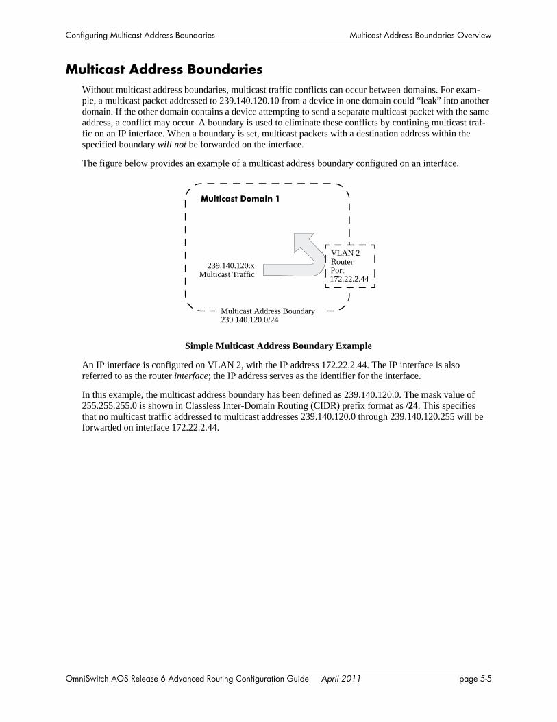
Configuring Multicast Address Boundaries Multicast Address Boundaries Overview
Multicast Address BoundariesWithout multicast address boundaries, multicast traffic conflicts can occur between domains. For exam-ple, a multicast packet addressed to 239.140.120.10 from a device in one domain could “leak” into another domain. If the other domain contains a device attempting to send a separate multicast packet with the same address, a conflict may occur. A boundary is used to eliminate these conflicts by confining multicast traf-fic on an IP interface. When a boundary is set, multicast packets with a destination address within the specified boundary will not be forwarded on the interface.
The figure below provides an example of a multicast address boundary configured on an interface.
Simple Multicast Address Boundary Example
An IP interface is configured on VLAN 2, with the IP address 172.22.2.44. The IP interface is also referred to as the router interface; the IP address serves as the identifier for the interface.
In this example, the multicast address boundary has been defined as 239.140.120.0. The mask value of 255.255.255.0 is shown in Classless Inter-Domain Routing (CIDR) prefix format as /24. This specifies that no multicast traffic addressed to multicast addresses 239.140.120.0 through 239.140.120.255 will be forwarded on interface 172.22.2.44.
Multicast Domain 1
Multicast Address Boundary 239.140.120.0/24
239.140.120.xMulticast Traffic
VLAN 2Router Port172.22.2.44
OmniSwitch AOS Release 6 Advanced Routing Configuration Guide April 2011 page 5-5
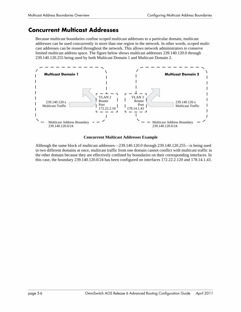
Multicast Address Boundaries Overview Configuring Multicast Address Boundaries
Concurrent Multicast AddressesBecause multicast boundaries confine scoped multicast addresses to a particular domain, multicast addresses can be used concurrently in more than one region in the network. In other words, scoped multi-cast addresses can be reused throughout the network. This allows network administrators to conserve limited multicast address space. The figure below shows multicast addresses 239.140.120.0 through 239.140.120.255 being used by both Multicast Domain 1 and Multicast Domain 2.
Concurrent Multicast Addresses Example
Although the same block of multicast addresses—239.140.120.0 through 239.140.120.255—is being used in two different domains at once, multicast traffic from one domain cannot conflict with multicast traffic in the other domain because they are effectively confined by boundaries on their corresponding interfaces. In this case, the boundary 239.140.120.0/24 has been configured on interfaces 172.22.2.120 and 178.14.1.43.
Multicast Domain 1 Multicast Domain 2
Multicast Address Boundary 239.140.120.0/24
Multicast Address Boundary 239.140.120.0/24
VLAN 2Router Port172.22.2.10
VLAN 3Router
Port178.14.1.43
239.140.120.xMulticast Traffic
239.140.120.xMulticast Traffic
page 5-6 OmniSwitch AOS Release 6 Advanced Routing Configuration Guide April 2011
Configuring Multicast Address Boundaries Configuring Multicast Address Boundaries
Configuring Multicast Address BoundariesBecause multicast address boundaries are part of the Advanced Routing software, the advanced routing image must be present in an OmniSwitch, before you can begin configuring the feature. In addition, the multicast routing protocol (e.g., PIM-SM or DVMRP) for your network must first be loaded to memory via the ip load command.
Basic Multicast Address Boundary ConfigurationConfiguring a multicast address boundary prevents multicast traffic that is addressed to a particular address or range of addresses from being forwarded on an interface. Boundaries may be configured in more than one region in the network.
The basic command for creating a multicast address boundary is:
ip mroute-boundary
The next section describes how to use this command.
Creating a Multicast Address BoundaryTo create a multicast address boundary on an interface, enter the ip mroute-boundary command, with the interface IP address, the boundary address, and the corresponding mask. For example:
-> ip mroute-boundary vlan-2 239.120.0.0 255.255.0.0
The interface IP address must be a valid IP interface that has been assigned to an existing VLAN. For information about creating VLANs and assigning IP interfaces, see the “Configuring VLANs” chapter in the OmniSwitch AOS Release 6 Network Configuration Guide.
The boundary address must be an administratively-scoped multicast address from 239.0.0.0 to 239.255.255.255.
Deleting a Multicast Address BoundaryTo delete a multicast address boundary from an interface, enter the no ip mroute-boundary command, with the interface IP address, the boundary address, and the corresponding mask. For example:
-> no ip mroute-boundary vlan-2 239.120.0.0 255.255.0.0
OmniSwitch AOS Release 6 Advanced Routing Configuration Guide April 2011 page 5-7
Verifying the Multicast Address Boundary Configuration Configuring Multicast Address Boundaries
Verifying the Multicast Address Boundary Configuration
A summary of the show commands used for verifying the multicast address boundary configuration is given here:
For more information about the displays that result from these commands, see the OmniSwitch CLI Refer-ence Guide.
Application Example for Configuring Multicast Address Boundaries
This section illustrates multicast address boundary configuration for a simple multicast network. The network consists of a core switch with a backbone connection to the Internet. The core switch is given a boundary of 239.0.0.0/8. This is the broadest boundary, keeping all multicast traffic addressed to 239.0.0.0 through 239.255.255.255 from leaving the company network.
The core switch is connected to two wiring closet switches. The wiring closet switches serve the Human Resources and Training network domains. A boundary of 239.188.0.0/16 is created for both the Human Resources and Training domains. No multicast traffic within the range of 239.188.0.0 through 239.188.255.255 is permitted to leave either domain. This allows multicast addresses within the range to be used simultaneously in both domains without conflict.
Note. For a diagram showing this sample network with the multicast address boundaries described above, refer to page 5-11.
1 Verify that either PIM or DVMRP is loaded on the switch. Refer to the “Configuring PIM” or “Config-uring DVMRP” chapters in the OmniSwitch AOS Release 6 Advanced Routing Configuration Guide for more information.
2 Create a VLAN on the core switch. For example:
-> vlan 2
3 Next, create a IP interface on the VLAN. The IP interface serves as the interface identifier on which the boundary will be created. To create a IP interface, use the ip interface command. For example:
-> ip interface vlan-2 address 178.10.1.1 vlan 2
show ip mroute-boundary Displays scoped multicast address boundaries for the switch’s router interfaces.
page 5-8 OmniSwitch AOS Release 6 Advanced Routing Configuration Guide April 2011
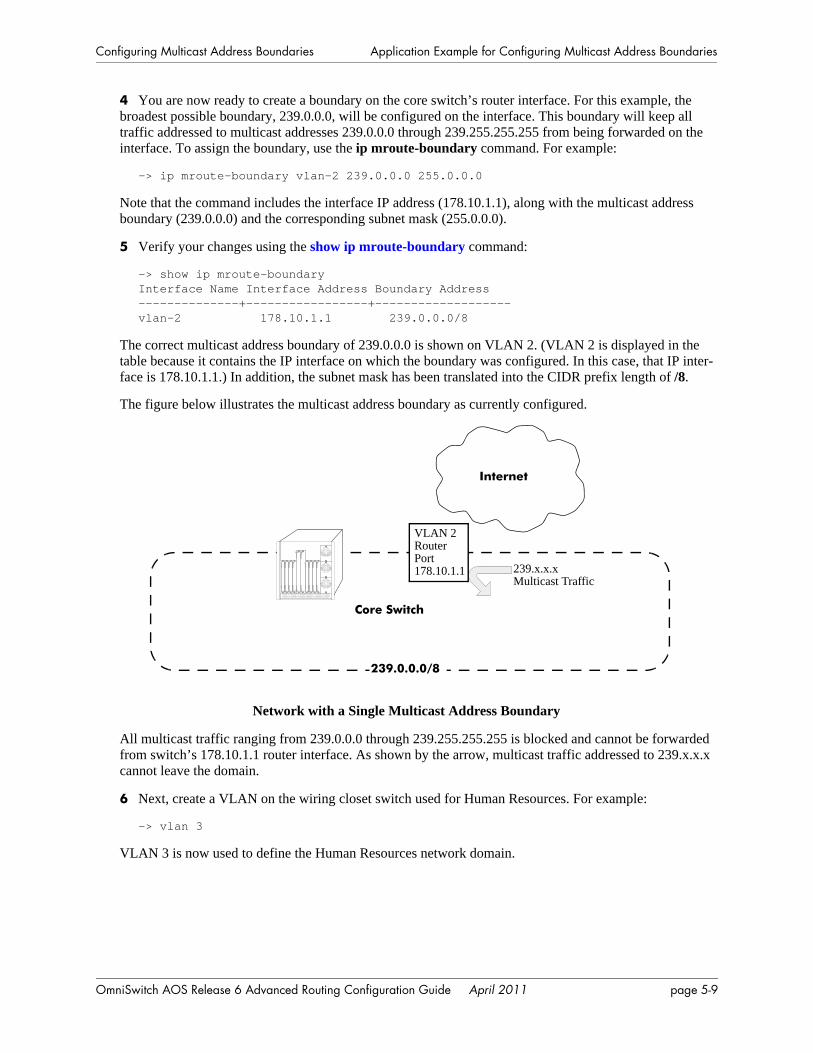
Configuring Multicast Address Boundaries Application Example for Configuring Multicast Address Boundaries
4 You are now ready to create a boundary on the core switch’s router interface. For this example, the broadest possible boundary, 239.0.0.0, will be configured on the interface. This boundary will keep all traffic addressed to multicast addresses 239.0.0.0 through 239.255.255.255 from being forwarded on the interface. To assign the boundary, use the ip mroute-boundary command. For example:
-> ip mroute-boundary vlan-2 239.0.0.0 255.0.0.0
Note that the command includes the interface IP address (178.10.1.1), along with the multicast address boundary (239.0.0.0) and the corresponding subnet mask (255.0.0.0).
5 Verify your changes using the show ip mroute-boundary command:
-> show ip mroute-boundaryInterface Name Interface Address Boundary Address--------------+-----------------+-------------------vlan-2 178.10.1.1 239.0.0.0/8
The correct multicast address boundary of 239.0.0.0 is shown on VLAN 2. (VLAN 2 is displayed in the table because it contains the IP interface on which the boundary was configured. In this case, that IP inter-face is 178.10.1.1.) In addition, the subnet mask has been translated into the CIDR prefix length of /8.
The figure below illustrates the multicast address boundary as currently configured.
Network with a Single Multicast Address Boundary
All multicast traffic ranging from 239.0.0.0 through 239.255.255.255 is blocked and cannot be forwarded from switch’s 178.10.1.1 router interface. As shown by the arrow, multicast traffic addressed to 239.x.x.x cannot leave the domain.
6 Next, create a VLAN on the wiring closet switch used for Human Resources. For example:
-> vlan 3
VLAN 3 is now used to define the Human Resources network domain.
VLAN 2Router Port178.10.1.1
Internet
Core Switch
239.x.x.xMulticast Traffic
239.0.0.0/8
OmniSwitch AOS Release 6 Advanced Routing Configuration Guide April 2011 page 5-9
Application Example for Configuring Multicast Address Boundaries Configuring Multicast Address Boundaries
7 Create an IP interface on VLAN 3. For example:
-> ip interface vlan-3 address 178.20.1.1 vlan 3
8 Assign a boundary on the switch’s router interface. For this example, the interface is given the bound-ary 239.188.0.0/16. This boundary will keep all traffic addressed to multicast addresses 239.188.0.0 through 239.188.255.255 from being forwarded on the interface:
-> ip mroute-boundary vlan-3 239.188.0.0 255.255.0.0
The command syntax includes the interface IP address (178.20.1.1), along with the multicast address boundary (239.188.0.0) and the corresponding subnet mask (255.255.0.0).
9 Create a VLAN on the separate wiring closet switch used for Training. For example:
-> vlan 4
VLAN 4 is now used to define the Training network domain.
10 Create an IP interface on VLAN 4. For example:
-> ip interface vlan-4 address 178.30.1.1 vlan 4
11 Assign a boundary on the Training router interface. The interface is given the same boundary as Human Resources (i.e., 239.188.0.0/16).
-> ip mroute-boundary vlan-4 239.188.0.0 255.255.0.0
Because there is a boundary configured at each domain, multicast users in Human Resources can forward 239.188.x.x multicast traffic without conflicting with users in Training who are forwarding traffic with the same addresses. By allowing addresses to be used concurrently in more than one department, network administrators can conserve limited scoped multicast address space.
page 5-10 OmniSwitch AOS Release 6 Advanced Routing Configuration Guide April 2011
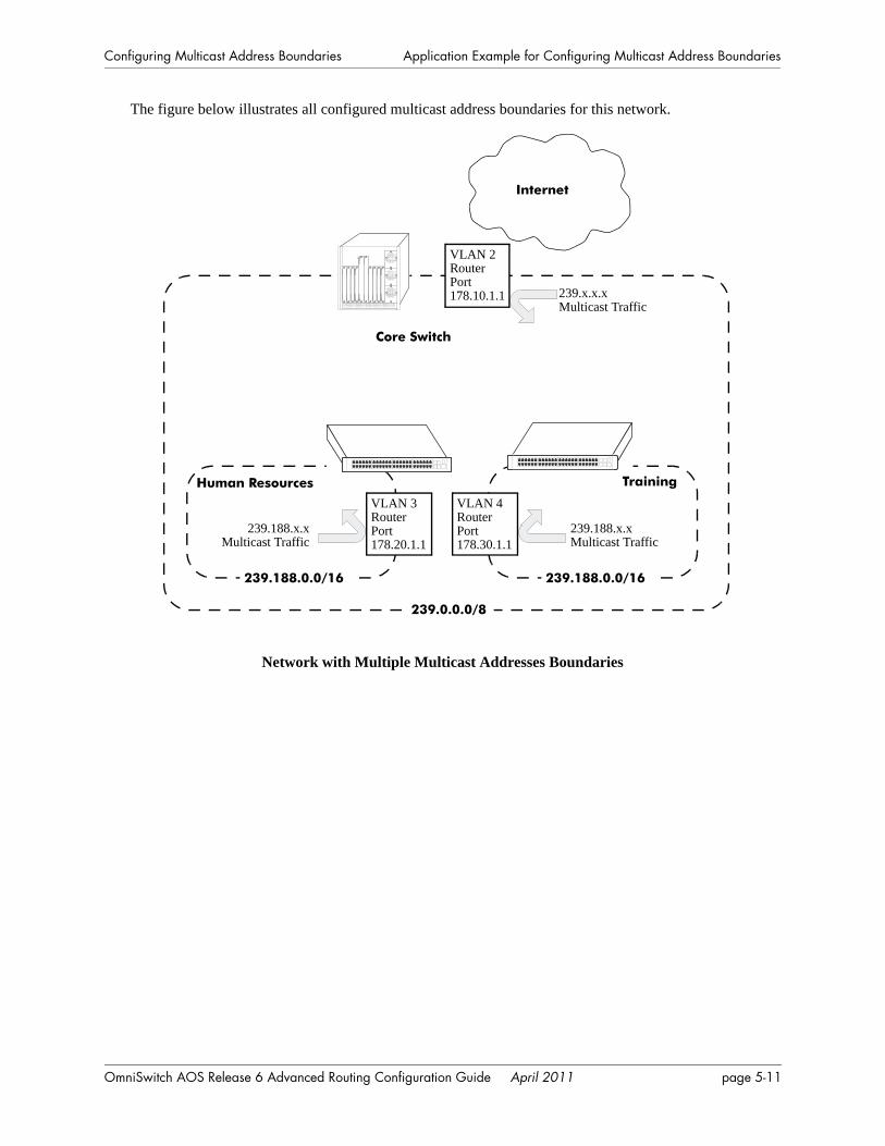
Configuring Multicast Address Boundaries Application Example for Configuring Multicast Address Boundaries
The figure below illustrates all configured multicast address boundaries for this network.
Network with Multiple Multicast Addresses Boundaries
Internet
VLAN 2Router Port178.10.1.1 239.x.x.x
Multicast Traffic
239.0.0.0/8
VLAN 4Router Port178.30.1.1
Core Switch
239.188.x.xMulticast Traffic
239.188.x.xMulticast Traffic
Human Resources Training
239.188.0.0/16 239.188.0.0/16
VLAN 3Router Port178.20.1.1
OmniSwitch AOS Release 6 Advanced Routing Configuration Guide April 2011 page 5-11

Application Example for Configuring Multicast Address Boundaries Configuring Multicast Address Boundaries
page 5-12 OmniSwitch AOS Release 6 Advanced Routing Configuration Guide April 2011
6 Configuring DVMRP
This chapter includes descriptions for Distance Vector Multicast Routing Protocol (DVMRP). DVMRP is a dense-mode multicast routing protocol. DVMRP—which is essentially a “broadcast and prune” routing protocol—is designed to assist routers in propagating IP multicast traffic through a network.
In This ChapterThis chapter describes the basic components of DVMRP and how to configure them through the Command Line Interface (CLI). CLI commands are used in the configuration examples; for more details about the syntax of commands, see the OmniSwitch CLI Reference Guide.
Configuration procedures described in this chapter include:
• Loading DVMRP into memory—see page 6-9.
• Enabling DVMRP—see page 6-11.
• Neighbor communications—see page 6-12.
• Routes—see page 6-13.
• Pruning—see page 6-14.
• Grafting—see page 6-16.
• Tunnels—see page 6-16.
• Verifying the DVMRP configuration—see page 6-17.
OmniSwitch AOS Release 6 Advanced Routing Configuration Guide April 2011 page 6-1
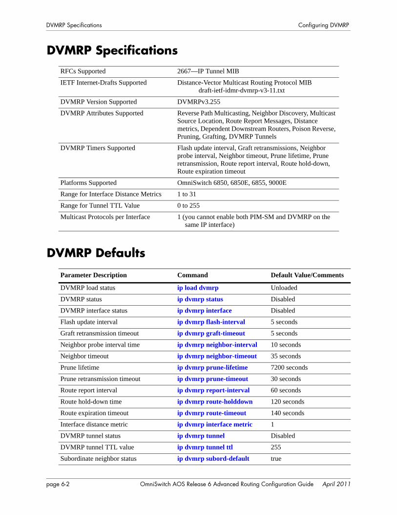
DVMRP Specifications Configuring DVMRP
DVMRP Specifications
DVMRP Defaults
RFCs Supported 2667—IP Tunnel MIB
IETF Internet-Drafts Supported Distance-Vector Multicast Routing Protocol MIB draft-ietf-idmr-dvmrp-v3-11.txt
DVMRP Version Supported DVMRPv3.255
DVMRP Attributes Supported Reverse Path Multicasting, Neighbor Discovery, Multicast Source Location, Route Report Messages, Distance metrics, Dependent Downstream Routers, Poison Reverse, Pruning, Grafting, DVMRP Tunnels
DVMRP Timers Supported Flash update interval, Graft retransmissions, Neighbor probe interval, Neighbor timeout, Prune lifetime, Prune retransmission, Route report interval, Route hold-down, Route expiration timeout
Platforms Supported OmniSwitch 6850, 6850E, 6855, 9000E
Range for Interface Distance Metrics 1 to 31
Range for Tunnel TTL Value 0 to 255
Multicast Protocols per Interface 1 (you cannot enable both PIM-SM and DVMRP on the same IP interface)
Parameter Description Command Default Value/Comments
DVMRP load status ip load dvmrp Unloaded
DVMRP status ip dvmrp status Disabled
DVMRP interface status ip dvmrp interface Disabled
Flash update interval ip dvmrp flash-interval 5 seconds
Graft retransmission timeout ip dvmrp graft-timeout 5 seconds
Neighbor probe interval time ip dvmrp neighbor-interval 10 seconds
Neighbor timeout ip dvmrp neighbor-timeout 35 seconds
Prune lifetime ip dvmrp prune-lifetime 7200 seconds
Prune retransmission timeout ip dvmrp prune-timeout 30 seconds
Route report interval ip dvmrp report-interval 60 seconds
Route hold-down time ip dvmrp route-holddown 120 seconds
Route expiration timeout ip dvmrp route-timeout 140 seconds
Interface distance metric ip dvmrp interface metric 1
DVMRP tunnel status ip dvmrp tunnel Disabled
DVMRP tunnel TTL value ip dvmrp tunnel ttl 255
Subordinate neighbor status ip dvmrp subord-default true
page 6-2 OmniSwitch AOS Release 6 Advanced Routing Configuration Guide April 2011
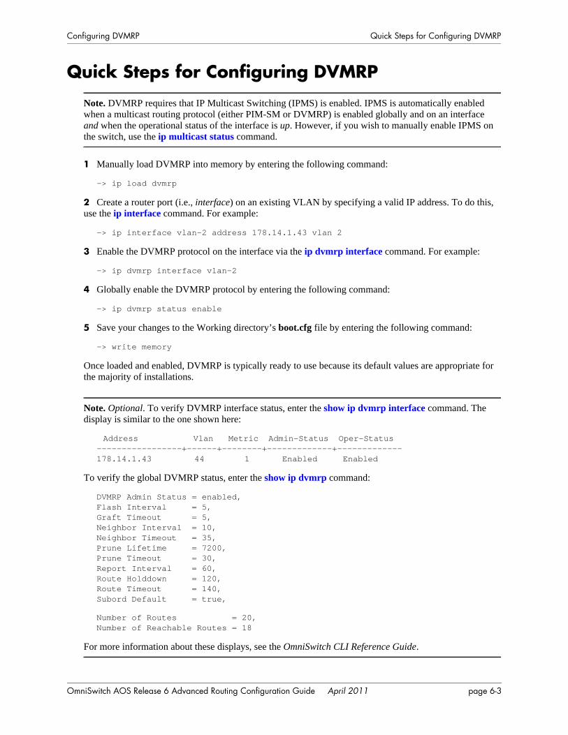
Configuring DVMRP Quick Steps for Configuring DVMRP
Quick Steps for Configuring DVMRP
Note. DVMRP requires that IP Multicast Switching (IPMS) is enabled. IPMS is automatically enabled when a multicast routing protocol (either PIM-SM or DVMRP) is enabled globally and on an interface and when the operational status of the interface is up. However, if you wish to manually enable IPMS on the switch, use the ip multicast status command.
1 Manually load DVMRP into memory by entering the following command:
-> ip load dvmrp
2 Create a router port (i.e., interface) on an existing VLAN by specifying a valid IP address. To do this, use the ip interface command. For example:
-> ip interface vlan-2 address 178.14.1.43 vlan 2
3 Enable the DVMRP protocol on the interface via the ip dvmrp interface command. For example:
-> ip dvmrp interface vlan-2
4 Globally enable the DVMRP protocol by entering the following command:
-> ip dvmrp status enable
5 Save your changes to the Working directory’s boot.cfg file by entering the following command:
-> write memory
Once loaded and enabled, DVMRP is typically ready to use because its default values are appropriate for the majority of installations.
Note. Optional. To verify DVMRP interface status, enter the show ip dvmrp interface command. The display is similar to the one shown here:
Address Vlan Metric Admin-Status Oper-Status-----------------+------+--------+-------------+-------------178.14.1.43 44 1 Enabled Enabled
To verify the global DVMRP status, enter the show ip dvmrp command:
DVMRP Admin Status = enabled,Flash Interval = 5,Graft Timeout = 5,Neighbor Interval = 10,Neighbor Timeout = 35,Prune Lifetime = 7200,Prune Timeout = 30,Report Interval = 60,Route Holddown = 120,Route Timeout = 140,Subord Default = true,
Number of Routes = 20,Number of Reachable Routes = 18
For more information about these displays, see the OmniSwitch CLI Reference Guide.
OmniSwitch AOS Release 6 Advanced Routing Configuration Guide April 2011 page 6-3
DVMRP Overview Configuring DVMRP
DVMRP OverviewDistance Vector Multicast Routing Protocol (DVMRP) Version 3 is a multicast routing protocol that enables routers to efficiently propagate IP multicast traffic through a network. Multicast traffic consists of a data stream that originates from a single source and is sent to hosts that have subscribed to that stream. Live video broadcasts, video conferencing, corporate communications, distance learning, and distribution of software, stock quotes, and news services are examples of multicast traffic. Multicast traffic is distin-guished from unicast traffic and broadcast traffic as follows:
• Unicast traffic is addressed to a single host.
• Broadcast traffic is transmitted to all hosts.
• Multicast traffic is transmitted to a subset of hosts (the hosts that have subscribed to the multicast data stream).
DVMRP is a distributed multicast routing protocol that dynamically generates per-source delivery trees based upon routing exchanges, using a technique called Reverse Path Multicasting. When a multicast source begins to transmit, the multicast data is flooded down the delivery tree to all points in the network. DVMRP then prunes (i.e., removes branches from) the delivery tree where the traffic is unwanted.
Pruning continues to occur as group membership changes or routers determine that no group members are present. This restricts the delivery trees to the minimum branches necessary to reach all group members, thus optimizing router performance. New branches can also be added to the delivery trees dynamically as new members join the multicast group. The addition of new branches is referred to as grafting.
Reverse Path MulticastingDVMRP uses Internet Group Management Protocol (IGMP) messages to exchange the routing informa-tion needed to build per-source multicast delivery trees. Once built, packets follow a multicast delivery tree from the source to all members of the multicast group. Packets are replicated only at necessary branches in the delivery tree. The trees are calculated and updated dynamically to track the membership of individual groups.
When a packet arrives on an interface, the reverse path back to the source of the packet is determined by examining a DVMRP routing table of known source networks. If the packet arrived on an upstream inter-face that would be used to transmit packets back to the source, it is forwarded to the appropriate list of downstream interfaces. Otherwise, it is not on the optimal delivery tree and is discarded. In this way dupli-cate packets can be filtered when loops exist in the network topology.
page 6-4 OmniSwitch AOS Release 6 Advanced Routing Configuration Guide April 2011
Configuring DVMRP DVMRP Overview
Neighbor DiscoveryDVMRP routers must maintain a database of DVMRP adjacencies with other DVMRP routers. A DVMRP router must be aware of its DVMRP neighbors on each interface. To gather this information, DVMRP routers use a neighbor discovery mechanism and periodically multicast DVMRP Probe messages to the All-DVMRP-Routers group address (224.0.0.4). Each Probe message includes a Neighbor List of DVMRP routers known to the transmitting router.
When a DVMRP router (let’s call it “router B”) receives a Probe (let’s say from “router A”), it adds the IP address of router A to its own internal list of DVMRP neighbors on that interface. It then sends a Probe of its own with the IP address of router A included in the Probe’s Neighbor List. When a DVMRP router receives a Probe with its own IP address included in the Neighbor List, the router knows that a two-way adjacency has been successfully formed between itself and the neighbor that sent the Probe.
Probes effectively serve three main purposes:
• Probes provide a mechanism for DVMRP routers to locate each other as described above.
• Probes provide a way for DVMRP routers to determine each others’ capabilities. This is deduced from the major and minor version numbers in the Probe packet and directly from the capability flags in the Probe packet.
• Probes provide a keep-alive function in order to quickly detect neighbor loss.
A DVMRP router sends periodic Route Report messages to its DVMRP neighbors (by default, every 60 seconds). A Route Report message contains the sender’s current routing table, which contains entries that advertise a source network (with a mask) and a hop-count that is used as the routing metric.This routing information is used to build source distribution trees and to perform multicast forwarding. The DVMRP neighbor that advertises the route with the lowest metric will be used for forwarding. (In case of a tie, the DVMRP neighbor with the lowest IP address will be used.)
In DVMRPv3, a router will not accept a Route Report from another DVMRP router until it has estab-lished adjacency with that neighboring router.
Note. Older versions of DVMRP use Route Report messages to perform neighbor discovery rather than the Probe messages used in DVMRP Version 3.
OmniSwitch AOS Release 6 Advanced Routing Configuration Guide April 2011 page 6-5
DVMRP Overview Configuring DVMRP
Multicast Source Location, Route Report Messages, and MetricsWhen an IP multicast packet is received by a router running DVMRP, it first looks up the source network in the DVMRP routing table. The interface that provides the best route back to the source of the packet is called the upstream interface. If the packet arrived on that upstream interface, then it is a candidate for forwarding to one or more downstream interfaces. If the packet did not arrive on that anticipated upstream interface, then it is discarded. This check is known as a reverse path forwarding check and is performed by all DVMRP routers.
Note. Under normal, stable DVMRP operation, packets would not arrive on the wrong interface because the upstream router would not forward the packet unless the downstream router poison-reversed the route in the first place (as explained below). However, there are cases—such as immediately after a network topology change—when DVMRP routing has not yet converged across all routers where this can occur. It can also occur when loops exist in the network topology.
In order to ensure that all DVMRP routers have a consistent view of the path back to a source, routing tables are propagated by all DVMRP routers in Route Report messages. Each router transmits a Route Report message at specified intervals. The Route Report message advertises the network numbers and masks of those interfaces to which the router is directly connected. It also relays the routes received from neighboring routers.
DVMRP requires an interface metric (i.e., a hop count) to be configured on all physical and tunnel inter-faces. When a route is received from a neighboring router via a Route Report message, the metric of the interface over which the packet was received is added to the metric of the route being advertised. This adjusted metric is used when comparing metrics to determine the most efficient upstream interface.
Dependent Downstream Routers and Poison ReverseIn addition to providing a consistent view of source networks, the exchange of routes in DVMRP Route Report messages provides one other important feature. DVMRP uses the route exchange as a mechanism for upstream routers to determine if any downstream routers depend on them for forwarding packets from particular source networks.
DVMRP accomplishes this by using a technique called poison reverse. If a downstream router selects an upstream router as the best next hop to a particular source network, it indicates this by echoing back the route on the upstream interface with a metric equal to the original metric plus infinity. (DVMRP uses a metric of 32 as infinity.) When the upstream router receives the report and sees a metric that lies between infinity and twice infinity (that is, between 32 and 64), it adds the downstream router from which it received the report to a list of dependent routers for this source network.
The list of dependent routers per source network built by the poison reverse technique provides the foun-dation necessary to determine when it is appropriate to prune back the IP source-specific multicast trees.
Note. Poison reverse is used differently in DVMRP than in most unicast distance vector routing protocols (such as RIP), which use poison reverse to advertise that a particular route is unreachable.
page 6-6 OmniSwitch AOS Release 6 Advanced Routing Configuration Guide April 2011
Configuring DVMRP DVMRP Overview
Pruning Multicast Traffic DeliveryInitially, all interfaces with downstream-dependent neighbors are included in the downstream interface list and multicast traffic is flooded down the truncated broadcast tree to all possible receivers. This allows the downstream routers to be aware of traffic destined for a particular Source, Group (S, G) pair. The down-stream routers then have the option to send prunes (and subsequent grafts) for this (S, G) pair as require-ments change.
A DVMRP router will remove an interface from its forwarding list that has no group members associated with an IP multicast packet. If a router removes all of its downstream interfaces, it notifies the upstream router that it no longer wants traffic destined for that particular (S, G) pair. This is accomplished by send-ing a DVMRP Prune message upstream to the router expected to forward packets from that particular source.
A downstream router will inform an upstream router that it depends on the upstream router to receive packets from particular source networks by using the poison reverse technique during the exchange of Route Report messages. This method allows the upstream router to build a list of downstream routers on each interface that are dependent upon it for packets from a particular source. If the upstream router receives Prune messages from each one of the dependent downstream routers on an interface, then the upstream router can in turn remove this interface from its downstream interface list. If the upstream router is able to remove all of its downstream interfaces in this manner, it can then send a DVMRP Prune message to its upstream router. This continues until all unneeded branches are removed. Refer to “Pruning” on page 6-14 for more specific information on pruning.
Grafting Branches Back onto the Multicast Delivery TreeA pruned branch will be automatically reattached to the multicast delivery tree when the prune times out. However, the graft mechanism provides a quicker method to reattach a pruned branch than waiting for the prune to time out. Without the graft mechanism, the join latency for new hosts in the group might be unac-ceptably great, because the prunes in the upstream routers would have to time out before multicast traffic could again begin to flow to the pruned branches. Depending on the number of routers along the pruned branch and the timeout values in use, several minutes might elapse before the host could begin to receive multicast traffic. By using a graft mechanism, DVMRP reduces the join latency to a few milliseconds.
The graft mechanism is made reliable through the use of Graft-Ack (Graft Acknowledgment) messages. A Graft-Ack message is returned by the upstream router in response to a Graft message. If the Graft-Ack message is not received, the downstream router will resend the Graft message. This prevents the loss of a Graft message due to congestion.
The ip dvmrp graft-timeout command enables you to set the Graft message retransmission value. This value defines the duration of time that the router will wait before retransmitting a Graft message if it has not received a Graft-Ack message. Refer to “Grafting” on page 6-16 for more information.
OmniSwitch AOS Release 6 Advanced Routing Configuration Guide April 2011 page 6-7
DVMRP Overview Configuring DVMRP
DVMRP TunnelsBecause not all IP routers support native multicast routing, DVMRP includes direct support for tunneling IP multicast packets through routers. Tunnel interfaces are used when routers incapable of supporting multicast traffic exist between DVMRP neighbors. In tunnel interfaces, IP multicast packets are encapsu-lated in unicast IP packets and addressed directly to the routers that do not support native multicast rout-ing. DVMRP protocol messages (such as Route Reports, Probes for neighbor discovery, etc.) and multicast traffic are sent between tunnel endpoints using unicast, rather than multicast, packets.
Multicast data is encapsulated using a standard IP-IP encapsulation method. The unicast IP addresses of the tunnel endpoints are used as the source and destination IP addresses in the outer IP header. The inner IP header remains unchanged from the original multicast packet.
page 6-8 OmniSwitch AOS Release 6 Advanced Routing Configuration Guide April 2011
Configuring DVMRP Configuring DVMRP
Configuring DVMRPBefore configuring DVMRP, consider the following:
• The advanced routing image must be present in the switch’s current running directory (i.e., Working or Certified) before DVMRP can be enabled or configured.
• DVMRP requires that IP Multicast Switching (IPMS) is enabled. IPMS is automatically enabled when a multicast routing protocol (either PIM-SM or DVMRP) is enabled globally and on an interface and when the operational status of the interface is up. However, if you wish to manually enable IPMS on the switch, use the ip multicast status command.
• You can configure DVMRP parameters when the protocol is not running as long as DVMRP is loaded into memory (see “Loading DVMRP into Memory” below).
• The DVMRP parameters will not take effect until the protocol is enabled globally and on specific IP interfaces.
Enabling DVMRP on the SwitchBy default, the DVMRP protocol is disabled on the switch. Before running DVMRP, you must enable the protocol by completing the following steps:
• Loading DVMRP into memory
• Enabling DVMRP on desired IP interfaces
• Enabling DVMRP globally on the switch
Note. Once loaded and enabled, DVMRP is typically ready to use because its factory default values are appropriate for the majority of installations. Note, however, if neighbors in the DVMRP domain have difficulty handling large initial bursts of traffic, it is recommended that the subordinate neighbor status is changed to false. For more information on the subordinate neighbor status, refer to the ip dvmrp subord-default command in the OmniSwitch CLI Reference Guide.
For information on completing these steps, refer to the sections below.
Loading DVMRP into MemoryYou must load DVMRP into memory before you can begin configuring the protocol on the switch. If DVMRP is not loaded and you enter a configuration command, the following message displays:
ERROR: The specified application is not loaded
To dynamically load DVMRP into memory, enter the following command:
-> ip load dvmrp
OmniSwitch AOS Release 6 Advanced Routing Configuration Guide April 2011 page 6-9
Configuring DVMRP Configuring DVMRP
Enabling DVMRP on a Specific Interface
Note. It does not matter whether DVMRP is first enabled globally or on specific interfaces. However, DVMRP will not run on an interface until it is enabled both globally and on the interface.
DVMRP must be enabled on an interface before any other interface-specific DVMRP command can be executed (e.g, the ip dvmrp interface metric command). An interface can be any IP router port that has been assigned to an existing VLAN. For information on assigning a router port to a VLAN, refer to the “Configuring VLANs” chapter in the OmniSwitch AOS Release 6 Network Configuration Guide.
To enable DVMRP on a specific interface, use the ip dvmrp interface command. The interface identifier used in the command syntax is the valid IP address of an existing VLAN router port. For example:
-> ip dvmrp interface vlan-2
Note. Only one multicast routing protocol is supported per interface. This means that you cannot enable both PIM-SM and DVMRP on the same interface.
Disabling DVMRP on a Specific Interface
To disable DVMRP on a specific IP interface, use the no ip dvmrp interface command. Be sure to include the interface IP address. For example:
-> no ip dvmrp interface vlan-2
Specifying a Distance Metric on a Specific Interface
The ip dvmrp interface metric command enables you to specify the distance metric for an interface. The default interface distance metric value is 1. DVMRP uses the metric value to determine the most cost-effective way of passing data. The higher an interface’s metric value, the higher the cost of passing data over that interface. DVMRP will transmit data over the interface with the lowest available metric. Note that, just as in RIP, the metric of an incoming route advertisement is automatically incremented by the metric of the incoming interface (typically one hop). You can assign an interface any distance metric from 1 to 31.
To assign a distance metric to a specific interface, use the ip dvmrp interface metric command. The command syntax must include the IP address for the VLAN router port (i.e., interface), as well as a distance metric value. For example:
-> ip dvmrp interface vlan-2
page 6-10 OmniSwitch AOS Release 6 Advanced Routing Configuration Guide April 2011
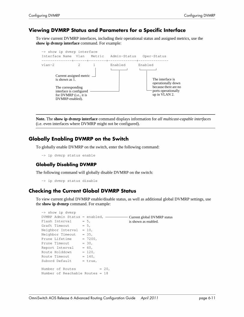
Configuring DVMRP Configuring DVMRP
Viewing DVMRP Status and Parameters for a Specific InterfaceTo view current DVMRP interfaces, including their operational status and assigned metrics, use the show ip dvmrp interface command. For example:
Note. The show ip dvmrp interface command displays information for all multicast-capable interfaces (i.e. even interfaces where DVMRP might not be configured).
Globally Enabling DVMRP on the SwitchTo globally enable DVMRP on the switch, enter the following command:
-> ip dvmrp status enable
Globally Disabling DVMRP
The following command will globally disable DVMRP on the switch:
-> ip dvmrp status disable
Checking the Current Global DVMRP StatusTo view current global DVMRP enable/disable status, as well as additional global DVMRP settings, use the show ip dvmrp command. For example:
-> show ip dvmrp interfaceInterface Name Vlan Metric Admin-Status Oper-Status--------------+------+--------+-------------+--------------vlan-2 2 1 Enabled Enabled
The corresponding interface is configured for DVMRP (i.e., it is DVMRP-enabled).
Current assigned metric is shown as 1. The interface is
operationally down because there are no ports operationally up in VLAN 2.
-> show ip dvmrpDVMRP Admin Status = enabled,Flash Interval = 5,Graft Timeout = 5,Neighbor Interval = 10,Neighbor Timeout = 35,Prune Lifetime = 7200,Prune Timeout = 30,Report Interval = 60,Route Holddown = 120,Route Timeout = 140,Subord Default = true,
Number of Routes = 20,Number of Reachable Routes = 18
Current global DVMRP status is shown as enabled.
OmniSwitch AOS Release 6 Advanced Routing Configuration Guide April 2011 page 6-11
Configuring DVMRP Configuring DVMRP
Automatic Loading and Enabling of DVMRP Following a System BootIf any DVMRP command is saved to the boot.cfg file in the post-boot running directory, DVMRP will be loaded into memory automatically. The post-boot running directory refers to the directory the switch will use as its running directory following the next system boot (i.e., Working or Certified). If the command syntax ip dvmrp status enable is saved to the boot.cfg file in the post-boot running directory, DVMRP will be automatically loaded into memory and globally enabled following the next system boot. For detailed information on the Working and Certified directories and how they are used during system boot, see the “CMM Directory Management” chapter in the OmniSwitch AOS Release 6 Switch Management Guide.
Neighbor CommunicationsProbe messages are sent out periodically on all the DVMRP interfaces. However, only on the non-tunnel interfaces are they sent out to the multicast group address 224.0.0.4.
Note. Older versions of DVMRP use Route Report messages to perform neighbor discovery rather than the Probe messages used in DVMRP Version 3.
The ip dvmrp neighbor-interval command enables you to configure the interval, in seconds, at which Probe messages are transmitted. For example, to configure the Probe interval to ten seconds, enter the following command:
-> ip dvmrp neighbor-interval 10
The ip dvmrp neighbor-timeout command enables you to configure the number of seconds that the DVMRP router will wait for activity from a neighboring DVMRP router before assuming the neighbor is down. For example, to configure the neighbor timeout period to 35 seconds, enter the following command:
-> ip dvmrp neighbor-timeout 35
When the neighbor timeout expires and it is assumed that the neighbor is down, the following occurs:
• All routes learned from the neighbor are immediately placed in hold down.
• If the neighbor is considered to be the designated forwarder for any of the routes it is advertising, a new designated forwarder for each source network is selected.
• If the neighbor is upstream, any cache entries based upon this upstream neighbor are flushed.
• Any outstanding grafts awaiting acknowledgments from this neighbor are flushed.
• All downstream dependencies received from this neighbor are removed.
The ip dvmrp neighbor-interval should be set to 10 seconds and the ip dvmrp neighbor-timeout should be set to 35 seconds. This allows fairly early detection of a lost neighbor yet provides tolerance for busy multicast routers. Both of these values must be coordinated between all DVMRP routers on a physical network segment.
Note. Current global DVMRP parameter values—including the ip dvmrp neighbor-interval value and the ip dvmrp neighbor-timeout value—can be viewed via the show ip dvmrp command. The DVMRP neighbor table can be viewed via the show ip dvmrp neighbor command.
page 6-12 OmniSwitch AOS Release 6 Advanced Routing Configuration Guide April 2011
Configuring DVMRP Configuring DVMRP
RoutesIn DVMRP, source network routing information is exchanged in the same basic manner as it is in RIP. That is to say, periodic Route Report messages are sent between DVMRP neighbors (by default, every 60 seconds). A Route Report contains the sender’s current routing table. The routing table contains entries that advertise a source network (with a mask) and a hop-count that is used as the routing metric. (The key difference between the way routing information is exchanged in DVMRP and in RIP is that DVMRP routes are advertised with a subnet mask, which makes DVMRP effectively a classless protocol.)
The routing information stored in a DVMRP routing table is separate from the unicast routing table and is used to build source distribution trees and to perform multicast forwarding (that is, Reverse Path Forward-ing checks).
The ip dvmrp report-interval command enables you to specify the number of seconds between transmis-sion of Route Report messages. For example, the following command specifies that a Route Report message be sent every 60 seconds:
-> ip dvmrp report-interval 60
The ip dvmrp flash-interval command enables you to specify the number of seconds between transmis-sion of Routing Table Change messages. Routing Table Change messages are sent between transmissions of the complete routing tables contained in Route Report messages. For this reason, the Flash Interval value must be lower than the Route Report interval. For example:
-> ip dvmrp flash-interval 5
The ip dvmrp route-timeout command enables you to specify the route expiration timeout value. The route expiration timeout value determines the number of seconds before a route to an inactive network is aged out. For example, the following command specifies that the route to an inactive network age out in 140 seconds:
-> ip dvmrp route-timeout 140
The ip dvmrp route-holddown command enables you to specify the number of seconds that DVMRP routes are kept in a hold-down state. A hold-down state refers to the period of time that a route to an inac-tive network continues to be advertised as unreachable. When a route is deleted (because it expires, the neighbor it was learned from goes down, etc.) a router may be able to reach the source network described by the route through an alternate gateway. However, in the presence of complex topologies, often the alternate gateway may only be echoing back the same route learned via a different path. If this occurs, the route will continue to be propagated long after it is no longer valid.
In order to prevent this, it is common in distance vector protocols to continue to advertise a route that has been deleted with a metric of infinity for one or more report intervals. This is a hold-down. While it is in hold-down, a route must only be advertised with an infinity metric. The hold down period is usually two report intervals.
For example, the following command specifies that the route to an inactive network continue to be adver-tised for 120 seconds:
-> ip dvmrp route-holddown 120
Note. Current global DVMRP parameter values—including the ip dvmrp report-interval, ip dvmrp flash-interval, ip dvmrp route-timeout, and ip dvmrp route-holddown values—can be viewed via the show ip dvmrp command. The DVMRP routes that are being advertised to other routers can be viewed via the show ip dvmrp route command.
OmniSwitch AOS Release 6 Advanced Routing Configuration Guide April 2011 page 6-13
Configuring DVMRP Configuring DVMRP
PruningDVMRP uses a flood-and-prune mechanism that starts by delivering multicast traffic to all routers in the network. This means that, initially, traffic is flooded down a multicast delivery tree. DVMRP routers then prune this flow where the traffic is unwanted. Routers that have no use for the traffic send DVMRP Prune messages up the delivery tree to stop the flow of unwanted multicast traffic, thus pruning the unwanted branches of the tree. After pruning, a source distribution tree for that specific source exists.
However, the source distribution tree that results from DVMRP pruning reverts back to the original deliv-ery tree when the prunes time out. When a prune times out, traffic is again flooded down the branch.
The ip dvmrp prune-lifetime command sets the period of time that a prune will be in effect — essen-tially, the prune’s lifetime. When the prune-lifetime period expires, the interface is joined back onto the multicast delivery tree. (If unwanted multicast traffic continues to arrive at the interface, the prune mecha-nism is reinitiated and the cycle continues.) For example, the following command sets a prune’s lifetime to 7200 seconds:
-> ip dvmrp prune-lifetime 7200
Refer to “More About Prunes” below for further information on the ip dvmrp prune-lifetime command and how it affects the lifetime of prunes sent and, in some cases, received.
The ip dvmrp prune-timeout command sets the Prune packet retransmission interval. This is the dura-tion of time that the router will wait before retransmitting a Prune message if it continues to receive unwanted multicast traffic. For example, the following command sets the Prune packet retransmission interval to forty seconds:
-> ip dvmrp prune-timeout 40
Note. Current global DVMRP parameter values—including the ip dvmrp prune-lifetime value and the ip dvmrp prune-timeout value—can be viewed via the show ip dvmrp command. Current DVMRP prunes can be viewed via the show ip dvmrp prune command.
More About Prunes
Prune-Lifetime Values in Sent Prune Packets
The value of ip dvmrp prune-lifetime is set to 7200 seconds (two hours) by default. On leaf routers (that is, routers that have no further downstream dependent routers), the value of ip dvmrp prune-lifetime is inserted into prune packets sent upstream as their lifetime value.
However, when a branch router (that is, a router that does have further downstream dependent routers) sends a prune upstream, the prune-lifetime value inserted into the prune packet is the smallest of the following values:
• the value of ip dvmrp prune-lifetime on the sending device
• the amount of lifetime that remains for each individual prune on the router’s timer queue that was received for the pruned group. (When a prune is queued on the router’s timer queue, its lifetime value decrements until the prune expires.)
page 6-14 OmniSwitch AOS Release 6 Advanced Routing Configuration Guide April 2011
Configuring DVMRP Configuring DVMRP
As an example, let’s say that the following situation exists on a branch router: ip dvmrp prune-lifetime is set to 7200 seconds and three prunes for the pruned group exist on the router’s timer queue. These three prunes have remaining lifetimes of 7000 seconds, 5000 seconds, and 4500 seconds. When the branch router sends a prune upstream for this group, a prune-lifetime value of 4500 seconds will be inserted into the prune packet.
Prune-Lifetime Expiration Value
You can view the prunes that have been sent via the show ip dvmrp prune command. (However, note that this command does not display received prunes.) The expiration time displayed by the show ip dvmrp prune command is the earliest time that the router expects multicast traffic for the pruned group to start arriving. If the expiration time displays as expired, the prune has expired but no further multicast traffic has been received. The expiration value may be reset if multicast traffic is received and another prune was sent because no stations downstream want the traffic.
Received Prunes
When prune packets are received, a timer is set up on the receiving device that halts traffic sent to the pruned group on the neighbor that originated the prune. The timer value used is the prune-lifetime value found in the received prune packet. The setting of ip dvmrp prune-lifetime on the device that received the prune is not normally taken into consideration in this situation.
However, there are times when the setting of ip dvmrp prune-lifetime can affect the timeout value used for received prunes. This occurs if the setting of ip dvmrp prune-lifetime is modified after prunes have been received. If the new prune-lifetime value is less than the period of time a received prune has been on the router's timer queue, the router will treat the prune as if it just expired. This means that multicast traf-fic may flow to the neighbor even though the neighbor does not expect the prune to have expired.
Even in cases where modification of the ip dvmrp prune-lifetime setting does not cause the received prunes to expire earlier than specified by their internal prune-lifetime value, such modification will still cause the prune-lifetime value of received prunes to be adjusted to the new value. This means that received prunes may expire sooner or later than the neighbor expects.
Once the lifetime value of received prunes on the router’s timer queue have been modified per the new setting of ip dvmrp prune-lifetime, all future incoming prunes will experience normal timer operation and the prune-lifetime value in the received prune packet will be used without modification. Outgoing prunes will use the new value of ip dvmrp prune-lifetime.
For the reasons explained, the value of ip dvmrp prune-lifetime should only be modified with caution.
OmniSwitch AOS Release 6 Advanced Routing Configuration Guide April 2011 page 6-15
Configuring DVMRP Configuring DVMRP
GraftingA pruned branch will be automatically reattached to the multicast delivery tree when the prune times out. However, the graft mechanism provides a quicker method to reattach a pruned branch than waiting for the prune to time out. As traffic is forwarded, routers that do not want multicast traffic send Prune messages to signal the upstream router to stop sending the traffic. If new IGMP membership requests are later received by the downstream router, the router can send Graft messages to the upstream router and wait for acknowl-edgment (a Graft Ack).
The ip dvmrp graft-timeout command enables you to set the Graft message retransmission value. This value defines the duration of time that the router will wait before retransmitting a Graft message if it has not received a Graft-Ack message acknowledging that a previously transmitted Graft message was received. For example, enter the following to set the Graft message retransmission value to 5 seconds:
-> ip dvmrp graft-timeout 5
Note. Current global DVMRP parameter values, including the ip dvmrp graft-timeout value, can be viewed via the show ip dvmrp command.
TunnelsDVMRP networks may use DVMRP tunnels to interconnect two multicast-enabled networks across non-multicast networks. In a DVMRP tunnel, IP multicast packets are encapsulated in unicast IP packets so that the multicast traffic can traverse a non-multicast network.
The ip dvmrp tunnel command enables you to add or delete a DVMRP tunnel between a specified local interface name and remote address. Any packets sent through the tunnel will be encapsulated in an outer IP header. For example, the following command would create a tunnel between local name vlan-2 and remote address 172.22.2.120:
-> ip dvmrp tunnel vlan-2 172.22.2.120
The local tunnel address must match an existing IP interface on a router that has been configured for DVMRP. The tunnel’s remote address must be the IP address of the remote DVMRP router to which the tunnel is connected.
Important. The tunnel will be operational only when the DVMRP interface is also operational. To enable DVMRP on an interface, use the ip dvmrp interface. For more information, refer to “Enabling DVMRP on a Specific Interface” on page 6-10.
The ip dvmrp tunnel ttl command sets the tunnel’s Time-To-Live (TTL) value. For example:
-> ip dvmrp tunnel vlan-2 172.22.2.120 ttl 255
Note. Current DVMRP tunnels, including the tunnels’ operational (OPER) status and TTL values, can be viewed via the show ip dvmrp tunnel command. The status of the DVMRP interface can be viewed via the show ip dvmrp interface command.
page 6-16 OmniSwitch AOS Release 6 Advanced Routing Configuration Guide April 2011
Configuring DVMRP Verifying the DVMRP Configuration
Verifying the DVMRP ConfigurationA summary of the show commands used for verifying the DVMRP configuration is given here:
For more information about the displays that result from these commands, see the OmniSwitch CLI Refer-ence Guide.
show ip dvmrp Displays global DVMRP parameters such as admin status, flash interval value, graft timeout value, neighbor interval value, subordinate neighbor status, number of routes, number of routes reachable, etc.
show ip dvmrp interface Displays the DVMRP interface table, which lists all multicast-capable interfaces.
show ip dvmrp neighbor Displays the DVMRP neighbor table, which lists adjacent DVMRP routers.
show ip dvmrp nexthop Displays the DVMRP next hop entries table. The next hop entries table lists which VLANs will receive traffic forwarded from a designated multicast source. The table also lists whether a VLAN is considered a DVMRP branch or leaf for the multicast traffic (i.e., its hop type).
show ip dvmrp prune Displays the prune table. Each entry in the prune table lists a pruned branch of the multicast delivery tree and includes the time interval remaining before the current prune state expires.
show ip dvmrp route Displays the DVMRP routes that are being advertised to other routers in Route Report messages.
show ip dvmrp tunnel Displays DVMRP tunnels. This command lists DVMRP tunnel inter-faces, including both active and inactive tunnels.
OmniSwitch AOS Release 6 Advanced Routing Configuration Guide April 2011 page 6-17

Verifying the DVMRP Configuration Configuring DVMRP
page 6-18 OmniSwitch AOS Release 6 Advanced Routing Configuration Guide April 2011
7 Configuring PIM
Protocol-Independent Multicast (PIM) is an IP multicast routing protocol that uses routing information provided by unicast routing protocols such as RIP and OSPF. PIM is “protocol-independent” because it does not rely on any particular unicast routing protocol.
PIM-Sparse Mode (PIM-SM) contrasts with flood-and-prune dense mode multicast protocols, such as DVMRP and PIM-Dense Mode (PIM-DM), in that multicast forwarding in PIM-SM is initiated only via specific requests, referred to as Join messages. PIM-DM packets are transmitted on the same socket as PIM-SM packets, as both use the same protocol and message format. Unlike PIM-SM, in PIM-DM there are no periodic joins transmitted, only explicitly triggered prunes and grafts. In addition, there is no Rendezvous Point (RP) in PIM-DM. This release allows you to implement PIM in both the IPv4 and the IPv6 environments.
Note. This implementation of PIM includes support for Source-Specific Multicast (PIM-SSM). For more information on PIM-SSM support, refer to “PIM-SSM Support” on page 7-17.
In This ChapterThis chapter describes the basic components of PIM and how to configure them through the Command Line Interface (CLI). CLI commands are used in the configuration examples; for more details about the syntax of commands, see the OmniSwitch CLI Reference Guide.
Configuration procedures described in this chapter include the following:
• Enabling PIM on the switch—see page 7-18.
• Enabling PIM on a specific interface—see page 7-20.
• Enabling PIM mode on the switch—see page 7-21.
• Mapping an IP multicast group to a PIM mode—see page 7-22.
• Configuring Candidate Rendezvous Points (C-RPs)—see page 7-24.
• Candidate Bootstrap Routers (C-BSRs)—see page 7-25.
• Configuring Keepalive period—see page 7-28.
• Configuring Notification period—see page 7-29.
• Verifying PIM configuration—see page 7-31.
• Enabling IPv6 PIM on a specific interface—see page 7-35.
• Enabling IPv6 PIM mode on the switch—see page 7-36.
OmniSwitch AOS Release 6 Advanced Routing Configuration Guide April 2011 page 7-1

In This Chapter Configuring PIM
• Mapping an IPv6 multicast group to a PIM mode—see page 7-37.
• Configuring Candidate Rendezvous Points (C-RPs) in IPv6 PIM—see page 7-38.
• Configuring Candidate Bootstrap Routers (C-BSRs) in IPv6 PIM—see page 7-39.
• Configuring RP-switchover for IPv6 PIM—see page 7-42.
• Verifying IPv6 PIM configuration—see page 7-43.
For detailed information about PIM commands, see the “PIM Commands” chapter in the OmniSwitch CLI Reference Guide.
page 7-2 OmniSwitch AOS Release 6 Advanced Routing Configuration Guide April 2011
Configuring PIM PIM Specifications
PIM SpecificationsRFCs Supported 2362—Protocol Independent Multicast-Sparse Mode
(PIM-SM) Protocol Specification2934—Protocol Independent Multicast MIB for Ipv42932—Ipv4 Multicast Routing MIB3306—Unicast-Prefix-based IPv6 Multicast Addresses3569—An Overview of Source-Specific Multicast (SSM)3973—Protocol Independent Multicast-Dense Mode (PIM-
DM)3376—Internet Group Management Protocol4601—Protocol Independent Multicast-Sparse Mode
(PIM-SM)
Internet Drafts Supported draft-ietf-pim-sm-v2-new-05.txt—Protocol Independent Multicast – Sparse Mode PIM-SM
draft-ietf-pim-mib-v2-00.txt—Protocol Independent Multicast MIB includes support for PIM-DM
draft-ietf-pim-sm-bsr-02.txt—Bootstrap Router (BSR) Mechanism for PIM Sparse Mode
draft-ietf-ssm-arch-04.txt—An Overview of Source-Specific Multicast (SSM)
draft-ietf-pim-mib-v2-10.txt—Protocol Independent Mul-ticast MIB
draft-ietf-mboned-ip-mcast--mib-02.txt—IP Multicast MIB
draft-ietf-pim-sm-bsr-10.txt—Bootstrap Router (BSR) Mechanism for PIM
draft-ietf-pim-bsr-mib-02.txt—PIM Bootstrap Router MIB
PIM-SM Version Supported PIM-SMv2
PIM Attributes Supported Shared trees (also referred to as RP trees), Designated Routers (DRs), Bootstrap Routers (BSRs), Candidate Bootstrap Routers (C-BSRs), Rendezvous Points (RPs) (applicable only for PIM-SM), Candidate Rendezvous Points (C-RPs)
PIM Timers Supported C-RP expiry, C-RP holdtime, C-RP advertisement, Join/Prune, Probe, Register suppression, Hello, Expiry, Assert, Neighbor liveness
Platforms Supported OmniSwitch 6850, 6850E, 6855, 9000E
Maximum Rendezvous Point (RP) routers allowed in a PIM-SM domain
100 (default value is 32)
Maximum Bootstrap Routers (BSRs) allowed in a PIM domain
1
Multicast Protocols per Interface 1 (you cannot enable both PIM and DVMRP on the same IP interface)
Valid SSM IPv4 Address Ranges 232.0.0.0 to 232.255.255.255
Valid SSM IPv6 Address Ranges FF3x::/32
OmniSwitch AOS Release 6 Advanced Routing Configuration Guide April 2011 page 7-3
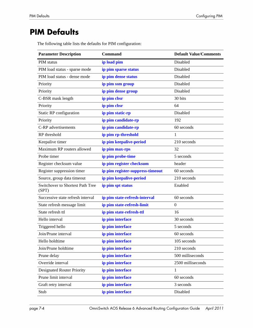
PIM Defaults Configuring PIM
PIM DefaultsThe following table lists the defaults for PIM configuration:
Parameter Description Command Default Value/Comments
PIM status ip load pim Disabled
PIM load status - sparse mode ip pim sparse status Disabled
PIM load status - dense mode ip pim dense status Disabled
Priority ip pim ssm group Disabled
Priority ip pim dense group Disabled
C-BSR mask length ip pim cbsr 30 bits
Priority ip pim cbsr 64
Static RP configuration ip pim static-rp Disabled
Priority ip pim candidate-rp 192
C-RP advertisements ip pim candidate-rp 60 seconds
RP threshold ip pim rp-threshold 1
Keepalive timer ip pim keepalive-period 210 seconds
Maximum RP routers allowed ip pim max-rps 32
Probe timer ip pim probe-time 5 seconds
Register checksum value ip pim register checksum header
Register suppression timer ip pim register-suppress-timeout 60 seconds
Source, group data timeout ip pim keepalive-period 210 seconds
Switchover to Shortest Path Tree (SPT)
ip pim spt status Enabled
Successive state refresh interval ip pim state-refresh-interval 60 seconds
State refresh message limit ip pim state-refresh-limit 0
State refresh ttl ip pim state-refresh-ttl 16
Hello interval ip pim interface 30 seconds
Triggered hello ip pim interface 5 seconds
Join/Prune interval ip pim interface 60 seconds
Hello holdtime ip pim interface 105 seconds
Join/Prune holdtime ip pim interface 210 seconds
Prune delay ip pim interface 500 milliseconds
Override interval ip pim interface 2500 milliseconds
Designated Router Priority ip pim interface 1
Prune limit interval ip pim interface 60 seconds
Graft retry interval ip pim interface 3 seconds
Stub ip pim interface Disabled
page 7-4 OmniSwitch AOS Release 6 Advanced Routing Configuration Guide April 2011
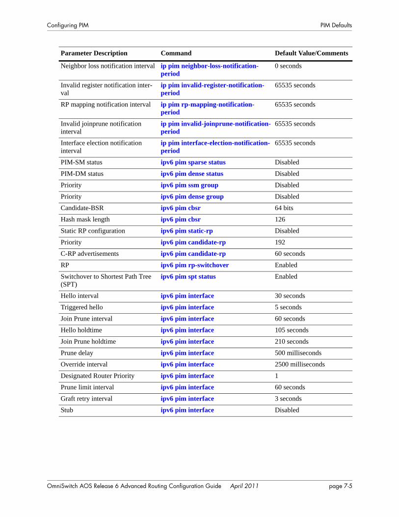
Configuring PIM PIM Defaults
Neighbor loss notification interval ip pim neighbor-loss-notification-period
0 seconds
Invalid register notification inter-val
ip pim invalid-register-notification-period
65535 seconds
RP mapping notification interval ip pim rp-mapping-notification-period
65535 seconds
Invalid joinprune notification interval
ip pim invalid-joinprune-notification-period
65535 seconds
Interface election notification interval
ip pim interface-election-notification-period
65535 seconds
PIM-SM status ipv6 pim sparse status Disabled
PIM-DM status ipv6 pim dense status Disabled
Priority ipv6 pim ssm group Disabled
Priority ipv6 pim dense group Disabled
Candidate-BSR ipv6 pim cbsr 64 bits
Hash mask length ipv6 pim cbsr 126
Static RP configuration ipv6 pim static-rp Disabled
Priority ipv6 pim candidate-rp 192
C-RP advertisements ipv6 pim candidate-rp 60 seconds
RP ipv6 pim rp-switchover Enabled
Switchover to Shortest Path Tree (SPT)
ipv6 pim spt status Enabled
Hello interval ipv6 pim interface 30 seconds
Triggered hello ipv6 pim interface 5 seconds
Join Prune interval ipv6 pim interface 60 seconds
Hello holdtime ipv6 pim interface 105 seconds
Join Prune holdtime ipv6 pim interface 210 seconds
Prune delay ipv6 pim interface 500 milliseconds
Override interval ipv6 pim interface 2500 milliseconds
Designated Router Priority ipv6 pim interface 1
Prune limit interval ipv6 pim interface 60 seconds
Graft retry interval ipv6 pim interface 3 seconds
Stub ipv6 pim interface Disabled
Parameter Description Command Default Value/Comments
OmniSwitch AOS Release 6 Advanced Routing Configuration Guide April 2011 page 7-5
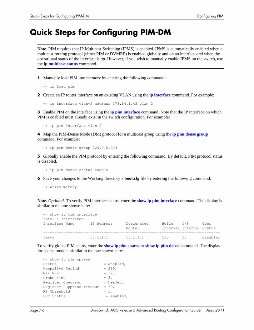
Quick Steps for Configuring PIM-DM Configuring PIM
Quick Steps for Configuring PIM-DM
Note. PIM requires that IP Multicast Switching (IPMS) is enabled. IPMS is automatically enabled when a multicast routing protocol (either PIM or DVMRP) is enabled globally and on an interface and when the operational status of the interface is up. However, if you wish to manually enable IPMS on the switch, use the ip multicast status command.
1 Manually load PIM into memory by entering the following command:
-> ip load pim
2 Create an IP router interface on an existing VLAN using the ip interface command. For example:
-> ip interface vlan-2 address 178.14.1.43 vlan 2
3 Enable PIM on the interface using the ip pim interface command. Note that the IP interface on which PIM is enabled must already exist in the switch configuration. For example:
-> ip pim interface vlan-2
4 Map the PIM-Dense Mode (DM) protocol for a multicast group using the ip pim dense group command. For example:
-> ip pim dense group 224.0.0.0/4
5 Globally enable the PIM protocol by entering the following command. By default, PIM protocol status is disabled.
-> ip pim dense status enable
6 Save your changes to the Working directory’s boot.cfg file by entering the following command:
-> write memory
Note. Optional. To verify PIM interface status, enter the show ip pim interface command. The display is similar to the one shown here:
-> show ip pim interfaceTotal 1 InterfacesInterface Name IP Address Designated Hello J/P Oper Router Interval Interval Status--------------------+---------------+---------------+--------+--------+--------tesvl 50.1.1.1 50.1.1.1 100 10 disabled
To verify global PIM status, enter the show ip pim sparse or show ip pim dense command. The display for sparse mode is similar to the one shown here:
-> show ip pim sparseStatus = enabled,Keepalive Period = 210,Max RPs = 32,Probe Time = 5,Register Checksum = header,Register Suppress Timeout = 60,RP Threshold = 1,SPT Status = enabled,
page 7-6 OmniSwitch AOS Release 6 Advanced Routing Configuration Guide April 2011
Configuring PIM Quick Steps for Configuring PIM-DM
The display for dense mode is similar to the one shown here:
-> show ip pim denseStatus = enabled,Source Lifetime = 210,State Refresh Interval = 60,State Refresh Limit Interval = 0,State Refresh TTL = 16
(additional table output not shown)
For more information about these displays, see the “PIM Commands” chapter in the OmniSwitch CLI Reference Guide.
OmniSwitch AOS Release 6 Advanced Routing Configuration Guide April 2011 page 7-7

PIM Overview Configuring PIM
PIM OverviewProtocol-Independent Multicast (PIM) is an IP multicast routing protocol that uses routing information provided by unicast routing protocols such as RIP and OSPF. Note that PIM is not dependent on any particular unicast routing protocol.
Downstream routers must explicitly join PIM distribution trees in order to receive multicast streams on behalf of receivers or other downstream PIM routers. This paradigm of receiver-initiated forwarding makes PIM ideal for network environments where receiver groups are thinly populated and bandwidth conservation is a concern, such as in wide area networks (WANs).
Note. The OmniSwitch supports PIM-DM and PIM-SMv2 but is not compatible with PIM-SMv1.
PIM-Sparse Mode (PIM-SM)Sparse mode PIM (PIM-SM) contrasts with flood-and-prune dense mode multicast protocols, such as DVMRP and PIM-Dense Mode (PIM-DM), in that multicast forwarding in PIM is initiated only via specific requests, referred to as Join messages.
The following sections provide basic descriptions for key components used when configuring a PIM-SM network. These components include the following:
• Rendezvous Points (RPs) and Candidate Rendezvous Points (C-RPs)• Bootstrap Routers (BSRs) and Candidate Bootstrap Routers (C-BSRs)• Designated Routers (DRs)• Shared Trees, also referred to as Rendezvous Point Trees (RPTs)• Avoiding Register Encapsulation
Rendezvous Points (RPs)In PIM-SM, shared distribution trees are rooted at a common forwarding router, referred to as a Rendez-vous Point (RP). The RP unencapsulates Register messages and forwards multicast packets natively down established distribution trees to receivers. The resulting topology is referred to as the RP Tree (RPT).
For an illustrated example of an RPT and the RP’s role in a simple PIM-SM environment, refer to “Shared (or RP) Trees” on page 7-9.
Candidate Rendezvous Points (C-RPs)
A Candidate Rendezvous Point (C-RP) is a PIM-enabled router that sends periodic C-RP advertisements to the Bootstrap Router (BSR). When a BSR receives a C-RP advertisement, the BSR may include the C-RP in its RP-set. For more information on the BSR and RP-set, refer to page 7-9.
page 7-8 OmniSwitch AOS Release 6 Advanced Routing Configuration Guide April 2011
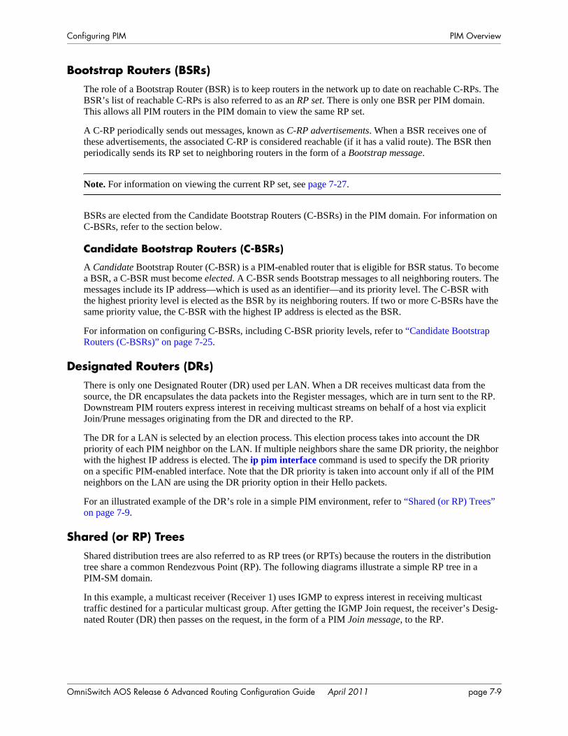
Configuring PIM PIM Overview
Bootstrap Routers (BSRs)The role of a Bootstrap Router (BSR) is to keep routers in the network up to date on reachable C-RPs. The BSR’s list of reachable C-RPs is also referred to as an RP set. There is only one BSR per PIM domain. This allows all PIM routers in the PIM domain to view the same RP set.
A C-RP periodically sends out messages, known as C-RP advertisements. When a BSR receives one of these advertisements, the associated C-RP is considered reachable (if it has a valid route). The BSR then periodically sends its RP set to neighboring routers in the form of a Bootstrap message.
Note. For information on viewing the current RP set, see page 7-27.
BSRs are elected from the Candidate Bootstrap Routers (C-BSRs) in the PIM domain. For information on C-BSRs, refer to the section below.
Candidate Bootstrap Routers (C-BSRs)
A Candidate Bootstrap Router (C-BSR) is a PIM-enabled router that is eligible for BSR status. To become a BSR, a C-BSR must become elected. A C-BSR sends Bootstrap messages to all neighboring routers. The messages include its IP address—which is used as an identifier—and its priority level. The C-BSR with the highest priority level is elected as the BSR by its neighboring routers. If two or more C-BSRs have the same priority value, the C-BSR with the highest IP address is elected as the BSR.
For information on configuring C-BSRs, including C-BSR priority levels, refer to “Candidate Bootstrap Routers (C-BSRs)” on page 7-25.
Designated Routers (DRs)There is only one Designated Router (DR) used per LAN. When a DR receives multicast data from the source, the DR encapsulates the data packets into the Register messages, which are in turn sent to the RP. Downstream PIM routers express interest in receiving multicast streams on behalf of a host via explicit Join/Prune messages originating from the DR and directed to the RP.
The DR for a LAN is selected by an election process. This election process takes into account the DR priority of each PIM neighbor on the LAN. If multiple neighbors share the same DR priority, the neighbor with the highest IP address is elected. The ip pim interface command is used to specify the DR priority on a specific PIM-enabled interface. Note that the DR priority is taken into account only if all of the PIM neighbors on the LAN are using the DR priority option in their Hello packets.
For an illustrated example of the DR’s role in a simple PIM environment, refer to “Shared (or RP) Trees” on page 7-9.
Shared (or RP) TreesShared distribution trees are also referred to as RP trees (or RPTs) because the routers in the distribution tree share a common Rendezvous Point (RP). The following diagrams illustrate a simple RP tree in a PIM-SM domain.
In this example, a multicast receiver (Receiver 1) uses IGMP to express interest in receiving multicast traffic destined for a particular multicast group. After getting the IGMP Join request, the receiver’s Desig-nated Router (DR) then passes on the request, in the form of a PIM Join message, to the RP.
OmniSwitch AOS Release 6 Advanced Routing Configuration Guide April 2011 page 7-9
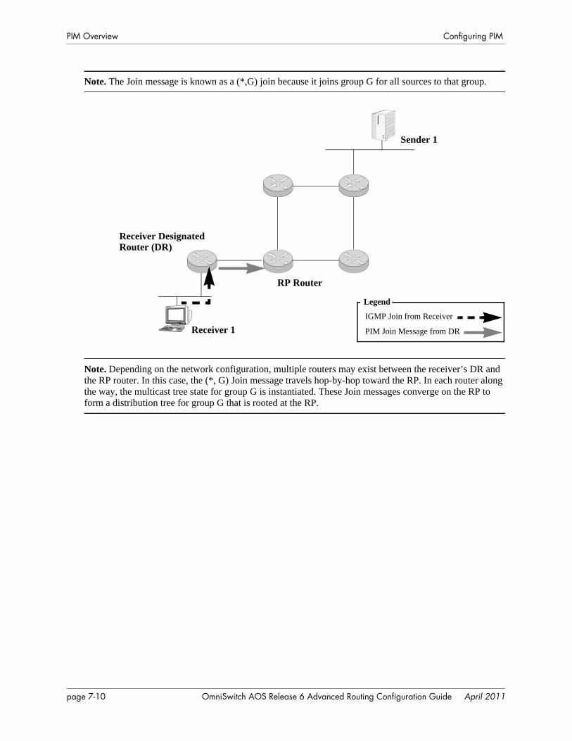
PIM Overview Configuring PIM
Note. The Join message is known as a (*,G) join because it joins group G for all sources to that group.
Note. Depending on the network configuration, multiple routers may exist between the receiver’s DR and the RP router. In this case, the (*, G) Join message travels hop-by-hop toward the RP. In each router along the way, the multicast tree state for group G is instantiated. These Join messages converge on the RP to form a distribution tree for group G that is rooted at the RP.
PIM Join Message from DR
Legend
Sender 1
Receiver 1
RP Router
Receiver Designated Router (DR)
IGMP Join from Receiver
page 7-10 OmniSwitch AOS Release 6 Advanced Routing Configuration Guide April 2011
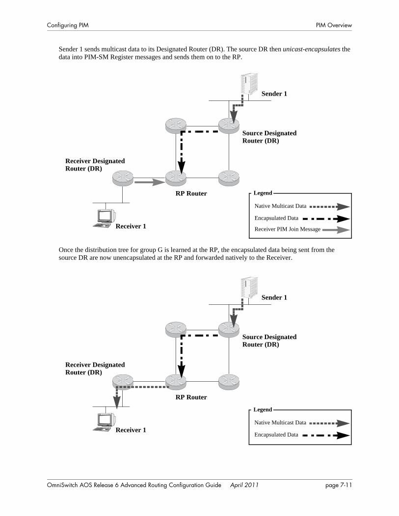
Configuring PIM PIM Overview
Sender 1 sends multicast data to its Designated Router (DR). The source DR then unicast-encapsulates the data into PIM-SM Register messages and sends them on to the RP.
Once the distribution tree for group G is learned at the RP, the encapsulated data being sent from the source DR are now unencapsulated at the RP and forwarded natively to the Receiver.
Sender 1
Receiver 1
RP Router
Source Designated Router (DR)
Receiver Designated Router (DR)
Receiver PIM Join Message
Legend
Encapsulated Data
Native Multicast Data
Sender 1
Receiver 1
RP Router
Source Designated Router (DR)
Receiver Designated Router (DR)
Legend
Encapsulated Data
Native Multicast Data
OmniSwitch AOS Release 6 Advanced Routing Configuration Guide April 2011 page 7-11
PIM Overview Configuring PIM
Avoiding Register EncapsulationSwitching to a Shortest Path Tree (SPT) topology allows PIM routers to avoid Register encapsulation of data packets that occurs in an RPT. Register encapsulation is inefficient for the following reasons:
• The encapsulation and unencapsulation of Register messages tax router resources. Hardware routing does not support encapsulation and unencapsulation.
• Register encapsulation may require that data travel unnecessarily over long distances. For example, data may have to travel “out of their way” to the RP before turning back down the shared tree in order to reach a receiver.
For some applications, this increased latency is undesirable. There are two methods for avoiding register encapsulation: RP initiation of (S, G) source-specific Join messages and switchover to a Shortest Path Tree (SPT). For more information, refer to the sections below.
PIM-Dense Mode (PIM-DM)PIM-DM is a multicast routing protocol that defines a multicast routing algorithm for multicast groups densely distributed across a network. PIM-DM uses the underlying unicast routing information base to flood multicast datagrams to all multicast routers. Prune messages are used to prevent future messages from propagating to routers with no group membership information. It employs the same packet formats as PIM-SM.
PIM-DM assumes that when a multicast source starts sending, all downstream systems receive multicast datagrams. Multicast datagrams are initially flooded to all network areas. PIM-DM utilizes Reverse Path Forwarding to prevent looping of multicast datagrams while flooding. If some areas of the network do not have group members, PIM-DM will prune off the forwarding branch by instantiating the prune state.
PIM-DM differs from PIM-SM in two essential ways:
• There are no periodic joins transmitted, only explicitly triggered prunes and grafts.
• There is no Rendezvous Point (RP). This is particularly important in networks that cannot tolerate a single point of failure.
Note. A PIM router cannot differentiate a PIM-DM neighbor and a PIM-SM neighbor based on Hello messages, and PIM-DM is not intended to interact directly with a PIM-SM router.
page 7-12 OmniSwitch AOS Release 6 Advanced Routing Configuration Guide April 2011
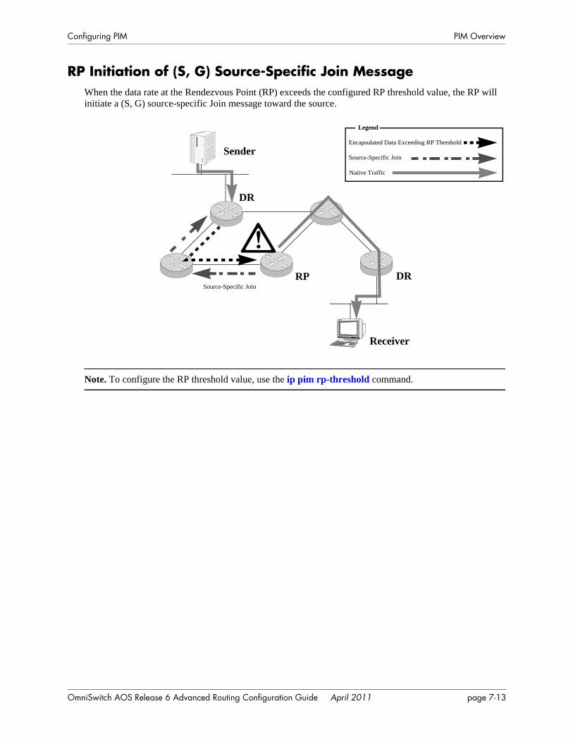
Configuring PIM PIM Overview
RP Initiation of (S, G) Source-Specific Join MessageWhen the data rate at the Rendezvous Point (RP) exceeds the configured RP threshold value, the RP will initiate a (S, G) source-specific Join message toward the source.
Note. To configure the RP threshold value, use the ip pim rp-threshold command.
Sender
Receiver
RP DR
Legend
Source-Specific Join
DR
!
Encapsulated Data Exceeding RP Threshold
Source-Specific Join
Native Traffic
OmniSwitch AOS Release 6 Advanced Routing Configuration Guide April 2011 page 7-13
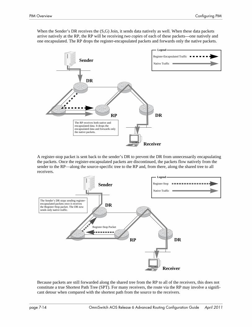
PIM Overview Configuring PIM
When the Sender’s DR receives the (S,G) Join, it sends data natively as well. When these data packets arrive natively at the RP, the RP will be receiving two copies of each of these packets—one natively and one encapsulated. The RP drops the register-encapsulated packets and forwards only the native packets.
A register-stop packet is sent back to the sender’s DR to prevent the DR from unnecessarily encapsulating the packets. Once the register-encapsulated packets are discontinued, the packets flow natively from the sender to the RP—along the source-specific tree to the RP and, from there, along the shared tree to all receivers.
Because packets are still forwarded along the shared tree from the RP to all of the receivers, this does not constitute a true Shortest Path Tree (SPT). For many receivers, the route via the RP may involve a signifi-cant detour when compared with the shortest path from the source to the receivers.
Sender
Receiver
RP DR
Legend
DR
Register-Encapsulated Traffic
Native Traffic
The RP receives both native and encapsulated data. It drops theencapsulated data and forwards onlythe native packets.
Sender
Receiver
RP DR
DR
Legend
Register-Stop
Native Traffic
Register-Stop Packet
The Sender’s DR stops sending register-encapsulated packets once it receivesthe Register-Stop packet. The DR now sends only native traffic.
page 7-14 OmniSwitch AOS Release 6 Advanced Routing Configuration Guide April 2011
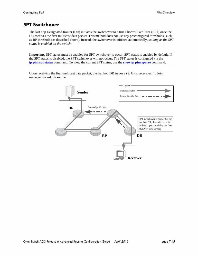
Configuring PIM PIM Overview
SPT SwitchoverThe last hop Designated Router (DR) initiates the switchover to a true Shortest Path Tree (SPT) once the DR receives the first multicast data packet. This method does not use any preconfigured thresholds, such as RP threshold (as described above). Instead, the switchover is initiated automatically, as long as the SPT status is enabled on the switch.
Important. SPT status must be enabled for SPT switchover to occur. SPT status is enabled by default. If the SPT status is disabled, the SPT switchover will not occur. The SPT status is configured via the ip pim spt status command. To view the current SPT status, use the show ip pim sparse command.
Upon receiving the first multicast data packet, the last hop DR issues a (S, G) source-specific Join message toward the source.
Sender
Receiver
RP DR
DR
SPT switchover is enabled at the last hop DR; the switchover is initiated upon receiving the first multicast data packet.
Legend
Source-Specific Join
Multicast Traffic
Source-Specific Join
OmniSwitch AOS Release 6 Advanced Routing Configuration Guide April 2011 page 7-15
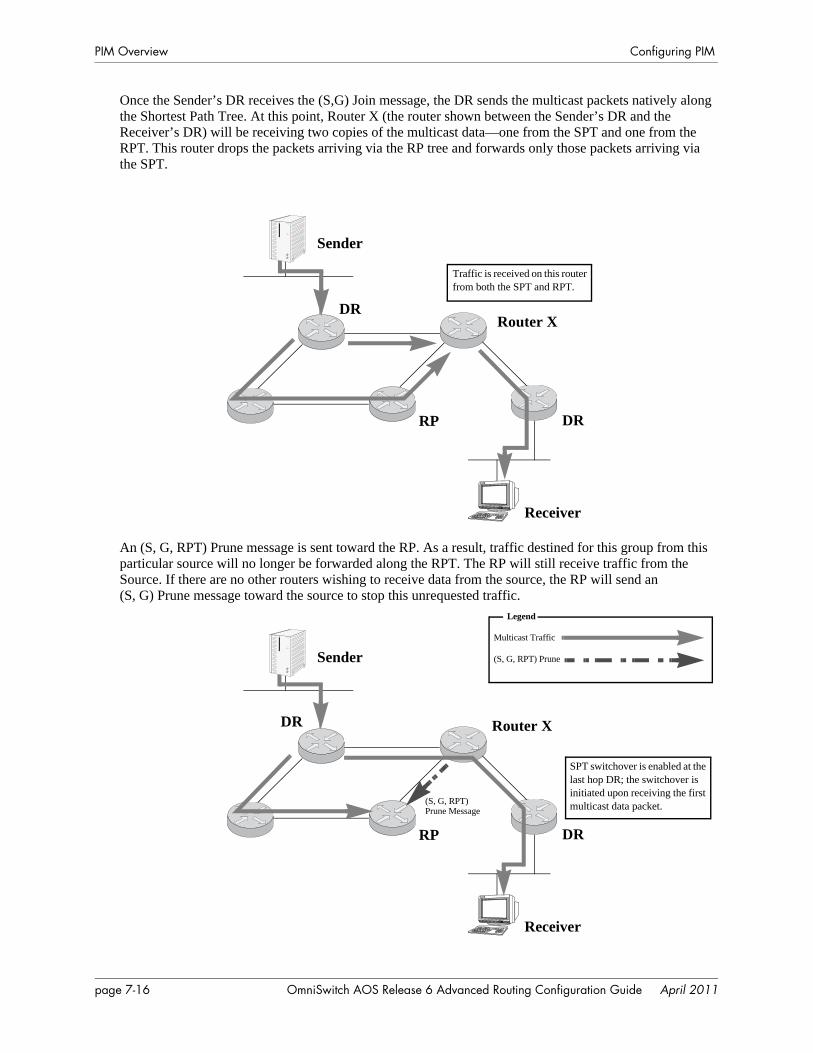
PIM Overview Configuring PIM
Once the Sender’s DR receives the (S,G) Join message, the DR sends the multicast packets natively along the Shortest Path Tree. At this point, Router X (the router shown between the Sender’s DR and the Receiver’s DR) will be receiving two copies of the multicast data—one from the SPT and one from the RPT. This router drops the packets arriving via the RP tree and forwards only those packets arriving via the SPT.
An (S, G, RPT) Prune message is sent toward the RP. As a result, traffic destined for this group from this particular source will no longer be forwarded along the RPT. The RP will still receive traffic from the Source. If there are no other routers wishing to receive data from the source, the RP will send an(S, G) Prune message toward the source to stop this unrequested traffic.
Traffic is received on this router from both the SPT and RPT.
Sender
Receiver
RP DR
DRRouter X
Sender
Receiver
RP DR
DR
SPT switchover is enabled at the last hop DR; the switchover is initiated upon receiving the first multicast data packet.
Legend
(S, G, RPT) Prune
Multicast Traffic
(S, G, RPT)
Router X
Prune Message
page 7-16 OmniSwitch AOS Release 6 Advanced Routing Configuration Guide April 2011

Configuring PIM PIM Overview
The Receiver is now receiving multicast traffic along the Shortest Path Tree between the Receiver and the Source.
PIM-SSM SupportProtocol-Independent Multicast Source-Specific Multicast (PIM-SSM) is a highly-efficient extension of PIM. SSM, using an explicit channel subscription model, allows receivers to receive multicast traffic directly from the source; an RP tree model is not used. In other words, a Shortest Path Tree (SPT) between the receiver and the source is created without the use of a Rendezvous Point (RP).
By default, PIM software supports Source-Specific Multicast. No additional user configuration is required. PIM-SSM is automatically enabled and operational as long as PIM is loaded (see page 7-6) and IGMPv3 source-specific joins are received within the SSM address range.
For detailed information on PIM-SSM and Source-Specific Multicast, refer to the IETF Internet Drafts draft-ietf-pim-sm-v2-new-05.txt and draft-ietf-ssm-arch-04.txt, as well as RFC 3569, “An Overview of Source-Specific Multicast (SSM).”
Note. For networks using IGMP proxy, be sure that the IGMP proxy version is set to Version 3. Otherwise, PIM-SSM will not function. For information on configuring the IGMP version, refer to the ip multicast version command.
Source-Specific Multicast AddressesThe multicast address range from 232.0.0.0 through 232.255.255.255 have been reserved by the Internet Assigned Numbers Authority (IANA) as Source-Specific Multicast (SSM) destination addresses. The PIM-Source-Specific Multicast (SSM) mode for the default SSM address range is not enabled automati-cally and needs to be configured manually to support SSM. Addresses within this range are reserved for use by source-specific applications and protocols (e.g., PIM-SSM). These addresses cannot be used for any other functions or protocols. However, you can also map additional multicast address ranges for the SSM group.
Sender
Receiver
RP DR
DR
OmniSwitch AOS Release 6 Advanced Routing Configuration Guide April 2011 page 7-17
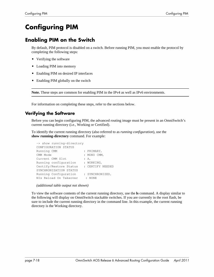
Configuring PIM Configuring PIM
Configuring PIM
Enabling PIM on the SwitchBy default, PIM protocol is disabled on a switch. Before running PIM, you must enable the protocol by completing the following steps:
• Verifying the software
• Loading PIM into memory
• Enabling PIM on desired IP interfaces
• Enabling PIM globally on the switch
Note. These steps are common for enabling PIM in the IPv4 as well as IPv6 environments.
For information on completing these steps, refer to the sections below.
Verifying the SoftwareBefore you can begin configuring PIM, the advanced routing image must be present in an OmniSwitch’s current running directory (i.e., Working or Certified).
To identify the current running directory (also referred to as running configuration), use the show running-directory command. For example:
-> show running-directoryCONFIGURATION STATUSRunning CMM : PRIMARY,CMM Mode : MONO CMM,Current CMM Slot : A,Running configuration : WORKING,Certify/Restore Status : CERTIFY NEEDEDSYNCHRONIZATION STATUSRunning Configuration : SYNCHRONIZED,NIs Reload On Takeover : NONE
(additional table output not shown)
To view the software contents of the current running directory, use the ls command. A display similar to the following will display on OmniSwitch stackable switches. If you are currently in the root flash, be sure to include the current running directory in the command line. In this example, the current running directory is the Working directory.
page 7-18 OmniSwitch AOS Release 6 Advanced Routing Configuration Guide April 2011
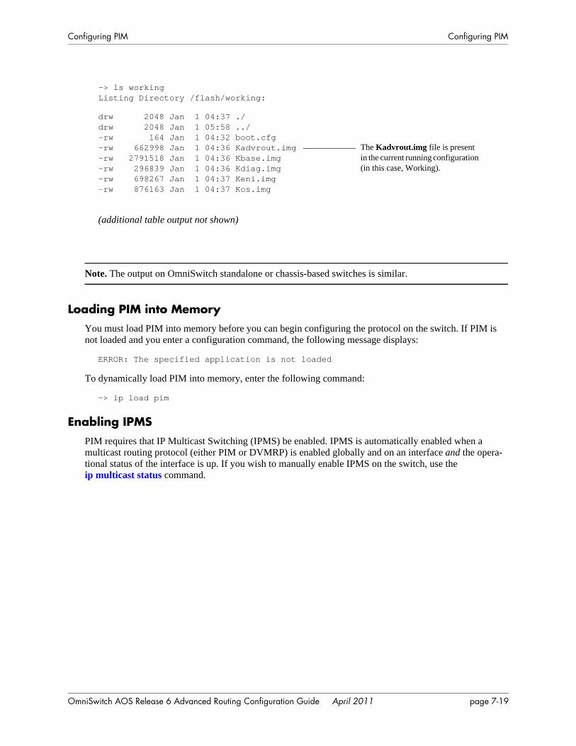
Configuring PIM Configuring PIM
Note. The output on OmniSwitch standalone or chassis-based switches is similar.
Loading PIM into MemoryYou must load PIM into memory before you can begin configuring the protocol on the switch. If PIM is not loaded and you enter a configuration command, the following message displays:
ERROR: The specified application is not loaded
To dynamically load PIM into memory, enter the following command:
-> ip load pim
Enabling IPMSPIM requires that IP Multicast Switching (IPMS) be enabled. IPMS is automatically enabled when a multicast routing protocol (either PIM or DVMRP) is enabled globally and on an interface and the opera-tional status of the interface is up. If you wish to manually enable IPMS on the switch, use the ip multicast status command.
-> ls workingListing Directory /flash/working:
drw 2048 Jan 1 04:37 ./drw 2048 Jan 1 05:58 ../-rw 164 Jan 1 04:32 boot.cfg-rw 662998 Jan 1 04:36 Kadvrout.img-rw 2791518 Jan 1 04:36 Kbase.img-rw 296839 Jan 1 04:36 Kdiag.img-rw 698267 Jan 1 04:37 Keni.img-rw 876163 Jan 1 04:37 Kos.img
(additional table output not shown)
The Kadvrout.img file is present in the current running configuration (in this case, Working).
OmniSwitch AOS Release 6 Advanced Routing Configuration Guide April 2011 page 7-19
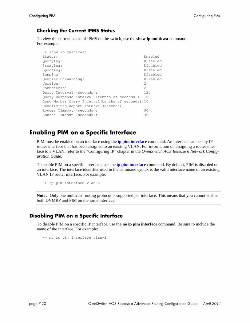
Configuring PIM Configuring PIM
Checking the Current IPMS Status
To view the current status of IPMS on the switch, use the show ip multicast command. For example:
-> show ip multicastStatus: EnabledQuerying: DisabledProxying: DisabledSpoofing: DisabledZapping: DisabledQuerier Forwarding: DisabledVersion: 2Robustness: 2Query Interval (seconds): 125Query Response Interval (tenths of seconds): 100Last Member Query Interval(tenths of seconds):10Unsolicited Report Interval(seconds): 1Router Timeout (seconds): 90Source Timeout (seconds): 30
Enabling PIM on a Specific InterfacePIM must be enabled on an interface using the ip pim interface command. An interface can be any IP router interface that has been assigned to an existing VLAN. For information on assigning a router inter-face to a VLAN, refer to the “Configuring IP” chapter in the OmniSwitch AOS Release 6 Network Config-uration Guide.
To enable PIM on a specific interface, use the ip pim interface command. By default, PIM is disabled on an interface. The interface identifier used in the command syntax is the valid interface name of an existing VLAN IP router interface. For example:
-> ip pim interface vlan-2
Note. Only one multicast routing protocol is supported per interface. This means that you cannot enable both DVMRP and PIM on the same interface.
Disabling PIM on a Specific InterfaceTo disable PIM on a specific IP interface, use the no ip pim interface command. Be sure to include the name of the interface. For example:
-> no ip pim interface vlan-2
page 7-20 OmniSwitch AOS Release 6 Advanced Routing Configuration Guide April 2011
Configuring PIM Configuring PIM
Viewing PIM Status and Parameters for a Specific InterfaceTo view the current PIM interface information—which includes IP addresses for PIM-enabled interfaces, Hello and Join/Prune intervals, and current operational status—use the show ip pim interface command. For example:
Enabling PIM Mode on the SwitchTo globally enable PIM-Sparse Mode on the switch, use the ip pim sparse status command. Enter the command syntax as shown below:
-> ip pim sparse status enable
To globally enable PIM-Dense Mode on the switch, use the ip pim dense status command. Enter the command syntax as shown below:
-> ip pim dense status enable
Disabling PIM Mode on the SwitchTo globally disable PIM-Sparse Mode on the switch, use the ip pim sparse status command. Enter the command syntax as shown below:
-> ip pim sparse status disable
To globally disable PIM-Dense Mode on the switch, use the ip pim dense status command. Enter the command syntax as shown below:
-> ip pim dense status disable
-> show ip pim interfaceTotal 1 InterfacesInterface Name IP Address Designated Hello J/P Oper Router Interval Interval Status--------------------+---------------+---------------+--------+--------+-------tesvl 50.1.1.1 50.1.1.1 100 10 disabled
The Interface Name used to identify the PIM enabled interface is listed in the PIM interface table.
The IP address of the Designated Router for the interface is displayed.
OmniSwitch AOS Release 6 Advanced Routing Configuration Guide April 2011 page 7-21
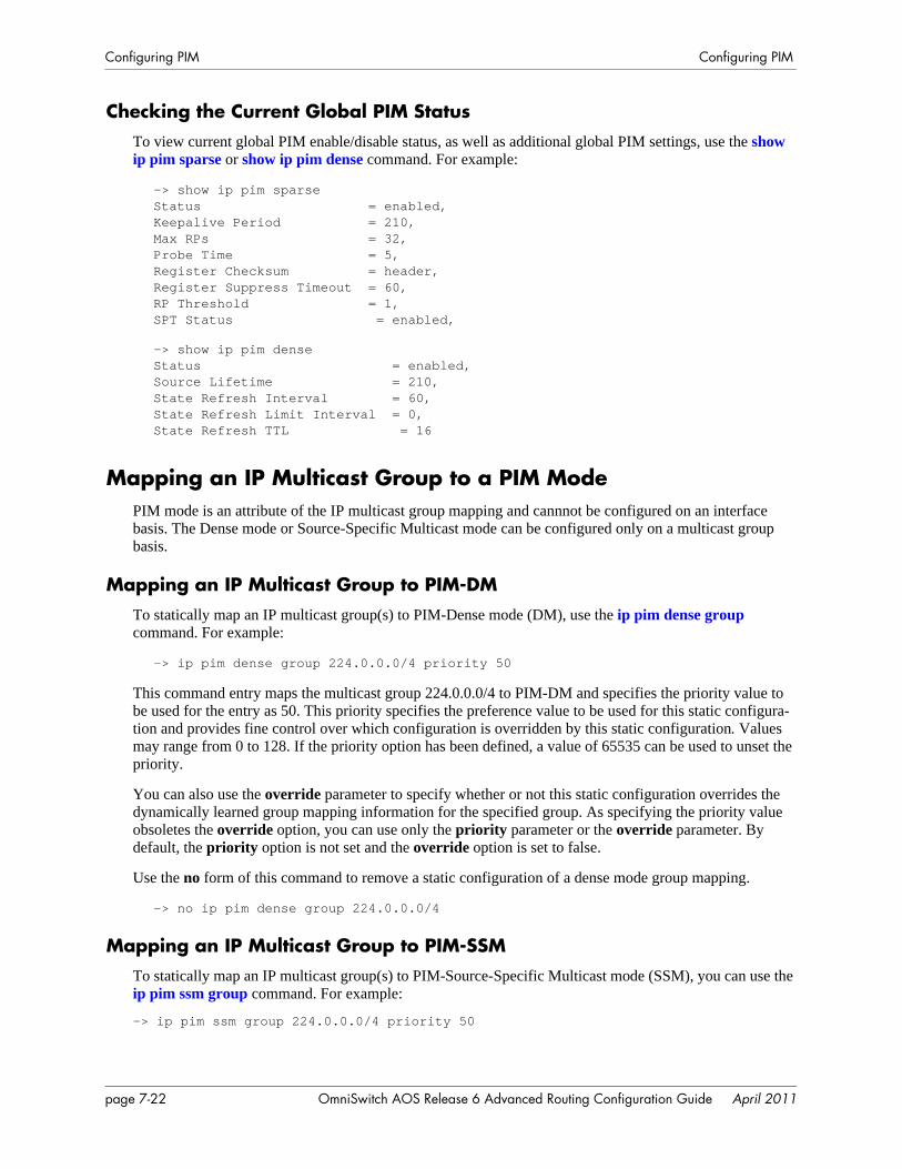
Configuring PIM Configuring PIM
Checking the Current Global PIM StatusTo view current global PIM enable/disable status, as well as additional global PIM settings, use the show ip pim sparse or show ip pim dense command. For example:
-> show ip pim sparseStatus = enabled,Keepalive Period = 210,Max RPs = 32,Probe Time = 5,Register Checksum = header,Register Suppress Timeout = 60,RP Threshold = 1,SPT Status = enabled,
-> show ip pim denseStatus = enabled,Source Lifetime = 210,State Refresh Interval = 60,State Refresh Limit Interval = 0,State Refresh TTL = 16
Mapping an IP Multicast Group to a PIM ModePIM mode is an attribute of the IP multicast group mapping and cannnot be configured on an interface basis. The Dense mode or Source-Specific Multicast mode can be configured only on a multicast group basis.
Mapping an IP Multicast Group to PIM-DMTo statically map an IP multicast group(s) to PIM-Dense mode (DM), use the ip pim dense group command. For example:
-> ip pim dense group 224.0.0.0/4 priority 50
This command entry maps the multicast group 224.0.0.0/4 to PIM-DM and specifies the priority value to be used for the entry as 50. This priority specifies the preference value to be used for this static configura-tion and provides fine control over which configuration is overridden by this static configuration. Values may range from 0 to 128. If the priority option has been defined, a value of 65535 can be used to unset the priority.
You can also use the override parameter to specify whether or not this static configuration overrides the dynamically learned group mapping information for the specified group. As specifying the priority value obsoletes the override option, you can use only the priority parameter or the override parameter. By default, the priority option is not set and the override option is set to false.
Use the no form of this command to remove a static configuration of a dense mode group mapping.
-> no ip pim dense group 224.0.0.0/4
Mapping an IP Multicast Group to PIM-SSMTo statically map an IP multicast group(s) to PIM-Source-Specific Multicast mode (SSM), you can use the ip pim ssm group command. For example:
-> ip pim ssm group 224.0.0.0/4 priority 50
page 7-22 OmniSwitch AOS Release 6 Advanced Routing Configuration Guide April 2011
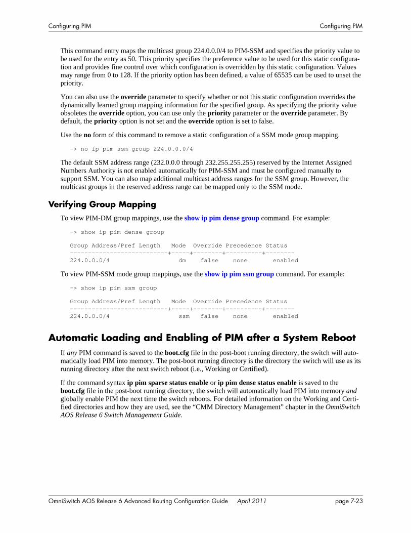
Configuring PIM Configuring PIM
This command entry maps the multicast group 224.0.0.0/4 to PIM-SSM and specifies the priority value to be used for the entry as 50. This priority specifies the preference value to be used for this static configura-tion and provides fine control over which configuration is overridden by this static configuration. Values may range from 0 to 128. If the priority option has been defined, a value of 65535 can be used to unset the priority.
You can also use the override parameter to specify whether or not this static configuration overrides the dynamically learned group mapping information for the specified group. As specifying the priority value obsoletes the override option, you can use only the priority parameter or the override parameter. By default, the priority option is not set and the override option is set to false.
Use the no form of this command to remove a static configuration of a SSM mode group mapping.
-> no ip pim ssm group 224.0.0.0/4
The default SSM address range (232.0.0.0 through 232.255.255.255) reserved by the Internet Assigned Numbers Authority is not enabled automatically for PIM-SSM and must be configured manually to support SSM. You can also map additional multicast address ranges for the SSM group. However, the multicast groups in the reserved address range can be mapped only to the SSM mode.
Verifying Group MappingTo view PIM-DM group mappings, use the show ip pim dense group command. For example:
-> show ip pim dense group
Group Address/Pref Length Mode Override Precedence Status---------------------------+-----+--------+----------+--------224.0.0.0/4 dm false none enabled
To view PIM-SSM mode group mappings, use the show ip pim ssm group command. For example:
-> show ip pim ssm group
Group Address/Pref Length Mode Override Precedence Status---------------------------+-----+--------+----------+--------224.0.0.0/4 ssm false none enabled
Automatic Loading and Enabling of PIM after a System RebootIf any PIM command is saved to the boot.cfg file in the post-boot running directory, the switch will auto-matically load PIM into memory. The post-boot running directory is the directory the switch will use as its running directory after the next switch reboot (i.e., Working or Certified).
If the command syntax ip pim sparse status enable or ip pim dense status enable is saved to the boot.cfg file in the post-boot running directory, the switch will automatically load PIM into memory and globally enable PIM the next time the switch reboots. For detailed information on the Working and Certi-fied directories and how they are used, see the “CMM Directory Management” chapter in the OmniSwitch AOS Release 6 Switch Management Guide.
OmniSwitch AOS Release 6 Advanced Routing Configuration Guide April 2011 page 7-23
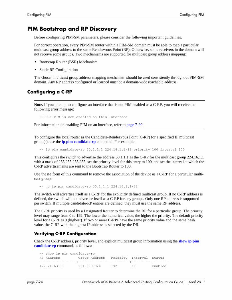
Configuring PIM Configuring PIM
PIM Bootstrap and RP DiscoveryBefore configuring PIM-SM parameters, please consider the following important guidelines.
For correct operation, every PIM-SM router within a PIM-SM domain must be able to map a particular multicast group address to the same Rendezvous Point (RP). Otherwise, some receivers in the domain will not receive some groups. Two mechanisms are supported for multicast group address mapping:
• Bootstrap Router (BSR) Mechanism
• Static RP Configuration
The chosen multicast group address mapping mechanism should be used consistently throughout PIM-SM domain. Any RP address configured or learned must be a domain-wide reachable address.
Configuring a C-RP
Note. If you attempt to configure an interface that is not PIM enabled as a C-RP, you will receive the following error message:
ERROR: PIM is not enabled on this Interface
For information on enabling PIM on an interface, refer to page 7-20.
To configure the local router as the Candidate-Rendezvous Point (C-RP) for a specified IP multicast group(s), use the ip pim candidate-rp command. For example:
-> ip pim candidate-rp 50.1.1.1 224.16.1.1/32 priority 100 interval 100
This configures the switch to advertise the address 50.1.1.1 as the C-RP for the multicast group 224.16.1.1 with a mask of 255.255.255.255, set the priority level for this entry to 100, and set the interval at which the C-RP advertisements are sent to the Bootstrap Router to 100.
Use the no form of this command to remove the association of the device as a C-RP for a particular multi-cast group.
-> no ip pim candidate-rp 50.1.1.1 224.16.1.1/32
The switch will advertise itself as a C-RP for the explicitly defined multicast group. If no C-RP address is defined, the switch will not advertise itself as a C-RP for any groups. Only one RP address is supported per switch. If multiple candidate-RP entries are defined, they must use the same RP address.
The C-RP priority is used by a Designated Router to determine the RP for a particular group. The priority level may range from 0 to 192. The lower the numerical value, the higher the priority. The default priority level for a C-RP is 0 (highest). If two or more C-RPs have the same priority value and the same hash value, the C-RP with the highest IP address is selected by the DR.
Verifying C-RP Configuration
Check the C-RP address, priority level, and explicit multicast group information using the show ip pim candidate-rp command, as follows:
-> show ip pim candidate-rpRP Address Group Address Priority Interval Status------------------+---------------+---------+---------+--------172.21.63.11 224.0.0.0/4 192 60 enabled
page 7-24 OmniSwitch AOS Release 6 Advanced Routing Configuration Guide April 2011
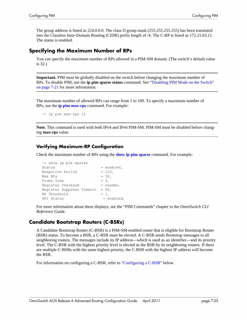
Configuring PIM Configuring PIM
The group address is listed as 224.0.0.0. The class D group mask (255.255.255.255) has been translated into the Classless Inter-Domain Routing (CIDR) prefix length of /4. The C-RP is listed as 172.21.63.11. The status is enabled.
Specifying the Maximum Number of RPsYou can specify the maximum number of RPs allowed in a PIM-SM domain. (The switch’s default value is 32.)
Important. PIM must be globally disabled on the switch before changing the maximum number of RPs. To disable PIM, use the ip pim sparse status command. See “Disabling PIM Mode on the Switch” on page 7-21 for more information.
The maximum number of allowed RPs can range from 1 to 100. To specify a maximum number ofRPs, use the ip pim max-rps command. For example:
-> ip pim max-rps 12
Note. This command is used with both IPv4 and IPv6 PIM-SM. PIM-SM must be disabled before chang-ing max-rps value.
Verifying Maximum-RP Configuration
Check the maximum number of RPs using the show ip pim sparse command. For example:
-> show ip pim sparseStatus = enabled,Keepalive Period = 210,Max RPs = 32,Probe Time = 5,Register Checksum = header,Register Suppress Timeout = 60,RP Threshold = 1,SPT Status = enabled,
For more information about these displays, see the “PIM Commands” chapter in the OmniSwitch CLI Reference Guide.
Candidate Bootstrap Routers (C-BSRs)A Candidate Bootstrap Router (C-BSR) is a PIM-SM-enabled router that is eligible for Bootstrap Router (BSR) status. To become a BSR, a C-BSR must be elected. A C-BSR sends Bootstrap messages to all neighboring routers. The messages include its IP address—which is used as an identifier—and its priority level. The C-BSR with the highest priority level is elected as the BSR by its neighboring routers. If there are multiple C-BSRs with the same highest priority, the C-BSR with the highest IP address will become the BSR.
For information on configuring a C-BSR, refer to “Configuring a C-BSR” below.
OmniSwitch AOS Release 6 Advanced Routing Configuration Guide April 2011 page 7-25
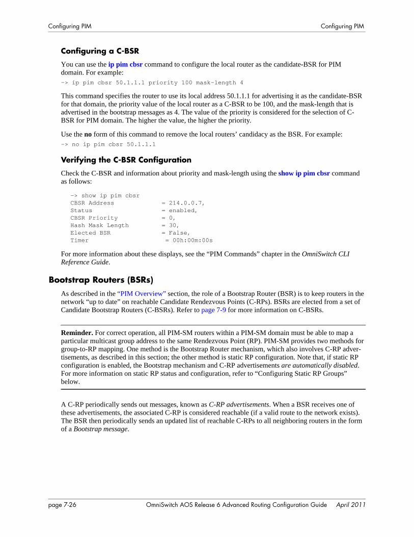
Configuring PIM Configuring PIM
Configuring a C-BSR
You can use the ip pim cbsr command to configure the local router as the candidate-BSR for PIM domain. For example:-> ip pim cbsr 50.1.1.1 priority 100 mask-length 4
This command specifies the router to use its local address 50.1.1.1 for advertising it as the candidate-BSR for that domain, the priority value of the local router as a C-BSR to be 100, and the mask-length that is advertised in the bootstrap messages as 4. The value of the priority is considered for the selection of C-BSR for PIM domain. The higher the value, the higher the priority.
Use the no form of this command to remove the local routers’ candidacy as the BSR. For example:-> no ip pim cbsr 50.1.1.1
Verifying the C-BSR Configuration
Check the C-BSR and information about priority and mask-length using the show ip pim cbsr command as follows:
-> show ip pim cbsrCBSR Address = 214.0.0.7,Status = enabled,CBSR Priority = 0,Hash Mask Length = 30,Elected BSR = False,Timer = 00h:00m:00s
For more information about these displays, see the “PIM Commands” chapter in the OmniSwitch CLI Reference Guide.
Bootstrap Routers (BSRs)As described in the “PIM Overview” section, the role of a Bootstrap Router (BSR) is to keep routers in the network “up to date” on reachable Candidate Rendezvous Points (C-RPs). BSRs are elected from a set of Candidate Bootstrap Routers (C-BSRs). Refer to page 7-9 for more information on C-BSRs.
Reminder. For correct operation, all PIM-SM routers within a PIM-SM domain must be able to map a particular multicast group address to the same Rendezvous Point (RP). PIM-SM provides two methods for group-to-RP mapping. One method is the Bootstrap Router mechanism, which also involves C-RP adver-tisements, as described in this section; the other method is static RP configuration. Note that, if static RP configuration is enabled, the Bootstrap mechanism and C-RP advertisements are automatically disabled. For more information on static RP status and configuration, refer to “Configuring Static RP Groups” below.
A C-RP periodically sends out messages, known as C-RP advertisements. When a BSR receives one of these advertisements, the associated C-RP is considered reachable (if a valid route to the network exists). The BSR then periodically sends an updated list of reachable C-RPs to all neighboring routers in the form of a Bootstrap message.
page 7-26 OmniSwitch AOS Release 6 Advanced Routing Configuration Guide April 2011
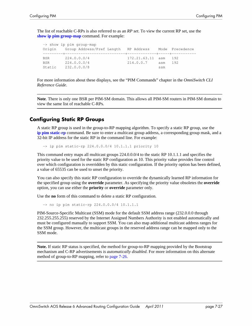
Configuring PIM Configuring PIM
The list of reachable C-RPs is also referred to as an RP set. To view the current RP set, use the show ip pim group-map command. For example:
-> show ip pim group-mapOrigin Group Address/Pref Length RP Address Mode Precedence---------+---------------------------+-------------+-----+-----------BSR 224.0.0.0/4 172.21.63.11 asm 192BSR 224.0.0.0/4 214.0.0.7 asm 192Static 232.0.0.0/8 ssm
For more information about these displays, see the “PIM Commands” chapter in the OmniSwitch CLI Reference Guide.
Note. There is only one BSR per PIM-SM domain. This allows all PIM-SM routers in PIM-SM domain to view the same list of reachable C-RPs.
Configuring Static RP GroupsA static RP group is used in the group-to-RP mapping algorithm. To specify a static RP group, use the ip pim static-rp command. Be sure to enter a multicast group address, a corresponding group mask, and a 32-bit IP address for the static RP in the command line. For example:
-> ip pim static-rp 224.0.0.0/4 10.1.1.1 priority 10
This command entry maps all multicast groups 224.0.0.0/4 to the static RP 10.1.1.1 and specifies the priority value to be used for the static RP configuration as 10. This priority value provides fine control over which configuration is overridden by this static configuration. If the priority option has been defined, a value of 65535 can be used to unset the priority.
You can also specify this static RP configuration to override the dynamically learned RP information for the specified group using the override parameter. As specifying the priority value obsoletes the override option, you can use either the priority or override parameter only.
Use the no form of this command to delete a static RP configuration.
-> no ip pim static-rp 224.0.0.0/4 10.1.1.1
PIM-Source-Specific Multicast (SSM) mode for the default SSM address range (232.0.0.0 through 232.255.255.255) reserved by the Internet Assigned Numbers Authority is not enabled automatically and must be configured manually to support SSM. You can also map additional multicast address ranges for the SSM group. However, the multicast groups in the reserved address range can be mapped only to the SSM mode.
Note. If static RP status is specified, the method for group-to-RP mapping provided by the Bootstrap mechanism and C-RP advertisements is automatically disabled. For more information on this alternate method of group-to-RP mapping, refer to page 7-26.
OmniSwitch AOS Release 6 Advanced Routing Configuration Guide April 2011 page 7-27
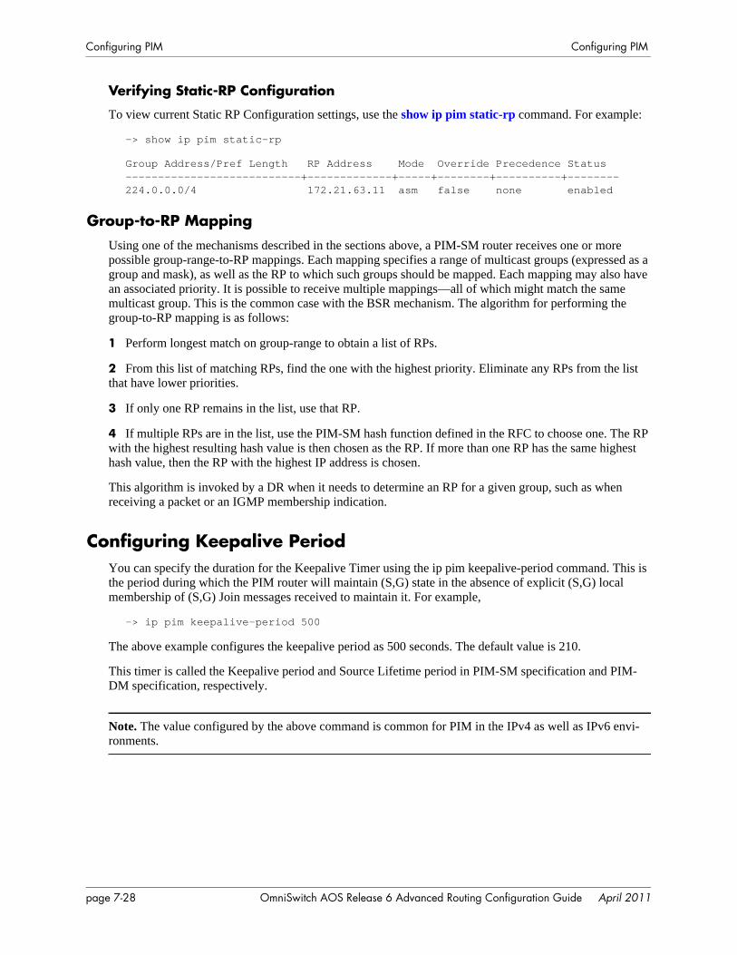
Configuring PIM Configuring PIM
Verifying Static-RP Configuration
To view current Static RP Configuration settings, use the show ip pim static-rp command. For example:
-> show ip pim static-rp
Group Address/Pref Length RP Address Mode Override Precedence Status---------------------------+-------------+-----+--------+----------+--------224.0.0.0/4 172.21.63.11 asm false none enabled
Group-to-RP MappingUsing one of the mechanisms described in the sections above, a PIM-SM router receives one or more possible group-range-to-RP mappings. Each mapping specifies a range of multicast groups (expressed as a group and mask), as well as the RP to which such groups should be mapped. Each mapping may also have an associated priority. It is possible to receive multiple mappings—all of which might match the same multicast group. This is the common case with the BSR mechanism. The algorithm for performing the group-to-RP mapping is as follows:
1 Perform longest match on group-range to obtain a list of RPs.
2 From this list of matching RPs, find the one with the highest priority. Eliminate any RPs from the list that have lower priorities.
3 If only one RP remains in the list, use that RP.
4 If multiple RPs are in the list, use the PIM-SM hash function defined in the RFC to choose one. The RP with the highest resulting hash value is then chosen as the RP. If more than one RP has the same highest hash value, then the RP with the highest IP address is chosen.
This algorithm is invoked by a DR when it needs to determine an RP for a given group, such as when receiving a packet or an IGMP membership indication.
Configuring Keepalive PeriodYou can specify the duration for the Keepalive Timer using the ip pim keepalive-period command. This is the period during which the PIM router will maintain (S,G) state in the absence of explicit (S,G) local membership of (S,G) Join messages received to maintain it. For example,
-> ip pim keepalive-period 500
The above example configures the keepalive period as 500 seconds. The default value is 210.
This timer is called the Keepalive period and Source Lifetime period in PIM-SM specification and PIM-DM specification, respectively.
Note. The value configured by the above command is common for PIM in the IPv4 as well as IPv6 envi-ronments.
page 7-28 OmniSwitch AOS Release 6 Advanced Routing Configuration Guide April 2011
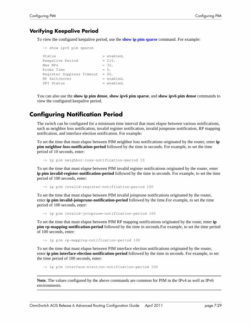
Configuring PIM Configuring PIM
Verifying Keepalive PeriodTo view the configured keepalive period, use the show ip pim sparse command. For example:
-> show ipv6 pim sparse
Status = enabled,Keepalive Period = 210,Max RPs = 32,Probe Time = 5,Register Suppress Timeout = 60,RP Switchover = enabled,SPT Status = enabled,
You can also use the show ip pim dense, show ipv6 pim sparse, and show ipv6 pim dense commands to view the configured keepalive period.
Configuring Notification PeriodThe switch can be configured for a minimum time interval that must elapse between various notifications, such as neighbor loss notification, invalid register notification, invalid joinprune notification, RP mapping notification, and interface election notification. For example:
To set the time that must elapse between PIM neighbor loss notifications originated by the router, enter ip pim neighbor-loss-notification-period followed by the time in seconds. For example, to set the time period of 10 seconds, enter:
-> ip pim neighbor-loss-notification-period 10
To set the time that must elapse between PIM invalid register notifications originated by the router, enter ip pim invalid-register-notification-period followed by the time in seconds. For example, to set the time period of 100 seconds, enter:
-> ip pim invalid-register-notification-period 100
To set the time that must elapse between PIM invalid joinprune notifications originated by the router, enter ip pim invalid-joinprune-notification-period followed by the time.For example, to set the time period of 100 seconds, enter:
-> ip pim invalid-joinprune-notification-period 100
To set the time that must elapse between PIM RP mapping notifications originated by the route, enter ip pim rp-mapping-notification-period followed by the time in seconds.For example, to set the time period of 100 seconds, enter:
-> ip pim rp-mapping-notification-period 100
To set the time that must elapse between PIM interface election notifications originated by the router, enter ip pim interface-election-notification-period followed by the time in seconds. For example, to set the time period of 100 seconds, enter:
-> ip pim interface-election-notification-period 100
Note. The values configured by the above commands are common for PIM in the IPv4 as well as IPv6 environments.
OmniSwitch AOS Release 6 Advanced Routing Configuration Guide April 2011 page 7-29
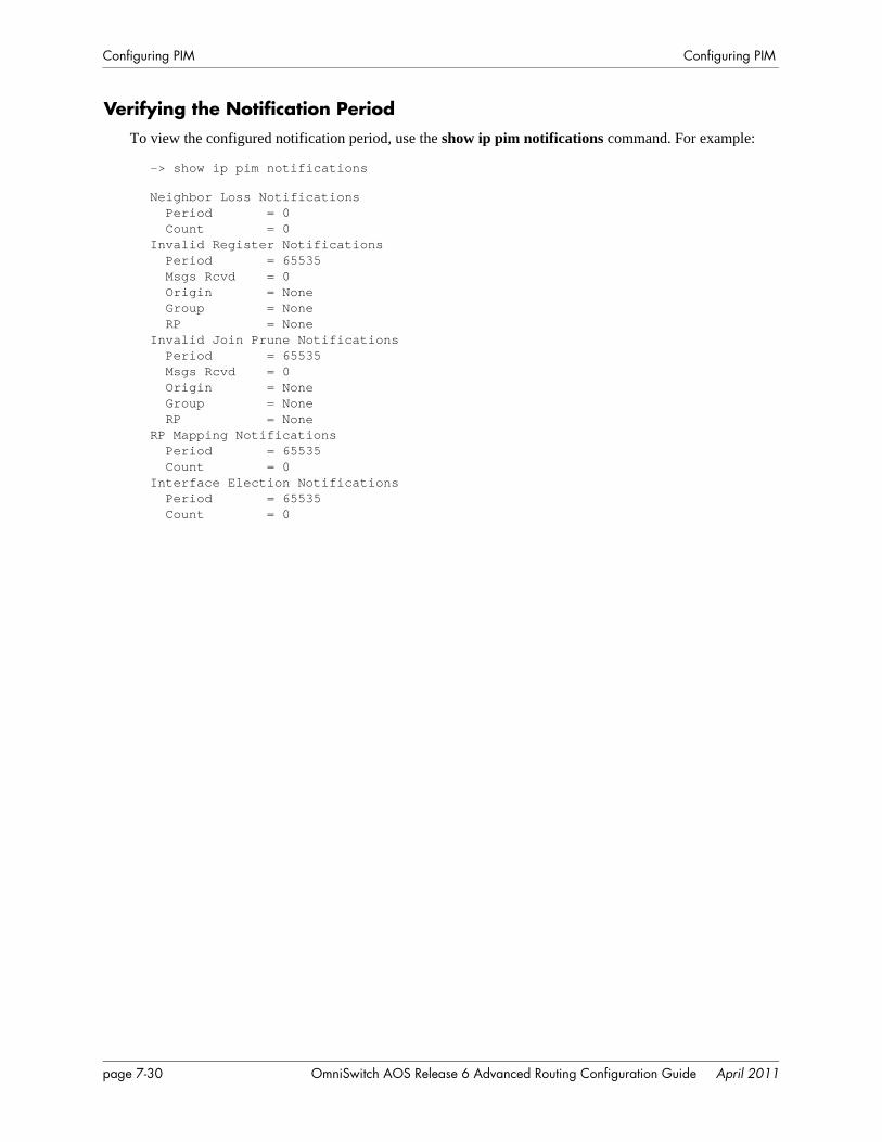
Configuring PIM Configuring PIM
Verifying the Notification PeriodTo view the configured notification period, use the show ip pim notifications command. For example:
-> show ip pim notifications
Neighbor Loss Notifications Period = 0 Count = 0Invalid Register Notifications Period = 65535 Msgs Rcvd = 0 Origin = None Group = None RP = NoneInvalid Join Prune Notifications Period = 65535 Msgs Rcvd = 0 Origin = None Group = None RP = NoneRP Mapping Notifications Period = 65535 Count = 0Interface Election Notifications Period = 65535 Count = 0
page 7-30 OmniSwitch AOS Release 6 Advanced Routing Configuration Guide April 2011
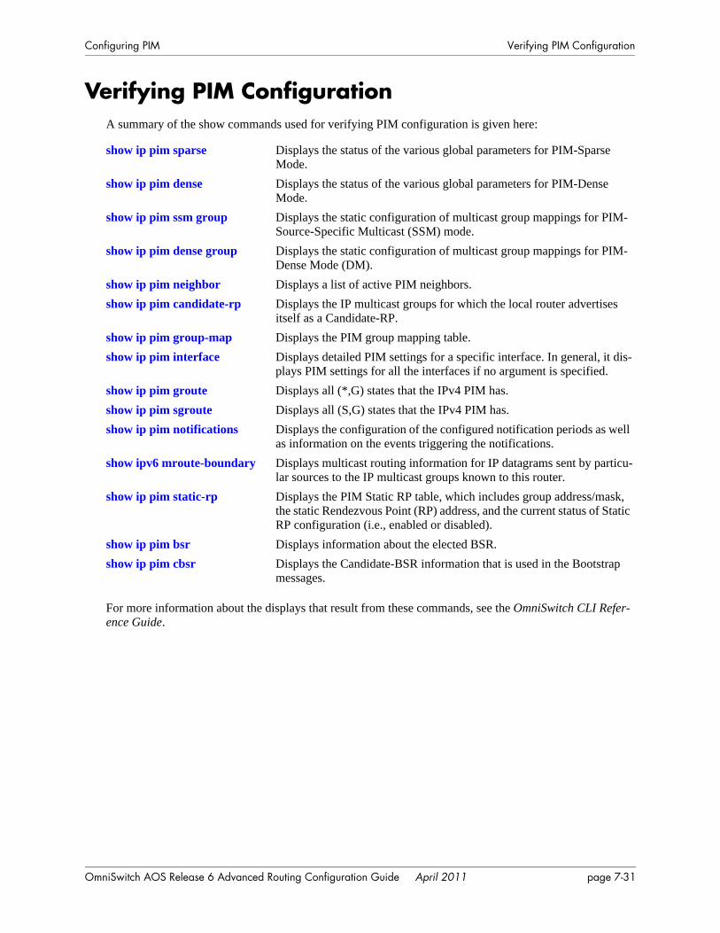
Configuring PIM Verifying PIM Configuration
Verifying PIM ConfigurationA summary of the show commands used for verifying PIM configuration is given here:
For more information about the displays that result from these commands, see the OmniSwitch CLI Refer-ence Guide.
show ip pim sparse Displays the status of the various global parameters for PIM-Sparse Mode.
show ip pim dense Displays the status of the various global parameters for PIM-Dense Mode.
show ip pim ssm group Displays the static configuration of multicast group mappings for PIM-Source-Specific Multicast (SSM) mode.
show ip pim dense group Displays the static configuration of multicast group mappings for PIM-Dense Mode (DM).
show ip pim neighbor Displays a list of active PIM neighbors.show ip pim candidate-rp Displays the IP multicast groups for which the local router advertises
itself as a Candidate-RP. show ip pim group-map Displays the PIM group mapping table.show ip pim interface Displays detailed PIM settings for a specific interface. In general, it dis-
plays PIM settings for all the interfaces if no argument is specified.show ip pim groute Displays all (*,G) states that the IPv4 PIM has.show ip pim sgroute Displays all (S,G) states that the IPv4 PIM has.show ip pim notifications Displays the configuration of the configured notification periods as well
as information on the events triggering the notifications.show ipv6 mroute-boundary Displays multicast routing information for IP datagrams sent by particu-
lar sources to the IP multicast groups known to this router.show ip pim static-rp Displays the PIM Static RP table, which includes group address/mask,
the static Rendezvous Point (RP) address, and the current status of Static RP configuration (i.e., enabled or disabled).
show ip pim bsr Displays information about the elected BSR.show ip pim cbsr Displays the Candidate-BSR information that is used in the Bootstrap
messages.
OmniSwitch AOS Release 6 Advanced Routing Configuration Guide April 2011 page 7-31
PIM for IPv6 Overview Configuring PIM
PIM for IPv6 OverviewIP version 6 (IPv6) is a new version of the Internet Protocol, designed as the successor to IP version 4 (IPv4), to overcome certain limitations in IPv4. IPv6 adds significant extra features that were not possible with IPv4. These include automatic configuration of hosts, extensive multicasting capabilities, and built-in security using authentication headers and encryption. Built-in support for QOS and path control are also features found in IPv6.
IPv6 is a hierarchical 128-bit addressing scheme that consists of 8 fields, composed of 16 bits each. An IPv6 address is written as a hexadecimal value (0-F) in groups of four, separated by colons. IPv6 provides 3x10^38 addresses, which can help overcome the shortage of IP addresses needed for Internet usage.
There are three types of IPv6 addresses: Unicast, Anycast, and Multicast. A Unicast address identifies a single interface, and a packet destined for a Unicast address is delivered to the interface identified by that address. An Anycast address identifies a set of interfaces, and a packet destined for an Anycast address is delivered to the nearest interface identified by that Anycast address. A Multicast address identifies a set of interfaces, and a packet destined for a Multicast address is delivered to all the interfaces identified by that Multicast address. There are no broadcast addresses in IPv6.
The current release also provides support for PIM to be configured in IPv6 environments using IPv6 multi-cast addresses. In the IPv6 addressing scheme, multicast addresses begin with the prefix ff00::/8. Similar to IPv6 unicast addresses, IPv6 multicast addresses also have different scopes depending on their prefix, though the range of possible scopes is different.
Multicast Listener Discovery (MLD) is the protocol used by an IPv6 router to discover the nodes that request multicast packets on its directly attached links and the multicast addresses that are of interest to those neighboring nodes. MLD is derived from version 2 of IPv4's Internet Group Management Protocol, IGMPv2. MLD uses ICMPv6 message types, rather than IGMP message types.
IPv6 PIM-SSM SupportIPv6 Protocol-Independent Multicast Source-Specific Multicast (IPv6 PIM-SSM) is a highly efficient extension of IPv6 PIM. SSM, using an explicit channel subscription model, allows receivers to receive multicast traffic directly from the source; an RP tree model is not used. In other words, a Shortest Path Tree (SPT) between the receiver and the source is created without the use of a Rendezvous Point (RP).
By default, IPv6 PIM software supports Source-Specific Multicast. No additional user configuration is required. IPv6 PIM-SSM is automatically enabled and operational as long as IPv6 PIM is loaded (see page 7-6) and IGMPv3 source-specific joins are received within the SSM address range.
Source-Specific Multicast AddressesThe multicast addresses range FF3x::/32 that has been reserved by the Internet Assigned Numbers Author-ity (IANA) as Source-Specific Multicast (SSM) destination addresses is not enabled automatically and must be configured manually to support SSM. Addresses within this range are reserved for use by source-specific applications and protocols (e.g., IPv6 PIM-SSM) and cannot be used for any other functions or protocols. However, you can also map additional multicast address ranges for the SSM group.
page 7-32 OmniSwitch AOS Release 6 Advanced Routing Configuration Guide April 2011
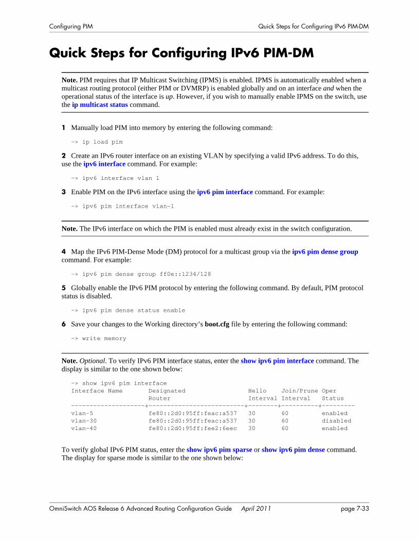
Configuring PIM Quick Steps for Configuring IPv6 PIM-DM
Quick Steps for Configuring IPv6 PIM-DM
Note. PIM requires that IP Multicast Switching (IPMS) is enabled. IPMS is automatically enabled when a multicast routing protocol (either PIM or DVMRP) is enabled globally and on an interface and when the operational status of the interface is up. However, if you wish to manually enable IPMS on the switch, use the ip multicast status command.
1 Manually load PIM into memory by entering the following command:
-> ip load pim
2 Create an IPv6 router interface on an existing VLAN by specifying a valid IPv6 address. To do this, use the ipv6 interface command. For example:
-> ipv6 interface vlan 1
3 Enable PIM on the IPv6 interface using the ipv6 pim interface command. For example:
-> ipv6 pim interface vlan-1
Note. The IPv6 interface on which the PIM is enabled must already exist in the switch configuration.
4 Map the IPv6 PIM-Dense Mode (DM) protocol for a multicast group via the ipv6 pim dense group command. For example:
-> ipv6 pim dense group ff0e::1234/128
5 Globally enable the IPv6 PIM protocol by entering the following command. By default, PIM protocol status is disabled.
-> ipv6 pim dense status enable
6 Save your changes to the Working directory’s boot.cfg file by entering the following command:
-> write memory
Note. Optional. To verify IPv6 PIM interface status, enter the show ipv6 pim interface command. The display is similar to the one shown below:
-> show ipv6 pim interfaceInterface Name Designated Hello Join/Prune Oper Router Interval Interval Status--------------------+--------------------------+--------+----------+---------vlan-5 fe80::2d0:95ff:feac:a537 30 60 enabled vlan-30 fe80::2d0:95ff:feac:a537 30 60 disabled vlan-40 fe80::2d0:95ff:fee2:6eec 30 60 enabled
To verify global IPv6 PIM status, enter the show ipv6 pim sparse or show ipv6 pim dense command. The display for sparse mode is similar to the one shown below:
OmniSwitch AOS Release 6 Advanced Routing Configuration Guide April 2011 page 7-33
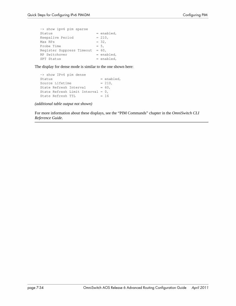
Quick Steps for Configuring IPv6 PIM-DM Configuring PIM
-> show ipv6 pim sparseStatus = enabled,Keepalive Period = 210,Max RPs = 32,Probe Time = 5,Register Suppress Timeout = 60,RP Switchover = enabled,SPT Status = enabled,
The display for dense mode is similar to the one shown here:
-> show IPv6 pim denseStatus = enabled,Source Lifetime = 210,State Refresh Interval = 60,State Refresh Limit Interval = 0,State Refresh TTL = 16
(additional table output not shown)
For more information about these displays, see the “PIM Commands” chapter in the OmniSwitch CLI Reference Guide.
page 7-34 OmniSwitch AOS Release 6 Advanced Routing Configuration Guide April 2011
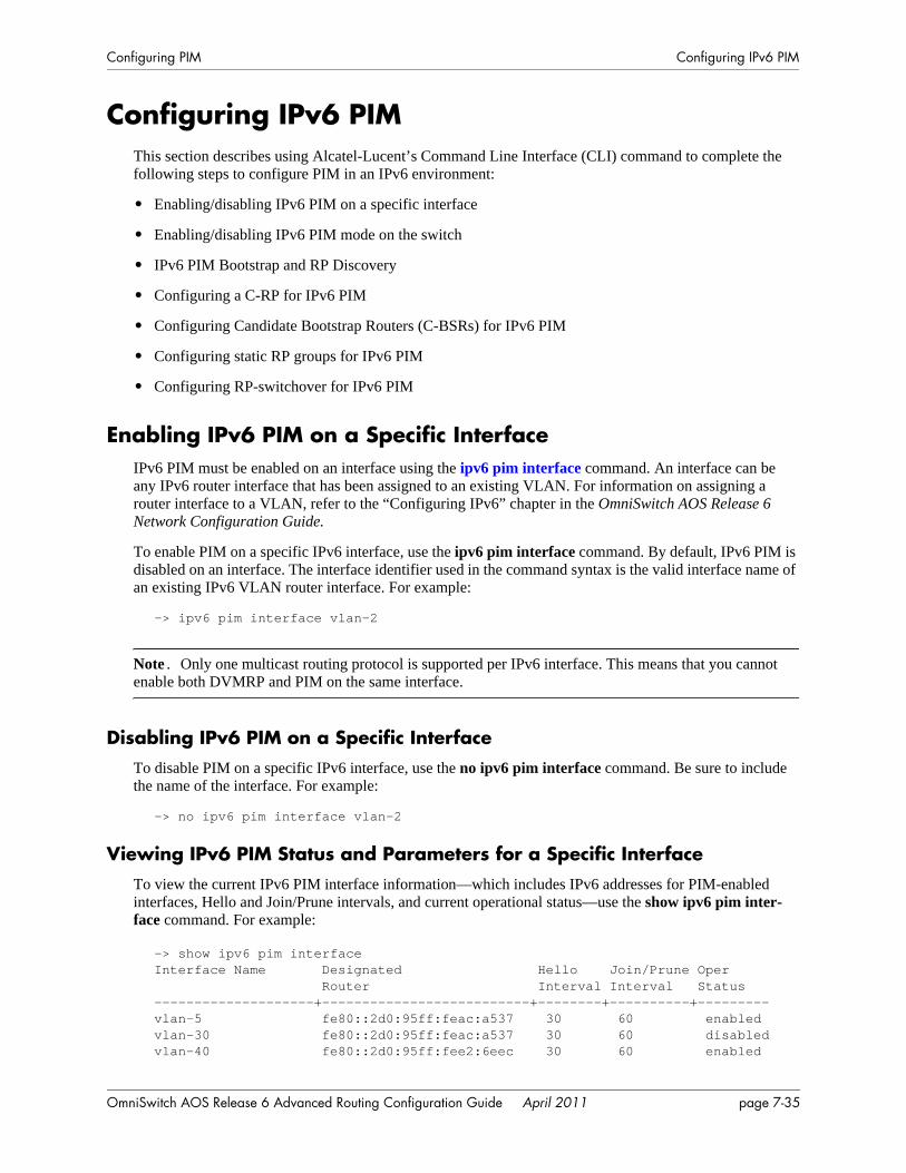
Configuring PIM Configuring IPv6 PIM
Configuring IPv6 PIMThis section describes using Alcatel-Lucent’s Command Line Interface (CLI) command to complete the following steps to configure PIM in an IPv6 environment:
• Enabling/disabling IPv6 PIM on a specific interface
• Enabling/disabling IPv6 PIM mode on the switch
• IPv6 PIM Bootstrap and RP Discovery
• Configuring a C-RP for IPv6 PIM
• Configuring Candidate Bootstrap Routers (C-BSRs) for IPv6 PIM
• Configuring static RP groups for IPv6 PIM
• Configuring RP-switchover for IPv6 PIM
Enabling IPv6 PIM on a Specific InterfaceIPv6 PIM must be enabled on an interface using the ipv6 pim interface command. An interface can be any IPv6 router interface that has been assigned to an existing VLAN. For information on assigning a router interface to a VLAN, refer to the “Configuring IPv6” chapter in the OmniSwitch AOS Release 6 Network Configuration Guide.
To enable PIM on a specific IPv6 interface, use the ipv6 pim interface command. By default, IPv6 PIM is disabled on an interface. The interface identifier used in the command syntax is the valid interface name of an existing IPv6 VLAN router interface. For example:
-> ipv6 pim interface vlan-2
Note. Only one multicast routing protocol is supported per IPv6 interface. This means that you cannot enable both DVMRP and PIM on the same interface.
Disabling IPv6 PIM on a Specific InterfaceTo disable PIM on a specific IPv6 interface, use the no ipv6 pim interface command. Be sure to include the name of the interface. For example:
-> no ipv6 pim interface vlan-2
Viewing IPv6 PIM Status and Parameters for a Specific InterfaceTo view the current IPv6 PIM interface information—which includes IPv6 addresses for PIM-enabled interfaces, Hello and Join/Prune intervals, and current operational status—use the show ipv6 pim inter-face command. For example:
-> show ipv6 pim interfaceInterface Name Designated Hello Join/Prune Oper Router Interval Interval Status--------------------+--------------------------+--------+----------+---------vlan-5 fe80::2d0:95ff:feac:a537 30 60 enabled vlan-30 fe80::2d0:95ff:feac:a537 30 60 disabledvlan-40 fe80::2d0:95ff:fee2:6eec 30 60 enabled
OmniSwitch AOS Release 6 Advanced Routing Configuration Guide April 2011 page 7-35
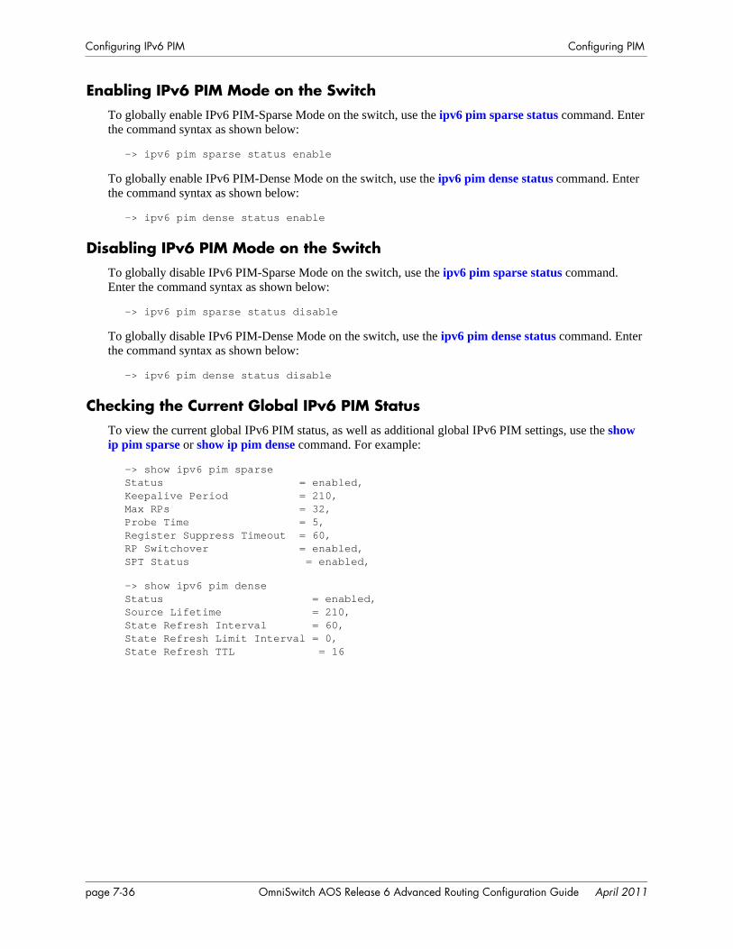
Configuring IPv6 PIM Configuring PIM
Enabling IPv6 PIM Mode on the SwitchTo globally enable IPv6 PIM-Sparse Mode on the switch, use the ipv6 pim sparse status command. Enter the command syntax as shown below:
-> ipv6 pim sparse status enable
To globally enable IPv6 PIM-Dense Mode on the switch, use the ipv6 pim dense status command. Enter the command syntax as shown below:
-> ipv6 pim dense status enable
Disabling IPv6 PIM Mode on the SwitchTo globally disable IPv6 PIM-Sparse Mode on the switch, use the ipv6 pim sparse status command. Enter the command syntax as shown below:
-> ipv6 pim sparse status disable
To globally disable IPv6 PIM-Dense Mode on the switch, use the ipv6 pim dense status command. Enter the command syntax as shown below:
-> ipv6 pim dense status disable
Checking the Current Global IPv6 PIM StatusTo view the current global IPv6 PIM status, as well as additional global IPv6 PIM settings, use the show ip pim sparse or show ip pim dense command. For example:
-> show ipv6 pim sparseStatus = enabled,Keepalive Period = 210,Max RPs = 32,Probe Time = 5,Register Suppress Timeout = 60,RP Switchover = enabled,SPT Status = enabled,
-> show ipv6 pim denseStatus = enabled, Source Lifetime = 210,State Refresh Interval = 60,State Refresh Limit Interval = 0,State Refresh TTL = 16
page 7-36 OmniSwitch AOS Release 6 Advanced Routing Configuration Guide April 2011
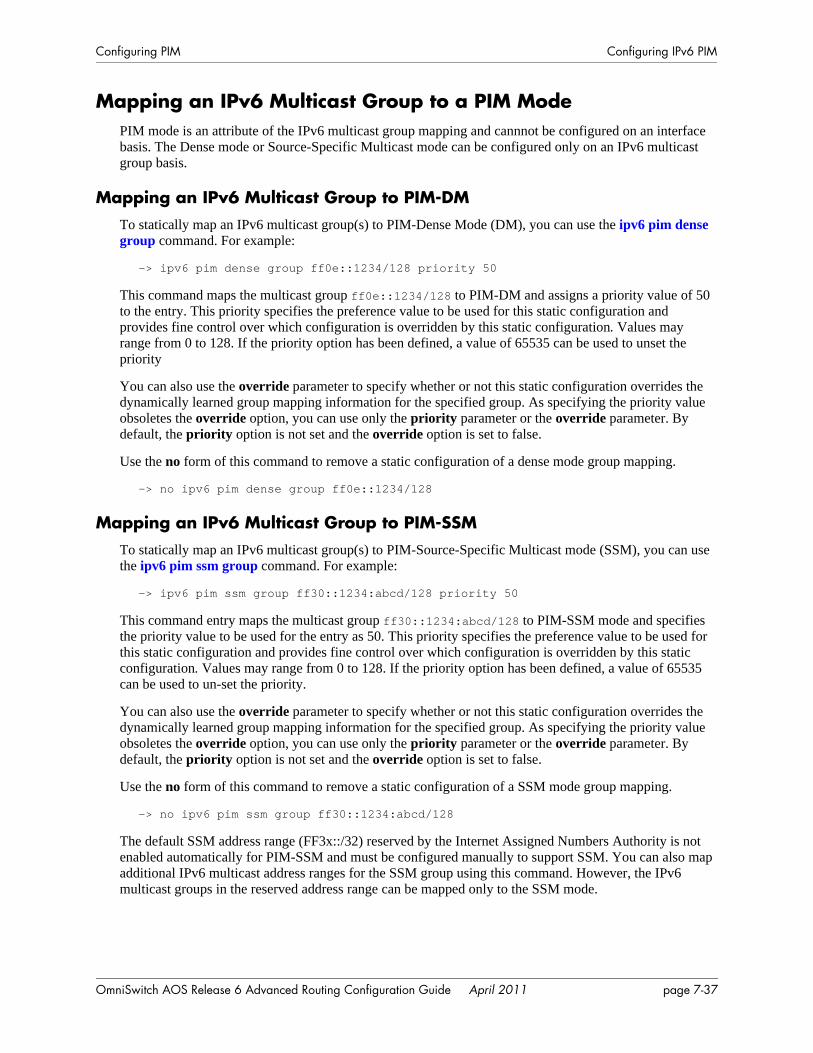
Configuring PIM Configuring IPv6 PIM
Mapping an IPv6 Multicast Group to a PIM ModePIM mode is an attribute of the IPv6 multicast group mapping and cannnot be configured on an interface basis. The Dense mode or Source-Specific Multicast mode can be configured only on an IPv6 multicast group basis.
Mapping an IPv6 Multicast Group to PIM-DMTo statically map an IPv6 multicast group(s) to PIM-Dense Mode (DM), you can use the ipv6 pim dense group command. For example:
-> ipv6 pim dense group ff0e::1234/128 priority 50
This command maps the multicast group ff0e::1234/128 to PIM-DM and assigns a priority value of 50 to the entry. This priority specifies the preference value to be used for this static configuration and provides fine control over which configuration is overridden by this static configuration. Values may range from 0 to 128. If the priority option has been defined, a value of 65535 can be used to unset the priority
You can also use the override parameter to specify whether or not this static configuration overrides the dynamically learned group mapping information for the specified group. As specifying the priority value obsoletes the override option, you can use only the priority parameter or the override parameter. By default, the priority option is not set and the override option is set to false.
Use the no form of this command to remove a static configuration of a dense mode group mapping.
-> no ipv6 pim dense group ff0e::1234/128
Mapping an IPv6 Multicast Group to PIM-SSMTo statically map an IPv6 multicast group(s) to PIM-Source-Specific Multicast mode (SSM), you can use the ipv6 pim ssm group command. For example:
-> ipv6 pim ssm group ff30::1234:abcd/128 priority 50
This command entry maps the multicast group ff30::1234:abcd/128 to PIM-SSM mode and specifies the priority value to be used for the entry as 50. This priority specifies the preference value to be used for this static configuration and provides fine control over which configuration is overridden by this static configuration. Values may range from 0 to 128. If the priority option has been defined, a value of 65535 can be used to un-set the priority.
You can also use the override parameter to specify whether or not this static configuration overrides the dynamically learned group mapping information for the specified group. As specifying the priority value obsoletes the override option, you can use only the priority parameter or the override parameter. By default, the priority option is not set and the override option is set to false.
Use the no form of this command to remove a static configuration of a SSM mode group mapping.
-> no ipv6 pim ssm group ff30::1234:abcd/128
The default SSM address range (FF3x::/32) reserved by the Internet Assigned Numbers Authority is not enabled automatically for PIM-SSM and must be configured manually to support SSM. You can also map additional IPv6 multicast address ranges for the SSM group using this command. However, the IPv6 multicast groups in the reserved address range can be mapped only to the SSM mode.
OmniSwitch AOS Release 6 Advanced Routing Configuration Guide April 2011 page 7-37
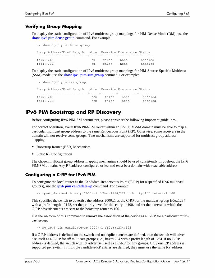
Configuring IPv6 PIM Configuring PIM
Verifying Group MappingTo display the static configuration of IPv6 multicast group mappings for PIM-Dense Mode (DM), use the show ipv6 pim dense group command. For example:
-> show ipv6 pim dense group
Group Address/Pref Length Mode Override Precedence Status---------------------------+-----+--------+----------+--------ff00::/8 dm false none enabledff34::/32 dm false none enabled
To display the static configuration of IPv6 multicast group mappings for PIM-Source-Specific Multicast (SSM) mode, use the show ipv6 pim ssm group commad. For example:
-> show ipv6 pim ssm group
Group Address/Pref Length Mode Override Precedence Status---------------------------+-----+--------+----------+--------ff00::/8 ssm false none enabledff34::/32 ssm false none enabled
IPv6 PIM Bootstrap and RP DiscoveryBefore configuring IPv6 PIM-SM parameters, please consider the following important guidelines.
For correct operation, every IPv6 PIM-SM router within an IPv6 PIM-SM domain must be able to map a particular multicast group address to the same Rendezvous Point (RP). Otherwise, some receivers in the domain will not receive some groups. Two mechanisms are supported for multicast group address mapping:
• Bootstrap Router (BSR) Mechanism
• Static RP Configuration
The chosen multicast group address mapping mechanism should be used consistently throughout the IPv6 PIM-SM domain. Any RP address configured or learned must be a domain-wide reachable address.
Configuring a C-RP for IPv6 PIMTo configure the local router as the Candidate-Rendezvous Point (C-RP) for a specified IPv6 multicast group(s), use the ipv6 pim candidate-rp command. For example:
-> ipv6 pim candidate-rp 2000::1 ff0e::1234/128 priority 100 interval 100
This specifies the switch to advertise the address 2000::1 as the C-RP for the multicast group ff0e::1234 with a prefix length of 128, set the priority level for this entry to 100, and set the interval at which the C-RP advertisements are sent to the bootstrap router to 100.
Use the no form of this command to remove the association of the device as a C-RP for a particular multi-cast group.
-> no ipv6 pim candidate-rp 2000::1 ff0e::1234/128
If a C-RP address is defined on the switch and no explicit entries are defined, then the switch will adver-tise itself as a C-RP for all multicast groups (i.e., ff0e::1234 with a prefix length of 128). If no C-RP address is defined, the switch will not advertise itself as a C-RP for any groups. Only one RP address is supported per switch. If multiple candidate-RP entries are defined, they must use the same RP address.
page 7-38 OmniSwitch AOS Release 6 Advanced Routing Configuration Guide April 2011
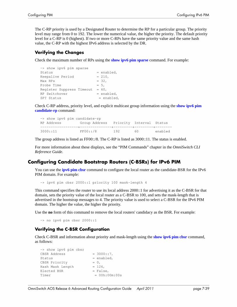
Configuring PIM Configuring IPv6 PIM
The C-RP priority is used by a Designated Router to determine the RP for a particular group. The priority level may range from 0 to 192. The lower the numerical value, the higher the priority. The default priority level for a C-RP is 0 (highest). If two or more C-RPs have the same priority value and the same hash value, the C-RP with the highest IPv6 address is selected by the DR.
Verifying the Changes
Check the maximum number of RPs using the show ipv6 pim sparse command. For example:
-> show ipv6 pim sparseStatus = enabled,Keepalive Period = 210,Max RPs = 32,Probe Time = 5,Register Suppress Timeout = 60,RP Switchover = enabled,SPT Status = enabled,
Check C-RP address, priority level, and explicit multicast group information using the show ipv6 pim candidate-rp command:
-> show ipv6 pim candidate-rpRP Address Group Address Priority Interval Status------------------+---------------+---------+---------+--------3000::11 FF00::/8 192 60 enabled
The group address is listed as FF00::/8. The C-RP is listed as 3000::11. The status is enabled.
For more information about these displays, see the “PIM Commands” chapter in the OmniSwitch CLI Reference Guide.
Configuring Candidate Bootstrap Routers (C-BSRs) for IPv6 PIMYou can use the ipv6 pim cbsr command to configure the local router as the candidate-BSR for the IPv6 PIM domain. For example:
-> ipv6 pim cbsr 2000::1 priority 100 mask-length 4
This command specifies the router to use its local address 2000::1 for advertising it as the C-BSR for that domain, sets the priority value of the local router as a C-BSR to 100, and sets the mask-length that is advertised in the bootstrap messages to 4. The priority value is used to select a C-BSR for the IPv6 PIM domain. The higher the value, the higher the priority.
Use the no form of this command to remove the local routers' candidacy as the BSR. For example:
-> no ipv6 pim cbsr 2000::1
Verifying the C-BSR Configuration
Check C-BSR and information about priority and mask-length using the show ipv6 pim cbsr command, as follows:
-> show ipv6 pim cbsrCBSR Address = 3000::7,Status = enabled,CBSR Priority = 0,Hash Mask Length = 126,Elected BSR = False,Timer = 00h:00m:00s
OmniSwitch AOS Release 6 Advanced Routing Configuration Guide April 2011 page 7-39
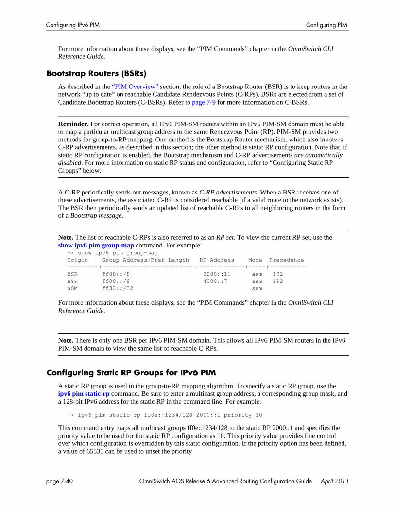
Configuring IPv6 PIM Configuring PIM
For more information about these displays, see the “PIM Commands” chapter in the OmniSwitch CLI Reference Guide.
Bootstrap Routers (BSRs)As described in the “PIM Overview” section, the role of a Bootstrap Router (BSR) is to keep routers in the network “up to date” on reachable Candidate Rendezvous Points (C-RPs). BSRs are elected from a set of Candidate Bootstrap Routers (C-BSRs). Refer to page 7-9 for more information on C-BSRs.
Reminder. For correct operation, all IPv6 PIM-SM routers within an IPv6 PIM-SM domain must be able to map a particular multicast group address to the same Rendezvous Point (RP). PIM-SM provides two methods for group-to-RP mapping. One method is the Bootstrap Router mechanism, which also involves C-RP advertisements, as described in this section; the other method is static RP configuration. Note that, if static RP configuration is enabled, the Bootstrap mechanism and C-RP advertisements are automatically disabled. For more information on static RP status and configuration, refer to “Configuring Static RP Groups” below.
A C-RP periodically sends out messages, known as C-RP advertisements. When a BSR receives one of these advertisements, the associated C-RP is considered reachable (if a valid route to the network exists). The BSR then periodically sends an updated list of reachable C-RPs to all neighboring routers in the form of a Bootstrap message.
Note. The list of reachable C-RPs is also referred to as an RP set. To view the current RP set, use the show ipv6 pim group-map command. For example:
-> show ipv6 pim group-mapOrigin Group Address/Pref Length RP Address Mode Precedence ---------+---------------------------+-------------+-----+-----------BSR ff00::/8 3000::11 asm 192BSR ff00::/8 4000::7 asm 192SSM ff33::/32 ssm
For more information about these displays, see the “PIM Commands” chapter in the OmniSwitch CLI Reference Guide.
Note. There is only one BSR per IPv6 PIM-SM domain. This allows all IPv6 PIM-SM routers in the IPv6 PIM-SM domain to view the same list of reachable C-RPs.
Configuring Static RP Groups for IPv6 PIMA static RP group is used in the group-to-RP mapping algorithm. To specify a static RP group, use the ipv6 pim static-rp command. Be sure to enter a multicast group address, a corresponding group mask, and a 128-bit IPv6 address for the static RP in the command line. For example:
-> ipv6 pim static-rp ff0e::1234/128 2000::1 priority 10
This command entry maps all multicast groups ff0e::1234/128 to the static RP 2000::1 and specifies the priority value to be used for the static RP configuration as 10. This priority value provides fine control over which configuration is overridden by this static configuration. If the priority option has been defined, a value of 65535 can be used to unset the priority
page 7-40 OmniSwitch AOS Release 6 Advanced Routing Configuration Guide April 2011
Configuring PIM Configuring IPv6 PIM
You can also specify whether or not this static RP configuration to override the dynamically learned RP information for the specified group using the override parameter. As specifying the priority value obso-letes the override option, you can use either the priority or override parameter only.
Use the no form of this command to delete a static RP configuration.
-> no ipv6 pim static-rp ff0e::1234/128 2000::1
The IPv6 PIM-Source-Specific Multicast (SSM) mode for the default SSM address range (FF3x::/32) reserved by the Internet Assigned Numbers Authority is not enabled automatically and must be config-ured manually to support SSM. You can also map additional IPv6 multicast address ranges for the SSM group. However, the IPv6 multicast groups in the reserved address range can be mapped only to the SSM mode.
Note. If static RP status is specified, the method for group-to-RP mapping provided by the Bootstrap mechanism and C-RP advertisements is automatically disabled. For more information on this alternate method of group-to-RP mapping, refer to page 7-26.
To view current Static RP Configuration settings, use the show ipv6 pim static-rp command.
Group-to-RP MappingUsing one of the mechanisms described in the sections above, an IPv6 PIM-SM router receives one or more possible group-range-to-RP mappings. Each mapping specifies a range of IPv6 multicast groups (expressed as a group and mask), as well as the RP to which such groups should be mapped. Each mapping may also have an associated priority. It is possible to receive multiple mappings—all of which might match the same multicast group. This is the common case with the BSR mechanism. The algorithm for performing the group-to-RP mapping is as follows:
1 Perform longest match on group-range to obtain a list of RPs.
2 From this list of matching RPs, find the one with the highest priority. Eliminate any RPs from the list that have lower priorities.
3 If only one RP remains in the list, use that RP.
4 If multiple RPs are in the list, use the PIM-SM hash function defined in the RFC to choose one. The RP with the highest resulting hash value is then chosen as the RP. If more than one RP has the same high-est hash value, then the RP with the highest IPv6 address is chosen.
This algorithm is invoked by a DR when it needs to determine an RP for a given group, such as when receiving a packet or an IGMP membership indication.
OmniSwitch AOS Release 6 Advanced Routing Configuration Guide April 2011 page 7-41
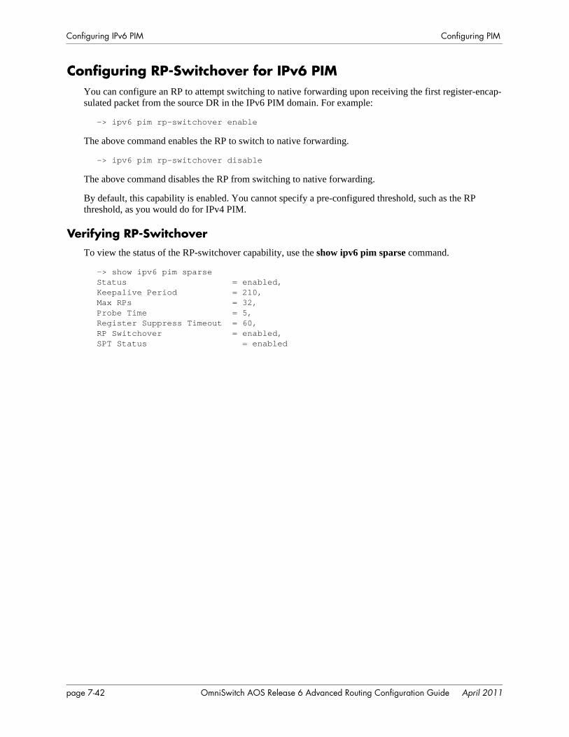
Configuring IPv6 PIM Configuring PIM
Configuring RP-Switchover for IPv6 PIMYou can configure an RP to attempt switching to native forwarding upon receiving the first register-encap-sulated packet from the source DR in the IPv6 PIM domain. For example:
-> ipv6 pim rp-switchover enable
The above command enables the RP to switch to native forwarding.
-> ipv6 pim rp-switchover disable
The above command disables the RP from switching to native forwarding.
By default, this capability is enabled. You cannot specify a pre-configured threshold, such as the RP threshold, as you would do for IPv4 PIM.
Verifying RP-SwitchoverTo view the status of the RP-switchover capability, use the show ipv6 pim sparse command.
-> show ipv6 pim sparseStatus = enabled,Keepalive Period = 210,Max RPs = 32,Probe Time = 5,Register Suppress Timeout = 60,RP Switchover = enabled,SPT Status = enabled
page 7-42 OmniSwitch AOS Release 6 Advanced Routing Configuration Guide April 2011

Configuring PIM Verifying IPv6 PIM Configuration
Verifying IPv6 PIM ConfigurationA summary of the show commands used for verifying PIM configuration is given here:
For more information about the displays that result from these commands, see the OmniSwitch CLI Refer-ence Guide.
show ipv6 pim sparse Displays the status of the various global parameters for the IPv6 PIM-Sparse Mode.
show ipv6 pim dense Displays the status of the various global parameters for the IPv6 PIM-Dense Mode.
show ipv6 pim ssm group Displays the static configuration of IPv6 multicast group mappings for PIM-Source-Specific Multicast (SSM).
show ipv6 pim dense group Displays the static configuration of IPv6 multicast group mappings for PIM-Dense Mode (DM).
show ipv6 pim neighbor Displays a list of active IPv6 PIM neighbors.show ipv6 pim candidate-rp Displays the IPv6 multicast groups for which the local router advertises
itself as a Candidate-RP.show ipv6 pim group-map Displays the IPv6 PIM group mapping table.show ipv6 pim interface Displays detailed IPv6 PIM settings for a specific interface. In general,
it displays IPv6 PIM settings for all the interfaces if no argument is specified.
show ipv6 pim groute Displays all (*,G) states that IPv6 PIM has.show ipv6 pim sgroute Displays all (S,G) states that IPv6 PIM has.show ip pim notifications Displays the configuration of the configured notification periods as well
as information on the events triggering the notifications.show ipv6 mroute Displays multicast routing information for IPv6 datagrams sent by par-
ticular sources to the IPv6 multicast groups known to this router.show ipv6 pim static-rp Displays the IPv6 PIM Static RP table, which includes IPv6 multicast
group address/prefix length, the static Rendezvous Point (RP) address, and the current status of the static RP configuration (i.e., enabled or dis-abled).
show ipv6 pim bsr Displays information about the elected IPv6 BSR.show ipv6 pim cbsr Displays the IPv6 Candidate-BSR information that is used in the Boot-
strap messages.
OmniSwitch AOS Release 6 Advanced Routing Configuration Guide April 2011 page 7-43

Verifying IPv6 PIM Configuration Configuring PIM
page 7-44 OmniSwitch AOS Release 6 Advanced Routing Configuration Guide April 2011

A Software License andCopyright Statements
This appendix contains Alcatel-Lucent and third-party software vendor license and copyright statements.
Alcatel-Lucent License Agreement
ALCATEL-LUCENT SOFTWARE LICENSE AGREEMENT
IMPORTANT. Please read the terms and conditions of this license agreement carefully before opening this package.
By opening this package, you accept and agree to the terms of this license agreement. If you are not willing to be bound by the terms of this license agreement, do not open this package. Please promptly return the product and any materials in unopened form to the place where you obtained it for a full refund.
1. License Grant. This is a license, not a sales agreement, between you (the “Licensee”) and Alcatel-Lucent. Alcatel-Lucent hereby grants to Licensee, and Licensee accepts, a non-exclusive license to use program media and computer software contained therein (the “Licensed Files”) and the accompanying user documentation (collectively the “Licensed Materials”), only as authorized in this License Agreement. Licensee, subject to the terms of this License Agreement, may use one copy of the Licensed Files on the Licensee’s system. Licensee agrees not to assign, sublicense, transfer, pledge, lease, rent, or share their rights under this License Agreement. Licensee may retain the program media for backup purposes with retention of the copyright and other proprietary notices. Except as authorized under this paragraph, no copies of the Licensed Materials or any portions thereof may be made by Licensee and Licensee shall not modify, decompile, disassemble, reverse engineer, or otherwise attempt to derive the Source Code. Licensee is also advised that Alcatel-Lucent products contain embedded software known as firmware which resides in silicon. Licensee may not copy the firmware or transfer the firmware to another medium.
2. Alcatel-Lucent’s Rights. Licensee acknowledges and agrees that the Licensed Materials are the sole property of Alcatel-Lucent and its licensors (herein “its licensors”), protected by U.S. copyright law, trade-mark law, and are licensed on a right to use basis. Licensee further acknowledges and agrees that all rights, title, and interest in and to the Licensed Materials are and shall remain with Alcatel-Lucent and its licen-sors and that no such right, license, or interest shall be asserted with respect to such copyrights and trade-marks. This License Agreement does not convey to Licensee an interest in or to the Licensed Materials, but only a limited right to use revocable in accordance with the terms of this License Agreement.
OmniSwitch AOS Release 6 Advanced Routing Configuration Guide April 2011 page A-1
Alcatel-Lucent License Agreement Software License and Copyright Statements
3. Confidentiality. Alcatel-Lucent considers the Licensed Files to contain valuable trade secrets of Alca-tel-Lucent, the unauthorized disclosure of which could cause irreparable harm to Alcatel-Lucent. Except as expressly set forth herein, Licensee agrees to use reasonable efforts not to disclose the Licensed Files to any third party and not to use the Licensed Files other than for the purpose authorized by this License Agreement. This confidentiality obligation shall continue after any termination of this License Agreement.
4. Indemnity. Licensee agrees to indemnify, defend and hold Alcatel-Lucent harmless from any claim, lawsuit, legal proceeding, settlement or judgment (including without limitation Alcatel-Lucent’s reason-able United States and local attorneys’ and expert witnesses’ fees and costs) arising out of or in connec-tion with the unauthorized copying, marketing, performance or distribution of the Licensed Files.
5. Limited Warranty. Alcatel-Lucent warrants, for Licensee’s benefit alone, that the program media shall, for a period of ninety (90) days from the date of commencement of this License Agreement (referred to as the Warranty Period), be free from defects in material and workmanship. Alcatel-Lucent further warrants, for Licensee benefit alone, that during the Warranty Period the Licensed Files shall operate substantially in accordance with the functional specifications in the User Guide. If during the Warranty Period, a defect in the Licensed Files appears, Licensee may return the Licensed Files to Alcatel-Lucent for either replacement or, if so elected by Alcatel-Lucent, refund of amounts paid by Licensee under this License Agreement. EXCEPT FOR THE WARRANTIES SET FORTH ABOVE, THE LICENSED MATERIALS ARE LICENSED “AS IS” AND ALCATEL-LUCENT AND ITS LICENSORS DISCLAIM ANY AND ALL OTHER WARRANTIES, WHETHER EXPRESS OR IMPLIED, INCLUD-ING (WITHOUT LIMITATION) ANY IMPLIED WARRANTIES OF MERCHANTABILITY OR FITNESS FOR A PARTICULAR PURPOSE. SOME STATES DO NOT ALLOW THE EXCLUSION OF IMPLIED WARRANTIES SO THE ABOVE EXCLUSIONS MAY NOT APPLY TO LICENSEE. THIS WARRANTY GIVES THE LICENSEE SPECIFIC LEGAL RIGHTS. LICENSEE MAY ALSO HAVE OTHER RIGHTS WHICH VARY FROM STATE TO STATE.
6. Limitation of Liability. Alcatel-Lucent’s cumulative liability to Licensee or any other party for any loss or damages resulting from any claims, demands, or actions arising out of or relating to this License Agreement shall not exceed the license fee paid to Alcatel-Lucent for the Licensed Materials. IN NO EVENT SHALL ALCATEL-LUCENT BE LIABLE FOR ANY INDIRECT, INCIDENTAL, CONSE-QUENTIAL, SPECIAL, OR EXEMPLARY DAMAGES OR LOST PROFITS, EVEN IF ALCATEL-LUCENT HAS BEEN ADVISED OF THE POSSIBILITY OF SUCH DAMAGES. SOME STATES DO NOT ALLOW THE LIMITATION OR EXCLUSION OF LIABILITY FOR INCIDENTAL OR CONSE-QUENTIAL DAMAGES, SO THE ABOVE LIMITATION OR EXCLUSION TO INCIDENTAL OR CONSEQUENTIAL DAMAGES MAY NOT APPLY TO LICENSEE.
7. Export Control. This product is subject to the jurisdiction of the United States. Licensee may not export or reexport the Licensed Files, without complying with all United States export laws and regula-tions, including but not limited to (i) obtaining prior authorization from the U.S. Department of Commerce if a validated export license is required, and (ii) obtaining “written assurances” from licensees, if required.
8. Support and Maintenance. Except as may be provided in a separate agreement between Alcatel-Lucent and Licensee, if any, Alcatel-Lucent is under no obligation to maintain or support the copies of the Licensed Files made and distributed hereunder and Alcatel-Lucent has no obligation to furnish Licensee with any further assistance, documentation or information of any nature or kind.
9. Term. This License Agreement is effective upon Licensee opening this package and shall continue until terminated. Licensee may terminate this License Agreement at any time by returning the Licensed Materi-als and all copies thereof and extracts therefrom to Alcatel-Lucent and certifying to Alcatel-Lucent in writ-ing that all Licensed Materials and all copies thereof and extracts therefrom have been returned or erased by the memory of Licensee’s computer or made non-readable. Alcatel-Lucent may terminate this License Agreement upon the breach by Licensee of any term hereof. Upon such termination by Alcatel-Lucent, Licensee agrees to return to Alcatel-Lucent or destroy the Licensed Materials and all copies and portions thereof.
page A-2 OmniSwitch AOS Release 6 Advanced Routing Configuration Guide April 2011

Software License and Copyright Statements Alcatel-Lucent License Agreement
10. Governing Law. This License Agreement shall be construed and governed in accordance with the laws of the State of California.
11. Severability. Should any term of this License Agreement be declared void or unenforceable by any court of competent jurisdiction, such declaration shall have no effect on the remaining terms herein.
12. No Waiver. The failure of either party to enforce any rights granted hereunder or to take action against the other party in the event of any breach hereunder shall not be deemed a waiver by that party as to subsequent enforcement of rights or subsequent actions in the event of future breaches.
13. Notes to United States Government Users. Software and documentation are provided with restricted rights. Use, duplication or disclosure by the government is subject to (i) restrictions set forth in GSA ADP Schedule Contract with Alcatel-Lucent’s reseller(s), or (ii) restrictions set forth in subparagraph (c) (1) and (2) of 48 CFR 52.227-19, as applicable.
14.Third Party Materials. Licensee is notified that the Licensed Files contain third party software and materials licensed to Alcatel-Lucent by certain third party licensors. Some third party licensors (e.g., Wind River and their licensors with respect to the Run-Time Module) are third part beneficiaries to this License Agreement with full rights of enforcement. Please refer to the section entitled “Third Party Licenses and Notices” on page A-4 for the third party license and notice terms.
OmniSwitch AOS Release 6 Advanced Routing Configuration Guide April 2011 page A-3

Third Party Licenses and Notices Software License and Copyright Statements
Third Party Licenses and NoticesThe licenses and notices related only to such third party software are set forth below:
A.Booting and Debugging Non-Proprietary SoftwareA small, separate software portion aggregated with the core software in this product and primarily used for initial booting and debugging constitutes non-proprietary software, some of which may be obtained in source code format from Alcatel-Lucent for a limited period of time. Alcatel-Lucent will provide a machine-readable copy of the applicable non-proprietary software to any requester for a cost of copying, shipping and handling. This offer will expire 3 years from the date of the first shipment of this product.
B. The OpenLDAP Public License: Version 2.8, 17 August 2003Redistribution and use of this software and associated documentation (“Software”), with or without modi-fication, are permitted provided that the following conditions are met:
1 Redistributions of source code must retain copyright statements and notices.
2 Redistributions in binary form must reproduce applicable copyright statements and notices, this list of conditions, and the following disclaimer in the documentation and/or other materials provided with the distribution.
3 Redistributions must contain a verbatim copy of this document.
4 The names and trademarks of the authors and copyright holders must not be used in advertising or otherwise to promote the sale, use or other dealing in this Software without specific, written prior permis-sion.
5 Due credit should be given to the OpenLDAP Project.
6 The OpenLDAP Foundation may revise this license from time to time. Each revision is distinguished by a version number. You may use the Software under terms of this license revision or under the terms of any subsequent revision of the license.
THIS SOFTWARE IS PROVIDED BY THE OPENLDAP FOUNDATION AND CONTRIBUTORS “AS IS” AND ANY EXPRESSED OR IMPLIED WARRANTIES, INCLUDING, BUT NOT LIMITED TO, THE IMPLIED WARRANTIES OF MERCHANTABILITY AND FITNESS FOR A PARTICULAR PURPOSE ARE DISCLAIMED. IN NO EVENT SHALL THE OPENLDAP FOUNDATION OR ITS CONTRIBUTORS BE LIABLE FOR ANY DIRECT, INDIRECT, INCIDENTAL, SPECIAL, EXEM-PLARY, OR CONSEQUENTIAL DAMAGES (INCLUDING, BUT NOT LIMITED TO, PROCURE-MENT OF SUBSTITUTE GOODS OR SERVICES; LOSS OF USE, DATA, OR PROFITS; OR BUSINESS INTERRUPTION) HOWEVER CAUSED AND ON ANY THEORY OF LIABILITY, WHETHER IN CONTRACT, STRICT LIABILITY, OR TORT (INCLUDING NEGLIGENCE OR OTHERWISE) ARISING IN ANY WAY OUT OF THE USE OF THIS SOFTWARE, EVEN IF ADVISED OF THE POSSIBILITY OF SUCH DAMAGE.
OpenLDAP is a trademark of the OpenLDAP Foundation.
Copyright 1999-2000 The OpenLDAP Foundation, Redwood City, California, USA. All Rights Reserved. Permission to copy and distributed verbatim copies of this document is granted.
page A-4 OmniSwitch AOS Release 6 Advanced Routing Configuration Guide April 2011
Software License and Copyright Statements Third Party Licenses and Notices
C. LinuxLinux is written and distributed under the GNU General Public License which means that its source code is freely-distributed and available to the general public.
D. GNU GENERAL PUBLIC LICENSE: Version 2, June 1991 Copyright (C) 1989, 1991 Free Software Foundation, Inc. 675 Mass Ave, Cambridge, MA 02139, USA Everyone is permitted to copy and distribute verbatim copies of this license document, but changing it is not allowed.
Preamble
The licenses for most software are designed to take away your freedom to share and change it. By contrast, the GNU General Public License is intended to guarantee your freedom to share and change free software--to make sure the software is free for all its users. This General Public License applies to most of the Free Software Foundation’s software and to any other program whose authors commit to using it. (Some other Free Software Foundation software is covered by the GNU Library General Public License instead.) You can apply it to your programs, too.
When we speak of free software, we are referring to freedom, not price. Our General Public Licenses are designed to make sure that you have the freedom to distribute copies of free software (and charge for this service if you wish), that you receive source code or can get it if you want it, that you can change the soft-ware or use pieces of it in new free programs; and that you know you can do these things.
To protect your rights, we need to make restrictions that forbid anyone to deny you these rights or to ask you to surrender the rights. These restrictions translate to certain responsibilities for you if you distribute copies of the software, or if you modify it.
For example, if you distribute copies of such a program, whether gratis or for a fee, you must give the recipients all the rights that you have. You must make sure that they, too, receive or can get the source code. And you must show them these terms so they know their rights.
We protect your rights with two steps: (1) copyright the software, and (2) offer you this license which gives you legal permission to copy, distribute and/or modify the software.
Also, for each author’s protection and ours, we want to make certain that everyone understands that there is no warranty for this free software. If the software is modified by someone else and passed on, we want its recipients to know that what they have is not the original, so that any problems introduced by others will not reflect on the original authors’ reputations.
Finally, any free program is threatened constantly by software patents. We wish to avoid the danger that redistributors of a free program will individually obtain patent licenses, in effect making the program proprietary. To prevent this, we have made it clear that any patent must be licensed for everyone’s free use or not licensed at all.
The precise terms and conditions for copying, distribution and modification follow.
GNU GENERAL PUBLIC LICENSE TERMS AND CONDITIONS FOR COPYING, DISTRIBUTION AND MODIFICATION
0 This License applies to any program or other work which contains a notice placed by the copyright holder saying it may be distributed under the terms of this General Public License. The “Program”, below, refers to any such program or work, and a “work based on the Program” means either the Program or any derivative work under copyright law: that is to say, a work containing the Program or a portion of it, either
OmniSwitch AOS Release 6 Advanced Routing Configuration Guide April 2011 page A-5
Third Party Licenses and Notices Software License and Copyright Statements
verbatim or with modifications and/or translated into another language. (Hereinafter, translation is included without limitation in the term “modification”.) Each licensee is addressed as “you”.
Activities other than copying, distribution and modification are not covered by this License; they are outside its scope. The act of running the Program is not restricted, and the output from the Program is covered only if its contents constitute a work based on the Program (independent of having been made by running the Program). Whether that is true depends on what the Program does.
1 You may copy and distribute verbatim copies of the Program’s source code as you receive it, in any medium, provided that you conspicuously and appropriately publish on each copy an appropriate copy-right notice and disclaimer of warranty; keep intact all the notices that refer to this License and to the absence of any warranty; and give any other recipients of the Program a copy of this License along with the Program.
You may charge a fee for the physical act of transferring a copy, and you may at your option offer warranty protection in exchange for a fee.
2 You may modify your copy or copies of the Program or any portion of it, thus forming a work based on the Program, and copy and distribute such modifications or work under the terms of Section 1 above, provided that you also meet all of these conditions:
a You must cause the modified files to carry prominent notices stating that you changed the files and the date of any change.
b You must cause any work that you distribute or publish, that in whole or in part contains or is derived from the Program or any part thereof, to be licensed as a whole at no charge to all third parties under the terms of this License.
c If the modified program normally reads commands interactively when run, you must cause it, when started running for such interactive use in the most ordinary way, to print or display an announcement including an appropriate copyright notice and a notice that there is no warranty (or else, saying that you provide a warranty) and that users may redistribute the program under these conditions, and telling the user how to view a copy of this License. (Exception: if the Program itself is interactive but does not normally print such an announcement, your work based on the Program is not required to print an announcement.)
These requirements apply to the modified work as a whole. If identifiable sections of that work are not derived from the Program, and can be reasonably considered independent and separate works in them-selves, then this License, and its terms, do not apply to those sections when you distribute them as sepa-rate works. But when you distribute the same sections as part of a whole which is a work based on the Program, the distribution of the whole must be on the terms of this License, whose permissions for other licensees extend to the entire whole, and thus to each and every part regardless of who wrote it. Thus, it is not the intent of this section to claim rights or contest your rights to work written entirely by you; rather, the intent is to exercise the right to control the distribution of derivative or collective works based on the Program.
In addition, mere aggregation of another work not based on the Program with the Program (or with a work based on the Program) on a volume of a storage or distribution medium does not bring the other work under the scope of this License.
3 You may copy and distribute the Program (or a work based on it, under Section 2) in object code or executable form under the terms of Sections 1 and 2 above provided that you also do one of the following:
a Accompany it with the complete corresponding machine-readable source code, which must be distributed under the terms of Sections 1 and 2 above on a medium customarily used for software inter-change; or,
page A-6 OmniSwitch AOS Release 6 Advanced Routing Configuration Guide April 2011
Software License and Copyright Statements Third Party Licenses and Notices
b Accompany it with a written offer, valid for at least three years, to give any third party, for a charge no more than your cost of physically performing source distribution, a complete machine-readable copy of the corresponding source code, to be distributed under the terms of Sections 1 and 2 above on a medium customarily used for software interchange; or,
c Accompany it with the information you received as to the offer to distribute corresponding source code. (This alternative is allowed only for noncommercial distribution and only if you received the program in object code or executable form with such an offer, in accord with Subsection b above.)
The source code for a work means the preferred form of the work for making modifications to it. For an executable work, complete source code means all the source code for all modules it contains, plus any associated interface definition files, plus the scripts used to control compilation and installation of the executable. However, as a special exception, the source code distributed need not include anything that is normally distributed (in either source or binary form) with the major components (compiler, kernel, and so on) of the operating system on which the executable runs, unless that component itself accompanies the executable.
If distribution of executable or object code is made by offering access to copy from a designated place, then offering equivalent access to copy the source code from the same place counts as distribution of the source code, even though third parties are not compelled to copy the source along with the object code.
4 You may not copy, modify, sublicense, or distribute the Program except as expressly provided under this License. Any attempt otherwise to copy, modify, sublicense or distribute the Program is void, and will automatically terminate your rights under this License. However, parties who have received copies, or rights, from you under this License will not have their licenses terminated so long as such parties remain in full compliance.
5 You are not required to accept this License, since you have not signed it. However, nothing else grants you permission to modify or distribute the Program or its derivative works. These actions are prohibited by law if you do not accept this License. Therefore, by modifying or distributing the Program (or any work based on the Program), you indicate your acceptance of this License to do so, and all its terms and conditions for copying, distributing or modifying the Program or works based on it.
6 Each time you redistribute the Program (or any work based on the Program), the recipient automati-cally receives a license from the original licensor to copy, distribute or modify the Program subject to these terms and conditions. You may not impose any further restrictions on the recipients’ exercise of the rights granted herein. You are not responsible for enforcing compliance by third parties to this License.
7 If, as a consequence of a court judgment or allegation of patent infringement or for any other reason (not limited to patent issues), conditions are imposed on you (whether by court order, agreement or other-wise) that contradict the conditions of this License, they do not excuse you from the conditions of this License. If you cannot distribute so as to satisfy simultaneously your obligations under this License and any other pertinent obligations, then as a consequence you may not distribute the Program at all. For example, if a patent license would not permit royalty-free redistribution of the Program by all those who receive copies directly or indirectly through you, then the only way you could satisfy both it and this License would be to refrain entirely from distribution of the Program.
If any portion of this section is held invalid or unenforceable under any particular circumstance, the balance of the section is intended to apply and the section as a whole is intended to apply in other circum-stances.
It is not the purpose of this section to induce you to infringe any patents or other property right claims or to contest validity of any such claims; this section has the sole purpose of protecting the integrity of the free software distribution system, which is implemented by public license practices. Many people have made generous contributions to the wide range of software distributed through that system in reliance on
OmniSwitch AOS Release 6 Advanced Routing Configuration Guide April 2011 page A-7

Third Party Licenses and Notices Software License and Copyright Statements
consistent application of that system; it is up to the author/donor to decide if he or she is willing to distrib-ute software through any other system and a licensee cannot impose that choice.
This section is intended to make thoroughly clear what is believed to be a consequence of the rest of this License.
8 If the distribution and/or use of the Program is restricted in certain countries either by patents or by copyrighted interfaces, the original copyright holder who places the Program under this License may add an explicit geographical distribution limitation excluding those countries, so that distribution is permitted only in or among countries not thus excluded. In such case, this License incorporates the limitation as if written in the body of this License.
9 The Free Software Foundation may publish revised and/or new versions of the General Public License from time to time. Such new versions will be similar in spirit to the present version, but may differ in detail to address new problems or concerns.
Each version is given a distinguishing version number. If the Program specifies a version number of this License which applies to it and “any later version”, you have the option of following the terms and condi-tions either of that version or of any later version published by the Free Software Foundation. If the Program does not specify a version number of this License, you may choose any version ever published by the Free Software Foundation.
10 If you wish to incorporate parts of the Program into other free programs whose distribution conditions are different, write to the author to ask for permission. For software which is copyrighted by the Free Soft-ware Foundation, write to the Free Software Foundation; we sometimes make exceptions for this. Our decision will be guided by the two goals of preserving the free status of all derivatives of our free soft-ware and of promoting the sharing and reuse of software generally.
NO WARRANTY
11 BECAUSE THE PROGRAM IS LICENSED FREE OF CHARGE, THERE IS NO WARRANTY FOR THE PROGRAM, TO THE EXTENT PERMITTED BY APPLICABLE LAW. EXCEPT WHEN OTHERWISE STATED IN WRITING THE COPYRIGHT HOLDERS AND/OR OTHER PARTIES PROVIDE THE PROGRAM “AS IS” WITHOUT WARRANTY OF ANY KIND, EITHER EXPRESSED OR IMPLIED, INCLUDING, BUT NOT LIMITED TO, THE IMPLIED WARRANTIES OF MERCHANTABILITY AND FITNESS FOR A PARTICULAR PURPOSE. THE ENTIRE RISK AS TO THE QUALITY AND PERFORMANCE OF THE PROGRAM IS WITH YOU. SHOULD THE PROGRAM PROVE DEFECTIVE, YOU ASSUME THE COST OF ALL NECESSARY SERVICING, REPAIR OR CORRECTION.
12 IN NO EVENT UNLESS REQUIRED BY APPLICABLE LAW OR AGREED TO IN WRITING WILL ANY COPYRIGHT HOLDER, OR ANY OTHER PARTY WHO MAY MODIFY AND/OR REDISTRIBUTE THE PROGRAM AS PERMITTED ABOVE, BE LIABLE TO YOU FOR DAMAGES, INCLUDING ANY GENERAL, SPECIAL, INCIDENTAL OR CONSEQUENTIAL DAMAGES ARIS-ING OUT OF THE USE OR INABILITY TO USE THE PROGRAM (INCLUDING BUT NOT LIMITED TO LOSS OF DATA OR DATA BEING RENDERED INACCURATE OR LOSSES SUSTAINED BY YOU OR THIRD PARTIES OR A FAILURE OF THE PROGRAM TO OPERATE WITH ANY OTHER PROGRAMS), EVEN IF SUCH HOLDER OR OTHER PARTY HAS BEEN ADVISED OF THE POSSIBILITY OF SUCH DAMAGES.
END OF TERMS AND CONDITIONS.
page A-8 OmniSwitch AOS Release 6 Advanced Routing Configuration Guide April 2011
Software License and Copyright Statements Third Party Licenses and Notices
Appendix: How to Apply These Terms to Your New Programs
If you develop a new program, and you want it to be of the greatest possible use to the public, the best way to achieve this is to make it free software which everyone can redistribute and change under these terms.
To do so, attach the following notices to the program. It is safest to attach them to the start of each source file to most effectively convey the exclusion of warranty; and each file should have at least the “copy-right” line and a pointer to where the full notice is found.
<one line to give the program’s name and a brief idea of what it does.> Copyright (C)19yy <name of author>
This program is free software; you can redistribute it and/or modify it under the terms ofthe GNU General Public License as published by the Free Software Foundation; eitherversion 2 of the License, or (at your option) any later version.
This program is distributed in the hope that it will be useful, but WITHOUT ANYWARRANTY; without even the implied warranty of MERCHANTABILITY orFITNESS FOR A PARTICULAR PURPOSE. See the GNU General Public Licensefor more details.
You should have received a copy of the GNU General Public License along with thisprogram; if not, write to the Free Software Foundation, Inc., 675 Mass Ave, Cambridge,MA 02139, USA.
Also add information on how to contact you by electronic and paper mail.
If the program is interactive, make it output a short notice like this when it starts in an interactive mode:
Gnomovision version 69, Copyright (C) 19yy name of author Gnomovision comes with ABSOLUTELY NO WARRANTY; for details type ‘show w’. This is free software, and you are welcome to redistribute it under certain conditions; type ‘show c’ for details.
The hypothetical commands ‘show w’ and ‘show c’ should show the appropriate parts of the General Public License. Of course, the commands you use may be called something other than ‘show w’ and ‘show c’; they could even be mouse-clicks or menu items--whatever suits your program.
You should also get your employer (if you work as a programmer) or your school, if any, to sign a “copy-right disclaimer” for the program, if necessary. Here is a sample; alter the names:
Yoyodyne, Inc., hereby disclaims all copyright interest in the program ‘Gnomovision’ (which makes passes at compilers) written by James Hacker.
<signature of Ty Coon>, 1 April 1989 Ty Coon, President of Vice
This General Public License does not permit incorporating your program into proprietary programs. If your program is a subroutine library, you may consider it more useful to permit linking proprietary appli-cations with the library. If this is what you want to do, use the GNU Library General Public License instead of this License.
URLWatch:For notice when this page changes, fill in your email address.
Maintained by: Webmaster, Linux Online Inc. Last modified: 09-Aug-2000 02:03AM. Views since 16-Aug-2000: 177203.
OmniSwitch AOS Release 6 Advanced Routing Configuration Guide April 2011 page A-9
Third Party Licenses and Notices Software License and Copyright Statements
Material copyright Linux Online Inc. Design and compilation copyright (c)1994-2002 Linux Online Inc. Linux is a registered trademark of Linus Torvalds Tux the Penguin, featured in our logo, was created by Larry Ewing Consult our privacy statement
URLWatch provided by URLWatch Services. All rights reserved.
E. University of California Provided with this product is certain TCP input and Telnet client software developed by the University of California, Berkeley.
Copyright (C) 1987. The Regents of the University of California. All rights reserved.
Redistribution and use in source and binary forms are permitted provided that the above copyright notice and this paragraph are duplicated in all such forms and that any documentation, advertising materials, and other materials related to such distribution and use acknowledge that the software was developed by the University of California, Berkeley. The name of the University may not be used to endorse or promote products derived from this software without specific prior written permission.
THIS SOFTWARE IS PROVIDED ``AS IS'' AND WITHOUT ANY EXPRESS OR IMPLIED WARRANTIES, INCLUDING, WITHOUT LIMITATION, THE IMPLIED WARRANTIES OF MERCHANTIBILITY AND FITNESS FOR A PARTICULAR PURPOSE.
F. Carnegie-Mellon University Provided with this product is certain BOOTP Relay software developed by Carnegie-Mellon University.
G.Random.cPR 30872 B Kesner created May 5 2000PR 30872 B Kesner June 16 2000 moved batch_entropy_process to own task iWhirlpool to make code more efficient
random.c -- A strong random number generator
Version 1.89, last modified 19-Sep-99
Copyright Theodore Ts’o, 1994, 1995, 1996, 1997, 1998, 1999. All rights reserved.
Redistribution and use in source and binary forms, with or without modification, are permitted provided that the following conditions are met:
1. Redistributions of source code must retain the above copyright notice, and the entire permission notice in its entirety, including the disclaimer of warranties.
2. Redistributions in binary form must reproduce the above copyright notice, this list of conditions and the following disclaimer in the documentation and/or other materials provided with the distribution.
3. The name of the author may not be used to endorse or promote products derived from this software without specific prior written permission. ALTERNATIVELY, this product may be distributed under the terms of the GNU Public License, in which case the provisions of the GPL are required INSTEAD OF the
page A-10 OmniSwitch AOS Release 6 Advanced Routing Configuration Guide April 2011
Software License and Copyright Statements Third Party Licenses and Notices
above restrictions. (This clause is necessary due to a potential bad interaction between the GPL and the restrictions contained in a BSD-style copyright.)
THIS SOFTWARE IS PROVIDED “AS IS” AND ANY EXPRESS OR IMPLIED WARRANTIES, INCLUDING, BUT NOT LIMITED TO, THE IMPLIED WARRANTIES OF MERCHANTABILITY AND FITNESS FOR A PARTICULAR PURPOSE, ALL OF WHICH ARE HEREBY DISCLAIMED. IN NO EVENT SHALL THE AUTHOR BE LIABLE FOR ANY DIRECT, INDIRECT, INCIDENTAL, SPECIAL, EXEMPLARY, OR CONSEQUENTIAL DAMAGES (INCLUDING, BUT NOT LIMITED TO, PROCUREMENT OF SUBSTITUTE GOODS OR SERVICES; LOSS OF USE, DATA, OR PROF-ITS; OR BUSINESS INTERRUPTION) HOWEVER CAUSED AND ON ANY THEORY OF LIABIL-ITY, WHETHER IN CONTRACT, STRICT LIABILITY, OR TORT (INCLUDING NEGLIGENCE OR OTHERWISE) ARISING IN ANY WAY OUT OF THE USE OF THIS SOFTWARE, EVEN IF NOT ADVISED OF THE POSSIBILITY OF SUCH DAMAGE.
H.Apptitude, Inc.Provided with this product is certain network monitoring software (“MeterWorks/RMON”) licensed from Apptitude, Inc., whose copyright notice is as follows: Copyright (C) 1997-1999 by Apptitude, Inc. All Rights Reserved. Licensee is notified that Apptitude, Inc. (formerly, Technically Elite, Inc.), a California corporation with principal offices at 6330 San Ignacio Avenue, San Jose, California, is a third party bene-ficiary to the Software License Agreement. The provisions of the Software License Agreement as applied to MeterWorks/RMON are made expressly for the benefit of Apptitude, Inc., and are enforceable by Apptitude, Inc. in addition to Alcatel-Lucent. IN NO EVENT SHALL APPTITUDE, INC. OR ITS SUPPLIERS BE LIABLE FOR ANY DAMAGES, INCLUDING COSTS OF PROCUREMENT OF SUBSTITUTE PRODUCTS OR SERVICES, LOST PROFITS, OR ANY SPECIAL, INDIRECT, CONSEQUENTIAL OR INCIDENTAL DAMAGES, HOWEVER CAUSED AND ON ANY THEORY OF LIABILITY, ARISING IN ANY WAY OUT OF THIS AGREEMENT.
I. AgranatProvided with this product is certain web server software (“EMWEB PRODUCT”) licensed from Agranat Systems, Inc. (“Agranat”). Agranat has granted to Alcatel-Lucent certain warranties of performance, which warranties [or portion thereof] Alcatel-Lucent now extends to Licensee. IN NO EVENT, HOWEVER, SHALL AGRANAT BE LIABLE TO LICENSEE FOR ANY INDIRECT, SPECIAL, OR CONSEQUENTIAL DAMAGES OF LICENSEE OR A THIRD PARTY AGAINST LICENSEE ARIS-ING OUT OF, OR IN CONNECTION WITH, THIS DISTRIBUTION OF EMWEB PRODUCT TO LICENSEE. In case of any termination of the Software License Agreement between Alcatel-Lucent and Licensee, Licensee shall immediately return the EMWEB Product and any back-up copy to Alcatel-Lucent, and will certify to Alcatel-Lucent in writing that all EMWEB Product components and any copies of the software have been returned or erased by the memory of Licensee’s computer or made non-read-able.
J. RSA Security Inc.Provided with this product is certain security software (“RSA Software”) licensed from RSA Security Inc. RSA SECURITY INC. PROVIDES RSA SOFTWARE “AS IS” WITHOUT ANY WARRANTY WHAT-SOEVER. RSA SECURITY INC. DISCLAIMS ALL WARRANTIES, EXPRESS, IMPLIED OR STAT-UTORY, AS TO ANY MATTER WHATSOEVER INCLUDING ALL IMPLIED WARRANTIES OF MERCHANTABILITY, FITNESS FOR A PARTICULAR PURPOSE AND NON-INFRINGEMENT OF THIRD PARTY RIGHTS.
OmniSwitch AOS Release 6 Advanced Routing Configuration Guide April 2011 page A-11

Third Party Licenses and Notices Software License and Copyright Statements
K. Sun Microsystems, Inc.This product contains Coronado ASIC, which includes a component derived from designs licensed from Sun Microsystems, Inc.
L. Wind River Systems, Inc.Provided with this product is certain software (“Run-Time Module”) licensed from Wind River Systems, Inc. Licensee is prohibited from: (i) copying the Run-Time Module, except for archive purposes consis-tent with Licensee’s archive procedures; (ii) transferring the Run-Time Module to a third party apart from the product; (iii) modifying, decompiling, disassembling, reverse engineering or otherwise attempting to derive the source code of the Run-Time Module; (iv) exporting the Run-Time Module or underlying tech-nology in contravention of applicable U.S. and foreign export laws and regulations; and (v) using the Run-Time Module other than in connection with operation of the product. In addition, please be advised that: (i) the Run-Time Module is licensed, not sold and that Alcatel-Lucent and its licensors retain ownership of all copies of the Run-Time Module; (ii) WIND RIVER DISCLAIMS ALL IMPLIED WARRANTIES, INCLUDING WITHOUT LIMITATION THE IMPLIED WARRANTIES OF MERCHANTABILITY, FITNESS FOR A PARTICULAR PURPOSE, (iii) The SOFTWARE LICENSE AGREEMENT EXCLUDES LIABILITY FOR ANY SPECIAL, INDIRECT, PUNITIVE, INCIDENTAL AND CONSE-QUENTIAL DAMAGES; and (iv) any further distribution of the Run-Time Module shall be subject to the same restrictions set forth herein. With respect to the Run-Time Module, Wind River and its licensors are third party beneficiaries of the License Agreement and the provisions related to the Run-Time Module are made expressly for the benefit of, and are enforceable by, Wind River and its licensors.
M.Network Time Protocol Version 4The following copyright notice applies to all files collectively called the Network Time Protocol Version 4 Distribution. Unless specifically declared otherwise in an individual file, this notice applies as if the text was explicitly included in the file.
************************************************************************ ** Copyright (c) David L. Mills 1992-2003 ** ** Permission to use, copy, modify, and distribute this software and ** its documentation for any purpose and without fee is hereby ** granted, provided that the above copyright notice appears in all ** copies and that both the copyright notice and this permission ** notice appear in supporting documentation, and that the name ** University of Delaware not be used in advertising or publicity ** pertaining to distribution of the software without specific, ** written prior permission. The University of Delaware makes no ** representations about the suitability this software for any ** purpose. It is provided "as is" without express or implied ** warranty. ** **************************************************************************
page A-12 OmniSwitch AOS Release 6 Advanced Routing Configuration Guide April 2011
Software License and Copyright Statements Third Party Licenses and Notices
N.Remote-niProvided with this product is a file (part of GDB), the GNU debugger and is licensed from Free Software Foundation, Inc., whose copyright notice is as follows: Copyright (C) 1989, 1991, 1992 by Free Software Foundation, Inc. Licensee can redistribute this software and modify it under the terms of General Public License as published by Free Software Foundation Inc.
This program is distributed in the hope that it will be useful, but WITHOUT ANY WARRANTY; without even the implied warranty of MERCHANTABILITY or FITNESS FOR A PARTICULAR PURPOSE. See the GNU General Public License for more details.
O.GNU ZipGNU Zip -- A compression utility which compresses the files with zip algorithm.
Copyright (C) 1992-1993 Jean-loup Gailly.
BECAUSE THE PROGRAM IS LICENSED FREE OF CHARGE, THERE IS NO WARRANTY FOR THE PROGRAM, TO THE EXTENT PERMITTED BY APPLICABLE LAW. EXCEPT WHEN OTHERWISE STATED IN WRITING THE COPYRIGHT HOLDERS AND/OR OTHER PARTIES PROVIDE THE PROGRAM "AS IS" WITHOUT WARRANTY OF ANY KIND, EITHER EXPRESSED OR IMPLIED, INCLUDING, BUT NOT LIMITED TO, THE IMPLIED WARRANTIES OF MERCHANTABILITY AND FITNESS FOR A PARTICULAR PURPOSE. THE ENTIRE RISK AS TO THE QUALITY AND PERFORMANCE OF THE PROGRAM IS WITH YOU. SHOULD THE PROGRAM PROVE DEFECTIVE, YOU ASSUME THE COST OF ALL NECESSARY SERVICING, REPAIR OR CORRECTION.
P. FREESCALE SEMICONDUCTOR SOFTWARE LICENSE AGREEMENTProvided with this product is a software also known as DINK32 (Dynamic Interactive Nano Kernel for 32-bit processors) solely in conjunction with the development and marketing of your products which use and incorporate microprocessors which implement the PowerPC (TM) architecture manufactured by Motorola. The licensee comply with all of the following restrictions:
1. This entire notice is retained without alteration in any modified and/or redistributed versions.
2. The modified versions are clearly identified as such. No licenses are granted by implication, estoppel or otherwise under any patents or trademarks of Motorola, Inc.
The SOFTWARE is provided on an "AS IS" basis and without warranty. To the maximum extent permit-ted by applicable law, MOTOROLA DISCLAIMS ALL WARRANTIES WHETHER EXPRESS OR IMPLIED, INCLUDING IMPLIED WARRANTIES OF MERCHANTABILITY OR FITNESS FOR A PARTICULAR PURPOSE AND ANY WARRANTY AGAINST INFRINGEMENT WITH REGARD TO THE SOFTWARE (INCLUDING ANY MODIFIED VERSIONS THEREOF) AND ANY ACCOM-PANYING WRITTEN MATERIALS.To the maximum extent permitted by applicable law, IN NO EVENT SHALL MOTOROLA BE LIABLE FOR ANY DAMAGES WHATSOEVER.
Copyright (C) Motorola, Inc. 1989-2001 All rights reserved.
Version 13.1
OmniSwitch AOS Release 6 Advanced Routing Configuration Guide April 2011 page A-13
Third Party Licenses and Notices Software License and Copyright Statements
Q.Boost C++ LibrariesProvided with this product is free peer-reviewed portable C++ source libraries.
Version 1.33.1
Copyright (C) by Beman Dawes, David Abrahams, 1998-2003. All rights reserved.
THE SOFTWARE IS PROVIDED "AS IS", WITHOUT WARRANTY OF ANY KIND, EXPRESS OR IMPLIED, INCLUDING BUT NOT LIMITED TO THE WARRANTIES OF MERCHANTABILITY, FITNESS FOR A PARTICULAR PURPOSE, TITLE AND NON-INFRINGEMENT. IN NO EVENT SHALL THE COPYRIGHT HOLDERS OR ANYONE DISTRIBUTING THE SOFTWARE BE LIABLE FOR ANY DAMAGES OR OTHER LIABILITY, WHETHER IN CONTRACT, TORT OR OTHERWISE,
ARISING FROM, OUT OF OR IN CONNECTION WITH THE SOFTWARE OR THE USE OR OTHER DEALINGS IN THE SOFTWARE.
R. U-BootProvided with this product is a software licensed from Free Software Foundation Inc. This is used as OS Bootloader; and located in on-board flash. This product is standalone and not linked (statically or dynami-cally) to any other software.
Version 1.1.0
Copyright (C) 2000-2004. All rights reserved.
S. SolarisProvided with this product is free software; Licensee can redistribute it and/or modify it under the terms of the GNU General Public License.
Copyright (C) 1992-1993 Jean-loup Gailly. All rights reserved.
T. Internet Protocol Version 6Copyright (C) 1982, 1986, 1990, 1991, 1993. The Regents of the University of California. All rights reserved.
Redistribution and use in source and binary forms, with or without modification, are permit-ted provided that the following conditions are met:
1. Redistributions of source code must retain the above copyright notice, this list of condi-tions and the following disclaimer.
2. Redistributions in binary form must reproduce the above copyright notice, this list of conditions and the following disclaimer in the documentation and/or other materials provided with the distribution.
3. All advertising materials mentioning features or use of this software must display the following acknowledgement: This product includes software developed by the University of California, Berkeley and its contributors.
page A-14 OmniSwitch AOS Release 6 Advanced Routing Configuration Guide April 2011
Software License and Copyright Statements Third Party Licenses and Notices
4. Neither the name of the University nor the names of its contributors may be used to endorse or promote products derived from this software without specific prior written permission.
THIS SOFTWARE IS PROVIDED BY THE REGENTS AND CONTRIBUTORS “AS IS'' AND ANY EXPRESS OR IMPLIED WARRANTIES, INCLUDING, BUT NOT LIMITED TO, THE IMPLIED WARRANTIES OF MERCHANTABILITY AND FITNESS FOR A PARTICULAR PURPOSE ARE DISCLAIMED. IN NO EVENT SHALL THE REGENTS OR CONTRIBUTORS BE LIABLE. FOR ANY DIRECT, INDIRECT, INCIDENTAL, SPECIAL, EXEMPLARY, OR CONSEQUENTIAL. DAMAGES (INCLUDING, BUT NOT LIMITED TO, PROCUREMENT OF SUBSTITUTE GOODS. OR SERVICES; LOSS OF USE, DATA, OR PROFITS; OR BUSINESS INTERRUPTION). HOWEVER CAUSED AND ON ANY THEORY OF LIABILITY, WHETHER IN CONTRACT, STRICT. LIABIL-ITY, OR TORT (INCLUDING NEGLIGENCE OR OTHERWISE) ARISING IN ANY WAY OUT OF THE USE OF THIS SOFTWARE, EVEN IF ADVISED OF THE POSSIBILITY OF SUCH DAMAGE.
The copyright of the products such as crypto, dhcp, net, netinet, netinet6, netley, netwrs, libinet6 are same as that of the internet protocol version 6.
U.CURSESCopyright (C) 1987. The Regents of the University of California. All rights reserved.
Redistribution and use in source and binary forms are permitted provided that the above copyright notice and this paragraph are duplicated in all such forms and that any documentation, advertising materials, and other materials related to such distribution and use acknowledge that the software was developed by the University of California, Berkeley. The name of the University may not be used to endorse or promote products derived from this software without specific prior written permission.
V. ZModemProvided with this product is a program or code that can be used without any restriction.
Copyright (C) 1986 Gary S. Brown. All rights reserved.
W.Boost Software LicenseProvided with this product is reference implementation, so that the Boost libraries are suit-able for eventual standardization. Boost works on any modern operating system, including UNIX and Windows variants.
Version 1.0
Copyright (C) Gennadiy Rozental 2005. All rights reserved.
X.OpenLDAPProvided with this software is an open source implementation of the Lightweight Directory Access Proto-col (LDAP).
Version 3
Copyright (C) 1990, 1998, 1999, Regents of the University of Michigan, A. Hartgers, Juan C. Gomez. All rights reserved.
OmniSwitch AOS Release 6 Advanced Routing Configuration Guide April 2011 page A-15
Third Party Licenses and Notices Software License and Copyright Statements
This software is not subject to any license of Eindhoven University of Technology.Redistribution and use in source and binary forms are permitted only as authorized by the OpenLDAP Public License.
This software is not subject to any license of Silicon Graphics Inc.or Purdue University. Redistribution and use in source and binary forms are permitted without restriction or fee of any kind as long as this notice is preserved.
Y. BITMAP.CProvided with this product is a program for personal and non-profit use.
Copyright (C) Allen I. Holub, All rights reserved.
Z. University of TorontoProvided with this product is a code that is modified specifically for use with the STEVIE editor. Permis-sion is granted to anyone to use this software for any purpose on any computer system, and to redistribute it freely, subject to the following restrictions:
1. The author is not responsible for the consequences of use of this software, no matter how awful, even if they arise from defects in it.
2.The origin of this software must not be misrepresented, either by explicit claim or by omission.
3. Altered versions must be plainly marked as such, and must not be misrepresented as being the original software.
Version 1.5
Copyright (C) 1986 by University of Toronto and written by Henry Spencer.
AA.Free/OpenBSDCopyright (c) 1982, 1986, 1990, 1991, 1993 The Regents of University of California. All Rights Reserved.
page A-16 OmniSwitch AOS Release 6 Advanced Routing Configuration Guide April 2011

Index
Aaggregate routes
BGP 4-32application examples
BGP 4-4, 4-60BGP IPv6 4-66DVMRP 6-3IS-IS 3-5, 3-29multicast address boundaries 5-3, 5-8OSPF 1-4, 1-34, 2-4, 2-25
area border routers 1-8, 1-9, 2-9, 2-10areas 1-8, 2-9
assigning interfaces 1-20backbones 1-8creating 1-17, 2-15deleting 1-18, 2-16NSSAs 1-11ranges 1-19route metrics 1-19, 2-16specifying type 1-17, 2-15status 1-18, 2-15stub 1-10, 2-11summarization 1-18Totally Stubby 1-11
AS 4-6AS boundary routers 1-9, 2-10AS path policies
assigning to peers 4-50creating 4-45
authentication 1-21MD5 encryption 1-21simple 1-21
autonomous systemssee AS
Bbackbone routers 1-9BGP 4-1
aggregate route 4-32application examples 4-4, 4-60clearing peer statistics 4-30communities 4-8, 4-43confederations 4-11, 4-44configuration overview 4-18configuring 4-18configuring a peer 4-26disabling 4-19displaying 4-25enabling path comparison 4-22flapping 4-36
global parameters 4-20internal vs. external 4-7MED values 4-23overview 4-5policies 4-12, 4-45redistribution 4-75regular expressions 4-13restarting a peer 4-29route dampening 4-17, 4-36route notation 4-17route reflection 4-9, 4-40route selection 4-16setting the AS number 4-21setting the default local preference 4-21specifications 4-3synchronizing 4-24verify information about 4-63
BGP IPv6application examples 4-66configuring 4-68configuring a peer 4-68networks 4-72overview 4-64
BGP redistribution policiesdeleting 4-55, 4-57, 4-75
Bootstrap Routersee BSR
Border Gateway Protocolsee BGP
BSR 7-9, 7-26, 7-40
CCandidate Bootstrap Router
see C-BSRCandidate Rendezvous Point
see C-RP routerC-BSR 7-9, 7-39communities 4-43community list policies
assigning to peers 4-51creating 4-46
concurrent multicast addresses 5-6confederations
creating 4-44C-RP router 7-8, 7-24
Ddefaults
DVMRP 6-2OSPF 1-3, 2-3PIM 7-4
Designated Routerssee DRDistance Vector Multicast Routing Protocol
see DVMRPDR 7-9DVMRP 6-1
application examples 6-3automatic loading and enabling 6-12
OmniSwitch AOS Release 6 Advanced Routing Configuration Guide April 2011 Index-1
Index
configuring 6-9defaults 6-2dependent downstream routers 6-6enabling 6-9graft acknowledgment messages 6-7graft messages 6-7grafting 6-7, 6-16hop count 6-6IGMP 6-4interface metric 6-6loading 6-9metrics 6-6multicast source location 6-6neighbor communications 6-12neighbor discovery 6-5overview 6-4poison reverse 6-6probe messages 6-5prune messages 6-7pruning 6-7, 6-14reverse path forwarding check 6-6reverse path multicasting 6-4route report messages 6-5, 6-6, 6-13routes 6-13specifications 6-2tunnels 6-8, 6-16verifying the configuration 6-17
dynamic routingDVMRP 6-1multicast address boundaries 5-1
EEBGP 4-7exterior gateway protocol
BGP 4-6External BGP
see EBGP
IIBGP 4-7IGMP
DVMRP 6-4index>ip isis interface default-type command 3-22interior gateway protocol
BGP 4-6Internal BGP
see IBGPinternal routers 1-9, 2-10ip bgp aggregate-address as-set command 4-32ip bgp aggregate-address command 4-32ip bgp aggregate-address status command 4-32ip bgp aggregate-address summary-only command 4-32ip bgp autonomous-system command 4-21ip bgp bestpath med missing-as-worst command 4-23ip bgp client-to-client reflection command 4-42ip bgp cluster-id command 4-42ip bgp confederation identifier command 4-44ip bgp confederation neighbor command 4-44
ip bgp dampening command 4-37ip bgp default local-preference command 4-21ip bgp graceful-restart command 4-59ip bgp graceful-restart restart-interval command 4-59ip bgp neighbor advertisement-interval command 4-31ip bgp neighbor auto-restart command 4-29ip bgp neighbor clear command 4-29ip bgp neighbor clear soft command 4-29ip bgp neighbor command 4-28ip bgp neighbor description command 4-28ip bgp neighbor in-aspathlist command 4-50ip bgp neighbor in-communitylist command 4-51ip bgp neighbor in-prefixlist command 4-51ip bgp neighbor md5 key command 4-31ip bgp neighbor out-aspathlist command 4-50ip bgp neighbor out-communitylist command 4-51ip bgp neighbor out-prefixlist command 4-51ip bgp neighbor remote-as command 4-28ip bgp neighbor route-map command 4-51ip bgp neighbor route-reflector-client command 4-42ip bgp neighbor stats-clear command 4-30ip bgp neighbor update-source command 4-30ip bgp network command 4-33ip bgp network community command 4-34ip bgp network local-preference command 4-34ip bgp network metric command 4-34ip bgp network status command 4-33ip bgp policy aspath-list action command 4-46ip bgp policy aspath-list command 4-45, 4-50ip bgp policy aspath-list priority command 4-46ip bgp policy community-list action command 4-46ip bgp policy community-list command 4-46ip bgp policy community-list match-type command 4-46ip bgp policy community-list priority command 4-46ip bgp policy prefix-list action command 4-47ip bgp policy prefix-list command 4-47ip bgp policy prefix-list ge command 4-47ip bgp policy prefix-list le command 4-47ip bgp policy route-map action command 4-48ip bgp policy route-map command 4-47ip bgp status command 4-19ip bgp synchronization command 4-24ip bgp unicast command 4-68ip dvmrp flash-interval command 6-13ip dvmrp graft-timeout command 6-7ip dvmrp interface command 6-10ip dvmrp interface metric command 6-10ip dvmrp neighbor-interval command 6-12ip dvmrp neighbor-timeout command 6-12ip dvmrp prune-lifetime command 6-14ip dvmrp prune-timeout command 6-14ip dvmrp report-interval command 6-13ip dvmrp route-holddown command 6-13ip dvmrp route-timeout command 6-13ip dvmrp status command 6-11ip dvmrp subord-default command 6-9ip dvrmp tunnel command 6-16ip interface command 6-3ip isis area command 3-16
Index-2 OmniSwitch AOS Release 6 Advanced Routing Configuration Guide April 2011
Index
ip isis interface auth-type command 3-19ip isis interface command 3-16ip isis interface csnp-interval command 3-22ip isis interface lsp-pacing-interval command 3-22ip isis interface retransmit-interval command 3-22ip isis overload command 3-28ip isis overload-on-boot command 3-28ip isis strict-adjacency-check command 3-28ip load bgp command 4-19ip load dvmrp command 6-9ip load isis command 3-15ip load ospf command 1-16, 2-14ip mroute-boundary command 5-3, 5-7ip multicast status command 6-3, 7-19, 7-33ip ospf area command 1-17, 2-15ip ospf area summary command 1-18ip ospf area type command 1-17, 2-15ip ospf exit-overflow-interval command 1-30ip ospf extlsdb-limit command 1-30ip ospf host command 1-30, 2-24ip ospf interface area command 1-20ip ospf interface auth-key command 1-21ip ospf interface auth-type command 1-21ip ospf interface command 1-20, 2-16ip ospf interface cost command 1-22ip ospf interface dead-interval command 1-22ip ospf interface hello-interval command 1-22, 2-17ip ospf interface md5 key command 1-21ip ospf interface poll-interval command 1-22ip ospf interface priority command 1-22ip ospf interface retrans-interval 1-22, 2-17ip ospf interface status command 1-21ip ospf interface transit-delay command 1-22ip ospf mtu-checking command 1-30, 2-24ip ospf restart-support command 1-32, 1-33ip ospf route-tag command 1-30, 2-24ip ospf spf-timer command 1-30ip ospf status command 1-16ip ospf virtual-link command 1-23ip pim dense group command 7-6ip pim dense status command 7-21ip pim dense status command 7-36ip pim interface command 7-6ip pim max-rps command 7-25ip pim sparse status command 7-21, 7-36ipv6 bgp neighbor activate-ipv6 command 4-69ipv6 bgp neighbor command 4-69ipv6 bgp neighbor remote-as command 4-69ipv6 bgp neighbor status command 4-70ipv6 bgp network community command 4-73ipv6 bgp network local-preference command 4-73ipv6 bgp network metric command 4-74ipv6 bgp unicast command 4-68ipv6 interface command 7-33IPv6 PIM
C-BSR 7-39interface 7-35MLD 7-32overview 7-32
unicast address 7-32ipv6 pim dense group command 7-33ipv6 pim interface command 7-33ipv6 pim static-rp command 7-40IPv6 PIM-SSM 7-32ipv6 redist command 4-75IPv6 Source-Specific Multicast (SSM)
see PIM-SSMIS-IS
activating 3-15application examples 3-5, 3-29classification of routers 3-11configuring 3-14enabling 3-15global authentication 3-19interface authentication 3-21interior gateway protocols 3-8level authentication 3-20link-state protocol 3-8MD5 authentication 3-19packet types 3-10redistribution 3-22simple authentication 3-19specifications 3-2verify configuration 3-31
IS-IS interfacescreating 3-16
IS-IS redistribution policiesdeleting 3-26
ISIS redistribution policiesdeleting 3-24
Mmulticast address boundaries 5-1, 5-5
application examples 5-3, 5-8configuring 5-7creating 5-7deleting 5-7overview 5-4specifications 5-2
multicast routingboundaries 5-1DVMRP 6-1
Nnetworks
BGP IPv6 4-72metric 4-34, 4-74
Not-So-Stubby-Areassee NSSAs
NSAP address 3-8
OOpen Shortest Path First
see OSPFOSPF 1-1, 2-1
activating 1-16, 2-14
OmniSwitch AOS Release 6 Advanced Routing Configuration Guide April 2011 Index-3
Index
application examples 1-4, 1-34, 2-4, 2-25area border routers 1-8, 2-9areas 1-8, 2-9backbones 1-8classification of routers 1-9, 2-10configuring 1-15, 2-13configuring routers 1-30, 2-24defaults 1-3, 2-3ECMP routing 1-12, 2-12enabling 1-16filters 1-23graceful restart on stacks 1-13graceful restart on switches 1-14interfaces 1-20, 2-16interior gateway protocols 1-7, 2-8link-state protocol 1-7, 2-8loading software 1-16, 2-14MD5 encryption 1-21modifying interfaces 1-22, 2-17NBMA routing 1-12overview 1-7, 2-8preparing the network 1-16, 2-14redistribution policies 1-23routers 1-9, 2-10simple authentication 1-21specifications 1-2, 2-2stub areas 1-10, 2-11verify configuration 1-39, 2-30virtual links 1-9, 1-22, 2-10, 2-17
OSPF filters 1-23OSPF interfaces 1-20, 2-16
assigning to areas 1-20authentication 1-21creating 1-20enabling 1-21modifying 1-22, 2-17
OSPF redistribution policies 1-23deleting 1-25, 1-28, 2-20, 2-23
Ppeer
clearing statistics 4-30configuring 4-26configuring IPv6 4-68defaults 4-26restarting 4-29
PIM 7-1BSR 7-9, 7-26, 7-40C-BSR 7-9configuring 7-18C-RP for ipv6 7-38C-RP router 7-8, 7-24defaults 7-4DR 7-9enabling 7-18enabling on a specific interface 7-20join messages 7-1keepalive period 7-28
notification period 7-29overview 7-8register encapsulation 7-12specifications 7-3verifying software 7-18
PIM-SMRP router 7-8RP trees 7-9shared trees 7-9
PIM-SSM 7-17PIM-SSM Support
see PIM-SSMpolicies
AS paths 4-45assigning to peers 4-50community lists 4-45creating 4-45displaying 4-52prefix lists 4-45reconfiguring 4-52route maps 4-45routing 4-45
prefix list policiesassigning to peers 4-51creating 4-47
RRendezvous Point
see RP routerreverse path multicasting 6-4route dampening 4-36
clearing 4-39configuring 4-37displaying 4-39enabling 4-37example 4-36flapping 4-36
route map policiesassigning to peers 4-51creating 4-47
route reflection 4-40configuring 4-42redundant route reflectors 4-42
routersarea border routers 1-9, 2-10AS boundary routers 1-9, 2-10backbone routers 1-9configuring OSPF 1-30, 2-24internal routers 1-9, 2-10
routingDVMRP 6-1multicast address boundaries 5-1
RP router 7-8
Sscoped multicast addresses 5-4show ip bgp aggregate-address command 4-63show ip bgp command 4-63
Index-4 OmniSwitch AOS Release 6 Advanced Routing Configuration Guide April 2011
Index
show ip bgp dampening command 4-63show ip bgp dampening-stats command 4-63show ip bgp neighbors command 4-63show ip bgp neighbors policy command 4-63show ip bgp neighbors statistics command 4-30show ip bgp neighbors timer command 4-63show ip bgp network command 4-35show ip bgp path command 4-63show ip bgp policy aspath-list command 4-63show ip bgp policy community-list command 4-63show ip bgp policy prefix-list command 4-63show ip bgp policy route-map command 4-63show ip bgp routes command 4-63show ip bgp statistics command 4-63show ip dvmrp command 6-11show ip dvmrp interface command 6-11show ip dvrmp prune command 6-15show ip mroute-boundary command 5-3, 5-8show ip ospf area stub command 1-18, 2-16show ip ospf interface command 1-20, 2-16show ip pim group-map command 7-27show ip pim sparse command 7-22show ip redist command 4-63show ipv6 bgp neighbors command 4-81show ipv6 bgp neighbors timers command 4-81show ipv6 bgp network command 4-74show ipv6 bgp path command 4-81show ipv6 bgp routes command 4-81show ipv6 pim dense command 7-33show ipv6 redist command 4-76Source-Specific Multicast (SSM)
see PIM-SSMsource-specific multicast addresses 5-4specifications
BGP 4-3DVMRP 6-2IS-IS 3-2multicast address boundaries 5-2OSPF 1-2, 2-2PIM 7-3
VVerify
DVMRP Configuration 6-17virtual links 1-9, 2-10
creating 1-23deleting 1-23, 2-18modifying 1-23, 2-18
OmniSwitch AOS Release 6 Advanced Routing Configuration Guide April 2011 Index-5

Index
Index-6 OmniSwitch AOS Release 6 Advanced Routing Configuration Guide April 2011
Top Related