


Languages
Pages
Legal


DOUBLE ACTION LIFTING JACK DESIGNAs Designed by Dan Radulescu ID 17211 Transilvania University of Brasov
1.Establishing the loads acting upon the elements of the jack
Mm = Fm LcMm = MinsI+MinsII
Mm - the moment with which the user acts
Is2 = HI+HpI = H (PI / PI+PII) +HpI
Is2 = HII+HpII = H (PII / PII+PI) +HpII
Is1 - main screw's lengthls2 - secondary screw's length
INPUT DATAType of mechanism - double action lifting jack•Maximum load Q - 17800 N•Elevation - 235 mm•
Q 17800N:=
H 235mm:=
1

2. Main Screw Design
2.1 MaterialThe element will be made out of OL 37 STAS 500/2
Flow limit ReH (Rp02) -> 230 MPa ( for diameter a , 16 < a <= 40 )Resistance to breaking from traction Rm - 360....440
2.2 Predimensioning Calculus
Calculus load Qc , N•β - the turn's tilt = 1.25 .... 1.3 for double acting lifting jack•Q 17800N=
β 1.3:=Qc β Q⋅:=
Qc 23140 N⋅= Thread's interior diameter - d3•
σac 60 MPa⋅:=d3
4 Qc⋅π σac⋅
:=
d3 22.16 mm⋅=d3STAS >= d3 calculated
d3I 22.5mm:=
Nominal diameter - dPitch - PMedian diameter - d2=D2Exterior diameter - D4Interior diameter - d3Interior diameter - D1
we will choose the following thread -> TR 28x5 SR ISO 2904
dI 28mm:= PI 5mm:= D4I 28.5mm:=d2I 25.5mm:= D1I 23mm:=d3I 22.5 mm⋅= D2I 25.5mm:=
2

2.3 Self Locking Condition Checking
μ - friction coef. = 0.11 .... 0.12 - for steel/steel μI 0.11:=
α 30deg:=φ1I
180π
atanμI
cosα
2
⋅:=β2I
180π
atanPI
π d2I⋅
⋅:=Condition -> β2 < φ1
β2I 3.571=φ1I 6.497=
2.4 Checking to composed loads calculus
Torque on the main screw - MinsI, NmmCompression tension - σc , MPaTorque tension - τt, MPa Equivalent tension - σe, MPa
argumentI φ1I β2I+( )deg:=
MinsI Qd2I2
⋅ tan argumentI( )⋅:=
σc 4Q
π d3I2⋅:=
τt 16MinsI
π d3I3⋅:=
σc 45 MPa⋅=
τt 18 MPa⋅=
σe σc2 4 τt2⋅+:=
MinsI 40296 N·mm⋅=
condition -> σe <= σac
σe 57 MPa⋅=σac 60 MPa⋅=
3

2.5 Buckling checking
m 30mm:=λ - slenderness ratio
Lf=Kl - lungime de flambaj
K - it is choosen from buckling scheme
Hl - actual lifting height of the main screw ( measured on the drawing )
m - measured on the drawing
Hl 90mm:=K 0.5:=
l Hl m+:=
lf K l⋅ 60 mm⋅=:=
imind3I4
:=
imin 5.63 mm⋅=
buckling domainλ >= λ0 - elastic bucklingλ < λ0 - plastic buckling
λ0=105 - for OL 37λ0=89 - for OL 50
λlf
imin:=
λ 10.667=
λ0 105:=buckling safety coeficient - c
E 215000MPa:= ca= 3...5 - admited safety coeficient
ca 5:=
λ < λ0 => we have plastic buckling
σf=310 - 1.14λ - pentru OL 37σf=335 - 0.62λ - pentru OL 50
σf 310 1.14 λ⋅−( )MPa:=
cσfσc
:=
condition -> c >= ca
c 6.65=
ca 5=
4

3. Secondary Screw Design
3.1 MaterialThe element will be made out of OL 42 STAS 500/2
Flow limit ReH (Rp02) -> 250 MPa ( for diameter a , 16 < a <= 40 )Resistance to breaking from traction Rm - 410....490
3.2 Number of turns of main screw's nut The nut is situated on the inside of the secondary screw
pa = 7...13 MPa - admited crushing pressure of lubricant layer between the turnsHpI - internal nut lenght
6<= z <= 10
pa 10MPa:= zI 4Q
π dI2 D1I2−( ) pa⋅⋅:=
zI 8.888=
we choose zI 9:= HpI zI PI⋅:=therefore => HpI 45 mm⋅=
3.3 External Thread
choosing the secondary screw's internal diameter - d3
D0 D4I 5mm+:= d3=D0 + (8..10) mmD0=D4+ (4..6) mm ( diameter of the unthreaded area )d3II D0 9mm+:= d3II 42.5 mm⋅=
D0 33.5 mm⋅=
Therefore we choose the external thread -> TR 52x8 SR ISO 2904
Nominal diameter - dPitch - PMedian diameter - d2=D2Exterior diameter - D4Interior diameter - d3Interior diameter - D1
dII 52mm:= PII 8mm:= D4II 53mm:=d2II 48mm:= D1II 44mm:=d3II 43mm:= D2II 48mm:=
5
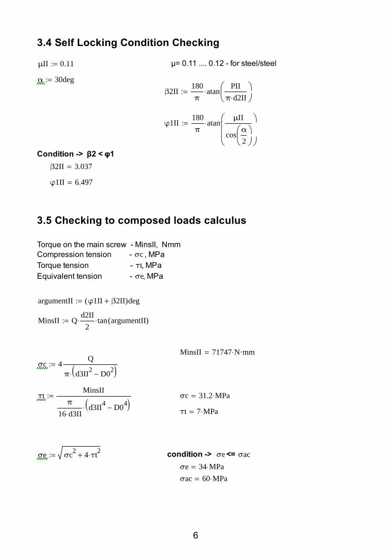
3.4 Self Locking Condition Checking
μII 0.11:= μ= 0.11 .... 0.12 - for steel/steel
α 30deg:=β2II
180π
atanPII
π d2II⋅
⋅:=
φ1II180π
atanμII
cosα
2
⋅:=
Condition -> β2 < φ1β2II 3.037=
φ1II 6.497=
3.5 Checking to composed loads calculus
Torque on the main screw - MinsII, NmmCompression tension - σc , MPaTorque tension - τt, MPa Equivalent tension - σe, MPa
argumentII φ1II β2II+( )deg:=
MinsII Qd2II
2⋅ tan argumentII( )⋅:=
MinsII 71747 N·mm⋅=σc 4
Q
π d3II2 D02−( )⋅:=
τtMinsII
π
16 d3II⋅d3II4 D04−( )⋅
:= σc 31.2 MPa⋅=
τt 7 MPa⋅=
σe σc2 4 τt2⋅+:= condition -> σe <= σac σe 34 MPa⋅=σac 60 MPa⋅=
6

4. Fixed Nut Design4.1 MaterialThe element will be made out of FC 200 SR ISO 185
Resistance to breaking from traction Rm = 200 MPa•Part's section diameter - from 2.5 mm .....50 mm•
4.2 Number of turns calculus z - number of turnsHpII - lenght of the nutpa - 7...13 MPa for steel/steel - 5...6 MPa for steel/ cast iron
Condition6 <= z <= 10
pa 5MPa:=
zII 4Q
π dII2 D1II2−( )pa⋅:=
zII 5.902= we choose z to be zII 9:=
HpII zII PII⋅:= HpII 72 mm⋅=
4.3 Turn checkingthe turn checking for bending and shearing
for bending
h 0.634 PII⋅:=
σai 45MPa:=Conditionσi <= σaiσi 3
Q D4II d2II−( )⋅
π D4II⋅ h2⋅ zII⋅:=
σi 7 MPa⋅=
for shearing
τaf 35MPa:=Conditionτf <= τafτf
Qπ D4II⋅ h⋅ zII⋅
:=
τf 2.3 MPa⋅=
7

4.4 Choosing the nut's dimensions
De - external diameter - De= D4+(8...10 mm)Dg - external diameter of the neck - Dg=De+(16...20 mm )hg - neck's height ( 8..10 mm )
De D4II 9mm+:=
Dg De 17mm+:=De 62 mm⋅=
hg 10mm:=Dg 79 mm⋅=
hg 10 mm⋅=
4.5 Checking the nut for composed loads
σi - traction tension , MPaτi - torsion tension, MPaσe - equivalent tension, MPa
σt 4Q
π De2 D4II2−( ) 22 MPa⋅=:=
τtMinsII
π
16DeDe4 D4II4−( )
3 MPa⋅=:=σat - 60..80 MPa - for steel - 40..45 MPa - for cast iron or bronze
σat 45MPa:=σe σt2 4 τt⋅( )2+ 26 MPa⋅=:=
Condition : σe <= σat
4.6 Neck checking
σs - reistance to crushingσas - allowed resistance to crushingτf - resistance to shearingτaf - allowed resistance to crushing
σs 4Q
π Dg2 De2−( ):=
τfQ
πDe hg⋅:=
σas 60MPa:=
τaf 35MPa:=σs 9.5 MPa⋅= conditions
σs <= σasτf <= τaf
τf 9.1 MPa⋅=
8

4.7 Choosing and checking the threadedbolt that fill fix the nut on the body
We will choose a M5,M6 or M8 threaded bolt with cilindrical head
We choose the M5x25 STAS 10422 with the below mentioned characteristics
d = 5 mm t = 1.62 mm n = 0.8 mm c1 = 1.2 mm d4 = 3.5 mm
c3 = 3 mm d1= 2.5 mm m = 2 mm
Mg - friction moment on the support surface of the neckMs - moment on the threaded bolt
μ = 0.15...0.20 - for steel/steelμ = 0.12...0.15 - for steel / cast ironcast iron / cast ironbronze / cast iron
μ 0.15:=
Mg13μ⋅ Q⋅
Dg3 De3−( )Dg2 De2−( )⋅:=
Ms MinsII Mg−:=MinsII 71747 N·mm⋅=
Mg 94574 N·mm⋅=Ms 22827− N·mm⋅=
Ms has a negative value so the bolt checking calculus is unnecessary
9

5. Body DesignlsI - main screw's lenghtlsII - secondary screw's lenght
HII HPII
PII PI+
⋅ 144.62 mm⋅=:=
lsII HII HpII+ 216.62 mm⋅=:=
Dci = De+ (2..6) mm
γ - 5...7 degrees
δ - 7...8 mm
δt - 10...12 mm
Dbe = Dbi+(30..50) mm
Dbi - measured on the drawing
H1 = HII+ (30...50) mm
HII - how much the secondary screw rises
Hc -=H1+HpII-hg+(0...10) mm
Dci De 4mm+:=
γ 7deg:=
δ 7mm:=
δt 10mm:=
Dbi 111.34mm:=Dbe Dbi 40mm+:=
HI HII 40mm+:=σc = body compression checking
σs = crushing checking for the support surface
σac = allowed body compression checking 60...80 MPa
σas = allowed crushing checking for the support surface 2...2.5 MPA
Hc HI HpII+ hg− 10mm+:=
σacc 70MPa:=σc 4
Q
π Dg2 Dci2−( )⋅⋅:= σs 4
Q
π Dbe2 Dbi2−( )⋅⋅:=
σas 2.5MPa:=
Dci 66 mm⋅=conditions σc <= σaccσs <= σas
Dbi 111.34 mm⋅=σc 12 MPa⋅=
Dbe 151.34 mm⋅=σs 2.16 MPa⋅=
HI 184.62 mm⋅=Hc 256.62 mm⋅= lsI HI HpI+ 229.62 mm⋅=:=
10

6. Cup calculusChoosing the bolt
ds=(0.15...0.25)dc
dc= d+(2..4) mm
d = nominal diameter of the main screw's thread
A bolt standardized cilindrical bolt must be used with d >= ds
We choose the M8x18 STAS 10422 with the following characteristics expressed in mm
d = 5 t = 1.6 n = 0.8 c1 = 1.2 d4 = 3.5 c3 = 3 d1 = 2.5 m = 2
d 28mm:=
dc d 4mm+ 32 mm⋅=:=
ds 0.25 dc⋅ 8 mm⋅=:=
Checking the bolt for shearing and crushing
τaf 80MPa:=
σas 120MPa:=
shearing
τaf= 65...80 MPa
σas= 100...120 MPa
Dc= (1.4...1.6)dc
τf 4MinsI
π dc⋅ ds2⋅⋅:=
τf 25 MPa⋅=
crushing - cupDc 1.4 dc⋅ 44.8 mm⋅=:= σs 4
MinsI
ds Dc2 dc2−( )⋅⋅:=
σs 20 MPa⋅=
crushing - end of the screw
σs 6MinsI
ds dc2⋅⋅:= conditions
τf <= τafσs <= σasσs 30 MPa⋅=
11

Checking the minimized section of the screw's head to composed loads σe , MPa
σcQ
πdc2
4⋅ ds dc⋅−
:=
τt 16MinsI
π dc3⋅ 1dsdc
−
⋅⋅:=
σe σc2 4 τt2⋅+:=
σac 60 MPa⋅=
σc 32 MPa⋅=
τt 8 MPa⋅=
σe 37 MPa⋅=
conditionσe <= σac
σe 37 MPa⋅=σac 60 MPa⋅=
7. Efficiency calculus
ηd2I tan β2I( )⋅ d2II tan β2II( )⋅+( )
d2I tan argumentI( )⋅ d2II tan argumentII( )⋅+:=
η 0.53=
12

8. Horizontal ratchet actioning mechanism calculus
b - gear thickness
1 - ratchet gear2 - ratchet3 - pin4 - splint5 - washer
6 - board7 - pusher8 - spring9 - adjustment screw10 - sheath
13

8.1 Crank length Mm - total moment•Fm - force with which the user acts •
(150 - 300 N)Lc - calculus length of the crank•
Mm MinsI MinsII+ 112043.18 N·mm⋅=:=
Fm 300N:=
k 1:=l0 - user grabing length•
(50 mm for n=1 and 100mm for n =2)n 1:=
l0 50mm:=n - number of workers ( 1 or 2 )•K - unsimultaneity of users action •
(K=1 for n=1 and K=0.8 for n=2Lc
Mmk n⋅ Fm⋅
373 mm⋅=:=
L Lc l0+:= Actual crank length L 423.48 mm⋅=
8.2 Extension calculus
extension length - LpLp - extension length•
L>200..200mm => Lm=(0.3 .. 0.4)L and Lp=L-Lm+l
l - guidance length of the extension• =50..80 mm
Lm 0.3 L⋅ 127.043 mm⋅=:=
l 50mm:=
Lp L Lm− l+:=
Lp 346.434 mm⋅=
extension diameter - dpe
σai 120MPa:=
dpe3 32 k⋅ n⋅ Fm⋅ Lp l0− l−( )⋅[ ]
π σai⋅18.445 mm⋅=:=
dpe 19mm:=
We will use comercial pipe 19 / OL45 STAS 333
14

8.3 Ratchet wheel calculus
8.3.1 Material
The element will be made out of OLC 45 STAS 880
Flow limit ReH (Rp02) -> 370 - 500 MPa - heat treated : tempering and high temperature tempering- Resistance to breaking from traction Rm - 630..850 MPa
8.3.2 Choosing the dimensions d D4II:=d 53 mm⋅=
Dm 1.6 d⋅ 84.8 mm⋅=:=
z 10:=
πDm2z
13.3 mm⋅=
b 12mm:=
h 0.7 b⋅ 8.4 mm⋅=:=
Dm = (1.6....1.8)d •b<= π*Dm/2z•h=(0.6 .... 0.8)b•a <= 0.5*d - (1..2)mm for hexagonal profile•
Di Dm h−:=De Dm h+:=
a 0.5 d⋅ 2mm−:=
b 12 mm⋅= Di 76.4 mm⋅=h 8.4 mm⋅= De 93.2 mm⋅=a 24.5 mm⋅= Dm 84.8 mm⋅=z 10=
8.3.2 Checking the gear for loads and stresses
tooth checking for bending σi MPa• δ - tooth thickness =(6...10)mmδ 9mm:=
F12 Mm⋅( )Dm
2643 N⋅=:=condition σi <= σai
σi3 F1⋅ h⋅( )
b2δ⋅
51 MPa⋅=:= σi 51 MPa⋅=σai 120MPa:=
15

tooth checking for shearing τ1 MPa•
τfF1b δ⋅
:= condition τf <= τaf
τf 24 MPa⋅=τaf 100MPa:=
τaf 100 MPa⋅=
tooth contact surface checking for crushing σs MPa•
σsF1δ h⋅
:= condition σs <= σas
σas 120MPa:= σs 35 MPa⋅=σas 120 MPa⋅=
checking of polygonal contour assembly for crushing σs MPa•
n 6:= n = 6 for hexagonal profile assembly•
δt δ 2mm+ 11 mm⋅=:=
σs 2Mm
n a2⋅ δt⋅:=
condition σs <= σas
σs 5.66 MPa⋅=
σas 120 MPa⋅=
16

8.4 Ratchet calculus8.4.1 Material
The element will be made out of OLC 45 STAS 880
Flow limit ReH (Rp02) -> 370 - 500 MPa - heat treated : tempering and high temperature tempering- Resistance to breaking from traction Rm - 630..850 MPa
8.4.2 Choosing the dimensions
Dm 84.8 mm⋅=
l1 = (0.85..1.0)Dm•α = γ+(3...5)deg•db= 6...12mm•m = (1.75 ....2.25)db•
l1 0.85Dm 72.08 mm⋅=:=
db 10mm:=
z 10=
R db:=
m 1.8 db⋅:=
γ 2180π
⋅ atanπ
4 z⋅tan
180π
asinDm2l1
⋅ deg⋅
⋅
6.539=:=
α γ 4+:= m 18 mm⋅=g 14.16mm:= l1 72.08 mm⋅= δ 9 mm⋅=
e 7.97mm:= db 10 mm⋅= γ 6.539=
sa 1.72mm:= R 10 mm⋅= α 10.539=
De 93.2 mm⋅=
Di 76.4 mm⋅=Dm 84.8 mm⋅=
z 10=
b 12 mm⋅=h 8.4 mm⋅=
17
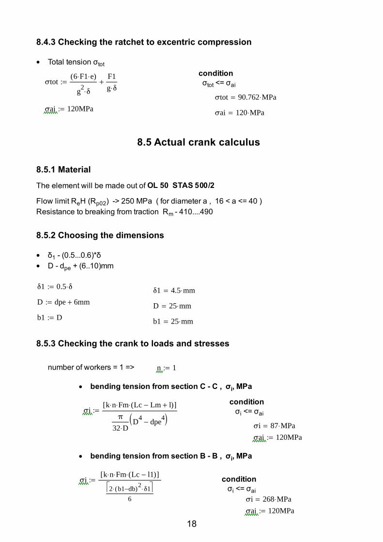
8.4.3 Checking the ratchet to excentric compression
Total tension σtot •condition σtot <= σaiσtot
6 F1⋅ e⋅( )
g2δ⋅
F1g δ⋅
+:=
σtot 90.762 MPa⋅=σai 120MPa:=
σai 120 MPa⋅=
8.5 Actual crank calculus
8.5.1 Material
The element will be made out of OL 50 STAS 500/2
Flow limit ReH (Rp02) -> 250 MPa ( for diameter a , 16 < a <= 40 )Resistance to breaking from traction Rm - 410....490
8.5.2 Choosing the dimensions
δ1 - (0.5...0.6)*δ•D - dpe + (6..10)mm•
δ1 0.5 δ⋅:=δ1 4.5 mm⋅=
D dpe 6mm+:= D 25 mm⋅=b1 D:= b1 25 mm⋅=
8.5.3 Checking the crank to loads and stresses
number of workers = 1 => n 1:=
bending tension from section C - C , σi, MPa•
condition σi <= σaiσi
k n⋅ Fm⋅ Lc Lm− l+( )⋅[ ]π
32 D⋅D4 dpe4−( )
:=
σi 87 MPa⋅=σai 120MPa:=
bending tension from section B - B , σi, MPa •
σik n⋅ Fm⋅ Lc l1−( )⋅[ ]
2 b1 db−( )2⋅ δ1⋅ 6
:= condition σi <= σai
σi 268 MPa⋅=σai 120MPa:=
18

8.6 Bolt of the ratchet calculus
pin checking for shearing τf , MPa•
τfF1
2π db2⋅( )
4
⋅
:=
condition τf <= τaf
τf MPa⋅=
τaf 80MPa:=
pin checking for crushing σs , MPa•
condition σs <= σasσs
F1db δt⋅
:=
σs 24 MPa⋅=
σas 80MPa:=
pin checking for bending σi , MPa•
condition σi <= σai
σi8 F1⋅
δ
2δ1+
⋅
π db3⋅:= σi 61 MPa⋅=
σai 120MPa:=
19

8.7 Elicoidal compresion spring calculusthe spring that mantains the ratchet in contact with the ratchet gear's teeth
i - spring's index•k - shape coeficient •
k=1.2 - for i=8 k=1.17 - for i=9 k=1.16 - for i=10
d - winding's diameter • recommended d=0.8...1.5mm d=0.8 ; 1 ; 1.2 ; 1.4 ; 1.5
Dm - average winding diameter •
d 1.2mm:=
i 8:=
Dm i d⋅:= k 1.2:=Dm 9.6 mm⋅=
F1 - fitting strength•
F1 5N:=
n - active number of windings •nt - total number of windings•nc - end windings number•
n 6:=nc 1.5:=nt n nc+:=
δ1 - fitting arrow, mm•δmax - maximum arrow, mm•
- measured on drawing
G 85000MPa:= sa 1.72 mm⋅=
δ18 F1⋅ Dm3⋅( )
G d4⋅n⋅ 1.2 mm⋅=:=
δmax δ1 sa+:=
δmax 2.92 mm⋅=
Fmax - maximum working•force
Fmax F1δmaxδ1
⋅ 12N=:=
τt - torsion stress, MPa• τat=650MPa for OLC65
conditionτt <=τat
τt 8 MPa⋅=τt
8 k⋅ Fmax⋅ Dm⋅( )
π d3⋅:=
τat 650MPa:=
20

c - spring's rigidity, MPa•
cG d4⋅( )
8 n⋅ Dm3⋅:=
c 4.15 10 3−× m MPa⋅=
Hb - length of blocked spring•Hb nt d⋅:=
Hb 9 mm⋅=
t - loaded spring's pitch• Δ>=0.1d - windings play of the spring loaded by Fmax
Δ 0.1 d⋅ 2mm+:=
t dδmax
n+ Δ+:=
Δ 2.12 mm⋅=
t 3.807 mm⋅=
H0 - unloaded spring length, mm•H1 - length according to fitting force, mm•Hm - length according to Fmax•
H0 Hb n t d−( )⋅+:= H0 24.645 mm⋅=
H1 H0 δ1−:= H1 23.44 mm⋅=
Hm H0 δmax−:= Hm 21.72 mm⋅=
Fb - force of blocked spring ( winding on winding )• δb= δmax+Δn
δb δmax Δ n⋅+:= δb 15.64 mm⋅=
Fb Fmaxδbδmax
⋅:= Fb 65N=
D - external diameter •D1 - interior diameter•
D Dm d+:= D 10.8 mm⋅=
D1 Dm d−:= D1 8.4 mm⋅=
21

α0 - winding's tilt angle of unloaded spring•ls - semifabricated length•
α0 atant
π Dm⋅deg⋅
:=
lsπ Dm⋅ nt⋅( )
cos α0 deg⋅( )
:=
α0 0.002=
ls 226.19 mm⋅=
22
Top Related