


Languages
Pages
Legal


Orthogonal Frequency Division Multiplexing Rafael Suero Samboy Independent Study Professor: Drew Maywar 1/29/2010
Table of Contents OFDM System Overview ............................................................................................................................... 3
OFDM General Discussion ......................................................................................................................... 3
Domains ........................................................................................................................................................ 3
Orthogonality ............................................................................................................................................ 3
OFDM Transmitter and Receiver Diagram ................................................................................................ 8
System Overview ...................................................................................................................................... 8
Initial Signal ................................................................................................................................................. 10
Interleaving and Error Correction Codes ............................................................................................ 10
Serial to Parallel Conversion ............................................................................................................... 11
Symbol Mapping (Digital Modulation) ........................................................................................................ 11
OFDM Modulation: The IFFT Block ............................................................................................................. 13
The Transmitted Signal ........................................................................................................................... 15
OFDM Demodulation : FFT Block ................................................................................................................ 16
Symbol De-Mapping ............................................................................................................................ 17
Data Detection ............................................................................................................................................ 18
Final Section ................................................................................................................................................ 19
Future Work ................................................................................................................................................ 20
Sources and Endnotes ................................................................................................................................. 21

OFDM System Overview
OFDM General Discussion Orthogonal Frequency Division Multiplexing (OFDM) is a frequency-division multiplexing (FDM) scheme utilized as a digital multi-carrier modulation method. A large number of closely-spaced orthogonal subcarriers are used to carry data. OFDM is a sophisticated technique that combines modulation and multiplexing. Modulation: a mapping of the information on changes in the carrier phase, frequency, amplitude or combination of these properties. Multiplexing: refers to FDM (Frequency Division Multiplexing) , a method of sharing a bandwidth with other independent data channels.
Domains
Most of the contents in this paper are classified in three domains; these classifications can be
appreciated along the figures and explanations of the paper.
Domain A: Bits to Frequency Domain. Refers to the signal stages before the IFFT transformation of the
signal to the time domain. Contents: Initial Signal, Interleaving and Error Correction Codes, Symbol
Mapping, etc.
Domain B: Time Domain. Refers to the system stages from the IFFT block until the input of the FFT block
in the receiver. Contents: IFFT Block, The transmitted Signal and processing in the receiver before the
FFT block).
Domain C: Receiver Frequency Domain to bits . System stages from the FFT Block output until the
received bit stream. Contents: FFT Block, Symbol De-Mapping, Data Detection.
Orthogonality In a normal FDM system, the many carriers are spaced apart in such way that the signals can be separated and received using conventional filters and demodulators. In such receivers, guard bands have to be introduced between the different carriers, and the introduction of these guard bands in the frequency domain results in a lowering of the spectral efficiency as shown in the figure below.
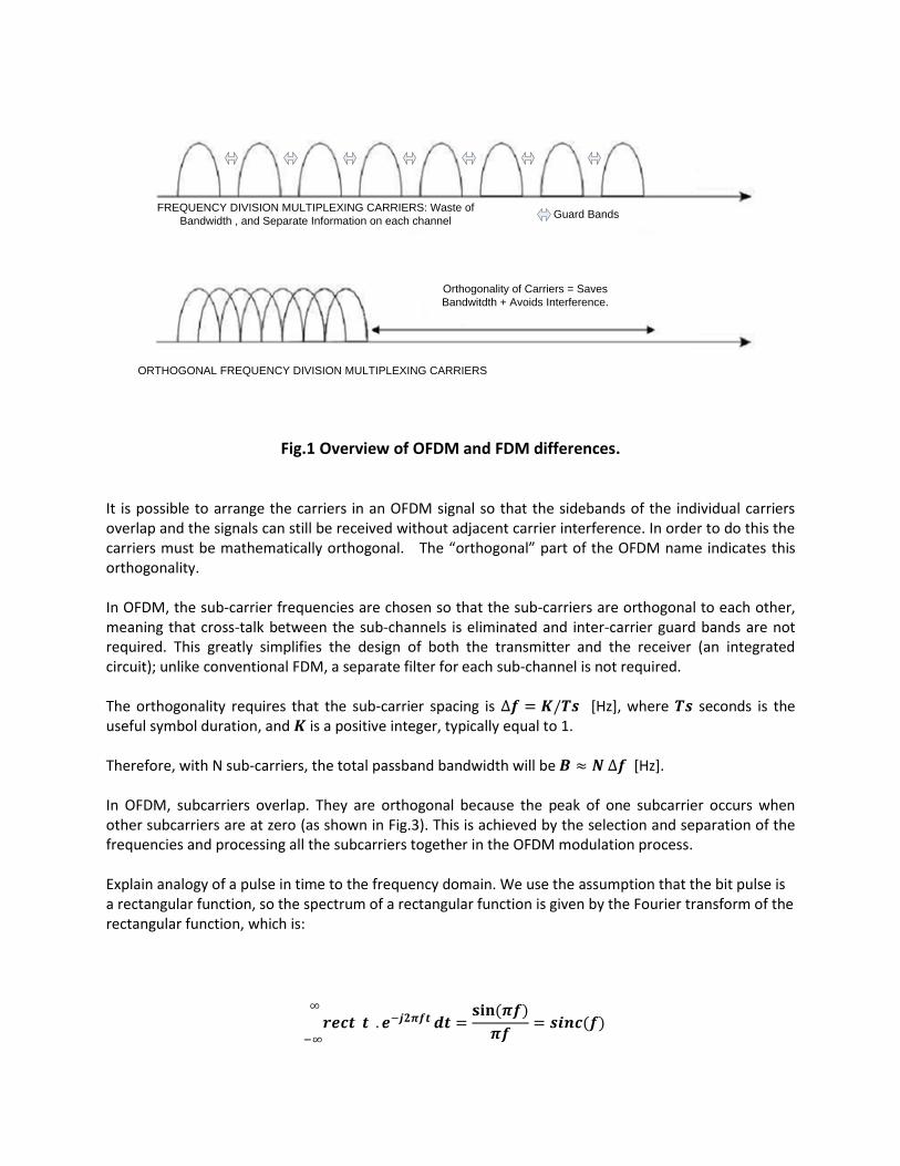
Orthogonality of Carriers = Saves
Bandwitdth + Avoids Interference.
ORTHOGONAL FREQUENCY DIVISION MULTIPLEXING CARRIERS
FREQUENCY DIVISION MULTIPLEXING CARRIERS: Waste of
Bandwidth , and Separate Information on each channelGuard Bands
Fig.1 Overview of OFDM and FDM differences.
It is possible to arrange the carriers in an OFDM signal so that the sidebands of the individual carriers overlap and the signals can still be received without adjacent carrier interference. In order to do this the carriers must be mathematically orthogonal. The “orthogonal” part of the OFDM name indicates this orthogonality. In OFDM, the sub-carrier frequencies are chosen so that the sub-carriers are orthogonal to each other, meaning that cross-talk between the sub-channels is eliminated and inter-carrier guard bands are not required. This greatly simplifies the design of both the transmitter and the receiver (an integrated circuit); unlike conventional FDM, a separate filter for each sub-channel is not required. The orthogonality requires that the sub-carrier spacing is [Hz], where seconds is the useful symbol duration, and is a positive integer, typically equal to 1. Therefore, with N sub-carriers, the total passband bandwidth will be [Hz]. In OFDM, subcarriers overlap. They are orthogonal because the peak of one subcarrier occurs when other subcarriers are at zero (as shown in Fig.3). This is achieved by the selection and separation of the frequencies and processing all the subcarriers together in the OFDM modulation process. Explain analogy of a pulse in time to the frequency domain. We use the assumption that the bit pulse is a rectangular function, so the spectrum of a rectangular function is given by the Fourier transform of the rectangular function, which is:
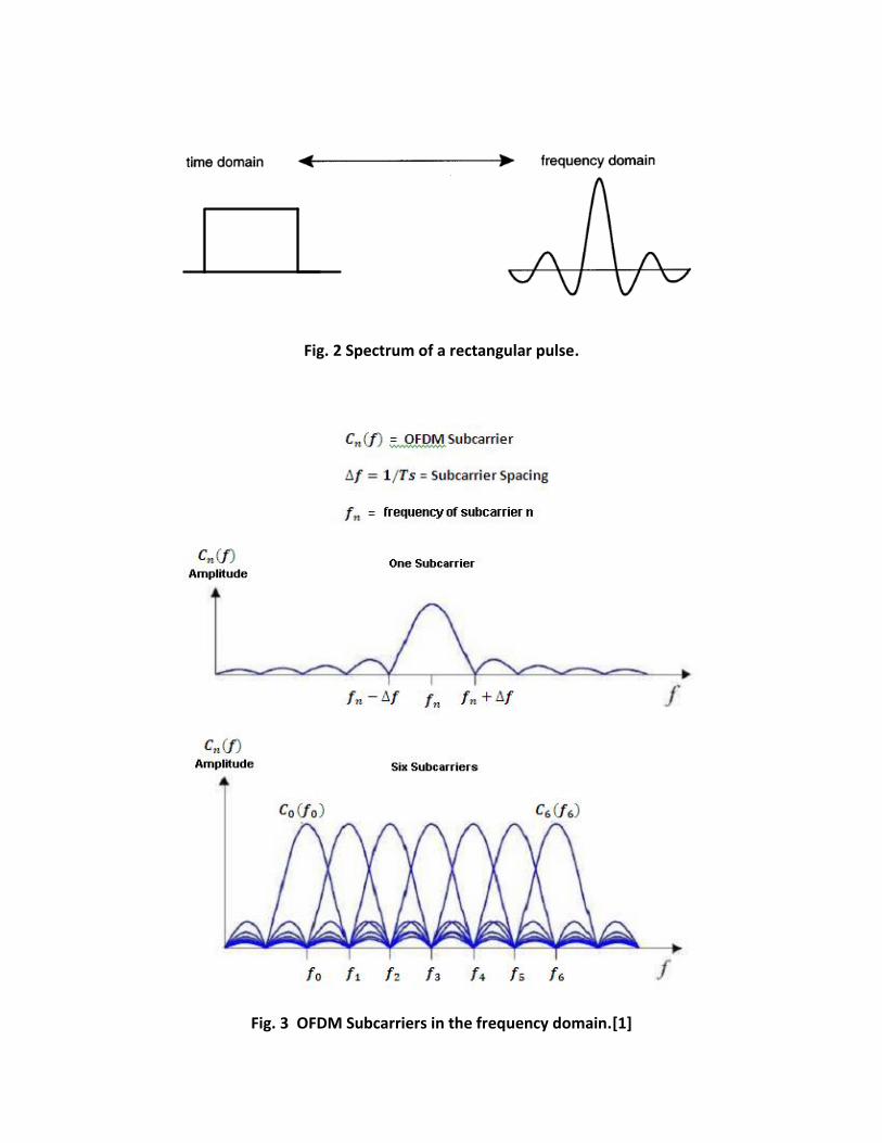
Fig. 2 Spectrum of a rectangular pulse.
Fig. 3 OFDM Subcarriers in the frequency domain.[1]
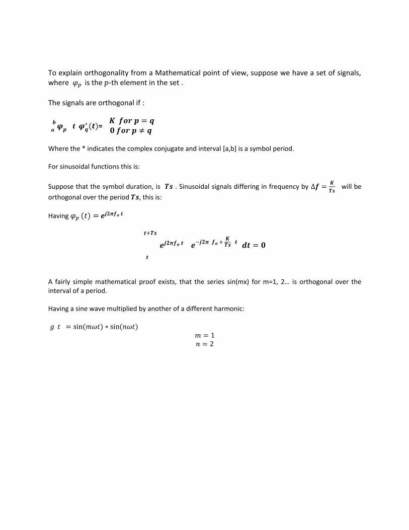
To explain orthogonality from a Mathematical point of view, suppose we have a set of signals, where is the -th element in the set .
The signals are orthogonal if :
=
Where the * indicates the complex conjugate and interval [a,b] is a symbol period. For sinusoidal functions this is:
Suppose that the symbol duration, is . Sinusoidal signals differing in frequency by will be
orthogonal over the period , this is:
Having
A fairly simple mathematical proof exists, that the series sin(mx) for m=1, 2… is orthogonal over the interval of a period. Having a sine wave multiplied by another of a different harmonic:

Fig 4. Plot of . By trigonometric relationship, this product is equal to the sum of two sinusoids of frequencies (n-m) and (n+m).
These two components are each a sinusoid, so the integral over one period is equal to zero
We conclude that when we multiply a sinusoid of frequency n by a sinusoid of frequency m/n, the area under the product is zero. In general for all integers n and m,
are all orthogonal to each other. This idea is key to understanding OFDM. The orthogonality allows simultaneous transmission on a lot of sub-carriers in a tight frequency space without interference from each other. In essence this technique is similar to CDMA, where codes are used to make data sequences independent (also orthogonal) which allows many independent users to transmit in same space successfully.
OFDM Transmitter and Receiver Diagram
System Overview
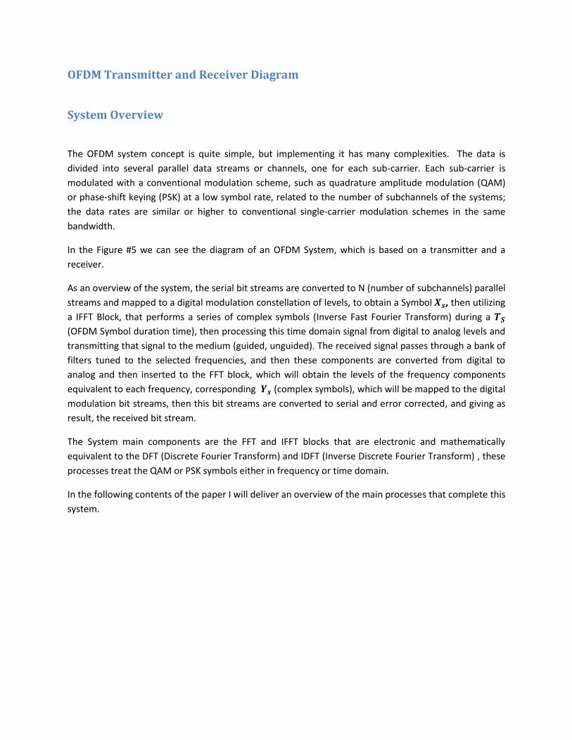
The OFDM system concept is quite simple, but implementing it has many complexities. The data is
divided into several parallel data streams or channels, one for each sub-carrier. Each sub-carrier is
modulated with a conventional modulation scheme, such as quadrature amplitude modulation (QAM)
or phase-shift keying (PSK) at a low symbol rate, related to the number of subchannels of the systems;
the data rates are similar or higher to conventional single-carrier modulation schemes in the same
bandwidth.
In the Figure #5 we can see the diagram of an OFDM System, which is based on a transmitter and a
receiver.
As an overview of the system, the serial bit streams are converted to N (number of subchannels) parallel
streams and mapped to a digital modulation constellation of levels, to obtain a Symbol , then utilizing
a IFFT Block, that performs a series of complex symbols (Inverse Fast Fourier Transform) during a
(OFDM Symbol duration time), then processing this time domain signal from digital to analog levels and
transmitting that signal to the medium (guided, unguided). The received signal passes through a bank of
filters tuned to the selected frequencies, and then these components are converted from digital to
analog and then inserted to the FFT block, which will obtain the levels of the frequency components
equivalent to each frequency, corresponding (complex symbols), which will be mapped to the digital
modulation bit streams, then this bit streams are converted to serial and error corrected, and giving as
result, the received bit stream.
The System main components are the FFT and IFFT blocks that are electronic and mathematically
equivalent to the DFT (Discrete Fourier Transform) and IDFT (Inverse Discrete Fourier Transform) , these
processes treat the QAM or PSK symbols either in frequency or time domain.
In the following contents of the paper I will deliver an overview of the main processes that complete this
system.


Initial Signal
Interleaving and Error Correction Codes
The initial signal is a serial bit stream of data. The bit stream is coded and interleaved in some
implementations.
For the error correction, the OFDM system uses FEC (Forward Error Correction), where the transmitter
encodes the data with an error-correcting code (most likely Convolutional codes, Reed-Solomon, Viterbi,
Turbo or BCH Codes) and sends the coded message. The receiver never sends anything back to the
transmitter; otherwise it decodes and decides what it receives into the “most likely data”. The robust
design of the encoding/decoding structure gives integrity and protection of the data against noise and
error bursts.
Interleaving refers to a way of arranging data in a non contiguous way to enhance the system
performance by avoiding the existence of more errors interpreted by the error correction decoder and
obtain fewer error bursts.
Using a stream of letters instead of bits, I present an example of interleaving and the advantages of
including it on a transmission system:
“To reduce the effect of such burst errors, the bits of a number of codewords are interleaved before being
transmitted. This way, a burst error affects only a correctable number of bits in each codeword, and the
decoder can decode the codewords correctly.
Fig 6. Interleaving Example
In each of the codewords aaaa, eeee, ffff, gggg, only one bit is altered, so one-bit error-correcting-code
will decode everything correctly. ” [2]
One disadvantage that interleaving brings is latency, because of the time it takes to receive the blocks of
data and the analysis it has to do before returning the critical data that is received, this is the main
reason why interleaving is not always included in an OFDM System.

Serial to Parallel Conversion
Suppose that we have the serial bit stream 1000 1010 1001 0000 1001 0101 1111 1100 and the number
of subchannels equal to 4, we can convert from parallel to serial using this convention:
F1 F2 F3 F4 1 0 0 0
1 0 1 0
1 0 0 1
0 0 0 0
1 0 0 1
0 1 0 1
1 1 1 1
1 1 0 0
Now , each column bit stream corresponds to a subchannel with frequency F (orthogonal to the other
frequencies).
Symbol Mapping (Digital Modulation)
The data of an OFDM system is mapped (digitally modulated) using common digital modulation schemes
as QAM or PSK. The serial binary data stream from the N subchannels is converted into frequency
domain symbols of frequency which are complex numbers representing constellation points of the
chosen digital modulation scheme.
In PSK have the same amplitude and the phase change, and in QAM both amplitude and
phase change. are also called the I and Q components of a signal.
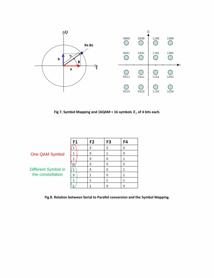
Fig 7. Symbol Mapping and 16QAM = 16 symbols of 4 bits each.
One QAM Symbol
Different Symbol in
the constellation
Fig 8. Relation between Serial to Parallel conversion and the Symbol Mapping.
OFDM Modulation: The IFFT Block
OFDM symbol generation is like a Fourier series, in which the subcarrier of each stream has a different
frequency range, and the complex Fourier coefficient is the complex-valued symbol of the constellation
diagram.
OFDM systems are implemented using the combination of the FFT (Fast Fourier Transform) and the
IFFT(Inverse Fast Fourier Transform). These blocks are versions of the DFT (Discrete Fourier Transform)
IDFT (Inverse Discrete Fourier Transform) , but more efficiently to implement.
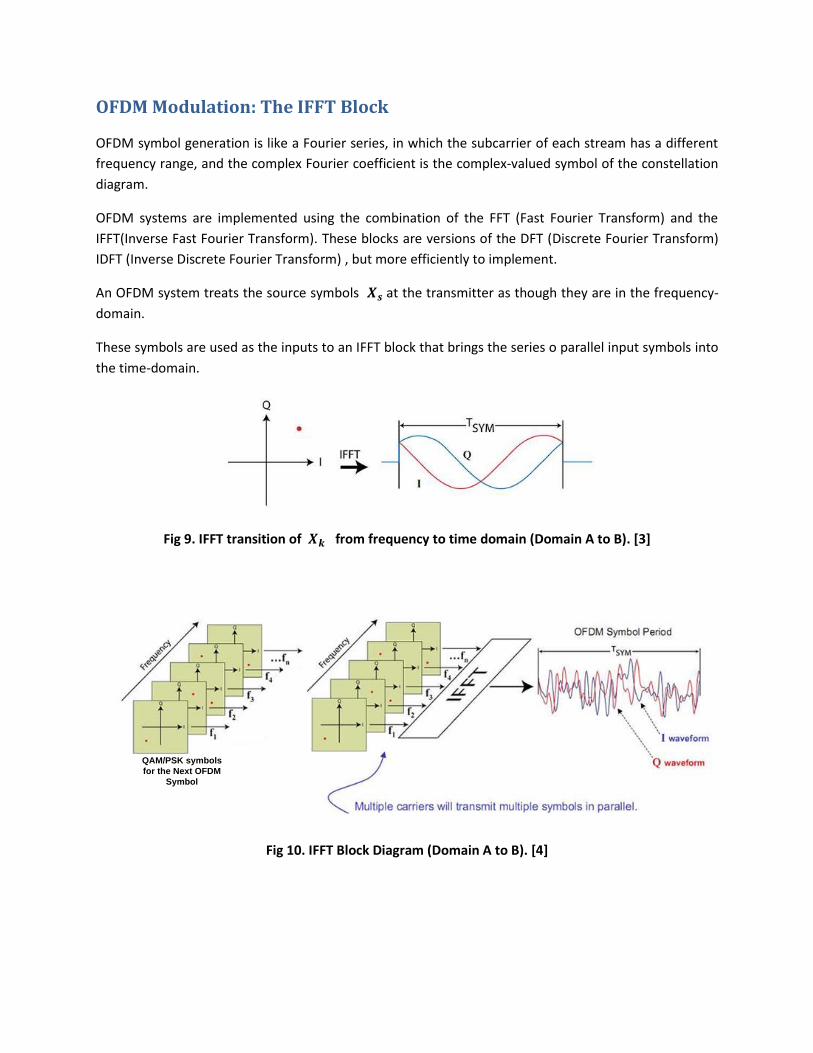
An OFDM system treats the source symbols at the transmitter as though they are in the frequency-
domain.
These symbols are used as the inputs to an IFFT block that brings the series o parallel input symbols into
the time-domain.
Fig 9. IFFT transition of from frequency to time domain (Domain A to B). [3]
QAM/PSK symbols
for the Next OFDM
Symbol
Fig 10. IFFT Block Diagram (Domain A to B). [4]
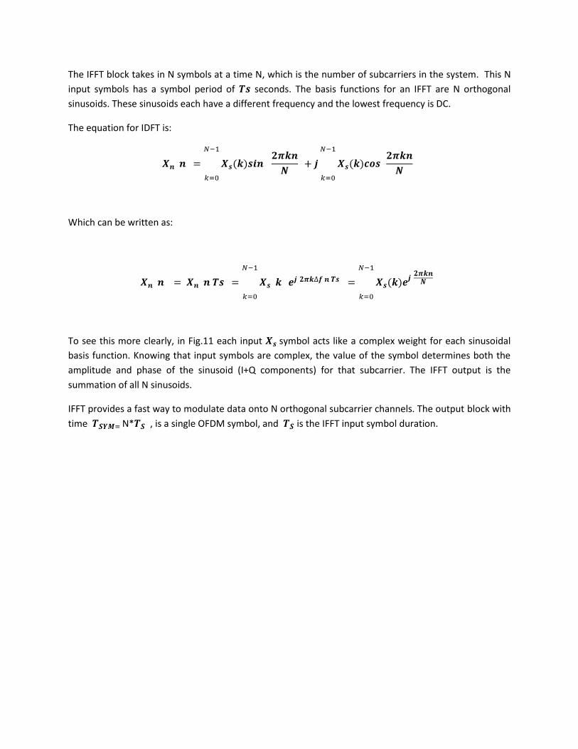
The IFFT block takes in N symbols at a time N, which is the number of subcarriers in the system. This N
input symbols has a symbol period of seconds. The basis functions for an IFFT are N orthogonal
sinusoids. These sinusoids each have a different frequency and the lowest frequency is DC.
The equation for IDFT is:
Which can be written as:
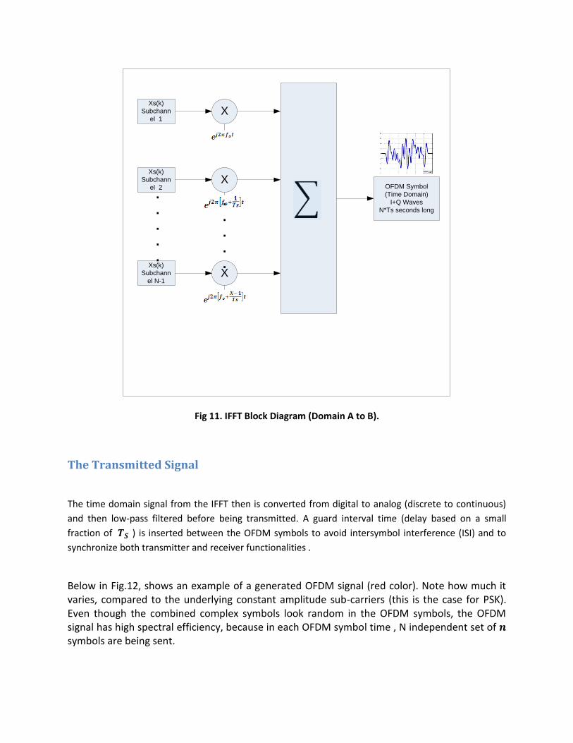
To see this more clearly, in Fig.11 each input symbol acts like a complex weight for each sinusoidal
basis function. Knowing that input symbols are complex, the value of the symbol determines both the
amplitude and phase of the sinusoid (I+Q components) for that subcarrier. The IFFT output is the
summation of all N sinusoids.
IFFT provides a fast way to modulate data onto N orthogonal subcarrier channels. The output block with
time N* , is a single OFDM symbol, and is the IFFT input symbol duration.
X
X
XXs(k)
Subchann
el 1
Xs(k)
Subchann
el 2
Xs(k)
Subchann
el N-1
.
.
.
.
.
.
.
.
.
.
OFDM Symbol
(Time Domain)
I+Q Waves
N*Ts seconds long
Fig 11. IFFT Block Diagram (Domain A to B).
The Transmitted Signal
The time domain signal from the IFFT then is converted from digital to analog (discrete to continuous)
and then low-pass filtered before being transmitted. A guard interval time (delay based on a small
fraction of ) is inserted between the OFDM symbols to avoid intersymbol interference (ISI) and to
synchronize both transmitter and receiver functionalities .
Below in Fig.12, shows an example of a generated OFDM signal (red color). Note how much it varies, compared to the underlying constant amplitude sub-carriers (this is the case for PSK). Even though the combined complex symbols look random in the OFDM symbols, the OFDM signal has high spectral efficiency, because in each OFDM symbol time , N independent set of symbols are being sent.

Fig 12. The Transmitted Signal (Red) over N PSK subchannels. [5]
(Domain B)
Spectral Efficiency is given by:
[bits/s/Hz]
Q= Number of QAM or PSK Levels
OFDM Demodulation : FFT Block
After filtering the received signal, the receiver acts as a bank of demodulators ,filtering the N orthogonal
frequencies from each subchannels, and then feeding these filtered signals to an FFT block, in a parallel
fashion , then this block translates the time domain signal (Amplitude vs. time) to the frequency domain
(Amplitude vs frequency) by obtaining the amplitude levels of each carrier by integrating over a symbol
period to recover the raw data (this values correspond to the received that I call now ).

Fig 13. The Transmitted FFT block function (Domain B to C).
The equation performed by a FFT block is the Discrete Fourier Transform, which is given by:
The output of the FFT block will be ideally the original symbols that were sent to the IFFT at the
transmitter, this is .
The receiver also takes into account the guard interval time between OFDM symbols so that the system
keeps synchronized, this could be taken into account inside the OFDM Integrated circuit, or using DSP in
the computers or more robust implementations.
Symbol De-Mapping
When mapped in the in the complex plane, the FFT output samples, will result as symbol points in
the digital modulation constellation, such as 16-QAM (Fig.14).
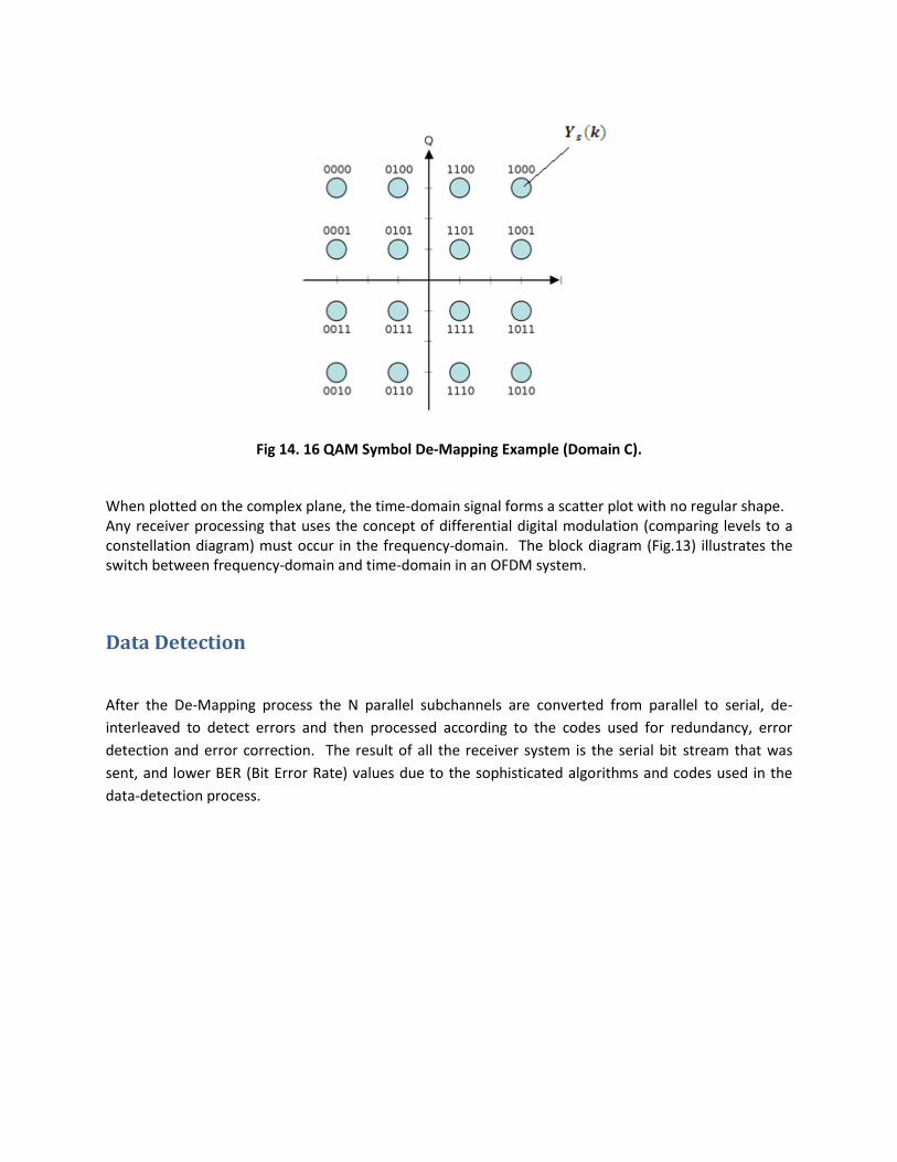
Fig 14. 16 QAM Symbol De-Mapping Example (Domain C).
When plotted on the complex plane, the time-domain signal forms a scatter plot with no regular shape. Any receiver processing that uses the concept of differential digital modulation (comparing levels to a constellation diagram) must occur in the frequency-domain. The block diagram (Fig.13) illustrates the switch between frequency-domain and time-domain in an OFDM system.
Data Detection
After the De-Mapping process the N parallel subchannels are converted from parallel to serial, de-
interleaved to detect errors and then processed according to the codes used for redundancy, error
detection and error correction. The result of all the receiver system is the serial bit stream that was
sent, and lower BER (Bit Error Rate) values due to the sophisticated algorithms and codes used in the
data-detection process.
Final Section
Initial proposals for OFDM were made in the 60s and the 70s. In these days, we can see many
implementations of this technique, which is used extensively in broadband wired and wireless
telecommunication transmission systems because it enhances and brings many alternatives to
intersymbol interference , noise , fading and error bursts caused by a dispersive and noisy channel, as
data rates increase to the point where, digital differential modulation schemes like quadrature
amplitude modulation (QAM) or PSK are used, and a high spectral efficiency are needed.
Another important thing about OFDM is that deals with the complexity of a transmission system from
the analog to the digital domain mainly because of the use of precise analog filters, symbol mapping and
error detection and correcting codes.
Despite these important advantages of OFDM, it is only recently that it has been considered for optical
communications.
“The following list is a summary of existing technologies where OFDM is being applied:
Cable
• ADSL and VDSL broadband access via POTS copper wiring.
• Power Line Communication (PLC)
• Multimedia over Coax Alliance (MoCA) home networking.
• ITU-T G.hn, a standard which provides high-speed local area networking over existing home
wiring (power lines, phone lines and coaxial cables).
• DVB-C2, an enhanced version of the DVB-C digital cable TV standard.
Wireless
• The wireless LAN (WLAN) radio interfaces IEEE 802.11a, g, n and HIPERLAN/2.
• The digital radio systems DAB/EUREKA 147, DAB+, Digital Radio Mondiale, HD Radio, T-DMB and
ISDB-TSB.
• The terrestrial digital TV systems DVB-T and ISDB-T.
• The terrestrial mobile TV systems DVB-H, T-DMB, ISDB-T and MediaFLO forward link.
• The cellular network's Flash-OFDM.
• The mobile broadband 3GPP Long Term Evolution air interface named High Speed OFDM Packet
Access (HSOPA).
• The Wireless MAN / Fixed Broadband Wireless Access (BWA) standard IEEE 802.16 (or WiMAX).
• The Mobile Broadband Wireless Access (MBWA) standards IEEE 802.20, IEEE 802.16e (Mobile
WiMAX) and WiBro.
• The wireless Personal Area Network (PAN) Ultra-wideband (UWB) IEEE 802.15.3a
implementation suggested by WiMedia Alliance.” [6]
Future Work
Many options exist inside this section, OFDM systems are being widely used in these days , among the
things that could be done in the future regarding to this paper I can mention:
- OFDM System Simulation: Using Matlab, PSpice or other tool.
- OFDM System Implementation: Take the simulated system to real.
- Optical OFDM: Using the techniques mentioned in the Independent Study (MZM, Direct and
Coherent Modulation).
- Digital Signal Processing: Research and simulate the algorithms that make possible and the cyclic
prefix and data detection and reduce the errors in the system.
- Error Correcting Codes: Study and implement the algorithms that perform the error detection
and correction in the OFDM system.
Sources and Endnotes
REFERENCES
1) OFDM and MC-CDMA, A Primer. L.Hanzo, T.Keller . IEEE Press. 2006.
2) Applications of OFDM and CDMA Wideband Wireless Communications. Henrik Schulze, Christian
Luders John Wiley & Sons .September 2005.
3) OFDM for Wireless Communications Systems. RamjeePrasad. Artech House.
4) ORTHOGONAL FREQUENCY DIVISION MULTIPLEXING. WIKIPEDIA.
http://en.wikipedia.org/wiki/Orthogonal_frequency-division_multiplexing
5) Here's how OFDM works and how it is used. Alister Burr, Emmanuel Jaffrot, Eduardo Rodrigues de
Lima, and Werner Teich.
http://www.dspdesignline.com/210600658;jsessionid=041D1D4M3ECWBQE1GHRSKH4ATMY32
JVN?pgno=5
6) An Overview of OFDM .
http://mobilewireless.wordpress.com/2008/03/01/an-overview-of-ofdm/
7) Intuitive Guide to Principles of Communications- ORTHOGONAL FREQUENCY DIVISION MULTIPLEXING. Charan Langton. www.complextoreal.com/chapters/ofdm2.pdf
8) OFDM for Optical Communications- Jean Armstrong ,Senior Member,IEEE .
http://www.opticsinfobase.org/abstract.cfm?URI=JLT-27-3-189
6) The Principles of OFDM. Louis Litwin and Michael Pugel
http://mobiledevdesign.com/tutorials/radio_principles_ofdm/index.html
7) OFDM Uncovered Part 1: The Architecture
http://www.commsdesign.com/design_corner/OEG20020502S0013
8) OFDM – Jean Armstrong. La Trobe University
www.docstoc.com/.../OFDM-–-Orthogonal-Frequency-Division-Multiplexing

9) An Introduction to Orthogonal Frequency Division Multiplex Technology. 2007-2008. Keithley
Instruments Inc.
http://www.ieee.li/pdf/viewgraphs/introduction_orthogonal_frequency_division_multiplex.pdf
10) An introduction to digital modulation and OFDM techniques. M.C.D. Maddocks. British Broadcast
Corporation
Endnotes (Citations)
[1] An Overview of OFDM.
http://mobilewireless.wordpress.com/2008/03/01/an-overview-of-ofdm/
[2] Interleaving, WIKIPEDIA, http://en.wikipedia.org/wiki/Interleaving
[3,4] An Introduction to Orthogonal Frequency Division Multiplex Technology. 2007-2008. Keithley
Instruments Inc.
http://www.ieee.li/pdf/viewgraphs/introduction_orthogonal_frequency_division_multiplex.pdf
[5] Intuitive Guide to Principles of Communications- ORTHOGONAL FREQUENCY DIVISION MULTIPLEXING. Charan Langton. www.complextoreal.com/chapters/ofdm2.pdf
[6] ORTHOGONAL FREQUENCY DIVISION MULTIPLEXING. WIKIPEDIA.
http://en.wikipedia.org/wiki/Orthogonal_frequency-division_multiplexing
Top Related