


![Report on Proposals – November 2010 NFPA 79 · 2016. 2. 22. · IEC 60204-1 ex8sting IEC 60204-1 Proposed change NFPA 79 existing NFPA 79 Proposed change [Ariel Unicode MS 12pt]](https://static.fdocuments.net/doc/165x107/60b2a55608b23169c13b8e42/report-on-proposals-a-november-2010-nfpa-79-2016-2-22-iec-60204-1-ex8sting.jpg)


Languages
Pages
Legal


Installation InstructionsOriginal Instructions
OEM Starter Frame and Components (400 A, 2400…7200V)Bulletin Number 1503

Important User Information
Read this document and the documents listed in the additional resources section about installation, configuration, and operation of this equipment before you install, configure, operate, or maintain this product. Users are required to familiarize themselves with installation and wiring instructions in addition to requirements of all applicable codes, laws, and standards.
Activities including installation, adjustments, putting into service, use, assembly, disassembly, and maintenance are required to be carried out by suitably trained personnel in accordance with applicable code of practice.
If this equipment is used in a manner not specified by the manufacturer, the protection provided by the equipment may be impaired.
In no event will Rockwell Automation, Inc. be responsible or liable for indirect or consequential damages resulting from the use or application of this equipment.
The examples and diagrams in this manual are included solely for illustrative purposes. Because of the many variables and requirements associated with any particular installation, Rockwell Automation, Inc. cannot assume responsibility or liability for actual use based on the examples and diagrams.
No patent liability is assumed by Rockwell Automation, Inc. with respect to use of information, circuits, equipment, or software described in this manual.
Reproduction of the contents of this manual, in whole or in part, without written permission of Rockwell Automation, Inc., is prohibited.
Throughout this manual, when necessary, we use notes to make you aware of safety considerations.
Labels may also be on or inside the equipment to provide specific precautions.
WARNING: Identifies information about practices or circumstances that can cause an explosion in a hazardous environment, which may lead to personal injury or death, property damage, or economic loss.
ATTENTION: Identifies information about practices or circumstances that can lead to personal injury or death, property damage, or economic loss. Attentions help you identify a hazard, avoid a hazard, and recognize the consequence.
IMPORTANT Identifies information that is critical for successful application and understanding of the product.
SHOCK HAZARD: Labels may be on or inside the equipment, for example, a drive or motor, to alert people that dangerous voltage may be present.
BURN HAZARD: Labels may be on or inside the equipment, for example, a drive or motor, to alert people that surfaces may reach dangerous temperatures.
ARC FLASH HAZARD: Labels may be on or inside the equipment, for example, a motor control center, to alert people to potential Arc Flash. Arc Flash will cause severe injury or death. Wear proper Personal Protective Equipment (PPE). Follow ALL Regulatory requirements for safe work practices and for Personal Protective Equipment (PPE).
Table of Contents
Preface Summary of Changes . . . . . . . . . . . . . . . . . . . . . . . . . . . . . . . . . . . . . . . . . . . 3About this Publication. . . . . . . . . . . . . . . . . . . . . . . . . . . . . . . . . . . . . . . . . . 3Additional Resources . . . . . . . . . . . . . . . . . . . . . . . . . . . . . . . . . . . . . . . . . . . 4
Chapter 1OEM Starter Frame Installation Installation . . . . . . . . . . . . . . . . . . . . . . . . . . . . . . . . . . . . . . . . . . . . . . . . . . . . 5
Imperial Tool Requirements. . . . . . . . . . . . . . . . . . . . . . . . . . . . . . . . . 5Metric Tool Requirements . . . . . . . . . . . . . . . . . . . . . . . . . . . . . . . . . . 6
Receiving . . . . . . . . . . . . . . . . . . . . . . . . . . . . . . . . . . . . . . . . . . . . . . . . . . . . . . 6Standards and Codes . . . . . . . . . . . . . . . . . . . . . . . . . . . . . . . . . . . . . . . 6400 A Starter Frame Dimensions . . . . . . . . . . . . . . . . . . . . . . . . . . . . 7Control Panel . . . . . . . . . . . . . . . . . . . . . . . . . . . . . . . . . . . . . . . . . . . . . . 8IntelliVAC . . . . . . . . . . . . . . . . . . . . . . . . . . . . . . . . . . . . . . . . . . . . . . . . 8Torque Requirements. . . . . . . . . . . . . . . . . . . . . . . . . . . . . . . . . . . . . . . 8Fuses . . . . . . . . . . . . . . . . . . . . . . . . . . . . . . . . . . . . . . . . . . . . . . . . . . . . . . 8Line and Load Connections . . . . . . . . . . . . . . . . . . . . . . . . . . . . . . . . . 9Commissioning . . . . . . . . . . . . . . . . . . . . . . . . . . . . . . . . . . . . . . . . . . . . 9
Chapter 2Component Installation for 400 A Equipment
Component Layout . . . . . . . . . . . . . . . . . . . . . . . . . . . . . . . . . . . . . . . . . . . 11Mounting the Isolation-switch Handle Module. . . . . . . . . . . . . . . . . . 12Mount Isolation Switch and Trailer Fuse Block . . . . . . . . . . . . . . . . . . 15Power Fuses . . . . . . . . . . . . . . . . . . . . . . . . . . . . . . . . . . . . . . . . . . . . . . . . . . 17Contactor . . . . . . . . . . . . . . . . . . . . . . . . . . . . . . . . . . . . . . . . . . . . . . . . . . . . 20Control Panel. . . . . . . . . . . . . . . . . . . . . . . . . . . . . . . . . . . . . . . . . . . . . . . . . 20Door Interlock Assembly . . . . . . . . . . . . . . . . . . . . . . . . . . . . . . . . . . . . . . 25Connecting the Isolation Switch to the Isolation Switch Handle . . 27Connecting the Contactor to the Isolation Switch Handle. . . . . . . . 28Electrical Connection from Contactor to Trailer Fuse Block (Clip-on Fuses) . . . . . . . . . . . . . . . . . . . . . . . . . . . . . . . . . . . . . . . . . . . . . . . 30Electrical Connection from Contactor to Trailer Fuse Block(Bolt-on Fuses) . . . . . . . . . . . . . . . . . . . . . . . . . . . . . . . . . . . . . . . . . . . . . . . 31Incoming Line Connections . . . . . . . . . . . . . . . . . . . . . . . . . . . . . . . . . . . 32Load Connections. . . . . . . . . . . . . . . . . . . . . . . . . . . . . . . . . . . . . . . . . . . . . 33Connecting the Contactor to the Control Power Transformer. . . . 34
Chapter 3Adjustments for 400 A Equipment
Door Interlock Circumvention. . . . . . . . . . . . . . . . . . . . . . . . . . . . . . . . . 35Power Lockout Procedure . . . . . . . . . . . . . . . . . . . . . . . . . . . . . . . . . . . . . 36Contactor Interlock Rod Adjustment . . . . . . . . . . . . . . . . . . . . . . . . . . . 38
To Reduce the Gap Distance . . . . . . . . . . . . . . . . . . . . . . . . . . . . . . . 39To Increase the Gap Distance . . . . . . . . . . . . . . . . . . . . . . . . . . . . . . 40
Isolation Switch Ground Adjustment . . . . . . . . . . . . . . . . . . . . . . . . . . . 41
Rockwell Automation Publication 1503-IN050F-EN-P - July 2019 1

Table of Contents
Isolation Switch Auxiliary Contacts . . . . . . . . . . . . . . . . . . . . . . . . . . . . 42Adjusting the Normally Open (ISa) Contacts . . . . . . . . . . . . . . . . 43Adjusting the Normally Closed (ISb) Contacts . . . . . . . . . . . . . . 43Adjusting the “Change of State Point” . . . . . . . . . . . . . . . . . . . . . . 44
Chapter 4Commissioning Hi-pot and Insulation Resistance Test . . . . . . . . . . . . . . . . . . . . . . . . . . 45
Vacuum Bottle Integrity Test . . . . . . . . . . . . . . . . . . . . . . . . . . . . . . . . . . 45Preliminary Checklist . . . . . . . . . . . . . . . . . . . . . . . . . . . . . . . . . . . . . . . . . 46
Contactor Operation . . . . . . . . . . . . . . . . . . . . . . . . . . . . . . . . . . . . . . 46Electrical Connections . . . . . . . . . . . . . . . . . . . . . . . . . . . . . . . . . . . . . 46Final Checks . . . . . . . . . . . . . . . . . . . . . . . . . . . . . . . . . . . . . . . . . . . . . . 47
Chapter 5Maintenance Contactor . . . . . . . . . . . . . . . . . . . . . . . . . . . . . . . . . . . . . . . . . . . . . . . . . . . . 49
Isolation Switch Mechanism Inspection and Lubrication . . . . . . . . . 49Auxiliary Contacts Inspection and Replacement . . . . . . . . . . . . . . . . . 51
Chapter 6Spare Parts Spare Parts. . . . . . . . . . . . . . . . . . . . . . . . . . . . . . . . . . . . . . . . . . . . . . . . . . . . 53
Appendix AOEM Kit Chart OEM Kit Chart. . . . . . . . . . . . . . . . . . . . . . . . . . . . . . . . . . . . . . . . . . . . . . . 55
2 Rockwell Automation Publication 1503-IN050F-EN-P - July 2019

Preface
Summary of Changes This manual contains new and updated information as indicated in the following table.
About this Publication This manual is broken into different sections depending on the use of the parts ordered. Review the appropriate sections according to your requirements.
Chapter 1 provides you an overview of the physical aspects of the 400A controller frame, including product dimensions and tool requirements.
Chapter 2 outlines the characteristics of the individual components that are included in the frame. These details are provided for those users who wish to utilize the individual components within their own custom configurations. Critical mounting and operating dimensions are included with typical electrical control diagrams.
Chapter 3 outlines the requirements surrounding the adjustments testing and verification of the operating components.
Chapter 4 provides guidance surrounding the commission of the finished product. Always follow local code, procedures and safety standards when working with electricity.
Chapter 5 provides the details around the requirement maintenance of the individual and complete assembly components. Failure to follow these requirements could lead to abnormal equipment failure.
Chapter 6 provides a complete listing of the suggested spares part required. The quantities recommended will vary depending on your installed base.
Topic Page
Replaced Ferraz-Shawmut fuses with Mersen fuses and modified Continuous Ampere rating.
17
Added electrical drawing typical schematic. 21
Added electrical drawing typical schematic. 22
Change referenced publication series numbers. 49
Added kit assembly 80178-707-53. 53
Part number changes. 55
Rockwell Automation Publication 1503-IN050F-EN-P - July 2019 3

Preface
Additional Resources These documents contain additional information concerning related products from Rockwell Automation.
You can view or download publications athttp://www.rockwellautomation.com/global/literature-library/overview.page.
Resource Description
IntelliVAC Contactor Control Module, publication 1503-UM053
Provides information on installing, setup, commissioning, monitoring, and troubleshooting the IntelliVAC control module.
Medium Voltage 400A Contactor - Series E and F, publication 1502-UM052
Provides information on installing, maintaining, and troubleshooting the 400 A medium voltage contactor.
Industrial Automation Wiring and Grounding Guidelines, publication 1770-4.1
Provides general guidelines for installing a Rockwell Automation industrial system.
Product Certifications website, rok.auto/certifications. Provides declarations of conformity, certificates, and other certification details.
4 Rockwell Automation Publication 1503-IN050F-EN-P - July 2019

Chapter 1
OEM Starter Frame Installation
Installation The OEM starter frame consists of a fusible non-load-break isolation switch, an isolation switch handle, a vacuum contactor, control circuitry, and a medium-voltage door. These components are not a complete motor controller. You must add appropriate control circuitry for the application, power, current transformer, control power transformer, overload protection, and a suitable enclosure.
Imperial Tool Requirements
These imperial size tools are recommended for installation and maintenance of the OEM starter frame and components:
• Standard drive ratchet with an extension• Standard drive torque wrench• Standard drive sockets (in.): 9/32, 3/8, 7/16, 1/2, 9/16, 3/4• Open-end wrenches (in.): 7/16, 1/2, 9/16, 11/16, 3/4, 7/8• Drill and drill bits (in.): 0.172, 0.219, 0.281• Slot-head screwdrivers• Feeler gauge set (0.125…0.300 in.)• Locking pliers• High-potential tester
ATTENTION: Read this document before performing any installation Read this document before performing any installation procedures or adjustments. Observe all applicable safety procedures when working on the equipment. Complete all installation procedures before connecting the incoming line cable. Failure to do so can result in damage to the equipment or injury to personnel.
IMPORTANT Some components of this product incorporate imperial hardware. Rockwell Automation® recommends the use of the appropriate tools to complete the assembly and maintenance procedures for these components. If you cannot obtain such tools, contact your Rockwell Automation sales office for assistance.
Rockwell Automation Publication 1503-IN050F-EN-P - July 2019 5

Chapter 1 OEM Starter Frame Installation
Metric Tool Requirements
These metric size tools are recommended for installing the OEM frame and components with metric hardware.
• Standard drive ratchet extension• Standard drive torque wrench• Standard drive sockets (mm): 8, 10, 13, 15, 18• Open-end wrenches (mm): 8, 10, 13, 15, 18• Drill and drill bits (mm): 4.6, 5.5, 6.8• Slot-head screwdrivers• Locking pliers• Feeler gauge set (3…8 mm)• High potential tester
Receiving See General Handling Procedures for Medium Voltage Controllers, publication MV-QS050, included with your shipment. It contains information regarding the receiving, unpacking, initial inspection, the handling, storage, the opening of the medium-voltage doors, and site preparation.
Standards and Codes
You must be familiar with the following safety and design standards and codes, and any additional local codes that a medium-voltage starter must comply with.
• CEC (Canadian Electrical Code).• CSA 22.2 No. 14 (Canadian Standards Association) – Industrial Control
Equipment.• NEC (National Electrical Code).• NEMA ICS Standards (National Electrical Manufacturers’ Association).• OSHA (Occupational Safety and Health Administration).• UL 50 (Underwriters Laboratories) – Enclosures for Electrical
Equipment.• UL 347 (Underwriters Laboratories) – High-voltage Industrial Control
Equipment.• UL 508 (Underwriters Laboratories) – Industrial Control Equipment.
IMPORTANT Metric equivalent sizes are provided in parentheses where applicable. The sizes that are given are not exact substitutes for the corresponding Imperial sizes. For proper installation, use the recommended metric hardware and dimensions for pilot holes and clearance holes.
TIP See Appendix A for a listing of the items that are included in your OEM Frame Kit.
6 Rockwell Automation Publication 1503-IN050F-EN-P - July 2019

OEM Starter Frame Installation Chapter 1
• IEC 60204-1 – Safety of Machinery – Electrical Equipment of Machines, Part 1: General Requirements.
• IEC 62271-200 – AC Metal Enclosed Switchgear and Control Gear for Rated Voltages above 1 kV and up to 52 kV.
• IEC 60470 – High-Voltage Alternating Current Contactors.• IEC 60529 – Degrees of Protection Provided by Enclosures (IP Code).• IEC 62271-1 – Common Clauses for High-Voltage Switchgear and
Control Gear Standards.
The OEM starter frame assembly was fully tested and inspected at the factory. Unless damage from shipping is suspected, the commissioning procedures in Chapter 4 of this manual are the only additional checks that are required for the unit.
400 A Starter Frame Dimensions
Figure 1 - Starter Frame Dimensions
.[
4 x Ø13 [.515]
606[23.85]
1279[50.36]
546[21.50]
691[27.22]
538[21.17]
25[0.97]
556[21.89]
97[3.83]
Front View Bottom View
Mounting Holes
Rockwell Automation Publication 1503-IN050F-EN-P - July 2019 7

Chapter 1 OEM Starter Frame Installation
Control Panel
1. Mount the control panel so that the control plug wiring-harness, 10 ft (3 m) in length, can connect to the contactor control plug.
2. Connect the control panel harness to the receptacle on the left side of the contactor.
3. Match the number codes for a proper connection. See Control Panel on page 20 for more information and for the wiring diagrams.
IntelliVAC
See publication 1503-UM052 for instruction on how to mount the IntelliVAC™ control module.
Torque Requirements
Use the specified torque values for all hardware to perform maintenance or attach components.
Fuses
See the motor nameplate for the information necessary to determine correct power fuse size. See Power Fuses on page 17 for recommended power fuses.
1. Install clip-on or bolt-on power fuses into the isolation switch fuse-clips.
2. If control power is supplied by control power transformer within the unit, fuses can be installed in the medium-voltage control circuit transformer primary fuse-clips.
The fuse clips are at the top of the contactor. See page 34 for details.
IMPORTANT A suitable wire harness is required (1503-WHxxx) to connect IntelliVAC to the vacuum contactor.
1/4 in. (M6) hardware 8 N•m (6 lb•ft)
5/16 in. (M8) hardware 15 N•m (12 lb•ft)
3/8 in. (M10) hardware 27 N•m (20 lb•ft)
1/2 in. (M12) hardware 65 N•m (48 lb•ft)
ATTENTION: Only qualified personnel can select the fuse type and rating. Failure to select the correct fuses can result in injury to personnel and/or damage to equipment.
8 Rockwell Automation Publication 1503-IN050F-EN-P - July 2019

OEM Starter Frame Installation Chapter 1
Line and Load Connections
See Incoming Line Connections on page 32 and Load Connections on page 33 of Chapter 2.
Commissioning
See Commissioning on page 45.
Rockwell Automation Publication 1503-IN050F-EN-P - July 2019 9

Chapter 1 OEM Starter Frame Installation
Notes:
10 Rockwell Automation Publication 1503-IN050F-EN-P - July 2019

Chapter 2
Component Installation for 400 A Equipment
Component Layout See Figure 2 to determine the location of the OEM components relative to each other.
Figure 2 - OEM Component Layout (Clip-on Power Fuses) (Frame and Other Parts Not Shown)
IMPORTANT The mounting location of the trailer fuse block varies depending on the type of power fuses that are used by the unit. Figure 2 shows the component configuration for units that use clip-on power fuses. Figure 3 shows the component configuration for units that use bolt-on power fuses.
471[18.55]
228[8.96]
1010[39.78]
274[10.80]
30[1.20]
478[18.82]
113 [4.44]
267 [10.50]
124 [4.88]301 [11.87]
531[20.89]
943[37.11]
242[9.53]
30[1.19]
186[7.33]
580 [22.85]
306 [12.05]
117 [4.60]
25[1.00]
Front Mounting Surface
Rear Mounting SurfaceAll Dimensions in mm (inch)
Lower Mounting Surface
Rockwell Automation Publication 1503-IN050F-EN-P - July 2019 11

Chapter 2 Component Installation for 400 A Equipment
Figure 3 - OEM Component Layout (Bolt-on Power Fuses) (Frame and Other Parts Not Shown)
Mounting the Isolation-switch Handle Module
Required Hardware:• Six 1/4-20 x 0.5 in. (6.3 x 1.8 x 13 mm Type B) self-tapping screws • One 5/16 in. (M8 x 1.25) ground wire screw
Determine the mounting location and the position of the mounting holes for the isolation-switch handle module. See the component layout that is shown in Figure 2 or Figure 3. See Figure 4 for a detailed view of the mounting holes.
471 [18.55]
25[1.00]
30[1.19]
580 [22.85]
306 [12.05]196[7.33]
117[4.60]
242[9.53]
943[37.11]
301 [11.87]
531[20.89]
124 [4.88]113 [4.44]
329[12.95]
30[1.20]
423[16.67]
1010[39.78]
267 [10.50]
228[8.96]
All Dimensions in mm (inch)
Front Mounting Surface
Rear Mounting Surface
Lower Mounting Surface
IMPORTANT The handle is shipped in the OFF, or open, position. All instructions assume that the handle remains in the OFF position during installation and adjustment procedures, unless otherwise stated.
12 Rockwell Automation Publication 1503-IN050F-EN-P - July 2019

Component Installation for 400 A Equipment Chapter 2
1. Prepare a cut-out in the cabinet for the handle, use the dimensions that are shown in Figure 4.
2. Drill four 0.281 in. (6.8 mm) clearance holes in the locations that are indicated for the retaining screws.
Figure 4 - Handle Cut-out Dimensions
3. To attach the front of the handle, from the inside of the cabinet insert the handle through the cut-out. Align the pilot holes with the predrilled holes in the handle assembly. Use four 1/4-20 (6.3 x 1.8 Type B) self-tapping screws and attach the front of the handle.
4. Torque the screws according to the specifications shown on page 8.
5. Mark the location of the rear mounting tabs of the handle module. Drill two 0.219 in. (5.5 mm) pilot holes (see Figure 5).
25[1.00] 17
[0.65]
242[9.53]
210[8.26]
44[1.74]
12[0.48]
25[1.00]
27[1.06]
242[9.53]
14[0.53]
4 X Ø 6.8 [0.281]
4 X Ø 5.31 [0.219]
Front Mounting Surface Cutout Dimensions
Front ViewThe handle is cut away to show lower mounting holes.
Clearance Holes
Mounting Holes
Rockwell Automation Publication 1503-IN050F-EN-P - July 2019 13

Chapter 2 Component Installation for 400 A Equipment
Figure 5 - Mounting the Rear of Isolation-switch Handle Module
6. Install two 1/4-20 (6.3 x 1.8 Type B) self-tapping screws in the tabs at the end of the handle module that attach it to the rear of the cabinet. Torque the screws according to the specifications shown on page 8.
7. Connect the green grounding wire to a suitable grounding surface.
0.125[3]
22.67[576]
4.61[117]
13.00[330]
19.93[506]
26.23[666]
4 X Ø 0.219
2 X Ø 0.312
7.02[178]
Rear Mounting Surface
Front Mounting Surface
Mounting HolesClearance
Left Side View Front View
Clearance Holes
All Dimensions inch (mm)
Grounding Wire
See Figure 4 for Punching Dimensions
IMPORTANT The rear mounting tabs can deform slightly when secured to the mounting surface. The deformation is normal and helps to reduce any gap between the handle module and the mounting surface.
14 Rockwell Automation Publication 1503-IN050F-EN-P - July 2019

Component Installation for 400 A Equipment Chapter 2
Mount Isolation Switch and Trailer Fuse Block
See the component layout that is shown in Figure 2 or Figure 3 to determine the location of the isolation switch. See Figure 7 to determine the location of the mounting holes for the isolation switch.
Figure 6 - Typical Isolation Switch
Required Hardware:• Eight 1/4-20 x 1.0 in. (6.3 x 1.8 x 25 mm Type B) self-tapping screws• Four dome plugs (supplied)
To mount the Isolation Switch:
1. Drill four 0.219 in. (5.5 mm) pilot holes in the mounting surface at Location A as shown in Figure 7 for the isolation switch.
2. Attach the isolation switch with four 1/4-20 (6.3 x 1.8 Type B) self-tapping screws. Torque the screws according to the specifications shown on page 8.
To mount the Fuse Block:
3. See the component layout that is shown in Figure 2 or Figure 3 to determine the location of the trailer fuse block. See Figure 7 to determine the location of the mounting holes for the trailer fuse block.
4. Drill four 0.219 in. (5.5 mm) pilot holes at Location B as shown in Figure 7 for the trailer fuse block.
5. Attach the trailer fuse block with four 1/4-20 (4.8 x 1.6 Type B) self-tapping screws. Torque the screws according to the specifications shown on page 8.
Grounding BarShaft
Auxiliary ContactsInter-phase Barriers
Dome Plugs
Clearance Holes
Rockwell Automation Publication 1503-IN050F-EN-P - July 2019 15

Chapter 2 Component Installation for 400 A Equipment
6. Install a dome plug over each screw.
Figure 7 - Orientation of Isolation Switch
ATTENTION: Reinstall any inter-phase barriers that were removed while connecting the trailer fuse block. Failure to do so can produce an electrical fault between the fuses and damage the equipment.
471[18.55]
19[0.76]
471[18.55]
432[17.02]
228[8.96]
423[16.67]
30[1.20]
125[4.94] 127
[5.00]127
[5.00]470
[18.50]
102[4.00]
121[4.78]
94[3.69]
432[17.02]19
[0.76]
228[8.96]
274[10.80]
30[1.20] 133
[5.25]127
[5.00]127
[5.00]470
[18.50]
94[3.69]
121[4.78]
23[0.90]
102[4.00]
B
A
A
A
B
A
A
A
B
B
A
FRONT VIEW (CLIP ON FUSES)(Cut away to show upper mounting tabs)
FRONT VIEW (BOLT ON FUSES)(Cut away to show upper mounting tabs)
Ø 7.9 (0.310) Isolation Switch clearance hole location
Ø 7.9 (0.310) Trail Fuse Block clearance hole location
All dimensions in mm (in.)
Terminals
Terminals
16 Rockwell Automation Publication 1503-IN050F-EN-P - July 2019

Component Installation for 400 A Equipment Chapter 2
Power Fuses Mersen medium voltage power fuses are recommended for the Bulletin 1503. These motor fuses are tested to meet the co-ordination requirements for the Bulletin 1502 vacuum contactor. The fuses can be purchased from Rockwell Automation, Mersen, or from a local distributor. These part numbers are available (see Figure 8 and Figure 9 for dimensions of fuses).
Fuse Rating(1)
(1) Continuous ampere rating at 40 °C (104 °F) as recommended by fuse manufacturer. The fuse rating must be derated if the internal temperature exceeds 40 °C (104 °F). Rockwell Automation recommends that the continuous load current does not exceed 80% of the fuse rating.
Clip-on Fuses
5 kVAllen-Bradley®Part Number
5 kVMersenPart Number
7.2 kVAllen-BradleyPart Number
7.2 kVMersenPart Number
2R, 70 A 25173-555-01(2)
(2) Single-Barrel Fuse.
A480R-2R(2) 80025-650-01(2) A072F1DORO-2R(2)
3R, 100 A 25173-555-02(2) A480R-3R(2) 80025-650-02(2) A072F1DORO-3R(2)
4R, 130 A 25173-555-03(2) A480R-4R(2) 80025-650-03(2) A072F1DORO-4R(2)
6R, 170 A 25173-555-04(2) A480R-6R(2) 80025-650-05(2) A072F1DORO-6R(2)
9R, 200 A 25173-555-05(2) A480R-9R(2) 80025-650-06(2) A072F1DORO-9R(2)
12R, 230 A 25173-555-06(2) A480R-12R(2) 80025-650-07(2) A072F1DORO-12R(2)
18R, 390 A 25173-555-07(3)
(3) Double-Barrel Fuse. OEM must provide means to prevent fuse rotation under fault conditions.
A480R-18R(3) 80025-691-01(3) A072F1DORO-18R(3)
24R, 450 A 25173-555-08(3) A480R-24R(3) 80025-691-02(3) A072F1DORO-24R(3)
Fuse Rating(1)
(1) Continuous ampere inch rating at an internal temperature of 40 °C (104 °F) as recommended by fuse manufacturer. The fuse rating must be derated if the internal temperature exceeds an internal temperature of 40 °C (104 °F). Rockwell Automation recommends that the continuous load current does not exceed 80% of the fuse rating.
Bolt-on Fuses
5 kVAllen-BradleyPart Number
5 kVMersenPart Number
7.2 kVAllen-BradleyPart Number
7.2 kVMersenPart Number
2R, 70 A 80025-296-01(2)
(2) Single-barrel fuse.
A051B1DARO-2R(2) 80026-690-01(2) A072B1DARO-2R(2)
3R, 100 A 80025-296-02(2) A051B1DARO-3R(2) 80025-690-02(2) A072B1DARO-3R(2)
4R, 130 A 80025-296-03(2) A051B1DARO-4R(2) 80025-690-03(2) A072B1DARO-4R(2)
6R, 170 A 80025-296-04(2) A051B1DARO-6R(2) 80025-690-05(2) A072B1DARO-6R(2)
9R, 200 A 80025-296-05(2) A051B1DARO-9R(2) 80025-690-06(2) A072B1DARO-9R(2)
12R, 230 A 80025-296-06(2) A051B1DARO-12R(2) 80025-690-07(2) A072B1DARO-12R(2)
18R, 390 A 80025-296-07(3)
(3) Double-barrel fuse.
A051B1DARO-18R(3) 80025-651-01(3) A072B2DARO-18R(3)
24R, 450 A 80025-296-08(3) A051B1DARO-24R(3) 80025-651-02 (3) A072B2DARO-24R(3)
Rockwell Automation Publication 1503-IN050F-EN-P - July 2019 17

Chapter 2 Component Installation for 400 A Equipment
Figure 8 - Bolt-on Fuse Dimensions
13 [0.50] MAX.
54[2.12]
489[19.25]
454[17.88]
13 [0.50] MAX.
8[0.31] 11 X 23
[0.440 X 0.910]
11 X 23[0.440 X 0.910]
76[3.00]
76[3.00]
454[17.88]
489[19.25]
89[3.50]
39[1.53]
194[7.62]
102 [4.00]
54 [2.12]
39[1.53]
SINGLE BOLT ON FUSE
DOUBLE BOLT ON FUSE
SIDE VIEW
SIDE VIEW
FRONT VIEW
FRONT VIEW
TOP VIEW
TOP VIEW
Four Slots
Four Slots
18 Rockwell Automation Publication 1503-IN050F-EN-P - July 2019

Component Installation for 400 A Equipment Chapter 2
Figure 9 - Clip-on Fuse Dimensions
6 [0.25] TYP.
403[15.88]
305[12.00]
305[12.00]
13 [0.50]
13 [0.50]
252[9.93]
69[2.72]TYP.
403[15.88]
252[9.93]
69[2.72]TYP.
76[3.00]
76[3.00]
92[3.62]
SINGLE CLIP ON FUSE
DOUBLE BOLT ON FUSE
MAX. TRAVEL
MAX. TRAVEL
TOP VIEW
TOP VIEW
Rockwell Automation Publication 1503-IN050F-EN-P - July 2019 19
Chapter 2 Component Installation for 400 A Equipment
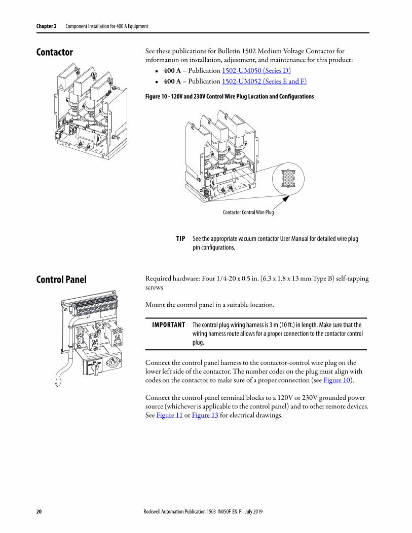
Contactor See these publications for Bulletin 1502 Medium Voltage Contactor for information on installation, adjustment, and maintenance for this product:
• 400 A – Publication 1502-UM050 (Series D)• 400 A – Publication 1502-UM052 (Series E and F)
Figure 10 - 120V and 230V Control Wire Plug Location and Configurations
Control Panel Required hardware: Four 1/4-20 x 0.5 in. (6.3 x 1.8 x 13 mm Type B) self-tapping screws
Mount the control panel in a suitable location.
Connect the control panel harness to the contactor-control wire plug on the lower left side of the contactor. The number codes on the plug must align with codes on the contactor to make sure of a proper connection (see Figure 10).
Connect the control-panel terminal blocks to a 120V or 230V grounded power source (whichever is applicable to the control panel) and to other remote devices. See Figure 11 or Figure 13 for electrical drawings.
TIP See the appropriate vacuum contactor User Manual for detailed wire plug pin configurations.
Contactor Control Wire Plug
IMPORTANT The control plug wiring harness is 3 m (10 ft.) in length. Make sure that the wiring harness route allows for a proper connection to the contactor control plug.
20 Rockwell Automation Publication 1503-IN050F-EN-P - July 2019

Component Installation for 400 A Equipment Chapter 2
Figure 11 - Typical Schematic Diagram for 400 A Full-voltage Non-reversing (FVNR) Controller with Electromechanical Control and Electrically Held Contactor, 120V AC (Normal Drop-out Time)
Main
Cont
acto
r (M
)
CC -
Closin
g Coil
HC- H
olding
Coil
Rem
ove J
umpe
r whe
n con
necti
ng re
mot
e equ
ipmen
t.Re
mot
e Equ
ipmen
t.Lo
w vo
ltage
door
-mou
nted
devic
e.‘IE
EE’ n
umbe
r for
prot
ectiv
e dev
ice.
Met
al ox
ide Va
risto
r.
Econ
omizi
ng
Cont
acto
r (CR
2)
Main
Cont
acto
r Pilo
t Re
lay (C
R1)
Extra
Auxil
iary C
onta
cts
Test
Supp
ly
Norm
alTe
stOF
F
Powe
r Bus
GRD
Bus
Isolat
ion Sw
itch (
IS)
Door
Inte
rlock
Curre
nt Li
miti
ngPo
wer F
uses
Curre
nt Li
miti
ngPr
imar
y Fus
es Over
loa
Sto
Star
tSt
art
Run
Off
Recti
fier
Rec/M
ov
Sto
Rockwell Automation Publication 1503-IN050F-EN-P - July 2019 21

Chapter 2 Component Installation for 400 A Equipment
Figure 12 - Typical Schematic Diagram for 400 A Full-voltage Non-reversing (FVNR) Controller with Electromechanical Control and Mechanical Latch Contactor
Extra
Auxil
iary C
onta
cts
Norm
alTe
stOF
F
Powe
r Bus
GRD
Bus
Isolat
ion Sw
itch (
IS)
Door
Inte
rlock
Curre
nt Li
miti
ngPo
wer F
uses
Curre
nt Li
miti
ngPr
imar
y Fus
es Over
loa
Man
ual T
rip
Main
Cont
acto
r
Main
Cont
acto
rLa
tch Re
lay
Test
Supp
ly
Main
Cont
acto
rUn
latch
Relay
Recti
fier
Rec/M
ov
Closin
g Coil
.TC
- Trip
Coil.
Low
volta
ge do
or-m
ount
ed de
vice.
IEEE’
num
ber f
or pr
otec
tive d
evice
.M
etal
oxide
varis
tor.
Note
: See
dim
ensio
n dra
wing
for c
ompo
nent
sizin
g not
sh
own o
n this
draw
ing.
22 Rockwell Automation Publication 1503-IN050F-EN-P - July 2019

Component Installation for 400 A Equipment Chapter 2
Figure 13 - Typical Schematic Diagram for 400 A Full-voltage Non-reversing (FVNR) Controller with IntelliVAC Control and Electrically Held Contactor
Figure 14 - Typical Schematic Diagram for 400 A Full-voltage Non-reversing (FVNR) Controller with IntelliVAC Control and Mechanical Latch Contactor
CCCC
Inte
livac
Not
esOu
tput
Relay
cont
acts
show
n with
out c
ontro
l pow
er ap
plied
. The
se
facto
ry-in
stalle
d con
figur
ation
/pow
er-u
p sta
tes a
re in
effec
t:Co
ntac
tor S
tatu
s - FA
IL-SA
FEM
odule
Stat
us -
FAIL-
SAFE
Inte
lliVAC
to be
prog
ram
med
/conf
igure
d by t
he cu
stom
er be
fore
star
t up.
Rem
ove J
umpe
r whe
n con
necti
ng re
mot
e equ
ipmen
t.Re
mot
e Equ
ipmen
tRe
mot
e Equ
ipmen
tLo
w Vo
ltage
door
-mou
nted
devic
eIEE
E num
ber f
or pr
otec
tive d
evice
Custo
mer
wiri
ng
See d
imen
sion d
rawi
ng fo
r com
pone
nt si
zing n
ot sh
own i
n this
draw
ing.
Main
Cont
acto
r
Test
Supp
ly Po
int
Cont
acto
r Sta
tus
Isolat
ion Sw
itch
GRD
Bus
Powe
r Bus
Door
Inte
rlock
Curre
nt Li
miti
ngPo
wer f
uses
Curre
nt Li
miti
ngPr
imar
y fus
es
Extra
Auxil
iary C
onta
cts
OLOv
erloa
d
Run
Off
Rockwell Automation Publication 1503-IN050F-EN-P - July 2019 23

Chapter 2 Component Installation for 400 A Equipment
Inte
lliVAC
Not
esOu
tput
Relay
Cont
acts
that
are s
hown
with
out c
ontro
l pow
er ap
plied
. The
fo
llowi
ng fa
ctory
-insta
lled c
onfig
urat
ion/p
ower
-up s
tate
s are
in ef
fect.
Cont
acto
r Sta
tus -
Fail S
afe
Mod
ule St
atus
- Fa
il Safe
Inte
lliVAC
to be
prog
ram
med
/conf
igure
d by c
usto
mer
befo
re st
art-u
p.Clo
sing C
oilTC
- Trip
Coil
Low
Volta
ge D
oor M
ount
ed D
evice
IEEE N
umbe
r for
Prot
ectiv
e Dev
iceM
etal
Oxide
Varis
tor
Custo
mer
Wiri
ngSe
e Dim
ensio
n Dra
wing
for c
ompo
nent
sizin
g not
show
n on t
his dr
awin
g
Extra
Auxil
iary C
onta
cts
Powe
r Bus
Isolat
ion Sw
itch
Curre
nt Li
miti
ng Po
wer S
witch
es
GRD
Bus
Door
Inte
rlock
Curre
nt lim
iting
Pr
imar
y fus
es
Main
Cont
acto
r
Test
Supp
ly Po
int
Norm
alTe
stOf
f
Off
Run
Man
ual
Trip
OLOv
erloa
d
24 Rockwell Automation Publication 1503-IN050F-EN-P - July 2019

Component Installation for 400 A Equipment Chapter 2
Door Interlock Assembly The door interlock assembly (see Figure 14), when used with the isolation switch, provides these interlocking features:
• When the isolation switch handle is in the ON position, a pin on the handle overlaps the Z-clip to help prevent the door from being opened.
• When the door is closed and the isolation switch handle is in the ON position, a cover catch inside the door is held in place by the interlock defeater lever. This feature provides another means for holding the door closed while the unit is energized.
Figure 15 - Door Interlock Assembly
1. Mount the door interlock assembly. See Figure 16 for the dimensions.
ATTENTION: The door interlock assembly must be installed for the isolation switch handle to restrict access to the medium-voltage cell while the unit is energized. The isolation switch handle alone does not provide safety interlocking. If the door interlock assembly is not installed, the OEM assumes the responsibility for providing a means to isolate the medium-voltage power cell while the unit is energized. Failure to install a medium-voltage power cell isolation means can expose personnel to medium-voltage that can cause severe burns, injury, or death.
Rear Door Surface
Cover Catchmounting-bracket
Door Flange
Z-clip
Cover Catch
IMPORTANT All mounting hardware for the door interlock assembly is supplied. Metric equivalents are provided if you wish to substitute metric hardware.
Rockwell Automation Publication 1503-IN050F-EN-P - July 2019 25

Chapter 2 Component Installation for 400 A Equipment
2. Drill two 0.172 in. (4.6 mm) pilot holes on the right side of the door for the Z-clip.
3. Drill two 0.219 in. (5.5 mm) pilot holes on the front of the door for the cover catch mounting-bracket.
Figure 16 - Mounting Locations for Door Interlock Assembly
4. Attach the Z-clip with #10 (4.8 x 1.6 Type B) self-tapping screws, but do not tighten them.
5. Attach the cover catch mounting-bracket with #10-32 x 0.500 (M5 x 0.8) rib-necked carriage screws, lock washers, and hex nuts.
6. Attach the cover catch to the cover catch mounting-bracket with the supplied #10-32 x 0.219 pan-head machine screw.
7. Move the handle to the OFF position. Swing the door closed and inspect the position of the Z-clip in relation to the handle pin.
8. Set the Z-clip so that it is just above the handle pin. Do not set the Z-clip more than 0.125 in. (3 mm) above the pin. Tighten the screws.
9. Close the door and move the isolation switch handle to the ON position. If the handle does not move to the ON position, the cover catch is set too high and is not contacting the defeater lever. Open the door and set the cover catch lower.
10. Verify that the door interlock assembly is functioning properly.
1.95[49]
1.55[39]
3.13[80]
0.35[9]
0.88[22]
0.84[21]
MAX.
2.11[54]MIN.
2 X Ø 0.219 [5.31]
3.38[86]
3.50[89]
0.65[17]
2 X Ø 0.172 [4.09]
Pilot Holes(For rib-neckedCarriage bolts)
Customer Supplied Door
Customer Supplied Structure
Customer Supplied Door
Customer Supplied StructureFRONT VIEW RIGHT SIDE VIEW
Pilot Holes
TOP VIEW
See Figure 4
IMPORTANT The pilot holes in the cover catch are threaded. To avoid damaging the thread, use the hardware that is provided to attach the cover catch to the mounting-bracket.
26 Rockwell Automation Publication 1503-IN050F-EN-P - July 2019

Component Installation for 400 A Equipment Chapter 2
Connecting the Isolation Switch to the Isolation Switch Handle
When properly connected, the isolation switch operating mechanism is designed to provide these safety features:
• Prevent the opening of any medium-voltage door that is interlocked with the mechanism while the handle is in the ON position and the unit is energized.
• Prevent moving the handle to the ON position and providing energy to the unit while the medium-voltage door is open.
• Disengage the contactor from the RUN mode when the handle is moved from the ON to OFF position.
Figure 17 - Handle Mechanism Connection
Perform the handle mechanism connection with the handle in the OFF position. The isolation switch must be in the open position with isolation switch blades rested against the ground bar (see Figure 17).
1. Lengthen or shorten the threaded connecting rod until it aligns with the top hole on the isolation switch operating lever.
2. Insert a clevis pin through the holes and secure it with a cotter pin.
IMPORTANT The mechanical interlock is the primary safety mechanism that helps prevent access to the medium-voltage power cell. The mechanism also helps prevent the isolation switch from being opened or closed while under load (meaning, it is a non-load-break switch). A secondary electrical interlock is intended to disengage the contactor if a mechanical interlock failure occurs. See Isolation Switch Auxiliary Contacts on page 42 for additional information.
Disconnect LeverConnecting Rod
Connection Point(Clevis and Cotter Pin)
Isolation Switch Operating Lever
Right Side View
Rockwell Automation Publication 1503-IN050F-EN-P - July 2019 27

Chapter 2 Component Installation for 400 A Equipment
Connecting the Contactor to the Isolation Switch Handle
When properly connected, the contactor interlock, with the isolation switch handle mechanism safety features:
• Prevent the isolation switch from being opened while the contactor is closed and energized.
• Prevent the contactor from closing if the isolation switch is in an intermediate position (that is at halfway point during adjustment).
• Disengage the contactor if the isolation switch moved to the closed position during a contactor test procedure.
Figure 18 - Contactor Interlock Rod Connection
IMPORTANT Complete all installation procedures before beginning any adjustment procedures described in Chapter 3.
Interlock Lever
Clevis
Contactor Interlock Rod
Contactor Operating Lever
Isolation Switch Operating lever
28 Rockwell Automation Publication 1503-IN050F-EN-P - July 2019

Component Installation for 400 A Equipment Chapter 2
Required hardware: All imperial hardware is supplied.
• Two 1/4 in. (M6) lock washers• Two 1/4 in. (M6) flat washers• Two 1/4-20 in. (M6 x 1.0) hex-head cap screws• One 5/16-18 in. (M8 x 1.25) nylock nut• Two 5/16 in. (M8) hex nuts• One 5/16 in. (M8) lock washer• One contactor operating lever• One 5/16-18 x 20.5 in. (M8 x 1.25 x 521 mm) contactor interlock rod
1. Attach the contactor operating lever to the flat section of the contactor shaft with two 1/4-20 in. (M6 x 1.0) hex-head cap screws with two 1/4 in. (M6) lock washers and two 1/4 in. (M6) flat washers (see Figure 19).
2. From the top of the contactor interlock rod, turn a 5/16–18 in. (M8 x 1.25) hex nut at least 2 in. (50 mm) down the rod. Place one 5/16 in. (M8) lock washer over the nut.
3. Insert a 5/16–18 (M8 x 1.25) hex nut into the clevis of the door interlock lever (see Figure 18).
4. Turn the contactor interlock rod into the nut until approximately 1/2 in. (13 mm) of the lever extends above the nut.
Figure 19 - Connecting the Contactor to Isolation Switch Handle
5. Tighten the bottom nut up to the clevis.
IMPORTANT Metric hardware is not supplied. Metric equivalents are given if you wish to substitute metric hardware
IMPORTANT The contactor operating lever is threaded for the supplied 1/4-20 hex-head cap screws. To substitute metric hardware, drill clearance holes in the contactor operating lever and use M6 x 1.0 hex-head cap screws and nuts to secure the lever to the contactor shaft.
2-1/4-20 (M6 x 1.0) Hex Head Cap Screws)2-1/4 in. (M6) Lock Washers2-1/4 in. (M6) Flat Washers
Contactor Shaft
ContactorInterlock Rod
Nylon ContactorBushing
ContactorOperating Lever
Rockwell Automation Publication 1503-IN050F-EN-P - July 2019 29
Chapter 2 Component Installation for 400 A Equipment
6. Insert the lower end of the rod into the nylon contactor bushing. Turn a 5/16–18 in. (M8 x 1.25) nyloc nut onto the lower end of the rod and tighten it up to the flat of the contactor operating lever.
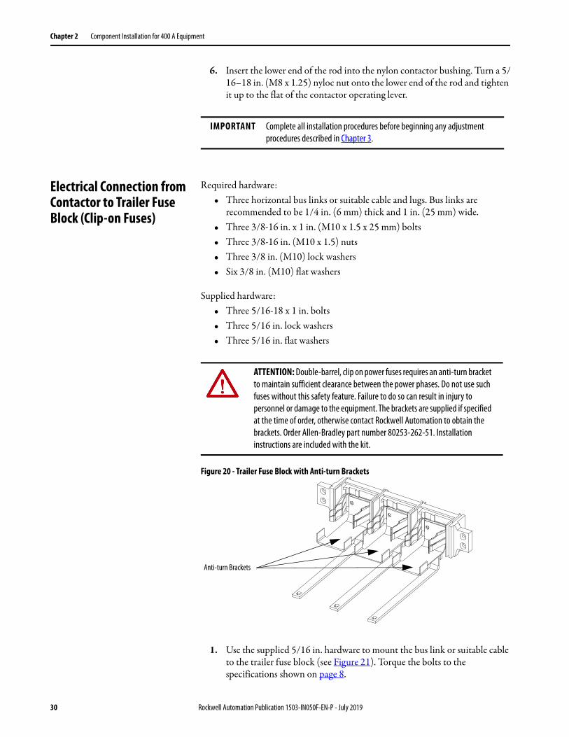
Electrical Connection from Contactor to Trailer Fuse Block (Clip-on Fuses)
Required hardware:• Three horizontal bus links or suitable cable and lugs. Bus links are
recommended to be 1/4 in. (6 mm) thick and 1 in. (25 mm) wide.• Three 3/8-16 in. x 1 in. (M10 x 1.5 x 25 mm) bolts • Three 3/8-16 in. (M10 x 1.5) nuts• Three 3/8 in. (M10) lock washers• Six 3/8 in. (M10) flat washers
Supplied hardware:• Three 5/16-18 x 1 in. bolts• Three 5/16 in. lock washers• Three 5/16 in. flat washers
Figure 20 - Trailer Fuse Block with Anti-turn Brackets
1. Use the supplied 5/16 in. hardware to mount the bus link or suitable cable to the trailer fuse block (see Figure 21). Torque the bolts to the specifications shown on page 8.
IMPORTANT Complete all installation procedures before beginning any adjustment procedures described in Chapter 3.
ATTENTION: Double-barrel, clip on power fuses requires an anti-turn bracket to maintain sufficient clearance between the power phases. Do not use such fuses without this safety feature. Failure to do so can result in injury to personnel or damage to the equipment. The brackets are supplied if specified at the time of order, otherwise contact Rockwell Automation to obtain the brackets. Order Allen-Bradley part number 80253-262-51. Installation instructions are included with the kit.
Anti-turn Brackets
30 Rockwell Automation Publication 1503-IN050F-EN-P - July 2019
Component Installation for 400 A Equipment Chapter 2
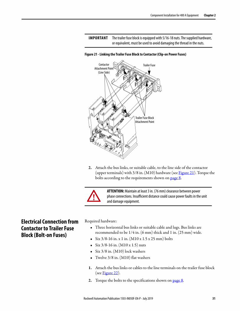
Figure 21 - Linking the Trailer Fuse Block to Contactor (Clip-on Power Fuses)
2. Attach the bus links, or suitable cable, to the line side of the contactor (upper terminals) with 3/8 in. (M10) hardware (see Figure 21). Torque the bolts according to the requirements shown on page 8.
Electrical Connection from Contactor to Trailer Fuse Block (Bolt-on Fuses)
Required hardware:• Three horizontal bus links or suitable cable and lugs. Bus links are
recommended to be 1/4 in. (6 mm) thick and 1 in. (25 mm) wide.• Six 3/8-16 in. x 1 in. (M10 x 1.5 x 25 mm) bolts • Six 3/8-16 in. (M10 x 1.5) nuts• Six 3/8 in. (M10) lock washers• Twelve 3/8 in. (M10) flat washers
1. Attach the bus links or cables to the line terminals on the trailer fuse block (see Figure 22).
2. Torque the bolts to the specifications shown on page 8.
IMPORTANT The trailer fuse block is equipped with 5/16-18 nuts. The supplied hardware, or equivalent, must be used to avoid damaging the thread in the nuts.
Trailer Fuse
Trailer Fuse BlockAttachment Point
ContactorAttachment Point
(Line Side)
ATTENTION: Maintain at least 3 in. (76 mm) clearance between power phase connections. Insufficient distance could cause power faults in the unit and damage equipment.
Rockwell Automation Publication 1503-IN050F-EN-P - July 2019 31

Chapter 2 Component Installation for 400 A Equipment
3. Attach the bus links, or suitable cable, to the line side of the contactor (upper terminals) with 3/8 in. (M10) hardware (see Figure 22).
4. Torque the bolts according to the specifications shown on page 8.
Figure 22 - Linking the Trailer Fuse Block to Contactor (Bolt-on Power Fuses)
Incoming Line Connections Mounting hardware is suitable for use with lugs incorporating two-hole NEMA drilling. Secure incoming cables to line terminals of the isolation switch with suitable lugs and 1/2 in. (M12) hardware. Torque the hardware according to the specifications shown on page 8.
ATTENTION: Maintain at least 3 in. (76 mm) clearance between power phase connections. Insufficient distance could cause power faults in the unit and damage equipment.
Trailer Fuse BlockAttachment Point
ContactorAttachment Point
(Line Side)
Trailer Block Fuse
IMPORTANT Cable size cannot exceed 1-500 or 2-250 MCM per phase.
32 Rockwell Automation Publication 1503-IN050F-EN-P - July 2019

Component Installation for 400 A Equipment Chapter 2
Figure 23 - Isolation Switch Incoming Line Connections (Rear View)
Load Connections Secure load cables to load terminals of contactor with suitable lugs and 3/8 in. (M10) hardware. Torque the hardware according to the specifications shown on page 8.
Figure 24 - Load Terminals - 400 A Contactor (Rear View)
Attach Incoming LineCables Here
IMPORTANT It is your responsibility to determine a suitable means to complete the power connection from the contactor to the motor, which is current transformers, power fuses, and such.
Load Terminals
Rockwell Automation Publication 1503-IN050F-EN-P - July 2019 33

Chapter 2 Component Installation for 400 A Equipment
Connecting the Contactor to the Control Power Transformer
A. Remove the #10-32 hex head screw securing the fuse clips at the front of the contactor (see Figure 25).
Figure 25 - Attaching the Control Power Wires to Contactor (Top View)
2. Attach lugs with a 90° bend (Allen-Bradley part # G6666 – suitable for #12-10 AWG wire) and suitable power wire, use a #10 flat washer and lock washer.
3. Torque the screws to 3.6 N•m (32 lb•in).
4. Fasten the control power transformer cables in position on the contactor with the provided wire clips. This procedure avoids cables from coming into contact with live parts and to meet dielectric test requirements.
IMPORTANT A control power transformer (CPT) is not supplied as part of the OEM starter kit. This procedure only describes how to connect wires to the contactor that supplies power to the control circuit. You are responsible to determine the correct CPT, primary fuse sizes, power wire, lugs, and current transformer for the control circuit.
Remove screws to Mount Lugs
(Front of Contactor)
34 Rockwell Automation Publication 1503-IN050F-EN-P - July 2019

Chapter 3
Adjustments for 400 A Equipment
Door Interlock Circumvention
Some of the following sections require the isolation switch handle to be in the ON position while the medium-voltage door is open. The interlocking safeguards in the mechanism are designed to stop the handle from moving to the ON position while the cabinet door is open.
• To circumvent this safety feature, use a screwdriver, or other tool, to depress the interlock defeater lever in the switch.
• Hold the lever down while moving the handle to the ON (closed) position.
IMPORTANT For proper functionality of the isolation switch assembly, perform the following adjustments in the order they are presented.
ATTENTION: The door interlock mechanism is designed to stop access to the medium-voltage cell while the unit is energized. When the unit is in operation, do not circumvent this interlocking safety feature. Always disconnect and lockout incoming power (See Power Lockout Procedure on page 36) before proceeding with any adjustments that require the handle to be moved to the ON (closed) position. Failure to do so can result in electric shock with severe burns, injury, or death.
Rockwell Automation Publication 1503-IN050F-EN-P - July 2019 35

Chapter 3 Adjustments for 400 A Equipment
Figure 26 - Interlock Defeater Lever
Power Lockout Procedure
1. Disconnect and lockout all feeder power supplies to the starter.
2. Move the isolation switch handle to the OFF position.
3. If the unit is equipped with power factor correction-capacitors, the stored energy must be dissipated before entering the power cell. Wait at least 5 minutes before entering the power cell or dissipate the power with this procedure:a. Verify that the isolation switch handle is in the OFF position. b. Open the low voltage door. c. Plug the appropriate power supply (120V or 230V) into the auxiliary
Power receptacle on the control panel (see Figure 27). d. Move the control switch to the TEST position.
Interlock Defeater Lever
ATTENTION: Always perform the power lockout procedure before servicing the equipment. Use personal protective equipment (PPE) as per local codes or regulations. Failure to do so can result in severe burns, injury, or death.
ATTENTION: The following procedure requires the isolation switch handle to be in the ON position. To avoid shock hazards, disconnect and lockout incoming power before proceeding with the equipment servicing. Failure to lockout incoming power results in a live power cell once the isolation switch handle is in the ON position. The live power cell can cause severe burns, injury, or death. Rockwell Automation® does not assume any responsibility for injuries to personnel who have not completed the following safety procedure before servicing the equipment.
36 Rockwell Automation Publication 1503-IN050F-EN-P - July 2019

Adjustments for 400 A Equipment Chapter 3
Figure 27 - Control Panel (120V Shown)
e. Electrically operate the contactor by pushing the START button on the unit or at a remote location.
f. Disengage the contactor and move the control switch to the NORMAL position. Disconnect the external power supply.
g. Complete the Power Lockout Procedure on page 36. h. Open the medium-voltage door.
4. Visually inspect that the isolation switch blades are in full contact with the grounding pins on the grounding bar. The isolation switch shutters must be closed(see Figure 28).
Figure 28 - Isolation Switch in Open Position
5. Check that the line and load sides of the contactor are voltage free with a hot stick or appropriate voltage measurement device. See Figure 29. a. Check for line-side voltage at the top vacuum-bottle terminals.
Test Switch
Auxiliary Power Receptacle
Grounding Bar
Isolation Switch Shutters must be closed.(Verify for each phase).
Isolation switch blades must be in full contact with the grounding Pins of grounding bar. Verify for each phase.
Rockwell Automation Publication 1503-IN050F-EN-P - July 2019 37

Chapter 3 Adjustments for 400 A Equipment
b. Check for load-side voltage at the bottom vacuum-bottle terminals.
Figure 29 - Contactor Voltage Checkpoints
6. Move the isolation switch handle to the ON position. Use the Door Interlock Circumvention on page 35.
7. Check that the isolation switch blades are voltage free with a hot stick or appropriate voltage measurement device. See Figure 30.
Figure 30 - Isolation Switch Voltage Check Points
8. When all power circuits are verified to be voltage free, move the isolation switch handle back to the OFF position. The unit is now safe to service.
Contactor Interlock Rod Adjustment
1. Complete the Power lockout Procedure (see page 36).
2. Open the medium-voltage door. Use the Door Interlock Circumvention on page 35 to move the isolation switch handle halfway between the OFF and ON position (see Figure 31). Keep the handle in this position until the adjustment procedure is completed.
Check line-side power here.
Check load-side power here.
Isolation Switch Blades must be in fullcontact with Incoming Line Stabs
Check incoming line voltage here
ATTENTION: To avoid shock hazards, lockout incoming power (see page 36) before working on the equipment. Verify with a hot stick or appropriate voltage measurement device that all circuits are voltage free. Failure to do so can result in severe burns, injury, or death.
38 Rockwell Automation Publication 1503-IN050F-EN-P - July 2019

Adjustments for 400 A Equipment Chapter 3
3. With the contactor in the OFF position, insert a 0.050 in. (1.3 mm) feeler gauge in the gap between the interlock lever and the isolation-switch operating lever. The gap must be between 0.045…0.060 in. (1.1…1.5 mm).
4. To reduce the gap distance, follow steps 5…7.
To increase the gap distance, follow steps 8…10.
Figure 31 - Isolation Switch Handle Adjustments
To Reduce the Gap Distance5. Loosen the two screws in the stop bracket and move up the stop bracket
against the interlock lever.
6. With the feeler gauge that is positioned in the gap, move the interlock lever and the stop bracket closer to the isolation-switch operating lever to reduce the gap space. Tighten the stop bracket screws.
7. Tighten the nyloc nut until it is snug against the contactor operating lever. Do not overtighten the nyloc nut as it moves the interlock lever and reduce the gap. Proceed to Step 11.
Isolation Switch Operating Lever
Isolation Switch Handle at Halfway Position
Contactor Operating Lever Nyloc Nut
Gap(0.03. … 0.78 in.)(1.00…2.0 mm)
Contactor Interlock Rod
Interlock Lever
Stop Bracket
Rockwell Automation Publication 1503-IN050F-EN-P - July 2019 39

Chapter 3 Adjustments for 400 A Equipment
To Increase the Gap Distance8. Loosen the two screws in the stop bracket and move the stop bracket away
from the interlock lever.
9. Loosen the nyloc nut until the gap reaches the desired size.
10. Move the stop bracket until it just touches the interlock lever and tighten the screws.
11. Apply Loctite 290 (or equivalent adhesive) to the stop bracket screws and torque the screws to 8 N•m (6 lb•ft).
12. Move the isolation switch handle to the ON position.
13. Manually close the contactor by attaching locking pliers to the contactor operating lever and push down until the armature plate contacts the magnetic cores (see Figure 32).
14. Verify that the interlock lever overlaps the isolation-switch operating lever by at least 0.125 in. (3 mm), see Figure 33.
Figure 32 - Closing the Contactor Manually (Some Parts Not Shown)
Magnetic CoreArmature Plate
40 Rockwell Automation Publication 1503-IN050F-EN-P - July 2019

Adjustments for 400 A Equipment Chapter 3
Figure 33 - Isolation Switch Operating Lever Overlap
15. Open the contactor. Verify that the interlock lever and the rod move freely and that the return springs move the assembly back to the starting position.
Isolation Switch Ground Adjustment
1. Move the isolation switch handle to the OFF position.
2. Inspect the grounding of the isolation switch blades. When the isolation switch handle is in the OFF (open) position, the isolation switch blades must come in full contact with the ground pins of the ground bar. The blades must be within 0.060 in. (1.5 mm) of the ground bar when the handle is in the OFF (open) position (see Figure 34). When the isolation switch handle is in the ON (closed) position, the blades must come in full contact with the line stabs (see Figure 30).
3. To adjust the distance from the blades to the bar, disconnect the threaded connecting rod at the isolation-switch operating lever (see Figure 17 on page 27).
4. Turn the threaded connecting rod to lengthen or shorten it. This adjustment changes the position of the isolation switch blades in the ON and OFF position.
0.125 in. (3 mm)
Interlock Lever
Isolation Switch Operating Lever
ATTENTION: To avoid shock hazards, lockout incoming power before working on the equipment. Verify with a hot stick or appropriate voltage measurement device that all circuits are voltage free. Failure to do so can result in severe burns, injury, or death.
Rockwell Automation Publication 1503-IN050F-EN-P - July 2019 41

Chapter 3 Adjustments for 400 A Equipment
Figure 34 - Isolation Switch Ground Adjustment
Isolation Switch Auxiliary Contacts
The auxiliary contacts are mounted on the left side of the isolation switch, below the cams on the isolation switch shaft.
Normally open contacts (Isolation Switch a Contacts - ISa) are on the outside of the isolation switch housing. Normally closed contacts (Isolation Switch b Contacts - ISb) are on the inside of the housing.
Figure 35 - Location of ISa and ISb Auxiliary Contacts
ISa and ISb contacts are the same (700 CPM). The cam controls the normally open or normally closed status of the contacts.
See Figure 11 on page 21 to Figure 14 on page 23 for the wiring diagrams.
Maximum Gap 1.5 mm (0.060 in.) between Ground Bar and Isolation Switch Blade in open position.
Ground Bar
Auxiliary Contact
Isolation-switch Blade
Incoming-line Stab
ISb Auxiliary Contacts (N.C.)
ISa Auxiliary Contacts (N.O.)
IMPORTANT Complete Isolation Switch Ground Adjustment on page 41 before adjusting the auxiliary contacts for proper synchronization of the assembly.
42 Rockwell Automation Publication 1503-IN050F-EN-P - July 2019

Adjustments for 400 A Equipment Chapter 3
Adjusting the Normally Open (ISa) Contacts
1. Move the isolation switch handle to the ON (closed) position.
2. Loosen the bolt that holds the outside cam to the shaft. Do not loosen the bolt entirely. The cam must not be able to rotate freely on the shaft.
3. Insert a 0.25 in. (6.35 mm) diameter pin into the cam groove between the cam follower and the end of the cam groove.
Figure 36 - Adjusting Auxiliary Contacts (Isa Auxiliary Contact Shown)
4. Adjust the cam on the shaft. The gap from the cam follower to the end of the cam groove must be the width of the pin, 0.25 in. (6.35 mm).
5. Move the isolation switch handle to the OFF (open) position and check that nothing stops the cam from rotating with the shaft.
6. Tighten the bolt that holds the cam to the shaft. Move the isolation switch handle to the ON position. Use the pin to recheck the gap.
7. Verity that auxiliary contact ISa is open when the isolation switch is open. Verify that ISa contact is closed when isolation switch is closed.
Adjusting the Normally Closed (ISb) Contacts
1. Move the isolation switch handle to the OFF (open) position.
2. Loosen the bolt that holds the inside cam to the shaft. Do not loosen the bolt entirely. The cam must not be able to rotate freely on the shaft.
ATTENTION: To avoid shock hazards, lockout incoming power before working on the equipment. Verify with a hot stick appropriate voltage measurement device that all circuits are voltage free. Failure to do so can result in severe burns, injury, or death.
CATALOG NO.700-CPM
SER. A
20 AMP
Gap 0.25 in. (6.35 mm)
Cam
Cam Follower
Auxiliary Contact
Rockwell Automation Publication 1503-IN050F-EN-P - July 2019 43

Chapter 3 Adjustments for 400 A Equipment
3. Insert a 0.25 in. (6.35 mm) diameter pin into the cam groove between the cam follower and the end of the cam groove.
4. Adjust the cam on the shaft. The gap from the cam follower to the end of the cam groove must be the width of the pin, 0.25 in. (6.35 mm).
5. Move the isolation switch handle to the ON (closed) position and check that nothing stops the cam from rotating with the shaft.
6. Tighten the bolt that holds the cam to the shaft. Move the isolation switch handle to the OFF position. Use the pin to recheck the gap.
7. Operate the handle several times, then recheck the 0.25 in. (6.35 mm) clearance between the end of the cam groove and the follower pin for both cams.
8. Verify that auxiliary contact ISb is closed when isolation switch is open. Verify that ISb contact is open when isolation switch is closed.
Adjusting the “Change of State Point”
1. Once the auxiliaries have been adjusted, move the isolation switch handle to the ON position.
2. Connect a conductivity measurement device across the closed auxiliary contacts.
3. Slowly move the isolation switch handle towards the OFF position and observe the point at which the movable isolation-switch blades separate from the incoming line stabs. The auxiliary contacts must change state from the closed to open position before the isolation switch blades lose contact with the incoming line stabs. This change of state stops the isolation switch from being opened while the unit is energized and under load conditions.
4. If the auxiliaries do not change state before the isolation switch opens, adjust the threaded connecting rod as described in Isolation Switch Ground Adjustment on page 41.
IMPORTANT This procedure sets the secondary electrical interlock. When properly adjusted, the electrical interlock is designed to open the control-circuit power connections before the isolation switch opens when the handle is moved to the OFF position.
ATTENTION: The auxiliary contacts must be properly adjusted to avoid opening the isolation switch under load conditions. Improper adjustment can result in damage to the equipment and/or severe burns, injury, or death to personnel.
44 Rockwell Automation Publication 1503-IN050F-EN-P - July 2019

Chapter 4
Commissioning
Hi-pot and Insulation Resistance Test
Insulation integrity must be checked before energizing electrical equipment. Use a high-voltage AC insulation tester or an insulation resistance tester for this test. If an insulation resistance tester is used, a 5000V type is recommended.
Insulation can be tested from phase to phase and from phase to ground. The recommended level for an AC Hi-Pot test is (2 X VLL) volts, where VLL is the rated line-to-line voltage of the power system. The leakage current must be less than 20 mA. Record the result for future comparison testing.
If an insulation resistance tester is used, it must indicate 50 megohms or greater if the unit is isolated from the line and the motor. If the unit is connected to a motor, the insulation resistance tester must indicate 5 megohms or greater.
Vacuum Bottle Integrity Test
See these publications for the procedure to test vacuum bottle integrity of the Bulletin 1502 contactor:
• 400 A – Publication 1502-UM050 (Series D)• 400 A – Publication 1502-UM052 (Series E and F)
These user manuals contain detailed information on installation, adjustment, and maintenance for this product.
ATTENTION: Exercise caution when performing high-voltage tests on the equipment. Failure to do so can result in electric shock, severe burns, injury, or death.
ATTENTION: To avoid shock hazards, lockout incoming power before working on the equipment. Verify with a hot stick or appropriate voltage measurement device that all circuits are voltage free. Failure to do so can result in severe burns, injury, or death.
Rockwell Automation Publication 1503-IN050F-EN-P - July 2019 45

Chapter 4 Commissioning
Preliminary Checklist Contactor Operation
1. Connect the appropriate external power supply (120V or 230V) to the test receptacle in the control panel.
2. Turn the selector switch to the TEST position (see Figure 27 on page 37).
3. Electrically operate the contactor several times.
4. Inspect the armature plate. Verify that it fully contacts the cores (400 A) or yolk plate (800 A).
5. Turn the selector switch back to the OFF position.
6. Disconnect the test power supply.
Electrical Connections
1. Verify the correct power-cable phase sequence and that the connections are tight. See Torque Requirements on page 8.
2. Verify the power fuse ratings and condition.
3. Verify the control fuse ratings and condition.
4. Check that components were not damaged during power cable installation, and that electrical spacings are sufficient.
ATTENTION: To avoid shock hazards, lockout incoming power before working on the equipment. Verify with a hot stick or appropriate voltage measurement device that all circuits are voltage free. Failure to do so can result in severe burns, injury, or death.
46 Rockwell Automation Publication 1503-IN050F-EN-P - July 2019

Commissioning Chapter 4
Final Checks
1. Remove all tools from the cabinet. All tools and hardware that is used during installation and the commission process must be accounted for before the unit is energized.
2. Remove all temporary jumpers and ground devices that are used during the installation procedures.
3. Make sure that all barriers or covers removed during installation have been securely reattached.
4. Close and secure all doors. Verify that all interlocks that are stopping access to medium-voltage power cells are functioning correctly.
5. Restore incoming power from main power supply.
6. Move the isolation switch handle to the ON position.
7. The controller is now ready to supply power to the load.
ATTENTION: Use personal protective equipment (PPE) per local codes or regulations. Failure to do so can result in severe burns, injury, or death.
Rockwell Automation Publication 1503-IN050F-EN-P - July 2019 47

Chapter 4 Commissioning
Notes:
48 Rockwell Automation Publication 1503-IN050F-EN-P - July 2019

Chapter 5
Maintenance
Contactor See these publications for detailed maintenance information on the Bulletin 1502 contactor:
• 400 A – Publication 1502-UM050 (Series D)• 400 A – Publication 1502-UM052 (Series E and F)
These user manuals contain detailed information on installation, adjustment, and maintenance for this product.
Isolation Switch Mechanism Inspection and Lubrication
1. Complete the Power Lockout Procedure on page 36.
2. Open the medium-voltage door.
3. Inspect the condition of the clevis pin and cotter pins that are shown in Figure 37. Replace any worn parts.
IMPORTANT Establish a maintenance and inspection schedule for the equipment. Annually service (or every 20,000 operations – whichever comes first) is the minimum that is recommended; however, extreme operating conditions can warrant additional attention.
ATTENTION: To avoid shock hazards, lockout incoming power (see page 35) before working on the equipment. Verify with a hot stick or appropriate voltage measurement device that all circuits are voltage free. Failure to do so can result in severe burns, injury, or death.
Rockwell Automation Publication 1503-IN050F-EN-P - July 2019 49

Chapter 5 Maintenance
Figure 37 - Isolation Switch Handle Mechanism Lubrication Points
4. If the isolation switch operating lever or the interlock lever is replaced, apply Dow Corning 55 O-ring lubricant (or equivalent) to the pivot points before installing the new components (see Figure 37).
5. Inspect the mounting hardware on the isolation switch operating lever and contactor interlock rod (see Figure 37). Tighten any loose hardware.
6. Inspect the isolation switch blades and the incoming line stabs (see Figure 34 on page 42). The mating surfaces must be clean and lubricated.
7. Remove any dirt and dried grease.
8. Lubricate the isolation switch blades and the pivot points of the isolation switch blades with NyoGel 759G - part number T9327-105 (see Figure 38).
Clevis Pins and Cotter Pins
Interlock Lever
Threaded Connector Rod
Lubrication Points
Contactor Interlock Rod
Isolation Switch Operating Lever
IMPORTANT Do not scrape or file the parts as it can remove the plating and expose the underlying copper to corrosion.
IMPORTANT Lubricate the isolation switch blades a minimum of once per year to avoid excessive wear to the components and to help prevent the isolation switch blades from overheating.
50 Rockwell Automation Publication 1503-IN050F-EN-P - July 2019

Maintenance Chapter 5
Figure 38 - Isolation Switch Lubrication Points
Auxiliary Contacts Inspection and Replacement
1. Move the isolation switch handle to the OFF position and open the controller door.
2. Inspect the auxiliary contacts for wear, scorching, or heat damage. Replace any damaged contacts.
The contacts have a mean time between failure (MTBF) rating of 20 million operations when used within the operating specifications.
3. Remove the contact by turning both of the D-head fasteners until the flat sections are aligned with the edge of the contact (see Figure 39).
4. Remove the contact from the housing.
5. Disconnect the wires from the auxiliary contact.
6. To replace the auxiliary contact, reverse the procedure.
7. Verify that the contact is correctly positioned into the contact carrier (see Figure 39).
Lubricate Isolation Switch Blades
Lubricate Pivot Points
ATTENTION: To avoid shock hazard, lockout incoming power before working on the equipment. Verify with a hot stick or appropriate voltage measurement device that all circuits are voltage free. Failure to do so can result in severe burns, injury, or death.
Rockwell Automation Publication 1503-IN050F-EN-P - July 2019 51

Chapter 5 Maintenance
Figure 39 - Auxiliary Contact Orientation
52 Rockwell Automation Publication 1503-IN050F-EN-P - July 2019

Chapter 6
Spare Parts
Spare Parts Table 1 - Spare Part Numbers
See these publications for information on spare parts for the Bulletin 1502 medium voltage 400 A contactor (120V and 230V):
• 400 A – Publication 1502-UM050 (Series D)• 400 A – Publication 1502-UM052 (Series E and F)
These user manuals contain detailed information on installation, adjustment, and maintenance for this product.
Part Number Description Recommended Stocking Qty.
1503C-E4D Low Voltage Control Panel – 120V AC (1) (2)
(1) The Low Voltage Control Panel includes the following: CR1 relay, CR2 Relay, rectifier, MOV assembly, test switch, test plug. (2) See publication 1503-UM053 for spare part information for IntelliVAC™ control modules.
1
1503C-E4E Low Voltage Control Panel – 230V AC(1) (2) 1
40266-515-03 20 A Isolation Switch Auxiliary Contact (700 CPM) 2
80178-707-53 Isolation Switch Refurbishment Kit – 400 A 1
80154-422-01 Auxiliary Switch Cam Follower 2
80154-542-51 Auxiliary Switch Housing Assembly 2
T9327-105 NyoGel 759G Isolation Switch Lubricant 1
80144-491-02 Fuse Extractor (For Clip-on Power Fuses) 1
Rockwell Automation Publication 1503-IN050F-EN-P - July 2019 53

Chapter 6 Spare Parts
Notes:
54 Rockwell Automation Publication 1503-IN050F-EN-P - July 2019

Appendix A
OEM Kit Chart
OEM Kit ChartTable 2 - Items Included with the Power Cell and Frame
Final Part Number
Qty Description Salable Part Number
Internal Part Number
1503F-E4GCD 1 400 A, 2.3…5.0 kV, electrically held, clip on fuse, electromechanical, 110…120V AC control frame 1503F-E4GCD 80158-951-61
1 Electrically held 120V control panel 1503C-E4D 80158-143-51
1503F-E4GCE 1 400 A, 2.3…5.0 kV, electrically held, clip on fuse, electromechanical, 220…230V AC control frame 1503F-E4GCE 80158-951-65
1 Electrically held 230V control panel 1503C-E4E 80158-143-53
1503F-E4GCU 1 400 A, 2.3…5.0 kV, electrically held, clip on fuse, IntelliVAC, 110…120V AC control frame 1503F-E4GCU 80178-373-58
1 IntelliVAC base 1503VC-BMC5 80178-370-52
1 Wire harness-IntelliVAC 1503-WHE4V 80178-142-57
1503F-E4GBD 1 400 A, 2.3…5.0 kV, electrically held, bolt on fuse, electromechanical, 110…120V AC control frame 1503F-E4GBD 80158-951-59
1 Electrically Held 120V control panel 1503C-E4D 80158-143-51
1503F-E4GBE 1 400 A, 2.3…5.0 kV, electrically held, bolt on fuse, electromechanical, 220…230V AC control frame 1503F-E4GBE 80158-951-63
1 Electrically Held 230V Control Panel 1503C-E4E 80158-143-53
1503F-E4GBU 1 400 A, 2.3…5.0 kV, electrically held, bolt on fuse, IntelliVAC, 110…120V AC control frame 1503F-E4GBU 80178-373-55
1 IntelliVAC base 1503VC-BMC5 80178-370-52
1 Wire harness-IntelliVAC 1503-WHE4V 80158-142-57
1503F-M4GCD 1 400 A, 2.3…5.0 kV, mechanical latch, clip on fuse, electromechanical, 110…120V AC control frame 1503F-M4GCD 80158-951-69
1 Mechanical Latch 120V control panel 1503C-M4D 80158-143-52
1503F-M4GCU 1 400 A, 2.3…5.0 kV, mechanical latch, clip on fuse, IntelliVAC< 110…120V AC control frame 1503F-M4GCU 80178-373-63
1 IntelliVAC base 1503VC-BMC5 80178-370-52
1 Wire harness-IntelliVAC 1503-WHM4V 80158-142-52
1503F-M4GBD 1 400 A, 2.3…5.0 kV, mechanical latch, bolt on fuse, electromechanical, 110…120V AC control frame 1503F-M4GBD 80158-951-67
1 Mechanical latch 120V control panel 1503C-M4D 80158-143-52
1503F-M4GBU 1 400 A, 2.3…5.0 kV, mechanical latch, bolt on fuse, IntelliVAC< 110…120V AC control frame 1503F-M4GBU 80178-373-61
1 IntelliVAC base 1503VC-BMC5 80178-370-52
1 Wire harness – IntelliVAC 1503-WHM4V 80158-142-52
1503F-E4KCD 1 400 A, 5.1…6.9 kV, electrically held, clip on fuse, electromechanical, 110…120V AC control frame 1503F-E4KCD 80158-951-62
1 Electrically held 120V control panel 1503C-E4D 80158-143-51
1503F-E4KCE 1 400 A, 5.1…6.9 kV, electrically held, clip on fuse, electromechanical, 220…230V AC control frame 1503F-E4KCE 80158-951-66
1 Electrically Held 230V control panel 1503C-E4E 80158-143-53
Rockwell Automation Publication 1503-IN050F-EN-P - July 2019 55

Appendix A OEM Kit Chart
1503F-E4KCU 1 400 A, 5.1 …6.9 kV, electrically held, clip on fuse, IntelliVAC, 110…120V AC control frame 1503F-E4KCU 80178-373-68
1 IntelliVAC base 1503VC-BMC5 80178-370-52
Wire harness-IntelliVAC 1503-WHE4V 80158-142-57
1503F-E4KBD 1 400 A, 5.1…6.9 kV, electrically held, bolt on fuse, electromechanical, 110…120V AC control frame 1503F-E4KBD 80158-951-60
1 Electrically held 120V control panel 1503C-E4D 80158-951-51
1503F-E4KBE 1 400 A, 5.1…6.9 kV, electrically held, bolt on fuse, electromechanical, 220…230V AC control frame 1503F-E4KBE 80158-951-64
1 Electrically held 230V control panel 1503C-E4E 80158-143-53
1503F-E4KBU 1 400 A, 5.1…6.9 kV, electrically held, bolt on fuse, IntelliVAC, 110…120 V ACcontrol frame 1503F-E4KBU 80178-373-65
1 IntelliVAC base 1503VC-BMC5 80178-370-52
1 Wire harness-IntelliVAC 1503-WHE4V 80158-142-57
1503F-M4KCD 1 400 A, 5.1…6.9 kV, mechanical latch, clip on fuse, electromechanical, 110…120V AC control frame 1503F-M4KCD 80158-951-70
1 IntelliVAC base 1503C-M4D 80158-143-52
1 Wire harness-IntelliVAC 1503F-M4KCU 80178-373-73
1503-M4KBD 1 400 A, 5.1…6.9 kV, mechanical latch, bolt on fuse, electromechanical, 110…120V AC control frame 1503VC-BMC5 80178-370-52
1 Mechanical latch 120V Control Panel 1503-WHM4V 80158-142-59
1503F-M4KBU 1 400 A, 5.1...6.9 kV, mechanical latch, bolt on fuse, IntelliVAC, 110…120V ACcontrol frame 1503F-M4KBD 80158-951-68
1 IntelliVAC base 1503C-M4D 80158-143-52
1 Wire harness-IntelliVAC 1503-WHM4V 80158-142-59
1503F-E6GBD 1 600 A, 2.3…5.0 kV, electrically held, bolt on fuse, electromechanical, 110…120V ACcontrol frame 1503F-E6GBD 80158-333-57
1 Electrically Held 120V Control Panel 1503FC-E8D 80158-143-54
1503F-E6GBU 1 600 A, 2.3…5.0 kV, electrically held, bolt on fuse, IntelliVAC, 110…120V ACcontrol frame 1503F-E6GBU 80178-374-52
1 IntelliVAC base 1503VC-BMC5 80178-370-52
1 Wire harness-IntelliVAC 1503-WHE8V 80178-142-58
1503F-M6GBD 1 600 A, 2.3…5.0 kV, mechanical latch, bolt on fuse, electromechanical, 110…120V ACcontrol frame 1503F-M6GBD 80158-333-60
1 Mechanical latch 120V control panel 1503C-M8D 80158-143-60
1503F-M6GBU 1 600 A, 2.3…5.0 kV, mechanical latch, bolt on fuse, IntelliVAC 110…120V AC control frame 1503F-M6GBU 80178-374-55
1 IntelliVAC base 1503VC-BMC5 80178-370-52
1 Wire harness-IntelliVAC 1503-WHM8D 80158-142-55
1503F-E6KBD 1 600 A, 5.1…6.9 kV, electrically held, bolt on fuse, electromechanical, 110…120V AC control frame 1503F-E6KBD 80158-333-58
1 Electrically held 120V control panel 1503C-E8D 80158-143-54
1503F-E6KBU 1 600 A, 5.1…6.9 kV, electrically held, bolt on fuse, IntelliVAC, 110…120V AC control frame 1503F-E6KBU 80178-374-57
1 IntelliVAC base 1503VC-BMC5 80178-370-52
1 Wire harness-IntelliVAC 1503-WHE8V 80158-142-58
1503F-M6KBD 1 600 A, 5.1…6.9 kV, mechanical latch, bolt on fuse, electromechanical, 110…120V ACcontrol frame 1503F-M6KBD 80158-333-61
1 Mechanical latch 120V control panel 1503C-M8D 80158-143-55
1503F-M6KBU 1 600 A, 5.1…6.9 kV, mechanical latch, bolt 110…120On Fuse, IntelliVAC 110…120V AC control frame 1503F-M6KBU 80178-374-60
1 IntelliVAC base 1503VC-BMC5 80178-370-52
1 Wire harness-IntelliVAC 1503-WHM8D 80158-142-55
Table 2 - Items Included with the Power Cell and Frame (Continued)
Final Part Number
Qty Description Salable Part Number
Internal Part Number
56 Rockwell Automation Publication 1503-IN050F-EN-P - July 2019


Publication 1503-IN050F-EN-P - July 2019 Supersedes Publication 1503-IN050E-EN-P - June 2013 Copyright © 2019 Rockwell Automation, Inc. All rights reserved. Printed in Canada.
Rockwell Automation Support
Use the following resources to access support information.
Documentation Feedback
Your comments will help us serve your documentation needs better. If you have any suggestions on how to improve this document, complete the How Are We Doing? form at http://literature.rockwellautomation.com/idc/groups/literature/documents/du/ra-du002_-en-e.pdf.
Technical Support Center Knowledgebase Articles, How-to Videos, FAQs, Chat, User Forums, and Product Notification Updates.
https://rockwellautomation.custhelp.com/
Local Technical Support Phone Numbers
Locate the phone number for your country. http://www.rockwellautomation.com/global/support/get-support-now.page
Direct Dial Codes Find the Direct Dial Code for your product. Use the code to route your call directly to a technical support engineer.
http://www.rockwellautomation.com/global/support/direct-dial.page
Literature Library Installation Instructions, Manuals, Brochures, and Technical Data.
http://www.rockwellautomation.com/global/literature-library/overview.page
Product Compatibility and Download Center (PCDC)
Get help determining how products interact, check features and capabilities, and find associated firmware.
http://www.rockwellautomation.com/global/support/pcdc.page
.
Rockwell Otomasyon Ticaret A.Ş., Kar Plaza İş Merkezi E Blok Kat:6 34752 İçerenköy, İstanbul, Tel: +90 (216) 5698400
Rockwell Automation maintains current product environmental information on its website at http://www.rockwellautomation.com/rockwellautomation/about-us/sustainability-ethics/product-environmental-compliance.page.
Allen-Bradley, IntelliVAC, Rockwell Automation, and Rockwell Software are trademarks of Rockwell Automation, Inc.
Trademarks not belonging to Rockwell Automation are property of their respective companies.
Top Related