


Languages
Pages
Legal

NSC Quality Engineering Seminar
Workmanship Standards
Jeannette PlanteNASA Workmanship Program Manager
February 14, 2011
11/13/2009 1

The purpose of this seminar is to familiarize you with the Workmanship Standards so that you can:
• Be an advocate for their use in the manufacture of NASA mission hardware
• Have insight about how they are intended to be used
Seminar Organization
In this seminar, we’ll cover the basics of
Workmanship Standards, including:• Terms and Definitions• Fundamental intent and value added• Policy authority• Common requirements• Examples of technical requirements• Electrostatic Discharge Control requirements
2
Welcome
3
Suggested Periods for Clandestine Blackberry Usage
0
1
2
3
4
5
6
7
8
9
10
20 40 60 80 100 120
Imp
ort
an
ce
Time (minutes)
typical message importance
typical blackberry use
today's message importance
suggested blackberry use
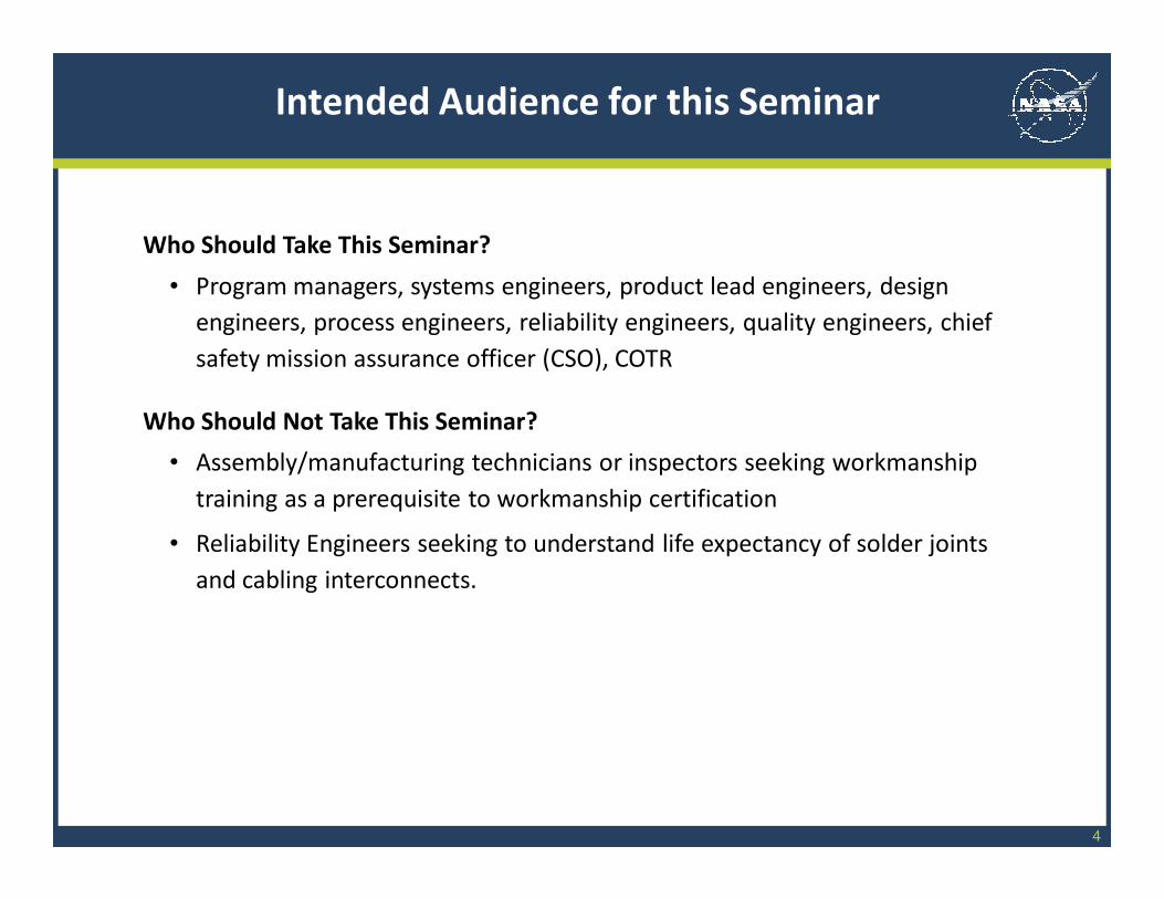
Who Should Take This Seminar?
• Program managers, systems engineers, product lead engineers, design
engineers, process engineers, reliability engineers, quality engineers, chief
safety mission assurance officer (CSO), COTR
Who Should Not Take This Seminar?
• Assembly/manufacturing technicians or inspectors seeking workmanship
training as a prerequisite to workmanship certification
• Reliability Engineers seeking to understand life expectancy of solder joints
and cabling interconnects.
4
Intended Audience for this Seminar
5
Materials and configurations named in the Workmanship Standards are
considered technologically standard and have demonstrated high reliability
for a broad range of NASA missions and thus are mature.
The Workmanship Standards specify design, processing, and inspection
requirements, which are relevant to the materials and configurations
named, which ensure high quality hardware is supplied.
Suppliers are expected to perform manufacturing using controlled
processes, which operators implement using established procedures, and
which results in a product that is compliant with the Workmanship
requirements.
Suppliers who use configurations and materials not named in the
Workmanship Standards must establish that the resulting hardware will be
reliable for the applicable mission and must establish, declare, and use
relevant design, processing, and inspection requirements to assure that
the final items have high quality.
Basic Assumptions of the Workmanship Standards Program
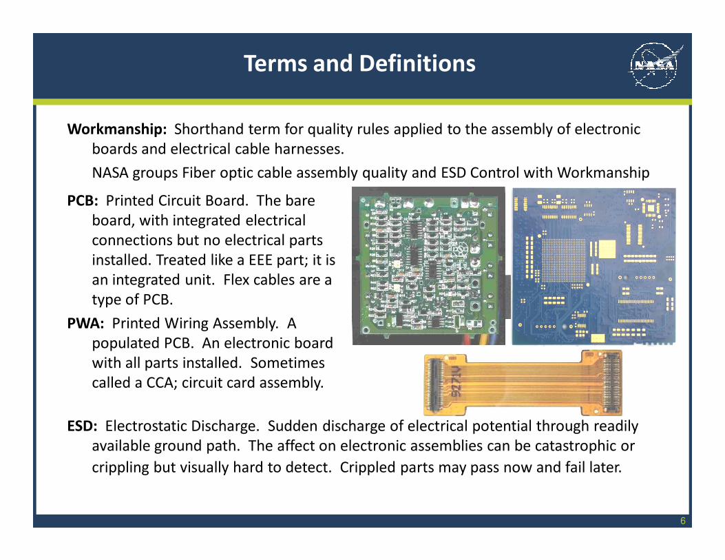
Workmanship: Shorthand term for quality rules applied to the assembly of electronic
boards and electrical cable harnesses.
NASA groups Fiber optic cable assembly quality and ESD Control with Workmanship
6
PCB: Printed Circuit Board. The bare
board, with integrated electrical
connections but no electrical parts
installed. Treated like a EEE part; it is
an integrated unit. Flex cables are a
type of PCB.
PWA: Printed Wiring Assembly. A
populated PCB. An electronic board
with all parts installed. Sometimes
called a CCA; circuit card assembly.
ESD: Electrostatic Discharge. Sudden discharge of electrical potential through readily
available ground path. The affect on electronic assemblies can be catastrophic or
crippling but visually hard to detect. Crippled parts may pass now and fail later.
Terms and Definitions
Solder: Low melt-temperature metal alloy used to provide a conductive, long lasting
connection between an electrical part lead and the pad of the printed circuit board
or between a wire and a connector contact. 63% Tin (Sn) + 37% Lead (Pb) is
standard for electronics.
7
Flux: Acid-containing material (organic or
inorganic acid) used to remove oxide and
residues from soldered surfaces thereby
allowing the solder joint to readily form.
Staking: Polymeric material used to
mechanically tack-bond part bodies to
the PCB surface.
Conformal Coating: Polymeric material used
to thinly coat a PWA to protect it from
“bumps and bruises” and conductive
debris. Will also retard surface corrosion
of PWA exposed metal surfaces.
Terms and Definitions
8
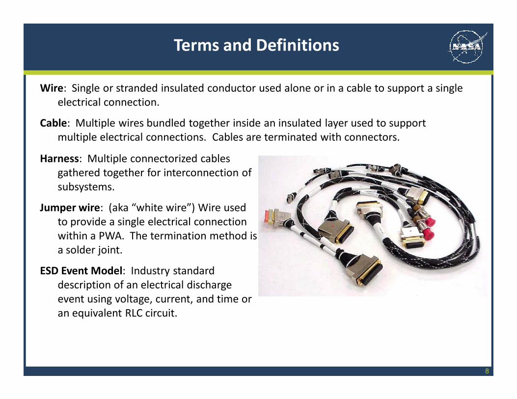
Harness: Multiple connectorized cables
gathered together for interconnection of
subsystems.
Jumper wire: (aka “white wire”) Wire used
to provide a single electrical connection
within a PWA. The termination method is
a solder joint.
ESD Event Model: Industry standard
description of an electrical discharge
event using voltage, current, and time or
an equivalent RLC circuit.
Wire: Single or stranded insulated conductor used alone or in a cable to support a single
electrical connection.
Cable: Multiple wires bundled together inside an insulated layer used to support
multiple electrical connections. Cables are terminated with connectors.
Terms and Definitions
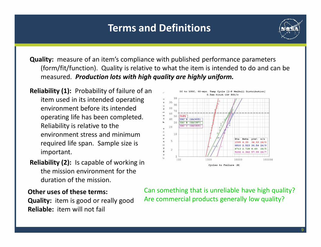
Quality: measure of an item’s compliance with published performance parameters
(form/fit/function). Quality is relative to what the item is intended to do and can be
measured. Production lots with high quality are highly uniform.
9
Reliability (1): Probability of failure of an
item used in its intended operating
environment before its intended
operating life has been completed.
Reliability is relative to the
environment stress and minimum
required life span. Sample size is
important.
Reliability (2): Is capable of working in
the mission environment for the
duration of the mission.
Can something that is unreliable have high quality?
Are commercial products generally low quality?
Terms and Definitions
Other uses of these terms:
Quality: item is good or really good
Reliable: item will not fail
10
Qualified or Qualification
Process Qualification: Quality parameters have been identified, are controlled, and are
monitored to ensure that (a) un-screenable defects are not produced in the final
item, (b) every item produced has identical quality, (c) scrap is minimized.
Prototype runs and destructive tests are used to achieve (a) above. Non-destructive
in-line and end-of-line tests and inspections are used to achieve (b) above. Process
Qualification ensures that the manufacturing recipe “works”.
Product Qualification: Destructive testing used to (a) identify relevant screening tests to
achieve high and uniform quality and to (b) demonstrate the capability of the
finished item to perform as intended in the application environment for the duration
intended. “Generic” qualification test flows may use very wide temperature ranges
(e.g. mil-spec) and durations that test to failure. Mission-specific qualification test
conditions may not be applicable to other missions (Qualification by Heritage).
Product Qualification ensures that the design+manufacturing+screening = a part
that is not likely to fail in the mission.
There is no NASA standard definition for Space Qualified. This is a marketing term.
Terms and Definitions
11
Design Requirements: Controls materials and configurations (e.g. dimensions,
placement, interface materials) selected to provide operational performance.
Workmanship Examples: Solder material, flux material, staking of wire runs to enable
performance in shock/vibration environment.
Processing Requirements: Controls the manufacturing methods or techniques.
Workmanship Examples: Use of certain type of container to mix polymers to avoid
contaminating the polymer, periodic alloy check of solder pot to ensure material
purity, control of environmental conditions such as humidity
Defect Criteria (aka accept/reject criteria, quality criteria): Physical attributes that are
evidence of a defect or known to be indicative of the presence of a defect that will
result in premature failure.
Workmanship Examples: solder joint appearance, presence of extraneous material,
nicks and scrapes in conductors, missing material, delaminated material.
Training and Certification of Operators, Inspectors, and Instructors
NASA Workmanship Requirements Categories
12
Procedure or Requirements Document
Procedure: Step-by-step instructions for implementing a manufacturing
process. Procedures will include steps that ensure that quality requirements
are met. These steps may include use of special fixtures, checking
temperature, ESD wrist strap check, in-process measurements, and end-
point tests and inspections.
Requirement Document: Collection of requirement with applicable scope and
intended requirements owners. May include accept/reject/defect criteria.
Workmanship Standards are Requirements Documents
Terms and Definitions
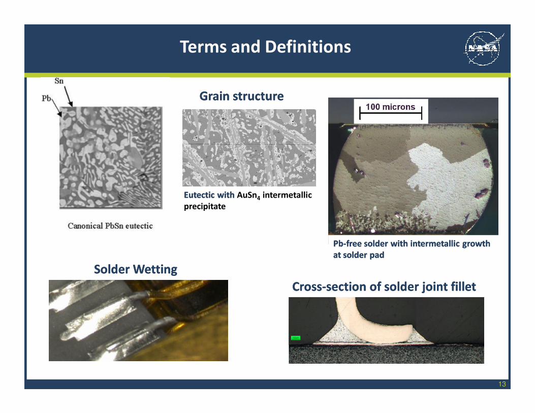
13
CrossCross--section of solder joint filletsection of solder joint fillet
Grain structureGrain structure
Terms and Definitions
Solder Solder WettingWetting
Eutectic with Eutectic with AuSn4 intermetallic
precipitate
PbPb--free solder with intermetallic growth free solder with intermetallic growth
at solder padat solder pad
14
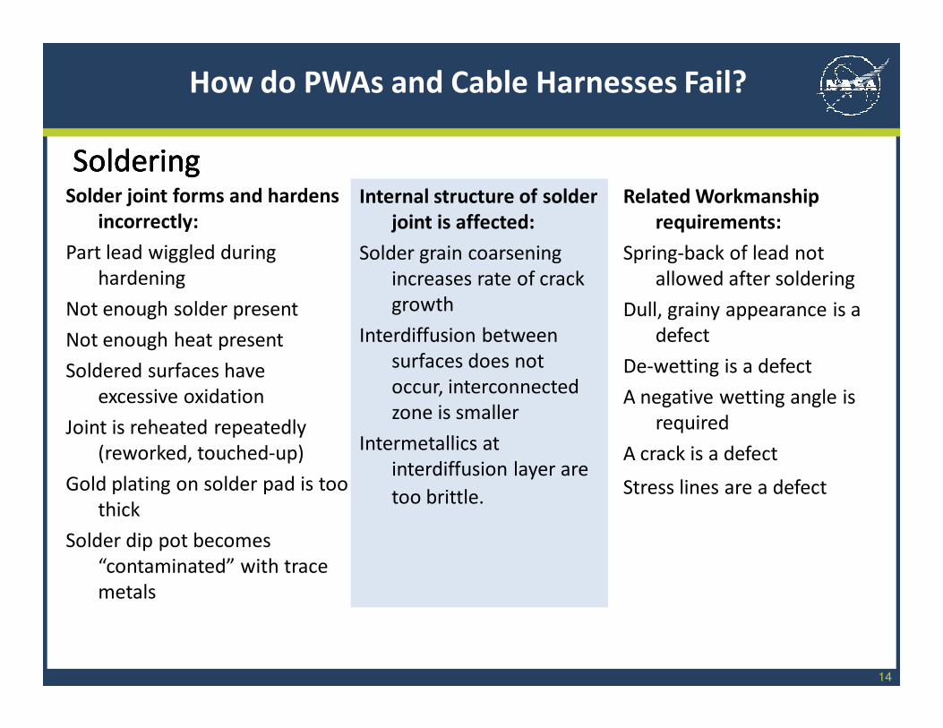
Related Workmanship
requirements:
Spring-back of lead not
allowed after soldering
Dull, grainy appearance is a
defect
De-wetting is a defect
A negative wetting angle is
required
A crack is a defect
Stress lines are a defect
How do PWAs and Cable Harnesses Fail?
Internal structure of solder
joint is affected:
Solder grain coarsening
increases rate of crack
growth
Interdiffusion between
surfaces does not
occur, interconnected
zone is smaller
Intermetallics at
interdiffusion layer are
too brittle.
Solder joint forms and hardens
incorrectly:
Part lead wiggled during
hardening
Not enough solder present
Not enough heat present
Soldered surfaces have
excessive oxidation
Joint is reheated repeatedly
(reworked, touched-up)
Gold plating on solder pad is too
thick
Solder dip pot becomes
“contaminated” with trace
metals
SolderingSolderingSolderingSoldering
15
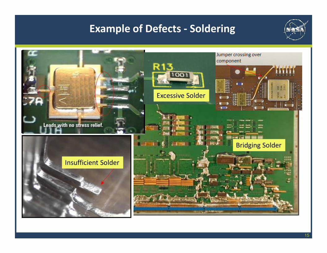
Example of Defects - Soldering
Insufficient Solder
Excessive Solder
Bridging Solder
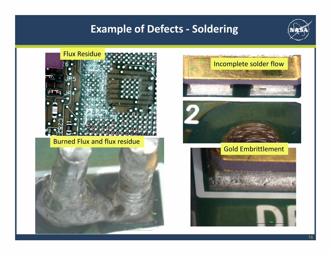
16
Burned Flux and flux residue
Incomplete solder flow
Gold Embrittlement
Example of Defects - Soldering
Flux Residue
17
Related Workmanship
requirements:
Thickness requirements are
defined
Full and adhered coverage
is required
The amount of voiding
allowed (bubbles) is
limited and defined
How do PWAs and Cable Harnesses Fail?
Performance Impact:
Polymer expands and
overstresses solder
joints
Part lead is exposed to
shorting hazard
Moisture sink is created at
delamination driving up
risk of corrosion.
Material may contain
trapped ionics which
cause low resistance
shorts across surface
Physical Feature:
Thickness build up under part
packages
Thinning at sharp edges
Lack of adhesion to surfaces
Bubbles formed throughout
cured material
Conformal CoatingConformal CoatingConformal CoatingConformal Coating
18
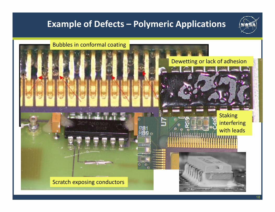
Example of Defects – Polymeric Applications
Bubbles in conformal coating
Scratch exposing conductors
Dewetting or lack of adhesion
Staking
interfering
with leads
19
Related Workmanship
requirements:
Exposed copper not allowed
on wire
Limits set on number of
broken strands
Crimping calibration and in-
process quality metric
required prior to
production
Staggering of splices
required
Pin seating testing required
How do PWAs and Cable Harnesses Fail?
Performance Impact:
Wire conductor can corrode
and fail electrically and/or
mechanically
Crimp connection weakens
and fails
Backshell doesn’t fit, rework
forces increased stress on
harness
Contact backs out of place
and connection fails
Physical Feature:
Bare conductor wire is
nicked exposing bare
copper
Too many wire strands are
broken
Crack in contact crimp barrel
Splicing behind connector
not staggered
Connector pin not fully
seated
HarnessesHarnessesHarnessesHarnesses
20
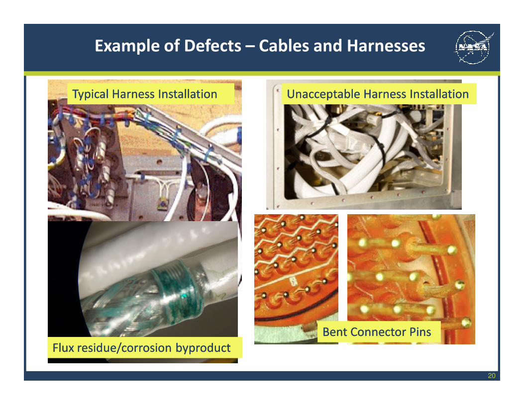
Typical Harness InstallationTypical Harness InstallationTypical Harness InstallationTypical Harness Installation Unacceptable Harness InstallationUnacceptable Harness InstallationUnacceptable Harness InstallationUnacceptable Harness Installation
Flux residue/corrosion byproductFlux residue/corrosion byproductFlux residue/corrosion byproductFlux residue/corrosion byproduct
Bent Connector PinsBent Connector PinsBent Connector PinsBent Connector Pins
Example of Defects – Cables and Harnesses
21
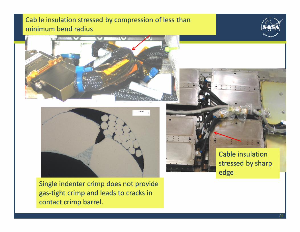
Cab le insulation stressed by compression of less thanCab le insulation stressed by compression of less than
minimum bend radiusminimum bend radius
Cab le insulation stressed by compression of less thanCab le insulation stressed by compression of less than
minimum bend radiusminimum bend radius
Cable insulation Cable insulation
stressed by sharp stressed by sharp
edgeedge
Cable insulation Cable insulation
stressed by sharp stressed by sharp
edgeedge
Single indenter crimp does not provide Single indenter crimp does not provide
gasgas--tight crimp and leads to cracks in tight crimp and leads to cracks in
contact crimp barrel.contact crimp barrel.
Single indenter crimp does not provide Single indenter crimp does not provide
gasgas--tight crimp and leads to cracks in tight crimp and leads to cracks in
contact crimp barrel.contact crimp barrel.
22
Will assemblies with Workmanship defects necessarily fail?
• Use of the materials and configurations in the Workmanship Standards and compliance
to the Workmanship requirements provides excellent assurance that the hardware
remain functional in missions which operate in mil-spec type environments
(temperature, shock/vibe, humidity) for 15 years. This may not be the case for
environment extremes (cryogenic) and very long durations (>20 years).
• Some Workmanship defects have been demonstrated to be associated with shorter
service life through use and test. Some are from lessons learned feedback. Some are
based on “best NASA practice”.
• Use of Workmanship requirements criteria for non-standard, new technology may not be
technically value-added or improve assembly reliability.
Workmanship requirements are better at:
• Pointing out production lines which have not “mastered” the use of a mature
interconnect technology.
• Reducing quality problems at a low level of assembly where it is less expensive to
rework/repair.
Workmanship: Quality vs Reliability
23
Rework: process hardware to be in accordance with the drawing to correct a
quality defect.
• Existing wording in NASA standards is awkward, mentions process allowed. Improved
wording in J-STD-001ES
• Too much rework can reduce reliability. Care must be used to avoid unnecessary
soldering touch-ups and part removals.
• Rework processes must be pre-defined to ensure too much is not normally allowed
• Must be recorded for process engineering feedback. Rework history may be reviewed if
repair is needed.
Repair: resolve a quality defect by using a configuration that is not on the original
drawing.
• May introduce non-standard configurations and materials
• May introduce collateral effects such as stress on nearby interconnects or parts
• Must be reviewed and approved prior to use
Rework vs. Repair
24
Standard vs. Non-Standard Technologies
Standard Technologies:
• Do not require special approval prior to use
• Standard Workmanship rules apply
• Examples:• Wire terminals (soldered to boards, wires soldered to them)
• Surface mount solder joints: chips (0603 size and larger), gull wing
• Through hole joints for DIP packages, and radial leaded and axial leaded two-connection
packages
• Conformal coating with uralane or parylene
• Staking of tantalum capacitors and wire runs
• Using cable ties
• Electrical check-out of harness assembly
• Rosin flux and 63/39 Sn-Pb solder
• Mil-spec connectors: 38999 (circular), 39012 (RF), 24308 (mini-D), 83513 (micro-D)
• Mil-spec wire and cable
• Wire-to-wire splicing
25
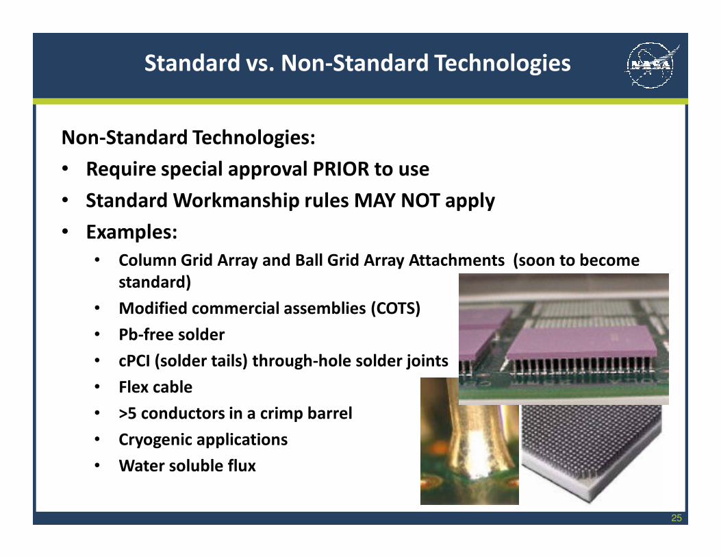
Non-Standard Technologies:
• Require special approval PRIOR to use
• Standard Workmanship rules MAY NOT apply
• Examples:
• Column Grid Array and Ball Grid Array Attachments (soon to become
standard)
• Modified commercial assemblies (COTS)
• Pb-free solder
• cPCI (solder tails) through-hole solder joints
• Flex cable
• >5 conductors in a crimp barrel
• Cryogenic applications
• Water soluble flux
Standard vs. Non-Standard Technologies
26
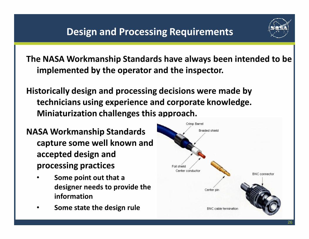
The NASA Workmanship Standards have always been intended to be
implemented by the operator and the inspector.
Historically design and processing decisions were made by
technicians using experience and corporate knowledge.
Miniaturization challenges this approach.
Design and Processing Requirements
NASA Workmanship Standards
capture some well known and
accepted design and
processing practices
• Some point out that a
designer needs to provide the
information
• Some state the design rule
27
Trend in the Workmanship Standards is to eliminate design
requirements and avoid dictating process development
Workmanship Standards trending toward operator and inspector
requirements only
Examples of design requirements being eliminated:
• High strength copper alloy is required for wires gauge 24 and
smaller.
• Line voltages shall be limited to socket contacts (for safety).
• Materials to meet NASA-Std-6001, flammability, odor,
offgassing
• Design of harnesses shall minimize RFI/EMI.
Design and Processing Requirements

28
Examples of “reminders” to designers and process engineers that
will be removed:
• Staking materials and locations must be defined on the
engineering documentation
• Conformal coating material must be defined. Conformal
coating materials with a fluorescent indicator are preferred
• Bond line requirements must be defined.
• Conformal coating maskant material and areas to be masked
on PCBs must be defined
• Demoisturizing conditions for PWAs prior to polymeric
applications (time, temperature, ramp rates) must be defined
• Harness design must plan use of heat-shrinkable sleeving,
stress relief, methods for cable identification, preventing mis-mating of connectors
Design and Processing Requirements
29
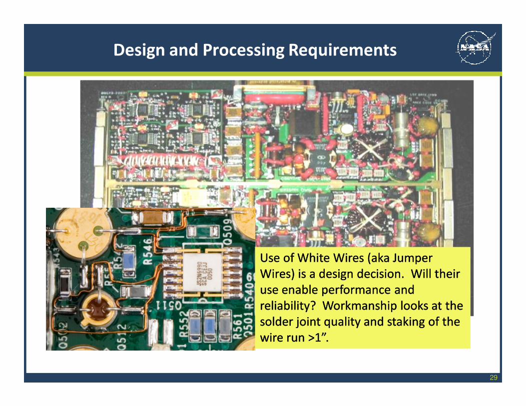
Design and Processing Requirements
Use of WhiteUse of White Wires (aka Jumper Wires (aka Jumper
Wires) is a design decision. Will Wires) is a design decision. Will their their
use enable performance and use enable performance and
reliability? Workmanship looks at the reliability? Workmanship looks at the
solder joint quality and staking of the solder joint quality and staking of the
wire run >1”.wire run >1”.
30
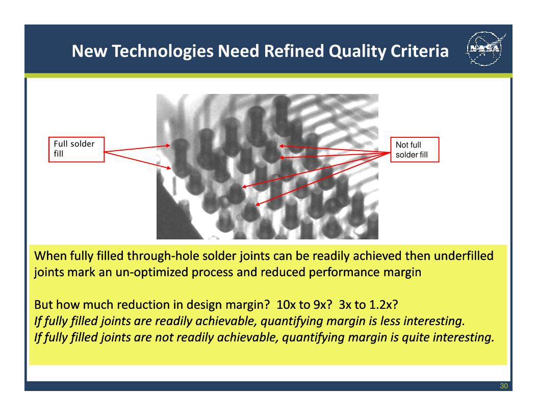
New Technologies Need Refined Quality Criteria
When fully filled throughWhen fully filled through--hole solder joints canhole solder joints can be readily achieved then underfilled be readily achieved then underfilled
joints mark an unjoints mark an un--optimized process and reduced performance marginoptimized process and reduced performance margin
But how much reduction in design margin? 10x to 9x? But how much reduction in design margin? 10x to 9x? 3x to 1.2x?3x to 1.2x?
If fully filled joints are readily achievable, quantifying margin is less interesting.If fully filled joints are readily achievable, quantifying margin is less interesting.
If fully filled joints are not readily achievable, If fully filled joints are not readily achievable, quantifyingquantifying margin is quite interesting.margin is quite interesting.
Not full
solder fill
Full solder
fill
31
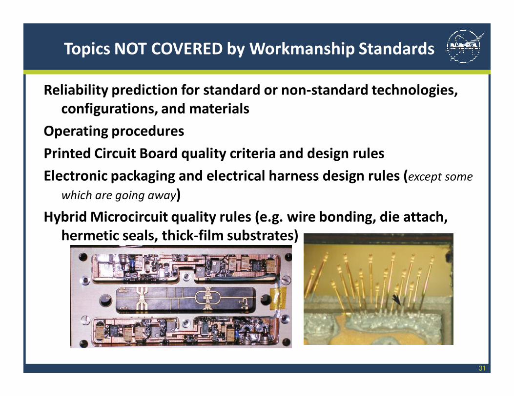
Topics NOT COVERED by Workmanship Standards
Reliability prediction for standard or non-standard technologies,
configurations, and materials
Operating procedures
Printed Circuit Board quality criteria and design rules
Electronic packaging and electrical harness design rules (except some
which are going away)
Hybrid Microcircuit quality rules (e.g. wire bonding, die attach,
hermetic seals, thick-film substrates)
32
Part I Summary
The Workmanship Standards:
are Directed at operators and inspectors
Provide processing instructions (and some design rules)
Provide screening criteria for known defects for standard
technologies, configurations, and materials
Remove units with defects from mission subsystems at a low
level of assembly when it is less expensive to repair.
Require suppliers to seek prior approval for the use of non-standard
technologies, configurations, and materials
Require suppliers to justify use of non-standard technologies,
configurations, and materials with qualification data
Require suppliers to define relevant inspection criteria for non-
standard technologies, configurations, and materials.
33
Part II: Workmanship Program Authority
How does NASA Headquarters provide for a common
Workmanship quality baseline across the Agency?
How does that system maintain the baseline requirements
and promote and explain the information?
Why do we use some NASA
Standards and some
Industry Standards?
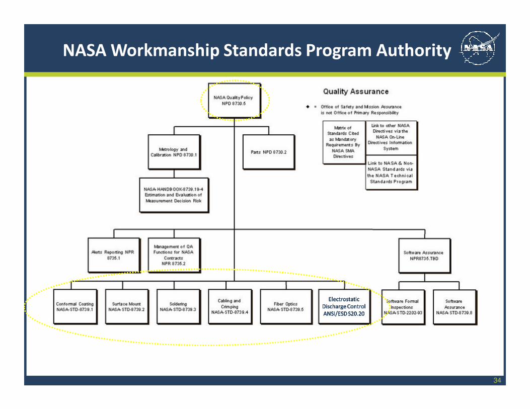
34
ElectrostaticElectrostatic
Discharge ControlDischarge Control
ANSI/ESDANSI/ESD S20.20S20.20
ElectrostaticElectrostatic
Discharge ControlDischarge Control
ANSI/ESDANSI/ESD S20.20S20.20
NASA Workmanship Standards Program Authority
35
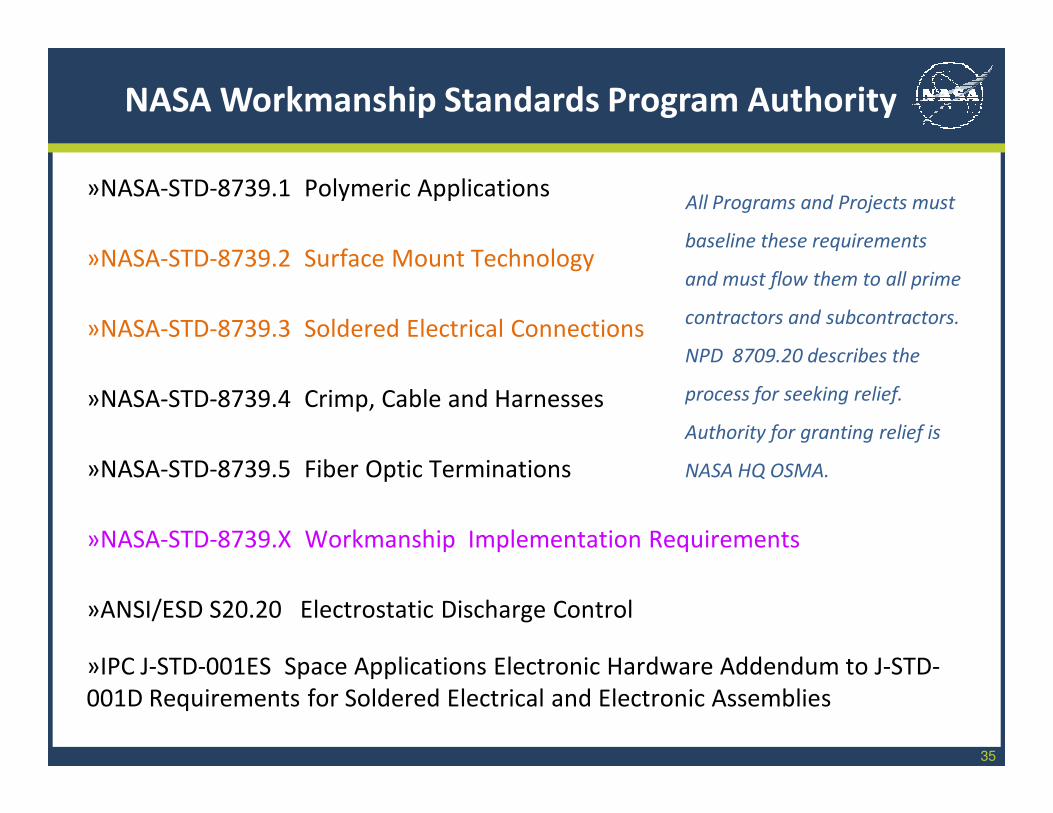
»NASA-STD-8739.1 Polymeric Applications
»NASA-STD-8739.2 Surface Mount Technology
»NASA-STD-8739.3 Soldered Electrical Connections
»NASA-STD-8739.4 Crimp, Cable and Harnesses
»NASA-STD-8739.5 Fiber Optic Terminations
»NASA-STD-8739.X Workmanship Implementation Requirements
»ANSI/ESD S20.20 Electrostatic Discharge Control
»IPC J-STD-001ES Space Applications Electronic Hardware Addendum to J-STD-
001D Requirements for Soldered Electrical and Electronic Assemblies
NASA Workmanship Standards Program Authority
All Programs and Projects must
baseline these requirements
and must flow them to all prime
contractors and subcontractors.
NPD 8709.20 describes the
process for seeking relief.
Authority for granting relief is
NASA HQ OSMA.
36
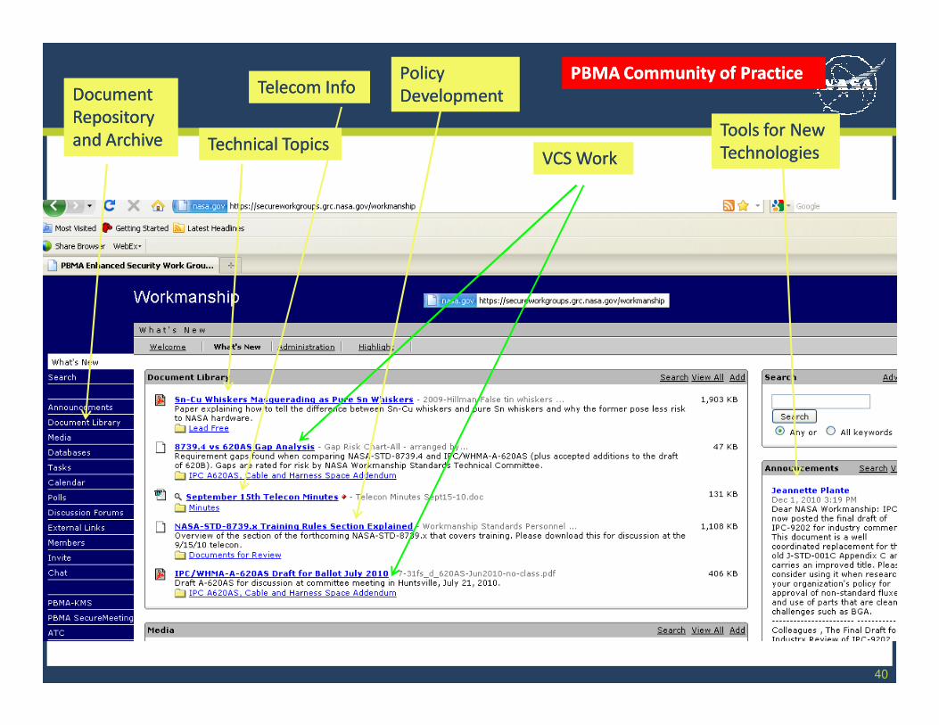
Program CoP Site
https://secureworkgro
ups.grc.nasa.gov/wor
kmanship
Monthly telecoms
Shared documents for coordination
Shared lessons learned
Notices of ballot actions
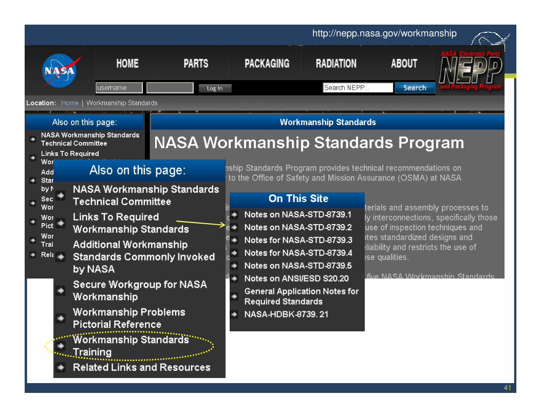
Program Public Site
http://nepp.nasa,gov/
workmanship
Links to Standards
Application Notes
Links to Training Centers
Lists of Industry Standards
Shared lessons learned
POCs for WSTC
Program CoP Site
https://secureworkgro
ups.grc.nasa.gov/wor
kmanship
Monthly telecoms
Shared documents for coordination
Shared lessons learned
Notices of ballot actions
Program Public Site
http://nepp.nasa,gov/
workmanship
Links to Standards
Application Notes
Links to Training Centers
Lists of Industry Standards
Shared lessons learned
POCs for WSTC
Mike LiuDept. QSTele: (650) [email protected]
Phil ZuluettaJet Propulsion LaboratoryTele: (818) [email protected]
Alan WallaceDryden Flight Research CenterTele: (661) 276-7531 [email protected]
Daniel HartgerinkLyndon B. Johnson Space CenterTele: (281) [email protected]
Tim WhiteStennis Space Center, MS 39529-6000(228) [email protected]
Charles GambleMarshall Space Flight CenterTele: (256) [email protected]
Kirk KettererKennedy Space CenterTele: (321) [email protected]
Art HayhurstLangley Research Center(757) [email protected]
Jeannette PlanteGoddard Space Flight CenterTele: (301) 614-5944 [email protected]
Mike CapeletyNASA Glenn Research CenterTele: (216) [email protected]
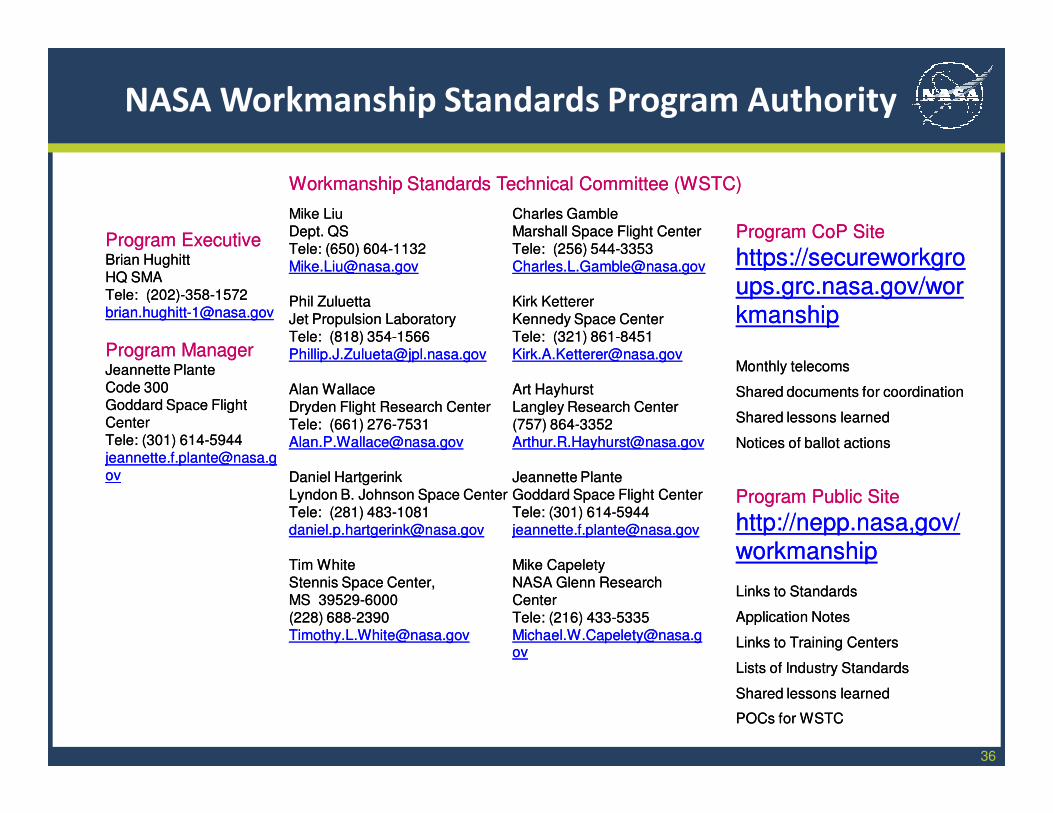
Workmanship Standards Technical Committee (WSTC)Workmanship Standards Technical Committee (WSTC)
NASA Workmanship Standards Program Authority
Program ExecutiveBrian HughittHQ SMATele: (202)[email protected]
Program ManagerJeannette PlanteCode 300Goddard Space Flight CenterTele: (301) 614-5944 [email protected]
Program ExecutiveBrian HughittHQ SMATele: (202)[email protected]
Program ManagerJeannette PlanteCode 300Goddard Space Flight CenterTele: (301) 614-5944 [email protected]
37
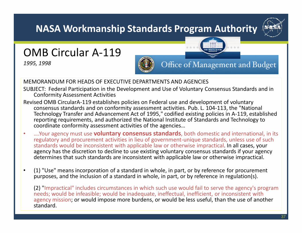
NASA Workmanship Standards Program Authority
MEMORANDUM FOR HEADS OF EXECUTIVE DEPARTMENTS AND AGENCIES
SUBJECT: Federal Participation in the Development and Use of Voluntary Consensus Standards and in Conformity Assessment Activities
Revised OMB CircularA-119 establishes policies on Federal use and development of voluntary consensus standards and on conformity assessment activities. Pub. L. 104-113, the "National Technology Transfer and Advancement Act of 1995," codified existing policies in A-119, established reporting requirements, and authorized the National Institute of Standards and Technology to coordinate conformity assessment activities of the agencies…
• ….Your agency must use voluntary consensus standards, both domestic and international, in its regulatory and procurement activities in lieu of government-unique standards, unless use of such standards would be inconsistent with applicable law or otherwise impractical. In all cases, your agency has the discretion to decline to use existing voluntary consensus standards if your agency determines that such standards are inconsistent with applicable law or otherwise impractical.
• (1) "Use" means incorporation of a standard in whole, in part, or by reference for procurement purposes, and the inclusion of a standard in whole, in part, or by reference in regulation(s).
(2) "Impractical" includes circumstances in which such use would fail to serve the agency's program needs; would be infeasible; would be inadequate, ineffectual, inefficient, or inconsistent with agency mission; or would impose more burdens, or would be less useful, than the use of another standard.
OMB Circular A-1191995, 1998
38
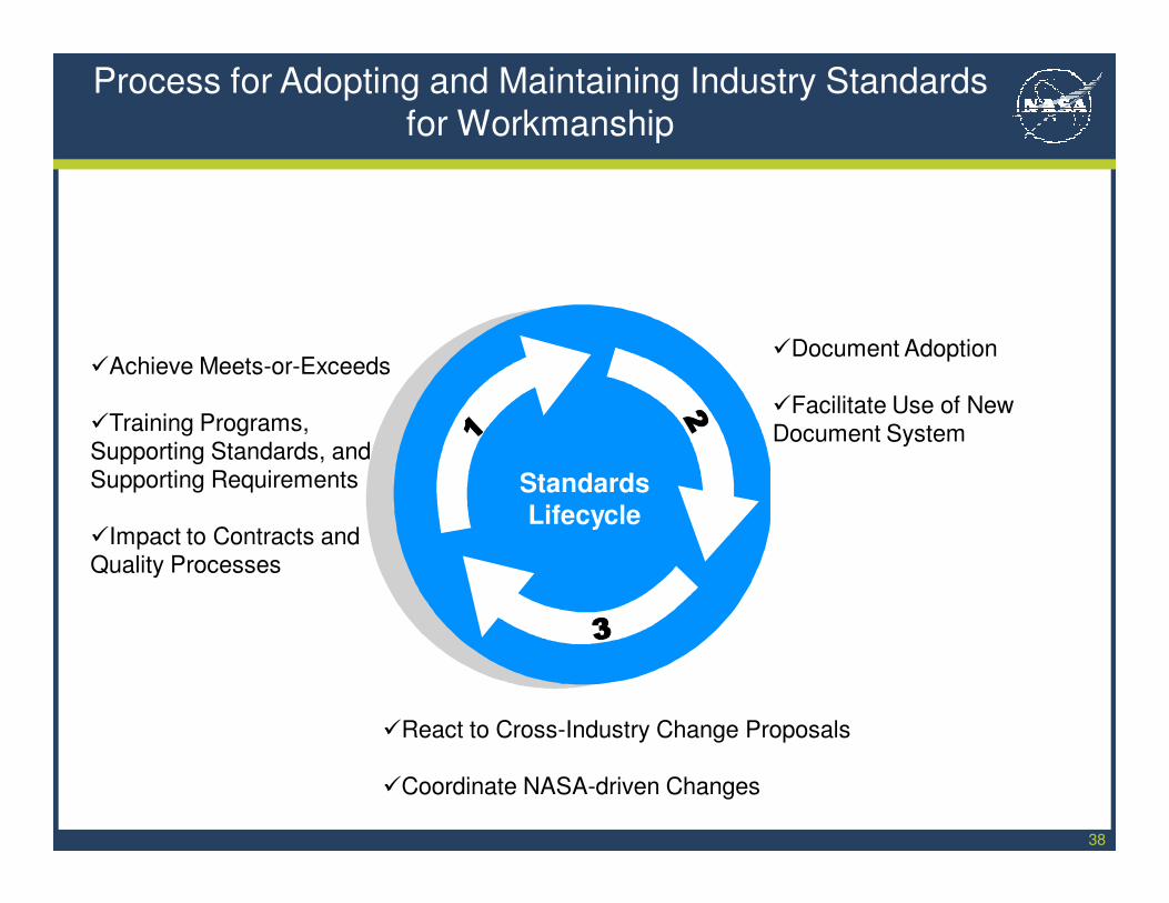
�React to Cross-Industry Change Proposals
�Coordinate NASA-driven Changes
�Document Adoption
�Facilitate Use of New Document System
Process for Adopting and Maintaining Industry Standards
for Workmanship
Standards
Lifecycle
�Achieve Meets-or-Exceeds
�Training Programs, Supporting Standards, and Supporting Requirements
�Impact to Contracts and Quality Processes
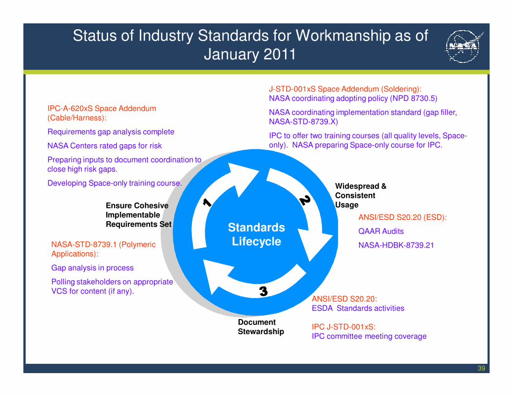
39
Document
Stewardship
Widespread & Consistent
Usage
Status of Industry Standards for Workmanship as of
January 2011
Ensure Cohesive Implementable Requirements Set Standards
Lifecycle
ANSI/ESD S20.20 (ESD):
QAAR Audits
NASA-HDBK-8739.21
J-STD-001xS Space Addendum (Soldering):
NASA coordinating adopting policy (NPD 8730.5)
NASA coordinating implementation standard (gap filler,
NASA-STD-8739.X)
IPC to offer two training courses (all quality levels, Space-
only). NASA preparing Space-only course for IPC.
IPC-A-620xS Space Addendum
(Cable/Harness):
Requirements gap analysis complete
NASA Centers rated gaps for risk
Preparing inputs to document coordination to
close high risk gaps.
Developing Space-only training course.
ANSI/ESD S20.20:
ESDA Standards activities
IPC J-STD-001xS:
IPC committee meeting coverage
NASA-STD-8739.1 (Polymeric
Applications):
Gap analysis in process
Polling stakeholders on appropriate
VCS for content (if any).
40
Technical TopicsTechnical TopicsTechnical TopicsTechnical Topics
Document Document
Repository Repository
and Archiveand Archive
Document Document
Repository Repository
and Archiveand ArchiveVCS WorkVCS WorkVCS WorkVCS Work
PolicyPolicy
DevelopmentDevelopment
PolicyPolicy
DevelopmentDevelopment
Tools for New Tools for New
TechnologiesTechnologies
Tools for New Tools for New
TechnologiesTechnologies
Telecom InfoTelecom InfoTelecom InfoTelecom InfoPBMA Community of PracticePBMA Community of PracticePBMA Community of PracticePBMA Community of Practice
41
http://nepp.nasa.gov/workmanship
42
There is no third party certification for compliance to
NASA or VCS Workmanship Standards.• NASA uses Program, Project, and contract requirements to impose the Workmanship
requirements
• NASA uses NSC audits, Project quality engineering oversight, and DCMA to verify
supplier capability and ongoing compliance
• COTS suppliers may offer compliance with VCS (e.g. IPC Standards) however the
supplier’s interpretation of the requirements may not be NASA’s (e.g. use of IPC-STD-001
Class 3, or IPC-A-610, instead of J-STD-001ES or NASA-STD-8739.2)
• DoD contracts are not required to specify Workmanship requirements. DoD do not use
supplier assessments or quality oversight that include Workmanship (except Army
AMCOM). Suppliers offer what they use to military customers using their own
interpretation of and adherence to the requirements.
NASA Workmanship Standards Program Authority
Use of military subsystems or COTS subsystems may not
meet NASA Workmanship requirements.
43
Summary of Workmanship Standards Program Authority
The Workmanship Standards Program:
Is delegated to the Program Manager from HQ OSMA (Technical
Authority)
The Program Manager advises HQ OSMA on policy and technical
issues relative to Workmanship
The Program Manager seeks inputs for establishing and maintaining
Agency Workmanship Standards from the NASA Workmanship
Standards Technical Committee
The Workmanship Program is mandated to adopt VCS’s where
practicable
Two websites are used to disseminate and collect information on
NASA Workmanship for the Program; one is secure and one is
public.
44
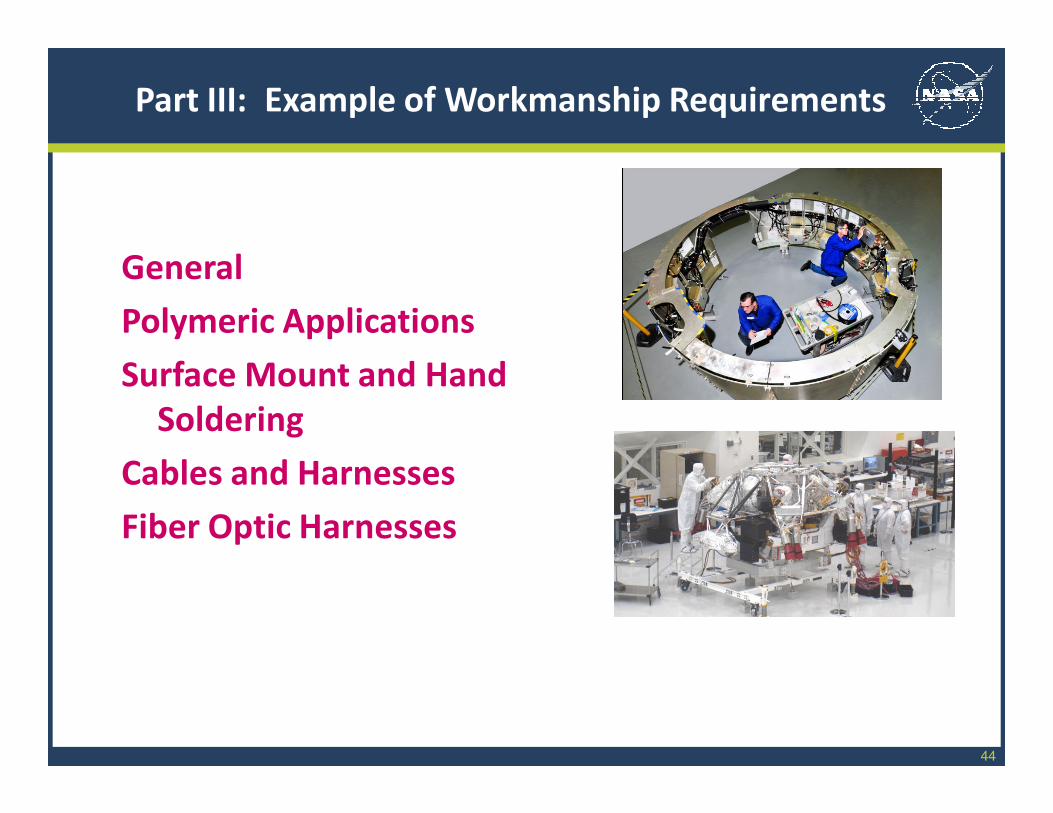
Part III: Example of Workmanship Requirements
General
Polymeric Applications
Surface Mount and Hand
Soldering
Cables and Harnesses
Fiber Optic Harnesses
12/2/2009 45
Facilities, Tools, and Equipment
Temperature: 24±3⁰C (75±5⁰F), 30% to 70% Relative
Humidity (RH)
Safety: chemical handling and storage, ESD wrist-straps are
not human protection devices
Cleanliness: use and maintenance of production area for
intended use, no food, control of foreign object debris
(FOD), proper storage of hardware in-process and after
processing.
For polymeric operations silicone operations must be
segregated
Tool Calibration: per ANSI/NCSL Z540.1
12/2/2009 46
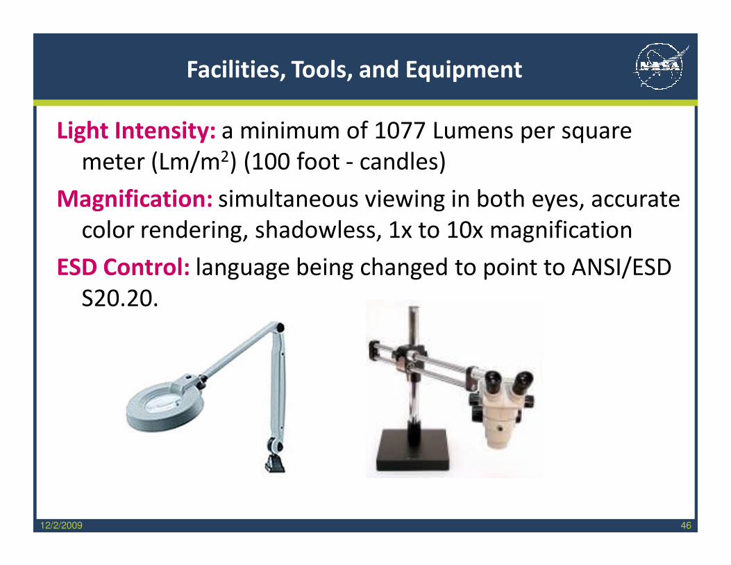
Facilities, Tools, and Equipment
Light Intensity: a minimum of 1077 Lumens per square
meter (Lm/m2) (100 foot - candles)
Magnification: simultaneous viewing in both eyes, accurate
color rendering, shadowless, 1x to 10x magnification
ESD Control: language being changed to point to ANSI/ESD
S20.20.
47
Personnel Training and Certification
Personnel: Operators, Inspectors, Level B Instructors
Certification: Guarantee employer makes that operator,
inspector, instructor meets four minimum criteria:
Training biennially, Vision biennially , Competency,
Continuous activity <6 months inactivity
Local Trainer = Level B Instructor: Local trainers may be
used but must be trained by NASA master trainer (at JPL
or GSFC school). Course materials will be provided.
Courses: Students may take classes at NASA training
centers or from a locally employed Level B instructor.
Level B courses shall be made available for review and
approval on a project-by-project basis.
48
Personnel Training and Certification
Training for adopted VCS’s
IPC J-STD-001xS: Must use IPC-certified trainer. May use one of the
two IPC courses available (modular version, or non-modular
version). May use “home grown” course. Course material shall be
made available for review and approval on a project-by-project
basis.
ANSI/ESD S20.20: Must develop a local implementation plan (local
= plant). Must train to local plan. ESDA generic courses, SATURN
generic course not sufficient for operators, program monitors,
instructors.
NASA-STD-8739.X to contain 16-page appendix to explain certification and training requirements.
49
Polymeric Applications
Polymer Material Processing: material storage, traceability
records, batch mixing, witness sample (test specimen),
hardness test
PWA preparation: cleaning, solvents, cleanliness test,
demoisturizing, priming, masking
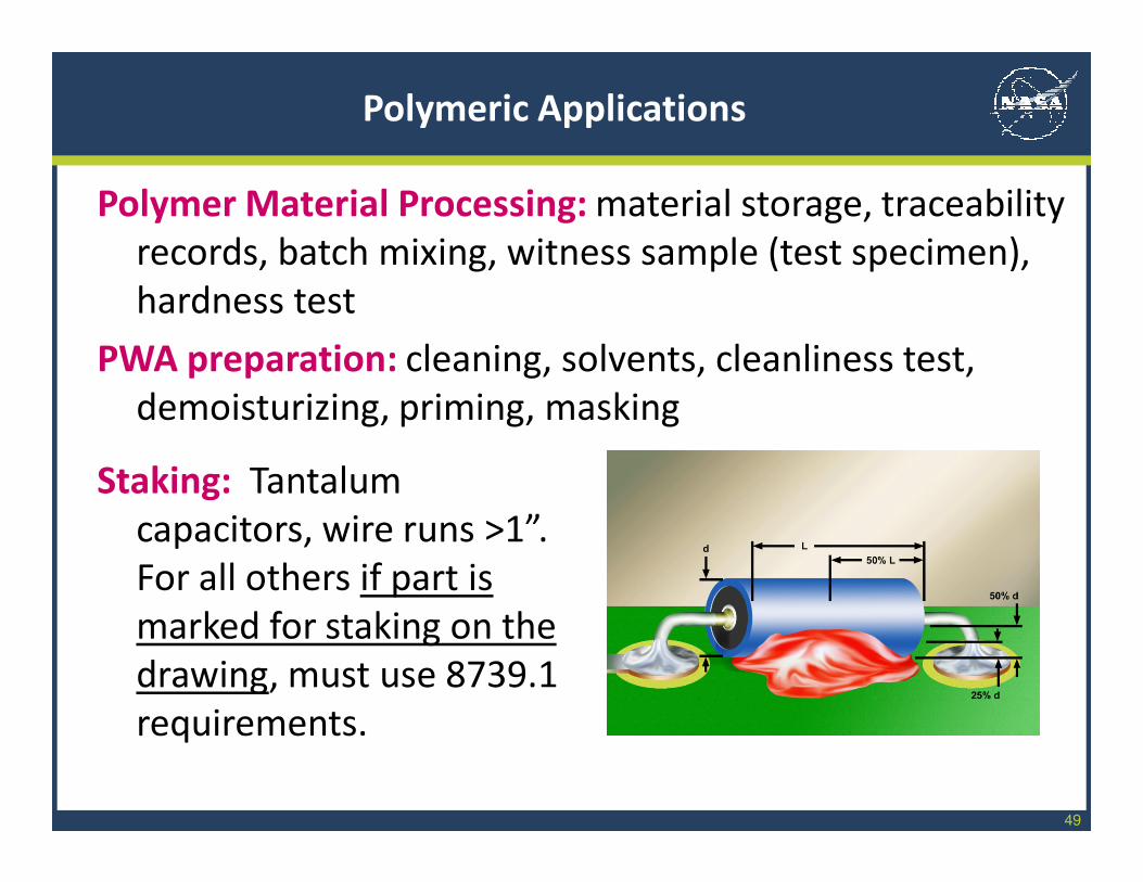
Staking: Tantalum
capacitors, wire runs >1”.
For all others if part is
marked for staking on the
drawing, must use 8739.1
requirements.

50
Polymeric Applications
Fastener Staking: applied to fastener, amount defined,
thread locking, torque striping
Conformal Coating: brushing, spraying, vacuum deposit,
dipping, pre-cure thickness measurement, bubbles,
bridging, lead interference, UV inspection, FOD
Bonding: Bondline thickness
must be defined by
engineering, squeezout
control, voiding must be
defined by engineering,
one lead free for
thermistors
51
Polymeric Applications
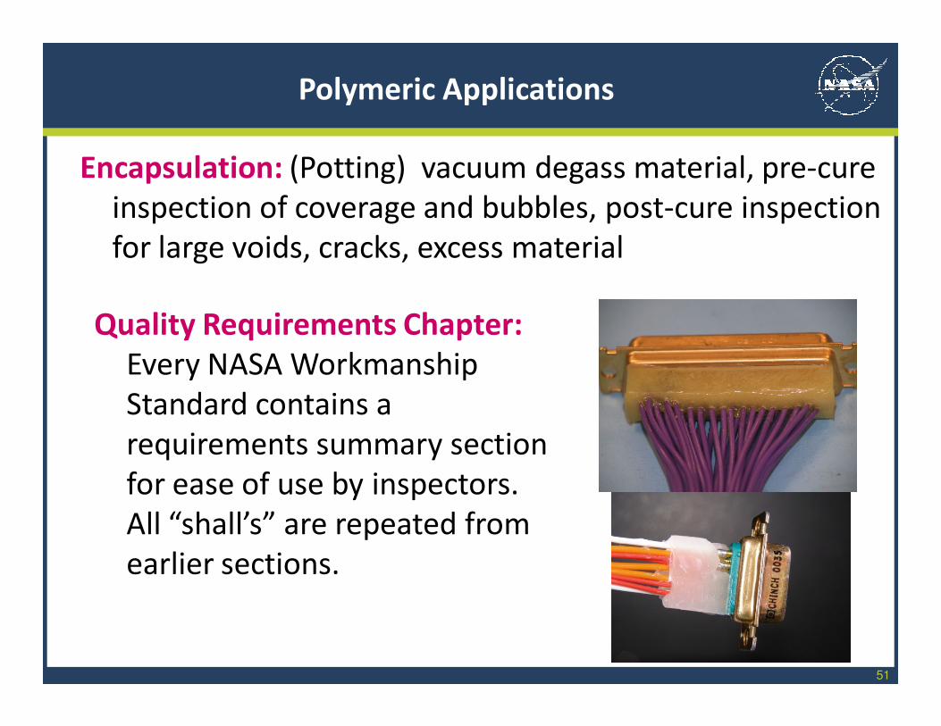
Encapsulation: (Potting) vacuum degass material, pre-cure
inspection of coverage and bubbles, post-cure inspection
for large voids, cracks, excess material
Quality Requirements Chapter:
Every NASA Workmanship
Standard contains a
requirements summary section
for ease of use by inspectors.
All “shall’s” are repeated from
earlier sections.
52
Machine and Hand Soldering
Tools: Heat source selection and control (soldering iron, hot
gas, radiant)
Materials: Eutectic solder, rosin flux, control of solder pot
alloy quality
Cleaning: Clean bare boards,
solvents, cleanliness test,
demoisturizing
Soldering Prep: Solder paste
slump and oxidation test,
deposition methods (screen,
stencil, syringe)
53
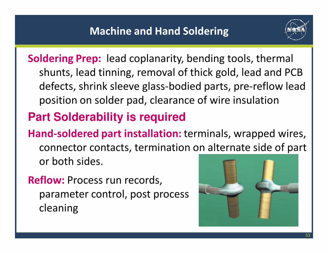
Machine and Hand Soldering
Soldering Prep: lead coplanarity, bending tools, thermal
shunts, lead tinning, removal of thick gold, lead and PCB
defects, shrink sleeve glass-bodied parts, pre-reflow lead
position on solder pad, clearance of wire insulation
Part Solderability is required
Hand-soldered part installation: terminals, wrapped wires,
connector contacts, termination on alternate side of part
or both sides.
Reflow: Process run records,
parameter control, post process
cleaning
54
Machine and Hand Soldering
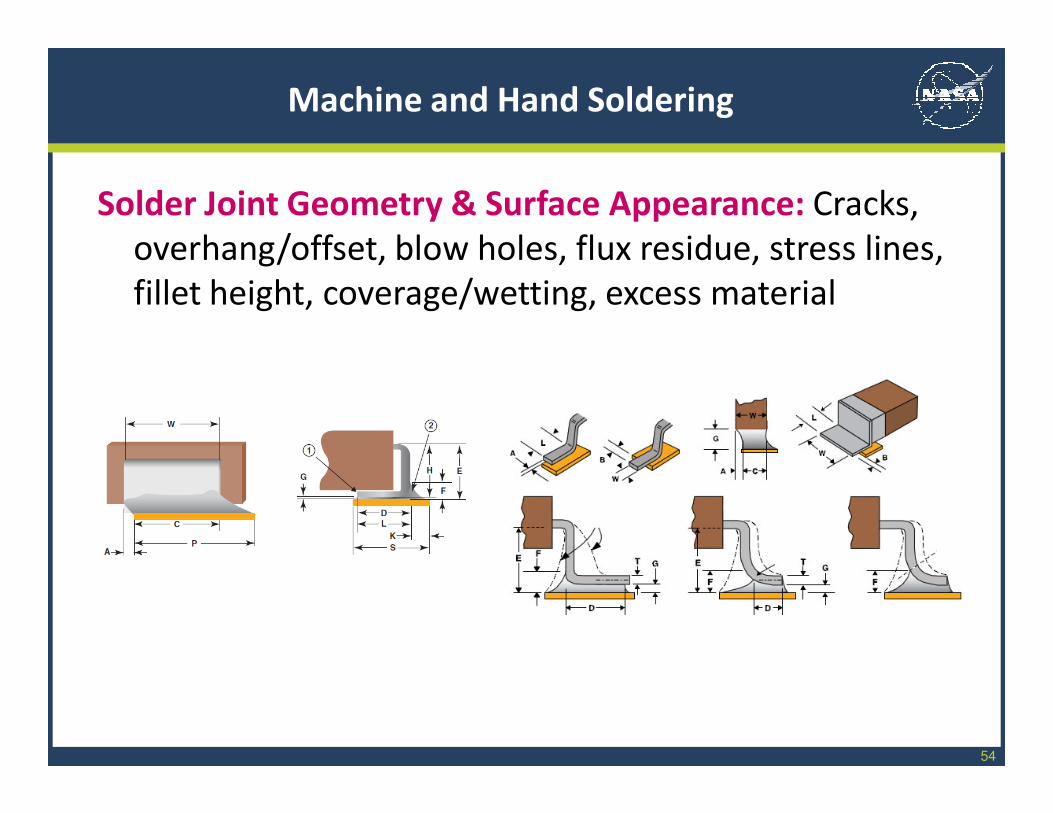
Solder Joint Geometry & Surface Appearance: Cracks,
overhang/offset, blow holes, flux residue, stress lines,
fillet height, coverage/wetting, excess material
55
Cable and Harness
Design Considerations: wire gauge selection, redundancy,
contact assignments, routing, bend radius, use of splices,
use of sealing plugs, potting connectors, signal isolation
and use of EMI shielding, use of identifier marking and
tags
Processing prep: use of full-sized mock-ups and wiring
boards, protection of harness in-process and in storage.
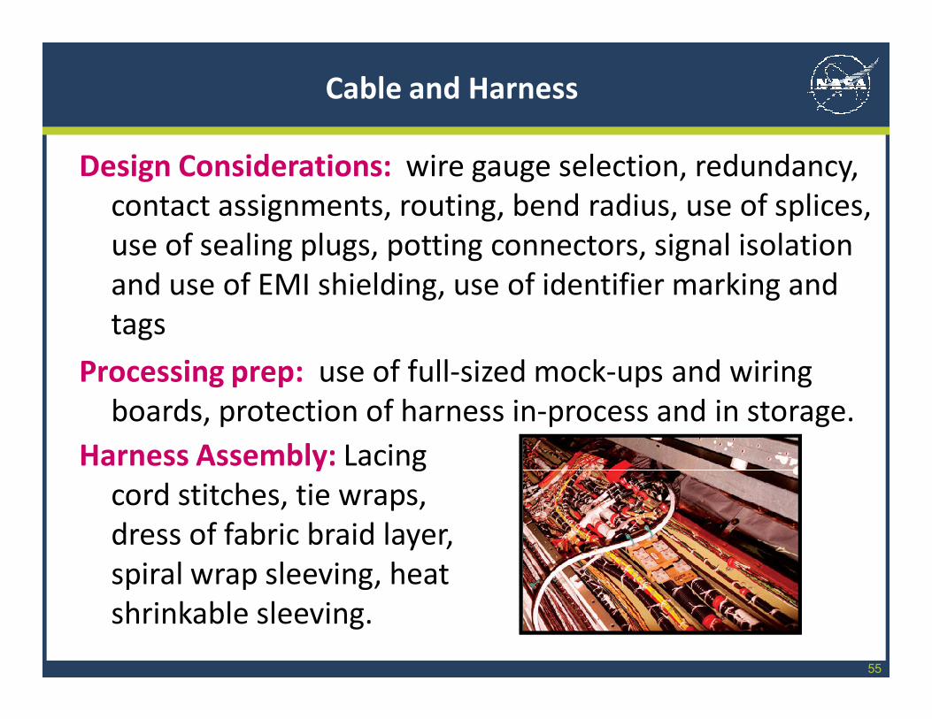
Harness Assembly: Lacing
cord stitches, tie wraps,
dress of fabric braid layer,
spiral wrap sleeving, heat
shrinkable sleeving.
56
Cable and Harness
Cable and Wire prep: wire strip, damaged conductors and
insulation, wire lay, insulation clearance, pre-tin for
solder cups, cable jacket removal
Shield prep: ground connections, dress, and crimp rings
Crimp contacts: contact quality, crimp tool type and
calibration, contact/conductor combinations, crimp
quality check using pull test
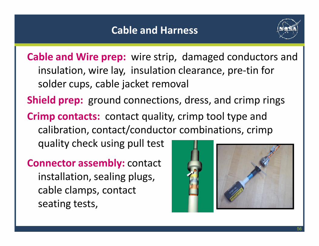
Connector assembly: contact
installation, sealing plugs,
cable clamps, contact
seating tests,

57
Cable and Harness
Splices: several types defined; solder and non-solder
Electrical acceptance testing: continuity, insulation
resistance, dielectric withstanding voltage, for coax
Voltage Standing Wave Ratio (VSWR), and time domain
reflectometry (TDR), before and after installation
58
Fiber Optic Cables
Materials: solvents, selection and use of adhesives,
traceability of materials, adhesive storage conditions,
shelf life and pot life , chemical strippers
Personal protection: from glass slivers, eye protection,
waste disposal
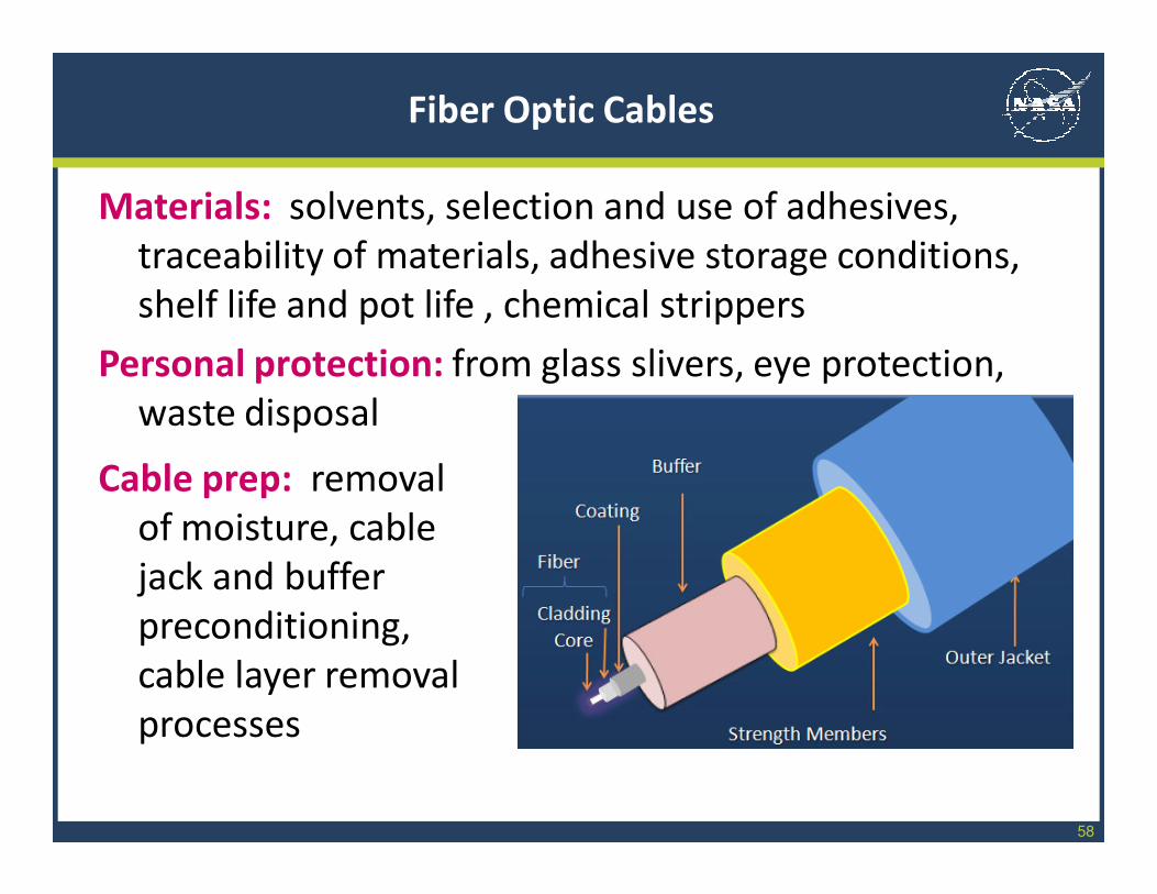
Cable prep: removal
of moisture, cable
jack and buffer
preconditioning,
cable layer removal
processes
12/2/2009 59
Fiber Optic Cables
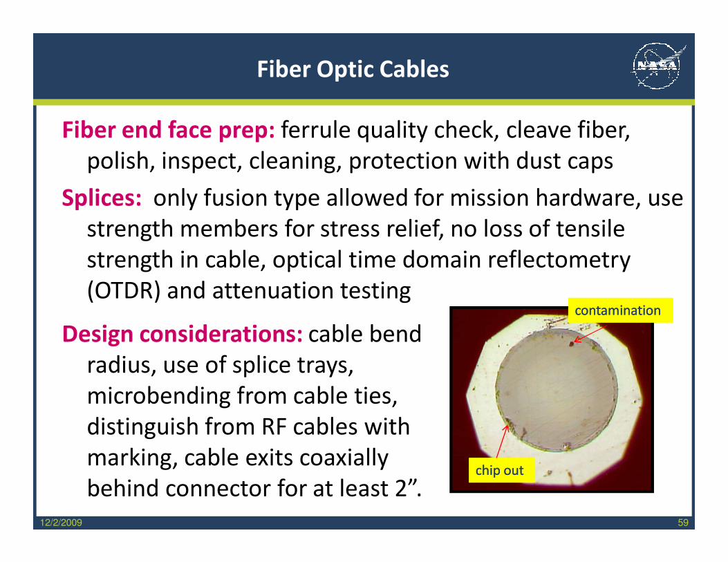
Fiber end face prep: ferrule quality check, cleave fiber,
polish, inspect, cleaning, protection with dust caps
Splices: only fusion type allowed for mission hardware, use
strength members for stress relief, no loss of tensile
strength in cable, optical time domain reflectometry
(OTDR) and attenuation testing
Design considerations: cable bend
radius, use of splice trays,
microbending from cable ties,
distinguish from RF cables with
marking, cable exits coaxially
behind connector for at least 2”.
contaminationcontaminationcontaminationcontamination
cchip outhip outcchip outhip out
12/2/2009 60
Fiber Optic Cables
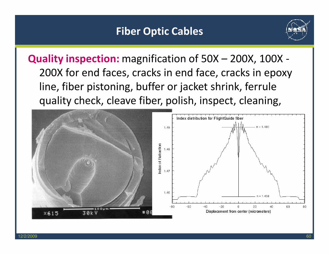
Quality inspection: magnification of 50X – 200X, 100X -
200X for end faces, cracks in end face, cracks in epoxy
line, fiber pistoning, buffer or jacket shrink, ferrule
quality check, cleave fiber, polish, inspect, cleaning,
protection
12/2/2009 61
Part IV: Electrostatic Discharge
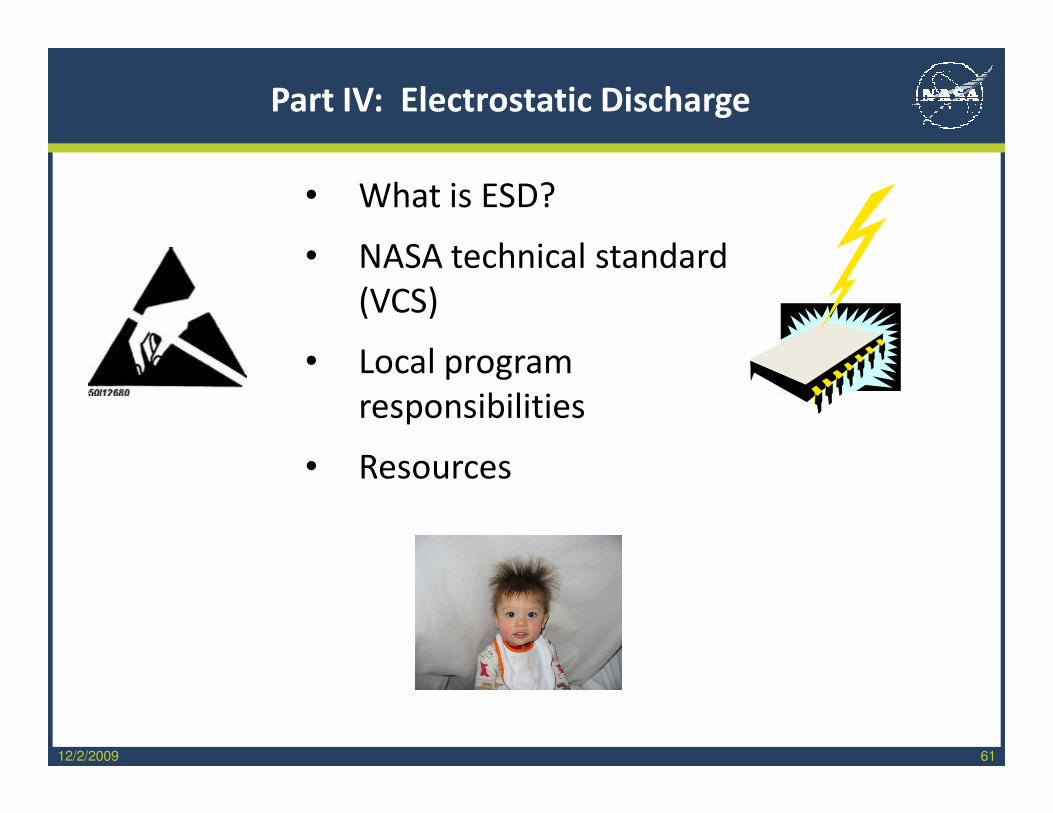
• What is ESD?
• NASA technical standard
(VCS)
• Local program
responsibilities
• Resources
12/2/2009 62
Electrostatic Discharge
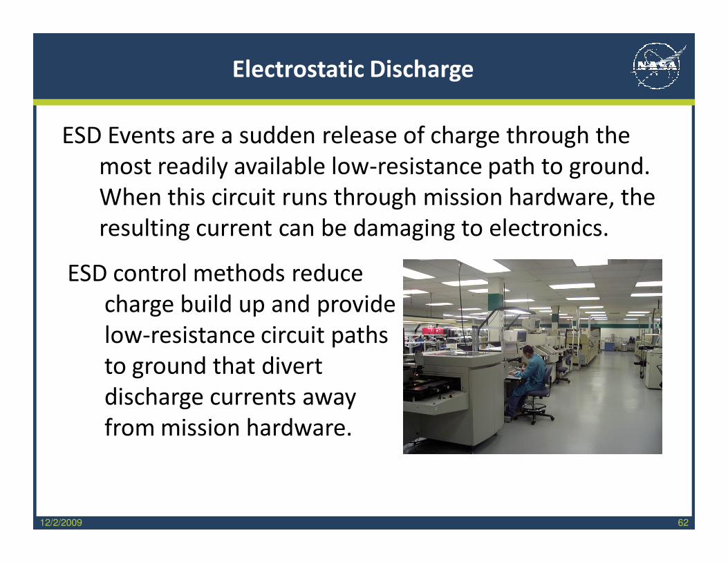
ESD Events are a sudden release of charge through the
most readily available low-resistance path to ground.
When this circuit runs through mission hardware, the
resulting current can be damaging to electronics.
ESD control methods reduce
charge build up and provide
low-resistance circuit paths
to ground that divert
discharge currents away
from mission hardware.
12/2/2009 63
Electrostatic Discharge
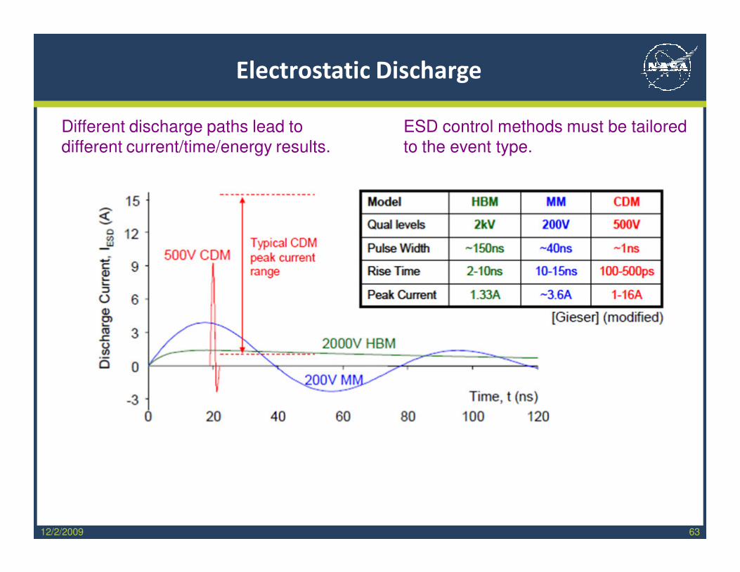
Different discharge paths lead to
different current/time/energy results.
ESD control methods must be tailored
to the event type.
12/2/2009 64
Electrostatic Discharge
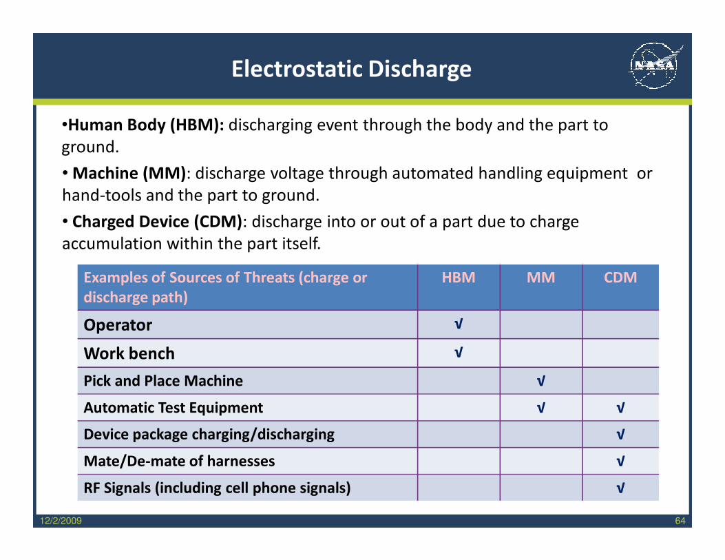
•Human Body (HBM): discharging event through the body and the part to
ground.
• Machine (MM): discharge voltage through automated handling equipment or
hand-tools and the part to ground.
• Charged Device (CDM): discharge into or out of a part due to charge
accumulation within the part itself.
Examples of Sources of Threats (charge or
discharge path)
HBM MM CDM
Operator √
Work bench √
Pick and Place Machine √
Automatic Test Equipment √ √
Device package charging/discharging √
Mate/De-mate of harnesses √
RF Signals (including cell phone signals) √
12/2/2009 65
2000X100X
4600x
8600x
66
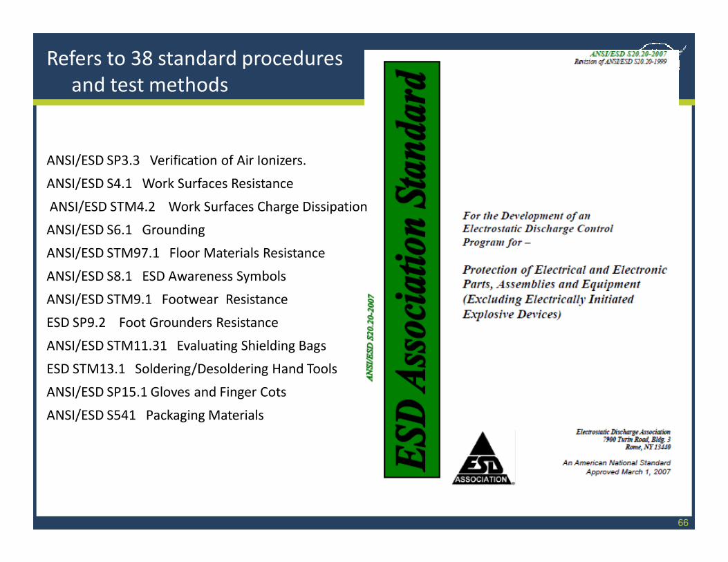
Refers to 38 standard procedures
and test methods
ANSI/ESD SP3.3 Verification of Air Ionizers.
ANSI/ESD S4.1 Work Surfaces Resistance
ANSI/ESD STM4.2 Work Surfaces Charge Dissipation
ANSI/ESD S6.1 Grounding
ANSI/ESD STM97.1 Floor Materials Resistance
ANSI/ESD S8.1 ESD Awareness Symbols
ANSI/ESD STM9.1 Footwear Resistance
ESD SP9.2 Foot Grounders Resistance
ANSI/ESD STM11.31 Evaluating Shielding Bags
ESD STM13.1 Soldering/Desoldering Hand Tools
ANSI/ESD SP15.1 Gloves and Finger Cots
ANSI/ESD S541 Packaging Materials

67
Electrostatic Discharge
7.1 ESD Control Program Plan
The Organization shall prepare an ESD Control Program
Plan that addresses each of the requirements of the
Program. Those requirements include:
• Training
• Compliance Verification
• Grounding / Equipotential Bonding Systems
• Personnel Grounding
• ESD Protected Areas Requirements
• Packaging Systems
• Marking
68
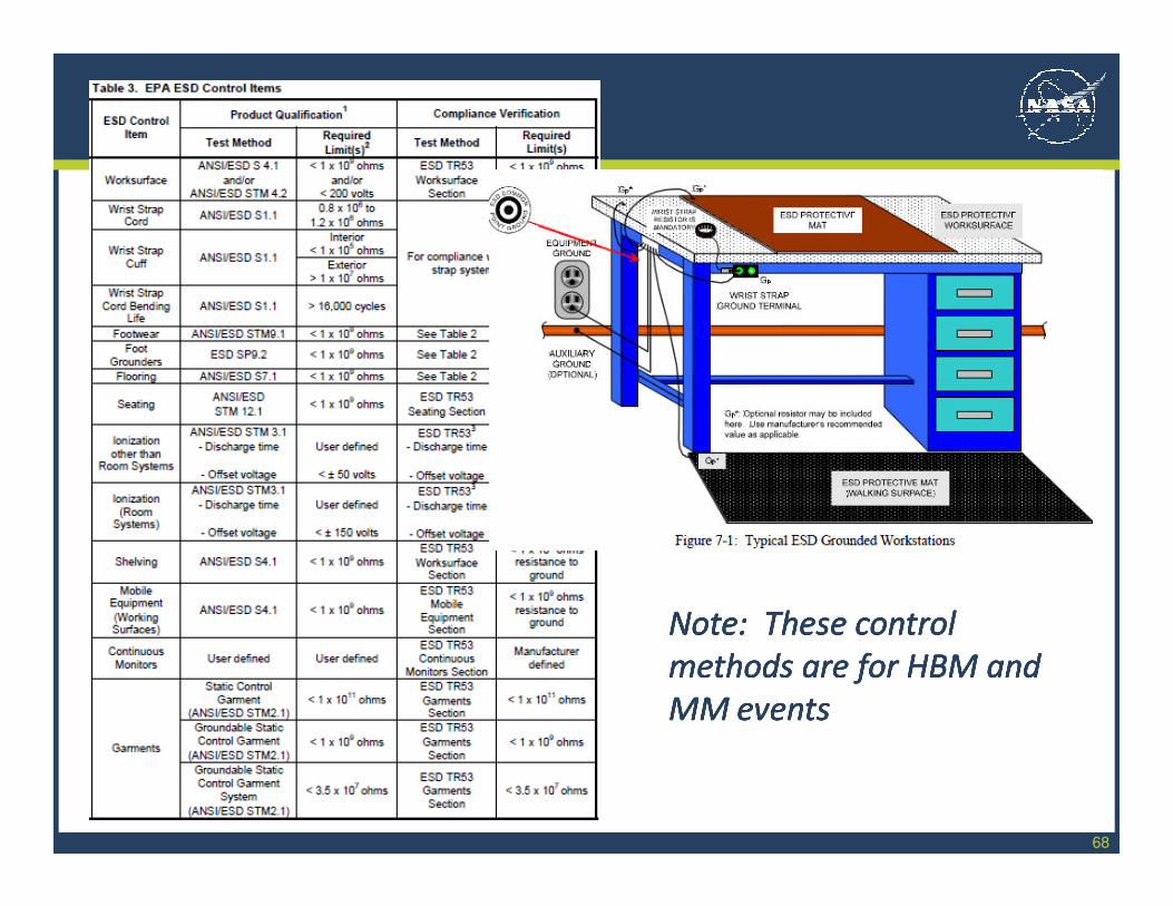
Note: These controlNote: These control
methods are for HBM and methods are for HBM and
MM eventsMM events
Note: These controlNote: These control
methods are for HBM and methods are for HBM and
MM eventsMM events
69
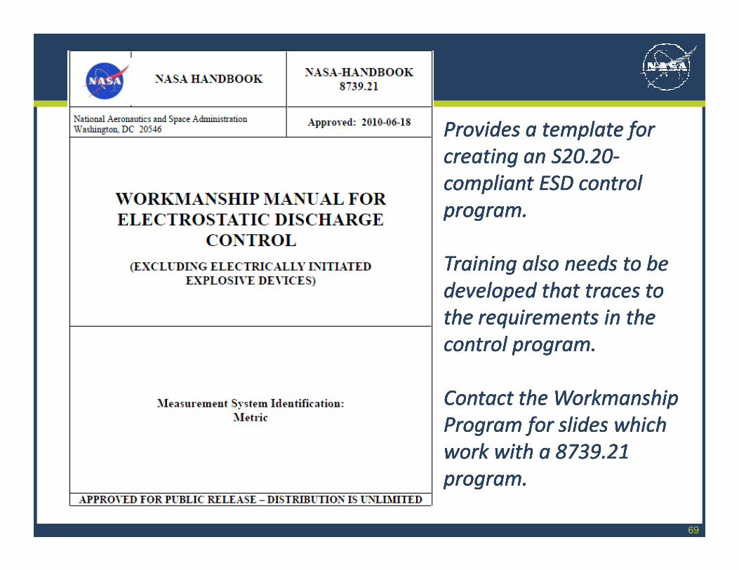
Provides a template for Provides a template for
creating an S20.20creating an S20.20--
compliant ESD control compliant ESD control
program.program.
Training also needs to be Training also needs to be
developed that traces to developed that traces to
the requirements in the the requirements in the
control program.control program.
Contact the Workmanship Contact the Workmanship
Program for slides which Program for slides which
work with a 8739.21 work with a 8739.21
program.program.
12/2/2009 70
Wrap Up
Deep BreathDeep Breath
in summary…..in summary…..
Deep BreathDeep Breath
in summary…..in summary…..
12/2/2009 71
Materials and configurations named in the Workmanship Standards are
considered technologically standard and have demonstrated high reliability
for a broad range of NASA missions and thus are mature.
The Workmanship Standards specify design, processing, and inspection
requirements, which are relevant to the materials and configurations
named, which ensure high quality hardware is supplied.
Suppliers are expected to perform manufacturing using controlled
processes, which operators implement using established procedures, and
which results in a product that is compliant with the Workmanship
requirements.
Suppliers who use configurations and materials not named in the
Workmanship Standards must establish that the resulting hardware will be
reliable for the applicable mission and must establish, declare, and use
relevant design, processing, and inspection requirements to assure that
the final items have high quality.
Seminar Summary
72
The NASA Workmanship Standards Program:
Has as its Technical Authority, NASA HQ Office of Safety and Mission
Assurance
Establishes Workmanship requirements which are applicable Agency-wide
Has a closed loop system via oversight and auditing by Project quality
assurance personnel, DCMA, and the NASA Safety Center
The NASA Workmanship Standards:
Contain requirements that enable removal and repair of defects at a relatively
low level of hardware integration when it is most affordable.
Work best as tools for Quality Assurance (rather than for reliability
assessment) and for inspecting mature technologies.
Have a technology-limited scope. Quality rules for technologies outside of
that scope must be developed, defined, and approved prior to use.
Seminar Summary
12/2/2009 73
QUESTIONS?QUESTIONS?QUESTIONS?QUESTIONS?
Top Related