


Languages
Pages
Legal


Nf2 UOSNAYROTOCNSESN SYE)ULTIPLIER(U) NAVAL POSTGRADUATE SCHOOL MONTEREY CAC L SPOI4NNOLTZ SEP 87
7UCLASSIFIlEDj F/G 17/8 U
EhEEomhEEmomiEhmhEEmhEEElhEEhhhEEEEEmhmhIEhhhEEEEEEohhEEhhEEEEEEmhmhI
IL

.5 ma
L LL
MICROCOPYf RESOLITEN TEST CHANTftAWlM SUMMJ Of $IANDS l*3 A

OMI EILECOe
* NAVAL POSTGRADUATE SCHOOLMonterey, California(0
I-
DTICS FEECTES15 WD
THESISNROSS: A Force Multiplier
by
Cheryl L. Spohnholtz
September 1987
Thesis Advisor: L. K. Crumback
Approved for public release; distribution is unlimited.
8't 9 15

REPORtT DOCUMENTATIONE PAGEis REPORT SECUITY CLASSIFICATION4 Ib 49STOICTVI MAMK*9GSUNCLASSIFIED
I* S1UO1?' CLASSICIO 71094 LU 4 I T101= IOWiAVAILAMIT W 41"T
If#01CASSOICTI~IDO~kGADIG S04EULIApproved for public release; distributioni~OCMIAfI9IOtAOPG~NO is unl imi ted.
a P146OAMt% ORGANIZATION4 REPORT NiUMHOISS) S MONITORING ORGANuZATbON REPORT NUVIIS(S)
6 6 NAME OF PERFORMING O GAMIeA~j0N 612 OFFICE SYMBOL ?a NAME OF MO NiTOSIG OAG~tdATiON
rNaval Postgraduate School Code 74 Naval Postgraduate Schoolke ADoes SS icily Pt&no lop COO) III ADDRESS (C~f. $141111. *fW lI COO)
Monterey, California 93943-5000 Monterey, California 93943-5000
so NAME 06 OuNOSNGSPO4SONING Sb 06'1C1 SYMBOL 9 PCuIEMEN? iNSAuMIN? 1O[hfiFICAION NUMBER
BeADS S0011 lCor. store. and ip CW 10 SOUSCI Of FUNDING NUMUBS
PROGNAM PROJECT ? AS,( IWORK ~j4IfELEMENT 940 1O 00 OACCESSION NO
TLE 9DR(Iaje 5eiu'etty COSAm IOtfoSAJ
NROSS: A FORCE MULTIPLIER*l'IO%.. AuTWOS(s)
Sohnholtz. Ghprvl L. _____________________,)a ~ IV *E'00of I? 'o I"ME COV111ED 14 DATE Of 4EP01?fea We AtA Day) 7 ACJf MAT.NMaster's Thesis PQOM to187Sptme 79
i6 SPOLOVINTASy %OATION
COlA?' Cols is SUMjEC? 1 14S (C@nfrweA on reveo f W AOU4 .*#W .SWIp by a AvAWRjfe'EL0 GROUP SwlIGROuP NROSS, environmental satellite, oceanographic satellite,
remote sensing,,Navy space..'
9 ,S4C? (COAve on Fewim of Rectudo *no sftwtf or book nMae'I f-
* This thesis examines the Navy Remote Ocean Siosming System (NROSS) as a forcemultiplier and shows why the Navy needs an oceanographic satellite. A history ofoceanographic remote sensors provides background and is followed by a review ofcurrent and planned environmental satellites. The capabilities of these satellitesare compared to Navy tactical requirements and deficiencies are noted. Finally,NROSS is discussed, and a look to the future shows why, more than ever, the Navyneeds NROSS. ~,. ,
;0 D S'XIU'ON'AvAaI.ASIlkTV 00 ASTRACT It ABSTRACT ICURITY CLASSIFICATION134CLS-IE0 JNL'MiT1D 0 SAME AS OP ooyc usims Unclassified 206141SIL
ija %A%41 OF RISPONS'sLI %OoVIOUAL 216 M100414P"owtooftU Are=)~ 61( YM
LTCOL Linda K. Crumback 408-646-2772 1Code 3900 FORM 147). 6. MAO 8) APO #111,00 OP& be ,wWE dA. Wite.t SICuMI? CLASS111CATION 06 POIS PAGE
All oI'"e 9111--004 a1M 00101011
Approved for public release; distribution is unlimited
NROSS: A Force Multiplier
by
Cheryl L. SpohnholtzLieutenant, United States Navy
B.S., United States Naval Academy, 1980
Submitted in partial fulfillment of the requirements for the degree of
MASTER OF SCIENCE IN SYSTEMS TECHNOLOGY(SPACE SYSTEMS OPERATIONS)
fnom the
NAVAL POSTGRADUATE SCHOOLSeptember 1987
Author. __. 0 Chery L Spohnholtfi
Approved by: k/1*6 =~tnbac, Thpais Advisor
~nd KasK. Goroch, Second Reader
Rudolf PanbpLzr, Chainnan Systems Academic Group
G6rdon E. Schacher, Dean of Science and Engineering
2

ABSTRACT
This thesis examines the Navy Remote Ocean Sensing
System (NROSS) as a force multiplier and shows why the
Navy needs an oceanographic satellite. A history of
oceanographic remote sensors provides background and Is
followed by a review of current and planned
environmental satellites. The capabilities of these
satellites are compared to Navy tactical requirements
and deficiencies are noted. Finally, NROSS Is
discussed, and a look to the future shows why, more
than ever, the Navy needs NROSS.
FAcce~ionFoNTIS CADiC TAB
j .. ..... ..
A '1
3 K
TABLE OF CONTENTS
I. INTRODUCTION . . . . . . . . . . . . . . . . 6
A. STATEMENT OF THESIS . . . . . . . . . . . 6
B. THESIS STRUCTURE . . . . . . . . . . . . 7
II. NAVY REQUIREMENTS FOR ENVIRONMENTAL DATA . . 9
A. INTRODUCTION .............. 9
B. ENVIRONMENTAL PARAMETERS AFFECTING MISSION
SUCCESS . . * .. . . . . . . . . . . . 10
C. NAVAL WARFARE REQUIREMENTS . . . . . . . 11
D. CRITICAL PARAMETERS . . . . . . . . . . . 16E. SUMMARY e. * . . . . . . . . . .e . . . . 17
III. HISTORICAL BACKGROUND . . . . . . . . . . . 18A. INTRODUCTION . . . . . . . . . . . . . . 18
B. EARLY BEGINNINGS . . . . . . . . . . . . 18
C. EARLY SENSORS IN VISIBLE/INFRARED REMOTE
SENSING . . . . . . * . . . . . . . . . 19
D. EXPERIMENTAL SENSORS IN THE MICROWAVE- REGION & * . * * * * * * . . . . . . . . 21
E. MICROWAVE REMOTE SENSING IN THE EARLY
EIGHTIES * a . .. . . . . . . . . .. . 27
F. SUMMARY . . . . . . . . . . . . . . . . . 29
IV. EXISTING/PLANNED ENVIRONMENTAL SATELLITE
SYSTEMS * . .*. . . . * . .. .. . .. . . . 31A. INTRODUCTION . . . . . . . . . . . . . . 31B. CURRENT SYSTEMS . . . . . . . . . . . . . 32
1. U.S. Programs . . . . . . . . . . . 33
2. Foreign Programs ....... . . . 38
C. FUTURE SYSTEMS . . . . . . . . . . . . . 41
1. U.S. Systems . . . . . . . . . . . . 41
2. Joint U.S. / Foreign Programs . . . . 43
4

S. Foreign Programs . . . . . . . . . . 44
D . SUMARY . . . . . . . . . . . . . . . . . 46
V. DEFICIENCIES IN SUPPORT FOR NAVY REQUIREMENTS 48A. INTRODUCTION . . . . . . . . . . . . . . 48
3 . METHODOLOGY . . . . . . . . . . . . . . . 48
C. COMPARISONS OF AVAILABLE SENSORS TO DATA
REQUIREMENTS . . . . . . . . . . . . . . 49
D . SUMEAR Y . * * * * * . . . . * * . *.* . . 55
VI. THE NAVY REMOTE OCEAN SENSING SYSTEM (NIOSS) 56
A. INTRODUCTION . . . . . . . . . . . . . . 56
B. NROSS MISSION AND PARTICIPANTS . . . . . 56
C. NROSS HISTORY . . . . . . . . . . . . . . 58
1. The Acquisition Process . . . . . . . 58
2. Reaction to NIOSS Cancellation . . . 61
3. NIOSS Revived . . . . . . . . . . . . 62
D. NROSS INSTRUMENTATION . . . . . . . . . . 63
EZ. SUYMMARY . . . . * . . . * * . * . . . . . 66
VII. SUMMARY: A LOOKXTOTHE FUTURE . . . . . . . 67
A. INTRODUCTION . . . . . . . . . . . . . . 67
B. A NEW ENVIRONMENT . . . . . . . . . . . . 67
C. COST FACTORS . . . . . . . . . . . . . . 68
D . SUMMARY . . . . . . . . . . . . . . . . . 69
LIST OF REFERENCES . . . . . . . . . . . . . . . . 70
INITIAL DISTRIBUTION LIST . . . . . . . . . . . . . 77
5

I. INTRODUCTION
A. STATEMENT OF THESIS
Why does the Navy need an oceanographic satellite?
An oceanographic satellite Is a force multiplier that
better enables the Navy to accomplish Its mission.
The Navy Remote Ocean Sensing System (NROSS) Is
currently the most viable candidate to fulfill Navy
requirements for oceanographic remote sensing from
space.
The mission of the Navy Is to ensure free and
unimpeded access to the world's oceans. This task is
accomplished through worldwide deployment of naval
forces. "Oceanographic characteristics (ocean thermal
structures, fronts and eddies, Internal waves and ice
formations) have a profound Influence on force
deployment and weapon system employment decisions In
naval operations." [Ref. 1] To support tactical naval
operations, the oceanographic data must meet the
following requirements:
1. Global coverage - The U.S. Navy operates Inevery ocean of the world and thereforerequires coverage or all ocean areas.
2. Real o near-real time recelt of data - Tomake the Information tactically relevant,It must be current.
3. All-weather day/night coverage - The U.S.Navy Is on uttwefty-our hours a day, Inall kinds or weather.
Satellite sensors can best meet these requirements.
Specifically, NROSS was designed by the Navy to provide
timely, global all-weather coverage of oceanographic
4 parameters.
Critics of a Navy-owned satellite cite several
reasons for their opposition:
1. Exlsting Department of Defense (DOD) andcivilian environmental satellites provideample oceanographic data.
6
S " ' "l P " rI'" V 1

2. The cost of the satellite is tooDrohibitive In the current era of budgetRusterity.
3. In-situ and aircraft observations aresufficient.
4. The money could be better used for moreurgent vy needs.
This thesis vill counter these arguments and prove
that the Navy has a valid requirement for its own
oceanographic satellite.
B. THESIS STRUCTURE
This thesis will have seven chapters:
Introduction, Navy Requirements for Environmental Data,
Historical Background, Existing/Planned Environmental
Satellite Systems, Deficiencies in Support for Navy
Requirements, The Navy Remote Ocean Sensing System, and
Summary: A Look to the Future.
Chapter I - This chapter provides the framework for
the thesis. It identifies the problem and sets the
stage for the following chapters.
Chapter II - For NROSS to be an effective force
multiplier, it must improve the Navy's ability to
protect the seas. Each varfare area has specific
requirements for oceanographic data. This chapter
specifies what the warfare area requirements are and
how NROSS will meet those requirements.
Chapter III - In order to understand the value of
NROSS to the Navy and how It evolved, a history of
oceanographic sensors will be presented. Satellite
design is extremely dependent on what has been done
before, and these experimental satellite sensors and
systems form the heritage for NROSS.
Chapter IV - There are many environmental
satellites In the world today, and the Navy receives
information from many of them. This chapter will
focus on existing systems and look at upcoming
7

satellites that could help to satisfy Navy
requirements for oceanographic data.
Chapter V - Even with the variety of existing
environmental satellites, Navy requirements are not
fulfilled. This chapter will identify thedeficiencies with the current satellite systems, and
examine the future system to see if they might meet
the requirements.
Chapter VI - After reviewing the history, currentsystems, and deficiencies, the Navy realized It had anoutstanding requirement for oceanographic data. The
Navy Remote Ocean Sensing System Is the proposedsolution. This chapter will look at NROSS: the
history and the satellite.
Chapter VII - Finally, a summary and outlook to thefuture will be presented. The new threat environment
will be briefly examined. The need for oceanographic
data is becoming more Important and WROSS Is the best
method to acquire that data.
Will
~8

II. NAVY REOUIREMENTS FOR ENVIRONMENTAL DATA
A. INTRODUCTION
The mission of the Navy is to maintain free and
unimpeded access to the world's oceans. This requires
global deployment of naval forces. Inadequate
environmental data can a4versely impact the tactical
employment of those forces, so specification of Navy
requirements for environmental data is necessary to
ensure adequate support. Adm. James D. Watkins,
former Chief of Naval Operations, stated "Today and in
the future certain senses are critical to our Navy's
survivability and capabilities. A Navy of 600 strong
ships would...be blind if It lacked Information about
weather." [Ref. 2]
An operational requirement is defined In JCS Pub 1as "an established need justifying the timely
allocation of resources to achieve a capability to
accomplish approved military objectives, missions, and
tasks." [Ref. 3] Navy requirements for environmental
data must be expressed In mission terms to justify the
expense of fulfilling the need. The specification of
Navy requirements for environmental data from space is
found In "Operational Requirement Satellite
Measurement of Oceanographic Parameters" (SMOP/OR
W0527-OS) which was approved 10 February 1977.
In order to provide timely, accurate environmental
data In support of naval warfare tactical
requirements, five elements are necessary:
1. Sclentifically accurate environmental*Q rorecast models.
2. Fast, large capacity computers.
3. Real time global atmospheric andoceanographic data base.
9
6' . . .! ,, . . ' . .. . . - ' , : '! . . .

4. Skilled personnel.
S. Effective communications. (Ref. 4]
Currently. the most critical element is the real
time global atmospheric and oceanographic data base.The atmospheric data base In fairly weil established.
but oceanographic data Is sorely lacking. The need to
obtain proper sampling of the data required for
analytical and numerical models is probably the mostsignificant limitation on advances In physical
oceanography. (Ref. 5] In-situ data from ships and
buoys Is limited and restricted to discrete areas (most
often located along established ocean routes).
Additionally, 90-95 % of that data comes from foreign
sources which will likely be unavailable In times of
conflict (Ref. 4]. Existing satellite sensors are
optimized for cloud observation, not ocean sensing.
These problems have hindered the ability to fulfill
Navy requirements with existing systems.
B. ENVIRONMENTAL PARAMETERS AFFECTING MISSION SUCCESS
Environmental parameters can be divided Into two
broad categories: atmospheric and oceanographic.
Atmospheric parameters affecting the ability to
perform naval varfare missions Include cloud cover.
precipitation, air temperature and humidity profiles,
vector winds, visibility, and air pressure/density.
Oceanographic parameters related to mission
* accomplishment Include sea Ice, sea surface
temperature, vertical ocean thermal structure, sea
state, marine winds, waves (period, direction, and
significant height), surface currents, bathymetry,@6 tides, and sea surface topography. These parameters
will be related to specific warfare areas.
10

C. NAVAL WARFARE REOUIREMENTS
The value of NROSS to the Navy can be measured by
its ability to assist In the accomplishment of each
warfare area mission. In the Planning and Reference
Guide for Naval Oceanography from Space, warfare areas
are defined and important environmental parameters are
identified. This section is paraphrased directly from
that source.
There are twelve warfare areas/subareas that are
affected by environmental data: Sea Based Strategic
Strike. Anti-Submarine Warfare, Anti-Air Warfare,
Anti-Surface Ship Warfare, Amphibious Warfare,
Tactical Air Strike Warfare, Special Warfare, Mine
Warfare, Ocean Surveillance, Electronic Warfare,
Command, Control and Communications, and Logistics.
Each of these areas will be defined and environmental
parameters Identified. [Ref. 6]
Sea based strategic strike is the role of the Navy
nuclear ballistic missile submarine (SSBN). Because of
Its ability to operate covertly, the SSBN Is the least
vulnerable leg of the U.S. strategic triad. Its
ability to remain an effective deterrent depends on
detection avoidance and accurate missile launch.
Environmental factors affect both areas:
1. K7?wledge of the ocean's thermal structureaffects the SSBN's ability to avoiddetection and to effectively conductsonar searches.
2. Under-ice operations require knowledge oflocation and thickness of sea ice.
3. To accurately fire submarine launchedballistic missiles (SLBM' s), data on thewinds and density of the upper atmosphereis needed.
* 4. The stability of the SSBN at launch depthcould be adversely affected by a high seastate.
5. Ambient noise caused by marine winds affectsonar utility.
6. Gravity influences the SLBM throughout itsflight.
gwii

Anti-submarine Warfare (ASW) Is the use of ships,
submarines, and aircraft to deny the enemy effective
use of his submarines. ASW is one of the warfare
areas most sensitive to oceanographic parameters,
because Its target operates In the ocean depths. Some
of these environmental parameters include:
1. Accurate understanding of the ocean thermalstructure (ducts, gradients andinhomogenetlis suc as ronts and eddies)permitf greatly Improved acoustic searchand hidlfg.
2. Tactical sonar is de raded in high seastates due to amblenf noise and domequenching.
3. Anomalies In the earth's magnetic fieldde rade per ormance of airb rne magneticangmaly detectors.
4. Sea ice greatly affects acousticpropagation and ambient noise. It
0 ~precludes use of surface ASW platforms anddegrades air ASW.
5. Weather elements (winds, clouds,precipitation) ca hamper or prevent use ofsurface and air A. w latfQorms. Employmentof acoustic sensors isd ffIcult and launchof LAMPS helicopters and or carrier basedaircraft may be prevented.
Anti-air warfare is that action required to destroy
or neutralize the enemy air and missile threat. It
includes such measures as use of interceptors,
bombers, anti-aircraft guns, surface or air-to-air
missiles and electronic countermeasures. Atmospheric
parameters are probably the most significant
information required for this warfare area.
1. Radar tqarch and electronic countermeasuresare affected by f uctuations inatmospheric temperature and humidity.
2. Carrier fli ht overations are Im aired bylow visibility knd precipitatioh.
3. Size and densit fluctuations Inatmospheric particles affect e ectro-opticsensos and weapon system per ormance.
4. Guided missile performance and chaff useare affected by winds aloft.
5. Flinht operations can be cancelled ordelayed due to high sea state.
12

6. Aircraft contrails can be detected Usingatmosphere temperature and humidity
pofles.
As the size of the U.S. Navy approaches 600 ships
and the Soviet Navy continues to expand, anti-surface
ship warfare (ASUW) increases In importance. ASUW Is
the use of aircraft, ships, and submarines to deny the
enemy use of Its ships while defending friendly
surface ships. Improved over-the-horizon weapons
systems require knowledge of the environment.
Parameters affecting ASUW include:
1. Surface search radar is affecte yatmos her1c temperature and huniditprofles whlh can create blind spots andnoma ous refraction. A high sea state candegrade radar return with c utter.
2. Electro-oMtic and infrsred weagon systemsand forward lookin In rar d vicDerformanqe Qnt arget is decrease3 bybbstructed visiblity Ismoke, clouds,precipitation).
3. High sea state and marine wind m act shiphandling and safety and the ability tolaunch fircraft. he must alsobconsidered when selecting the mode ?orcruse msl e aTtack.
4. Gynfire accuracy Is affected by windsaloft.5. The performance of acoustic homlng
torpbdyes is Influenced by the oceantherma structure.
The environment impacts heavily on the amphibious
warfare area. Amphibious warfare is the use of naval
and landing forces to attack a hostile shore and
secure a beachhead. Some of the envIromental factors
0. affecting amphibious warfare are:
1. Currents and tides, coastal btjhymetry andslog, n beach s ope fIr messfirec tly1 iluenc t e ab~,omvpersonnl and equipment ashore.
2. Landing craft (boats, air-cu hton veh1cles,and helc pters) are a fected DY localweather elemeqts (wind, sea stite,visibility and precipatation).
3. Ability to remain covert from overheadreconnaissance systema operating in thevlsiMle and Infral'ed regibns is dependenton cloud cover.
* 13

4. Mechanized heavy equipment require adequateround uoport vhch can be aeterminea by
soirtmoisture.
5. Sbre bombardment with naval gunfire isaffected by winds aloft.
Tactical Air/Strike Warfare Is the use of naval
aircraft to neutralize or destroy enemy targets on
land. One of the most recent examples of TACAIR was
the bombing of Libya on 14 April 1986. Atmospheric
parameters are extremely important In this warfare
area.
1. Cloud cover/visibilitylreclpltation arevaluable ror avoiding detection on targetapproach but hamner accurate weaponsde ivery).eepeci lly laser guided~~oronance.
2. Weather Slements (se sstate a~d marinewindas) etermine ablity to launchcarrier-based aircra ft.
3. The atmospheric temperature and humidityprofiles imDact raar pro~afat on and canaffect the abl 1tyof enemy !adar to detectincoming strikes.
4. n1luclear weapons Sre used, the radiationalout pattern and egress route are
determined by wind direction.
5. Enemy AAW forces can detect aircraftcontkails caused bi water vaporcondensation in the upper atmosphere.
6. Atmospheric denslti/oreesure influences theabi it to avoid r dar detection andconduct a low level approach.
Special warfare is the use of unconventional oftenclandestine naval forces to conduct operations
including (but not limited to) surveillance andreconnaissance In and from restricted waters. Because
of the wide variety of activities encompassed In this
warfare area, environmental requirements are tailored
for each mission. Use of cloud cover, low visibility
and precipitation for covert missions Is an Important
requirement of most missions.
Mine Warfare Is the strategic and tactical use ofmines and mine countermeasures. U.S. capabilities in
this area are currently undergoing scrutiny due to the
14
.....

mine threat In the Persian Gulf and Gulf of Oman. The
environment plays an important part In this area:
1. The ability to lay and/or sweep mines Isdependent on wind and sea state.
2. Choice of m ne, prooer setting andDositlon an deoth moor is aetermined byhydrographic effects.
3. When submarines are used to lay mines, theocean thermal structure helps o determinedetectability.
Military actions involving the use of
electromagnetic energy to detect, classify and
localize enemy forces fall In the realm of electronic
warfare. The electromagnetic spectrum is highly
susceptible to atmospheric parameters:
1. The temperature and humidity of theatmosph re determines its r fratiy ty .which affects the propagation oi electronicemissions.
2. Chaff dispersion and direction of movementdepends oh winds aloft.
Ocean Surveillance Is the use of systematic
observations of ocean areas by local or overhead
sensors to detect, locate and classify targets. It Is
the first and crucial step that must be accomplished
for any of the other warfare areas to be successful,
because destruction of a target cannot occur If target
location Is unknown. Environmental parameters have a
significant Impact on the ability to conduct ocean
surveillance:
1. Undersea surveillance arrays are affectedby the ocean thermal structure.
2. Geological structures and bathymetry affectlong range low requency sound propagation.
3. Visual and Infrared sensors on aircraft andsatellites are blinded by cloud cover anddegraded by low visibility andprecipitation.
4. Increased ambient noise caused by stormenerated wind and high seas degrades arrayperformance.
5. Acoustic argay location and orientation canbe altered y ocean currents.
15
S

6. Knowledge of sea Ice distribution Iscriticaf to developing an understanding ofunder- ce sound propa ation and amblentnoise levels.
Command, Control and Communication (C3) is the
heart of all warfare activity. C3 is the support of
decision making and resource management In the
accomplishment of a mission.
1. Veather influences most tactical decisions(as seen abQve In previous warfare areadiscusslons).
2. Worldwide electronic communications Isaffected by atmospheric temperature andhumidity profiles and solar activity.
3. Naval planning requires th use of longterm forecasts 15-10 days) to determigewhether an opera tion should be undertaken.
Providing support to the operating forces in the
-form of ordnance, provisions, equipment and spare
parts is the job of logistics. The ability to move
supplies safely and efficiently from warehouse to the
operating forces can be greatly affected by the
environment:
1. Ogtimum ship track routing uses informationo currents, wind, sea state, and stormlocations to determine the best oceanroute.
2. Ute of cloud cover can decrease probabilityor enemy detection.
3. Use of ocean temperature data can assist Inavoiding acoustib detection.
4. Sea Ice boundaries determine i e-freetransit areas and can be used foradvantageous acoustical routing.
5. Tidal storm surges affect ability to onloadsupplies In severe weather.
D. CRITICAL PARAMETERS
The environmental parameters required by naval
warfare areas as discussed above were reviewed in May
1987 by the Space Oceanography Group of the Office of
the Chief of Naval Research in coordination with the
Oceanographer of the Navy. The top ten parameters are
listed below in decreasing order of priority.
- 16

Following each parameter Is Its relative overall
military priority as identified in "Military
Requirements for Defense Environmental Satellites"
(MJCS 154-86, dated 1 August 1986).
1. Sea Surface Temperature and Ocean VerticalTemperature Prorile <37>
2. Wind (horizontal and vertical components)(4>
3. Ocean Waves (significant wave heightamplitude, wavelength, and direction) (39>
4. Sea Ice (cover thickness, type, roughnessand leads and 6ergs) <36>
5. Atmospheric Vertical Tempera ur? Profile(2>, Atmospheric Humidity Pro Ile < >,Liquid and Solid Water Cohtent <8>
6. Cloud coverafe, type, and layers/thickness 1>
7. Ocean Current Profile (spe d and direction)(44>, Near ShQre Currents (spedw and!direction <43>, and Ocean S r ace Currents?speed and direction) <44>
8. Ocean Optic l(extlnction/scatteringpro I ie) (A>
9. Visibility (aerosol concentration and size)<6>
10. Shallow Water Bathymetry <41> [Ref. 7]
It is clear that some of the most critical Navy
parameters are not a high priority In the overall
picture of military requirements. This Is one of the
reasons the Navy Is attempting to launch a Navy
specific oceanographic satellite.
E. SUMMARY
It Is evident that environmental parameters have a
great Impact on force application In all of the above
warfare areas. Although many atmospheric parameters
are available using existing satellite systems,
oceanographic parameters are less available. The next
chapter will examine early efforts in remote sensing
of the ocean to discover where the available sensor
technology came from.
17

III. HISTORICAL BACKGROUND
A. INTRODUCTION
Navy requirements in the area of remote sensing of
environmental data from space are based on a solid
background of scientific research, experimental
satellite programs, and existing environmental
systems. The technology has been proven over the past
twenty years and the concepts are valid. This chapter
will review the history of U.S. remote sensing of
oceanographic data from space.
B. EARLY BEGINNINGS
9 Since the launch of the first artificial earth
satellite SPUTNIK in October 1957, the application of
satellites to various scientific disciplines has been
explored. The concept of oceanography from space was
first investigated at a conference chaired by Dr.
Gifford C. Ewing at the Woods Hole Oceanographic
Institution In 1964. Meteorologists were already
receiving important weather data from space and
oceanographers hoped to expand upon their experiences.
Many advanced concepts of remote sensing were
discussed at the conference, including satellite
altimetry, microwave radiometry, satellite radars,
multi-spectral imagery and scatterometers. These
ideas formed the basis for application of remote
sensing from space to oceanography. For his efforts
In the field, Dr. Ewing Is sometimes called the father
p of oceanography from space. [Ref. 8, p. 14]
In 1969, NASA held two workshops on oceanography
from space to plan for future satellite sensors. The
first workshop, held at Williamstown, Massachussetts,
resulted In a document titled "The Terrestrial
18

Environment Solid Earth and Ocean Physics,
Applications of Space and Astronomic Techniques." The
techniques discussed at this conference formed the
groundwork for the development of the first
oceanographic satellite, SEASAT. From the second
workshop came a report called "The Color of the
Oceans", and this report was the basis of biological
oceanographic sensor development. These two documents
provided the framework for NASA's oceanographic
programs in the 1970's. [Ref. 8, p.15]
C. EARLY SENSORS IN VISIBLE/INFRARED REMOTE SENSING
The sixties and early seventies saw increased
interest In space-based remote sensing for
oceanographic purposes. Early remote sensors, though
primarily intended for meteorological phenomena, also
provided information on oceanographic parameters
during cloud free observations. The National
Aeronautics and Space Administration (NASA) took the
lead In environmental remote sensing research when it
launched its NIMBUS satellite series. These satellites
acted as test platforms for new meteorological sensors.
[Ref. 9] See Table 3.1.
NIMBUS 1 (1964) and NIMBUS 2 (1966) carried the
Advanced Vidicon Camera System (AVCS). AVCS was
designed to provide high resolution cloud cover
images, but In cloud free areas images of the ocean
gave Information on Icebergs and ice edge.
The High Resolution Infrared Radiometer (HRIR) on
NIMBUS2 2 identified temperature patterns of lakes and
ocean currents, and the data was read out real time to
automatic picture transmission stations. The improved
HRIR on NIMBUS 3(1969) provided the first vertical
temperature profile data on a global basis (including
19

TABLE 3.1
SUMMUARY OF EXPERIMENTS ON NIMBUS SATELLITES
N IMB9U S1 2 3 4 5 6 7
NUMBER OF EXPERIMENTS 3 4 9 9 6 9 9NUMBER OF SPECTRAL CHANNELS 3 a 28 43 34 62 79SPECTRAL REGIONS
VISIBLE X X X X X X X
INFRARED X I X X X I X
FAR INFRARED I X I X X X
ULTRAVIOLET X I I I
MICROVAVE X X X
SATELLITE EXPERIMENT MENTIONED IN TEXT
NIMBUS I AVCS
NIMBUS 2 AVCS, HRIR
NIMBUS 3 HRIR
NIMBUS 4 THIR
NIMBUS 5 ESMR. THIR
NIMBUS 6 ESME. THIR
!:!MBUS 7 CZCS. Sw.MR. THIR
[Ref. 9. p.77]
20

coverage of sea surface temperatures In cloud freeareas).
NIM4BUS 4 (1970) flew the first Temperature HumidityInfrared Radiometer (THIR), the follow-on to the ERIR.THIR provided Improved sea surface temperaturediscrimination. Under cloud free conditions, thesensor detected the division between the Gulf Streamand the colder water near the shore. Changes In theGulf Stream could be mapped on a daily basis [Ref. 10,p. 239]. Improved versions of TEIR were flown onNIMBUS 5, 6 and 7.
D. EXPERIMENTAL SENSORS IN THE MICROWAVE REGIONWhere the sixties had emphasized visible and
infrared techniques, the seventies began the use ofmicrowave sensors and their application tooceanography from space. Use of the microwave regionallows all weather, twenty-four hour coverage of theearth's surface. Because of Its ability to seethrough clouds, the microwave region is especiallyapplicable to sensing ocean parameters.
NASA continued to launch Its NIMBUS satellites andexpanded the sensor suite to microwave Instruments.The electrically scanning microwave radiometer (ESMR)on NIMBUS 5 (1972) was the first U.S. microwavesensor. It provided data on ice cover and boundariesof the polar regions. NIMBUS 6 (1975) also carriedthe ESMI. [Ref. 8, p. 399)
NIMBUS 7 (1978), the last of the series, carriedtwo new sensors with oceanographic applications. Thefirst, the scanning multi-channel microwave radiometer(SMMR), provided information on ocean and ice dynamicsand ocean surface conditions. This Instrument, whichcontinues to operate long after Its design life, hasprovided extensive data sets for algorithm testing and
21

refinement. It is the same Instrument that was
carried on SEASAT (see below). Additionally, NIMBUS 7
flew the first coastal zone color scanner (CZCS), a
sensor designed to measure chlorophyll concentration,
sediment, temperature and spectral radiances from the
oceans. [Ref. 9)
SKYLAB, the first U.S. space laboratory, was
launched 14 May 1973 and manned for three separate
time periods. Two microwave experiments, S193 and
S194, were conducted on the manned SKYLAB space
station in 1973. S193 was a combined radiometer
/scatterometer /altimeter which operated at 13.9 GHz
and used a scanning parabolic antenna. As a radiometer
it was a passive sensor, but, when operating as a
scatterometer or an altimeter, It was in the active
mode. S194 was a passive radiometer with a fixed
antenna that was designed to provide high precision
measurements of the ocean's thermal emission. [Ref.
8, p. 400] These sensors demonstrated the potential of
spaceborne microwave instruments for determination of
surface wind and atmospheric and ocean sensing.
In April 1975, information on the geoid and sea
height was detected by the first dedicated altimeter,
flown on the Geodynamics Experimental Ocean Satellite
(GEOS-3). GEOS-3 operated successfully until December
1978, providing a wealth of Information to be used as
Input for scientific models of the geold and the
ocean. [Ref. 8, p. 400]
The experience gained from these microwave
sensors, In addition to continued advances in visible
and Infrared technology, culminated In the launching
of the first oceanographic satellite, SEASAT. (See
Figure 3.1) SEASAT was launched In June 1978 and
placed In a near circular orbit at an altitude of 790
kilometers and an Inclination of 108 degrees. The
22

SOLARARRAY
TEEMTYRCKN
AND C MMUNI ATINSA'EOEE
ODLEMTTACNGli
TELEMETRY. TRACKINGA1D0 COMMUNICATION MLIHNEANTENNA No. I1IRWV RDOEE
SAR DATA ALTIMETERLINK ANTENNA
FIGURE 3.1I SEA SATELLITE (SEASAT)[Ref. 6, p. 4-21]
23

requirements for SEASAT were first Identified by a
users group consisting of Air Force, Navy, National
Aeronautics and Space Administration (NASA), and
National Oceanic and Atmospheric Administration (NOAA)
representatives. The satellite was established as a
"new start" in 1975. [Ref. 11, p. 276] From the
Initial conception to the actual launch, SEASAT was
designed for the user by the user.
SEASAT carried a five instrument sensor package
including three active sensors and two passive sensors.
The observed wavelengths were visible, infrared and
microwave, thus providing concurrent coverage over a
wide wavelength spectrum. Active sensors included a
radar altimeter (ALT), a microwave scatterometer
(SEASAT-A Scatterometer System, SASS) and a synthetic
aperture radar (SAR). The passive sensors were a
visible and infrared scanning radiometer (VIRR) and a
scanning multi-channel microwave radiometer (SMM).
(See Table 3.2)
The sensors flown on SEASAT all had a direct
heritage from previously orbited Instruments with one
exception: the synthetic aperture radar. Fundamentally
a radar, the SAR used synthetic aperture techniques to
make a 10 x 2 meter size antenna operate as a 3 km
diameter antenna thus providing higher resolution
Images. The SAR was designed to obtain radar Images
of the sea surface revealing ocean wave patterns,
information on water/land Interaction, and data on ice
and snow cover. Because of the high data rate (227
megabits/sec) required to achieve the desired
*resolution, no SAR data was recorded on board.
Instead, the satellite observations were relayed in
real time to ground stations when the SAR was In line
of sight. The five ground sites were located in
24
I

TABLE 3.2
SUMMARY OF SEASAT INSTRUMENTS
NAME SWATH WIDTH FREQUENCY MEASURED PARAMETER
ALTIMETER 2.4 TO 12 KM 13.5 GHZ DYNAMIC HEIGHTS TO +10(ALT) CM AND SIGNIFICANT
WAVE HEIGHT TO SAMEACCURACY FOR WAVESLESS THAN 20M.
SCATTEROMETER 200-700 KM 14.6 GHZ INFERRENCE OF SURFACE(SASS) ON EITHER WINDS FROM DOPPLER
SIDE OF NADIR RETURN TO +2M/SEC ANDTRACK +20 DEGREES DIRECTION
OVER RANGE OF 4 TO 26M/SEC.
SYNTHETIC 106 KM TO 1.275 GHZ WAVES AND WAVE SPECTRAAPERTURE STARBOARD ICE BOUNDARIES, SEARADAR CENTERED 20 STATE IN ALL WEATHER.(SAR) DEGREES OFF
NADIR
SCANNING 60 KM TO 6.6. 10.7. ALL WEATHER MEASURE OFMULTICHANNEL STARBOARD 18, 21, AND SEA SURFACE
MICROWAVE 37 GHZ TEMPERATURE TO +2 K,RADIOMETER SURFACE WIND SPEED TO(SMMR) +2 M/SEC.
VISIBLE/ 2266 KM .5-.9 um., FEATURE IDENTIFICATIONINFRARED CENTERED 16.5-12.5 CLOUD AND SURFACERADIOMETER ON NADIR um TEMPERATURES.(VIRR)
[Ref 8, p. 47]
25
Alaska, California, Florida, Newfoundland, Canada and
Oak Hanger, England. Since no stations were located
In the southern hemisphere, no SAR imagery of that
area was received. [Ref. 12)
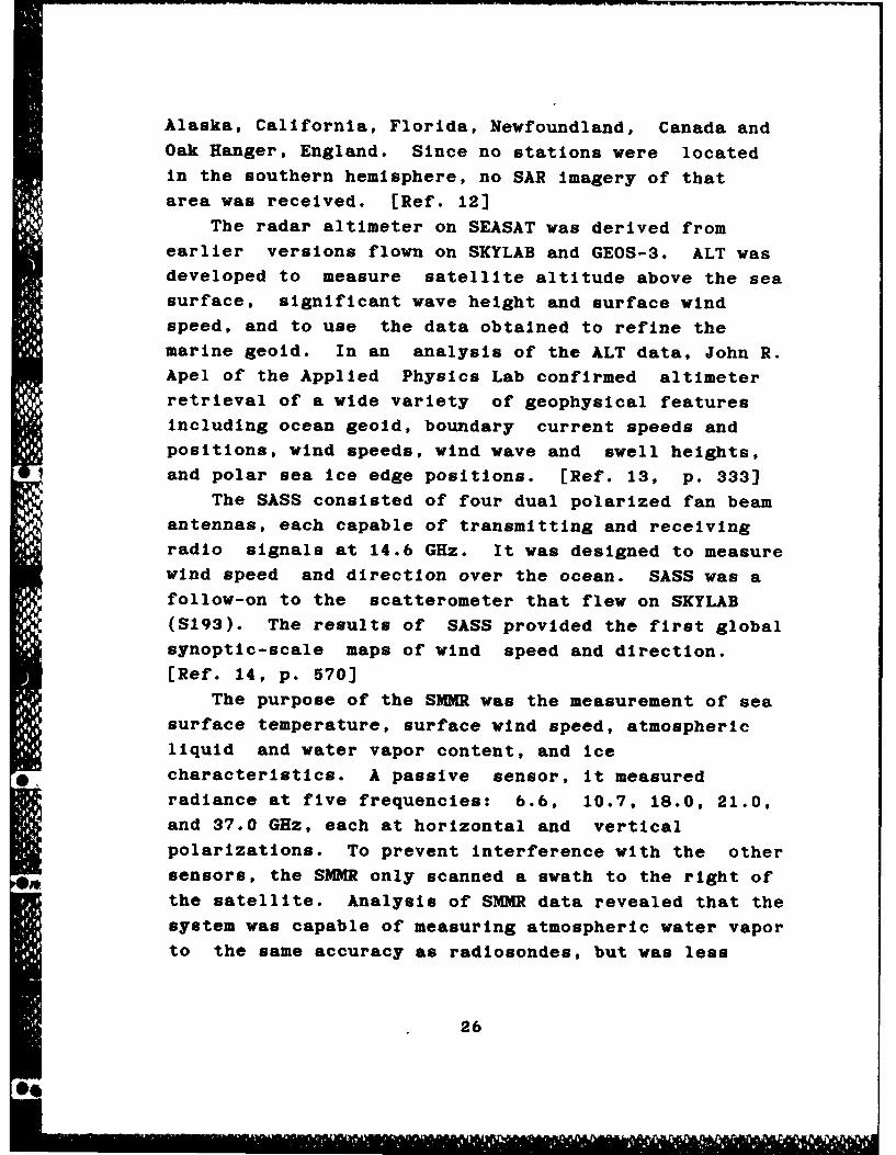
The radar altimeter on SEASAT was derived from
earlier versions flown on SKYLAB and GEOS-3. ALT was
developed to measure satellite altitude above the sea
surface, significant wave height and surface wind
speed, and to use the data obtained to refine the
marine geoid. In an analysis of the ALT data, John R.Apel of the Applied Physics Lab confirmed altimeter
retrieval of a wide variety of geophysical features
including ocean geold, boundary current speeds and
positions, wind speeds, wind wave and swell heights,
and polar sea ice edge positions. [Ref. 13, p. 333)
The SASS consisted of four dual polarized fan beam
antennas, each capable of transmitting and receiving
radio signals at 14.6 GHz. It was designed to measure
wind speed and direction over the ocean. SASS was a
follow-on to the scatterometer that flew on SKYLAB
(S193). The results of SASS provided the first globalsynoptic-scale maps of wind speed and direction.
[Ref. 14, p. 570]
The purpose of the SIMMR was the measurement of sea
surface temperature, surface wind speed, atmospheric
liquid and water vapor content, and ice
*. characteristics. A passive sensor, it measured
radiance at five frequencies: 6.6, 10.7, 18.0, 21.0,
and 37.0 GHz, each at horizontal and vertical
polarizations. To prevent interference with the other
sensors, the SlMR only scanned a swath to the right of
the satellite. Analysis of SMMR data revealed that the
system was capable of measuring atmospheric water vapor
to the same accuracy as radiosondes, but was less
26

precise In measurements of sea surface temperature and
surface winds. [Ref. 15, pp. 463-476]
Another passive sensor and the only SEASAT
instrument not to operate In the microwave region was
the visible and infrared scanning radiometer. The
VIRR provided image feature Identification In support
of the other four sensors and obtained thermal images
of the ocean. [Ref. 16, p. 17]
Although SEASAT had a planned three year lifetime,
It suffered an electrical failure on 10 October 1978
after just over 100 days in orbit. The shortened
lifespan did not detract from the encouraging results
obtained by the SEASAT sensor suite:
After 1-1/2 years o~ Intensive anal pie ... a mu ti-disciplinary team o sclentists enyneers, nt -analysts has concuded tat tf enlleorito thenals or me asuring ueop yical Dae etrs haveOen met. Consequenty, the overall groje tobjective of demonstratng the concept 0 oal,nearly all weatner, micowave ocean gurvei11ancecapability has been accomplished. lel. 17, p. 3J
Although SEASAT has been dead for nine years. analysisof the data continues to this day. SEASAT was the
significant breakthrough oceanographers had dreamed ofback In 1964. The challenge for the next decade wouldbe to take the proof of concept satellite andtransform it Into a fully operational oceanographicsystem.
E. MICROWAVE REMOTE SENSING IN THE EARLY EIGHTIESSeveral proposals were raised concerning the next
oceanographic system. NASA had originally planned afollow-on satellite called SEASAT-B, while theDepartment of Defense (DOD) suggested deployment ofthe Remote Ocean Measuring System (ROMS). Realizing
that budget constraints would not support the launchof more than one satellite, a joint proposal was made.The National Oceanic Satellite System (NOSS) would bean operational ocean monitoring system for military
27
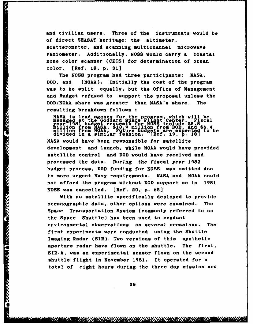
and civilian users. Three of the Instruments would be
of direct SEASAT heritage: the altimeter,
scatterometer, and scanning multichannel microwave
radiometer. Additionally, NOSS would carry a coastal
zone color scanner (CZCS) for determination of ocean
color. [Ref. 18, p. 31]
The NOSS program had three participants: NASA,
DOD, and (NOAA). Initially the cost of the program
was to be split equally, but the Office of Management
and Budget refused to support the proposal unless the
DOD/NOA share was greater than NASA's share. The
resulting breakdown follows :
NASA is lead agency for the program, which will bemanaged at the Godard Spaqe Flight Center. Fiscalyear 198 budlt reguesto rot NO 1 Include $5.8billion from NASA, 513.9 million from DOD, and $6.4mil lion from NORA * Future budgets are expected to bedivided In a similar fashion. tRef. 19, . 18J
NASA would have been responsible for satellite
development and launch, while NOAA would have provided
satellite control and DOD would have received and
processed the data. During the fiscal year 1982
budget process, DOD funding for NOSS was omitted due
to more urgent Navy requirements. NASA and NOAA could
not afford the program without DOD support so In 1981
NOSS was cancelled. [Ref. 20, p. 65)
With no satellite specifically deployed to provide
oceanographic data, other options were examined. The
Space Transportation System (commonly referred to as
the Space Shuttle) has been used to conduct
environmental observations on several occasions. The
first experiments were conducted using the Shuttle
Imaging Radar (SIR). Two versions of this synthetic
* aperture radar have flown on the shuttle. The first,
SIR-A, was an experimental sensor flown on the second
shuttle flight In November 1981. It operated for a
total of eight hours during the three day mission and
28

provided limited coverage of the world's oceans.
[Ref. 12, p. 671]
SIR-B, an upgraded version of SIR-A, deployed inOctober 1984 Into a 57 degree inclination orbit. The
improvements in the system included:
a. Adding a mechanical tilt mechanism to allowthe antenna variable incidence anglesbetween 15-60 degrees.
b. Increased bandwidth.
c. The addition of an antenna panel toincrease antenna size.
d. Use of a digital data processor instead ofthe data recorder on o SIR-A.
This mission provided increased coverage of the oceansand northern fringes of the winter Antarctic ice pack.
[Ref. 12, p. 674]
In addition to observations by shuttle crews, InOctober 1984, Dr. Paul Scully-Power, a civilian
oceanographer from the Naval Underwater Systems Center,
initiated the Navy-sponsored oceanographer in spaceprogram. The success of that flight led the Navy torequest future flights for Naval Oceanographic
Observations on Shuttle (NOOS). The program wasdesigned to be a continuing, at least once a yearoccurrence. [Ref. 6, p. C-6] The aftermath of theChallenger accident and resulting negative publicity
concerning civilians in space will probably preclude
any NOOS flights In the near future.
F. SUMMARY
Oceanographers were confident that SEASAT wouldusher in a new era of oceanographic remote sensing:
Undoubtedly oceano ra h will benefit reatly fromfuture satellite ald Ynitrument packa to modelledon SEASAT and Itspayload. Indebd, if is not toomuch to expect that oceanograpny ...willundergorevolutionary growth In scale and practicalslanificance as ocean-monltoring satellitesTnUrease our knowlqd e of maritime condlilons by averitable quantum leap. [Ref 21, p.216 i
29
6C

Did this revolutionary growth occur? The next chapterwill look at current and planned environmental
satellites with possible oceanographic applications.
3
_ 30
4e

IV. EXISTING/PLANNED ENVIRONMENTAL SATELLITE SYSTEMS
A. INTRODUCTION
Navy requirements for environmental data are
currently being supported by existing DOD and civilian
environmental satellites. The only Navy satellite
providing oceanographic data is GEOSAT (Geodetic
Satellite). The ability of these satellites to
fulfill Navy requirements will be examined. If
current systems can provide sufficient information to
the Navy, the need for NROSS would diminish.
In DOD, the Air Force is the executive agent for
the Defense Meteorlogical Satellite Program (DMSP).
The National Oceanic and Atmospheric Administration
(NOAA) Is the lead agency for the two civilian
environmental programs: Geostationary Operational
Environmental Satellite (GOES) and NOAA Advanced
TIROS-N (Television and Infrared Observation
Satellite). A third program, LANDSAT, is now operated
by a commercial organization, Earth Observation
Satellite Company (EOSAT). These four satellite
systems make up the U.S. operational space program for
earth observation.
Remote sensing is an international cooperative
effort, with some successful instances of exchange of
environmental data. Because of this, existing foreign
environmental satellites will also be Included In the
group of satellites that could help fulfill Navy
requirements for environmental data. Currently
400 deployed are the European Space Agency's METEOSAT;
France's SPOT; India's INSAT; and Japan's GMS and
MOS-1. These satellites will be examined later in
this chapter.
31
e7~

The year 1986 yas catastrophic for the U.S. apaceprogram. With the tragic lose of the space shuttleChallenger on 28 January, the Space Transportation
System was grounded. Latest estimates put the firstlaunch of the revised shuttle in summer 1988. Otherlaunch vehicle failures Included the 18 April loss ofa Titan 34D expendable launch vehicle (ELY) carrying amilitary satellite and the failure of a Delta ELYcarrying GOES-G on 3 May. These accidents virtually
halted U.S. space launches In 1986. The European
Space Agency lost the use of Its primary launchvehicle, the French Ariane rocket, when It wasgrounded following a launch failure In May 1986. The
Ariane Is scheduled to resume launches In the fall of
1987.
These events have negatively affected futureenvironmental satellites. First, a delay In launch
timetables has occurred. Second, many countries arere-evaluating their budget allocation for space
systems. Finally, there is a new-found reluctance tobuild satellites which can only be shuttle-launchedbecause the availability of the shuttle as a
commercial launch system Is questionable.With that background In mind, environmental
satellites planned for launch In the near future(1987-1995) will also be examined for their ability tomeet Navy requirements. U.S., joint, and foreignprograms will be reviewed.
B. CURRENT SYSTEMSThis section will describe the existing worldwide
network of environmental satellites. U.S. systems willbe presented first, followed by foreign programs.
32

1. U.S. Promrams
a. Geodetic Satellite (GEOSAT)
On 12 March 1985, the Navy's Geodetic
Satellite (GEOSAT) was launched from Vandenberg Air
Force Base Into a near-polar 800 kilometer orbit.
GEOSAT carries just one sensor, a SEASAT type
altimeter. It i the first altimeter to be launched
since SEASAT, and the only one of its kind to fly
during this decade. GEOSAT Is designed for a dual
mission during its three year expected life: first, to
accurately determine the marine geold and second, to
provide data on wind speed and significant wave
height. When the geold measurements were completed in
1986, the satellite was "repositioned Into a repeat
orbit to optimize oceanographic measurements of wave
height and surface wind speed and to locate ocean
fronts and eddies." [Ref. 22, p. 69]
b. Noe Meteorological Satellite Program
The mission of DMSP Is "to provide high
quality weather and other environmental data In a
timely fashion to the Armed Forces of the United
States for tactical and strategic missions." [Ref.
23, p. 96] As such, It is the primary contender to
satisfy Navy needs for environmental data. Security
of DMSP data is achieved through the capability to
encrypt the downlink transmission and protect the
uplink transmission by a command receiver lockout
system which only accepts commands from the three
direct readout stations.
In 1969, the Navy joined DMSP and It became
a tri-service program. The Navy Fleet Numerical
Oceanographic Center began receiving DMSP data in the
early seventies, and In 1971 the USS Constellation
(CV-64) Installed the first shipboard direct readout
terminal, an AN/SMQ-6. [Ref. 24, p. 132] Subsequent
33

carriers received the AN/SM0-10 Production Shipboard
Receiving Terminal on a one-per-year basis until a
total of eight terminals were installed.
Procurement ended at that time to prepare
for Introduction of the AN/SMQ-11 meteorological data
receiver / recorder set. The Tactical Environmental
Support System (TESS 3) will operate in conjunction
with the AN/SMO-11 and will be capable of receiving
DMSP, NOAA, GOES WEFAX data (defined below) and NROSS
data (when available).
The first TESS (3) systems are scheduled
for Installation In 1991. A total of 71 units are
planned, Including 44 shipboard and 27 shore-based
units. 18 aircraft carriers, 4 battleships, 2 command
0' and control ships, 5 LHA's, 7 LPH's, 6 LHD's and 2
AGF's will receive the terminals. [Ref. 25]
The DMSP has a history of innovation. In
1970, the Block 5A satellite series Included the first
3-axis stabilized meteorological satellite. The first
satellite of the Block 5D series, Block 5D-1 In 1976,
was the first operational satellite to use on-board
computers for command and control, attitude
determination and control, ascent guidance and
control, and redundancy/power management. [Ref. 24]
The first satellite of the current Block
5D-2 series of DMSP satellites, F6, was launched In
1982. Two satellites form the constellation and are
phased so one crosses the equator at 0600 and the other
at 2200. An Atlas E launch vehicle from Vandenberg Air
Force Base sends the spacecraft into a 833 kilometer,
98.7 degree inclination orbit. The Block 5D-2 series
has greater power available than earlier Block 5
satellites to support additional sensors. [Ref. 23]
Deployed sensors include:
1. 0perationa Lnescan Sstem_(0L ) -owcnannez oscillating ra iome er ?or gzooa?
34
-. e

day/niaht observation of cloud cover andtemperiture. In 1979 the infrared bandwas narrowed from 8-1 microns toj0.5-12.6 microns in response to Navy needsr mproved sea surrace temperature
sensitivity [Ref. 24J
2. SfecIa Sensor MicrowavelTemperature/SMT - a seven channel microwave
temperature sounder operating at 50-60 GHzis Used to retrieve the verticalatmospheric temperature profile.
3. Space Environment Sensor Suite (SESS) - avariety of sensors used to monitor thespace environment Including the i nls nericplasma and scintillation monitqr (SSIE/S)and the preci ittilg electron protonspectrometer SSJ 4).
4. Special Sensor Mlcrowave/Ima er (SSM/I) - Anew sensor was added to the flock 5D-2series with the launch of F8 on 6 July1987. Built by Hughes Aircraft Company,this sensor prbvI des data on ocean surfacewind speed, cloud water content areas andintensity of precipitation, soli moisture,and Ice age ahd coverafge. It is a 7channel rour frequency microwaveradiometer that uses a conical scanpattern. It is the first jointly developedAir Force/Navy sensor and will also fly onNROSS.
c. Geostationar OperationalEnvironmental Satellite (GOES)
GOES Is the backbone of the U.S.
geostationary environmental system. The GOES
constellation consists of two satellites, GOES-East at
75 west longitude and GOES-West at 135 west longitude.
These two spacecraft provide near-continuous storm
tracking, cloud analysis data, surface temperature
data, space environment monitoring and remote sensor
data relay.
The current series of satellites was firstlaunched in 1975. GOES 1-3, built by Ford Aerospace
Corporation, were spin stabilized cylindrical
satellites with body-mounted solar cells for
electrical power. The remaining five satellites in
the series, built by Hughes Aircraft Company, are dual
stabilized (part of the body is de-spun). Designed
for a seven year life, several of the spacecraft have
not met their lifespan. GOES 4 ceased to operate
35
after only two years and GOES-5 failed after three
years due to an encoder lamp burnout. This has
severely taxed the two-satellite constellation. From
July 1984 until June 1987, GOES-b operated alone. To
cover the entire U.S., GOES-6 was shifted between 98
and 108 degrees west longitude, depending on the
season. [Ref. 26] In February 1987, GOES-7 was
successfully launched to complete the constellation.
GOES satellites provide continuous area
coverage of the U.S. using four sensors:
1. Visible and Infrared SDin Scan Radiometer(VISSR1 Atmospheric *ohnder (VAS) - twochanne s provide surrace and cloud visualand infrared Imagery (alternates betweenthermal 8-12 microns a d wat e aporchannel at 6.7 microns, 12 inraredsounding channe s prov de the atmospherictemperature profiie.
2. Data Collection Package (DCP) - designed torelay Processed datar rom central weatherfacilities to APT equipped retionalstations; also collects and r transmitsdata from remote earth-based sensors.
3. Weather Facsimile Broadcast (WEFAX) - atime shared system that transmits imageryand National Weather Servlce charts wnenimagery is not being acquired.
4. Space Environmental Monitor (SEM) - made upof three sensors including a magnetometerror magnetic field strength and direction;an x-ray sensor lor monitoring solar flareactivity; and an energetic patilcle sensorfor detection of alpha part cles, protonsand electrons.
d. NOAA Advanced TIROS-N (NOAA)
The NOAA sun-synchronous, polar orbiting
system is also a constellation of two satellites.
This system is sometimes identified as POES (Polar
Orbiting Environmental Satellite). The AM satelliteH, provides morning coverage while the PM satellite
provides afternoon coverage. The first Advanced
TIROS-N satellite, NOAA-8, was launched on 29 March
1983. A total of six spacecraft will make up this
series, which i scheduled to be launched through 1990.
36

(Ref. 27] Sensors on the current NOAA satellites
include:
1. Advanced Very-High Resolution Radiometer(AVHRR/2) - Ive channel cross-trackscanning radiometer providing data in thevisible, near Infrared and far infraredregions. Information on cloud cover andtemperature sea surface temperature snowand ice, ana water vapor is retrievea.
2. TIROS Operational Vertical Sounder (TOYS) -a subsystem with three sensor : a hhresolution inrrared sounder (HIES), stratosgheric sounding unit (SSU0 providedby the British Meteorological Office, and amicrowave sounding unit (MSU).
3. Data Collection System (DCS) - a Frenchsystem, ARGOS, designed to retrieve datafrom remote sensing platforms such asbuoys.
4. Space Environment Monitor (SEM) - a threeinstrument multi-detector unit used tomeasure sqlar proton, alpha and electronparticle flux.
5. Search and Rescue system (SAR) a Jointprogram dest ned to locate and identifyaownea aircrft an ships in distress.
6. Solar Backscatter Ultraviolet Instrument(SBUV) - monitors the ozone content in theearth s atmosphere.
7. Earth Radiation Budget Experiment (ERBE) -determines the radi t on loss Ind gain toand from the planet. LRef. 27J
e. Earth Resources Satellite (LANDSAT)
LANDSAT began flying in 1972 and was
shifted from NOAA control to the commercial company
EOSAT in 1984. Although not specifically designed for
atmospheric/oceanographic sensing, it does provide
useful data on Ice and snow coverage. The current
* satellite Is LANDSAT-5 launched 1 March 1984. The
future of this system is in doubt because of drastic
reductions in government funding. [Ref. 28]Onboard sensors include:
MW 1. Multi-spectral scanner (MSS- a four@channel visible and infrarel scanner
carried as a secondar sensor only inbackup for the tnematlc mapper.
2. Thematic Mapper (TM)- a new instrument,first town onLANDSAT-4, It is a sevenchannel mechanically scanned radiometerwith a 30 meter resolution.
37
2. Foreln Programs
a. Meteorological Satellite (METEOSAT)
The European Space Agency participates in
the worldwide geostationary environmental satellite
network with its preoperational meteorological
satellite program. This satellite, similar to the
U.S. GOES, operates at 0 degrees longitude. A standby
spacecraft, currently METEOSAT-1, is located at 10
degrees west. A French Arlane 4 rocket launched
METEOSAT-2 Into orbit in June 1981. Although the
design life of the satellite is three years, with the
exception of the data collection package the satellite
continues to operate to date. METEOSAT-1 is supporting
the data collection mission. [Ref. 29] The primary
Instruments on all METEOSATs include:
1. Visible and Infrared Spin scan radiometerVISSR) - three channel radiometer thatrovides dalnight cloud cover, earth cloud
radiance, a d t mperature measurements.
2. Data Collection System (DCS) - up to 66channel random access collection frombuoys, balloons, and earth platforms.
b. Indian National Satellite (INSAT)
India contributes to the worldwide
geostationary system with its 3-axis stabilized
multi-purpose INSAT, which operates at 72 degrees east
longitude. INSAT is a preliminary design for the next
series of U.S. GOES satellites. INSAT i-B, built by
Ford Aerospace and launched by the U.S. space shuttle
on 30 August 1983, has a design life of seven years.
It was scheduled to be augmented by INSAT 1-C in 1986
but with the shuttle grounded, unless India's request
for a U.S. Delta launch is accomodated INSAT 1-B will
* continue to operate alone. [Ref. 30] Onboard sensors
include:
1. Very High Resolution Radiometer (VHRR) - atwo chanel visible and tn rared imagnsystem that provides da/night cloud cover,earth cloud iadiance, a d temperaturemeasurements.
38

2. Data Collection System (DCS) - randomaccess collection from buoys, balloons, andearth platforms.
c. Geostationary Meteorological Satellite
The Japanese GMS is sponsored by the JapanMeteorological Agency (JMA) and the National Space
Development Agency of Japan (NASDA). An N-2 Japaneselaunch vehicle places the GMS satellites into orbit at
140 degrees east. Hughes Aircraft Company assists
Japan in satellite construction. [Ref.31] GMS-3,
launched in August 1984 with an 5 year design life,
carries three onboard sensors:
1. Visible Infrared Spin Scan Radiometer(VISSR) - a two channel visible andinfrared imaging system that providesday/night cloud cover earth/cloudradiance, and temperature measurements.
2. Space Environment Monitor (SEM) -measuressolar protons, electrons and alphaparticles.
3. Data Collection System (DCS) - randomaccess collection from buoys, balloons, andearth platforms.
d. Marine Observation Satellite (MOS-1)
A new Japanese satellite, MOS-1, entered
the polar orbiting environmental satellite family on
19 February 1987. Development of this satellite began
in 1980 with launch originally scheduled for 1986.
The missions of MOS-1 are:1. Establishment of fundamental technologies
common to both marine and land observationsatellites.
2. Observation of the state of the sea surfaceand atmosphere using visible, infrared andmicrowave radiometers and verification ofthe performance of these radiometers.
The satellite Is sun-synchronous with an altitude of
909 kilometers and an Inclination of 99.1 degrees.
MOS-1 has a three year design life.
MOS-1 is an indigenous Japanese satellite
with Nippon Electric Company (NEC) as the prime
39A.,%
@ , ,
contractor. [Ref. 32] It carries three environmental
sensors:
1. Multi-spectral electronic self-scanningradiometer (MESSR) - Four channels In the.5 - 1.1 micron range are used to make highresolution visible and Infrared images anato detect sea surface olor. Two Identicalsystems are installed for increasedreliability. In the normal mode, the MESSRhas a swath width of 100 kilometers and aresolution of 50 meters, but by o eratingboth systems simultaneously a swath of 210kilometers is possible.
2. Visible and Thermal Infrared Radiometer(VTIR) - One visible and two infraredchannels are used to detect sea surfacetemperature. Each channel has two detectorelements to increase reliability. Theswath width is 1500 kilometers.
3. Microwave Scanning Radiometer (MSR) - Twochannels (23.8 an 31.4 GHz) are used todetect atmospheric water vapor and liquidwater content.
e. Systeme Probatoire d'Observation de la Terre (SPOT)
France developed the highly successful land
remote sensing satellite SPOT based on the proven
LANDSAT concept. SPOT-1, launched by an Arlane rocket
on 22 February 1986 into a 832 kilometer, 98.4 degree
inclination orbit, provides visible imagery In stereo.
Its main sensors are:
1. fish Resolution Visible anoe Instruments(HRV) - two systems whic§ operate on fourchannels, one pannchromatic and threemult-sectral . The nanchromatic modeyields R resolution o 18 meters, while themult -spectral mode ofrers a 20 meterresolution. LRef. 33J
f. Indian Stretched RohiniSatellite Series (SROSS)
Rohini satellites are small (150 kilogram)
indigenously launched experimental sensor platforms
that often carry earth observation payloads [Ref. 30).
On 24 March 1987, a Rohini remote sensing satellitewas destroyed when India's first Augmented Satellite
Launch Vehicle (ASLV) failed to reach orbit. [Ref.
34]
40
C. FUTURE SYSTEMS
1. U.S. Systems
a. DMSP Block 5D-3
Originally planned for launch In 1993 on
Titan II expendable launch vehicles, DMSP Block 5D-3
will probably not be orbited before the late 1990's.
The current Block 5D-2 series has six remaining
satellites, and these will be launched prior to
starting the new series. The DMSP system is a
launch-on-demand system, so new satellites will be
launched as current ones fail. The next scheduled
launch is S8, which will replace F7 (launched In
1983).
b. GOES - Next (I, J, K)
The requirements for the follow-on GOES
satellite were defined In late 1980 and a request for
proposal was Issued In 1984. Ford Aerospace was
awarded the contract to build the initial three
spacecraft In the new series. Originally designed
for launch by the shuttle, In early 1987 NASA directed
Ford Aerospace to make the system compatible with
either space shuttle or an expendable launch vehicle.
On I May 1987 NOAA announced It was seeking commercial
launch services for five GOES launches beginning In
late 1989. [Ref. 35]
The most notable difference between GOES
and GOES-Next Is the spacecraft configuration.
GOES-Next is a 3-axis stabilized spacecraft that will
not be cylindrically shaped. There are several
advantages to 3-axis stabilization:
1. It allows for better rad ometriVsensitivity (lower sia to noise ratio)4D which Improves the. quilty of the data andmakes It more usable.
2. Less time Is req red n aynoc!anirhjjh itives the Nexbitv of Interevngfull pictures and area scais.
41
0J

3. The 3-axis platform Is stable, which allows
or otter pointing accuracy.
GOES-I, J, and K will carry five
instruments [Ref. 36, p. 100]:
1. Imager - a five channel Imagery sensor
2. Infrared sounder - el hteen channelsprovId atmos heric sounding temperaturen moisture proflies.
3. Space Environment Monitor (SEM) - same asc rrent GOES
4. Data Colisgtion System (DCS) - same ascurrent GOES
5. Unch and Rescue (SAR) - same as current
c. NOAA - Next (K, L, M)
Planned to meet polar orbiting
environmental sensing needs for the 1990's, NOAA-Next
was also originally designed for shuttle launch.
Currently other options are being examined to ensure
some method of launch will be available when the first
satellite is ready to be orbited. The first three
satellites in the series, NOAA K, L, and M, represent
incremental improvements over the existing system.
The instrument package will be basically the same,
including the data collection system, search and
rescue, and space environment monitor. Sensor
improvements Include (Ref. 36, p. 98]:
1. ayt c .Very.g Resolution Radiometer/3(AVH 3) - ill nave six channels and areso lt oofli. km at the nadir and 4 km[e at te edg oscan.
2. Advanced Microwave 6oundln Unt - A(AMSU-A)- will replace Sf _SU and MSUSwith i6 cbsnneis Ih the 23-90 GHz rane toprovide.s11 weather temp rature profIles9lth au kilometer resoution.
3. Advanced MicrQave Sounding Unit - B(AMSU-B) -wll rep ace th MSU and SSUwith five channels in the 10- 183 GHz rangetotgprovide all weather atmospheric profileswith a 15 kilometer resoluti n.
4. Hh Resolution Infrared Radiation SounderHRSf3)~ -same as IRS/2 but with aroaaer spectrum (.2 - 15.0 microns) to
42
0

detect temperature and moisture profilesand earth radiation budget.
d. LANDSAT (6 and 7)
The first satellites of the series to be
built for the Earth Observation Satellite Company
(EOSAT), LANDSAT 6 and 7 will fly the Enhanced
Thematic Mapper (ETM) to expand the spectral range and
improve resolution. Launch was scheduled for the
1989-1992 timeframe, but may be delayed due to
financial constraints. (Ref. 36, p. 101]
2. Joint U.S. / Foreign Programs
a. TOPEX/Poseldon
The U.S./French Ocean Topography Experimentwill orbit an altimeter to map the topography of the
ocean with a precision of two centimeters. Ocean
currents will also be observed. A non-scanning
radiometer will be onboard to provide the water vapor
correction for the altimeter. Fairchild Space Company
is the prime contractor and will provide the satellite
and electronic monitoring controls. France will
provide twenty percent of the total cost of the
satellite, including launch on an Ariane rocket.
Latest estimates predict launch of the spacecraft In
1992. TOPEX Is designed for a three year mission,
with a possible extension of up to two years. (Ref.
37]b. Space Station/Polar Platforms
The free flying platforms that are an
integral part of the NASA space station concept would
be excellent remote sensing platforms. International
participation in the program is being encouraged, and
several countries have responded. ESA's proposed
contribution to the project, COLUMBUS, includes plans
for a separate European polar orbiting platform, a
permanently attached pressurized lab module, a
43

man-tended free flyer, and a co-orbiting platform.
[Ref. 38]
The space station and its associated
platforms will be launched via the space shuttle.
Because of this launch vehicle, the program will
probably not be deployed by 1995 and many changes are
bound to be made.
3. Foreign Programs
a. METEOSAT Operational Program (MOP)
The first two METEOSATS were testbed
satellites for the prototype METEOSAT P-2 satellite.
Originally scheduled for launch by an Arlane ELV In
1986, it Is now scheduled for launch In early 1988.
The operational system, MOP, is a series of three
satellites scheduled for launch In late 1988, January
1990, and January 1991. [Ref. 39]
b. ESA Remote Sensing Satellite (ERS-1)
ERS-1 Is an experimental polar orbiting
spacecraft designed to establish, develop and exploit
the coastal ocean and ice applications of remote
sensing data and to increase scientific understanding
of coastal zone and global processes. [Ref. 40]
Dornier of West Germany won the prime contract for the
satellite. The latest available projected launch date
is 1990. ERS-1 will carry three primary instriuments:
1. Active Microwave Instrument (AMI) - thisInstrument operates in two modes as a
* synthetic aperture radar at 5.3 &Hz and asa scatterometer at 5.3 GHz.
2. Radar Altimeter (RA) - will Drovidemeasurements of significant wave height,wind speed, and Ic and current.
3. Laser Retroreflector (LRR)- provideaccurate tracking and altimetercalibration.
In addition, two nationally provided sensors will be
flown. These include an along track scanning
radiometer (ATSR) from France and the United Kingdom
44
-'-p.

and a precise range and range rate experiment (PRARE)
provided by West Germany. ERS-i will be an
experimental satellite similar to SEASAT with
follow-on satellites projected. ERS-2 is scheduled for
launch In 1993. Ultimately, formation of an
operational global multi-satellite system Is
envisioned. [Ref. 39]
c. Radar Satellite (RADARSAT)
The Canadian government reviewed the plans
for Canada's radar satellite In June 1987 and
conditionally approved a scaled down version of
RADARSAT. Originally the sensor suite was to have
Included a synthetic aperture radar, a scatterometer,
and an optical imaging sensor. Current plans call for
the launch of a single sensor, the synthetic aperture
radar. The SAR will provide resolutions of 10 - 100
meters depending on the swath width. The normal
operating mode will be a 100 kilometer swath with a 25
meter resolution. West Germany may provide a Modular
Optoelectric Multispectral Scanner (MOMS) as part of
the sensor suite. [Ref. 41]
Projected cost of the satellite is $725
million (Canadian) with approximately $390 million
(Canadian) being funded by the United States and Great
Britain. Approval is contingent upon U.S./U.K
reaffirmation of funding commitment by the end of
1987. The U.S. portion of the cost covers launch
services via the space shuttle, while the U.K. portion
Includes the spacecraft bus and possibly two
instruments. U.S. officials are not optimistic about
provision of shuttle launch services, so the fate of
Po RADARSAT remains to be seen. If all goes well, launch
is scheduled for 1994. [Ref. 41]
45

d. Japanese Earth Resource Satellite (JERS-i)
JERS-i will be an active microwave sensing
satellite carrying a synthetic aperture radar as its
main sensor. It is designed for launch by a Japanese
H-I launch vehicle and will be placed Into a 570
kilometer altitude with an Inclination of 98 degrees.
In addition to the SAR, a visible and near Infrared
radiometer (VNR) will be flown. The VNR replaces the
MESSR and provides improved resolution and swath
width. JERS-1 is scheduled for launch In 1991. [Ref.
41]e. Marine Observation Satellite (MOS-2)
Feasibility studies for the second Japanese
Marine Observation Satellite were conducted In 1985.
Current plans call for a 1990 launch. [Ref. 39]
f. Indian Remote Sensing Satellite (IRS-I)
The Indian Remote Sensing Satellite series
will be a series of semi-operational sun synchronous
earth observation satellites launched by Soviet launch
vehicles. The first of the series was scheduled to be
launched in 1986, with follow-on satellites planned.
Design life is three years. [Ref. 30] Onboard
sensors include:
1. Lyer l maging Self Scanning CameraSLS-S - a rour channel lw f72 meter)
resolution camera system.2. @Lnlarfmaging S91f Scanping Camera
L- o resolutionl.36 meter)
cameras, both wit four channels.
D. SUMMARY
The above satellites represent an international
recognition of the importance of satellite-sensed
environmental data. Worldwide cooperation In the field
of remote sensing allows for the free exchange of
environmental data. Even so, there are problems with
dependence on foreign systems. The next chapter will
46
- M - - - - -

identify deficiencies in the existing network ofenvironmental satellites.
47
V. DEFICIENCIES IN SUPPORT FOR NAVY REQUIREMENTS
A. INTRODUCTION
The previous chapter examined current and future
environmental satellite systems. A number of those
satellites, although not specifically designed to sense
oceanographic data, are able to fulfill some Navy
requirements. To determine deficiencies In the
available data, the specific data requirements must be
identified in terms of resolution, measurement
precision, measurement accuracy, data refresh period
and timeliness.
Resolution is defined as the smallest area over
which data about a particular phenomena can be
averaged to meet requirements. Measurement accuracy
is the allowable deviation from a value accepted as
true and includes the errors in the measurement by the
sensor system and In the reduction, processing, and
distribution of data. Measurement precision is the
degree of agreement between repeated measurements of
the same quality. The refresh period Is the average
time interval between consecutive measurements of a
given parameter for the same resolution. Timeliness
Is the elapsed time between completion of measurement
of the required data set and delivery of the processed
*data to the user. [Ref. 43, p.150]
B. METHODOLOGY
Each of the top ten oceanographic parameters
Identified in Chapter 2 will be matched with
satellites and sensors that can provide that type of
data. The data requirements will then be
cross-referenced with the satellite capabilities to
determine deficiencies.
48

For ease of reference, the prioritized list of
parameters follows:
1. Sea Surface Temperature and Ocean VerticalTemperature Profile
2. Wind
3. Ocean Waves
4. Sea Ice
5. Atmospheric Temperature and HumidityProfile
6. Cloud cover
7. Ocean Current Profile, Near Shore and OceanCurrents
8. Ocean Optical
9. Visibility
10. Shallow Water Bathymetry
C. COMPARISONS OF AVAILABLE SENSORS TO DATA
REQUIREMENTS
All Navy parameters require global coverage. In
addition to that requirement, each of the top ten
parameters will be examined In terms of the
Navy/Marine Corps Oceanographic and Atmospheric
Requirements dated 19 May 1987.
Sea Surface Temperature (SST) data requirements
are:
Resolution:1 km
Accuracy : .2 degree Kelvin
Precision : .1 degree Kelvin
Refresh Period: 6 hours
Timeliness:3 hours
Current U.S. sensors providing SST information are the
NOAA AVHRR and the GOES VAS. The AVHRR has a 1.1 km
resolution and an accuracy of 1 degree Kelvin, but it
is cloud limited. VAS resolution is .9 km In the
visible range but only 7 or 14 km In the Infrared
region. The VAS provides coverage every half hour from
49
0j

D|l Wry
Its geostationary vantage point. [Ref. 36] None of the
above sensors meet the requirements listed.
Ocean Vertical temperature requirements are not
listed here because the technology to directly detect
vertical temperature profiles from space does not
currently exist: "There Is no way to observe this
parameter from space, since the ocean Is opaque to
electromagnetic radiation. We must use In-situ
observations." [Ref. 44, p. 342]
Although not specifically stated, the requirements
for wind speed and direction are aimed more toward
marine surface winds than winds aloft. The
requirements are:
Resolution: 10 kilometers
Accuracy: 2 meters/second, 10 degrees
Precision: 1 meter/second, 5 degrees
Refresh Period: 3 hours
Timeliness: 15 minutes
The GOES VAS can be used to derive both wind speed and
direction at cloud levels by watching cloud movements.
These data are available when clouds occur, and are
limited by the difficulty of cloud height
specification. Current U.S. sensors are not capable
of directly determining surface wind direction but the
technology does exist and was proven on the SEASAT
scatterometer.
Wind speed can be determined by the DMSP SSM/I and
the GEOSAT ALT. The SSM/I resolution (55 km) does not
meet the requirement. The ALT does meet the
resolution requirement, but It cannot meet the refresh
period or the timeliness requirements. Because it is
not directly downlinked to operational processing
50

sites, the information can take as long as two weeks
to be distributed. [Ref.45]
Several parameters are desired on ocean waves.
First, the significant wave height (H 1/3) is needed.
Significant wave height requirements are:
Resolution: 5 kilometers
Accuracy: +.5 meters to +10%
Precision: +.5 meters to +10%
Refresh Period: 3 hours
Timeliness: 30 minutes
The GEOSAT ALT is the only U.S. sensor in orbit that
can detect significant wave height, and It cannot meet
the resolution requirements because of its limited
swath width. [Ref. 36] The second parameter required
for ocean waves is the wave spectrum (amplitude,
wavelength and direction). Requirements are:
Resolution: 5 kilometers
Accuracy: +.5 meter to +10% (amplitude)
+ 5% (wavelength)
+10 degrees (direction)Precision: same as accuracy
Refresh Period: 3 hours
Timeliness: 30 minutes
No current U.S. sensor can provide this data. The SAR
on SEASAT was able to provide information on
wavelength and direction, so the technology does
exist.
,* Sea Ice parameters are separated into three
distinct areas, extent, thickness and age.
51
0
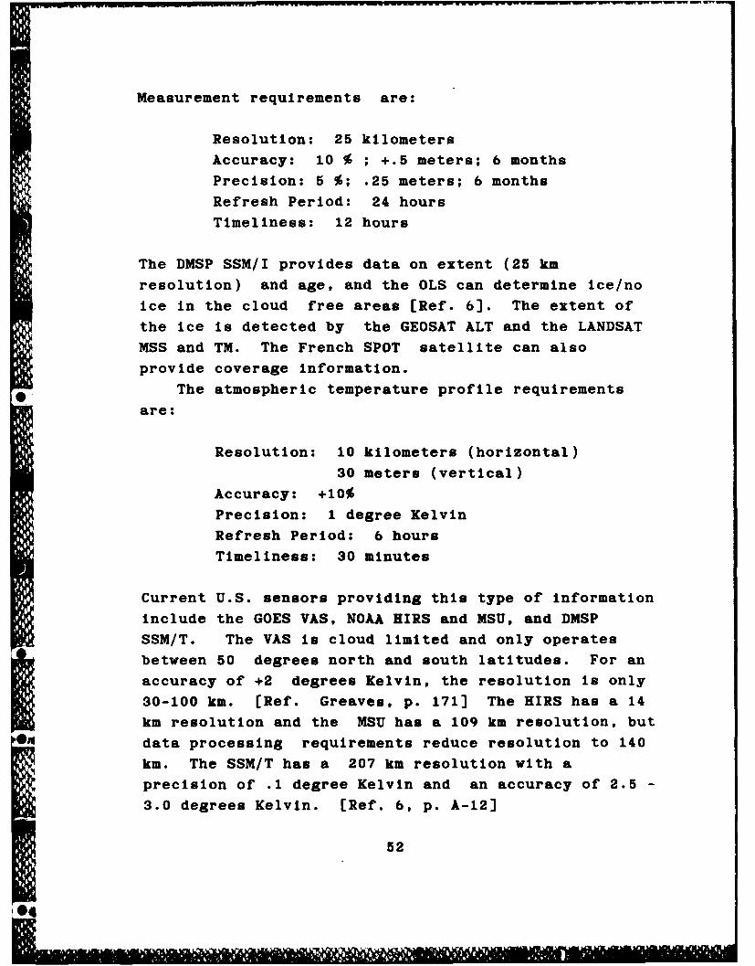
Measurement requirements are:
Resolution: 25 kilometers
Accuracy: 10 % ; +.5 meters; 6 months
Precision: 5 %; .25 meters; 6 months
Refresh Period: 24 hours
Timeliness: 12 hours
The DMSP SSM/I provides data on extent (25 km
resolution) and age, and the OLS can determine ice/no
Ice in the cloud free areas [Ref. 6]. The extent of
the ice is detected by the GEOSAT ALT and the LANDSAT
MSS and TM. The French SPOT satellite can also
provide coverage information.
The atmospheric temperature profile requirements
are:
Resolution: 10 kilometers (horizontal)
30 meters (vertical)
Accuracy: +10%
Precision: 1 degree Kelvin
Refresh Period: 6 hours
Timeliness: 30 minutes
Current U.S. sensors providing this type of information
include the GOES VAS, NOAA HIRS and MSU, and DMSP
SSM/T. The VAS is cloud limited and only operates
between 50 degrees north and south latitudes. For an
accuracy of +2 degrees Kelvin, the resolution is only
30-100 km. [Ref. Greaves, p. 171] The HIRS has a 14
km resolution and the MSU has a 109 km resolution, but
data processing requirements reduce resolution to 140
km. The SSM/T has a 207 km resolution with a
precision of .1 degree Kelvin and an accuracy of 2.5 -
3.0 degrees Kelvin. [Ref. 6, p. A-121
52
I 11 .I4'I !

The atmospheric humidity profile requirements are:
Resolution: 5 kilometers (horizontal)
30 meters (vertical)
Accuracy: +10%
Precision: +.3 grams/cubic meter
Refresh Period: 1 hour
Timeliness: 30 minutes
U.S. sensors retrieving this data include the NOAA HIRS
and the DMSP SSM/T. HIRS does not meet the resolution
requirements. The SSM/T has a 40 km horizontal
resolution and a 2 km vertical resolution. Its
accuracy is 2.5 Kg/square meter. [Ref. 36]
Cloud coverage data requirements are:0
Resolution: .5 kilometers
Accuracy: +.5 %
Precision: +5 %
Refresh period: On call
Timeliness: 4.8 minutes
Many satellites look at cloud coverage, including the
GOES VAS, DMSP OLS, NOAA AVHRR and the foreign
geostationary satellites GMS, INSAT, and METEOSAT.
OLS can almost meet the resolution requirements using
its fine mode (.55 km resolution). Other satellites
* do not have the high resolution required.
Three types of currents are of interest to the
Navy: near shore currents, ocean surface currents and
ocean current profile. Requirements for near shore
currents are:
Resolution: 10 meters
Accuracy: +.1 meter/second, +10 degrees
53

Precision: same as accuracy
Refresh period: 3 hours
Timeliness: 30 minutes
The high resolution Is required to support navalwarfare areas like amphibious warfare, special
operations and logistics. No existing sensor can meet
that requirement.
For ocean surface currents, the requirements are
less stringent:
Resolution: 10 kilometers
Accuracy: +.1 meter/second, 10 degrees
Precision: same as accuracy
Refresh period: 12 hours
Timeliness: 3 hours
The GEOSAT ALT, GOES VAS, LANDSAT TM all provide dataon ocean currents. The OLS on DMSP can detect majorcurrents (direction only) and It meets the all the
above requirements but It Is cloud limited.
The ocean current profile, like the ocean verticaltemperature profile, Is not detectable by existing
sensor technology.
Ocean optical profiles (extinction and scattering)are not specified by requirements such as resolution,
precision, etc. Optical Imagers provide partialinformation on the extinction profile, but no sensor
currently provides Information on the scattering
profile.
Requirements for visibility are:
Resolution: 5 kilometers
Accuracy: +.5 kilometers
Precision: N/A
54
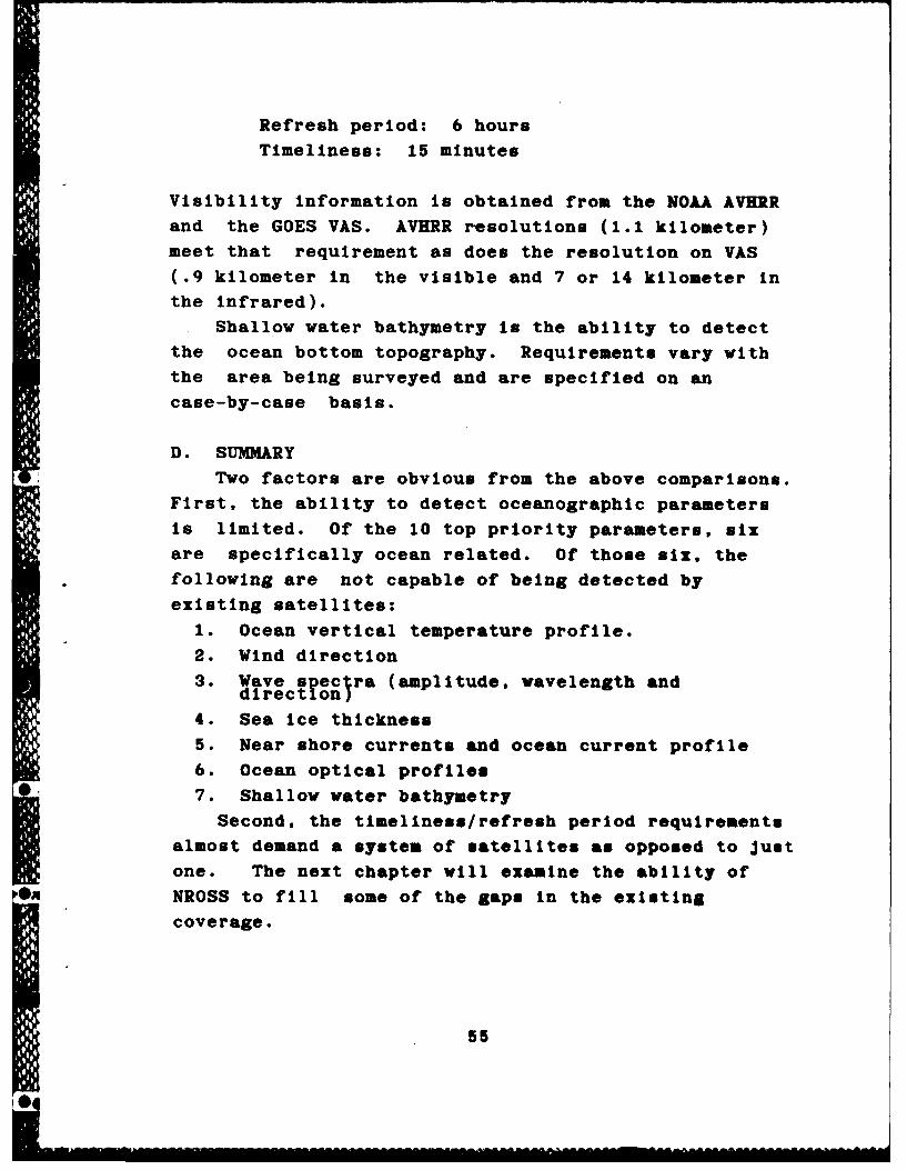
Refresh period: 6 hours
Timeliness: 15 minutes
Visibility Information is obtained from the NOAA AVHRR
and the GOES VAS. AVHRR resolutions (1.1 kilometer)
meet that requirement as does the resolution on VAS
(.9 kilometer in the visible and 7 or 14 kilometer In
the infrared).
Shallow water bathymetry is the ability to detect
the ocean bottom topography. Requirements vary with
the area being surveyed and are specified on an
case-by-case basis.
D. SUMMARY
Two factors are obvious from the above comparisons.
First, the ability to detect oceanographic parameters
is limited. Of the 10 top priority parameters, six
are specifically ocean related. Of those six, the
following are not capable of being detected by
existing satellites:
1. Ocean vertical temperature profile.
2. Wind direction
3. Wave spectra (amplitude, wavelength anddirect on
4. Sea Ice thickness
5. Near shore currents and ocean current profile
6. Ocean optical profiles
7. Shallow water bathymetry
Second, the timeliness/refresh period requirements
almost demand a system of satellites as opposed to Just
one. The next chapter will examine the ability of
Sn NROSS to fill some of the gaps In the existing
coverage.
55

VI. THE NAVY REMOTE OCEAN SENSING SYSTEM (NMOSS)
A. INTRODUCTION
The Navy has sponsored Investigations of the
microwave radlometric properties of the ocean and
atmosphere since the early fifties. Starting with
basic research Into properties of the sea surface, the
Navy progressed to planning, developing and using
satellites. The first attempt at developing an
oceanographic satellite was the Remote Ocean Surface
Measurement System (ROMS). Although ROMS was not
built, the technology for It directly contributed to
subsequent systems. This chapter will examine the most
recent Navy Initiative Into remote sensing of the ocean
from space, the Navy Remote Ocean Sensing System
(NROSS).
B. NIOSS MISSION AND PARTICIPANTS
NROSS was originally conceived following the demise
of NOSS to become the polar orbiting oceanographic
satellite system of the 1980's. It will use existing
sensor technology, a NOAA/DMSP satellite bus, the
established DMSP ground sites (for housekeeping and
data relay), and the soon to be operational TESS 3
(for direct read out to the fleet). It will be an
economically feasible satellite designed to meet
operational requirements using existing technology and
support systems. The mission of NROSS is "the
operation of a remote ocean sensing system that will
routinely supply specific global oceanographic data
under all weather conditions to military and civilian
operational users." [Ref. 46] See Figure 6.1.
56
0

LOW FREQJuENCYMICROWAVE RADIOMETERREFLECTOR
MICROWAVE IMAGER
RADIOMETER
PAYLOAO MOMENTUMCOMPEN4SATION WHEELS
DOPPLER BEACON
ALTIMETER
5-0489
FIGURE 6.1
NAVY REMOTE OCEAN SENSING SYSTEM (NROSS)
(Ref. 46, p. 2-5)
57
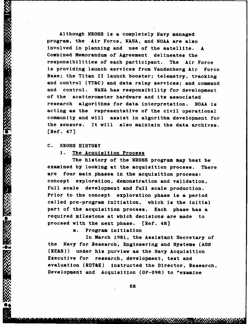
Although NROSS is a completely Navy managed
program, the Air Force, NASA, and NOAA are also
involved in planning and use of the satellite. A
Combined Memorandum of Agreement delineates theresponsibilities of each participant. The Air Force
is providing launch services from Vandenberg Air Force
Base; the Titan II launch booster; telemetry, tracking
and control (TT&C) and data relay services; and command
and control. NASA has responsibility for development
of the scatterometer hardware and its associated
research algorithms for data interpretation. NOAA is
acting as the representative of the civil operational
community and will assist In algorithm development for
the sensors. It will also maintain the data archives.
[Ref. 47)
C. NROSS HISTORY
1. The Acquisition Process
The history of the NROSS program may best be
examined by looking at the acquisition process. There
are four main phases In the acquisition process:
concept exploration, demonstration and validation,
full scale development and full scale production.
Prior to the concept exploration phase Is a period*called pre-program Initiation, which is the Initial
part of the acquisition process. Each phase has a* required milestone at which decisions are made to
proceed with the next phase. [Ref. 48)
a. Program initiation
In March 1981, the Assistant Secretary of
I-On the Navy for Research, Engineering and Systems (ASN
(RE&S)) under his purview as the Navy Acquisition
Executive for research, development, test and
evaluation (RDT&E) instructed the Director, Research,
Development and Acquisition (OP-098) to "examine
58U

affordable options to satisfy Navy requirements for
satellite measurements of oceanographic parameters in
fiscal year 1983 and beyond." [Ref. 49] This request
started the NROSS pre-program Initiation phase.
During this phase, a mission area analysis
Is conducted and a tenative operational requirement Is
developed. Preparations are made for a milestone 0
review. At this review, the decision Is made to
initiate the concept exploration phase, the program is
assigned an acquisition category (ACAT) and a program
element number to begin the funding process [Ref. 48].
With the NOSS experience still fresh, the Director,
Naval Oceanography Division (OP-952) quickly responded
with the proposal for NROSS. The concept was briefed
to the Director, Research, Development and Acquisition
(OP-098) in June 1981, and the Chief of Naval
Operations was briefed In August 1982. [Ref. 49]
In January 1983, ASN (RE&S) declared NROSSto be an ACAT 11S program. An ACAT IIS designation
indicates that the total program costs are expected to
exceed $100 million for RDT&E and/or $500 million for
procurement (in 1980 dollars) or the program is of
special Interest to the Secretary of the Navy
(SECNAV). Additionally, the designation of the
aquisition category was one of the steps to achieving
milestone 0. Approval to proceed beyond milestone 0
came in May 1983 when NROSS was funded as a "new
start" program for fiscal year 1985. [Ref. 49]
b. Concept Exploration
The concept exploration phase follows
milestone 0, and includes the examination andselection of the most promising concept to proceed to
Im the next phase. The program manager Is named and a
program management office (PMO) is established. An
acquisition strategy is created, and two documents are
59
prepared for the milestone I review: the draft Test
and Evaluation Master Plan (TEMP) and the Navy
Decision Coordinating Paper (NDCP). The NROSS program
was Identified as an oceanography initiative In July
1984 and continued funding support was directed for
fiscal year 1986 and beyond.
On 24 May 1984 SECNAV signed the Combined
Memorandum of Agreement (MOA) between the Department of
the Navy and the three other participating agencies
concerning the development and operation of NROSS.
This was a significant event because the Navy could
not afford to provide sole funding for NROSS. Later
that month on 29 May, the NDCP was approved and
progress beyond milestone I to the demonstration and
validation phase of the acquisition process began.
c. Demonstration and Validation
During the demonstration and validation
phase, more refined analysis is done to demonstrate
the technology and critical issues are resolved.
Specifications are written, the TEMP is approved, and
the NDCP and the acquisition strategy are updated.
(Ref. 48]
In December 1985 ASN (RE&S) directed that
NROSS be a competitive procurement rather than sole
source In accordance with the Competition in
Contracting Act of 1984. This encouraged other
companies to respond to the NROSS request for
proposal. A fixed price type contract was specified
on 21 March 1986 and the Navy wa, directed to Identify
funds In the program objective memorandum (POM) for
1988 to purchase one satellite. (Ref. 49]
d. Milestone II Review
The Milestone II review In critical in any
system acquisition, but especially in the case of a
satellite program. For a satellite procurement,
60

successful completion of this review constitutes
approval to develop and build the first satellite. In
preparation for the milestone II Navy Program Decision
Meeting (NPDM) on 18 November 1986 several documents
were prepared. One of these, the updated NDCP,
discussed the subject of NROSS affordability:
NROSS grotram cost estimates...are dependent onthe so rce selection decision for the competitiveDrocurement of the spacecraft and subsystems...andi11l noi be announced until the NPDM fot Milestone
II. [Ref. 49]
In fact, at the NPDM a cost overrun of S150 million
was identified and ASN (RE&S) instructed the Navy to
eliminate the excess.
e. NROSS Cancelled
The Navy responded with three options,
which were presented on 11 December 1986:
1) Find the money to continue the program.
2) Delete the owrequency microwaveradiometer (LFMR) from the sensor suite andcontinue the program at reduced cost.
3) Cancel the program. (Ref. 50]
After reviewing the choices, ASN (RE&S) decided to
cancel the program. As a Milestone II decision
requires SECNAV approval, on 15 December 1986 the
decision was briefed to SECNAV, who concurred.
NROSS, like Its predecessor NOSS, was cancelled.
2. Reaction to NROSS Cancellation
The cancellation of NROSS received negative
publicity In several defense publications (Defense
News, Navy Times and Aviation Week to name a few) and
the other participants In the program expressed their
displeasure. NASA Chief James Fletcher, In a
memorandum to Deputy Secretary of Defense William TaftIV, stated:
T he assut1n that there oul b? an NROSS haseen a cric factor In develo nn our own plansor condutn ocano ~jhi FsagarU fom space.ne canceylaifon o N1618 woUf result Inle!fia o,, o? motn oceanographicdaa
61

In February 1987, SECNAV discussed an alternative
plan with the Secretary of the Air Force. NROSS
sensors would be incorporated Into the Air Force
Defense Meteorological Satellite Program (DMSP) and
the Navy would pay the engineering costs for the
implementation. This plan did not Include the LFMR.
(Ref. 51]
3. NROSS Revived
Meanwhile, efforts were continuing to get the
NROSS program reinstated. The Office of Naval
Research Oceanographic Division submitted a proposal
to SECNAV identifying money from a research and
development account that could be used to restart the
program. In late February, SECNAV agreed to
reconsider his decision, and on 30 March 1987 NROSS
was reborn [Ref. 52]. None of the instruments were
eliminated from the original sensor suite but cost
reductions were stipulated. The reduced costs were to
be achieved by using a capped development environment
[Ref. 53].
a. Guidelines for Restart
In a 10 April 1987 memorandum to CNO,
SECNAV directed that the resuscitated program follow
several guidelines:
1) The restart was for the acquisition of asingle spacecraft.
2) NROSS w _spj Tjd to ACAT I with a costcap of 5335 El!lon.
3) The 1985 Combined MOA would be adhered to.
4) All orininal capabilities, especially theLFMR, wfiuld be provided.
5) The NROSS PMO would be at the $ mdNaval Warfare Systems Command (SPAWAIRef. 54J
The PMO had been decimated when NROSS was
cancelled, with only the Program Manager remaining.
All outyear funding for 1ROSS was removed from the
62

Five Year Defense Plan (1988-1993). When the program
was restarted in March 1987, mimimal 1987 fiscal year
funding remained, as most funds had been re-allocated
when the program was cancelled. [Ref. 53]
b. Current Status
As of September 1987, the PMO is beginning
to recoup Its losses. The Navy Milestone II Decision
Coordinating Meeting is scheduled for October to be
followed by a Defense Acquisition Board (DAB) Review
in November. If all goes well, the Defense
Acquisition Executive will receive the NROSS Decision
Coordinating Paper for approval before the end of this
year. Contract award Is scheduled for mid-1988, and
spacecraft delivery is expected approximately 42
months later. Pending adequate funding, latest launch
estimates put NROSS in orbit by early 1992. [Ref. 53]
D. NROSS INSTRUMENTATION
NROSS will carry a sensor suite of four microwave
instruments: a scatterometer (NSCAT), an altimeter
(ALT), a low frequency microwave radiometer (LFMR) and
a special sensor microwave Imager (SSM/I). Use of the
microwave region will provide NROSS with an
all-weather capability. With the exception of the
LFMR, the selected sensors are all derived from proven
instruments which have been successfully deployed in
space. [Ref. 46] See Table 6.1.
The altimeter is an active instrument similar to
the one flown on SEASAT and currently flying on
GEOSAT. The NROSS altimeter will reflect the
improvements learned from the GEOSAT mission.
The one meter diameter antenna on ALT will operate
at 13.6 GHz and measure the area directly beneath the
satellite. It will measure information on significant
wave height, ocean topography, wind speed, and ocean
63
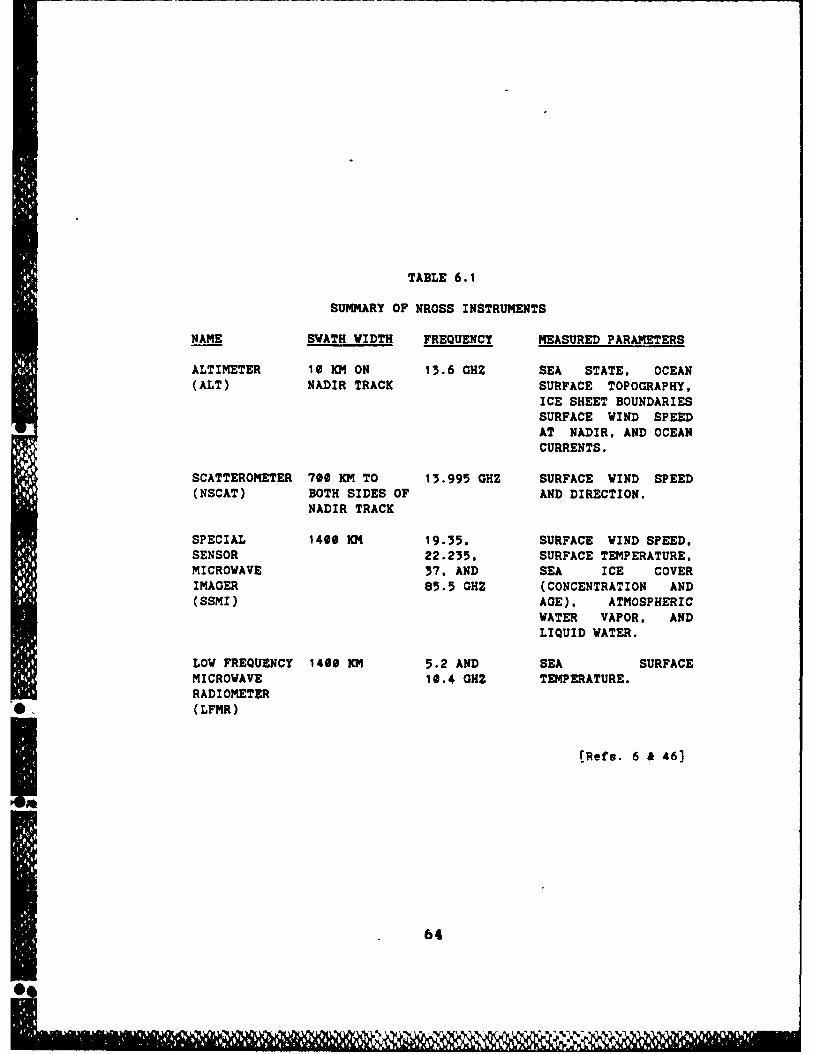
TABLE 6.1
SUMMARY OF NROSS INSTRUMENTS
NAME SWATH WIDTH FREQUENCY MEASURED PARAMETERS
ALTIMETER 10 KM ON 13.6 OHZ SEA STATE, OCEAN(ALT) NADIR TRACK SURFACE TOPOGRAPHY,
ICE SHEET BOUNDARIESSURFACE WIND SPEEDAT NADIR, AND OCEANCURRENTS.
SCATTEROMETER 700 KM TO 13.995 GHZ SURFACE WIND SPEED(NSCAT) BOTH SIDES OF AND DIRECTION.
NADIR TRACK
SPECIAL 1400 KM 19.35. SURFACE WIND SPEED,SENSOR 22.235. SURFACE TEMPERATURE,MICROWAVE 37, AND SEA ICE COVERIMAGER 85.5 GHZ (CONCENTRATION AND(SSMI) AGE), ATMOSPHERIC
WATER VAPOR, ANDLIQUID WATER.
LOW FREQUENCY 1400 KM 5.2 AND SEA SURFACEMICROWAVE 10.4 OHZ TEMPERATURE.RADIOMETER(LFMR)
[Refs. 6 & 46]
64
-- 1114"

fronts and eddies. It will be able to detect
significant wave height to an accuracy of +.5 meters
or 10 % with a 25 km resolution, and it will be able
to detect altitude of the spacecraft to within 25 cm.
[Ref. 49]
NASA is developing and building the second active
sensor, the scatterometer. It is based on the 1978
SEASAT scatterometer. NSCAT will fly six fan beam
antennas vice the four flown on SEASAT. It will
operate at 13.995 GHz and provide Information on
global wind speed (+ 2.0 m/s accuracy at 25 km
resolution) and direction (within 20 degrees accuracy
at 25 km resolution). The additional two antennas
will help resolve the directional ambiguities
encountered in the SEASAT data. [Ref. 55]
The two remaining NROSS instruments, the SSM/I and
the LFMR, are passive radiometers with rotating
antennas. A radiometer Is an instrument that measures
the upwelllng radiation from the earth's surface.
The SSM/I on NROSS will have a parabolic reflecting
antenna that will operate at four frequencies: 19.35,
22.235, 37.0 and 85.5 GHz. SSM/I measurements are all
at a 25 km resolution and can provide information on
ocean surface wind speeds, sea ice conditions (ice
edge to an accuracy of +12.5 km), precipitation
intensity (to within 5.0 mm/hour), water content (both
liquid water, at an accuracy of 2.0 kg/square meter
and water vapor, at an accuracy of .1 kg/square meter)
and soil moisture. The sensor is identical to the one
currently flying on DMSP F8. Data from that
instrument will be used to test and modify existing
algorithms and the sensor will act as a testbed for
the SSM/I to be launched on NROSS. [Ref.49)
The NROSS instrument with the highest technological
risk i the LFMR. A new design, It will carry a very
65

large antenna (approximately six meters in diameter)
to achieve desired resolutions. As mentioned earlier,
the LFMR will have a rotating antenna. This may cause
problems with spacecraft stability and could have an
adverse affect on pointing accuracy, so careful
N consideration is being given to the LFMR design.
[Ref. 56]
The LFMR frequency selection is extremely
important. The frequency must be sensitive to sea
surface temperature and not to other environmental
parameters. The most promising frequency range
appears to be from 4 - 6 GHz, with warm water
sensitivity being better at 6 - 10 GHz. Additionally,
use of both horizontal and vertical polarizations
enables better refinement of data. For the NROSS
LFMR, two frequencies (5.2 and 10.4 GHz) will be
sampled using dual polarization. The LFMR will
retrieve data on brightness temperature to an accuracy
of 1.0 degree Celsius with sufficient resolution to
allow creation of global synoptic maps of sea surface
temperature. [Ref. 56)
E. SUMMARY
NROSS, when launched, will allow real time
oceanographic data distribution to the fleet. Its
sensors were selected to provide the most
oceanographic data for the least technological risk
and cost. No single sensor can provide all of the
required data, so NROSS will fly a suite of
instruments to cover existing gaps. The next chapter
will look to the future of NROSS and Navy abilities toon meet their requirements for oceanographic data from
space.
66
0I

VII. SUMMARY: A LOOK TO THE FUTURE
A. INTRODUCTION
NROSS is a valuable force multiplier, but it
cannot serve the Navy well if it remains on the
ground. It was cancelled once. What will prevent it
from encountering the same fate again? The austere
budget of the early 1980's io even more limited today
due to debt reduction requirements. Satellites are
becoming more expensive. To delay In launching NROSS
any longer risks losing the Navy oceanographic sensing
capability altogether. NROSS is even more valuable
today than when it was first conceived and the Navy
needs it now.
B. A NEW ENVIRONMENT
The U.S. Navy is facing a more formidable threat,
especially from the new Soviet attack submarines. The
Akula, Mike and Sierra SSN's are more quiet than
anticipated and consequently more difficult to detect.
As enemy submarines become less noisy, reliance on
acoustic detection methods will become obsolete. The
trend is shifting from acoustic detection methods to
non-acoustic methods, and remote sensing from space can
assist In the transition. Adm. Carlisle A. H. Trost,
Chief of Naval Operations, has made ASW the Navy's
number one warfighting priority. He believes that
"space-based systems would permit us to know the ocean
environment, including acoustic and radio propagation,
with certainty and totality." [Ref. 57] By providing a
global data base over time, it may be possible to
compare anomalies in the ocean structure to historical
profiles to help determine their cause.
67
The ability of the U.S. and Its allies to place
satellites into orbit was severely hampered by the
grounding of the space shuttle and the Arlane
expendable launch vehicle. Although both systems
should be flying within the next year, launch schedules
for all payloads have been delayed. Priority
satellites will be launched first, and this could
postpone the launch of environmental satellites even
further. Planned oceanographic systems could help the
Navy to meet Its requirements, but their launch dates
are not definite.
The requirements specified in the Satellite
Measurement of Oceanographic Parameters Operational
Requirement (SMOP/OR W0527-OS) back In 1977 have not
been met and are still valid. Oceanographic parameters
identified In Chapter II remain critical to naval
warfare requirements and some have even Increased In
importance with the advent of new weapons systems.
C. COST FACTORS
The cost cap of $335 million placed on 3OSS when
it was revived may appear to some to be an extravagant
amount, but it Is difficult to quantify the benefits
NROSS could provide. A cost effectiveness study
conducted in June 1987 compared the cost of 3OSS to
current collection methods (ships and buoys, and P-3
Orion aircraft with environmental sensors). Three
transits were chosen: A Pacific Ocean Battle Group
crossing, an Atlantic Ocean Battle Group Transit, and
an Atlantic Ocean convoy transit.
, NROSS cost to provide complete support for the
three tracks was $2.951 million. The cost of using P-3
aircraft for the same three tracks was $5.06 mllIon.
Using existing ships and buoy data, the cost was an
extravagant $29.49 million for only 751 of the data
68
NROSS could provide [lor. "5]. Clearly. moss is more
cost effective than existing systems. use of currentsatellites vould be loe expensive. but as shaw In
Chapter V these systems are not capable of meeting
Navy tactical requirements.
D. SUMA IY
3t065 Is a valuable fore maltiplier, but the fleet
operators are not conviaced of the soo. for an
oceanographic system. Vlt ean 306 do for then? At
the very least, it viii provide the varfltias Navy
vith previously available intormation. i could
give a U.S. subwlo the ability to avoid deteetismmore easily; it could alliw more seewate plsement of
ia-situ soustie deteetors ad limit time wastod Insearch areas vith mfavevablo e-e_- re-hit ees ndtioss;
it could aid a battle grw in Its ebility to transit
covertly and it could allow mawe ofoetive ame of ASV
aircraft [Ro. 59. p. is.
13166I i a valid eoseept fr epeuatismaloceenogrphlie satellito to eatI sty navy vfarerequirmmts for mviremmetal data. Its 00moor suite.in eoeert with existing aepetma. will provide thefirst opportunity for gleftl ar-cetisams ceverego
of the vorid°s ooese.
69

LIST OF REFERENCES
1. Draft Navy Remote Ocean Sensing System Test andEvaluation Master Plan (TEMP), Number 968,NUOSS Program Management Office (PMW 142-3),dated 26 June 1986.
2. Watkins, James D., "Space Control is SeaControl," remarks presented at the inaugurationof the Naval Space Command, 1 October 1983.
3. Dictionary of Military Terms: JCS Publication1, U.S. Government Printing Office, 1977.
4. Honhart, David C., "Requirements for Space-Sensed Oceanographic Data," pp. 142-145 inRecent Advances In Civil Space Remote Sensing,The International Society for OpticalEngineering, 1984.
5. McGoldrick, L. F., "Remote Sensing forOceanography: Past, Present, Future," p. 1, inFrontiers of Remote Sensing of the Oceans andTroposphere from Air and Space Platforms, NASAConference Publication 2303, 1984.
6. Brown, Donald N. and McCandless, S. Walter,Plannina and Reference Gulde for NavalOceano raphy from Space (For Official UseOnly), November 1986.
7. Office of Naval Research Space OceanographyGroup, "Navy and Marine Corps Oceanographic andAtmospheric Requirements from Space," chartdated 19 May 1987.
8. Maul, G. A., Introduction to SatelliteOceanograyhy. Martinus Nijhoff, 1985.
9. Haas, I. S. and Shapiro, R., "The NimbusSatellite System: Remote Sensing R&D Platformof the 1970's," pp. 71-95 in MonitoringEarth's Ocean, Land, and Atmosphere from Space-Sensors. Systems, and Applications, Volume 97,American Institute of Aeronautics andAstronautics, Inc., 1985.
10. Horan, J. J., "Space Instruments forOceanography," pp. 239-248 in A Collection ofTechnical Papers--Satellite Applications to
70
Marine Technology, American Institute ofAeronautics and Astronautics, Inc., 1977.
11. Montgomery, D. R. and Wolff, Paul, "Seasat-Aand the Commercial Ocean Community," pp. 276-283 in A Collection of Technical Papers--Satellite Applications to Marine Technology,American Institute of Aeronautics andAstronautics, Inc., 1977.
12. Elachl, C., Cimino, J., and Granger, J.,"Remote Sensing of the Earth with SpacebourneImaging Radars," pp. 639-683 in MonItorlnKEarth's Ocean, Land, and Atmosphere from SDace-Sensors. Systems. and Applications, Volume 97,American Institute of Aeronautics andAstronautics, Inc., 1985.
13. Apel, John R., "A Survey of Some RecentScientific results from the Seasat Altimeter,"pp. 326-334 In Satellite Microwave RemoteSensing, Ellis Horwood, Ltd., 1983.
14. Pierson, Willard J., "Winds over the Oceans asmeasured by the Scatterometer on SEASAT," pp.563-571 In Oceanonraphv from Space, PlenumPublishing Corp., 1981.
15. Taylor, P. K., "The Scanning multichannelmicrowave radlometer--an assessment," pp. 463-477 In Satellite Microwave Remote Sensing,Ellis Horwood, Ltd., 1983.
16. Gower, J. F., "A Review of SEASAT," pp. 14-44In Satellite Microwave Remote Sensing, EllisHorwood, Ltd., 1983.
17. Born, G. H., Lalne, D. B., and Rygh, P.J., "ASurvey of the Goals and Accomplishments of theSEASAT Mission," pp. 3-14 In Oceanography fromSpace, Plenum Publishing Corp., 1981.
18. Bender, Eric, "A National Oceanic SatelliteSystem," Sea Technology, April 1980, pp. 18-22.
19. "Defense Forges Ahead in Budget Sweepstakes,"Sea Technology, March 1980, pp. 18-22.
20. "NOSS sensors scheduled to be included inDefense Satellites," Sea Technoloy.L August1981, pp. 64-65.
71

21. Barrett, E. C., and Curtis, L. F., Introductionto Environmental Remote SensingR Chapman andHall, 1982.
22. National Aeronautics and Space Administrationand National Oceanic and AtmosphericAdministration, Aeronautics and Space Report ofthe President: 1985 Activities. U.S. GovernmentPrinting Office, 1985.
23. Gomberg, Louis and McElroy, S. M., "RemoteSensing of the Earth vith the DefenseMeteorological Satellite," pp. 96-122 InMonitorina Earth's Ocean, Land, and Atmospherefrom Space-Sensors. Systems, and ADyllcatlons.Volume 97, American Institute of Aeronauticsand Astronautics, Inc., 1985.
24. Meyer, Walter D., "The Defense MeteorologicalSatellite Program: a Review of its Impact," pp.129-149 in Monitorinn Earth's Ocean, Land, and
AtmosDhere from Space-Sensors. Systems, andApplications, Volume 97, American Institute ofAeronautics and Astronautics, Inc., 1985.
25. Snow, Rick and Higgins, John, "The TacticalEnvironmental Support System TESS(3),"presented at the Naval Postgraduate SchoolMR4520 Advanced Remote Sensing Course, 4 June1987.
26. Greaves, J. R., and Shenk, V. E., "TheDevelopment of the Geosynchronous WeatherSatellite System," pp.150-181 In Moto nEarth's Ocean. Land. and Atmosuhere Eros Space-
- , Sensors, Sysatems. and Applications.,Volue 97,American Institute of Aeronautics and
Astronautics, Inc., 1985.
27. Schnapf, Abraham, "The TIROS MeteorologicalSatellites--Twenty five years: 1960-1985," pp.51-70 In .trn Eat's Oci !Lad
c~! .Volume 97, ercan nttute oferonaut cs and Astronautics, Inc., 1985.
28. Movle, Edvard V., "LANDSAT D and D'--theOperational Phase of Land Remote Sensing fromSpace," pp. 349-370 In_
72

Institute of Aeronautics and Astronautics,Inc.. 1985.
29. Honvault, Claude, *The Operational MeteosatProgram," pp. 483-492 In Monitorinz Ea tb'sOcean. Land, and Atmosbhere from Space-Sensors.S-ystems. and Applications, Volume 97,* AmericanInstitute of Aeronautics and Astronautics,Inc., 1985.
30. RaJan, Y. S., "Remote Sensing Activities inIndia - Past, Present and Future," pp. 621-636
Atmosphere froa *c-fengors, sremos, andApplications, Volu~me 97 Aerican Institute ofAeronautics and Astronautics, Inc., 1965.
31. Homma. Masanori. and others, 'GoostationaryMeteorological Satellite System in Japan." pp.
enaultICS and Astronautics, Inc., 1985.
32. Kusanagi. M., and others, "Marine Observation
atrenautics Inc1," 1p596 In
33 ortofis. Mnihe and Vel Gibet Te SPOT
Astronautics, Inc., 1965.
34. 'lc tolaMche lanh Weills. Gibr,"TeSOSatellite Mays1967," p. 1. - I oltr
3.berhart, Inst'tti int orit-thnn
NASA way,' Baiance News. 23 May 1957, p. 336.
36. National Aeronautics and Space Administrationand National Oceanic and Atmospheric
73

37. Baker, Simon, *France Rides High," SpcMarkets. Sumer 1987, pp. 73-77.
38. Owen, Kenneth, "Partners Haggle over SpaceStation." Aerospace AmericA. May 1987, p. 10.
39. "Current Earth Observation Programe@ - Aworldwide Overview," Earth Ok servat ionQuarterly. June 1987,. pp. 1 3.
40. Duchossois, G., "ERS-1: Mission Objectives andSystem Description,"
pp.53-55 in
Astronautics, Inc., 1985.
41. "Canada approves development of scaled backRADARSAT," Aviatigg Ink and Space Techknoloat13 July 1967, pp. 51-53.
42. lorikawa, Yasushi, *Studies on Japanese Earth
Astronautics, Inc., 1,.
43. Sherman. John V., "Civil Oceanic Remote SensingNeeds." pp. 149-154 In ae$Ayue J
Socity fr Opica Engneerng,1964.
44. Suomi, Verner Z.. "Sone possibilities on anObserving System for the World ClimateProgram," pp. $05-546 In DIto
Astronautics, Inc., 1965.
45. Train. W.I. and others, "The Navy OKOSAT
Mission Radar Altimeter Satellite Pro raw," pp.
Xeron0-uaile and Astronautics, Inc., 1965.
46. 9A"&&n nigMte iso&I Daft, Nval esearoh Lab.
74

47. Navy Remote Ocean Sensing System (NROSS)
Memorandum of Agreement (MOA), 2 August 1985.
48. Navy Proaram Manager's Guide. 1987.
49. Chief of Naval Operations Letter: Serial 943Dto Space and Naval Warfare Systems Command,Subject: Navl Remlote Ocean Sensing SystemMNOSS) Navy Dec ision Coordinatina Paper. 10Nov 1986.
50. Eisenstadt, Steven, "Navy Scraps Space Plan'sCornerstone." Defense News. 22 December 1986,p. 1.
51. Eisenstadt, Steven, "Lehman Seeks Air ForceHelp In Satellite Program." Navy Times, 23February 1987.
52. Eisenstadt, Steven, "Lohman Reverses Himself,Rethinks Satellite Cancellation Decision,"INav...imesu. 20 April 1987.
53. Holben. Nell, Phone conversation 17 September1987 concerning WROSS program status.
54. Space and Naval Warfare Systems Command (SPAWAR87-48) Navy Remote Sensing System (NROSS) DraftAcquisition Plan, 29 Jun. 1987.
55. LI, F. and others. "NIOSS Scatterometer - AnInstrument for global Oceanic WindObservations," pp. 193-197 in ug.c.eg.t.Avances
ICiil Spas* R2e1t fen -4-. TheI nternational Socit for Ia nineig1984.
56. Bollinger, J. P. and Lo. R. C., "Low FrequencyMicrowave Radiometer for NROSS," pp. 199-207 In
Te International Society for OpticalEngineering, 1984.
57. Trost, Carlisle A. H.. "The Potential of Spaceand Anti-Submarine Warfare," Defense Issues.LVolume 12. Number 41. 1987.
58. Office of Naval Research letter: Subject:
75

59. Honhart, David C., "NUOSS: A Nev ASVDimension,* U.S. Naval Institute Proceedinal..September 1987, pp. 111-113.
76
INITIAL DISTRIBUTION LIST
No. copies1. Defense Technical Information Center 2
Cameron StationAlexandria, Va. 22304-6145
2. Library, Code 0142 2Naval Postgraduate SchoolMonterey, Ca. 93943-5002
3. Commander 2Naval Space CommandAttn: Code N3Dahlgren, Va. 22448
4. Commander 2United States Space CommandAttn: Technical LibraryPeterson AFB, Co. 80914
5. LT. Cheryl L. Spohnholtz, USN 31316 Hound Chase CirclePensacola, Fla. 32514
6. Commanding OfficerFleet Numerical Oceanographic CenterAttn: LibraryMonterey, Ca. 93943-5006
7. Commanding OfficerNavy Environmental Prediction ResearchFacilitiesAttn: LibraryMonterey, Ca. 93943-5006
8. Commanding Officer 3Navy Environmental Prediction ResearchFacilitiesAttn: Dr. Andreas K. GorochMonterey, Ca. 93943-5006
9. Commanding Officer 1Navy Environmental Prediction ResearchFacilitiesAttn: Sheldon M. LazanoffMonterey, Ca. 93943-5006
77

10. Dr. Thomas Vonder Haar 1CIRA/CSUFoothills CampusFort Collins, Co. 80523
11. Chief of Naval Research 2Attn: CAPT David C. Honhart800 North Quincy StreetArlington, Va. 22217-5000
12. SuperintendentNaval Postgraduate SchoolAttn: Dr. Phil DurkeeMonterey, Ca. 93943-5000
78

EnE
; jb
Top Related