


Languages
Pages
Legal


Actual Size
New from OMRON: A Compact, Smart, New-generation Servo!
R7D-ZP H
R7M-Z -S1/BS1

2
C o n t e n t sFeatures
System Configuration
Components and Functions
AC Servo Driver Specifications
AC Servomotor Specifications
Torque and Rotation Speed Characteristics
Reduction Gear Specifications
Dimensions
I/O Specifications
Startup Operation
Wiring and Operaion Examples
Standard Wiring
Connecting Cables
Model Number Legends
Ordering Guide
2
4
6
8
9
10
11
12
16
18
19
22
23
25
26
Orderly Control Panels!
This Servo’s Definitive Feature!“Just Connect and Run”
Smallest* in the Industry! Use Control Panel Space More Efficiently.
Excels in High-speed, High-precision Applications.
For example, in a board-inspector…
100 W Models
105 130
160
120
35 55
You can take advantage of all of the SMARTSTEP Junior's capabilities by combining the Servo Driver with a CP1H-Y PLC. Maximum re-sponse frequency (com-mand pulse response):
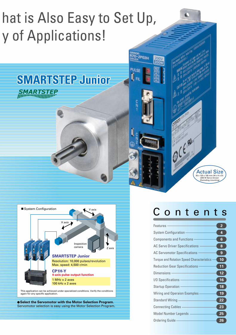
SMARTSTEPSMARTSTEP Junior
Just wire the Servo, set the command pulse type, and turn ON the power to complete the setup. An automatic control function is built-in to provide stable control without difficult settings. The Servo can operate immediately.
Requires less than 1/2 of the volume of the SMARTSTEP Series. Saves space in the control panel.
Can be used easily in a variety of applications, such as conveyors, constant-length feeders, and other feeders.
*Single-phase 200-VAC Units, as of May 2006.
Process Image
SMARTSTEP Junior
Resolution: 10,000 pulses/revolutionMax. speed: 4,500 r/min
CP1H-Y
1 MHz x 2 axes 100 kHz x 2 axes
This application can be achieved under specialized conditions. Verify the conditions again for any specific application.
Z axis
Y axis
X axis
Inspectioncamera
4-axis pulse output function
System Configuration
An Exceptionally Easy-to-Use Servo T hat is Also Easy to Set Up, Compact, and Supports a Wide Variet y of Applications!
Reduced Startup Time!
Just set the command pulse type with the front panel rotary switch.
Just OneSetting
VolumeReduced 60%
Select the Servomotor with the Motor Selection Program.Servomotor selection is easy using the Motor Selection Program.
Actual Size35 x 120 x 105 mm (W x H x D)
(200 W Servo Driver) (Excluding mounting)
CP1H-Y
SMARTSTEP:
250 kpps
SMARTSTEP Junior:
750 kpps
(Excluding mounting)
2
C o n t e n t sFeatures
System Configuration
Components and Functions
AC Servo Driver Specifications
AC Servomotor Specifications
Torque and Rotation Speed Characteristics
Reduction Gear Specifications
Dimensions
I/O Specifications
Startup Operation
Wiring and Operaion Examples
Standard Wiring
Connecting Cables
Model Number Legends
Ordering Guide
2
4
6
8
9
10
11
12
16
18
19
22
23
25
26
Orderly Control Panels!
This Servo’s Definitive Feature!“Just Connect and Run”
Smallest* in the Industry! Use Control Panel Space More Efficiently.
Excels in High-speed, High-precision Applications.
For example, in a board-inspector…
100 W Models
105 130
160
120
35 55
You can take advantage of all of the SMARTSTEP Junior's capabilities by combining the Servo Driver with a CP1H-Y PLC. Maximum re-sponse frequency (com-mand pulse response):
SMARTSTEPSMARTSTEP Junior
Just wire the Servo, set the command pulse type, and turn ON the power to complete the setup. An automatic control function is built-in to provide stable control without difficult settings. The Servo can operate immediately.
Requires less than 1/2 of the volume of the SMARTSTEP Series. Saves space in the control panel.
Can be used easily in a variety of applications, such as conveyors, constant-length feeders, and other feeders.
*Single-phase 200-VAC Units, as of May 2006.
Process Image
SMARTSTEP Junior
Resolution: 10,000 pulses/revolutionMax. speed: 4,500 r/min
CP1H-Y
1 MHz x 2 axes 100 kHz x 2 axes
This application can be achieved under specialized conditions. Verify the conditions again for any specific application.
Z axis
Y axis
X axis
Inspectioncamera
4-axis pulse output function
System Configuration
An Exceptionally Easy-to-Use Servo T hat is Also Easy to Set Up, Compact, and Supports a Wide Variet y of Applications!
Reduced Startup Time!
Just set the command pulse type with the front panel rotary switch.
Just OneSetting
VolumeReduced 60%
Select the Servomotor with the Motor Selection Program.Servomotor selection is easy using the Motor Selection Program.
Actual Size35 x 120 x 105 mm (W x H x D)
(200 W Servo Driver) (Excluding mounting)
CP1H-Y
SMARTSTEP:
250 kpps
SMARTSTEP Junior:
750 kpps
(Excluding mounting)

A1B1A2B2
1
CN2
12
CN1
120
BAA
B00906
PERIHERAL
TOOL ON OFF
RUN OPNERC ERHCOMM
HCP22
IN
OUT
0 1 2 3 4 5 6 78 9 10 110 1 2 3 4 5 6 7
MACHNo.
X10198765432
10
X10098765432
10
INPUT
AC100-240V
L2/N
L1
NC
NC
SYSMAC CJ Series
SYSMAC CS Series
CJ1W-NC113/213/413NC133/233/433
Position Control (NC) Units
Position Control (NC) Units
Controllers
CS1W-NC113/213/413NC133/233/433
C200HW-NC113/213/413
Customizable Counter Unit
CS1W-HCP22-V1
FQM1 Series
Motion Control Module
FQM1-MMP22
SYSMAC CJ1M
SYSMAC CP1H
XW2Z-@@@J-A@
Position Control Cable
Flexible System Configurations for a Varietyof Applications
Pulse Train Command
4 AC Servomotors/Drivers (SMARTSTEP Junior) R7M-Z/R7D-Z

1
2
A
12
34
N
AC Servo Driver AC Servomotor
R7D-ZP@
R7M-Z@
Power Cables
Encoder Cable
Motor power feedback signal
Decelerator
Backlash within 3 minutesR7G-VRSFPB@@@@@@
Backlash within 45 minutesR7G-RGSF@@@@@@
AC ReactorXW2Z-@@@J-B@
XW2B-@@J6-@B
Servo Relay Unit
Servo Driver Cable
R88A-PX5@@@
Motor Power CablesR7A-CAZ0@@S(without brake)R7A-CAZ0@@B(with brake)
R7A-CRZ0@@C
Main Circuit Connector
R7A-CNZ01P
AC Servomotors/Drivers (SMARTSTEP Junior) R7M-Z/R7D-Z 5
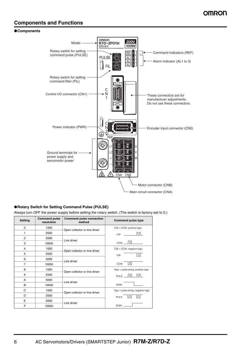
Components and FunctionsComponents
Rotary Switch for Setting Command Pulse (PULSE)Always turn OFF the power supply before setting the rotary switch. (The switch is factory-set to 0.)
SettingCommand pulse
resolutionCommand pulse connection
methodCommand pulse type
0 1000Open collector or line driver
1 2500
2 5000Line driver
3 10000
4 1000Open collector or line driver
5 2500
6 5000Line driver
7 10000
8 1000Open collector or line driver
9 2500
A 5000Line driver
B 10000
C 1000Open collector or line driver
D 2500
E 5000Line driver
F 10000
Command indicators (REF)
Alarm indicator (AL1 to 3)
Encoder input connector (CN2)
Main circuit connector (CNA)
Motor connector (CNB)
Power indicator (PWR)
Rotary switch for settingcommand pulse (PULSE)
Rotary switch for settingcommand filter (FIL)
Control I/O connector (CN1)
Model
Ground terminals for power supply and servomotor power
These connectors are for manufacturer adjustments. Do not use these connectors.
CW + CCW, positive logic
CW
CCW
CW + CCW, negative logic
CW
CCW
Sign + pulse string, positive logic
PULS
SIGN
Sign + pulse string, negative logic
PULS
SIGN
6 AC Servomotors/Drivers (SMARTSTEP Junior) R7M-Z/R7D-Z

Rotary Switch for Setting Command Filter (FIL)This switch does not need to be set if the machine is not subject to vibration. (The switch is factory-set to 0.)
Note 1. Increase the value of the filter setting if there is vibration when starting or stopping.Note 2. The settling time depends on the commanded acceleration/deceleration, the rigidity of the machine motor drive, the encoder resolution, and other factors.Note 3. Use the acceleration/deceleration times as a guideline for determining the Servomotor capacity that can be driven when using STEP commands without com-
manded acceleration/deceleration.
Command Indicators (REF)
Note: The indicator stays lit (yellow) for 1 s when there is a deviation counter reset input.
Alarm Indicators (AL1/AL2/AL3)
Lit: Not lit: Flashing:
Filter setting (See note 1.)
Acceleration/deceleration time
for STEP command (See note 3.)
Approx. time from end of command to end of
positioning (settling time) (See note 2.)
Description
0 45 ms 100 to 200 ms Smaller filter time constant (short posi-tioning time)
Larger filter time con-stant (longer posi-tioning time with little vibration)
1 50 ms 110 to 220 ms
2 60 ms 130 to 260 ms
3 65 ms 150 to 300 ms
4 70 ms 170 to 340 ms
5 80 ms 20 to 400 ms
6 85 ms 250 to 500 ms
7 170 ms 500 to 1,000 ms
8 to F Do not set this switch to 8 to F.
Indicator (See note.) Power to motor Command pulse
Lit orange. OFF None
Flashing orange. OFF Pulse being input.
Lit green. ON None
Flashing green. ON Pulse being input.
Indicator status Alarm Indicator Alarm
Normal
Overcurrent
Overspeed
Servo Driver built-in fan isstopped
Overload
System error
Encoder error
Rotary switch for settingcommand pulse (PULSE)has been changed.
Voltage error
AL2
AL1
AL3
AL2
AL1
AL3
AL2
AL1
AL3
AL2
AL1
AL3
AL2
AL1
AL3
AL2
AL1
AL3
AL2
AL1
AL3
AL2
AL1
AL3
Flashes at a set cycle
AL2
AL1
AL3
AC Servomotors/Drivers (SMARTSTEP Junior) R7M-Z/R7D-Z 7

AC Servo Driver Specifications (R7D-ZP)General Specifications
Control Specifications
Item Specification
Ambient operating temperature 0 to 55°C
Ambient operating humidity 90% max. (with no condensation)
Ambient storage temperature −20 to 70°C
Ambient storage humidity 90% max. (with no condensation)
Storage/operating atmosphere No corrosive gases, dust, iron powder, water drops, or cutting oil
Vibration resistance10 to 55 Hz in X, Y, and Z directions with 0.1-mm double amplitude or acceleration of 4.9 m/s2
max., whichever is smaller
Shock resistance Acceleration 19.6 m/s2 max., in X, Y, and Z directions, three times
Insulation resistance Between power line terminals and FG: 0.5 MΩ min. (at 500 V DC)
Dielectric strengthBetween power line terminals and FG: 1,500 V AC for 1 min at 50/60 HzBetween each control signal and FG: 500 V AC for 1 min
Degree of protection Built into panel (IP10)
International standards
EC Directive
EMC Directive
EN 55011 Class A Group 1EN 61000-6-2
Low voltage Directive
EN 50178
UL Standards UL 508C
cUL Standards cUL C22.2 No.14
Motor capacity 100 W 200 W 400 W 750 W
Servo Driver (R7D-) ZP01H ZP02H ZP04H ZP08H
Item Applicable Servomotor (R7M-) Z10030-S1 Z20030-S1 Z40030-S1 Z75030-S1
Continuous output current (rms) 0.84 A 1.1 A 2.0 A 3.7 A
Momentary maximum output current (rms) 2.5 A 3.3 A 6.0 A 11.1 A
Input power supply (for main circuit and control circuits)
Single-phase 200 to 230 V AC (170 to 253 V), 50/60 Hz
Control method All-digital servo
Inverter method PWM method based on IGBT
Maximum response frequency (command pulse response) 750 kpps
Weight 0.5 kg 1.0 kg
8 AC Servomotors/Drivers (SMARTSTEP Junior) R7M-Z/R7D-Z

AC Servomotor Specifications (R7M-Z)General Specifications
Performance Specifications
Note: Use within the applicable load inertia range. Operation may not be stable outside of this range.
Item Specification
Ambient operating temperature 0 to 40°C
Ambient operating humidity 20% to 80% (with no condensation)
Ambient storage temperature −20 to 60°C
Ambient storage humidity 20% to 80% (with no condensation)
Storage/operating atmosphere No corrosive gases
Vibration resistance10 to 2,500 Hz in X, Y, and Z directions with 0.2-mm double amplitude or acceleration of 24.5 m/s2
max., whichever is smaller
Shock resistance Acceleration 98 m/s2 max., in a vertical direction, two times
Insulation resistance Between power line terminals and FG: 10 MΩ min. (at 500 V DC)
Dielectric strength Between power line terminals and FG: 1,500 V AC for 1 min at 50/60 Hz
Run position Any direction
Insulation grade Type B
Structure Totally-enclosed self-cooling
Degree of protection IP55 (except for through-shaft section)
Vibration grade V-15
Mounting method Flange-mounting
International standards
EC Directive
EMC Directive
EN 55011 Class A Group 1EN 61000-6-2
Low voltage Directive
IEC 60034-1, -5, -8, -9EN 60034-1, -9
UL Standards UL 1004
cUL Standards cUL C22.2 No.100
Applicable Servomotor (R7M-) Z10030-S1 Z20030-S1 Z40030-S1 Z75030-S1
ItemApplicable Servo Driver (R7D-)
Pulse train models ZP01H ZP02H ZP04H ZP08H
Rated output W 100 200 400 750
Rated torque N·m 0.318 0.637 1.27 2.39
Rated rotation speed r/min 3000
Momentary maximum rotation speed
r/min 4500
Momentary maximum torque N·m 0.955 1.91 3.82 7.16
Rated current A (irms) 0.84 1.1 2.0 3.7
Momentary maximum current A (irms) 2.5 3.3 6.0 11.1
Rotor inertiakg·m2
(GD2/4)6.34 × 10−6 3.30 × 10⁻⁵ 6.03 × 10⁻⁵ 1.50 × 10⁻⁴
Power rate kW/s 16.0 12.3 26.7 38.1
Allowable radial load N 78 245 245 392
Allowable thrust load N 54 74 74 147
WeightWithout brake kg 0.5 0.9 1.3 2.6
With brake kg 0.7 1.5 1.9 3.5
Radiator dimensions (material) t6 × @250 (Al)
Applicable load inertia (See note.)
kg·m2 6.0 × 10⁻⁵ (9.5 ×) 3.0 × 10⁻⁴ (9.1 ×) 5.0 × 0−4 (8.3 ×) 1.0 × 10⁻³ (6.7 ×)
Brake Specifi-cations
Brake inertiakg·m2
(GD2/4)7.54 × 10−7 6.4 × 10⁻⁶ 6.4 × 10⁻⁶ 1.71 × 10⁻⁵
Excitation voltage
V 24 VDC ±10%
Power consumption (at 20°C)
W 6 7 7 7.7
Current consumption (at 20°C)
A 0.25 0.29 0.29 0.32
Static friction torque N·m 0.318 min. 0.637 min. 1.27 min. 2.45 min.
Attraction time ms 60 max. 80 max.
Release time ms 30 max. 20 max.
Backlash 1° max.
Rating Continuous
AC Servomotors/Drivers (SMARTSTEP Junior) R7M-Z/R7D-Z 9
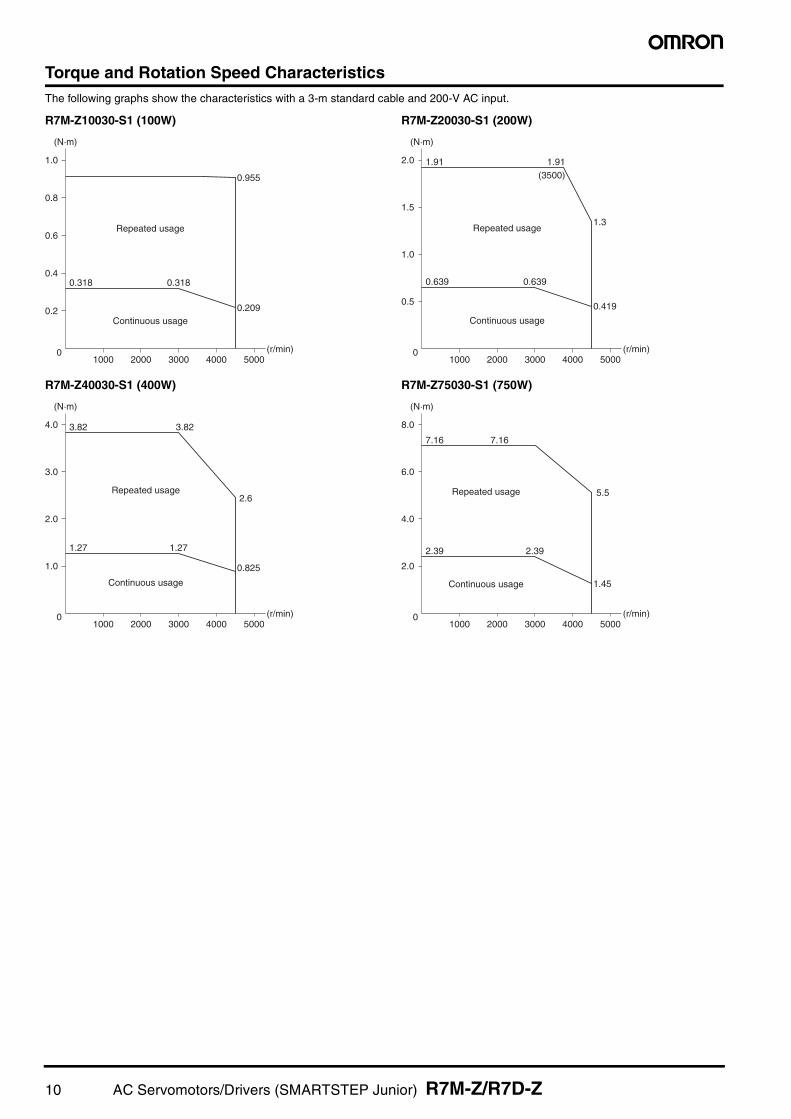
Torque and Rotation Speed CharacteristicsThe following graphs show the characteristics with a 3-m standard cable and 200-V AC input.
R7M-Z10030-S1 (100W) R7M-Z20030-S1 (200W)
R7M-Z40030-S1 (400W) R7M-Z75030-S1 (750W)
0.2
1000 2000 3000
0.3180.318
0.955
0.209
Repeated usage
Continuous usage
4000 50000
0.4
0.6
0.8
1.0
(N·m)
(r/min)
0.5
1.0
1.5
1000 2000 3000
1.91(3500)
0.6390.639
1.3
0.419
4000 50000
2.0 1.91
(N·m)
(r/min)
Repeated usage
Continuous usage
1.0
2.0
3.0
1000 2000 3000
3.82
1.271.27
2.6
0.825
4000 50000
4.0 3.82
(N·m)
(r/min)
Repeated usage
Continuous usage
2.0
4.0
6.0
1000 2000 3000
7.16
2.392.39
1.45
4000 50000
8.0
7.16
(N·m)
(r/min)
5.5Repeated usage
Continuous usage
10 AC Servomotors/Drivers (SMARTSTEP Junior) R7M-Z/R7D-Z
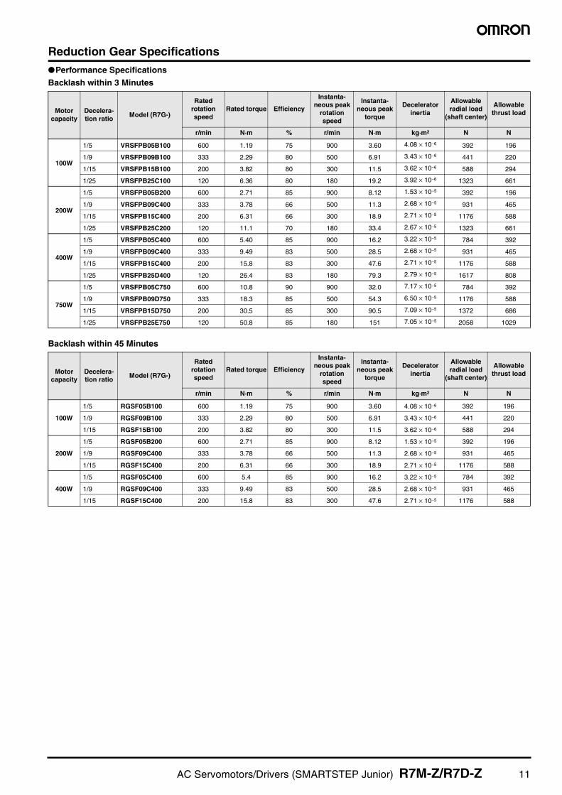
Reduction Gear SpecificationsPerformance Specifications
Backlash within 3 Minutes
Backlash within 45 Minutes
Motor capacity
Decelera-tion ratio
Model (R7G-)
Rated rotation speed
Rated torque Efficiency
Instanta-neous peak
rotation speed
Instanta-neous peak
torque
Decelerator inertia
Allowable radial load
(shaft center)
Allowable thrust load
r/min N·m % r/min N·m kg·m2 N N
100W
1/5 VRSFPB05B100 600 1.19 75 900 3.60 4.08 × 10⁻⁶ 392 196
1/9 VRSFPB09B100 333 2.29 80 500 6.91 3.43 × 10⁻⁶ 441 220
1/15 VRSFPB15B100 200 3.82 80 300 11.5 3.62 × 10⁻⁶ 588 294
1/25 VRSFPB25C100 120 6.36 80 180 19.2 3.92 × 10⁻⁶ 1323 661
200W
1/5 VRSFPB05B200 600 2.71 85 900 8.12 1.53 × 10⁻⁵ 392 196
1/9 VRSFPB09C400 333 3.78 66 500 11.3 2.68 × 10⁻⁵ 931 465
1/15 VRSFPB15C400 200 6.31 66 300 18.9 2.71 × 10⁻⁵ 1176 588
1/25 VRSFPB25C200 120 11.1 70 180 33.4 2.67 × 10⁻⁵ 1323 661
400W
1/5 VRSFPB05C400 600 5.40 85 900 16.2 3.22 × 10⁻⁵ 784 392
1/9 VRSFPB09C400 333 9.49 83 500 28.5 2.68 × 10⁻⁵ 931 465
1/15 VRSFPB15C400 200 15.8 83 300 47.6 2.71 × 10⁻⁵ 1176 588
1/25 VRSFPB25D400 120 26.4 83 180 79.3 2.79 × 10⁻⁵ 1617 808
750W
1/5 VRSFPB05C750 600 10.8 90 900 32.0 7.17 × 10⁻⁵ 784 392
1/9 VRSFPB09D750 333 18.3 85 500 54.3 6.50 × 10⁻⁵ 1176 588
1/15 VRSFPB15D750 200 30.5 85 300 90.5 7.09 × 10⁻⁵ 1372 686
1/25 VRSFPB25E750 120 50.8 85 180 151 7.05 × 10⁻⁵ 2058 1029
Motor capacity
Decelera-tion ratio
Model (R7G-)
Rated rotation speed
Rated torque Efficiency
Instanta-neous peak
rotation speed
Instanta-neous peak
torque
Decelerator inertia
Allowable radial load
(shaft center)
Allowable thrust load
r/min N·m % r/min N·m kg·m2 N N
100W
1/5 RGSF05B100 600 1.19 75 900 3.60 4.08 × 10⁻⁶ 392 196
1/9 RGSF09B100 333 2.29 80 500 6.91 3.43 × 10⁻⁶ 441 220
1/15 RGSF15B100 200 3.82 80 300 11.5 3.62 × 10⁻⁶ 588 294
200W
1/5 RGSF05B200 600 2.71 85 900 8.12 1.53 × 10⁻⁵ 392 196
1/9 RGSF09C400 333 3.78 66 500 11.3 2.68 × 10⁻⁵ 931 465
1/15 RGSF15C400 200 6.31 66 300 18.9 2.71 × 10⁻⁵ 1176 588
400W
1/5 RGSF05C400 600 5.4 85 900 16.2 3.22 × 10⁻⁵ 784 392
1/9 RGSF09C400 333 9.49 83 500 28.5 2.68 × 10⁻⁵ 931 465
1/15 RGSF15C400 200 15.8 83 300 47.6 2.71 × 10⁻⁵ 1176 588
AC Servomotors/Drivers (SMARTSTEP Junior) R7M-Z/R7D-Z 11

Dimensions (Unit: mm)
AC Servomotors
• 100WR7M-Z10030-S1 R7M-Z10030-BS1
• 200W/400W/750WR7M-Z20030-S1/Z40030-S1/Z75030-S1 R7M-Z20030-BS1/Z40030-BS1/Z75030-BS1
Without Brake With Brake
R7M-Z10030-S1 R7M-Z10030-BS1Without Brake With Brake
Shaft end dimensions
94
14 14
Two, 4.3 dia.
46 dia.
40
3
3
1.8
25
30h8 dia.
8h6 dia.
139 25
5 2.55 2.5
30h8 dia.
8h6 dia.
300300
300300
Without Brake With Brake
Dimensions (mm) LLLR
Flange surface Shaft end
Model Without B With B C D1 D2 F G Z S QK
R7M-Z20030-@S1 95.5 135.530 60 70 50h8
3
6Four,
5.5 dia. 14h6 20R7M-Z40030-@S1 118.5 158.5
R7M-Z75030-@S1 133 176 40 80 90 70h8 8Four, 7 dia. 16h6 30
Shaft end dimensions750-W Motor Output Section Dimensions
R7M-Z@@@30-S1 R7M-Z@@@30-BS1Without Brake With Brake
C
3
5
5
D1 dia.
ZMounting holes
D2 dia.
LL LR
G GF
LL LR
D2 dia.S dia.
QKQK
S dia.
F
2
20
300300
300300
12 AC Servomotors/Drivers (SMARTSTEP Junior) R7M-Z/R7D-Z
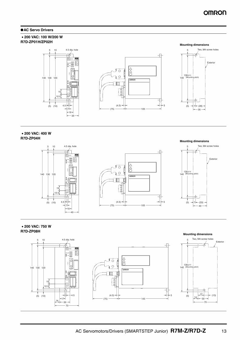
AC Servo Drivers
100WR7D-ZP01HDRIVER
200V
REF
AL1PULSEAL2AL3
CNA
PWR
CNB
U
V
W
L1
L2
+
−
FIL
CN2
CN1
35
105
197
4.5(10) (4.5)
(75)(5) (28)
12.5
15
120130140
5
(5)
130±0.5
140
510 4.5 dia. hole Two, M4 screw holes
35
7
Exterior
5
(Mounting pitch)
• 200 VAC: 100 W/200 WR7D-ZP01H/ZP02H
Mounting dimensions
400W200VR7D-ZP04H
DRIVER
REF
AL1AL2AL3
CNA
PWR
CNB
U
V
W
L1
L2
+
−
PULSE
FIL
CN2
CN1
40
105
197
4.5(10) (4.5)
(75)(5) (33)
12.5
15
120130140
5
(5)
130±0.5
140
510 4.5 dia. hole
40
7
Exterior
Two, M4 screw holes
5
(Mounting pitch)
• 200 VAC: 400 WR7D-ZP04H
Mounting dimensions
750W200VR7D-ZP08H
DRIVER
REF
AL1AL2AL3
CNA
PWR
CNB
U
V
W
L1
L2
+
−
PULSE
FIL
CN2
CN1
(10)(5)
12.5
15
120130140
5 10 4.5 dia. hole
(13)(5)
130±0.5
140
5
1417
30
70145
(4.5)
(75)
5
70
3014
17
4.5
ExteriorTwo, M4 screw holes
(Mounting pitch)
• 200 VAC: 750 WR7D-ZP08H
Mounting dimensions
AC Servomotors/Drivers (SMARTSTEP Junior) R7M-Z/R7D-Z 13
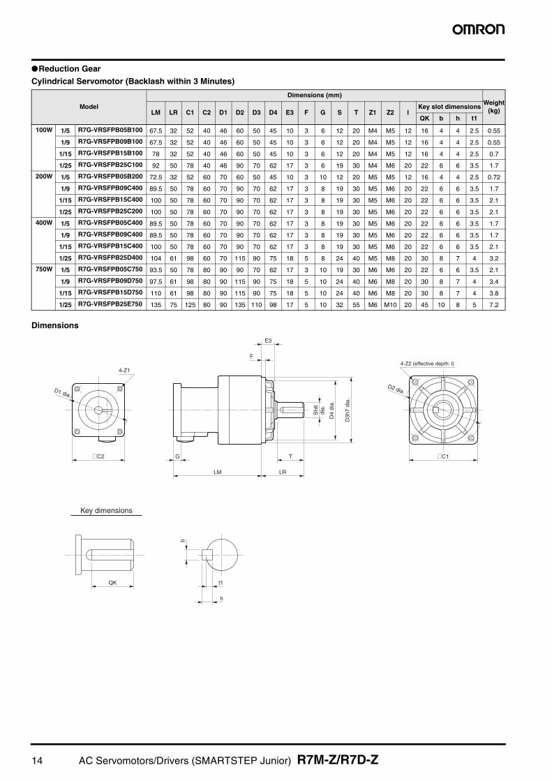
Reduction Gear
Cylindrical Servomotor (Backlash within 3 Minutes)
Dimensions
Model
Dimensions (mm)Weight
(kg)LM LR C1 C2 D1 D2 D3 D4 E3 F G S T Z1 Z2 lKey slot dimensions
QK b h t1
100W 1/5 R7G-VRSFPB05B100 67.5 32 52 40 46 60 50 45 10 3 6 12 20 M4 M5 12 16 4 4 2.5 0.55
1/9 R7G-VRSFPB09B100 67.5 32 52 40 46 60 50 45 10 3 6 12 20 M4 M5 12 16 4 4 2.5 0.55
1/15 R7G-VRSFPB15B100 78 32 52 40 46 60 50 45 10 3 6 12 20 M4 M5 12 16 4 4 2.5 0.7
1/25 R7G-VRSFPB25C100 92 50 78 40 46 90 70 62 17 3 6 19 30 M4 M6 20 22 6 6 3.5 1.7
200W 1/5 R7G-VRSFPB05B200 72.5 32 52 60 70 60 50 45 10 3 10 12 20 M5 M5 12 16 4 4 2.5 0.72
1/9 R7G-VRSFPB09C400 89.5 50 78 60 70 90 70 62 17 3 8 19 30 M5 M6 20 22 6 6 3.5 1.7
1/15 R7G-VRSFPB15C400 100 50 78 60 70 90 70 62 17 3 8 19 30 M5 M6 20 22 6 6 3.5 2.1
1/25 R7G-VRSFPB25C200 100 50 78 60 70 90 70 62 17 3 8 19 30 M5 M6 20 22 6 6 3.5 2.1
400W 1/5 R7G-VRSFPB05C400 89.5 50 78 60 70 90 70 62 17 3 8 19 30 M5 M6 20 22 6 6 3.5 1.7
1/9 R7G-VRSFPB09C400 89.5 50 78 60 70 90 70 62 17 3 8 19 30 M5 M6 20 22 6 6 3.5 1.7
1/15 R7G-VRSFPB15C400 100 50 78 60 70 90 70 62 17 3 8 19 30 M5 M6 20 22 6 6 3.5 2.1
1/25 R7G-VRSFPB25D400 104 61 98 60 70 115 90 75 18 5 8 24 40 M5 M8 20 30 8 7 4 3.2
750W 1/5 R7G-VRSFPB05C750 93.5 50 78 80 90 90 70 62 17 3 10 19 30 M6 M6 20 22 6 6 3.5 2.1
1/9 R7G-VRSFPB09D750 97.5 61 98 80 90 115 90 75 18 5 10 24 40 M6 M8 20 30 8 7 4 3.4
1/15 R7G-VRSFPB15D750 110 61 98 80 90 115 90 75 18 5 10 24 40 M6 M8 20 30 8 7 4 3.8
1/25 R7G-VRSFPB25E750 135 75 125 80 90 135 110 98 17 5 10 32 55 M6 M10 20 45 10 8 5 7.2
Key dimensions
QK
b
h
t1
D1 dia.
4-Z1
@C2
LM
G
LR
T
F
E3
D4
dia.
D3h
7 di
a.
Sh6
di
a.
@C1
D2 dia.
4-Z2 (effective depth: l)
14 AC Servomotors/Drivers (SMARTSTEP Junior) R7M-Z/R7D-Z

Cylindrical Servomotor (Backlash within 45 Minutes)
Dimensions
Model
Dimensions (mm)Weight
(kg)LM LR C1 C2 D1 D2 D3 D4 E3 F G S T Z1 Z2 lKey slot dimensions
QK b h t1
100W 1/5 R7G-RGSF05B100 67.5 32 52 40 46 60 50 45 10 3 6 12 20 M4 M5 12 16 4 4 2.5 0.55
1/9 R7G-RGSF09B100 67.5 32 52 40 46 60 50 45 10 3 6 12 20 M4 M5 12 16 4 4 2.5 0.55
1/15 R7G-RGSF15B100 78 32 52 40 46 60 50 45 10 3 6 12 20 M4 M5 12 16 4 4 2.5 0.70
200W 1/5 R7G-RGSF05B200 72.5 32 52 60 70 60 50 45 10 3 10 12 20 M5 M5 12 16 4 4 2.5 0.72
1/9 R7G-RGSF09C400 89.5 50 78 60 70 90 70 62 17 3 8 19 30 M5 M6 20 22 6 6 3.5 1.7
1/15 R7G-RGSF15C400 100 50 78 60 70 90 70 62 17 3 8 19 30 M5 M6 20 22 6 6 3.5 2.1
400W 1/5 R7G-RGSF05C400 89.5 50 78 60 70 90 70 62 17 3 8 19 30 M5 M6 20 22 6 6 3.5 1.7
1/9 R7G-RGSF09C400 89.5 50 78 60 70 90 70 62 17 3 8 19 30 M5 M6 20 22 6 6 3.5 1.7
1/15 R7G-RGSF15C400 100 50 78 60 70 90 70 62 17 3 8 19 30 M5 M6 20 22 6 6 3.5 2.1
QK
b
h
t1
D1 dia.
4-Z1
@C2
LM
G
LR
T
F
E3
D4
dia.
D3h
7 di
a.
Sh6
di
a.
@C1
D2 dia.
Key dimensions
4-Z2 (effective depth: l)
AC Servomotors/Drivers (SMARTSTEP Junior) R7M-Z/R7D-Z 15

I/O Specifications
Main Circuit Connector Specifications (CNA) R7A-CNZ01P
Main Circuit Connector (CNA) Pin Arrangement
Servomotor Connector Specifications (CNB) R7A-CNZ01A
Main Circuit Connector (CNB) Pin Arrangement
Pin Symbol Name Function
1 L1Main-circuit Power Supply Terminals Single-phase 200/230 V AC (170 to 253 V AC) 50/60 Hz
2 L2
3 + External Regeneration Resistance Unit connection terminals
If regenerative energy is high, connect an External Regeneration Unit between P and N.4 −
Frame ground This is the ground terminal. Ground it to a minimum of 100 Ω (Japanese class D, class 3).
Pin Symbol Name Function
1 U
Servomotor Terminals
RedThese are the terminals for outputs to the Servomotor.Be careful to wire them correctly.
2 V White
3 W Blue
4 − --- Do not connect anything to this terminal. Frame ground Green/Yellow Connect the Servomotor FG terminal.
CNA Connector
Main circuit connector 04JFAT-SBXGF-N (JST Mfg. Co. Ltd.)
200V
FIL
PULSEREFAL1AL2AL3
CN1
CN2PWR
L1
L2
+
CNA CNB
U
V
W−
C
089
AB DEF
45 3267 1
C
089
AB DEF
45 3267 1
A
12
34
N
1
2
3
4
CNB Connector
200V
FIL
PULSEREFAL1AL2AL3
CN1
CN2PWR
L1
L2
+
CNA CNB
U
V
W−
C
089
AB DEF
45 3267 1
C
089
AB DEF
45 3267 1
A
12
34
N
1
2
3
4
Servomotor connector04JFAT-SAYGF-N(JST Mtg. Co., Ltd.)
16 AC Servomotors/Drivers (SMARTSTEP Junior) R7M-Z/R7D-Z

Control I/O SignalsCN1 Control Inputs
CN1 Control Outputs
Note: An open-collector output interface is used for sequence outputs (maximum operating voltage: 30 V DC; maximum output current: 50 mA).
CN1 Connectors (14P)Soldered Connectors
CN2 Encoder Connector Specifications
CN2 Connectors (10P)Crimped Connectors Soldered Connectors
Pin No. Signal name Function Function/interface
1 +CW/PULSReverse pulses, feed pulses
Pulse string input terminals for position commands.Line-driver input: 7 mA at 3 V
Maximum response frequency: 750 kppsOpen-collector input: 7 to 15 mA
Maximum response frequency: 187.5 kppsNote: Either forward and reverse pulses (CW/CCW), or feed pulses and direction signal (PULS/
SIGN) can be selected using the rotary switch for setting command pulses, located on thefront of the Unit.
2 −CW/PULS
3 +CCW/SIGNForward pulses, phase difference signals
4 −CCW/SIGN
5 +24VIN+24-V power supply input for control DC
Power supply input terminal (+24 V DC) for sequence inputs (pin 6).
6 RUN RUN command input ON: Servo ON (Starts power to Servomotor.)
8 +ECRSTDeviation counter reset
ON: Pulse commands prohibited and deviation counter cleared.Line-driver input: 7 mA at 3 VOpen-collector input: 7 to 15 mANote: Input for at least 20 µs.9 −ECRST
Pin No. Signal name Function Function/interface
10 ZPhase Z output
Outputs the Encoder’s phase Z. (1 pulse/revolution)Note: Use the rising edge of the ON signal.11 ZCOM
12 ALM Alarm outputWhen the Servo Driver generates an alarm, the output turns OFF.Note: OFF for approx. 2 s after the power is turned ON.
13 BKIR Brake interlock output Outputs the holding brake timing signals. Release the holding brake when this signal is ON.
14 INP Positioning completed output ON when the position deviation is within ±10 pulses.
7 0GND Output ground common Ground common for sequence outputs (pins 12, 13 and 14).
Name Model Manufacturer
Cable solder plug 10114-3000VESumitomo 3M
Cable case (shell kit) 10314-52A0-008
Pin Symbol Name
1 E5V Encoder power supply +5 V
2 E0V Encoder power supply GND
3 A + Phase A Encoder + phase-A input
4 A − Phase A Encoder − phase-A input
5 + Phase B Encoder + phase-B input
6 − Phase B Encoder − phase-B input
7 Phase Z Encoder phase-Z input
8 Phase U Poll sensor phase U
9 Phase V Poll sensor phase V
10 Phase W Poll sensor phase W
Shell FG Cable shield ground
Name Model Manufacturer
Plug, Cable, and Cover Set 54559-1005
MolexPlug Housing 51209-1001
Crimp Terminal 59351-8187 (Loose wires)
Crimping Tool 57401-5300
Name Model Manufacturer
Plug, Cable, and Cover Set 54599-1005Molex
Plug Connector 51593-1011
AC Servomotors/Drivers (SMARTSTEP Junior) R7M-Z/R7D-Z 17

Startup Operation ExampleThis section presents an example of the SMARTSTEP Junior startup procedure.
In this example a package-type CP1H Programmable Controller is connected.
The no-load operation must always be checked before the Servomotor is connected to the mechanical system.
Startup Flow(1) WiringConnect the power supply, Encoder Cable, Power Cable, and Control Cable.
An example of connecting the Control Cable to the CP1H is shown below.
(2) Setting Command PulsesSet the rotary switch for setting command pulse (PULSE) according to the Controller.
For example, set 3 for a command pulse resolution of 10,000 pulses/rotation and a command pulse type of CW + CCW positive logic.
(Turn OFF the power before setting the rotary switch.)
(3) Completing the SetupTo complete the setup, recheck the power supply voltage and the wiring, and then turn ON the power.
Check the LED indicators to confirm that no alarms have occurred.
A
12
34
N
1
2
3
4
R7M-Z@Servomotors
CP1H Programmable Controller
R7D-ZP@ Servo Driver
R7A-CPZ@@@SControl Cable
R7A-CRZ@@@CEncoder Cable
R7A-CAZ@@@@Motor Cable
R7A-CNZ01PMain circuit connector
Power supply 200 VAC
18 AC Servomotors/Drivers (SMARTSTEP Junior) R7M-Z/R7D-Z

Wiring and Operation ExamplesIn these examples, the SMARTSTEP Junior is operated using the CP1H PLC.
The wiring and operations are shown below.
Example: Connecting to the CP1HThis example shows the Control Cable connection between the SMARTSTEP Junior and the CP1H PLC.
Note 1. This is only a wiring example. Refer to the specific user’s manuals for the actual wiring and PLC allocations for your system.Note 2. Insert a resistance of 1.6 to 2.2 kΩ so that the ECRST input current will be 7 to 15 mA.
1.6 kΩ
24 VDC
24 VDC
CN1
1 +CW2 −CW3 +CCW4 −CCW
8 +ECRST9 −ECRST
5 +24V IN
6 RUN
10 Z11 ZCOM
Shell FG
CP1H-Y20DT-D
Output Terminal
Pulse output 0 CW0+CW0−CCW0+CCW0−
Origin search 0 (Error counter reset)
CIO 101, bit 02
COM CIO 101
Input Terminal
24-VDC input terminal +
24-VDC input terminal −
COM
Pulse 0Origin Input Signal
CIO 1, bit 03
Pulse 0Origin Proximity Input Signal
CIO 1, bit 05
Origin Search CIO 0, bit 01
CW limit detection switch
CIO 0, bit 04
CCW limit detection switch
CIO 0, bit 05
Positioning CIO 0, bit 10
R7D-ZP@
(See note 2.)
AC Servomotors/Drivers (SMARTSTEP Junior) R7M-Z/R7D-Z 19

(1) Operation Example Using the CP1H: Origin SearchAn origin search can be easily executed using the ORG command.
Operation
PLC SetupThe settings for the CP1H PLC Setup are made using the CX-Programmer.
To make new settings, start the CX-Programmer and select File - New and then specify the device name and the device type.
Double-click Setting Icon in the new project to display the PLC Settings Dialog Box. The illustration below shows example settings.
Note: The settings for using origin search and the origin input signal type are read when the power is turned ON.
Ladder Program
When the origin search switch CIO 0.01 is turned ON, an origin search is started and the origin search is executed at high speed.
When the origin proximity input signal turns ON, the origin proximity speed is used.
When the origin proximity input signal turns OFF, the origin search stops at the next origin signal input and the origin search is com-
pleted.
Note: This is only an operation example. Refer to the specific user’s manuals for the actual wiring and PLC allocations for your system. For instructions and sample programs, refer to the CP1H Operation Manual (Cat. No. W450).
0Pulse Output 0Origin Proximity Input (1.05)
Origin search execution 0.01
Pulse Output 0Origin Signal Input (1.03)
Pulse Output 0
Pulse frequency
1
0
1
0
1
CCW CW
Origin search acceleration rate
Origin search initial speed
Origin search deceleration rate
Origin search high speed
Execution of ORG(889) starts. Origin search starts.
Origin search proximity speed
Stop
#0000#0000@ORG
END (001)
Origin search switch 0.01
CCW limit detection switch 0.05
CW limit detection switch 0.04
CCW limit input signal
A540.09
Origin search 0: #0000Origin search and CW/CCW method: #0000
CW limit input signal
A540.08
20 AC Servomotors/Drivers (SMARTSTEP Junior) R7M-Z/R7D-Z
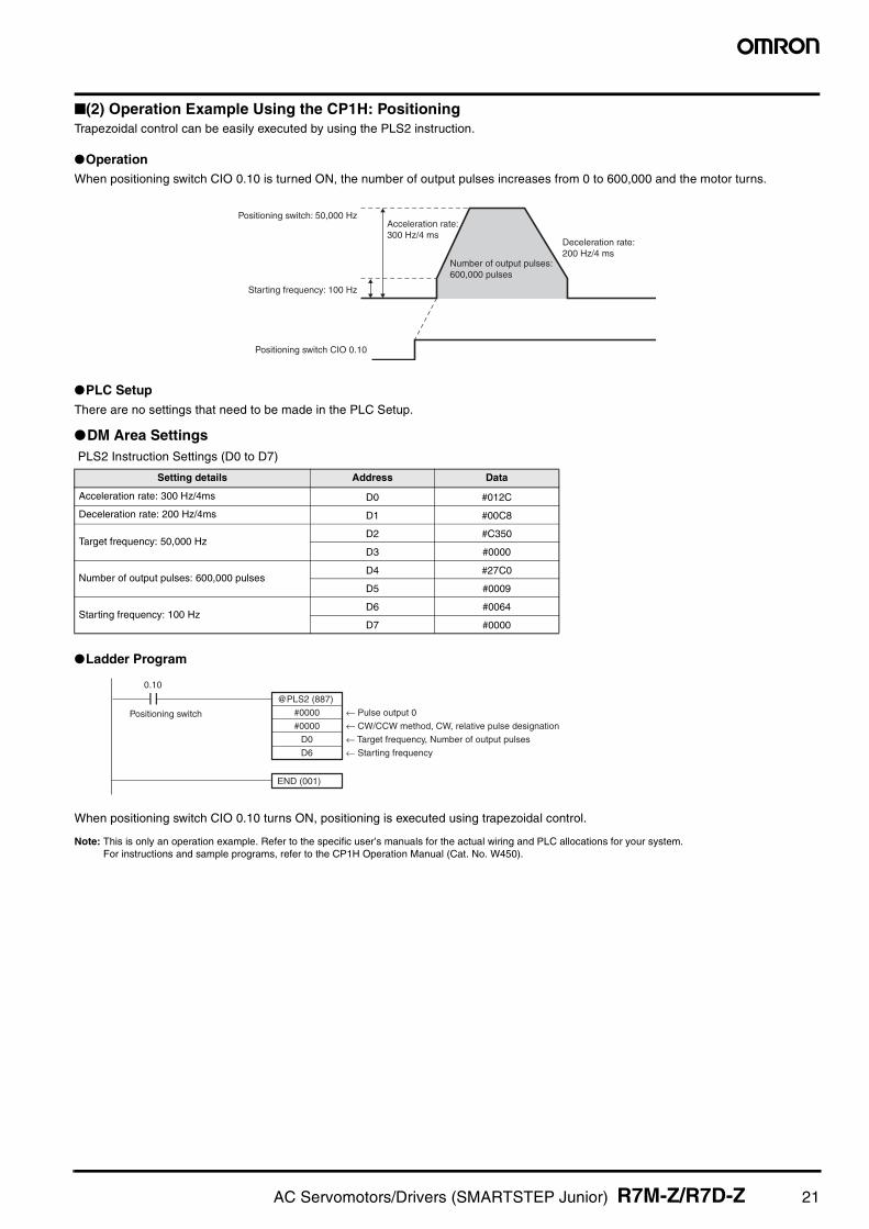
(2) Operation Example Using the CP1H: PositioningTrapezoidal control can be easily executed by using the PLS2 instruction.
OperationWhen positioning switch CIO 0.10 is turned ON, the number of output pulses increases from 0 to 600,000 and the motor turns.
PLC SetupThere are no settings that need to be made in the PLC Setup.
DM Area Settings PLS2 Instruction Settings (D0 to D7)
Ladder Program
When positioning switch CIO 0.10 turns ON, positioning is executed using trapezoidal control.
Note: This is only an operation example. Refer to the specific user’s manuals for the actual wiring and PLC allocations for your system. For instructions and sample programs, refer to the CP1H Operation Manual (Cat. No. W450).
Setting details Address Data
Acceleration rate: 300 Hz/4ms D0 #012C
Deceleration rate: 200 Hz/4ms D1 #00C8
Target frequency: 50,000 HzD2 #C350
D3 #0000
Number of output pulses: 600,000 pulsesD4 #27C0
D5 #0009
Starting frequency: 100 HzD6 #0064
D7 #0000
Positioning switch: 50,000 Hz
Starting frequency: 100 Hz
Positioning switch CIO 0.10
Acceleration rate: 300 Hz/4 ms
Deceleration rate: 200 Hz/4 ms
Number of output pulses: 600,000 pulses
← Pulse output 0
← CW/CCW method, CW, relative pulse designation
← Target frequency, Number of output pulses
← Starting frequency
#0000
@PLS2 (887)
#0000
D0
D6
END (001)
0.10
Positioning switch
AC Servomotors/Drivers (SMARTSTEP Junior) R7M-Z/R7D-Z 21

Standard Wiring
24 VDC
L1
L2
+
− SMARTSTEP Junior Servo Driver
SMARTSTEP Junior Servomotor
W
V
U
B
E
M
CN2
Servomotor power cable
24 VDC
XB
External Regeneration Unit
Encoder cable
P
C1 C2
OFF
X
ON
Main-circuit power supply
1MC
Main-circuit contactor
1MC
PL
Surge killer
Servo error indication
R T
NFB
Noise filter
1 2
3 4
E NF
Class D ground Class 3 ground
(to 100 Ω or less)
Single phase 200 to 230 V AC, 50/60 Hz: R7D-ZP@
AC reactor
Fuse
1MC
Shell
FG Frame ground
RUN
+24VIN
24 VCC RUN command 6
5
9
8
4
3
2
1 150 Ω
150 Ω
150 Ω
Reverse pulse
Forward pulse
Deviation counter reset
3.4 k
−ECRST
+ECRST
−CCW
+CCW
−CW
+CW
Position commands
The shield is connected to the connector shell.
Phase-Z output
Brake interlock
Positioning completed output
Alarm output
7
14
13
12
10
11
BKIR
ALM
Z
ZCOM
INP
0GND
X
XB
N
RG
JP
CN1Must be grounded.
Note: Be sure to install fuses (such as Littel fuses) for protection. For details, refer to the SMARTSTEP Junior User's Manual (Cat. No. I553).
Class D ground Class 3 ground (to 100 Ω or less)
22 AC Servomotors/Drivers (SMARTSTEP Junior) R7M-Z/R7D-Z

Connecting Cables
Main Circuit Connector (for CNA)
Power Cables (for CNB)
Encoder Cables (For CN2)
Note: The maximum cable length that can be used between the Servo Driver and Servomotor is 20 m. Cable over 10 m must be prepared by the user.
Symbol Name Connects to Model Description
(1) Main Circuit Connector R7D-ZP Connector R7A-CNZ01P
Symbol Name Connects to Model Description
(2)
Power Cable without brake line
Motor without BrakeR7M-Z@@@30-S1
R7A-CAZ@@@SThe boxes in the model number are for the cable length: 3 m, 5 m or 10 m (See note.)
Power Cable with brake line
Motor with BrakeR7M-Z@@@30-BS1
R7A-CAZ@@@BThe boxes in the model number are for the cable length: 3 m, 5 m or 10 m (See note.)
Symbol Name Connects to Model Description
(3) Encoder Cable R7M-Z@@@30-@S1
R7A-CRZ@@@CThe boxes in the model number are for the cable length:3 m, 5 m or 10 m (See note.)
(8)
(7)
(1)
(5) (6)
A
12
34
N
1
2
3
4
(2)
(3)
SMARTSTEP Servomotor (8) Connector Terminal Block
(4) Servo Relay Unit
SMARTSTEPServo Driver
Position Control Unit
Position Control Unit (with pulse output)
A
12
34
N
Model: 04JFAT-SBXGF-N (JST Mfg. Co. Ltd.)
Motor Connector (Molex)Connector Plug: 5557-06R-210Connector Case: 5556TL
Driver Connector (JST Mfg. Co. Ltd.)Connector Plug: 04JFAT-SAYGF-N
Motor Connector (Molex)Connector Plug: 5557-06R-210Connector Case: 5556TL
Driver Connector (JST Mfg. Co. Ltd.)Connector Plug: 04JFAT-SAYGF-N
Motor Connector (Molex)Connector Plug: 5557-12R-210Connector Case: 5556T2L
Driver Connector (Sumitomo 3M)Connector Plug: 36210-0100FDConnector Case: 36310-3200-008
AC Servomotors/Drivers (SMARTSTEP Junior) R7M-Z/R7D-Z 23

Control Cables (For CN1)
Symbol Name Connects to Model
(4) Servo Relay Unit
Position Control Units(CS1W-NC113/133, CJ1W-NC113/133, C200HW-NC113)
XW2B-20J6-1B
Position Control Units (CS1W-NC213/233/413/433, CJ1W-NC213/233/413/433, C200HW-NC213/413)
XW2B-40J6-2B
FQM1 Series (FQM1-MMP22)Customizable Counter Unit (CS1W-HCP22-V1)
XW2B-80J7-1A
One-axis Servo Relay Unit for CJ1M-CPU21/22/23 CPU Unit XW2B-20J6-8A
Two-axis Servo Relay Unit for CJ1M-CPU21/22/23 CPU Unit XW2B-40J6-9A
(5) Cable to Servo Driver
XW2B-@@J6-@B (Position Control Unit)XW2Z-@@@J-B17 The boxes in the model number are for the cable length: 1 m or 2 m.
XW2B-20J6-8A/-40J6-9A (CJ1M-CPU)XW2Z-@@@J-B17 The boxes in the model number are for the cable length: 1 m or 2 m.
XW2B-80J7-1A (FQM1)XW2Z-@@@J-B20 The boxes in the model number are for the cable length: 1 m or 2 m.
XW2B-80J7-1A (Customizable Counter Unit)XW2Z-@@@J-B18 The boxes in the model number are for the cable length: 1 m or 2 m.
(6)Cable to Position Control Unit
CS1W-NC113 and C200HW-NC113XW2Z-@@@J-A8 The boxes in the model number are for the cable length: 0.5 m or 1 m
CS1W-NC213/413 and C200HW-NC213/413XW2Z-@@@J-A9 The boxes in the model number are for the cable length: 0.5 m or 1 m
CS1W-NC133XW2Z-@@@J-A12 The boxes in the model number are for the cable length: 0.5 m or 1 m
CS1W-NC233/433XW2Z-@@@J-A13 The boxes in the model number are for the cable length: 0.5 m or 1 m
CJ1W-NC113XW2Z-@@@J-A16 The boxes in the model number are for the cable length: 0.5 m or 1 m
CJ1W-NC213/413XW2Z-@@@J-A17 The boxes in the model number are for the cable length: 0.5 m or 1 m
CJ1W-NC133XW2Z-@@@J-A20 The boxes in the model number are for the cable length: 0.5 m or 1 m
CJ1W-NC233/433XW2Z-@@@J-A21 The boxes in the model number are for the cable length: 0.5 m or 1 m
FQM1-MMP22
General-purpose I/O Cables
XW2Z-@@@J-A28 The boxes in the model number are for the cable length: 0.5 m or 1 m
Special I/O CablesXW2Z-@@@J-A30 The boxes in the model number are for the cable length: 0.5 m or 1 m
CS1W-HCP22-V1
General-purpose I/O Cables
XW2Z@@@J-A29 The boxes in the model number are for the cable length: 0.5 m or 1 m
Special I/O CablesXW2Z-@@@J-A32 The boxes in the model number are for the cable length: 0.5 m or 1 m
CJ1M-CPU21/22/23 for 2 axes XW2Z-100J-A26 Cable length: 1 m
(7) Control Cable For general-purpose ControllersR7A-CPZ@@@S The boxes in the model number are for the cable length: 1 m or 2 m.
(8)
Connector-Terminal Block Cable
For general-purpose Controllers
XW2Z-@@@J-B19 The boxes in the model number are for the cable length: 1 m or 2 m.
Connector-Terminal Block Conversion Unit
XW2B-20G5
24 AC Servomotors/Drivers (SMARTSTEP Junior) R7M-Z/R7D-Z

Model Number LegendsAC Servomotors
R7M-Z@@@@@-@@@(1) (2) (3) (4) (5) (6)
AC Servo Drivers
R7D-ZP@@@(1) (2) (3) (4)
Servomotor and Servo Driver Combinations
No. Item Code Specification
(1) Indicates a Servomotor
(2) Series Z SMARTSTEP Junior
(3) Motor capacity
100 100 W
200 200 W
400 400 W
750 750 W
(4) Speed 30 3000 r/min
(5) BrakeBlank No brake
B 24-V DC brake
(6) Shaft S1 Straight shaft with key
No. Item Code Specification
(1) Indicates a Servo Driver
(2)
Series Z SMARTSTEP Junior
Input signal designation
P Pulse train input
(3)Maximum output capacity
01 100 W
02 200 W
04 400 W
08 750 W
(4)Power supply specification
H 200 VAC
Rated output
Servomotor Servo Driver
Without brake With Brake Pulse train input
100 W R7M-Z10030-S1 R7M-Z10030-BS1 R7D-ZP01H
200 W R7M-Z20030-S1 R7M-Z20030-BS1 R7D-ZP02H
400 W R7M-Z40030-S1 R7M-Z40030-BS1 R7D-ZP04H
750 W R7M-Z75030-S1 R7M-Z75030-BS1 R7D-ZP08H
AC Servomotors/Drivers (SMARTSTEP Junior) R7M-Z/R7D-Z 25

Ordering GuideAC Servomotors
Cylindrical Servomotors (3000-r/min)
AC Servo Drivers
Note: The Main Circuit Connector is not included and must be obtained separately.
Main Circuit Connector
Reduction Gear (Straight Shaft with Key)
Cylindrical Servomotor (Backlash within 45 Minutes)
Cylindrical Servomotor (Backlash within 3 Minutes)
Control Cables for CN1
Note: For details on “Servo Relay Units” and “Connecting Cable”, refer to pages23 and 24.
Power Cables
Encoder Cables
Connectors
External Regeneration Unit
External Regeneration Resistor
AC Reactor
Specifications Model
Straight shaft with key
Without brake
100 W R7M-Z10030-S1
200 W R7M-Z20030-S1
400 W R7M-Z40030-S1
750 W R7M-Z75030-S1
With brake
100 W R7M-Z10030-BS1
200 W R7M-Z20030-BS1
400 W R7M-Z40030-BS1
750 W R7M-Z75030-BS1
Specifications Model
200 V AC
100 W R7D-ZP01H
200 W R7D-ZP02H
400 W R7D-ZP04H
750 W R7D-ZP08H
Specification Model
Main Circuit Connector (for CNA) R7A-CNZ01P
Motor capacity
ModelDeceleration
(deceleration ratio)
1/5 1/9 1/15
100 W
R7G-RGSF05B100
R7G-RGSF09B100
R7G-RGSF15B100
200 W
R7G-RGSF05B200
R7G-RGSF09C400
R7G-RGSF15C400
400 W
R7G-RGSF05C400
R7G-RGSF09C400
R7G-RGSF15C400
Motor capacity
ModelDeceleration
(deceleration ratio)
1/5 1/9 1/15 1/25
100 W
R7G-VRSFPB05B100
R7G-VRSFPB09B100
R7G-VRSFPB15B100
R7G-VRSFPB25C100
200 W
R7G-VRSFPB05B200
R7G-VRSFPB09C400
R7G-VRSFPB15C400
R7G-VRSFPB25C200
400 W
R7G-VRSFPB05C400
R7G-VRSFPB09C400
R7G-VRSFPB15C400
R7G-VRSFPB25D400
750 W
R7G-VRSFPB05C750
R7G-VRSFPB09D750
R7G-VRSFPB15D750
R7G-VRSFPB25E750
Specifications Model
Control Cable for General-purpose Controllers
1 m R7A-CPZ001S
2 m R7A-CPZ002S
For General-purpose Controllers
Cable for Connector terminal blocks
1 m XW2Z-100J-B19
2 m XW2Z-200J-B19
Connector-Terminal Block Conversion Unit
XW2B-20G5
Specifications Model
Power Cables
For Motors without brakes
3 m R7A-CAZ003S
5 m R7A-CAZ005S
10 m R7A-CAZ010S
For Motors with brakes
3 m R7A-CAZ003B
5 m R7A-CAZ005B
10 m R7A-CAZ010B
Specifications Model
Encoder Cables
3 m R7A-CRZ003C
5 m R7A-CRZ005C
10m R7A-CRZ010C
Specifications Model
Control I/O Connector R7A-CNA01R
Motor Connector (CNB) R7A-CNZ01A
Encoder Input Connector (CN2) R7A-CNZ01R
Encoder Connector (Motor side) R7A-CNZ02R
Servomotor Connector for Servomotor Power Cable
R7A-CNZ02A
Specifications Model
Regeneration current: 8 ABuilt-in resistance: 50 Ω, 12 W
R88A-RG08UA
Specifications Model
Regeneration capacity: 70 W, 47 Ω R88A-RR22047S
Specifications Model
For the R7D-ZP01H R88A-PX5052
For the R7D-ZP02H R88A-PX5053
For the R7D-ZP04H R88A-PX5054
For the R7D-ZP08H R88A-PX5056
26 AC Servomotors/Drivers (SMARTSTEP Junior) R7M-Z/R7D-Z

Read and Understand this Catalog
Please read and understand this catalog before purchasing the product. Please consult your OMRON representative if you have any questions or comments.
Warranty and Limitations of Liability
WARRANTY
OMRON's exclusive warranty is that the products are free from defects in materials and workmanship for a period of one year (or other period if specified) from date of sale by OMRON.
OMRON MAKES NO WARRANTY OR REPRESENTATION, EXPRESS OR IMPLIED, REGARDING NON-INFRINGEMENT, MERCHANTABILITY, OR FITNESS FOR PARTICULAR PURPOSE OF THE PRODUCTS. ANY BUYER OR USER ACKNOWLEDGES THAT THE BUYER OR USER ALONE HAS DETERMINED THAT THE PRODUCTS WILL SUITABLY MEET THE REQUIREMENTS OF THEIR INTENDED USE. OMRON DISCLAIMS ALL OTHER WARRANTIES, EXPRESS OR IMPLIED.
LIMITATIONS OF LIABILITY
OMRON SHALL NOT BE RESPONSIBLE FOR SPECIAL, INDIRECT, OR CONSEQUENTIAL DAMAGES, LOSS OF PROFITS, OR COMMERCIAL LOSS IN ANY WAY CONNECTED WITH THE PRODUCTS, WHETHER SUCH CLAIM IS BASED ON CONTRACT, WARRANTY, NEGLIGENCE, OR STRICT LIABILITY.
In no event shall the responsibility of OMRON for any act exceed the individual price of the product on which liability is asserted.
IN NO EVENT SHALL OMRON BE RESPONSIBLE FOR WARRANTY, REPAIR, OR OTHER CLAIMS REGARDING THE PRODUCTS UNLESS OMRON'S ANALYSIS CONFIRMS THAT THE PRODUCTS WERE PROPERLY HANDLED, STORED, INSTALLED, AND MAINTAINED AND NOT SUBJECT TO CONTAMINATION, ABUSE, MISUSE, OR INAPPROPRIATE MODIFICATION OR REPAIR.
Application Considerations
SUITABILITY FOR USE
OMRON shall not be responsible for conformity with any standards, codes, or regulations that apply to the combination of products in the customer's application or use of the products.
Take all necessary steps to determine the suitability of the product for the systems, machines, and equipment with which it will be used.
Know and observe all prohibitions of use applicable to this product.
NEVER USE THE PRODUCTS FOR AN APPLICATION INVOLVING SERIOUS RISK TO LIFE OR PROPERTY WITHOUT ENSURING THAT THE SYSTEM AS A WHOLE HAS BEEN DESIGNED TO ADDRESS THE RISKS, AND THAT THE OMRON PRODUCTS ARE PROPERLY RATED AND INSTALLED FOR THE INTENDED USE WITHIN THE OVERALL EQUIPMENT OR SYSTEM.
PROGRAMMABLE PRODUCTS
OMRON shall not be responsible for the user’s programming of a programmable product, or any consequence thereof.
Disclaimers
CHANGE IN SPECIFICATIONS
Product specifications and accessories may be changed at any time based on improvements and other reasons.
It is our practice to change model numbers when published ratings or features are changed, or when significant construction changes are made. However, some specifications of the products may be changed without any notice. When in doubt, special model numbers may be assigned to fix or establish key specifications for your application on your request. Please consult with your OMRON representative at any time to confirm actual specifications of purchased products.
DIMENSIONS AND WEIGHTS
Dimensions and weights are nominal and are not to be used for manufacturing purposes, even when tolerances are shown.
PERFORMANCE DATA
Performance data given in this catalog is provided as a guide for the user in determining suitability and does not constitute a warranty. It may represent the result of OMRON’s test conditions, and the users must correlate it to actual application requirements. Actual performance is subject to the OMRON Warranty and Limitations of Liability.
AC Servomotors/Drivers (SMARTSTEP Junior) R7M-Z/R7D-Z 27

Actual Size
New from OMRON: A Compact, Smart, New-generation Servo!
Authorized Distributor:
Note: Specifications subject to change without notice. Cat. No. I812-E1-01A
0107
Note: Do not use this document to operate the Unit.
OMRON CorporationIndustrial Automation Company
Control Devices Division H.Q.
Shiokoji Horikawa, Shimogyo-ku,Kyoto, 600-8530 JapanTel: (81)75-344-7109Fax: (81)75-344-7149
Regional Headquarters
OMRON EUROPE B.V.
Wegalaan 67-69, NL-2132 JD HoofddorpThe NetherlandsTel: (31)2356-81-300Fax: (31)2356-81-388
OMRON ELECTRONICS LLC
1 East Commerce Drive, Schaumburg, IL 60173 U.S.A.Tel: (1)847-843-7900/Fax: (1)847-843-8568
OMRON ASIA PACIFIC PTE. LTD.
83 Clemenceau Avenue, #11-01, UE Square,Singapore 239920Tel: (65)6835-3011/Fax: (65)6835-2711
OMRON (CHINA) CO., LTD.
Room 2211, Bank of China Tower, 200 Yin Cheng Zhong Road,PuDong New Area, Shanghai, 200120 ChinaTel: (86)21-5037-2222/Fax: (86)21-5037-2200
Printed on 100% Recycled Paper
R7D-ZP H
R7M-Z -S1/BS1
Top Related