


Languages
Pages
Legal

NATIONAL RADIO ASTRONOMY OBSERVATORY
Charlottesville, Virginia
Engineering Division Internal Report No. 110
The Design of the Deformable Subreflector
for the 140 ft. Radio Telescope
W-Y. Wong
January, 1979
Number of copies: 100
The Design of a Deformable Subreflector for
the 140-ft. Radio Telescope
W-Y. Wong
TABLE OF CONTENTS
Page
I. SUMMARY.. . . . • • • • ............................ ...........1
II. THE SUBREFLECTOR . . . .. • • •
•
2
General Description . . . • • • • • •
•
2
Geometry. . . . . . . . . . . . . . . . . 3
Material .................................... • • • • • . • • • • . ............ 5
Stress Analyses ........................ . . . ............................. . 6
Error Budget ................ ...................................................................7
Deforming the Subreflector Surface . . 0 • 9
The Motion of the Ideal Actuators. • • . 0 • • . . . 10
Evaluations and Measurements of the SubreflectorSurface. . • • • • . 11
Evaluationd and Measurements of the ExperimentalActuators. . . . 12
The Motion of the Experimental Actuators .................... 13
III. DEFORMING SYSTEM . • 0 • . . . • • . 15
General Description. . . 15
Electronic Control . . . . 15
Force Requirements on Actuators ........................................ 17
Type of Experimental Actuators . . 18
The Linkage ................................................................................ 19
The Switching Off of the Actuator .................................... 19
TABLE OF CONTENTS
(Continued)
Page
IV. BACK UP FRAME. . • • • • • • . . 20
General Description. . . • • • • • • • . 20
The Design . . . 20
V. SOFTWARE PROGRAMMING . . • • • • . . 22
General Description. • • • • • 0 • • • •
The Input and the Output . . • • • •
VI. MEASURING JIG. . O O O O O O O O O O O •
ACKNOWLEDGEMENT. . • • • • •
REFERENCE. . . ......... . • • •
LIST OF TABLE. . • • • • • • •
• 0 0 • •
• • • .
• • .
• 6 • a
22
. 22
. 24
. 25
. 26
. 28
FIGURE CAPTIONS .. • • . • • . 33
APPENDIX
A. Engineering Drawings of the SubreflectorSurface . • 0 • . . 40
B. Engineering Drawings of the Back up Frame. . . 48
C. Engineering Drawings of the Deforming System . . 58
D. Engineering Drawings of the Measuring Jig. . . . 63
E. Best Fit of a Hyperboloid ..................................................... 70
1
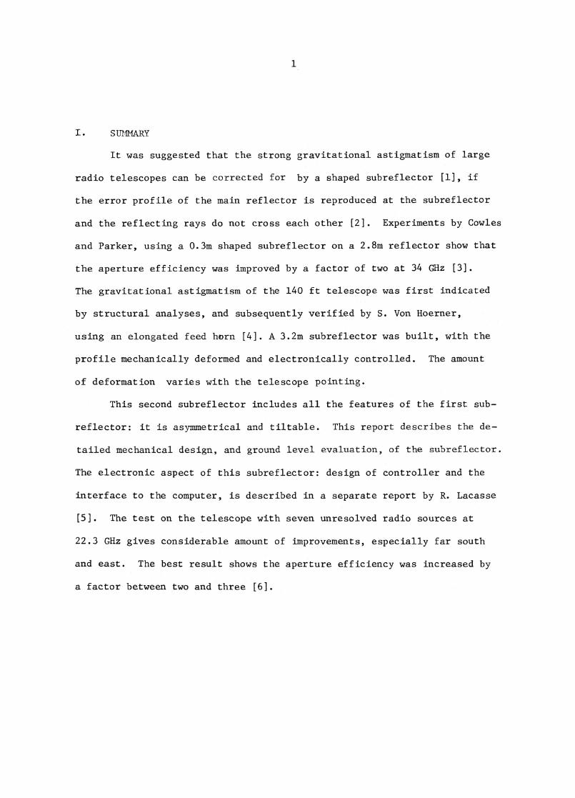
SUMMARY
It was suggested that the strong gravitational astigmatism of large
radio telescopes can be corrected for by a shaped subreflector [1], if
the error profile of the main reflector is reproduced at the subreflector
and the reflecting rays do not cross each other [2]. Experiments by Cowles
and Parker, using a 0.3m shaped subreflector on a 2.8m reflector show that
the aperture efficiency was improved by a factor of two at 34 GHz [3].
The gravitational astigmatism of the 140 ft telescope was first indicated
by structural analyses, and subsequently verified by S. Von Hoerner,
using an elongated feed horn [4]. A 3.2m subreflector was built, with the
profile mechanically deformed and electronically controlled. The amount
of deformation varies with the telescope pointing.
This second subreflector includes all the features of the first sub-
reflector: it is asymmetrical and tiltable. This report describes the de-
tailed mechanical design, and ground level evaluation, of the subreflector.
The electronic aspect of this subreflector: design of controller and the
interface to the computer, is described in a separate report by R. Lacasse
[5]. The test on the telescope with seven unresolved radio sources at
22.3 GHz gives considerable amount of improvements, especially far south
and east. The best result shows the aperture efficiency was increased by
a factor between two and three [6].
2
11. THE SUBREFLECTOR
General Description
The deformable subreflector has to follow the criteria that 1) the
subreflector is asymmetrical due to the off-set feed arrangement; 2) the
subreflector is tiltable for beam switching technique in observation; and
3) the subreflector is deformable to correct the gravitational astigmatism.
The first consideration was entirely geometric, readily defined
when the first subreflector was implemented to the telescope system. The
second consideration means that the weight and the moment of inertia of
the new system has to be kept equal to, if not less than, the previous sys-
tem. For the load capacity of the sterling mount, nominally set to 2500
lbs., was already exceeded. The third consideration was new to the system.
Four servo controlled motor-actuators are installed at four points behind
the subreflector. The amount of actuation is determined by the elevation
position of the telescope.
The fiberglass, aluminum honeycomb core sandwich construction method
is proven acceptable, in terms of cost and surface accuracy, by the first
subreflector. The force required for the deformation of the surface,
solved analytically, was found reasonable. Hence the same material and
fabrication approach for the new surface was adopted. The long term be-
havior of this composite material is not entirely known, however. Aging,
temperature, environment and cyclic loading effects might degrade the sur-
face accuracy and reduce its usable life time. The surface of the first sub-
reflector has degraded from the original error of 0.25 mm rms to 0.43 mm rms
after four years.
The stiffening rib arrangement of these two gubreflectors are also
different. The first subreflector has a stiffening ring, whereas the second
3
one has two stiff diagonals. For both cases, however, the main structural
stiffness is derived from the back-up frame which serves as an interface
between the beam-tilt system and the subreflector surface.
Due to the off-set receiver arrangement, the deforming feature is
applicable only to the feed position of the K-band maser receiver (22.3 GHz,
X = 1.23 cm) plus three others, rotated by 90°. For other receiver positions,
the subreflector's profile must be returned to its undeformed position.
The subreflector system can be dismounted from the telescope so that
the optic of the system can be modified within a reasonably short period
of time.
The front face of the subreflector is coated with a thin layer of
aluminum film for reflection. The subreflector is painted white. The
back-up frame is unpainted. All moving parts of the deforming system are
protected by water-tight covers.
Geometry
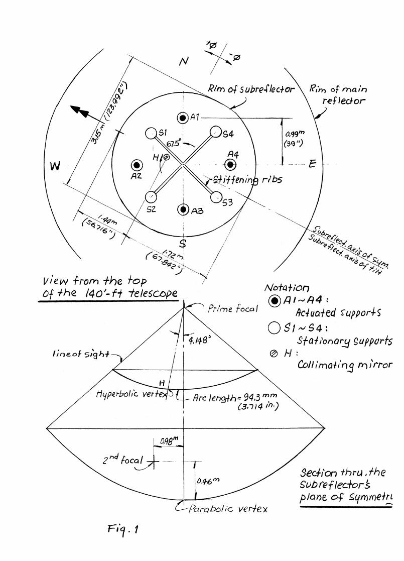
A schematic arrangement of the Cassegrain system for the 140-f
telescope is shown in Figure 1. Some important parameters are given in
the following list, describing the Cassegrain optics:
Average subreflector diameter = 3.213m (126.4")
Distance from the prime focus to secondary focus: a = 13.48m
(530.89")
Distance from the prime focus to subreflector vertex:
b = 1.30 (51.262")
Magnification: in = 9.348
Eccentricity: e = 1.240
Angle between paraboloic axis and hyperbolic axis: 4.148°
= (1)
4
The hyperboloid is given in eq. (1), describing the profile of the
subreflector in an untilted system, with Z-axis as the hyperbolic axis.
where r2 = x
2 + y
2 and c = a-b.
The hyperbolic axis and the parabolic axis do not coincide. They
subtend an angle of 4.148°. A cluster of feeds are arranged in a ring
with a radius of 0.98m (38.58") and they are 4.57m (180") above the ver-
tex [7]. The subreflectors' axis is aligned with the phase center of the
feed in use by rotating the subreflector about the axis of the main re-
flector at the Sterling mount. The rim of the subreflector, which is
the intersection of the hyperboloid and the cone defined by the line of
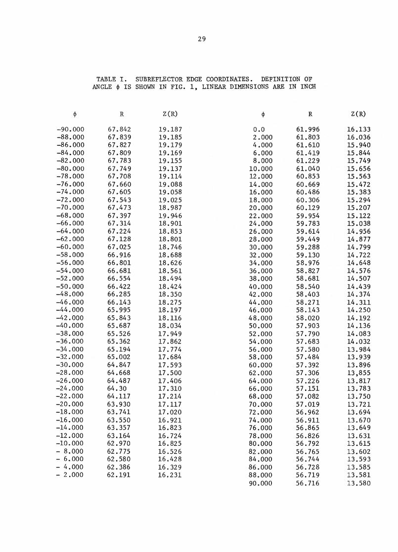
sight of the prime system, is not a circle. The coordinates of the rim
were computed by P. J. Napier and are listed in Table I for reference.
The rim is marked at every 15° with respect to the hyperbolic
axis. A collimating mirror with cross-hair defines the hyperbolic axis.
Another cross is marked 94.3 mm (1.714 in) from the hyperbolic axis along
the plane of symmetry which defines the parabolic axis of the subreflector.
The arrangement of the actuators (Al - A4) and the stationary con-
nections (51-54) are also illustrated in Figure 1, showing their positions
relative to the main reflector. The direction of the beam tilting is perpen-
dicular to the parabolic and hyperbolic axes. The relative position of
the subreflector to the main reflector is defined when a particular receiver
is used. For example, the actuator Al is aligned to the northern rim of
the main reflector only when the K-band maser receiver is in use.
5
Material
The subreflector shell structure is composed of fiberglass cloths,
and an aluminum honeycomb core. This sandwich construction is bonded
together by epoxy rasin cured by hardener, or curing agent. There are
three plies of fiberglass cloth laminates on the front and the back of
the shell. The thickness of each ply is 0.28mm (0.011 'n). The honeycomb
core is 25.4mm (1.0 in) thick.
The shell structure is laid out in steps in a mold and bonded
together with the epoxy. The curing takes place inside the mold.
Suction was constantly applied between the mold and the front surface to
insure the reproduction of the profile in the mold. The curing agent was
selected so that room temperature curing is adequate to achieve the neces-
sary material strength. Shrinkage of the curing agent is claimed to be
less than 27.
A thin layer (about 0.15mm) of aluminum film was flame-sprayed
onto the mold before the epoxy-fiberglass was applied to make the surface
reflective.
The quality of this composite construction depends on the material
properties of the components as well as on the skill of the fabrication,
the type of curing agent and the duration of the curing. Temperature,
pressure and types of fiberglass cloth also affect the strength of the
product. Moreover, there is a wide selection of size, foil thickness and
alloy of the aluminum honeycomb core. Because of the many possible combina-
tions, the material properties of the final product is best determined by
direct measurements. On the other hand, tests on specimens are usually
6
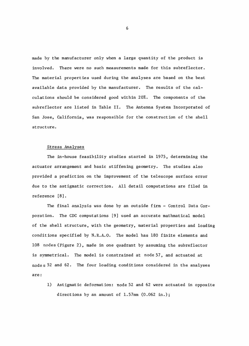
made by the manufacturer only when a large quantity of the product is
involved. There were no such measurements made for this subreflector.
The material properties used during the analyses are based on the best
available data provided by the manufacturer. The results of the cal-
culations should be considered good within 20%. The components of the
subreflector are listed in Table II. The Antenna System Incorporated of
San Jose, California, was responsible for the construction of the shell
structure.
Stress Analyses
The in-house feasibility studies started in 1975, determining the
actuator arrangement and basic stiffening geometry. The studies also
provided a prediction on the improvement of the telescope surface error
due to the astigmatic correction. All detail computations are filed in
reference [8].
The final analysis was done by an outside firm - Control Data Cor-
poration. The CDC computations [9] used an accurate mathmatical model
of the shell structure, with the geometry, material properties and loading
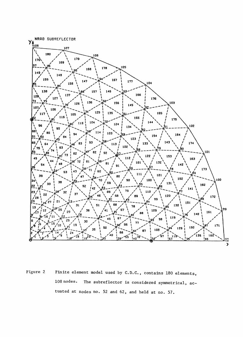
conditions specified by N.R.A.O. The model has 180 finite elements and
108 nodes (Figure 2), made in one quadrant by assuming the subreflector
is symmetrical. The model is constrained at node 57, and actuated at
nodes 52 and 62. The four loading conditions considered In the analyses
are:
1) Astigmatic deformation: node 52 and 62 were actuated in opposite
directions by an amount of 1.57mm. (0.062 in.);
7
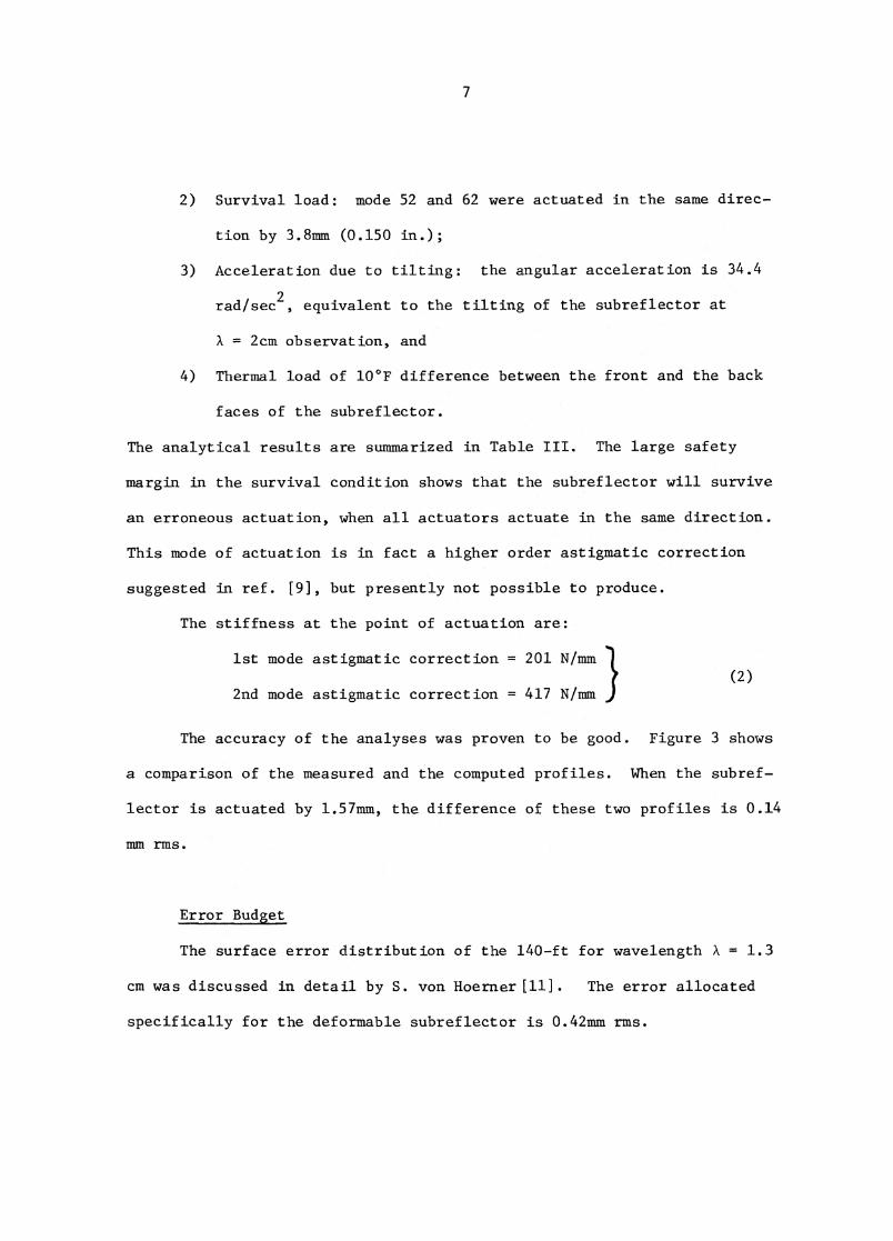
2) Survival load: mode 52 and 62 were actuated in the same direc-
tion by 3.8mm (0.150 in.);
3) Acceleration due to tilting: the angular acceleration is 34.4
rad/sec2, equivalent to the tilting of the subreflector at
= 2cm observation, and
4) Thermal load of 10°F difference between the front and the back
faces of the subreflector.
The analytical results are summarized in Table III. The large safety
margin in the survival condition shows that the subreflector will survive
an erroneous actuation, when all actuators actuate in the same direction.
This mode of actuation is in fact a higher order astigmatic correction
suggested in ref. [9], but presently not possible to produce.
The stiffness at the point of actuation are:
1st mode astigmatic correction = 201 N/mm(2)
2nd mode astigmatic correction = 417 N/mm 1
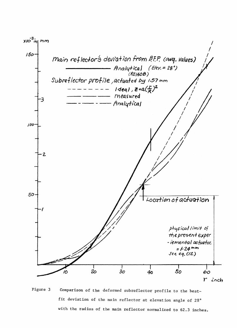
The accuracy of the analyses was proven to be good. Figure 3 shows
a comparison of the measured and the computed profiles. When the subref-
lector is actuated by 1.57mm, the difference of these two profiles is 0.14
mm rms.
Error Budget
The surface error distribution of the 140-ft for wavelength A = 1.3
cm was discussed in detail by S. von Hoerner[11]. The error allocated
specifically for the deformable subreflector is 0.42mm rms.
8
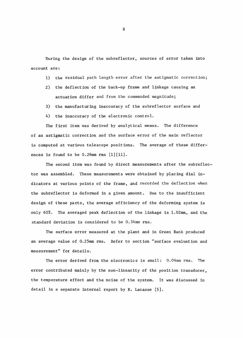
During the design of the subreflector, sources of error taken into
account are:
1) the residual path length error after the astigmatic correction;
2) the deflection of the back-up frame and linkage causing an
actuation differ and from the commanded magnitude;
3) the manufacturing inaccuracy of the subreflector surface and
4) the inaccuracy of the electronic control.
The first item was derived by analytical means. The difference
of an astigmatic correction and the surface error of the main reflector
is computed at various telescope positions. The average of these differ-
ences is found to be 0.26mm rms [1][11].
The second item was found by direct measurements after the subreflec-
tor was assembled. These measurements were obtained by placing dial in-
dicators at various points of the frame, and recorded the deflection when
the subreflector is deformed in a given amount. Due to the insufficient
design of these parts, the average efficiency of the deforming system is
only 60%. The averaged peak deflection of the linkage is 1.02mm, and the
standard deviation is considered to be 0.34mm rms.
The surface error measured at the plant and in Green Bank produced
an average value of 0.25mm rms. Refer to section "surface evaluation and
measurement" for details.
The error derived from the electronics is small: 0.04mm rms. The
error contributed mainly by the non-linearity of the position transducer,
the temperature effect and the noise of the system. It was discussed in
detail in a separate internal report by R. Lacasse [5].
9
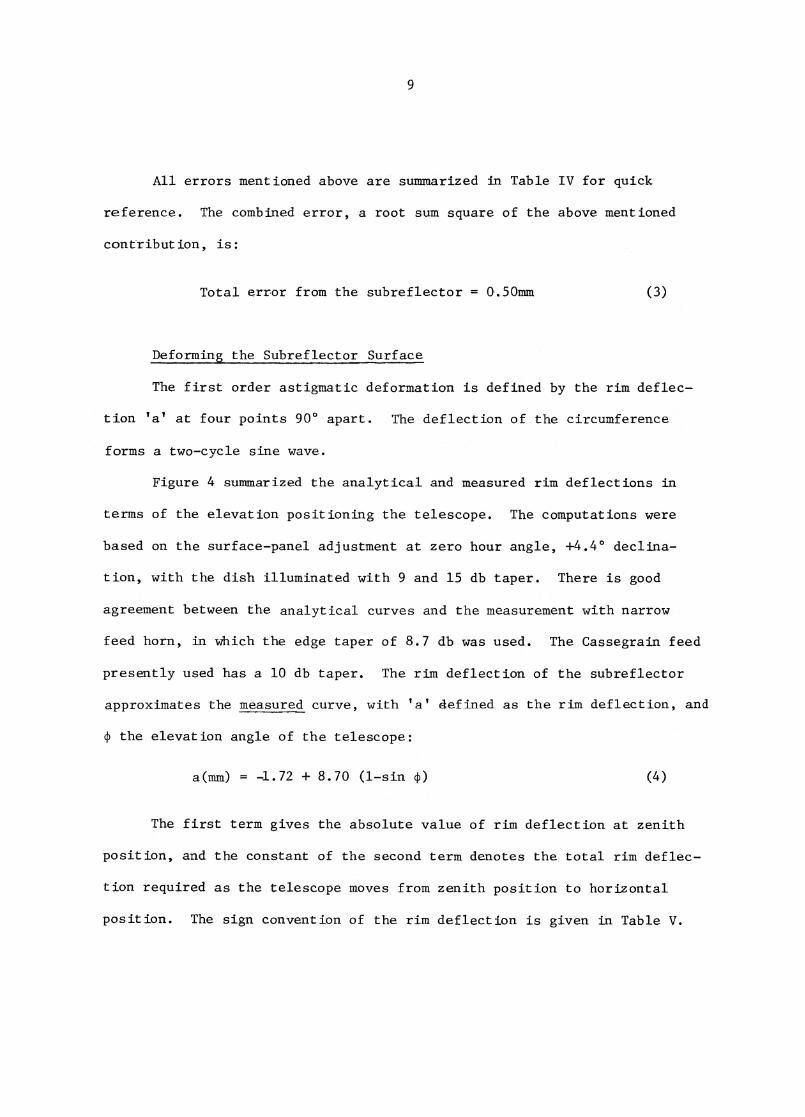
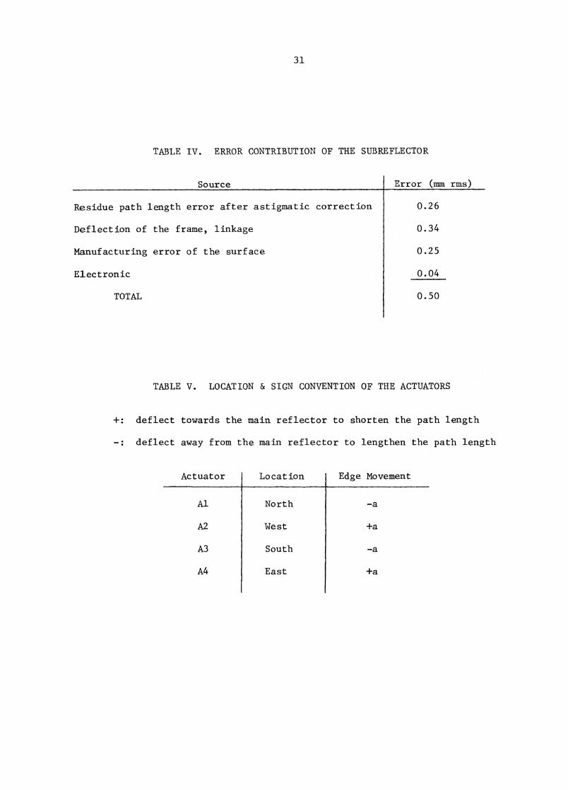
All errors mentioned above are summarized in Table IV for quick
reference. The combined error, a root sum square of the above mentioned
contribution, is:
Total error from the subreflector = 0.50mm (3)
Deforming the Subreflector Surface
The first order astigmatic deformation is defined by the rim deflec-
tion 'a' at four points 900 apart. The deflection of the circumference
forms a two-cycle sine wave.
Figure 4 summarized the analytical and measured rim deflections in
terms of the elevation positioning the telescope. The computations were
based on the surface-panel adjustment at zero hour angle, +4.4° declina-
tion, with the dish illuminated with 9 and 15 db taper. There is good
agreement between the analytical curves and the measurement with narrow
feed horn, in which the edge taper of 8.7 db was used. The Cassegrain feed
presently used has a 10 db taper. The rim deflection of the subreflector
approximates the measured curve, with 'a' defined as the rim deflection, and
(1) the elevation angle of the telescope:
a(mm) = -1.72 + 8.70 (1-sin 0 (4)
The first term gives the absolute value of rim deflection at zenith
position, and the constant of the second term denotes the total rim deflec-
tion required as the telescope moves from zenith position to horizontal
position. The sign convention of the rim deflection is given in Table V.
10
Positive denotes a deflection towards the main reflector; whereas negative
denotes a deflection away from the main reflector. Plus sign means a re-
duction of path length, and negative an addition to the path length.
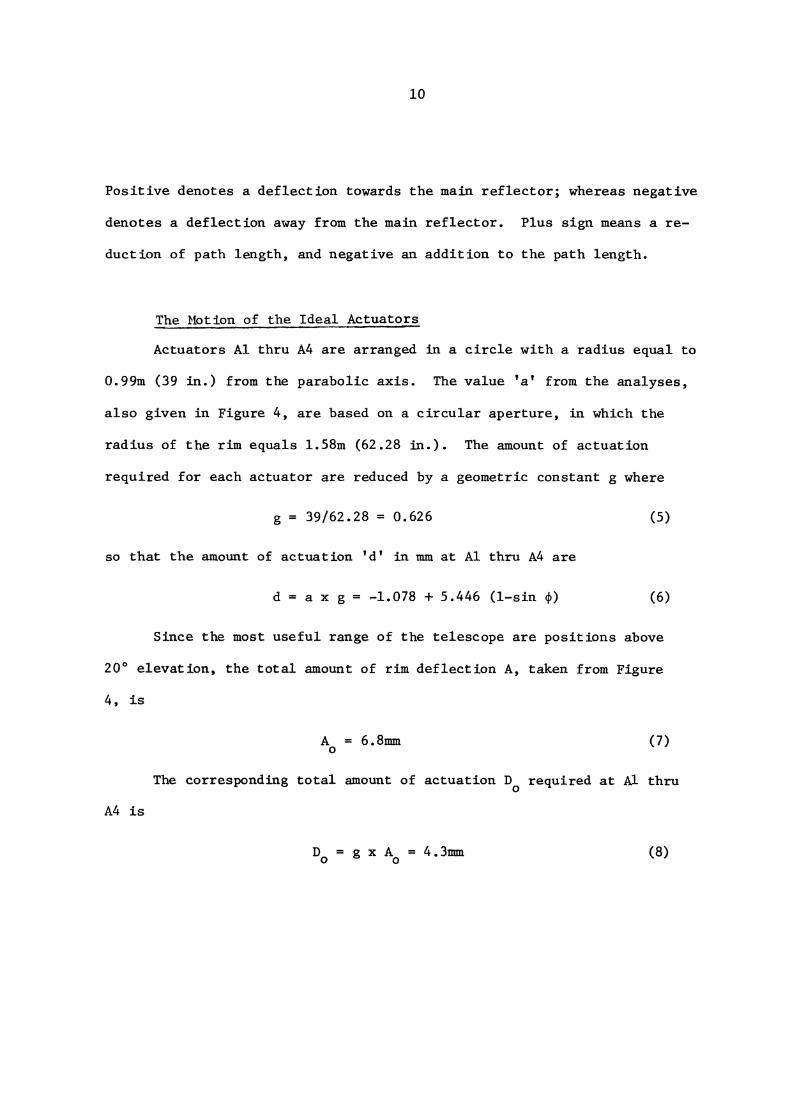
The Motion of the Ideal Actuators
Actuators Al thru ALF are arranged in a circle with a radius equal to
0.99m (39 in.) from the parabolic axis. The value 'a' from the analyses,
also given in Figure 4, are based on a circular aperture, in which the
radius of the rim equals 1.58m (62.28 in The amount of actuation
required for each actuator are reduced by a geometric constant g where
g = 39/62.28 = 0.626 (5)
so that the amount of actuation 'd' in mm at Al thru A4 are
d=axg= -1.078 + 5.446 (1-sin 0 (6)
Since the most useful range of the telescope are positions above
20° elevation, the total amount of rim deflection A, taken from Figure
4, is
Ao
= 6.8mm(7)
The corresponding total amount of actuation D o required at Al thru
A4 is
Do =gxA
o=4 .3mm (8)
11
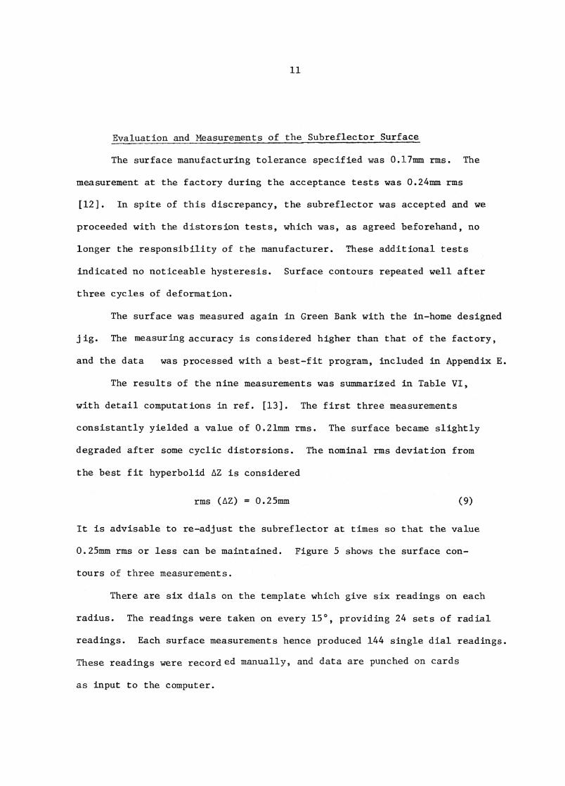
Evaluation and Measurements of the Subreflector Surface
The surface manufacturing tolerance specified was 0.17mm rms. The
measurement at the factory during the acceptance tests was 0.24mm rms
[12]. In spite of this discrepancy, the subreflector was accepted and we
proceeded with the distorsion tests, which was, as agreed beforehand, no
longer the responsibility of the manufacturer. These additional tests
indicated no noticeable hysteresis. Surface contours repeated well after
three cycles of deformation.
The surface was measured again in Green Bank with the in-home designed
jig. The measuring accuracy is considered higher than that of the factory,
and the data was processed with a best-fit program, included in Appendix E.
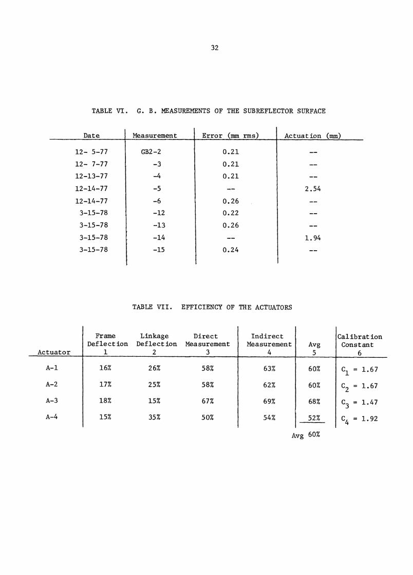
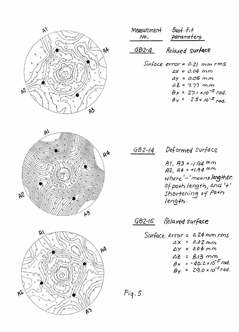
The results of the nine measurements was summarized in Table VI,
with detail computations in ref. [13]. The first three measurements
consistantly yielded a value of 0.21mm rms. The surface became slightly
degraded after some cyclic distorsions. The nominal rms deviation from
the best fit hyperbolid AZ is considered
rms (AZ) = 0.25mm (9)
It is advisable to re-adjust the subreflector at times so that the value
0.25mm rms or less can be maintained. Figure 5 shows the surface con-
tours of three measurements.
There are six dials on the template which give six readings on each
radius. The readings were taken on every 15°, providing 24 sets of radial
readings. Each surface measurements hence produced 144 single dial readings.
These readings were record ed manually, and data are punched on cards
as input to the computer.
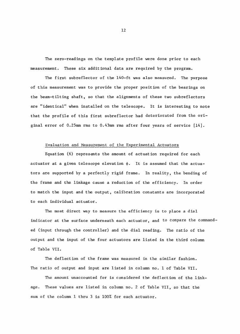
12
The zero-readings on the template profile were done prior to each
measurement. These six additional data are required by the program.
The first subreflector of the 140-ft was also measured. The purpose
of this measurement was to provide the proper position of the bearings on
the beam-tilting shaft, so that the alignments of these two subreflectors
are "identical" when installed on the telescope. It is interesting to note
that the profile of this first subreflector had deteriorated from the ori-
ginal error of 0.25mm rms to 0.43mm rms after four years of service [14].
Evaluation and Measurement of the Ex erimental Actuators
Equation (6) represents the amount of actuation required for each
actuator at a given telescope elevation (P. It is assumed that the actua-
tors are supported by a perfectly rigid frame. In reality, the bending of
the frame and the linkage cause a reduction of the efficiency. In order
to match the input and the output, calibration constants are incorporated
to each individual actuator.
The most direct way to measure the efficiency is to place a dial
indicator at the surface underneath each actuator, and to compare the command-
ed (input through the controller) and the dial reading. The ratio of the
output and the input of the four actuators are listed in the third column
of Table VII.
The deflection of the frame was measured in the similar fashion.
The ratio of output and input are listed in column no. 1 of Table VII.
The amount unaccounted for is considered the deflection of the link-
age. These values are listed in column no. 2 of Table VII, so that the
sum of the column 1 thru 3 is 100% for each actuator.
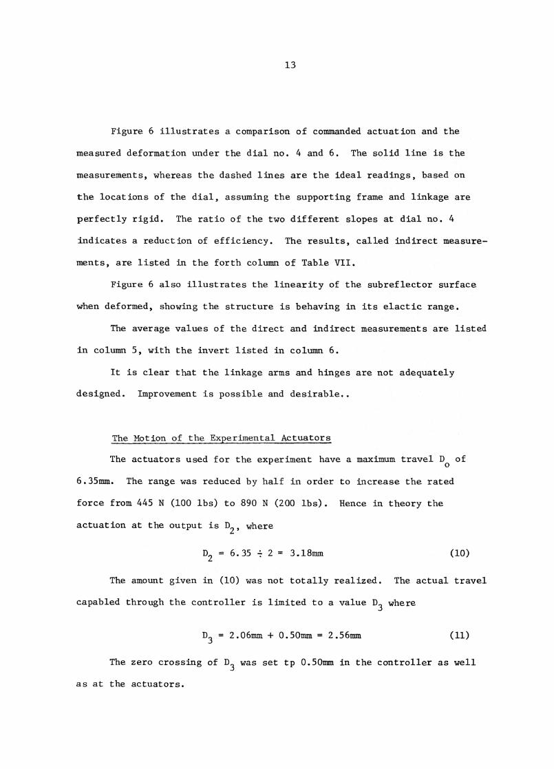
13
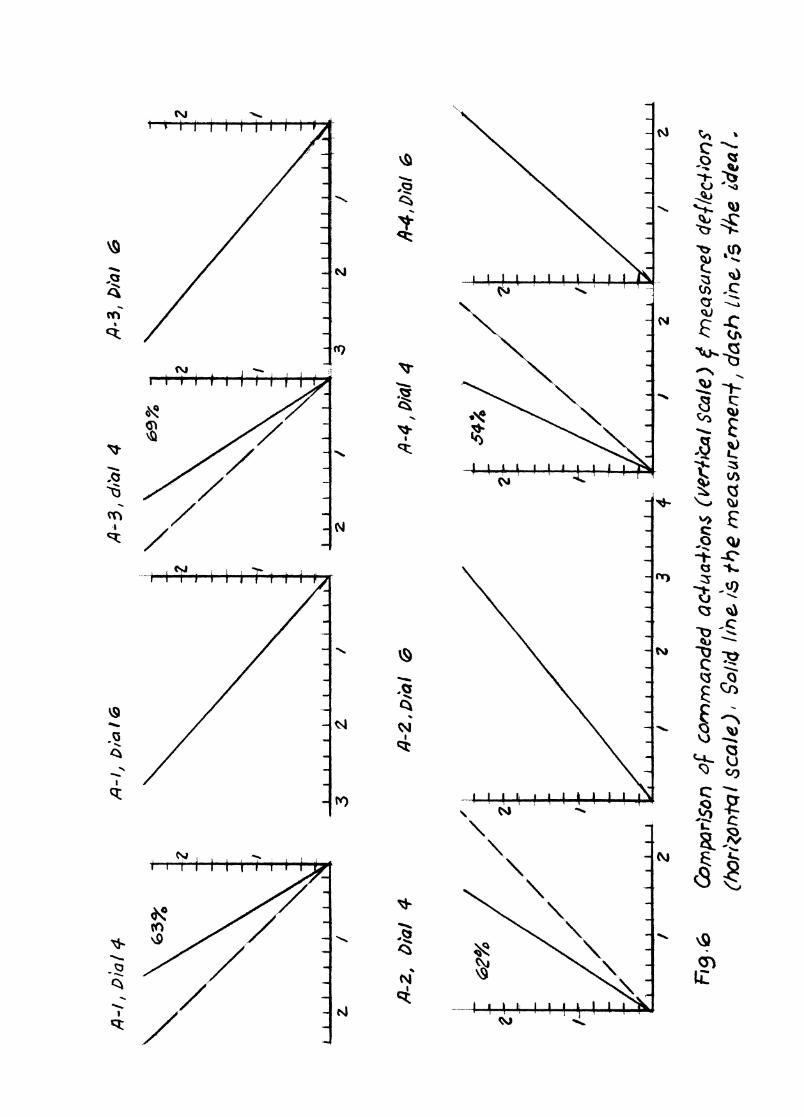
Figure 6 illustrates a comparison of commanded actuation and the
measured deformation under the dial no. 4 and 6. The solid line is the
measurements, whereas the dashed lines are the ideal readings, based on
the locations of the dial, assuming the supporting frame and linkage are
perfectly rigid. The ratio of the two different slopes at dial no. 4
Indicates a reduction of efficiency. The results, called indirect measure-
ments, are listed in the forth column of Table VII.
Figure 6 also illustrates the linearity of the subreflector surface
when deformed, showing the structure is behaving in its elactic range.
The average values of the direct and indirect measurements are listed
in column 5, with the invert listed in column 6.
It is clear that the linkage arms and hinges are not adequately
designed. Improvement is possible and desirable..
The Motion of the Experimental Actuators
The actuators used for the experiment have a maximum travel D o of
6.35mro.. The range was reduced by half in order to increase the rated
force from 445 N (100 lbs) to 890 N (200 lbs). Hence in theory the
actuation at the output is D2' where
D2 = 6.35 4 2 = 3.18mm•
The amount given in (10) was not totally realized. The actual travel
capabled through the controller is limited to a value D3 where
D3 = 2.06mm 4 . 0.50mm = 2.56mm
The zero crossing of D3
was set tp 0.50mm in the controller as well
as at the actuators.
(10)
14
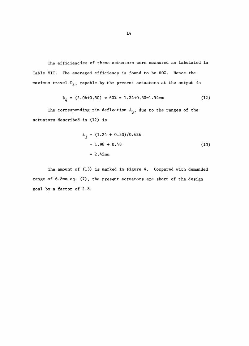
The efficiencies of these actuators were measured as tabulated in
Table VII. The averaged efficiency is found to be 60%. Hence the
maximum travel D
4' capable by the present actuators at the output is
D4 = (2.06+0.50) x 60% = 1.24+0.30=1.54mm (12)
The corresponding rim deflection A
3' due to the ranges of the
actuators described in (12) is
A3 = (1.24 + 0.30)/0.626
= 1.98 + 0.48 (13)
= 2.45mm
The amount of (13) is marked in Figure 4. Compared with demanded
range of 6.8mm eq. (7), the present actuators are short of the design
goal by a factor of 2.8.
15
III. DEFORMING SYSTEM
General Description
The deformation of the subreflector is controlled by four indepen-
dent and identical systems. Each system controls the contour of one quad-
rant of the surface. Each system has its own position control. The in-
fluence of deformation in one quadrant to the others is reduced because
of the two stiff diagonals on the back of the subreflector (Figure 1).
The deforming system has four major parts: an electronic control,
a position transducer, a motor actuator and a lever arm linkage. The first
three items are covered in the internal report 139 in detail by R. Lacasse
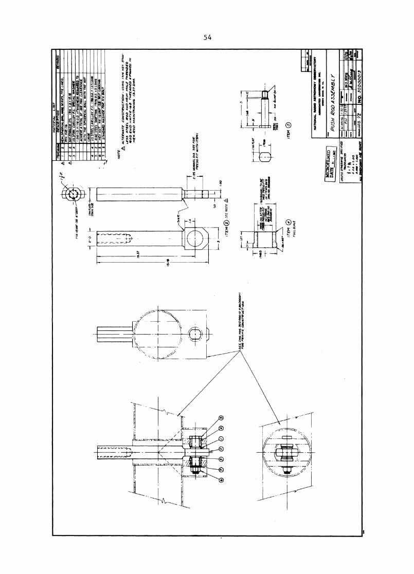
[5]. The lever arm linkage is illustrated in a detail drawing, no. 30D00017
in Appendix C.
This deforming system is an experimental version. Once this deform-
able subreflector is proven workable, the deforming system should be modi-
fied to incorporate actuators with a larger amount of actuations. A reverse
in the direction of actuation will make the subreflector more versitile:
it will be usable for receivers placed + 90 0 and 1800 apart from the present
K,band maser receiver location.
Electronic Control
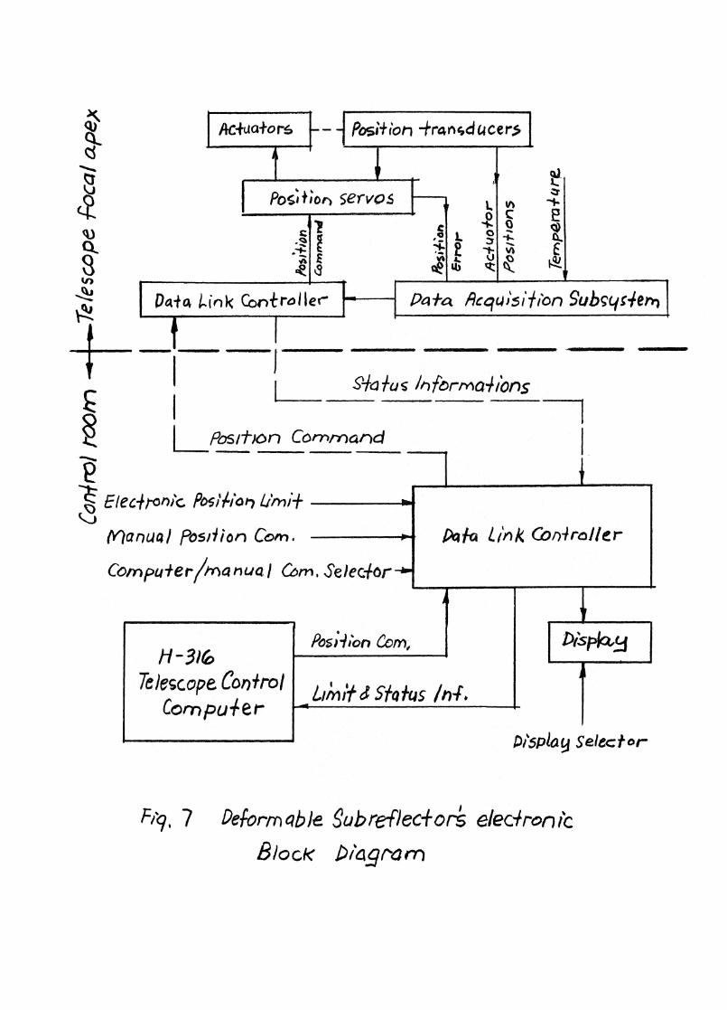
For the completeness of this report, a block diagram of the control
system is included for reference, illustrated in Figure 7. Each actuator's
position is monitored by a LVDT (Linear Voltage Displacement Transducer).
A position given by the computer is compared with the measured position.
16
The difference of these quantities is reduced to an amount of + 0.01m.
The commanded position is up-dated by the output of the computer while
the telescope tracks a source. The up-date rate is set to be 1 new posi-
tion per second.
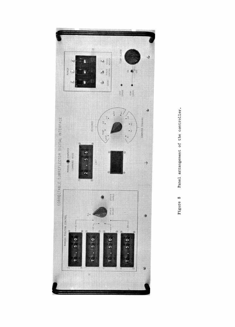
Figure 8 shows the front panel of the controller. The controller is
an interface between the H-316 on-line computer and the servo mechanism.
It's functions are receiver and transmitter data. Presently this interface
is connected to the power supply at the focus by cable and no. 45 and 34
in the control room.
The interface provides the option of manual and computer control.
A switch for this selection is located in the upper center of the panel.
Upper travel limit of 2.56mm is displayed under this switch. A dis-
play of travel in mm is located below this 'limit' window, with the select-
ing switch located on the right.
It is possible to monitor the commanded and measured positions of
actuators Al thru A4. It is also possible to monitor the temperature at
the LVDT in Celsius. Heating elements are provided to the position trans-
ducer to maintain continued level specified by the producer of the trans-
ducer.
The display of 'LOCK' is for debug purposes. It shows the differ-
ences between the sum of the commanded positions and the sum of the actual
positions.
The manual control enables one to input values into the thumb wheel
knobs, either individually or as a group (switch to 'ALL'). The step is
executed by pressing the 'UPDATE ENABLE' button.
17
All actuators are travel from an undeformed position to a prede-
termined direction (see Table V). The deforming option is applicable only
for the K-band maser receiver.
The size of the actuator depends on 1) the force required to produce
the given amount of deformation on the subreflector; 2) the weight of the
subreflector surface and 3) the dynamical force due to the periodic tilt of
the subreflector in the beam-tilting mode.
As shown in eq. (8), the range of actuation from 200 elevation angle
to 900, based on the measured value of astigmatism, is 4.3mm. Refer to
eq. (2), that the stiffness of the shell structure when actuated in a
astigmatic deflection, is 201 Wm. The force required for the full actua-
tion is
F (astigmatic) = 4.3mm x 201 N/mm = 864 N(194 lb) (14)
The weight of the shell is 668 N (150 lbs). Assuming that the weight
is equally distributed to the eight connections, the force on the actua-
tor due to dead weight is
F (dead weight) = 668 N/8 = 83 N (19 lb) (15)
The force due to the beam switching at A = 2.0 cm is derived as
follows:
B (HPBU) = 1.2 X/ D = 57.92 A (sec)
0 (beam tilt) = 3B
18
x M a (Rotation of the subreflector) - 1.15
- 8.13 e
T (transition time) = 40 ms
T (available torque) = 7000 ft-lb
4a 2A (angular acceleration) = --
2-= 34.3 rad/sec
lb-sec2
m (mass of the shell per connection) = 1501b/8 = 19 lb = .049
d (distance to the axis of tilt) = 39 in
F (beam tilt) = m-A•d = 294N (66 lb) (16)
The total force required for each actuator is the sum of the force
shown in eq. (14), (15) and (16), or
F (total) = 864+83+294 = 1241N(279 lb) (17)
The experimental version has actuators rated at 100 lbs. This
force was amplified by a factor of 2 by lever arm linkage, having rated
output of only 200 lbs.
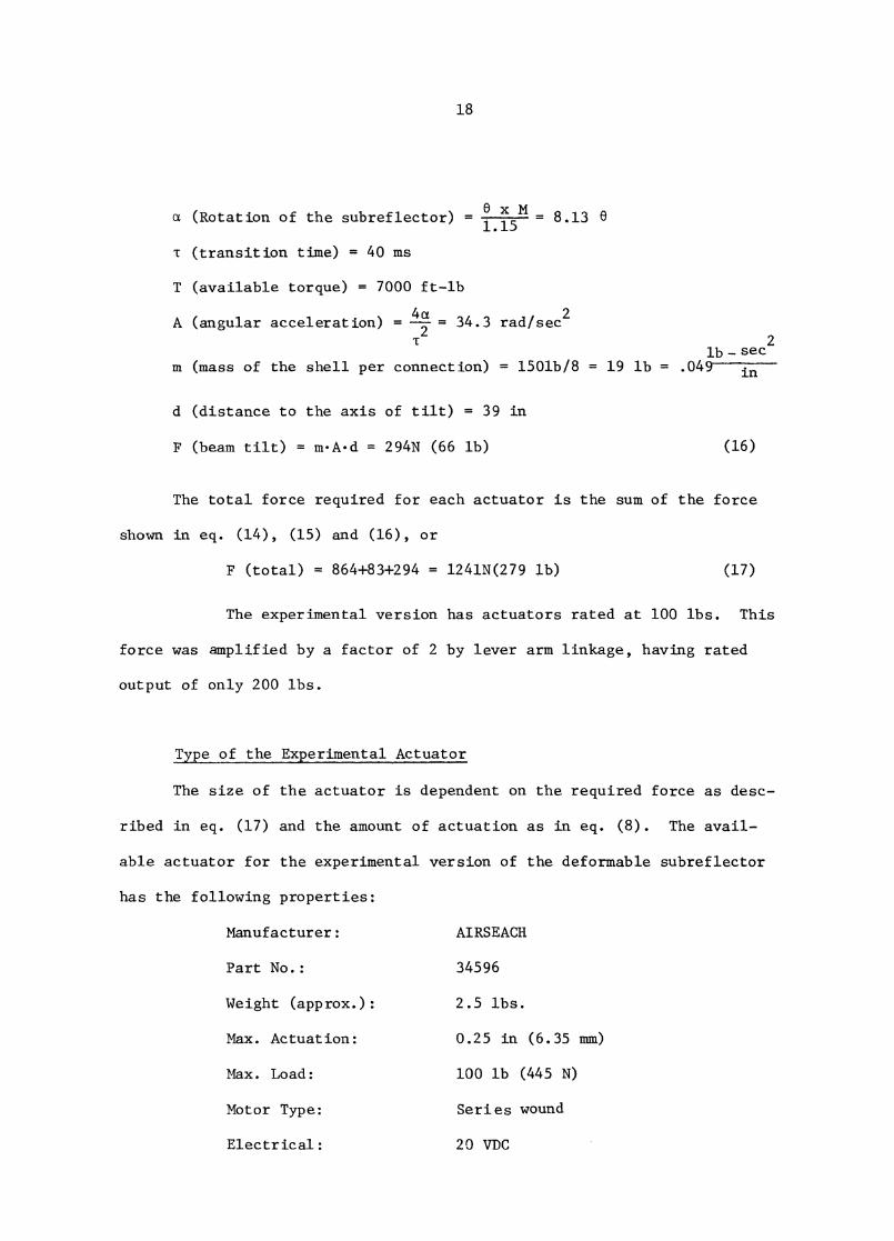
Type of the Experimental Actuator
The size of the actuator is dependent on the required force as desc-
ribed in eq. (17) and the amount of actuation as in eq. (8). The avail-
able actuator for the experimental version of the deformable subreflector
has the following properties:
Manufacturer: AIRSEACH
Part No.: 34596
Weight (approx.): 2.5 lbs.
Max. Actuation: 0.25 in (6.35 mm)
Max. Load: 100 lb (445 N)
Motor Type: Series wound
Electrical: 20 VDC
in
19
The Linkage
The necessity of this linkage is due to the motor actuator available,
in conjunction with the requirement in force and displacement of the sub-
reflector. The final version of the deforming system could by-pass this
linkage to reduce the additional deflections.
The extension of the lever arm also provides an amplification in the
travel of the LVDT.
The Switchin Off of the Actuators
The subreflector deformation can be terminated either at the commence-
ment of an observation; or if erratic behavior is detected, such as the
monitored amount of actuation being different from the commanded quantities;
or the temperature readings at the actuator motors show a level higher
than a preset value.
The proper sequence is 1) to set all actuator command values to
0.50 mm at the four windows on the left hand side of the panel; 2) switch
the "manual/computer" switch to the manual position; 3) put the update
selection button to "all" position and 4) press the "update enable" button.
This will activate all actuators to drive the surface back to the undeformed
position. These positions will hold even if the power supply is turned off.
20
IV. BACKUP FRAME
General Description
The backup frame of the deformable subreflector provides the follow-
ing functions: to add structural stiffness to the subreflector; to inter-
face the subreflector to the existing beam tilting device; and to support
the actuators-linkage combinations.
The subreflector is connected to the frame at eight points. Four of
which are actuated by electro-mechanical devices, labeled as Al thru A4. Another
four conhections are mechanically fixed with rods and brackets, and labeled
as S1 through S4. Figure 1 shows the schematic arrangements of these con-
nections, and appendix B shows the detail. The stationary and the actuated
connections are alternately arranged for the astigmatic deformation of the
subreflector.
The subreflector-frame combination is attached to the beam tilting
device through two bearings and two connections to the push rods. These
connections are designed for quick installation so that the telescope can
be operated in either prime focus or Cassegrain system. All connections
are positioned beforehand by pins so that calibration procedures are kept
to a minimum after the subreflector is installed.
The Design
The material of the frame is aluminum. The limit of design is not
governed by the allowable stress but by the total weight and moment of inertia.
The detail of the design is included in Appendix B. The analyses of the struc-
ture is summarized from the detailed computation of reference [8] and listed
as follows:
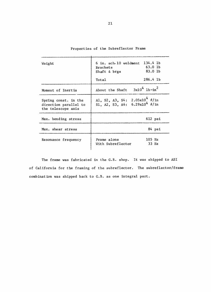
21
Properties of the Subreflector Frame
Weight 6 in sch.10 weldment 134.4 lbBrackets 63.0 lbShaft & brgs 83.0 lb
Total 286.4 lb
Moment of inertia About the Shaft 3x10⁴ lb-in2
_
Spring const. in thedirection parallel tothe telescope axis
Al, S2, A3, S4:Si, A2, S3, A4:
2.05x10⁴ Clin
6.29x10⁴ ii/in
Max. bending stress 612 psi
Max. shear stress 84 psi
Resonance frequency Frame aloneWith Subreflector
105 Hz33 Hz
The frame was fabricated in the G.B. shop. It was shipped to ASI
of California for the framing of the subreflector. The subreflectoriframe
combination was shipped back to G.B. as one integral part.
22
V. SOFTWARE PROGRAMMING
General Description
A subroutine was added to the 140-ft telescope control program in
the Honeywell-316 computer by Bob Vance. This subroutine gives the
user the option of using this deformable subreflector by switching on the
power supply of the servo control electronics and setting the manual/
computer switch (see fig. 8) to the computer control mode.
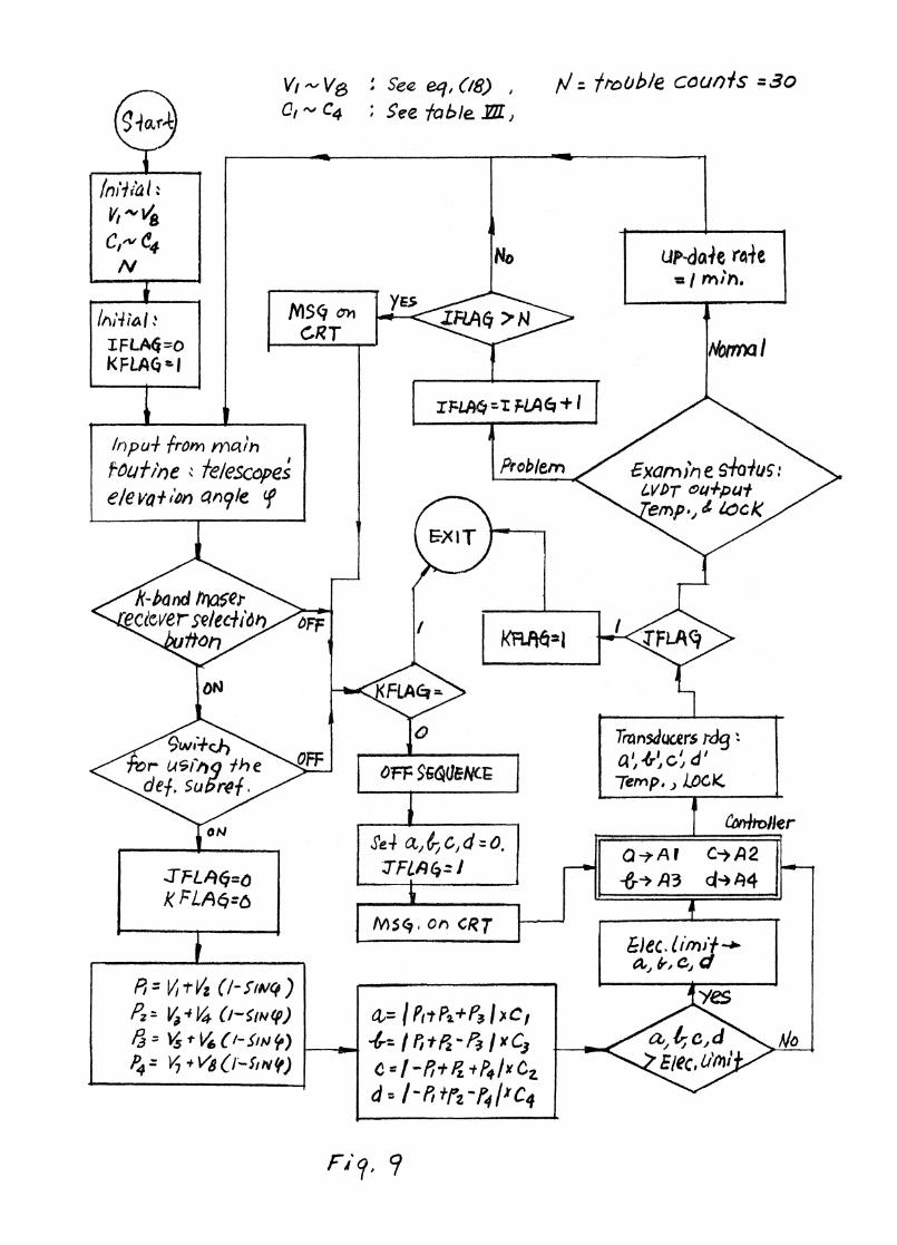
This subroutine was written based on the algorithm illustrated in
figure 9.
The Input and The Output
The amount of actuations on the subreflector surface is dependent
on the elevation angle 0 of the telescope. The values 4) are readily cal-
culated by the main control program.
There are four outputs from this subroutine: a, b, c and d. Each
is a eight-bit word, containing a max. value of 255. These outputs are
channeled to the controller, and ultimately translated into displacements
of the subreflector shell. The expressions in eq. (18) are modifications
of eq. (6), with zero crossing set at 0.50 mm:
P1 = V
1 + 2 (1-sin = -0.578+5.446 (1-sin (I))
P2 = V
3 + V
4 (1-sin (1)) = 0.
(18)P
3 = V
5 + V
6 (1-sin = 0.
P4 = V
7 + V
8 (1-sin (1)) = 0.
and subsequently, the four output words are expressed as:
23
a = (P +P +P)xC at A1 2 3 1 1b = (P
1 + P
2 - P
3) x C
3 at A
3
C = (-P +P +P)xC at A1 2 4 2 2d= (-P +P -P)xC at A1 2 4 4 4
PI represents the first order astigmatic deformation. P2 thru P4 are
values for higher order deformations, which are not being con-
sidered during the design phase of the subreflector. Presently P2 thru P4
are dummys and the values of P 2 thru P4 (or V3 thru V8 in eq. (18)) are
set to zero. These values can be redefined once it is proven that the sub-
reflector is capable of these types of deformations.
thru C4 are calibration constants, correspondent to actuatorsCl
A1 thru A
4. The numerical values of C 1 thru C
4 are listed in table VII,
column 6.
(19)
24
VI. MEASURING JTG
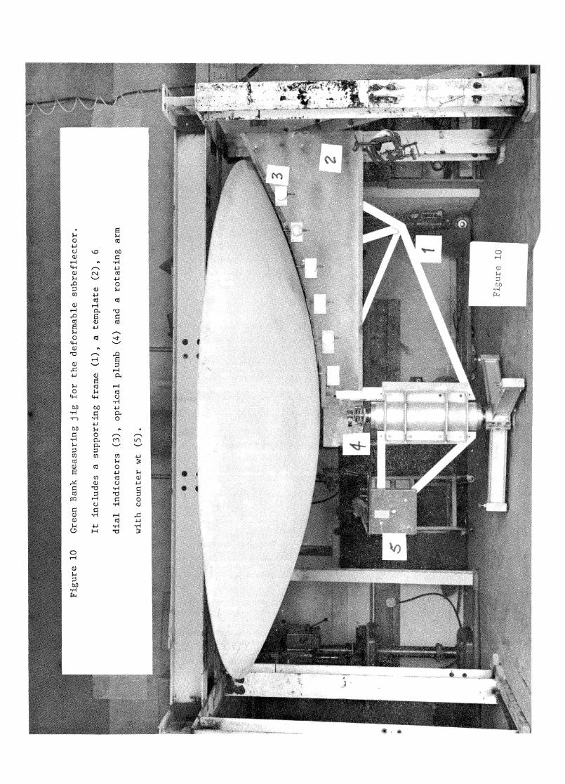
Fig. 10 shows the general setup of the measuring jig, with the detailed de-
sign included in Appendix D. It consists of a supporting frame for the sub-
reflector and a template. The measuring jig serves the following purposes.
1) to verify the subreflector's surface accuracy,
2) to measure the contour of the deformed subreflector,
3) to evaluate the efficiency of the actuators, and
4) to provide a reference system for future adjustments.
The subreflector was held in place and was so adjusted that its
hyperbolic axis is aligned with gravity. The central axis of the jig is
defined by an optical plumb, with the three adjustment screws at the sup-
porting legs to correct the tilt, and mild forces required to shift the
jig in lateral direction so that the axes of the subreflector and the jig
are coinciding. Few repeating cycles are required until these two axes
will actually meet. The optical plumb defines the direction of gravity,
and with an eyepiece to collimate the central mirror of the subreflector.
The horizontal reference of the template was monitored by an op-
tical level (Wild N3) to insure the line remains horizontal as the jig
rotates. There is no fine adjustment for the counter weight, but good
balance can be achieved by using heavy bolts or nuts clamped on the jig.
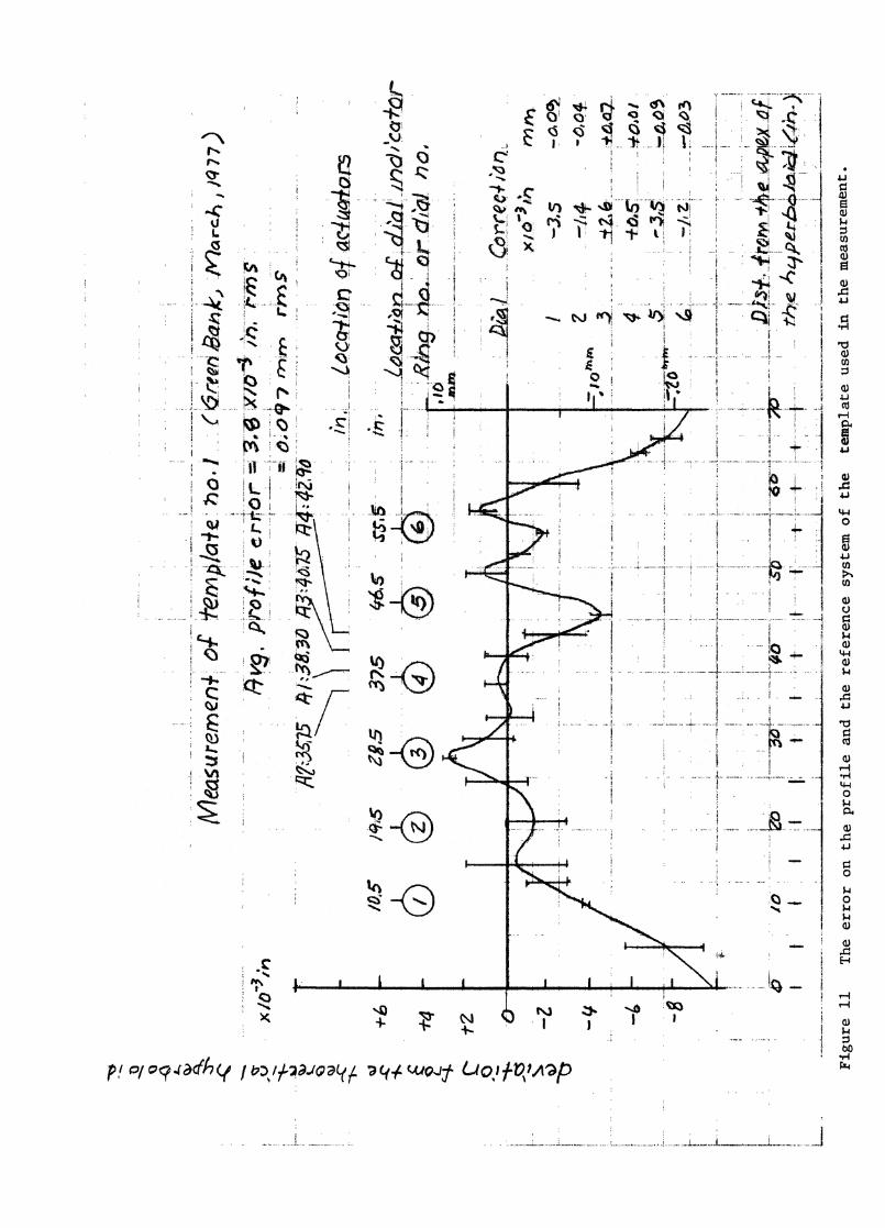
The 1/8 inch steel plate template has a cut-out hyperbolic profile.
This profile was also measured by optical means so that the reference is
well established. Fig. 11 shows the arrangements of the dial indicators,
the reference profile and the proper corrections for the zero readings of
each dial.

25
The dials are placed on the template vertically. The dials are
product of MITUTOYO, part no. 3052. The graduation is 0.010 mm. The
total travel is 30 mm.
There was no effort to evaluate the accuracy of the system. Rough
estimates of the measure accuracy is about + 0.050 mm.
ACKNOWLEDGEMENT
The author wishes to thank the Green Bank workshop, under the
supervision of Albert Steinemann and Martin Barkley, for the assembly
of the subreflector stiffening frame; the maintenance group with Ron
Gordon, Don Gordon and Herb Hanes for the mechanical work; Sidney Smith
for the help during the measurement of the surface. The Controller was
designed and assembled by R. Lacasse of the Electronic Division. R. Vance
was responsible for the programming. Also thanks for advice from R.
Fisher. The moving force of the project shall be accredited entirely to
Dr. S. von Hoerner.
26
REFERENCE
[1] S. von Hoerner and W-Y. Wong, "Gravitational Deformation and
Astigmation of Tiltable Radio Telescopes", IEEE Trans. Antennas
Propagat., Vol. AP-23, pp. 689-695, 1975.
[2] S. von Hoerner, "The Design of Correcting Secondary Reflectors,"
IEEE Trans. Antennas Propagat., Vol. AP-24, pp. 336-340, 1976.
[3] P. R. Cowles and E. A. Parker, "Reflector Surface Error Compensa-
tion in Cassegrain Antennas," IEEE Trans. Antennas Propagat., Vol.
AR-23, p. 323, 1975.
[4] S. von Hoerner, "Measuring the Gravitational Astigmatism of a
Radio Telescope," IEEE Trans. Antennas Propagat., Vol. AP-26, pp.
315-318, 1978.
[5] R. J. Lacasse, "Correctable Subreflector Controller," N.R.A.O.
Electronic Division Internal Report No. 193, 1978.
[6] S. von Hoerner, R. Fisher, W-Y. Wong, "140-ft Observations with
Deformable Subreflector," N.R.A.O. Engineering Division Internal
Report No. 109, 1978.
[7] Peter J. Napier, "Cassegrain System for 140-ft Telescope," N.R.A.O.
Memo, 1972.
[8] Computer output file no. DS-001, "N.R.A.O. Stren Analyses of the
Subreflector".
[9] Computer output file no. DS-002, "C.D.C. Stress Analyses of the
Subreflector, Dec. 28, 1976.
[10] C.D.C. Report, "Stress Analyses of A Deformable Subreflector",
Control Data Corp., Dec. 28, 1976.
27
[11] S. von Hoerner, "140-ft Deformable Subreflector", N.R.A.O. Memo,
October 28, 1975.
[12] Computer output file no. DS-004, "Antenna System Inc. Surface Mea-
surement",
[13] Computer output file no. DS-005, "Green Bank Measurements of the
Deformable Subreflector".
[14] Computer output file no. DS-003, "Green Bank Measurements of the
First Subreflector".
2 8
LIST OF TABLES
TABLE I SUBREFLECTOR EDGE COORDINATES. DEFINITION OF ANGLE 0 IS
SHOWN IN FIG. 7, LINEAR DIMENSIONS ARE IN INCH
TABLE II MATERIAL LIST OF THE SUBREFLECTOR
TABLE III ANALYTICAL RESULTS BY CDC
TABLE IV ERROR CONTRIBUTION OF THE SUBREFLECTOR
TABLE V LOCATION AND SIGN CONVENTION OF THE ACTUATIONS
TABLE VI G. B. MEASUREMENTS OF THE SUBREFLECTOR SURFACE
TABLE VII EFFICIENCY OF THE ACTUATORS
29
TABLE I. SUBREFLECTOR EDGE COORDINATES. DEFINITION OFANGLE cp IS SHOWN IN FIG. 1, LINEAR DIMENSIONS ARE IN INCH
Z(R) c1 R Z(R)
-90.000 67.842 19.187- 88.000 67.839 19.185-86.000 67.827 19.179-84.000 67.809 19.169- 82.000 67.783 19.155- 80.000 67.749 19.137-78.000 67.708 19.114- 76.000 67.660 19.088-74.000 67.605 19.058- 72.000 67.543 19.025-70.000 67.473 18.987-68.000 67.397 19.946- 66.000 67.314 18.901-64.000 67.224 18.853- 62.000 67.128 18.801- 60.000 67.025 18.746- 58.000 66.916 18.688- 56.000 66.801 18.626-54.000 66.681 18.561-52.000 66.554 18.494- 50.000 66.422 18.424- 48.000 66.285 18.350-46.000 66.143 18.275- 44.000 65.995 18.197-42.000 65.843 18.116-40.000 65.687 18.034- 38.000 65.526 17.949-36.000 65.362 17.862-34.000 65.194 17.774-32.000 65.002 17.684-30.000 64.847 17.593-28.000 64.668 17.500-26.000 64.487 17.406-24.000 64.30 17.310-22.000 64.117 17.214- 20.000 63.930 17.117-18.000 63.741 17.020-16.000 63.550 16.921- 14.000 63.357 16.823- 12.000 63.164 16.724-10.000 62.970 16.825- 8,000 62.775 16.526- 6.000 62.580 16.428- 4.000 62.386 16.329- 2.000 62.191 16.231
0.0 61.996 16.1332.000 61.803 16.0364.000 61.610 15.9406.000 61.419 15.8448.000 61.229 15.749
10.000 61.040 15.65612.000 60.853 15.56314.000 60.669 15.47216.000 60.486 15.38318.000 60.306 15.29420.000 60.129 15.20722.000 59.954 15.12224.000 59.783 15.03826.000 59.614 14.95628.000 59.449 14.87730.000 59.288 14.79932.000 59.130 14.72234.000 58.976 14.64836.000 58.827 14.57638.000 58.681 14.50740.000 58.540 14.43942.000 58.403 14.37444.000 58.271 14.31146.000 58.143 14.25048.000 58.020 14.19250.000 57.903 14.13652.000 57.790 14.08354.000 57.683 14.03256.000 57.580 13.98458.000 57.484 13.93960.000 57.392 13.89662.000 57.306 13,85564.000 57.226 13.81766.000 57.151 13.78368.000 57.082 13.75070.000 57.019 13.72172.000 56.962 13.69474.000 56.911 13.67076.000 56.865 13.64978.000 56.826 13.63180.000 56.792 13.61582.000 56.765 13.60284.000 56.744 13.59386.000 56.728 13.58588.000 56.719 13.58190.000 56.716 13.580
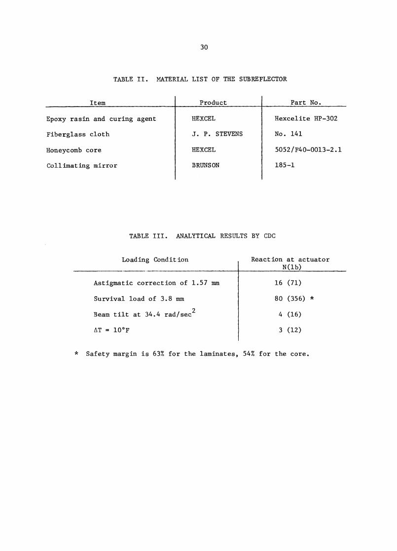
Loading Condition Reaction at actuatorN(1b)
Astigmatic correction of 1.57 mm
Survival load of 3.8 mm
Beam tilt at 34.4 rad/sec2
AT = 10°F
16 (71)
80 (356) *
4 (16)
3 (12)
30
TABLE II. MATERIAL LIST OF THE SUBREFLECTOR
Item
Epoxy rasin and curing agent
Fiberglass cloth
Honeycomb core
Collimating mirror
Product
HEXCEL
J. P. STEVENS
HEXCEL
BRUNSON
Part N
Hexcelite HP-302
No. 141
5052/F40-0013-2.1
185-1
TABLE III. ANALYTICAL RESULTS BY CDC
* Safety margin is 63% for the laminates, 54% for the core.
Actuator
Al
A2
A3
A4
Location
North
West
South
East
Edge Movement
31
TABLE IV. ERROR CONTRIBUTION OF THE SUBREFLECTOR
Source ] Error (inm rms)_
Residue path length error after astigmatic correction
Deflection of the frame, linkage
Manufacturing error of the surface
Electronic
TOTAL
TABLE V. LOCATION & SIGN CONVENTION OF THE ACTUATORS
+: deflect towards the main reflector to shorten the path length
-: deflect away from the main reflector to lengthen the path length
0.26
0.34
0.25
0.04
0.50
16% 26% 58%
17% 25% 58%
18% 15% 67%
15% 35% 50%
63% 60%
62% 60%
69% 68%
54% 52%
Avg 60%
C
1
= 167
C2 = 1.67
C3 = 1.47
C4 = 1.92
32
TABLE VI. G. B. MEASUREMENTS OF THE SUBREFLECTOR SURFACE
Date
12- 5-77
12- 7-77
12-13-77
12-14-77
12-14-77
3-15-78
3-15-78
3-15-78
3-15-78
Measurement
GB2-2
-3
-4
- 5
-6
-12
-13
- 14
- 15
Error (min rms)
0.21
0.21
0.21
0.26
0.22
0.26
0.24
Actuation (mm)
•••••••••
•■■■••
2.54
■11.1."11.11
1.94
•••••••••
Actuator
A-1
A-2
A-3
A-4
TABLE VII. EFFICIENCY OF THE ACTUATORS
Frame Linkage Direct IndirectDeflection Deflection Measurement Measurement
1 2 3 4
CalibrationAvg Constant
5 6
FIGURE CAPTIONS
Figure 1 Schematic drawings of the arrangements of the 140-ft telescope
Cassegrain system. The general dimension of the deformable
subreflector is given, and its relative position to the main
reflector when the K-band maser receiver is in use.
Figure 2 Finite element model used by C.D.C., contains 180 elements,
108 nodes. The subreflector is considered symmetrical, ac-
tuated at nodes no. 52 and 62, and held at no. 57.
Figure 3 Comparison of the deformed subreflector profile to the best-
fit deviation of the main reflector at elevation angle of 28°
with the radius of the main reflector normalized to 62.3 inches.
Figure 4 Comparison of rim deflection of the deformable subreflector
with the telescope positions. Dashed line denote the analytical
results of 0 db, 9 db and 15 db edge taper. Solid line shows the
measured result with an elongated feed. Ao denotes the de-
sirable range of rim deflection; A3 shows the range presently
covered by the experimental actuators.
Figure 5 Profile contour of measurements GB2-4, GB2-14 and GB2-15, with
contour level of 0.005 inch.
Figure 6 Comparison of the commanded actuations (vertical scale) and
measured deflections (horizontal scale). Solid line is
the measurement, dashed line is the ideal.
34
Figure 7 Deformable subreflector's electronic block diagram.
Figure 8 Panel arrangement of the controller.
Figure 9 Subroutine flow chart implemented to the telescope control
program.
Figure 10 Green Bank measuring jig for the deformable subreflector.
It includes a supporting frame (1), a template (2), 6
dial indicators (3), optical plumb (4) and a rotating arm
with counter wt (5).
Figure 11 The error on the profile and the reference system of the
template used in the measurement.
Fi'et
ILO
elece's
474-/:r.07its,
V iew from .the kopof The 14cY--f-1. -tele6c,ope
No-fa fico(1) -444 :
Acq uaieci cuppo)450611-/g4:
S ikalionory cuppori5
0Coll "mai p.s tn;rror
Sec4fon thrt.1 ,Eobrefleckorplone Leimmegin
y4 NRAO SUBREFLECTOR
107
106
104
103
9 it. ga 1 / I 62 4'7,.. 82 i 92 \\,,k7.......-----7•
%
---_*.......... I / 73 149 // ‘, "le:1 1
/I 54 \ / 48 , , ; , \I , 44 / .... ,.;iee 72 , 61 ....),c4.5 °
1 // 1' 63 /31(..'• / 74 1
■it I 4.6' I '''' , /35........ / N.
■ I ,
/ 1 ,...i. I ,
' i • 1 \/ i ‘ '.
1 \ i.,
lae N. \
1
I
81 / • "al \ /
, ,...511_ 112 / \ 122 // \ 153 / \
i 91 %/ \
I 102 \iu..4 a .... _ i \I _1173/_92 _ \_lx.,4
/42 • I
12 76.....3 .... I/ tat
i
i •/ • / / •
••
1 ‘ //75
/ \
• /
• 53 1 43 ;A‘‘ " // 6CI ‘‘ 445,,....---- /-.‘41t: - - - - - \.W/
-_ •• / 17369-----._,....‘e- ,, i . I
„ , ,cn ,\**15%---9
.1".-.--,• 39 / 1 •,.. I ,47 .....--)t / ■ ill i \ /21 II \ ---...
• / N.1 / ‘ &ig.,_ ....... / ,k, 1 \
/ 1 . 1 , \34•v / 1 36 .4(.2. ... ---
--1 70 1 \ I 90 \ / 100 ‘ \ `"". i\
.3/4. 100/ 59 \ / / 1/- 33 1 \ \ SS\ / 131 1
1. / ' 182\
\ i ____g. 21/21 ‘,9 *-'/ \ 52 1 \
ir- -- ..... 1 ,... / \ 142 ‘#)0...1 -- -- 4'1 - -----/7\-- ‘ g6
..... ‘, , 1411\I
23 ' % 1 9‘ 7 ----- ' Y7 /
1 5 1 # 27 I 21 '',_.'12•.`"........''./ \.."-".."*-'.."`" 4.52-"...'"'"..•• If. \54/ 99 \/28 1
1 /#i1 ,, i/ 1 22 "*.''g
\ 5' 46
i1 32 /I 37 \\ 1 •'# ‘ 69 /58
\ ,/ ‘ 110
-0\, / \ // 89\ / ‘ %
• (3\ /
/ \ 120 i 15,:. 1\ :: 172
/i.... .....
, 1.2 9c / • • / %, / 1 .... _ :fit• /I 1 1 ..Y4 •,Vt" .-.... / 1 ■is .0 ' , N. 1 .....',
.1C‘ 31 / • 51/
\ 68 / •/ / 78 •-. .--"-*`-, It/ / 12 \ ‘..,, i 2g \ i
i 36 ■ i/41
\ / 57 \ // 109 "*;? '''' ■ 130 \ /# I 99
. / \ / \ / ..........92,....... 42 I , 1, I .
' '' % / /40 1''' ,,,-,75/61/ as ,/t7 ; /
g...... 1k16 / 11 • 12_...-2*(2. 1z/
/ .x- t 67 "I' "'..*"`..I\
/,
a. i 119 ,/t-,, /6 rr
• 1 .....-~"/ ,, 25 / \ 30 s '-.. . 1
• :; u I / I ...It
a. 15 )r.I.5 I /,,,, ‘ ,/ 1 „. i •,, I . 1 77■ I /# i ...,, 1 s. • 19 \ „1' i •,1 56 I1,‘ 4, . .■
c , 1,/, ‘ .„.6 ........,;-,y...... „ • \ . 35 1 50 )1" -%1 •*/ I 171
I/ I '''''.....
II
A4'''''o- ; 108 '' ''''ITI4 129 1 t 5a ,"I .1)7,4f ." � ‘ ``' ‘ n2 Jt
e.'"f "^"
."3'
T -1 4 / 1 24----;*1:7 I s I 66 * '.7 1 #■ # I •
'i
i \., A ‘ ■
/9 li Ls, -ra 1 1 ,fr-, I ' 40 1 'Sei I -76-'-, 1 1/ I .-' 7 0 . 139. I 168.
I / %■.., I `...
2.a". 140 163 '■ 1.7e 85 ...
Figure 2 Finite element model used by C.D.C., contains 180 elements,
108 nodes. The subreflector is considered symmetrical, ac-
tuated at nodes no. 52 and 62, and held at no. 57.
• 18
80
.2.." .
• 9.Z......---# /....-IC., 7 \ / % --4e 1 ‘ 165 /e/ " 135 •., tu,...--° 1/ % 105 ,,n- .., I 1• . // •1 • i ..... ,...-"" I \\ 155 12 % 1 \
\p % , I
144 \\\ I
/ 175-_,...........----- ......ifro% / 115 1 104 „..""51‘ c
71,..! ".. 1 •■• t
• 96 1 1 -.4',... l .... I 124 ; .
; /34 \ I• / 95 1 •„_191 1021, / ••• 1''',.. 1 114...# I
. N.\ I 5 ,, /1
■ kw _ ., - -----7C66
%/ ' / ,8 I e 1 I 103 . i .........-- -/C \
% s I 94 , ■ 1 ..les_-- I ., 154 // \ 16451 VO 1 / 84 I 4, 1 . /; . I \---)6 , I „/'' . I ,,.--"" / ‘ 123 I e, \ ‘ / , ‘ /65 / • I 93 _x(P i /4., ‘ / 174/ 64 / I °"°'•......... 1
4,8 83 i ••••• -i' 113 i \ i 133 ‘
I
‘
• 138 / • ---"--/ 157 % 146 N'...._*9.3 1■126 //
\ 137 / I /66 1
/t .ea'- " ‘
Na■ .e'. . 176/ • / v 74 • 7'3 \ / 1361 .;*".)16,,. 156 .----X---__ ■ 72' 126 . It 145 ■ ; ..---,,,, / \ --314-, 1 .• .1 .. . .wil • 106 / 1 '''•-,,, 1 •• .,,/ \ /
'.\ /80 #
/ %
\ / •170; / • 179
/.
%• // 169 \• . %97 •)?8 • /. 1/ \
-----___....•_gs/ 158 • 178 ,,,, 1.05.... -........
149/ \ )E.... % 4,49 I/ \ 148 / . .... „• % . 1/ „/ \ ...... 1 ..,'"i 159 \ / 167 177-..,, I
/ • 147 1/ ./1-.....5 ‘ / 158 % / 1 ■..,,,----- 2 4 % # 1 ■/ .---.
gm. fingicifitcal1.111101111111101110111111411P
I <leg I1 =c(i)z•eas red
Loccrt-ion oaf ac4ucti7on
pi) aisica
76 e preetri experepierita I aciutricr,
k Z4 """%Fee el, (a)
(Y)
15o
1110..
rna,11, eel lec4or3 devt'o- t 7Crarn il EP (3411 value5)
/9 no itri- ka I (E/ev. z: 28 c)(RE14413)
S'obreif eCibr prOf e ,,aduate4 bg /57 mm
Figure 3 Comparison of the deformed subreflector profile to the best-
fit deviation of the main reflector at elevation angle of 28°
with the radius of the main reflector normalized to 62.3 inches.

Das
hed
line
den
ote
the
anal
ytic
alw
ith
the
tele
scop
e po
siti
ons.
.1
m
easu
red
calc
u +
ed
db la
per
201 V
Ihz
9 d
i) t
aper
, 5d6 a
p e
r
Ze3'
d/-
3//
)47 )
-A7
2 (
9,7
ed
ge
-/p
er)
.2.3
•41
.5.6
IJ
II
8o
7ø
40
504
0.3
0
.7.9
/.0
-sir
) Co
ct= 7
23 (/-
f o)4
1)--
A17
a= 7
,33
(I-
Sii)
r)-
4z8
(eel
: 1?E
/401
3)
Ele
v. A
ngie
C P (
de
Figu
re 4
Com
pari
son
of r
im d
efle
ctio
n of
the
defo
rmab
le s
ubre
flec
tor
4,
resu
lts
of 0
db,
9 d
b an
d 15
db
edge
tap
er. S
olid
lin
e sh
ows
the
mea
sure
d re
sult
wit
h an
elo
ngat
ed f
eed.
Ao d
enot
es t
he d
e-
sira
ble
rang
e of
rim
def
lect
ion,
A3 s
how
s th
e ra
nge
pres
entl
y
cove
red
by th
e ex
peri
men
tal a
ctua
tors
.
.153 2-/4 Deformed surface
Ail R3
R2, 4.
Where,' — ' means kigiherof po4k) and 14'
ShOrten ir25 0-f P24h
/er19-70),
-/ 1 94 Thrn
Surface, error = 0, Z4 Thrn rMSZS X asOZThrn4y 44. 04- mri
gd3 rnrn
19)( = -40.2 � /6-6- rad.
19r 29,o /0--7 rad.
Fief
Measuremen4 3454 - FrtNo, paraire4er5
6B2-4 Relaxed sur(ce
Surface error = 0,21 mm,6x = 0,o4 n--)mAy ---- 4/05 n m
777 fnt9x = 271 )(to' raci
Oy
662-1 alaxed surfetce
,4
A-I
,Dia
lGA
-3 , d
Ial 4
A-3
, P
iot
6
A-2
, O
W 4
4-2,
9101
A-4
,D
ial
411
4,01
01
Com
pari
son
of c
omm
ande
d O
th4a
-Won
4 (v
erbt
al S
cale
) M
easu
red
deli
edd'
ons
(hor
izon
tql
scale
), g
ond
tk)e
, m
easu
rem
err
, da
ch M
I6 I
s7
111e
zV
eal
F19,
6
Pos;+;or) 5ervos
ciztE
.2Z
Deli a, k Con+ ro lier
Ac4aa+o r6 MINN.
Posi+('or) -fr4114ci4cer
Lin --1.bo ii E
,6 Le 1; -,--: a.co
tIF 44) ki k 0-
Paha Requ;6171/bn gubv1c4eAl
osmimmi.■ satmenaiwiMmlimi WilliN11110111111/111011.1111110111111111r 11111.110111,111MiNIONOMMINVOINIMP 1.011.01111113111XIBMINSIMIN. ilIONININVOISONOMMIS.
z Gia his / forroa4 ions
, Posrhon Command
Elec-ttonic P051A1017
&Oa 1,1hk G21)-ire3lierntial posli corn
Com puie /ina ua 1 COM Selec-for
AMONININIMONOINIMNIPMEN....1
-316,Te 16CCope Conirol
Corn pu4 er
Pod-1;0n Corn,
ZdMitt S74ivs
Pispict-M
1)15play Selector
Deform (lb le gubrefleofor elecfron
Block ,i)149(-0 rn
e
Fig
ure
Pan
el
arr
an
gem
en
t o
f th
e c
ontr
oll
er.
VI — Ve See eq, (/8) , Is/ troOble CouOiS =30C4 ; ee to b 1e.
PAS§CAT
YES
up-da.le rah
/
IL I FIA4 4- 1
Examine S-toittC:I.VP7 entipuiemp,1
4C ZOck
Problem
If-band hia5v)-ecioverselecli0t)
tfroti
KFLA4
OFF 966WENG
Trznsducers rag4 Ir, ic`
Temp. ) kocK,
C6n4tolierohl
Se4 ex4,c1c1FLA 4.= I 01111110..-.-0
C 2
/43 :49 /4
m5§ , Oh CRT&Mc.a„, 6-, cf
Jori110111101111......somm...., 41.1.1.1.1.0.1.114.111111111111111M.1•1111.0011111.
ai= I Prt P2:4 P3 Ixc
-4-r-IfitPz-P3IYC3-8.0i-tP4,1xCz
I-Pitrz-f411C4
F ?
Fig
ure
10 G
reen
Ban
k m
easu
rin
g j
ig f
or
the
def
orm
able
su
bre
flec
tor.
tem
pla
te (
dia
l in
dic
ato
rs (
3),
op
tica
l p
lum
b (
4)
and
a r
ota
tin
g a
rm
wit
h c
ounte
r w
t (5
).M
gt
'-"tk
14
4:0
0"A
'
10
' 4 41
1, 51
14
. .
.-**/%
379,,
,e
tire
men
+l'e
mpla
ie o
.J (
6r(
eo
Mar
cb I
14
77
)
i9v
8, p
rofi
le c
ri;c
ir6
wer3
rifn
Sr
=. 0
.0y
? f
ru
"-,
rmS%
Iliz 34
75 4
1 z3
8,- 365
z 4075
194
;42-
.9-4
\‘)t6
ect
ion
of a
c4t,
Ari
of3
•••■
•••-
r.
1071
401
•2
iL4A
ta_
4-1 16
'40,6
'iiZ
L_7
15
-403
•
_iro
m -f
itle_
4421
0x Ja
itiz
e el u
iper
bst'› . A
a.t .ci
ti, ar0
^•
,
r
-4
Str
iIf L
--t-
_C
orre
lei I
T,
(C3t
bil
-15
—14
-404
-
18,5
37
544
.5"
.m6
/05
14?
(j)
tr,L
eC
aii
i/ri
ma
Ind
I ' C
olla
r-
CV
O/
Fig
ure
11 T
he
erro
r on t
he
pro
file
an
d t
he
refe
ren
ce s
yst
em o
f th
e te
mpla
te u
sed i
n t
he
mea
sure
men
t.

46
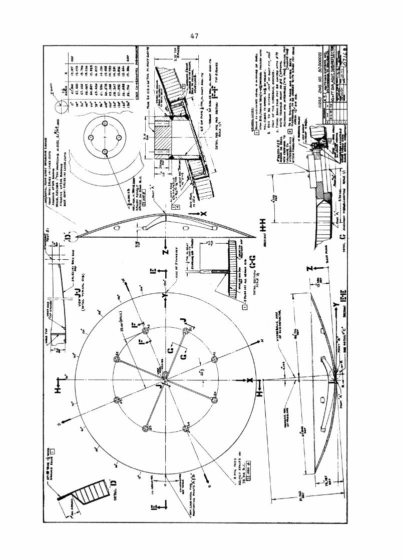
APPENDIX A
Engineering drawing of the Subreflector Surface
Ma
mtivft
os
SHI•
ovo
1194
4, 0
WS&
TY
PW
IIPP
Hot
* it
TYP
ATIA
oRPA
SIOT
POIN
T b 1
50
to 5.0
*TYP
AWAI
IIIIIN
1111
1111
1111
111
12:
oeV
oL
MA
. ARI
sum
150
co-o
eftw
AIS
S
Co.o
rtaw
aiK
6U
M T
ABLE
RIF
.LIN
e M
AIO
' Po
%•
PO
INT
ioW
lhis
p ot.
-rs
A 1
1
SA
2As
z
wP
lat
/dk
39.0
0 (S
acs.
)
PU*4
3o
o.D
.x L
a T
uk A
1.44
4o)
1t
40.
.750
AL,
:u4Y
R10
16.
3;:g
t.:44
C0c
_ io
-32m
r BolT
vikerm
AT45.f
.5
Swo
PZer
c.ni
t al
_- E
MU
Fal
i./
sEci
XEL
Yz e
Ack
3.4
3:75
TY
IME
100(
som
aft
.:ta
w 7
0111
/ "IA
A.
&M
c TO
osu
co
mt.
MO
Mey
com
a
S.5
00 'N
AIR
k11
4 5,1lL . *1
555
105.
4-7.
5
\—T0
1614
44 3
.0 o
aatt.
as 1
.40.
,AL.
ALL
OY
god
..
DET
AIL
fAb.
WS
PA
D S
EC
TIO
iuTY
P 8
flAce
s
PAIN
T
Zi
8 m
TA P
ADS
Eelo
Att.
Y S
PACE
D o
At
78H DI
A 13
.c.
4.1=
111
HY
ritio
t &O
ut. M
ata.
le 9
ASF
ILA
CTO
R.AW
AVIL
ICor
•stA
iSco
PIL
g1.2
42ea
r
poot
res
* ea
rAti,
Ca
Sta
tatl
PIN
OT
******* ,
**** *
***** *
** *
********* *
******
1.00
1%
SF
****
* *
**
****
****
***
"""
*.V
OO
,..
aloS
.XTI
AL.F
LAM
It SP
RAY
SWA
SC47
x11
Suas
mx
/Mo
or
6101
1, 3
PuEs
l41
LAW
S aO
TAA W
ally .
WP
SOS
54o5
04*
HeY.
CRL
FLEY
eARS
et Tlik
tiow
EY
Com
R. A
L 50
52 , 2
.11//r
rEak
itsA
ow
g.tiv
o 55
305
SON
WA
I4SA
CS 5
5454
SPI
tES
144 L
AYER
. 0.07
11
S SK
A,
PA
SS
K
SPLI
Es 1
41 S
AM
WO
OAS
PVI
EW(D
ETA
IL T
yPt c
AL.
Mg)
_440
3.0
180.
AX
IS O
F SM
NO
TEY AL
IA1
4.Lo
il-Ti
••
tlIPP
WAW
As ai
st 4
4442
5
•67
1.164
,29.4
81
559
Is*
67.5
3318
.073
300 5
7.
025 l
8.7
44
440 6
6.0
69
11.2
3560
. 44
.10
17.8
9)7$
0 4
3.4
54
15.6
759.
0 5 .
994
.435
‘o57
Ø15
.42/
Ino
59 ,
14.7
69M
r 5
8 .7
4714
. 211
Ise 5
7 .3
9243
.194
ie 5
6.5
96 I
L “
.le
e 5
5.1
45
13. 1
80 a
er
SIX
8 C
o-O
RD
SP
arr
tS 5
0848
5e04
-46 t
iNe-
ZZM
IIIJ-
cou.
H.7
SOH
L ta
p \
4 M
u:Es
sciU
MA
-Y„
SPA
CER
oho
2.os
o 31
. C.
.\
,„„-
---,
---
-,
e.
fisF
SAKS
14.
woad
■41 m
acP
lAxi
T000
MA
U 1
41 S
AL .A
toisv
A ANA
P‘
DET AI
L SE
CT.
..! ‘1
11SC
ALE
112
MAW
S
ga,
dgE
HE
RA
L N
oTE
s:
Soul
s A
s .A
.oau
/ED
55445 A
A, M
VO
S O
f SW
ILL
ePol
v 31
5/Fa
raM
.4 9
0140
410V
000S
AIL
IlO
ckaa
l YA
M
MIL
L Fi
ScAS
TO
AM
OS.
14
SY w
ahR
ol.,
t.S
To S
C 4
4#IT
1410
4 .0
075 o
r A
s, F
IT,
.05:
PEA
K o
r TI4
C. H
iPC
ILSo
Ut.
Aul
tFA
CR
.R
AP
#7,6
25.
pilic
lt FA
GS M
AT
IBS
Coa
TIM
v,rm
mam
a 04
EG
utY
.40
11E
7e5
.41 2
FVH
NT
os 0
4 C
OM
ON
AK
,11
1 e4 clog
liiM
a.A
14,4
1AA
vi4
$75
MIE
E.R
IcE
EP
io4ces,
cs
/NM
5551
4407
5 To
CA
LO
OM
M n
o#HY
PERS
OLJC
. Ax
isS
E 5
5405
55A
51 1
05
*P
sA
DM
'*M
OW
Uss
tr,s
oc.
1145
r540
14, T
o 84
ave
c**
wal
l zw
as
4+
1 M
at
AM
OS
. I
DiS
50,
.ii#
501#
4 M
ASS
cAlio
WW
1H
si/A
V
mw
-r--
3111
1111
111
0011
1111
"A', I
Nram
impa
milE
AL
pv
1 -818
4 m
awPo
.,f
*ta
to I+
H
NR
AO
DW
d. N
O. 3
00
00
02
2
A.4.1or
offi
goie
3.7i4
AM *
DAW
N SL
R41
014
DET
AIL .s
s A
14A
0040
0r .4
1.44
:4SC
AT1
010
*PA
Cbi
as*
NM
Ata
s, ..
1111
0.00
A.S
.!. A
wns
hwa
svcr
5A5
INC
.
cn
D
a.
IA,m
oos.
AD
A It
Sal
b
atoc
cA C
. (#1
11
11
11
*A
FT
su R
am
IMM
O=
OM
NI
EMI k
irt ilt fli
. biii
ii010
ilem
",221
1111
1ai
NN
IMki
rA22
21h0
813i
llipt
ffid
gIli
LEM
ift1
1111
1111
Imm
ve-i
i
.1111O
VIM
MO
NO

48
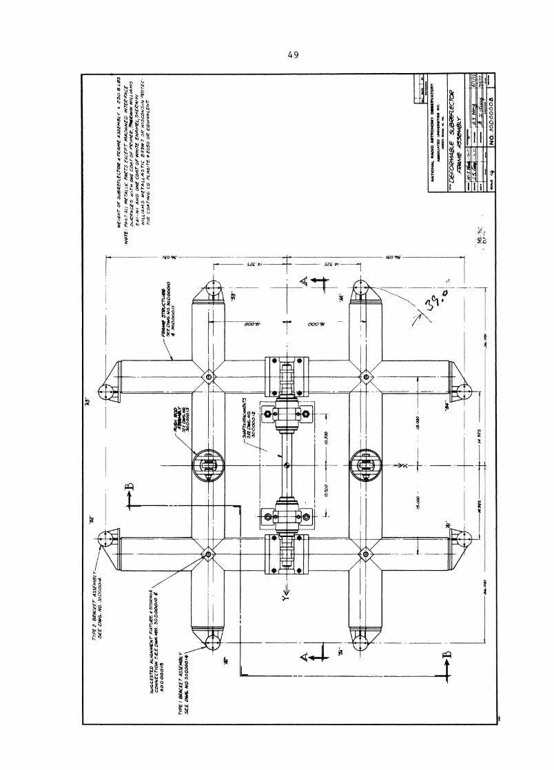
APPENDIX B
Engineering drawings of the Bakc-up Frame DWG No. 30 D 00008
to 30 D 00016.
:43"
TYPE
Z E
IRAC
rET
ASSE
meL
YSE
E 0W
6, N
O. 3
00000/4
suG
GE
5T
ED
.4
1.1
6N
mE
NT
FaT
uir
E‘
5T0/
ZA
6EC
ON
NE
CT
ION
5E
E D
W6A
105.
500
000/
0 0
30000015
TYP
E, I
MA
CtE
r AIW
A&
YSE
E D
W6.
NO
3oO
o00
/4
paa
me
JTA
PL
ICru
eeSE
e D
sVG
.Na
3000
0010
4 30
0000
11
1111
2111
11L1
11
II I
I
•
wE
1414
7- O
F su
BR
EFL
EC
TO
R F
rAM
E A
3.3E
Mal
y*
= 2
30
.8 z
85
NO
TE
: PAN
T A
LL m
ErAL
LIC
PAPT
.5 E
XCEP
T m
ACN/
NED
/NTE
R'A-
ACE
0uC
FAC
E5
WIT
H O
NE
CO
AT
OF
p,e
imf- ,e
,.016
triVi
N W
lLi/A
m15
Ea,
NI
AN
D O
NE
CO
AT
OF
4411
. 11TE
EN
AM
EL,5
NEZ
YW
NA
fiL
LI4
145
ME
TA
LL
5 T
/C 53w
7 a
e 4
1.44
5 G
OA/
5/A
i P'e
arE
e-
TiV
E C
OA
T/N
O C
O.
PLA51TE *
Z05
0 O
R' E
0wvA
LE
NT
NIM
MO
NS
1.4
NATIO
NAL R
AD
IO A
STRO
NO
MY O
SSERVATO
RY
AS
SO
CIA
TE
D U
NIV
ER
SIT
IES
IN
C.
GR
EE
N S
AM
. W
. V
A.
Dek
-oRm
AeL
E s
uake
Rec
roe
kle
AS
SE
MB
LY
. 051
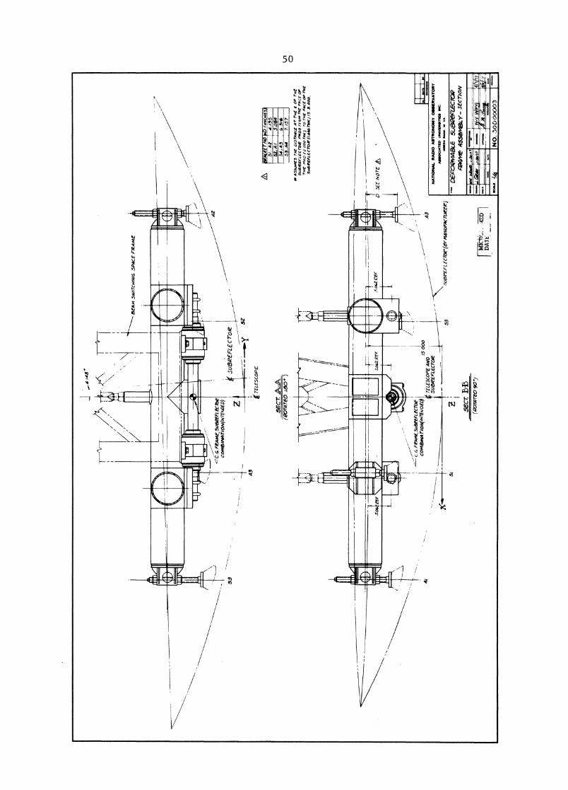
I0,
4.14
8°
BEA
M s
warm
/Am
5PA
CE
FR
AM
E
53
SUBR
EFLE
CToZ
42
- _ -
TELE
SCO
PE43
(PO
TA
TE
D 1
60
' )
-
C F
rAm
E,50
8CEF
LECT
Oie
CoM
EM
vA77
04/N
7Em
ota
L5 W
OTE
LE5C
OPE
AW
Dsu
ezE
rtec
roR
-
41
•rof i
rAtbe
1G
imr
011.•
NO
. 30D
0o003
5E
ct
AA
53
5013
1'E
FL fate (B
Y M
AN
UFA
CTI
ATR
)
AS3
uME
5 T
HE
Ln5
TA
NC
E A
T rfr
it f o
rm
r5
QaE
FL
EC
1D
•A
OS
FO
M 7
71( F
AC
E O
FT
we
OO
o T
M*)
ro
rs/E
FA
CE
OF
The
SIA
BIP
EA
L4c
roe
imp eo
rmo
Is 3
.000
.
D M
E N
OT
E it,
NA
TIO
NA
L RA
DIO
AST
RON
OM
Y O
SSER
VATO
RYA
SS
OC
IAT
ED
UM
VE
SS
IME
S I
ND
OM
EN
WA
NK
. W
. V
A.
51
2se
ct B
ib
Oparz
t reo 9
017
DA
TE
. ED
I
I— D
EA
- 04
4E
3a 5
(.1
13
42
EP
_C
-C7
01
?pa
g me
.45
se4
IBiy
- S
EC
T/O
N
scut
./4
L 1S
T O
F M
AMM
AL0C6Crr
a,Tio
NI1
IAA
RK
52 •
rAfif
i-S
CA
LIO
PfP
2' 6
.5.1
.14
ALLP
1 agog 3
.0..
.ff
36
.0
00
IA
AE 0
2/4
. illitt
63 I T
O
OVA
.
CSC I
.6
3SE 3
SO
LID
M41
2 Li
6T
tliE
IIN
SC
N40
PIP
E T
. AZ 4
67
...c
ezu
s.7
444wrli
K7w
.4.3
..54
a
/0P
AD
, /2rf
ruc.
2 Y
4 .
Z s
*
'Ira
12 Ira
MII
I
NO
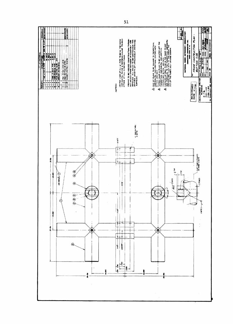
TE
.5:
C• N
TEE
LIN
ES
OF
ALL
4."
PIP
E 7
'0 S
E /A
I ME
SA
ME
NO
R/Z
oNTA
L P
LAN
E 0
PE
RP
EN
DIC
ULA
R T
O E
AC
HoT
hire
AT
A A
L 1N
reve
SE
CTI
ON
S.
PR
AM
E r
o O
E W
ELD
ED
Com
orieucrloa T
H210
0614
•O
UT U
NLE
SS 0
77.E
R M
ETH
OD
S O
FASS
EMBS
Y SE
ED
eriu
Leo
. A
LL W
ELD
S M
IN
F C
ON
TI/4
1610
0S F
Ole
eN
riee L
EN
dITN
DP
AM
AC
orm
itNT
(MA
TVim
ia)
MAP
FACE
S.
)11
06
1E
SM
OM
MIN
I•
=A
S W
INO
,
(AM
OrW
.Ife
rrie
5Pe
rirg
.O
MM
Atle
63
- .1
k0.
00 3
.015
0.00
11. t .
005
Orm
erse
.vs
Alt
AVO
WS
giC
RO
FIL
ME
DD
AT
E ar, •
1
A F
AcE
OF
PLU
GS
TO S
E SQ
UAR
E TO
rw
orencAL
HO
RIZ
ON
774L
AN
D v
Err
hcA
L C
EN
TV
EL
INE
SW
ITH
IN .0
05 I
NC
H.
- r- App
ED H
oLE
S PL
u65
TO
BE
LO
CA
TE
D o
r, T
NE
THED
EETI
CAL.
HO
RIZ
ON
TA
L A
ND
,VE
CT
ICA
LC
EN
TE
RL
INE
S W
ITH
IN .0
05 I
NC
H.
att
SIJ
EF
AC
ES
OF
A4
A5
M B
E I
N T
NE
s54
A4C
PL
AA
IEA
ND
PA
RA
LL
EL
712
TH
E r
utot
er/c
AL
war
/WA
/Du
CE
NT
ER
LIN
E F
LL
L5N
WIT
H T
o .0
50 A
BO
VE
TA
IE0.0
. o
r T
NE
TU
BE
S. O
NL
Y O
A IS
IOE
smos
eN.
NA
TIO
NA
L M
OM
AO
TIV
ON
ON
Y O
SSE
RV
AT
OR
Y40
100A
NID
• U
NN
INW
INII
MC
.W
OIN
IN W
OO
L W
. VA
.
FR
AM
E C
0N
57
RU
CT
/0N
PL
AN
-ao
rro
m s
iDE
4.
W.V
DIA
now
4 S
ET
S
PAO
41 4
TWX,
1 • x
54,4
GU
SSE
T' 3
/477
4K.r
inx.
511
Ie.
v.
=1
11 1L
-ai
m
t-g
.77
MO
NO
NO
. 3
00
00
01
0
/0
-17
. -<
4 S
ETS
-4
a -
A T
Y7?
-4 T
YP
3E73
SEE m
ore
&a s
ers
4 SZ
T3
--t
1+1
&up
f
Z.73
0 5.5
00
Thata
n__
___
_4.
375
Par
P440
1E3
AN
D L
isT
oFM
AT
EE
IAL
Sm
u i 0
11AS
. 8000012/0
a. V
O-2
0LIN
CZA
TH
EUa
PLA
CES
SEE
mir
nr
A9—
p f
>,
<251
73
MO
IR M
r
1111
1101
1111
1111
11
NA
TIO
NA
L I
MM
O A
•TT
ION
ON
Y G
OS
EN
VA
'TO
NT
AII
IMM
ATED
SW
WW
I O
WL W
. W
I.
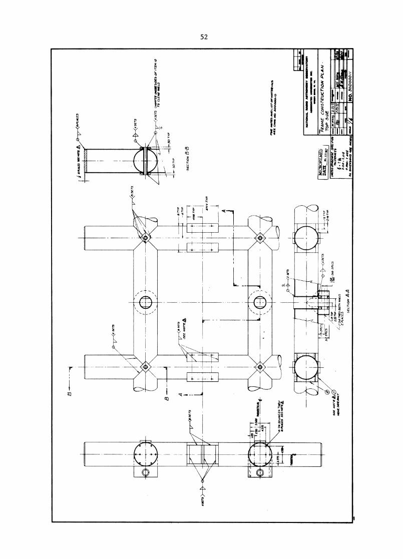
1.75
fPi
C5
3. ?P
ECS
,Yr
TYP
2,41
. TIP
FR
AM
E C
ON
6TeU
CT
ION
PLA
N -
TO
P 5
/DE
MIC
RO
FIL
MT
I)D
AT
E o
a
SE
E w
ort A,
I4EA
R S
IPE
ON
LY
LZP
1C5
TYP
Z257
VP
L2
.01
4 W
U B
OTH
WAL
LSPL
AC
ES
5 eC
T/O
N A
-A
5EC
rIO
N 8
-8
At
3/14
o. vro
33.7
.50 OC
EAK
698W
ER
tf37
3 itn
a11
370
—1.'
20 D
IA
F4
4.
1111
11.1
111.11
, /4E
PLA
Ce5
) 5.
?Co
2/' N
°1,7
5014
PL4C
ES)
IrEm
(:)
r04 M
ai
J3,4
5* B
OTH
CAM
6475
27
itA
D.
A."
Zt5
4315
41,3
0M
C-Z
4L,
. _1
L42
MV
O(7
NIK
O)
.1 M
K
4-4
0 T
h.,
1T
ris
IF n
iO .1
0ii
m3
770
1 3)
AIP
E P
fau/
4WD
E51
05 O
F I
, bo
o'
Or(
./4)
hysr
Nor
Plea
deC
T SE
YO
ND
SO
RP FA
CE O
F A
TM 2
a
'rem
®
a,r
,4572A
4aP
5)
/ 'P
P/X
S
4 ,
1/2,
9. rue.
* A
cib
iza 4
75D
IEP
/" 4
"gi
ro. m
ei 8
.4
ago-
jc.
firs
NAT
ION
AL M
OO
OSM
INIV
ATO
RY
AS
OIC
INIU
D u
nti8
801.
111
MIN
N M
K I
L V
A.
I. M
ICRO
FILM
EDD
ATE
0
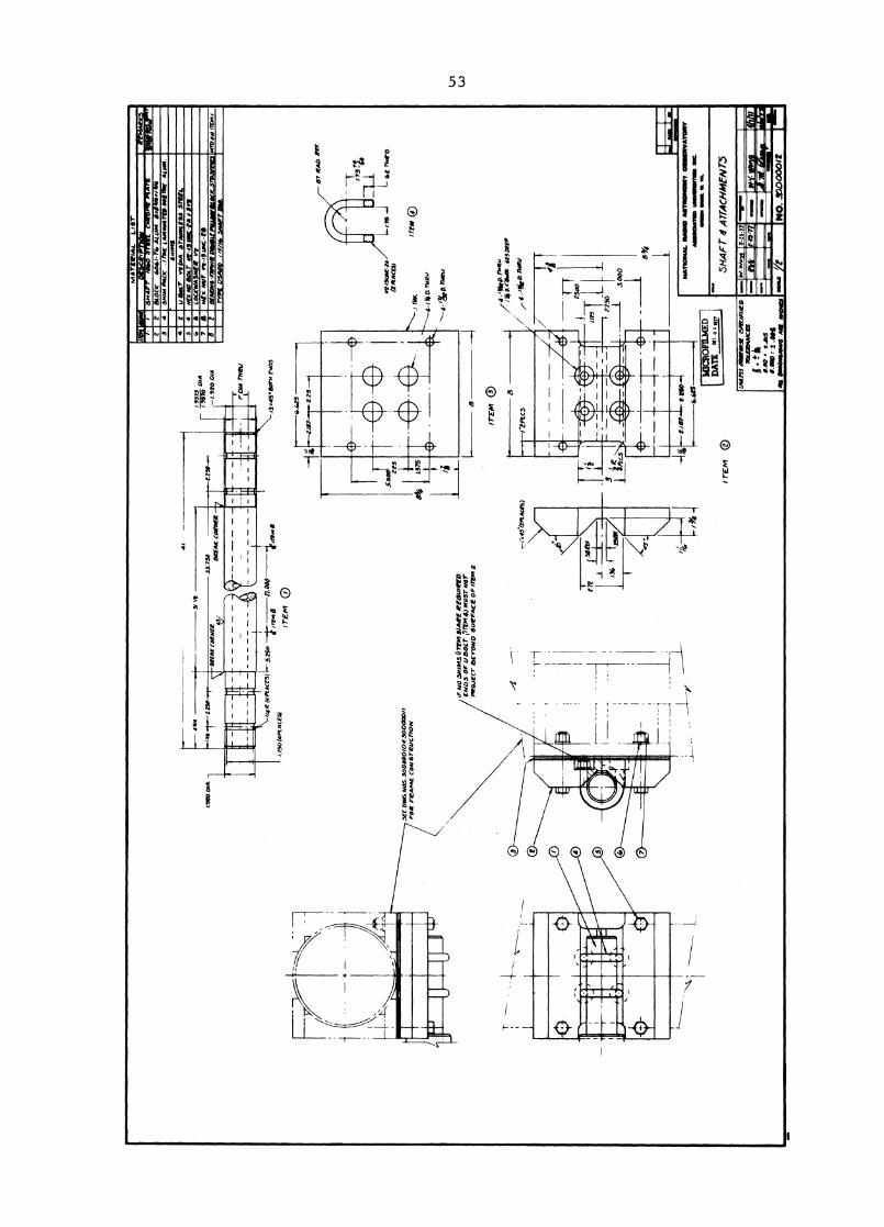
SH
AFT d
f ATTACH
MEN
73
LOO
M2” a
I—I N
4FLA
TSST
OCK
SIIE
4 1
US
ST
EE
L C
AR
ILL
OY
P.C
. 14a
0. I
1.07
LOM
E
ITEM
DE
UR
/PT
/ON
MA
TE
RIA
L L
IST
2M
APH
ERK
AL
ZN
IStIA
OE
SE
RIE
S,T
CE
LIN
ED
,PI
N V
VR
-14
z fl
3OR
5T
MR
t53
37
L I
NA
131
15.1
$
A 1
2.5.
3TE
EL
CA
RIL
LO
Y P
C. M
ED
AL
WA
SNE
R. /01
010.
X/1
0.0
. in/
GE
NII
S R
EO
LO
RE
D T
OA
CNIE
VE
A T
OT
AL
OF
.OTS
MA
X. C
LEA
RA
NC
EW
ITH
774
5 SP
HER
ICA
L B
ALL
11I
771
THE
NU
T
Z41
40 S
TE
EL
SN
AFT
IN6
1004
0.0.
15
CO
NS
Z.I
ISF
OE
t
,a Z
Net N
UT
1/4
INF
• E
a - S
ELF
-LO
CK
/MS
A.m
., 2 5
rAN
DA
IED
WA
SHER
FO
R .
/4 D
OL
T
AL
TE
RN
AT
E C
ON
ST
IVIX
TIO
N -
1I5
/N6
/4/4
Nfx
ST
A./
-L
ES
S S
TE
EL
IV
OD
AN
D /
/Env
? M
AL
E T
NIE
VA
DE
DP
RO
D E
ND
HA
IFx1
E -
/60
TH
RE
AD
ED
• A
WN
ED
IN
NE
V. R
OD
mA
IN774/N
/N6 1
3.5
7 0
151.
NO
MIN
AL
DIM
. .51
2E
PR
ESS
FIT
WI1
74 /rem
II'
I.00
rem
NATIO
NAL.
IMM
O A
STRO
NO
MY
OSS
ERVA
TORY
AN
DO
aM
um
as
IMP
. S
WIM
Vt.
VA
.
PU
SH
RO
D A
.536
4413
Lr
ME
SS O
INU
OIS
E S
PEC
IFIE
DTO
LERA
NCES
t. S
o t
415
0.0
00 7
4145
ALL
DR
IEN
SIO
NS
AR
V M
OO
"
OM
AFT
ER Y
EDIA
AIO
M.,
To D
EPR
ESS
FIT
ME
D.
MEW
PT
04 a
rm
s
tm r
TE
145
Se.
as5
DA
G N
O. r
im N
O 3
0000010
4000
0010
'rem
0FU
LL S
CALE
O1111
111111
111111
111111
111111
M3=
1111
1111
1rIf
h,Pr 5•
1:141
9111
1111
117/.
,
1,14
-ItU
NF-
36 4
-0E
EP .5
0 -
.-
ITEM
® 5
EE N
OTE .1
/.07
/3.3
7
15. I
I
314R
1.4
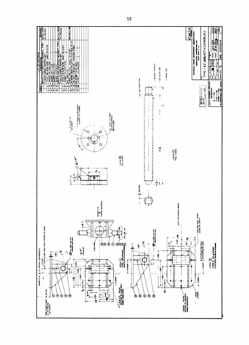
LIS
T O
F M
AT
EC
IAL
iTFA
IVIT
YD
ES
CR
IP
TIO
NBE
ACKE
T, F
t XE
D, L
O7S
OFF
SET,
NIZ
AW
Air
, TY
PErE
mA
RK
5W
ELD
A LL
P4I
TT5
2 J5
E0
A5
SPA
WN
, 212
oT87
ED
180
.L
L A
CO U
NE)
4 r
at
64
./5
5E
r V
4./
./ V
43 r
G, G
US
SE
T L
e4 r
3 v
4
C. 8
8
LO
CIC
2,3
1 /7 .4
arA
cKe- r
,Fix
ria,3
.o1
5o
rr5
1T
, W
ELD
MEA
lr , T
YPE
22
WO
AS
5NO
WW
,2 C
oTA
TE
D IS
O.
WEL
D A
LL M
IPS
ALL
AEo
LNJO
PL
AT
E 3
/SA
G6
S I
3.4
$ 4
04
/-7
4,
AL
IN,
GU
SS
ET
A.3
1'4
.5.Y
4.0
8 P
AD
30
1/3
I'L
G5C
EEW
rom
a Ir
L6
6,0
4, -T
at,
AL
UM
IIm
ArD
Ca4T
Ail
12 /
6,
5 r
4r
NE
A N
ur ‘,
8 U
NC
- 2 8
ST
AN
LE
SS
ST
EE
LM
EOW
Boa
YA
-TO
trA
iLa
88/5
88
1, 4 SP
LIT
_oL
cIN
ASH
ER
2PL
AT
E 3
48 1
13/4
.43 /11
TG■
Lum
.0
86,5
52
• V4
.5
, 41 r
r3
SET
PEW
SO
CC
ET N
O C
r., P
r A
rlo x
sr
01.01
09,1
NA
TIO
NA
L R
AM
O A
ILTR
ON
ON
Y 0
1118
1ER
VA
TOR
YA
SSO
CIA
IIID
LIN
N8R
IIM
MI I
NC
.01108 I
IA
MM
L W
. V
A.
TY
PE
I 1
Z 8
PA
CtE
r.455E
M5L
/E5
1111
.1111
11M
11.1
1011
1111
1.11
111.
1111
1:21
.11,
72W
an C
=II
ØM
CVW
ff
ME
Irr
y*fo
rmr.
Ty,
=m
a 00
.5.
2 D
IA T
NR
U
0 'N
W9W
W•1
•11•
1911
1119
1••
•
OU
P Il
l
NO
. 3
00
00
01
4
DA
TE
, „
9_9
U11
1E55
077
#EEP
OSE
SPE
CIFI
ED1T
AIE
RAA
KE5
A t V
at
0.0
00.
0410
.005
Add
DA
IIEN
SIO
NS
Aar
MIC
IES
neare
rica
t_O
F F
AM
E M
EN
I8E
le5(
8)
- .10
75 e
a
TUIS
E LE
N6
TN F
RA
M 5
.1.1
5, E
kfor
2 R
EFL
ECTO
E PA
O, A
ND
2 O
PPO
SITE
NA
ND
f or
FR
AM
EPL
ALE
5)
TN
. 0
60
,45°
°w
elt
row
eir
o5
-14A
45.
4 PL
AC
ES
OIA
418
0LA
.SP
OTP
AC
E lb
CL
EAR
KW
WH
EW
EM
ME
T°
7YPE
I Qu
atro/y
dsIT
EM
At,P
4S
EE
mule
44*
II T
-5.5
4.57
5
-38
25
I
?NA
LIE
S r
-20
uN
C-
r
- 4
- . /
. 3f O
M,
OA
/ 2.
000
LoC
AT
E A
, SH
OW
N
3,1 -
UA
W -
2A
TA
W,/
,..4
5•C
NA
N,F
ieM
TN
EN
DS
THED
REr
,AL
—4-
- -
-ar
4E M
ENIO
EPS
FiAD
1 TE
Ivi
FULL
.5CA
L E
X 4
5.
—T r8
,75
— 4
-0
roar
CN
A
-
45
. 5 P
LA
CE
.,
o-3/4
-
uN
F 2
8
//-r
--E
ttiN
C -
25
/ TE
MF
UL
L C
A L
E51
00 v
rEw
5Am
EA
S A
80vE
err
4oF
Z E
EFLE
c TO
E PA
DS
AND
2 O
PPO
5ill
.1.
NO
ITE
M 0
TY
PE Z
LoCA
TEIN
US41
,113
,52,
54,5
1RO
WV
11.3
s040
408
2 D
IA T
N2U
.510
2 Lo
cATE
SA
ME
AS
tTE
M /
..--3
.075
47.
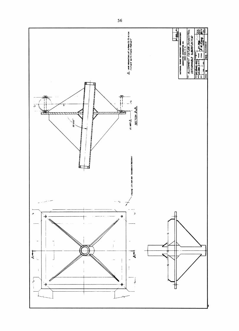
A :JI
MA
MOu
faiN
G AT
4I7
TO A
LIGN
f/A T
ukr
w,rn
FIX
ED T
ARGE
T-,
tt tor
t A
NA
TIO
NA
L. N
AM
AS
TR
ON
OM
Y 0
6111E
ITV
AT
OR
Y
MM
OC
IAT
ID I
MM
OM
MIT
IMI
MC
.
MIN
N M
s.
vra.
NO
. 300
0004
5
5Ern
oN
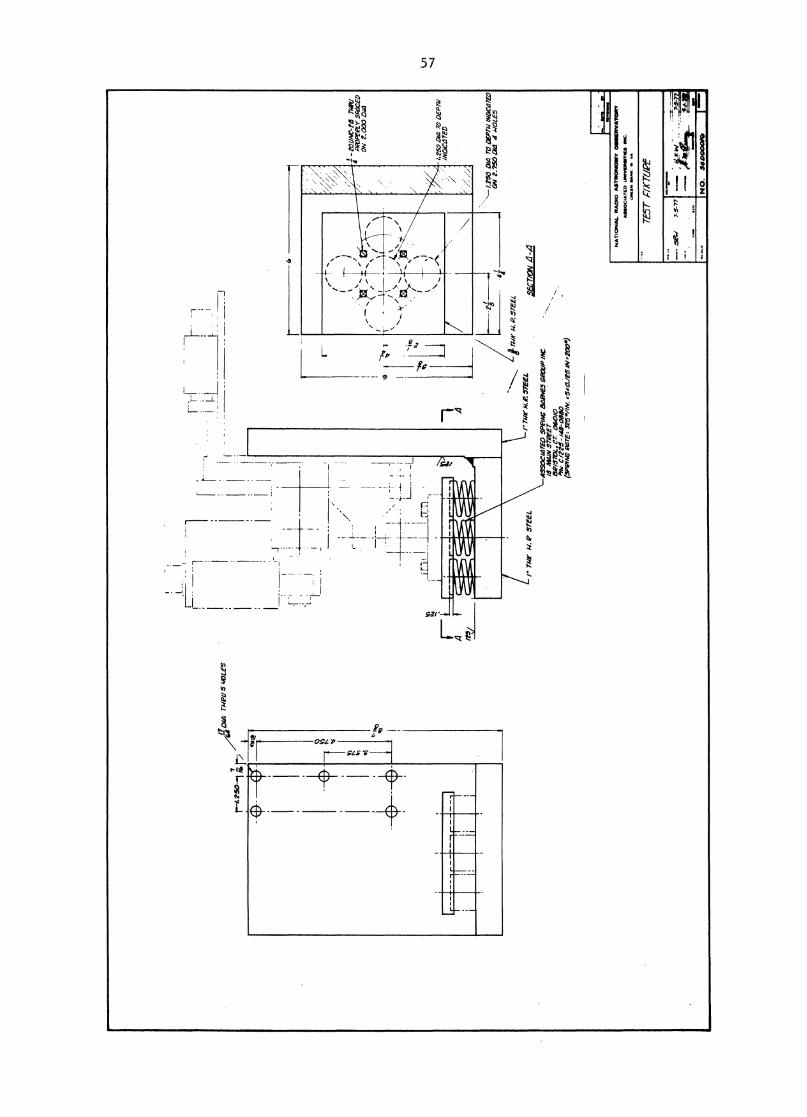
f-t
-
ti-770 I
I. ru
r m
P S
TE
EL
It
I
4- •
-I-
-
-1.1
50 O
ld T
O D
EPTA
I IN
DIC
:8W
ON
Z.7
50 O
M
weke5
N
W. A
' STE
EL
SE
CT
/ON
4-4
-/- ru
t- M
R S
TE
EL
- ZO
UN
C-M
mite
PPO
PEPL
Y S
AW
EDO
N 2
.000
DI4
4250
OW
re;
DEP
THIN
OC
OTE
D
/
•,
Tv
VW
n-r
-r--
•-
0/44
rw
ill
5 44
9LES
Z44
7N
254
-1
nr..1
.i
.
-1
i:
•i
! it..
._1
1c)
r--
-I
v, t. Ni
tks
ASS
OO
LDTE
D S
P N
C E
ZIPN
ES S
AW
A. /I
C/8
MA
W S
WE
ET
Cr 0
6010
*At
C i n
5 -
/411
-05,
00O
PPIN
G P
AT
E: 5
-25,
./IN
..5.-
0.11
151N
,200
.)
111.0
.00
3$
NA
TIO
NA
L R
AM
° A
STR
ON
OM
Y O
SSIM
INA
TO
RY
ASSO
C.A
TED
UO
NVIC
RIN
TIE
$
zatiri4 0
.41
1C
. IN
VA
TE
ST
ri X
TU
PE
•••-
• S
SW
7- 5-7
7
•ye
.
6,1
4
NO
. 50900016

58
APPENDIX C
Engineering Drawings of the Deforming System DWG No. 30 D 00017
to 30 D 00020.
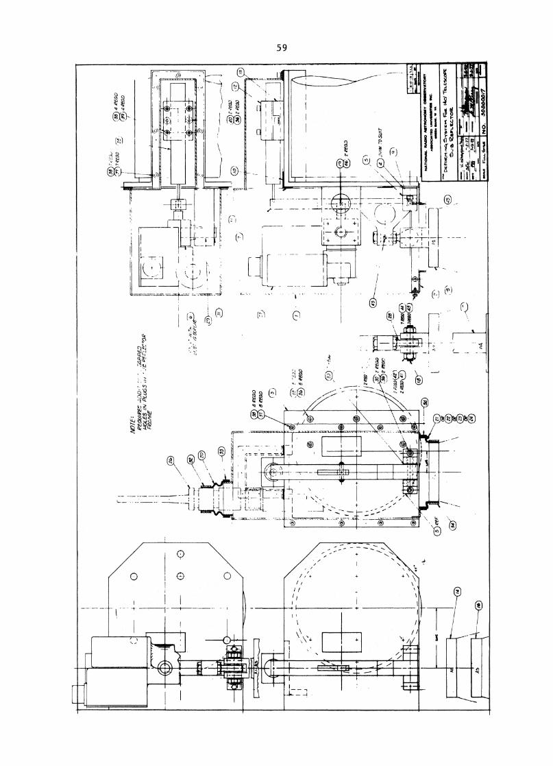
ef0D
3B 4
REG
O39)4
/MD
,—
ifN
OT
E1?
e011
/1?E
f_
:GPI
:3E
D1-
10L
ES
IN P
LU
GS
,/,/ _
ie B
EL
7LE
'.77D
RFR
ZN
IE
J
Fit
t
E_I
t/2
B P
EOD
8 M
D:7
)
( 3.-- i)
5 P
ew
\(1
;7)
-t-
46• P
EC
ID
: 21
)-
11
- -0
1
I
_-__
_ j
____ t*
rN
.1 i
I 1
II,
4 4
----\
i- 4111
-- 1
:11
- ..
....
42 I
NAT
ION
AL R
AIM
O A
STRO
NO
MY
OSS
ERVA
TORY
MIS
OCIA
TED
uNm
m K
.W
OW
W4
WW
W. W
VA
.
7.5.\
De
rocr
i S
ysT
E..
Fo
s. 1
4e,
TE
LE
SC
OP
E
o es
CLI
F.C
.TO
R.
r-a
•
ietz
-.1,7
11,
.11.•
A4.
▪fla
a...-
SvE
itN
o.
3000
0017
43
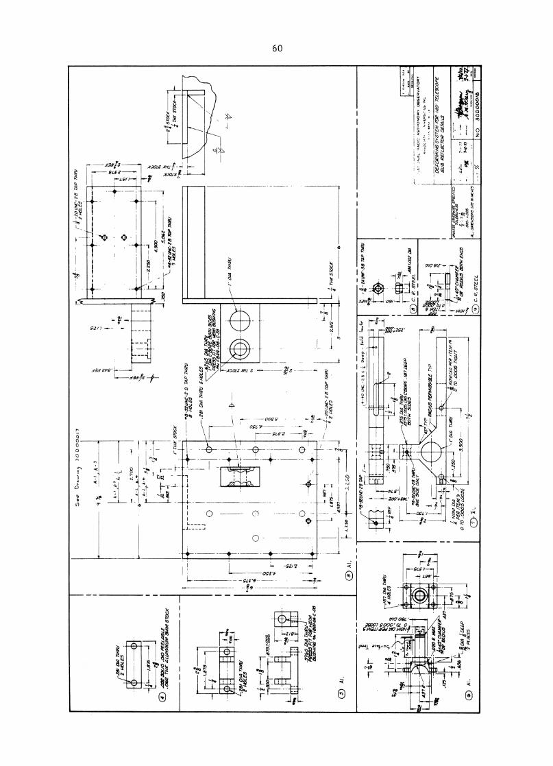
See
3 0
0 0
0 0
1 7
— -2
0 U
NC
-2S
TAP
TA/P
11,
2 110
LE..5
1
cr.; ' 2
wel
/ IN1 5-
2,5
TA
P 71
1211
rur
sro
cr
-- 2
.3I?
36
At.
T11
-4.,
.656
5 D h
a 1.
DEE
PPt
ACES
A-
A-
3
9
--Z
25
0--
- 4.50
D
—1 .7
50\—
.8-
521/
AC
-213
75P
MA
I/7
140L
E5
5.06
Z2:
STO
CK
THt s
rocr
1
rj-
— .8
-32I
/NC
-2 E
t T
AP
MN
./8
140L
ES
—
-
.626
5 D
IA T
A/0
1/0I
A C
'80P
E 80
71-1
5,D
ESPi
r5.5
FIT
AV
P M
OM
131
/SW
ING
Ii P
522-
08-C
-ES
1-
I" D
id 7
1.IP
L/
rI F
t))
1,4)
71
761-
-
,
alia
4.11
25_.]
..8-3
2UN
C-28
T4/
3:
111/1
1 PEF _ _
•,
.8-3
21MC
-28
THP1
/ON
E 5/
DE O
NLY
;I N
OM
0/4
PEP
/TEM
90
TO
.000
5 L
OO
SE
.375
4 TA
/PL/
4575
±.L
DIA
CZ3
OPE
.187
IXEP
BO
TH S
IDES
5.
TY
PP4
D/1
/5 P
E2M
125/
6ZE
TY
P
NO
IY1D
I4 P
ER
IT
EM
/9
0 T
O .0
005
7I6L
IT
ri--7
41IN
7-58
TAP
TIIP
IIot
o L e
mu
40.
4H
U 1 ST
EE
L0
C.
P.
.454
t 00
2 01
.4
.-,‘.5.1
— 4
—.3,
... -c.
,...-
2I
I 1
I O i .
147
- i
f!
f.45
. C
HAM
FER
OP
021.
2058
07- 11
END
S....
.,„.
® C
. P
. S
TE
EL
UNLE
SS on
aiiiw
ise. s
Pear
Lea
70/M
INCE
S-
.000, 4
00
0
isz, aw
n/sy
nc a
pe
5,2
11
1/5
1 1-1.7
.77 S
. " •
•O
AT
&
*in
••••
"1±
41
.
NO
. 3
00
00
01
6
v
.I87
DIA
WI/
4 HO
LES
4
At
*sa
x
171.4
4MFE
PoP
030
ILI3 4
37
-1.2
50
c# -
40 U
NC
-x 4
Dee 4-
-
,NA
L ,A
DC
AS
T.
ON
OP
AY
OB
SE
RV
AT
OR
Y
A,s
0C.,
,ER
S,E
S
DEF
OR
M/A
V S
YST
EM A
riP /4
0' T
ELES
CO
PE54
18 P
ECLE
CTO
P 0E
74/L
S
.281
DIA
THP
Z/2
MO
LES
0 .0
5250
L/D
.010
PEE
L.41
5LE
. 062
fl1
12LL
IMIN
LIM
SW
IM s
roar
A-
,,A
-36
ri_
2.70
0A
-L,
A-
4
A-
4-
I2
74
32—r
- 32
-.ea
.41"
TH
E ST
OCK
01,4
TW
O/
”
7-/
-77
ft'
7-C-
17
0
0 D t
P37-
1. 875
—4.
937
I.25o
i3.
250
;-]
r cs:
1.87
5—
Ito
,.."t=g
iss
riii
.376
0 DI
A TA
/PL/
PPE5
5 FI
T FO
P A/
E/M
81/5
74IN
G F1
30.0
4-C-0
8
quo
.150
07-2
L
q_
--■
•■■
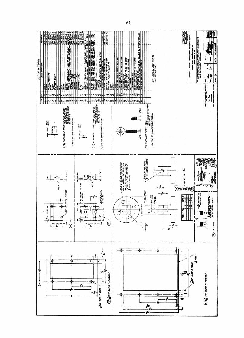
LIS
T O
F M
eiT
EPIA
LIT
EM
OTy
DESCPIP
TIO
NPE
/MW
CvE
PSE
E DE
TAIL
if._4
4220
- 7
.042
5 „am
p
-E1
3.3
75 P
•
,1410
(D
A L.
93 D
ia T
hipa
IUO
LES
1—.34
3
pup
c744
5E F
ram
l: BL
INTI
NC
Bar
eAN
D W
ait,
ZE C
OTO
L ED
o,aw
ia,43
i90
FL50
-84L
TEP
7r) O
wlE
tesic
ov si
zoN
A,
r-.r
5o1' .0
1r,
NE
M.3
75si
N
a D
IA M
EV
7 m
att
-I
—.2
81 0
14 W
UU
OLE
S
0
PUR
CW
ASE
reo
m IN
OTO
NG
seas:
"IN
D B
kriw
zE c
o.TO
LEDO
, OF1
10,4
3roc
kt, Y
A.e F
L205
- 3A
LTER
TO
DIM
EMSI
ON
540
WA
rN
aini
e2
04 Tu
t" a
uN41
-Al n
iaB
EP
--A
DD
4- '
51Y
4 1-1
0LE5
TI/E
LI
014
37-0
Cle
I" S
O. s
Tocr
Mos q
iuk
• •
Limos
DM
PER
/TEN
Ad
\
70 T
o .0
005
LOO
SE
lir-
./25
L .
266
0
PLIR
C44
56 row
NEl
lvl
PrIE
L 0
Cr 0
6430
isI
14M
-54L
TEA
' 7O
DIM
EAM
AD
A6.
9,42
0VN
an 5
4040
/ sV
ie O
vE A
l)6r
ie P
ECLE
CTO
P
1N
sAi
I\
\
5?-
\-i
cos
711V
MIL
ES \
TA*.
GIN
A"
A -
/co
‘i
-7
4 A
L
A -
2
_ 4
CriZta
wN
a SY
STEM
AN
D AM
' TEL
ESCo
PESP
LAS
REXL
ECtle
DEM
/LS
aNC-
1.4 S4
;-1
17
1'
Pi t
BOW
EN
D
Tw
r A
l-'
M140
1 "M
EP
ovuss
onvir
wee
SP
OO
PE
DIte
reV
IC
IS
.Cie
MA
. AM
.
avos
iosa
.0 4/
49E
04.4
..O
C..
L1ArD
4P6PLE
AV 11
(/
AP-5
.4s
A3. _
mos
Lam
e
1 =
1=
2
.:.
.......* it,
,, 1?,k1
4d
1 .t.
::::.
- — k
IR
t. c
..4
. ..-rz
t s, •
0 nit
retr..,.e
Abs
irD a
aae5
,i,
q z
oN 2
. • D
1.4
BC T
O /
/lATCH
MO
LES
IN 5
I8 P
EFLE
CTOp
41
INST
4LLA
7/0/
V S
POTA
AC
EI
Dal
ir P
EO
D
A 3
A-4
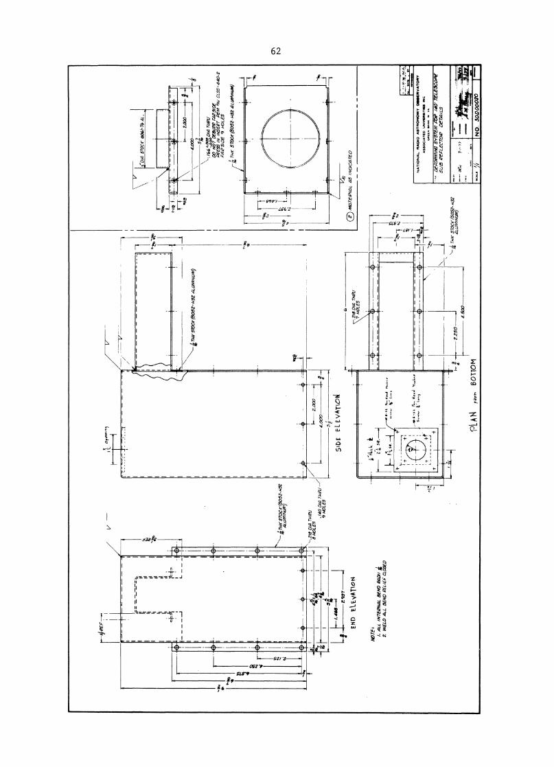
EN
D t
tEVATIo
t4.2
18 D
IA T
RP1J
7 HO
LES
•7,7
7
VO
pen.
ln,
J-:-
::-
::r
—
(K.
Sroc
rl5o5
2- W
.32
4LLI
M1NL
IM)
—.2
18 D
IA T
AIRI
8 HO
LES
.140
D14
WI/
9 HOL
ES
' 1-- 2
.0X)
G
4k :
1
514.
000
f-
LIH
468- 2
4 . 937
-
5;
SID
EE
- L
VA
TIO
4/
MZI
TEPI
4L 1
15 I
NDIC
A7E0
NO
TE
%
I. A
LL 1
NTEP
NAL
BEND
RAD
// g
?. W
ELD
ALL
BEND
REL
IEF
CLO
SED
\
,..1-
111 ..
.5_•!
.`,
-;
5TOC
e(50
52- W
32—
ALU
MIN
UM
)2.
250
4.50
0
PU
NA F
BOTT
OM
•
NO
. 30D
00020
V'D
I4 s
rocr
604
1-T6
4C,
2.00
04.
000
- f .: 0T3 0 D
al W
VDO
NOT
DEB
UPP
F4P3
10E
PeES
S /A
/ IA
/SEP
T PE
MP /A
/ CL
55-4
40-2
CAP
SID
E 9
HOLE
S
Tur S
7DCr
(505
2-I4
32.4
LaM
m/l/
M)
•
NA
TIO
NA
L R
AD
IO A
ST
RO
NO
MY
01
16
ER
VA
TO
RY
AS
SO
CIA
TE
D U
NIV
INS
ITII
ES
IN
C
Gre
ttiv
Sao
. V
I V
A
•D
ECO
PM/A
G S
YSTE
M R
AP /
40' T
ELEW
ORE
SUB
k'EF
LECT
.00?
Of 74
/L5
1 ry
e ST
OCe(
50.5
2-1/
52 4
41./M
INLI
M)

63
APPENDIX D
Engineering Drawings of the Measuring Jig and the Gentry DWG No.
37 D 00002 to 37 D 00007.
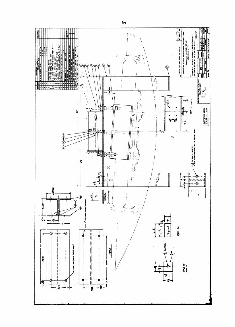
x x 4r
-4-
S Ar
t4 5
rEfl
_ A
MD
El 111
1II
I5-
2van!
8.1
4m1.
533x
4SIP
Mr3
r8 a
rm T
E x
2'-2
G,
r-S
UN
L-2 5
7- EfL
HEX
MIT
Ii : . ....
ZTEE
L F
LAT
w.W
A-Sf
lerv
...
ER ...
,z. t
r L-7
- 5
iv,
II1
4* x
asit
xi S
TEEL.
PLA
TE A
36K
"
1:: 1
:1-2
: rEi. TAD
D
ED
RO
D .
i P
M 3
PIER
ICA
L P4
t5ili
efO
ltr IA
NE4
a-,,,
W)
Ivo-
KW
IC S
TEEL
. HEX
Nur
‘,..
it LIN
C -Z
A X
/0 5
TEELT
NEEAD
ED
ED
i i
3%
1 %
4 sTeel
.. A
t44
LE
L. V
. 1..4
Iti
0`-,,, 2
:0 .
...
war.
, vro
,s,
0 0 0 0 0 0
AI
52
4-
l" D
IA T
OC
IJB
OW
414 P
CII
NG
E
mA
"grt
oih
g.
FASE
VATE
D ST
EEL
LIE4
144/
4.1
,2i
ST
EE
L P
LA
TE
A34
TrP
or-4
5E73
LOCATE
,01
1.00
1T/O
A/
801(
.73
ProP
, A
ssr
SU
PP
OR
T , M
EA
WR
INI6
- D
EFO
RM
AB
LE.
Co4Y
eR.E
vL
e.cr
ore
* F
RA
ME
A5Y
501
of e
- ----
-4--
- •
----
--.)
- r,
;
0 cr
ok.i
pet
.volt
.*
NA
M:W
M. R
AW
. A9r
rose
104.
1y o
efit
itV
AT
egy
me*
. Are
* V
.Vir
atio
ntS
elell
ie O
.K.. 4
,
mic
Ro
nu
iED
DA
TE
zt 1
,71
W/L
E55
OTI
EEW
ISE
SPIX
ORE
DT
AC
E44A
/CE
5
I o.c.
2
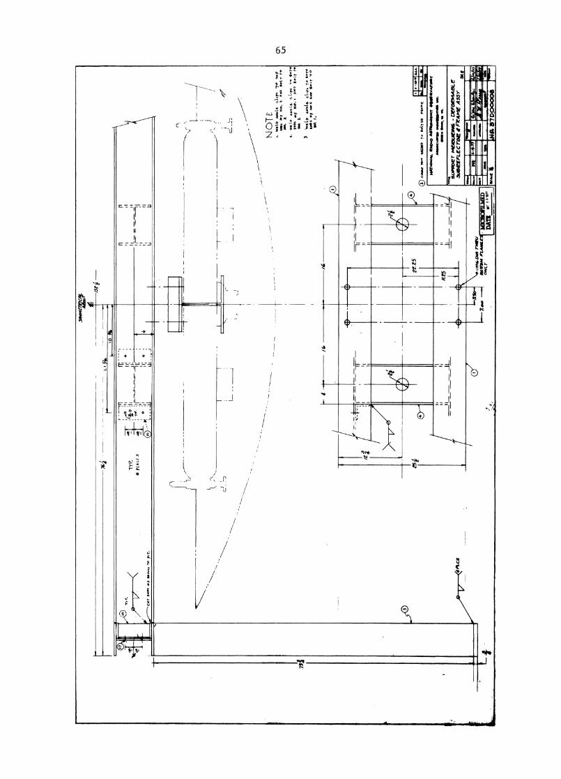
_
,DPI
ML7
E7CA
L*
awl'
t
t
TY
?.
0 P
LA
LE
rflT
irE
•-
0
r
_
•"1-
7.o
.-M
AL o
ho T
AW
)00
~ 1
, LAMI
mic
ao
mm
ED
YD
MZ
"
*17
NJ
E,.
%ve
to m
icit
CAW
ST
epM
s A
sp N
o.
3 A
. .1
. T
1. fi
kp o
ttip
Aw
sig
. cli
ps
Te 1
P•T.
RO
Ms
of M
o. •
1.
0
geI
T r.
N.
2.
3 W
EL
Dcl
irs
T. S
•i.
ism
s •
f .d
.4 A
sep-r
WO
. ,
S
4 P
'LCS
—
11
rt25
0 c.
a.!
p ar. m
aw
, T
. •N
4,1.
IMIK
aso A
1111
1bme
solY
4141
1611
111tv
Aras
yA
sseesa
vap w
avel
leoo
m o
w-
Soso
111
/jff
5
"IS
UP
PO
le T
Mel
leU
ZV
AS
DE
FOrM
AIK
3tA
l5C
EFL
E C
roe
t Fr
Am
e 45
5YSt
tSA
Lc
c Gook M
I
I'
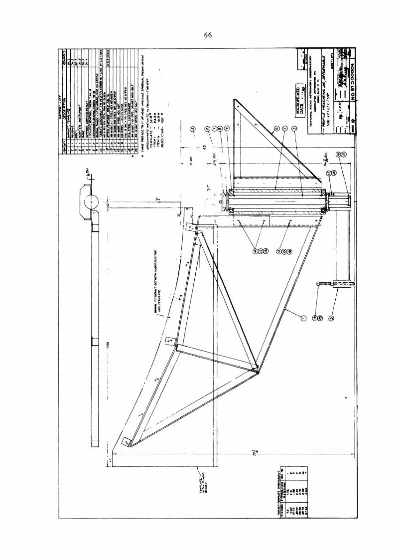
e2 _
8
\
Sit
Z34
. 3sv
. 3
5N. 4
mi.
3
ittM
42V
CS
•54
,0PO
LT C
OO
N T
EZW
EI6N
T
7LO
CZN
U7,
1212
111G
, TW
OC
EN T
AN-i
s LO
CCnow
t TW
Nana, ra
mro
d c
oPm
s636
30_,C
ON
E m
a 65334
7- 4111
5e7
4i.I&
NM
ENT *
TO
M *
Mar
AS
,I,L
ito
I/fr
4-4
e. 3/
4P
aill 0
01
42.1
011
PL
OM
Illa
V/2
/2
13N
o-m
uNci
ii. S
TE
EL
NO
419
30tE
w
/4-v
s-4,
11K
M*
SOEE
L M
SC N
D S
cler
a,
1514
1-46
SOC
NS
STE
EL
cO
CK
WA
SH
EC
/7 1
5/44
-ilt
uNC
IN
EM N
DSO
PEV
I 1
2 I ?b
sr=
Locrw
Asie
rg
fs 3
Sv
-ii
MC
11
0 s
rra 3
4002
C N
OW
SK
r C
O 3
444
0 M
C 5
72E
t N
ix N
ur
•CN
A-Se
75e
'EAD
5 TO
OF
ii240
ilACIN
NE
SPN
SVIC
At
riha
vs O
N EN
D.
TEM
PLAT
E.'I
d T
N. P
LY
WO
OD
SACK
ED
F •
FOR
eff-T
EMPU
ITE
DIM
ENSI
ONS
ed..
/P,N
at1 N
I
7.0
'I.
7*1
1763
19!
eV
tSi.
t.3
31.0
0CA
S4
49.3
0rill
552
.75
*7.t
5_
2.5
a260
4. 7i
MIC
RO
FILM
EDD
an,
PtA
lialw
At.
RA
MO
AST
UO
ING
WV
Gal
laaV
AT
IOR
YN
osat
eNT
UP
tow
vaR
aVel
law
ww
w Io
wa.
w
NO
. 67
0000
04sort
t fi
f4 MEM
O
41 lC
Lfft
Z*N
tE 1
3(71
42EN
Sud
errt
rert
ie400 r
einet
Art
*WV
.1M
AT
( w
EiG
H73
PoO
N1r
3 -
FOR
IZ
2FTE
*101
.472
- 2.5
*TE
Nt
-
23.3
*IT
EM-
6.9
RCO
D 0
4i-
100 *
1
FIL
E m
EA5U
LIN
6 JA
S, Z
IEFO
Z74A
BLE'
SUB
- Er F
LEC
TOle
7241
3,4.
4
GS. S
ToCK
G.O
. 5To
Ct
72'.5
8
f
X
49
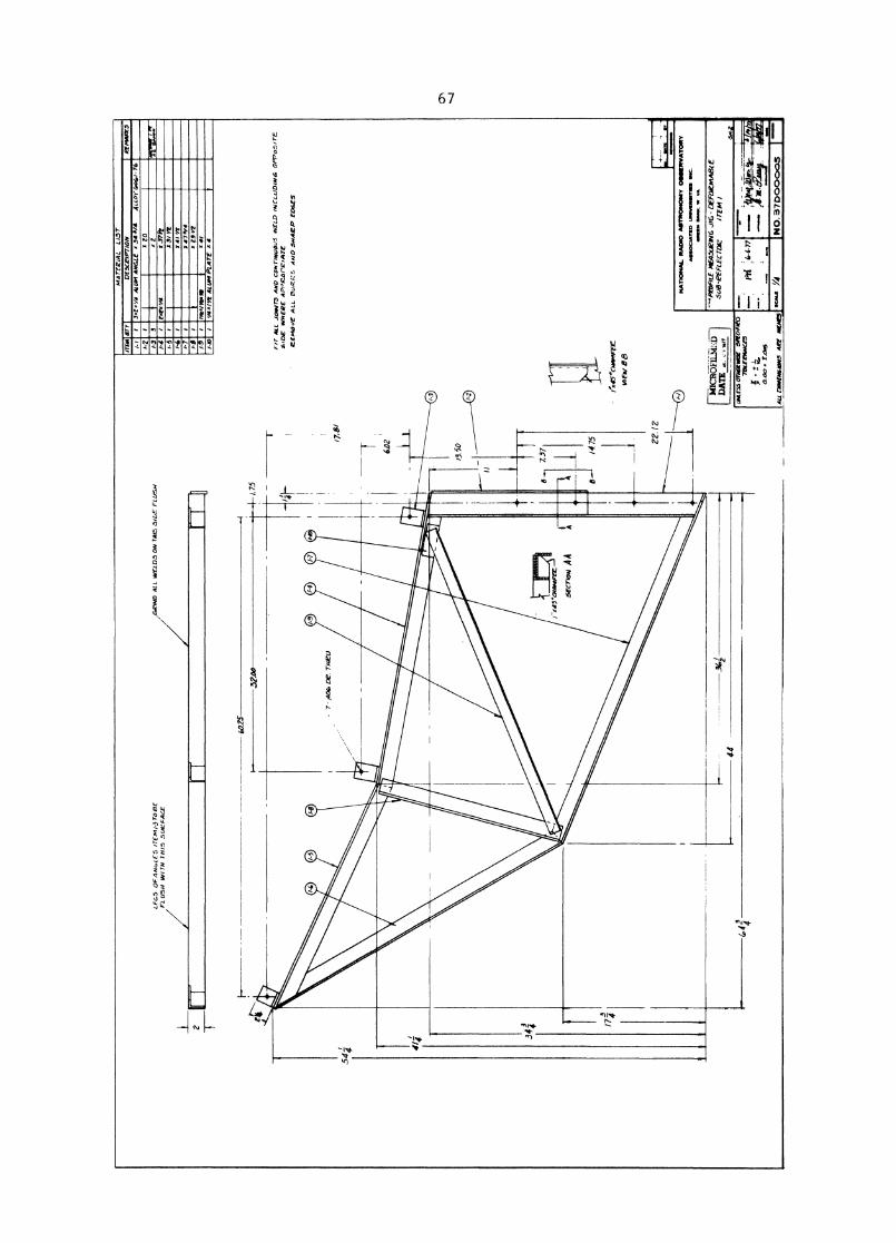
•Vi•
.1.1
11.4
111,
A11
1. ..1
•1*
MA
TE
RIA
L L
IST
ITEM
ID'
DES
CR
IPTI
ON
REM
ARK
/-1Y
A A
LUM
AN
GLE
34./
4A
LL
or
6.4
,/ -
61-
2I
LOL
FC-,
5 O
FAN
L,L
E5
ITE
M/J
.1-0
8EA
LL W
ELD
S O
N T
N 6 .5
IbE
FL
USH
/GR
IND
1-3
3Ii
7iN
ewom
r rc
FL U
5H W
ITH
7P1
15 5
UIe
#44C
E/-
4.T
.1/4
1I
37I
/-I
3/
Yr
-614
1 Y
r1-
7I
47./
4X
ZS
YE
/-9to
k./9
MIO
.41
/40
*/4.
/ A A
L10
1 PL
AT
E I
60.2
5
F/T
AL
L J
oaV
T5
AN
D C
ON
TIN
UO
US
WE
LD
MIC
LOD
IN6
OP
PoS
ITE
SID
E IN
HE
RE
APP
. R.a
rk 'A
TEle
EM
OvE
ALL
OU
RI,.
. AM
C. .5
,44Z
P E
D4E
5
II,45
4101
4mA
TRII
,EW
Be
altm
eani
NA
TIO
NA
L R
AD
IO A
STR
ON
OM
Y O
SSE
RV
AT
OR
YAS
SOCI
ATIE
D U
NN
IEN
INTN
II I
NC,
SO
W*
N.M
. IN
V.
•■••
••••
—. PA
W/L
E M
EASU
RIN
G JI
G- D
EFO
RMA
BLE
508-
E.EF
LEC
roe
ITE
M/
All
rin
ato
sio
N5 A
RE
IAK
NE5
p40
_ 37
D00
005
4
r
ikIC
RO
FIL
ME
D I
DA
TE
[ME
W m
oms(
SPE
CIFI
ED7
ERA
NLE
S
= ary t.
ors
ed 6
-6-7
7
;
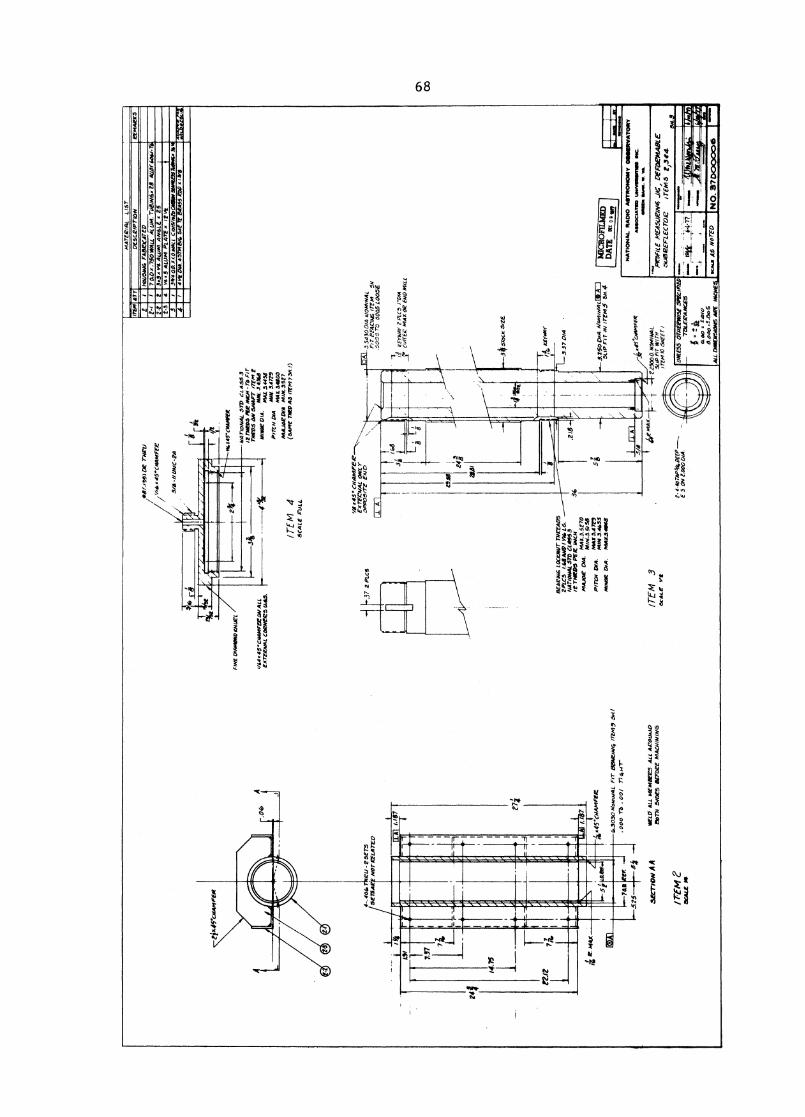
MA
TE
RIA
L L
IST
TEM
AT
2I
2.4
Z-Z
2. 3 4
DE
SCR
IPT
ION
HO
OSIA
I4 F
ABRIC
ATED
50 A
.750
WA
LL
AL
L)M
.TiI
BIN
6;28
*to
r go
ta
34'4
02 X
1.0
WA
LL C
ioi5
/isZo
CA
SW S
tAII
IESS
NA
WS:
361
4Pt
CM
. 43T
NSK
54(
72 8
1EA
5S R
OD
WS
6.1
9co
mo
wea
I4N
.r45.
CHA
MFE
R
/7(M
4SC
AL
E C
UL
L
NA
Tio
NA
L 3
772
CL
ASS
.3IR
TW
OS
PER
AW
N -7
7, F
ITT
iiRD
S O
N S
HA
FT /T
EA
, Z.
MIN
3.0
68M
INOR
DIA
. MA
X a
uss
par'
, D
M "
UV 547"
MA
X. 3
4103
MA
JOR
IN
A M
IN.1
527
(SA
ME
TD
45
iTfA
l 7 S
N. I
)
k37
2 PL
CS
L54
3001
WO
AN
NA
LFi
T PE
XC
IAIS
ire
m...w
oo
7'0
000
5 L
OO
SE
tit
737
1.1
67
8EA
RIN
6 LO
CK
NU
T TH
RZ4
D5
2PL
C5
ht.B
AN
D I
Wir
LS.
NA
TIO
NA
L ST
D C
1AP9
53it
TW
OS
PE
R I
NC
Hm
AA
,e L
AM
AX
.3•5
"°PA
IN.3
.SiS
Sm
oor 5.
4in
MIN
3.4
655
MA
X.S
4018
PITC
AI D
IA.
MA
NO
R D
IA.
4,30
30 N
omm
iAL
5B4R
AN
4 IT
EM
, 544
.1. 000 r
b . 0
01 7
7 4
1-e
rN
AT
ION
AL
RA
MO
AST
RO
NO
MY
OSS
OM
VA
TO
RY
ASS
OC
IAT
NO
UN
IVIE
NIN
TN
NI
INC
.G
OW
N N
UM
. Vo.
vA
.
WE
LD
AL
L M
EM
ER
T-5
AL
L A
1:W
.0774 5
IDES e
rnee
MA
CH
ININ
G1TEM
3se
AL
E:5)02EFLECTO
Z irem
s
/rEM
eS
OM
E M
t
I NK
S A
S N
ora'
NO
. 37000006
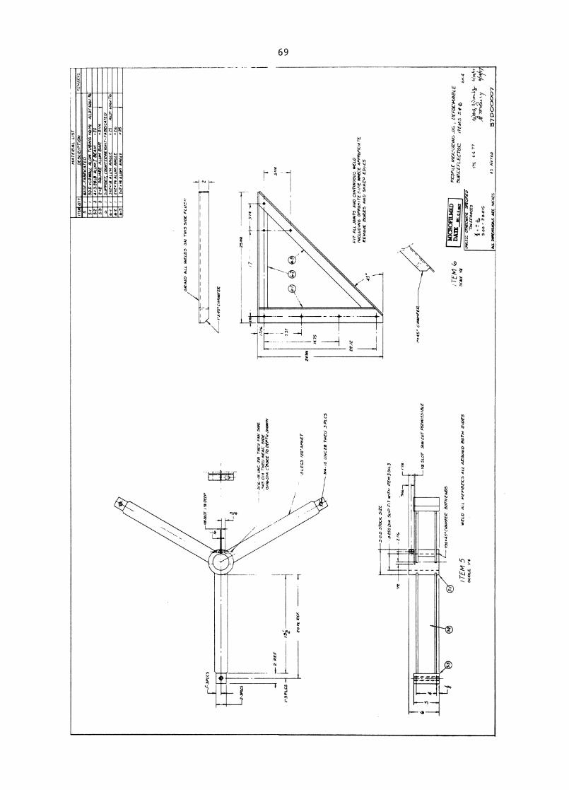
ITE
M 5
SCRLE
V4
WEL
D A
LL m
FmES
ECS
ALL
AZ01
1141
0 BO
TH 5
/DF
5
- 3//
b
UN
C-Z
B T
WO
FAA
' SID
E.3
4.3
DIA
rneu N
EAk.
510
5i3
f. D
/A c
'e30
eE 7
5 DE
PTH
-SHO
WN
LEG
S /
20
' AP
Aer
.314
- /
0 UN
C Z
8 TH
E' U
3PL
C5
500
STO
CK S
IZE
3250
014
5Li
P FI
T W
ITH
ITE
M 3
31,3
2.'é
r LyR 5
LOT
54AI
CU
T PE
RM
/551
&E
V32
.45.
0MM
FER B
OTH
EN
DS
253/
4
3'./
4 - s-i
--rf
st
rt.
I
7.37
.75
22.a
/ 7
- -
-
5,1
4
Z44.
4
FIT
ALL
JOIN
TS A
ND
CO
NTI
NU
O/D
: W
ELD
INCLU
DIN
G O
PPO
SITE
SID
E W
HEC
E AP
PRoP
C/A
rECEM
oVE B
OERS A
ND
SH
AL7
P ED
E5
45 •
1. x45
. CH
AM
FER
ITE
M54
15 2
4
PC'O
F ILE
MC
A:W
e/N
G J
IG ,
PEFO
CAIA
EL
E51
.1 aCEF
LECT
OC
/TE
A45 5
f,2,
4uN
LE
5, O
T1I
ErW
I5E
,5
0F
orif
p
Tot W
ANCE
.5
0.0
0 1
'0.0
15
1; 14, 64.
77
A V
- 03,
0,17
7
37C
, 00
00
745
Wor
e,AL
L DI
MEN
SION
S 42
2 IN
CHES
MATE
IZIA
L LI
ST
STY
DES
-CS/
PT/O
N,I
MAC
K5S4
5E-F
ABRI
CATE
D50
.0.1
1.0W
4LL
ALU
M.T
/D1N
6V
zAL
LOY
606
1-T6
,34r
3.21
ILB
ALU
M I
BEA
M.2
03
212
5QU
ACE
ALU
M B
AR
5V4
ITEM 5 5-/
5-2
5-3
SU
PP
OE
T; C
OLI
NTE
KW
EIG
HT-
FAB
CIC
ATE
D6-/
3x2,
4 A
Lum
AN
GL
E%2
/ ALL
OY
606/
4-6
21
r. Y
4 AL
UM
AN
GLE
.2‘
6-3
2.2
.4 A
LUM
AN
GLE
35
5R5J0
ALL
WELD
S O
N T
H/5
5/0
5 F
L,5,
5\
i,
rx45
•CH
AM
FE
K
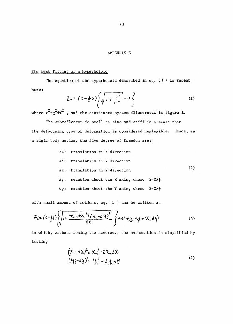
(c--10t)2 (1)
70
APPENDIX E
The equation of the hyperboloid described in eq. (i) is repeat
here:
where r2= x2
+Y2 , and the coordinate system illustrated in figure 1.
The subreflector is small in size and stiff in a sense that
the defocusing type of deformation is considered neglegible. Hence, as
a rigid body motion, the five degree of freedom are:
AX: translation in X direction
AY: translation in Y direction
AZ: translation in Z direction (2)
A(I): rotation about the X axis, where Z=YA(1)
A*: rotation about the Y axis, where Z=XA1P
with small amount of motions, eq. (1 ) can be written as:
in which, without losing the accuracy, the mathematics is simplified by
letting
(7, X) 1 X,4 * -
-4 E)Z
2-(4)
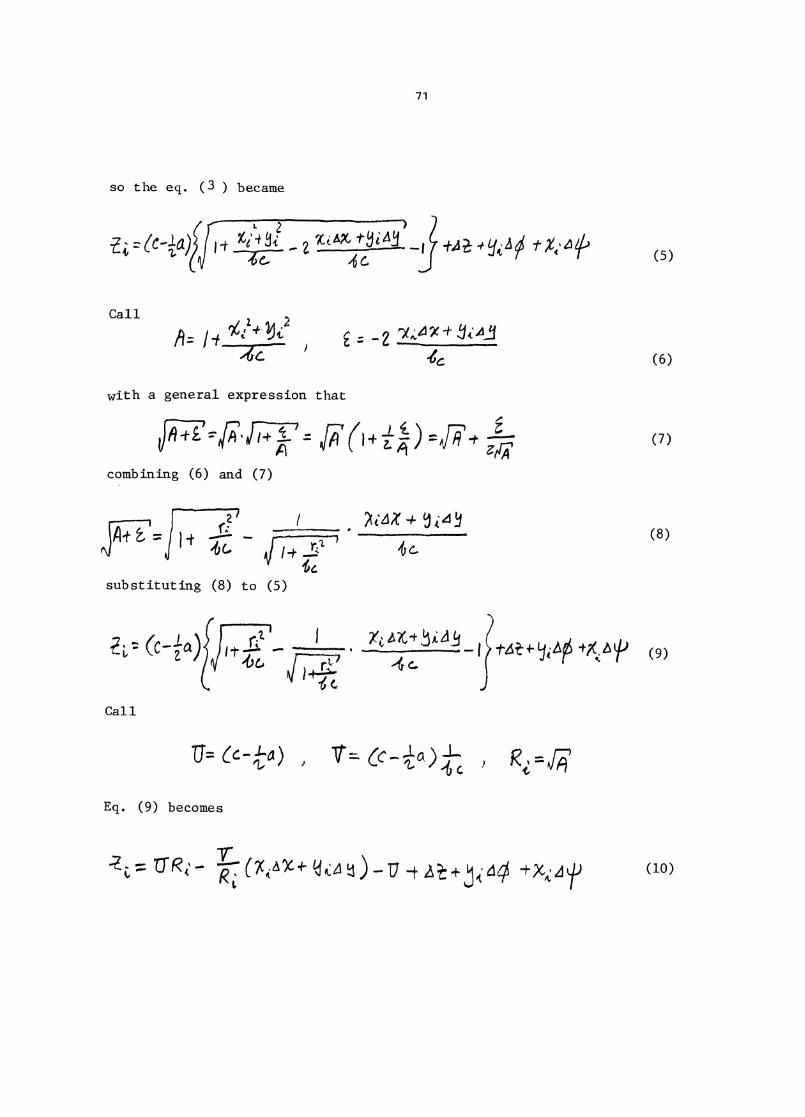
(7)
2q4X 4
substituting (8) to (5)
1-46- +X, IP (9)
so the eq. ( 3 ) became
71
1..t. 76'4 ‘ 9c,sf."(d.t- i,e13- —
/6C"IP,Q• 'Y4, A 9S %4%14') (5)
Call
A = 1 .4c.—
with a general expression that
-2 7A#49c+(6)
combining (6) and (7)
(8)
Call
17= Cc-ta ) I V' cEq. (9) becomes
7 tA,c + 140,:4 (4) —17 (10)
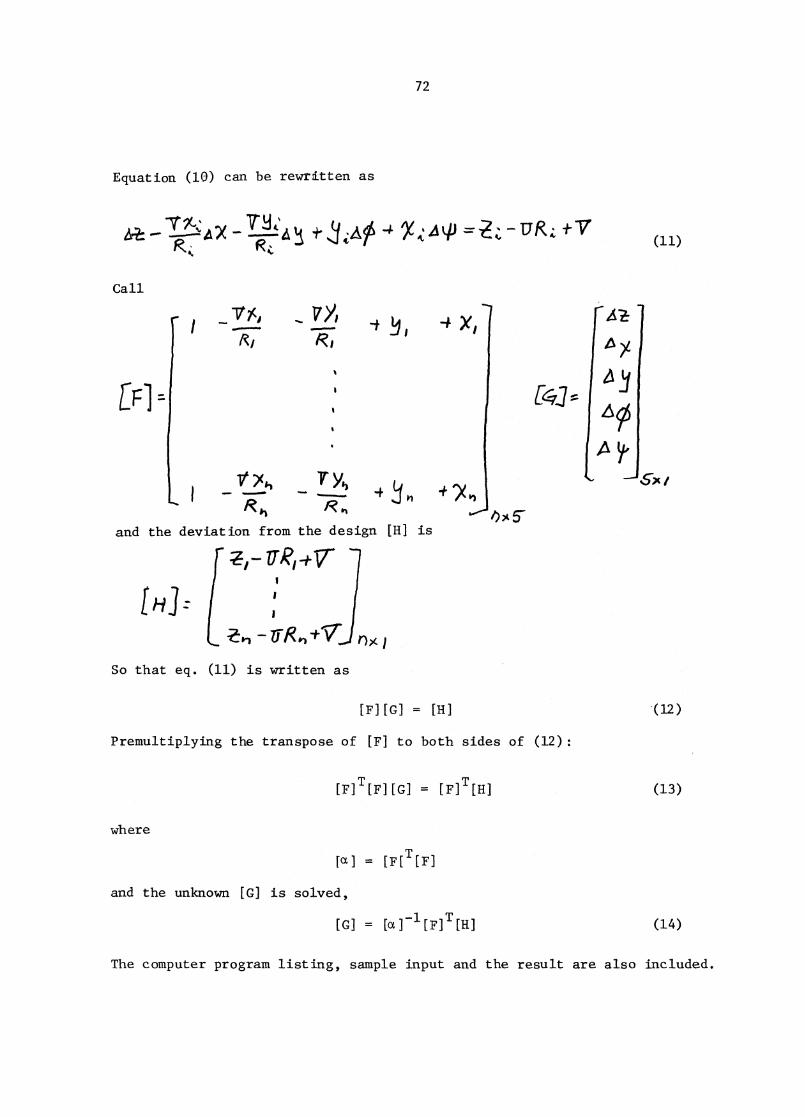
EFI
6"-x/
Equation (10) can be rewritten as
72
1M(‘A *14-‘ 4 4' uRez v
Call
and the deviation from the design [H] is
So that eq. (11) is written as
11x
[F][G] = [H] (12)
Premultiplying the transpose of [F] to both sides of (12):
T
[F][G] = [F (13)
where
fet
and the unknown [G] is solved,
[G] = [ct [F] [11] (14)
The computer program listing, sample input and the result are also included.
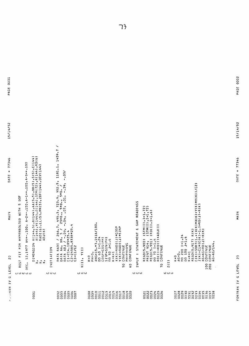
t.-%1RAN IV G LEVEL 20
MAI1
DA
TE
= 7
73
46
15
/14
/52
PA
GE
000
1
C BEST FIT FOR HYPERBOLOID WITH 5 DOF
C DEC. 12,1977 A4=-.100, A-2=-.100,A-1=+.100,A-3=+.100
0001
DIMENSION A(144,5),B(144),AA(5,5),B8(5),S(5),C(144)
X,
X(144),Y(144),1(144),STM(72),R(144),R0(6)
X,
RA
DI(
6),
LL
(5),
MM
(5),
LB
F(1
44
),D
EV
(14
4)
X,
AD
J(6
)
CIN
ITIA
TIO
N
0002
DATA RADI / 266.7, 4
95
.3,
72
3.9
, 9
52
.5,
11
81
.1,
14
09
.7 /
0003
DATA AA, BB, S / 25*0., 5*0., 5*0. /
0004
DATA ADJ / -.09, -.04, .07, .01, -.09, -.031
0005
C1=214.185*25.4
0006
C2=24585.8338*25.4
0007
C3=C1/C2
CX(I), Y(I)
0008
K=0
0009
PH=0.
0010
ANG=15.*3.14161180.
0011
DO 60 1=1,24
0012
COSP=COS(PH)
0013
SINP=SIN(PH)
0014
00 50 J=1,6
0015
K=K+1
0016
X(K)=RADIIJI*COSP
0017
Y(K)=RADIIJ)*SINP
0018
50 CONTINUE
0019
PH=PH+ANG
0020
60 CONTINUE
C INPUT : STATEMENT C GAP READINGS
0021
READ(5,900) (STM(I),I=1,72)
0022
PRINT 914,
(STM(I)11=1,72)
0023
READ(5,901) (R0(I),I=1,6)
0024
DO 70 1=1,6
0025
R0(1)=R0(I)+ADJ(I)
0026
70 CONTINUE
C1(1)
0027
K=0
0028
AG=0.
0029
DO 200 1=1,24
0030
DO 100 J=1,6
0031
K=K+1
0032
READ(5,917) R(K)
0033
C(K)=SORTI1.+IXIKI*X(K)+Y(K)*Y(K))/C2)
0034
Z(K)=C1*(C(K)-1.)+R0(J)-R(K)
0035
AG=AG4RO(J)-R(K)
0036
100 CONTINUE
0037
200 CONTINUE
0038
AG=AG/144.
FORTRAN IV G LEVEL 20
MAIN
DATE = 77345
15114152
PAGE 0002
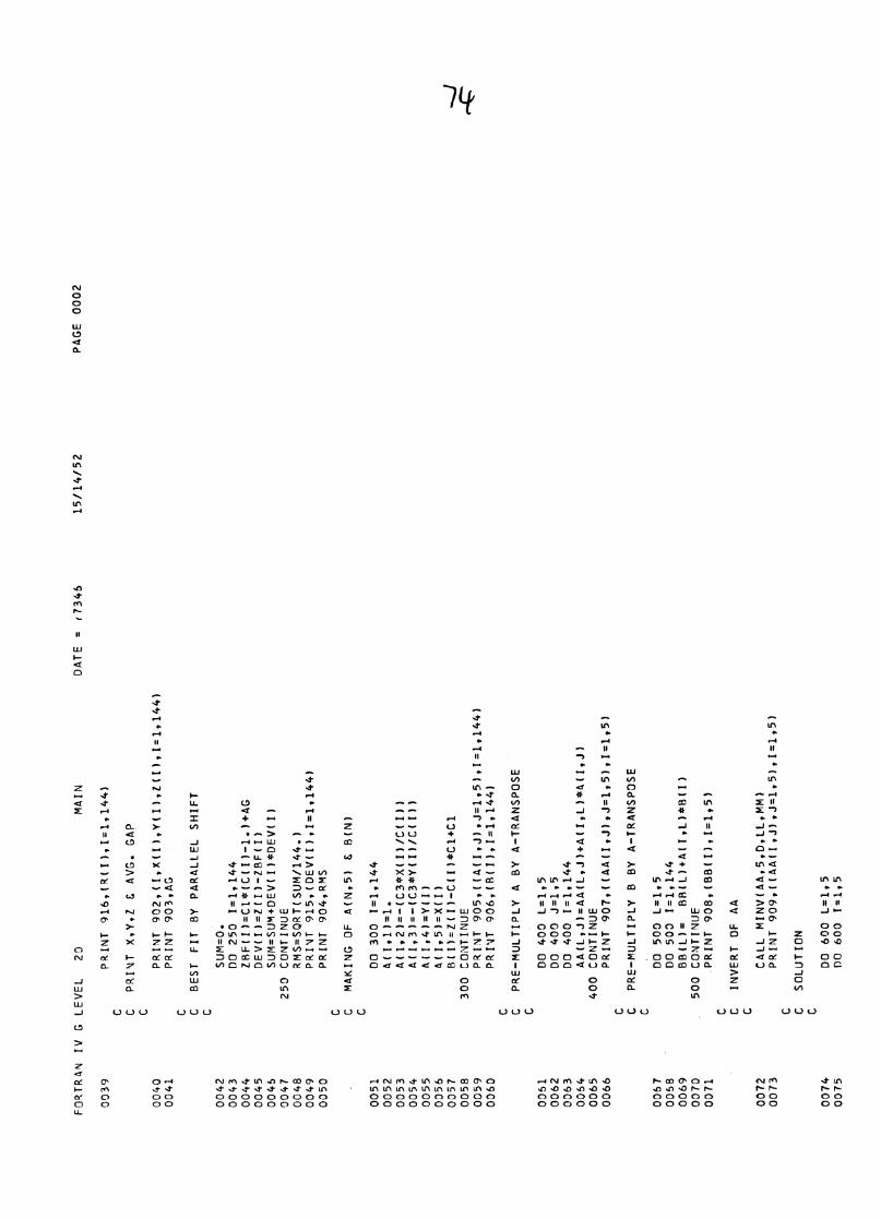
FORTRAN IV G LEVEL 20
MAIN
DATE = (7346
15/1
4/5
2P
AG
E 0
002
0039
PRINT 916,(R(1),I=1,144)
C PRIVT X,Y,Z C AVG. GAP
0040
PRINT 902,(I,X(I),Y(I)INI)11=1,144)
0041
PRINT 903,AG
C BEST FIT BY PARALLEL SHIFT
0042
SUM=0.
0043
DO 250 1=1,144
0044
ZBF(I)=C1*(C(I)-1.)+AG
0045
DEV(1)=11I)-ZBF(I)
0046
SUM=SUM+DEV(I)*DEV(I)
0047
250 CONTINUE
0048
RM
S=
S0R
T(S
UM
/144
.)0049
PRINT 915,(DEV(I),I=1,144)
0050
PRINT 904,RMS
C MAKING OF A(N,5) & B(N)
0051
DO 300 1=1,144
0052
4(I,1)=1.
0053
A(I,2)=-(C3*X(I)/C(1))
0054
A(1,3)=-(C3*Y(I)/C11))
0055
A(I,4)=YII)
0056
4(1,5)=X(I)
0057
B(1)=Z(I)-C11)*Cl+Cl
0058
300 CONTINUE
0059
PRINT 905,t(A(I,J),J=1,5),I=1,144)
0060
PRINT 906,(B(I),I=1,144)
C PRE-MULTIPLY A BY A-TRANSPOSE
0061
0062
0063
0064
AA(L,J)=AA(L,J)+A(I,L)*A(I,J)
0065
400 CONTINUE
0066
PRINT 9070(AA(I,J),J=1,5),I=1,5)
C PRE-MULTIPLY B BY A-TRANSPOSE
0067
DO 500 L=1,5
0058
DO 500 1=1,144
0069
BBIL)= BBIL)+A(I,L)*B(I)
0070
500 CONTINUE
0071
,PRINT 908,(BM1)11=1,5)
C INVERT Of AA
0072
CALL MINV(AA,5,D,LL,MM)
0073
PRINT 909,I(AA(I,J),J=1,5),I=1,5)
C SOLUTION
0074
DO 600 L=1,5
0075
DO
600 1
=1,5
DO40
0L
=1
,5DO
400
J=1,5
DO40
01=
1,1
44
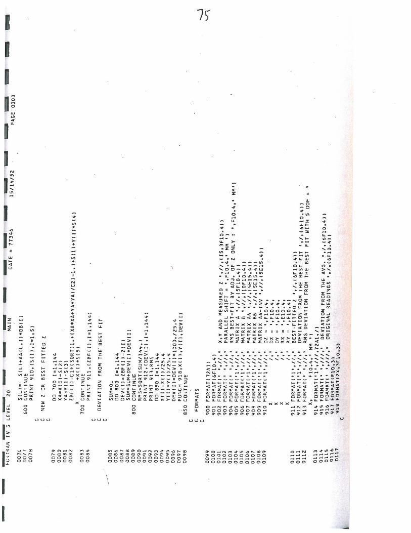
Top Related