


Languages
Pages
Legal


Nanostructured Mo-based electrode materials for
electrochemical energy storage
Journal: Chemical Society Reviews
Manuscript ID: CS-REV-10-2014-000350.R2
Article Type: Review Article
Date Submitted by the Author: 20-Oct-2014
Complete List of Authors: Hu, Xianluo; Huazhong University of Science and Technology, School of Materials Science & Engineering Zhang, Wei; Huazhong University of Science and Technology, School of Materials Science & Engineering Liu, Xiaoxiao; Huazhong University of Science and Technology, School of Materials Science & Engineering
Mei, Yueni; Huazhong University of Science and Technology, School of Materials Science & Engineering Huang, Yunhui; Huazhong University of Science and Technology, College of Materials Science and Engineering
Chemical Society Reviews

1
Nanostructured Mo-based electrode materials for
electrochemical energy storage
Xianluo Hu,* Wei Zhang, Xiaoxiao Liu, Yueni Mei, and Yunhui Huang*
State Key Laboratory of Materials Processing and Die &Mould Technology, School of
Materials Science and Engineering, HuazhongUniversity of Science and Technology,
Wuhan 430074, P. R. China
E-mail: [email protected] (X. L. Hu); [email protected] (Y. H. Huang)
Abstract: The development of advanced energy storage devices is at the forefront of
research geared towards a sustainable future. Nanostructured materials are
advantageous in offering huge surface to volume ratios, favorable transport features,
and attractive physicochemical properties. They have been extensively explored in
various fields of energy storage and conversion. This review is focused largely on the
recent progresses in nanostructured Mo-based electrode materials including
molybdenum oxides (MoOx, 2 ≤ x ≤ 3), dichalconides (MoX2, X = S, Se), and
oxysalts for rechargeable lithium/sodium-ion batteries, Mg batteries, and
supercapacitors. Mo-based compounds including MoO2, MoO3, MoO3-y (0 < y <1),
MMoxOy (M = Fe, Co, Ni, Ca, Mn, Zn, Mg, or Cd; x = 1, y = 4; x = 3, y = 8), MoS2,
MoSe2, (MoO2)2P2O7, LiMoO2, Li2MoO3, etc. possess multiple valence states and
exhibit rich chemistry. They are very attractive candidates for efficient
electrochemical energy storage systems because of their unique physicochemical
Page 1 of 99 Chemical Society Reviews

2
properties, such as conductivity, mechanical and thermal stability, and cyclability. In
this review, we aim to provide a systematic summary on the synthesis, modification,
and electrochemical performance of nanostructured Mo-based compounds, as well as
their energy storage applications in lithium/sodium-ion batteries, Mg batteries, and
pseudocapacitors. The relationship between nanoarchitectures and electrochemical
performances as well as the related charge-storage mechanism is discussed. Moreover,
remarks on the challenges and perspectives of Mo-containing compounds for further
development in electrochemical energy storage applications are proposed. This review
sheds light on the sustainable development of advanced rechargeable batteries and
supercapacitors with nanostructured Mo-based electrode materials.
1. Introduction
Nowadays the increasing environmental problems, such as global warming and
pollution, give a great impetus to reduce the society’s dependence on fossil fuels. It is
preferable to produce energy from renewable and sustainable resources (e.g., solar
and wind). The utilization of electricity generated from intermittent renewable sources
requires efficient energy storage systems (ESSs). Among clean energy technologies,
electrochemical ESSs are considered the most feasible, environmentally friendly, and
sustainable.1-6 Electrochemical ESSs such as rechargeable batteries and
supercapacitors have been widely used in portable electronics, electric vehicles, and
smart electrical grids.7-12
Page 2 of 99Chemical Society Reviews

3
Lithium-ion batteries (LIBs) are one type of rechargeable energy-storage devices
based on Li-ion shuffling between a negative electrode (also termed as anode) and a
positive electrode (cathode). During discharge, Li ions carry the current from the
anode to the cathode through the nonaqueous electrolyte and separator diaphragm,
and the process reverses in charging. Since commercialization by Sony in 1991, LIBs
have become one kind of the most popular rechargeable batteries for portable
electronics (e.g., laptops, cell phones, and digital cameras), because of high energy
density, no memory effect, and only a slow loss of capacity when not in use.
Meanwhile, the advent of LIBs has ushered in the wireless revolution, and further
stimulated a quest to power electric vehicles (EVs) and hybrid electric vehicles
(HEVs). The electrode materials are the key components of LIBs that play crucial
roles in the overall performance.13-17 In order to power EVs or HEVs, five basic
factors including energy density, power density, cost, life and safety need to be well
balanced.
Dramatic developments in next-generation electrical transportation and large-scale
ESSs for smart grids will require substantially greater amounts of materials to build
large batteries. Li is not regarded as an abundant element. The mean mass fraction of
Li in the earth’s crust is estimated to be only 20 ppm. It is also witnessed that the price
of the Li resource has been increasing in recent years, arising from more and more use
of LIBs. In contrast, the abundance and low cost of Na in the earth will become
advantageous when a large amount of materials are demanded for renewable energy
Page 3 of 99 Chemical Society Reviews

4
solutions.18-23 Moreover, Na is the second-lightest and -smallest alkali metal next to Li.
Therefore, the sacrifice in energy density is expected to be minimized if the same
electrochemical insertion is utilized for discharge-charge cycling. Owing to the
similarities in electrochemistry between Li and Na, the state-of-the-art advances in
LIBs may pave the way for developing sodium-ion batteries (SIBs). Nevertheless, Na
ion intercalation and storage mechanisms are also scientifically challenging, since Na+
ions are ∼70% larger in radius than Li+ ions. It is highly desirable to explore suitable
host materials to accommodate Na+ ions and facilitate reversible insertion/extraction
of Na+ ions. In additionto Li, Mg is another abundant element in the earth’s crust,
leading to wider availability and much lower cost. Rechargeable Mg batteries are now
gaining increasing interest especially after Aurbach’s pioneering work.24
Fundamentally, the science and technology of rechargeable Mg batteries are quite
different from those of LIBs and SIBs.25 The use of alkali metals such as Li and Na in
rechargeable batteries is enabled by the formation of a solid electrolyte interface (SEI)
layer on the surface of the electrodes via reacting with the electrolyte.26,27 The passive
SEI film hampers the transport of electrons, but is still permeable to Li+ and Na+ions.
Compared to LIBs or SIBs, it is noted that the diffuse of alkaline earth metal cations
like Mg2+ ions through interfacial passivation layers is much sluggish or even
impossible. Meanwhile, Mg2+ ions have the divalent nature and Mg metal anodes are
used in rechargeable Mg batteries. The divalent nature of Mg2+ ions enables a high
theoretical specific capacity (2205 mA h g–1).28–30 In comparison to LIBs, however,
the kinetically sluggish Mg intercalation/insertion and diffusion in cathode materials
Page 4 of 99Chemical Society Reviews
5
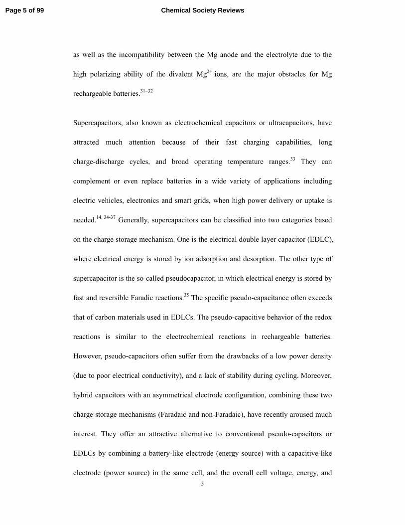
as well as the incompatibility between the Mg anode and the electrolyte due to the
high polarizing ability of the divalent Mg2+ ions, are the major obstacles for Mg
rechargeable batteries.31–32
Supercapacitors, also known as electrochemical capacitors or ultracapacitors, have
attracted much attention because of their fast charging capabilities, long
charge-discharge cycles, and broad operating temperature ranges.33 They can
complement or even replace batteries in a wide variety of applications including
electric vehicles, electronics and smart grids, when high power delivery or uptake is
needed.14, 34-37 Generally, supercapacitors can be classified into two categories based
on the charge storage mechanism. One is the electrical double layer capacitor (EDLC),
where electrical energy is stored by ion adsorption and desorption. The other type of
supercapacitor is the so-called pseudocapacitor, in which electrical energy is stored by
fast and reversible Faradic reactions.35 The specific pseudo-capacitance often exceeds
that of carbon materials used in EDLCs. The pseudo-capacitive behavior of the redox
reactions is similar to the electrochemical reactions in rechargeable batteries.
However, pseudo-capacitors often suffer from the drawbacks of a low power density
(due to poor electrical conductivity), and a lack of stability during cycling. Moreover,
hybrid capacitors with an asymmetrical electrode configuration, combining these two
charge storage mechanisms (Faradaic and non-Faradaic), have recently aroused much
interest. They offer an attractive alternative to conventional pseudo-capacitors or
EDLCs by combining a battery-like electrode (energy source) with a capacitive-like
electrode (power source) in the same cell, and the overall cell voltage, energy, and
Page 5 of 99 Chemical Society Reviews

6
power density can be improved.38-48
Nanomaterials with attractive chemical and physical properties are being explored for
their potential in energy storage applications. The design and creation of new
materials and substances that are chemically modified from the molecular and atomic
level to sizes on the nanoscale would offer significantly enhanced functions for
energy storage applications. Meanwhile, the development of advanced
nanocharacterization techniques has facilitated the fundamental molecular-level
understanding on structure-performance relationships, which are strongly related to
the grain size and size distribution, shape, chemical composition, interfaces, surface
(potentially with different electrolytes), and interactions between the constituent
domains. This knowledge, together with effective synthetic strategies, has inspired the
design and fabrication of novel nanostructured materials for a wide variety of
energy-based applications. During the past decades, much effort has been particularly
devoted to fabricating a great number of nanostructured materials as electrodes in a
range of LIBs, SIBs, Mg batteries, and supercapacitors. This research trend has been
evidenced by many important pioneering works published during the past decades.37,
49-53 As expected, a notable improvement in performance has been achieved through
recent advances in the development of advanced nanostructured materials and
understanding on charge storage mechanisms.54 In batteries and supercapacitors,
nanostructuring of electrode materials may reduce diffusion/transport lengths for both
ions and electrons, increase active sites, and relieve the volume expansion/contraction,
Page 6 of 99Chemical Society Reviews
7
thus leading to improved capacity, and higher power/energy density, and longer cycle
life. In some cases, new thermodynamics and/or kinetics allow enhanced phase
transitions and rate capability during Li+ intercalation/deintercalation. It is believed
that new development in the field of nanomaterials chemistry holds the key to further
breakthroughs in ESSs. Recently, many excellent reviews and reports on the
preparation, modification, assembly, characterization, property, and engineering of
nanostructured materials for energy storage applications have been published.5, 55-65
This article reviews recent advancements and trends in nanostructured molybdenum
oxides (MoOx, 2 ≤ x ≤ 3), dichalconides (MoX2, X = S, Se), and oxysalts for batteries
and supercapacitors with high energy and power density. Their representative crystal
structures are shown in Fig. 1. Mo-based oxides, dichalconides, and oxysalts possess
multiple valence states and exhibit rich chemistry. Recent progress has demonstrated
that nanostructured Mo-based compounds including MoO2, MoO3, MoO3-y (0 < y <1),
MMoxOy (M = Fe, Co, Ni, Ca, Mn, Zn, Mg, or Cd; x = 1, y = 4; x = 3, y = 8), MoS2,
MoSe2, (MoO2)2P2O7, LiMoO2, Li2MoO3, etc. are very promising candidates for
efficient electrochemical energy storage systems because of their unique physical and
chemical properties, such as conductivity, mechanical and thermal stability, and
cyclability. In this review, we present a summary on the synthesis, modification, and
electrochemical performance of nanostructured Mo-based compounds. Also, their
energy storage applications in the fields of LIBs, SIBs, Mg batteries, and
pseudocapacitors are emphasized. The relationship between nanoarchitectures and
electrochemical performances as well as related charge-storage mechanisms is
Page 7 of 99 Chemical Society Reviews

8
discussed. This review ends with an outlook of Mo-containing compounds for further
development in electrochemical energy storage applications.
Fig. 1 (a) Cyrstal structures of monoclinic MoO2, α-MoO3, MoS2, Mn2Mo3O8,
(MoO2)P2O7, and Li2MoO3. (b) Multivalent Mo-based electrode materials with rich
chemistry for electrochemical energy storage applications including LIBs, SIBs, Mg
batteries, and supercapacitors.
2. Nanostructured Mo-based electrode materials for LIBs
2.1 MoO2
In general, the Li-storage mechanisms for metal oxide-based anodes can be classified
Page 8 of 99Chemical Society Reviews

9
into three types:66,67 insertion reaction, alloying−dealloying, and conversion reaction.
A literature survey suggests that the oxides including early transition metal elements
such as TiO2,66-75 V2O5,
76, 77 and MoO278, 79 are often found to be lithiated though the
insertion reaction. In contrast, the other ones like CoO,80, 81 MnO,82-85 and Fe2O386
follow the conversion-reaction mechanism. The difference of their Li-cycling
reactions is probably related to the metal-oxygen bond strength. The conversion
reaction in metal oxides requires a heterogeneous charge transfer at the interfaces, Li+
and O2– in solid state, and M–O bond cleavage. The former group has a relatively
stronger metal-oxygen bond. For instance, the bond dissociation energy of Mo-O in
MoO2 is about 678 kJ mol–1, which is much higher than 368 kJ mol–1 for Co-O in
CoO.87 Therefore, the insertion reaction occurs in MoO2 without bond cleavage at
ambient temperature. MoO2 crystallizes in a monoclinic cell as illustrated in Fig. 1. In
MoO2 octahedra are distorted and Mo atoms are off-centre, leading to alternating
short and long Mo–Mo distances and Mo-Mo bonding.88 MoO2 has low metallic
electrical resistivity (8.8 × 10⁻⁵ Ω·cm at 300 K in bulk samples), high melting point,
and excellentchemical stability.89 It has been extensively investigated in LIBs,
supercapacitors, solid state fuel cells, catalysis, sensors, recording media, and
electrochromic displays due to its efficient charge transport properties.90-95
2.1.1 Lithium-storage mechanism. As a matter of fact, the Li-insertion behavior in
MoO2 was investigated 30 years ago.96 However, its electrochemical Li-storage
performance receives little attention due to the sluggish kinetics in bulk MoO2. So far,
several Li-cycling mechanisms for amorphous and crystalline MoO2 anodes in LIBs
Page 9 of 99 Chemical Society Reviews

10
have been proposed, but some of them are still controversial at present. Actually, the
crystal size and crystallinity of MoO2 materials should determine the specific
electrochemical reactions. Therefore, none of the given mechanisms is absolutely
suitable for all of the cases in MoO2-based electrodes. As summarized as follows, four
representative Li-cycling mechanisms have been proposed for MoO2.
(i) One-electron insertion (ordered LixMoO2). Bulk or micrometer-sized MoO2
accommodates Li usually through an insertion-type reaction with a theoretical
capacity of 209 mA h g–1.76
MoO2 + xLi+ + xe–1 ↔ LixMoO2 (crystalline ordered, 0 < x < 1)
During electrochemical Li-cycling reactions, Li+ storage sites are crystallographically
well-defined and the site amount determines Li+ storage capacity. The bulk or
micrometer-sized MoO2-based electrodes based on the insertion-reaction mechanism
(one-electron reduction) often suffers from poor cyclability and low capacity as a
result of the phase transition of LixMoO2 from a monoclinic structure (0 < x < 0.5) to
an orthorhombic structure (0.45 < x < 0.79).79
(ii) Four-electron conversion. Oh and coworkers studied the high-temperature
lithiation behavior of the MoO2 electrode.97 It is found that the MoO2 electrode is
lithiated with four-electron reduction by addition and continued conversion reactions
at elevated temperatures. By means of thermoelectrochemical activation, the
extension from one- to four-electron reduction is achieved. The initial crystalline
MoO2 phase can be decomposed into a nanosized mixture of metallic Mo and Li2O,
which is in turn converted to nanosized MoO2 upon forthcoming delithiation. During
Page 10 of 99Chemical Society Reviews

11
subsequent discharge-charge cycles, the as-formed nanosized MoO2 is fully lithiated
up to four-electron reduction even at room temperature. Interestingly, the
newly-formed nanosized MoO2 electrode through thermoelectrochemical activation
delivers a reversible specific capacity that is close to the theoretical four-electron
capacity 838 mA h g−1 with an excellent cycle performance at room temperature. In
this regard, nanosized MoO2 as the initial active material would be preferable for a
high-capacity four-electron conversion reaction:
MOO2 + 4Li+ + 4e– ↔ Mo + 2Li2O
With the rapid development of nanomaterials synthesis in recent decades, various
well-defined MoO2-based nanostructures have been fabricated by advanced
nanotechnology, offering elaborate candidates as high-capacity anodes for LIBs. As
expected, reducing the particle size of MoO2 will enhance the kinetic barriers for the
conversion reaction, arising from not only the enhanced heterogeneous charge transfer
and solid-state Li+ and/or O2– diffusion, but also the weaker Mo–O bond strength of
nanosized MoO2. In addition to thermoelectrochemical activation or nanostructuring,
increasing defect sites is another effective way to improve the electrochemical
performance of MoO2-based electrodes.98
(iii) Coupled insertion-conversion reaction. For nanostructured MoO2 materials,
there exists a general phenomenon that the specific capacities increase gradually
during initial charge and discharge cycles. Some researchers ascribed vaguely the
capacity increase upon cycling to the activation of the MoO2 electrode. Recently,
Zhang et al.99 and Guo et al.
100 investigated the Li storage mechanism of nanosized
Page 11 of 99 Chemical Society Reviews

12
MoO2 in detail by in-situ or ex-situ X-ray diffraction (XRD) analysis. In-situ and
ex-situ XRD results indicate that the intermediate phase of Li0.98MoO2 is generated
during the first lithiation cycle at the potential from 3.0 to 1.0 V. When further
discharged from 1.0 to 0.01 V, the crystal phase of Li0.98MoO2 is mainly retained in
the lithiated product. Only a part of intermediate Li0.98MoO2 undergoes a conversion
reaction and then decomposes into Mo and Li2O during the first discharge cycle. The
first discharge capacity is between 205 mA h g–1 (Li0.98MoO2) and 838 mA h g–1
(Li4MoO2). In the first delithiation process, both Li0.98MoO2 and Mo could be
transformed into MoO2. During the initial 30 discharge/charge cycles, most of
Li0.98MoO2 can reversibly convert into MoO2, while a part of Li0.98MoO2 is further
reduced simultaneously to Li2O and Mo upon Li+ insertion.99 After about 30
discharge/charge cycles, the lithiation reaction of MoO2 shifts from an initial insertion
type to a conversion mechanism, which is frequently observed in transition metal
oxides. The overall electrochemical reactions of the MoO2 electrode can be simplified
as:
MoO2 ↔ Li0.98MoO2 ↔ Mo + Li2O
First principle calculations also provided an elementary explanation on the gradual
increase in capacity upon cycling.101 Their calculations including geometry and
electronic structure calculation are performed by using density function theory (DFT)
on the basis of projector augmented wave (PAW) method implemented in the VASP
package. Average binding energy, density of states (DOS) and average cell voltage
were calculated. Their calculation results showed that the binding energy in MoO2 is
Page 12 of 99Chemical Society Reviews

13
large, suggesting the stable nature of MoO2. If the lithiation extent of LixMoO2
increases, the average binding energy will decrease. Miao and coworkers also
calculated the formation energy of Mo vacancies.101 The intercalation of Li in MoO2
would weaken both the Mo–Mo bond and the charge polarization of Mo vacancies,
thus greatly reducing the formation energy of Mo vacancies in LixMoO2. The
newly-formed Mo vacancies in LixMoO2 provide new active sites for Li storage, and
therefore the capacity will be enhanced. Upon further continuous cycling, however,
the capacity decays because of the broken structure of MoO2 as well as the
irrepressible structural change.
(iv) Structural defects induced Li+ storage (disordering LixMoO2). Recently, Oh’s
group further demonstrated that structural defects in amorphous MoO2 could also
serve as reversible Li+ storage sites for rechargeable LIBs.87 Amorphous MoO2
(a-MoO2) exhibits an unexpectedly high Li+ storage capacity (up to four Li per MoO2
unit), which is 4 times larger than that for the crystalline counterpart. Unexpectedly,
Mo and Li2O in the lithiated a-MoO2 are not generated upon Li-cycling. Meanwhile,
the local structural framework of a-MoO2 is maintained, suggesting that the
conversion-type lithiation does not take place. The structural defects in a-MoO2 both
facilitate Li+ diffusion pathways and increase Li+ mobility, which was evidenced by
7Li nuclear magnetic resonance (NMR) analysis.87
MoO2 + xLi+ + xe–1 ↔ LixMoO2 (disordered Li+, x < 4)
2.1.2 Nanostructured MoO2. Several synthetic approaches, such as
Page 13 of 99 Chemical Society Reviews

14
hydrothermal/solvothermal process, magnetron-sputtering, rheological phase reaction,
electrochemical deposition, and thermal evaporation, nanocasting, and thermal
reduction, have been reported for preparing well-defined MoO2 nanostructures
including nanoparticles,87, 87, 102-109 nanosheets,110 nanorods,100, 111 nanotubes,99, 111
hollow spheres,112-114 mesoporous structures,115, 116 hierarchical architectures,117-119
and thin films120, 121 as anode materials for LIBs. Nanostructuring of MoO2 can
enhance the electrochemical performance, which cannot be achieved in bulk materials.
In particular, the fabrication of a hierarchically nanostructure arouses much interest
because of its extraordinarily high active surface/interface and robust stability.
Electrode materials with hierarchical nanoarchitectures exhibit intriguing properties
by taking advantage of both the nanometer-size effects and the high stability of the
secondary-structure assemblies. Our group has reported a two-step method to grow a
hierarchically nanostructured “cellulose” MoO2 monolith as a binder-free anode for
LIBs, whereby the cotton texture acts as both a template and a stabilizer (Fig. 2).117 At
first, a sheet of cotton cloth involving phosphomolybdic acid (PMA) was converted
into a crystalline hierarchical MoO3 replica through thermal treatment in air. Then, a
hierarchically nanoparticle-organized MoO2 monolith was obtained by thermal
reduction in a (5%)H2 /Ar atmosphere at 600 ºC. The electrode made of the
“cellulose” MoO2 monolith delivers a specific capacity of 719.1 mA h g–1 at 200 mA
g–1. Zhao et al.114 reported a template-free one-step strategy to synthesize
interconnected core–shell MoO2 hierarchical microcapsules via a solvothermal route.
The nanostructured MoO2 capsules possess core–shell hierarchical architectures,
Page 14 of 99Chemical Society Reviews
15
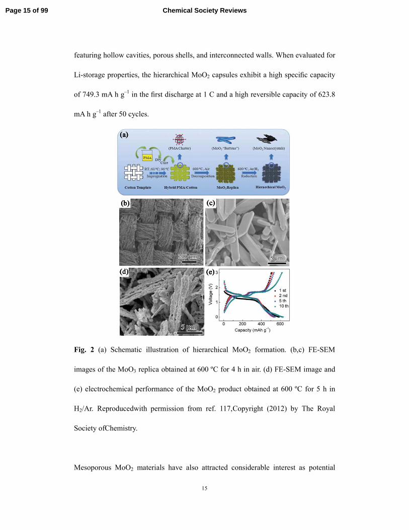
featuring hollow cavities, porous shells, and interconnected walls. When evaluated for
Li-storage properties, the hierarchical MoO2 capsules exhibit a high specific capacity
of 749.3 mA h g–1 in the first discharge at 1 C and a high reversible capacity of 623.8
mA h g–1 after 50 cycles.
Fig. 2 (a) Schematic illustration of hierarchical MoO2 formation. (b,c) FE-SEM
images of the MoO3 replica obtained at 600 ºC for 4 h in air. (d) FE-SEM image and
(e) electrochemical performance of the MoO2 product obtained at 600 ºC for 5 h in
H2/Ar. Reproducedwith permission from ref. 117,Copyright (2012) by The Royal
Society ofChemistry.
Mesoporous MoO2 materials have also attracted considerable interest as potential
Page 15 of 99 Chemical Society Reviews
16
electrode materials in LIBs.116, 122-126 Mesoporous structures can reduce solid-state
diffusion lengths for both Li+ and e– due to the nanosized walls (< 10 nm), efficiently
facilitate solvated Li+ transport through the mesopore channels (> 2 nm), and improve
the charge capacity because of intrinsic high surface areas. Hu and coworkers116
synthesized highly ordered crystallized MoO2 with a three-dimensional (3D)
bicontinuous cubic symmetry (Ia3d) mesostructure via a nanocasting strategy. The
mesoporous silica template KIT-6 filled with PMA was thermally treated at 500–700
ºC in a diluted H2 gas flow (10% H2 + 90% Ar), and the template was subsequently
removed by HF. Electrochemical testing showed that this electrode made of
mesoporous MoO2 had a typical metallic conductivity with low resistivity and
exhibited a reversible capacity as high as 750 mA h g–1 at C/20 (41.9 mA g–1) after 30
cycles. Similarly, tungsten-doped MoO2 was also synthesized by the nanocasting
method using a sacrificing template of mesoporous KIT-6.115 W-doping could help
mesoporous MoO2 to fully react with Li and the ‘‘activation process’’ disappeared.
The W-doped MoO2 material created an optimized electrode configuration by
combining the advantages of the high theoretical capacity of MoO2 and the high
electroactivity of WO2. This leads to an overall performance that is better than that of
MoO2 or WO2. However, those mesoporous MoO2-based nanostructures are
carbon-free, and the MoO2 nanocrystals are unprotected. During the continuous Li+
insertion/extraction cycles, especially for the conversion reaction involving ultrafine
Mo and Li2O, the structural stability of the whole electrode would be problematic,
thus resulting in rapid capacity fading. To further improve cyclability and rate
Page 16 of 99Chemical Society Reviews
17
capability, ordered mesoporous carbon (OMC) was used as both the nanoreactor and
the reduction agent for the fabrication of MoO2/OMC nanocomposites.127, 128 OMC
could act as the branches to connect MoO2 nanoparticles and build up a network to
ensure good electrical contact of MoO2–MoO2 and MoO2–C to increase reaction
kinetics. At the same time, OMC with a mechanical buffer function alleviated the
volume expansion and contraction and prevented the agglomeration of MoO2
nanoparticles during Li+ insertion/extraction processes.128 By using mesoporous
carbon CMK-3 as both the template and the reactant, Zhang et al.111 recently reported
the synthesis of hierarchical porous MoO2/Mo2C heteronanotubes through a one-step
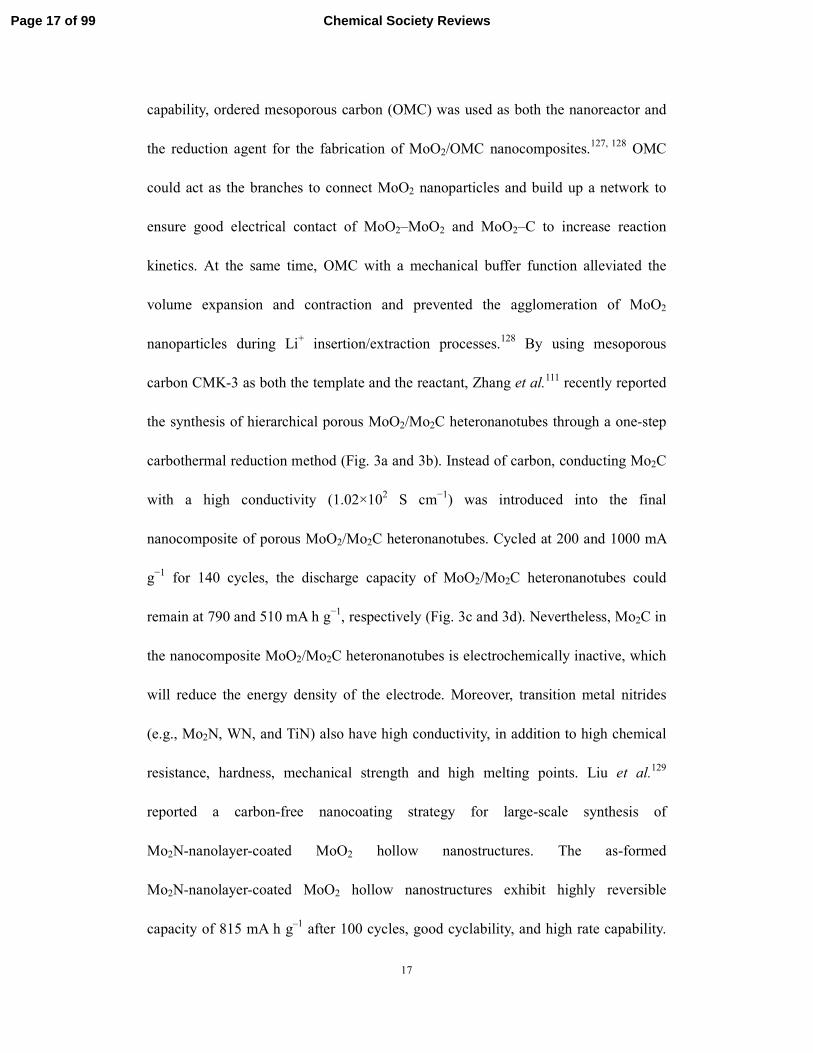
carbothermal reduction method (Fig. 3a and 3b). Instead of carbon, conducting Mo2C
with a high conductivity (1.02×10² S cm−1) was introduced into the final
nanocomposite of porous MoO2/Mo2C heteronanotubes. Cycled at 200 and 1000 mA
g−1 for 140 cycles, the discharge capacity of MoO2/Mo2C heteronanotubes could
remain at 790 and 510 mA h g−1, respectively (Fig. 3c and 3d). Nevertheless, Mo2C in
the nanocomposite MoO2/Mo2C heteronanotubes is electrochemically inactive, which
will reduce the energy density of the electrode. Moreover, transition metal nitrides
(e.g., Mo2N, WN, and TiN) also have high conductivity, in addition to high chemical
resistance, hardness, mechanical strength and high melting points. Liu et al.129
reported a carbon-free nanocoating strategy for large-scale synthesis of
Mo2N-nanolayer-coated MoO2 hollow nanostructures. The as-formed
Mo2N-nanolayer-coated MoO2 hollow nanostructures exhibit highly reversible
capacity of 815 mA h g–1 after 100 cycles, good cyclability, and high rate capability.
Page 17 of 99 Chemical Society Reviews

18
The carbon-free nanocoating of Mo2N is effective, and endows electrode materials
with high surface stability and long cycle life, in comparison to the carbon
nanocoating commonly used in other electrode materials.
Fig. 3 MoO2/Mo2C heteronanotubes: (a) schematic illustration for the preparation
process, (b) SEM image, (c) galvanostatic charge/discharge curves at a 200 mA g–1,
and (d) cycling performance. Reproduced with permission from ref. 111, Copyright
(2014) by Wiely-VCH.
2.1.3 MoO2/carbon nanohybrids. Based on literature studies and our own research
on MoO2 in the past several years, reducing the particle size, for example, to nanosize,
is possible to achieve high specific capacity via a conversion-reaction mechanism or
coupled insertion-conversion reactions. However, the long-term Li cyclability in
MoO2 is normally found to be poor, and severe capacity fading occurs upon 10–30
discharge-charge cycles. This is mainly due to the aggregation and/or pulverization of
Page 18 of 99Chemical Society Reviews

19
the highly active electrode involving ultrafine particles, the volume change, and
intensive side reactions between the electrode and the electrolyte. It is well known
that carbonaceous hybridization of nanostructured MoO2 would effectively both
enhance the Li-insertion kinetics and improve the Li-cyclability. To date, a variety of
carbon-based MoO2 nanocomposites with unique architectures have been reported.
Some of the recent data on the Li-cycling properties of nanocomposite MoO2/C are
list in Table 1. For the metal oxides based on the conversion reaction mechanism, the
large volume change could result in pulverization and aggregation of the active
materials, thus decreasing the reversible capacity upon cycling. Also, those transition
metal oxides are normally electrically insulting. We and others have shown that it is
highly desirable to grow small metal oxide nanoparticles on (or in) a carbon-based
matrix to shorten diffusion length of ions and expedite electron transport, enhancing
the capacity, rate capability and cycle life.130-132 Among the various carbonaceous
materials, graphene typically exhibits superior electrical conductivity, large surface
area, structural flexibility, and chemical stability. It can host nanostructured electrode
materials for energy applications.133-135 The graphene layers can offer a support for
anchoring nanoparticles and work as a highly conductive matrix providing good
contact between them. Importantly, graphene layers prevent the volume
expansion/contraction and the aggregation of nanoparticles effectively during charge
and discharge processes. Meanwhile, the integration of inorganic nanostructures with
the graphene layers may reduce the restacking of graphene sheets and consequently
maintain the high surface area.45 In this regard, both the lithium-storage capacity and
Page 19 of 99 Chemical Society Reviews
20
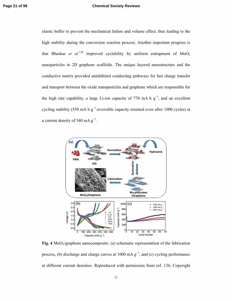
the cycling performance of graphene-based nanomaterials will be improved. We
reported the large-scale fabrication of unprecedented self-assembled hierarchical
MoO2/graphene nanoarchitectures through a facile solution-based method combined
with a subsequent reduction process (Fig. 4a), where nanostructured MoO2 was first
stabilized by reduced graphene oxide sheets.136 PMA and graphene oxide (GO)
reacted with hydrazine hydrate in solution to produce a Mo-precursor/graphene
composite. Then, the resulting composite was further annealed at 500 ºC for 5 h in a
reducing H2/Ar atmosphere, and self-assembled hierarchical MoO2/graphene
nanoarchitectures were finally formed. Our results showed that the electrode made of
the resulting hierarchical MoO2/graphene delivered a high capacity of 597.9 mA h g–1
over 70 cycles with a Coulombic efficiency of ∼98% at a high current density of 1000
mA g–1 (Fig. 4b and 4c). In order to buffer the volume effect arising from the
conversion reaction, we further proposed a simple
impregnation–reduction–carbonization (IRC) route for the assembly of ultrafine
MoO2 nanoparticles (< 2 nm) into a carbon cloth.137 Interestingly, the MoO2/C
composite exhibited excellent cycling stability (600 cycles) and a high reversible
capacity of 734 mA h g–1 as an anode material for LIBs. Our results showed ultrafine
MoO2 nanoparticles embedded in the nanoporous carbon matrix would be highly
favorable for the conversion reaction. The MoO2 nanoparticles with high surface area
and abundant surface defects may enhance the heterogeneous charge transfer kinetics,
ion diffusion, and capacity. In particular, the nanoporous nature of the as-formed
hybrid could not only facilitate fast Li-ion and electron transport but also act as an
Page 20 of 99Chemical Society Reviews
21
elastic buffer to prevent the mechanical failure and volume effect, thus leading to the
high stability during the conversion reaction process. Another important progress is
that Bhaskar et al.138 improved cyclability by uniform entrapment of MoO2
nanoparticles in 2D graphene scaffolds. The unique layered nanostructure and the
conductive matrix provided uninhibited conducting pathways for fast charge transfer
and transport between the oxide nanoparticles and graphene which are responsible for
the high rate capability, a large Li-ion capacity of 770 mA h g–1, and an excellent
cycling stability (550 mA h g–1 reversible capacity retained even after 1000 cycles) at
a current density of 540 mA g–1.
Fig. 4 MoO2/graphene nanocomposite: (a) schematic representation of the fabrication
process, (b) discharge and charge curves at 1000 mA g–1, and (c) cycling performance
at different current densities. Reproduced with permission from ref. 136, Copyright
Page 21 of 99 Chemical Society Reviews

22
(2011) by American Chemical Society.
.
Table 1. Morphology and electrochemical performances of carbon-based MoO2
nanocomposites prepared by different methods.
Carbon-based MoO2
nanocomposites
Methods Current density
(mA/g)
Capacity
(mA h/g)
cycle
number
Ref.
Hierarchical
MoO2/graphene
nanoarchitecture
Solution and
annealed
1000 600 70 136
MoO2 nanoparticles
embedded in carbon
nanofibers
Solution and
annealed
50 734 350 137
Carbon-coated MoO2
nanofibers
Electrospinning 50 762.7 50 138
MoO2/graphene thin film Layer-by-layer
self-assembly
47.8 675.9 100 139
Hierarchical carbon/MoO2
core-shell spheres
Hydrothermal 167.6 600 60 140
MoO2-ordered mesoporous
carbon hybrids
Solvothermal 100 1049.1 50 128
Graphene-MoO2
hierarchical
nanoarchitecture
In-situ reduction 167.6 997.1 50 140
3D graphene supported
MoO2
Chemical vapor
deposition
200 986.9 150 142
Cage-like MoO2/carbon Hydrothermal 200 692.5 80 143
MoO2@C nanoparticles Hydrothermal 100 730 60 144
MoO2-ordered mesoporous
carbon
Carbon thermal
reduction
50 689 50 145
Hierarchical MoO2/C
spheres
Hydrothermal 200 812 150 146
Mesoporous carbon-MoO2 Carbothermal
reduction
83.8 581 30 127
MoO2/multiwalled carbon
nanotubes
Hydrothermal 100 1143 200 147
Carbon-coated
MoO2nanospheres
Hydrothermal and
annealing
838 650 30 146
MoO2/graphite oxide Solvothermal 100 720 30 149
Interconnected MoO2
nanocrystals with carbon
Hydrothermal 200 640 70 150
Page 22 of 99Chemical Society Reviews

23
nanocasting
MoO2/graphene Hydrothermal 540 550 1000 138
Nanosized MoO2/C Spray pyrolysis 83.8 225 2 151
MoO2- porous carbon
hollow spheres
Solution and
annealing
50 640 80 152
MoO2/carbon nanowires Oil bath and
calcination
200 500 20 153
Carbon/MoO2 composite Template 83 760 20 154
MoO2/graphene Solution and
annealing
200 640 50 155
MoO2/graphene Hydrothermal and
calcination
100 1009.9 60 156
Carbon coated MoO2
nanobelts
Hydrothermal and
calcination
100 617.2 30 157
2.1.4 MoO2 additive.In addition to the direct use as active materials, MoO2 is
attractive as a conducting additive to modify other electrode materials for LIBs
because of its high electric conductivity and chemical stability. For instance, we
prepared MoO2 -modified TiO2 nanofibers, comprising a core of TiO2 nanofibers and a
thin metal-like MoO2 nanolayer, through electrospinning and layer-by-layer (LBL)
self-assembly processes.158 The thickness of the MoO2 nanolayer could be tuned
easily by altering the precursor concentration or the LBL cycles. Results showed that
the electrochemical performance of surface-modified TiO2 was distinctively improved,
compared with the pure TiO2 nanofibers. The MoO2-modified TiO2 nanofibers
exhibited a high discharge capacity of 514.5 mA h g–1 at 0.2 C over 50 cycles and
excellent rate capability. This also demonstrates that enhanced physical and/or
chemical properties can be achieved through proper surface modification. Besides,
MoO2 was also reported to modify the surface of the LiFePO4/C electrode
materials.159 Despite of the low electric resistivity of MoO2, its own structural
Page 23 of 99 Chemical Society Reviews
24
instability needs to be evaluated when it is employed as an additive or modification
agent to improve the surface nature of other electrode materials. In particular, MoO2
may be oxidized to a higher oxidation state, when used at a high potential. Also, the
thickness and the uniformity of the MoO2 layer are crucial to the Li+ storage
performance of MoO2-modifed nanocomposite electrode materials.
2.1.5 Other MoO2-based nanocomposites. Other carbon-stabilized MoO2 anode
materials for LIBs include carbon-coated MoO2 nanoparticles,144,148,150
nanofibers,153,160 and nanobelts,157 nanosized MoO2 in porous carbon,127, 128, 145, 152
MoO2/multiwalled carbon nanotubes,148 and MoS2 coated MoO2 nanonetworks.161
The MoO2@MoS2 nanocomposite is composed of nanocrystalline - nanoporous
MoO2 partially covered with few atomic layers of MoS2.161 The obtained porous
MoO2@MoS2 networks delivered a reversible capacity as high as 1163 mA h g–1 at a
current density of 100 mA g–1 after 80 cycles. Reversible capacities of 1125 and 654
mA h g–1 were also achieved at current densities of 200 and 500 mA g–1 after 80
cycles, respectively. Yoon and Manthiram162 reported a microwave-assisted
hydrothermal process to prepare carbon-decorated WOx-MoO2 (x = 2 and 3) nanorods
as anode materials. The WOx-MoO2 anodes showed excellent capacity retention as the
carbon could provide an elastic matrix for absorbing the volume
expansion–contraction smoothly and prevent aggregation of the WOx-MoO2 nanorods
during cycling.
2.2 MoO3
Page 24 of 99Chemical Society Reviews

25
2.2.1 Crystal structure. MoO3 is an attractive example of a prospective electrode
material for LIBs with high capacity. It has been investigated as both cathode and
anode materials because of its unique layered structure.163-165 Two basic polymorphs
of MoO3 include thermodynamically stable orthorhombic α-phase and metastable
monoclinic β-phase with a ReO3-type structure (Fig. 5).166 The most important
characteristic of α-MoO3 is the structural anisotropy. The crystal phase of α-MoO3
possesses an orthorhombic layered structure parallel to (010) planes. Each layer is
composed of two interleaved sub-layers, each of which is formed by corner-sharing
octahedra along [001] and [100]; the two sub-layers stack together by sharing the
edges of the octahedra along [001].167 An alternate stack of these layered sheets along
[010] would lead to the formation of α-MoO3, where a van der Waals interaction
would be the major binding force between the piled sheets.168
Fig. 5 Structure of α-MoO3 showing the available empty sites for Li insertion.
Reproduced with permission from ref. 166, Copyright (2012) by Elsevier.
Page 25 of 99 Chemical Society Reviews

26
2.2.2 MoO3 cathodes. In 1970s MoO3 was proposed as a cathode material for
secondary solid-state ion batteries.163, 164, 169-175 As shown in Fig. 6, two types of
empty sites are available for hosting foreign ions like Li+.166 The interlayer distance
has been determined to be 6.929 Å.176 The reversible electrochemical behaviour of
MoO3 electrodes can be explained on the grounds of topotactic redox reactions. The
interleaved sheets of MoO6 octahedra are retained as two-dimensional matrix units
during the insertion and deinsertion processes. Although the guest ions can be well
accommodated without structural change in principle, the spacing between the
interlayers in the MoO3 host could be enlarged due to lithium uptake.177-179 The
overall redox reaction of intercalation could be described as:176
MoO3 + xLi+ + xe– ↔ LixMoO3
The kinetically accessible charge range amounts to 0.1 ≤ x < 1.5 with the lower limit
of x depending on the precedent cathodic load.170 At the initial cathodic stage of Li+
uptake, it is proved that two phases of MoO3 and LixMoO3 (x < 0.25) coexist at a
potential of around 2.8 V vs. Li. A second cathodic stage involves the solid solution of
LixMoO3 (0.25 < x < 0.5) at the potentials ranging from 2.8 to 2.4 V. At the final
cathodic stage, the solid solution of LixMoO3 (1 < x < 1.5) is present at the potential
lower than 2.4 V. Reduction beyond x = 1.5 would result in irreversible changes in the
oxide structure. Also, complete re-oxidation (Li+ extraction) to the binary oxide is
kinetically hindered presumably, as a result of small structural changes. It has been
reported that the accessible range of reversible Li+ intercalation/deintercalation is 0.1
Page 26 of 99Chemical Society Reviews

27
≤ x < 1.5.180 The electronic conductivity of LixMoO3 depends on the x value.181 In
general, the conductivity increases with x up to a maximum value, and then drops
significantly on further Li+ intercalation. Namely, the conductivity is relatively poor at
the end of discharge. On the other side, the completely charged state, the oxide MoO3
is practically an insulator. The specific conductivity of LixMoO3 (prepared by
lithiation with n-butyl lithium) in the range of 0.3 ≤ x ≤ 0.9 was in the order of 10−1 S
cm–1, with a maximum value at x = about 0.6.181 The electronic and Li+-ionic
conductivity of LixMoO3 varies with x by orders of magnitude. Mai and coworkers182
proved that the electroactivity of MoO3 nanobelts was highly improved through
lithiation. The lithiated MoO3 nanobelts exhibited excellent cycling capability, with a
capacity retention rate of 92 % after 15 cycles, while the non-lithiated nanobelts
retained only 60% (Fig. 6). Transport measurements also showed that the conductivity
of a lithiated MoO3 nanobelt (10–2 S cm–1) is increased by nearly two orders of
magnitudes compared to that of a non-lithiated MoO3 nanobelt (10–4 S cm–1).
Page 27 of 99 Chemical Society Reviews

28
Fig. 6 (a) SEM image for the MoO3 nanobelts. (b) Potential vs. capacity curves for the
first cycle of charge-discharge process of the nanobelts before and after lithiation. (c)
The discharge capacity as a function of the cycle number for the MoO3 nanobelts
before and after lithiation. (d) I-V transport measurements of single nanobelt
fabricated devices using the samples before and after lithiation. Reproduced with
permission from ref. 182, Copyright (2007) by Wiley-VCH.
2.2.3 MoO3 anodes. Utilization of MoO3 as an anode material has been paid much
attention during the past decade. When tested in the potential window of 0.01–3.0 V
vs. Li, MoO3 has been found to follow the conversion-reaction mechanism:183
MoO3 + 6Li+ + 6e– ↔ 3Li2O + Mo
The theoretical specific capacity reaches as high as 1117 mA h g–1, which
approximates three times larger than that of graphite. However, poor ionic and
electronic conductivity of MoO3 often limits its electrochemical performance.
Nanostructuring, carbon hybridization, and pre-lithiation are the general strategies for
Page 28 of 99Chemical Society Reviews
29
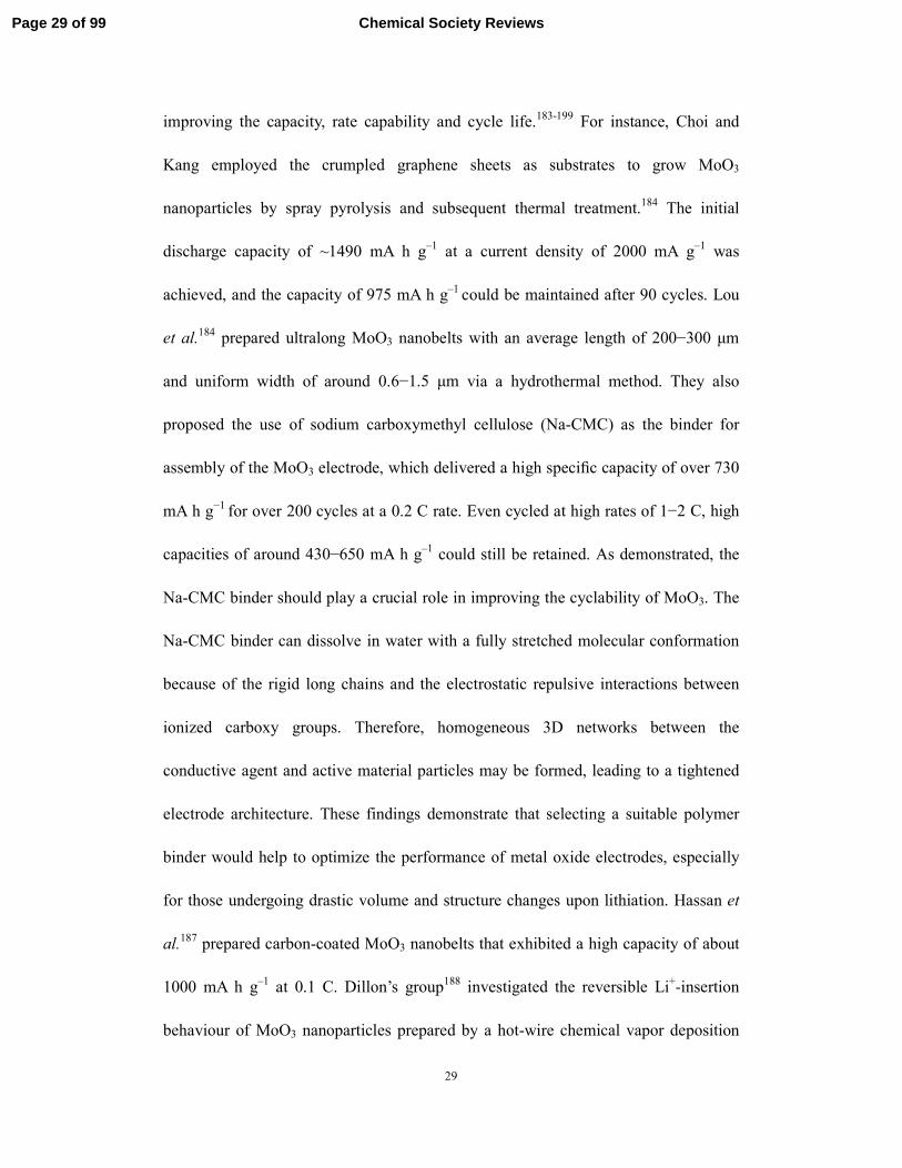
improving the capacity, rate capability and cycle life.183-199 For instance, Choi and
Kang employed the crumpled graphene sheets as substrates to grow MoO3
nanoparticles by spray pyrolysis and subsequent thermal treatment.184 The initial
discharge capacity of ~1490 mA h g–1 at a current density of 2000 mA g–1 was
achieved, and the capacity of 975 mA h g–1 could be maintained after 90 cycles. Lou
et al.184 prepared ultralong MoO3 nanobelts with an average length of 200−300 µm
and uniform width of around 0.6−1.5 µm via a hydrothermal method. They also
proposed the use of sodium carboxymethyl cellulose (Na-CMC) as the binder for
assembly of the MoO3 electrode, which delivered a high specific capacity of over 730
mA h g−1 for over 200 cycles at a 0.2 C rate. Even cycled at high rates of 1−2 C, high
capacities of around 430−650 mA h g–1 could still be retained. As demonstrated, the
Na-CMC binder should play a crucial role in improving the cyclability of MoO3. The
Na-CMC binder can dissolve in water with a fully stretched molecular conformation
because of the rigid long chains and the electrostatic repulsive interactions between
ionized carboxy groups. Therefore, homogeneous 3D networks between the
conductive agent and active material particles may be formed, leading to a tightened
electrode architecture. These findings demonstrate that selecting a suitable polymer
binder would help to optimize the performance of metal oxide electrodes, especially
for those undergoing drastic volume and structure changes upon lithiation. Hassan et
al.187 prepared carbon-coated MoO3 nanobelts that exhibited a high capacity of about
1000 mA h g–1 at 0.1 C. Dillon’s group188 investigated the reversible Li+-insertion
behaviour of MoO3 nanoparticles prepared by a hot-wire chemical vapor deposition
Page 29 of 99 Chemical Society Reviews

30
(HWCVD) technique. The anode made of MoO3 nanocrystals displayed both a
durable reversible capacity of 630 mA h g–1 and durable high rate capability. The
capacity did not decay after 150 cycles at a C-rate of C/2 between 3.5 and 0.005 V,
compared to micrometer-sized MoO3 particles where the capacity faded quickly.
First-principle calculations by Dillon et al.188 also indicated that the MoO3
nanoparticles maintained some structural integrity due to the heavy Mo-framework, in
spite of a large volume expansion. Combining the XRD results with the theoretical
calculations, Dillon et al.188 considered that amorphization of MoO3, instead of
conversion reactions, could occur during the Li-cycling processes.
2.3 MoO3-x
Substoichiometric molybdenum oxide (MoOx, 2 < x < 3) or reduced molybdenum
oxide is another attractive electrode material and possesses all the advantages that
MoO3 has.200-206 Moreover, the conductivity can be improved as a result of the
intrinsic oxygen vacancies, compared to MoO3. However, those oxygen deficient
structures in early studies were limited by low recharge efficiency and poor cycling
stability. Christian et al.200 studied the electrochemical behaviour of Mo4O11
(MoO2.75), Mo17O47 (MoO2.765), Mo8O23 (MoO2.889), and Mo9O26 (MoO2.875) cathode
materials using a LiClO4/propylene carbonate electrolyte. Among them, Mo17O47
exhibited the greatest reversible capacity (1.5 Li/Mo) after several deep
discharge-charge cycles in the potential range between 2.9 and 1.4 V. It was also
found that the Li+-diffusion coefficients and the variations of lattice parameters of the
Page 30 of 99Chemical Society Reviews

31
non-stoichiometric Mo oxides depended on the depth of discharge.207 Fuentes and
coworkers synthesized reduced molybdenum oxide, Mo4O11, by a solid state reaction
between MoO3 and MoO2.205 Two polymorphs of orthorhombic γ-Mo4O11 and
monoclinic γ’-Mo4O11 were investigated as the cathode materials. They incorporated a
similar number of Li+ per metal atom (Li/Mo = 2.12 and 2.25, respectively). Detailed
studies on the insertion reaction kinetics suggested that the insertion-induced
reduction of γ-Mo4O11 and γ’-Mo4O11 went through different mechanisms.205
Solid-state lithium batteries fabricated by the thin film technology are attracting
interest as micro-batteries. Ohtsuka et al.204 prepared Li/MoO3-x thin film batteries by
using a RF sputtering method, in which MoO3-x has a larger specific capacity than
other cathode films (e.g., LiMn2O4 film). At the discharge current density of 10 µA
cm–2, the thin-film Li/MoO3-x batteries had discharge capacities of 290 mA h cm–2,
and hold the promise for flexible energy-storage devices as well as further
miniaturization. Jung et al.202 prepared nanostructured MoO3−y powders as anode
materials by ball-milling. Oxygen deficiency increased with the milling time. The
ball-milled MoO3−y could uptake more than 6 Li/Mo by an addition reaction followed
by a conversion reaction, wherein the reactivity was strongly dependent on the
oxygen deficiency. The ball-milled MoO3−y samples exhibited a high initial discharge
capacity of 1100 mA h g−1 with capacity fading upon cycling (∼620 mA h g−1 after 35
cycles). Compared to bulk MoO3, ball-milled MoO3−y powders displayed significantly
improved cyclability, possibly arising from the smaller crystallite size and/or low
crystalline nature. Sunkara et al.203 grew vertical nanowire arrays of MoO3−x on
Page 31 of 99 Chemical Society Reviews

32
metallic substrates in a hot-filament chemical vapor deposition reactor. At a current
density of 50 mA g−1, the nanowire arrays of MoO3−x showed high-capacity retention
of ∼630 mA h g−1 for up to 20 cycles. Besides the progresses in electrode materials
for Li+-ion batteries, the substoichiometric molybdenum oxides have been recently
used to enhance hole exchange in optoelectronic devices based on organic
semiconductors (OSCs), such as organic light-emitting diodes (OLEDs) and organic
photovoltaics (OPVs), because of their improved n-type conductivity originated from
intrinsic oxygen vacancies.208
2.4 Hydrated Mo-based oxides
Li insertion in hydrated Mo-based oxides has been investigated as cathodes for LIBs.
As described above (Fig. 5), anhydrous MoO3 contains double sheets of MoO6
octahedra. In contrast, single sheets are found in hydrated MoO3 (MoO3H2O,
MoO32H2O).175 By dehydration, the intercalated water could be first lost, and then
neighboring sheets condense into double sheets as the final water is lost.209 Julien et
al.210-213 performed in-depth studies of hydrated MoO3 for cathode applications.
Polycrystalline MoO30.5H2O and amorphous MoO3H2O were prepared by an ionic
resin exchange technique.210 It was found that the chemical diffusion coefficient of
Li+ ions for polycrystalline MoO30.5H2O decreased from ~3 × 10⁻⁸ to 3 × 10⁻⁹ cm2
s–1 as the number of inserted Li+ increased from 0.05 to 1.5. For amorphous
MoO3H2O, however, the diffusion coefficient remained nearly the same with Li
insertion at a higher value of ~3 × 10⁻⁸ cm2 s–1. The decrease in the diffusion
Page 32 of 99Chemical Society Reviews
33
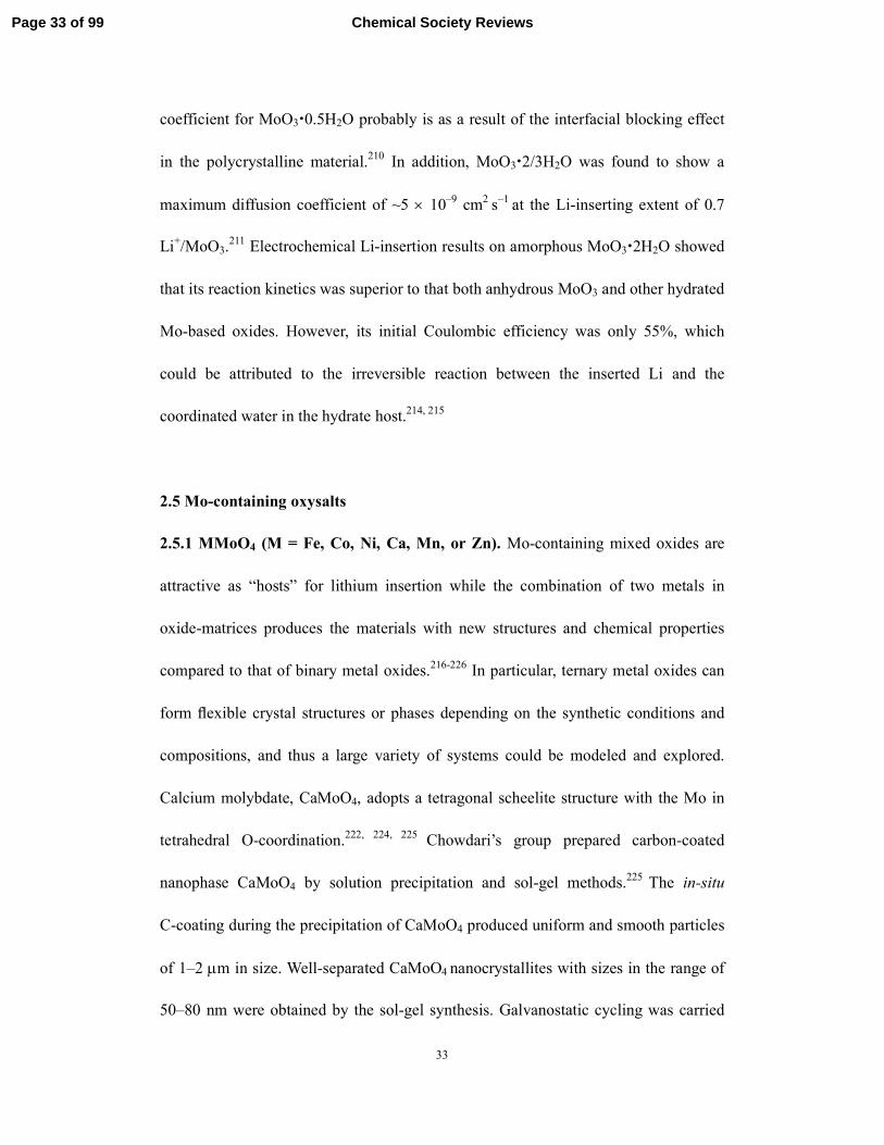
coefficient for MoO30.5H2O probably is as a result of the interfacial blocking effect
in the polycrystalline material.210 In addition, MoO32/3H2O was found to show a
maximum diffusion coefficient of ~5 × 10⁻⁹ cm2 s–1 at the Li-inserting extent of 0.7
Li+/MoO3.211 Electrochemical Li-insertion results on amorphous MoO32H2O showed
that its reaction kinetics was superior to that both anhydrous MoO3 and other hydrated
Mo-based oxides. However, its initial Coulombic efficiency was only 55%, which
could be attributed to the irreversible reaction between the inserted Li and the
coordinated water in the hydrate host.214, 215
2.5 Mo-containing oxysalts
2.5.1 MMoO4 (M = Fe, Co, Ni, Ca, Mn, or Zn). Mo-containing mixed oxides are
attractive as “hosts” for lithium insertion while the combination of two metals in
oxide-matrices produces the materials with new structures and chemical properties
compared to that of binary metal oxides.216-226 In particular, ternary metal oxides can
form flexible crystal structures or phases depending on the synthetic conditions and
compositions, and thus a large variety of systems could be modeled and explored.
Calcium molybdate, CaMoO4, adopts a tetragonal scheelite structure with the Mo in
tetrahedral O-coordination.222, 224, 225 Chowdari’s group prepared carbon-coated
nanophase CaMoO4 by solution precipitation and sol-gel methods.225 The in-situ
C-coating during the precipitation of CaMoO4 produced uniform and smooth particles
of 1–2 µm in size. Well-separated CaMoO4 nanocrystallites with sizes in the range of
50–80 nm were obtained by the sol-gel synthesis. Galvanostatic cycling was carried
Page 33 of 99 Chemical Society Reviews

34
out over 50 cycles in the range of 0.005–2.5 V at a current rate of 10 mA g–1 for the
first two cycles and at 60 mA g–1 for all other cycles. Cycling was also performed
with upper cutoff voltages of 2.0 and 3.0 V for the sol-gel and C-coated CaMoO4. It
was found that the cutoff voltage of 2.5 V exhibited the best performance. The
C-coating enabled high inter-particle electronic conductivity of the otherwise
insulating CaMoO4, leading to the best performance of carbon-coated CaMoO4
nanoparticles with a specific capacity of 508 mA h g–1 and a Coulombic efficiency
higher than 98%. A plausible mechanism involving the formation - decomposition of
the oxide bronze “LixMoOy” was proposed for the first discharge and subsequent
charge – discharge cycling of CaMoO4.
Yu and coworkers218 reported a general hydrothermal route for preparing different
phases and morphologies of molybdate hydrates MMoO4nH2O (M = Co, Ni, Mn, n =
0, 3/4, 1) nano/microcrystals, whereby NiMoO4H2O microflowers, MnMoO4H2O
microparallelogram plates, and CoMoO43/4H2O microrods could be selectively
synthesized (Fig. 7). After further annealing at a temperature of 500–550 ºC, they
could be transformed into anhydrous molybdates. The electrochemical Li-storage
performances of MMoO4 (M = Ni, Co) nanorod bundles and MnMoO4microrods were
evaluated. The first reversible discharge specific capacity for NiMoO4 could reach up
to 850 mA h g–1 at 0.1 mA cm–2 within a potential range of 1.2–4.0 V, which is higher
than those for CoMoO4 (130 mA h g–1) and MnMoO4 (180 mA h g–1). It was proposed
that such a high capacity of NiMoO4 was assigned to a large amount of vacancies in
Page 34 of 99Chemical Society Reviews

35
the structure of NiMoO4 nanorod bundles, in which Li+ ions could be reversibly
incorporated.
Fig. 7 FE-SEM images of MMoO4nH2O (M = Co, Ni, Mn, n = 0, 3/4, 1)
nanostructures and microstructures: (a, b) NiMoO4H2O microflowers, (c, d)
MnMoO4H2O microparallelogram plates, (e, f) CoMoO43/4H2O microrods.
Reproduced with permission from ref. 218, Copyright (2008) by American Chemical
Society.
Oriented 1D nanomaterials are acknowledged as one of the promising solutions to
future-generation LIBs with high performances because of their large surface area,
Page 35 of 99 Chemical Society Reviews

36
short transport path for ions and electrons, and buffering function for volume
change.51, 53, 227 Lou’s group reported the synthesis of AMoO4nH2O (A = Ni, Co)
nanorods through a hydrothermal method.228 The size of the nanorods could be easily
controlled, and self-assembled growth of oriented NiMoO4nH2O nanorod arrays on
Ti-foil substrates was achieved. The resulting AMoO4 (A = Ni, Co) was investigated
as the cathode materials for LIBs (Fig. 8). The capacities of about 120 mA h g–1 could
be retained after 50 cycles. Kim et al.229 obtained NixCo1-xMoO4 (0 ≤ x ≤ 1) nanowire
electrodes by employing a hydrothermal method with post-annealing. The electrodes
made of Ni0.75Co0.25MoO4 nanowires delivered a high reversible capacity of about 520
mA h g–1 after 20 cycles at a current densityof 196 mA g–1. This enhanced
electrochemical performance of Ni0.75Co0.25MoO4 nanowires with high Ni content was
ascribed to their larger surface area and efficient electron transport path facilitated by
their 1D nanostructure.
Page 36 of 99Chemical Society Reviews

37
Fig. 8 Cyclic voltammograms with a scan rate of 0.5 mV s–1 for the first five cycles,
voltage-capacity profiles with a current density of 50 mA g–1, and cycling
performances of NiMoO4 (A, B, and C) and CoMoO4 (D, E, and F) nanorod
electrodes between 1.2 and 3.2 V (vs Li+/Li). Reproduced with permission from ref.
228, Copyright (2008) by American Chemical Society.
2.5.2 Mo-cluster oxysalts. In recent years, a number of interesting pioneer works on
hexagonal Mo-cluster compounds including LiHoMo3O8, A2Mo3O8 (A = Zn, Co),
LiYMo3O8, and Mn2Mo3O8 as anode materials have been published by Chowdari’s
group.230, 231 These studies are very important for understanding the Li-cycling
Page 37 of 99 Chemical Society Reviews

38
mechanisms of the Mo-cluster oxides, and their potential applications in Li-storage
devices. We recently prepared hierarchically nanostructured Mn2Mo3O8–graphene
nanocomposites in large quantities through a facile two-step reduction approach.232
Typically, phosphomolybdic acid and manganese acetate reacted with hydrazine
hydrate in solution, accompanied with the reduction of graphene oxide to graphene by
hydrazine hydrate, leading to the formation of a Mn-Mo-precursor–graphene
composite. Then, this intermediate product was further treated at 550 ºC for 5 h in a
reducing H2/Ar atmosphere to obtain the final product. As displayed in Fig. 9, a large
number of hierarchical architectures consisting of secondary micro-spheres of ~3–5
µm in diameter, are clearly observed. The high-magnification SEM images in Fig. 9a
and 9b indicate that the hierarchical architectures are built from Mn2Mo3O8
nanosheets with a thickness of 10–15 nm and a width of 80–120 nm. The reversible
capacity of the nanocomposite electrode reached 920 ± 5 mA h g–1atthe 20th cycle
with a Coulombic efficiency of ~98%. As shown in Fig. 9c, the reversible specific
capacity gradually increased in the initial cycles and kept steady in the following
cycles. After 40 discharge and charge cycles, the composite electrode still exhibited a
reversible capacity of 950 ± 5 mA h g–1 at a current density of 200 mA g–1. Fig. 9d
shows the cycling behaviour of the Mn2Mo3O8–graphene hybrid at different
charge-discharge current densities. Even at a high current density of 1500 mA g–1, the
specific capacity was as high as 671 ± 5 mA h g–1, indicating the excellent rate
capability. The enhanced capacity and cyclability of the nanocomposite could benefit
from the synergistic effects of the nanohybridization: the unique hierarchical
Page 38 of 99Chemical Society Reviews
39
nanoarchitectures composed of the primary Mn2Mo3O8 nanocrystals and ultrathin
graphene sheets. The role of graphene during cycling reaction, and the Li-cycling
mechanism for the hierarchically structured Mn2Mo3O8–graphene nanohybrid are
worth further investigation. Furthermore, we recently develop a facile and scalable
strategy to prepare the Fe2Mo3O8/reduced graphene oxide (rGO) nanocomposites
through a solution-based method combined with a subsequent heat treatment
process.233 Fe2Mo3O8 nanoparticles of 10–15 nm were uniformly distributed on the
rGO nanosheets. The Fe2Mo3O8/rGO electrode delivered a high specific capacity of
835 mA h g–1 after 40 discharge/charge cycles at 200 mA g–1. A possible Li-cycling
mechanism was proposed based on in-situ XRD analyses. It was found that the
reversible conversion reaction involved the decomposition of Fe2Mo3O8 and the
formation of metallic Mo, Fe and Li2O upon cycling.
Page 39 of 99 Chemical Society Reviews

40
Fig. 9 (a–d) FESEM images of the hierarchical Mn2Mo3O8–graphene hybrid.
(e)Cycling performance of the Mn2Mo3O8–graphene composite electrodes cycled in
the voltage range of 3–0.01 V vs. Li at 200 mA g–1. (f) Capacity retention of the
Mn2Mo3O8–graphene composite at various current densities of 100, 200, 500, 1000
and 1500 mA g–1. Reproduced with permission from ref. 232, Copyright (2011) by
The Royal Society of Chemistry.
2.5.3 Bronze Mo-based oxides. As well known, α-MoO3 readily takes part in
topotactic reactions because of its unique layered crystal structure.163, 170, 177 Mo-based
Page 40 of 99Chemical Society Reviews

41
bronzes (AxMoO3, A = H, Li, Mg, etc.) can be formed though intercalation of group
IA and IIA ions, where α-MoO3 reacts with solids (e.g. LiI), vapors (e.g. CH3OH),
and liquids (e.g. n-butyl lithium solutions), electrochemically in aqueous and
nonaqueous media.134, 179, 234 The interlayer spacing (d) between the MoO3 slabs in the
host structure is usually enlarged as a result of the foreign-ion uptake, but the guest
ions would not disrupt the primary Mo–O bonding within the individual MoO3-type
slabs. The electrochemical Li-insertion properties of bronze Mo-based oxides have
aroused much attention for LIB applications. Combined electrochemical, NMR, and
X-ray absorption spectroscopy (XAS) research by Nazaret al.235 provided in-depth
insight into the Li-cycling mechanism for (bronze Na0.25MoO3). The Li-insertion
behavior in Na0.25MoO3 at low potential can be summarized as:
Na0.25MoO3 + 7.8 (Li+ + e–) → y(Na, Li)2O + LizMoO3-y (2y + z = 7.8)
Nazaret al.236 also developed a general “chimie douce” method to prepare A0.25MoO3
(Na, Li, Sn) as anodes for LIBs. These materials presented large reversible charge
capacities (> 900 mA h g–1) with good cyclability. The volumetric capacities, on the
order of 4000 mA h cm–3 (density for MoO3 is of 4.69), were three to four times
greater than for carbon materials and twice that of Sn oxide-based glasses. It was also
found that a soft heat treatment and an appropriate discharge cut-off potential would
stabilize the charge capacity upon cycling (600 mA h g–1 after 100 cycles). However,
the loss of irreversible capacity and the high charge potential are the main
disadvantages in these bronze A0.25MoO3 materials. Introduction of Sn into the layered
Mo-containing bronzes via an exchange process could lower the charge potential of
Page 41 of 99 Chemical Society Reviews
42
the A0.25MoO3 materials.
2.5.4 Mo-based phosphates. Mo-based phosphates have rich crystal chemistry with a
large number of structures containing tunnels, cages and micropores.237, 238 So far,
hundreds of molybdenum phosphates have been reported, and many of them with
large surface areas can be used in ion exchange, catalysis, and separations.239, 240 They
consist of varied phosphate groups including monophosphate (PO43–), diphosphate
(P2O74–), metaphosphate (PO3
–), oxyphosphates, and even their mixture. Most
structures of Mo-based phosphates are based on MoO6 octahedra that share their
corners with PO4 tetrahedra to build up frameworks. Owing to the varied oxidation
states and rich chemistry of Mo, Mo-based phosphates have been explored as
potential cathodes with two or more electron transfers (unlike LiFePO4 with
one-electron transfer per Fe2+/3+ redox center) for LIBs.241 Recent results of ab initio
calculations by Hautier et al.242 suggest that Mo (Mo3+/4+, Mo4+/5+, Mo5+/6+) and V
(V2+/3+, V3+/4+, V4+/5+) among thousands of known and virtual phosphate compounds
are the only two multiple-valence elements that can possibly enable two or more
electron transfers within the acceptable voltage window (3–4.5 V). Uebou et al.241
first investigated the electrochemical Li-insertion behaviours of γ-(MoO2)2P2O7 that
possesses a 3D structure (Fig. 10). A specific capacity up to 250 mA h g–1 was
achieved in the first discharge cycle. Intercalation processes at a current density of 0.2
mA cm–2 could be reversible with the Li-insertion extent of 0.85 < x < 4.0. More
recently, Whittingham and coworkers reported a cathode material of layer-structured
Page 42 of 99Chemical Society Reviews
43
δ-(MoO2)2P2O7 that was prepared by heating a MoO2HPO4H2O precursor at 560
ºC.243 Electrochemical evaluation revealed that up to four Li ions per formula unit
could be intercalated into δ-(MoO2)2P2O7 upon discharge to 2 V (Fig. 11). Three
voltage plateaus were observed at 3.2, 2.6, and 2.1 V. The first plateau corresponds to
the intercalation of 1.2 Li, forming δ-Li1.2(MoO2)2P2O7. Intercalation of the second Li
leads to a different lithiated structure that is also reversible, delivering the capacity of
110 mA h g–1 at a potential range of 2.3–4 V. More Li+-intercalation would result in
the loss of crystallinity and structural instability.243 Those results confirmed that
Mo-based phosphates could provide a multi-electron redox center. However, the
redox potential drops fast to below 3 V upon reduction of Mo to 5+, and the structure
of δ-(MoO2)2P2O7 does not tolerate more than two Li+ per formula unit as its structure
becomes amorphous. It still remains a significant challenge to use both Mo6+/5+ and
Mo5+/4+ redox pairs, which could be achieved in the future by designing a novel
structure. Moreover, it is expected that nanostructuring and hybridization of Mo-based
phosphates may have unique properties and new applications.
Page 43 of 99 Chemical Society Reviews

44
Fig. 10 Crystal structure of γ-(MoO2)2P2O7. The possible cavities for Li insertion are
indicated as (*). Reproduced from with permission ref. 241, Copyright (2003) by
Elsevier.
Fig. 11 (a) Layered structure of δ-(MoO2)2P2O7. MoO6 octahedra are red and
PO4tectrahedra are blue. (b) SEM image of the δ-(MoO2)2P2O7 product. (c)
Galvnostatic discharge curve for δ-(MoO2)2P2O7 at 0.04 mA cm–2 over a potential
range of 2.0–4.0 V. Reproduced with permission from ref. 243, Copyright (2013) by
Page 44 of 99Chemical Society Reviews

45
American Chemical Society.
2.5.5 Lithium molybdenum oxides. Considering the Li–Mo–O phase diagram as
shown in Fig. 12, several phases appear to be stable in the MoO2–Li–MoO3 systems
including LiMoO2, Li2MoO3, Li4Mo3O8, and Li0.74MoO2.244–247 LiMoO2, isostructural
to widely known LiMO2 (M = Co, Mn, Ni, Fe) cathode materials for LIBs, holds the
promise to be a Li storage material. Up to 0.85 Li per unit of “MoO2” can be
reversible accommodated in layered LiMoO2 at an average potential of 3 V with an
initial capacity of about 200 mA h g–1.248 In comparison to LiCoO2, LiMoO2 has some
different features although their crystal structures are similar. It is known that LixCoO2
(x ≤ 0.8) has a tendency to release oxygen and transform into Co3O4, whereas Li-free
LixMoO2 could be obtained electrochemically or by soft oxidation with Br2 or I2.249 In
addition, the existence of metallic Mo–Mo bonding in the LixMoO2 polymorph may
influence the Li-insertion/extraction behaviors, but there are no metallic Co–Co bonds
in LiCoO2. Recently, detailed in-situ structural analysis by synchrotron diffraction in
Mikhailova’s group revealed that a multi-phase extraction/intercalation mechanism in
LixMoO2 over the composition range of 0.15 ≤ x ≤ 1.0 with some single-phase
regions.248
Page 45 of 99 Chemical Society Reviews

46
Fig. 12 Phase diagram of the Li–Mo–O system. Reproduced with permission from ref.
244, Copyright (2012) by Elsevier.
James and Goodenough first reported the basic electrochemical Li-storage properties
of Li2MoO3 and determined its structure by neutron Rietveld analysis.249 Li2MoO3 has
the rhombohedral symmetry close to the α-NaFeO2 structure.250,251 The Mo4+/Mo6+
redox couple of Li2MoO3 can exchange multiple electrons and deliver a theoretical
capacity up to 339 mA h g–1.252 LiFeO2-incorporated Li2MoO3was investigated as a
cathode additive to improve the electrochemical performance of LiCoO2-based
cathode systems.253 More recently, Ma et al.252,254 have successfully demonstrated the
feasibility of replacing conventional Li2MnO3 with Li2MoO3 in building new
layer-structured xLi2MoO3(1 – x)LiMO2 (M = Mn, Co, Ni, etc.) cathode materials.
Interestingly, several attractive features of Li2MoO3 are demonstrated including the
nearly reversible Mo-ion migration to/from the Li vacancies, absence of oxygen
evolution, and reversible phase transition during initial (de)lithiation. Therefore,
Li2MoO3 would be an ideal replacement of Li2MnO3 in constructing Li2MoO3-based
Page 46 of 99Chemical Society Reviews

47
Li-rich cathode materials with high energy densities.Combined with advanced
nanofabrication and nanocharacterization strategies, it is expected that some novel
Li2MoO3-based Li-rich electrode materials with stronger structural stability and
higher cycling reversibility would be developed for high-energy LIBs applications.
Nearly all previously reported Li-Mo-O cathodes for LIBs possess ordered structures
in which Li and Mo occupy distinct sites.244–251 Cation-disordered materials are
routinely ignored as cathodes, considering that the disordered structures often hinder
lithium diffusion in solid. Excitingly, this logic has been recently overturned by Lee et
al.255 They found that lithium diffusion can be facile in disordered
Li1.211Mo0.467Cr0.3O2 (LMCO) materials. LMCO with a layered rocksalt structure was
synthesized though standard solid-state procedures, but transformed to a disordered
rocksalt after just a few charge-discharge cycles. With the help of ab initio
computations, such an unexpected behavior is attributed to percolation of a certain
type of active diffusion channels in disordered Li-excess materials. These great
findings will shed light on understanding and designing disordered-electrode
materials with high capacity and higher energy density.
2.6 Mo-based dichalconides
Molybdenum dichalcogenides (MoX2, X = S, Se, Te) is layered transition-metal
dichalcogenides that belong to a large two-dimensional (2D) family of the general
formula MX2. Individual sandwiched X–Mo–X layers are held together by weak van
Page 47 of 99 Chemical Society Reviews

48
der Waals interactions in hexagonally packed structures that are similar to the
graphene layers in graphite. MoX2 occurs in the polytypes of hexagonal 2H–MoX2
and rhombohedral 3R–MoX2. Also, tetragonal 1T-MoS2 has been observed for single
layers exfoliated from 2H– or 3R–MoS2 crystals.256 Because of the layered structure,
a pronounced anisotropy of electrical conduction is observed, which is considerably
(two or three orders of magnitude) larger parallel to the planes. Perpendicular to the
planes, conduction occurs by a hopping mechanism. As summarized in the recent
comprehensive reviews,44, 257-261 MoX2 exhibits a remarkably diverse range of unique
optical, electrochemical, and mechanical properties. They have been widely used as
functional materials in diverse fields of lubrication,262 electronic transistors,263
batteries,264 photovoltaics,265 catalysis,266 and sensing.267
2.6.1 MoS2 nanostructures. MoS2 is an attractive host for ion intercalation because
of its rich intercalation chemistry and structural peculiarities. The application of MoS2
as a cathode for LIBs was patented and commercialized by Moli Energy in 1980.206,
268-274 However, the lithiation voltage of MoS2 as a cathode is lower than that of other
commercial cathode materials such as LiCoO2, thus reducing the energy density of a
full cell. Even worse, the secondary Li/MoS2 batteries using MoS2 as the cathode and
Li as the anode are prone to the growth Li dendrites from the anode, which results in
serious safety problems and poor cyclability. In contrary, MoS2 is becoming the hot
subject of significant attention as an anode material for LIBs. In particular, the
emergence of diverse nanostructures has recently led to a variety of high-performance
Page 48 of 99Chemical Society Reviews

49
anodes using MoS2 nanostructures and MoS2 nanocomposites. Nanostructuring and
nanocarbon incorporation have been demonstrated as two effective approaches to
improvethe electrochemical performance of MoS2-based electrode materials. To date,
various MoS2 nanostructured materials with diverse geometric shapes and
morphologies, such as nanoflakes, nanotubes, nanoflowers, and hierarchical tubular
architectures, have been intensively explored to enhance the cycling stability. 15, 275-283
Nevertheless, those nanostructures were often found to be destroyed upon continuous
discharge-charge cycling. Graphene has been successfully demonstrated as one of the
most important supports to enhancethe performance of MoS2.195, 284-299 For instance,
Chang and Chen287 prepared layered MoS2/reduced graphene oxide (MoS2/rGO)
composites by an L-cysteine-assisted solution-phase method. The resulting MoS2/rGO
(1:2) composite displayed a 3D architecture composed of a large number of scaled
and curved sheets in the range 100–200 nm (Fig. 13a), and the layered MoS2 was
supported on the surface of rGO (Fig. 13b). Compared to the electrodes made of
pristine MoS2, MoS2/rGO (1:1), and MoS2/rGO (1:4), the MoS2/rGO (1:2) electrode
delivered the highest specific capacity of ∼1100 mA h g–1 at a current density of 100
mA g–1 without capacity fading after 100 cycles (Fig. 13c). Even at a high current
density of 1000 mA g–1, the specific capacity of the MoS2/rGO (1:2) electrode
remained at ∼900 mA h g–1, indicating an excellent rate capability (Fig. 13d).
Moreover, amorphous carbon, carbon nanotubes, carbon fibers, polyaniline nanowires,
and so on. have been explored as the elastic buffer layers/supports to enhance the
stability of the MoS2-based anode materials.300-324
Page 49 of 99 Chemical Society Reviews

50
Fig. 13 (a) SEM image and (b) TEM image for the representative MoS2/rGO (1:2)
nanocomposite. (c) Cycling behavior of samples for 2 h at a current density of 100
mA/g: (1) MoS2; (2) MoS2/rGO (1:1); (3) MoS2/rGO (1:2); (4) MoS2/rGO (1:4). (d)
Rate capability of MoS2/rGO samples at different current densities: (1) MoS2/rGO
(1:1); (2) MoS2/rGO (1:2); (3) MoS2/rGO (1:4). Reproduced with permission from ref.
287, Copyright (2011) by American Chemical Society.
The Li-cycling mechanism of MoS2 as an anode has so far not been well understood,
especially below the potential of 1.1 V vs. Li/Li+. The recent comprehensive review
by Stephenson et al.260 has discussed the Li-insertion reactions in MoS2 in detail.
Normally, intercalation of Li+ into MoS2 is known to occur within the potential range
Page 50 of 99Chemical Society Reviews

51
of 3–0 V vs. Li/Li+. Li+ insertion is considered to be fully reversible in the potential
range of 3.0–1.1 V, and the electrochemical reaction can be described as:296, 311, 314
MoS2 + xLi+ + xe– → LixMoS2 (~1.1 V vs. Li/Li+)
Where x is in the range of 0 ≤ x ≤ 1. The theoretical specific discharge capacity of the
above reaction is calculated to be 167 mA h g–1 (corresponding to LiMoS2). When the
potential is below the plateau of ~1.1 V, there takes place one or several
disproportionation reactions together with the presence of intermediate metastable
sulfide species. For example, the lower plateau at about 0.6 V during the first
discharge process has been assigned to the following reversible conversion reaction
from MoS2 to Li2S and Mo:299, 311, 314
LixMoS2 + (4 – x)Li+ + (4 – x)e– → Mo + 2Li2S (~0.6 V vs. Li/Li+)
The theoretical specific capacity for the full conversion reaction (MoS2 + 4Li+ + 4e–
→ Mo + 2Li2S) is 669 mA h g–1. During the first delithiation cycle, a pronounced
peak at ~2.3 V was attributed to the delithiation of Li2S into S.278, 304
Li2S → 2Li+ + S + 2e– (~2.3 V vs. Li/Li+)
During the second lithiation cycle, two new plateaus at ~1.9 and 1.2 V appeared. The
dominant cathodic peak at ~1.9 V is well known in Li-S batteries. It is attributed to
the formation of Li2S, and the smaller peak at ~1.2 V could be the conversion of
residual S82– into Li2S. In the charge (delithiation) process, only one plateau at ~2.2 V
was observed, corresponding to the oxidation of Li2S into S. After the first
lithiation–delithiation cycle, the electrode could be changed into a mixture of S and
Mo, instead of MoS2, based on the following reversible reaction that yields a
Page 51 of 99 Chemical Society Reviews

52
theoretical capacity of 1675 mA h g–1 (if the weight of Mo is not taken into
account):325
Li2S + Mo ↔ 2Li + S + Mo
The functions of Mo as well as the additives like carbon allotropes in the
nanocomposite electrode materials need to be further explored. Sometimes, the
MoS2-based electrodes have exhibited high specific capacities that are larger than the
theoretical value for the conversion reaction of MoS2 + 4Li+ + 4e– → Mo + 2Li2S.
Although the exact Li-cycling mechanism for MoS2 remains still unclear at present,
even some controversial, it is expected that the advanced in-situ analytic techniques
such as solid-state NMR and XAS, together theoretical simulations will help unveil
the details.
2.6.2 MoSe2 nanostructured materials. As a close analogue to the layer structured
MoS2, the electrochemical Li-storage performance of MoSe2 has seldom been
reported.326, 327 More recently, Shi et al.328 prepared highly ordered mesoporous
crystalline MoSe2 by using mesoporous silica SBA-15 as a hard template via a
nanocasting strategy (Fig. 14). The obtained products displayed a highly ordered
hexagonal mesostructure and a rod-like particle morphology. When evaluated as an
anode material, mesoporous MoSe2 delivered a reversible lithium-storage capacity of
630 mA h g−1 for at least 35 cycles without any evident decrease. It was found that the
rate performance of mesoporous MoSe2 was much better than that of analogously
synthesized mesoporous MoS2, making it a promising anode for the lithium-ion
Page 52 of 99Chemical Society Reviews

53
battery. Also, the as-obtained mesoporous MoSe2 as a photocatalyst showed
remarkable photocatalytic activity for the degradation of organic compound in
aqueous solution under visible light irradiation.328 Nanocarbon hybridization may also
be a useful method to improve the properties of MoSe2 nanostructures, and may find
new applications in optoelectronics, catalysis and sensing.
Fig. 14 (a) SEM and (b) TEM images of the synthesized mesoporous MoSe2 materials
using SBA-15 as the template via a nanocasting method. c) The discharge/charge
curves of the first three cycles for the mesoporous MoSe2 electrode at a current rate of
Page 53 of 99 Chemical Society Reviews

54
0.05 C between 0.01 and 3.00 V. (d) Cycling performance of the mesoporous
MoSe2electrode at a current rate of 0.05 C. e) Rate performance of the mesoporous
MoSe2 electrode between 0.01 and 3.00 V. f) Comparison of the rate performance
between mesoporous MoSe2 and MoS2 electrodes. Reproduced with permission from
ref. 328, Copyright (2013) by WILEY-VCH.
3. Mo-based nanostructures as electrode materials for SIBs
SIBs have recently drawn increasing attention because of the cheap raw material.
Compared to LIBs, however, the larger size of Na+ (1.02 Å vs. 0.76 Å for Li+)
hampers electrochemical reaction kinetics. Therefore, reversible electrode materials
are required to possess large enough channels and/or interstitial sites. Particularly for
the anodes of SIBs, the main issues include large polarization and rapid capacity
fading. Considering the extreme reactivity of Na metal, it is also very crucial to find
an alternative anode material to secure battery safety and realize the practical
utilization of this energy-storage system. Recent findings have shown that the anode
materials for SIBs based on alloy-type (e.g., Si, Sn, Ge, and SnO2) and
conversion-type (e.g., CuO, Fe2O3, and FeS2) exhibited high initial capacity, but
suffered from poor cyclability most likely due to the large volume change and the
sluggish kinetics. In addition, some non-graphitic carbon (e.g., hard carbon and
carbon spheres), organic anode materials (e.g., Na2C8H4O4), and titanium-based
intercalation compounds (e.g., amorphous TiO2 and Na2Ti3O7) have been investigated
as anode materials for SIBs. These anode materials have demonstrated a maximum
Page 54 of 99Chemical Society Reviews

55
reversible capacity in the range of 100–300 mA h g-1.
A large class of layered materials, namely, transition metal dichalcogenides are a
potentially useful alternative to graphite as anodes for SIBs. For example, the atomic
structure of layered MoX2 (X = S, Se and Te) is similar to graphite, characteristic of a
strong in-plane covalent bonding and weak van der Waals interactions between X
layers. Also, MoX2 have a larger interlayer slab space (e.g., ~6.2 Å for MoS2) than
graphite, offering a wide range of electron affinity for the intercalation of a guest ion.
Among transition metal dichalcogenides, MoS2 with a well-defined layered structure
has been intensively investigated as anode materials for rechargeable batteries.
According to the terminal discharge voltage, the reactions in a Na-MoS2 battery
proceed in two steps: intercalation and conversion, as described as follows:
MoS2 + xNa = NaxMoS2 (above 0.4 V, x < 2)
NaxMoS2 + (4 – x)Na = Mo + 2Na2S (below 0.4 V)
Park et al.329 reported the possibility of using commercial MoS2 for Na-ion storage,
and demonstrated a capacity of 85 mA h g–1 at 0.4–2.6 V over 100 cycles based on an
intercalation/deintercalation reaction. Recently, ab initio calculations on
Na-intercalation in all structural polytypes of MoS2 were conducted by Medhekar et
al.330 Their findings revealed that Na ions are generally found to occupy octahedral or
distorted octahedral sites within the interlayer van der Waals spaces upon intercalation.
Na-ion intercalation in MoS2 causes a phase transformation at x = 0.39 from the 2H to
Page 55 of 99 Chemical Society Reviews

56
1T phase. However, it is thermodynamically stable across the entire concentration
range of 0 < x < 1 against the phase separation of Na. The calculated energy barrier of
0.68 and 0.28 eV for Na-ion diffusion in 2H- and 1T-MoS2, indicating moderately fast
charge and discharge rates, respectively. These results suggest that 1T polytype
obtained via exfoliation of 2H polytype has better electrochemical performance
arising from its inherent metallic electronic structure, higher capacity for Na ions and
their fast motilities.330 Therefore, exfoliating layered structure into few-layer sheets or
individual monolayers can allow for an enhanced adsorption of Na+ on both sides and
faster diffusion rates. More recently, Chen et al.331 reported the synthesis of unique
graphene-like MoS2 nanoflowers with expanded layers by a hydrothermal method
(Fig. 15). By controlling the cut-off voltage to the range of 0.4–3 V, it was found that
the reversible Na-insertion in MoS2 followed an intercalation mechanism, instead of a
conversion mechanism. The electrode made of graphene-like MoS2 nanoflowers
showed high discharge capacities of 350 mA h g–1 at 0.05 A g–1, 300 mA h g–1 at 1 A
g–1, and 195 mA h g–1 at 10 A g–1 over up to 1500 cycles, indicating excellent rate
capability and superior cyclability (Fig. 15). It is believed that the expanded and
gradually exfoliated interlayers have contributed to the decreased barrier for Na+
insertion and extraction, thus reducing the charge transfer resistance and offering
more active sites for Na+ storage. In addition, Choi et al.332 reported a liquid-phase
exfoliation method to improve the exfoliation efficiency for single-layer MoS2 sheets
in 1-methyl-2-pyrrolidinone (NMP) with an assistant of NaOH. The exfoliated MoS2
electrode showed a Na-intercalation capacity 161 mA h g–1 at 20 mA g–1 over 50
Page 56 of 99Chemical Society Reviews

57
cycles.
Fig. 15 (a) High-resolution TEM image and (b) electrochemical performances for the
electrode made of MoS2 nanoflowers. Reproduced with permission from ref. 331,
Copyright (2014) by Wiely-VCH.
Besides Na-ion intercalation, pristine MoS2 has been proven to be converted into Mo
and Na2S with additional substantial gain in capacity (~3 Na+ reaction, ~501 mA h g–1)
when further deeply discharged to lower voltage (0.01 V).333 The discharge product,
Na2S, could afford better conductivity than Na2O as typically formed from a deep
conversion reaction of metal-oxide compounds.334 Another work by Chou et al.335 is
that an exfoliated MoS2–C composite (E-MoS2–C) was prepared via simple chemical
exfoliation and a hydrothermal reaction. The MoS2 nanoflowers electrode exhibited a
capacity of ~400 mA h g–1 at 0.25 C (100 mA g–1) over 100 cycles. To address the
issues of large volume change during the conversion reaction resulting in the
formation of internal cracks, loss of electrical contact, and eventual failure of the
electrode, nanostructuring or nanocarbon incorporation of MoS2 may be an effective
Page 57 of 99 Chemical Society Reviews

58
strategy. For instance, Kim and coworkers proposed an electrospinning method to
prepare 1D MoS2 nanofibers with a vine-like shape composed of MoS2 nanoflakes to
improve Na-storage properties. Singh et al.336 fabricated layered free-standing paper
composed of acid-exfoliated few-layer MoS2 and rGO flakes as a self-standing
flexible electrode in SIBs. The electrode showed good Na cycling ability with a stable
charge capacity of approximately 230 mA h g–1 with respect to total weight of the
electrode. More recently, Maier et al.324 prepared single-layered MoS2 ultrasmall
nanoplates embedded in carbon nanowires by electrospinning. The nanohybrid
delivered specific capacities of 854 mA h g–1 at 0.1 A g–1, 484 mA h g–1 at 1 A g–1, and
253 mA h g–1 at 10 A g–1 over 100 cycles, demonstrating the excellent rate capability
of the MoS2/C nanocomposite anode for SIBs.
Compared to MoS2, MoSe2 has been seldom studied as an anode material for SIBs.
Tirado et al.327 demonstrated the possibility of Na+ intercalation in MoSe2 based on a
Na-intercalation/deintercalation reaction mechanism. Recently, Kang et al.337 prepared
yolk–shell-structured MoSe2 microspheres via a simple selenization process of MoO3
microspheres. The yolk–shell-structured MoSe2 and MoO3 microspheres delivered
initial discharge capacities of 527 and 465 mA h g–1, respectively, in the voltage range
of 0.001–3 V vs. Na/Na+ at 0.2 A g–1. Their discharge capacities were kept to be 433
and 141 mA h g–1 after 50 cycles, respectively. The hierarchical yolk–shell structure
comprised of wrinkled nanosheets facilitated fast Na-ion and electron kinetics, and
buffered the large volume changes encountered during conversion-type cycling.
Page 58 of 99Chemical Society Reviews
59
4. Mo-based nanostructures as cathode materials for Mg batteries
Mg batteries have been long pursued as a highly promising technology for energy
storage and conversion. The first working Mg rechargeable battery prototypes were
successfully developed in 2000,24 using ethereal solutions containing magnesium
halo-alkyl aluminate complex electrolytes. Since then, more profound understanding
on several types of complex solutions in which Mg electrodes are reversible has been
achieved. Despite these advances, two main obstacles of kinetically sluggish Mg
intercalation/diffusion in cathodes and incompatibility between Mg anodes and
electrolytes prohibit Mg batteries from practical applications.29 A variety of candidates
have been proposed in recent years for rechargeable Mg batteries. In particular,
Mo-containing cathode materials are intensively explored among those
Mg-intercalation cathode materials. For instance, molybdenum chalcogenides,
MxMo6T8 (M = metal, T = S, Se, Te, or their combination), also known as Chevrel
phases, can intercalate various divalent ions.338–346 They possess a special
crystallographic structure comprising pseudo-cubic cavities between Mo6T8 blocks
(i.e. octahedral clusters of Mo atoms in side cubic anionic framework). It has been
demonstrated that Mo6S8 can intercalate Mg2+ ions reversibly according to the reaction:
Mo6S8 + 2Mg2+ + 4e– ↔ Mg2Mo2S8.
28 As shown in Fig. 16,28 the unique crystal
structure of Mo6S8 facilitates the fast insertion kinetics of bivalent Mg2+ ions,
benefiting from a large number of vacant sites, short distances between them, and the
metallic Mo6 clusters that easily compensates the charge-unbalance due to the
Page 59 of 99 Chemical Society Reviews

60
introduction of bivalent Mg2+ ions.
Fig. 16 A schematic explanation for the fast solid-state diffusion of Mg2+ ions in
Chevrel phase electrodes. Reproduced with permission from ref. 28, Copyright (2013)
by The Royal Society of Chemistry.
Recently, nanostructured MoO3 and MoS2 with a layered crystal structure have been
developed as promising cathode materials for Mg batteries, because of their structural
flexibility to accommodate the severe structural deformation upon insertion of
bivalent Mg2+ ions. Chen et al.347 prepared graphene-like MoS2 (G-MoS2) via a
solvothermal route from the reaction of MoO3 with thioacetamide in pyridine.
Combined with the use of ultrasmall Mg nanoparticles of ~2.5 nm in size as the anode,
the G-MoS2 cathode achieved a high operating voltage of 1.8 V, an initial discharge
capacity of 170 mA h g–1, and capacity retention of 95% upon 50 discharge/charge
cycles. Based on a formula unit of Mo20S40 (a width of ~1.2 nm) as a representative
Page 60 of 99Chemical Society Reviews
61
model for a MoS2 monolayer, density functional theory calculations show that each
Mg atom could be coordinated by three S atoms at a distance of about 2.5 Å, and a
formula unit of Mg4Mo6S12 is derived.348 The electrochemical reactions in the cathode
of single-layered MoS2 in Mg batteries could be simplified as: 6MoS2 + 4Mg2+ + 8e–
↔ Mg4Mo6S12. Li’s group349 reported the solution synthesis of MoS2 hollow-cage
fullerene-like nanoparticles, fibrous floccus, and spherical nanovesicles. The
electrodes made of these MoS2 nanostructures showed enhanced reversibility upon
Mg-ion intercalation/extraction cycling compared to bulk MoS2 powders. More
recently, Jiao et al.350 demonstrated that sandwich-structured MoS2/rGO serving as a
cathode in Mg batteries delivered 104.2 and 74.1 mA h g–1 after 30 and 50 cycles,
respectively.
Aurbach’s group351 performed detailed investigations by electrochemical and
spectroscopic analysis of Mg2+ intercalation into thin-film electrodes of layered MoO3.
It was found that thin-film electrodes of MoO3 delivered a high reversible capacity of
220 mA h g–1 at a potential of 1.8 V vs Mg2+/Mg. A two-phase reaction may occur
during the magnesium of MoO3. In contrast to Li+ ions, higher overpotential is needed
for intercalation/deintercalation of Mg2+ in the MoO3 host. Besides aforementioned
systems, the search for a suitable nanostructured cathode and a less passivated
anode/electrolyte configuration is intrinsically urgent for developing rechargeable Mg
batteries. For more details, please refer to the recent review articles on rechargeable
Mg batteries, which have comprehensively summarized and discussed the cathode
Page 61 of 99 Chemical Society Reviews

62
materials as well as the Mg anodes and electrolytes.25–32
5. Mo-based nanostructures as electrode materials for
supercapacitors
It is well known that electrode materials based on an EDLC mechanism often have
limited specific capacitance, usually in the range of 10–50 mF cm–2 for a real
electrode surface.35, 352 Since pseudocapacitance may be 10–100 times larger,
supercapacitors made of redox-active electrode materials bearing pseudocapacitance
are highly desirable for next-generation electrochemical energy storage
applications.353 Besides charge storage in the double layer, the pseudocapacitors rely
on fast and reversible surface redox reactions (faradaic reactions). The most widely
used active electrode materials with pseudocapacitance are conducting polymers and
transition metal oxides.353 Among the redox-active materials, Mo-based compounds,
featuring high specific capacitance, low cost, natural abundance, and environmental
benignity, have attracted significant interest as active electrodes for supercapacitors.
5.1 Molybdenum oxides
5.1.1 MoO2. MoO2 has been demonstrated as a candidate for electrochemical
pseudocapacitors because its low metallic resistivity and different oxidation state of
Mo. Actually, several MoO2-based nanostructures such as MoO2 nanorods,
mesoporous MoO2, and MoO2-based nanohybrids have been reported for
supercapacitors.354-360 Several examples of MoO2-based electrode materials and their
Page 62 of 99Chemical Society Reviews

63
electrochemical properties are given in Table 2. It was reported that MoO2 not only
served as an active material, but also could function as a conducting support. For
example, Mai et al.357 prepared a nanostructured MoO2 thin film that was coated by
Co(OH)2 nanoflakes on a 3D nickel foam scaffold by successive electrodeposition.
The MoO2 thin film could serve as a conductive layer for electron transport, while
Co(OH)2 nanoflakes allowed fast ion diffusion due to their large interlayer space. It
was observed that the electrode made of the MoO2/Co(OH)2 nanohybrid exhibited a
high capacitance of 800 F g–1 at 20 A g–1 as well as largely enhanced cyclability with
only 3% capacitance loss after 5000 cycles as compared with each counterpart of
MoO2 (53%) and Co(OH)2 (61%). The superior electrochemical performances of
nanocomposite MoO2/Co(OH)2 electrode materials were mainly attributed to: (i) the
hierarchical architecture allowing synergistic contribution of both materials with
increased ion diffusion and fast electron transport; (ii) stable MoO2/Co(OH)2 interface
relieving the destruction of the electrode upon charge/discharge cycling.
Table 2 Specific capacitance of MoO2-based electrode materials
Electrode materials Specific capacitance
(F/g)
Electrolyte Voltage window (V) Current load
or scan rate
Ref.
MoO2 nanorods 140 (3-electrode) 1.0 M H2SO4 –0.3–0.4 (vs.Ag|AgCl) 1 mA cm–2 354
MoO2/SWNT 597 (3-electrode) 1.0 M Na2SO4 0–1 (vs. SCE) 10 mV s−1 355
MoO2 nanorods on
the Cu foil
250.3 (3-elelctrode) 1.0 M Na2SO4 –0.2–1 (vs. SCE) 1 mA 359
OMC/MoO2 395 (3-elelctrode) 1.0 M H2SO4 –0.2–0.6 (vs. SCE) 2 mV s−1 360
rGO/MoO2 624 (2-electrode) 1 M LiPF6 in
EC:DEC
0.005–3 (vs. Li/Li+) 50 mA g–1 356
Co(OH)2nanoflakes
on MoO2 thin film
800 (3-elelctrode) 2.0 KOH –0.2–0.45 (vs. SCE) 20 A g–1 357
Ordered mesoporous 146 (3-elelctrode) 1.0 LiOH –1.2– –0.5 (vs. SCE) 5 mV s−1 358
Page 63 of 99 Chemical Society Reviews

64
MoO2
Note: SWNT: single-walled carbon nanotube; OMC: ordered mesoporous carbon; rGO: reduced graphene oxide;
SCE: saturated calomel electrode; EC: ethylene carbonate; DEC: diethyl carbonate.
5.1.2 MoO3. As discussed above, α-MoO3 is a typical electroactive 2D layered
material that can accommodate up to 1.5 Li/Mo, and comprises alternately stacked
layers held together by weak van der Waals forces along [010]. As a result, α-MoO3
could be an ideal material that has the potential to deliver both redox and intercalation
pseudocapacitance, thus optimizing both energy density and power density in a single
material. In order to demonstrate the capacitive behaviour in such a layered structure
of α-MoO3, Dunn et al.361 prepared mesoporous films through an
evaporation-induced self-assembly process (Fig. 17). It was found that the capacitive
charge-storage properties of mesoporous films of iso-oriented α-MoO3 were superior
to those of either mesoporous amorphous material or non-porous crystalline α-MoO3.
Both crystalline and amorphous mesoporous MoO3 showed redox pseudocapacitance,
but the iso-oriented layered crystalline domains enabled lithium ions to be inserted
into the van der Waals gaps of the α-MoO3. Dunn et al.361 proposed that extra
capacitance contribution arising from a unique intercalation pseudocapacitance would
take place on the same timescale as redox pseudocapacitance. Significantly, the
charge-storage capacity was unusually increased in mesoporous crystalline α-MoO3,
but the charge/discharge kinetics was not scarified. Inspired by this research,
researchers may come up with new ideas to develop unique pseudocapacitive
materials that offer increased energy density while still maintaining their
high-power-density advantages. In recent years, other nanostructures including
Page 64 of 99Chemical Society Reviews

65
MoO3nanoparticles,362 nanorods,363 nanowires,364 nanoplates,365 and nanobelts,366, 367
as well as ZnO/MoO3,368 polypyrrole/MoO3,
369 and MWCNT/MoO3370 have been
reported as electrode materials for electrochemical pseudocapacitor applications, and
exhibited enhanced capacitive properties.
Fig. 17 (a) TEM and (b) tapping-mode AFM images for mesoporous α-MoO3 with
highly oriented crystalline walls. (c, d) Capacitive and diffusion-controlled
contributions to charge storage. Voltammetric responses for mesoporous MoO3 films
at a sweep rate of 0.1 mV s–1. The capacitive contribution to the total current is shown
by the shaded region. For mesoporous α-MoO3 (c), some 70% of the total charge is
capacitive, whereas for the mesoporous amorphous MoO3 (d), only 35% is capacitive.
Reproduced with permission from ref. 361, Copyright (2010) by Nature Publishing
Group.
Page 65 of 99 Chemical Society Reviews

66
5.1.3 MoO3-x. During the past three years, MoO3-x (0 < x < 1) has been investigated as
a negative electrode material that shows high specific capacitance in neutral or
slightly acidic aqueous solution with high specific capacitance. Zhang’s group
prepared MoO3-x thin films by magnetron sputtering and core-shell Ti@MoO3-x
nanorod arrays by electrodeopsition.371-373 Recently, Zhou and coworkers374 reported a
nanocomposite negative electrode of WO3–x/MoO3–xcore@shell nanowires on carbon
fabrics by physical evaporation deposition and a subsequent electrodeposition process.
A flexible all-solid-state supercapacitor was assembled based on polyaniline as the
positive electrode and the resulting hybrid WO3–x/MoO3–x as the negative electrode. It
exhibited stable performance between 0 and 1.9 V, a high areal capacitance of about
216 mF cm−2, an energy density of 0.0019 Wh cm−3, and high rate capability. This
work offers the possibilities of using the WO3–x/MoO3–xnanohybrids for applications
in energy storage, flexible electronics, and other consumer electronics. Another work
by Zhou et al.375 is that freestanding films of carbon nanotubes were used as positive
electrodes, assembled with freestanding CNT/MoO3–x negative electrodes to fabricate
carbon nanotube-based solid-state asymmetric supercapacitors. Such a unique device
showed a high volumetric capacitance of 3.0 F cm–3, energy and power density of 1.5
mWh cm–3 and 4.2 W cm–3, respectively. Very interestingly, a pack of supercapacitors
have also been assembled in this work to drive a homemade wireless transport system
successfully, demonstrating the potential of this solid-state system for future
applications in the fields of portable/wearable electronics.375
Page 66 of 99Chemical Society Reviews

67
5.2 Molybdenum molybdates
Recently, AMoO4-type metal molybdates (A = Co, Ni, Mn, Fe, etc.) have emerged as
prospective effective and scalable electrode materials for supercapacitors because of
their low cost, environmental friendliness, and abundant resources. Purushothaman et
al.376 synthesized α-MnMoO4 nanorods by using a sol–gel spin coating method and
obtained a specific capacitance of 998, 784, and 530 F g–1 in H2SO4, para-toluene
sulfonic acid, and HCl electrolytes, respectively. Kong et al.377 demonstrated a high
capacitance of 326 F g–1 at 5 mA cm–2 for CoMoO40.9H2O nanorods prepared by a
hydrothermal process. Selvanet al.378 reported that MnMoO4, CoMoO4xH2O, and
NiMoO4 based on solution-combustion synthesis provided a high specific capacitance
at 5 mA cm–2 of 126, 401, and 1116 F g–1, respectively. Likewise, Wang et al.379
reported a template-free hydrothermal route for the preparation of CoMoO4 nanoplate
arrays on Ni, and achieved a high specific capacitance of 1.26 F cm–2 at 4 mA cm–2
and 0.78 F cm–2 at 32 mA cm–2 with an excellent cyclability upon 4000 cycles.
Hierarchical bismuth molybdate nanowires synthesized by an electrodeposition-heat
method demonstrated its suitability as a negative electrode material for
pseudocapacitors, showing a capacitance 1075 F g−1 at 0.1 A g−1 and excellent cycle
life up to 1000 cycles.380 Besides, several other nanostructures with 1D morphologies
(e.g., MnMoO4 nanorods,381 NiMoO4 nanorods,382 nanowires383, 384 and nanosheets,385
NiMoO4xH2O nanorods386, 387) and conducting graphene (or polyaniline)-stabilized
nanohybrids (graphene/NiMoO4nH2O,388 graphene/α-MnMoO4,389
Page 67 of 99 Chemical Society Reviews

68
graphene/CoMoO4,390 and polyaniline/CoMoO40.75H2O
391) have been investigated
for redox-active supercapacitors.
Recently, coupled metal molybdates have also been explored as electrode materials
for supercapacitors.392-395 Coupled metal molybdates can provide an improvement in
electrochemical performances due to the synergistic effect of individual metal
molybdates.392, 394, 395 For example, Mai et al.394 reported a simple refluxing method to
prepare heterostructured MnMoO4–CoMoO4 nanowires that exhibited a capacitance
of 187.1 F g–1 and excellent stability (Fig. 18). This capacitance is higher than
MnMoO4 (9.7 F g–1) and CoMoO4 (62.8 F g–1). Selvan and coworkers395 prepared
nanosized β-NiMoO4–CoMoO4xH2O composites by a solution-combustion method.
The NiMoO4–CoMoO4xH2O nanocomposite with a Ni : Co weight ratio of 3 : 1
exhibited a maximum specific capacitance of 1472 F g–1 at 5 mA cm–2. Liu et al.
obtained an improvement in electrochemical performance for
CoMoO4–NiMoO4xH2O bundles compared to the corresponding individual metal
molybdates.393 The composite with a Ni–Co mass ratio of 1.4 : 0.6 took advantages of
both CoMoO4 (rate capability) and NiMoO4xH2O (high specific capacitance, 1039 F
g–1). More recently, Wang et al.392 synthesized NiCo2O4 nanowire@CoMoO4
nanoplate core/shell arrays on Ni foam. With an optimized preparation condition, the
hybrid material showed a high areal capacitance of 14.67 F cm–2 at 10 mA cm–2,
which was several times larger than the pristine NiCo2O4 electrode (1.42 F cm–2).
Despite those recent advances, the synergistic effects for the coupled electrodes of
Page 68 of 99Chemical Society Reviews

69
mixed metal molybdates as well as cycling stability need to be further explored. In
particular, the cyclability is important for pseudocapacitive materials, where the
capacity decay could be resulted from agglomeration of small nanoparticles of active
materials or fractions of the active materials losing electrical contact with the current
collector. Functionalized graphene sheets or carbon nanotubes may not only stabilize
the nanosized active materials by hybridization but also provide a 3D conducting
network for the active materials. The systems based carbon-stabilized mixed metal
molybdates for high-performance pseudocapacitors are worth investigating.
Fig. 18 (a) The construction of hierarchical MnMoO4/CoMoO4 nanowires, where the
green rod represents the backbone MnMoO4 nanowire, and orange rods represents the
CoMoO4 nanorods. Red and blue balls are different ions dispersed in the aqueous
solution. (b) Charge–discharge cycling test of MnMoO4/CoMoO4 (3D) electrodes at
Page 69 of 99 Chemical Society Reviews

70
the current density of 3 and 20 A g−1, showing 2% loss after 1,000 cycles; inset shows
the galvanostatic charge–discharge cyclic curves of the first and last five cycles at 3 A
g−1. (c) Cyclic voltammogram curves of MnMoO4/CoMoO4 (3D) electrodes.
Reproduced with permission from ref. 394, Copyright (2011) by Nature Publishing
Group.
5.3 Molybdenum dichalconides
MoS2 can potentially store charge by intersheet and intrasheet double-layers over
individual atomic MoS2 layers and faradaic charge transfer processes due to several
oxidation states of Mo.396-409 Recently, Leite and coworkers397 have demonstrated a
microwave-assisted route to fabricate a MoS2/rGO hybrid with MoS2 layers
covalently bonded on the surface of the rGO. Electrochemical characterizations
indicated that this electroactive nanocomposite could be cycled reversibly in the range
of 0.25–0.8 V in 1 M HClO4 for the hybrids with low concentrations of MoS2 layers
(LCMoS2/rGO), and in the range of 0.25–0.65 V for medium (MCMoS2/rGO) and
high concentrations (HCMoS2/rGO) of MoS2 layers on graphene. The specific
capacitance at 10 mV s−1 were 128, 265, and 148 F g−1 for the MoS2/rGO with low,
medium, and high concentrations of MoS2, respectively. Ajayan et al.396 demonstrated
film-based microsupercapacitors via spray painting of MoS2 nanosheets and
subsequent laser patterning. It was found that the optimum MoS2-based
micro-supercapacitor exhibited excellent electrochemical performance for energy
storage with aqueous electrolytes, with a high area capacitance of 8 mF cm−2
Page 70 of 99Chemical Society Reviews

71
(volumetric capacitance of 178 F cm−3) and excellent cyclic performance. Soon and
coworkers406 proposed that MoS2 sheet arrays provided a large surface area for
double-layer charge storage. Nevertheless, a low specific capacitance was obtained,
probably as a result of the low conductivity of the MoS2 molybdenite phase. Since
Ni3S2 is a good metallic conductor leading to ease in transportation for ions and
electrons, it can be used for enhanced electrochemical performance of supercapacitors.
Lin and coworkers392 have recently demonstrated a facile one-step solution method to
synthesize Ni3S2@MoS2 core/shell nanoarrays directly grown on Ni foam. As
expected, the as-formed Ni3S2@MoS2 heterostructured electrode exhibited about 2
times the capacitance (848 F g–1) compared to the pristine Ni3S2 sample (425 F g–1),
excellent rate capability (46.6% capacity retention at 20 A g–1) and outstanding
cycling stability (91% retention after 2000 cycles). Compared to MoS2, little research
has been done on MoSe2 as an electroactive material for pseudocapacitors.
6. Summary and outlook
In this review article, we have attempted to chart the significant progresses in
nanostructured Mo-based molybdenum oxides, dichalconides, and oxysalts for
rechargeable LIBs/SIBs, Mg batteries, and pseudocapacitors. The rational and
creative design of unique nanoarchitectures help address the significant issues
encountered during the electrochemical reactions, thus dramatically enhancing the
capacity, rate capability, and cycle life of Mo-based electrodes. These developments
greatly enrich Mo-based chemistry and represent promising steps towards viable
Page 71 of 99 Chemical Society Reviews

72
energy storage devices. Moreover, a deeper and broader understanding of the
Li/Na-storage mechanisms and electrochemical reaction pathways has been achieved
based on several in situ and ex situ nanocharacterization techniques. While these
progresses over the past decade have been impressive, a comprehensive
understanding on the Mo-based chemistry is still urgent. The complex structural and
composition evolution of Mo-based compounds with varied valence states often takes
place during the electrochemical reactions, especially in the cases of nanosized
domains, which makes it difficult to characterize the details of the microstructure and
composition. Therefore, many details of the electrochemical mechanisms on
Mo-based compounds remain controversial and unclear. It is anticipated that future
investigations, especially advanced in situ nanotechnologies, would help build a
thorough understanding on the reaction mechanisms and would facilitate an optimized
design and engineering of nanostructured electrode materials.
Besides further improving the capacity and cyclability of the Mo-based nanostructures,
another topic to explore is how to reduce irrepressible capacity, especially in the cases
of nanostructured electrodes. Usually, substantial irreversible capacity occurs during
the first cycle, namely, not all the charge passed on first inserting Li/Na into the
electrode is extracted on subsequent Li/Na deintercalation. It is known that
irreversible capacity loss is crucial to real full cells, compromising the energy density
and even the effect of nanostructuring. In general, the irreversible capacity loss is
mainly caused by two aspects including (i) reduction of the electrolyte on the
Page 72 of 99Chemical Society Reviews

73
electrode surface and (ii) the inability to remove all the Li+ (or Na+) charge that is
inserted on the first discharge.17 Notably, in contrast to bulk electrodes, irreversible
capacity is a more serious issue for the nanostructured materials, in which high
surface area of nanomaterials prompts the surface reactions. For the currently
developed nanostructured electrode materials, the initial irreversible capacity loss has
not been taken seriously. By virtue of the modern analytic techniques on the atomic or
molecular level, the investigation on increasing initial coulombic efficiency of
nanostructured electrode materials needs to be emphasized, since it is important for
the commercialization of nanostructured materials for rechargeable LIBs/SIBs, Mg
batteries, and supercapacitors.
Although it is still significantly challenging on the road to viable energy storage
devices based on nanostructured Mo-based materials, the great stride has been
achieved during the past decade, especially the past three years. Major advances have
been made in materials synthesis, enhancing electrochemical performances, unveiling
the intrinsic structure–property relationships, and understanding on the
charge-transport mechanism of Mo-based electrode materials for LIBs/SIBs, Mg
batteries, and pseudocapacitors. It would be reasonable to believe that a further
exploration in this field will lead to more exciting achievements and eventually
practicability of those promising Mo-based compounds in advanced energy storage
devices.
Page 73 of 99 Chemical Society Reviews

74
Undoubtedly, the fundamental understanding on electrode structures, the
electrode/electrolyte interface, and charge-storage mechanisms is essential for future
Mo-based electrochemical research. Meanwhile, the transport of electrons and ions in
active electrode materials and electrolytes should be well investigated by theoretical
calculations. The applications of nanotechnology in energy storage are currently in the
stage of research and development. For realization of wide industrial applications of
nanostructured Mo-based electrode materials in the energy-storage fields, future work
is required to achieve large-scale preparation (even in low lost), improve volumetric
energy density (i.e., increase the tap density), and maintain high compatibility
between electrodes with electrolytes as well as device systems.
Acknowledgements: This work was supported by Natural Science Foundation of
China (nos. 21271078 and 51472098), Program for Changjiang Scholars and
Innovative Research Team in University (no. IRT1014), and Program for New
Century Excellent Talents in University (no. NECT-12-0223).
Page 74 of 99Chemical Society Reviews

75
References:
1 A. S. Arico, P. Bruce, B. Scrosati, J. M. Tarascon and W. Van Schalkwijk, Nat.
Mater., 2005, 4, 366-377.
2 B. Dunn, H. Kamath and J. M. Tarascon, Science, 2011, 334, 928-935.
3 A. Manthiram, A. V. Murugan, A. Sarkar and T. Muraliganth, Energy Environ.
Sci., 2008, 1, 621-638.
4 M. V. Reddy, G. V. Subba Rao and B. V. Chowdari, Chem. Rev., 2013.
5 Y.-G. Guo, J.-S. Hu and L.-J. Wan, Adv. Mater., 2008, 20, 2878-2887.
6 Z. Yang, J. Zhang, M. C. Kintner-Meyer, X. Lu, D. Choi, J. P. Lemmon and J. Liu,
Chem. Rev., 2011, 111, 3577-3613.
7 M. Armand and J. M. Tarascon, Nature, 2008, 451, 652-657.
8 P. G. Bruce, S. A. Freunberger, L. J. Hardwick and J. M. Tarascon, Nat. Mater.,
2012, 11, 19-29.
9 G. N. Zhu, Y. G. Wang and Y. Y. Xia, Energy Environ. Sci., 2012, 5, 6652-6667.
10 B. Scrosati, J. Hassoun and Y. K. Sun, Energy Environ. Sci., 2011, 4, 3287-3295.
11 C.-X. Zu and H. Li, Energy Environ. Sci., 2011, 4, 2614.
12 A. Zhamu, G. Chen, C. Liu, D. Neff, Q. Fang, Z. Yu, W. Xiong, Y. Wang, X.
Wang and B. Z. Jang, Energy Environ. Sci., 2012.
13 H. Li, Z. Wang, L. Chen and X. Huang, Adv. Mater., 2009, 21, 4593-4607.
14 M. Winter and R. J. Brodd, Chem. Rev., 2004, 104, 4245-4269.
15 R. Dominko, D. Arcon, A. Mrzel, A. Zorko, P. Cevc, P. Venturini, M. Gaberscek,
M. Remskar and D. Mihailovic, Adv. Mater., 2002, 14, 1531-1534.
16 C. M. Park, J. H. Kim, H. Kim and H. J. Sohn, Chem. Soc. Rev., 2010, 39,
3115-3141.
17 S. Brutti, V. Gentili, H. Menard, B. Scrosati and P. G. Bruce, Adv. Energy Mater.,
2012, 2, 322-327.
18 H. L. Pan, Y. S. Hu and L. Q. Chen, Energy Environ. Sci., 2013, 6, 2338-2360.
19 Y. S. Wang, X. Q. Yu, S. Y. Xu, J. M. Bai, R. J. Xiao, Y. S. Hu, H. Li, X. Q. Yang,
L. Q. Chen and X. J. Huang, Nat. Commun., 2013, 4.2365.
Page 75 of 99 Chemical Society Reviews

76
20 J. F. Qian, X. Y. Wu, Y. L. Cao, X. P. Ai and H. X. Yang, Angew. Chem. Int. Ed.,
2013, 52, 4633-4636.
21 M. D. Slater, D. Kim, E. Lee and C. S. Johnson, Adv.. Funct.. Mater., 2013, 23,
947-958.
22 V. Palomares, P. Serras, I. Villaluenga, K. B. Hueso, J. Carretero-Gonzalez and T.
Rojo, Energy Environ. Sci., 2012, 5, 5884-5901.
23 S. W. Kim, D. H. Seo, X. H. Ma, G. Ceder and K. Kang, Adv.. Energy Mater.,
2012, 2, 710-721.
24 D. Aurbach, Z. Lu, A. Schechter, Y. Gofer, H. Gizbar, R. Turgeman, Y. Cohen, M.
Moshkovich and E. Levi, Nature, 2000, 407, 724-727.
25 D. Aurbach,G. S. Suresh, E. Levi, A. Mitelman, O. Mizrahi, O. Chusidand M.
Brunelli, Adv. Mater., 2007, 19, 4260–4267.
26 J. Chen and F. Y. Cheng, Acc. Chem. Res., 2009, 42, 713-723.
27 B. Peng and J. Chen, Coordin. Chem. Rev., 2009, 253, 2805-2813.
28 H. D. Yoo, I. Shterenberg, Y. Gofer, G. Gershinsky, N. Pour and D. Aurbach,
Energy Environ. Sci., 2013, 6, 2265-2279.
29 E. Levi, Y. Gofer and D. Aurbach, Chem. Mater., 2010, 22, 860-868.
30 D. Aurbach, I. Weissman, Y. Gofer and E. Levi, Chem. Record, 2003, 3, 61-73..
31 J. Muldoon, C. B. Bucur and T. Gregory, Chem. Rev., 2014, 114, 11683-11720.
32 P. Saha, M. K. Datta, O. I. Velikokhatnyi, A. Manivannan, D. Alman and P. N.
Kumta, Prog. Mater. Sci., 2014, 66, 1-86.
33 P. Simon, Y. Gogotsi and B. Dunn, Science, 2014, 343, 1210-1211.
34 P. Simon and Y. Gogotsi, Nat. Mater., 2008, 7, 845-854.
35 G. Wang, L. Zhang and J. Zhang, Chem. Soc. Rev., 2012, 41, 797-828.
36 Y. W. Zhu, S. Murali, M. D. Stoller, K. J. Ganesh, W. W. Cai, P. J. Ferreira, A.
Pirkle, R. M. Wallace, K. A. Cychosz, M. Thommes, D. Su, E. A. Stach and R. S.
Ruoff, Science, 2011, 332, 1537-1541.
37 X. Y. Lang, A. Hirata, T. Fujita and M. W. Chen, Nat. Nanotechnol., 2011, 6,
232-236.
38 A. E. Fischer, K. A. Pettigrew, D. R. Rolison, R. M. Stroud and J. W. Long, Nano
Page 76 of 99Chemical Society Reviews
77
Lett., 2007, 7, 281-286.
39 H. L. Wang, Z. W. Xu, Z. Li, K. Cui, J. Ding, A. Kohandehghan, X. H. Tan, B.
Zahiri, B. C. Olsen, C. M. B. Holt and D. Mitlin, Nano Lett., 2014, 14,
1987-1994.
40 H. Kim, K. Y. Park, M. Y. Cho, M. H. Kim, J. Hong, S. K. Jung, K. C. Roh and K.
Kang, Chemelectrochem, 2014, 1, 125-130.
41 K. Karthikeyan, S. Amaresh, S. N. Lee, V. Aravindan and Y. S. Lee, Chem. Asian
J., 2014, 9, 852-857.
42 Y. Cai, B. T. Zhao, J. Wang and Z. P. Shao, J. Power Sources, 2014, 253, 80-89.
43 X. B. Chen, C. Li, M. Gratzel, R. Kostecki and S. S. Mao, Chem. Soc. Rev., 2012,
41, 7909-7937.
44 M. R. Gao, Y. F. Xu, J. Jiang and S. H. Yu, Chem. Soc. Rev., 2013, 42, 2986-3017.
45 H. L. Wang and H. J. Dai, Chem. Soc. Rev., 2013, 42, 3088-3113.
46 Y. Yang, G. Y. Zheng and Y. Cui, Chem. Soc. Rev., 2013, 42, 3018-3032.
47 J. T. Zhang and C. M. Li, Chem. Soc. Rev., 2012, 41, 7016-7031.
48 Q. F. Zhang, E. Uchaker, S. L. Candelaria and G. Z. Cao, Chem. Soc. Rev., 2013,
42, 3127-3171.
49 J. Chmiola, C. Largeot, P. L. Taberna, P. Simon and Y. Gogotsi, Science, 2010,
328, 480-483.
50 D. Pech, M. Brunet, H. Durou, P. H. Huang, V. Mochalin, Y. Gogotsi, P. L.
Taberna and P. Simon, Nat. Nanotechnol., 2010, 5, 651-654.
51 K. T. Nam, D. W. Kim, P. J. Yoo, C. Y. Chiang, N. Meethong, P. T. Hammond, Y.
M. Chiang and A. M. Belcher, Science, 2006, 312, 885-888.
52 H. Wu, G. Chan, J. W. Choi, I. Ryu, Y. Yao, M. T. McDowell, S. W. Lee, A.
Jackson, Y. Yang, L. B. Hu and Y. Cui, Nat. Nanotechnol., 2012, 7, 309-314.
53 C. K. Chan, H. L. Peng, G. Liu, K. McIlwrath, X. F. Zhang, R. A. Huggins and Y.
Cui, Nat. Nanotechnol., 2008, 3, 31-35.
54 D. R. Rolison, J. W. Long, J. C. Lytle, A. E. Fischer, C. P. Rhodes, T. M. McEvoy,
M. E. Bourg and A. M. Lubers, Chem. Soc. Rev., 2009, 38, 226.
55 F.-F. Cao, Y.-G. Guo and L.-J. Wan, Energy Environ. Sci., 2011, 4, 1634.
Page 77 of 99 Chemical Society Reviews
78
56 M. G. Kim and J. Cho, Adv. Funct. Mater., 2009, 19, 1497-1514.
57 H.-K. Song, K. T. Lee, M. G. Kim, L. F. Nazar and J. Cho, Adv. Funct. Mater.,
2010, 20, 3818-3834.
58 Y. Wang and G. Cao, Adv. Mater., 2008, 20, 2251-2269.
59 P. G. Bruce, B. Scrosati and J.-M. Tarascon, Angew. Chem. Int. Ed., 2008, 47,
2930-2946.
60 L. Ji, Z. Lin, M. Alcoutlabi and X. Zhang, Energy Environ. Sci., 2011, 4, 2682.
61 S. W. Lee, B. M. Gallant, H. R. Byon, P. T. Hammond and Y. Shao-Horn, Energy
Environ. Sci., 2011, 4, 1972.
62 T. Djenizian, I. Hanzu and P. Knauth, J. Mater. Chem., 2011, 21, 9925.
63 Y. Huang, J. Liang and Y. Chen, Small, 2012.
64 A. G. Dylla, G. Henkelman and K. J. Stevenson, Acc. Chem. Res., 2013, 46,
1104-1112.
65 K. Zhang, X. Han, Z. Hu, X. Zhang, Z. Tao and J. Chen, Chem. Soc. Rev., 2014.
66 P. Poizot, S. Laruelle, S. Grugeon, L. Dupont and J. M. Tarascon, Nature, 2000,
407, 496-499.
67 J. Cabana, L. Monconduit, D. Larcher and M. R. Palacín, Adv. Mater., 2010, 22,
E170-E192.
68 Y. Qiao, X. L. Hu, Y. Liu, C. J. Chen, H. H. Xu, D. F. Hou, P. Hu and Y. H. Huang,
J. Mater. Chem. A, 2013, 1, 10375-10381.
69 C. J. Chen, X. L. Hu, P. Hu, Y. Qiao, L. Qie and Y. H. Huang, Eur. J. Inorg.
Chem., 2013, 2013, 5320-5328.
70 Y. Qiao, X. L. Hu and Y. H. Huang, J. Nanopart. Res., 2012, 14.
71 Y. Qiao, X. L. Hu, Y. Liu, G. Liang, M. C. Croft and Y. H. Huang, J. Mater. Chem.
A, 2013, 1, 15128-15134.
72 C. J. Chen, X. L. Hu, Y. Jiang, Z. Yang, P. Hu and Y. H. Huang, Chem. Eur. J.,
2014, 20, 1383-1388.
73 C. J. Chen, X. L. Hu, Z. H. Wang, X. Q. Xiong, P. Hu, Y. Liu and Y. H. Huang,
Carbon, 2014, 69, 302-310.
74 M. Wagemaker, A. P. M. Kentgens and F. M. Mulder, Nature, 2002, 418,
Page 78 of 99Chemical Society Reviews

79
397-399.
75 A. R. Armstrong, G. Armstrong, J. Canales, R. Garcia and P. G. Bruce, Adv.
Mater., 2005, 17, 862-865.
76 C. K. Chan, H. L. Peng, R. D. Twesten, K. Jarausch, X. F. Zhang and Y. Cui,
Nano Lett., 2007, 7, 490-495.
77 E. Morales and J. L. Acosta, Solid State Ionics, 1997, 95, 269-274.
78 J. J. Auborn and Y. L. Barberio, J. Electrochem. Soc., 1987, 134, 638-641.
79 J. R. Dahn and W. R. McKinnon, Solid State Ionics, 1987, 23, 1-7.
80 Y. M. Sun, X. L. Hu, W. Luo and Y. H. Huang, J. Mater. Chem., 2012, 22,
13826-13831.
81 Y. M. Sun, X. L. Hu, W. Luo and Y. H. Huang, J. Phys. Chem. C, 2012, 116,
20794-20799.
82 Y. M. Sun, X. L. Hu, W. Luo and Y. H. Huang, J. Mater. Chem., 2012, 22,
19190-19195.
83 W. Luo, X. L. Hu, Y. M. Sun and Y. H. Huang, ACS Appl. Mater. Interfaces, 2013,
5, 1997-2003.
84 Y. M. Sun, X. L. Hu, W. Luo, F. F. Xia and Y. H. Huang, Adv. Funct. Mater., 2013,
23, 2436-2444.
85 B. Liu, X. L. Hu, H. H. Xu, W. Luo, Y. M. Sun and Y. H. Huang, Sci. Rep., 2014,
4. 4229.
86 J. Chen, L. N. Xu, W. Y. Li and X. L. Gou, Adv. Mater., 2005, 17, 582-586.
87 J. H. Ku, J. H. Ryu, S. H. Kim, O. H. Han and S. M. Oh, Adv. Funct. Mater., 2012,
22, 3658-3664.
88 K. M. Mackay and R. A. Mackay, Introduction to Modern Inorganic Chemistry,
4th edn., Blackie ; Prentice Hall, London, Englewood Cliffs, N.J., 1989.
89 D. B. Rogers, R. D. Shannon, A. W. Sleight and J. L. Gillson, Inorg. Chem., 1969,
8, 841-849.
90 L. Z. Zhuang, Q. H. Li, S. X. Chen, X. N. Hou and J. T. Lin, J. Mater. Sci., 2014,
49, 5606-5616.
91 W. J. Zhou, D. M. Hou, Y. H. Sang, S. H. Yao, J. Zhou, G. Q. Li, L. G. Li, H. Liu
Page 79 of 99 Chemical Society Reviews
80
and S. W. Chen, J. Mater. Chem. A, 2014, 2, 11358-11364.
92 Y. Oh, H. Vrubel, S. Guidoux and X. L. Hu, Chem. Commun., 2014, 50,
3878-3881.
93 J. Liu, Z. Zhang, C. Pan, Y. Zhao, X. Su, Y. Zhou and D. Yu, Mater. Lett., 2004,
58, 3812-3815.
94 B. W. Kwon, C. Ellefson, J. Breit, J. Kim, M. G. Norton and S. Ha, J. Power
Sources, 2013, 243, 203-210.
95 B. Hu, L. Mai, W. Chen and F. Yang, ACS Nano, 2009, 3, 478-482.
96 D. W. Murphy, F. J. Di Salvo, J. N. Carides and J. V. Waszczak, Mater. Res. Bull.,
1978, 13, 1395-1402.
97 J. H. Ku, Y. S. Jung, K. T. Lee, C. H. Kim and S. M. Oh, J. Electrochem. Soc.,
2009, 156, A688-A693.
98 A. Manthiram, J. Kim and C. Tsang, in Materials for Electrochemical Energy
Storage and Conversion Ii-Batteries, Capacitors and Fuel Cells, eds. D. S.
Ginley, D. H. Doughty, B. Scrosati, T. Takamura and Z. M. J. Zhang, 1998, vol.
496, pp. 421-426.
99 H. J. Zhang, J. Shu, K. X. Wang, X. T. Chen, Y. M. Jiang, X. Wei and J. S. Chen,
J. Mater. Chem. A, 2014, 2, 80-86.
100 B. K. Guo, X. P. Fang, B. Li, Y. F. Shi, C. Y. Ouyang, Y. S. Hu, Z. X. Wang, G. D.
Stucky and L. Q. Chen, Chem. Mater., 2012, 24, 457-463.
101 X. Ji, Y. Liu, X. Yu, K. Yang, J. Wu, L. Miao and J. Jiang, Acta Chim Sinica, 2013,
71, 405.
102 Y. L. Liu, H. Zhang, P. Ouyang and Z. C. Li, Electrochim. Acta, 2013, 102,
429-435.
103 J. Park, I. Choi, M. J. Lee, M. H. Kim, T. Lim, K. H. Park, J. Jang, S. M. Oh, S. K.
Cho and J. J. Kim, Electrochim. Acta, 2014, 132, 338-346.
104 D. Koziej, M. D. Rossell, B. Ludi, A. Hintennach, P. Novak, J. D. Grunwaldt and
M. Niederberger, Small, 2011, 7, 377-387.
105 Y. Liang, S. Yang, Z. Yi, J. Sun and Y. Zhou, Mater. Chem. Phys., 2005, 93,
395-398.
Page 80 of 99Chemical Society Reviews

81
106 Y. G. Liang, Z. H. Yi, S. J. Yang, L. Q. Zhou, J. T. Sun and Y. H. Zhou, Solid State
Ionics, 2006, 177, 501-505.
107 Y. G. Liang, S. J. Yang, Z. H. Yi, X. F. Lei, J. T. Sun and Y. H. Zhou, Mater. Sci.
Eng. B, 2005, 121, 152-155.
108 L. C. Yang, Q. S. Gao, Y. Tang, Y. P. Wu and R. Holze, J. Power Sources, 2008,
179, 357-360.
109 S. Yoon, K. N. Jung, C. S. Jin and K. H. Shin, J. Alloy Compd., 2012, 536,
179-183.
110 H. X. Zhang, L. X. Zeng, X. M. Wu, L. F. Lian and M. D. Wei, J. Alloy Compd.,
2013, 580, 358-362.
111 H. J. Zhang, K. X. Wang, X. Y. Wu, Y. M. Jiang, Y. B. Zhai, C. Wang, X. Wei and
J. S. Chen, Adv. Funct. Mater., 2014, 24, 3399-3404.
112 X. F. Zhang, X. X. Song, S. Gao, Y. M. Xu, X. L. Cheng, H. Zhao and L. H. Huo,
J. Mater. Chem. A, 2013, 1, 6858-6864.
113 Y. Z. Lei, J. C. Hu, H. W. Liu and J. L. Li, Mater. Lett., 2012, 68, 82-85.
114 X. Y. Zhao, M. H. Cao, B. Liu, Y. Tian and C. W. Hu, J. Mater. Chem., 2012, 22,
13334-13340.
115 X. P. Fang, B. K. Guo, Y. F. Shi, B. Li, C. X. Hua, C. H. Yao, Y. C. Zhang, Y. S.
Hu, Z. X. Wang, G. D. Stucky and L. Q. Chen, Nanoscale, 2012, 4, 1541-1544.
116 Y. F. Shi, B. K. Guo, S. A. Corr, Q. H. Shi, Y. S. Hu, K. R. Heier, L. Q. Chen, R.
Seshadri and G. D. Stucky, Nano Lett., 2009, 9, 4215-4220.
117 Y. M. Sun, X. L. Hu, J. C. Yu, Q. Li, W. Luo, L. X. Yuan, W. X. Zhang and Y. H.
Huang, Energy Environ. Sci., 2011, 4, 2870-2877.
118 L. C. Yang, Q. S. Gao, Y. H. Zhang, Y. Tang and Y. P. Wu, Electrochem. Commun.,
2008, 10, 118-122.
119 N. H. Zhao, L. J. Fu, L. C. Yang, T. Zhang, G. J. Wang, Y. P. Wu and T. van Ree,
Pure Appl. Chem., 2008, 80, 2283-2295.
120 Y. L. Liu, H. Zhang, P. Ouyang, W. H. Chen, Y. Wang and Z. C. Li, J. Mater.
Chem. A, 2014, 2, 4714-4721.
121 F. F. Ferreira, T. G. S. Cruz, M. C. A. Fantini, M. H. Tabacniks, S. C. de Castro, J.
Page 81 of 99 Chemical Society Reviews
82
Morais, A. de Siervo, R. Landers and A. Gorenstein, Solid State Ionics, 2000,
136, 357-363.
122 H. S. Zhou, S. M. Zhu, M. Hibino, I. Honma and M. Ichihara, Adv. Mater., 2003,
15, 2107-2111.
123 F. Jiao, J. L. Bao, A. H. Hill and P. G. Bruce, Angew. Chem. Int. Ed., 2008, 47,
9711-9716.
124 J. Y. Luo, Y. G. Wang, H. M. Xiong and Y. Y. Xia, Chem. Mater., 2007, 19,
4791-4795.
125 Y. Ren, L. J. Hardwick and P. G. Bruce, Angew. Chem. Int. Ed, 2010, 49,
2570-2574.
126 H. S. Zhou, D. L. Li, M. Hibino and I. Honma, Angew. Chem. Int. Ed, 2005, 44,
797-802.
127 Y. Zhou, I. Lee, C. W. Lee, H. S. Park, H. Son and S. Yoon, Bull. Korean Chem.
Soc., 2014, 35, 257-260.
128 A. L. Chen, C. X. Li, R. Tang, L. W. Yin and Y. X. Qi, Phys. Chem. Chem.
Phys.,2013, 15, 13601-13610.
129 J. Liu, S. S. Tang, Y. K. Lu, G. M. Cai, S. Q. Liang, W. J. Wang and X. L. Chen,
Energ Environ Sci, 2013, 6, 2691-2697.
130 Y. M. Sun, X. L. Hu, W. Luo, H. H. Xu, C. C. Hu and Y. H. Huang, ACS Appl.
Mater. Interfaces, 2013, 5, 10145-10150.
131 F. Zou, X. L. Hu, L. Qie, Y. Jiang, X. Q. Xiong, Y. Qiao and Y. H. Huang,
Nanoscale, 2014, 6, 924-930.
132 F. Zou, X. L. Hu, Y. M. Sun, W. Luo, F. F. Xia, L. Qie, Y. Jiang and Y. H. Huang,
Chem. Eur. J., 2013, 19, 6027-6033.
133 V. Georgakilas, M. Otyepka, A. B. Bourlinos, V. Chandra, N. Kim, K. C. Kemp, P.
Hobza, R. Zboril and K. S. Kim, Chem. Rev., 2012, 112, 6156-6214.
134 S. Han, D. Wu, S. Li, F. Zhang and X. Feng, Small, 2013, 9, 1173-1187.
135 X. Huang, Z. Yin, S. Wu, X. Qi, Q. He, Q. Zhang, Q. Yan, F. Boey and H. Zhang,
Small, 2011, 7, 1876-1902.
136 Y. M. Sun, X. L. Hu, W. Luo and Y. H. Huang, ACS Nano, 2011, 5, 7100-7107.
Page 82 of 99Chemical Society Reviews

83
137 Y. Zhong, Y. Zhang, G. X. Zhang, R. Y. Li and X. L. Sun, Appl. Surf. Sci., 2012,
263, 410-415.
138 A. Bhaskar, M. Deepa, T. N. Rao and U. V. Varadaraju, J Power Sources, 2012,
216, 169-178.
139 F. F. Xia, X. L. Hu, Y. M. Sun, W. Luo and Y. H. Huang, Nanoscale, 2012, 4,
4707-4711.
140 J. Besnardiere, X. Petrissans, C. Surcin, V. Buissette, T. Le Mercier, M. Morcrette,
D. Portehault and S. Cassaignon, RSC Adv., 2014, 4, 21208-21215.
141 Y. J. Chen, X. P. Di, C. Ma, C. L. Zhu, P. Gao, J. Q. Li, C. W. Sun and Q. Y.
Ouyang, RSC Adv., 2013, 3, 17659-17663.
142 Z. X. Huang, Y. Wang, Y. G. Zhu, Y. M. Shi, J. I. Wong and H. Y. Yang,
Nanoscale, 2014, 6, 9839-9845.
143 B. Liu, X. Zhao, Y. Tian, D. Zhao, C. Hu and M. Cao, Phys. Chem. Chem. Phys.,
2013, 15, 8831-8837.
144 Y. L. Liu, H. Zhang, P. Ouyang, W. H. Chen and Z. C. Li, Mater. Res. Bull., 2014,
50, 95-102.
145 L. X. Zeng, C. Zheng, C. L. Deng, X. K. Ding and M. D. Wei, ACS Appl. Mater.
Interfaces, 2013, 5, 2182-2187.
146 H. J. Zhang, T. H. Wu, K. X. Wang, X. Y. Wu, X. T. Chen, Y. M. Jiang, X. Wei
and J. S. Chen, J. Mater. Chem. A, 2013, 1, 12038-12043.
147 A. Bhaskar, M. Deepa and T. N. Rao, ACS Appl. Mater. Interfaces, 2013, 5,
2555-2566.
148 Z. Y. Wang, J. S. Chen, T. Zhu, S. Madhavi and X. W. Lou, Chem. Commun.,
2010, 46, 6906-6908.
149 Y. Xu, R. Yi, B. Yuan, X. F. Wu, M. Dunwell, Q. L. Lin, L. Fei, S. G. Deng, P.
Andersen, D. H. Wang and H. M. Luo, J. Phys. Chem. Lett., 2012, 3, 309-314.
150 L. Zhou, H. B. Wu, Z. Wang and X. W. Lou, ACS Appl. Mater. Interfaces, 2011, 3,
4853-4857.
151 W. Cho, J. H. Song, J. H. Kim, G. Jeong, E. Y. Lee and Y. J. Kim, J. Appl.
Electrochem., 2012, 42, 909-915.
Page 83 of 99 Chemical Society Reviews

84
152 H. Gao, C. L. Liu, Y. Liu, Z. H. Liu and W. S. Dong, Mater. Chem. Phys., 2014,
147, 218-224.
153 Q. S. Gao, L. C. Yang, X. C. Lu, J. J. Mao, Y. H. Zhang, Y. P. Wu and Y. Tang, J.
Mater. Chem., 2010, 20, 2807-2812.
154 X. L. Ji, S. Herle, Y. H. Rho and L. F. Nazar, Chem. Mater., 2007, 19, 374-383.
155 K. H. Seng, G. D. Du, L. Li, Z. X. Chen, H. K. Liu and Z. P. Guo, J. Mater. Chem.,
2012, 22, 16072-16077.
156 Q. W. Tang, Z. Q. Shan, L. Wang and X. Qin, Electrochim. Acta, 2012, 79,
148-153.
157 L. C. Yang, L. L. Liu, Y. S. Zhu, X. J. Wang and Y. P. Wu, J. Mater. Chem., 2012,
22, 13148-13152.
158 W. Luo, X. L. Hu, Y. M. Sun and Y. H. Huang, J. Mater. Chem., 2012, 22,
4910-4915.
159 J. C. He, H. B. Wang, C. L. Gu and S. X. Liu, J. Alloy Compd., 2014, 604,
239-244.
160 W. Luo, X. L. Hu, Y. M. Sun and Y. H. Huang, Phys. Chem. Chem. Phys., 2011,
13, 16735-16740.
161 Z. W. Xu, H. L. Wang, Z. Li, A. Kohandehghan, J. Ding, J. Chen, K. Cui and D.
Mitlin, J. Phys. Chem. C, 2014, 118, 18387-18396.
162 S. Yoon and A. Manthiram, J. Mater. Chem., 2011, 21, 4082-4085.
163 L. Campanella and G. Pistoia, J. Electrochem. Soc., 1971, 118, 1905-1908.
164 W. Li, F. Cheng, Z. Tao and J. Chen, J. Phys. Chem. B, 2006, 110, 119-124.
165 A. M. Hashem, H. Groult, A. Mauger, K. Zaghib, J. Trottier and C. M. Julien,
ECS Transactions, 2013, 50, 131-136.
166 A. M. Hashem, H. Groult, A. Mauger, K. Zaghib and C. M. Julien, J. Power
Sources, 2012, 219, 126-132.
167 M. Baldoni, L. Craco, G. Seifert and S. Leoni, J. Mater. Chemis. A, 2013, 1,
1778-1784.
168 J. Swiatowska-Mrowiecka, S. de Diesbach, V. Maurice, S. Zanna, L. Klein, E.
Briand, I. Vickridge and P. Marcus, J. Phys. Chem. C, 2008, 112, 11050-11058.
Page 84 of 99Chemical Society Reviews

85
169 L. Campanella and G. Pistoia, J. Electrochem. Soc., 1973, 120, 383-384.
170 J. O. Besenhard and R. Schöllhorn, J. Power Sources, 1976, 1, 267-276.
171 F. Bonino, L. P. Bicelli, B. Rivolta, M. Lazzari and F. Festorazzi, Solid State
Ionics, 1985, 17, 21-28.
172 F. W. Dampier, J. Electrochem. Soc., 1974, 121, 656-660.
173 S. Komaba, N. Kumagai, R. Kumagai, N. Kumagai and H. Yashiro, Solid State
Ionics, 2002, 152–153, 319-326.
174 N. Margalit, J. Electrochem. Soc., 1974, 121, 1460-1461.
175 M. S. Whittingham, J. Electrochem. Soc., 1976, 123, 315-320.
176 M. E. Spahr, P. Novák, O. Haas and R. Nesper, J. Power Sources, 1995, 54,
346-351.
177 R. Schöllhorn, Angew. Chem. Int. Ed., 1980, 19, 983-1003.
178 T. Tsumura and M. Inagaki, Solid State Ionics, 1997, 104, 183-189.
179 J. W. Bullard Iii and R. L. Smith, Solid State Ionics, 2003, 160, 335-349.
180 J. O. Besenhard, J. Heydecke, E. Wudy, H. P. Fritz and W. Foag, Solid State
Ionics, 1983, 8, 61-71.
181 A. M. Hashem, M. H. Askar, M. Winter, J. H. Albering and J. O. Besenhard,
Ionics, 2007, 13, 3-8.
182 L. Q. Mai, B. Hu, W. Chen, Y. Y. Qi, C. S. Lao, R. S. Yang, Y. Dai and Z. L.
Wang, Adv. Mater., 2007, 19, 3712-3716.
183 T. Tao, A. M. Glushenkov, C. Zhang, H. Zhang, D. Zhou, Z. Guo, H. K. Liu, Q.
Chen, H. Hu and Y. Chen, J. Mater. Chem., 2011, 21, 9350-9355.
184 S. H. Choi and Y. C. Kang, ChemSusChem, 2014, 7, 523-528.
185 A. C. Dillon, L. A. Riley, Y. S. Jung, C. Ban, D. Molina, A. H. Mahan, A. S.
Cavanagh, S. M. George and S. H. Lee, Thin Solid Films, 2011, 519,
4495-4497.
186 C. Feng, H. Gao, C. Zhang, Z. Guo and H. Liu, Electrochim. Acta, 2013, 93,
101-106.
187 M. F. Hassan, Z. P. Guo, Z. Chen and H. K. Liu, J. Power Sources, 2010, 195,
2372-2376.
Page 85 of 99 Chemical Society Reviews
86
188 S.-H. Lee, Y.-H. Kim, R. Deshpande, P. A. Parilla, E. Whitney, D. T. Gillaspie, K.
M. Jones, A. H. Mahan, S. Zhang and A. C. Dillon, Adv. Mater., 2008, 20,
3627-3632.
189 J. F. Ni, G. B. Wang, J. Yang, D. L. Gao, J. T. Chen, L. J. Gao and Y. Li, J. Power
Sources, 2014, 247, 90-94.
190 L. A. Riley, A. S. Cavanagh, S. M. George, Y. S. Jung, Y. Yan, S.-H. Lee and A. C.
Dillon, ChemPhysChem, 2010, 11, 2124-2130.
191 L. A. Riley, A. S. Cavanagh, S. M. George, S.-H. Lee and A. C. Dillon,
Electrochem. Solid-State Lett., 2011, 14, A29-A31.
192 L. A. Riley, S.-H. Lee, L. Gedvilias and A. C. Dillon, J. Power Sources, 2010,
195, 588-592.
193 K. Sakaushi, J. Thomas, S. Kaskel and J. Eckert, Chem. Mater., 2013, 25,
2557-2563.
194 Y. Sun, J. Wang, B. Zhao, R. Cai, R. Ran and Z. Shao, J. Mater. Chem. A, 2013, 1,
4736-4746.
195 Z. Wang, T. Chen, W. X. Chen, K. Chang, L. Ma, G. C. Huang, D. Y. Chen and J.
Y. Lee, J. Mater. Chem. A, 2013, 1, 2202-2210.
196 Z. Y. Wang, S. Madhavi and X. W. Lou, J. Phys. Chem. C, 2012, 116,
12508-12513.
197 X. Y. Xue, Z. H. Chen, L. L. Xing, S. Yuan and Y. J. Chen, Chem. Commun., 2011,
47, 5205-5207.
198 L. C. Yang, W. L. Guo, Y. Shi and Y. P. Wu, J. Alloy Compd., 2010, 501, 218-220.
199 X. Zhao, M. Cao and C. Hu, Mater. Res. Bull., 2013, 48, 2289-2295.
200 P. A. Christian, J. N. Carides, F. J. DiSalvo and J. V. Waszczak, J. Electrochem.
Soc., 1980, 127, 2315-2319.
201 J. P. Jegal, H. K. Kim, J. S. Kim and K. B. Kim, J. Electroceramics, 2013, 31,
218-223.
202 Y. S. Jung, S. Lee, D. Ahn, A. C. Dillon and S.-H. Lee, J. Power Sources, 2009,
188, 286-291.
203 P. Meduri, E. Clark, J. H. Kim, E. Dayalan, G. U. Sumanasekera and M. K.
Page 86 of 99Chemical Society Reviews

87
Sunkara, Nano Lett., 2012, 12, 1784-1788.
204 H. Ohtsuka and Y. Sakurai, Solid State Ionics, 2001, 144, 59-64.
205 R. H. Sanchez, L. Trevino, A. F. Fuentes, A. Martinez-de la Cruz and L. M.
Torres-Martinez, J. Solid State Electrochem., 2000, 4, 210-215.
206 M. A. S. Ana, N. Mirabal, E. Benavente, P. Gomez-Romero and G. Gonzalez,
Electrochim. Acta, 2007, 53, 1432-1438.
207 M. Pasquali, G. Pistoia and F. Rodante, Solid State Ionics, 1982, 6, 319-325.
208 M. Vasilopoulou, A. M. Douvas, D. G. Georgiadou, L. C. Palilis, S. Kennou, L.
Sygellou, A. Soultati, I. Kostis, G. Papadimitropoulos, D. Davazoglou and P.
Argitis, J. Am. Chem. Soc., 2012, 134, 16178-16187.
209 N. A. Chernova, M. Roppolo, A. C. Dillon and M. S. Whittingham, J.
Mater.Chem., 2009, 19, 2526-2552.
210 G. Guzman, B. Yebka, J. Livage and C. Julien, Solid State Ionics, 1996, 86–88,
407-413.
211 G. A. Nazri and C. Julien, Ionics, 1996, 2, 1-6.
212 B. Yebka and C. Julien, Ionics, 1996, 2, 196-200.
213 B. Yebka, C. Julien and G. A. Nazri, Ionics, 1999, 5, 236-243.
214 N. Kumagai, N. Kumagai and K. Tanno, Electrochim. Acta, 1987, 32, 1521-1526.
215 A. Martınez-de la Cruz and I. Juárez Ramırez, J. Power Sources, 2004, 133,
268-271.
216 T. Buhrmester, N. N. Leyzerovich, K. G. Bramnik, H. Ehrenberg and H. Fuess,
Mater. Res. Soc. Symp. P, 2003, 756, 261-266.
217 C. T. Cherian, M. V. Reddy, S. C. Haur and B. V. R. Chowdari, ACS Appl. Mater.
Interfaces, 2013, 5, 918-923.
218 Y. Ding, Y. Wan, Y.-L. Min, W. Zhang and S.-H. Yu, Inorg. Chem., 2008, 47,
7813-7823.
219 S. S. Kim, S. Ogura, H. Ikuta, Y. Uchimoto and M. Wakihara, Chem. Lett., 2001,
30, 760-761.
220 S.-S. Kim, S. Ogura, H. Ikuta, Y. Uchimoto and M. Wakihara, Solid State Ionics,
2002, 146, 249-256.
Page 87 of 99 Chemical Society Reviews

88
221 N. N. Leyzerovich, K. G. Bramnik, T. Buhrmester, H. Ehrenberg and H. Fuess, J
Power Sources, 2004, 127, 76-84.
222 Y. Liang, X. Han, Z. Yi, W. Tang, L. Zhou, J. Sun, S. Yang and Y. Zhou, J. Solid
State Electrchem., 2007, 11, 1127-1131.
223 R. H. Sanchez, A. F. Fuentes, A. Martinez-De La Cruz and L. M. Torres-Martinez,
Bol. Soc. Esp. Ceram. V, 1999, 38, 421-425.
224 N. Sharma, G. V. S. Rao and B. V. R. Chowdari, Electrochim. Acta, 2005, 50,
5305-5312.
225 N. Sharma, K. M. Shaju, G. V. Subba Rao, B. V. R. Chowdari, Z. L. Dong and T. J.
White, Chem. Mater., 2004, 16, 504-512.
226 A. Yu, N. Kumagai, Z. Liu and J. Y. Lee, Solid State Ionics, 1998, 106, 11-18.
227 G. Armstrong, A. R. Armstrong, P. G. Bruce, P. Reale and B. Scrosati, Adv. Mater.,
2006, 18, 2597-2600.
228 W. Xiao, J. S. Chen, C. M. Li, R. Xu and X. W. Lou, Chem. Mater., 2009, 22,
746-754.
229 K. S. Park, S. D. Seo, H. W. Shim and D. W. Kim, Nanoscale Res. Lett., 2012, 7,
35.
230 B. Das, M. V. Reddy, C. Krishnamoorthi, S. Tripathy, R. Mahendiran, G. V. S.
Rao and B. V. R. Chowdari, Electrochim. Acta, 2009, 54, 3360-3373.
231 B. Das, M. V. Reddy, G. V. Subba Rao and B. V. R. Chowdari, J. Solid State
Electrchem., 2008, 12, 953-959.
232 Y. M. Sun, X. L. Hu, W. Luo and Y. H. Huang, J. Mater. Chem., 2011, 21,
17229-17235.
233 Y. M. Sun, X.L. Hu, W. Luo, J. Shu and Y. H. Huang, J. Mater. Chem. A, 2013, 1,
4468-4474.
234 R. L. Smith and G. S. Rohrer, J. Catal., 1999, 184, 49-58.
235 F. Leroux, G. R. Goward, W. P. Power and L. F. Nazar, Electrochem. Solid-State
Lett., 1998, 1, 255-258.
236 F. Leroux and L. F. Nazar, Solid State Ionics, 2000, 133, 37-50.
237 R. C. Haushalter, K. G. Strohmaier and F. W. Lai, Science, 1989, 246, 1289-1291.
Page 88 of 99Chemical Society Reviews

89
238 R. C. Haushalter and L. A. Mundi, Chem. Mater., 1992, 4, 31-48.
239 S. Natarajan and S. Mandal, Angew. Chem. Int. Ed., 2008, 47, 4798-4828.
240 R. Murugavel, A. Choudhury, M. G. Walawalkar, R. Pothiraja and C. N. R. Rao,
Chem. Rev., 2008, 108, 3549-3655.
241 Y. Uebou, S. Okada and J. Yamaki, J. Power Sources, 2003, 115, 119-124.
242 G. Hautier, A. Jain, S. P. Ong, B. Kang, C. Moore, R. Doe and G. Ceder, Chem.
Mater., 2011, 23, 3495-3508.
243 B. H. Wen, N. A. Chernova, R. B. Zhang, Q. Wang, F. Omenya, J. Fang and M. S.
Whittingham, Chem. Mater., 2013, 25, 3513-3521.
244 K. Ben-Kamel, N. Amdouni, H. Groult, A. Mauger, K. Zaghib and C. M. Julien, J.
Power Sources, 2012, 202, 314-321.
245 J. Barker, M. Y. Saidi and J. L. Swoyer, Electrochem. Solid State Lett., 2003, 6,
A252-A256.
246 S. J. Hibble, I. D. Fawcett and A. C. Hannon, Inorg. Chem., 1997, 36, 1749-1753.
247 J. Barker, M. Y. Saidi and J. L. Swoyer, Solid State Ionics, 2003, 158, 261-267.
248 D. Mikhailova, N. N. Bramnik, K. G. Bramnik, P. Reichel, S. Oswald, A.
Senyshyn, D. M. Trots and H. Ehrenberg, Chem. Mater., 2011, 23, 3429-3441.
249 A. C. W. P. James and J. B. Goodenough, J. Solid State Chem., 1988, 76, 87-96.
250 Y. Takahashi, N. Kijima, H. Hayakawa, J. Awaka and J. Akimoto, J. Phys. Chem.
Solids, 2008, 69, 1518-1520.
251 H. Kobayashi, M. Tabuchi, M. Shikano, Y. Nishimura, H. Kageyama, T. Ishida, H.
Nakamura, Y. Kurioka and R. Kanno, J. Power Sources, 1999, 81, 524-529.
252 J. Ma, Y. N. Zhou, Y. R. Gao, X. Q. Yu, Q. Y. Kong, L. Gu, Z. X. Wang, X. Q.
Yang and L. Q. Chen, Chem. Mater., 2014, 26, 3256-3262.
253 K. S. Park, D. Im, A. Benayad, A. Dylla, K. J. Stevenson and J. B. Goodenough,
Chem. Mater., 2012, 24, 2673-2683.
254 J. Ma, Y. R. Gao, Z. X. Wang and L. Q. Chen, J. Power Sources, 2014, 258,
314-320.
255 J. Lee, A. Urban, X. Li, D. Su, G. Hautier and G. Ceder, Science, 2014, 343,
519-522.
Page 89 of 99 Chemical Society Reviews
90
256 M. Bouroushian, Electrochemistry of Metal Chalcogenides, Springer, Berlin ;
London, 2010.
257 S. Balendhran, S. Walia, H. Nili, J. Z. Ou, S. Zhuiykov, R. B. Kaner, S. Sriram, M.
Bhaskaran and K. Kalantar-zadeh, Adv. Funct. Mater., 2013, 23, 3952-3970.
258 M. Chhowalla, H. S. Shin, G. Eda, L. J. Li, K. P. Loh and H. Zhang, Nat. Chem.,
2013, 5, 263-275.
259 X. Huang, Z. Y. Zeng and H. Zhang, Chem. Soc. Rev., 2013, 42, 1934-1946.
260 T. Stephenson, Z. Li, B. Olsen and D. Mitlin, Energy Environ. Sci., 2014, 7,
209-231.
261 Q. H. Wang, K. Kalantar-Zadeh, A. Kis, J. N. Coleman and M. S. Strano, Nature
Nanotechnology, 2012, 7, 699-712.
262 M. Chhowalla and G. A. J. Amaratunga, Nature, 2000, 407, 164-167.
263 B. Radisavljevic, A. Radenovic, J. Brivio, V. Giacometti and A. Kis, Nat.
Nanotechnol., 2011, 6, 147-150.
264 P. L. Sun, W. X. Zhang, X. L. Hu, L. X. Yuan and Y. H. Huang, J. Mater. Chem. A,
2014, 2, 3498-3504.
265 J. Feng, X. F. Qian, C. W. Huang and J. Li, Nat. Photonics, 2012, 6, 865-871.
266 H. I. Karunadasa, E. Montalvo, Y. J. Sun, M. Majda, J. R. Long and C. J. Chang,
Science, 2012, 335, 698-702.
267 C. F. Zhu, Z. Y. Zeng, H. Li, F. Li, C. H. Fan and H. Zhang, J. Am. Chem. Soc.,
2013, 135, 5998-6001.
268 N. Imanishi, K. Kanamura and Z. I. Takehara, J. Electrochem. Soc., 1992, 139,
2082-2087.
269 C. Julien, S. I. Saikh and G. A. Nazri, Mater. Sci. Eng.: B, 1992, 15, 73-77.
270 A. Y. Li, H. Y. Liu, Z. Z. Zhu, M. C. Huang and Y. Yang, J. Mater. Sci. Technol.,
2006, 22, 40-44.
271 Y. Miki, D. Nakazato, H. Ikuta, T. Uchida and M. Wakihara, J. Power Sources,
1995, 54, 508-510.
272 A. V. Murugan, M. Quintin, M. H. Delville, G. Campet, C. S. Gopinath and K.
Vijayamohanan, J. Power Sources, 2006, 156, 615-619.
Page 90 of 99Chemical Society Reviews

91
273 M. A. Py and R. R. Haering, Canadian J. Phys., 1983, 61, 76-84.
274 V. Yufit, M. Nathan, D. Golodnitsky and E. Peled, J. Power Sources, 2003, 122,
169-173.
275 Y. Chen, B. Song, X. Tang, L. Lu and J. Xue, Small, 2014, 10, 1536-1543.
276 C. Q. Feng, J. Ma, H. Li, R. Zeng, Z. P. Guo and H. K. Liu, Mater. Res. Bull.,
2009, 44, 1811-1815.
277 Y. N. Ko, Y. C. Kang and S. B. Park, Nanoscale, 2014, 6, 4508-4512.
278 J. H. Kong, C. Y. Zhao, Y. F. Wei, S. L. Phua, Y. L. Dong and X. H. Lu, J. Mater.
Chem. A, 2014, 2, 15191-15199.
279 S. Q. Liang, J. Zhou, J. Liu, A. Q. Pan, Y. Tang, T. Chen and G. Z. Fang,
Crystengcomm, 2013, 15, 4998-5002.
280 Y. D. Liu, L. Ren, X. Qi, L. W. Yang, J. Li, Y. Wang and J. X. Zhong, J. Energy
Chem., 2014, 23, 207-212.
281 U. K. Sen and S. Mitra, ACS Appl. Mater. Interfaces, 2013, 5, 1240-1247.
282 M. Wang, G. Li, H. Xu, Y. Qian and J. Yang, ACS Appl. Mater. Interfaces, 2013, 5,
1003-1008.
283 X. Xu, Z. Fan, S. Ding, D. Yu and Y. Du, Nanoscale, 2014, 6, 5245-5250.
284 X. Cao, Y. Shi, W. Shi, X. Rui, Q. Yan, J. Kong and H. Zhang, Small, 2013, 9,
3433-3438.
285 K. Chang, W. Chen, L. Ma, H. Li, H. Li, F. Huang, Z. Xu, Q. Zhang and J.-Y. Lee,
J. Mater. Chem., 2011, 21, 6251.
286 K. Chang and W. X. Chen, J. Mater. Chem., 2011, 21, 17175-17184.
287 K. Chang and W. X. Chen, ACS Nano, 2011, 5, 4720-4728.
288 K. Chang, D. Geng, X. Li, J. Yang, Y. Tang, M. Cai, R. Li and X. Sun, Adv.
Energy Mater., 2013, 3, 839-844.
289 W. X. Chen and K. Chang, Chem. Commun., 2011, 47, 4252-4254.
290 Y. Gong, S. Yang, Z. Liu, L. Ma, R. Vajtai and P. M. Ajayan, Adv. Mater., 2013,
25, 3979-3984.
291 J. Guo, X. Chen, Y. J. Yi, W. Z. Li and C. H. Liang, RSC Adv., 2014, 4,
16716-16720.
Page 91 of 99 Chemical Society Reviews

92
292 H. Hwang, H. Kim and J. Cho, Nano Lett., 2011, 11, 4826-4830.
293 Y. C. Liu, Y. P. Zhao, L. F. Jiao and J. Chen, J. Mater. Chem. A, 2014, 2,
13109-13115.
294 L. Ma, G. C. Huang, W. X. Chen, Z. Wang, J. B. Ye, H. Y. Li, D. Y. Chen and J. Y.
Lee, J. Power Sources, 2014, 264, 262-271.
295 K. Rana, J. Singh, J. T. Lee, J. H. Park and J. H. Ahn, ACS Appl. Mater. Interfaces,
2014, 6, 11158-11166.
296 J. Xiao, X. J. Wang, X. Q. Yang, S. D. Xun, G. Liu, P. K. Koech, J. Liu and J. P.
Lemmon, Adv. Funct. Mater., 2011, 21, 2840-2846.
297 H. L. Yu, C. Ma, B. H. Ge, Y. J. Chen, Z. Xu, C. L. Zhu, C. Y. Li, Q. Y. Ouyang, P.
Gao, J. Q. Li, C. W. Sun, L. H. Qi, Y. M. Wang and F. H. Li, Chem. Eur. J., 2013,
19, 5818-5823.
298 X. F. Zhou, Z. Wang, W. X. Chen, L. Ma, D. Y. Chen and J. Y. Lee, J. Power
Sources, 2014, 251, 264-268.
299 X. S. Zhou, L. J. Wan and Y. G. Guo, Chem. Commun., 2013, 49, 1838-1840.
300 K. Bindumadhavan, S. K. Srivastava and S. Mahanty, Chem. Commun., 2013, 49,
1823-1825.
301 S. K. Das, Mater. Lett., 2014, 130, 240-244.
302 S. K. Das, R. Mallavajula, N. Jayaprakash and L. A. Archer, J. Mater. Chem.,
2012, 22, 12988-12992.
303 S. Ding, J. S. Chen and X. W. Lou, Chem. Eur. J., 2011, 17, 13142-13145.
304 S. Hu, W. Chen, J. Zhou, F. Yin, E. Uchaker, Q. F. Zhang and G. Z. Cao, J. Mater.
Chem. A, 2014, 2, 7862-7872.
305 C. X. Lu, W. W. Liu, H. Li and B. K. Tay, Chem. Commun., 2014, 50, 3338-3340.
306 H. Luo, L. Z. Zhang and L. Yue, Adv. Mater. Res., 2012, 531, 471-477.
307 S. K. Park, S. H. Yu, S. Woo, B. Quan, D. C. Lee, M. K. Kim, Y. E. Sung and Y.
Piao, Dalton Trans., 2013, 42, 2399-2405.
308 W. D. Qiu, J. Xia, S. X. He, H. J. Xu, H. M. Zhong and L. P. Chen, Electrochim.
Acta, 2014, 117, 145-152.
309 Y. M. Shi, Y. Wang, J. I. Wong, A. Y. S. Tan, C. L. Hsu, L. J. Li, Y. C. Lu and H. Y.
Page 92 of 99Chemical Society Reviews

93
Yang, Sci. Rep., 2013, 3.
310 C. Wang, W. Wan, Y. H. Huang, J. T. Chen, H. H. Zhou and X. X. Zhang,
Nanoscale, 2014, 6, 5351-5358.
311 J.-Z. Wang, L. Lu, M. Lotya, J. N. Coleman, S.-L. Chou, H.-K. Liu, A. I. Minett
and J. Chen, Adv. Energy Mater., 2013, 3, 798-805.
312 Q. Wang and J. H. Li, J. Phys. Chem. C, 2007, 111, 1675-1682.
313 S. Q. Wang, X. Y. Jiang, H. Zheng, H. M. Wu, S. J. Kim and C. Q. Feng, Nanosci.
Nanotech. Lett., 2012, 4, 378-383.
314 Y. Wang, G. Z. Xing, Z. J. Han, Y. M. Shi, J. I. Wong, Z. X. Huang, K. Ostrikov
and H. Y. Yang, Nanoscale, 2014, 6, 8884-8890.
315 L. C. Yang, S. N. Wang, J. J. Mao, J. W. Deng, Q. S. Gao, Y. Tang and O. G.
Schmidt, Adv. Mater., 2013, 25, 1180-1184.
316 H. L. Yu, C. L. Zhu, K. Zhang, Y. J. Chen, C. Y. Li, P. Gao, P. P. Yang and Q. Y.
Ouyang, J. Mater. Chem. A, 2014, 2, 4551-4557.
317 C. Zhang, Z. Wang, Z. Guo and X. W. Lou, ACS Appl. Mater. Interfaces, 2012, 4,
3765-3768.
318 C. F. Zhang, H. B. Wu, Z. P. Guo and X. W. Lou, Electrochem. Commun., 2012,
20, 7-10.
319 L. Zhang and X. W. Lou, Chem. Eur. J., 2014, 20, 5219-5223.
320 Q. F. Zhang, K. Yu, B. Zhao, Y. Wang, C. Q. Song, S. C. Li, H. H. Yin, Z. L.
Zhang and Z. Q. Zhu, RSC Adv., 2013, 3, 10994-11000.
321 C. Y. Zhao, J. H. Kong, L. P. Yang, X. Y. Yao, S. L. Phua and X. H. Lua, Chem.
Commun., 2014, 50, 9672-9675.
322 C. Y. Zhao, J. H. Kong, X. Y. Yao, X. S. Tang, Y. L. Dong, S. L. Phua and X. H.
Lu, ACS Appl. Mater. Interfaces, 2014, 6, 6392-6398.
323 X. Zhou, L. J. Wan and Y. G. Guo, Nanoscale, 2012, 4, 5868-5871.
324 C. B. Zhu, X. K. Mu, P. A. van Aken, Y. Yu and J. Maier, Angew. Chem. Int. Ed.,
2014, 53, 2152-2156.
325 X. P. Fang, X. W. Guo, Y. Mao, C. X. Hua, L. Y. Shen, Y. S. Hu, Z. X. Wang, F.
Wu and L. Q. Chen, Chem. Asian J., 2012, 7, 1013-1017.
Page 93 of 99 Chemical Society Reviews
94
326 D. Ilić, K. Wiesener, W. Schneider, H. Oppermann and G. Krabbes, J. Power
Sources, 1985, 14, 223-229.
327 J. Morales, J. Santos and J. L. Tirado, Solid State Ionics, 1996, 83, 57-64.
328 Y. F. Shi, C. X. Hua, B. Li, X. P. Fang, C. H. Yao, Y. C. Zhang, Y. S. Hu, Z. X.
Wang, L. Q. Chen, D. Y. Zhao and G. D. Stucky, Adv. Funct. Mater., 2013, 23,
1832-1838.
329 J. Park, J. S. Kim, J. W. Park, T. H. Nam, K. W. Kim, J. H. Ahn, G. Wang and H. J.
Ahn, Electrochim. Acta, 2013, 92, 427-432.
330 M. Mortazavi, C. Wang, J. K. Deng, V. B. Shenoy and N. V. Medhekar, J. Power
Sources, 2014, 268, 279-286.
331 Z. Hu, L. Wang, K. Zhang, J. Wang, F. Cheng, Z. Tao and J. Chen, Angew. Chem.
Int. Ed., 2014, 126, 13008-13012.
332 G. S. Bang, K. W. Nam, J. Y. Kim, J. Shin, J. W. Choi and S. Y. Choi, ACS Appl.
Mater. Interfaces, 2014, 6, 7084-7089.
333 Y. X. Wang, S. L. Chou, D. Wexler, H. K. Liu and S. X. Dou, Chem. Eur. J., 2014,
20, 9607-9612.
334 W.-H. Ryu, J.-W. Jung, K. Park, S.-J. Kim and I.-D. Kim, Nanoscale, 2014, 6,
10975-10981.
335 Y. X. Wang, K. H. Seng, S. L. Chou, J. Z. Wang, Z. P. Guo, D. Wexler, H. K. Liu
and S. X. Dou, Chem. Commun., 2014, 50, 10730-10733.
336 L. David, R. Bhandavat and G. Singh, ACS Nano, 2014, 8, 1759-1770.
337 Y. N. Ko, S. H. Choi, S. B. Park and Y. C. Kang, Nanoscale, 2014, 6,
10511-10515.
338 S.-G. Woo, J.-Y. Yoo, W. Cho, M.-S. Park, K. J. Kim, J.-H. Kim, J.-S. Kim and
Y.-J. Kim, RSC Adv., 2014, 4, 59048-59055.
339 P. Saha, P. H. Jampani, M. K. Datta, C. U. Okoli, A. Manivannan and P. N. Kumta,
J. Electrochem. Soc., 2014, 161, A593-A598.
340 T. Kaewmaraya, M. Ramzan, J. M. Osorio-Guillén and R. Ahuja, Solid State
Ionics, 2014, 261, 17-20.
341 T. Ichitsubo, S. Yagi, R. Nakamura, Y. Ichikawa, S. Okamoto, K. Sugimura, T.
Page 94 of 99Chemical Society Reviews
95
Kawaguchi, A. Kitada, M. Oishi, T. Doi and E. Matsubara, J. Mater. Chem.,
2014, 2, 14858-14866.
342 E. Levi, G. Gershinsky, D. Aurbach and O. Isnard, Inorg. Chem., 2009, 48,
8751-8758.
343 E. Levi, E. Lancry, A. Mitelman, D. Aurbach, G. Ceder, D. Morgan and O. Isnard,
Chem. Mater., 2006, 18, 5492-5503.
344 E. Lancry, E. Levi, A. Mitelman, S. Malovany and D. Aurbach, J.Solid State
Chem., 2006, 179, 1879-1882.
345 M. D. Levi, E. Lancry, H. Gizbar, Z. Lu, E. Levi, Y. Gofer and D. Aurbach,
J.Electrochem. Soc., 2004, 151, A1044-A1051.
346 E. Levi, Y. Gofer, Y. Vestfreed, E. Lancry and D. Aurbach, Chem. Mater., 2002,
14, 2767-2773.
347 Y. L. Liang, R. J. Feng, S. Q. Yang, H. Ma, J. Liang and J. Chen, Adv.
Mater.,2011, 23, 640-643.
348 S. Q. Yang, D. X. Li, T. R. Zhang, Z. L. Tao and J. Chen, J. Phys. Chem. C, 2012,
116, 1307-1312.
349 X. L. Li and Y. D. Li, J. Phys. Chem. B, 2004, 108, 13893-13900.
350 Y. Liu, L. Jiao, Q. Wu, J. Du, Y. Zhao, Y. Si, Y. Wang and H. Yuan, J. Mater.
Chem. A, 2013, 1, 5822-5826.
351 G. Gershinsky, H. D. Yoo, Y. Gofer and D. Aurbach, Langmuir, 2013, 29,
10964-10972.
352 L. L. Zhang and X. S. Zhao, Chem. Soc. Rev., 2009, 38, 2520-2531.
353 W. F. Wei, X. W. Cui, W. X. Chen and D. G. Ivey, Chem. Soc. Rev., 2011, 40,
1697-1721.
354 J. Rajeswari, P. S. Kishore, B. Viswanathan and T. K. Varadarajan, Electrochem.
Commun., 2009, 11, 572-575.
355 F. L. Gao, L. J. Zhang and S. M. Huang, Mater. Lett., 2010, 64, 537-540.
356 P. X. Han, W. Ma, S. P. Pang, Q. S. Kong, J. H. Yao, C. F. Bi and G. L. Cui, J.
Mater. Chem. A, 2013, 1, 5949-5954.
357 K. M. Hercule, Q. Wei, A. M. Khan, Y. Zhao, X. Tian and L. Mai, Nano Lett.,
Page 95 of 99 Chemical Society Reviews

96
2013, 13, 5685-5691.
358 X. Y. Li, J. Shao, J. Li, L. Zhang, Q. T. Qu and H. H. Zheng, J. Power Sources,
2013, 237, 80-83.
359 L. Zheng, Y. Xu, D. Jin and Y. Xie, J. Mater. Chem., 2010, 20, 7135-7143.
360 Y. Zhou, C. W. Lee, S. K. Kim and S. Yoon, Ecs Electrochem. Lett., 2012, 1,
A17-A20.
361 T. Brezesinski, J. Wang, S. H. Tolbert and B. Dunn, Nat. Mater., 2010, 9,
146-151.
362 T. Tao, Q. Y. Chen, H. P. Hu and Y. Chen, Mater. Lett., 2012, 66, 102-105.
363 I. Shakir, M. Shahid, H. W. Yang and D. J. Kang, Electrochim. Acta, 2010, 56,
376-380.
364 R. Liang, H. Cao and D. Qian, Chem. Commun., 2011, 47, 10305-10307.
365 W. Tang, L. Liu, S. Tian, L. Li, Y. Yue, Y. Wu and K. Zhu, Chem. Commun., 2011,
47, 10058-10060.
366 J. B. Jiang, J. L. Liu, S. J. Peng, D. Qian, D. M. Luo, Q. F. Wang, Z. W. Tian and
Y. C. Liu, J. Mater. Chem. A, 2013, 1, 2588-2594.
367 B. Mendoza-Sanchez, T. Brousse, C. Ramirez-Castro, V. Nicolosi and P. S. Grant,
Electrochim. Acta, 2013, 91, 253-260.
368 G. R. Li, Z. L. Wang, F. L. Zheng, Y. N. Ou and Y. X. Tong, J. Mater. Chem.,
2011, 21, 4217-4221.
369 Y. Liu, B. H. Zhang, Y. Q. Yang, Z. Chang, Z. B. Wen and Y. P. Wu, J. Mater.
Chem. A, 2013, 1, 13582-13587.
370 I. Shakir, M. Shahid, S. Cherevko, C. H. Chung and D. J. Kang, Electrochim.
Acta, 2011, 58, 76-80.
371 C. Liu, Z. Li and Z. Zhang, Sci. Technol. Adv. Mater., 2013, 14, 065005.
372 C. Liu, Z. C. Li and Z. J. Zhang, Electrochim. Acta, 2014, 134, 84-91.
373 C. Liu, Z. Xie, W. P. Wang, Z. C. Li and Z. J. Zhang, Electrochem. Commun.,
2014, 44, 23-26.
374 X. Xiao, T. P. Ding, L. Y. Yuan, Y. Q. Shen, Q. Zhong, X. H. Zhang, Y. Z. Cao, B.
Hu, T. Zhai, L. Gong, J. Chen, Y. X. Tong, J. Zhou and Z. L. Wang, Adv. Energy
Page 96 of 99Chemical Society Reviews
97
Mater., 2012, 2, 1328-1332.
375 X. Xiao, T. Q. Li, Z. H. Peng, H. Y. Jin, Q. Z. Zhong, Q. Y. Hu, B. Yao, Q. P. Luo,
C. F. Zhang, L. Gong, J. Chen, Y. Gogotsi and J. Zhou, Nano Energy, 2014, 6,
1-9.
376 K. K. Purushothaman, M. Cuba and G. Muralidharan, Mater. Res. Bull., 2012, 47,
3348-3351.
377 M. C. Liu, L. B. Kong, X. J. Ma, C. Lu, X. M. Li, Y. C. Luo and L. Kang, New J.
Chem., 2012, 36, 1713-1716.
378 B. Senthilkumar, K. V. Sankar, R. K. Selvan, M. Danielle and M. Manickam, RSC
Adv., 2013, 3, 352-357.
379 D. Guo, H. M. Zhang, X. Z. Yu, M. Zhang, P. Zhang, Q. H. Li and T. H. Wang, J.
Mater. Chem. A, 2013, 1, 7247-7254.
380 Z. Q. Liu, L. Y. Tang, N. Li, K. Xiao, J. Wang, J. H. Zhang, Y. Z. Su and Y. X.
Tong, J. Electrochem. Soc., 2012, 159, D582-D586.
381 G. K. Veerasubramani, K. Krishnamoorthy, R. Sivaprakasam and S. J. Kim, Mater.
Chem. Phys., 2014, 147, 836-842.
382 D. Cai, D. Wang, B. Liu, Y. Wang, Y. Liu, L. Wang, H. Li, H. Huang, Q. Li and T.
Wang, ACS Appl. Mater. Interfaces, 2013, 5, 12905-12910.
383 D. Guo, P. Zhang, H. M. Zhang, X. Z. Yu, J. Zhu, Q. H. Li and T. H. Wang, J.
Mater. Chem. A, 2013, 1, 9024-9027.
384 D. Guo, Y. Z. Luo, X. Z. Yu, Q. H. Li and T. H. Wang, Nano Energy, 2014, 8,
174-182.
385 D. P. Cai, B. Liu, D. D. Wang, Y. Liu, L. L. Wang, H. Li, Y. R. Wang, C. X. Wang,
Q. H. Li and T. H. Wang, Electrochim. Acta, 2014, 115, 358-363.
386 M. C. Liu, L. Kang, L. B. Kong, C. Lu, X. J. Ma, X. M. Li and Y. C. Luo, RSC
Adv., 2013, 3, 6472-6478.
387 H. Z. Wan, J. J. Jiang, X. Ji, L. Miao, L. Zhang, K. Xu, H. C. Chen and Y. J. Ruan,
Mater. Lett., 2013, 108, 164-167.
388 D. Ghosh, S. Giri and C. K. Das, Nanoscale, 2013, 5, 10428-10437.
389 D. Ghosh, S. Giri, M. Moniruzzaman, T. Basu, M. Mandal and C. K. Das, Dalton
Page 97 of 99 Chemical Society Reviews

98
Trans., 2014, 43, 11067-11076.
390 X. F. Xia, W. Lei, Q. L. Hao, W. J. Wang and X. Wang, Electrochim. Acta, 2013,
99, 253-261.
391 M. Mandal, D. Ghosh, S. Giri, I. Shakir and C. K. Das, RSC Adv., 2014, 4,
30832-30839.
392 D. P. Cai, B. Liu, D. D. Wang, L. L. Wang, Y. Liu, H. Li, Y. R. Wang, Q. H. Li
and T. H. Wang, J. Mater. Chem. A, 2014, 2, 4954-4960.
393 M. C. Liu, L. B. Kong, C. Lu, X. J. Ma, X. M. Li, Y. C. Luo and L. Kang, J.
Mater. Chem. A, 2013, 1, 1380-1387.
394 L. Q. Mai, F. Yang, Y. L. Zhao, X. Xu, L. Xu and Y. Z. Luo, Nat. Commun., 2011,
2, 381.
395 B. Senthilkumar, D. Meyrick, Y. S. Lee and R. K. Selvan, RSC Adv., 2013, 3,
16542-16548.
396 L. J. Cao, S. B. Yang, W. Gao, Z. Liu, Y. J. Gong, L. L. Ma, G. Shi, S. D. Lei, Y.
H. Zhang, S. T. Zhang, R. Vajtai and P. M. Ajayan, Small, 2013, 9, 2905-2910.
397 E. G. da SilveiraFirmiano, A. C. Rabelo, C. J. Dalmaschio, A. N. Pinheiro, E. C.
Pereira, W. H. Schreiner and E. R. Leite, Adv. Energy Mater., 2014, 4, n/a-n/a.
398 B. L. Hu, X. Y. Qin, A. M. Asiri, K. A. Alamry, A. O. Al-Youbi and X. P. Sun,
Electrochim. Acta, 2013, 100, 24-28.
399 K. J. Huang, L. Wang, Y. J. Liu, H. B. Wang, Y. M. Liu and L. L. Wang,
Electrochim. Acta, 2013, 109, 587-594.
400 K. J. Huang, L. Wang, J. Z. Zhang, L. L. Wang and Y. P. Mo, Energy, 2014, 67,
234-240.
401 K. J. Huang, J. Z. Zhang, G. W. Shi and Y. M. Liu, Electrochim. Acta, 2014, 132,
397-403.
402 K. Krishnamoorthy, G. K. Veerasubramani, S. Radhakrishnan and S. J. Kim,
Mater. Res. Bull., 2014, 50, 499-502.
403 G. F. Ma, H. Peng, J. J. Mu, H. H. Huang, X. Z. Zhou and Z. Q. Lei, J. Power
Sources, 2013, 229, 72-78.
404 L. Ma, L. M. Xu, X. P. Zhou and X. Y. Xu, Mater. Lett., 2014, 132, 291-294.
Page 98 of 99Chemical Society Reviews
99
405 A. Ramadoss, T. Kim, G. S. Kim and S. J. Kim, New J. Chem., 2014, 38,
2379-2385.
406 J. M. Soon and K. P. Loh, Electrochem. Solid State Lett., 2007, 10, A250-A254.
407 J. Wang, D. L. Chao, J. L. Liu, L. L. Li, L. F. Lai, J. Y. Lin and Z. X. Shen, Nano
Energy, 2014, 7, 151-160.
408 A. Winchester, S. Ghosh, S. M. Feng, A. L. Elias, T. Mallouk, M. Terrones and S.
Talapatra, ACS Appl. Mater. Interfaces, 2014, 6, 2125-2130.
409 X. P. Zhou, B. Xu, Z. F. Lin, D. Shu and L. Ma, J. Nanosci. Nanotech., 2014, 14,
7250-7254.
Page 99 of 99 Chemical Society Reviews
Top Related