


Languages
Pages
Legal


Motor-CAD Software for Design of Electric Motors
2 June 2017
2
Motor Design Ltd (MDL)
➢ MDL was founded in 1998
➢ Develop Motor-CAD software for electric motor design
➢ High level of customer support and engineering know-how
➢ Motor design software is developed by motor engineers
➢ Provide software for motor design and electric motor design consultancy & training
➢ Involved in large research projects:➢ Evoque_e / Concept_e – Electric vehicle development with Jaguar Land Rover (JLR)
➢ HVEMS – High Volume E-Machines Manufacturing Supply research. Make-Like-Production prototyping facility in the UK
with Jaguar Land Rover.
➢ Clean Sky - ELETAD – Helicopter electric tail rotor
➢ Clean Sky - HERRB – Helicopter main rotor brake/generator
➢ Horizon 2020 …………
➢ Consultancy and funded projects aid in Motor-CAD software development
➢ ANSYS Technology Strategic Partners with Motor-CAD links to ANSYS software
3
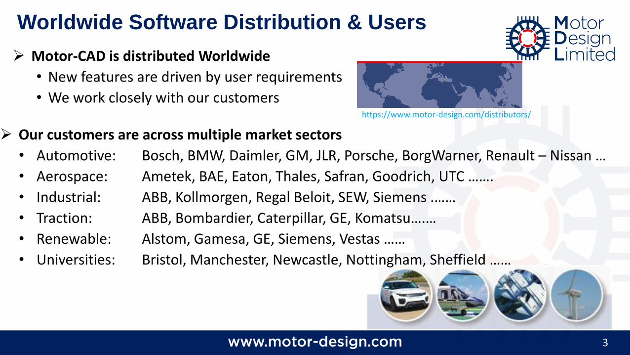
Worldwide Software Distribution & Users
➢ Our customers are across multiple market sectors
• Automotive: Bosch, BMW, Daimler, GM, JLR, Porsche, BorgWarner, Renault – Nissan …
• Aerospace: Ametek, BAE, Eaton, Thales, Safran, Goodrich, UTC …….
• Industrial: ABB, Kollmorgen, Regal Beloit, SEW, Siemens .……
• Traction: ABB, Bombardier, Caterpillar, GE, Komatsu….…
• Renewable: Alstom, Gamesa, GE, Siemens, Vestas ……
• Universities: Bristol, Manchester, Newcastle, Nottingham, Sheffield ……
➢ Motor-CAD is distributed Worldwide
• New features are driven by user requirements
• We work closely with our customershttps://www.motor-design.com/distributors/
4
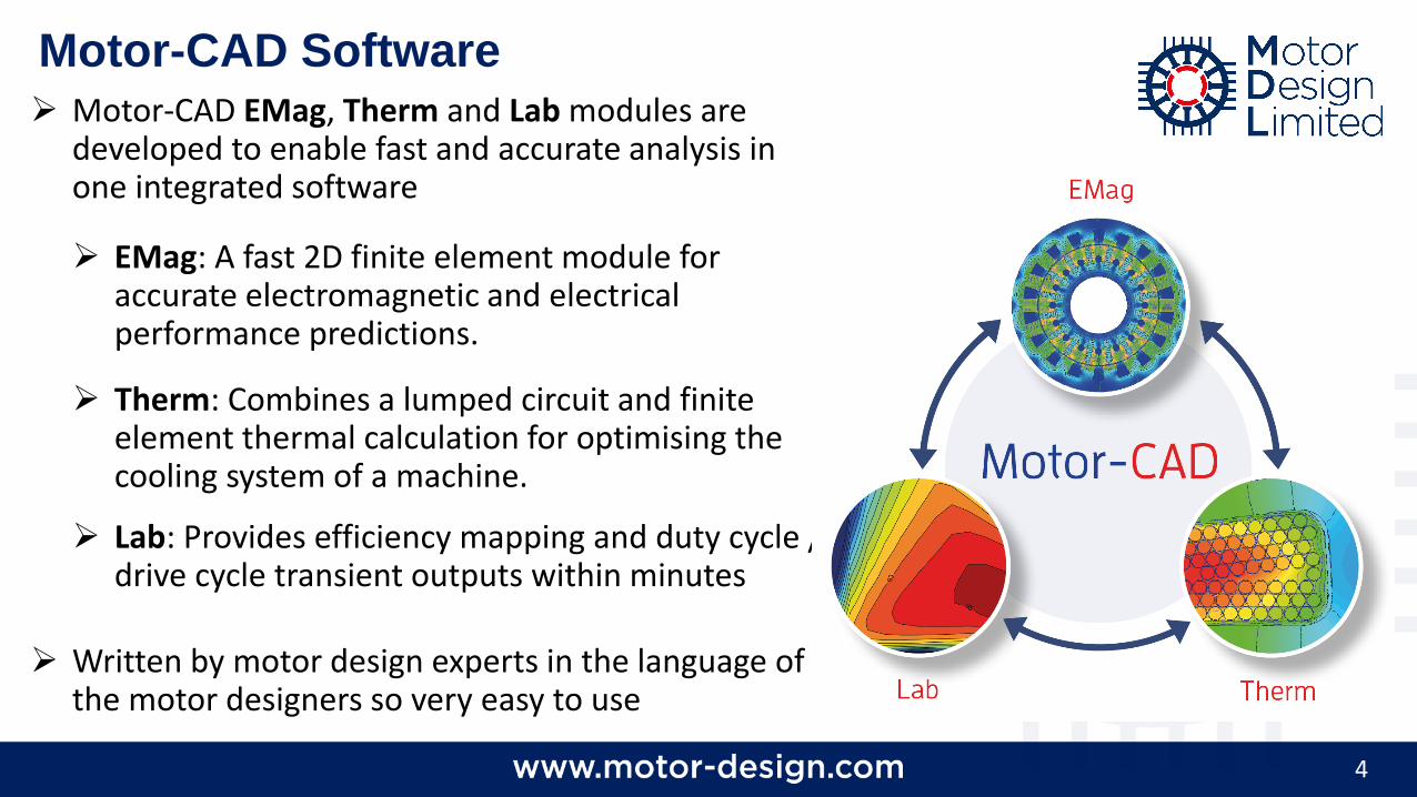
Motor-CAD Software➢ Motor-CAD EMag, Therm and Lab modules are
developed to enable fast and accurate analysis in one integrated software
➢ EMag: A fast 2D finite element module for accurate electromagnetic and electrical performance predictions.
➢ Therm: Combines a lumped circuit and finite element thermal calculation for optimising the cooling system of a machine.
➢ Lab: Provides efficiency mapping and duty cycle / drive cycle transient outputs within minutes
➢ Written by motor design experts in the language of the motor designers so very easy to use
5
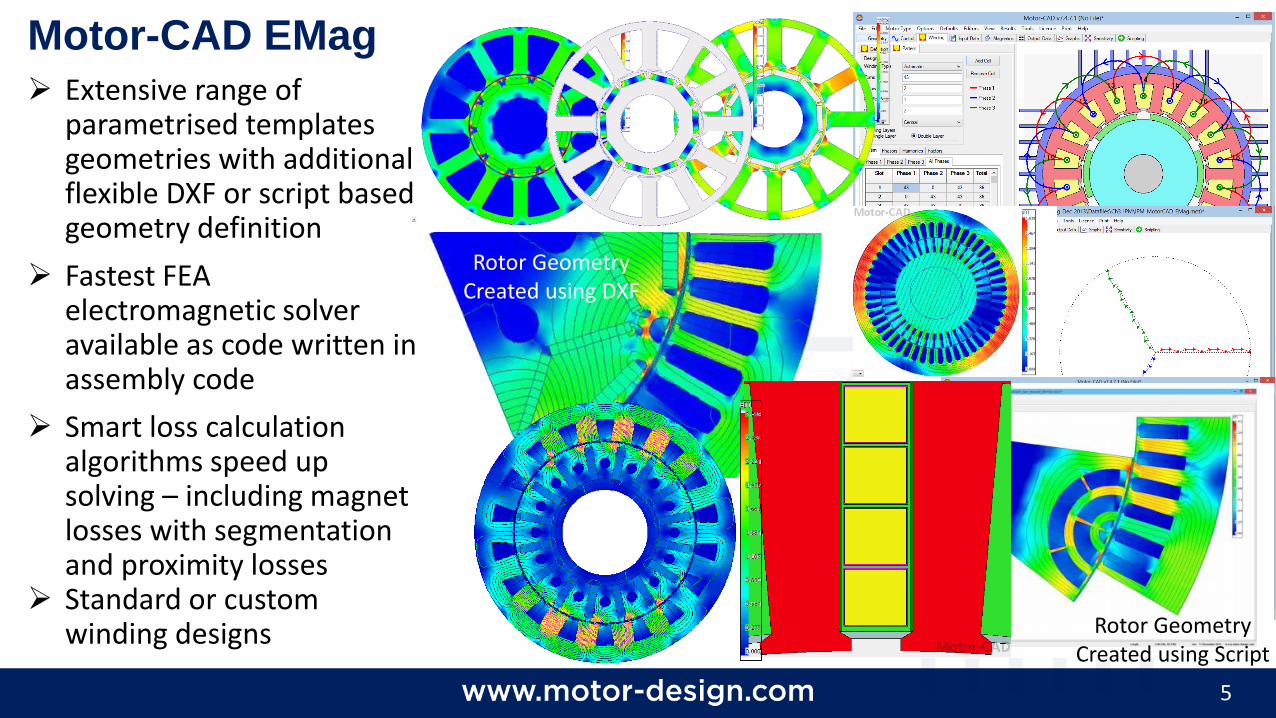
Motor-CAD EMag
➢ Extensive range of parametrised templates geometries with additional flexible DXF or script based geometry definition
➢ Fastest FEA electromagnetic solver available as code written in assembly code
➢ Smart loss calculation algorithms speed up solving – including magnet losses with segmentation and proximity losses
➢ Standard or custom winding designs Rotor Geometry
Created using Script
Rotor Geometry Created using DXF
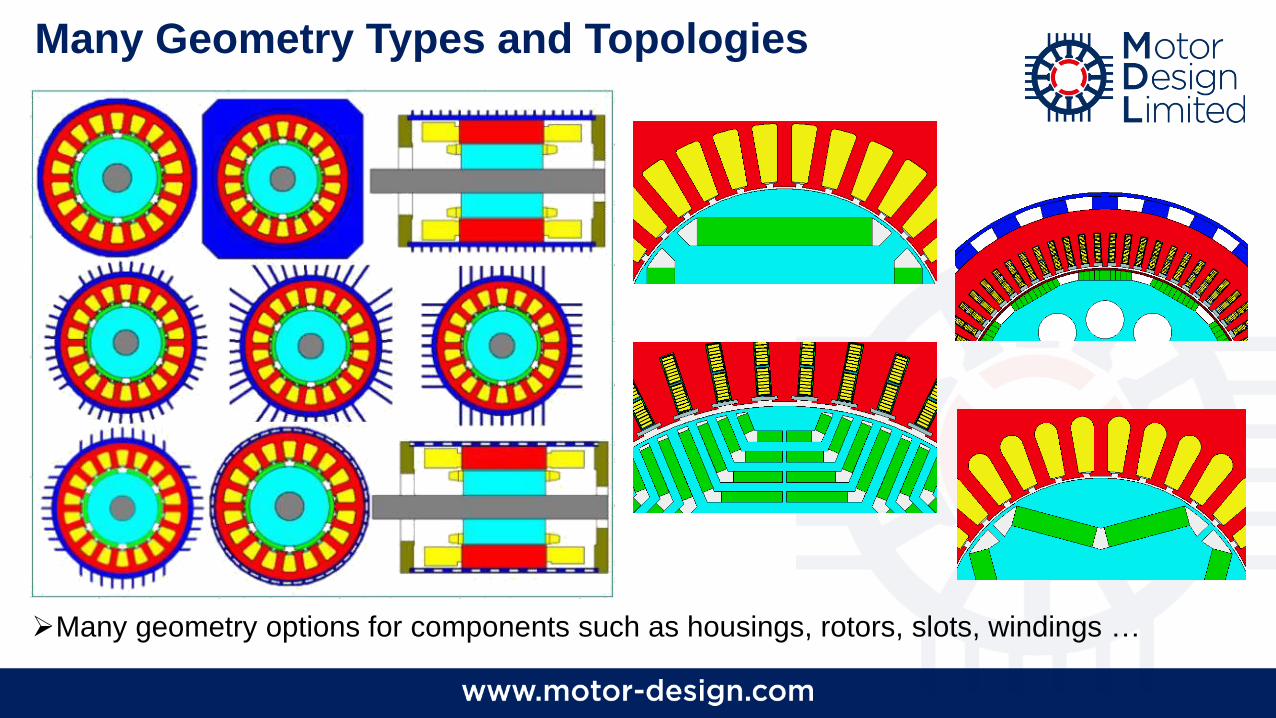
➢Many geometry options for components such as housings, rotors, slots, windings …
Many Geometry Types and Topologies
7
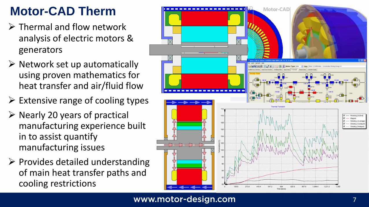
Motor-CAD Therm
➢ Thermal and flow network analysis of electric motors & generators
➢ Network set up automatically using proven mathematics for heat transfer and air/fluid flow
➢ Extensive range of cooling types
➢ Nearly 20 years of practical manufacturing experience built in to assist quantify manufacturing issues
➢ Provides detailed understanding of main heat transfer paths and cooling restrictions
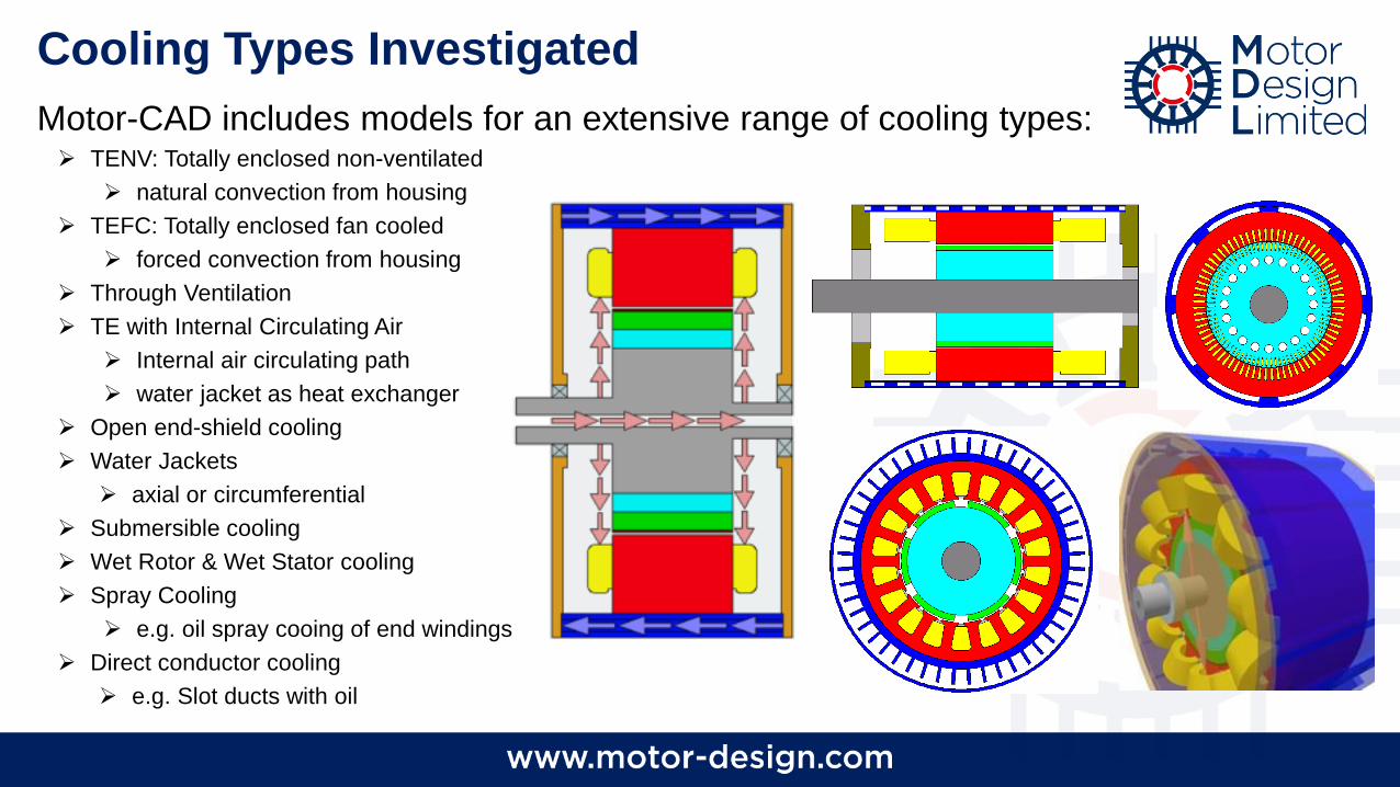
Cooling Types Investigated
Motor-CAD includes models for an extensive range of cooling types:➢ TENV: Totally enclosed non-ventilated
➢ natural convection from housing
➢ TEFC: Totally enclosed fan cooled
➢ forced convection from housing
➢ Through Ventilation
➢ TE with Internal Circulating Air
➢ Internal air circulating path
➢ water jacket as heat exchanger
➢ Open end-shield cooling
➢ Water Jackets
➢ axial or circumferential
➢ Submersible cooling
➢ Wet Rotor & Wet Stator cooling
➢ Spray Cooling
➢ e.g. oil spray cooing of end windings
➢ Direct conductor cooling
➢ e.g. Slot ducts with oil
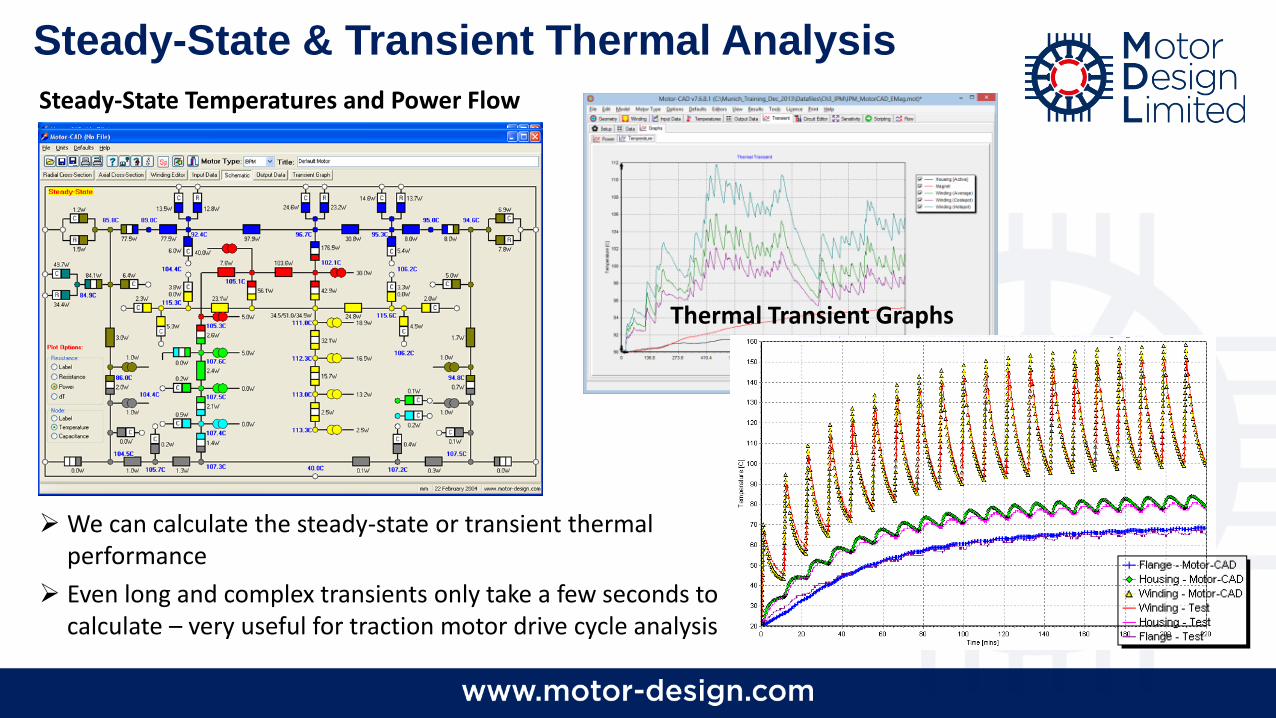
Steady-State & Transient Thermal Analysis
➢ We can calculate the steady-state or transient thermal performance
➢ Even long and complex transients only take a few seconds to calculate – very useful for traction motor drive cycle analysis
Thermal Transient Graphs
Steady-State Temperatures and Power Flow
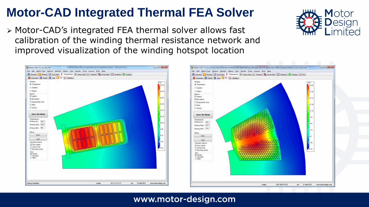
Motor-CAD Integrated Thermal FEA Solver
➢ Motor-CAD’s integrated FEA thermal solver allows fast calibration of the winding thermal resistance network and improved visualization of the winding hotspot location
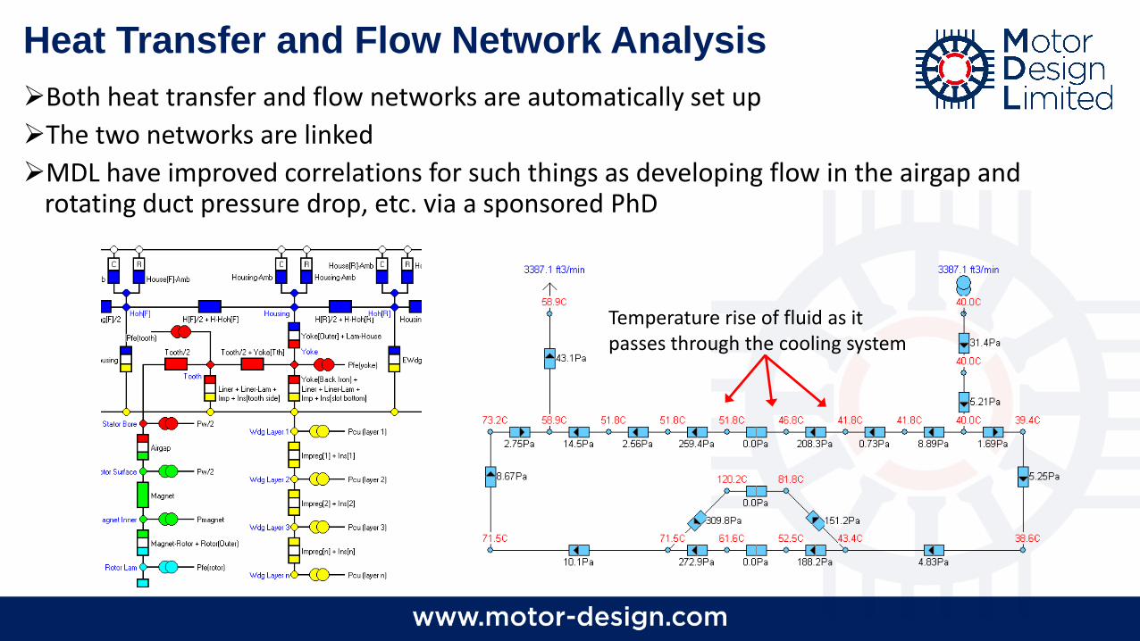
Heat Transfer and Flow Network Analysis
➢Both heat transfer and flow networks are automatically set up
➢The two networks are linked
➢MDL have improved correlations for such things as developing flow in the airgap and rotating duct pressure drop, etc. via a sponsored PhD
Temperature rise of fluid as it passes through the cooling system
12
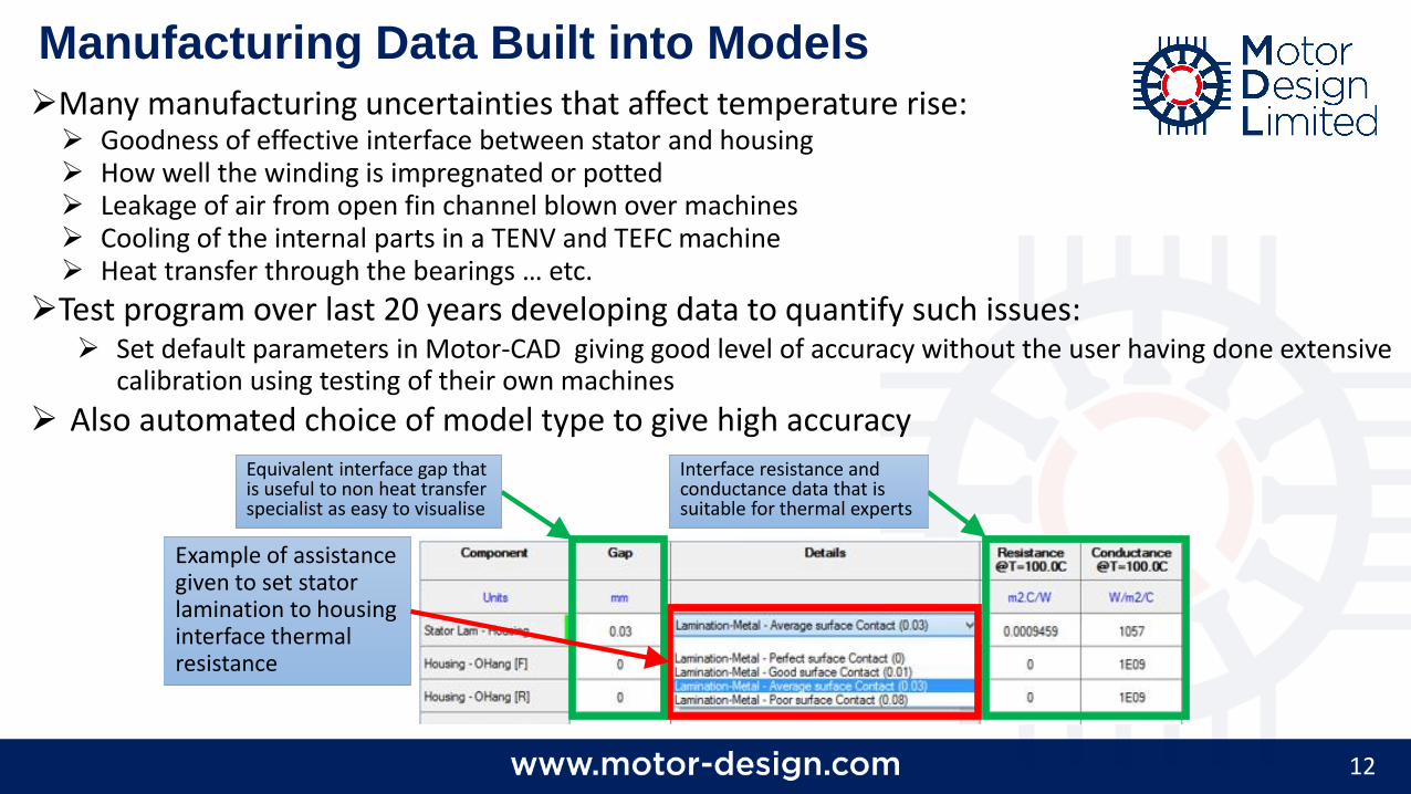
Manufacturing Data Built into Models
➢Many manufacturing uncertainties that affect temperature rise:➢ Goodness of effective interface between stator and housing➢ How well the winding is impregnated or potted ➢ Leakage of air from open fin channel blown over machines➢ Cooling of the internal parts in a TENV and TEFC machine➢ Heat transfer through the bearings … etc.
➢Test program over last 20 years developing data to quantify such issues:➢ Set default parameters in Motor-CAD giving good level of accuracy without the user having done extensive
calibration using testing of their own machines
➢ Also automated choice of model type to give high accuracy
Example of assistance given to set stator lamination to housing interface thermal resistance
Interface resistance and conductance data that is suitable for thermal experts
Equivalent interface gap that is useful to non heat transfer specialist as easy to visualise
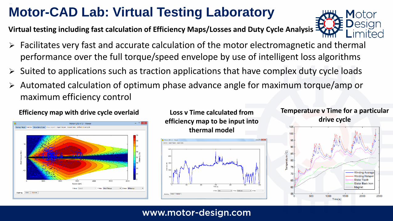
➢ Facilitates very fast and accurate calculation of the motor electromagnetic and thermal performance over the full torque/speed envelope by use of intelligent loss algorithms
➢ Suited to applications such as traction applications that have complex duty cycle loads
➢ Automated calculation of optimum phase advance angle for maximum torque/amp or maximum efficiency control
Motor-CAD Lab: Virtual Testing Laboratory
Efficiency map with drive cycle overlaid Loss v Time calculated from efficiency map to be input into
thermal model
Temperature v Time for a particular drive cycle
Virtual testing including fast calculation of Efficiency Maps/Losses and Duty Cycle Analysis
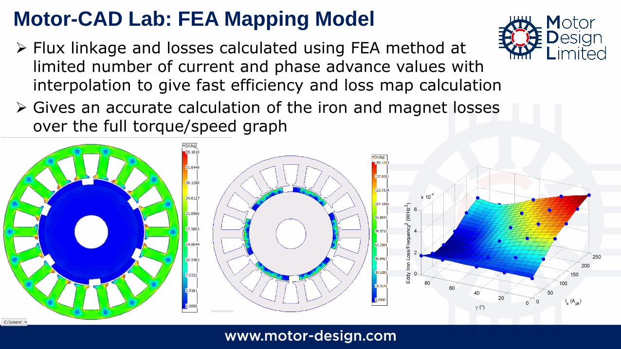
➢ Flux linkage and losses calculated using FEA method at limited number of current and phase advance values with interpolation to give fast efficiency and loss map calculation
➢ Gives an accurate calculation of the iron and magnet losses over the full torque/speed graph
Motor-CAD Lab: FEA Mapping Model
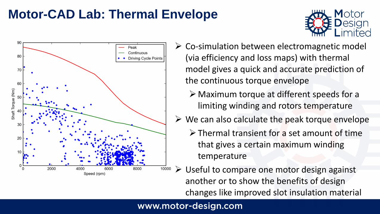
Motor-CAD Lab: Thermal Envelope
➢ Co-simulation between electromagnetic model (via efficiency and loss maps) with thermal model gives a quick and accurate prediction of the continuous torque envelope
➢Maximum torque at different speeds for a limiting winding and rotors temperature
➢ We can also calculate the peak torque envelope
➢Thermal transient for a set amount of time that gives a certain maximum winding temperature
➢ Useful to compare one motor design against another or to show the benefits of design changes like improved slot insulation material
16
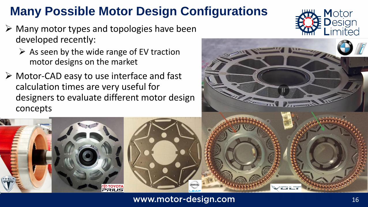
Many Possible Motor Design Configurations
➢ Many motor types and topologies have been developed recently:➢ As seen by the wide range of EV traction
motor designs on the market
➢ Motor-CAD easy to use interface and fast calculation times are very useful for designers to evaluate different motor design concepts

Motor-CAD Links to ANSYS Software
18
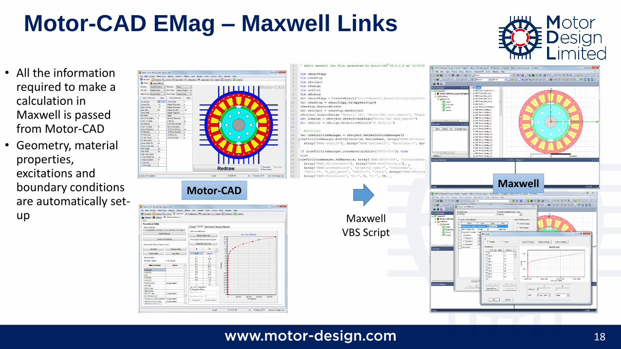
• All the information required to make a calculation in Maxwell is passed from Motor-CAD
• Geometry, material properties, excitations and boundary conditions are automatically set-up
Motor-CAD EMag – Maxwell Links
Motor-CAD
Maxwell VBS Script
Maxwell
19
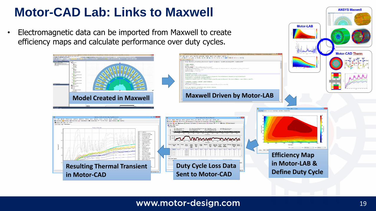
• Electromagnetic data can be imported from Maxwell to create efficiency maps and calculate performance over duty cycles.
Model Created in Maxwell Maxwell Driven by Motor-LAB
Efficiency Mapin Motor-LAB &Define Duty Cycle
Duty Cycle Loss DataSent to Motor-CAD
Resulting Thermal Transientin Motor-CAD
Motor-CAD Lab: Links to Maxwell
20
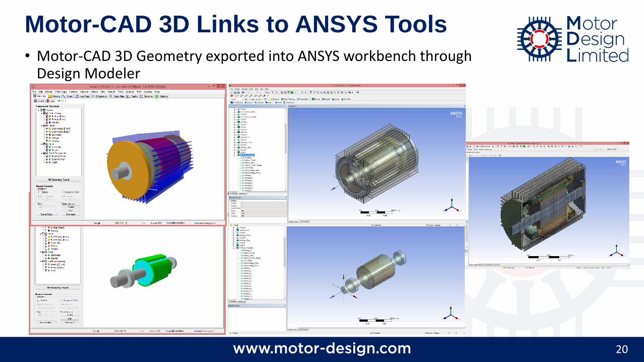
• Motor-CAD 3D Geometry exported into ANSYS workbench through Design Modeler
Motor-CAD 3D Links to ANSYS Tools
21
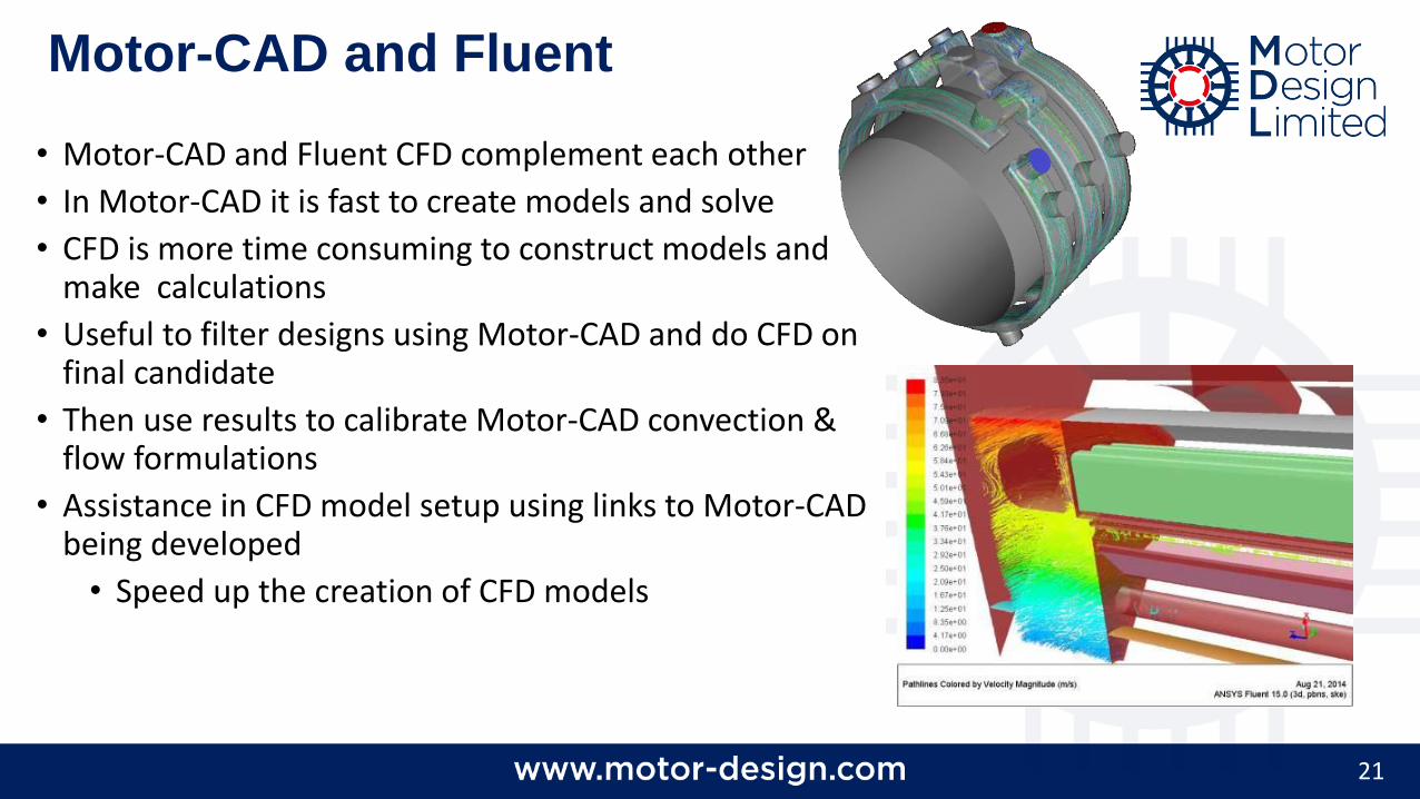
• Motor-CAD and Fluent CFD complement each other
• In Motor-CAD it is fast to create models and solve
• CFD is more time consuming to construct models and make calculations
• Useful to filter designs using Motor-CAD and do CFD on final candidate
• Then use results to calibrate Motor-CAD convection & flow formulations
• Assistance in CFD model setup using links to Motor-CAD being developed
• Speed up the creation of CFD models
Motor-CAD and Fluent
22
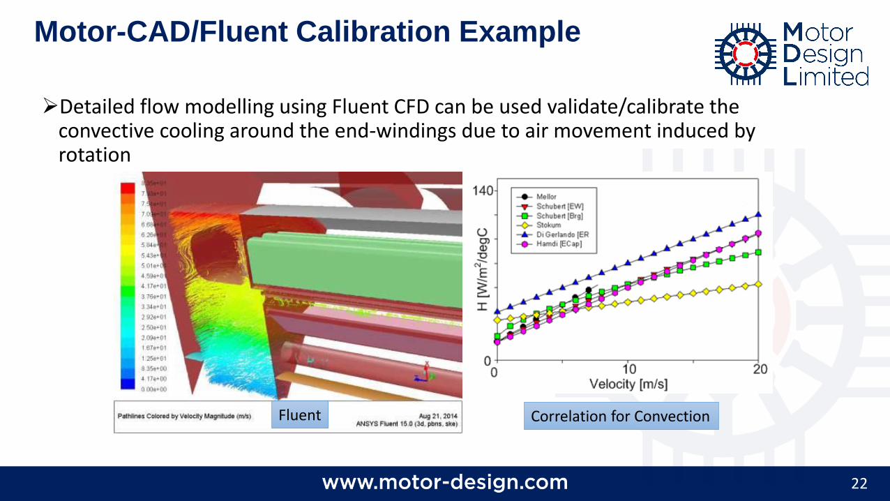
➢Detailed flow modelling using Fluent CFD can be used validate/calibrate the convective cooling around the end-windings due to air movement induced by rotation
Motor-CAD/Fluent Calibration Example
Fluent Correlation for Convection
23
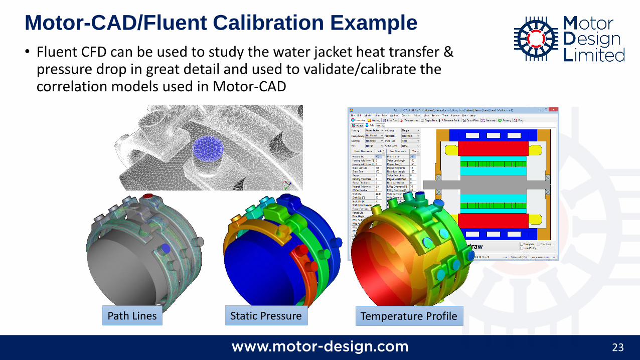
Path Lines Static Pressure
• Fluent CFD can be used to study the water jacket heat transfer & pressure drop in great detail and used to validate/calibrate the correlation models used in Motor-CAD
Motor-CAD/Fluent Calibration Example
Temperature Profile
24
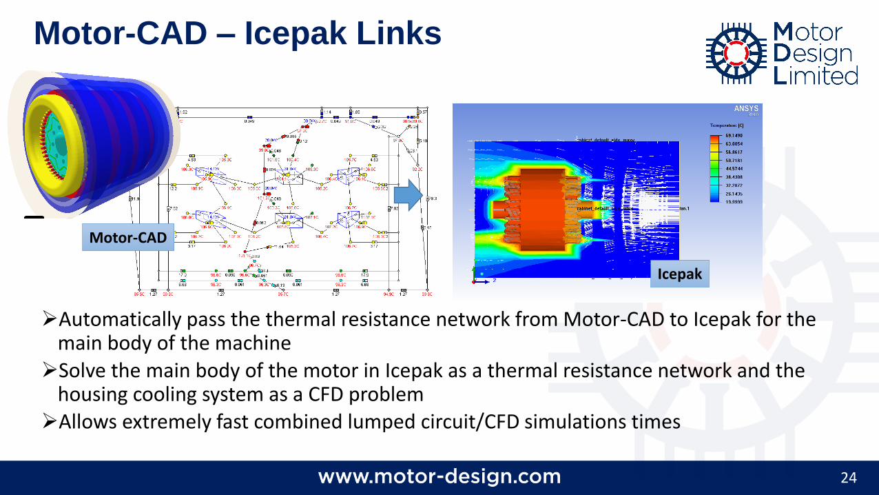
➢Automatically pass the thermal resistance network from Motor-CAD to Icepak for the main body of the machine
➢Solve the main body of the motor in Icepak as a thermal resistance network and the housing cooling system as a CFD problem
➢Allows extremely fast combined lumped circuit/CFD simulations times
Motor-CAD – Icepak Links
Motor-CAD
Icepak
25
ANSYS
MechanicalThermal/Stress
ANSYS CFD
Maxwell 2-D/3-DElectromagnetics
Design Modeler
Motor-CAD
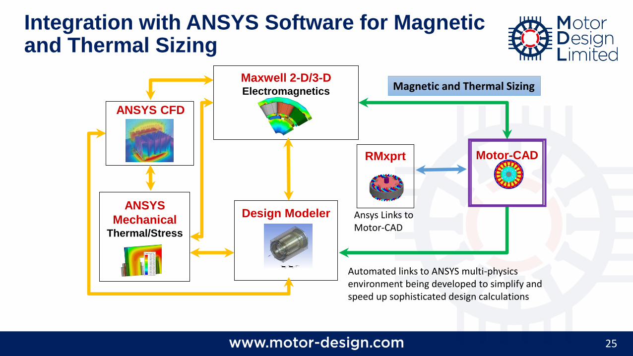
Automated links to ANSYS multi-physics environment being developed to simplify and speed up sophisticated design calculations
Magnetic and Thermal Sizing
Integration with ANSYS Software for Magnetic and Thermal Sizing
RMxprt
Ansys Links to Motor-CAD

Top Related