


Languages
Pages
Legal

MODELS SPK-280, SPK-500 & SPK-700
INSTRUCTION MANUAL
472 South Mill Street, Alamo TN 38001PHONE: 618-997-9348 - FAX: 618-993-5960SALES: 800-851-8180 - http://www.southern-pride.com - [email protected]: 800-437-2679 - SERVICE FAX: 618-993-0378 - parts&[email protected]
2
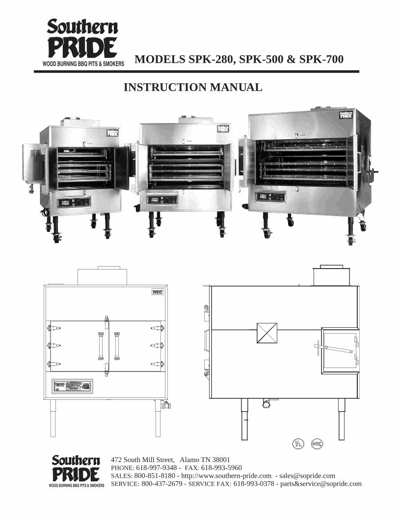
CONGRATULATIONS
In selecting Southern Pride, you have chosen the finest, most advancedand most fully automatic wood burning barbecue pit available.
With us, “ It’s Simply, a Matter of Pride”.
Please read this Instruction Manual carefully prior to installation and operationof your Southern Pride pit. Proper installation, operation, cleaning, and maintenance
are essential for your satisfaction and safe operation.
KEEP THIS MANNUAL FOR REFERENCE
TABLE OF CONTENTS
Safety Information . . . . . . . . . . . . . . . . . . . . . . . . . . . . . . . . . . . . . . . . . . . 3
Diagram of Controls & Components . . . . . . . . . . . . . . . . . . . . . . . . . . . . 4
Operating Instructions . . . . . . . . . . . . . . . . . . . . . . . . . . . . . . . . . . . . . . . 6
Cold Weather Operations . . . . . . . . . . . . . . . . . . . . . . . . . . . . . . . . . . . . . 11
Cleaning Instructions . . . . . . . . . . . . . . . . . . . . . . . . . . . . . . . . . . . . . . . . 12
Maintenance Schedule . . . . . . . . . . . . . . . . . . . . . . . . . . . . . . . . . . . . . . . 14
Electrical Instructions . . . . . . . . . . . . . . . . . . . . . . . . . . . . . . . . . . . . . . . 16
Burner Specification & Instructions . . . . . . . . . . . . . . . . . . . . . . . . . . . . 21
Replacement Parts List . . . . . . . . . . . . . . . . . . . . . . . . . . . . . . . . . . . . . . . 25
Venting Instructions . . . . . . . . . . . . . . . . . . . . . . . . . . . . . . . . . . . . . . . . . 23
Warranty . . . . . . . . . . . . . . . . . . . . . . . . . . . . . . . . . . . . . . . . . . . . . . . . . . 26
Gas Piping Instructions . . . . . . . . . . . . . . . . . . . . . . . . . . . . . . . . . . . . . . 22
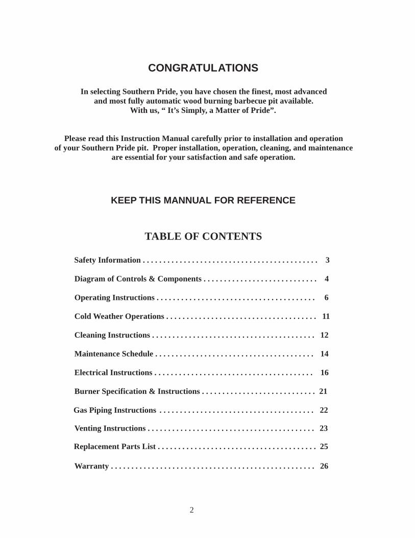
FOR YOUR SAFETY
IF YOU SMELL GAS . . .1. Open Windows.
2. Do not touch electrical switches. 3. Extinguish any open flames. 4. Immediately call your gas supplier.
DO NOT STORE OR USE GASOLINE OR OTHER FLAMMABLE VAPORS ORLIQUIDS IN THE VICINITY OF THIS OR ANY OTHER APPLIANCES.
SAFETY INFORMATION
1. The pit area MUST be kept clear and free of combustible materials, gasoline and other flammable vapors and liquids.
2. The flow of combustion and ventilating air MUST NOT be obstructed from reaching the pit.
3. The frame of the unit MUST be electrically grounded at all times. See “Electrical instructions”.
4. Caution should be used when opening and closing the Firebox Door. The door is HOTduring operation.
5. DO NOT remove service compartment access panels when unit is in operation or leave off during operation.
6. Gas burners require the services of an experienced mechanic for proper setting and adjustment. If the burner does not appear to be operating properly, DO NOT ATTEMPT TO ADJUST THE BURNER YOURSELF , but call in a competent serviceman or contact Southern Pride.
7. DO NOT allow unqualified personnel to perform service work or adjustments on this unit. To do so, will VOID WARRANTY and could result in a hazardous condition.
8. Be sure any new employees, who might operate the unit, are instructed on operation and safety information prior to operating the unit.
9. Caution: Ashes removed from the Firebox should be stored in a non-combustible container with a sealed lid only. Store ashes in a well ventilated area. FUMES COULD BE HAZARDOUS.
10. WARNING: IT IS EXTREMELY IMPORTANT TO FOLLOW DAILY CLEANING INSTRUCTIONS. GREASE OR SOLIDS BUILDUP INSIDE THE PIT COULD RESULT IN A FIRE HAZARD.
11. KEEP THIS INSTRUCTION MANUAL FOR REFERENCE.
3
OFF ON
M
AIN P O WER
RO
TI
SSERIE ADVANCE
SM
OKE EXTRACTOR
CIR
C
UIT B R EAK
ER
SOUTHERN PRIDE’SK-SERIES BBQ OVEN
4
112
2
4
10 11
STANDARD CONTROLS
15
6
9
5
13
14
7
8
3
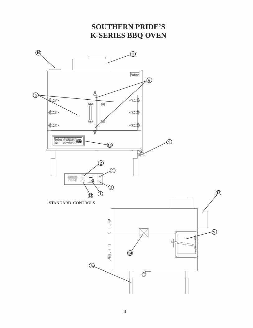
SPK-700, SPK-500, & SPK-280CONTROLS AND COMPONENTS
1. CV CONTROL THERMOSTAT - Adjustable temperature setting (140-325° F) with OFF position. Maintains desired Pit temperature by controlling the Gas Burner. It also displays the actual temperature inside the oven during the cook cycle.
2. MAIN POWER SWITCH - Activates the Rotisserie, Convection Fan, Thermostat, and Red Indicator Lamp. (The Red Indicator Lamp on the Main Power Switch indicates when the switch is ON.)
3. OPTIONAL SMOKE EXTRACTOR SWITCH - Activates Smoke Extractor Damper, Exhaust Fan, and Blue Indicator Lamp. (The Blue Indicator Lamp on the Smoke Extractor Switch indicates when the switch is ON.) At the same time it de-activates the Burner and Red Indicator Lamp.
4. CIRCUIT BREAKER - Provides protection for the Rotisserie Drive Motor.
5. MEAT LOADING DOORS - For access to Racks and Pit interior.
6. MEAT LOADING DOOR LATCHES - Latches apply positive pressure and seals doors.
7. FIREBOX DOOR - Provides access for loading of wood in the Firebox Chamber.
8. CABINET LEGS - Provides adjustment for leveling of the unit.
9. DRAIN VALVE - Is opened after each cooking to drain grease.
10. FLUE COLLAR - For connection of 6” Flue.
11. OPTIONAL SMOKE EXTRACTOR DAMPER - Closes to hold smoke inside pit while cook- ing and opens for Exhaust Fan to remove smoke when Smoke Extractor Switch is ON or when Meat Loading Doors are Open.
12. ROTISSERIE ADVANCE SWITCH - Momentarily activates Rotisserie to advance the food racks for loading and unloading when the Meat Door is open, or the Main Power switch is OFF.
13. CONVECTION FAN - Provides air flow inside the Oven for even cooking.
14. BEARING COVER - Provides access for Bearing.
15. DIGITAL CONTROL (Optional) - Provides precise control of the oven and adds special features, such as a Hold Mode, Automatic Cool Down prior to advancing into the Hold Mode and an Audible Alarm that sounds when the Cook Cycle is complete or when the control advances to the Hold Mode.
5
6
OPERATING INSTRUCTIONS
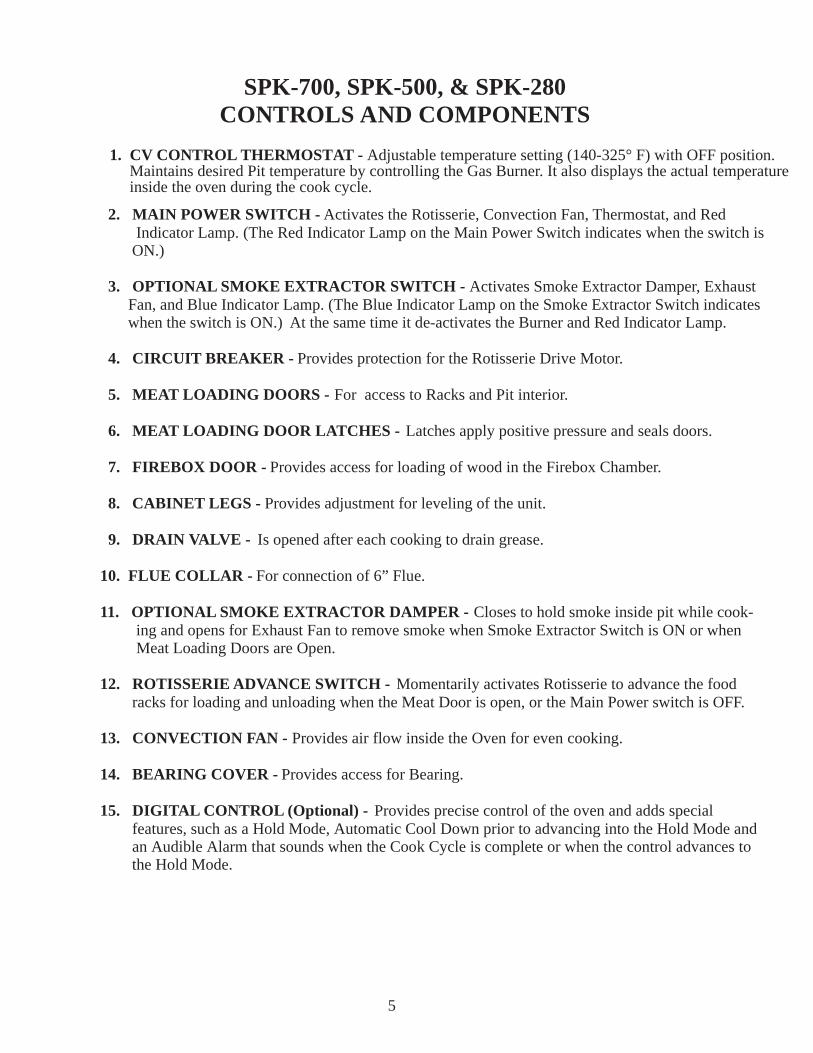
1. Load meat on the food racks. DO NOT LET THE MEAT EXTEND BEYOND ORHANG OVER THE EDGE OF THE RACKS.
CORRECT INCORRECT Load meat on bottom rack first. May cause food to tip and meat to fall. This could cause the Rotisserie to jam.
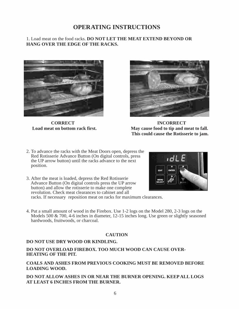
2. To advance the racks with the Meat Doors open, depress the Red Rotisserie Advance Button (On digital controls, press the UP arrow button) until the racks advance to the next position.
3. After the meat is loaded, depress the Red Rotisserie Advance Button (On digital controls press the UP arrow button) and allow the rotisserie to make one complete revolution. Check meat clearances to cabinet and all racks. If necessary reposition meat on racks for maximum clearances.
4. Put a small amount of wood in the Firebox. Use 1-2 logs on the Model 280, 2-3 logs on the Models 500 & 700, 4-6 inches in diameter, 12-15 inches long. Use green or slightly seasoned hardwoods, fruitwoods, or charcoal.
CAUTION
DO NOT USE DRY WOOD OR KINDLING.
DO NOT OVERLOAD FIREBOX. TOO MUCH WOOD CAN CAUSE OVER-HEATING OF THE PIT.
COALS AND ASHES FROM PREVIOUS COOKING MUST BE REMOVED BEFORELOADING WOOD.
DO NOT ALLOW ASHES IN OR NEAR THE BURNER OPENING. KEEP ALL LOGSAT LEAST 6 INCHES FROM THE BURNER.
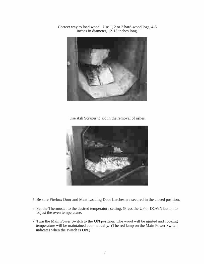
Correct way to load wood. Use 1, 2 or 3 hard-wood logs, 4-6inches in diameter, 12-15 inches long.
Use Ash Scraper to aid in the removal of ashes.
5. Be sure Firebox Door and Meat Loading Door Latches are secured in the closed position.
6. Set the Thermostat to the desired temperature setting. (Press the UP or DOWN button to adjust the oven temperature.
7. Turn the Main Power Switch to the ON position. The wood will be ignited and cookingtemperature will be maintained automatically. (The red lamp on the Main Power Switchindicates when the switch is ON.)
7
8. To check or unload meat, on units with optional Smoke Extractor Switch; depress and hold the Smoke Extractor Switch to turn it ON (The blue lamp on the Smoke Extractor Switch indicates when the switch is ON), for 20 seconds prior to opening the Meat Loading Doors.
CAUTION: ON OVENS EQUIPPED WITH STANDARD CONTROLS BE SURE THAT THE SMOKE EXTRACTOR SWITCH IS OFF DURING THE COOKING PROCESS.
9. When the meat is cooked; on digital control models press and hold the start / stop button until idle appears in the LED, or on ovens with standard controls turn the Main Power Switch to the OFF position. On models with optional Smoke Extractor, with digital
standard controls, depress and hold the Smoke Extractor Switch to turn it ON (The blue lamp on the Smoke Extractor Switch indicates when the switch is ON), for 20 seconds prior to opening the Meat Loading Doors. To unload racks, on ovens with digital controls press the up button to advance the rotisserie, or on an oven with standard controls depress the Rotisserie Advance Button until the racks advance to an unloading position.
controls, press the down button to activate the smoke extractor, or on units with
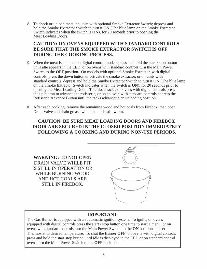
10. After each cooking, remove the remaining wood and hot coals from Firebox, then open Drain Valve and drain grease while the pit is still warm.
CAUTION: BE SURE MEAT LOADING DOORS AND FIREBOX DOOR ARE SECURED IN THE CLOSED POSITION IMMEDIATELY
FOLLOWING A COOKING AND DURING NON-USE PERIODS.
IMPORTANTThe Gas Burner is equipped with an automatic ignition system. To ignite; on ovens equipped with digital controls press the start / stop button one time to start a menu, or on ovens with standard controls turn the Main Power Switch to the ON position and set Thermostat to desired temperature. To shut the Burner OFF, on ovens with digital controls press and hold the start stop button until idle is displayed in the LED or on standard control ovens,turn the Main Power Switch to the OFF position.
8
WARNING: DO NOT OPENDRAIN VALVE WHILE PIT
IS STILL IN OPERATION ORWHILE BURNING WOOD
AND HOT COALS ARESTILL IN FIREBOX.

9
Programming a Menu with Optional Digital Controls
The menu consists of a cook temperature, cook time, and choice of having the control advanceto a hold mode after the cook time has elapsed or end the menu when the cook time has elapsed.
• Control must be in the “IDLE” mode, if the control is “OFF” a press of any button will bring the control back to “IDLE”.
• PRESS the cook temp button, (tEnP 1 will appear in the LED display): PRESS the up/down buttons to obtain the desired cook temperature.
• PRESS the cook time button, (tinE1 will appear in the LED display): PRESS the up/down buttons to obtain the desired cook time.
• Press the hold temp. button, (HtEnp will appear in the LED display): PRESS the up/ down buttons to obtain the desired hold temp., if a hold temp. is not desired: PRESS the down button until “OFF” is displayed in the LED.
• Programming the menu is complete: To start the menu, PRESS the start/stop button one time. The control will begin the menu.
• To pause the menu PRESS the start/stop button one time, to resume the menu, PRESS the start/stop button again.
• To cancel or stop the menu, PRESS and hold the start/stop button until “IDLE” is displayed in the LED.
When the cook cycle is complete there are two possible actions that can be taken. One is if ahold temperature was programmed into the menu, the control will momentarily sound an audiblealarm, the smoke extractor will be automatically activated, for a period of five minutes, to bringthe oven temperature down closer to the programmed hold temperature. Then, “HOLD” andthe length of time the control has been in the hold mode will alternately flash in the LED display.The control will maintain the hold temperature until the start/stop button is depressed to “END”the menu, and bring the control to the “IDLE” mode. If the hold temperature was programmedto “OFF” then “END” will be displayed on the LED display, and an audible alarm will soundcontinuously until the start/stop button is depressed, to “END” the menu, and bring the controlto the “IDLE” mode.
Programming a Menu with Standard Controls
• After the product has been loaded into the oven and the meat loading doors have been closed, and logs placed in the firebox and the firebox door closed turn the oven power switch on. The themostat control on the oven will either come on to the last temperature used or be off.
• Using the up/down button on the controller set the desired temperature setting. Once the oven starts the LED display will show the actual internal temperature of the oven, you can toggle to the set temperature by pressing either up/down button.

10
Programming a Menu with Optional Digital Controls Cont.
• The control should be in the “IDLE” mode. (The burner, convection fan, and the rotisserie will be off)
• When the menu is in progress a PRESS of the down arrow button will activate the smoke extractor, prior to opening the meat doors, if the doors are not opened the smoke extractor will go off after one minute and the menu will resume. If the doors are opened the menu will resume when the doors are closed. The smoke extractor will automatically activate when the doors are opened, and the menu will resume again when the doors are closed.
• When the doors are open a PRESS of the up arrow button will advance the rotisserie. If the oven is equipped with an optional rotisserie advance foot switch, a PRESS of the foot pedal will advance the rotisserie when the meat doors are open too.
• Unload the meat from the racks, using the rotisserie advance button to rotate the racks.
• After each cook cycle, remove the remaining wood and coals from the firebox, then open the drain valve and drain the grease while the oven is still warm.
• After the control has been in the “IDLE” mode for five minutes it will go to “OFF”, a PRESS of any button will bring the control back to “IDLE”.
CAUTION: BE SURE THE MEAT LOADING DOORS ANDTHE FIREBOX DOOR ARE SECURED IN THE CLOSEDPOSITION IMMEDIATELY FOLLOWING A COOKING,
AND DURING NON-USE PERIODS.
WARNING: DO NOT OPENDRAIN VALVE WHILE PIT
IS STILL IN OPERATION, ORWHILE BURNING WOOD
AND HOT COALS ARE STILLIN THE FIREBOX.
SMOKER OVEN COLD WEATHER OPERATIONS
When temperatures drop below freezing there are issues that may develop. Listed below aresome of those issues and ways to correct or reduce the effects of the problem.
1. Cold weather thickens the gearbox oil and at times it will cause the circuit breaker onthe control panel to trip. There are several things that can be done during these coldweather conditions.
a. A preventative measure would be to keep rotisserie system rotatingwith thermostat at the lowest temperature setting.
b: If the circuit breaker has already tripped, you may be able to warm thegear box and oil up by letting the burner come on at the highest temp setting.Continue to warm the oven for 45-60 min and reset the panel circuit breakerby pushing in the center button on breaker.
Warning: Allowing the panel circuit breaker to continually trip will eventually weaken the breaker so that it will trip at a level below the designed specification.
2. Grease in oven drain solidifies in cold weather. Listed below are things that can bedone to reduce, or correct the effects of this problem.
a. Drain the oven after every cooking to purge the drainpipe of liquids beforethey solidify. In extreme cold weather conditions customers have hadsuccess wrapping the drainpipe with electric heat tape and insulating heattape and pipe.
3. LED Displays an error 7
a. Ovens with digital controllers are effected by cold weather particularlywhen the oven is outside or when it a through the wall installation. Thiserror typically only happens when the oven has not been used for a significantduration of time that allowed the oven to become extremely cold usuallytemperatures below 32F. The following action will generally clear the error7 code
b. Hold a cloth under warm water and wring water out, hold warm rag againsttop of the thermocouple on the inside of oven (left front corner) for about20-30 seconds. Remove rag and close door and start oven.
11
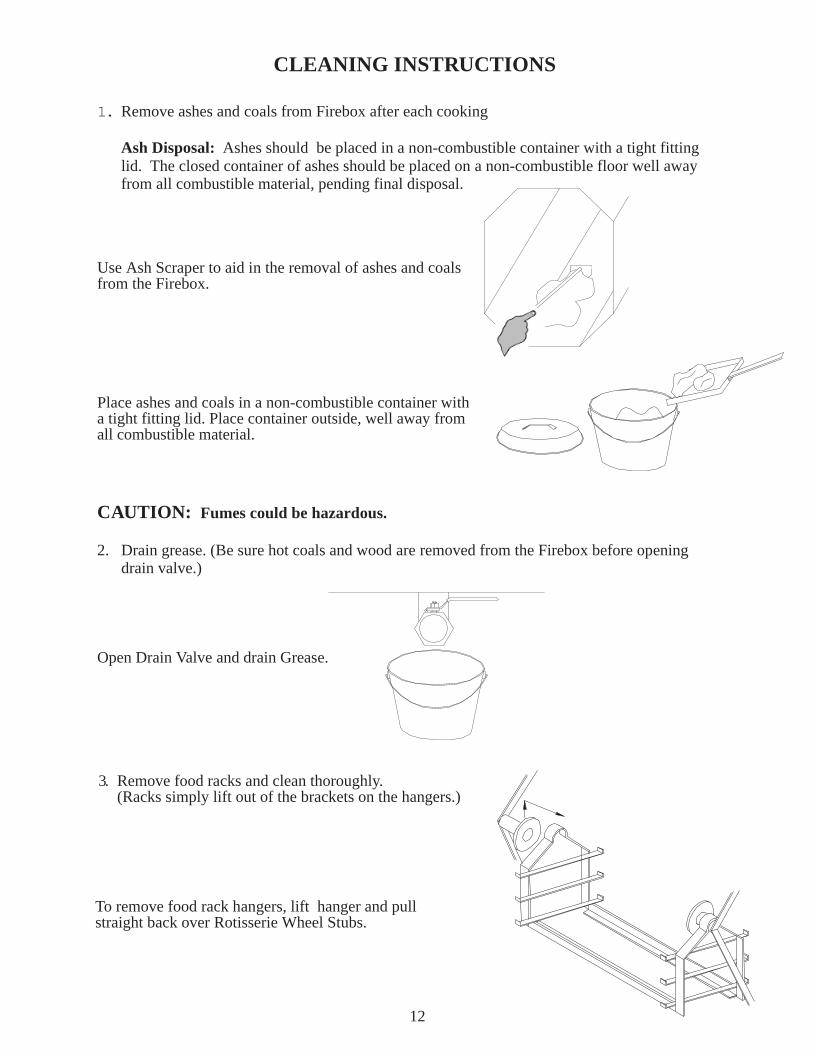
1. Remove ashes and coals from Firebox after each cooking
Ash Disposal: Ashes should be placed in a non-combustible container with a tight fitting lid. The closed container of ashes should be placed on a non-combustible floor well away from all combustible material, pending final disposal.
Use Ash Scraper to aid in the removal of ashes and coalsfrom the Firebox.
Place ashes and coals in a non-combustible container witha tight fitting lid. Place container outside, well away fromall combustible material.
CAUTION: Fumes could be hazardous.
2. Drain grease. (Be sure hot coals and wood are removed from the Firebox before opening drain valve.)
Open Drain Valve and drain Grease.
CLEANING INSTRUCTIONS
12
3. Remove food racks and clean thoroughly.(Racks simply lift out of the brackets on the hangers.)
To remove food rack hangers, lift hanger and pullstraight back over Rotisserie Wheel Stubs.
4. Thoroughly clean complete interior of pit. Use food service degreaser. Spray degreaser on the interior of the pit and allow to set for 5-10 minutes. Rinse thoroughly with water hose or pressure washer. Drain through Drain Valve.
WARNING
IT IS EXTREMELY IMPORTANT TO FOLLOW THE ABOVE DAILY CLEANING PROCEDURES. GREASE OR SOLIDS BUILDUP INSIDE THE PIT COULD RESULT IN A FIRE HAZARD.
13
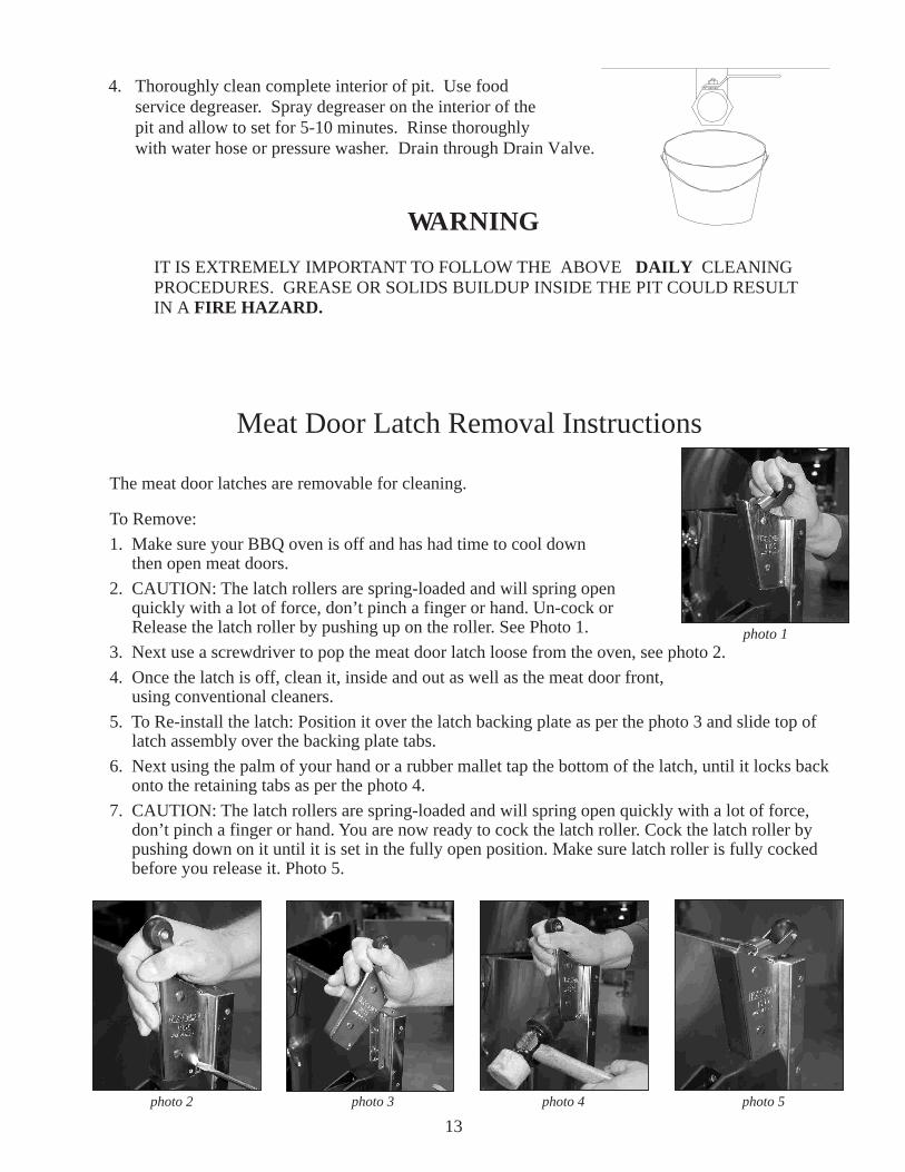
Meat Door Latch Removal Instructions
The meat door latches are removable for cleaning.
To Remove:
1. Make sure your BBQ oven is off and has had time to cool down then open meat doors.
2. CAUTION: The latch rollers are spring-loaded and will spring open quickly with a lot of force, don’t pinch a finger or hand. Un-cock or Release the latch roller by pushing up on the roller. See Photo 1.
3. Next use a screwdriver to pop the meat door latch loose from the oven, see photo 2.
4. Once the latch is off, clean it, inside and out as well as the meat door front, using conventional cleaners.
5. To Re-install the latch: Position it over the latch backing plate as per the photo 3 and slide top of latch assembly over the backing plate tabs.
6. Next using the palm of your hand or a rubber mallet tap the bottom of the latch, until it locks back onto the retaining tabs as per the photo 4.
7. CAUTION: The latch rollers are spring-loaded and will spring open quickly with a lot of force, don’t pinch a finger or hand. You are now ready to cock the latch roller. Cock the latch roller by pushing down on it until it is set in the fully open position. Make sure latch roller is fully cocked before you release it. Photo 5.
photo 1
photo 2 photo 3 photo 4 photo 5
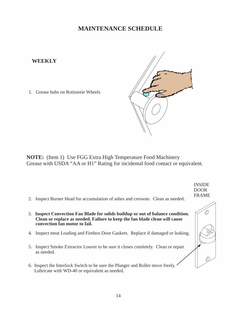
MAINTENANCE SCHEDULE
WEEKLY
1. Grease hubs on Rotisserie Wheels
NOTE: (Item 1) Use FGG Extra High Temperature Food MachineryGrease with USDA “AA or H1” Rating for incidental food contact or equivalent.
2. Inspect Burner Head for accumulation of ashes and creosote. Clean as needed.
3. Inspect Convection Fan Blade for solids buildup or out of balance condition. Clean or replace as needed. Failure to keep the fan blade clean will cause convection fan motor to fail.
4. Inspect meat Loading and Firebox Door Gaskets. Replace if damaged or leaking.
5. Inspect Smoke Extractor Louver to be sure it closes comletely. Clean or repair as needed.
6. Inspect the Interlock Switch to be sure the Plunger and Roller move freely. Lubricate with WD-40 or equivalent as needed.
14
INSIDEDOORFRAME
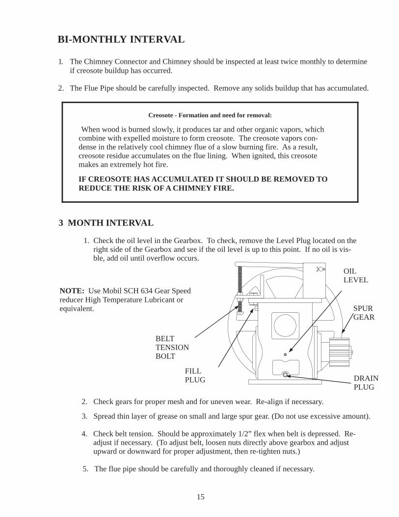
BI-MONTHLY INTERVAL
1. The Chimney Connector and Chimney should be inspected at least twice monthly to determine if creosote buildup has occurred.
2. The Flue Pipe should be carefully inspected. Remove any solids buildup that has accumulated.
1. Check the oil level in the Gearbox. To check, remove the Level Plug located on the right side of the Gearbox and see if the oil level is up to this point. If no oil is vis- ble, add oil until overflow occurs.
2. Check gears for proper mesh and for uneven wear. Re-align if necessary.
3. Spread thin layer of grease on small and large spur gear. (Do not use excessive amount).
4. Check belt tension. Should be approximately 1/2” flex when belt is depressed. Re- adjust if necessary. (To adjust belt, loosen nuts directly above gearbox and adjust upward or downward for proper adjustment, then re-tighten nuts.)
5. The flue pipe should be carefully and thoroughly cleaned if necessary.
3 MONTH INTERVAL
NOTE: Use Mobil SCH 634 Gear Speedreducer High Temperature Lubricant orequivalent.
15
OILLEVEL
DRAINPLUG
FILLPLUG
BELTTENSIONBOLT
SPURGEAR
Creosote - Formation and need for removal:
When wood is burned slowly, it produces tar and other organic vapors, which combine with expelled moisture to form creosote. The creosote vapors con- dense in the relatively cool chimney flue of a slow burning fire. As a result, creosote residue accumulates on the flue lining. When ignited, this creosote makes an extremely hot fire.
IF CREOSOTE HAS ACCUMULATED IT SHOULD BE REMOVED TO REDUCE THE RISK OF A CHIMNEY FIRE.
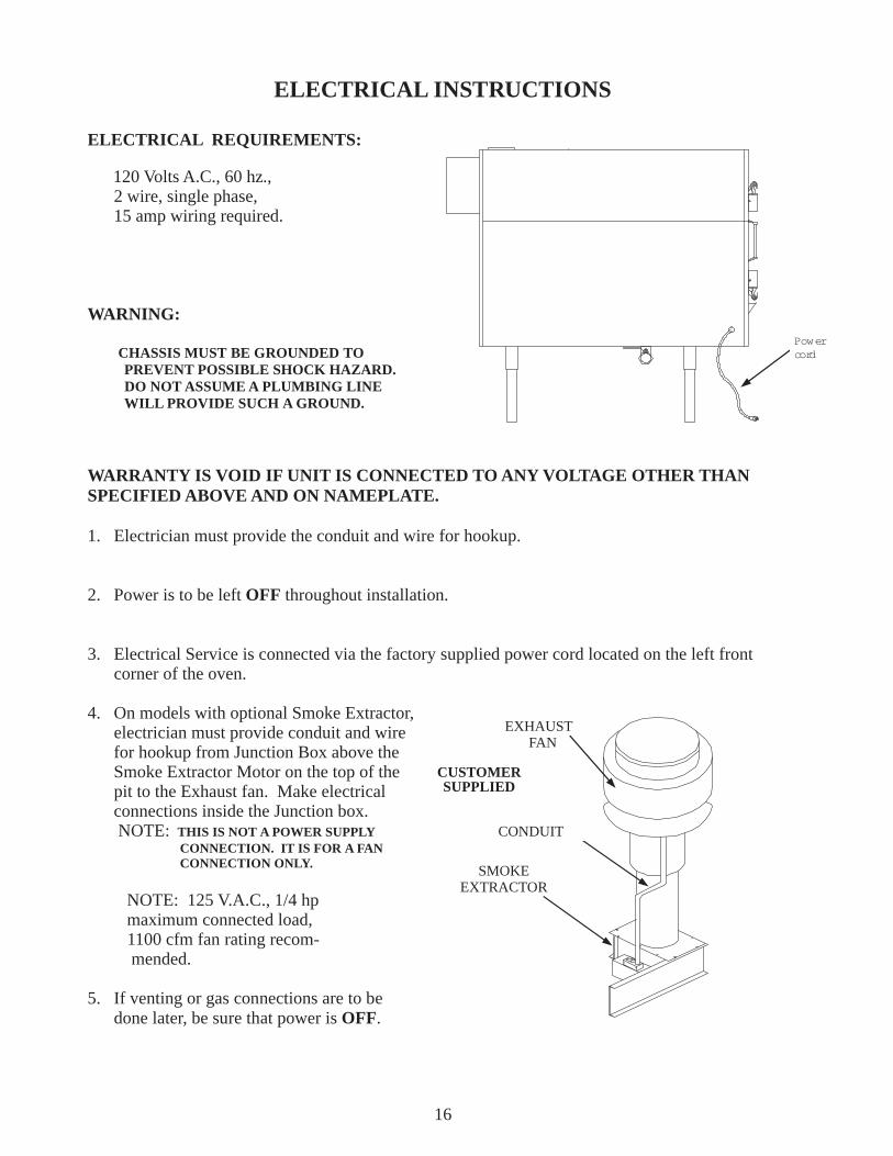
ELECTRICAL INSTRUCTIONS
ELECTRICAL REQUIREMENTS:
120 Volts A.C., 60 hz., 2 wire, single phase, 15 amp wiring required.
WARNING:
CHASSIS MUST BE GROUNDED TO PREVENT POSSIBLE SHOCK HAZARD. DO NOT ASSUME A PLUMBING LINE WILL PROVIDE SUCH A GROUND.
WARRANTY IS VOID IF UNIT IS CONNECTED TO ANY VOLTAGE OTHER THANSPECIFIED ABOVE AND ON NAMEPLATE.
1. Electrician must provide the conduit and wire for hookup.
2. Power is to be left OFF throughout installation.
3. Electrical Service is connected via the factory supplied power cord located on the left front corner of the oven.
4. On models with optional Smoke Extractor, electrician must provide conduit and wire for hookup from Junction Box above the Smoke Extractor Motor on the top of the pit to the Exhaust fan. Make electrical connections inside the Junction box. NOTE: THIS IS NOT A POWER SUPPLY CONNECTION. IT IS FOR A FAN CONNECTION ONLY.
NOTE: 125 V.A.C., 1/4 hp maximum connected load, 1100 cfm fan rating recom- mended.
5. If venting or gas connections are to be done later, be sure that power is OFF.
16
EXHAUSTFAN
CONDUIT
SMOKEEXTRACTOR
Powercord
CUSTOMERSUPPLIED
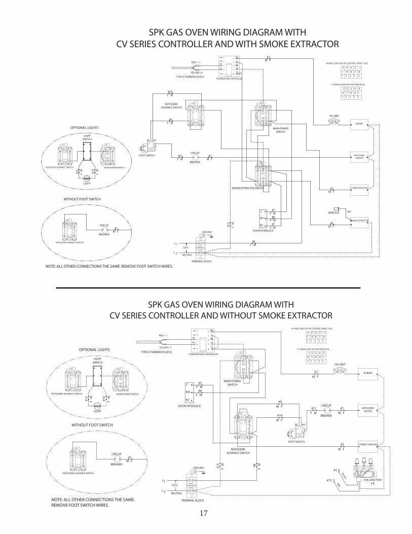
17
18
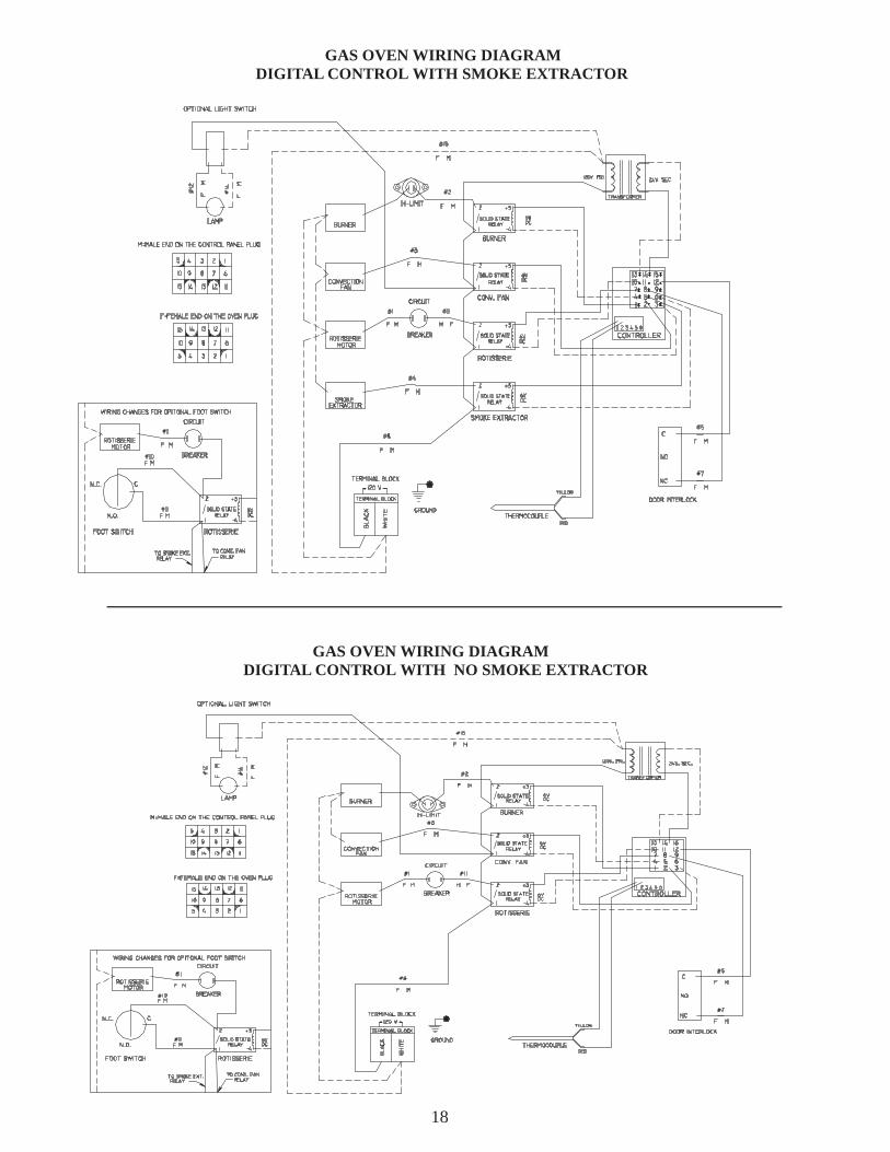
GAS OVEN WIRING DIAGRAMDIGITAL CONTROL WITH NO SMOKE EXTRACTOR
GAS OVEN WIRING DIAGRAMDIGITAL CONTROL WITH SMOKE EXTRACTOR
19
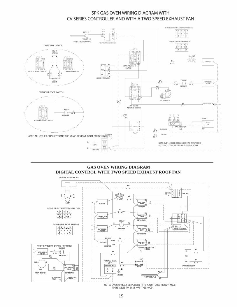
GAS OVEN WIRING DIAGRAMDIGITAL CONTROL WITH TWO SPEED EXHAUST ROOF FAN
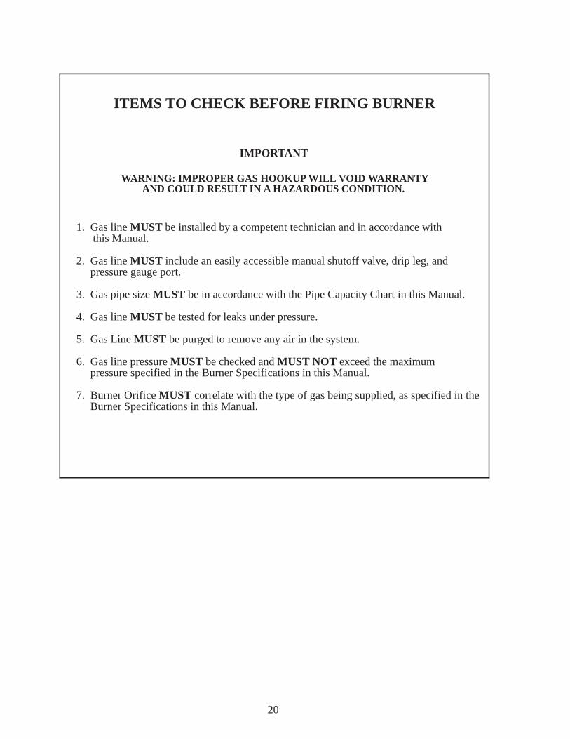
ITEMS TO CHECK BEFORE FIRING BURNER
IMPORTANT
WARNING: IMPROPER GAS HOOKUP WILL VOID WARRANTYAND COULD RESULT IN A HAZARDOUS CONDITION.
1. Gas line MUST be installed by a competent technician and in accordance with this Manual.
2. Gas line MUST include an easily accessible manual shutoff valve, drip leg, and pressure gauge port.
3. Gas pipe size MUST be in accordance with the Pipe Capacity Chart in this Manual.
4. Gas line MUST be tested for leaks under pressure.
5. Gas Line MUST be purged to remove any air in the system.
6. Gas line pressure MUST be checked and MUST NOT exceed the maximum pressure specified in the Burner Specifications in this Manual.
7. Burner Orifice MUST correlate with the type of gas being supplied, as specified in the Burner Specifications in this Manual.
20
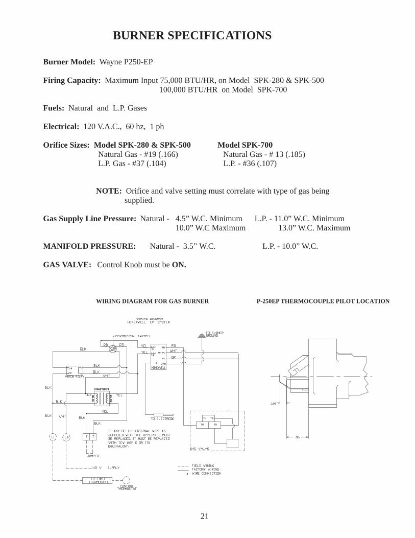
BURNER SPECIFICATIONS
Burner Model: Wayne P250-EP
Firing Capacity: Maximum Input 75,000 BTU/HR, on Model SPK-280 & SPK-500 100,000 BTU/HR on Model SPK-700
Fuels: Natural and L.P. Gases
Electrical: 120 V.A.C., 60 hz, 1 ph
Orifice Sizes: Model SPK-280 & SPK-500 Model SPK-700Natural Gas - #19 (.166) Natural Gas - # 13 (.185)
L.P. Gas - #37 (.104) L.P. - #36 (.107)
NOTE: Orifice and valve setting must correlate with type of gas being supplied.
Gas Supply Line Pressure: Natural - 4.5” W.C. Minimum L.P. - 11.0” W.C. Minimum 10.0” W.C Maximum 13.0” W.C. Maximum
MANIFOLD PRESSURE: Natural - 3.5” W.C. L.P. - 10.0” W.C.
GAS VALVE: Control Knob must be ON.
WIRING DIAGRAM FOR GAS BURNER P-250EP THERMOCOUPLE PILOT LOCATION
21
GAS PIPING INSTRUCTIONS
1. READ ALL GAS PIPING INSTRUCTIONS CAREFULLY BEFORE MAKING GAS CONNECTIONS.
WARNING: IMPROPER GAS HOOKUP WILL VOID WARRANTY AND COULD RESULT IN HAZARDOUS CONDITION.2. Connect the gas line to the 1/2 inch piping that extends from the Gas Burner. A 1/2 inch N.P.T. fitting is required.
NOTE: all piping must comply with local codes and ordinances of the National Gas Code ANSI Z 223.` - 1974 and NFPA #54.3. The gas line should be a separate supply direct from the meter to the Burner. It is recommended that a new pipe be used and located so that a minimum amount of work will be required in future servicing. The piping should be so installed as to be durable, substantial, and gas tight. It should be free from cutting burrs and defects in structure and threading.Cast iron fittings or aluminum tubing should not be used for the main gas circuit. Joint compounds (pipe dope) should be used sparingly on male threads only and be approved for all gases.
NOTE: The building structure should not be weakened by installation of the gas piping. The piping should not be supported by other piping, but should be firmly supported by pipe hooks, straps, bands, or hangers. Butt or lap welded pipe, pipe should not be bent.
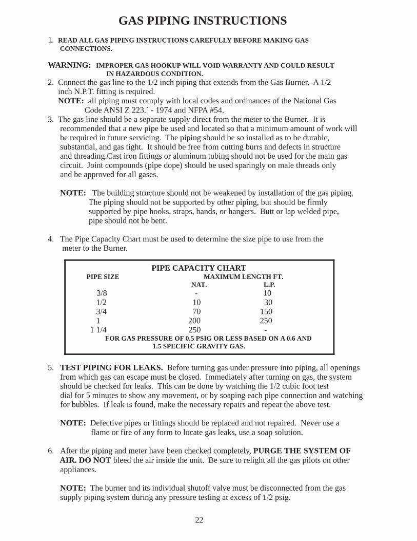
4. The Pipe Capacity Chart must be used to determine the size pipe to use from the meter to the Burner.
5. TEST PIPING FOR LEAKS. Before turning gas under pressure into piping, all openings from which gas can escape must be closed. Immediately after turning on gas, the system should be checked for leaks. This can be done by watching the 1/2 cubic foot test dial for 5 minutes to show any movement, or by soaping each pipe connection and watching for bubbles. If leak is found, make the necessary repairs and repeat the above test.
NOTE: Defective pipes or fittings should be replaced and not repaired. Never use a flame or fire of any form to locate gas leaks, use a soap solution.
6. After the piping and meter have been checked completely, PURGE THE SYSTEM OF AIR. DO NOT bleed the air inside the unit. Be sure to relight all the gas pilots on other appliances.
NOTE: The burner and its individual shutoff valve must be disconnected from the gas supply piping system during any pressure testing at excess of 1/2 psig.
22
PIPE CAPACITY CHART PIPE SIZE MAXIMUM LENGTH FT. NAT. L.P.
3/8 - 10 1/2 10 30 3/4 70 150 1 200 250 1 1/4 250 -
FOR GAS PRESSURE OF 0.5 PSIG OR LESS BASED ON A 0.6 AND1.5 SPECIFIC GRAVITY GAS.
23
1. It is recommended that the model SPK-Series ovens be vented as shown on page 23 or 24.
2. It is recommended that Local Code Officials and a Commercial Kitchen Ventilation Contractor be consulted prior to installation.
3. Provisions must be made for adequate air supply for the oven. If the oven is to be installed in a sealed room or building utilizing exhaust fans, the room must be supplied with a return air system. Return air must be equal or slightly higher than that of the exhausted air.
4. Unit must be level for proper grease drainage.
5. Minimum spacing to combustible materials: Back Side - 2” (10” recommended for service) Top - 18”; Left Side — 18” (Access for service) Note: If provision is made for service access, Left Side clearance can be reduced to 2”. Right Side — 24” (Access to load and unload firebox.); Front — 48” (access for loading and unloading product); Chimney Connectors-18” Floor — May be combustible material.
NOTE: On ovens that have the reverse firebox or mirror image option, (Facing the meat loading doors the firebox door is on the right) The minimum clearance dimensions for the left side and right side will be reversed.
NOTE: For flush mount, use BBR Insulation Kit #2099.
VENTING INSTRUCTIONS
VENTING INSTALLATIONS
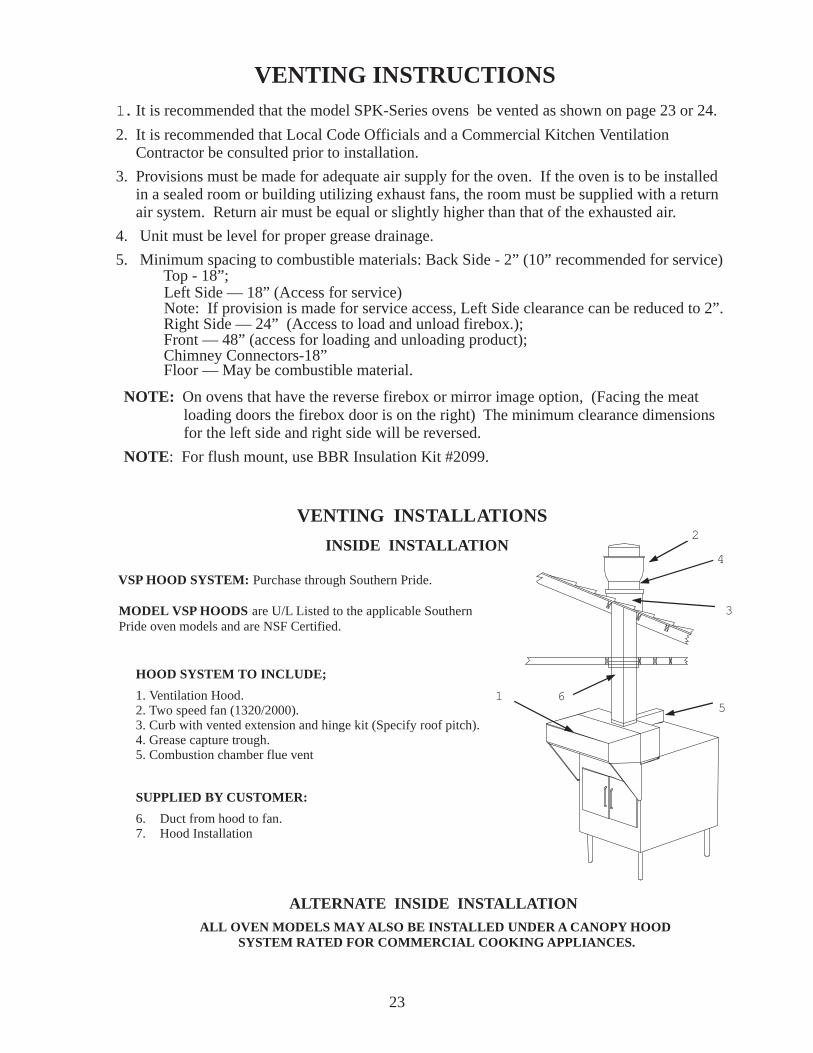
SUPPLIED BY CUSTOMER:
6. Duct from hood to fan.7. Hood Installation
HOOD SYSTEM TO INCLUDE;
1. Ventilation Hood.2. Two speed fan (1320/2000).3. Curb with vented extension and hinge kit (Specify roof pitch).4. Grease capture trough.5. Combustion chamber flue vent
6
4
2
1
3
INSIDE INSTALLATION
5
MODEL VSP HOODS are U/L Listed to the applicable SouthernPride oven models and are NSF Certified.
ALL OVEN MODELS MAY ALSO BE INSTALLED UNDER A CANOPY HOODSYSTEM RATED FOR COMMERCIAL COOKING APPLIANCES.
VSP HOOD SYSTEM: Purchase through Southern Pride.
ALTERNATE INSIDE INSTALLATION
10”ALL FUEL SM OKEEXTRACTOR CHIM NEY
RAINCAP
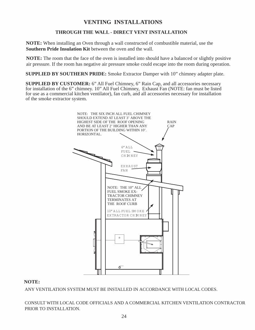
NOTE: THE SIX INCH ALL FUEL CHIMNEYSHOULD EXTEND AT LEAST 3’ ABOVE THEHIGHEST SIDE OF THE ROOF OPENINGAND BE AT LEAST 2’ HIGHER THAN ANYPORTION OF THE BUILDING WITHIN 10’.HORIZONTAL.
6”ALLFUELCHIM NEY
EXHAUSTFAN
NOTE: THE 10” ALLFUEL SMOKE EX-TRACTOR CHIMNEYTERMINATES ATTHE ROOF CURB
24
NOTE:
:
ANY VENTILATION SYSTEM MUST BE INSTALLED IN ACCORDANCE WITH LOCAL CODES.
CONSULT WITH LOCAL CODE OFFICIALS AND A COMMERCIAL KITCHEN VENTILATION CONTRACTORPRIOR TO INSTALLATION.
NOTE: When installing an Oven through a wall constructed of combustible material, use theSouthern Pride Insulation Kit between the oven and the wall.
THROUGH THE WALL - DIRECT VENT INSTALLATION
NOTE: The room that the face of the oven is installed into should have a balanced or slightly positiveair pressure. If the room has negative air pressure smoke could escape into the room during operation.
VENTING INSTALLATIONS
SUPPLIED BY SOUTHERN PRIDE: Smoke Extractor Damper with 10” chimney adapter plate.
SUPPLIED BY CUSTOMER: 6” All Fuel Chimney, 6” Rain Cap, and all accessories necessaryfor installation of the 6” chimney. 10” All Fuel Chimney, Exhaust Fan (NOTE: fan must be listedfor use as a commercial kitchen ventilator), fan curb, and all accessories necessary for installationof the smoke extractor system.
25
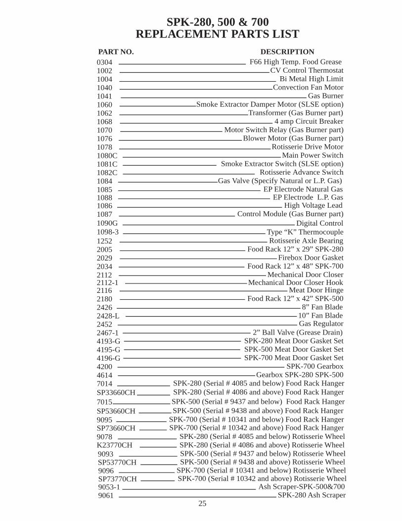
SPK-280, 500 & 700REPLACEMENT PARTS LIST
030410021004104010411060106210681070107610781080C1081C1082C10841085
PART NO. DESCRIPTIONF66 High Temp. Food Grease
CV Control ThermostatBi Metal High Limit
Convection Fan MotorGas Burner
Smoke Extractor Damper Motor (SLSE option)Transformer (Gas Burner part)
4 amp Circuit BreakerMotor Switch Relay (Gas Burner part)
Blower Motor (Gas Burner part)Rotisserie Drive Motor
Main Power SwitchSmoke Extractor Switch (SLSE option)
Rotisserie Advance SwitchGas Valve (Specify Natural or L.P. Gas)
EP Electrode Natural Gas
9061 SPK-280 Ash Scraper
10861087
High Voltage LeadControl Module (Gas Burner part)
125220052029203421122112-12116218024262428-L24522467-14193-G4195-G4196-G420046147014
Rotisserie Axle BearingFood Rack 12” x 29” SPK-280
Firebox Door GasketFood Rack 12” x 48” SPK-700
Mechanical Door Closer
Meat Door HingeFood Rack 12” x 42” SPK-500
8” Fan Blade10” Fan BladeGas Regulator
2” Ball Valve (Grease Drain)SPK-280 Meat Door Gasket SetSPK-500 Meat Door Gasket SetSPK-700 Meat Door Gasket Set
SPK-700 GearboxGearbox SPK-280 SPK-500
SPK-280 (Serial # 4085 and below) Food Rack Hanger
7015 SPK-500 (Serial # 9437 and below) Food Rack Hanger
9095 SPK-700 (Serial # 10341 and below) Food Rack Hanger
9078 SPK-280 (Serial # 4085 and below) Rotisserie Wheel
9093 SPK-500 (Serial # 9437 and below) Rotisserie Wheel
9053-1 Ash Scraper-SPK-500&700
9096 SPK-700 (Serial # 10341 and below) Rotisserie Wheel
1090G Digital Control1098-3 Type “K” Thermocouple
SP33660CH SPK-280 (Serial # 4086 and above) Food Rack Hanger
SP53660CH SPK-500 (Serial # 9438 and above) Food Rack Hanger
SP73660CH SPK-700 (Serial # 10342 and above) Food Rack Hanger
Mechanical Door Closer Hook
K23770CH SPK-280 (Serial # 4086 and above) Rotisserie Wheel
SP53770CH SPK-500 (Serial # 9438 and above) Rotisserie Wheel
SP73770CH SPK-700 (Serial # 10342 and above) Rotisserie Wheel
1088 EP Electrode L.P. Gas

ONE YEAR LIMITED WARRANTY(CONSULT FACTORY FOR DETAILS)
90 DAY LABOR WARRANTY (PRE AUTHORIZED)
Southern Pride guarantees all new equipment of its manufacture to be free of defects in material and factory workmanshipfor a period of one year provided that the equipment is installed in the Continental United States, Alaska, or Hawaii andoperated according to the Owner’s Manual while located at the original address of installation, the warranty registration cardhas been completed and returned to the factory within fifteen (15) days after installation and a start-up has been preformedby an authorized service agent.
Southern Pride’s obligation under this warranty is limited to one of the following options with the option applicable to beselected by Southern Pride at the sole discretion of Southern Pride.
1. Owner to return part, freight PREPAID, Southern Pride to repair at own expense if defective, and ship part back to owner freight collect.
2. Southern Pride to furnish replacement part, freight collect, without requesting return of the defective part.
3. Southern Pride to furnish replacement part, freight collect, in exchange for return of the defective part, freight collect.
Under certain circumstances Southern Pride will reimburse owner for limited labor costs in replacing parts during a periodof not more than ninety (90) days after installation, (provided that work is prior authorized and confirmed by SouthernPride’s Service Manager.)
Because Southern Pride does not and cannot control the owner’s installation, use and maintenance of equipment manufacturedby Southern Pride this warranty does not cover: any equipment installed improperly; any equipment calibrated afterstart-upand acceptance; any component disassembled in the field; damaged due to improper cleaning, i.e. burner (hosing or “wateringdown” machines will cause electrical failures not covered by warranty); blown fuses, light bulbs, gaskets,electric elements andaccessory components not installed or manufactured by Southern Pride. Shipping damage mustbe reported to the carrier andis not covered under this warranty.
Southern Pride will not be liable for damage as a result of improper installation, misuse, abuse, alteration of original design,incorrect voltage, unauthorized service, or breakage of fragile items, Southern Pride will not be liable for any loss or conse-quential damage or expense accruing directly or indirectly from the use of equipment covered by this warranty including anyproduction or product losses or other damages which may occur as a result of equipment malfunction or failure. This warrantydoes not cover cooking performance, which is a function of food types, textures, temperatures and other variables chosen bythe owner and over which Southern Pride has no control. The effect of corrosion, fire and normal wear on the equipment orcomponent parts is not covered by this warranty. This warranty does not apply to damage caused by accident or to damagecaused by the negligence of the owner and the employees of the owner or to damaged caused by lightning generatedelectrical current or any other Act of God whatsoever. This warranty does not apply to any equipment bearing a serialnumber which has been tampered with or altered.
This warranty is exclusive and is in lieu of all other warranties, express or implied, including any implied warranty ormerchantability or fitness for particular purpose, each of which is hereby expressly disclaimed, the remedies described aboveare exclusive and in no event shall Southern Pride be liable for special, consequential or incidental damages for the breach ordelay in performance of warranty.
TERMS AND CONDITIONS
For purposes of definition and interpretation, the term “Seller” as used herein refers to Southern Pride and the term “Buyer”refers to the originator of a specific purchase order to Southern Pride.
Possession of a price list does not necessarily constitute an offer to sell by Southern Pride. Prices and specifications are sub-ject to change without notice. All items will be invoiced at prices in effect at time of shipment. Equipment prices do not in-clude federal, state, city or local taxes which may apply and all sales are subject thereto. No order, whether written or oral ,shall result in a contact, unless it is accepted and acknowledged in writing by Seller at Seller’s office in Marion, Illinois.
Shipping weights are approximate and all prices are quoted F.O.B. Marion, Illinois. All “common carrier” shipped equipmentshall be domestic crated; all others shall be uncrated and subject to delivery charge per zone chart. Any equipment held forshipment upon Buyer’s request beyond the delivery date specified on original purchase order will be due and payable withinterms and will result in storage charges.
Delivery estimates are figured from date written orders are received and accepted by Seller. Seller will meet Buyer’s deliveryrequest as nearly as possible but does not guarantee shipment nor delivery on any particular date. Seller reserves right to shipmerchandise via any responsible carrier. Seller’s responsibility ceases upon acceptance by carrier. Buyer is expected to ex-amine contents of shipments and immediately report any damage to carrier authorities.
Payment terms shall be 30% deposit with order; balance prior to delivery unless otherwise agreed in writing by Seller. Returnsof any merchandise may not be made without Seller’s written approval, prior to return. Seller shall impose a 20% restockingcharge for handling of any returns. All cancellations must be in writing. Cancellations are also subject to a 20% fee.
26Revised 2/9/08
Top Related