

![arXiv:1812.10191v2 [cs.CV] 22 Mar 2019 · 2019-03-25 · FPD-M-net. The details of network architecture, training and loss function are described next. 2.1 FPD-M-net architecture](https://static.fdocuments.net/doc/165x107/5ece022d84f3a7545805d0fc/arxiv181210191v2-cscv-22-mar-2019-2019-03-25-fpd-m-net-the-details-of-network.jpg)


Languages
Pages
Legal


1
New Features of
MELSERVO-J4 Function Guide

2
A complete system lineup to meet your production and manufacturing needs
MELSEC iQ-R series
RJ71GF11-T2QJ71GF11-T2
RD77GFQD77GF
RD77MSQD77MS
LD77MS Q170MSCPUQ17nDSCPURnMTCPUFX5-40SSC-SFX5-80SSC-S
Q173SCCF
MR-J4-GF(-RJ) MR-J4W2-0303B6 MR-J4-A(-RJ) MR-J4-03A6(-RJ)MR-J4-B(-RJ/-LL)MR-CV+MR-J4-DU_B(-RJ) MR-J4W2-B MR-J4W3-B
MELSEC-Q series MELSEC-QS/WS series
Medium/large capacity, low inertia
Ultra-large capacity*2
Core type
Coming in futureCore type with magnetic attraction counter-force Coreless type
Core type (natural/liquid cooling)Small capacity, ultra-low inertia
Medium capacity, ultra-low inertia
Medium capacity, flat type
Small capacity, low inertia
CC-Link IE Field Network compatible servo amplifier
CC-Link IE Field Network SSCNET III/H SSCNET III/H SSCNET III/H
e-F@ctory is the Mitsubishi Electric solution for improving the performance of any manufacturing enterprise by
enhancing productivity, and reducing the maintenance and operation costs together with seamless information
flow throughout the plant.
Mitsubishi Electric's integrated FA platform for achieving lateral integration of controllers &
HMI, engineering environments and networks at production sites.
SSCNET III/H compatible servo amplifier
Power regeneration converter unit + SSCNET III/H compatible drive unit
SSCNET III/H compatible 2-axis servo amplifier
SSCNET III/H compatible 2-axis servo amplifier Ultra-small capacity
General-purpose interface servo amplifier
*1. RS-485 is supported by MR-J4-A(-RJ). (but not by MR-J4-03A6(-RJ))
*2. MODBUS® RTU is supported by MR-J4-A-RJ. (but not by MR-J4-03A6-RJ)
General-purpose interface servo amplifier Ultra-small capacity
SSCNET III/H compatible 3-axis servo amplifier
Ultra-compact size,ultra-small capacity
Medium capacity, medium inertia
Capacity: 0.5 to 55 kW
Capacity: 110 to 220 kW
Rating: 70 to 960 N
Rating: 120 to 2400 N Rating: 50 to 800 N
Rating: 300 to 3000 N (natural cooling)Rating: 600 to 6000 N (liquid cooling)Capacity: 50 to 750 W
Capacity: 1 to 5 kW Capacity: 0.75 to 5 kW
Capacity: 50 to 750 W
Capacity: 10 to 30 W
*1. Refer to "MELSERVO-J4 catalog (L(NA)03058)" for the combination. *2. Contact your local sales office for details.
Capacity: 0.5 to 7 kW
HG-JR series
HG-JR series
LM-H3 series
LM-K2 series LM-U2 series
LM-F seriesHG-MR series
HG-RR series HG-UR series
HG-KR series
HG-AK series
HG-SR series
MELSEC-L series MELSEC iQ-F series MELSEC-F series GOT2000
CONTROLLER
SERVOAMPLIFIER
INTERFACE
SOLUTION PLATFORM
SERVOMOTOR*1
Rotary servo motor
Programmable controller Graphic operation terminal
Simple Motion moduleMaster/local module C controller interface module Motion controller
CC-Link IE Field Network SSCNET III/H Pulse train/analog voltage/RS-422/RS-485*1/MODBUS®RTU*2
Linear servo motor

3
Failure Prediction ................................................... 4
Drive Recorder ........................................................ 5
Master-Slave Operation ......................................... 6
Super Trace Control ................................................ 7
Simple Cam .............................................................. 8
Functional Safety .................................................. 10
Monitoring ............................................................ 11
One-Touch Tuning ................................................. 12
Multi-Axis Adjustment ......................................... 13
Pressure Control .................................................. 14
GF MR-J4-GF GF-RJ MR-J4-GF-RJ B MR-J4-B/MR-J4-DU_B B-RJ MR-J4-B-RJ/MR-J4-DU_B-RJ
B-LL MR-J4-B-LL WB MR-J4W2-B/MR-J4W3-B/MR-J4W2-0303B6 A MR-J4-A/MR-J4-DU_A/MR-J4-03A6
A-RJ MR-J4-A-RJ/MR-J4-DU_A-RJ/MR-J4-03A6-RJ
Functions
MELSERVO-J4 and our servo products come with a wide selection of functions to solve the challenges in production. Our newest functions are easier to use, and safer than ever before.
Man, machine and environment
in perfect harmony
To respond to an expanding range of applications including semiconductor and FPD manufacturing, robots, and food processing machines, MELSERVO-J4 combines with other Mitsubishi Electric product lines such as Motion controllers, networks, graphic operation terminals, programmable controllers and more. This gives you the freedom and flexibility to create a more advanced servo system.
MR-MC2_ _MR-EM340GF RD75PRD75D
QD75PQD75D
LD75PLD75D
FX2N-10PG
WS-V MS-TMR-MT2000 series
Low-profile table typeNEW NEWLow-profile flange type
SSCNET III/H SSCNET III/HCC-Link IE Field Network
*1. RS-485 is supported by MR-J4-A(-RJ). (but not by MR-J4-03A6(-RJ))
*2. MODBUS® RTU is supported by MR-J4-A-RJ. (but not by MR-J4-03A6-RJ)
General-purpose interface servo amplifier Ultra-small capacity
SSCNET III/H compatible sensing module
Rating: 2.2 to 9 N·m
Rating: 2 to 240 N·m
Rating: 2.2 to 9 N·m
TM-RU2M series
TM-RFM series
TM-RG2M series
SOFTWARE
SENSING MODULE
LOW-VOLTAGESWITCHGEAR
Graphic operation terminal Personal computer MELSOFT GX Works3
MELSOFT MT Works2
MELSOFT MR Configurator2
Capacity selection software
Motion controller Position board Positioning moduleSimple Motion board
SSCNET III/HPulse train/analog voltage/RS-422/RS-485*1/MODBUS®RTU*2
Linear servo motor Direct drive motor
Molded-case circuit breaker Magnetic contactor
Related catalogs
MELSERVO-J4 CatalogL(NA)03058
GOT2000 SeriesDrive Control Interactive SolutionsL(NA)08335ENG

Solder paste inspection (SPI) machine
Screen printer
Unloader Automatic optical inspection (AOI) machine
Reflow oven
Loader
Surface mounting line
Example: alarm display
[ Interactive functions ]Drive recorder function/Machine diagnosis function/Servo amplifier life diagnosis function/One-touch tuning
The GOT2000 provides some functions of MR Configurator2. The new GOT Drive enhanced functionality is designed to eliminate need for additional hardware, software and suits customers’ applications to speed up system startup, improve maintenance and troubleshooting.
Serial, Ethernet, etc.
Motion controller/Simple Motion moduleGOT2000 Servo amplifier
GOT and Servo System Configurations
Chip mounter
4
Predictive maintenance is a key to avoid unplanned production downtime. With the failure prediction functions, failures can be easily predicted in advance. By utilizing failure prediction data to schedule maintenance at optimal times, unplanned downtime is avoided, improving operation rates for the entire production line.
Friction failure prediction functionPredicts failure based on changes in the coulomb and viscous friction of guides and ball screws.
Vibration failure prediction functionPredicts failure based on aging in guides, ball screws, and belts from the vibration and frequency changes.
Total distance failure prediction functionPredicts failure based on the total travel distance of the servo motor to determine when ball screws and bearings are approaching product life.
* The failure prediction function is available with MR-J4-GF(-RJ) servo amplifiers with software version A3 or later.
* Note that this function does not guarantee the prediction of all failures.
Failure prediction for improved operation rates
Failure Prediction
Optimal solution with MELSERVO-J4
1 Predictive maintenance of mechanical drive components
2 Improvement of operation rate
Supported by: GF GF-RJ
Recommended applications
Automotive production lines/Semiconductor manufacturing lines/FPD manufacturing lines/Surface mounting lines, etc.
Normal
Failure
Dynamic friction/vibration level
MR-J4-GF(-RJ)
Machine failure
Component life
Failure warning limit
Time
Time
Servomotor
Servomotor
Servo motor total travel distance
Failure warning limit
Sign of failure
Informingmaintenance
timing
Failurewarning
Failurewarning
Solder paste inspection (SPI) machine
Screen printer
Unloader Automatic optical inspection (AOI) machine
Reflow oven
Loader
Surface mounting line
Example: alarm display
[ Interactive functions ]Drive recorder function/Machine diagnosis function/Servo amplifier life diagnosis function/One-touch tuning
The GOT2000 provides some functions of MR Configurator2. The new GOT Drive enhanced functionality is designed to eliminate need for additional hardware, software and suits customers’ applications to speed up system startup, improve maintenance and troubleshooting.
Serial, Ethernet, etc.
Motion controller/Simple Motion moduleGOT2000 Servo amplifier
GOT and Servo System Configurations
Chip mounter
5
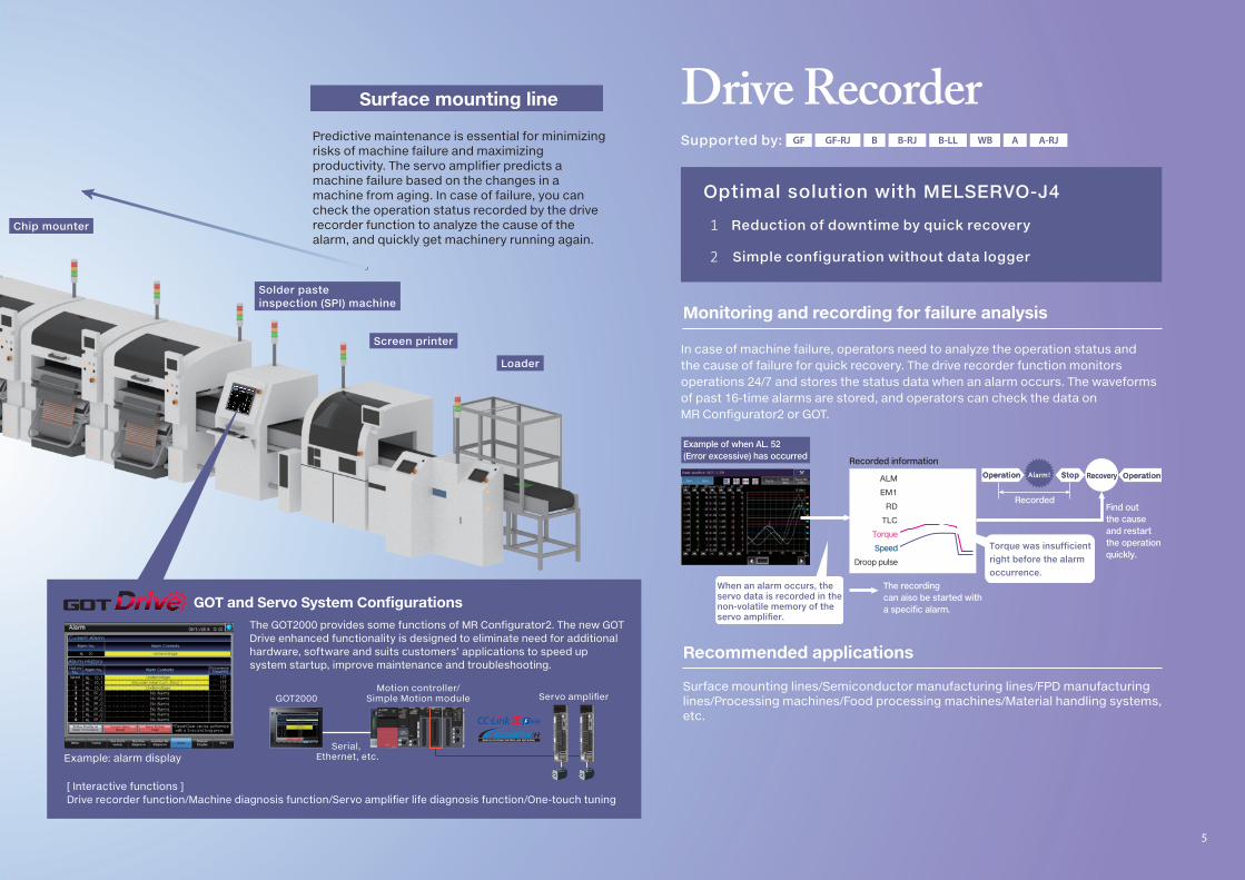
In case of machine failure, operators need to analyze the operation status and the cause of failure for quick recovery. The drive recorder function monitors operations 24/7 and stores the status data when an alarm occurs. The waveforms of past 16-time alarms are stored, and operators can check the data on MR Configurator2 or GOT.
Drive Recorder
Optimal solution with MELSERVO-J4
1 Reduction of downtime by quick recovery
2 Simple configuration without data logger
Supported by: GF GF-RJ B B-RJ B-LL WB A A-RJ
OperationOperation
Example of when AL. 52 (Error excessive) has occurred
Recorded
Recorded information
ALM
EM1
RD
TLC
Torque
SpeedSpeed
Droop pulse
OperationOperation
Find out the cause and restart the operationquickly.
StopStop RecoveryRecoveryAlarm!
The recording can aiso be started with a specific alarm.
When an alarm occurs, the servo data is recorded in the non-volatile memory of the servo amplifier.
When an alarm occurs, the servo data is recorded in the non-volatile memory of the servo amplifier.
Torque was insufficient right before the alarm occurrence.
Torque was insufficient right before the alarm occurrence.
Predictive maintenance is essential for minimizing risks of machine failure and maximizing productivity. The servo amplifier predicts a machine failure based on the changes in a machine from aging. In case of failure, you can check the operation status recorded by the drive recorder function to analyze the cause of the alarm, and quickly get machinery running again.
Recommended applications
Monitoring and recording for failure analysis
Surface mounting lines/Semiconductor manufacturing lines/FPD manufacturing lines/Processing machines/Food processing machines/Material handling systems, etc.

ActualpathActualpath
Commanded pathCommanded path
Without super trace control With super trace control
Master axisSlave axis
Slave axisSlave axis
Deviation is reduced with super trace control.
ActualpathActualpath
Commanded pathCommanded path
Guided vehicle
Simplified machine tools
6
Master-Slave Operation
While the master axis is operated in position or speed control mode, the slave axes are operated in torque control mode with the same torque as the master axis. Since multiple smaller-capacity servo motors are used for sharing load instead of a large-capacity servo motor, minimal space can be effectively used. The torque command is transmitted from the master axis to the slave axes via SSCNET III/H with a parameter setting, and no additional wiring is required for this function.Each SSCNET III/H line can have up to eight master axes.
Torque-coordination of multiple axes
Optimal solution with MELSERVO-J4
1 Easy configuration of torque-assist system
2 Space utilization with distributed arrangement of slave axes
SSCNET III/H compatible Motion controller
Master axisPosition/speed control
MR-J4-B(-RJ) MR-J4-B(-RJ)
Slave axisTorque control
Position/speed command Torque command
Drives with the same torque as the master axis
The stable operation and simple configuration of a guided vehicle is possible when multiple servo motors in a distributed arrangement all operate with the same torque as the master axis.
Recommended applications
Press machines/Molding machines/Material handling systems, etc.
Supported by: B B-RJ
ActualpathActualpath
Commanded pathCommanded path
Without super trace control With super trace control
Master axisSlave axis
Slave axisSlave axis
Deviation is reduced with super trace control.
ActualpathActualpath
Commanded pathCommanded path
Guided vehicle
Simplified machine tools
7
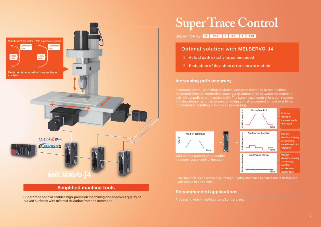
Position deviation increases with the speed.
Positiondeviation is nearly zero during a constant-velocity operation.
Positiondeviation is nearly zero during a constant acceleration/deceleration.
Position command
Speed
Time
Normal control
Posi
tion
devi
atio
n
Time
Feed forward control
Posi
tion
devi
atio
n
Time
Super trace control
Posi
tion
devi
atio
n
Time
In normal control, a position deviation occurs in response to the position command from the controller, causing a deviation error between the machine axis' target path and the actual path. The super trace control function reduces this deviation error close to zero, enabling actual movement almost exactly as commanded, resulting in improved processing.
* This function is applicable only for high-rigidity machines because the feed forward gain needs to be set high.
Just set the parameter to enable the super trace control function.
Increasing path accuracy
Super Trace Control
Optimal solution with MELSERVO-J4
1 Actual path exactly as commanded
2 Reduction of deviation errors on arc motion
Supported by: GF GF-RJ B B-RJ A A-RJ
Super trace control enables high-precision machining and improves quality of curved surfaces with minimal deviation from the command.
Recommended applications
Processing machines/Mounters/Bonders, etc.

A/B-phase pulse
A/B-phase pulse
Synchronous encoder
Mark sensor
The mark sensor input compensation function corrects the position of the knife axis.
The synchronous encoder signals are inputted with the encoder following function.
With the command pulse input through function, the knife axis and processing axis are synchronized.
Conveyor axis
Knife axis
Processing axis
Rotary Knife
8
A wider variety of applications with the additional new functions
Simple cam setting window of MR Configurator2
Simple cam functionSmooth conveyance and stoppage by cam control based on the cam data
New functions for positioning
Create various cam data patterns with MR Configurator2.
Feeding motion
t
Any point can be set as an end point of the feeding motion.
Belt conveyor Rotary table
Cam motion which resets a camreference position per cycleLinear cam motion by one cycle
Linear motion
Ball screw Rotary table
t
Reciprocating motion
t
Reciprocating cam
Reciprocating cam motion within a cam stroke range
Simple Cam
Optimal solution with MELSERVO-J4
1 Cam control with multiple synchronized axes
2 Compensation of position errors
3 Cost-effective configuration without a Positioning module
Supported by: A-RJ
Save time by having cam data automatically generated to suit the sheet length, radius of the rotary knife, and synchronous section of the sheet. The mark sensor input compensation function ensures that the cutting position is accurate by correcting position deviations that occur from the sheet stretching/contracting.

A/B-phase pulse
A/B-phase pulse
Synchronous encoder
Mark sensor
The mark sensor input compensation function corrects the position of the knife axis.
The synchronous encoder signals are inputted with the encoder following function.
With the command pulse input through function, the knife axis and processing axis are synchronized.
Conveyor axis
Knife axis
Processing axis
Rotary Knife
9
Û RJ-45 junction connector terminal block and RJ-45 compatible cable designed for MR-J4-A-RJ are required.
Communication function (MODBUS® RTU)MR-J4-A-RJ supports not only RS-422/RS-485 communication (Mitsubishi Electric AC Servo Protocol) but also RS-485 communication (MODBUS® RTU protocol). MODBUS® RTU protocol is compatible with function code 03h (Read holding registers), etc. The cam data can be set through MODBUS® RTU.
Additional function
Encoder following functionThis function allows the synchronous encoder signals to be used as command pulses.
Command pulse input through function The first servo amplifier axis outputs command pulses to the subsequent axes, enabling a synchronous system of multiple axes.
Mark sensor input compensation functionThe servo amplifier compensates a position error between the reference position and the position detected by a sensor, allowing the workpiece to be cut correctly on a registration mark.
MODBUS® RTU
MR-J4-A-RJ
HMI Temperature control module
Measuring device
Master device such as programmable controller
Slave device
Inverter
Recommended applications
Rotary knife devices/Simple packaging machines/Sheet pasting machines, etc.
+
Less wiring without an external encoder on the machine×
HUB*2
HMI
Safety signal
Safety switch
Safety signal
Safety signal
Complies with Category 3 and Category 4
enables...
Safety controller
MR-J4-B-RJ
MR-D30
Light curtain
Remote I/O
Inverter
Control room
Servo motor with functional safety
!
Automobile production line
10
For the maximum level of safety required by FA systems
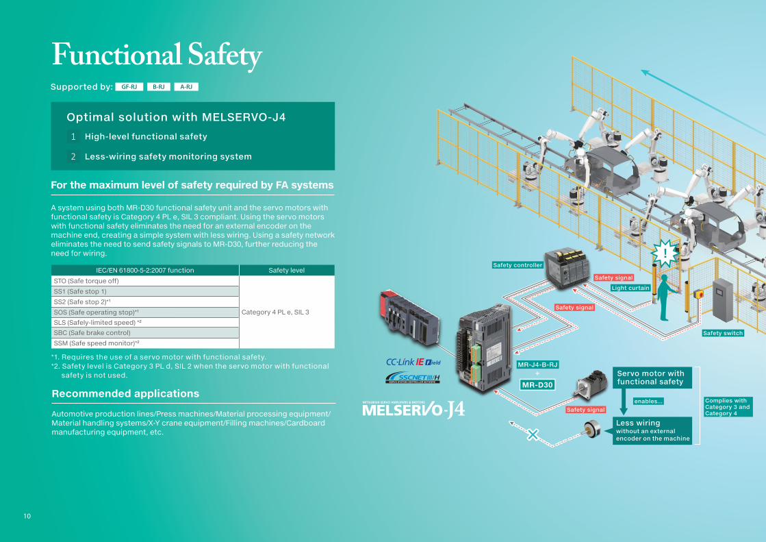
IEC/EN 61800-5-2:2007 function Safety level
STO (Safe torque off)
Category 4 PL e, SIL 3
SS1 (Safe stop 1)
SS2 (Safe stop 2)*1
SOS (Safe operating stop)*1
SLS (Safely-limited speed) *2
SBC (Safe brake control)
SSM (Safe speed monitor)*2
*1. Requires the use of a servo motor with functional safety.*2. Safety level is Category 3 PL d, SIL 2 when the servo motor with functional
safety is not used.
Functional Safety
A system using both MR-D30 functional safety unit and the servo motors with functional safety is Category 4 PL e, SIL 3 compliant. Using the servo motors with functional safety eliminates the need for an external encoder on the machine end, creating a simple system with less wiring. Using a safety network eliminates the need to send safety signals to MR-D30, further reducing the need for wiring.
Optimal solution with MELSERVO-J4
1 High-level functional safety
2 Less-wiring safety monitoring system
Supported by: GF-RJ B-RJ A-RJ
Recommended applications
Automotive production lines/Press machines/Material processing equipment/Material handling systems/X-Y crane equipment/Filling machines/Cardboard manufacturing equipment, etc.

+
Less wiring without an external encoder on the machine×
HUB*2
HMI
Safety signal
Safety switch
Safety signal
Safety signal
Complies with Category 3 and Category 4
enables...
Safety controller
MR-J4-B-RJ
MR-D30
Light curtain
Remote I/O
Inverter
Control room
Servo motor with functional safety
!
Automobile production line
11
Monitoring
*1. TCO: Total Cost of Ownership*2. When using motion mode, a dedicated hub for CC-Link IE Field Network is
necessary. Refer to "MELSERVO-J4 catalog (L(NA)03058)" for details.
Servo status monitor Power monitor Machine diagnosis
Effective load ratio/bus voltage/internal temperature of encoder
Unit power consumption/total power consumption
Estimated friction and vibration values
Integrated information management is necessary for manufacturers to seek solutions for reducing cost and improving systems. The servo amplifier offers constant monitoring of power consumption and operation status of the servo amplifiers and servo motors, and the data is transmitted from the servo amplifier to a controller via CC-Link IE Field Network or SSCNET III/H for more cost-effective information management, helping optimize the production site.
TCO*1 reduction with effective use of servo information
Optimal solution with MELSERVO-J4
1 Reduction of machine downtime caused by failure
2 Monitoring power consumption for energy saving
3 Integrated management of line operation information
Supported by: GF GF-RJ B B-RJ B-LL WB
A Category 4 PL e compliant safety system can be constructed with simple wiring. By using the safety integrated MR-J4 and MR-D30, machinery turns off when the light curtain is obstructed, and the unintended restart of machinery is prevented. The monitoring function also allows the centralized control of servo and mechanical drive components, helping save energy and schedule maintenance, and enabling quick recovery from machinery failures.
Recommended applications
Semiconductor manufacturing lines/FPD manufacturing lines/Automobile production lines/Gear grinding machines/Bearing insertion machines, etc.

Adjustment time can be reduced by minimum of
50%!
One-touch tuning for
a wide variety of machines
Material handling systems
Filling machines
Coater
Screen printers
12
Gain adjustment has never been easier. With the one-touch tuning, machine resonance filters, advanced vibration suppression control II, and robust filters are automatically adjusted, enabling high-response yet stable operations and shorter settling time.
With the user command method, the one-touch tuning is enabled also with a command inputted from outside the servo amplifier.
All you need is to set the servo motor permissible travel distance in the amplifier command method, and appropriate commands for the one-touch tuning will be created to adjust the gains.
Easy gain adjustment
Shorter adjustment time with "amplifier command method" NEW
One-touch Tuning
Optimal solution with MELSERVO-J4
1 Gain adjustment in less time
2 Easy-to-use advanced vibration suppression control
Travel amount(shaded area)
Speed
Time
Adjusted with actual operation command
Time
Speed
*1. The amplifier command method will be supported by MR-J4-GF(-RJ) in the future.*2. MR-J4-B-LL does not support the amplifier command method. One-touch tuning is not
available when the MR-J4-B-LL is used in the pressure control mode.
[Amplifier command method]
[User command method]
Supported by: GF*1 GF-RJ*1 B B-RJ B-LL*2 WB A A-RJ
Recommended applications
Screen printers/Material handling systems/Filling machines/Mounters/Take-out Robots/Automatic assembly equipment/Motion alignment/Polishing systems, etc.

Adjustment time can be reduced by minimum of
50%!
One-touch tuning for
a wide variety of machines
Material handling systems
Filling machines
Coater
Screen printers
13
When multiple axes are used in equipment, adjusting gain is time-consuming work even for experienced personnel. Now, the gain adjustment time can be cut to half with the multi-axis adjustment function. This function simultaneously adjusts parallel drive axes which make the same motion and also executes test operation and gain adjustment for up to four axes at the same time. The target axes can be selected with a simple operation on the engineering software.
Test operation window Gain adjustment window
Quick startup by simultaneous gain adjustment
Multi-axis Adjustment
Optimal solution with MELSERVO-J4
1 Simultaneous gain adjustment for parallel drive axes
2 Simultaneous test operation on multiple axes
Û The multi-axis adjustment function is enabled when the servo amplifier and RnMTCPU or RD77MS are combined.
The multi-axis adjustment enables a test operation and gain adjustment on multiple axes simultaneously, making the startup time shorter. This function is useful for coaters having a coating head driven by two servo motors.
Supported by: B B-RJ WB
Recommended applications
Material handling systems/Automatic assembly equipment/Mounters/Servo press machines/Coaters, etc.
Pressure command
Pressure feedback
Pressure sensor amplifier
Pressure sensor
MR-J4-B-LL
Press machines
14
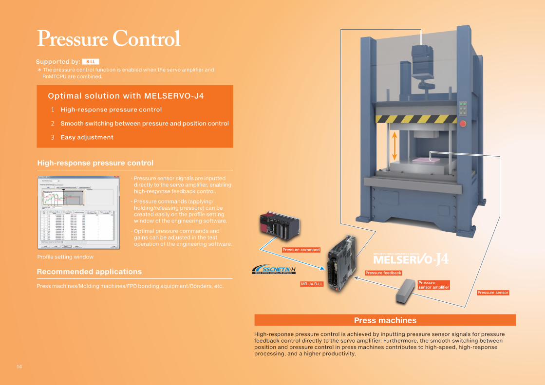
- Pressure sensor signals are inputted directly to the servo amplifier, enabling high-response feedback control.
- Pressure commands (applying/holding/releasing pressure) can be created easily on the profile setting window of the engineering software.
- Optimal pressure commands and gains can be adjusted in the test operation of the engineering software.
Pressure Control
Profile setting window
High-response pressure control
Optimal solution with MELSERVO-J4
1 High-response pressure control
2 Smooth switching between pressure and position control
3 Easy adjustment
Supported by: B-LL
High-response pressure control is achieved by inputting pressure sensor signals for pressure feedback control directly to the servo amplifier. Furthermore, the smooth switching between position and pressure control in press machines contributes to high-speed, high-response processing, and a higher productivity.
Recommended applications
Press machines/Molding machines/FPD bonding equipment/Bonders, etc.
Û The pressure control function is enabled when the servo amplifier and RnMTCPU are combined.

Pressure command
Pressure feedback
Pressuresensor amplifier
Pressure sensor
MR-J4-B-LL
Press machines
15

16
L(NA)03152ENG-A 1710(MEE) New publication, effective Octorber 2017.
Specifications are subject to change without notice.
HEAD OFFICE: TOKYO BLDG., 2-7-3, MARUNOUCHI, CHIYODA-KU, TOKYO 100-8310, JAPAN
•Ethernet is a registered trademark of Fuji Xerox Co., Ltd. in Japan.
•All other company names and product names used in this document are
trademarks or registered trademarks of their respective companies.
Registration
Safety WarningTo ensure proper use of the products listed in this catalog, please be sure to
read the instruction manual prior to use.
MELSERVO-J4 Function Guide
Top Related