


Languages
Pages
Legal

29 August 2012
1
August 2012
MEK4450
05 Templates and Manifolds
© Det Norske Veritas AS. All rights reserved.
August 2012
2
Templates & Manifolds
This module will cover:
Applicable Codes and Standards
Templates
- Purpose of a template
Manifolds
- Purpose of a manifold
Foundations

29 August 2012
2
© Det Norske Veritas AS. All rights reserved.
August 2012
3
Goal
Differentiate different methods and understand reason for choosing different design
© Det Norske Veritas AS. All rights reserved.
August 2012
4
Codes and standards
The following standards are a selection normally used for template/manifold design. The code requirements will vary with customer preference and local legislation
- ISO 13628-1- Steel structure: NS 3472 (Design methods and utilization of material, does not
cover loads)- NORSOK U-001 (Dropped object)- ASME B 31.3- ASME B 31.8- DNV-OS-F101- BS8010 Part 3- DNV Rules for planning and Execution of Marine Operation
- New Standard proposed: ISO 13628-15 “Structures and Manifolds”

29 August 2012
3
© Det Norske Veritas AS. All rights reserved.
August 2012
Purpose of template
Being the guide, hang off and support to drilling and the wellhead conductor.
Can be integrated with protection against fishing gear and dropped objects
Based on seabed condition will the template be designed with- Mudmats as foundation and provide bearing capacity to avoid settlements
- Skirt to penetrate seafloor for resist lateral forces
- Skirt to provide friction against heave during installation
- Washout sleeve to avoid shortfall and fracture in seabed during 36” drilling
- Suction system to assist in penetrating the seafloor and leveling
5
© Det Norske Veritas AS. All rights reserved.
August 2012
6
Templates
The function of the template will vary with:
Location- Local legislation
Installation methods- Moonpool, drillpipe, cranevessel, modular, barge or wet tow
Pipeline methods- Horizontal or vertical flowline connection, pipeline forces,
Protection requirements- Fishing gear protection, dropped objects
Drilling methods- Suction of drill cuttings, cement suction, drill cutting injection

29 August 2012
4
© Det Norske Veritas AS. All rights reserved.
August 2012
Foundations
Template Foundations with skirts or mini-suction piles :
Installed before main manifold so reduced weight
Allow drilling taking place (Normally one season prior to manifold installation)
Each skirt (or mini pile) can be sucked down individually to adjust elevation
Supports weight of manifold or template and anchors it in place on the seabed
7
Aker Solutions
© Det Norske Veritas AS. All rights reserved.
August 2012
8
Fixed Template – Production Guidebase
Aker Solutions

29 August 2012
5
© Det Norske Veritas AS. All rights reserved.
August 2012
9
Modular Manifold / Template
TRIPLEPORCH
MUDMAT
CENTREPILE
EWA
HOGS
DRILL CUTINJECTION
PGBPGB
MANIFOLD PIG LOOPMODULE
PIG LOOPPORCH
CENTRESECTION
MANIFOLD ROOFPROTECTION
© Det Norske Veritas AS. All rights reserved.
August 2012
Single Suction Piles
Key features :
Supports vertical and horizontal loads on the manifold
Also used as anchor foundations for FPSO or Semi-submersible moorings
Installed partially by self weight and then by ROV deployed pump
Can be recovered by reverse pumping
May be designed so that orientation is not critical during installation
10
29 August 2012
6
© Det Norske Veritas AS. All rights reserved.
August 2012
11
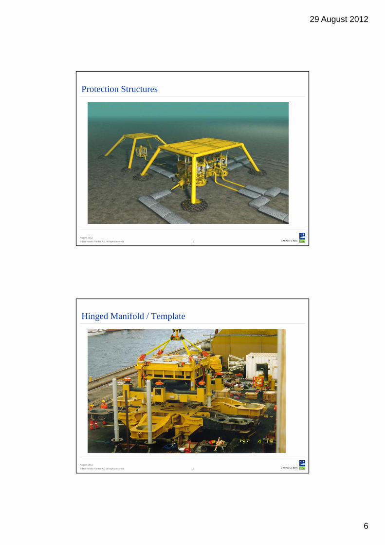
Protection Structures
© Det Norske Veritas AS. All rights reserved.
August 2012
12
Hinged Manifold / Template

29 August 2012
7
© Det Norske Veritas AS. All rights reserved.
August 2012
Manifold functions
ISO 13628-1:
“A manifold is a system of headers, branched piping and valves used to gather produced fluids or to distribute injected fluids. (ISO 13628-1). The manifold should provide sufficient piping, valves and flow controls to safely gather produced fluids or distribute injected fluids such as gas, water or chemicals”.
Purpose of Manifold
The purpose of the manifold is to ”commingle” the fluid flow and to proved isolation where required.
The Manifold Module provides the interface between the production pipeline, flowline and well.
Pipelines or flexibles normally interconnect the manifold.
Collecting produced fluids from individual subsea wells.
Distributing production fluids, inject gas, inject chemicals and control fluids.
Distribute the electrical and hydraulic system.
Several XT can be connected to the manifold.
Satellite modules (if required) will be connected to the manifold via a flow line.
14
© Det Norske Veritas AS. All rights reserved.
August 2012
15
Templates and Manifolds
In Norwegian terms the manifold is often referred to as the “Template/Manifold”, since the manifold is an integral part of the template.
Retrievable Manifold
Aker Kværner Subsea, Kristin project
29 August 2012
8
© Det Norske Veritas AS. All rights reserved.
August 2012
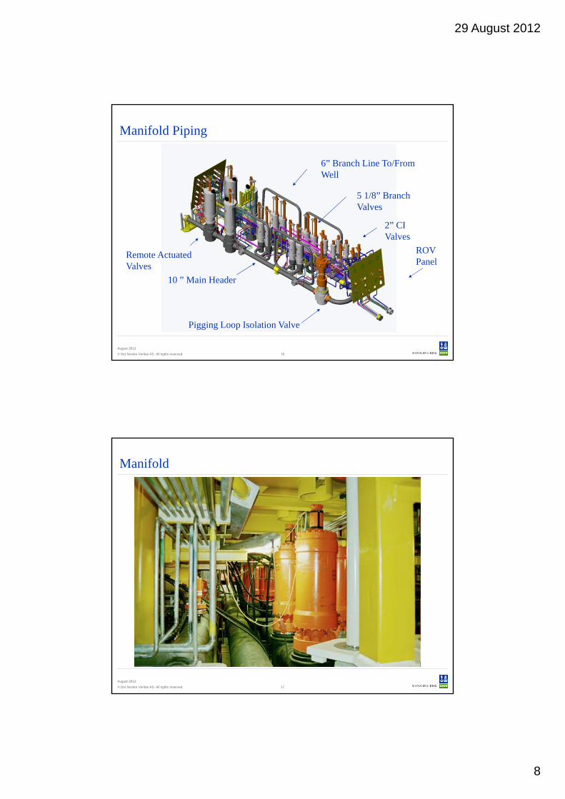
Manifold Piping
6” Branch Line To/From Well
Remote Actuated Valves
10 ” Main Header
5 1/8” Branch Valves
Pigging Loop Isolation Valve
2” CI Valves
ROV Panel
16
© Det Norske Veritas AS. All rights reserved.
August 2012
17
Manifold
29 August 2012
9
© Det Norske Veritas AS. All rights reserved.
August 2012
18
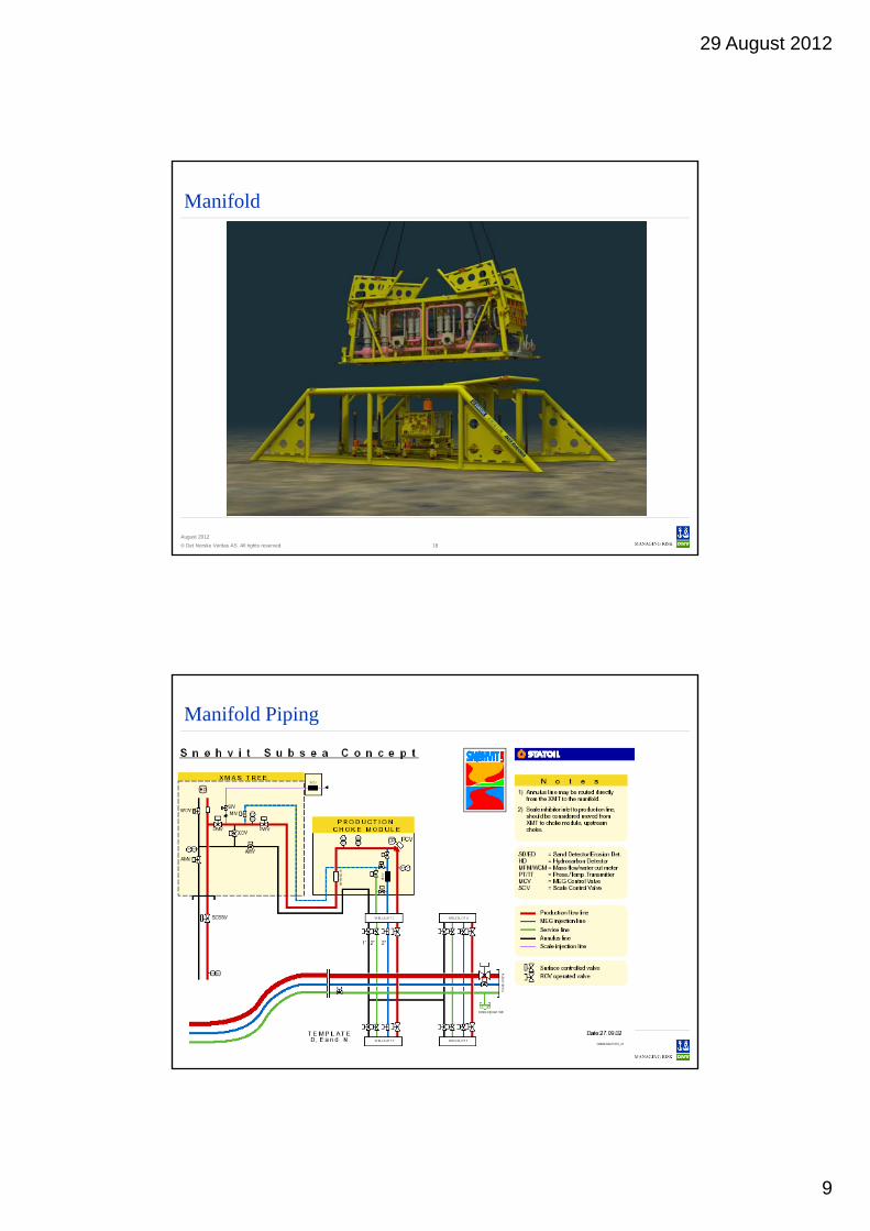
Manifold
© Det Norske Veritas AS. All rights reserved.
August 2012
19
Manifold Piping
29 August 2012
10
© Det Norske Veritas AS. All rights reserved.
August 2012
20
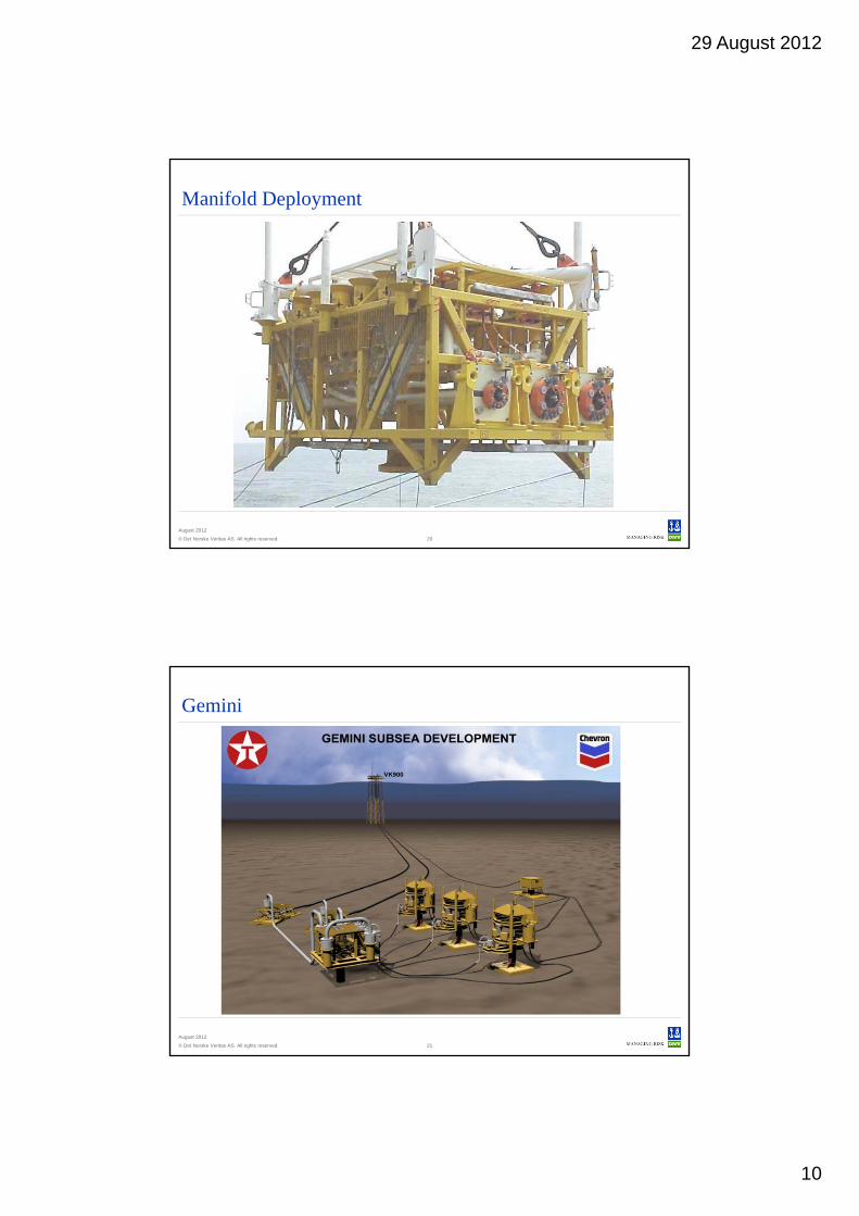
Manifold Deployment
© Det Norske Veritas AS. All rights reserved.
August 2012
21
Gemini
29 August 2012
11
© Det Norske Veritas AS. All rights reserved.
August 2012
22
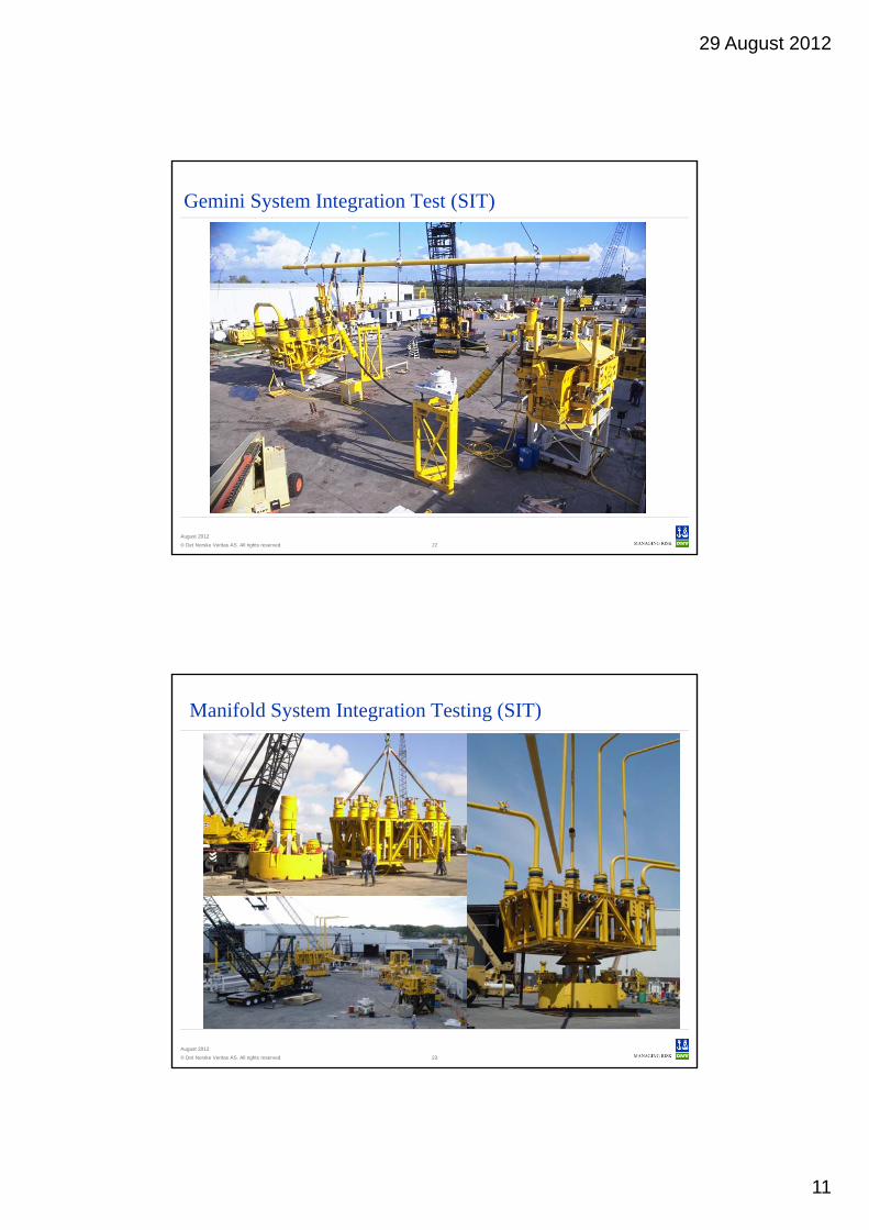
Gemini System Integration Test (SIT)
© Det Norske Veritas AS. All rights reserved.
August 2012
23
Manifold System Integration Testing (SIT)

29 August 2012
12
© Det Norske Veritas AS. All rights reserved.
August 2012
24
Manifold and distribution System
Manifold Centers w/o template function
© Det Norske Veritas AS. All rights reserved.
August 2012
25
Foundations
From ISO 13628-1
1. Riser joint
2. Applied moments
3. Environmental (current, wave action, snag loads, etc.)
4. Flowline connection
5. Soil reaction
6. Thermal
29 August 2012
13
© Det Norske Veritas AS. All rights reserved.
August 2012
26
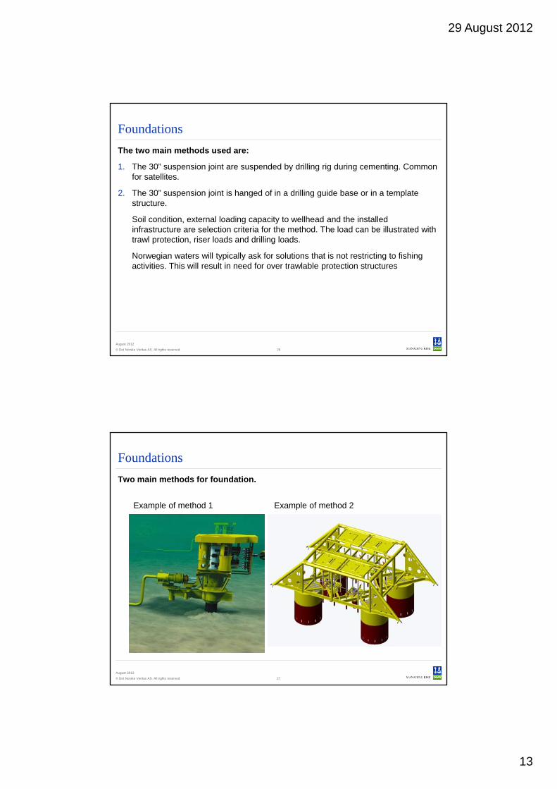
Foundations
The two main methods used are:
1. The 30” suspension joint are suspended by drilling rig during cementing. Common for satellites.
2. The 30” suspension joint is hanged of in a drilling guide base or in a template structure.
Soil condition, external loading capacity to wellhead and the installed infrastructure are selection criteria for the method. The load can be illustrated with trawl protection, riser loads and drilling loads.
Norwegian waters will typically ask for solutions that is not restricting to fishing activities. This will result in need for over trawlable protection structures
© Det Norske Veritas AS. All rights reserved.
August 2012
27
Foundations
Two main methods for foundation.
Example of method 1 Example of method 2
29 August 2012
14
© Det Norske Veritas AS. All rights reserved.
August 2012
28
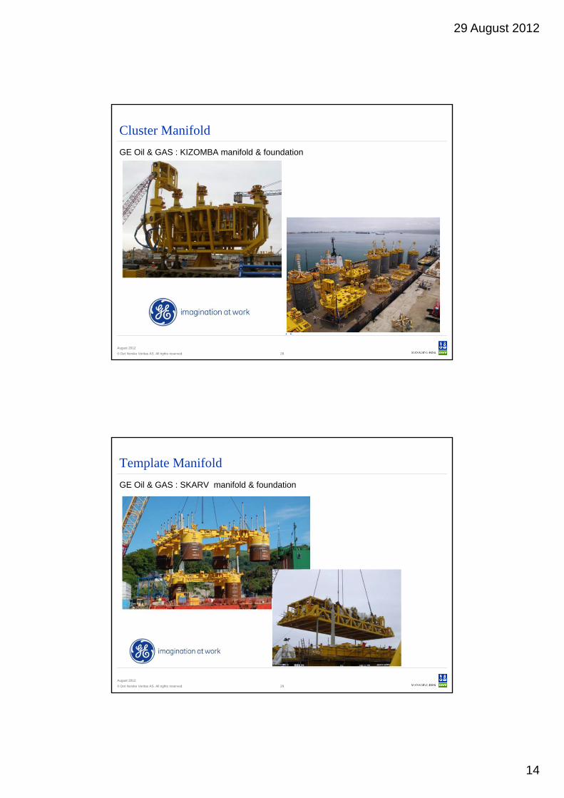
Cluster Manifold
GE Oil & GAS : KIZOMBA manifold & foundation
© Det Norske Veritas AS. All rights reserved.
August 2012
29
Template Manifold
GE Oil & GAS : SKARV manifold & foundation

29 August 2012
15
© Det Norske Veritas AS. All rights reserved.
August 2012
30
Template Manifold
GE Oil & GAS : Snøhvit manifold & foundation
© Det Norske Veritas AS. All rights reserved.
August 2012
31
Safeguarding life, property and the environment
www.dnv.com
Top Related