


Languages
Pages
Legal


MARU 220 Doppler VHF Omni-directional Radio Range
Technical Manual
Volume II
OPERATIONS AND MAINTENANCE
INSTALLATION
Copyright (C) 2009-2011
MOPIENS, Inc.
www.mopiens.com

Table of Contents
Copyright© 2009-2011 MOPIENS, Inc. All Rights Reserved. Page III
CHAPTER 1. RMMS/LMMS .............................................................................. 1-1
1.1. RMMS/LMMS overview ...................................................................................1-1
1.2. Software installation .......................................................................................1-2
1.3. Communication connection ...........................................................................1-5
1.4. Log-in ...............................................................................................................1-8
1.5. Main window .................................................................................................. 1-11
1.5.1. Main window description ......................................................................................1-11
1.5.2. Menu Bar ............................................................................................................ 1-15
1.6. Transmitter window ...................................................................................... 1-16
1.6.1. Transmitter window description .......................................................................... 1-16
1.6.2. Transmitter menu ................................................................................................ 1-29
1.7. Monitor window ............................................................................................. 1-30
1.7.1. Main monitor window description ....................................................................... 1-30
1.7.2. Monitor Expansion Window Description ............................................................. 1-34
1.7.3. Monitor Menu ...................................................................................................... 1-35
1.8. System window ............................................................................................. 1-36
1.8.1. System window Description ................................................................................ 1-36
1.9. Log Data Management Window .................................................................... 1-41
1.9.1. Log Data Management Window Description ...................................................... 1-41
1.9.2. Log Data Format ................................................................................................. 1-43
1.9.3. Measure Item Record Data ................................................................................. 1-52
1.10. Program Menu ............................................................................................... 1-54
1.10.1. File Menu ............................................................................................................ 1-54
1.10.2. Window Menu ..................................................................................................... 1-55
1.10.3. Calibration Menu ................................................................................................. 1-56
1.10.4. Tool Menu ........................................................................................................... 1-58
CHAPTER 2. CSP ............................................................................................. 2-1
2.1. CSP Overview ..................................................................................................2-1
2.2. CSP exterior configuration .............................................................................2-1
2.2.1. Control & Silence .................................................................................................. 2-1
2.2.2. Transmitter Lamp .................................................................................................. 2-2
2.2.3. Monitor Lamp ........................................................................................................ 2-2
Operations and Maintenance / Ed.01
Copyright© 2009-2011 MOPEINS, Inc. All Rights Reserved Page IV
2.3. Characteristics of CSP ....................................................................................2-3
2.3.1. Quick Menu ..........................................................................................................2-11
2.3.2. Alarm ................................................................................................................... 2-12
2.3.3. Transmitter .......................................................................................................... 2-20
2.3.4. Monitor ................................................................................................................ 2-34
2.3.5. 2.3.5 System ....................................................................................................... 2-49
2.3.6. Power Supply ...................................................................................................... 2-68
2.3.7. Information .......................................................................................................... 2-72
CHAPTER 3. OPERATION ............................................................................... 3-1
3.1. Overview ..........................................................................................................3-1
3.2. Equipment Power On & Power Off .................................................................3-1
3.3. Bypassing Monitors ........................................................................................3-2
3.4. Using LMMS/RMMS .........................................................................................3-2
3.5. Using CSP/RCMU ............................................................................................3-2
CHAPTER 4. MAINTENANCE .......................................................................... 4-1
4.1. Overview ..........................................................................................................4-1
4.2. Preventive Maintenance Schedule .................................................................4-1
4.3. Preventive Maintenance Procedure ...............................................................4-2
4.3.1. Tools and Test Equipments Required ................................................................... 4-2
4.3.2. Checking System Status ....................................................................................... 4-2
4.3.3. Checking Carrier/Sideband RF Frequency ........................................................... 4-2
4.3.4. Checking Carrier Modulation Waveform ............................................................... 4-3
4.3.5. Checking Site Environment .................................................................................. 4-3
4.3.6. Checking Carrier Output Power ............................................................................ 4-3
4.3.7. Checking Sideband Output Power ....................................................................... 4-3
4.3.8. Checking site IDENT ............................................................................................ 4-4
4.3.9. Checking Antenna VSWR ..................................................................................... 4-4
4.3.10. Checking Backup Battery ..................................................................................... 4-4
4.3.11. Checking Automatic Transmitter Changeover ...................................................... 4-5
4.3.12. Switching Main / Standby Transmitter .................................................................. 4-5
4.3.13. Checking Antenna Element and Radome ............................................................. 4-5
4.3.14. Checking Monitor Antenna.................................................................................... 4-5
4.3.15. Checking Monitor Parameters .............................................................................. 4-5
CHAPTER 5. INSTALLATION .......................................................................... 5-1
5.1. SELECTING INSTALLATION SITE ..................................................................5-1
5.2. FOUNDATIONS FOR DVOR COUNTERPOISE AND SHELTER......................5-2
5.3. GROUNDING ....................................................................................................5-3
Operations and Maintenance / Ed.01
Copyright© 2009-2011 MOPEINS, Inc. All Rights Reserved Page V
5.3.1. General ................................................................................................................. 5-3
5.3.2. Strip or mesh Ground Conductors ........................................................................ 5-3
5.3.3. Ground Rods ........................................................................................................ 5-4
5.3.4. Ground Plates ....................................................................................................... 5-4
5.3.5. Estimating the Ground Resistance ....................................................................... 5-5
5.3.6. Measuring the Ground Resistance ....................................................................... 5-5
5.4. INSTALLING EQUIPMENT SHELTER ..............................................................5-7
5.4.1. General ................................................................................................................. 5-7
5.4.2. Installing Equipment Shelter ................................................................................. 5-7
5.5. INSTALLING ANTENNAS ................................................................................5-8
5.5.1. General ................................................................................................................. 5-8
5.5.2. Antenna mounting ................................................................................................. 5-9
5.5.3. RF Cabling of Antennas ...................................................................................... 5-10
5.5.4. Aligning Sideband Antennas ................................................................................5-11
5.5.5. Installing Field Monitor Antenna.......................................................................... 5-12
5.6. INSTALLING DVOR EQUIPMENTS ............................................................... 5-13
5.6.1. General ............................................................................................................... 5-13
5.6.2. Connecting Power Supply .................................................................................. 5-13
5.6.3. Installing ASU...................................................................................................... 5-14
5.6.4. Connecting External Equipments ....................................................................... 5-16
Operations and Maintenance / Ed.01
Copyright© 2009-2011 MOPEINS, Inc. All Rights Reserved Page VI
Contents of Figures
Figure 1-1 MARU 220 Software Installation Initiation Window .......................................... 1-2
Figure 1-2 MARU 220 Software Installation Window ........................................................ 1-2
Figure 1-3 Program Installation Directory Selection Window ............................................ 1-3
Figure 1-4 Program Menu Folder Selection Window ........................................................ 1-3
Figure 1-5 Program Installation Progress Window ............................................................ 1-4
Figure 1-6 Program Installation Finish Window ................................................................. 1-4
Figure 1-7 Communication Connection Window ............................................................... 1-5
Figure 1-8 Communication Setup Window ........................................................................ 1-6
Figure 1-9 Communication Setup Add Window ................................................................. 1-7
Figure 1-10 Login Window ................................................................................................. 1-8
Figure 1-11 Main Window ................................................................................................. 1-11
Figure 1-12 Unit Status .................................................................................................... 1-13
Figure 1-13 Active/Standby Status of CMA and SMA ...................................................... 1-13
Figure 1-14 PDC Status Indication .................................................................................. 1-13
Figure 1-15 Menu Bar ...................................................................................................... 1-15
Figure 1-16 Transmitter Window ..................................................................................... 1-16
Figure 1-17 Transmitter Status Information ..................................................................... 1-17
Figure 1-18 Frequency Status Display ............................................................................ 1-18
Figure 1-19 Operation Frequency Setup ......................................................................... 1-19
Figure 1-20 Modulation Depth Display ............................................................................ 1-20
Figure 1-21 Modulation Depth Setup ............................................................................... 1-20
Figure 1-22 Sideband RF Phase Display ........................................................................ 1-21
Figure 1-23 Sideband RF Phase Setup........................................................................... 1-21
Figure 1-24 Azimuth Offset Display ................................................................................. 1-22
Figure 1-25 Azimuth Offset Setup ................................................................................... 1-22
Figure 1-26 Modulation Status Display ............................................................................ 1-23
Figure 1-27 Modulation ON/OFF Setup ........................................................................... 1-23
Figure 1-28 Output Power Display .................................................................................. 1-24
Figure 1-29 Output Power Setup ..................................................................................... 1-24
Figure 1-30 IDENT Signal Display ................................................................................... 1-25
Figure 1-31 IDENT Setup ................................................................................................ 1-25
Figure 1-32 Antenna Status Display ................................................................................ 1-26
Figure 1-33 Antenna Status Setup ................................................................................... 1-26
Figure 1-34 Modulation Amp Status Display.................................................................... 1-27
Figure 1-35 Modulation AMP On/Off Setup ..................................................................... 1-27
Figure 1-36 Temperature Display .................................................................................... 1-28
Figure 1-37 Main Monitor Window ................................................................................... 1-30
Figure 1-38 General Status Information .......................................................................... 1-30
Figure 1-39 Normal/Bypass Mode Setup ........................................................................ 1-31
Figure 1-40 Changeover .................................................................................................. 1-31
Operations and Maintenance / Ed.01
Copyright© 2009-2011 MOPEINS, Inc. All Rights Reserved Page VII
Figure 1-41 Measured Value Display .............................................................................. 1-32
Figure 1-42 Alarm Range Setup ...................................................................................... 1-32
Figure 1-43 Azimuth Alarm Range Setup Window .......................................................... 1-33
Figure 1-44 MON Configuration ...................................................................................... 1-33
Figure 1-45 Monitor Expansion Window .......................................................................... 1-34
Figure 1-46 System Window ........................................................................................... 1-36
Figure 1-47 LCU General Information Display ................................................................ 1-36
Figure 1-48 Normal/Bypass Setup .................................................................................. 1-37
Figure 1-49 Alarm Sound Setup Window ........................................................................ 1-37
Figure 1-50 Alarm Sound Setup ...................................................................................... 1-38
Figure 1-51 Auto FAN Control ......................................................................................... 1-38
Figure 1-52 Manual FAN Control ..................................................................................... 1-39
Figure 1-53 Changeover .................................................................................................. 1-40
Figure 1-54 System Reset ............................................................................................... 1-40
Figure 1-55 History Log Window ..................................................................................... 1-41
Figure 1-56 Program Menu ............................................................................................. 1-54
Figure 1-57 File Menu ...................................................................................................... 1-54
Figure 1-58 Window Menu............................................................................................... 1-55
Figure 1-59 Calibration Menu .......................................................................................... 1-56
Figure 1-60 MON Calibration ........................................................................................... 1-56
Figure 1-61 TX Calibration ............................................................................................... 1-57
Figure 1-62 Tool Menu ..................................................................................................... 1-58
Figure 1-63 Account Create ............................................................................................. 1-60
Figure 1-64 Account Delete ............................................................................................. 1-60
Figure 2-65 Front of CSP of MARU 220 System ............................................................... 2-1
Figure 2-66 Main Screen Composition ........................................................................... 2-3
Figure 2-67 MSG1 Power Off Notice Message Screen .................................................. 2-6
Figure 2-68 Alarm Silence Null Message Screen ........................................................... 2-7
Figure 2-69 Setup Application Complete Screen .............................................................. 2-7
Figure 2-70 Changeover Question Message Screen ........................................................ 2-8
Figure 2-71 Text Line Setup Message Screen .................................................................. 2-9
Figure 2-72 Non-Decimal Based Number Value Setup Message Screen ...................... 2-9
Figure 2-73 Decimal Based Number Value Setup Message ........................................ 2-10
Figure 2-74 Setup Message Screen in Case that It is not Number or Text Line ............. 2-10
Figure 2-75 Quick Menu Screen ....................................................................................... 2-11
Figure 2-76 Alarm Menu Screen ...................................................................................... 2-12
Figure 2-77 Alarm Menu Structure ................................................................................... 2-13
Figure 2-78 Alarm > Transmitter 1 / 2 Menu Screen ....................................................... 2-14
Figure 2-79 Alarm > Monitor 1 / 2 Menu Screen ............................................................. 2-15
Figure 2-80 Alarm > Presence Detect Screen ................................................................. 2-16
Figure 2-81 Alarm > System Menu Screen ..................................................................... 2-17
Figure 2-82 Alarm > Power Supply Menu Screen ........................................................... 2-18
Figure 2-83 Alarm > Environment Screen ....................................................................... 2-19
Operations and Maintenance / Ed.01
Copyright© 2009-2011 MOPEINS, Inc. All Rights Reserved Page VIII
Figure 2-84 Transmitter Menu Screen ............................................................................. 2-20
Figure 2-85 Transmitter Menu Structure .......................................................................... 2-21
Figure 2-86 Transmitter > TX1 / 2 Menu Screen ............................................................. 2-22
Figure 2-87 Transmitter > TX1 / 2 > Status Menu Screen ............................................... 2-23
Figure 2-88 Transmitter > TX1 / 2 > Power AMP Control Screen ................................... 2-24
Figure 2-89 Transmitter > TX1 / 2 > Output Power Screen ............................................. 2-25
Figure 2-90 Transmitter > TX1 / 2 > Modulation Depth Screen ....................................... 2-26
Figure 2-91 Transmitter > TX1 / 2 > Modulation Control Screen ..................................... 2-27
Figure 2-92 Transmitter > TX1 / 2 > Carrier Frequency Screen ...................................... 2-28
Figure 2-93 Transmitter > TX1 / 2 > Azimuth Offset Screen............................................ 2-29
Figure 2-94 Transmitter > TX1 / 2 > SB RF Phase Offset Screen .................................. 2-30
Figure 2-95 Transmitter > CONFIG Menu Screen ........................................................... 2-31
Figure 2-96 Transmitter > IDENT Setting Screen ............................................................ 2-32
Figure 2-97 Transmitter > Antenna Control Screen ......................................................... 2-33
Figure 2-98 Monitor Menu Screen ................................................................................... 2-34
Figure 2-99 Monitor Menu Structure ................................................................................ 2-35
Figure 2-100 Monitor > MON1 / 2 Menu Screen ............................................................. 2-36
Figure 2-101 Monitor > MON1 / 2 > Status Menu Screen ............................................... 2-37
Figure 2-102 Monitor > MON1 / 2 > Basic Parameters Menu Screen ............................ 2-39
Figure 2-103 Monitor > MON1 / 2 > Extended Parameters Menu Screen ...................... 2-40
Figure 2-104 Monitor > MON1 / 2 > Limits Menu Screen ................................................ 2-41
Figure 2-105 Monitor > CONFIG Menu Screen ............................................................... 2-44
Figure 2-106 Monitor > CONFIG > TSG Control Screen ................................................ 2-44
Figure 2-107 Monitor > CONFIG > Measure Mode Screen ............................................ 2-46
Figure 2-108 Monitor > CONFIG > MON1 Bypass Screen ............................................. 2-47
Figure 2-109 Monitor > CONFIG > MON2 Bypass Screen ............................................. 2-48
Figure 2-110 System Menu Screen ................................................................................. 2-49
Figure 2-111 System Menu Structure .............................................................................. 2-50
Figure 2-112 System > Save & Restore Menu Screen .................................................... 2-51
Figure 2-113 System > System Control Menu Screen .................................................... 2-52
Figure 2-114 System > Changeover Menu Screen ......................................................... 2-53
Figure 2-115 System > Changeover > Auto CHOV Reason (MON1 / 2) Menu Screen .. 2-54
Figure 2-116 System > FAN Control Menu Screen ......................................................... 2-55
Figure 2-117 System > FAN Control > FAN Status Menu Screen ................................... 2-56
Figure 2-118 System > FAN Control > Config Manual Mode Menu Screen .................... 2-57
Figure 2-119 System > FAN Control > Config Auto Mode Menu Screen ........................ 2-58
Figure 2-120 System > Presence Detect Menu Screen .................................................. 2-59
Figure 2-121 System > Temperature Menu Screen ........................................................ 2-60
Figure 2-122 System > Environment Menu Screen ........................................................ 2-62
Figure 2-123 System > Environment > Config Environment Menu Screen .................... 2-63
Figure 2-124 System > Audio Menu Screen .................................................................... 2-64
Figure 2-125 System > DME Interface Menu Screen...................................................... 2-65
Figure 2-126 System > LCU Configuration Menu Screen ............................................... 2-66
Operations and Maintenance / Ed.01
Copyright© 2009-2011 MOPEINS, Inc. All Rights Reserved Page IX
Figure 2-127 System > LCU Configuration > Config COMM Port Menu Screen ............ 2-67
Figure 2-128 Power Supply Menu Screen....................................................................... 2-68
Figure 2-129 Power Supply Menu Structure ................................................................... 2-68
Figure 2-130 Power Supply > PSU Status Menu Screen ................................................ 2-69
Figure 2-131 Power Supply > PSU Measurement Menu Screen .................................... 2-70
Figure 2-132 Information Menu Screen ........................................................................... 2-72
Figure 2-133 Information Menu Structure ........................................................................ 2-73
Figure 2-134 Information > Date & Time Menu Screen ................................................... 2-74
Figure 2-135 Information > Date & Time > System Date Menu Screen .......................... 2-75
Figure 2-136 Information > Date & Time > System Time Menu Screen .......................... 2-76
Figure 2-137 Information > LCU Menu Screen ............................................................... 2-77
Figure 2-138 Information > MSG1 / 2 Menu Screen ....................................................... 2-78
Figure 2-139 Information > MON1 / 2 Menu Screen ....................................................... 2-79
Operations and Maintenance / Ed.01
Copyright© 2009-2011 MOPEINS, Inc. All Rights Reserved Page X
Contents of Tables
Table 1-1 Rights by User Level ........................................................................................ 1-10
Table 1-2 Basic Status Information Display Content ....................................................... 1-17
Table 1-3 Frequency Display Content ............................................................................. 1-18
Table 1-4 Frequency Setup Range .................................................................................. 1-19
Table 1-5 Modulation Depth Setup Range....................................................................... 1-20
Table 1-6 Sideband RF Phase Setup Range .................................................................. 1-21
Table 1-7 Azimuth Offset Setup Range ........................................................................... 1-22
Table 1-8 Modulation Control Display Content ................................................................ 1-23
Table 1-9 Output Setup Range ........................................................................................ 1-24
Table 1-10 IDENT Display Content .................................................................................. 1-25
Table 1-11 Antenna Control Mode Display Content ......................................................... 1-26
Table 1-12 Modulation Amp Display Content................................................................... 1-27
Table 1-13 Basic Status Information Display Content ..................................................... 1-30
Table 2-14 Alarm > Transmitter 1 / 2 Display Item ........................................................... 2-14
Table 2-15 Alarm > Monitor 1 / 2 Display Item ................................................................. 2-15
Table 2-16 Alarm > Presence Detect Display Item .......................................................... 2-16
Table 2-17 Alarm > System Display Item ......................................................................... 2-17
Table 2-18 Alarm > Power Supply Display Item .............................................................. 2-18
Table 2-19 Alarm > Environment Display Item ................................................................ 2-19
Table 2-20 Transmitter Display Item ................................................................................ 2-20
Table 2-21 Transmitter > TX1 / 2 Display Item ................................................................ 2-22
Table 2-22 Transmitter > TX1 / 2 > Status Display Item .................................................. 2-23
Table 2-23 Transmitter > TX1 / 2 > Power AMP Control Setup Item ............................... 2-24
Table 2-24 Transmitter > TX1 / 2 > Output Power Setup Item ........................................ 2-25
Table 2-25 Transmitter > TX1 / 2 > Modulation Depth Setup Item .................................. 2-26
Table 2-26 Transmitter > TX1 / 2 > Modulation Control Setup Item ................................ 2-27
Table 2-27 Transmitter > TX1 / 2 > Carrier Frequency Setup Item ................................. 2-28
Table 2-28 Transmitter > TX1 / 2 > Azimuth Offset Setup Item ....................................... 2-29
Table 2-29 Transmitter > CONFIG Display Item .............................................................. 2-31
Table 2-30 Transmitter > IDENT Setting Setup Item ....................................................... 2-32
Table 2-31 Transmitter > Antenna Control Setup Item .................................................... 2-33
Table 2-32 Monitor Sub Menu ......................................................................................... 2-34
Table 2-33 Monitor > MON1 / 2 Display Item .................................................................. 2-36
Table 2-34 Monitor > MON1 / 2 > Status Display Item .................................................... 2-37
Table 2-35 Monitor > MON1 / 2 > Basic Parameters Display Item .................................. 2-39
Table 2-36 Monitor > MON1 / 2 > Extended Parameters Display Item ........................... 2-40
Table 2-37 Monitor > MON1 / 2 > Limits Display Item ..................................................... 2-41
Table 2-38 Monitor > CONFIG Display Item .................................................................... 2-44
Table 2-39 Monitor > CONFIG > TSG Control Setup Item .............................................. 2-45
Table 2-40 TSG Signal Item ............................................................................................. 2-45
Operations and Maintenance / Ed.01
Copyright© 2009-2011 MOPEINS, Inc. All Rights Reserved Page XI
Table 2-41 Monitor > CONFIG > Measure Mode Setup Item .......................................... 2-46
Table 2-42 Monitor > CONFIG > MON1 Bypass Setup Item ........................................... 2-47
Table 2-43 Monitor > CONFIG > MON2 Bypass Setup Item ........................................... 2-48
Table 2-44 System Display Item ...................................................................................... 2-49
Table 2-45 System > Save & Restore Display Item ......................................................... 2-51
Table 2-46 System >System Control Display Item .......................................................... 2-52
Table 2-47 System > Changeover Display Item .............................................................. 2-53
Table 2-48 System > Changeover > Auto CHOV Reason (MON1 / 2) Display Item ....... 2-54
Table 2-49 System > FAN Control Display Item .............................................................. 2-55
Table 2-50 System > FAN Control > FAN Status Display Item ........................................ 2-56
Table 2-51 System > FAN Control > Config Manual Mode Display Item ......................... 2-57
Table 2-52 System > FAN Control > Config Auto Mode Display Item ............................. 2-58
Table 2-53 System > Presence Detect Display Item ....................................................... 2-59
Table 2-54 System > Temperature Display Item .............................................................. 2-60
Table 2-55 System > Environment Display Item .............................................................. 2-62
Table 2-56 System > Environment > Config Environment Display Item .......................... 2-63
Table 2-57 System > Audio Display Item ......................................................................... 2-64
Table 2-58 System > DME Interface Display Item ........................................................... 2-65
Table 2-59 System > LCU Configuration Display Item .................................................... 2-66
Table 2-60 System > LCU Configuration > Config COMM Port Display Item ................. 2-67
Table 2-61 Power Supply Display Item ............................................................................ 2-68
Table 2-62 Power Supply > PSU Status Display Item ..................................................... 2-69
Table 2-63 Power Supply > PSU Measurement Display Item ......................................... 2-70
Table 2-64 Information Display Item ................................................................................ 2-72
Table 2-65 Information > Date & Time Display Item ........................................................ 2-74
Table 2-66 Information > Date & Time > System Date Setup Item ................................. 2-75
Table 2-67 Information > Date & Time > System Time Setup Item ................................. 2-76
Table 2-68 Information > LCU Display Item ..................................................................... 2-77
Table 2-69 Information > MSG1 / 2 Display Item ............................................................. 2-78
Table 2-70 Information > MON1 / 2 Display Item ............................................................ 2-79
Operations and Maintenance / Ed.01
Copyright© 2009-2011 MOPEINS, Inc. All Rights Reserved Page XII
Abbreviations
ADC Analog to Digital Converter
AES Antenna Electronics Subsystem
AMP Amplifier
ANT Antenna
ASU Antenna Switching Unit
BIT Built In Test
BITE Built In Test Equipment
BPF Band Pass Filter
CMA Carrier Modulation Amplifier
CMS Control Monitor Subsystem
CPA Carrier Power Amplifier
CPD Carrier Power Detector
CSP Control and Status Panel
CSU Control Selection Unit
CVOR Conventional VOR
DAC Digital to Analog Converter
DET Detector
DME Distance Measuring Equipment
DPDT Double-Pole Double-Throw
DVOR Doppler VOR
ENV Envelope
GUI Graphic User Interface
LCU Local Control Unit
LPF Low Pass Filter
LSB Lower Sideband
MAS Modulation Amplifier Subsystem
MOD Modulator
MISC MISCellaneous
MMIC Monolithic Microwave Integrated Circuit
MOD Modulator
MON Monitor
MSG Modulation Signal Generator
PA Power Amplifier
PDC Power Detector &Changeover
PFC Phase Frequency Comparator
PLD Programmable Logic Device
PLL Phase Locked Loop
PSS Power Supply Subsystem
PSU Power Supply Unit
PWM Pulse-Width Modulation
Operations and Maintenance / Ed.01
Copyright© 2009-2011 MOPEINS, Inc. All Rights Reserved Page XIII
RCMU Remote Control and Monitor Unit
REF CLK Reference Clock
RMU Remote Monitor Unit
SBA Sideband Amplifier Unit
SM Selection Module
SMA Sideband Modulation Amplifier
SPD Sideband Power Detector
SPI Serial Peripheral Interface
SYN Synthesizer
TACAN Tactical Air Navigation System
TCXO Temperature Compensated Crystal Oscillator
TM Toggling Module
UART Universal Asynchronous Receiver/Transmitter
USART Universal Synchronous/Asynchronous Receiver/Transmitter
USB Upper Sideband
VOP Voice Processor
VSWR Voltage Standing Wave Ratio

Operations and Maintenance / Ed.01
Copyright© 2009-2011 MOPEINS, Inc. All Rights Reserved Page XIV
Chapter 1. RMMS/LMMS
Copyright© 2009-2011 MOPIENS, Inc. All Rights Reserved Page 1-1
Chapter 1. RMMS/LMMS
1.1. RMMS/LMMS overview
Remote Maintenance Monitoring System (RMMS) or Local Maintenance Monitoring
System (LMMS) is a program that enables users to monitor or control MARU 220
system on PCs. The RMMS/LMMS can be directly connected through the use of
Local Control Unit (LCU) and serial cables and remotely accessed through the use of
modems.
The RMMS/LMMS controls the status of TX and reads the values measured on MON
to display them on the monitor of a PC. The information is the same as what is
displayed on the Control Status Panel (CSP) of the MARU 220 system.
Representative status information displayed on the PC monitor is as follows.
Alarm measured in each unit
Plug-in status of each unit
Measured main parameters of DVOR signal
Control of main parameters of DVOR signal
History log
Main functions of each window are as follows.
Log-in window: It is a user authentication window to control the MARU 220
System. Only authenticated users can control the system by entering a user account
and a password. Only status reference is allowed in communication connection
without log-in.
Main window: It has been designed to view major parameters among values
measured by the MARU 220 System and conveniently figure out fault status in the
unit. The unit where alarm occurred is indicated as red, and if the unit is clicked, it
switches to the window of the unit or displays information on the unit.
TX window: It controls the signal of MARU 220 Transmitter. It can control general
signals such as frequency setup and output power setup and provides functions for
antenna tests.
MON window: It displays parameters measured in MON unit and can set up the
range of alarms with regard to measured items.
History log window: LCU saves alarm occurrence status of the values measured in
MON and information on the transmitter control item changed in MSG. The log
data are save not only in LCU but also in a local folder of a RMMS/LMMS PC,
and history log window displays log records saved in the LCU and the PC. Inquiry
can be made by date or in order of the latest record.
System window: It provides such general control items required to operate the
system as Changeover, System reset, FAN control and System sound setup.
Chapter 1. RMMS/LMMS
Copyright© 2009-2011 MOPIENS, Inc. All Rights Reserved Page 1-2
1.2. Software installation
A PC should have following specifications to install MARU 220 RMMS/LMMS
software.
Distinction Specifications
System IBM Compatible PC : Desktop or Laptop
CPU Intel Pentium 133MHz or Higher
Memory Minimum 64MB RAM
HDD Minimum 2GB (650MB or more)
Operating System Microsoft Windows 2000/XP
RMMS/LMMS software is installed in accordance with following procedures.
If you insert a RMMS program CD into a PC, following installation initiation window
appears. If the installation initiation window does not appear automatically, execute
‘Setup.exe’.
Figure 1-1 MARU 220 Software Installation Initiation Window
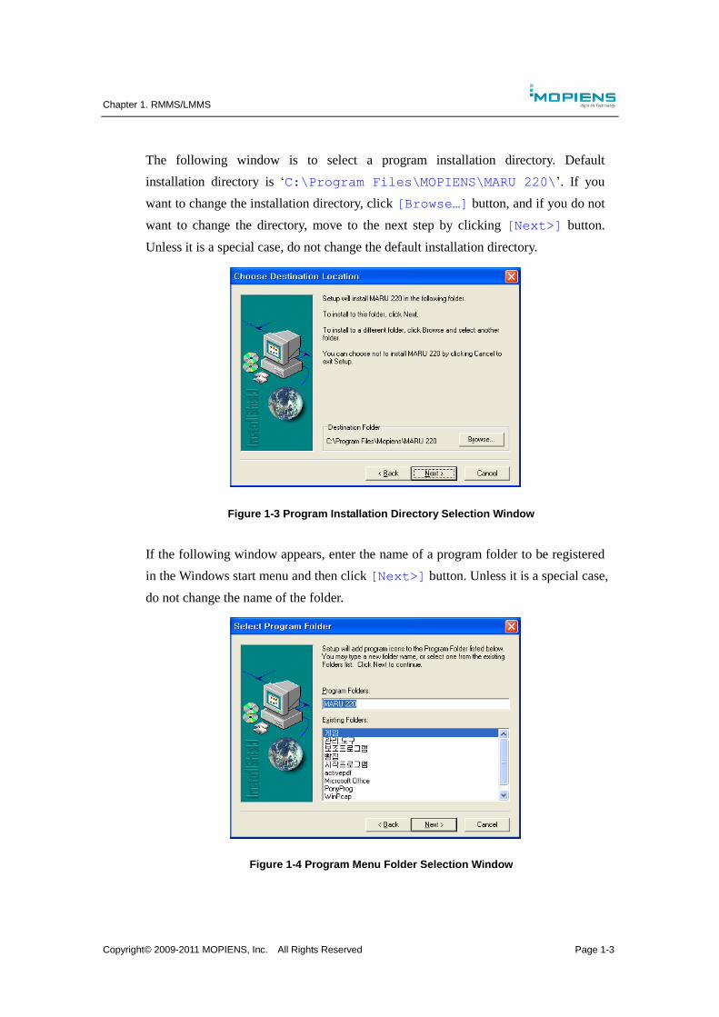
If following installation window appears, click [Next>] button.
Figure 1-2 MARU 220 Software Installation Window
Chapter 1. RMMS/LMMS
Copyright© 2009-2011 MOPIENS, Inc. All Rights Reserved Page 1-3
The following window is to select a program installation directory. Default
installation directory is ‘C:\Program Files\MOPIENS\MARU 220\’. If you
want to change the installation directory, click [Browse…] button, and if you do not
want to change the directory, move to the next step by clicking [Next>] button.
Unless it is a special case, do not change the default installation directory.
Figure 1-3 Program Installation Directory Selection Window
If the following window appears, enter the name of a program folder to be registered
in the Windows start menu and then click [Next>] button. Unless it is a special case,
do not change the name of the folder.
Figure 1-4 Program Menu Folder Selection Window
Chapter 1. RMMS/LMMS
Copyright© 2009-2011 MOPIENS, Inc. All Rights Reserved Page 1-4
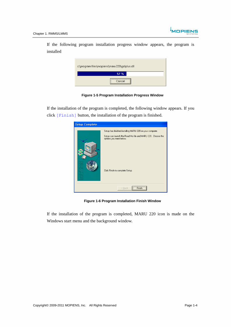
If the following program installation progress window appears, the program is
installed
Figure 1-5 Program Installation Progress Window
If the installation of the program is completed, the following window appears. If you
click [Finish] button, the installation of the program is finished.
Figure 1-6 Program Installation Finish Window
If the installation of the program is completed, MARU 220 icon is made on the
Windows start menu and the background window.
Chapter 1. RMMS/LMMS
Copyright© 2009-2011 MOPIENS, Inc. All Rights Reserved Page 1-5
1.3. Communication connection
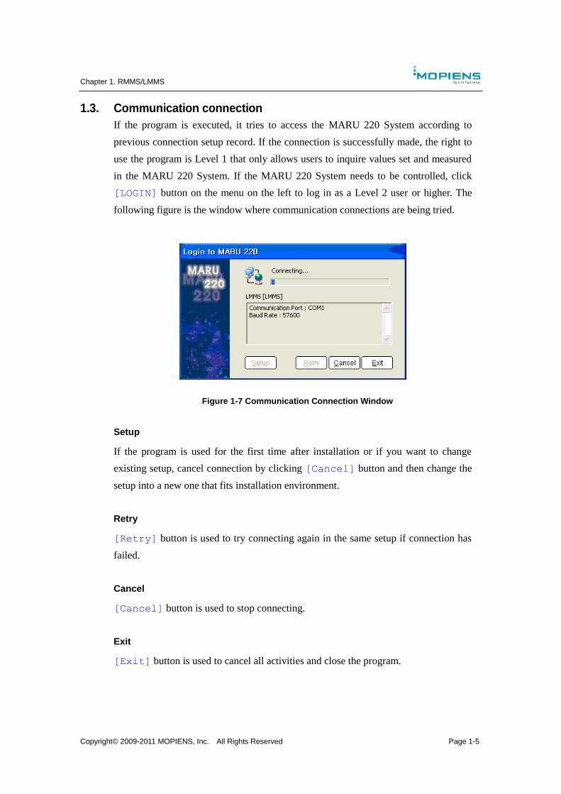
If the program is executed, it tries to access the MARU 220 System according to
previous connection setup record. If the connection is successfully made, the right to
use the program is Level 1 that only allows users to inquire values set and measured
in the MARU 220 System. If the MARU 220 System needs to be controlled, click
[LOGIN] button on the menu on the left to log in as a Level 2 user or higher. The
following figure is the window where communication connections are being tried.
Figure 1-7 Communication Connection Window
Setup
If the program is used for the first time after installation or if you want to change
existing setup, cancel connection by clicking [Cancel] button and then change the
setup into a new one that fits installation environment.
Retry
[Retry] button is used to try connecting again in the same setup if connection has
failed.
Cancel
[Cancel] button is used to stop connecting.
Exit
[Exit] button is used to cancel all activities and close the program.
Chapter 1. RMMS/LMMS
Copyright© 2009-2011 MOPIENS, Inc. All Rights Reserved Page 1-6
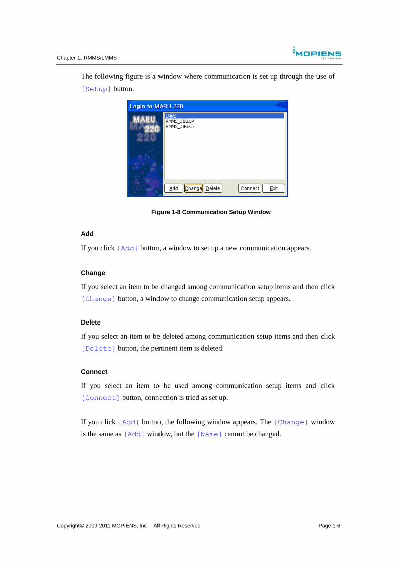
The following figure is a window where communication is set up through the use of
[Setup] button.
Figure 1-8 Communication Setup Window
Add
If you click [Add] button, a window to set up a new communication appears.
Change
If you select an item to be changed among communication setup items and then click
[Change] button, a window to change communication setup appears.
Delete
If you select an item to be deleted among communication setup items and then click
[Delete] button, the pertinent item is deleted.
Connect
If you select an item to be used among communication setup items and click
[Connect] button, connection is tried as set up.
If you click [Add] button, the following window appears. The [Change] window
is the same as [Add] window, but the [Name] cannot be changed.
Chapter 1. RMMS/LMMS
Copyright© 2009-2011 MOPIENS, Inc. All Rights Reserved Page 1-7
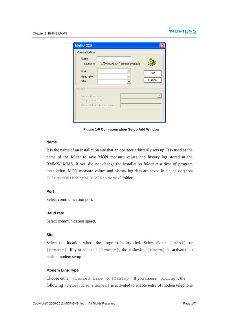
Figure 1-9 Communication Setup Add Window
Name
It is the name of an installation site that an operator arbitrarily sets up. It is used as the
name of the folder to save MON measure values and history log stored in the
RMMS/LMMS. If you did not change the installation folder at a time of program
installation, MON measure values and history log data are saved in ‘C:\Program
Files\MOPIENS\MARU 220\<Name>’ folder
Port
Select communication port.
Baud rate
Select communication speed.
Site
Select the location where the program is installed. Select either [Local] or
[Remote]. If you selected [Remote], the following [Modem] is activated to
enable modem setup.
Modem Line Type
Choose either [Leased Line] or [Dialup]. If you choose [Dialup], the
following [Telephone number] is activated to enable entry of modem telephone

Chapter 1. RMMS/LMMS
Copyright© 2009-2011 MOPIENS, Inc. All Rights Reserved Page 1-8
number for destination..
Telephone number
Enter modem telephone number to be connected.
Modem Initialization command
Enter model control command in the AT Command format. Since it aims to test a
modem, leave it as a blank space.
1.4. Log-in
If the connection is successfully made, the program moves to the main window. At
that time, it is a level 1 security status that only allows users to inquire the MARU
220 System. If you need to control the MARU 220 System, you must log in again as a
level-2 user or higher. You can log in as a higher-level user by clicking [LOGIN]
button on the menu on the left of the program.
Security levels range from level 1 through level 3, and the level 3 is the highest. The
security level, ID, password are saved in the LCU unit of the MARU 220 System.
Figure 1-10 Login Window
Security level
It is divided into followings in accordance with the security level of RMMS/LMMS
system operators, and functions are limited by level.
Level 1: It is possible to inquire Main window, MON window, TX window and
System.
Level 2: It is possible to control Main window, MON window, TX window, TX
control, MON control and Changeover.
Level 3: It is possible to manage Main window, MON window, TX window, TX

Chapter 1. RMMS/LMMS
Copyright© 2009-2011 MOPIENS, Inc. All Rights Reserved Page 1-9
control, MON control, Changeover, History Log data and create/delete user
account.
Chapter 1. RMMS/LMMS
Copyright© 2009-2011 MOPIENS, Inc. All Rights Reserved Page 1-10
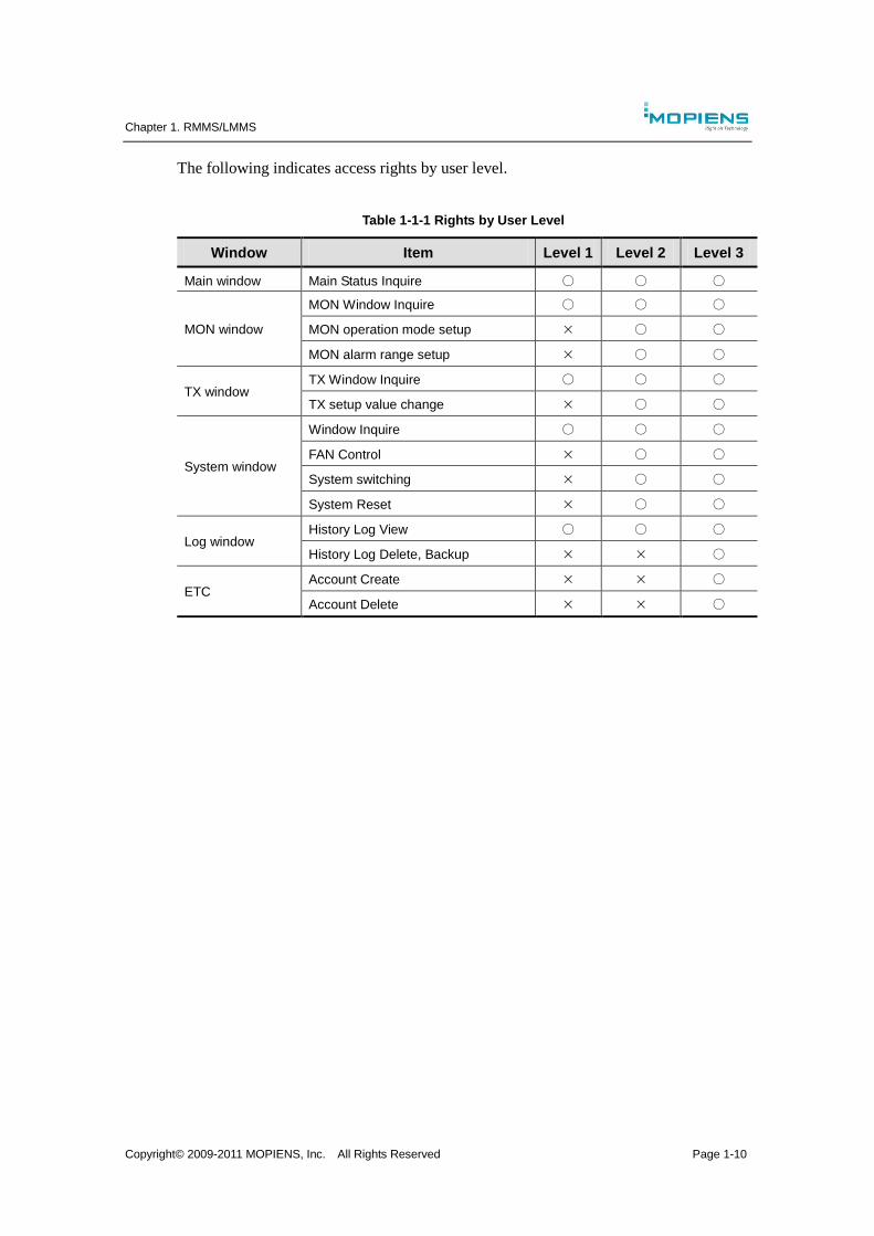
The following indicates access rights by user level.
Table 1-1-1 Rights by User Level
Window Item Level 1 Level 2 Level 3
Main window Main Status Inquire ○ ○ ○
MON window
MON Window Inquire ○ ○ ○
MON operation mode setup × ○ ○
MON alarm range setup × ○ ○
TX window TX Window Inquire ○ ○ ○
TX setup value change × ○ ○
System window
Window Inquire ○ ○ ○
FAN Control × ○ ○
System switching × ○ ○
System Reset × ○ ○
Log window History Log View ○ ○ ○
History Log Delete, Backup × × ○
ETC Account Create × × ○
Account Delete × × ○
Chapter 1. RMMS/LMMS
Copyright© 2009-2011 MOPIENS, Inc. All Rights Reserved Page 1-11
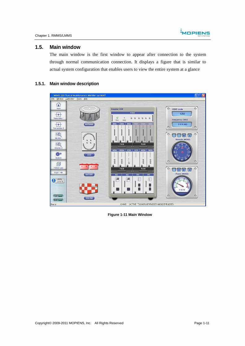
1.5. Main window
The main window is the first window to appear after connection to the system
through normal communication connection. It displays a figure that is similar to
actual system configuration that enables users to view the entire system at a glance
1.5.1. Main window description
Figure 1-11 Main Window
Chapter 1. RMMS/LMMS
Copyright© 2009-2011 MOPIENS, Inc. All Rights Reserved Page 1-12
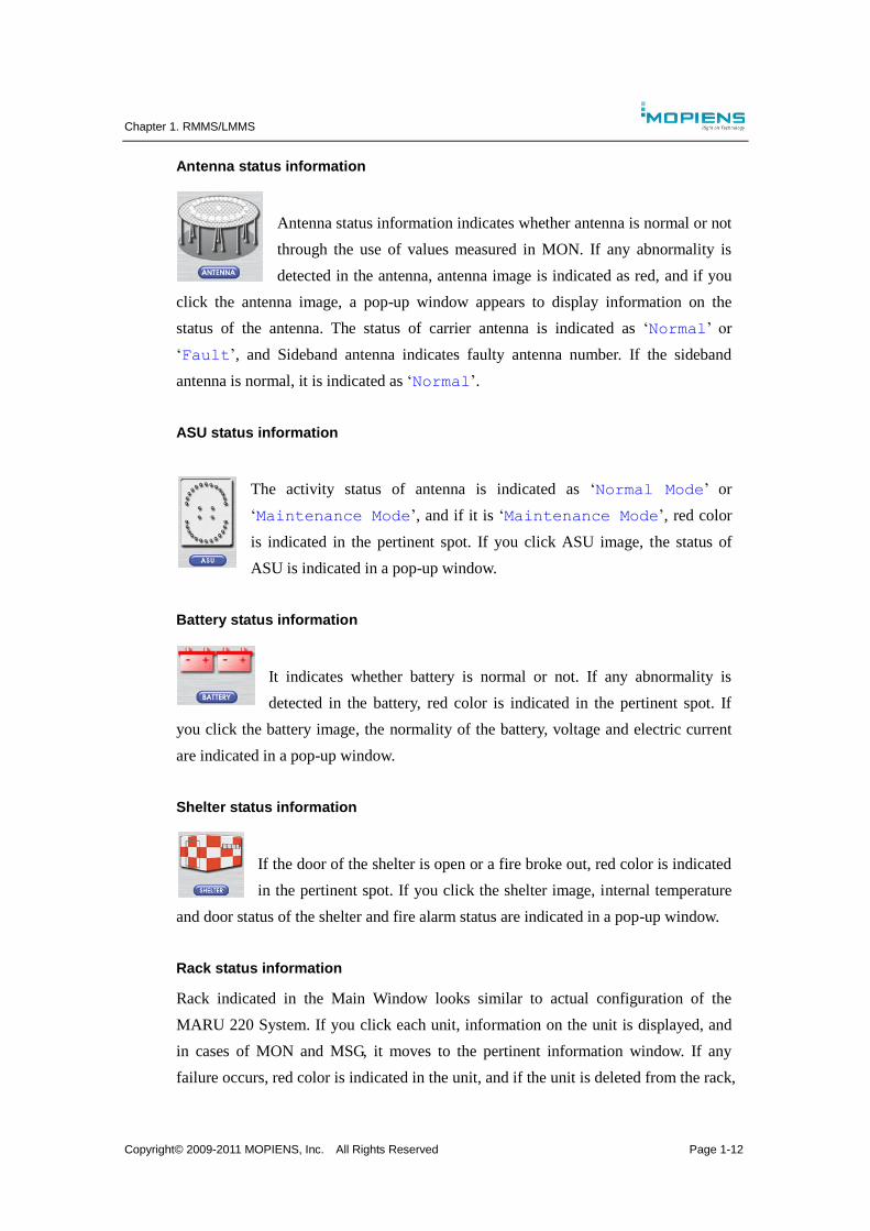
Antenna status information
Antenna status information indicates whether antenna is normal or not
through the use of values measured in MON. If any abnormality is
detected in the antenna, antenna image is indicated as red, and if you
click the antenna image, a pop-up window appears to display information on the
status of the antenna. The status of carrier antenna is indicated as ‘Normal’ or
‘Fault’, and Sideband antenna indicates faulty antenna number. If the sideband
antenna is normal, it is indicated as ‘Normal’.
ASU status information
The activity status of antenna is indicated as ‘Normal Mode’ or
‘Maintenance Mode’, and if it is ‘Maintenance Mode’, red color
is indicated in the pertinent spot. If you click ASU image, the status of
ASU is indicated in a pop-up window.
Battery status information
It indicates whether battery is normal or not. If any abnormality is
detected in the battery, red color is indicated in the pertinent spot. If
you click the battery image, the normality of the battery, voltage and electric current
are indicated in a pop-up window.
Shelter status information
If the door of the shelter is open or a fire broke out, red color is indicated
in the pertinent spot. If you click the shelter image, internal temperature
and door status of the shelter and fire alarm status are indicated in a pop-up window.
Rack status information
Rack indicated in the Main Window looks similar to actual configuration of the
MARU 220 System. If you click each unit, information on the unit is displayed, and
in cases of MON and MSG, it moves to the pertinent information window. If any
failure occurs, red color is indicated in the unit, and if the unit is deleted from the rack,
Chapter 1. RMMS/LMMS
Copyright© 2009-2011 MOPIENS, Inc. All Rights Reserved Page 1-13
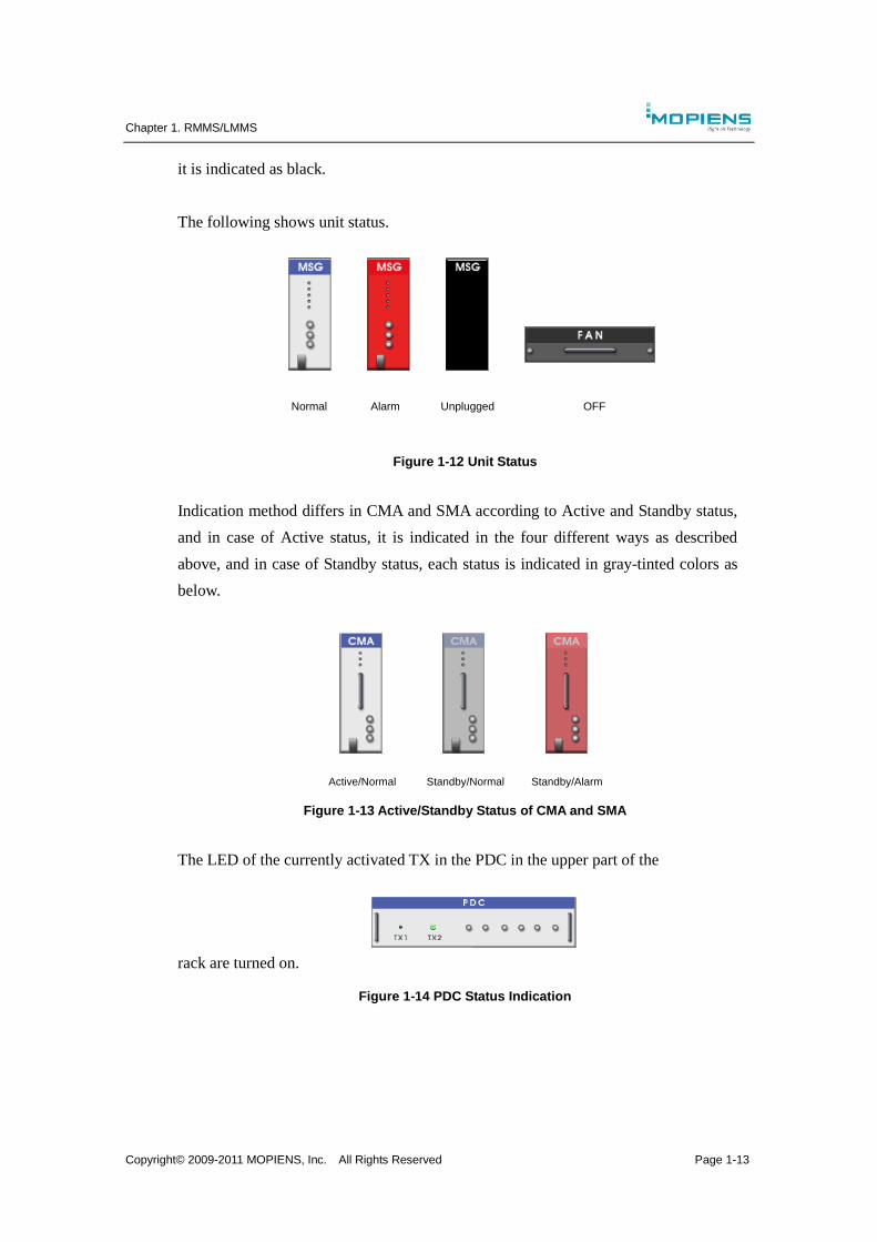
it is indicated as black.
The following shows unit status.
Figure 1-12 Unit Status
Indication method differs in CMA and SMA according to Active and Standby status,
and in case of Active status, it is indicated in the four different ways as described
above, and in case of Standby status, each status is indicated in gray-tinted colors as
below.
Figure 1-13 Active/Standby Status of CMA and SMA
The LED of the currently activated TX in the PDC in the upper part of the
rack are turned on.
Figure 1-14 PDC Status Indication
Normal Alarm Unplugged OFF
Active/Normal Standby/Normal Standby/Alarm
Chapter 1. RMMS/LMMS
Copyright© 2009-2011 MOPIENS, Inc. All Rights Reserved Page 1-14
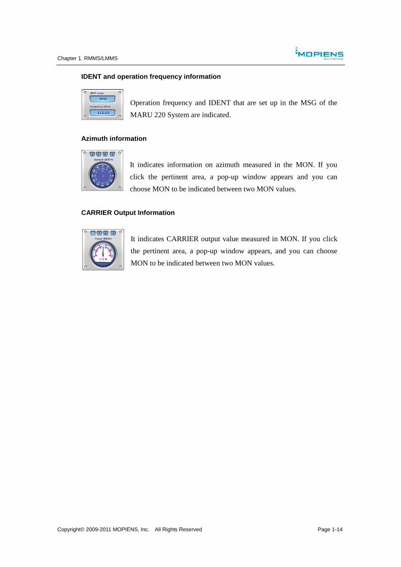
IDENT and operation frequency information
Operation frequency and IDENT that are set up in the MSG of the
MARU 220 System are indicated.
Azimuth information
It indicates information on azimuth measured in the MON. If you
click the pertinent area, a pop-up window appears and you can
choose MON to be indicated between two MON values.
CARRIER Output Information
It indicates CARRIER output value measured in MON. If you click
the pertinent area, a pop-up window appears, and you can choose
MON to be indicated between two MON values.
Chapter 1. RMMS/LMMS
Copyright© 2009-2011 MOPIENS, Inc. All Rights Reserved Page 1-15
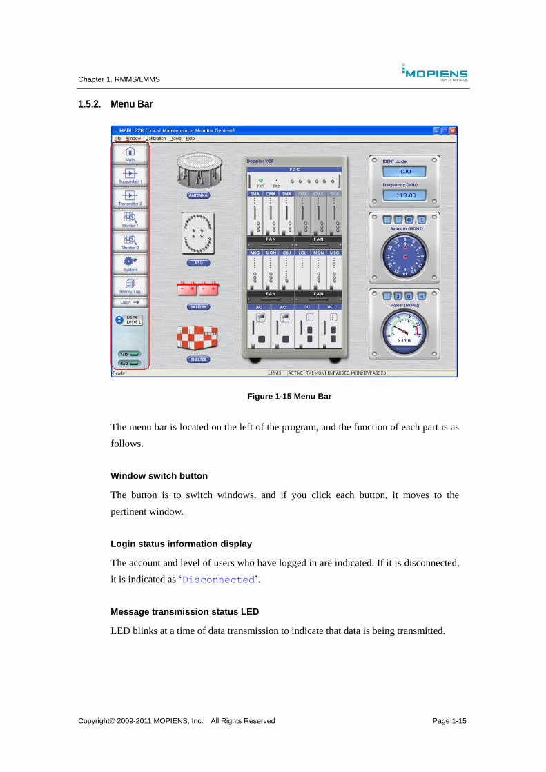
1.5.2. Menu Bar
Figure 1-15 Menu Bar
The menu bar is located on the left of the program, and the function of each part is as
follows.
Window switch button
The button is to switch windows, and if you click each button, it moves to the
pertinent window.
Login status information display
The account and level of users who have logged in are indicated. If it is disconnected,
it is indicated as ‘Disconnected’.
Message transmission status LED
LED blinks at a time of data transmission to indicate that data is being transmitted.
Chapter 1. RMMS/LMMS
Copyright© 2009-2011 MOPIENS, Inc. All Rights Reserved Page 1-16
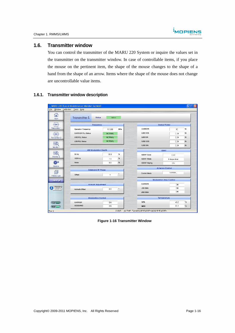
1.6. Transmitter window
You can control the transmitter of the MARU 220 System or inquire the values set in
the transmitter on the transmitter window. In case of controllable items, if you place
the mouse on the pertinent item, the shape of the mouse changes to the shape of a
hand from the shape of an arrow. Items where the shape of the mouse does not change
are uncontrollable value items.
1.6.1. Transmitter window description
Figure 1-16 Transmitter Window
Chapter 1. RMMS/LMMS
Copyright© 2009-2011 MOPIENS, Inc. All Rights Reserved Page 1-17
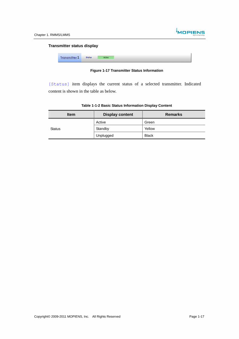
Transmitter status display
Figure 1-17 Transmitter Status Information
[Status] item displays the current status of a selected transmitter. Indicated
content is shown in the table as below.
Table 1-1-2 Basic Status Information Display Content
Item Display content Remarks
Status
Active Green
Standby Yellow
Unplugged Black

Chapter 1. RMMS/LMMS
Copyright© 2009-2011 MOPIENS, Inc. All Rights Reserved Page 1-18
Frequency
Figure 1-18 Frequency Status Display
The frequency item displays the status of the currently set operation frequency, carrier,
USB and LSB PLL.
Table 1-1-3 Frequency Display Content
Item Display content Remarks
Operating Frequency 108.00 ~ 118.00 MHz
CAR PLL Status Normal Green
FAIL Red
USB PLL Status Normal Green
FAIL Red
LSB PLL Status Normal Green
FAIL Red
Chapter 1. RMMS/LMMS
Copyright© 2009-2011 MOPIENS, Inc. All Rights Reserved Page 1-19
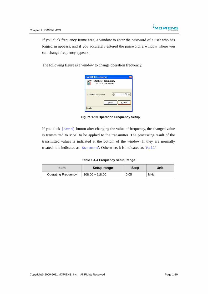
If you click frequency frame area, a window to enter the password of a user who has
logged in appears, and if you accurately entered the password, a window where you
can change frequency appears.
The following figure is a window to change operation frequency.
Figure 1-19 Operation Frequency Setup
If you click [Send] button after changing the value of frequency, the changed value
is transmitted to MSG to be applied to the transmitter. The processing result of the
transmitted values is indicated at the bottom of the window. If they are normally
treated, it is indicated as ‘Success’. Otherwise, it is indicated as ‘Fail’.
Table 1-1-4 Frequency Setup Range
Item Setup range Step Unit
Operating Frequency 108.00 ~ 118.00 0.05 MHz
Chapter 1. RMMS/LMMS
Copyright© 2009-2011 MOPIENS, Inc. All Rights Reserved Page 1-20
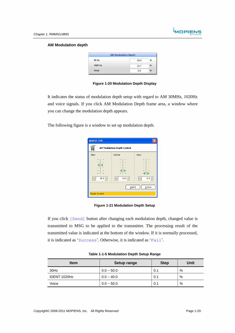
AM Modulation depth
Figure 1-20 Modulation Depth Display
It indicates the status of modulation depth setup with regard to AM 30MHz, 1020Hz
and voice signals. If you click AM Modulation Depth frame area, a window where
you can change the modulation depth appears.
The following figure is a window to set up modulation depth.
Figure 1-21 Modulation Depth Setup
If you click [Send] button after changing each modulation depth, changed value is
transmitted to MSG to be applied to the transmitter. The processing result of the
transmitted value is indicated at the bottom of the window. If it is normally processed,
it is indicated as ‘Success’. Otherwise, it is indicated as ‘Fail’.
Table 1-1-5 Modulation Depth Setup Range
Item Setup range Step Unit
30Hz 0.0 ~ 50.0 0.1 %
IDENT 1020Hz 0.0 ~ 40.0 0.1 %
Voice 0.0 ~ 50.0 0.1 %
Chapter 1. RMMS/LMMS
Copyright© 2009-2011 MOPIENS, Inc. All Rights Reserved Page 1-21
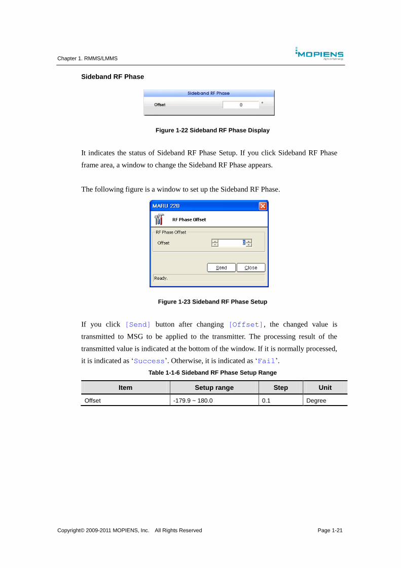
Sideband RF Phase
Figure 1-22 Sideband RF Phase Display
It indicates the status of Sideband RF Phase Setup. If you click Sideband RF Phase
frame area, a window to change the Sideband RF Phase appears.
The following figure is a window to set up the Sideband RF Phase.
Figure 1-23 Sideband RF Phase Setup
If you click [Send] button after changing [Offset], the changed value is
transmitted to MSG to be applied to the transmitter. The processing result of the
transmitted value is indicated at the bottom of the window. If it is normally processed,
it is indicated as ‘Success’. Otherwise, it is indicated as ‘Fail’.
Table 1-1-6 Sideband RF Phase Setup Range
Item Setup range Step Unit
Offset -179.9 ~ 180.0 0.1 Degree
Chapter 1. RMMS/LMMS
Copyright© 2009-2011 MOPIENS, Inc. All Rights Reserved Page 1-22
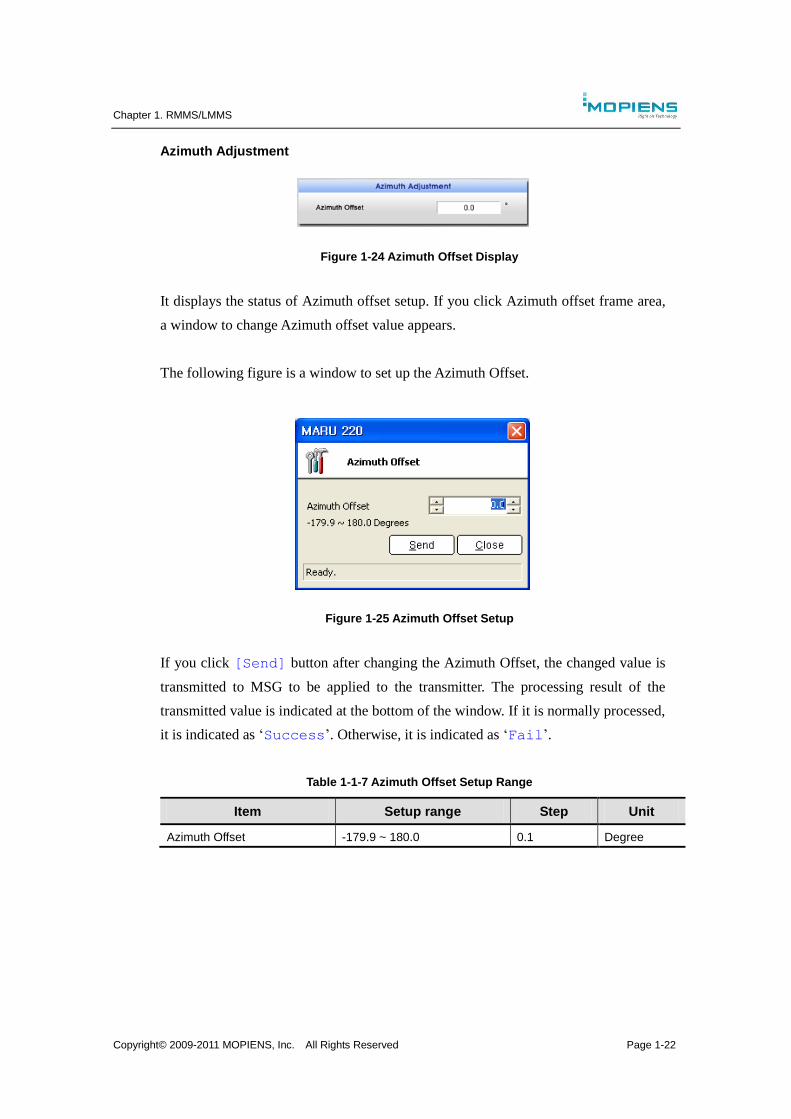
Azimuth Adjustment
Figure 1-24 Azimuth Offset Display
It displays the status of Azimuth offset setup. If you click Azimuth offset frame area,
a window to change Azimuth offset value appears.
The following figure is a window to set up the Azimuth Offset.
Figure 1-25 Azimuth Offset Setup
If you click [Send] button after changing the Azimuth Offset, the changed value is
transmitted to MSG to be applied to the transmitter. The processing result of the
transmitted value is indicated at the bottom of the window. If it is normally processed,
it is indicated as ‘Success’. Otherwise, it is indicated as ‘Fail’.
Table 1-1-7 Azimuth Offset Setup Range
Item Setup range Step Unit
Azimuth Offset -179.9 ~ 180.0 0.1 Degree
Chapter 1. RMMS/LMMS
Copyright© 2009-2011 MOPIENS, Inc. All Rights Reserved Page 1-23
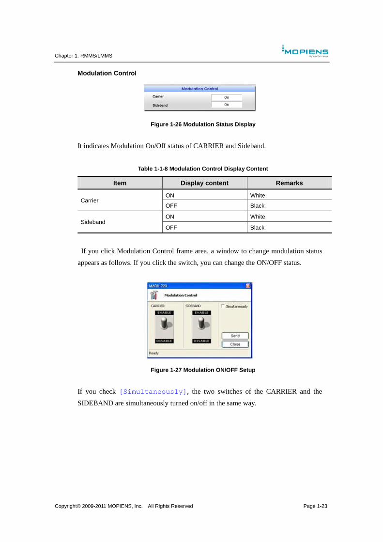
Modulation Control
Figure 1-26 Modulation Status Display
It indicates Modulation On/Off status of CARRIER and Sideband.
Table 1-1-8 Modulation Control Display Content
Item Display content Remarks
Carrier ON White
OFF Black
Sideband ON White
OFF Black
If you click Modulation Control frame area, a window to change modulation status
appears as follows. If you click the switch, you can change the ON/OFF status.
Figure 1-27 Modulation ON/OFF Setup
If you check [Simultaneously], the two switches of the CARRIER and the
SIDEBAND are simultaneously turned on/off in the same way.
Chapter 1. RMMS/LMMS
Copyright© 2009-2011 MOPIENS, Inc. All Rights Reserved Page 1-24
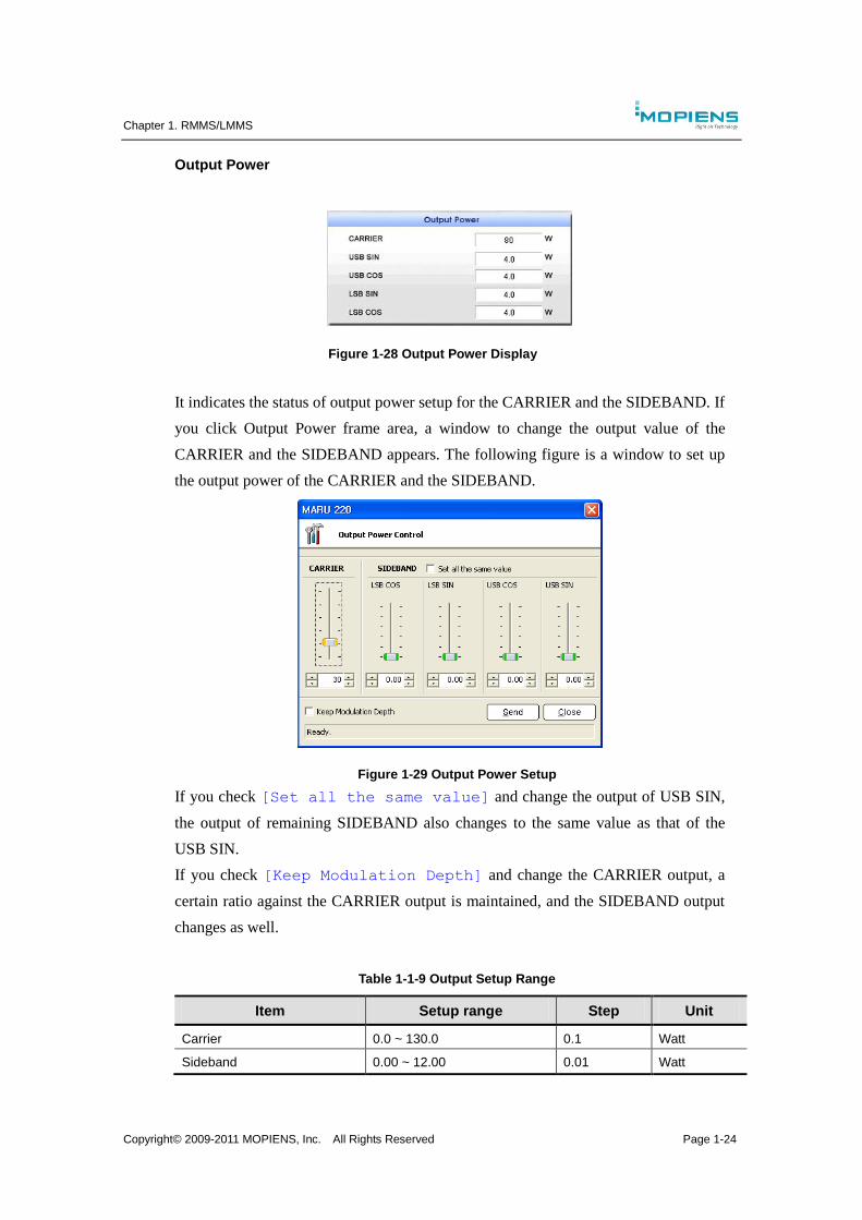
Output Power
Figure 1-28 Output Power Display
It indicates the status of output power setup for the CARRIER and the SIDEBAND. If
you click Output Power frame area, a window to change the output value of the
CARRIER and the SIDEBAND appears. The following figure is a window to set up
the output power of the CARRIER and the SIDEBAND.
Figure 1-29 Output Power Setup
If you check [Set all the same value] and change the output of USB SIN,
the output of remaining SIDEBAND also changes to the same value as that of the
USB SIN.
If you check [Keep Modulation Depth] and change the CARRIER output, a
certain ratio against the CARRIER output is maintained, and the SIDEBAND output
changes as well.
Table 1-1-9 Output Setup Range
Item Setup range Step Unit
Carrier 0.0 ~ 130.0 0.1 Watt
Sideband 0.00 ~ 12.00 0.01 Watt
Chapter 1. RMMS/LMMS
Copyright© 2009-2011 MOPIENS, Inc. All Rights Reserved Page 1-25
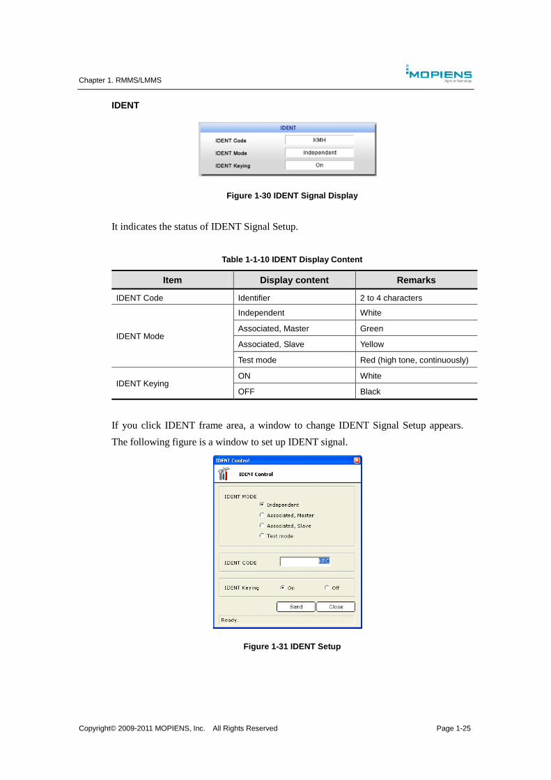
IDENT
Figure 1-30 IDENT Signal Display
It indicates the status of IDENT Signal Setup.
Table 1-1-10 IDENT Display Content
Item Display content Remarks
IDENT Code Identifier 2 to 4 characters
IDENT Mode
Independent White
Associated, Master Green
Associated, Slave Yellow
Test mode Red (high tone, continuously)
IDENT Keying ON White
OFF Black
If you click IDENT frame area, a window to change IDENT Signal Setup appears.
The following figure is a window to set up IDENT signal.
Figure 1-31 IDENT Setup
Chapter 1. RMMS/LMMS
Copyright© 2009-2011 MOPIENS, Inc. All Rights Reserved Page 1-26
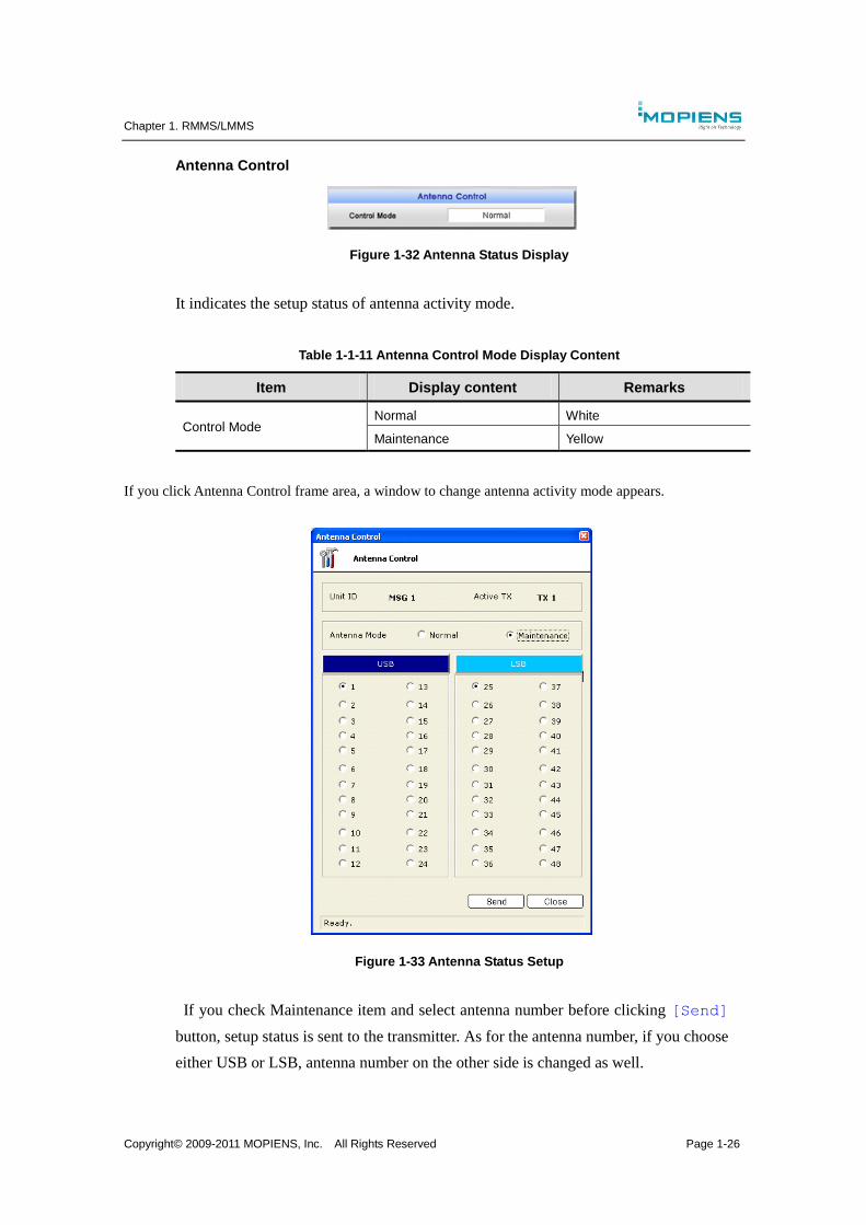
Antenna Control
Figure 1-32 Antenna Status Display
It indicates the setup status of antenna activity mode.
Table 1-1-11 Antenna Control Mode Display Content
Item Display content Remarks
Control Mode Normal White
Maintenance Yellow
If you click Antenna Control frame area, a window to change antenna activity mode appears.
Figure 1-33 Antenna Status Setup
If you check Maintenance item and select antenna number before clicking [Send]
button, setup status is sent to the transmitter. As for the antenna number, if you choose
either USB or LSB, antenna number on the other side is changed as well.
Chapter 1. RMMS/LMMS
Copyright© 2009-2011 MOPIENS, Inc. All Rights Reserved Page 1-27
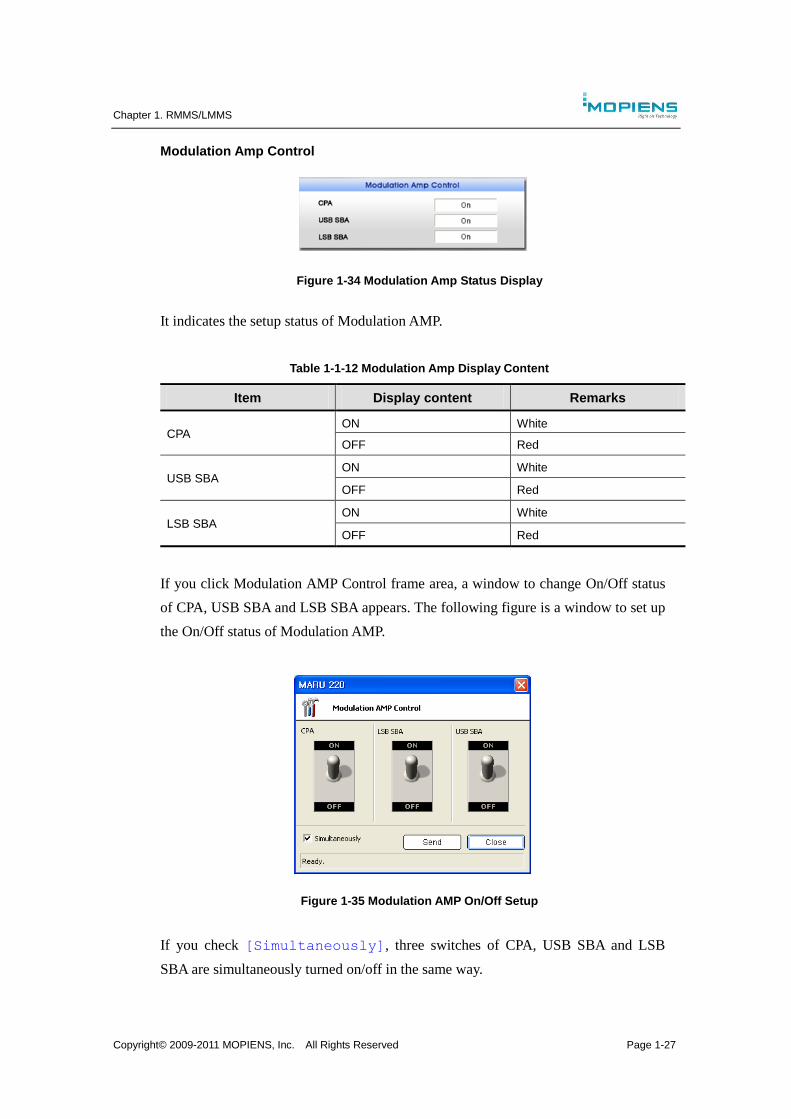
Modulation Amp Control
Figure 1-34 Modulation Amp Status Display
It indicates the setup status of Modulation AMP.
Table 1-1-12 Modulation Amp Display Content
Item Display content Remarks
CPA ON White
OFF Red
USB SBA ON White
OFF Red
LSB SBA ON White
OFF Red
If you click Modulation AMP Control frame area, a window to change On/Off status
of CPA, USB SBA and LSB SBA appears. The following figure is a window to set up
the On/Off status of Modulation AMP.
Figure 1-35 Modulation AMP On/Off Setup
If you check [Simultaneously], three switches of CPA, USB SBA and LSB
SBA are simultaneously turned on/off in the same way.
Chapter 1. RMMS/LMMS
Copyright© 2009-2011 MOPIENS, Inc. All Rights Reserved Page 1-28
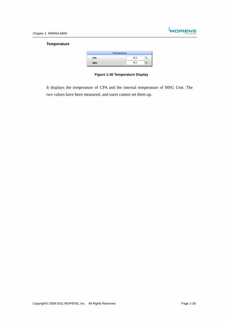
Temperature
Figure 1-36 Temperature Display
It displays the temperature of CPA and the internal temperature of MSG Unit. The
two values have been measured, and users cannot set them up.
Chapter 1. RMMS/LMMS
Copyright© 2009-2011 MOPIENS, Inc. All Rights Reserved Page 1-29
1.6.2. Transmitter menu
If you click the right button of the mouse on the transmitter window, the following
menu item appears.
Refresh
It transmits MSG status reference message to LCU and then renew the transmitter
window.
Write to EEPROM
It saves the values currently set in the transmitter in the pertinent MSG EEPROM.
Print…
It prints the values currently set in the transmitter.
Chapter 1. RMMS/LMMS
Copyright© 2009-2011 MOPIENS, Inc. All Rights Reserved Page 1-30
1.7. Monitor window
1.7.1. Main monitor window description
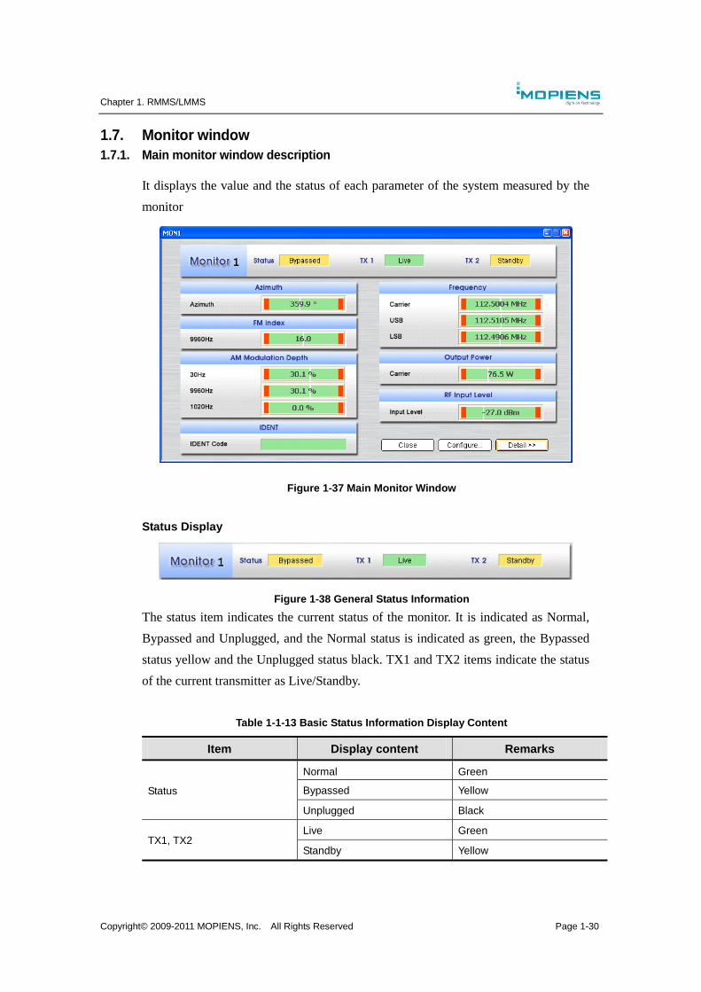
It displays the value and the status of each parameter of the system measured by the
monitor
Figure 1-37 Main Monitor Window
Status Display
Figure 1-38 General Status Information
The status item indicates the current status of the monitor. It is indicated as Normal,
Bypassed and Unplugged, and the Normal status is indicated as green, the Bypassed
status yellow and the Unplugged status black. TX1 and TX2 items indicate the status
of the current transmitter as Live/Standby.
Table 1-1-13 Basic Status Information Display Content
Item Display content Remarks
Status
Normal Green
Bypassed Yellow
Unplugged Black
TX1, TX2 Live Green
Standby Yellow
Chapter 1. RMMS/LMMS
Copyright© 2009-2011 MOPIENS, Inc. All Rights Reserved Page 1-31
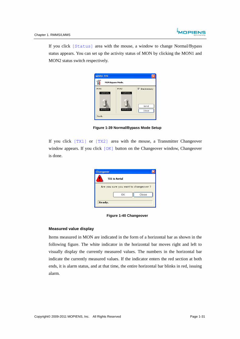
If you click [Status] area with the mouse, a window to change Normal/Bypass
status appears. You can set up the activity status of MON by clicking the MON1 and
MON2 status switch respectively.
Figure 1-39 Normal/Bypass Mode Setup
If you click [TX1] or [TX2] area with the mouse, a Transmitter Changeover
window appears. If you click [OK] button on the Changeover window, Changeover
is done.
Figure 1-40 Changeover
Measured value display
Items measured in MON are indicated in the form of a horizontal bar as shown in the
following figure. The white indicator in the horizontal bar moves right and left to
visually display the currently measured values. The numbers in the horizontal bar
indicate the currently measured values. If the indicator enters the red section at both
ends, it is alarm status, and at that time, the entire horizontal bar blinks in red, issuing
alarm.
Chapter 1. RMMS/LMMS
Copyright© 2009-2011 MOPIENS, Inc. All Rights Reserved Page 1-32
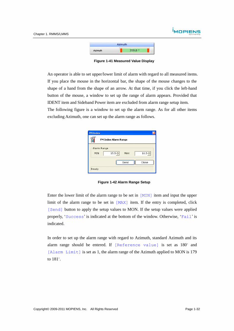
Figure 1-41 Measured Value Display
An operator is able to set upper/lower limit of alarm with regard to all measured items.
If you place the mouse in the horizontal bar, the shape of the mouse changes to the
shape of a hand from the shape of an arrow. At that time, if you click the left-hand
button of the mouse, a window to set up the range of alarm appears. Provided that
IDENT item and Sideband Power item are excluded from alarm range setup item.
The following figure is a window to set up the alarm range. As for all other items
excluding Azimuth, one can set up the alarm range as follows.
Figure 1-42 Alarm Range Setup
Enter the lower limit of the alarm range to be set in [MIN] item and input the upper
limit of the alarm range to be set in [MAX] item. If the entry is completed, click
[Send] button to apply the setup values to MON. If the setup values were applied
properly, ‘Success’ is indicated at the bottom of the window. Otherwise, ‘Fail’ is
indicated.
In order to set up the alarm range with regard to Azimuth, standard Azimuth and its
alarm range should be entered. If [Reference value] is set as 180˚ and
[Alarm Limit] is set as 1, the alarm range of the Azimuth applied to MON is 179
to 181˚.
Chapter 1. RMMS/LMMS
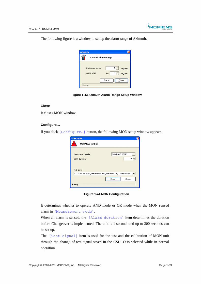
Copyright© 2009-2011 MOPIENS, Inc. All Rights Reserved Page 1-33
The following figure is a window to set up the alarm range of Azimuth.
Figure 1-43 Azimuth Alarm Range Setup Window
Close
It closes MON window.
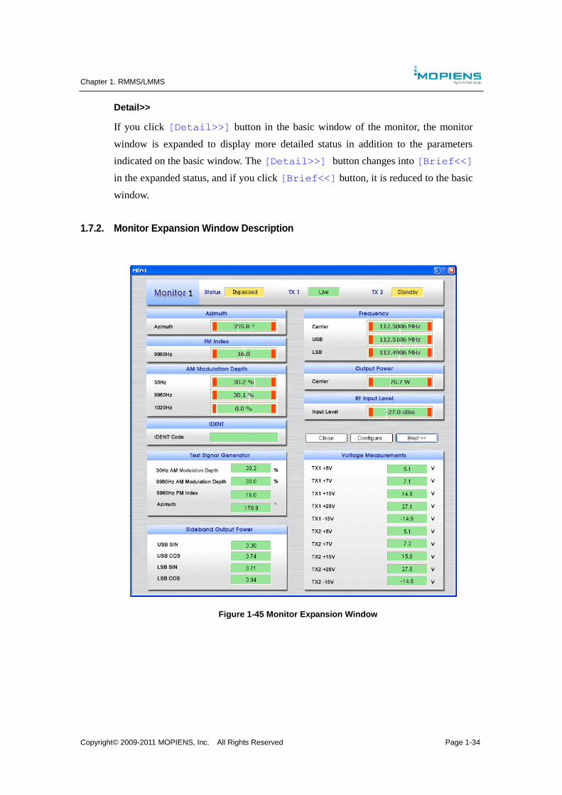
Configure…
If you click [Configure…] button, the following MON setup window appears.
Figure 1-44 MON Configuration
It determines whether to operate AND mode or OR mode when the MON sensed
alarm in [Measurement mode].
When an alarm is sensed, the [Alarm duration] item determines the duration
before Changeover is implemented. The unit is 1 second, and up to 300 seconds can
be set up.
The [Test signal] item is used for the test and the calibration of MON unit
through the change of test signal saved in the CSU. O is selected while in normal
operation.
Chapter 1. RMMS/LMMS
Copyright© 2009-2011 MOPIENS, Inc. All Rights Reserved Page 1-34
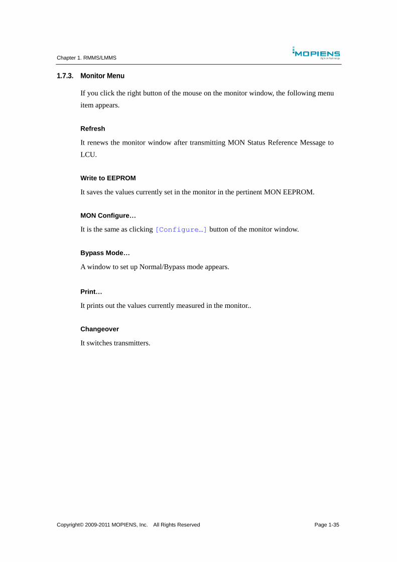
Detail>>
If you click [Detail>>] button in the basic window of the monitor, the monitor
window is expanded to display more detailed status in addition to the parameters
indicated on the basic window. The [Detail>>] button changes into [Brief<<]
in the expanded status, and if you click [Brief<<] button, it is reduced to the basic
window.
1.7.2. Monitor Expansion Window Description
Figure 1-45 Monitor Expansion Window
Chapter 1. RMMS/LMMS
Copyright© 2009-2011 MOPIENS, Inc. All Rights Reserved Page 1-35
1.7.3. Monitor Menu
If you click the right button of the mouse on the monitor window, the following menu
item appears.
Refresh
It renews the monitor window after transmitting MON Status Reference Message to
LCU.
Write to EEPROM
It saves the values currently set in the monitor in the pertinent MON EEPROM.
MON Configure…
It is the same as clicking [Configure…] button of the monitor window.
Bypass Mode…
A window to set up Normal/Bypass mode appears.
Print…
It prints out the values currently measured in the monitor..
Changeover
It switches transmitters.
Chapter 1. RMMS/LMMS
Copyright© 2009-2011 MOPIENS, Inc. All Rights Reserved Page 1-36
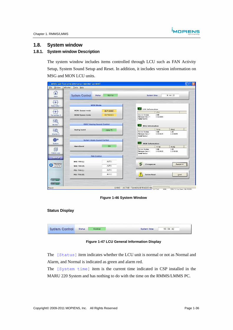
1.8. System window
1.8.1. System window Description
The system window includes items controlled through LCU such as FAN Activity
Setup, System Sound Setup and Reset. In addition, it includes version information on
MSG and MON LCU units.
Figure 1-46 System Window
Status Display
Figure 1-47 LCU General Information Display
The [Status] item indicates whether the LCU unit is normal or not as Normal and
Alarm, and Normal is indicated as green and alarm red.
The [System time] item is the current time indicated in CSP installed in the
MARU 220 System and has nothing to do with the time on the RMMS/LMMS PC.
Chapter 1. RMMS/LMMS
Copyright© 2009-2011 MOPIENS, Inc. All Rights Reserved Page 1-37
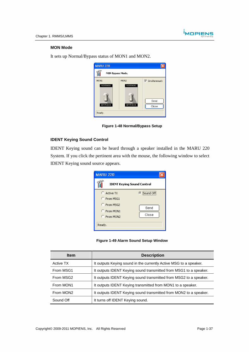
MON Mode
It sets up Normal/Bypass status of MON1 and MON2.
Figure 1-48 Normal/Bypass Setup
IDENT Keying Sound Control
IDENT Keying sound can be heard through a speaker installed in the MARU 220
System. If you click the pertinent area with the mouse, the following window to select
IDENT Keying sound source appears.
Figure 1-49 Alarm Sound Setup Window
Item Description
Active TX It outputs Keying sound in the currently Active MSG to a speaker.
From MSG1 It outputs IDENT Keying sound transmitted from MSG1 to a speaker.
From MSG2 It outputs IDENT Keying sound transmitted from MSG2 to a speaker.
From MON1 It outputs IDENT Keying transmitted from MON1 to a speaker.
From MON2 It outputs IDENT Keying sound transmitted from MON2 to a speaker.
Sound Off It turns off IDENT Keying sound.
Chapter 1. RMMS/LMMS
Copyright© 2009-2011 MOPIENS, Inc. All Rights Reserved Page 1-38
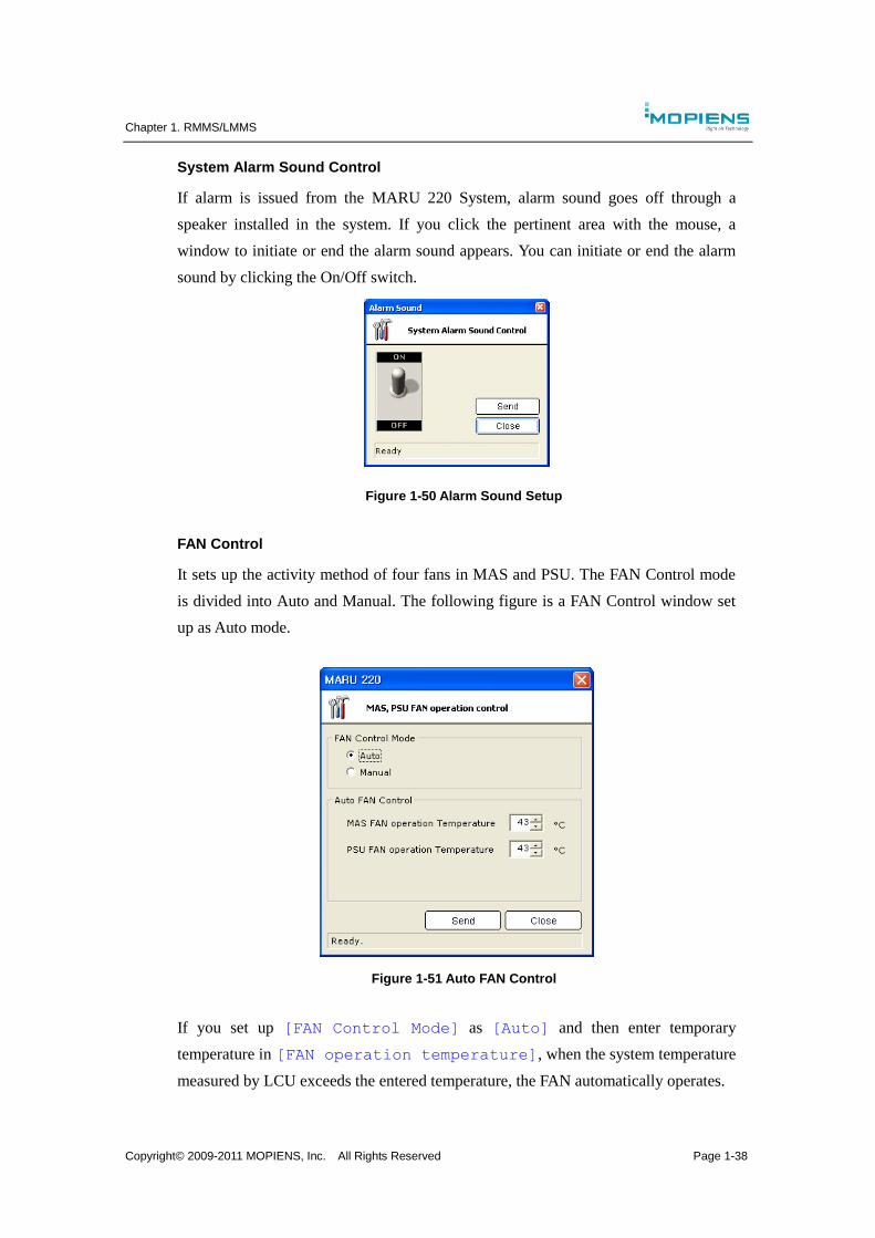
System Alarm Sound Control
If alarm is issued from the MARU 220 System, alarm sound goes off through a
speaker installed in the system. If you click the pertinent area with the mouse, a
window to initiate or end the alarm sound appears. You can initiate or end the alarm
sound by clicking the On/Off switch.
Figure 1-50 Alarm Sound Setup
FAN Control
It sets up the activity method of four fans in MAS and PSU. The FAN Control mode
is divided into Auto and Manual. The following figure is a FAN Control window set
up as Auto mode.
Figure 1-51 Auto FAN Control
If you set up [FAN Control Mode] as [Auto] and then enter temporary
temperature in [FAN operation temperature], when the system temperature
measured by LCU exceeds the entered temperature, the FAN automatically operates.
Chapter 1. RMMS/LMMS
Copyright© 2009-2011 MOPIENS, Inc. All Rights Reserved Page 1-39
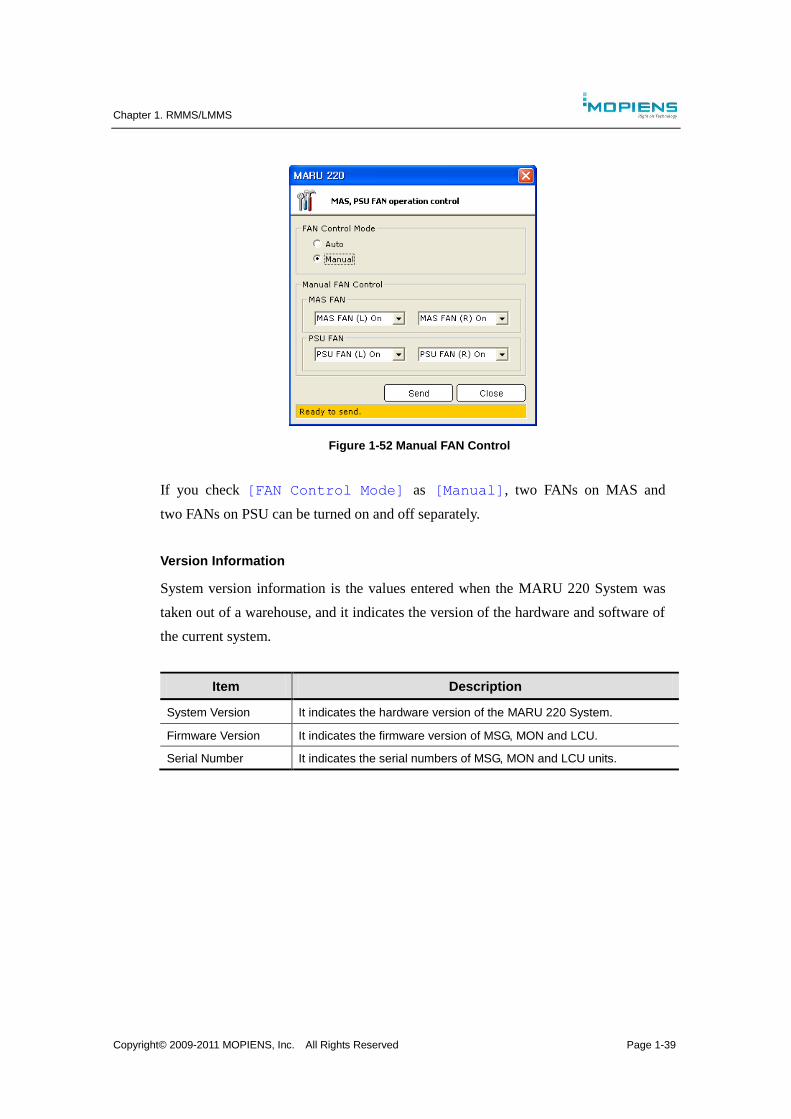
Figure 1-52 Manual FAN Control
If you check [FAN Control Mode] as [Manual], two FANs on MAS and
two FANs on PSU can be turned on and off separately.
Version Information
System version information is the values entered when the MARU 220 System was
taken out of a warehouse, and it indicates the version of the hardware and software of
the current system.
Item Description
System Version It indicates the hardware version of the MARU 220 System.
Firmware Version It indicates the firmware version of MSG, MON and LCU.
Serial Number It indicates the serial numbers of MSG, MON and LCU units.
Chapter 1. RMMS/LMMS
Copyright© 2009-2011 MOPIENS, Inc. All Rights Reserved Page 1-40
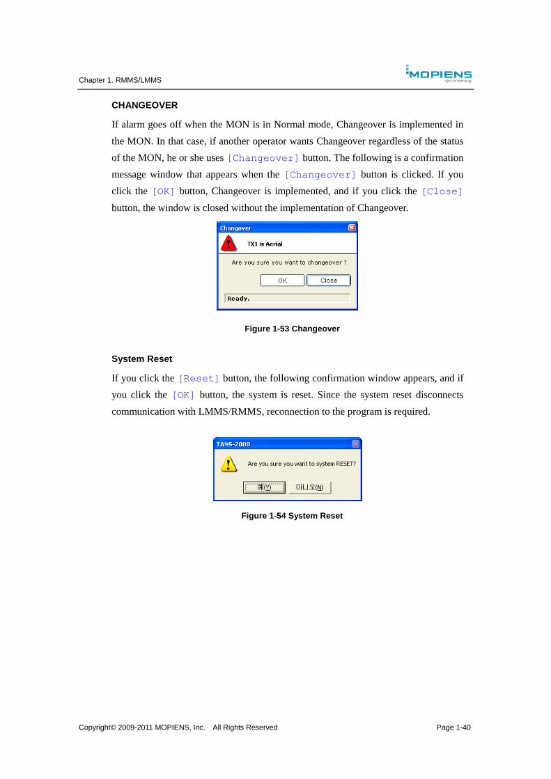
CHANGEOVER
If alarm goes off when the MON is in Normal mode, Changeover is implemented in
the MON. In that case, if another operator wants Changeover regardless of the status
of the MON, he or she uses [Changeover] button. The following is a confirmation
message window that appears when the [Changeover] button is clicked. If you
click the [OK] button, Changeover is implemented, and if you click the [Close]
button, the window is closed without the implementation of Changeover.
Figure 1-53 Changeover
System Reset
If you click the [Reset] button, the following confirmation window appears, and if
you click the [OK] button, the system is reset. Since the system reset disconnects
communication with LMMS/RMMS, reconnection to the program is required.
Figure 1-54 System Reset
Chapter 1. RMMS/LMMS
Copyright© 2009-2011 MOPIENS, Inc. All Rights Reserved Page 1-41
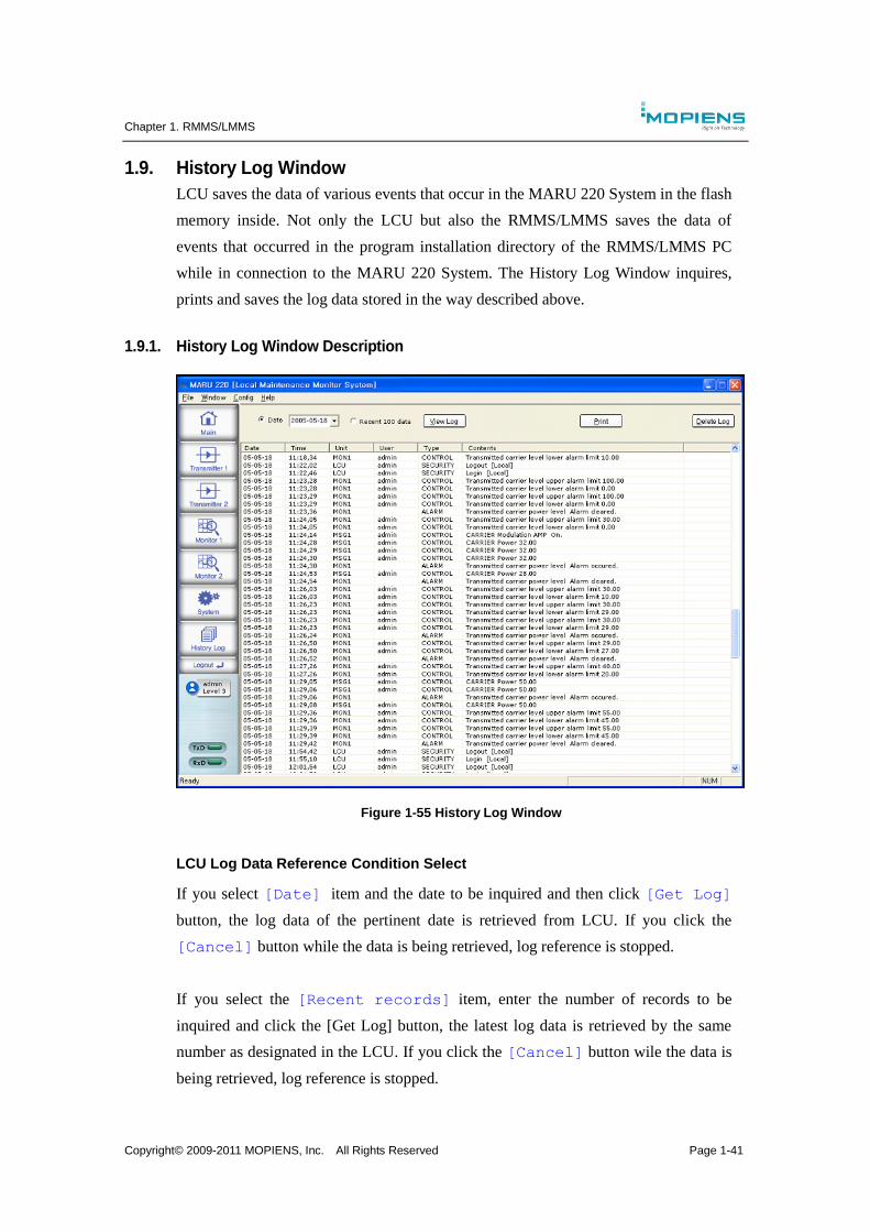
1.9. History Log Window
LCU saves the data of various events that occur in the MARU 220 System in the flash
memory inside. Not only the LCU but also the RMMS/LMMS saves the data of
events that occurred in the program installation directory of the RMMS/LMMS PC
while in connection to the MARU 220 System. The History Log Window inquires,
prints and saves the log data stored in the way described above.
1.9.1. History Log Window Description
Figure 1-55 History Log Window
LCU Log Data Reference Condition Select
If you select [Date] item and the date to be inquired and then click [Get Log]
button, the log data of the pertinent date is retrieved from LCU. If you click the
[Cancel] button while the data is being retrieved, log reference is stopped.
If you select the [Recent records] item, enter the number of records to be
inquired and click the [Get Log] button, the latest log data is retrieved by the same
number as designated in the LCU. If you click the [Cancel] button wile the data is
being retrieved, log reference is stopped.
Chapter 1. RMMS/LMMS
Copyright© 2009-2011 MOPIENS, Inc. All Rights Reserved Page 1-42
Save as…
It saves History Log Content indicated on the window in the RMMS/LMMS PC as a
file. The saved file can be checked through the use of a compiler such as ‘Notepad’
and [Load…] button.
Load…
It indicates the content of the History Log file saved in the RMMS/LMMS PC on the
window.
Print…
It prints the content of the History Log displayed on the window.
Information
It displays the status of progress when the log data is retrieved from LCU. [Total
xx records] indicates the number of entire data and [Received xx
records] indicates the number of data that have been read until now.
Log Data Indication
No: It indicates the number of data.
Date: The date when an event occurred is indicated.
Time: The time when an event occurred is indicated.
Unit: The name of the unit where an event occurred is indicated.
User: In case of control record, a user who logged in the RMMS/LMMS is
indicated. In case of alarm record, it is indicated as a blank space.
Type: Alarm Occur/Release record is indicated as Alarm, and Control record is
indicated as Control.
Description: The content of an event that occurred is indicated.
Chapter 1. RMMS/LMMS
Copyright© 2009-2011 MOPIENS, Inc. All Rights Reserved Page 1-43
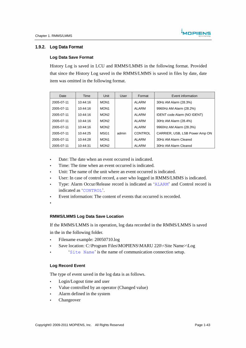
1.9.2. Log Data Format
Log Data Save Format
History Log is saved in LCU and RMMS/LMMS in the following format. Provided
that since the History Log saved in the RMMS/LMMS is saved in files by date, date
item was omitted in the following format.
Date Time Unit User Format Event information
2005-07-11
2005-07-11
2005-07-11
2005-07-11
2005-07-11
2005-07-11
2005-07-11
2005-07-11
10:44:16
10:44:16
10:44:16
10:44:16
10:44:16
10:44:25
10:44:28
10:44:31
MON1
MON1
MON2
MON2
MON2
MSG1
MON1
MON2
admin
ALARM
ALARM
ALARM
ALARM
ALARM
CONTROL
ALARM
ALARM
30Hz AM Alarm (28.3%)
9960Hz AM Alarm (28.2%)
IDENT code Alarm (NO IDENT)
30Hz AM Alarm (28.4%)
9960Hz AM Alarm (28.3%)
CARRIER, USB, LSB Power Amp ON
30Hz AM Alarm Cleared
30Hz AM Alarm Cleared
Date: The date when an event occurred is indicated.
Time: The time when an event occurred is indicated.
Unit: The name of the unit where an event occurred is indicated.
User: In case of control record, a user who logged in RMMS/LMMS is indicated.
Type: Alarm Occur/Release record is indicated as ‘ALARM’ and Control record is
indicated as ‘CONTROL’.
Event information: The content of events that occurred is recorded.
RMMS/LMMS Log Data Save Location
If the RMMS/LMMS is in operation, log data recorded in the RMMS/LMMS is saved
in the in the following folder.
Filename example: 20050710.log
Save location: C:\Program Files\MOPIENS\MARU 220\<Site Name>\Log
‘Site Name’ is the name of communication connection setup.
Log Record Event
The type of event saved in the log data is as follows.
Login/Logout time and user
Value controlled by an operator (Changed value)
Alarm defined in the system
Changeover
Chapter 1. RMMS/LMMS
Copyright© 2009-2011 MOPIENS, Inc. All Rights Reserved Page 1-44
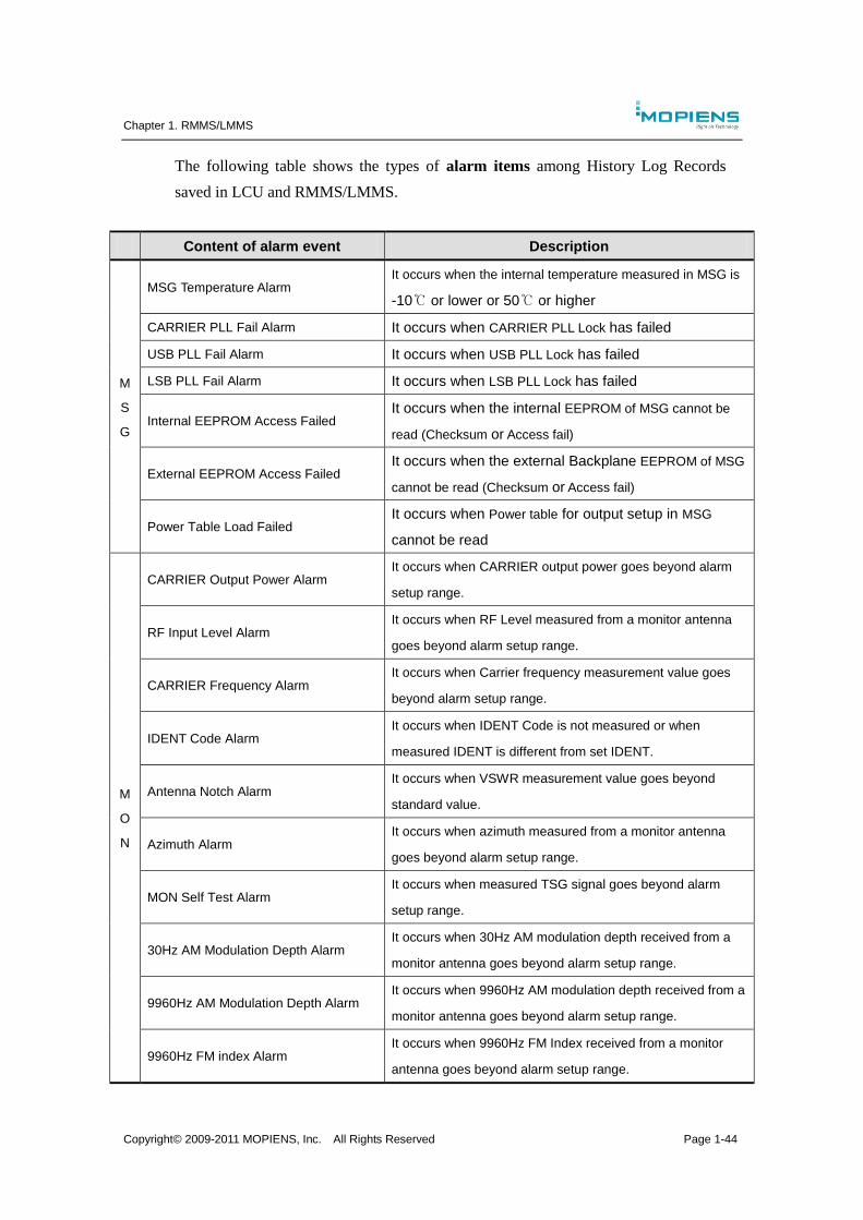
The following table shows the types of alarm items among History Log Records
saved in LCU and RMMS/LMMS.
Content of alarm event Description
M
S
G
MSG Temperature Alarm It occurs when the internal temperature measured in MSG is
-10℃ or lower or 50℃ or higher
CARRIER PLL Fail Alarm It occurs when CARRIER PLL Lock has failed
USB PLL Fail Alarm It occurs when USB PLL Lock has failed
LSB PLL Fail Alarm It occurs when LSB PLL Lock has failed
Internal EEPROM Access Failed It occurs when the internal EEPROM of MSG cannot be
read (Checksum or Access fail)
External EEPROM Access Failed It occurs when the external Backplane EEPROM of MSG
cannot be read (Checksum or Access fail)
Power Table Load Failed It occurs when Power table for output setup in MSG
cannot be read
M
O
N
CARRIER Output Power Alarm It occurs when CARRIER output power goes beyond alarm
setup range.
RF Input Level Alarm It occurs when RF Level measured from a monitor antenna
goes beyond alarm setup range.
CARRIER Frequency Alarm It occurs when Carrier frequency measurement value goes
beyond alarm setup range.
IDENT Code Alarm It occurs when IDENT Code is not measured or when
measured IDENT is different from set IDENT.
Antenna Notch Alarm It occurs when VSWR measurement value goes beyond
standard value.
Azimuth Alarm It occurs when azimuth measured from a monitor antenna
goes beyond alarm setup range.
MON Self Test Alarm It occurs when measured TSG signal goes beyond alarm
setup range.
30Hz AM Modulation Depth Alarm It occurs when 30Hz AM modulation depth received from a
monitor antenna goes beyond alarm setup range.
9960Hz AM Modulation Depth Alarm It occurs when 9960Hz AM modulation depth received from a
monitor antenna goes beyond alarm setup range.
9960Hz FM index Alarm It occurs when 9960Hz FM Index received from a monitor
antenna goes beyond alarm setup range.

Chapter 1. RMMS/LMMS
Copyright© 2009-2011 MOPIENS, Inc. All Rights Reserved Page 1-45
Content of alarm event Description
1020Hz AM Modulation Depth Alarm It occurs when 1020Hz AM modulation depth received from a
monitor antenna goes beyond alarm setup range.
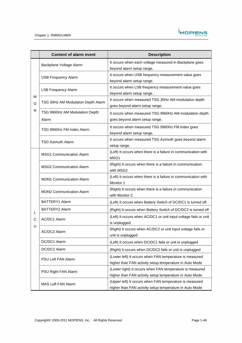
Chapter 1. RMMS/LMMS
Copyright© 2009-2011 MOPIENS, Inc. All Rights Reserved Page 1-46
Content of alarm event Description
M
O
N
Backplane Voltage Alarm It occurs when each voltage measured in Backplane goes
beyond alarm setup range.
USB Frequency Alarm It occurs when USB frequency measurement value goes
beyond alarm setup range.
LSB Frequency Alarm It occurs when LSB frequency measurement value goes
beyond alarm setup range.
TSG 30Hz AM Modulation Depth Alarm It occurs when measured TSG 30Hz AM modulation depth
goes beyond alarm setup range.
TSG 9960Hz AM Modulation Depth
Alarm
It occurs when measured TSG 9960Hz AM modulation depth
goes beyond alarm setup range.
TSG 9960Hz FM Index Alarm It occurs when measured TSG 9960Hz FM Index goes
beyond alarm setup range.
TSG Azimuth Alarm It occurs when measured TSG Azimuth goes beyond alarm
setup range.
L
C
U
MSG1 Communication Alarm (Left) It occurs when there is a failure in communication with
MSG1
MSG2 Communication Alarm (Right) It occurs when there is a failure in communication
with MSG2
MON1 Communication Alarm (Left) It occurs when there is a failure in communication with
Monitor 1
MON2 Communication Alarm (Right) It occurs when there is a failure in communication
with Monitor 2
BATTERY1 Alarm (Left) It occurs when Battery Switch of DC/DC1 is turned off.
BATTERY2 Alarm (Right) It occurs when Battery Switch of DC/DC2 is turned off
AC/DC1 Alarm (Left) It occurs when AC/DC1 or unit input voltage fails or unit
is unplugged
AC/DC2 Alarm (Right) It occurs when AC/DC2 or unit input voltage fails or
unit is unplugged
DC/DC1 Alarm (Left) It occurs when DC/DC1 fails or unit is unplugged
DC/DC2 Alarm (Right) It occurs when DC/DC2 fails or unit is unplugged
PSU Left FAN Alarm (Lower left) It occurs when FAN temperature is measured
higher than FAN activity setup temperature in Auto Mode
PSU Right FAN Alarm (Lower right) It occurs when FAN temperature is measured
higher than FAN activity setup temperature in Auto Mode
MAS Left FAN Alarm (Upper left) It occurs when FAN temperature is measured
higher than FAN activity setup temperature in Auto Mode
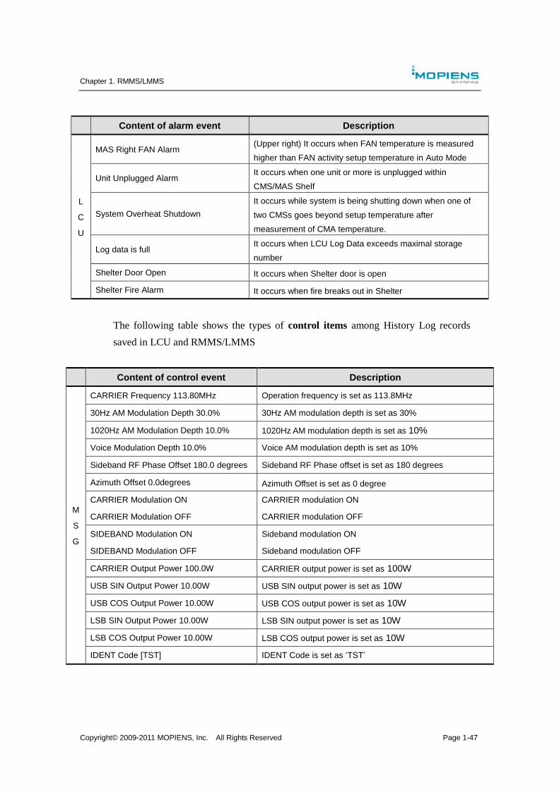
Chapter 1. RMMS/LMMS
Copyright© 2009-2011 MOPIENS, Inc. All Rights Reserved Page 1-47
Content of alarm event Description
L
C
U
MAS Right FAN Alarm (Upper right) It occurs when FAN temperature is measured
higher than FAN activity setup temperature in Auto Mode
Unit Unplugged Alarm It occurs when one unit or more is unplugged within
CMS/MAS Shelf
System Overheat Shutdown
It occurs while system is being shutting down when one of
two CMSs goes beyond setup temperature after
measurement of CMA temperature.
Log data is full It occurs when LCU Log Data exceeds maximal storage
number
Shelter Door Open It occurs when Shelter door is open
Shelter Fire Alarm It occurs when fire breaks out in Shelter
The following table shows the types of control items among History Log records
saved in LCU and RMMS/LMMS
Content of control event Description
M
S
G
CARRIER Frequency 113.80MHz Operation frequency is set as 113.8MHz
30Hz AM Modulation Depth 30.0% 30Hz AM modulation depth is set as 30%
1020Hz AM Modulation Depth 10.0% 1020Hz AM modulation depth is set as 10%
Voice Modulation Depth 10.0% Voice AM modulation depth is set as 10%
Sideband RF Phase Offset 180.0 degrees Sideband RF Phase offset is set as 180 degrees
Azimuth Offset 0.0degrees Azimuth Offset is set as 0 degree
CARRIER Modulation ON
CARRIER Modulation OFF
CARRIER modulation ON
CARRIER modulation OFF
SIDEBAND Modulation ON
SIDEBAND Modulation OFF
Sideband modulation ON
Sideband modulation OFF
CARRIER Output Power 100.0W CARRIER output power is set as 100W
USB SIN Output Power 10.00W USB SIN output power is set as 10W
USB COS Output Power 10.00W USB COS output power is set as 10W
LSB SIN Output Power 10.00W LSB SIN output power is set as 10W
LSB COS Output Power 10.00W LSB COS output power is set as 10W
IDENT Code [TST] IDENT Code is set as ‘TST’
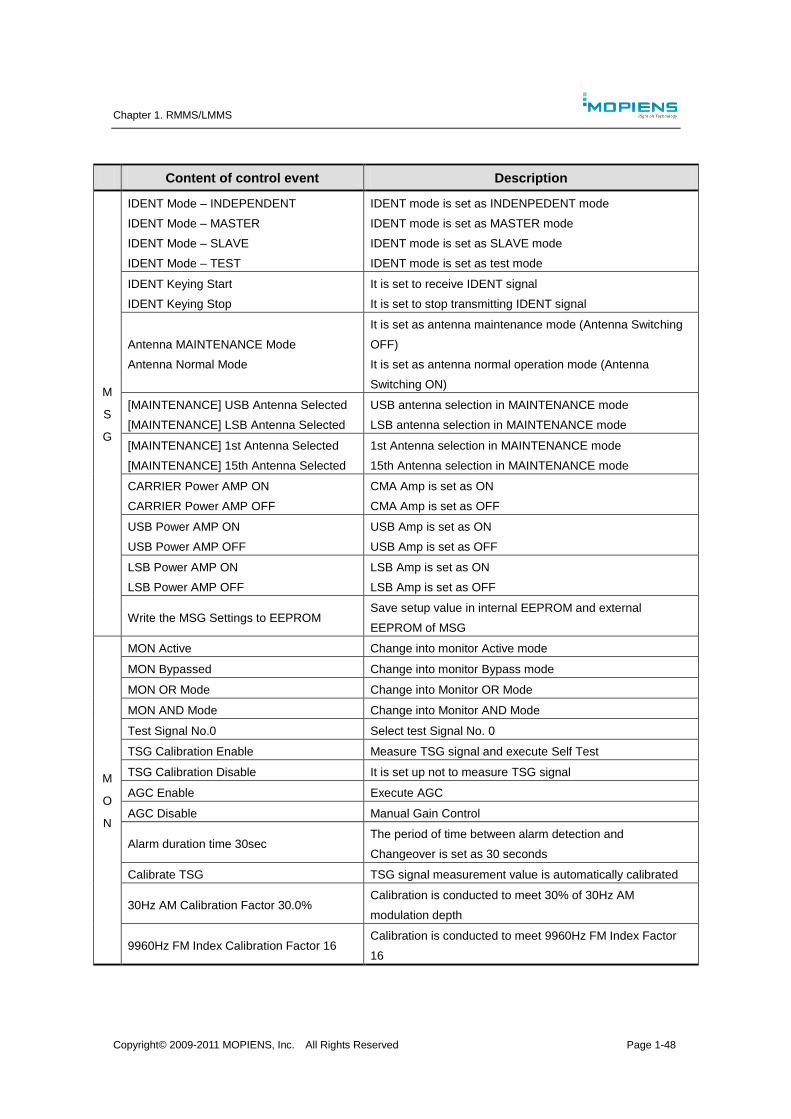
Chapter 1. RMMS/LMMS
Copyright© 2009-2011 MOPIENS, Inc. All Rights Reserved Page 1-48
Content of control event Description
M
S
G
IDENT Mode – INDEPENDENT
IDENT Mode – MASTER
IDENT Mode – SLAVE
IDENT Mode – TEST
IDENT mode is set as INDENPEDENT mode
IDENT mode is set as MASTER mode
IDENT mode is set as SLAVE mode
IDENT mode is set as test mode
IDENT Keying Start
IDENT Keying Stop
It is set to receive IDENT signal
It is set to stop transmitting IDENT signal
Antenna MAINTENANCE Mode
Antenna Normal Mode
It is set as antenna maintenance mode (Antenna Switching
OFF)
It is set as antenna normal operation mode (Antenna
Switching ON)
[MAINTENANCE] USB Antenna Selected
[MAINTENANCE] LSB Antenna Selected
USB antenna selection in MAINTENANCE mode
LSB antenna selection in MAINTENANCE mode
[MAINTENANCE] 1st Antenna Selected
[MAINTENANCE] 15th Antenna Selected
1st Antenna selection in MAINTENANCE mode
15th Antenna selection in MAINTENANCE mode
CARRIER Power AMP ON
CARRIER Power AMP OFF
CMA Amp is set as ON
CMA Amp is set as OFF
USB Power AMP ON
USB Power AMP OFF
USB Amp is set as ON
USB Amp is set as OFF
LSB Power AMP ON
LSB Power AMP OFF
LSB Amp is set as ON
LSB Amp is set as OFF
Write the MSG Settings to EEPROM Save setup value in internal EEPROM and external
EEPROM of MSG
M
O
N
MON Active Change into monitor Active mode
MON Bypassed Change into monitor Bypass mode
MON OR Mode Change into Monitor OR Mode
MON AND Mode Change into Monitor AND Mode
Test Signal No.0 Select test Signal No. 0
TSG Calibration Enable Measure TSG signal and execute Self Test
TSG Calibration Disable It is set up not to measure TSG signal
AGC Enable Execute AGC
AGC Disable Manual Gain Control
Alarm duration time 30sec The period of time between alarm detection and
Changeover is set as 30 seconds
Calibrate TSG TSG signal measurement value is automatically calibrated
30Hz AM Calibration Factor 30.0% Calibration is conducted to meet 30% of 30Hz AM
modulation depth
9960Hz FM Index Calibration Factor 16 Calibration is conducted to meet 9960Hz FM Index Factor
16

Chapter 1. RMMS/LMMS
Copyright© 2009-2011 MOPIENS, Inc. All Rights Reserved Page 1-49
Content of control event Description
M
O
N
9960Hz AM Calibration Factor 10.0% Calibration is conducted to meet 9960Hz AM Modulation
Depth 10.0%
1020Hz AM Calibration Factor 10.0% Calibration is conducted to meet 1020Hz AM Modulation
Depth 10.0%
Azimuth Calibration Factor 0.0degrees Calibration is conducted to calibrate Azimuth
CARRIER Output Power Alarm Upper
Limit 101.0W
Upper and lower limit Alarm value is set up
CARRIER Output Power Alarm Lower
Limit 99.0W
RF Input Level Alarm Upper Limit -1.0dBm
RF Input Level Alarm Lower Limit -
45.0dBm
Azimuth Alarm Upper Limit 179.0degrees
Azimuth Alarm Lower Limit 181.0degrees
Carrier Frequency Alarm Upper Limit
118.3000MHz
Carrier Frequency Alarm Lower Limit
118.2000MHz
USB Frequency Alarm Upper Limit
118.3000MHz
USB Frequency Alarm Lower Limit
118.2000MHz
LSB Frequency Alarm Upper Limit
118.3000MHz
LSB Frequency Alarm Lower Limit
118.2000MHz
30Hz AM Modulation Depth Alarm Upper
Limit 29.0%
30Hz AM Modulation Depth Alarm Lower
Limit 31.0%
9960Hz AM Modulation Depth Alarm
Upper Limit 10.0%
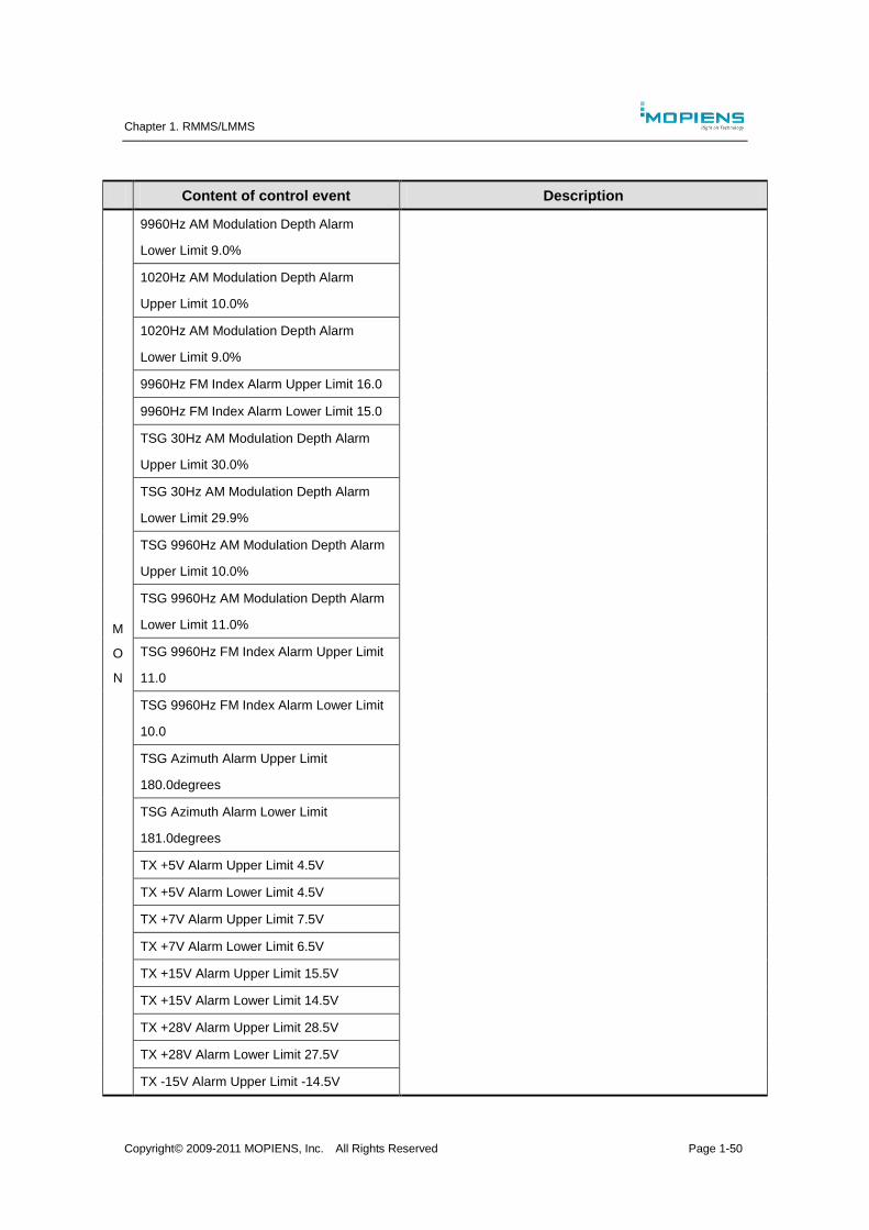
Chapter 1. RMMS/LMMS
Copyright© 2009-2011 MOPIENS, Inc. All Rights Reserved Page 1-50
Content of control event Description
M
O
N
9960Hz AM Modulation Depth Alarm
Lower Limit 9.0%
1020Hz AM Modulation Depth Alarm
Upper Limit 10.0%
1020Hz AM Modulation Depth Alarm
Lower Limit 9.0%
9960Hz FM Index Alarm Upper Limit 16.0
9960Hz FM Index Alarm Lower Limit 15.0
TSG 30Hz AM Modulation Depth Alarm
Upper Limit 30.0%
TSG 30Hz AM Modulation Depth Alarm
Lower Limit 29.9%
TSG 9960Hz AM Modulation Depth Alarm
Upper Limit 10.0%
TSG 9960Hz AM Modulation Depth Alarm
Lower Limit 11.0%
TSG 9960Hz FM Index Alarm Upper Limit
11.0
TSG 9960Hz FM Index Alarm Lower Limit
10.0
TSG Azimuth Alarm Upper Limit
180.0degrees
TSG Azimuth Alarm Lower Limit
181.0degrees
TX +5V Alarm Upper Limit 4.5V
TX +5V Alarm Lower Limit 4.5V
TX +7V Alarm Upper Limit 7.5V
TX +7V Alarm Lower Limit 6.5V
TX +15V Alarm Upper Limit 15.5V
TX +15V Alarm Lower Limit 14.5V
TX +28V Alarm Upper Limit 28.5V
TX +28V Alarm Lower Limit 27.5V
TX -15V Alarm Upper Limit -14.5V
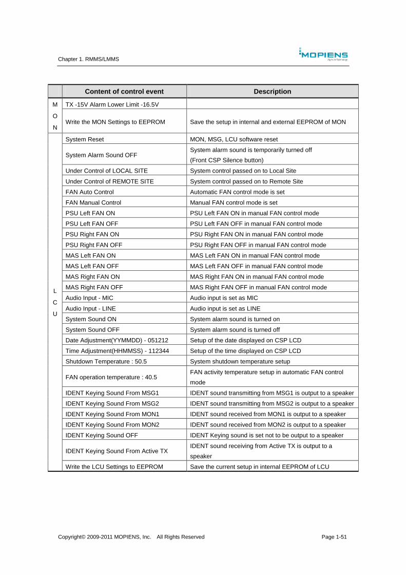
Chapter 1. RMMS/LMMS
Copyright© 2009-2011 MOPIENS, Inc. All Rights Reserved Page 1-51
Content of control event Description
M
O
N
TX -15V Alarm Lower Limit -16.5V
Write the MON Settings to EEPROM Save the setup in internal and external EEPROM of MON
L
C
U
System Reset MON, MSG, LCU software reset
System Alarm Sound OFF System alarm sound is temporarily turned off
(Front CSP Silence button)
Under Control of LOCAL SITE System control passed on to Local Site
Under Control of REMOTE SITE System control passed on to Remote Site
FAN Auto Control Automatic FAN control mode is set
FAN Manual Control Manual FAN control mode is set
PSU Left FAN ON PSU Left FAN ON in manual FAN control mode
PSU Left FAN OFF PSU Left FAN OFF in manual FAN control mode
PSU Right FAN ON PSU Right FAN ON in manual FAN control mode
PSU Right FAN OFF PSU Right FAN OFF in manual FAN control mode
MAS Left FAN ON MAS Left FAN ON in manual FAN control mode
MAS Left FAN OFF MAS Left FAN OFF in manual FAN control mode
MAS Right FAN ON MAS Right FAN ON in manual FAN control mode
MAS Right FAN OFF MAS Right FAN OFF in manual FAN control mode
Audio Input - MIC Audio input is set as MIC
Audio Input - LINE Audio input is set as LINE
System Sound ON System alarm sound is turned on
System Sound OFF System alarm sound is turned off
Date Adjustment(YYMMDD) - 051212 Setup of the date displayed on CSP LCD
Time Adjustment(HHMMSS) - 112344 Setup of the time displayed on CSP LCD
Shutdown Temperature : 50.5 System shutdown temperature setup
FAN operation temperature : 40.5 FAN activity temperature setup in automatic FAN control
mode
IDENT Keying Sound From MSG1 IDENT sound transmitting from MSG1 is output to a speaker
IDENT Keying Sound From MSG2 IDENT sound transmitting from MSG2 is output to a speaker
IDENT Keying Sound From MON1 IDENT sound received from MON1 is output to a speaker
IDENT Keying Sound From MON2 IDENT sound received from MON2 is output to a speaker
IDENT Keying Sound OFF IDENT Keying sound is set not to be output to a speaker
IDENT Keying Sound From Active TX IDENT sound receiving from Active TX is output to a
speaker
Write the LCU Settings to EEPROM Save the current setup in internal EEPROM of LCU
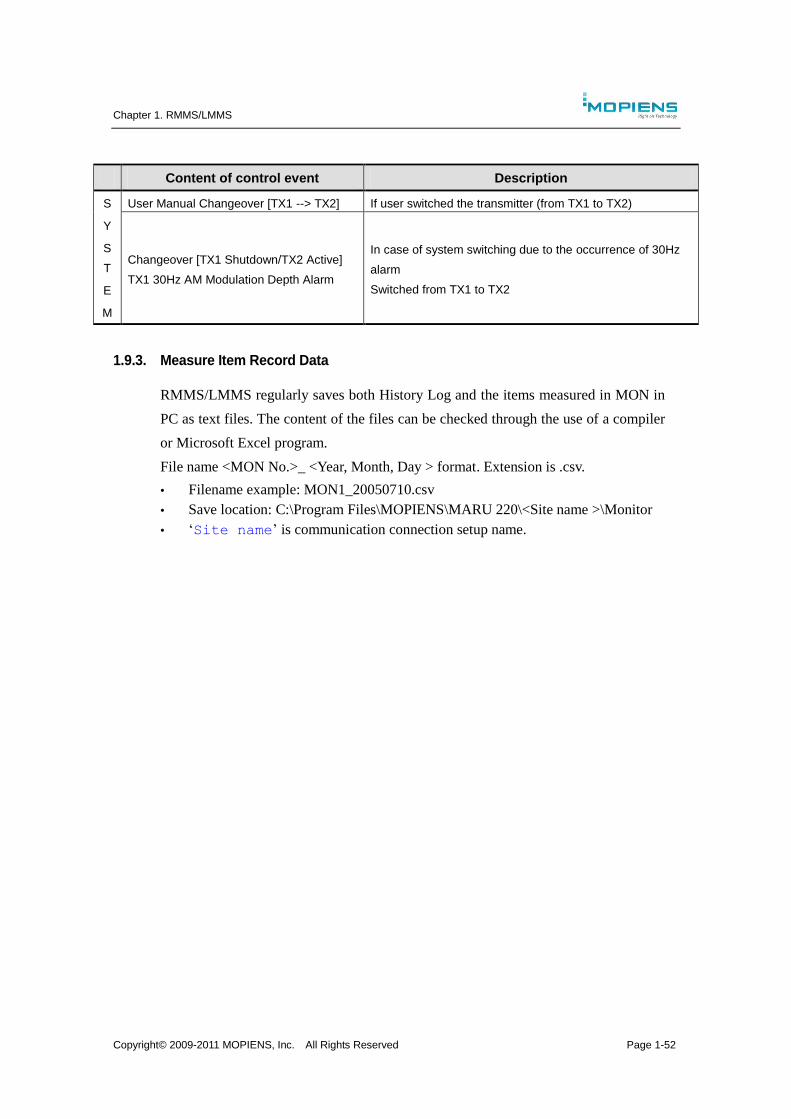
Chapter 1. RMMS/LMMS
Copyright© 2009-2011 MOPIENS, Inc. All Rights Reserved Page 1-52
Content of control event Description
S
Y
S
T
E
M
User Manual Changeover [TX1 --> TX2] If user switched the transmitter (from TX1 to TX2)
Changeover [TX1 Shutdown/TX2 Active]
TX1 30Hz AM Modulation Depth Alarm
In case of system switching due to the occurrence of 30Hz
alarm
Switched from TX1 to TX2
1.9.3. Measure Item Record Data
RMMS/LMMS regularly saves both History Log and the items measured in MON in
PC as text files. The content of the files can be checked through the use of a compiler
or Microsoft Excel program.
File name <MON No.>_ <Year, Month, Day > format. Extension is .csv.
Filename example: MON1_20050710.csv
Save location: C:\Program Files\MOPIENS\MARU 220\<Site name >\Monitor
‘Site name’ is communication connection setup name.
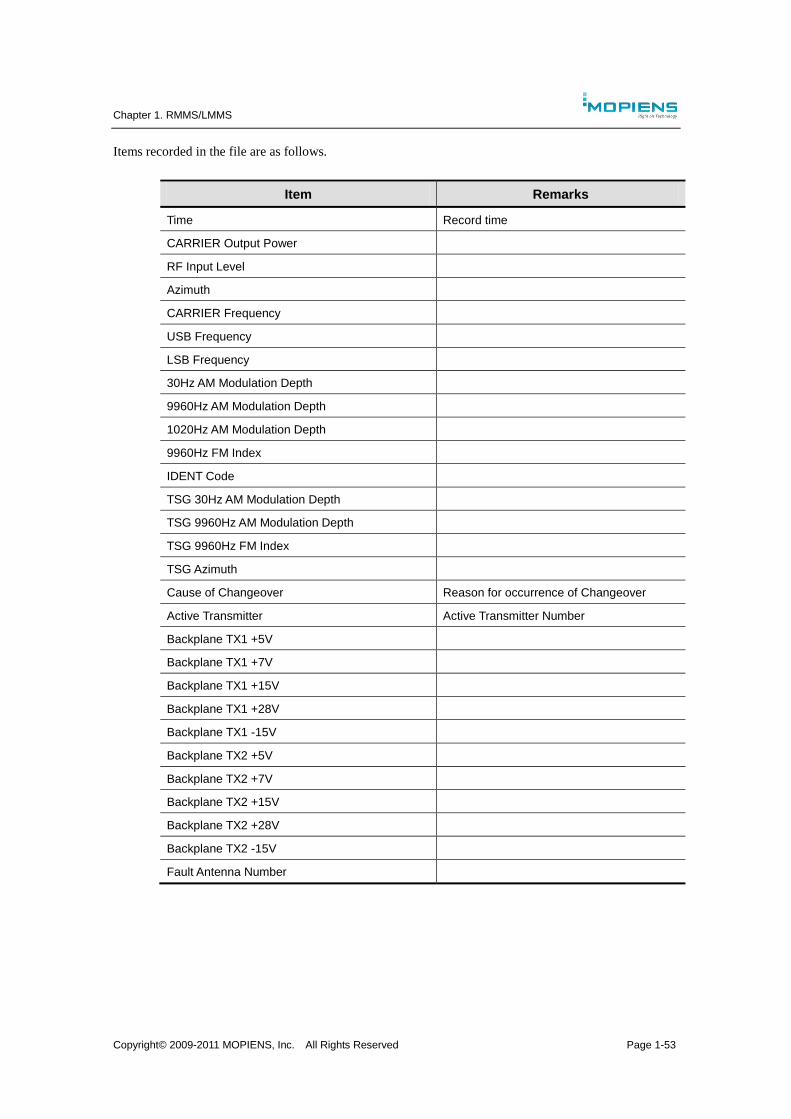
Chapter 1. RMMS/LMMS
Copyright© 2009-2011 MOPIENS, Inc. All Rights Reserved Page 1-53
Items recorded in the file are as follows.
Item Remarks
Time Record time
CARRIER Output Power
RF Input Level
Azimuth
CARRIER Frequency
USB Frequency
LSB Frequency
30Hz AM Modulation Depth
9960Hz AM Modulation Depth
1020Hz AM Modulation Depth
9960Hz FM Index
IDENT Code
TSG 30Hz AM Modulation Depth
TSG 9960Hz AM Modulation Depth
TSG 9960Hz FM Index
TSG Azimuth
Cause of Changeover Reason for occurrence of Changeover
Active Transmitter Active Transmitter Number
Backplane TX1 +5V
Backplane TX1 +7V
Backplane TX1 +15V
Backplane TX1 +28V
Backplane TX1 -15V
Backplane TX2 +5V
Backplane TX2 +7V
Backplane TX2 +15V
Backplane TX2 +28V
Backplane TX2 -15V
Fault Antenna Number
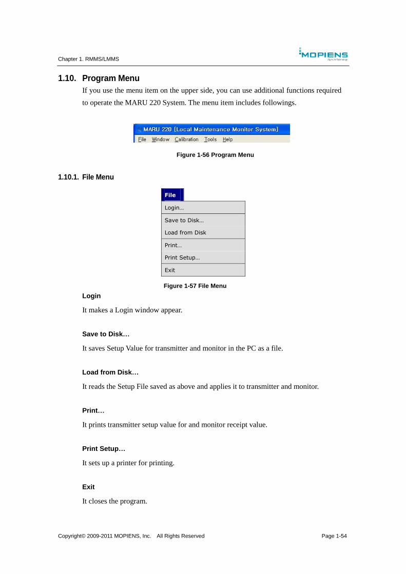
Chapter 1. RMMS/LMMS
Copyright© 2009-2011 MOPIENS, Inc. All Rights Reserved Page 1-54
1.10. Program Menu
If you use the menu item on the upper side, you can use additional functions required
to operate the MARU 220 System. The menu item includes followings.
Figure 1-56 Program Menu
1.10.1. File Menu
File
Login…
Save to Disk…
Load from Disk
Print…
Print Setup…
Exit
Figure 1-57 File Menu
Login
It makes a Login window appear.
Save to Disk…
It saves Setup Value for transmitter and monitor in the PC as a file.
Load from Disk…
It reads the Setup File saved as above and applies it to transmitter and monitor.
Print…
It prints transmitter setup value for and monitor receipt value.
Print Setup…
It sets up a printer for printing.
Exit
It closes the program.
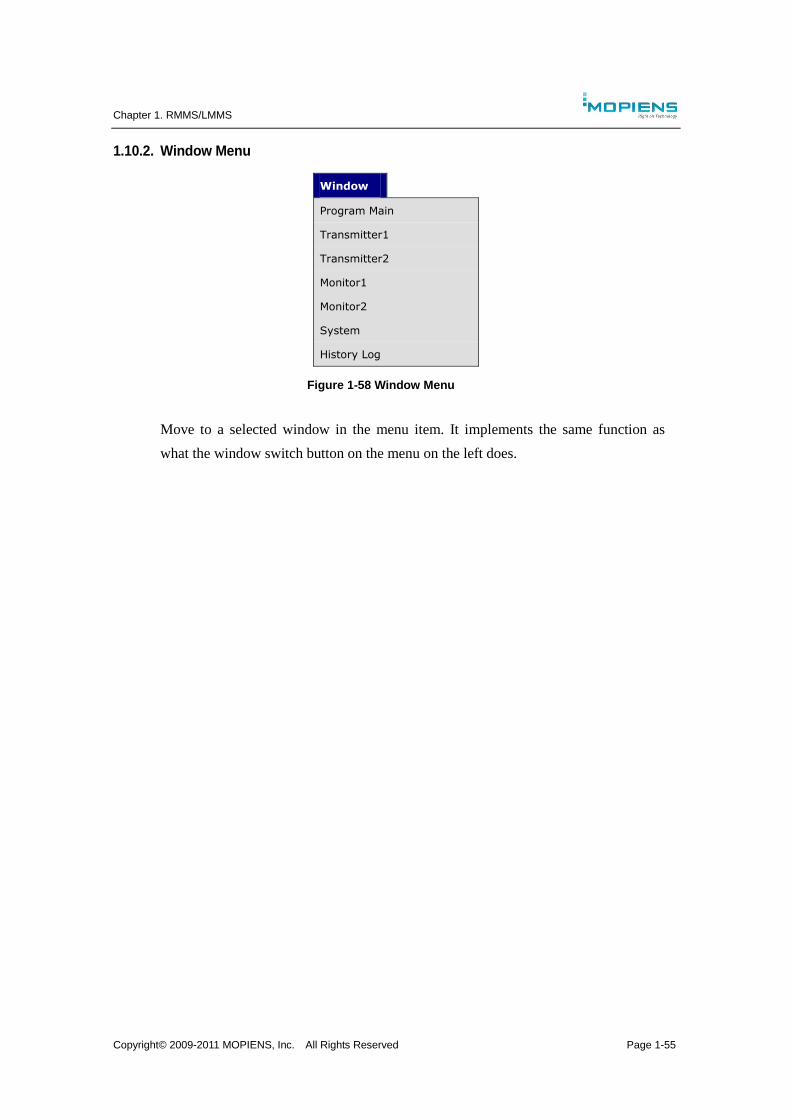
Chapter 1. RMMS/LMMS
Copyright© 2009-2011 MOPIENS, Inc. All Rights Reserved Page 1-55
1.10.2. Window Menu
Window
Program Main
Transmitter1
Transmitter2
Monitor1
Monitor2
System
History Log
Figure 1-58 Window Menu
Move to a selected window in the menu item. It implements the same function as
what the window switch button on the menu on the left does.
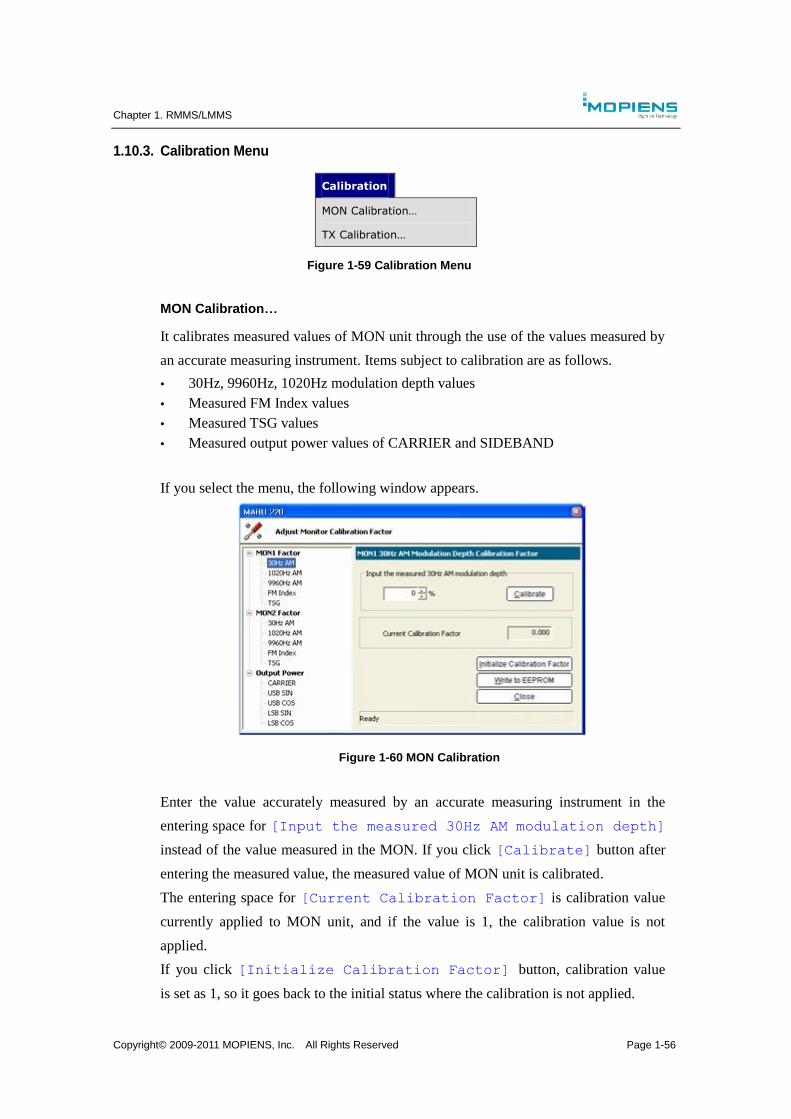
Chapter 1. RMMS/LMMS
Copyright© 2009-2011 MOPIENS, Inc. All Rights Reserved Page 1-56
1.10.3. Calibration Menu
Calibration
MON Calibration…
TX Calibration…
Figure 1-59 Calibration Menu
MON Calibration…
It calibrates measured values of MON unit through the use of the values measured by
an accurate measuring instrument. Items subject to calibration are as follows.
30Hz, 9960Hz, 1020Hz modulation depth values
Measured FM Index values
Measured TSG values
Measured output power values of CARRIER and SIDEBAND
If you select the menu, the following window appears.
Figure 1-60 MON Calibration
Enter the value accurately measured by an accurate measuring instrument in the
entering space for [Input the measured 30Hz AM modulation depth]
instead of the value measured in the MON. If you click [Calibrate] button after
entering the measured value, the measured value of MON unit is calibrated.
The entering space for [Current Calibration Factor] is calibration value
currently applied to MON unit, and if the value is 1, the calibration value is not
applied.
If you click [Initialize Calibration Factor] button, calibration value
is set as 1, so it goes back to the initial status where the calibration is not applied.
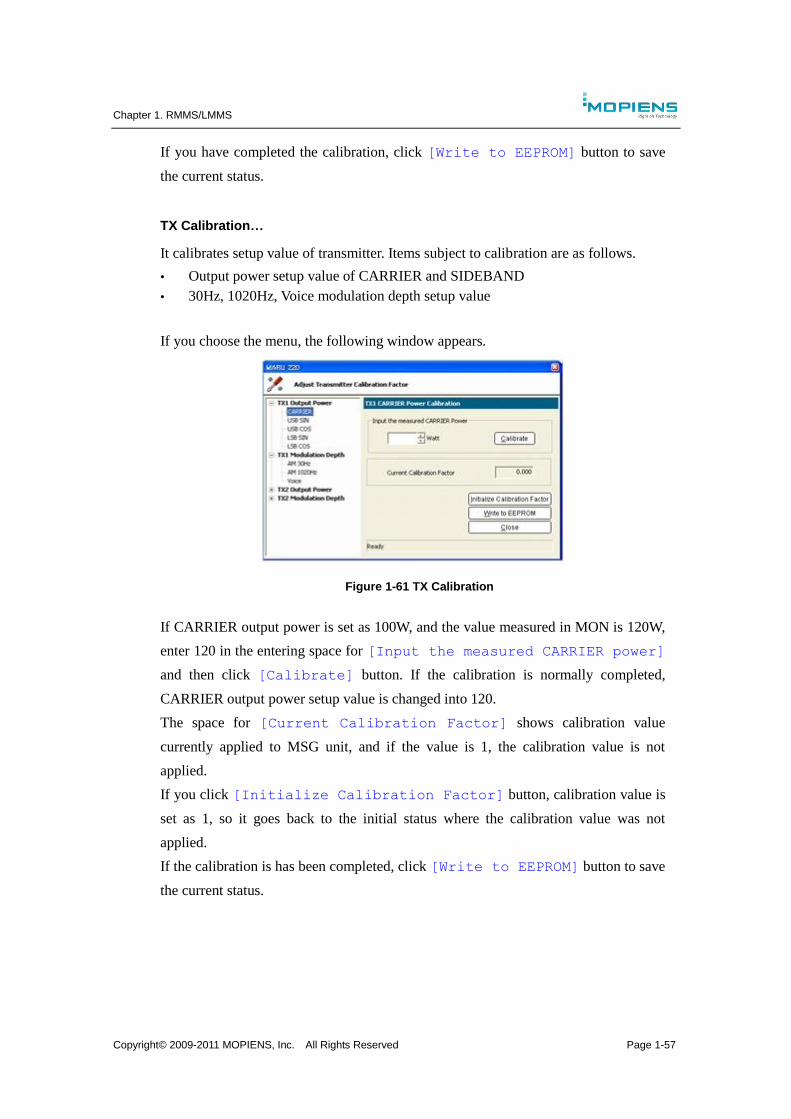
Chapter 1. RMMS/LMMS
Copyright© 2009-2011 MOPIENS, Inc. All Rights Reserved Page 1-57
If you have completed the calibration, click [Write to EEPROM] button to save
the current status.
TX Calibration…
It calibrates setup value of transmitter. Items subject to calibration are as follows.
Output power setup value of CARRIER and SIDEBAND
30Hz, 1020Hz, Voice modulation depth setup value
If you choose the menu, the following window appears.
Figure 1-61 TX Calibration
If CARRIER output power is set as 100W, and the value measured in MON is 120W,
enter 120 in the entering space for [Input the measured CARRIER power]
and then click [Calibrate] button. If the calibration is normally completed,
CARRIER output power setup value is changed into 120.
The space for [Current Calibration Factor] shows calibration value
currently applied to MSG unit, and if the value is 1, the calibration value is not
applied.
If you click [Initialize Calibration Factor] button, calibration value is
set as 1, so it goes back to the initial status where the calibration value was not
applied.
If the calibration is has been completed, click [Write to EEPROM] button to save
the current status.
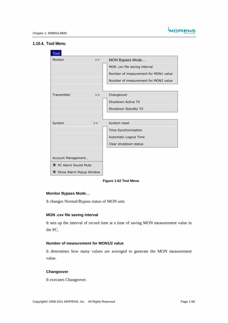
Chapter 1. RMMS/LMMS
Copyright© 2009-2011 MOPIENS, Inc. All Rights Reserved Page 1-58
1.10.4. Tool Menu
Tool
Monitor >>
MON Bypass Mode...
MON .csv file saving interval
Number of measurement for MON1 value
Number of measurement for MON2 value
Transmitter >> Changeover
Shutdown Active TX
Shutdown Standby TX
System >> System reset
Time Synchronization
Automatic Logout Time
Clear shutdown status
Account Management…
▣ PC Alarm Sound Mute
▣ Show Alarm Popup Window
Figure 1-62 Tool Menu
Monitor Bypass Mode…
It changes Normal/Bypass status of MON unit.
MON .csv file saving interval
It sets up the interval of record time at a time of saving MON measurement value in
the PC.
Number of measurement for MON1/2 value
It determines how many values are averaged to generate the MON measurement
value.
Changeover
It executes Changeover.

Chapter 1. RMMS/LMMS
Copyright© 2009-2011 MOPIENS, Inc. All Rights Reserved Page 1-59
Shutdown Active TX
It turns off CARRIER and SIDEBAND AMP of Active Transmitter.
Shutdown Standby TX
It turns off CARRIER and SIDEBAND AMP of Standby Transmitter.
System Reset
It resets the system.
Time Synchronization
It synchronizes time in three locations including LCU, RMMS PC and LMMS PC.
Automatic Logout Time
If a certain period of time passes without user’s control activity in LMMS, automatic
logout is implemented, and the right to control is passed on to RMMS. At that time,
waiting time is set.
Clear Shutdown Status
It clears shutdown status. If MON Bypass is implemented and then it is returned to
Normal status, the same effect can be generated.
Account Management
It is a window to manage RMMS/LMMS users. It creates new accounts and deletes
and changes a password. Account information data is saved in LCU.
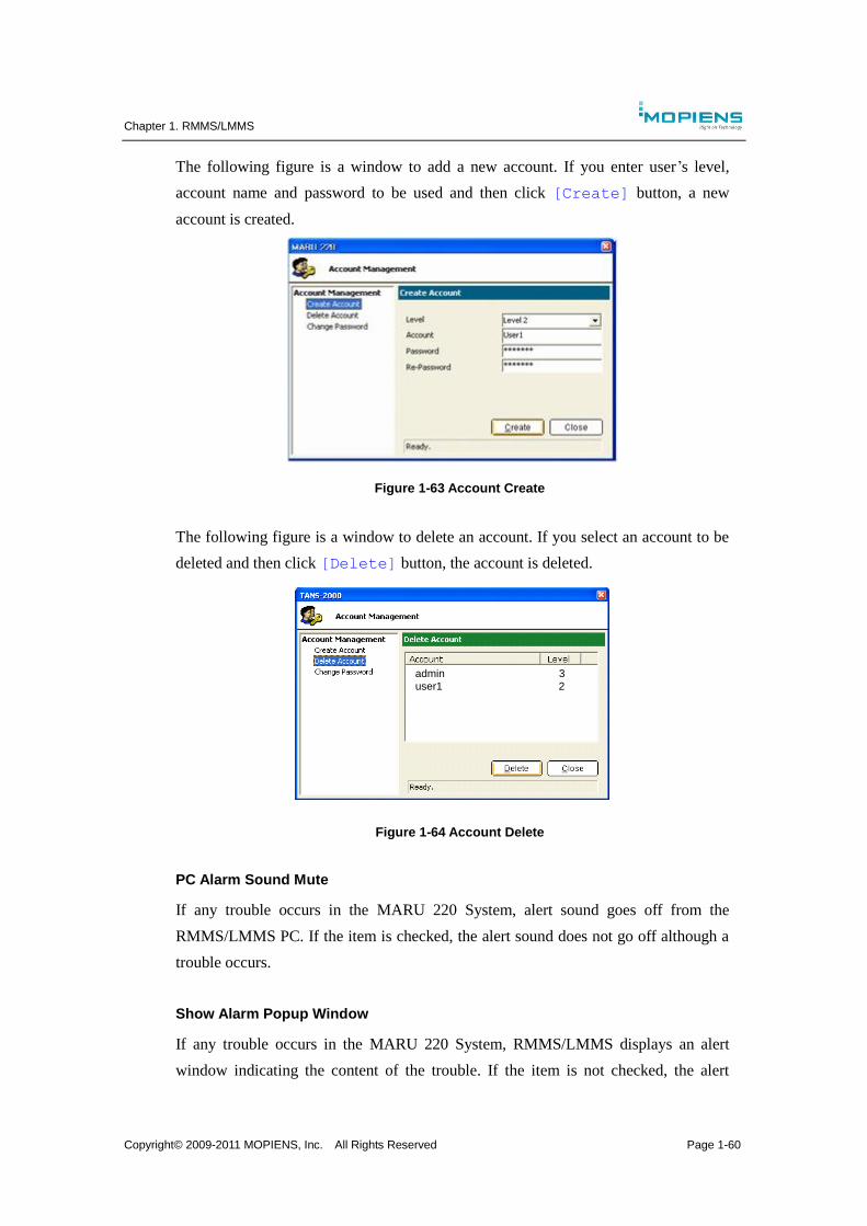
Chapter 1. RMMS/LMMS
Copyright© 2009-2011 MOPIENS, Inc. All Rights Reserved Page 1-60
The following figure is a window to add a new account. If you enter user’s level,
account name and password to be used and then click [Create] button, a new
account is created.
Figure 1-63 Account Create
The following figure is a window to delete an account. If you select an account to be
deleted and then click [Delete] button, the account is deleted.
user1 2
admin 3
Figure 1-64 Account Delete
PC Alarm Sound Mute
If any trouble occurs in the MARU 220 System, alert sound goes off from the
RMMS/LMMS PC. If the item is checked, the alert sound does not go off although a
trouble occurs.
Show Alarm Popup Window
If any trouble occurs in the MARU 220 System, RMMS/LMMS displays an alert
window indicating the content of the trouble. If the item is not checked, the alert

Chapter 1. RMMS/LMMS
Copyright© 2009-2011 MOPIENS, Inc. All Rights Reserved Page 1-61
window is not displayed although a trouble occurs.

Chapter 1. RMMS/LMMS
Copyright© 2009-2011 MOPIENS, Inc. All Rights Reserved Page 1-62
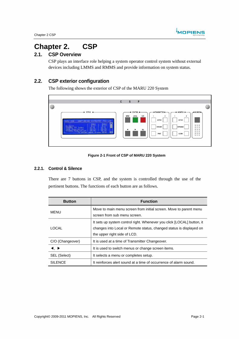
Chapter 2 CSP
Copyright© 2009-2011 MOPIENS, Inc. All Rights Reserved Page 2-1
Chapter 2. CSP 2.1. CSP Overview
CSP plays an interface role helping a system operator control system without external
devices including LMMS and RMMS and provide information on system status.
2.2. CSP exterior configuration
The following shows the exterior of CSP of the MARU 220 System
Figure 2-1 Front of CSP of MARU 220 System
2.2.1. Control & Silence
There are 7 buttons in CSP, and the system is controlled through the use of the
pertinent buttons. The functions of each button are as follows.
Button Function
MENU Move to main menu screen from initial screen. Move to parent menu
screen from sub menu screen.
LOCAL
It sets up system control right. Whenever you click [LOCAL] button, it
changes into Local or Remote status, changed status is displayed on
the upper right side of LCD.
C/O (Changeover) It is used at a time of Transmitter Changeover.
◀, ▶ It is used to switch menus or change screen items.
SEL (Select) It selects a menu or completes setup.
SILENCE It reinforces alert sound at a time of occurrence of alarm sound.
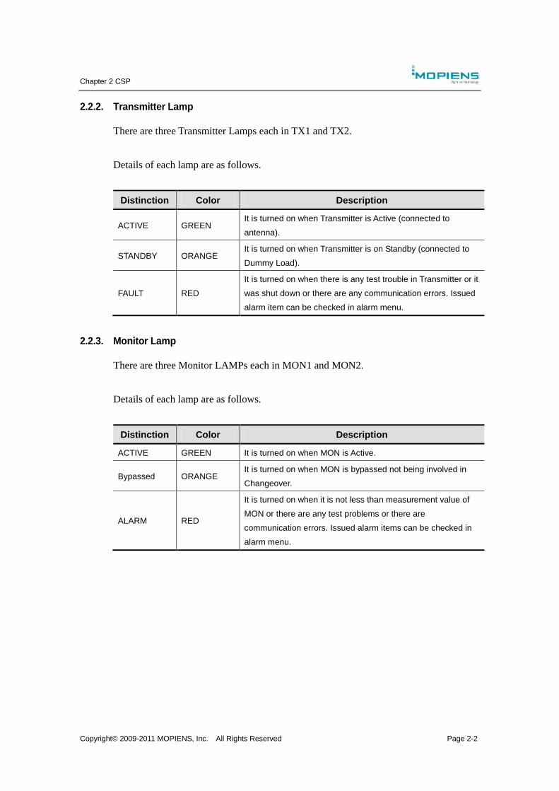
Chapter 2 CSP
Copyright© 2009-2011 MOPIENS, Inc. All Rights Reserved Page 2-2
2.2.2. Transmitter Lamp
There are three Transmitter Lamps each in TX1 and TX2.
Details of each lamp are as follows.
Distinction Color Description
ACTIVE GREEN It is turned on when Transmitter is Active (connected to
antenna).
STANDBY ORANGE It is turned on when Transmitter is on Standby (connected to
Dummy Load).
FAULT RED
It is turned on when there is any test trouble in Transmitter or it
was shut down or there are any communication errors. Issued
alarm item can be checked in alarm menu.
2.2.3. Monitor Lamp
There are three Monitor LAMPs each in MON1 and MON2.
Details of each lamp are as follows.
Distinction Color Description
ACTIVE GREEN It is turned on when MON is Active.
Bypassed ORANGE It is turned on when MON is bypassed not being involved in
Changeover.
ALARM RED
It is turned on when it is not less than measurement value of
MON or there are any test problems or there are
communication errors. Issued alarm items can be checked in
alarm menu.

Chapter 2 CSP
Copyright© 2009-2011 MOPIENS, Inc. All Rights Reserved Page 2-3
2.3. Characteristics of CSP
CSP menu consists of main screen and 6 menus.
The main screen provides basic system information measured by MON. Azimuth,
9960Hz FM Index, 30Hz Modulation, 9960Hz Modulation, 1020Hz Modulation,
CAR Output Power and RF Input Level are displayed.
Figure 2-2 Main Screen Composition
Menu Description
Quick Menu
It is Shortcut Menu that enables users to implement setup without going into
sub menu several times at a time of operation of device through CSP. Menu
item can be added or deleted through user setup. Basic menus include MON
Bypass, Shutdown Main, Shutdown Standby, Add Menu and Delete Menu.
Alarm
It displays alarm status and BITE status of each unit. Alarm menu includes
Transmitter1, Transmitter2, Monitor 1, Monitor 2, Presence Detect, System,
Power Supply and Environment, and the alarm status and the BITE status can
be checked respectively.
Transmitter The frequency of the system and general signals can be set. Transmitter menu
consists of TX1, TX2 and CONFIG.
Monitor It displays results measured in MON1 and MON2. Monitor menu consists of
MON1, MON2 and CONFIG.
System
It can save or restore system setup value and inquire or set up system status
such as Changeover, antenna control, FAN control and system temperature.
System menu consists of Save & Restore, System Control, Changeover, FAN
Control, Presence Detect, Temperature, Environment, Audio, DME Interface
and LCU Configuration.
Power Supply It can inquire PSS status. Power Supply Menu consists of PSU Status and
PSU Measurement.
Information It displays status information of each unit. Sub menu consists of Date & Time,
LCU, MSG1, MSG2, MON1 and MON2.
Main Window
Quick Menu Alarm Transmitter Monitor System Power
Supply Information
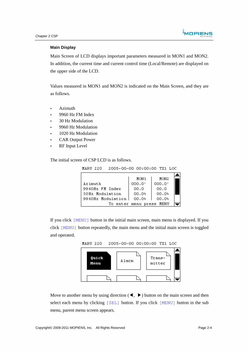
Chapter 2 CSP
Copyright© 2009-2011 MOPIENS, Inc. All Rights Reserved Page 2-4
Main Display
Main Screen of LCD displays important parameters measured in MON1 and MON2.
In addition, the current time and current control time (Local/Remote) are displayed on
the upper side of the LCD.
Values measured in MON1 and MON2 is indicated on the Main Screen, and they are
as follows.
Azimuth
9960 Hz FM Index
30 Hz Modulation
9960 Hz Modulation
1020 Hz Modulation
CAR Output Power
RF Input Level
The initial screen of CSP LCD is as follows.
If you click [MENU] button in the initial main screen, main menu is displayed. If you
click [MENU] button repeatedly, the main menu and the initial main screen is toggled
and operated.
Move to another menu by using direction (◀, ▶) button on the main screen and then
select each menu by clicking [SEL] button. If you click [MENU] button in the sub
menu, parent menu screen appears.
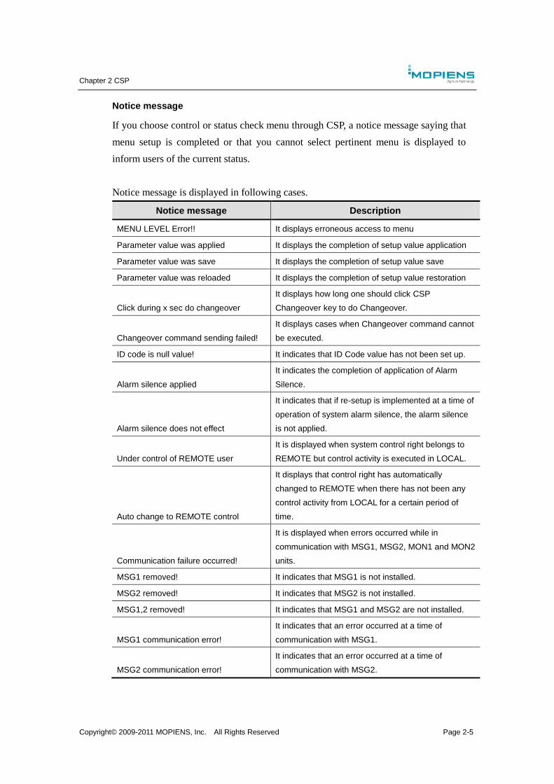
Chapter 2 CSP
Copyright© 2009-2011 MOPIENS, Inc. All Rights Reserved Page 2-5
Notice message
If you choose control or status check menu through CSP, a notice message saying that
menu setup is completed or that you cannot select pertinent menu is displayed to
inform users of the current status.
Notice message is displayed in following cases.
Notice message Description
MENU LEVEL Error!! It displays erroneous access to menu
Parameter value was applied It displays the completion of setup value application
Parameter value was save It displays the completion of setup value save
Parameter value was reloaded It displays the completion of setup value restoration
Click during x sec do changeover
It displays how long one should click CSP
Changeover key to do Changeover.
Changeover command sending failed!
It displays cases when Changeover command cannot
be executed.
ID code is null value! It indicates that ID Code value has not been set up.
Alarm silence applied
It indicates the completion of application of Alarm
Silence.
Alarm silence does not effect
It indicates that if re-setup is implemented at a time of
operation of system alarm silence, the alarm silence
is not applied.
Under control of REMOTE user
It is displayed when system control right belongs to
REMOTE but control activity is executed in LOCAL.
Auto change to REMOTE control
It displays that control right has automatically
changed to REMOTE when there has not been any
control activity from LOCAL for a certain period of
time.
Communication failure occurred!
It is displayed when errors occurred while in
communication with MSG1, MSG2, MON1 and MON2
units.
MSG1 removed! It indicates that MSG1 is not installed.
MSG2 removed! It indicates that MSG2 is not installed.
MSG1,2 removed! It indicates that MSG1 and MSG2 are not installed.
MSG1 communication error!
It indicates that an error occurred at a time of
communication with MSG1.
MSG2 communication error!
It indicates that an error occurred at a time of
communication with MSG2.
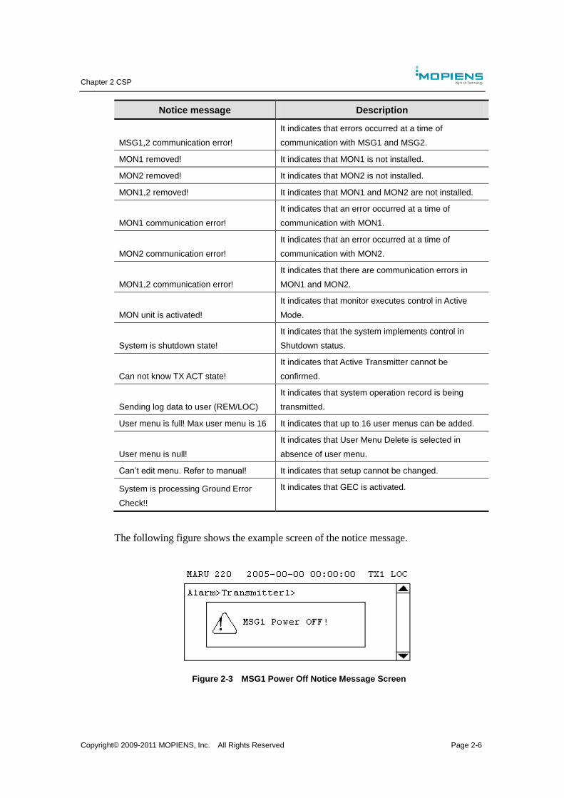
Chapter 2 CSP
Copyright© 2009-2011 MOPIENS, Inc. All Rights Reserved Page 2-6
Notice message Description
MSG1,2 communication error!
It indicates that errors occurred at a time of
communication with MSG1 and MSG2.
MON1 removed! It indicates that MON1 is not installed.
MON2 removed! It indicates that MON2 is not installed.
MON1,2 removed! It indicates that MON1 and MON2 are not installed.
MON1 communication error!
It indicates that an error occurred at a time of
communication with MON1.
MON2 communication error!
It indicates that an error occurred at a time of
communication with MON2.
MON1,2 communication error!
It indicates that there are communication errors in
MON1 and MON2.
MON unit is activated!
It indicates that monitor executes control in Active
Mode.
System is shutdown state!
It indicates that the system implements control in
Shutdown status.
Can not know TX ACT state!
It indicates that Active Transmitter cannot be
confirmed.
Sending log data to user (REM/LOC)
It indicates that system operation record is being
transmitted.
User menu is full! Max user menu is 16 It indicates that up to 16 user menus can be added.
User menu is null!
It indicates that User Menu Delete is selected in
absence of user menu.
Can’t edit menu. Refer to manual! It indicates that setup cannot be changed.
System is processing Ground Error
Check!!
It indicates that GEC is activated.
The following figure shows the example screen of the notice message.
Figure 2-3 MSG1 Power Off Notice Message Screen
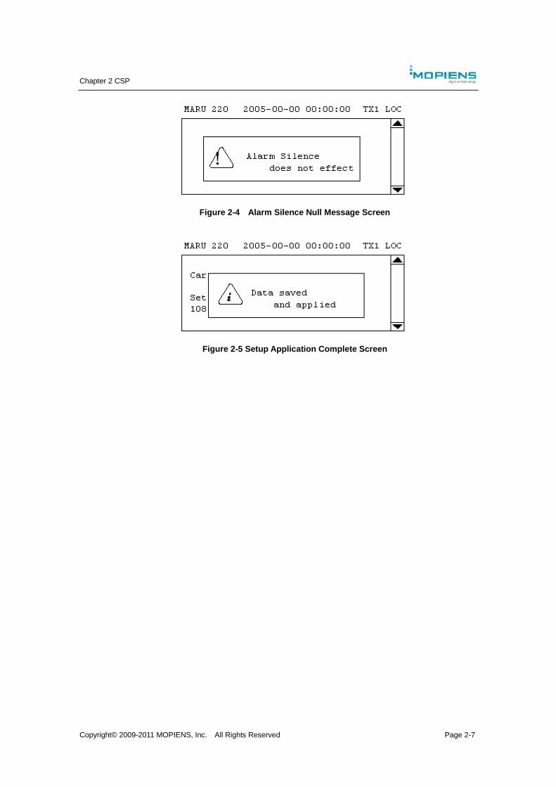
Chapter 2 CSP
Copyright© 2009-2011 MOPIENS, Inc. All Rights Reserved Page 2-7
Figure 2-4 Alarm Silence Null Message Screen
Figure 2-5 Setup Application Complete Screen
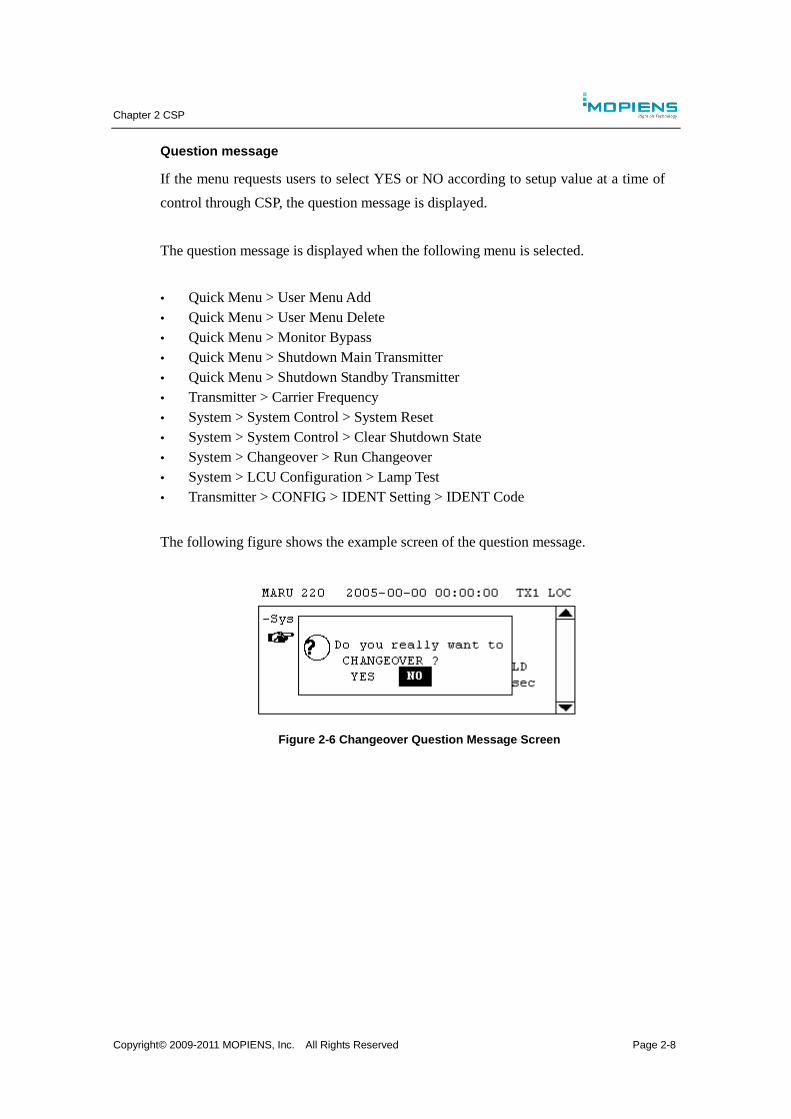
Chapter 2 CSP
Copyright© 2009-2011 MOPIENS, Inc. All Rights Reserved Page 2-8
Question message
If the menu requests users to select YES or NO according to setup value at a time of
control through CSP, the question message is displayed.
The question message is displayed when the following menu is selected.
Quick Menu > User Menu Add
Quick Menu > User Menu Delete
Quick Menu > Monitor Bypass
Quick Menu > Shutdown Main Transmitter
Quick Menu > Shutdown Standby Transmitter
Transmitter > Carrier Frequency
System > System Control > System Reset
System > System Control > Clear Shutdown State
System > Changeover > Run Changeover
System > LCU Configuration > Lamp Test
Transmitter > CONFIG > IDENT Setting > IDENT Code
The following figure shows the example screen of the question message.
Figure 2-6 Changeover Question Message Screen
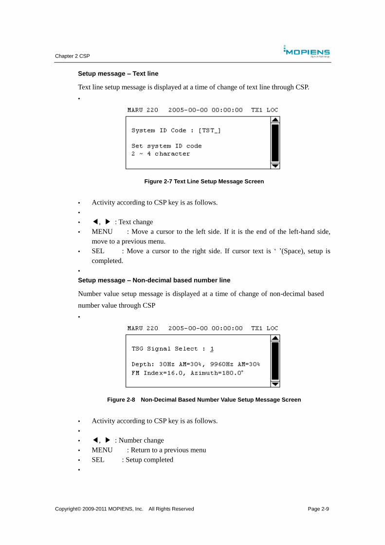
Chapter 2 CSP
Copyright© 2009-2011 MOPIENS, Inc. All Rights Reserved Page 2-9
Setup message – Text line
Text line setup message is displayed at a time of change of text line through CSP.
Figure 2-7 Text Line Setup Message Screen
Activity according to CSP key is as follows.
◀, ▶ : Text change
MENU : Move a cursor to the left side. If it is the end of the left-hand side,
move to a previous menu.
SEL : Move a cursor to the right side. If cursor text is ‘ ’(Space), setup is
completed.
Setup message – Non-decimal based number line
Number value setup message is displayed at a time of change of non-decimal based
number value through CSP
Figure 2-8 Non-Decimal Based Number Value Setup Message Screen
Activity according to CSP key is as follows.
◀, ▶ : Number change
MENU : Return to a previous menu
SEL : Setup completed
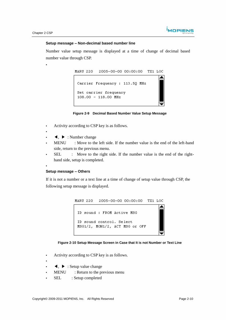
Chapter 2 CSP
Copyright© 2009-2011 MOPIENS, Inc. All Rights Reserved Page 2-10
Setup message – Non-decimal based number line
Number value setup message is displayed at a time of change of decimal based
number value through CSP.
Figure 2-9 Decimal Based Number Value Setup Message
Activity according to CSP key is as follows.
◀, ▶ : Number change
MENU : Move to the left side. If the number value is the end of the left-hand
side, return to the previous menu.
SEL : Move to the right side. If the number value is the end of the right-
hand side, setup is completed.
Setup message – Others
If it is not a number or a text line at a time of change of setup value through CSP, the
following setup message is displayed.
Figure 2-10 Setup Message Screen in Case that It is not Number or Text Line
Activity according to CSP key is as follows.
◀, ▶ : Setup value change
MENU : Return to the previous menu
SEL : Setup completed
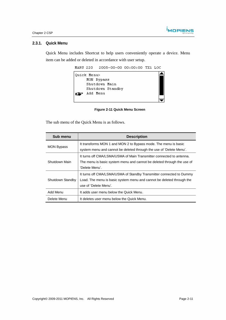
Chapter 2 CSP
Copyright© 2009-2011 MOPIENS, Inc. All Rights Reserved Page 2-11
2.3.1. Quick Menu
Quick Menu includes Shortcut to help users conveniently operate a device. Menu
item can be added or deleted in accordance with user setup.
Figure 2-11 Quick Menu Screen
The sub menu of the Quick Menu is as follows.
Sub menu Description
MON Bypass It transforms MON 1 and MON 2 to Bypass mode. The menu is basic
system menu and cannot be deleted through the use of ‘Delete Menu’.
Shutdown Main
It turns off CMA/LSMA/USMA of Main Transmitter connected to antenna.
The menu is basic system menu and cannot be deleted through the use of
‘Delete Menu’.
Shutdown Standby
It turns off CMA/LSMA/USMA of Standby Transmitter connected to Dummy
Load. The menu is basic system menu and cannot be deleted through the
use of ‘Delete Menu’.
Add Menu It adds user menu below the Quick Menu.
Delete Menu It deletes user menu below the Quick Menu.
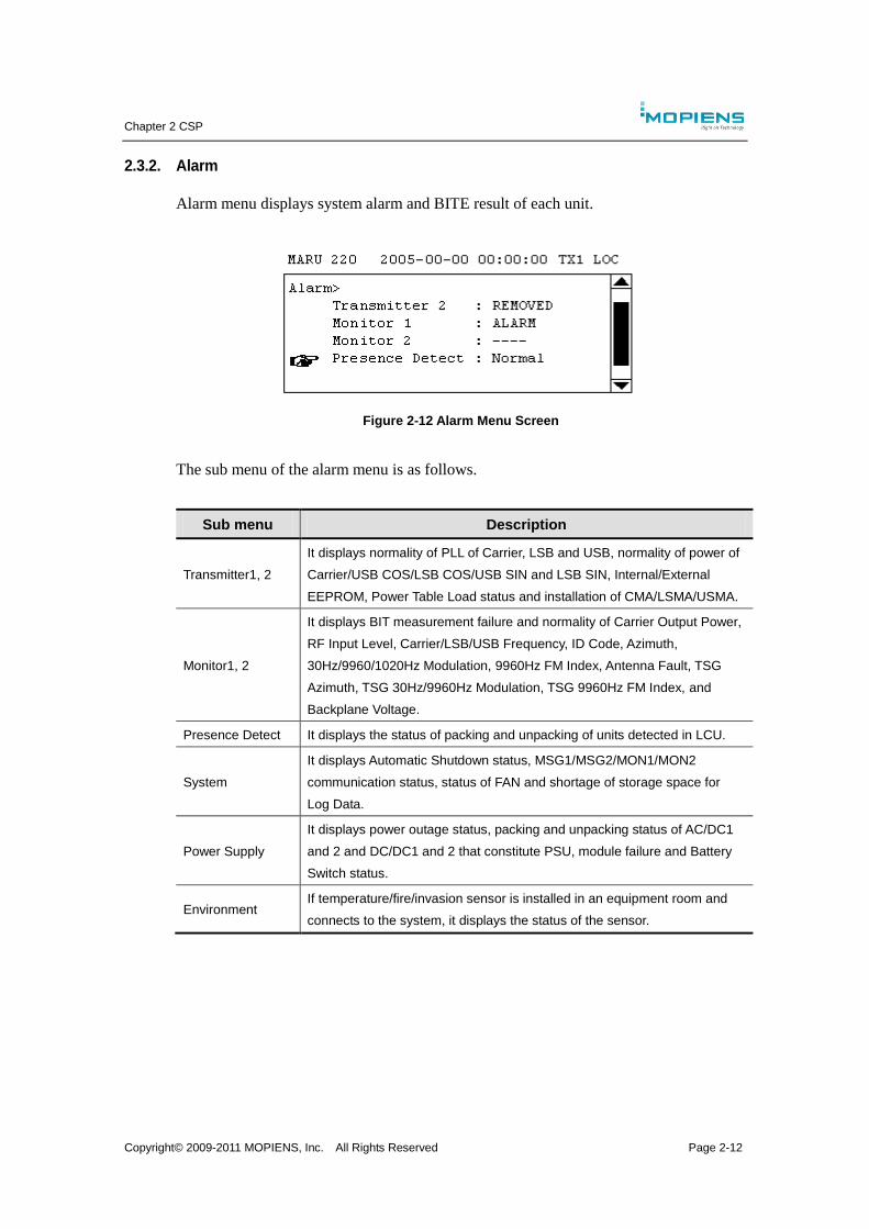
Chapter 2 CSP
Copyright© 2009-2011 MOPIENS, Inc. All Rights Reserved Page 2-12
2.3.2. Alarm
Alarm menu displays system alarm and BITE result of each unit.
Figure 2-12 Alarm Menu Screen
The sub menu of the alarm menu is as follows.
Sub menu Description
Transmitter1, 2
It displays normality of PLL of Carrier, LSB and USB, normality of power of
Carrier/USB COS/LSB COS/USB SIN and LSB SIN, Internal/External
EEPROM, Power Table Load status and installation of CMA/LSMA/USMA.
Monitor1, 2
It displays BIT measurement failure and normality of Carrier Output Power,
RF Input Level, Carrier/LSB/USB Frequency, ID Code, Azimuth,
30Hz/9960/1020Hz Modulation, 9960Hz FM Index, Antenna Fault, TSG
Azimuth, TSG 30Hz/9960Hz Modulation, TSG 9960Hz FM Index, and
Backplane Voltage.
Presence Detect It displays the status of packing and unpacking of units detected in LCU.
System
It displays Automatic Shutdown status, MSG1/MSG2/MON1/MON2
communication status, status of FAN and shortage of storage space for
Log Data.
Power Supply
It displays power outage status, packing and unpacking status of AC/DC1
and 2 and DC/DC1 and 2 that constitute PSU, module failure and Battery
Switch status.
Environment If temperature/fire/invasion sensor is installed in an equipment room and
connects to the system, it displays the status of the sensor.
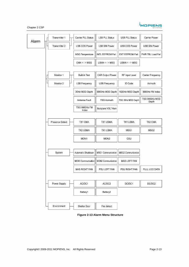
Chapter 2 CSP
Copyright© 2009-2011 MOPIENS, Inc. All Rights Reserved Page 2-13
Figure 2-13 Alarm Menu Structure
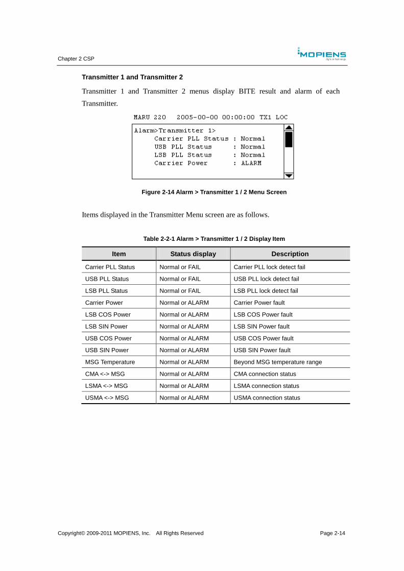
Chapter 2 CSP
Copyright© 2009-2011 MOPIENS, Inc. All Rights Reserved Page 2-14
Transmitter 1 and Transmitter 2
Transmitter 1 and Transmitter 2 menus display BITE result and alarm of each
Transmitter.
Figure 2-14 Alarm > Transmitter 1 / 2 Menu Screen
Items displayed in the Transmitter Menu screen are as follows.
Table 2-2-1 Alarm > Transmitter 1 / 2 Display Item
Item Status display Description
Carrier PLL Status Normal or FAIL Carrier PLL lock detect fail
USB PLL Status Normal or FAIL USB PLL lock detect fail
LSB PLL Status Normal or FAIL LSB PLL lock detect fail
Carrier Power Normal or ALARM Carrier Power fault
LSB COS Power Normal or ALARM LSB COS Power fault
LSB SIN Power Normal or ALARM LSB SIN Power fault
USB COS Power Normal or ALARM USB COS Power fault
USB SIN Power Normal or ALARM USB SIN Power fault
MSG Temperature Normal or ALARM Beyond MSG temperature range
CMA <-> MSG Normal or ALARM CMA connection status
LSMA <-> MSG Normal or ALARM LSMA connection status
USMA <-> MSG Normal or ALARM USMA connection status
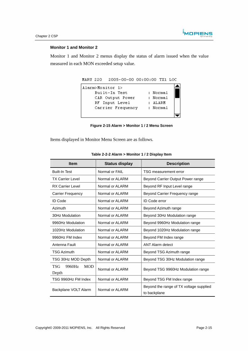
Chapter 2 CSP
Copyright© 2009-2011 MOPIENS, Inc. All Rights Reserved Page 2-15
Monitor 1 and Monitor 2
Monitor 1 and Monitor 2 menus display the status of alarm issued when the value
measured in each MON exceeded setup value.
Figure 2-15 Alarm > Monitor 1 / 2 Menu Screen
Items displayed in Monitor Menu Screen are as follows.
Table 2-2-2 Alarm > Monitor 1 / 2 Display Item
Item Status display Description
Built-In Test Normal or FAIL TSG measurement error
TX Carrier Level Normal or ALARM Beyond Carrier Output Power range
RX Carrier Level Normal or ALARM Beyond RF Input Level range
Carrier Frequency Normal or ALARM Beyond Carrier Frequency range
ID Code Normal or ALARM ID Code error
Azimuth Normal or ALARM Beyond Azimuth range
30Hz Modulation Normal or ALARM Beyond 30Hz Modulation range
9960Hz Modulation Normal or ALARM Beyond 9960Hz Modulation range
1020Hz Modulation Normal or ALARM Beyond 1020Hz Modulation range
9960Hz FM Index Normal or ALARM Beyond FM Index range
Antenna Fault Normal or ALARM ANT Alarm detect
TSG Azimuth Normal or ALARM Beyond TSG Azimuth range
TSG 30Hz MOD Depth Normal or ALARM Beyond TSG 30Hz Modulation range
TSG 9960Hz MOD
Depth Normal or ALARM Beyond TSG 9960Hz Modulation range
TSG 9960Hz FM Index Normal or ALARM Beyond TSG FM Index range
Backplane VOLT Alarm Normal or ALARM Beyond the range of TX voltage supplied
to backplane
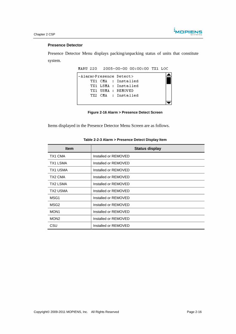
Chapter 2 CSP
Copyright© 2009-2011 MOPIENS, Inc. All Rights Reserved Page 2-16
Presence Detector
Presence Detector Menu displays packing/unpacking status of units that constitute
system.
Figure 2-16 Alarm > Presence Detect Screen
Items displayed in the Presence Detector Menu Screen are as follows.
Table 2-2-3 Alarm > Presence Detect Display Item
Item Status display
TX1 CMA Installed or REMOVED
TX1 LSMA Installed or REMOVED
TX1 USMA Installed or REMOVED
TX2 CMA Installed or REMOVED
TX2 LSMA Installed or REMOVED
TX2 USMA Installed or REMOVED
MSG1 Installed or REMOVED
MSG2 Installed or REMOVED
MON1 Installed or REMOVED
MON2 Installed or REMOVED
CSU Installed or REMOVED
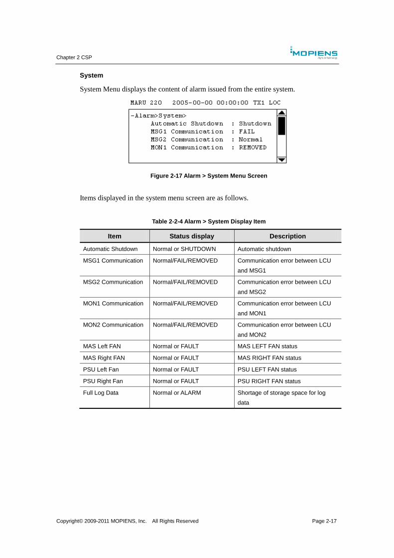
Chapter 2 CSP
Copyright© 2009-2011 MOPIENS, Inc. All Rights Reserved Page 2-17
System
System Menu displays the content of alarm issued from the entire system.
Figure 2-17 Alarm > System Menu Screen
Items displayed in the system menu screen are as follows.
Table 2-2-4 Alarm > System Display Item
Item Status display Description
Automatic Shutdown Normal or SHUTDOWN Automatic shutdown
MSG1 Communication Normal/FAIL/REMOVED Communication error between LCU
and MSG1
MSG2 Communication Normal/FAIL/REMOVED Communication error between LCU
and MSG2
MON1 Communication Normal/FAIL/REMOVED Communication error between LCU
and MON1
MON2 Communication Normal/FAIL/REMOVED Communication error between LCU
and MON2
MAS Left FAN Normal or FAULT MAS LEFT FAN status
MAS Right FAN Normal or FAULT MAS RIGHT FAN status
PSU Left Fan Normal or FAULT PSU LEFT FAN status
PSU Right Fan Normal or FAULT PSU RIGHT FAN status
Full Log Data Normal or ALARM Shortage of storage space for log
data
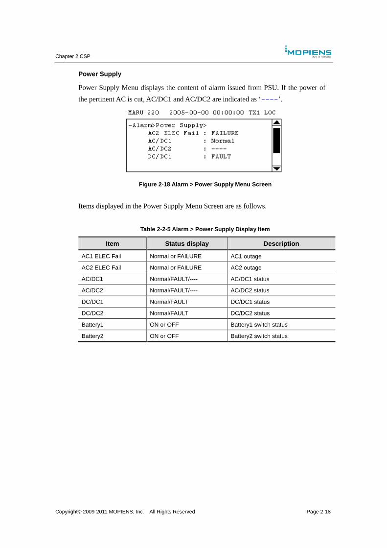
Chapter 2 CSP
Copyright© 2009-2011 MOPIENS, Inc. All Rights Reserved Page 2-18
Power Supply
Power Supply Menu displays the content of alarm issued from PSU. If the power of
the pertinent AC is cut, AC/DC1 and AC/DC2 are indicated as ‘----’.
Figure 2-18 Alarm > Power Supply Menu Screen
Items displayed in the Power Supply Menu Screen are as follows.
Table 2-2-5 Alarm > Power Supply Display Item
Item Status display Description
AC1 ELEC Fail Normal or FAILURE AC1 outage
AC2 ELEC Fail Normal or FAILURE AC2 outage
AC/DC1 Normal/FAULT/---- AC/DC1 status
AC/DC2 Normal/FAULT/---- AC/DC2 status
DC/DC1 Normal/FAULT DC/DC1 status
DC/DC2 Normal/FAULT DC/DC2 status
Battery1 ON or OFF Battery1 switch status
Battery2 ON or OFF Battery2 switch status
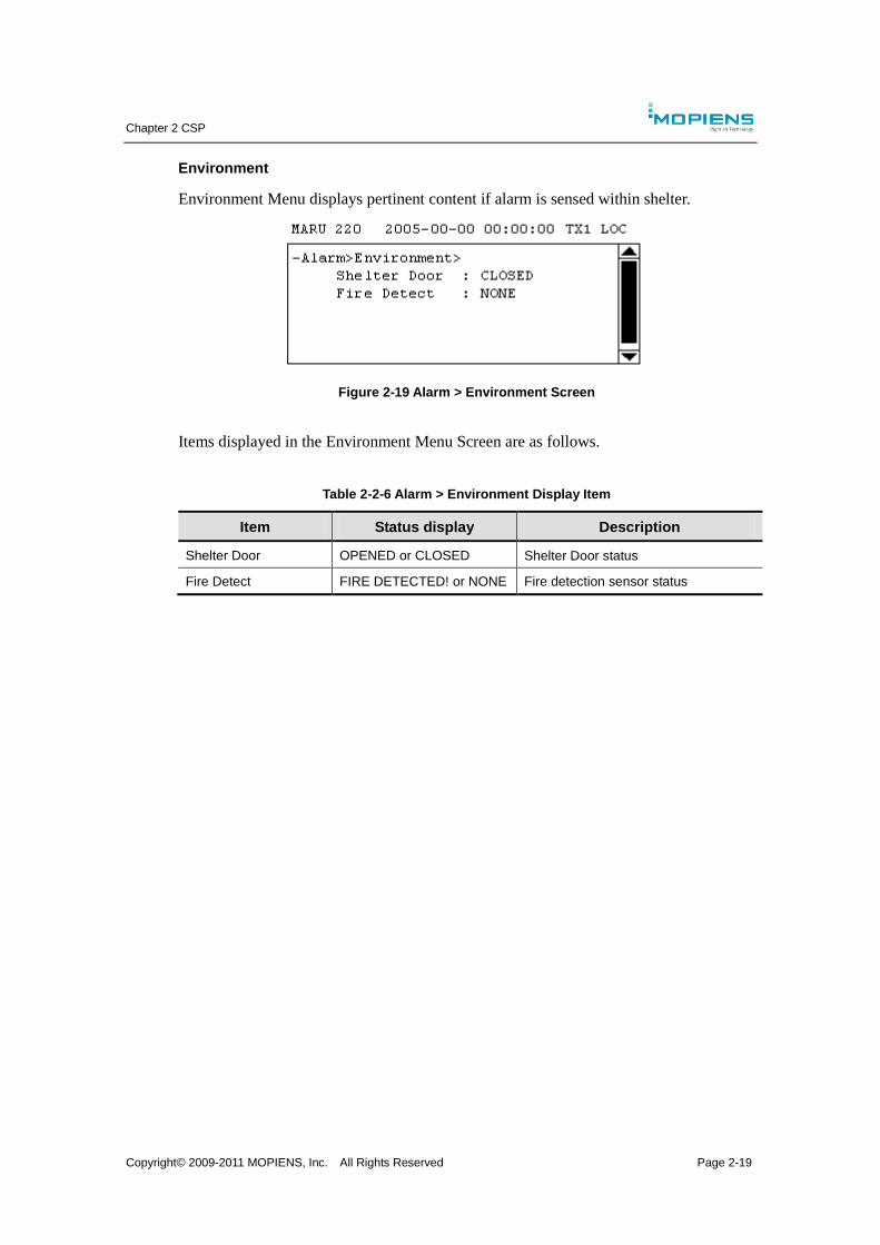
Chapter 2 CSP
Copyright© 2009-2011 MOPIENS, Inc. All Rights Reserved Page 2-19
Environment
Environment Menu displays pertinent content if alarm is sensed within shelter.
Figure 2-19 Alarm > Environment Screen
Items displayed in the Environment Menu Screen are as follows.
Table 2-2-6 Alarm > Environment Display Item
Item Status display Description
Shelter Door OPENED or CLOSED Shelter Door status
Fire Detect FIRE DETECTED! or NONE Fire detection sensor status
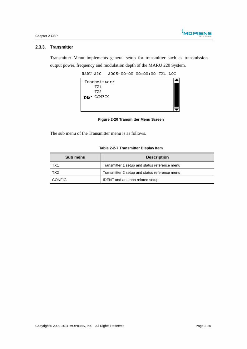
Chapter 2 CSP
Copyright© 2009-2011 MOPIENS, Inc. All Rights Reserved Page 2-20
2.3.3. Transmitter
Transmitter Menu implements general setup for transmitter such as transmission
output power, frequency and modulation depth of the MARU 220 System.
Figure 2-20 Transmitter Menu Screen
The sub menu of the Transmitter menu is as follows.
Table 2-2-7 Transmitter Display Item
Sub menu Description
TX1 Transmitter 1 setup and status reference menu
TX2 Transmitter 2 setup and status reference menu
CONFIG IDENT and antenna related setup
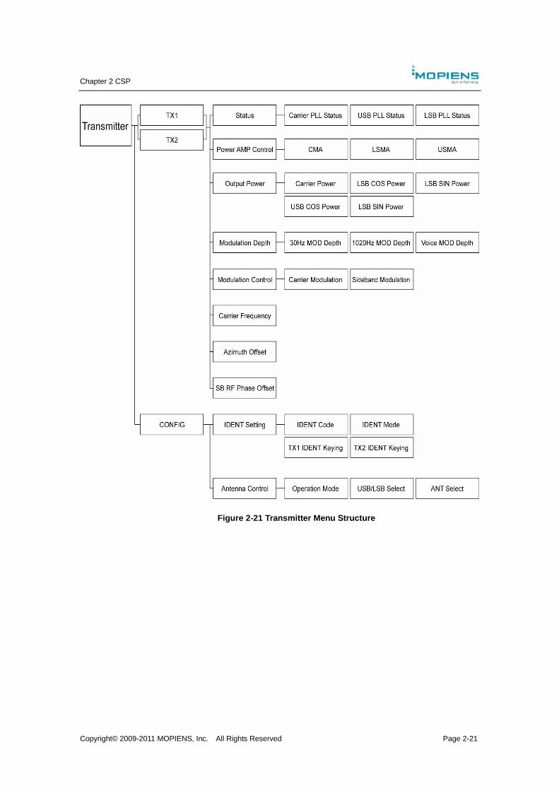
Chapter 2 CSP
Copyright© 2009-2011 MOPIENS, Inc. All Rights Reserved Page 2-21
Figure 2-21 Transmitter Menu Structure
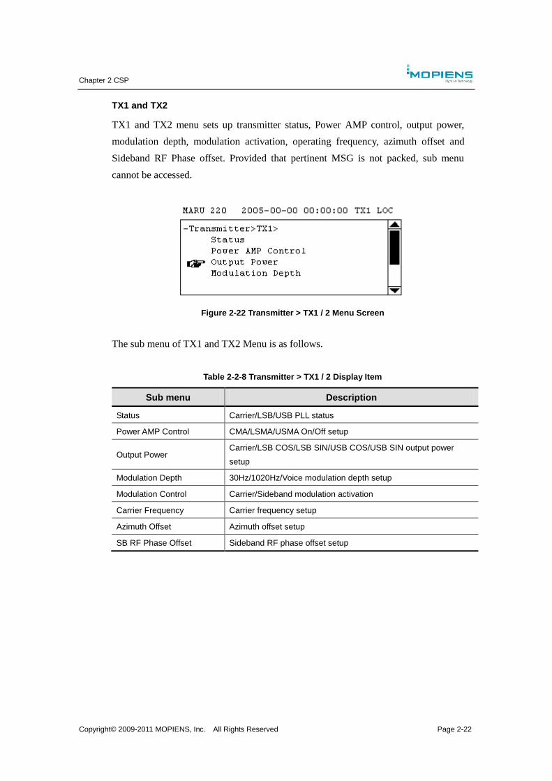
Chapter 2 CSP
Copyright© 2009-2011 MOPIENS, Inc. All Rights Reserved Page 2-22
TX1 and TX2
TX1 and TX2 menu sets up transmitter status, Power AMP control, output power,
modulation depth, modulation activation, operating frequency, azimuth offset and
Sideband RF Phase offset. Provided that pertinent MSG is not packed, sub menu
cannot be accessed.
Figure 2-22 Transmitter > TX1 / 2 Menu Screen
The sub menu of TX1 and TX2 Menu is as follows.
Table 2-2-8 Transmitter > TX1 / 2 Display Item
Sub menu Description
Status Carrier/LSB/USB PLL status
Power AMP Control CMA/LSMA/USMA On/Off setup
Output Power Carrier/LSB COS/LSB SIN/USB COS/USB SIN output power
setup
Modulation Depth 30Hz/1020Hz/Voice modulation depth setup
Modulation Control Carrier/Sideband modulation activation
Carrier Frequency Carrier frequency setup
Azimuth Offset Azimuth offset setup
SB RF Phase Offset Sideband RF phase offset setup
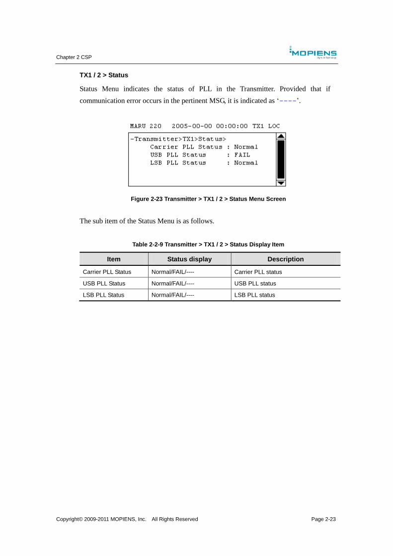
Chapter 2 CSP
Copyright© 2009-2011 MOPIENS, Inc. All Rights Reserved Page 2-23
TX1 / 2 > Status
Status Menu indicates the status of PLL in the Transmitter. Provided that if
communication error occurs in the pertinent MSG, it is indicated as ‘----’.
Figure 2-23 Transmitter > TX1 / 2 > Status Menu Screen
The sub item of the Status Menu is as follows.
Table 2-2-9 Transmitter > TX1 / 2 > Status Display Item
Item Status display Description
Carrier PLL Status Normal/FAIL/---- Carrier PLL status
USB PLL Status Normal/FAIL/---- USB PLL status
LSB PLL Status Normal/FAIL/---- LSB PLL status
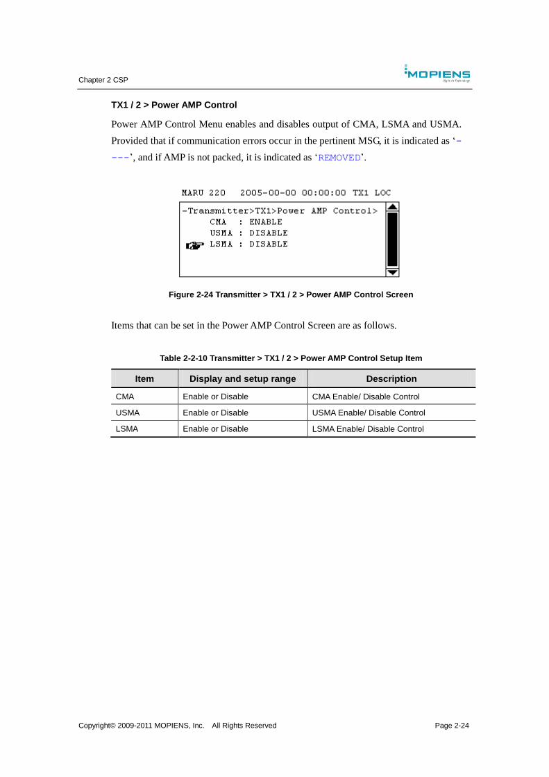
Chapter 2 CSP
Copyright© 2009-2011 MOPIENS, Inc. All Rights Reserved Page 2-24
TX1 / 2 > Power AMP Control
Power AMP Control Menu enables and disables output of CMA, LSMA and USMA.
Provided that if communication errors occur in the pertinent MSG, it is indicated as ‘-
---’, and if AMP is not packed, it is indicated as ‘REMOVED’.
Figure 2-24 Transmitter > TX1 / 2 > Power AMP Control Screen
Items that can be set in the Power AMP Control Screen are as follows.
Table 2-2-10 Transmitter > TX1 / 2 > Power AMP Control Setup Item
Item Display and setup range Description
CMA Enable or Disable CMA Enable/ Disable Control
USMA Enable or Disable USMA Enable/ Disable Control
LSMA Enable or Disable LSMA Enable/ Disable Control
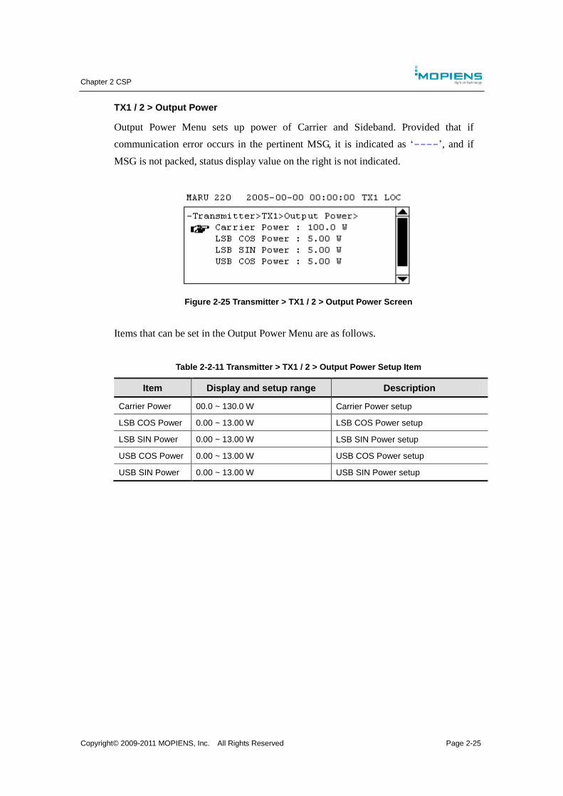
Chapter 2 CSP
Copyright© 2009-2011 MOPIENS, Inc. All Rights Reserved Page 2-25
TX1 / 2 > Output Power
Output Power Menu sets up power of Carrier and Sideband. Provided that if
communication error occurs in the pertinent MSG, it is indicated as ‘----’, and if
MSG is not packed, status display value on the right is not indicated.
Figure 2-25 Transmitter > TX1 / 2 > Output Power Screen
Items that can be set in the Output Power Menu are as follows.
Table 2-2-11 Transmitter > TX1 / 2 > Output Power Setup Item
Item Display and setup range Description
Carrier Power 00.0 ~ 130.0 W Carrier Power setup
LSB COS Power 0.00 ~ 13.00 W LSB COS Power setup
LSB SIN Power 0.00 ~ 13.00 W LSB SIN Power setup
USB COS Power 0.00 ~ 13.00 W USB COS Power setup
USB SIN Power 0.00 ~ 13.00 W USB SIN Power setup
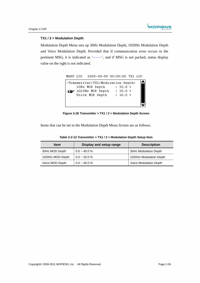
Chapter 2 CSP
Copyright© 2009-2011 MOPIENS, Inc. All Rights Reserved Page 2-26
TX1 / 2 > Modulation Depth
Modulation Depth Menu sets up 30Hz Modulation Depth, 1020Hz Modulation Depth
and Voice Modulation Depth. Provided that if communication error occurs in the
pertinent MSG, it is indicated as ‘----’, and if MSG is not packed, status display
value on the right is not indicated.
Figure 2-26 Transmitter > TX1 / 2 > Modulation Depth Screen
Items that can be set in the Modulation Depth Menu Screen are as follows.
Table 2-2-12 Transmitter > TX1 / 2 > Modulation Depth Setup Item
Item Display and setup range Description
30Hz MOD Depth 0.0 ~ 40.0 % 30Hz Modulation Depth
1020Hz MOD Depth 0.0 ~ 20.0 % 1020Hz Modulation Depth
Voice MOD Depth 0.0 ~ 40.0 % Voice Modulation Depth

Chapter 2 CSP
Copyright© 2009-2011 MOPIENS, Inc. All Rights Reserved Page 2-27
TX1 / 2 > Modulation Control
Modulation Control Menu sets up Carrier and Sideband Modulation On/Off. Provided
that if communication error occurs in the pertinent MSG, it is indicated as ‘----’,
and if MSG is not packed, status display value on the right is not indicated.
Figure 2-27 Transmitter > TX1 / 2 > Modulation Control Screen
Items that can be set up in the Modulation Control Menu Screen are as follows.
Table 2-2-13 Transmitter > TX1 / 2 > Modulation Control Setup Item
Item Display and setup range Description
Carrier Modulation On or Off Carrier Modulation On/Off Control
Sideband Modulation On or Off Sideband Modulation On/Off Control
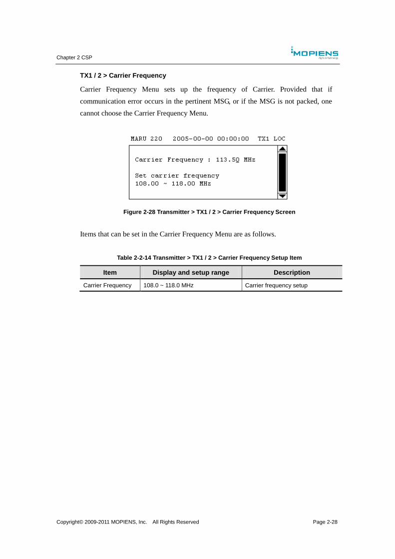
Chapter 2 CSP
Copyright© 2009-2011 MOPIENS, Inc. All Rights Reserved Page 2-28
TX1 / 2 > Carrier Frequency
Carrier Frequency Menu sets up the frequency of Carrier. Provided that if
communication error occurs in the pertinent MSG, or if the MSG is not packed, one
cannot choose the Carrier Frequency Menu.
Figure 2-28 Transmitter > TX1 / 2 > Carrier Frequency Screen
Items that can be set in the Carrier Frequency Menu are as follows.
Table 2-2-14 Transmitter > TX1 / 2 > Carrier Frequency Setup Item
Item Display and setup range Description
Carrier Frequency 108.0 ~ 118.0 MHz Carrier frequency setup
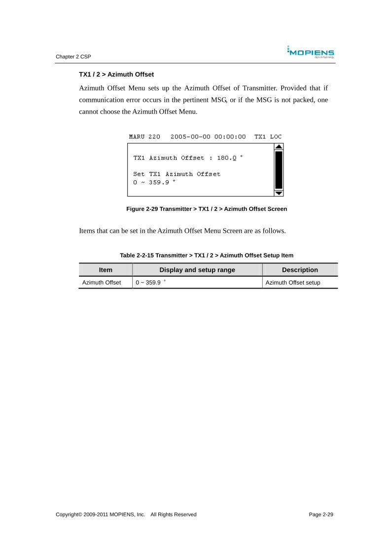
Chapter 2 CSP
Copyright© 2009-2011 MOPIENS, Inc. All Rights Reserved Page 2-29
TX1 / 2 > Azimuth Offset
Azimuth Offset Menu sets up the Azimuth Offset of Transmitter. Provided that if
communication error occurs in the pertinent MSG, or if the MSG is not packed, one
cannot choose the Azimuth Offset Menu.
Figure 2-29 Transmitter > TX1 / 2 > Azimuth Offset Screen
Items that can be set in the Azimuth Offset Menu Screen are as follows.
Table 2-2-15 Transmitter > TX1 / 2 > Azimuth Offset Setup Item
Item Display and setup range Description
Azimuth Offset 0 ~ 359.9 ° Azimuth Offset setup
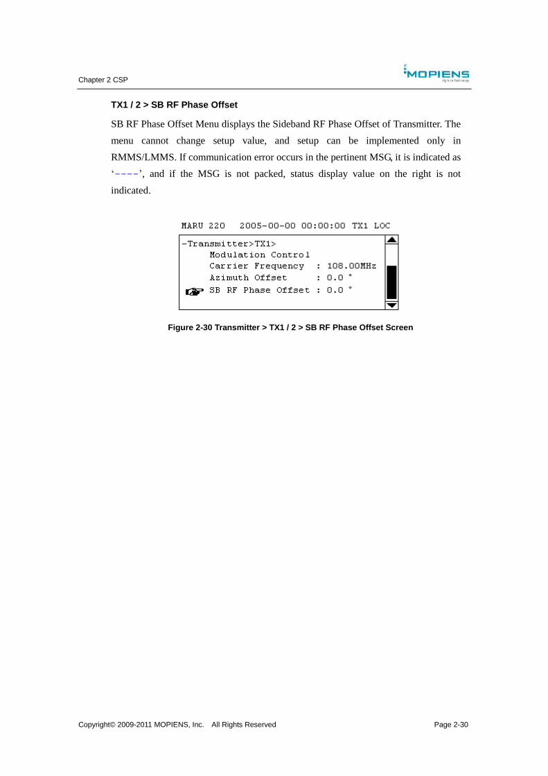
Chapter 2 CSP
Copyright© 2009-2011 MOPIENS, Inc. All Rights Reserved Page 2-30
TX1 / 2 > SB RF Phase Offset
SB RF Phase Offset Menu displays the Sideband RF Phase Offset of Transmitter. The
menu cannot change setup value, and setup can be implemented only in
RMMS/LMMS. If communication error occurs in the pertinent MSG, it is indicated as
‘----’, and if the MSG is not packed, status display value on the right is not
indicated.
Figure 2-30 Transmitter > TX1 / 2 > SB RF Phase Offset Screen
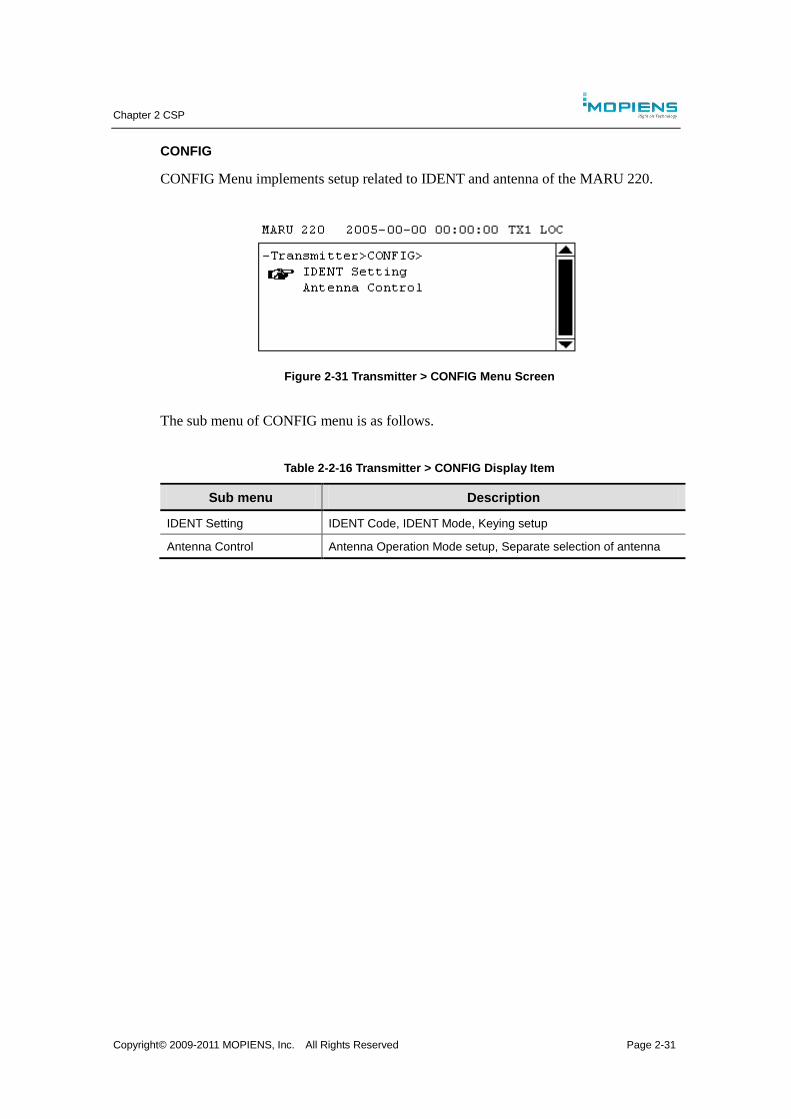
Chapter 2 CSP
Copyright© 2009-2011 MOPIENS, Inc. All Rights Reserved Page 2-31
CONFIG
CONFIG Menu implements setup related to IDENT and antenna of the MARU 220.
Figure 2-31 Transmitter > CONFIG Menu Screen
The sub menu of CONFIG menu is as follows.
Table 2-2-16 Transmitter > CONFIG Display Item
Sub menu Description
IDENT Setting IDENT Code, IDENT Mode, Keying setup
Antenna Control Antenna Operation Mode setup, Separate selection of antenna
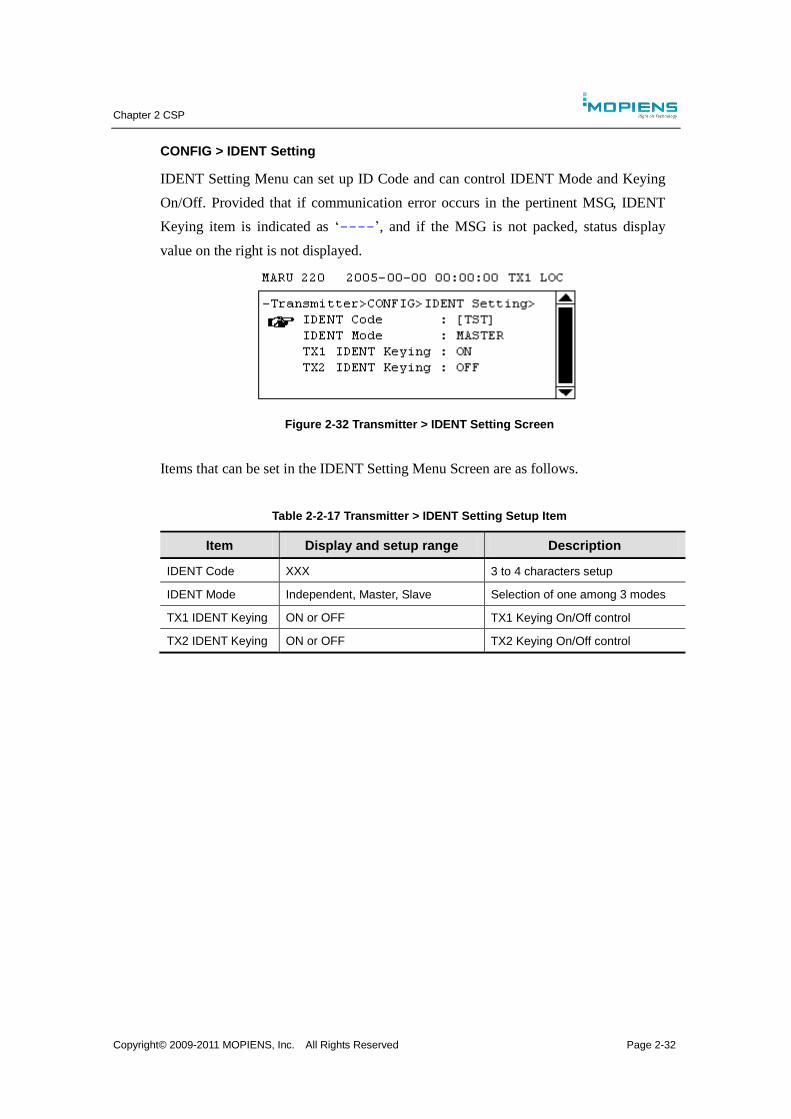
Chapter 2 CSP
Copyright© 2009-2011 MOPIENS, Inc. All Rights Reserved Page 2-32
CONFIG > IDENT Setting
IDENT Setting Menu can set up ID Code and can control IDENT Mode and Keying
On/Off. Provided that if communication error occurs in the pertinent MSG, IDENT
Keying item is indicated as ‘----’, and if the MSG is not packed, status display
value on the right is not displayed.
Figure 2-32 Transmitter > IDENT Setting Screen
Items that can be set in the IDENT Setting Menu Screen are as follows.
Table 2-2-17 Transmitter > IDENT Setting Setup Item
Item Display and setup range Description
IDENT Code XXX 3 to 4 characters setup
IDENT Mode Independent, Master, Slave Selection of one among 3 modes
TX1 IDENT Keying ON or OFF TX1 Keying On/Off control
TX2 IDENT Keying ON or OFF TX2 Keying On/Off control
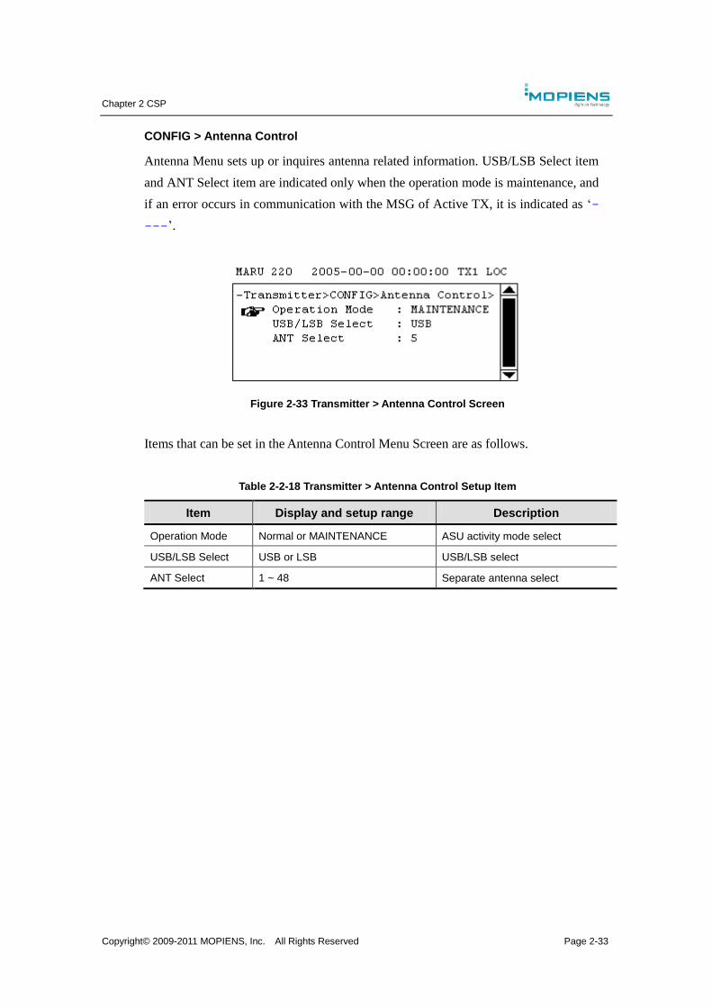
Chapter 2 CSP
Copyright© 2009-2011 MOPIENS, Inc. All Rights Reserved Page 2-33
CONFIG > Antenna Control
Antenna Menu sets up or inquires antenna related information. USB/LSB Select item
and ANT Select item are indicated only when the operation mode is maintenance, and
if an error occurs in communication with the MSG of Active TX, it is indicated as ‘-
---’.
Figure 2-33 Transmitter > Antenna Control Screen
Items that can be set in the Antenna Control Menu Screen are as follows.
Table 2-2-18 Transmitter > Antenna Control Setup Item
Item Display and setup range Description
Operation Mode Normal or MAINTENANCE ASU activity mode select
USB/LSB Select USB or LSB USB/LSB select
ANT Select 1 ~ 48 Separate antenna select
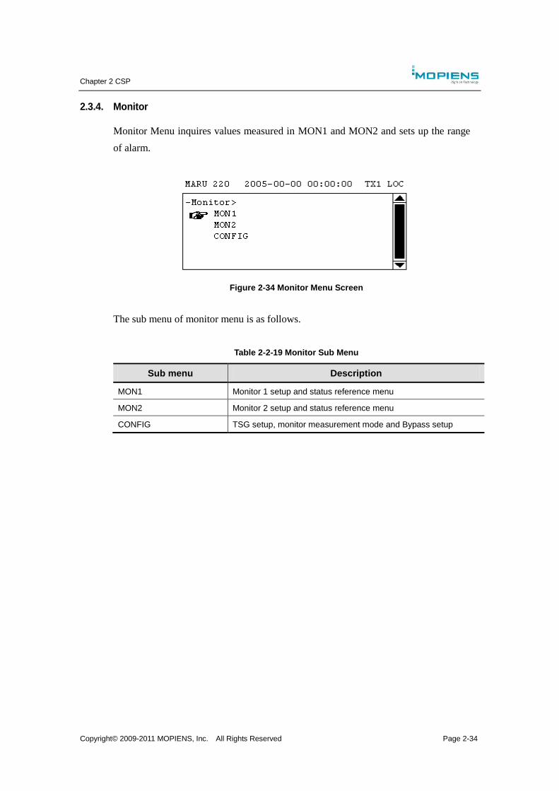
Chapter 2 CSP
Copyright© 2009-2011 MOPIENS, Inc. All Rights Reserved Page 2-34
2.3.4. Monitor
Monitor Menu inquires values measured in MON1 and MON2 and sets up the range
of alarm.
Figure 2-34 Monitor Menu Screen
The sub menu of monitor menu is as follows.
Table 2-2-19 Monitor Sub Menu
Sub menu Description
MON1 Monitor 1 setup and status reference menu
MON2 Monitor 2 setup and status reference menu
CONFIG TSG setup, monitor measurement mode and Bypass setup
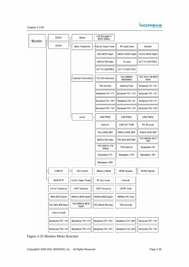
Chapter 2 CSP
Copyright© 2009-2011 MOPIENS, Inc. All Rights Reserved Page 2-35
Figure 2-35 Monitor Menu Structure
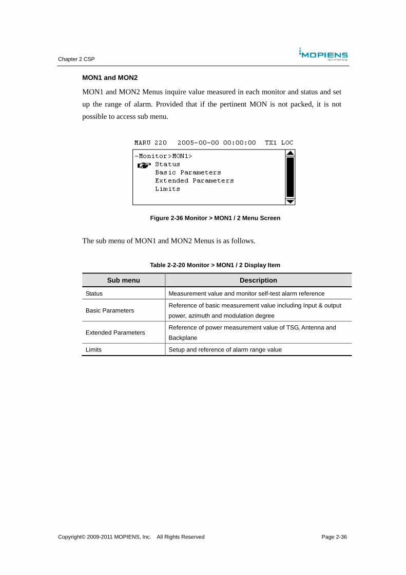
Chapter 2 CSP
Copyright© 2009-2011 MOPIENS, Inc. All Rights Reserved Page 2-36
MON1 and MON2
MON1 and MON2 Menus inquire value measured in each monitor and status and set
up the range of alarm. Provided that if the pertinent MON is not packed, it is not
possible to access sub menu.
Figure 2-36 Monitor > MON1 / 2 Menu Screen
The sub menu of MON1 and MON2 Menus is as follows.
Table 2-2-20 Monitor > MON1 / 2 Display Item
Sub menu Description
Status Measurement value and monitor self-test alarm reference
Basic Parameters Reference of basic measurement value including Input & output
power, azimuth and modulation degree
Extended Parameters Reference of power measurement value of TSG, Antenna and
Backplane
Limits Setup and reference of alarm range value
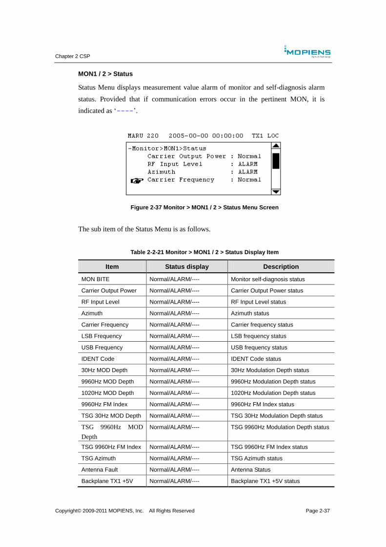
Chapter 2 CSP
Copyright© 2009-2011 MOPIENS, Inc. All Rights Reserved Page 2-37
MON1 / 2 > Status
Status Menu displays measurement value alarm of monitor and self-diagnosis alarm
status. Provided that if communication errors occur in the pertinent MON, it is
indicated as ‘----’.
Figure 2-37 Monitor > MON1 / 2 > Status Menu Screen
The sub item of the Status Menu is as follows.
Table 2-2-21 Monitor > MON1 / 2 > Status Display Item
Item Status display Description
MON BITE Normal/ALARM/---- Monitor self-diagnosis status
Carrier Output Power Normal/ALARM/---- Carrier Output Power status
RF Input Level Normal/ALARM/---- RF Input Level status
Azimuth Normal/ALARM/---- Azimuth status
Carrier Frequency Normal/ALARM/---- Carrier frequency status
LSB Frequency Normal/ALARM/---- LSB frequency status
USB Frequency Normal/ALARM/---- USB frequency status
IDENT Code Normal/ALARM/---- IDENT Code status
30Hz MOD Depth Normal/ALARM/---- 30Hz Modulation Depth status
9960Hz MOD Depth Normal/ALARM/---- 9960Hz Modulation Depth status
1020Hz MOD Depth Normal/ALARM/---- 1020Hz Modulation Depth status
9960Hz FM Index Normal/ALARM/---- 9960Hz FM Index status
TSG 30Hz MOD Depth Normal/ALARM/---- TSG 30Hz Modulation Depth status
TSG 9960Hz MOD
Depth
Normal/ALARM/---- TSG 9960Hz Modulation Depth status
TSG 9960Hz FM Index Normal/ALARM/---- TSG 9960Hz FM Index status
TSG Azimuth Normal/ALARM/---- TSG Azimuth status
Antenna Fault Normal/ALARM/---- Antenna Status
Backplane TX1 +5V Normal/ALARM/---- Backplane TX1 +5V status
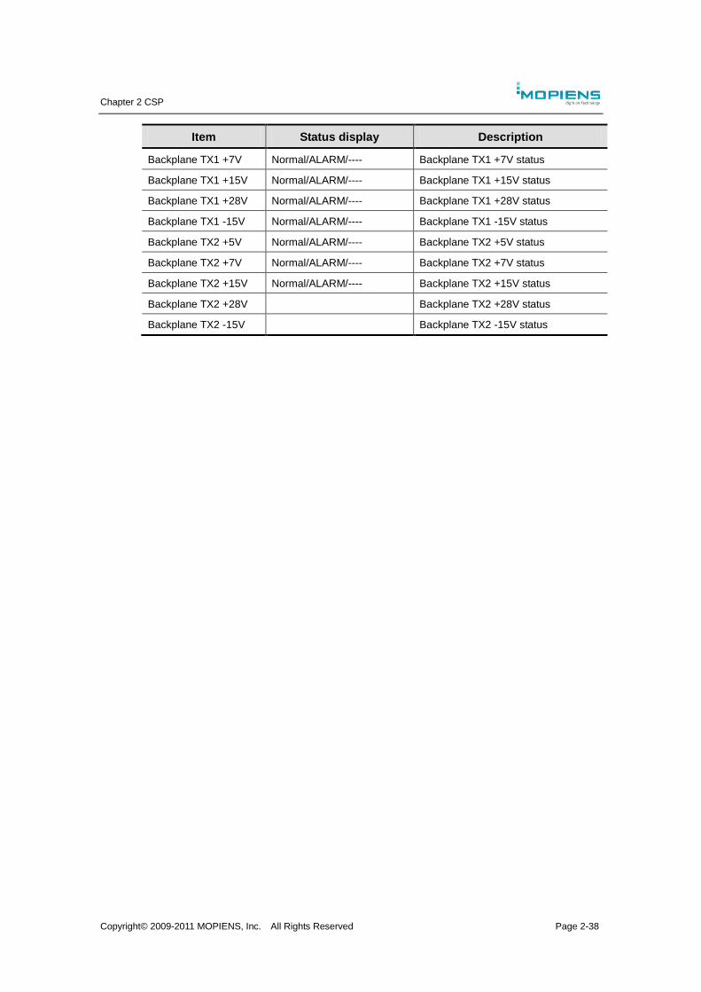
Chapter 2 CSP
Copyright© 2009-2011 MOPIENS, Inc. All Rights Reserved Page 2-38
Item Status display Description
Backplane TX1 +7V Normal/ALARM/---- Backplane TX1 +7V status
Backplane TX1 +15V Normal/ALARM/---- Backplane TX1 +15V status
Backplane TX1 +28V Normal/ALARM/---- Backplane TX1 +28V status
Backplane TX1 -15V Normal/ALARM/---- Backplane TX1 -15V status
Backplane TX2 +5V Normal/ALARM/---- Backplane TX2 +5V status
Backplane TX2 +7V Normal/ALARM/---- Backplane TX2 +7V status
Backplane TX2 +15V Normal/ALARM/---- Backplane TX2 +15V status
Backplane TX2 +28V Backplane TX2 +28V status
Backplane TX2 -15V Backplane TX2 -15V status
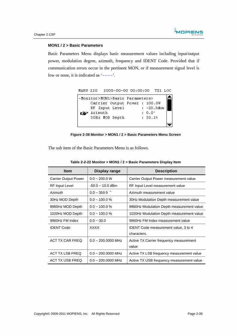
Chapter 2 CSP
Copyright© 2009-2011 MOPIENS, Inc. All Rights Reserved Page 2-39
MON1 / 2 > Basic Parameters
Basic Parameters Menu displays basic measurement values including input/output
power, modulation degree, azimuth, frequency and IDENT Code. Provided that if
communication errors occur in the pertinent MON, or if measurement signal level is
low or none, it is indicated as ‘----’.
Figure 2-38 Monitor > MON1 / 2 > Basic Parameters Menu Screen
The sub item of the Basic Parameters Menu is as follows.
Table 2-2-22 Monitor > MON1 / 2 > Basic Parameters Display Item
Item Display range Description
Carrier Output Power 0.0 ~ 200.0 W Carrier Output Power measurement value
RF Input Level -50.0 ~ 10.0 dBm RF Input Level measurement value
Azimuth 0.0 ~ 359.9 ° Azimuth measurement value
30Hz MOD Depth 0.0 ~ 100.0 % 30Hz Modulation Depth measurement value
9960Hz MOD Depth 0.0 ~ 100.0 % 9960Hz Modulation Depth measurement value
1020Hz MOD Depth 0.0 ~ 100.0 % 1020Hz Modulation Depth measurement value
9960Hz FM Index 0.0 ~ 30.0 9960Hz FM Index measurement value
IDENT Code XXXX IDENT Code measurement value, 3 to 4
characters.
ACT TX CAR FREQ 0.0 ~ 200.0000 MHz Active TX Carrier frequency measurement
value
ACT TX LSB FREQ 0.0 ~ 200.0000 MHz Active TX LSB frequency measurement value
ACT TX USB FREQ 0.0 ~ 200.0000 MHz Active TX USB frequency measurement value
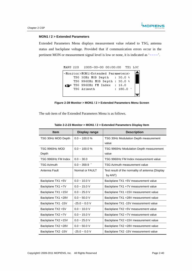
Chapter 2 CSP
Copyright© 2009-2011 MOPIENS, Inc. All Rights Reserved Page 2-40
MON1 / 2 > Extended Parameters
Extended Parameters Menu displays measurement value related to TSG, antenna
status and backplane voltage. Provided that if communication errors occur in the
pertinent MON or measurement signal level is low or none, it is indicated as ‘----’.
Figure 2-39 Monitor > MON1 / 2 > Extended Parameters Menu Screen
The sub item of the Extended Parameters Menu is as follows.
Table 2-2-23 Monitor > MON1 / 2 > Extended Parameters Display Item
Item Display range Description
TSG 30Hz MOD Depth 0.0 ~ 100.0 % TSG 30Hz Modulation Depth measurement
value
TSG 9960Hz MOD
Depth
0.0 ~ 100.0 % TSG 9960Hz Modulation Depth measurement
value
TSG 9960Hz FM Index 0.0 ~ 30.0 TSG 9960Hz FM Index measurement value
TSG Azimuth 0.0 ~ 359.9 ° TSG Azimuth measurement value
Antenna Fault Normal or FAULT Test result of the normality of antenna (Display
by ANT)
Backplane TX1 +5V 0.0 ~ 10.0 V Backplane TX1 +5V measurement value
Backplane TX1 +7V 0.0 ~ 15.0 V Backplane TX1 +7V measurement value
Backplane TX1 +15V 0.0 ~ 25.0 V Backplane TX1 +15V measurement value
Backplane TX1 +28V 0.0 ~ 50.0 V Backplane TX1 +28V measurement value
Backplane TX1 -15V -25.0 ~ 0.0 V Backplane TX1 -15V measurement value
Backplane TX2 +5V 0.0 ~ 10.0 V Backplane TX2 +5V measurement value
Backplane TX2 +7V 0.0 ~ 15.0 V Backplane TX2 +7V measurement value
Backplane TX2 +15V 0.0 ~ 25.0 V Backplane TX2 +15V measurement value
Backplane TX2 +28V 0.0 ~ 50.0 V Backplane TX2 +28V measurement value
Backplane TX2 -15V -25.0 ~ 0.0 V Backplane TX2 -15V measurement value
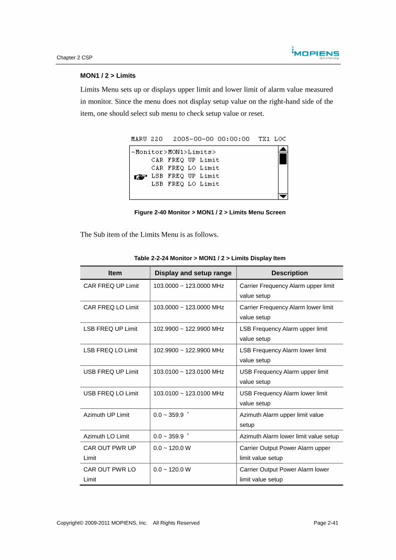
Chapter 2 CSP
Copyright© 2009-2011 MOPIENS, Inc. All Rights Reserved Page 2-41
MON1 / 2 > Limits
Limits Menu sets up or displays upper limit and lower limit of alarm value measured
in monitor. Since the menu does not display setup value on the right-hand side of the
item, one should select sub menu to check setup value or reset.
Figure 2-40 Monitor > MON1 / 2 > Limits Menu Screen
The Sub item of the Limits Menu is as follows.
Table 2-2-24 Monitor > MON1 / 2 > Limits Display Item
Item Display and setup range Description
CAR FREQ UP Limit 103.0000 ~ 123.0000 MHz Carrier Frequency Alarm upper limit
value setup
CAR FREQ LO Limit 103.0000 ~ 123.0000 MHz Carrier Frequency Alarm lower limit
value setup
LSB FREQ UP Limit 102.9900 ~ 122.9900 MHz LSB Frequency Alarm upper limit
value setup
LSB FREQ LO Limit 102.9900 ~ 122.9900 MHz LSB Frequency Alarm lower limit
value setup
USB FREQ UP Limit 103.0100 ~ 123.0100 MHz USB Frequency Alarm upper limit
value setup
USB FREQ LO Limit 103.0100 ~ 123.0100 MHz USB Frequency Alarm lower limit
value setup
Azimuth UP Limit 0.0 ~ 359.9 ° Azimuth Alarm upper limit value
setup
Azimuth LO Limit 0.0 ~ 359.9 ° Azimuth Alarm lower limit value setup
CAR OUT PWR UP
Limit
0.0 ~ 120.0 W Carrier Output Power Alarm upper
limit value setup
CAR OUT PWR LO
Limit
0.0 ~ 120.0 W Carrier Output Power Alarm lower
limit value setup
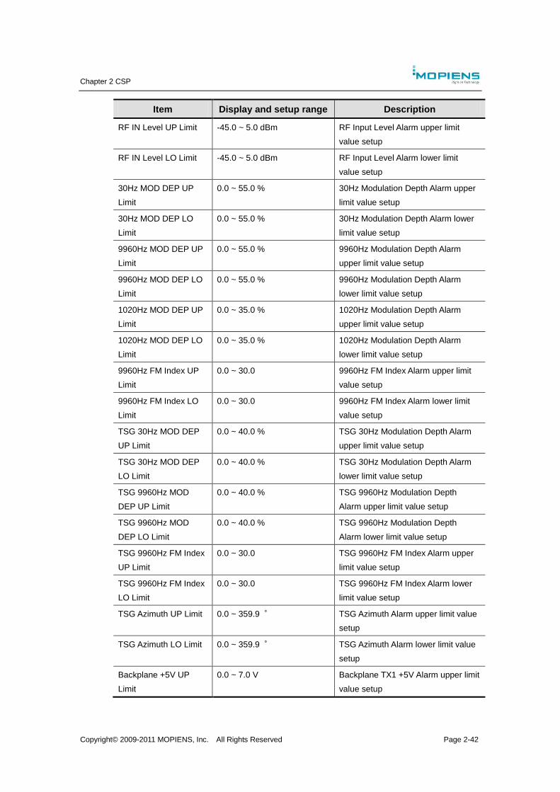
Chapter 2 CSP
Copyright© 2009-2011 MOPIENS, Inc. All Rights Reserved Page 2-42
Item Display and setup range Description
RF IN Level UP Limit -45.0 ~ 5.0 dBm RF Input Level Alarm upper limit
value setup
RF IN Level LO Limit -45.0 ~ 5.0 dBm RF Input Level Alarm lower limit
value setup
30Hz MOD DEP UP
Limit
0.0 ~ 55.0 % 30Hz Modulation Depth Alarm upper
limit value setup
30Hz MOD DEP LO
Limit
0.0 ~ 55.0 % 30Hz Modulation Depth Alarm lower
limit value setup
9960Hz MOD DEP UP
Limit
0.0 ~ 55.0 % 9960Hz Modulation Depth Alarm
upper limit value setup
9960Hz MOD DEP LO
Limit
0.0 ~ 55.0 % 9960Hz Modulation Depth Alarm
lower limit value setup
1020Hz MOD DEP UP
Limit
0.0 ~ 35.0 % 1020Hz Modulation Depth Alarm
upper limit value setup
1020Hz MOD DEP LO
Limit
0.0 ~ 35.0 % 1020Hz Modulation Depth Alarm
lower limit value setup
9960Hz FM Index UP
Limit
0.0 ~ 30.0 9960Hz FM Index Alarm upper limit
value setup
9960Hz FM Index LO
Limit
0.0 ~ 30.0 9960Hz FM Index Alarm lower limit
value setup
TSG 30Hz MOD DEP
UP Limit
0.0 ~ 40.0 % TSG 30Hz Modulation Depth Alarm
upper limit value setup
TSG 30Hz MOD DEP
LO Limit
0.0 ~ 40.0 % TSG 30Hz Modulation Depth Alarm
lower limit value setup
TSG 9960Hz MOD
DEP UP Limit
0.0 ~ 40.0 % TSG 9960Hz Modulation Depth
Alarm upper limit value setup
TSG 9960Hz MOD
DEP LO Limit
0.0 ~ 40.0 % TSG 9960Hz Modulation Depth
Alarm lower limit value setup
TSG 9960Hz FM Index
UP Limit
0.0 ~ 30.0 TSG 9960Hz FM Index Alarm upper
limit value setup
TSG 9960Hz FM Index
LO Limit
0.0 ~ 30.0 TSG 9960Hz FM Index Alarm lower
limit value setup
TSG Azimuth UP Limit 0.0 ~ 359.9 ° TSG Azimuth Alarm upper limit value
setup
TSG Azimuth LO Limit 0.0 ~ 359.9 ° TSG Azimuth Alarm lower limit value
setup
Backplane +5V UP
Limit
0.0 ~ 7.0 V Backplane TX1 +5V Alarm upper limit
value setup
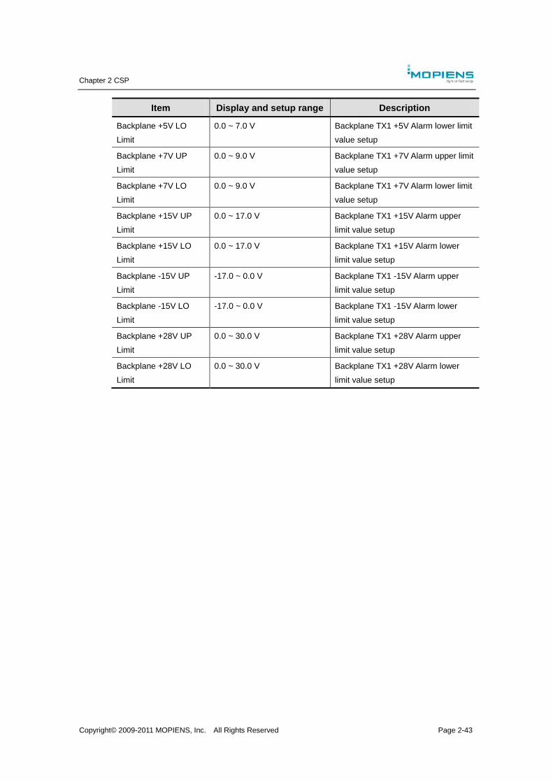
Chapter 2 CSP
Copyright© 2009-2011 MOPIENS, Inc. All Rights Reserved Page 2-43
Item Display and setup range Description
Backplane +5V LO
Limit
0.0 ~ 7.0 V Backplane TX1 +5V Alarm lower limit
value setup
Backplane +7V UP
Limit
0.0 ~ 9.0 V Backplane TX1 +7V Alarm upper limit
value setup
Backplane +7V LO
Limit
0.0 ~ 9.0 V Backplane TX1 +7V Alarm lower limit
value setup
Backplane +15V UP
Limit
0.0 ~ 17.0 V Backplane TX1 +15V Alarm upper
limit value setup
Backplane +15V LO
Limit
0.0 ~ 17.0 V Backplane TX1 +15V Alarm lower
limit value setup
Backplane -15V UP
Limit
-17.0 ~ 0.0 V Backplane TX1 -15V Alarm upper
limit value setup
Backplane -15V LO
Limit
-17.0 ~ 0.0 V Backplane TX1 -15V Alarm lower
limit value setup
Backplane +28V UP
Limit
0.0 ~ 30.0 V Backplane TX1 +28V Alarm upper
limit value setup
Backplane +28V LO
Limit
0.0 ~ 30.0 V Backplane TX1 +28V Alarm lower
limit value setup
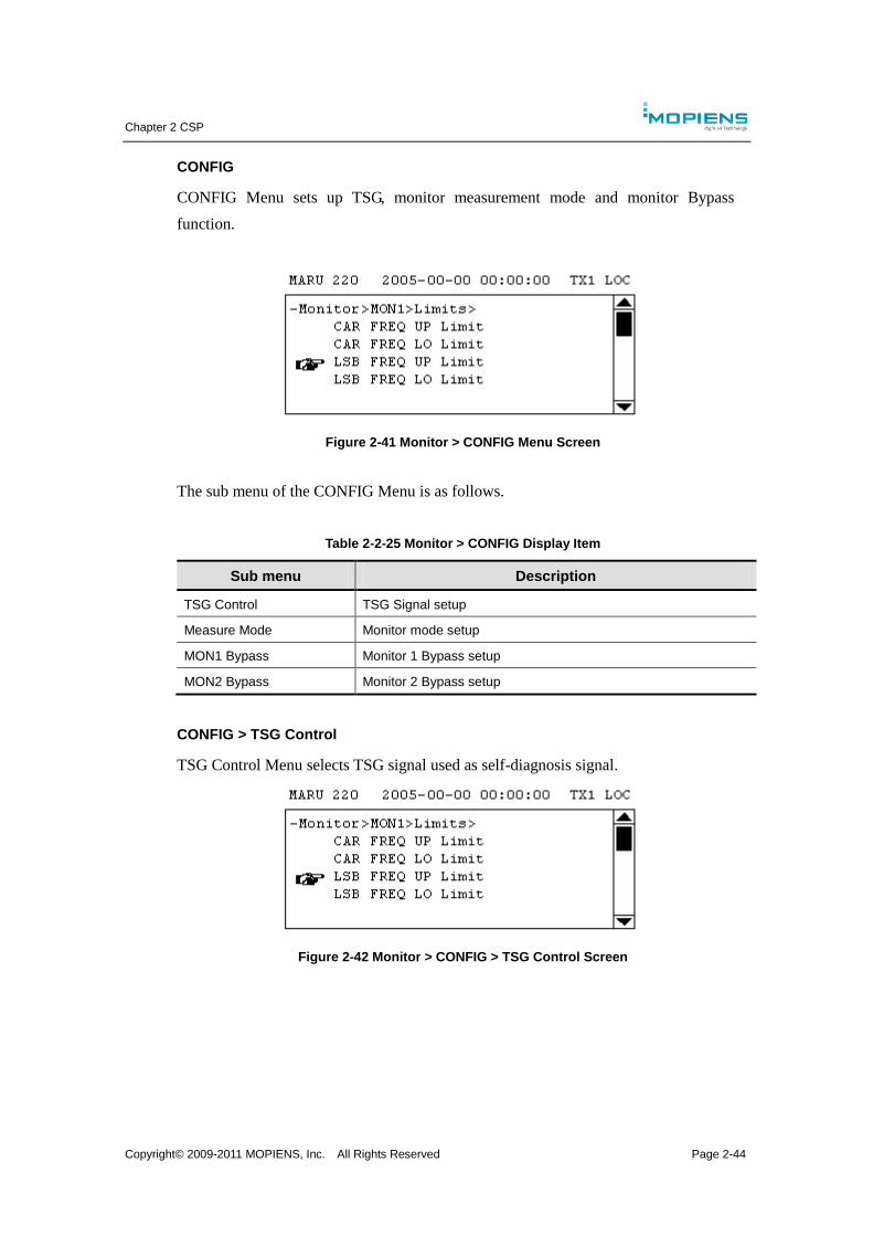
Chapter 2 CSP
Copyright© 2009-2011 MOPIENS, Inc. All Rights Reserved Page 2-44
CONFIG
CONFIG Menu sets up TSG, monitor measurement mode and monitor Bypass
function.
Figure 2-41 Monitor > CONFIG Menu Screen
The sub menu of the CONFIG Menu is as follows.
Table 2-2-25 Monitor > CONFIG Display Item
Sub menu Description
TSG Control TSG Signal setup
Measure Mode Monitor mode setup
MON1 Bypass Monitor 1 Bypass setup
MON2 Bypass Monitor 2 Bypass setup
CONFIG > TSG Control
TSG Control Menu selects TSG signal used as self-diagnosis signal.
Figure 2-42 Monitor > CONFIG > TSG Control Screen
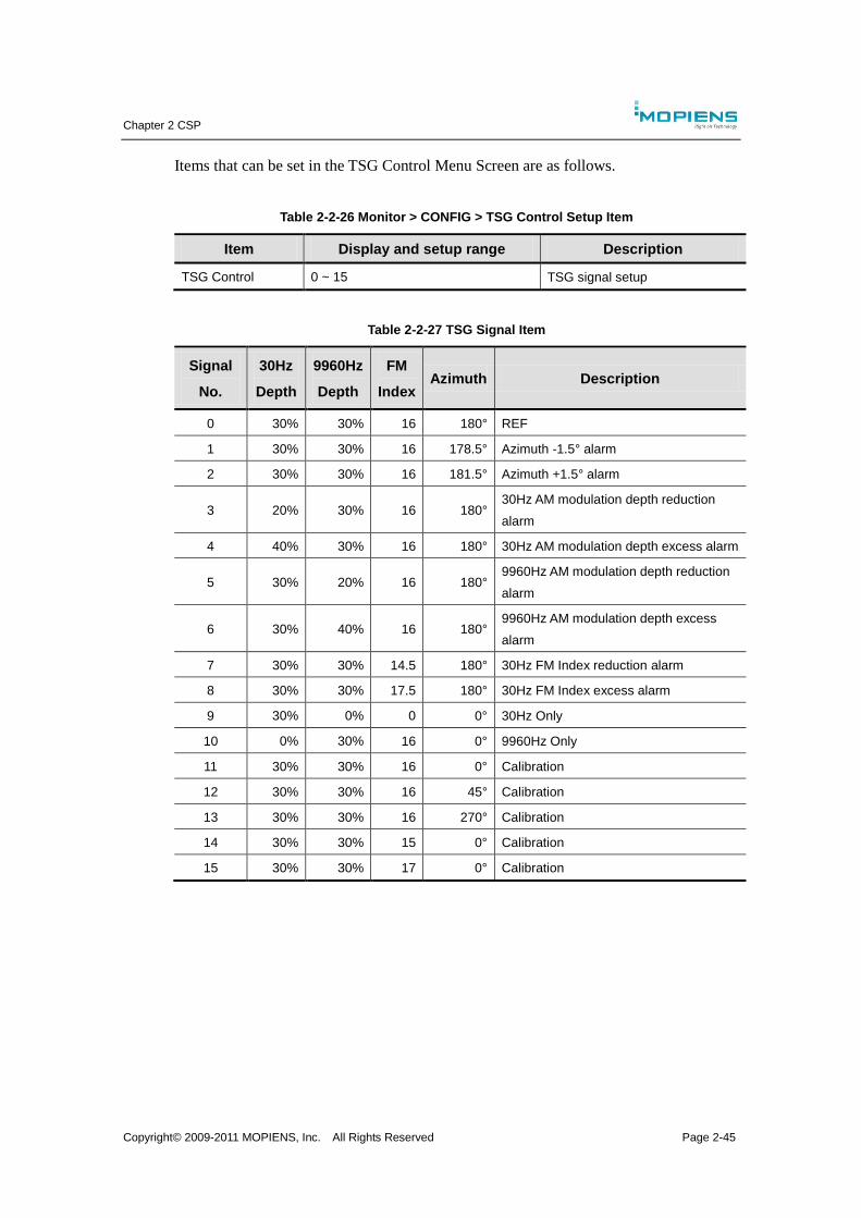
Chapter 2 CSP
Copyright© 2009-2011 MOPIENS, Inc. All Rights Reserved Page 2-45
Items that can be set in the TSG Control Menu Screen are as follows.
Table 2-2-26 Monitor > CONFIG > TSG Control Setup Item
Item Display and setup range Description
TSG Control 0 ~ 15 TSG signal setup
Table 2-2-27 TSG Signal Item
Signal
No.
30Hz
Depth
9960Hz
Depth
FM
Index Azimuth Description
0 30% 30% 16 180° REF
1 30% 30% 16 178.5° Azimuth -1.5° alarm
2 30% 30% 16 181.5° Azimuth +1.5° alarm
3 20% 30% 16 180° 30Hz AM modulation depth reduction
alarm
4 40% 30% 16 180° 30Hz AM modulation depth excess alarm
5 30% 20% 16 180° 9960Hz AM modulation depth reduction
alarm
6 30% 40% 16 180° 9960Hz AM modulation depth excess
alarm
7 30% 30% 14.5 180° 30Hz FM Index reduction alarm
8 30% 30% 17.5 180° 30Hz FM Index excess alarm
9 30% 0% 0 0° 30Hz Only
10 0% 30% 16 0° 9960Hz Only
11 30% 30% 16 0° Calibration
12 30% 30% 16 45° Calibration
13 30% 30% 16 270° Calibration
14 30% 30% 15 0° Calibration
15 30% 30% 17 0° Calibration
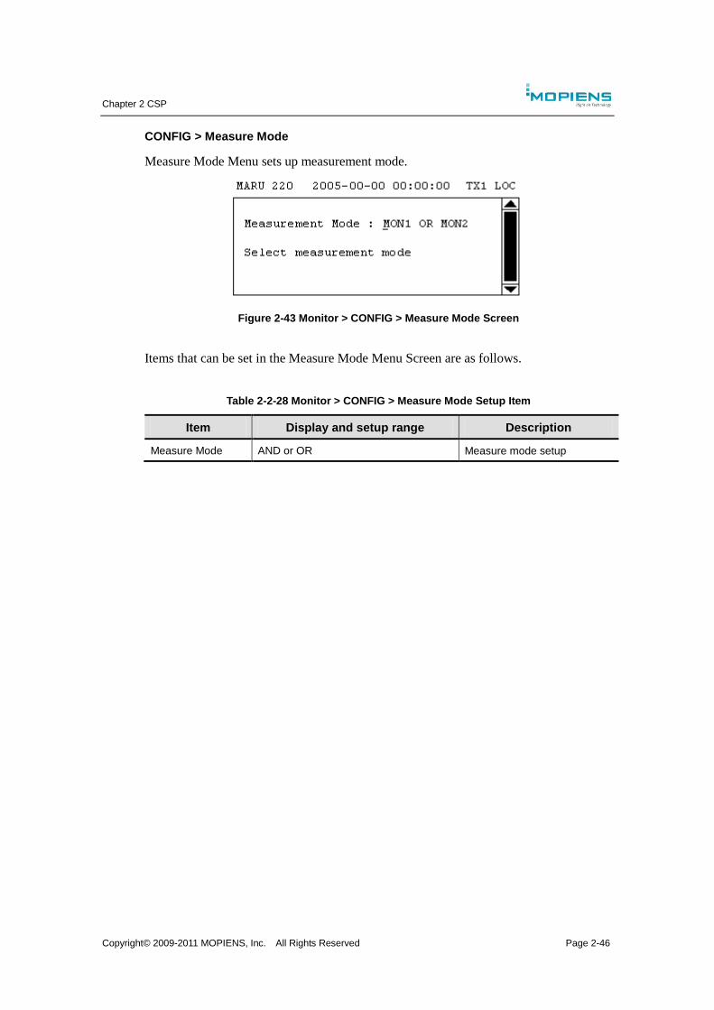
Chapter 2 CSP
Copyright© 2009-2011 MOPIENS, Inc. All Rights Reserved Page 2-46
CONFIG > Measure Mode
Measure Mode Menu sets up measurement mode.
Figure 2-43 Monitor > CONFIG > Measure Mode Screen
Items that can be set in the Measure Mode Menu Screen are as follows.
Table 2-2-28 Monitor > CONFIG > Measure Mode Setup Item
Item Display and setup range Description
Measure Mode AND or OR Measure mode setup
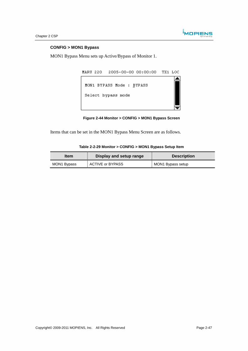
Chapter 2 CSP
Copyright© 2009-2011 MOPIENS, Inc. All Rights Reserved Page 2-47
CONFIG > MON1 Bypass
MON1 Bypass Menu sets up Active/Bypass of Monitor 1.
Figure 2-44 Monitor > CONFIG > MON1 Bypass Screen
Items that can be set in the MON1 Bypass Menu Screen are as follows.
Table 2-2-29 Monitor > CONFIG > MON1 Bypass Setup Item
Item Display and setup range Description
MON1 Bypass ACTIVE or BYPASS MON1 Bypass setup

Chapter 2 CSP
Copyright© 2009-2011 MOPIENS, Inc. All Rights Reserved Page 2-48
CONFIG > MON2 Bypass
MON2 Bypass Menu sets up Active/Bypass of Monitor 2.
MON2 BYPASS Mode : ACTIVE
Select bypass mode
TANS-2000 2005-00-00 00:00:00 TX1 LOC
Figure 2-45 Monitor > CONFIG > MON2 Bypass Screen
Items that can be set in the MON2 Bypass Menu Screen are as follows.
Table 2-2-30 Monitor > CONFIG > MON2 Bypass Setup Item
Item Display and setup range Description
MON2 Bypass ACTIVE or BYPASS MON2 Bypass setup
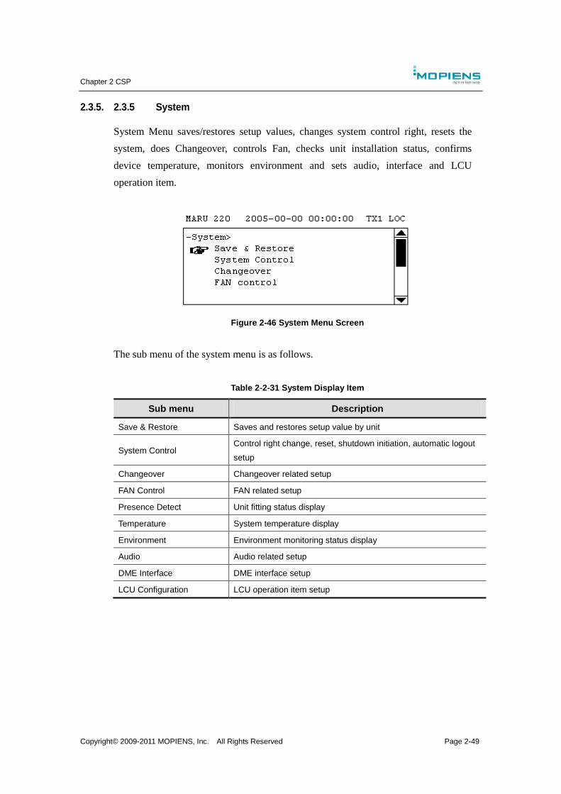
Chapter 2 CSP
Copyright© 2009-2011 MOPIENS, Inc. All Rights Reserved Page 2-49
2.3.5. 2.3.5 System
System Menu saves/restores setup values, changes system control right, resets the
system, does Changeover, controls Fan, checks unit installation status, confirms
device temperature, monitors environment and sets audio, interface and LCU
operation item.
Figure 2-46 System Menu Screen
The sub menu of the system menu is as follows.
Table 2-2-31 System Display Item
Sub menu Description
Save & Restore Saves and restores setup value by unit
System Control Control right change, reset, shutdown initiation, automatic logout
setup
Changeover Changeover related setup
FAN Control FAN related setup
Presence Detect Unit fitting status display
Temperature System temperature display
Environment Environment monitoring status display
Audio Audio related setup
DME Interface DME interface setup
LCU Configuration LCU operation item setup
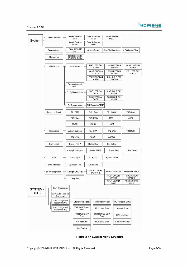
Chapter 2 CSP
Copyright© 2009-2011 MOPIENS, Inc. All Rights Reserved Page 2-50
Figure 2-47 System Menu Structure
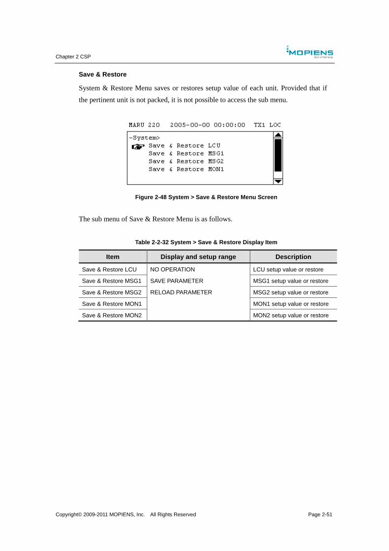
Chapter 2 CSP
Copyright© 2009-2011 MOPIENS, Inc. All Rights Reserved Page 2-51
Save & Restore
System & Restore Menu saves or restores setup value of each unit. Provided that if
the pertinent unit is not packed, it is not possible to access the sub menu.
Figure 2-48 System > Save & Restore Menu Screen
The sub menu of Save & Restore Menu is as follows.
Table 2-2-32 System > Save & Restore Display Item
Item Display and setup range Description
Save & Restore LCU NO OPERATION LCU setup value or restore
Save & Restore MSG1 SAVE PARAMETER MSG1 setup value or restore
Save & Restore MSG2 RELOAD PARAMETER MSG2 setup value or restore
Save & Restore MON1 MON1 setup value or restore
Save & Restore MON2 MON2 setup value or restore
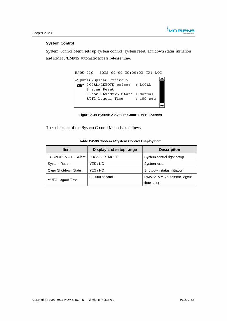
Chapter 2 CSP
Copyright© 2009-2011 MOPIENS, Inc. All Rights Reserved Page 2-52
System Control
System Control Menu sets up system control, system reset, shutdown status initiation
and RMMS/LMMS automatic access release time.
Figure 2-49 System > System Control Menu Screen
The sub menu of the System Control Menu is as follows.
Table 2-2-33 System >System Control Display Item
Item Display and setup range Description
LOCAL/REMOTE Select LOCAL / REMOTE System control right setup
System Reset YES / NO System reset
Clear Shutdown State YES / NO Shutdown status initiation
AUTO Logout Time 0 ~ 600 second RMMS/LMMS automatic logout
time setup
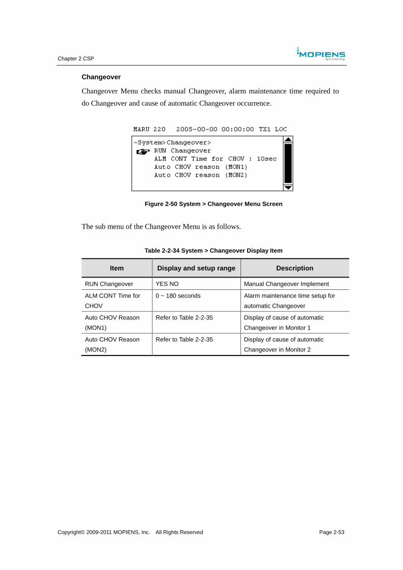
Chapter 2 CSP
Copyright© 2009-2011 MOPIENS, Inc. All Rights Reserved Page 2-53
Changeover
Changeover Menu checks manual Changeover, alarm maintenance time required to
do Changeover and cause of automatic Changeover occurrence.
Figure 2-50 System > Changeover Menu Screen
The sub menu of the Changeover Menu is as follows.
Table 2-2-34 System > Changeover Display Item
Item Display and setup range Description
RUN Changeover YES NO Manual Changeover Implement
ALM CONT Time for
CHOV
0 ~ 180 seconds Alarm maintenance time setup for
automatic Changeover
Auto CHOV Reason
(MON1)
Refer to Table 2-2-35 Display of cause of automatic
Changeover in Monitor 1
Auto CHOV Reason
(MON2)
Refer to Table 2-2-35 Display of cause of automatic
Changeover in Monitor 2
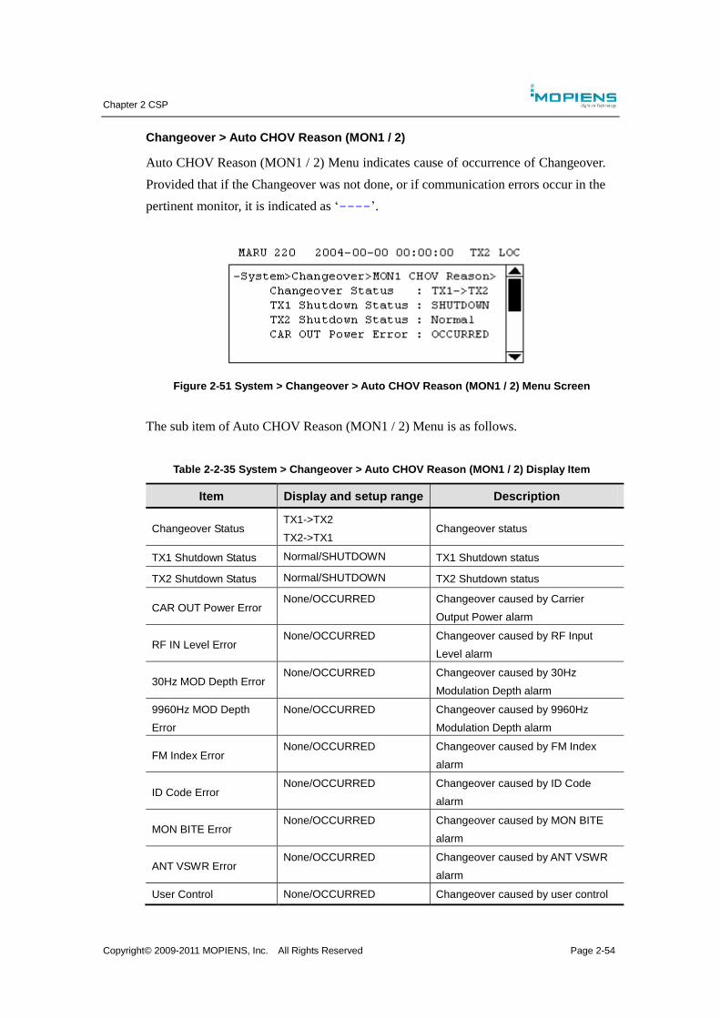
Chapter 2 CSP
Copyright© 2009-2011 MOPIENS, Inc. All Rights Reserved Page 2-54
Changeover > Auto CHOV Reason (MON1 / 2)
Auto CHOV Reason (MON1 / 2) Menu indicates cause of occurrence of Changeover.
Provided that if the Changeover was not done, or if communication errors occur in the
pertinent monitor, it is indicated as ‘----’.
Figure 2-51 System > Changeover > Auto CHOV Reason (MON1 / 2) Menu Screen
The sub item of Auto CHOV Reason (MON1 / 2) Menu is as follows.
Table 2-2-35 System > Changeover > Auto CHOV Reason (MON1 / 2) Display Item
Item Display and setup range Description
Changeover Status TX1->TX2
TX2->TX1 Changeover status
TX1 Shutdown Status Normal/SHUTDOWN TX1 Shutdown status
TX2 Shutdown Status Normal/SHUTDOWN TX2 Shutdown status
CAR OUT Power Error None/OCCURRED Changeover caused by Carrier
Output Power alarm
RF IN Level Error None/OCCURRED Changeover caused by RF Input
Level alarm
30Hz MOD Depth Error None/OCCURRED Changeover caused by 30Hz
Modulation Depth alarm
9960Hz MOD Depth
Error
None/OCCURRED Changeover caused by 9960Hz
Modulation Depth alarm
FM Index Error None/OCCURRED Changeover caused by FM Index
alarm
ID Code Error None/OCCURRED Changeover caused by ID Code
alarm
MON BITE Error None/OCCURRED Changeover caused by MON BITE
alarm
ANT VSWR Error None/OCCURRED Changeover caused by ANT VSWR
alarm
User Control None/OCCURRED Changeover caused by user control
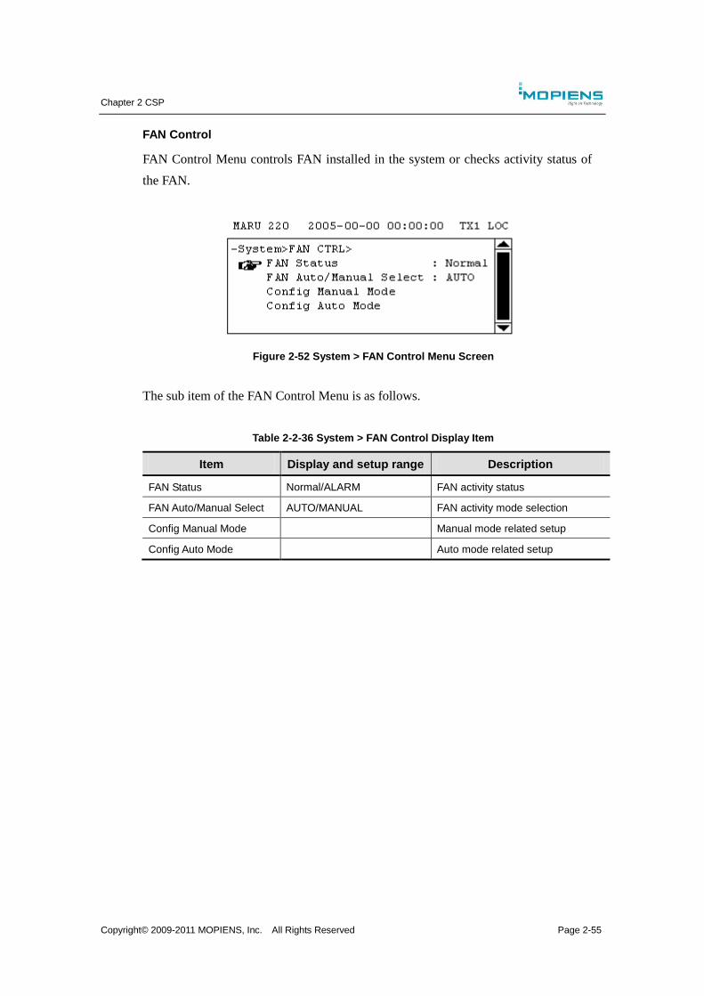
Chapter 2 CSP
Copyright© 2009-2011 MOPIENS, Inc. All Rights Reserved Page 2-55
FAN Control
FAN Control Menu controls FAN installed in the system or checks activity status of
the FAN.
Figure 2-52 System > FAN Control Menu Screen
The sub item of the FAN Control Menu is as follows.
Table 2-2-36 System > FAN Control Display Item
Item Display and setup range Description
FAN Status Normal/ALARM FAN activity status
FAN Auto/Manual Select AUTO/MANUAL FAN activity mode selection
Config Manual Mode Manual mode related setup
Config Auto Mode Auto mode related setup
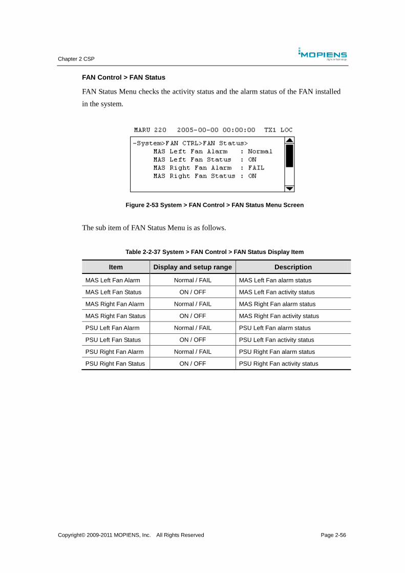
Chapter 2 CSP
Copyright© 2009-2011 MOPIENS, Inc. All Rights Reserved Page 2-56
FAN Control > FAN Status
FAN Status Menu checks the activity status and the alarm status of the FAN installed
in the system.
Figure 2-53 System > FAN Control > FAN Status Menu Screen
The sub item of FAN Status Menu is as follows.
Table 2-2-37 System > FAN Control > FAN Status Display Item
Item Display and setup range Description
MAS Left Fan Alarm Normal / FAIL MAS Left Fan alarm status
MAS Left Fan Status ON / OFF MAS Left Fan activity status
MAS Right Fan Alarm Normal / FAIL MAS Right Fan alarm status
MAS Right Fan Status ON / OFF MAS Right Fan activity status
PSU Left Fan Alarm Normal / FAIL PSU Left Fan alarm status
PSU Left Fan Status ON / OFF PSU Left Fan activity status
PSU Right Fan Alarm Normal / FAIL PSU Right Fan alarm status
PSU Right Fan Status ON / OFF PSU Right Fan activity status
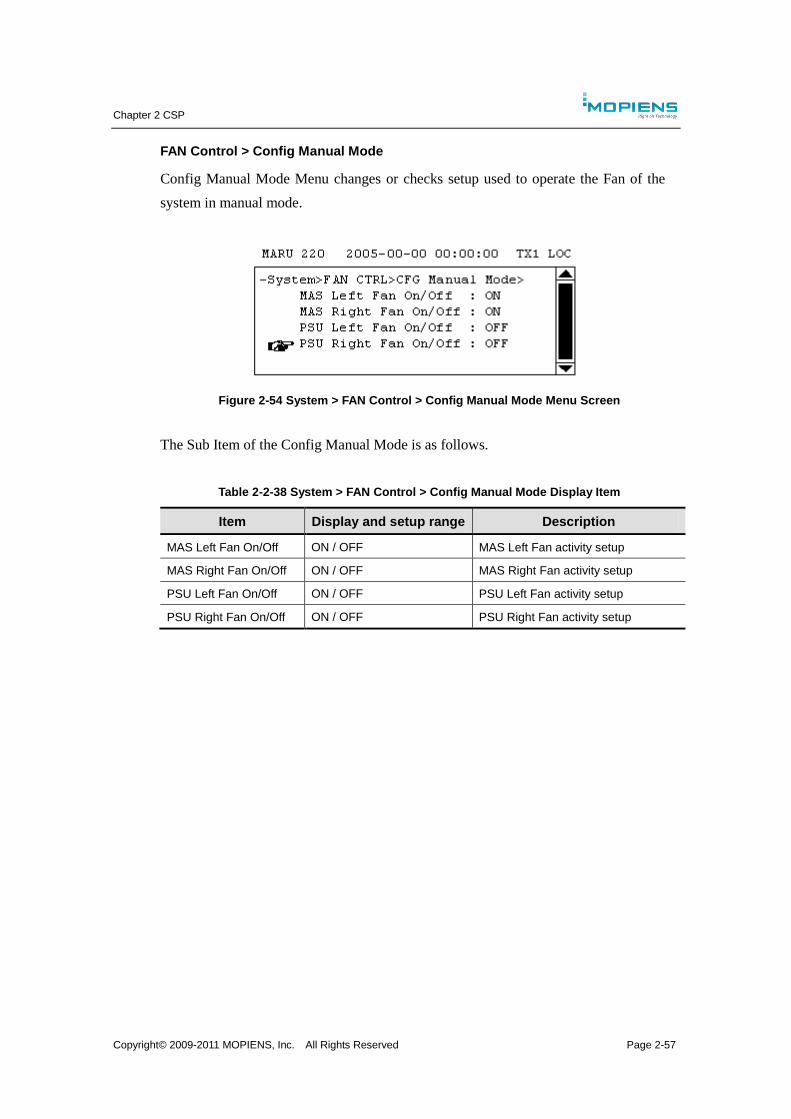
Chapter 2 CSP
Copyright© 2009-2011 MOPIENS, Inc. All Rights Reserved Page 2-57
FAN Control > Config Manual Mode
Config Manual Mode Menu changes or checks setup used to operate the Fan of the
system in manual mode.
Figure 2-54 System > FAN Control > Config Manual Mode Menu Screen
The Sub Item of the Config Manual Mode is as follows.
Table 2-2-38 System > FAN Control > Config Manual Mode Display Item
Item Display and setup range Description
MAS Left Fan On/Off ON / OFF MAS Left Fan activity setup
MAS Right Fan On/Off ON / OFF MAS Right Fan activity setup
PSU Left Fan On/Off ON / OFF PSU Left Fan activity setup
PSU Right Fan On/Off ON / OFF PSU Right Fan activity setup

Chapter 2 CSP
Copyright© 2009-2011 MOPIENS, Inc. All Rights Reserved Page 2-58
FAN Control > Config Auto Mode
Config Auto Mode Menu changes or confirms setup used to operate the FAN of the
System in Auto mode.
Figure 2-55 System > FAN Control > Config Auto Mode Menu Screen
The sub item of the Config Auto Mode Menu is as follows.
Table 2-2-39 System > FAN Control > Config Auto Mode Display Item
Item Display and setup range Description
Fan Operation TEMP -55.0 ~ 125.0 ℃ Fan activity temperature setup
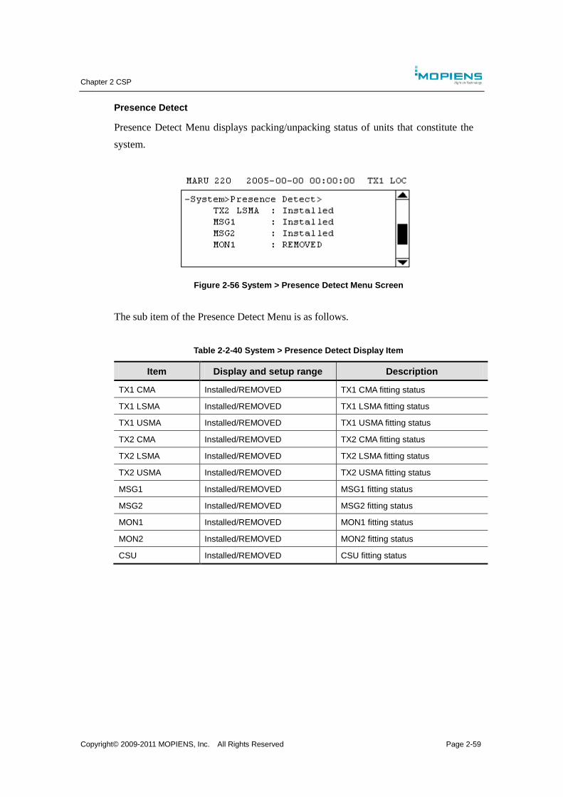
Chapter 2 CSP
Copyright© 2009-2011 MOPIENS, Inc. All Rights Reserved Page 2-59
Presence Detect
Presence Detect Menu displays packing/unpacking status of units that constitute the
system.
Figure 2-56 System > Presence Detect Menu Screen
The sub item of the Presence Detect Menu is as follows.
Table 2-2-40 System > Presence Detect Display Item
Item Display and setup range Description
TX1 CMA Installed/REMOVED TX1 CMA fitting status
TX1 LSMA Installed/REMOVED TX1 LSMA fitting status
TX1 USMA Installed/REMOVED TX1 USMA fitting status
TX2 CMA Installed/REMOVED TX2 CMA fitting status
TX2 LSMA Installed/REMOVED TX2 LSMA fitting status
TX2 USMA Installed/REMOVED TX2 USMA fitting status
MSG1 Installed/REMOVED MSG1 fitting status
MSG2 Installed/REMOVED MSG2 fitting status
MON1 Installed/REMOVED MON1 fitting status
MON2 Installed/REMOVED MON2 fitting status
CSU Installed/REMOVED CSU fitting status
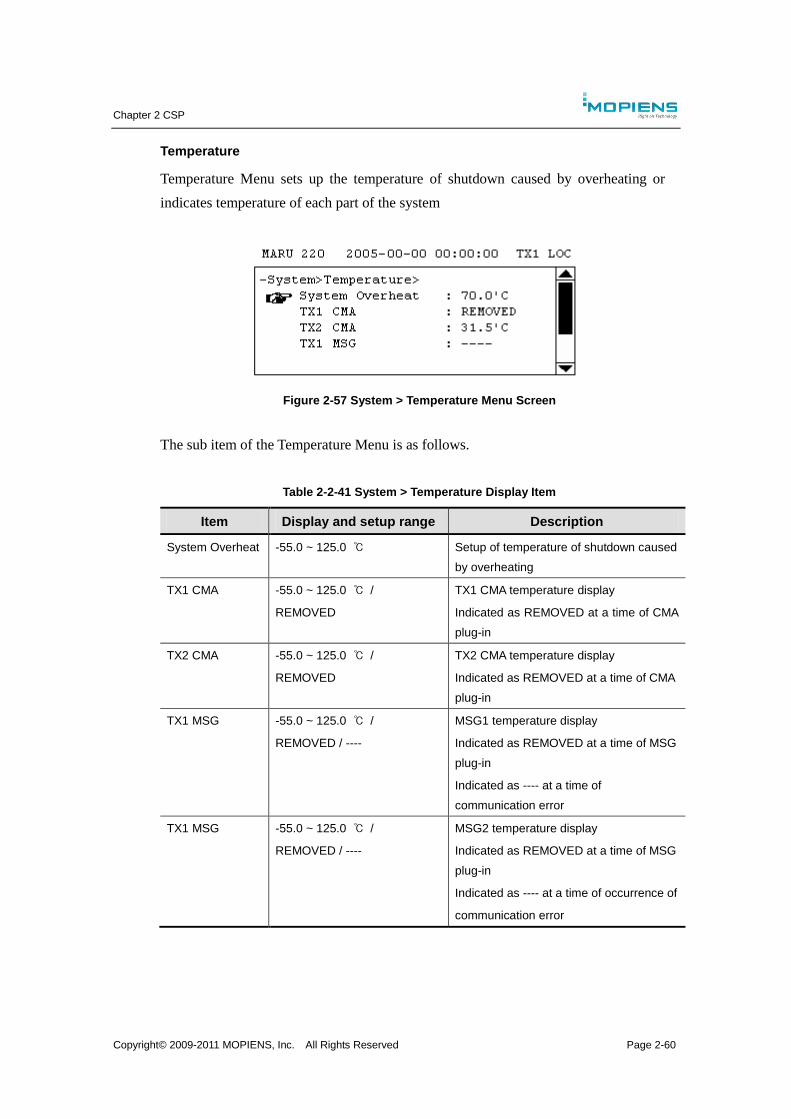
Chapter 2 CSP
Copyright© 2009-2011 MOPIENS, Inc. All Rights Reserved Page 2-60
Temperature
Temperature Menu sets up the temperature of shutdown caused by overheating or
indicates temperature of each part of the system
Figure 2-57 System > Temperature Menu Screen
The sub item of the Temperature Menu is as follows.
Table 2-2-41 System > Temperature Display Item
Item Display and setup range Description
System Overheat -55.0 ~ 125.0 ℃ Setup of temperature of shutdown caused
by overheating
TX1 CMA -55.0 ~ 125.0 ℃ /
REMOVED
TX1 CMA temperature display
Indicated as REMOVED at a time of CMA
plug-in
TX2 CMA -55.0 ~ 125.0 ℃ /
REMOVED
TX2 CMA temperature display
Indicated as REMOVED at a time of CMA
plug-in
TX1 MSG -55.0 ~ 125.0 ℃ /
REMOVED / ----
MSG1 temperature display
Indicated as REMOVED at a time of MSG
plug-in
Indicated as ---- at a time of
communication error
TX1 MSG -55.0 ~ 125.0 ℃ /
REMOVED / ----
MSG2 temperature display
Indicated as REMOVED at a time of MSG
plug-in
Indicated as ---- at a time of occurrence of
communication error
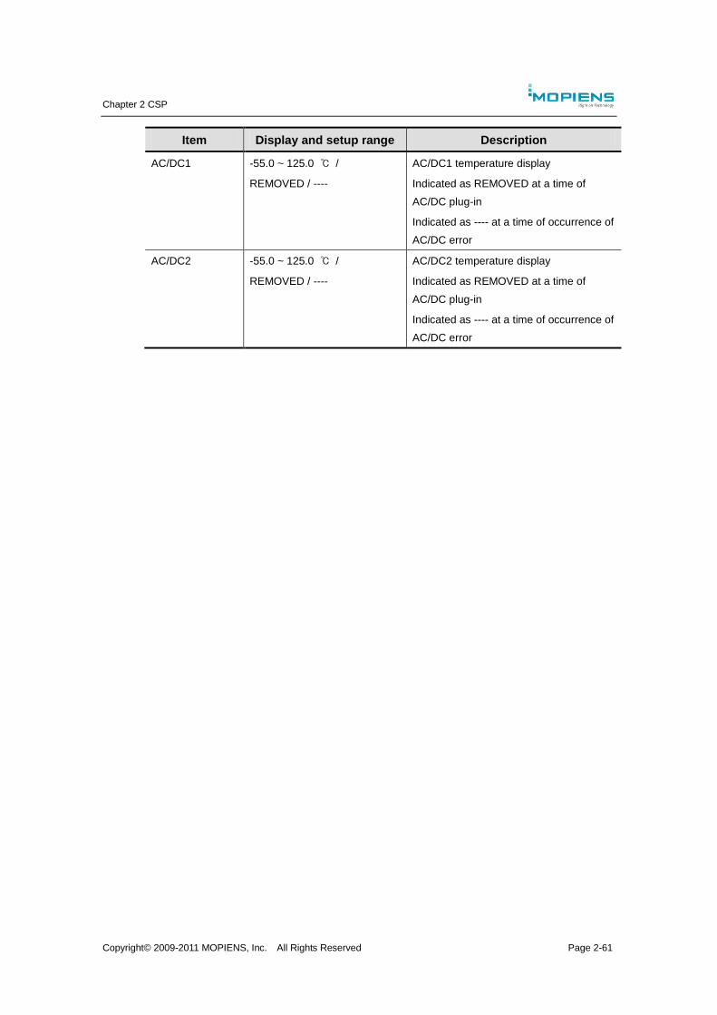
Chapter 2 CSP
Copyright© 2009-2011 MOPIENS, Inc. All Rights Reserved Page 2-61
Item Display and setup range Description
AC/DC1 -55.0 ~ 125.0 ℃ /
REMOVED / ----
AC/DC1 temperature display
Indicated as REMOVED at a time of
AC/DC plug-in
Indicated as ---- at a time of occurrence of
AC/DC error
AC/DC2 -55.0 ~ 125.0 ℃ /
REMOVED / ----
AC/DC2 temperature display
Indicated as REMOVED at a time of
AC/DC plug-in
Indicated as ---- at a time of occurrence of
AC/DC error
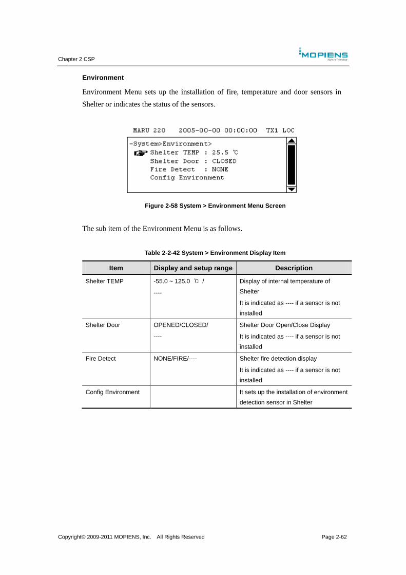
Chapter 2 CSP
Copyright© 2009-2011 MOPIENS, Inc. All Rights Reserved Page 2-62
Environment
Environment Menu sets up the installation of fire, temperature and door sensors in
Shelter or indicates the status of the sensors.
Figure 2-58 System > Environment Menu Screen
The sub item of the Environment Menu is as follows.
Table 2-2-42 System > Environment Display Item
Item Display and setup range Description
Shelter TEMP -55.0 ~ 125.0 ℃ /
----
Display of internal temperature of
Shelter
It is indicated as ---- if a sensor is not
installed
Shelter Door OPENED/CLOSED/
----
Shelter Door Open/Close Display
It is indicated as ---- if a sensor is not
installed
Fire Detect NONE/FIRE/---- Shelter fire detection display
It is indicated as ---- if a sensor is not
installed
Config Environment It sets up the installation of environment
detection sensor in Shelter

Chapter 2 CSP
Copyright© 2009-2011 MOPIENS, Inc. All Rights Reserved Page 2-63
Environment > Config Environment
Config Environment Menu sets up the installation of fire, temperature, door sensors
in Shelter
Figure 2-59 System > Environment > Config Environment Menu Screen
The sub item of the Config Environment Menu is as follows.
Table 2-2-43 System > Environment > Config Environment Display Item
Item Display and setup range Description
TEMP Sensor NONE/INSTALLED It sets up the installation of temperature
sensor inside Shelter
Door Sensor NONE/INSTALLED It sets up the installation of Shelter Door
sensor
Fire Sensor NONE/INSTALLED It sets up the installation of fire monitoring
sensor of Shelter
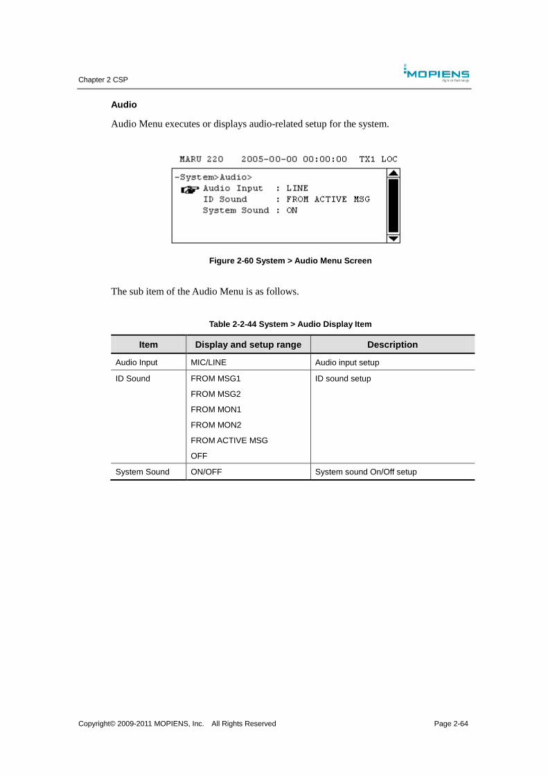
Chapter 2 CSP
Copyright© 2009-2011 MOPIENS, Inc. All Rights Reserved Page 2-64
Audio
Audio Menu executes or displays audio-related setup for the system.
Figure 2-60 System > Audio Menu Screen
The sub item of the Audio Menu is as follows.
Table 2-2-44 System > Audio Display Item
Item Display and setup range Description
Audio Input MIC/LINE Audio input setup
ID Sound FROM MSG1
FROM MSG2
FROM MON1
FROM MON2
FROM ACTIVE MSG
OFF
ID sound setup
System Sound ON/OFF System sound On/Off setup
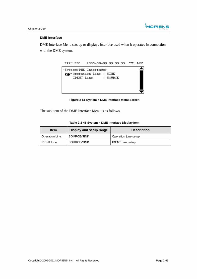
Chapter 2 CSP
Copyright© 2009-2011 MOPIENS, Inc. All Rights Reserved Page 2-65
DME Interface
DME Interface Menu sets up or displays interface used when it operates in connection
with the DME system.
Figure 2-61 System > DME Interface Menu Screen
The sub item of the DME Interface Menu is as follows.
Table 2-2-45 System > DME Interface Display Item
Item Display and setup range Description
Operation Line SOURCE/SINK Operation Line setup
IDENT Line SOURCE/SINK IDENT Line setup
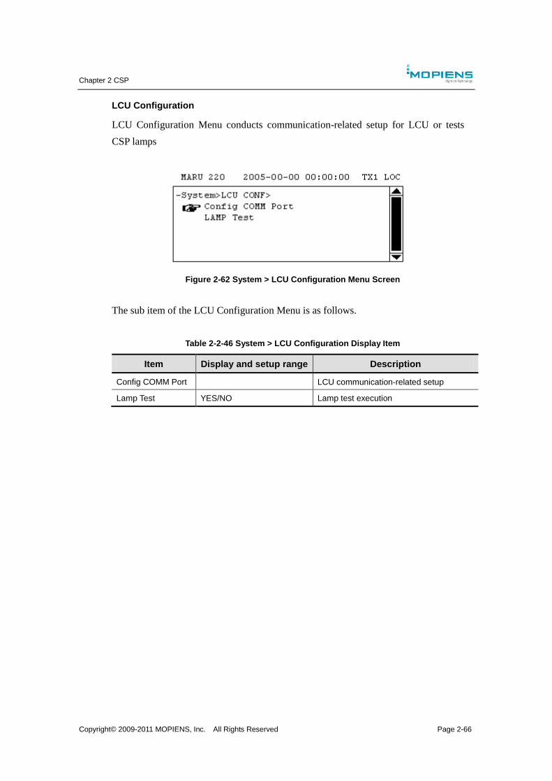
Chapter 2 CSP
Copyright© 2009-2011 MOPIENS, Inc. All Rights Reserved Page 2-66
LCU Configuration
LCU Configuration Menu conducts communication-related setup for LCU or tests
CSP lamps
Figure 2-62 System > LCU Configuration Menu Screen
The sub item of the LCU Configuration Menu is as follows.
Table 2-2-46 System > LCU Configuration Display Item
Item Display and setup range Description
Config COMM Port LCU communication-related setup
Lamp Test YES/NO Lamp test execution
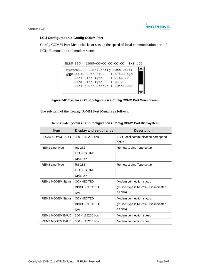
Chapter 2 CSP
Copyright© 2009-2011 MOPIENS, Inc. All Rights Reserved Page 2-67
LCU Configuration > Config COMM Port
Config COMM Port Menu checks or sets up the speed of local communication port of
LCU, Remote line and modem status.
Figure 2-63 System > LCU Configuration > Config COMM Port Menu Screen
The sub item of the Config COMM Port Menu is as follows.
Table 2-2-47 System > LCU Configuration > Config COMM Port Display Item
Item Display and setup range Description
LOCAL COMM BAUD 300 ~ 115200 bps LCU Local communication port speed
setup
REM1 Line Type RS-232
LEASED LINE
DIAL-UP
Remote 1 Line Type setup
REM2 Line Type RS-232
LEASED LINE
DIAL-UP
Remote 2 Line Type setup
REM1 MODEM Status CONNECTED
DISCONNECTED
N/A
Modem connection status
(If Line Type is RS-232, it is indicated
as N/A)
REM2 MODEM Status CONNECTED
DISCONNECTED
N/A
Modem connection status
(If Line Type is RS-232, it is indicated
as N/A)
REM1 MODEM BAUD 300 ~ 115200 bps Modem connection speed
REM2 MODEM BAUD 300 ~ 115200 bps Modem connection speed

Chapter 2 CSP
Copyright© 2009-2011 MOPIENS, Inc. All Rights Reserved Page 2-68
2.3.6. Power Supply
Power Supply Menu displays the status of each PSU unit and output voltage/ current.
Figure 2-64 Power Supply Menu Screen
The sub menu of the Power Supply Menu is as follows.
Table 2-2-48 Power Supply Display Item
Sub menu Description
PSU Status AC/DC, DC/DC, battery status display, outage status display
PSU Measurement AC/DC, DC/DC, battery voltage/current measurement value
display
Figure 2-65 Power Supply Menu Structure
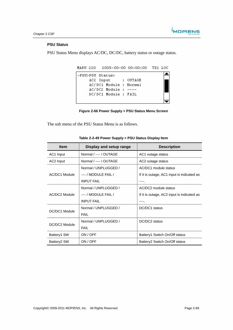
Chapter 2 CSP
Copyright© 2009-2011 MOPIENS, Inc. All Rights Reserved Page 2-69
PSU Status
PSU Status Menu displays AC/DC, DC/DC, battery status or outage status.
Figure 2-66 Power Supply > PSU Status Menu Screen
The sub menu of the PSU Status Menu is as follows.
Table 2-2-49 Power Supply > PSU Status Display Item
Item Display and setup range Description
AC1 Input Normal / ---- / OUTAGE AC1 outage status
AC2 Input Normal / ---- / OUTAGE AC2 outage status
AC/DC1 Module
Normal / UNPLUGGED /
---- / MODULE FAIL /
INPUT FAIL
AC/DC1 module status
If it is outage, AC1 input is indicated as
----.
AC/DC2 Module
Normal / UNPLUGGED /
---- / MODULE FAIL /
INPUT FAIL
AC/DC2 module status
If it is outage, AC2 input is indicated as
----.
DC/DC1 Module Normal / UNPLUGGED /
FAIL
DC/DC1 status
DC/DC2 Module Normal / UNPLUGGED /
FAIL
DC/DC2 status
Battery1 SW ON / OFF Battery1 Switch On/Off status
Battery2 SW ON / OFF Battery2 Switch On/Off status
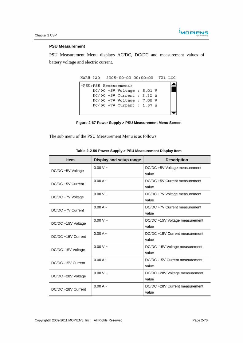
Chapter 2 CSP
Copyright© 2009-2011 MOPIENS, Inc. All Rights Reserved Page 2-70
PSU Measurement
PSU Measurement Menu displays AC/DC, DC/DC and measurement values of
battery voltage and electric current.
Figure 2-67 Power Supply > PSU Measurement Menu Screen
The sub menu of the PSU Measurement Menu is as follows.
Table 2-2-50 Power Supply > PSU Measurement Display Item
Item Display and setup range Description
DC/DC +5V Voltage 0.00 V ~ DC/DC +5V Voltage measurement
value
DC/DC +5V Current 0.00 A ~ DC/DC +5V Current measurement
value
DC/DC +7V Voltage 0.00 V ~ DC/DC +7V Voltage measurement
value
DC/DC +7V Current 0.00 A ~ DC/DC +7V Current measurement
value
DC/DC +15V Voltage 0.00 V ~ DC/DC +15V Voltage measurement
value
DC/DC +15V Current 0.00 A ~ DC/DC +15V Current measurement
value
DC/DC -15V Voltage 0.00 V ~ DC/DC -15V Voltage measurement
value
DC/DC -15V Current 0.00 A ~ DC/DC -15V Current measurement
value
DC/DC +28V Voltage 0.00 V ~ DC/DC +28V Voltage measurement
value
DC/DC +28V Current 0.00 A ~ DC/DC +28V Current measurement
value
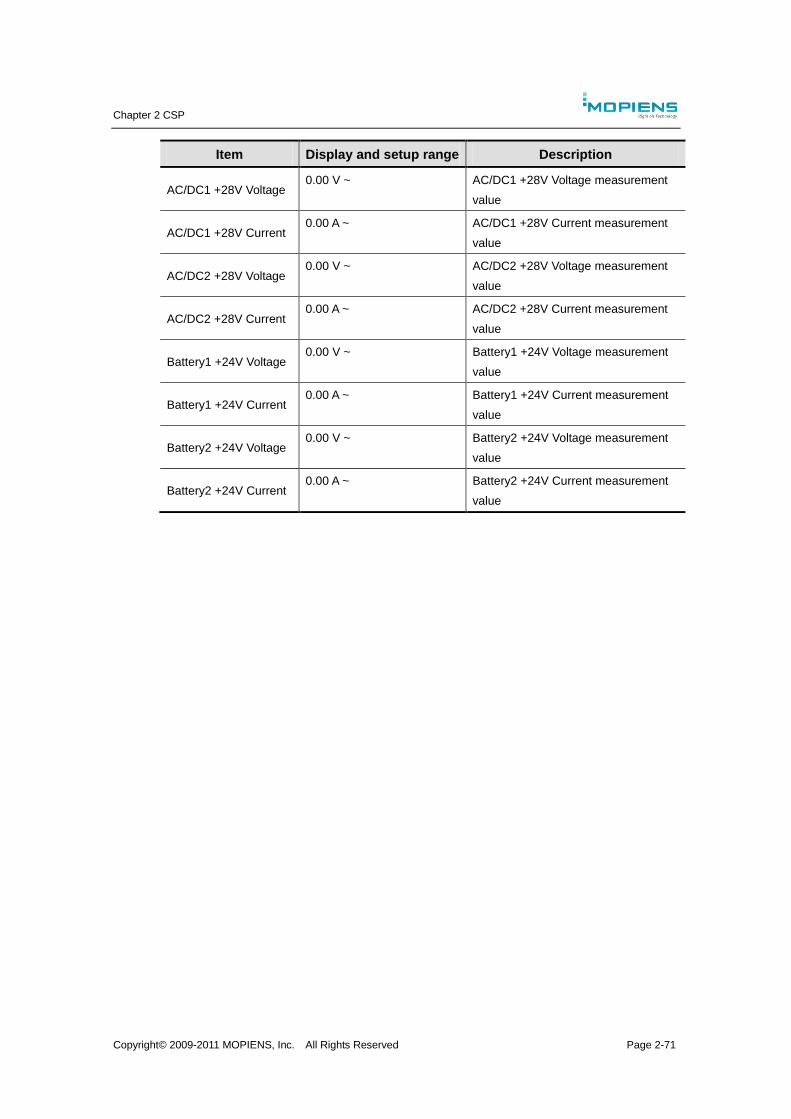
Chapter 2 CSP
Copyright© 2009-2011 MOPIENS, Inc. All Rights Reserved Page 2-71
Item Display and setup range Description
AC/DC1 +28V Voltage 0.00 V ~ AC/DC1 +28V Voltage measurement
value
AC/DC1 +28V Current 0.00 A ~ AC/DC1 +28V Current measurement
value
AC/DC2 +28V Voltage 0.00 V ~ AC/DC2 +28V Voltage measurement
value
AC/DC2 +28V Current 0.00 A ~ AC/DC2 +28V Current measurement
value
Battery1 +24V Voltage 0.00 V ~ Battery1 +24V Voltage measurement
value
Battery1 +24V Current 0.00 A ~ Battery1 +24V Current measurement
value
Battery2 +24V Voltage 0.00 V ~ Battery2 +24V Voltage measurement
value
Battery2 +24V Current 0.00 A ~ Battery2 +24V Current measurement
value
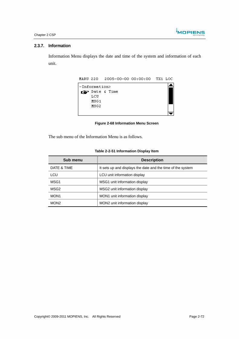
Chapter 2 CSP
Copyright© 2009-2011 MOPIENS, Inc. All Rights Reserved Page 2-72
2.3.7. Information
Information Menu displays the date and time of the system and information of each
unit.
Figure 2-68 Information Menu Screen
The sub menu of the Information Menu is as follows.
Table 2-2-51 Information Display Item
Sub menu Description
DATE & TIME It sets up and displays the date and the time of the system
LCU LCU unit information display
MSG1 MSG1 unit information display
MSG2 MSG2 unit information display
MON1 MON1 unit information display
MON2 MON2 unit information display
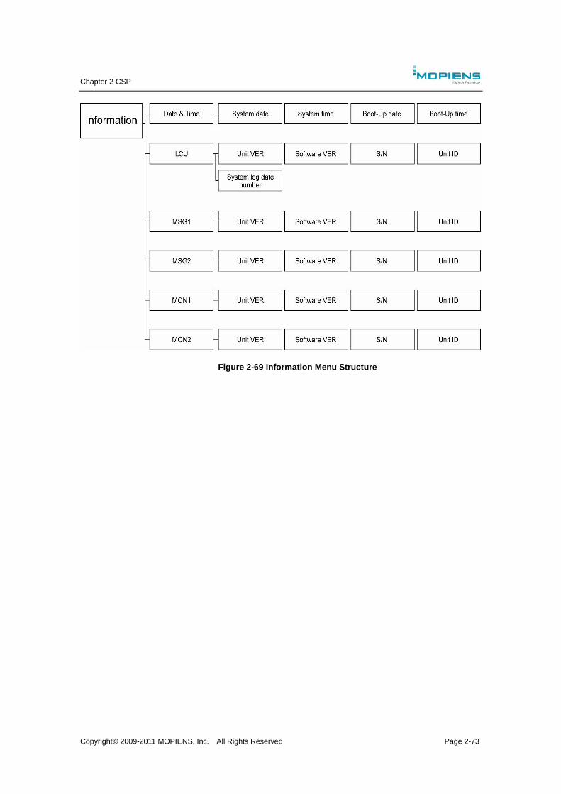
Chapter 2 CSP
Copyright© 2009-2011 MOPIENS, Inc. All Rights Reserved Page 2-73
Figure 2-69 Information Menu Structure
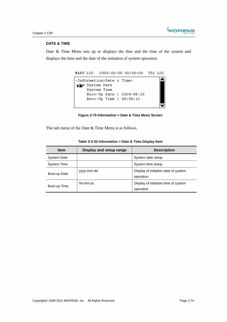
Chapter 2 CSP
Copyright© 2009-2011 MOPIENS, Inc. All Rights Reserved Page 2-74
DATE & TIME
Date & Time Menu sets up or displays the date and the time of the system and
displays the time and the date of the initiation of system operation.
Figure 2-70 Information > Date & Time Menu Screen
The sub menu of the Date & Time Menu is as follows.
Table 2-2-52 Information > Date & Time Display Item
Item Display and setup range Description
System Date System date setup
System Time System time setup
Boot-up Date yyyy-mm-dd Display of initiation date of system
operation
Boot-up Time hh:mm:ss Display of initiation time of system
operation
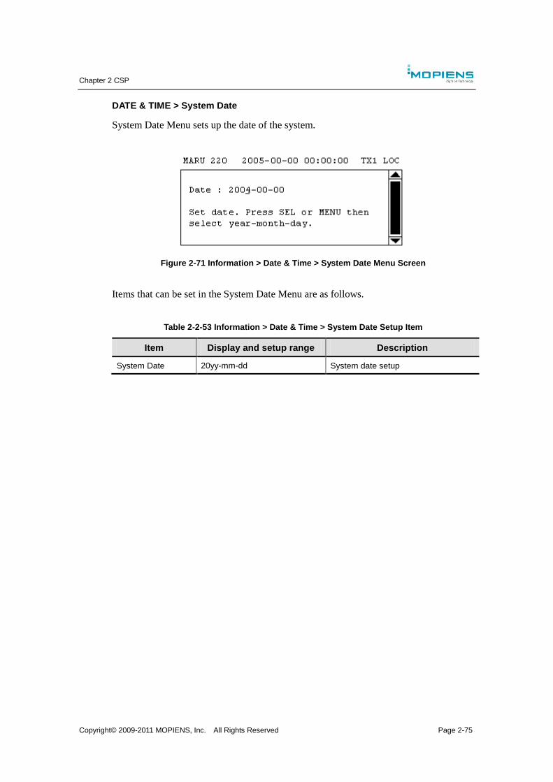
Chapter 2 CSP
Copyright© 2009-2011 MOPIENS, Inc. All Rights Reserved Page 2-75
DATE & TIME > System Date
System Date Menu sets up the date of the system.
Figure 2-71 Information > Date & Time > System Date Menu Screen
Items that can be set in the System Date Menu are as follows.
Table 2-2-53 Information > Date & Time > System Date Setup Item
Item Display and setup range Description
System Date 20yy-mm-dd System date setup
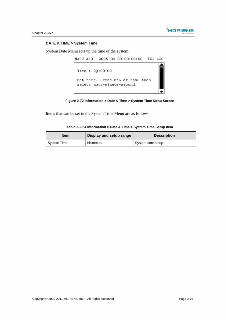
Chapter 2 CSP
Copyright© 2009-2011 MOPIENS, Inc. All Rights Reserved Page 2-76
DATE & TIME > System Time
System Date Menu sets up the time of the system.
Figure 2-72 Information > Date & Time > System Time Menu Screen
Items that can be set in the System Time Menu are as follows.
Table 2-2-54 Information > Date & Time > System Time Setup Item
Item Display and setup range Description
System Time hh:mm:ss System time setup
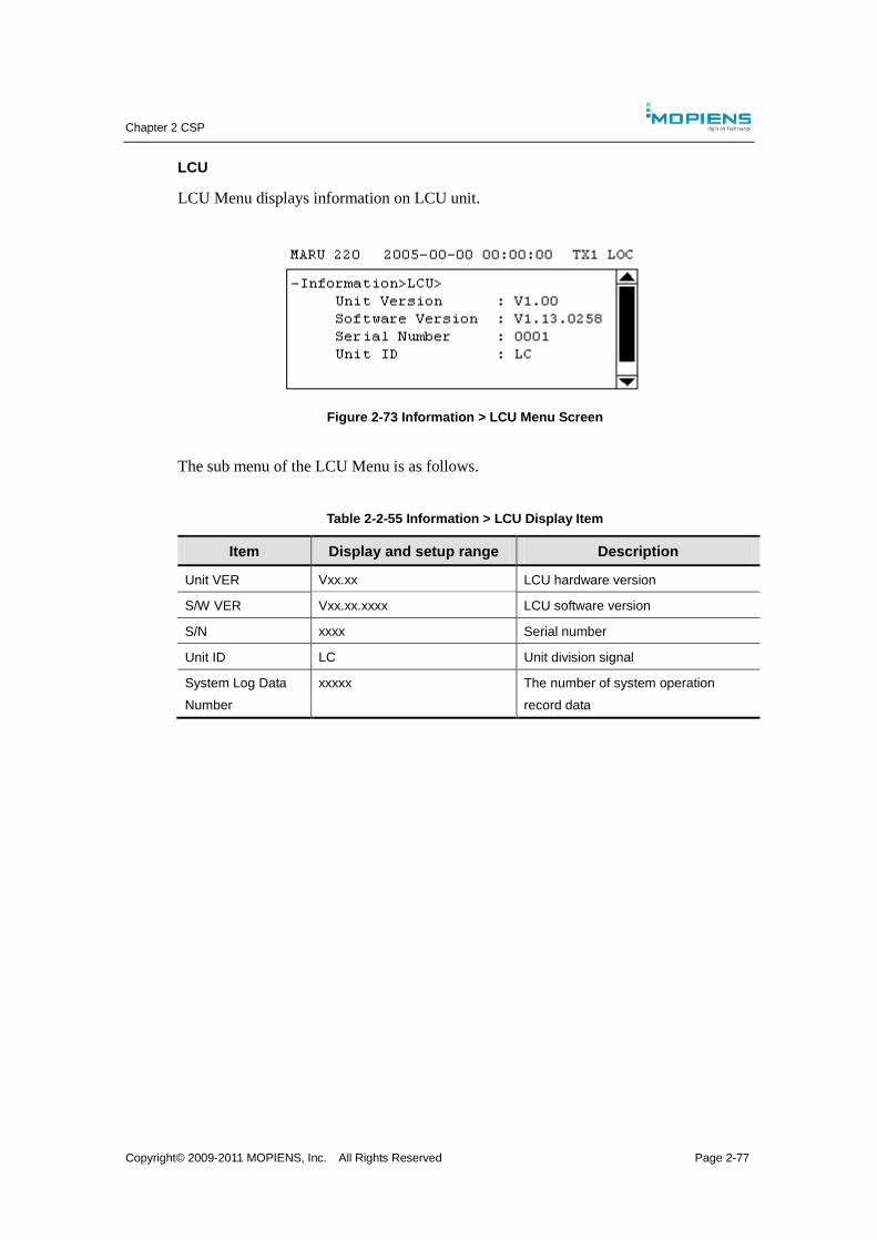
Chapter 2 CSP
Copyright© 2009-2011 MOPIENS, Inc. All Rights Reserved Page 2-77
LCU
LCU Menu displays information on LCU unit.
Figure 2-73 Information > LCU Menu Screen
The sub menu of the LCU Menu is as follows.
Table 2-2-55 Information > LCU Display Item
Item Display and setup range Description
Unit VER Vxx.xx LCU hardware version
S/W VER Vxx.xx.xxxx LCU software version
S/N xxxx Serial number
Unit ID LC Unit division signal
System Log Data
Number
xxxxx The number of system operation
record data

Chapter 2 CSP
Copyright© 2009-2011 MOPIENS, Inc. All Rights Reserved Page 2-78
MSG1, MSG2
MSG1 and MSG2 Menus display information on each MSG unit.
Figure 2-74 Information > MSG1 / 2 Menu Screen
The sub menu of the MSG1 / 2 Menu is as follows.
Table 2-2-56 Information > MSG1 / 2 Display Item
Item Display and setup range Description
Unit VER Vxx.xx MSG hardware version
S/W VER Vxx.xx.xxxx MSG software version
S/N xxxx Serial number
Unit ID G1 / G2 Unit division signal
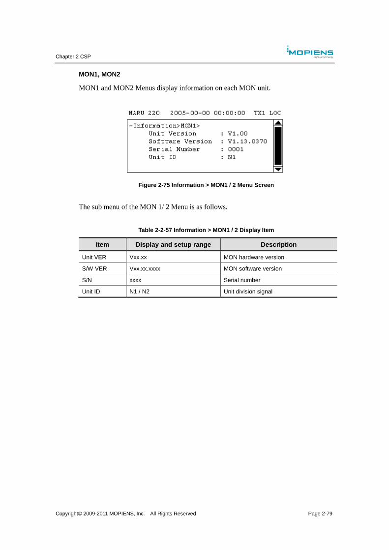
Chapter 2 CSP
Copyright© 2009-2011 MOPIENS, Inc. All Rights Reserved Page 2-79
MON1, MON2
MON1 and MON2 Menus display information on each MON unit.
Figure 2-75 Information > MON1 / 2 Menu Screen
The sub menu of the MON 1/ 2 Menu is as follows.
Table 2-2-57 Information > MON1 / 2 Display Item
Item Display and setup range Description
Unit VER Vxx.xx MON hardware version
S/W VER Vxx.xx.xxxx MON software version
S/N xxxx Serial number
Unit ID N1 / N2 Unit division signal

Chapter 2 CSP
Copyright© 2009-2011 MOPIENS, Inc. All Rights Reserved Page 2-80

Chapter 3 OPERATION
Copyright© 2009-2011 MOPIENS, Inc. All Rights Reserved Page 3-1
Chapter 3. OPERATION
3.1. Overview
Standard operation is normally carried out via a remote control interface with the user
program LMMS or RMMS installed on a PC. Also almost all the same functions can
be carried out with the control status panel (CSP). It is interfaced with the local
control unit (LCU) for main status indication, equipment status and measurement data
and manual controls (switch commands) for basic control functions. Normally the
alignment procedure and the maintenance are performed with a locally connected PC
using the LMMS.
3.2. Equipment Power On & Power Off
Before Power on the equipment, make sure the followings:
All the transmitter antenna cables are connected properly.
All the monitor antenna cables are connected properly.
The standby transmitter output is connected to the dummy load.
The mains power is connected to a proper AC source and the input voltage is
within the tolerance range.
Backup batteries are connected to the equipment properly.
An RS-232C direct cable (9-pin DSUB male to female) is connected to LMMS
PC’s serial port.
All remote links are connected to the equipment properly.
To turn on the equipment:
Turn on the AC/DC1’ INPUT circuit breaker switch
Turn on the AC/DC2’s INPUT circuit breaker switch
Turn on the DC/DC1’s INPUT circuit breaker switch
Turn on the DC/DC2’s INPUT circuit breaker switch
Turn on the DC/DC1’s BATTERY circuit breaker switch
Turn on the DC/DC2’s BATTERY circuit breaker switch
To turn off the equipment:
Turn on the DC/DC2’s BATTERY circuit breaker switch
Turn on the DC/DC1’s BATTERY circuit breaker switch
Chapter 3 OPERATION
Copyright© 2009-2011 MOPIENS, Inc. All Rights Reserved Page 3-2
Turn on the DC/DC2’s INPUT circuit breaker switch
Turn on the DC/DC1’s INPUT circuit breaker switch
Turn on the AC/DC2’s INPUT circuit breaker switch
Turn on the AC/DC1’ INPUT circuit breaker switch
3.3. Bypassing Monitors
During normal operation, the monitors need to be in ACTIVE state, so that any
anomaly in the radiated signal quality can be result in either transfer to standby
transmitter or shutting down the VOR completely.
Also, all of the commands that change system parameters are inhibited when the
monitors are in ACTIVE state. Therefore it is necessary to BYPASS the monitors
before making any change in system configuration.
Bypassing monitors can be done using LMMS or RMMS, in which case a proper
level of security login should be done first. Alternatively bypassing monitors can be
done using CSP or RCMU, in which case no need to log on.
During the monitor bypass operation, it is highly advised that the IDENT is disabled
unless the radiated signal quality is in absolute normal.
Also it should be kept in mind that after finishing any maintenance works, the
monitors should return to ACTIVE state.
3.4. Using LMMS/RMMS
The LMMS and RMMS is a MS Windows based program running on an IBM PC
compatible computer. In fact, they are not two different programs, but a single the
same program with different configurations. The LMMS is normally installed at close
vicinity of the main cabinet and connected via a direct RS-232C link. The RMMS is
normally installed at distant place using a leased-line modem or dialup modem. The
switching over between LMMS and RMMS can be done by changing the program
configuration file.
For details on using the LMMS or RMMS, refer to chapter 1.
3.5. Using CSP/RCMU

Chapter 3 OPERATION
Copyright© 2009-2011 MOPIENS, Inc. All Rights Reserved Page 3-3
For using the CSP or RCMU, refer to chapter 2.

Chapter 3 OPERATION
Copyright© 2009-2011 MOPIENS, Inc. All Rights Reserved Page 3-4
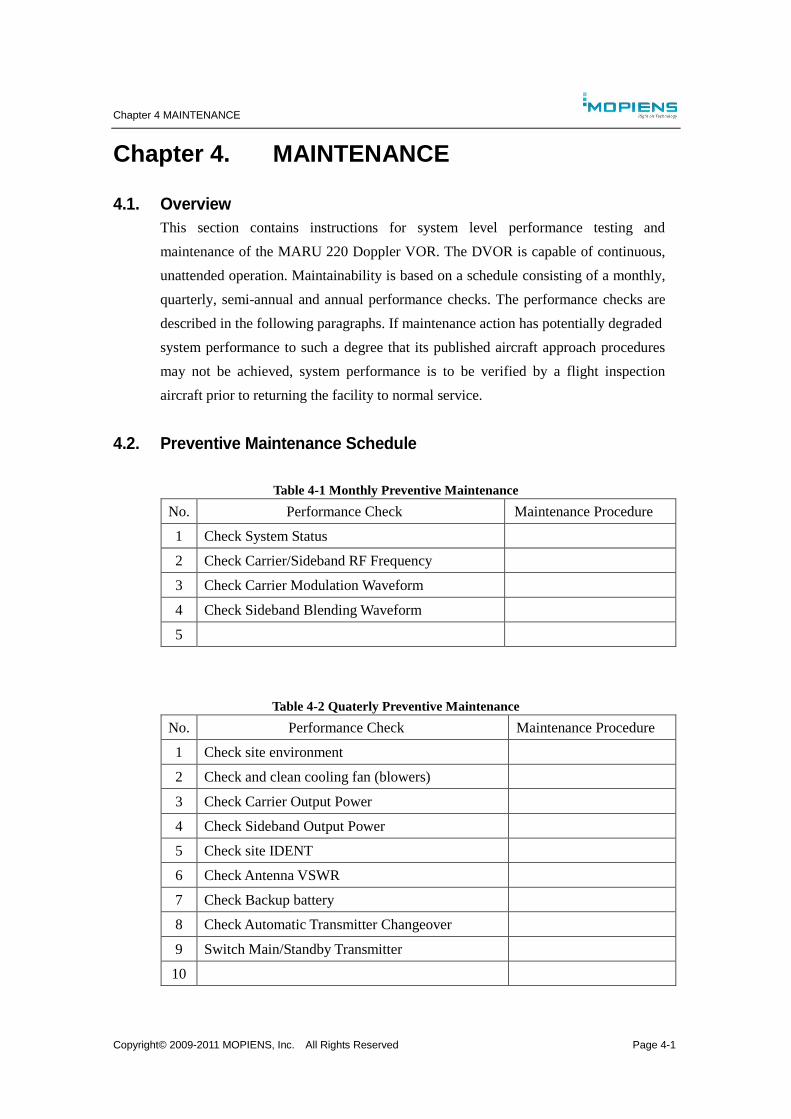
Chapter 4 MAINTENANCE
Copyright© 2009-2011 MOPIENS, Inc. All Rights Reserved Page 4-1
Chapter 4. MAINTENANCE
4.1. Overview
This section contains instructions for system level performance testing and
maintenance of the MARU 220 Doppler VOR. The DVOR is capable of continuous,
unattended operation. Maintainability is based on a schedule consisting of a monthly,
quarterly, semi-annual and annual performance checks. The performance checks are
described in the following paragraphs. If maintenance action has potentially degraded
system performance to such a degree that its published aircraft approach procedures
may not be achieved, system performance is to be verified by a flight inspection
aircraft prior to returning the facility to normal service.
4.2. Preventive Maintenance Schedule
Table 4-1 Monthly Preventive Maintenance
No. Performance Check Maintenance Procedure
1 Check System Status
2 Check Carrier/Sideband RF Frequency
3 Check Carrier Modulation Waveform
4 Check Sideband Blending Waveform
5
Table 4-2 Quaterly Preventive Maintenance
No. Performance Check Maintenance Procedure
1 Check site environment
2 Check and clean cooling fan (blowers)
3 Check Carrier Output Power
4 Check Sideband Output Power
5 Check site IDENT
6 Check Antenna VSWR
7 Check Backup battery
8 Check Automatic Transmitter Changeover
9 Switch Main/Standby Transmitter
10
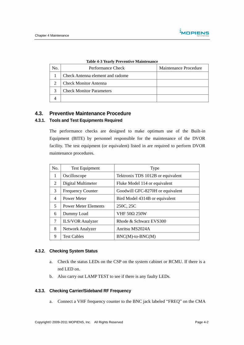
Chapter 4 Maintenance
Copyright© 2009-2011 MOPIENS, Inc. All Rights Reserved Page 4-2
Table 4-3 Yearly Preventive Maintenance
No. Performance Check Maintenance Procedure
1 Check Antenna element and radome
2 Check Monitor Antenna
3 Check Monitor Parameters
4
4.3. Preventive Maintenance Procedure
4.3.1. Tools and Test Equipments Required
The performance checks are designed to make optimum use of the Built-in
Equipment (BITE) by personnel responsible for the maintenance of the DVOR
facility. The test equipment (or equivalent) listed in are required to perform DVOR
maintenance procedures.
No. Test Equipment Type
1 Oscilloscope Tektronix TDS 1012B or equivalent
2 Digital Multimeter Fluke Model 114 or equivalent
3 Frequency Counter Goodwill GFC-8270H or equivalent
4 Power Meter Bird Model 4314B or equivalent
5 Power Meter Elements 250C, 25C
6 Dummy Load VHF 50Ω 250W
7 ILS/VOR Analyzer Rhode & Schwarz EVS300
8 Network Analyzer Anritsu MS2024A
9 Test Cables BNC(M)-to-BNC(M)
4.3.2. Checking System Status
a. Check the status LEDs on the CSP on the system cabinet or RCMU. If there is a
red LED on.
b. Also carry out LAMP TEST to see if there is any faulty LEDs.
4.3.3. Checking Carrier/Sideband RF Frequency
a. Connect a VHF frequency counter to the BNC jack labeled “FREQ” on the CMA
Chapter 4 Maintenance
Copyright© 2009-2011 MOPIENS, Inc. All Rights Reserved Page 4-3
and SMA using a BNC(M) to BNC(M) test cable.
b. Verify that the measured is in the frequency tolerance range.
4.3.4. Checking Carrier Modulation Waveform
a. Connect an oscilloscope to the BNC jack labeled “CAR MOD” on the front panel
of MSG using a BNC(M)-to-BNC(M) test cable.
b. Go to the TRANSMITTER tab on the LMMS/RMMS to disable IDENT keying
and voice modulation.
c. Verify that a clean 30Hz sine wave signal is observed on the oscilloscope screen.
4.3.5. Checking Site Environment
a. Check that the site is clear of any new obstructions or materials which could
affect the normal operation of the DVOR system.
b. Check the shelter, inside and out, for any sign of water filtration, damage, or
other deterioration.
c. Check the condition of the air conditioner, shelter lighting, obstruction lights,
baseboard heaters, electrical outlets, lightening arrestors, etc.
d. Check for and remove any accumulation of snow, ice, or debris on the field
monitor antennas.
e. Check for and remove any accumulation of snow, ice or debris on the
counterpoise surface.
4.3.6. Checking Carrier Output Power
a. Verify that transmitter 1 is operating.
b. Select Transmitter 1 tab in the LMMS/RMMS screen. Typically Carrier Power is
set for 100 watts (en route) or 50 watts (terminal).
c. Verify the carrier power output is within ±10% of the setting.
d. Go to System tab and manually changeover to transmitter 2.
e. Verify the carrier power output is within ±10% of the setting.
4.3.7. Checking Sideband Output Power
a. Verify that transmitter 1 is operating.
b. Select Transmitter 1 tab in the LMMS/RMMS screen. Typically Sideband Power
Chapter 4 Maintenance
Copyright© 2009-2011 MOPIENS, Inc. All Rights Reserved Page 4-4
is set for 2.5 watts depending on the 9960 Hz subcarrier Modulation depth.
c. Verify each sideband power output is within ±10% of the setting.
d. Go to System tab and manually changeover to transmitter 2.
e. Verify each sideband power output is within ±10% of the setting.
4.3.8. Checking site IDENT
a. Go to monitor tab.
b. Check for IDENT code and modulation depth.
c. Go to system tab.
d. Open IDENT sound control dialog box.
e. Choose “Sound from MON1” or “Sound from MON2”.
f. Verify the site IDENT Morse code is heared.
4.3.9. Checking Antenna VSWR
Checking Carrier Antenna VSWR:
a. Disable Carrier Amplifier
b. Disconnect the coaxial cable from the carrier antenna.
c. Get a vector network analyzer and carry out one port calibration.
d. Connect the network analyzer port 1 to the carrier antenna.
e. Set the analyzer in VSWR display format and measure S11 parameter.
Checking Sideband Antenna VSWR:
a. Disable Sideband Amplifiers
b. Disconnect the coaxial cable from the ASU inputs.
c. Get a vector network analyzer and carry out one port calibration.
d. Set the analyzer in VSWR display format for S11 parameter measurement.
e. Connect the network analyzer port 1 to the ASU input.
f. Go to TRANSMITTER tab in the LMMS/RMMS and set Antenna Test Mode.
g. Choose a sideband antenna and measure VSWR.
h. Change to next antenna and repeat the measurement for all 48 sideband antennas.
4.3.10. Checking Backup Battery
a. Turn off the INPUT circuit breaker switch on the AC/DC1.
b. Turn off the INPUT circuit breaker switch on the AC/DC2.
c. Verify that the system still up and running.
Chapter 4 Maintenance
Copyright© 2009-2011 MOPIENS, Inc. All Rights Reserved Page 4-5
4.3.11. Checking Automatic Transmitter Changeover
a. Bypass both monitors.
b. Go to MONITOR tab on the LMMS/RMMS screen.
c. Click on the Azimuth box.
d. Change the azimuth reference value by 1.5 degrees.
e. As soon as the change comes into effect, clear the monitor bypass mode.
f. Wait and verify that the system is transferred to the standby transmitter.
g. Wait again and verify the system is shutdown completely.
h. Bypass both monitors and return the azimuth reference value.
4.3.12. Switching Main / Standby Transmitter
a. Go to SYSTEM tab on the LMMS/RMMS screen.
b. Click on the CHANGEOVER box.
c. Click on YES on changeover confirmation message.
4.3.13. Checking Antenna Element and Radome
a. Go to TRANSMITTER 1 tab and disable CPA, LSB SMA and USB SMA.
b. Go to TRANSMITTER 2 tab and disable CPA, LSB SMA and USB SMA.
c. Go up to the counterpoise and visually inspect each antenna cover radome.
d. Open each antenna cover and visually inspect each antenna element.
4.3.14. Checking Monitor Antenna
a. Approach the monitor antenna tower
b. Visually inspect the monitor antenna tower for any mechanical and/or
environmental damages such as corrosion.
c. Visually inspect the monitor antenna and the feeder cable.
4.3.15. Checking Monitor Parameters
a. Go to MONITOR tab on the LMMS/RMMS screen.
b. Verify all the monitor parameters are in normal color and within the tolerance
limits.

Chapter 4 Maintenance
Copyright© 2009-2011 MOPIENS, Inc. All Rights Reserved Page 4-6
Chapter 5 Installation
Copyright© 2009-2011 MOPIENS, Inc. All Rights Reserved Page 5-1
Chapter 5. INSTALLATION
5.1. SELECTING INSTALLATION SITE
The area in which a DVOR is to be installed is determined by the responsible Civil
Aviation Authority according to the international air traffic regulations. This area is
generally sufficiently large to allow a point with the optimum topography and thus the
optimum propagation conditions to be chosen. This point is determined by means of a
site survey at which a surveyor must always be present. When the installation site has
been determined, precise bearings must be taken, either with reference to
trigonometric points or, if available, via a DGPS for increased precision.

Chapter 5 Installation
Copyright© 2009-2011 MOPIENS, Inc. All Rights Reserved Page 5-2
5.2. FOUNDATIONS FOR DVOR COUNTERPOISE AND SHELTER
The following drawings show the foundations for counterpoises with heights of 4 m
and the corresponding shelter foundations. These drawings are for information only.
The drawings used for the installation site are provided by the engineering plan.
Shelter plate foundation drawing details (for shelter foundation plate see Fig. 3)
Chapter 5 Installation
Copyright© 2009-2011 MOPIENS, Inc. All Rights Reserved Page 5-3
5.3. GROUNDING
5.3.1. General
The type of grounding implemented is dependent on the local terrain. Consequently it
is only possible to provide general guidelines here. Grounding conductors or rods are
metallic elements of a particular form which are either driven into the ground or laid
in the ground so as to cover a relatively large area. All connections in the ground must
be welded and protected against corrosion. The ground resistance required for a
DVOR (or other navigation installations) can be given as ≤ 5 . This resistance can
only be measured precisely with the aid of special ground resistance measuring
equipment. The exact measuring procedure is described in the operating instructions
for these devices. Universally valid instructions are given in Para 5.3.6. Sufficient
grounding can generally be obtained if the installation suggestions described below
and the terrain conditions are paid attention to. When estimating the ground resistance
the length and extent of the network laid are the crucial points, not the cross−sectional
area of the conductors. Favorable resistance conditions are provided by arable land
and loamy ground (ground resistivity 100 per meter). The data specified below
applies to these conditions. With other types of terrain the factors below must be
taken into consideration (increase in the resistance with respect to the basic values
stated).
− Moist sandy soil 2x
− Dry sandy soil 5 to 10x
− Gravel or stones up to 30x
If the ground is not chemically neutral, e.g. if it is salty, it may be necessary to coat all
metal parts laid in the ground with lead or to use a sufficiently non-corrosive steel
(e.g. V2A). The different types are as follows:
Radial Ground rod or plate Interlinked ground
Fig. 36 Different types of ground conductor configuration
5.3.2. Strip or mesh Ground Conductors
Strip ground conductors take the form of a strip, round material or cable laid in the
ground at a depth of 0.5 to 1 m so as to cover a relatively large area.
Materials:
− Steel strip (hot galvanized) 100 mm2, min. thickness 3 mm
− Copper strip 50 mm2, min. thickness 2 mm
Chapter 5 Installation
Copyright© 2009-2011 MOPIENS, Inc. All Rights Reserved Page 5-4
− Copper cable (not finely stranded) 135 mm2
The network should be laid as symmetrical to the DVOR station as possible. The
necessary length and extension when laid in a straight line, should be estimated from
the basic data below.
− Strip length Ground resistance 25 m 10
50 m 5
100 m 3
5.3.3. Ground Rods
Ground rods are either pipes or U, L or T-shaped profiles driven vertically into the
ground and 1 to 2 m in length. It is necessary to connect several ground rods together
in order to reduce the grounding resistance. The minimum spacing is twice the length
of each ground rod.
− Material: Steel (hot galvanized) Pipe 30 x 3 mm
Bracket L 65 x 65 x 7 mm
U−profile U 65 DIN 1026
T−profile T 60 DIN 1024
− Probable grounding resistance of a rod: Length 1 m approx. 70
Length 2 m approx. 40
The material, cross sectional areas and grounding resistance of the connecting leads to
the shelter should be as for strip ground conductors, (see Para 5.3.2). When pipe-type
grounding rods are fastened with clamps, screws at least M10 in size should be used.
5.3.4. Ground Plates
Ground plates are solid perforated sheet metal plates with dimensions of approx. 0.5 x
1 m or 1 x 1 m, which are embedded vertically in the ground. The top edge of the
plates should always be at least 1 m below the surface. Several ground plates must be
connected in parallel in order to reduce the grounding resistance. The minimum
spacing should be 3 m. Material:
− Sheet steel (hot galvanized) min. thickness 3 mm
Chapter 5 Installation
Copyright© 2009-2011 MOPIENS, Inc. All Rights Reserved Page 5-5
− Sheet copper min. thickness 2 mm
The ground resistance of a plate 1 m2 is approx. 30 . The data for the connecting
conductors is specified in the tables in Para 5.3.2.
5.3.5. Estimating the Ground Resistance
The resistance of each rod, each plate and each supply line used should be determined
on the basis of Para 5.3.2 to 5.3.4. They should be considered as parallel resistances.
The resulting grounding resistance should then be calculated as follows: 1/Rres
=1/R1+1/R2+1/R3+...+ 1/Rn. Taking into account the nature of the terrain (for factors
see Para 5.3.1) satisfactory grounding conditions can be assumed if the ground
resistance calculated from the base data is < 5 . If the value calculated is 5 or
more, measuring the ground resistance is recommended.
5.3.6. Measuring the Ground Resistance
Three measurements must be performed over a large area in order to determine the
ground resistance precisely. The distance between two auxiliary grounds required
must be large in relation to the complete ground network of the navigation installation.
Two steel rods approx. 1 m long should be used as auxiliary grounds (reinforcing
bars); these should be driven into the ground with only a few centimeters remaining at
the designated points. It is essential that the rods are of equal length and are driven in
to the same depth.
Example of a DVOR plate ground with 5 x 2 plates, each 1 m2. The drawing is not to
scale. A theoretical round resistance of approx. 2 (good) would be obtained on the
basis of the 10 plates, connecting conductors and assumed terrain conditions (e.g.
arable land) in accordance with the formula in Para 5.3.5
Measurements are performed as shown in the diagram below:
E = Installation ground
H1= Auxiliary ground 1
H2= Auxiliary ground 2
M1= Measured value 1
M2= Measured value 2
M3= Measured value 3
Chapter 5 Installation
Copyright© 2009-2011 MOPIENS, Inc. All Rights Reserved Page 5-6
Measured value 1: Resistance between installation ground and auxiliary ground 1
Measured value 2: Resistance between auxiliary ground 1 and auxiliary ground 2
Measured value 3: Resistance between installation ground and auxiliary ground 2
When the three measurements have been performed the ground resistance is
calculated as follows:
Ground resistance = (corr. meas. 1 + corr. meas. 3 − corr. meas. 2) / 2
The measurement is falsified by the resistance of the two test leads. The cross−
sectional area of the test leads should not be less than 1.5 mm2 in order to ensure an
adequate breaking strength. With this cross−sectional area and an assumed length of 2
x 25 m = 50 m, the falsifying resistance would be 0.58 . This resistance should
therefore be measured and deducted from measured values 1, 2
and 3. The measured values corrected in this manner are entered into the above
formula.
Chapter 5 Installation
Copyright© 2009-2011 MOPIENS, Inc. All Rights Reserved Page 5-7
5.4. INSTALLING EQUIPMENT SHELTER
5.4.1. General
The Navaids equipment can be installed in a 3m x 5m Standard Shelter which is
offered by MOPIENS, Inc. To cover the requirements, the shelter is based on the
definition on transport containers ISO/KS standards. The shelter consists of a self-
supporting, distortion resistant steel frame construction with eight ISO corners and
walls made of fiber-reinforced plastic (FRP) in standardized container dimensions.
During installation, the shelter should be placed on the foundations such that the door
is oriented according to the site survey and project drawings. The shelter is anchored
to the four foundation blocks using the ISO corners and twist locks. The power supply
(mains) and signal (remote control, field monitor) feeder cables enter from below
through openings in the shelter floor.
5.4.2. Installing Equipment Shelter
When transporting by crane or helicopter, care should be taken to ensure that the
angle between the lifting harness and the crate is at least 60°.
Chapter 5 Installation
Copyright© 2009-2011 MOPIENS, Inc. All Rights Reserved Page 5-8
5.5. INSTALLING ANTENNAS
5.5.1. General
This chapter describes the installation and adjustment of the DVOR antennas. The
installation of the counterpoise with associated supports and framework, and the
framework decking are normally part of the civil works section and not included in
this description. The counterpoise foundation drawing in section 5.2 is shown for
information only. It depends on actual siting conditions.
WARNING
Sturdy shoes, safety gloves and safety helmets must be worn during
installation. Safety belts with rescue line and swivel snaphook should be
used when working on the counterpoise platform.
5.5.1.1. Prerequisites
Counterpoise
The counterpoise for the DVOR antenna has been completely assembled according to
the drawings set included with the counterpoise material.
NOTE: Building up the counterpoise and the antenna mounting devices it is to
ensure that the counterpoise surface constitutes a homogeneous RF plane.
The metallic parts (e.g. mesh web, antenna ring etc.) of the surface should be
conductive interconnected so that the antennas will find adequate RF
radiation conditions.
Support for Carrier Antenna (Counterpoise Center)
The support for mounting the middle antenna has been installed in the center of the
counterpoise. Permissible deviation from the center: ±150 mm.
Antenna Ring
(Fig. 7)
The antenna ring has been installed on the counterpoise. The radius measured at the
inner ring is 6623 mm.
Cable Run
Chapter 5 Installation
Copyright© 2009-2011 MOPIENS, Inc. All Rights Reserved Page 5-9
(optional, Fig. 8)
As default the RF cables are fed through the mesh clamps or using steel hooks below
the counterpoise. Alternatively 16 plastic or steel pipes may be optionally installed on
the lower side of the counterpoise for the cable runs from the sideband antennas to the
center of the counterpoise. A further pipe may be used in addition if the antenna of a
collocated DME is to be installed.
5.5.2. Antenna mounting
5.5.2.1. Placing the Antennas onto the Counterpoise
The DVOR antennas comprising antenna dome, matching stub, balun and pedestal are
lifted with their packaging over the outer edge and onto the counterpoise. To do this,
the use of a lifting crane, a trestle with swiveling arm or, e.g. for the 4 m-high
counterpoise, a guyed auxiliary mast is recommended (Fig. 9).
5.5.2.2. Installing the Carrier Antenna
Determine the center of the counterpoise with respect to the antenna ring of the
sideband antennas. Install the pedestal of the carrier antenna at this point, then align it
using a spirit level (compensate if necessary by means of washers, etc.) and secure.
Mount the carrier antenna with cover on the pedestal and secure with the appropriate
screws.
CAUTION
When removing the cover, always make sure that no rain can penetrate
the lower section of the antenna or come into contact with the antenna
elements.
5.5.2.3. Installation of the Sideband Antennas
First install the sideband antenna A1. The installation point of this antenna should be
selected with the aid of a compass such that it is aligned approximately with North
with respect to the middle antenna. Mark the installation point on the antenna ring.
Install pedestal #1 here, and align it perpendicularly with the aid of a spirit level (if
necessary compensate by means of washers or similar). Secure the pedestal to the
antenna ring by means of a clamping plate and four screws. Secure all pedestal
fastenings to the outer ring.
Install the sideband antenna A2 in the same way as A1 and to the left of it (as seen
Chapter 5 Installation
Copyright© 2009-2011 MOPIENS, Inc. All Rights Reserved Page 5-10
from the carrier antenna), such that with a pedestal diameter of 127 mm the distance
between the outer edge of pedestal #1 and the outer edge of pedestal #2 is 750 mm.
This distance can be set anticlockwise from antenna to antenna using improved means
(e.g. a wooden rod cut to size).
NOTE: 750 mm is a standard dimension, which may vary somewhat in
practice on account of tolerance chains within the antenna ring and the
pedestals. In such cases a positive or negative deviation from the standard
dimension of 750 mm will be measured between A48 and A1. This dimension
(deviation from 750 mm) should be divided by 48, in order to calculate a new
clearance. The pedestals are then readjusted with a new wooden rod in a
second procedure. Each pedestal adjusted must also be aligned precisely
using a spirit level.
The hooks on both sides of the antenna ring holding a layer of structural steel matting
should be adjusted as necessary in order to ensure that they are firmly secured. The
hooks ensure adequate electrical connection.
Careful, precise mechanical alignment of the antenna will considerably simplify the
work of the commissioning engineer. A maximum deviation of 3 mm between A48
and A1 with respect to the corrected standard dimension can be tolerated. A sideband
antenna (with cover) should now be mounted on each pedestal.
5.5.3. RF Cabling of Antennas
5.5.3.1. General
The RF cables between the sideband antennas and the ASU connectors below the
counterpoise are marked from A1 to A48 at both ends by means of cable markers, as
well as the RF cable from the lead through in the shelter wall to the carrier antenna
with A0. The other 4 RF cables from the lead through in the shelter wall to the ASU
housing are also marked with LSB COS, LSB SIN, USB COS and USB SIN at both
ends. The SB antenna RF cables A1 to A48 are fed to the lead through in the shelter
wall and from there to the antennas. Due to the different counterpoise height options
there are sets with individual cable length for each.
CAUTION

Chapter 5 Installation
Copyright© 2009-2011 MOPIENS, Inc. All Rights Reserved Page 5-11
Make sure that no bend in an RF−cable is made with a radius of less
than 50 mm. The supply cables at the ASU should be laid such that
they form a sufficiently large loop to prevent any rainwater running
down the cables and coming into contact with the coaxial connections
of the ASU.
5.5.3.2. Sideband Antennas
Slide the individual RF cables A1 to A48 and A0 each through the pedestal of the
corresponding sideband antenna from below, connect the coaxial connector to the
antenna connection socket and secure with the union nut. Feed the other end of the
cable, except that for the carrier antenna A0 through corresponding mesh clamps used
as cable duct to the U-girder and from there to the lead through (48x SB ANT, 1x
CAR ANT, 1x MON ANT) of the shelter via the cable box.
Provide strain relief for the cable underneath the pedestal by means of UV-resistant
cable ties. Excessive lengths of cable are cleared in a cable box at the lower end of the
U-girder. The RF cabling of the individual sideband antennas to the shelter should be
installed such that, for example, the cable from the central connection of the antenna
of antenna A2 is fed to terminal A2 of the coaxial connector at the lead through of the
shelter.
The supply cables at the shelter should be laid such that they form a sufficiently large
loop to prevent any rainwater running down the cables and coming into contact with
the coaxial screw connections in the wall entrance. The cable loops should be
protected by means of a suitable cover.
5.5.4. Aligning Sideband Antennas
CAUTION
Care should be taken when removing the covers from the carrier and
sideband antennas to ensure that no rain can penetrate into the lower
section of the antenna or come into contact with the antenna elements.
Remove the cover from the carrier antenna, secured by with of 8 self-tapping,
stainless steel round-head screws 5 x 30 mm. Take the rectangular tube and pin from
the installation accessories for the DVOR system, and install them at the center of the
Chapter 5 Installation
Copyright© 2009-2011 MOPIENS, Inc. All Rights Reserved Page 5-12
carrier antenna. The pin can be used to take bearings when aligning the 48 sideband
antennas.
Remove the cover from one of the sideband antennas (e.g. A1). Preset the two
calibration capacitors of each antenna, each with two plates adjustable by means of a
threaded shaft and fastened by means of a lock nut. The plates should be roughly
symmetrical between the antenna elements and spaced properly (6.7 mm for 113
MHz). This spacing is easy to set if a suitable twist drill shaft is used as a gauge. The
lock nuts should be tightened following the setting.
Loosen the three mounting bolts for the antenna lower section/pedestal, and move the
lower section of the antenna slightly to the left and right on the pedestal in accordance
with the oblong holes in the pedestal. Using the rectangular tube, align the various
sideband antennas from the outside of the installation ring via the pointer sights
(press-fitted at the top of the antenna lower section) to the pin (bearing marker),
which is mounted on the center of the middle antenna. The three screws (for securing
the antenna lower section to the pedestal) should be tightened following the setting.
Bearings should be taken with respect to the middle antenna several times if necessary,
and the adjustment repeated. When the lower section of the antenna has been secured
to the pedestal the cover should be installed. The 8 self-tapping screws for securing
the cover should only be screwed in roughly half way, since further calibrations are
likely to be necessary during commissioning.
Following these operations, or in the event that they are not necessary, secure the
cover by means of the 8 screws. If damage is determined in the coated polystyrene
body of the lower section of the antenna, it should be repaired immediately using the
repair kit.
5.5.5. Installing Field Monitor Antenna
The monitor dipole is mounted on a mast at a height of 1.3 m above the antenna
counterpoise. It should be installed at a distance of 100 m or farther from the center of
the counterpoise. It is generally installed at the radial of major use. The supply cable
is fed via a cable trench to the DVOR housing.
Chapter 5 Installation
Copyright© 2009-2011 MOPIENS, Inc. All Rights Reserved Page 5-13
5.6. INSTALLING DVOR EQUIPMENTS
5.6.1. General
This chapter describes the connections at the transmitter: power supply, RF
connections, interface connections and connections for remote control equipments.
NOTE: If the shelter is provided by the customer, the customer will be
responsible for the installation including a mains fuse box with arrester and a
battery fuse box.
5.6.2. Connecting Power Supply
5.6.2.1. Power Connections
A type MS-3057-12A circular male connector (Jack) with three prongs for main AC
power supply is located on the top of the main equipment cabinet.
The connection must be done in the following sequence:
WARNING
Before connecting the cables check that the mains lead is not hot and
that the battery is not connected.
a) Set the POWER ON/OFF switches of the AC/DC units to OFF. Remove the units.
b) Prepare three wires for power connection in suitable length.
c) Solder the wires to the MIL-type circular plug included in the accessories kit
supplied with MARU 220 DVOR. Be sure to identify correct pin for L (Live), N
(Neutral), G (Ground)
d) Connect the circular plug to the circular jack labeled as AC MAINS IN on the top
plate of the equipment cabinet.
d) Connect the other end of the fabricated power cable to a main power source
(nominally AC 110 to 220 V 50/60 Hz, single phase) via power distribution panel of
the equipment shelter.
5.6.2.2. Connecting Backup Battery
Two MIL-type circular male connectors (Jacks) with two prongs for backup battery
are located on the top of the main equipment cabinet.
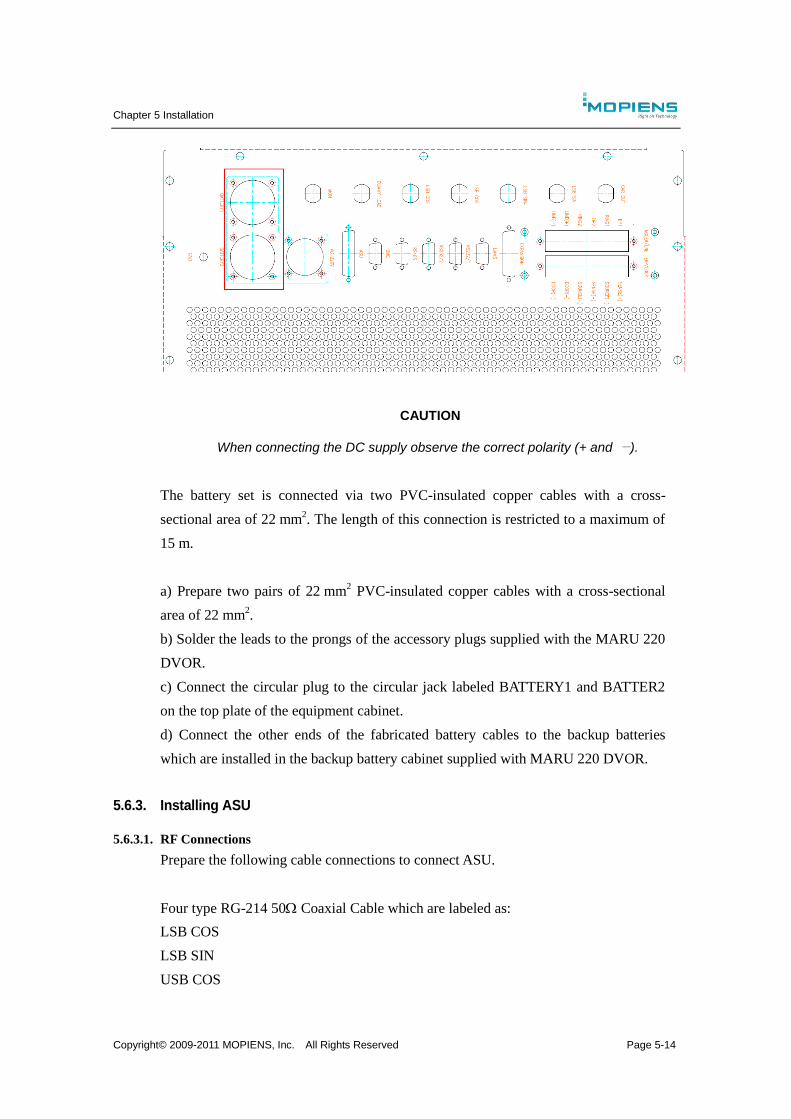
Chapter 5 Installation
Copyright© 2009-2011 MOPIENS, Inc. All Rights Reserved Page 5-14
CAUTION
When connecting the DC supply observe the correct polarity (+ and −).
The battery set is connected via two PVC-insulated copper cables with a cross-
sectional area of 22 mm2. The length of this connection is restricted to a maximum of
15 m.
a) Prepare two pairs of 22 mm2 PVC-insulated copper cables with a cross-sectional
area of 22 mm2.
b) Solder the leads to the prongs of the accessory plugs supplied with the MARU 220
DVOR.
c) Connect the circular plug to the circular jack labeled BATTERY1 and BATTER2
on the top plate of the equipment cabinet.
d) Connect the other ends of the fabricated battery cables to the backup batteries
which are installed in the backup battery cabinet supplied with MARU 220 DVOR.
5.6.3. Installing ASU
5.6.3.1. RF Connections
Prepare the following cable connections to connect ASU.
Four type RG-214 50 Coaxial Cable which are labeled as:
LSB COS
LSB SIN
USB COS
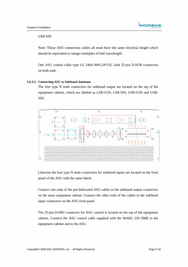
Chapter 5 Installation
Copyright© 2009-2011 MOPIENS, Inc. All Rights Reserved Page 5-15
USB SIN
Note: Those ASU connection cables all must have the same electrical length which
should be equivalent to integer multiples of half wavelength.
One ASU control cable type UL 2464 AWG24*25C with 25-pin D-SUB connectors
on both ends
5.6.3.2. Connecting ASU to Sideband Antennas
The four type N male connectors for sideband output are located on the top of the
equipment cabinet, which are labeled as LSB-COS, LSB-SIN, USB-COS and USB-
SIN.
Likewise the four type N male connectors for sideband inputs are located on the front
panel of the ASU with the same labels.
Connect one ends of the pre-fabricated ASU cables to the sideband output connectors
on the main equipment cabinet. Connect the other ends of the cables to the sideband
input connectors on the ASU front panel.
The 25-pin D-SBU connector for ASU control is located on the top of the equipment
cabinet. Connect the ASU control cable supplied with the MARU 220 DME to the
equipment cabinet and to the ASU.
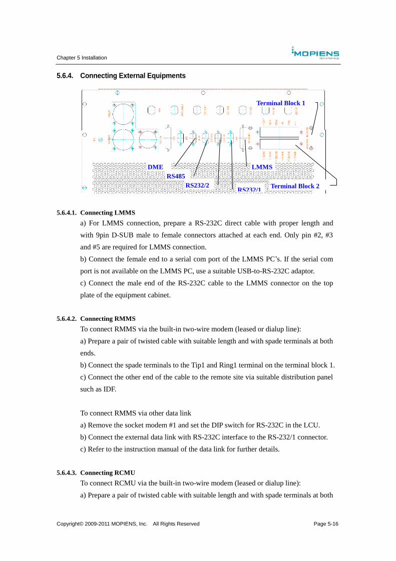
Chapter 5 Installation
Copyright© 2009-2011 MOPIENS, Inc. All Rights Reserved Page 5-16
5.6.4. Connecting External Equipments
5.6.4.1. Connecting LMMS
a) For LMMS connection, prepare a RS-232C direct cable with proper length and
with 9pin D-SUB male to female connectors attached at each end. Only pin #2, #3
and #5 are required for LMMS connection.
b) Connect the female end to a serial com port of the LMMS PC’s. If the serial com
port is not available on the LMMS PC, use a suitable USB-to-RS-232C adaptor.
c) Connect the male end of the RS-232C cable to the LMMS connector on the top
plate of the equipment cabinet.
5.6.4.2. Connecting RMMS
To connect RMMS via the built-in two-wire modem (leased or dialup line):
a) Prepare a pair of twisted cable with suitable length and with spade terminals at both
ends.
b) Connect the spade terminals to the Tip1 and Ring1 terminal on the terminal block 1.
c) Connect the other end of the cable to the remote site via suitable distribution panel
such as IDF.
To connect RMMS via other data link
a) Remove the socket modem #1 and set the DIP switch for RS-232C in the LCU.
b) Connect the external data link with RS-232C interface to the RS-232/1 connector.
c) Refer to the instruction manual of the data link for further details.
5.6.4.3. Connecting RCMU
To connect RCMU via the built-in two-wire modem (leased or dialup line):
a) Prepare a pair of twisted cable with suitable length and with spade terminals at both
LMMS DME
RS485
RS232/2 RS232/1
Terminal Block 2
Terminal Block 1
Chapter 5 Installation
Copyright© 2009-2011 MOPIENS, Inc. All Rights Reserved Page 5-17
ends.
b) Connect the spade terminals to the Tip2 and Ring2 terminal on the terminal block 1.
c) Connect the other end of the cable to the remote site via suitable distribution panel
such as IDF.
To connect RCMU via other data link
a) Remove the socket modem #2 and set the DIP switch for RS-232C in the LCU.
b) Connect the external data link with RS-232C interface to the RS-232/2 connector.
c) Refer to the instruction manual of the data link for further details.
5.6.4.4. Connection of Optional Voice Channel Signal
Connect a two wire line from incoming voice service (e.g. from Tower) to LINE(+)
and LINE(-) terminals on the terminal block 1 on top plate of the equipment cabinet.
5.6.4.5. Connection of auxiliary Inputs/Outputs (Expansion)
The Navaids installation contains an auxiliary interface (on LCU board) with 8 digital
inputs and 8 digital outputs for additional signals which is at the user’s disposal. The
external wiring is available on the 25-pin D-SUB connector labeled as EXPANSION
on the top plate of the equipment cabinet.
5.6.4.6. Connection of Environmental Sensors
Connect a PT-100 temperature sensor for ambient temperature measurement to the
SENS(+), SENS(-), SOURCE(+) and SOURCE(-) terminals of the terminal block 2
on the top plate of the equipment cabinet.

MARU 220 Doppler VHF Omni-directional Radio Range
Technical Manual
Volume II
OPERATIONS AND MAINTENANCE
INSTALLATION
Copyright© 2009-2011 MOPIENS, Inc.
All rights reserved
This document contains copyrighted and proprietary
information, which may not be disclosed to others for any
purposes without written permission from MOPIENS, Inc.
Top Related