


Languages
Pages
Legal

MIL-PRF-63029D(AV)23 August 1996
SUPERSEDINGMIL-M-63029C(AV)
20 March 1991
PERFORMANCE SPECIFICATION
MANUALS, TECHNICAL: REQUIREMENTS FOR OPERATOR’SMANUALS AND CHECKLISTS FOR AIRCRAFT
This specification is approved for use by US Army Aviation and Troop Command,Department of the Army, and is available for use by all departments and agencies ofthe Department of Defense.
1. SCOPE
1.1 Scope. This specification contains the requirements for preparing technical manuals(TMs) describing operating procedures, checklists, and maintenance test flight (MTF)checklists for operators of Army aircraft.
1.2 Classification. The TMs to be prepared in accordance with this specification include:
-10 - Operator’s Manual-CL - Operator’s Checklist-MTF - Maintenance Test Flight Checklist
Beneficial comments (recommendations, additions, deletions) and any pertinent datawhich may be of use in improving this document should be addressed to US Army,ATTN: AMSAT-R-EDS, 4300 Goodfellow Blvd., St. Louis, MO 63120-1798, byusing the self-addressed Standardization Document Improvement Proposal (DD Form1426) appearing at the end of this document or by letter. E-mail comments may besent to [email protected] or [email protected]. Send faxes to 314-263-1622, ATTN: AMSAT-R-EDS.
AMSC A6038 AREATMSS
DISTRIBUTION STATEMENT A. Approved for public release; distribution is unlimited.
NOT MEASUREMENTSENSITIVE
Downloaded from http://www.everyspec.com
MIL-PRF-63029D(AV)
2
1.3 Figures. In the event of a conflict between the text and the illustrations, the text of thisdocument takes precedence over the figures.
2. APPLICABLE DOCUMENTS
2.1 General. The documents listed in this section are specified in Sections 3 and 4 of thisspecification. This section does not include documents cited in other sections of this standard orrecommended for additional information or as examples. While every effort has been made toensure the completeness of this list, document users are cautioned that they must meet allspecified requirements documents cited in Sections 3 and 4 of this specification, whether or notthey are listed.
2.2 Government documents.
2.2.1 Specifications, standards, and handbooks. The following specifications, standards, andhandbooks form a part of this document to the extent specified herein. Unless otherwisespecified, the issues of these documents are those listed in the issue of the Department of DefenseIndex of Specifications and Standards (DODISS) and supplement thereto, cited in the solicitation(see 6.2).
STANDARDS
DEPARTMENT OF DEFENSE
MIL-STD-12 Abbreviations for Use on Drawings, Specifications,Standards and in Technical Documents
MIL-STD-210 Climatic Extremes for Military Equipment
MIL-STD-38784 DOD Standard Practice, General Style andFormatting Requirements for Technical Manuals
(Unless otherwise indicated, copies of the above specifications, standards, and handbooks areavailable from the Standardization Document Order Desk, 700 Robbins Avenue, Bldg 4D,Philadelphia, PA 19111-5094.)
2.3 Order of precedence. In the event of a conflict between the text of this document and thereferences cited herein, the text of this document takes precedence. Nothing in this documenthowever, supersedes applicable laws and regulations unless a specific exemption has beenobtained.
3. REQUIREMENTS3.1 General. This section is divided into general and detailed requirements. The generalprovisions shall cover overall qualities of the TMs that will be produced. Detailed requirementsshall deal with specific format, detailed preparation, and technical aspects of operator’s manualsand checklists and MTF checklists.
Downloaded from http://www.everyspec.com

MIL-PRF-63029D(AV)
3
3.1.1 Chapter and section requirements. Each chapter shall start on an odd numbered page. Twoor more sections may be contained in a chapter. More than one section may be on one right- orleft-hand page, provided there is a minimum amount of space remaining for a heading and oneentire line of text to start the next section.
3.1.2 Additional sections and appendixes. Additional sections and appendixes may be added tocover peculiar system applications with prior approval of the contracting activity (6.2).
3.1.3 Nomenclature. The nomenclature of items shall be the short name used in the applicableaircraft parts manuals, TM 1-XXXX-XXX-23P. The only exception shall be the use of placarditem names shown on controls, switches, panels, etc. These items shall be expressed as shown onthe placards. These items shall appear in text and procedural steps in boldfaced capital letters.
3.1.4 Text formatting. All text within the TM shall be formatted in the following manner.
3.1.4.1 Primary sideheads. Primary sideheads shall divide text within chapters or sections intotwo or more portions. There shall be at least one primary sidehead in each chapter or section.Primary sideheads stand alone (are not run in with text) and shall appear in capital letters, endwith a period, and shall begin at the left margin. (See Figure 1).
3.1.4.2 Paragraph numbering and titling. Subordinate paragraphs shall be numberedconsecutively within the chapter. All paragraph numbers shall be preceded by the chapternumber and a period, and the first word and main words in paragraph titles shall be capitalized .Second and subsequent lines of subordinate paragraphs shall begin at the left margin.
3.1.4.3 Procedural steps. Procedural steps shall begin two spaces below the preceding text,numbered sequentially with letters or Arabic numbers, and indented five spaces from the leftmargin. Substeps shall begin two spaces below the preceding step and indented an additional fivespaces. The text shall begin on the same line as the step number and be separated by two spaces.Carry over lines shall not return to the left margin but shall start under the first letter of thepreceding line.
3.1.5 Front matter. Front matter pages, except change record pages, shall be assigned sequentiallower case Roman numerals, i.e. i, ii, iii, etc. Unless otherwise specified (6.2), material precedingthe first chapter of a TM shall consist of the following in the order specified:
Cover/title page
Warning page
List of effective pages
Table of contents
3.1.6 Cover/title page. TMs shall have either a cover or title page, or an abbreviated title page.When specified (6.2), there shall be a cover and title page. When an abbreviated title followed bytext on the same page is used instead of a cover/title page, the abbreviated title shall be confined
Downloaded from http://www.everyspec.com
MIL-PRF-63029D(AV)
4
to a 7 by 5-1/2 inch area. Type size shall be such that all the information can be included withinthe prescribed area. Abbreviated title pages shall be used only when specified by the contractingactivity (6.2). The cover/title page shall contain the various elements found in MIL-STD-38784.Unless otherwise specified (6.2), if there is both a cover and a title page, the date shall be omittedfrom the cover page. When specified (6.2), certain information such as the supersedure notice,supplement notice, disclosure notice and destruction notice, as applicable, may be placed on thereverse side of the title page if additional space is needed to avoid overcrowding of the title page.When the reverse side of the title page, T-2, is used, a statement shall be placed on the title pageindicating which information has been moved to the T-2 page.
3.1.7 Warning page. When specified (6.2), a warning page(s) shall include each general type ofwarning and warning symbol used within the TM. This shall not be a list of specific warningsthat pertain to particular procedural steps, but shall include general hazardous subject data such asradiation, chemicals, high voltage, gas pressure, laser light, etc. The warning page shall be placedon the inside front cover or be the initial page(s) of the manual. The page(s) shall be numberedwith lower case letters.
3.1.8 List of effective pages. The list of effective pages shall be a complete list of all manualpages, including title page, T-2 page (if used), list of pages currently in effect, verification statuspages, table of contents pages, safety summary pages, blank pages, deleted pages, added pages,and foldout pages. The list of effective pages shall include a statement of the total number ofpages in the manual. The list of effective pages shall be updated for each change or revision. Thelisting shall be held to a minimum by grouping numbers where applicable. The page numbersfor a blank page and the printed side of the sheet shall be listed as separate numbers even thougha double number shall appear on the printed side of the sheet. Appropriate change numbers shallbe indicated for each page that is changed. The words “deleted” or “blank” shall be placed alongside the page number that is affected. The pages shall be numbered with an upper case letter inthe lower left-hand corner.
3.1.9 Table of contents. A table of contents listing chapters and sections in the same order andwith the same title used in the text shall begin on the title page or on the first right-hand pagefollowing the title page. Each volume of a multi-volume manual shall have its own table ofcontents.3.1.10 TM identification number. Unless otherwise specified by the contracting activity (6.2),the publication number shall be the same as the TM number of the aircraft system, followed by “-10” for operator’s manuals, “-CL” for operator’s checklists, and “-MTF” for MTF checklists.The TM number shall appear centered in the top margin and in boldfaced type.
3.1.11 Publication date. The publication date shall be the cutoff date from which no furtherchanges to the TM are permitted without issuing a formal change. Unless otherwise specified(6.2), the publication date shall be the date at which the last material to be included was received.The date shall be written in the sequence: day; month; year, for example 23 June 1996.
3.1.12 Page numbers. Page numbers shall be located at the lower center of the page and shall bein boldfaced type. Even numbers, including zero, shall be assigned to left-hand pages and oddnumbers to right-hand pages. Manuals divided into chapters shall contain consecutivelynumbered pages, tables and illustrations for the entire chapter. Page, table, and illustration
Downloaded from http://www.everyspec.com
MIL-PRF-63029D(AV)
5
numbers shall consist of the chapter number, followed by a hyphen, and then a second numberrepresenting the order within the chapter. See MIL-STD-38784 for additional information onpage numbering.
3.1.13 Supersession notice. Unless otherwise specified (6.2), the supersession notice shall beplaced on the cover/title page when the manual/change/revision/rapid action change (RAC) underpreparation supersedes all or portions of other manuals/changes/revisions. When specified, thenotice of supersession shall include a list of all currently superseded supplements and RAC’s.Superseded supplements/RAC’s shall normally be listed individually, but when severalalphabetically/numerically sequenced supplements/RAC’s are superseded, they shall be grouped.The applicable portions of the following notice shall be used:
This (manual/change/revision/RAC) supersedes (applicable manual/change/revisionnumber or portions of) dated (date of superseded document), change (change number)dated (change date),including (superseded supplement/RAC numbers).
3.1.14 Manual types. There are three types of draft publications covered in this specification.The requirements specified in Section 3 apply to all three. See 6.4 for definitions.
a. Preliminary draft equipment publication (PDEP)
b. Draft equipment publication (DEP)
c. Final draft equipment publication (FDEP)
3.1.15 Text. The text shall be written in clear, simple, and concise language. Technical termsrequiring special knowledge shall be avoided, except where no other wording will convey theintended meaning. Procedures shall be broken down into distinct steps for accomplishment. Allprocedures called out shall be fully explained in logical completion sequence. When possible, atabular format shall be used to simplify complicated or comparative data. Classified informationshall not be included in any TMs.
3.1.16 Joint manuals. When TMs are acquired by one Service for joint use with another Service,each Service’s number shall be prefixed with the word “Army”, “Navy (NAVSEA) (NAVAIR)”,“Marine Corps”, or “Air Force”, as applicable. The contracting activity’s TM number shall beplaced above the using activity’s TM number. Paragraphs in joint publications which do notapply to all Services concerned shall be marked to indicate the Services to which they do apply.
3.1.17 Abbreviations. Abbreviations shall be written in accordance with MIL-STD-12. The firsttime an abbreviation is used in text, it shall be placed in parentheses and preceded by the word orterm spelled out in full.
3.1.18 Acronyms. The first time an acronym is used in text, it shall be placed in parentheses andshall be preceded by the word or term spelled out in full. Acronyms used in figures and tablesshall be spelled out in a footnote to the applicable figure or table.
3.1.19 Structure. The contents of the TM shall be structured in the following fashion:
Downloaded from http://www.everyspec.com
MIL-PRF-63029D(AV)
6
a. Chapters--divides TM into major divisions
b. Sections--divides chapters into specific areas of coverage
c. Paragraphs and subparagraphs--divide sections into specific topics
No less than two of any subdivision shall be used; for example, chapters shall contain at least twosections, sections shall contain at least two paragraphs, etc.
3.1.20 Revisions. When specified (6.2), a complete, updated, nonsuperseding , or a pickuprevision shall be prepared. See 6.4 for definitions. Revisions shall incorporate currentinformation from previously issued changes to the existing TM. Revisions or changes shall bepublished at the same frequency as other aircraft system manuals.
3.1.20.1 Renumbering and removal. In a complete revision, all pages, paragraphs, illustrations,and tables shall be renumbered, as necessary, to eliminate all number suffixes and to establishcorrect sequences. Complete revisions shall be prepared to current specifications and standards.In an update revision, suffixed paragraph, illustration, and table numbers shall be retained whenuse of the TM will not be substantially improved by renumbering. All change numbers andchange dates shall be removed from pages. All partial pages, miniature pointing hands, shading,screening, vertical lines in margin and other change symbols shall be eliminated. For additionalguidance see MIL-STD-38784.
3.1.20.2 Revision change symbols. When specified (6.2), after all previous change symbols havebeen eliminated, new change symbols shall be inserted to identify technical changes in text,illustrations, and tables that differ in the revision from those contained in the latest previousedition of the TM.
3.1.21 Changes. The change package shall conform to the format of the basic TM. Note:Changes shall be prepared for printing on the same size paper as the basic TM. The changes shallalso incorporate all advanced change notices and resolution of outstanding deficiencies. Unlessotherwise specified (6.2),when required a change record shall be prepared in accordance withMIL-STD-38784. It should not back or be backed up. These pages shall not be numbered.Detailed instructions for issuing changes shall be in accordance with MIL-STD-38784.
3.1.22 Artwork. Line drawings shall be used for all artwork.
3.1.22.1 Lettering. Lettering and type on original artwork shall be well-defined and largeenough to be easily read when the illustration is reproduced at page size. Lettering and type shallbe in capital letters. The minimum type size shall be eight point. Spacing of letters and wordsshall be controlled to insure clear, legible copy.
3.1.22.2 Keys for illustrations. Keys shall, when feasible, be included on the illustration. Wherekeys are too numerous or the explanations too lengthy to fit within the illustration cropped areawithout crowding, they shall be placed in tabular form immediately above or below theillustration or on the facing page. These tables shall be considered as a text function.
Downloaded from http://www.everyspec.com
MIL-PRF-63029D(AV)
7
3.1.22.3 Illustrations. Line drawings (black lines on white background) shall be used throughoutthe TM. Photographic illustrations may be used only when prior approval has been obtainedfrom the contracting activity (6.2). Illustrations, including diagrams and schematics, shall beclear, simple, and complete, and shall contain all necessary callouts to support the text. Thenumber of callouts on a single illustration or a single sheet of a multi-sheet illustration shall be 25or less. If more than 25 callouts are required, the total number required shall be equally dividedbetween two identical or similar illustrations (Figure 2). Illustrations shall be prepared inaccordance with MIL-STD-38784, except where the requirements of that standard conflict withthe illustration requirements of this specification. Broadsides (illustrations that have been turned90 degrees on the page) shall not be used.
3.1.23 Graphical data style and format.
3.1.23.1 General requirements. Unless otherwise specified by the contracting activity (6.2), datathat includes more than three variables shall be presented graphically. Data with three variablesshall be presented graphically if it represents continuous data (for example, torque available as afunction of altitude and temperature).
3.1.23.1.1 Order of precedence. In the event of a conflict between the graphical datapresentation requirements in the text of this specification and the sample graphs provided, the textof this specification shall take precedence.
3.1.23.1.2 Explanatory text. A brief explanation shall be provided for each graphic presentationincluding, but not limited to, description, purpose, procedure for use, applicable conditions, andeffects of their variations.
3.1.23.1.3 Priorities. Unless otherwise specified by the contracting activity (6.2), the followingorder of priorities shall be followed while preparing graphical presentations:
a. Minimize the possibility of user mistakes.
b. Cover the full applicable range of data. Unless data ranges are specified in the illustrationrequirements of this specification, the maximum probable ranges to be expected in operationshall be used. MIL-STD-210 can be used for reference for ranges of climatic data.
c. Provide adequate accuracy. The graphical presentation shall be readable over all ranges ofthe data. It shall also duplicate the source data to at least one percent of the applicable rangeof the parameter (for example, a free air temperature range from -60°C to +50°C should bereadable to at least 1°C).
d. Clarity and ease of use. Each graph shall be designed to directly provide the mostcommonly used parameters (for example, torque required to hover at known conditions ofaltitude, temperature, weight, and skid height). Less often used information, such asmaximum temperature to hover at a given weight and altitude, shall be obtainable withadditional effort.
Downloaded from http://www.everyspec.com
MIL-PRF-63029D(AV)
8
e. Ensure standardization. Standardization tables are provided to ensure standardization ofgraphic illustrations. Type and spacing requirements are summarized in Figure 3. Linerequirements are summarized in Figure 4. The tables of standardization shall be used duringpreparation of basic, changed, or revised illustrations. The requirements in the tables ofstandardization are applicable to the final product. If graphic presentation is other than finalsize, adjustments shall be made to ensure that final size graphs meet the stated criteria.
f. Place the graphs on the minimal number of pages, consistent with the importance of clarityand ease of use.
g. General appearance, cost, and ease of production shall be given consideration, but only asthree of the lesser priorities.
3.1.23.2 Specific requirements.
3.1.23.2.1 Titles. Titles for graphs shall be the most succinct title that adequately indicates thenature of the graphical data.
3.1.23.2.2 Condition heading. The range, parameter name, and units of each condition that applyto the data shall be listed with each condition separated. When abstract conditions (for example,clean configuration forward cg) are used, they shall be described in detail and/or quantified in theaccompanying text. Conditions that apply to more than three similar graphs shall be listed onlyon the first example page and shall be referred to on all subsequent graphs in the series. Generalaircraft or system limits shall not be listed. Any condition known not to effect the data shall notbe listed. The effect of variation of each listed condition on the data shall be discussed in the text.If the effect of condition variation is not known and cannot be estimated, it shall be so stated inthe text. General conditions (for example, rigging, instrument errors, fuel types, etc.) applicableto all data in a chapter shall be discussed in a paragraph titled "General Conditions" which shallappear near the beginning of the chapter: The information in the "General Conditions" paragraphshall not be repeated on the graphs within the chapter.3.1.23.2.3 Sub-graphs. . On some graphical data pages, it may be desirable to include separatesub-graphs with data on the same general subject. Titles and conditions different from the mainconditions shall be given for the sub-graphs.
3.1.23.2.4 Notes. Notes should not be used on graphs. Notes may be placed on areas adjacent tocharts, when absolutely necessary, in order to prevent misuse or misinterpretation of the data. Ifthe note does not fit this condition, it should appear in the text.
3.1.23.2.5 Data basis. Data basis information shall include data type (for example, flight test,estimated, etc.) and each actual data source document (for example, AEFA TR 66 -04, Nov 70)used to compute the data presented on that page.
3.1.23.2.6 Examples. An example shall be provided on the graphical data page to demonstrateprimary use of each type of graph. If there are two equally important uses of the charts, amaximum of two examples may be presented on the graph page. Additional examples (text only)of other uses or methods of use of the data, where applicable, shall be included in explanatorytext. These examples shall be in the same format as those on the graphical data page.
Downloaded from http://www.everyspec.com
MIL-PRF-63029D(AV)
9
3.1.23.2.6.1 Example text. The example text shall be located on the left side of thegraphical data page. If multiple examples are used; each example shall be sequentiallynumbered using Roman numerals (for example, EXAMPLE I, EXAMPLE II, etc.). If asingle example is used, it shall be identified by the heading "EXAMPLE". The exampletext shall be clear yet succinct. Omit articles, conjunctions; prepositions, etc. Wantedparameter names only shall be used. A maximum of three parameters shall be used. Ifmore wanted parameters are available, use additional examples in the explanatory text toexplain them. Use one line each to list known parameters and values. If the knownparameter value is obtained from elsewhere in the manual, or the source is not evident,parenthetically (below known parameter line) describe the most probable source, such as(from example 1) or (computed from winds aloft). The method for using the graph shallbe described using one line per distinct step. Known values shall not be repeated in themethod. If needed or useful intermediate values are obtained using the method, thesevalues shall be stated.
3.1.23.2.6.2 Example values. Example values shall be chosen to represent reasonablycritical conditions. Standard and absolute extreme conditions shall not be used. Ifrestricted or special conditions are shown on the chart, the example values shall bechosen to illustrate their effect. Values shall be chosen to require graphical interpolationon every parameter.
3.1.23.2.7 Scaling. Scale and data line increments shall conform to the rule of 1, 2, 5, or10 minor divisions per major division, except as noted here. The preferred scale gridshall be five minor divisions per major division along each axis. Ten division grids areundesirable and shall be used only when absolutely necessary. Four division grids shallbe used only with the permission of the contracting activity (6.2). Asymmetrical (4 x 5)grids are permitted. For highly nonlinear variations approximately equal increments ofthe dependent variable(s) shall be used. The minimal minor grid spacing shall be sixpoints, unless otherwise specified by the contracting activity (6.2).
3.1.23.2.8 Units. Each parameter on the graph and its corresponding unit of measureshall be those most commonly used for the subject aircraft. If the parameter is availableon an aircraft indicator, the units used on the graph shall be the same as those on theindicator. If the parameter is not on an aircraft indicator, the units used shall be the sameas those of the most often used source of the data. In some instances, two nearly equalcommon units may be in use or a transition may be in progress from an older model to anewer model. When this occurs, the primary unit of measure shall be that associatedwith the new model. Where practicable, the primary unit shall be used on the primaryscale and the unit associated with the older model shall be presented on a (redundant)secondary scale. When scales or data include negative values, + and − prefixes shall beused with all numbers for that parameter. For data values on the graph, brackets shall beused around the prefixes.
Downloaded from http://www.everyspec.com
MIL-PRF-63029D(AV)
10
3.1.23.2.9 Data range. The data range presented shall cover the full applicable range ofdata. Scales shall extend to the next major division beyond the extreme or limit value(s)and no further, unless specified by the contracting activity (6.2).
3.1.23.2.10 Grid. The grid shall correspond to the primary scales. Grids shall beprepared to the graphical line standards (Figure 4).
3.1.23.2.11 Scales. The scale title shall include the parameter name and units ofmeasure. When used, multipliers shall be included with the units (for example, GROSSWEIGHT - pounds X1000). Multipliers shall be used only to meet specific illustrationrequirements in this specification for values with three zeros or more, or when significantimprovement in the appearance of the graph would result. Resulting fractional values(for example, GROSS WEIGHT - 1000 pounds = 20.2) shall be avoided. Secondaryscales should be located on the opposite side of the grid from the primary scale. Scalenumbers shall be used for each major, or every other (most even value) major, scaleincrement, unless the secondary scale corresponds to markings on an aircraft indicator.In this case, the increment and value labeling shall be the same as those on the indicator.
3.1.23.2.12 Data line labels and values . Labels for data lines shall include the parametername, multiplier, if any, units, and corresponding value. They shall be locatedapproximately at the midpoint of, and oriented parallel to, the data line, as read from thebottom of the page. Data line labels and values shall be prepared in accordance with thegraphical standards as shown in Figures 3 and 4. Labels shall minimally obscure thegrids. Data line labels and values shall be located according to the following order ofpreference:
a. Parallel centered interrupting the line, alternately staggered to avoid masking acontinuous area of the grid (shall be used for primary data line numbers).
b. At the end of, and parallel to, the data line (suitable for secondary data lines).
c. Adjacent and parallel to the data line (suitable for secondary data lines).
d. Outside the data lines with leader lines to each data line (suitable for secondarydata lines).
3.1.23.2.13 Primary data lines. Primary data lines shall be prepared in accordance withFigure 4. Scales shall be chosen so that the mid-range of approximately linear data isoriented at approximately 45°. Increments shall be chosen so that the majority of the datalines are separated by at least one minor grid width and no more than one major gridwidth. Converging data lines shall be truncated (alternately) when the separationdecreases to 1/2-1 minor grid spacing, so that actual convergence does not occur.
Downloaded from http://www.everyspec.com
MIL-PRF-63029D(AV)
11
3.1.23.2.14 Secondary data lines. Operating limits, restricted operating conditions, andoptimum, recommended, or critical operating conditions shall be depicted ,as applicable,on each graph. Secondary data lines shall be prepared in accordance with Figure 4.
3.1.23.2.15 Layout and sizing. Scales and grid size shall be chosen to take maximumadvantage of the available space to provide the most easily read graph, consistent withthe previously specified range and readability requirements. Several single graphs on thesame general subject may be included on a single page. For sequential graphs thefollowing requirements apply. The general layout shall have the example text near theupper left corner of the page. The first step graph shall be near the upper right corner.The sequence shall be for the user to enter on left of first graph, move right, reflect downat right angles, reflect left, reflect down, etc. until the primary wanted parameter is readout on the final scale. A transfer grid (in the direction of transfer only) shall be providedbetween each step graph. Intermediate parameters may be provided on secondary scalesby continuing through the reflector data lines or by reflecting in the opposite direction tothe primary direction.
3.1.23.2.16 Original graphical data designs . For original (sequential) graphical designs,the following requirements also apply.
a. Each "known" parameter shall be used only once in the sequence, unless its use willsimplify a procedure.
b. The sequence shall proceed from the best known (or most certain) parameter to theleast certain parameter consistent with technical requirements.
c. Each sequential stop shall reflect at right angles (90° parameter transfers only)."Paralleling" data transfers shall be avoided.
3.1.24 Dimensional data. Except for weight and balance values in Chapter 6, lineardimensions shall be stated in feet and inches or in inches and decimal fractions, unlessotherwise specified by the contracting activity (6.2). No more than 3 decimal places shallbe used. When dimensions are less than a foot, they shall be expressed in inches anddecimal fractions. All dimensions, tolerances, clearances, measurements, and decimalequivalents appearing in Chapters 8 and 9 shall be stated in bold capital lettering in thetext and on illustrations.
3.1.25 Manufacturers’ names. The use of manufacturers’ names in the operator's manualor checklists shall be prohibited without prior approval of the contracting activity (6.2).
3.1.26 Appendixes. Appendixes shall immediately follow the last chapter of the TM andshall begin on a right-hand page. The title shall be written with all capitals, for example
Downloaded from http://www.everyspec.com
MIL-PRF-63029D(AV)
12
APPENDIX A. Pages, paragraphs, illustrations and tables shall be consecutivelynumbered in Arabic numerals preceded by the capital letter of the appendix, e.g. page A-17 (page) or Figure B-17.
3.1.27 Index. Unless otherwise specified (6.2), an alphabetical index shall be prepared.It shall begin on a right hand page. It shall list pertinent subjects under every topic forwhich users are likely to look. “See” and “see also” references may be included to guidethe user to other pertinent entries. All applicable paragraph numbers for each item shallbe indicated. Page numbers for indexes shall be consecutively numbered in Arabicnumerals with the word “Index” preceding the page number. The index shall be locatedat the end of the publication but shall be located before foldout page(s). Each manual orvolume in a set of manuals shall contain its own index. In addition, volume 1 or the firstmanual of the set shall contain an index for all volumes or manuals in the set.
3.1.28 Emergency procedures . Chapter 9 of the operator’s manual and the -CL checklistpages that contain emergency procedure information/steps shall have heavy blackdiagonal lines around three edges (Figure 55).
3.1.29 Designator symbols. Designator symbols such as shall beused in conjunction with text headings, text contents, and illustrations to show limitedapplicability of the material. If more than one model is described or the aircraft has avariety of configurations, one or more symbols may follow a text heading or illustrationtitle to highlight that part of the text that pertains to the aircraft or systems in question.For procedural steps, the designator symbols shall precede each step. If the materialapplies to all series and configurations, no designator symbols shall be used. Wherepracticable, descriptive information shall be condensed and combined for all series toavoid duplication. A table showing designator symbols shall be included.
3.2 Operator's manual.
3.2.1 General. The TM shall describe briefly and concisely the operation of thecomplete aircraft. The description of aircraft, aircraft systems, sub-systems, andcomponents shall contain only that detail required to explain the operation, operationalprocedures, and checks necessary for the pilot to safely and efficiently operate theaircraft, aircraft systems, and mission equipment during flight and ground operation. Theformat shall be as follows:
Cover
Table of Contents
Chapter 1 - Introduction
C
Downloaded from http://www.everyspec.com
MIL-PRF-63029D(AV)
13
Chapter 2 - Aircraft and Systems Description and Operation
Chapter 3 - Avionics
Chapter 4 - Mission Equipment
Chapter 5 - Operating Limits and Restrictions
Chapter 6 - Weight/Balance and Loading
Chapter 7 - Performance Data
Chapter 8 - Normal Procedures
Chapter 9 - Emergency Procedures
Appendix A - References
Appendix B - Abbreviations and Terms
Index
3.2.1.1 Size. Operator's TMs shall be prepared for a final trim size of 8 1/2 inches wideby 11 inches in length. The usable area for preparation of the manuals shall be 7-1/4 by10 inches (including marginal copy). See MIL-STD-38784 for additional information.
3.2.1.2 Page arrangement. All text shall be arranged in a double column page. Eachcolumn shall be approximately 3-1/2 inches wide with a gutter approximately 1/4 inchwide between the columns. When configuration or equipment differences exist, duplicatepages of the operator’s manual may be prepared when authorized by the contractingactivity (6.2). The pages shall be numbered identically, with the difference indicated bya designator symbol in the upper right corner of the page. When appropriate, thefollowing statement shall be added verbatim to Chapter 1:
Duplicate pages have been provided. Aircraft applicability is indicated in theupper right corner of the -10 pages affected. Remove and discard pages whichare not applicable to the assigned aircraft.
3.2.1.3 Cover. Covers shall be prepared in accordance with Figure 5 (note thedistribution statement). A 3/8-inch bleed-to-edge indicator shall be used on both the rightedge of the cover and corresponding right-hand pages. Pages in Chapter 9, EmergencyProcedures, shall not have bleed-to-edge indicators in the text, but shall have diagonallines around three edges of the page (Figure 55).
Downloaded from http://www.everyspec.com
MIL-PRF-63029D(AV)
14
3.2.1.4 Reporting errors. To assist in improving TMs and reporting errors, specificinformation shall be placed in the TM.
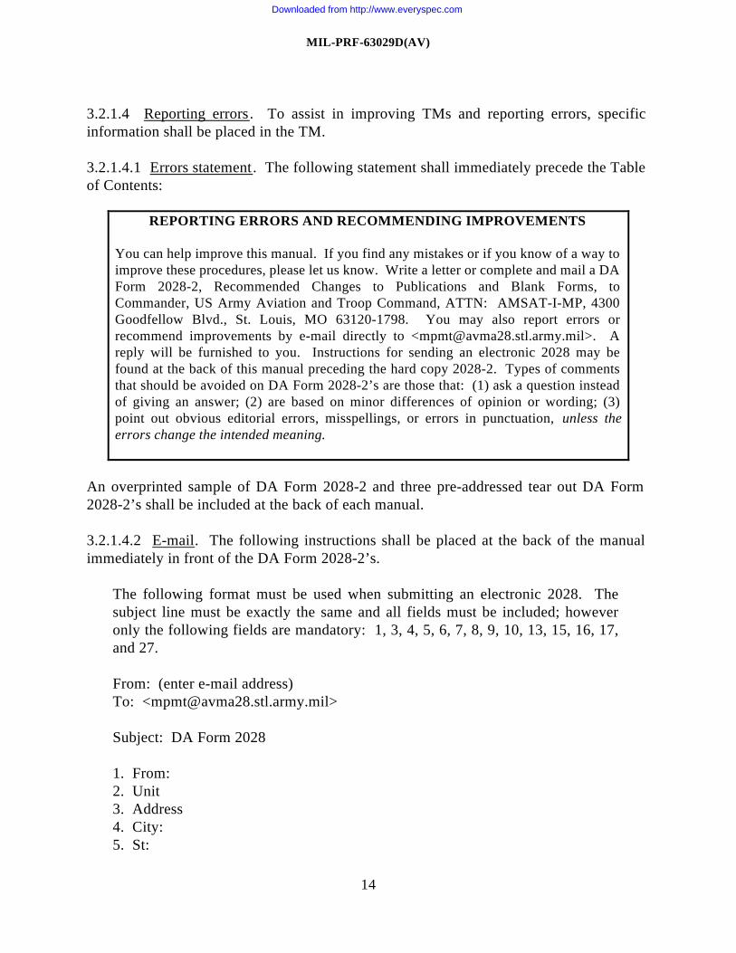
3.2.1.4.1 Errors statement. The following statement shall immediately precede the Tableof Contents:
REPORTING ERRORS AND RECOMMENDING IMPROVEMENTS
You can help improve this manual. If you find any mistakes or if you know of a way toimprove these procedures, please let us know. Write a letter or complete and mail a DAForm 2028-2, Recommended Changes to Publications and Blank Forms, toCommander, US Army Aviation and Troop Command, ATTN: AMSAT-I-MP, 4300Goodfellow Blvd., St. Louis, MO 63120-1798. You may also report errors orrecommend improvements by e-mail directly to <[email protected]>. Areply will be furnished to you. Instructions for sending an electronic 2028 may befound at the back of this manual preceding the hard copy 2028-2. Types of commentsthat should be avoided on DA Form 2028-2’s are those that: (1) ask a question insteadof giving an answer; (2) are based on minor differences of opinion or wording; (3)point out obvious editorial errors, misspellings, or errors in punctuation, unless theerrors change the intended meaning.
An overprinted sample of DA Form 2028-2 and three pre-addressed tear out DA Form2028-2’s shall be included at the back of each manual.
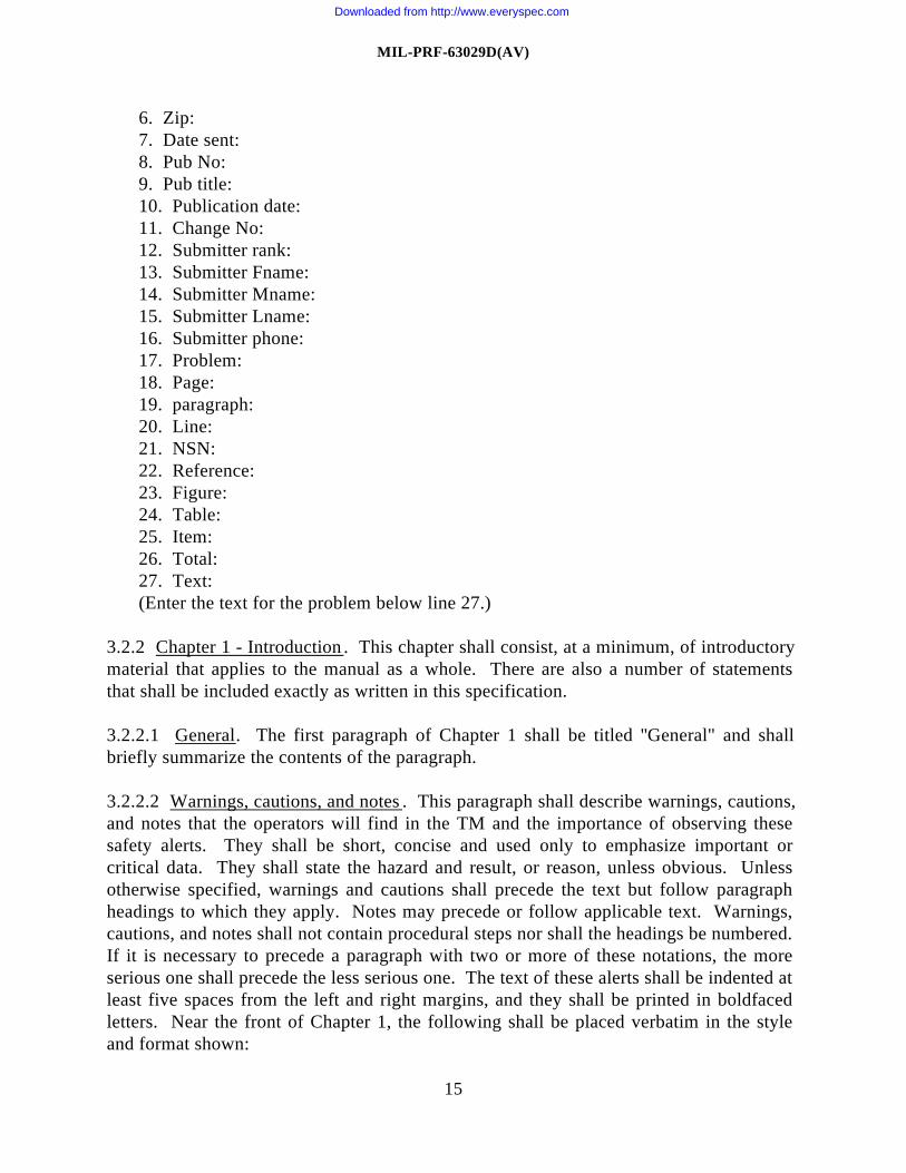
3.2.1.4.2 E-mail. The following instructions shall be placed at the back of the manualimmediately in front of the DA Form 2028-2’s.
The following format must be used when submitting an electronic 2028. Thesubject line must be exactly the same and all fields must be included; howeveronly the following fields are mandatory: 1, 3, 4, 5, 6, 7, 8, 9, 10, 13, 15, 16, 17,and 27.
From: (enter e-mail address)To: <[email protected]>
Subject: DA Form 2028
1. From:2. Unit3. Address4. City:5. St:
Downloaded from http://www.everyspec.com
MIL-PRF-63029D(AV)
15
6. Zip:7. Date sent:8. Pub No:9. Pub title:10. Publication date:11. Change No:12. Submitter rank:13. Submitter Fname:14. Submitter Mname:15. Submitter Lname:16. Submitter phone:17. Problem:18. Page:19. paragraph:20. Line:21. NSN:22. Reference:23. Figure:24. Table:25. Item:26. Total:27. Text:(Enter the text for the problem below line 27.)
3.2.2 Chapter 1 - Introduction . This chapter shall consist, at a minimum, of introductorymaterial that applies to the manual as a whole. There are also a number of statementsthat shall be included exactly as written in this specification.
3.2.2.1 General. The first paragraph of Chapter 1 shall be titled ''General" and shallbriefly summarize the contents of the paragraph.
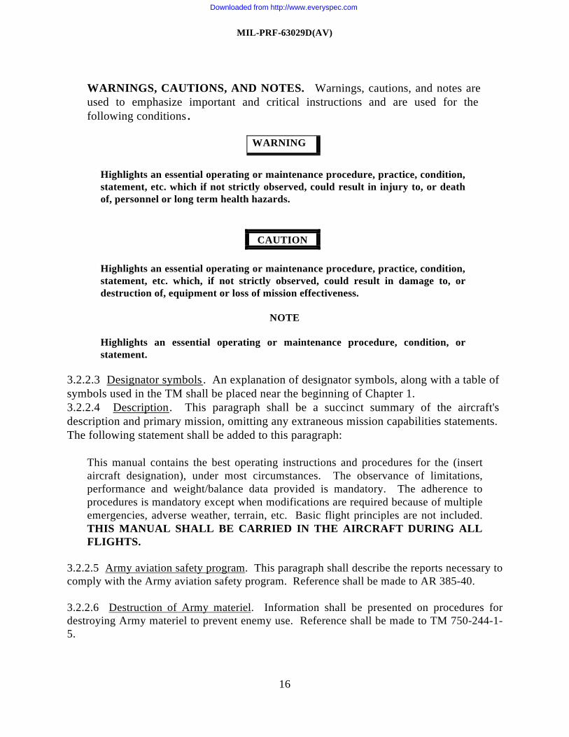
3.2.2.2 Warnings, cautions, and notes . This paragraph shall describe warnings, cautions,and notes that the operators will find in the TM and the importance of observing thesesafety alerts. They shall be short, concise and used only to emphasize important orcritical data. They shall state the hazard and result, or reason, unless obvious. Unlessotherwise specified, warnings and cautions shall precede the text but follow paragraphheadings to which they apply. Notes may precede or follow applicable text. Warnings,cautions, and notes shall not contain procedural steps nor shall the headings be numbered.If it is necessary to precede a paragraph with two or more of these notations, the moreserious one shall precede the less serious one. The text of these alerts shall be indented atleast five spaces from the left and right margins, and they shall be printed in boldfacedletters. Near the front of Chapter 1, the following shall be placed verbatim in the styleand format shown:
Downloaded from http://www.everyspec.com
MIL-PRF-63029D(AV)
16
WARNINGS, CAUTIONS, AND NOTES. Warnings, cautions, and notes areused to emphasize important and critical instructions and are used for thefollowing conditions .
WARNING
Highlights an essential operating or maintenance procedure, practice, condition,statement, etc. which if not strictly observed, could result in injury to, or deathof, personnel or long term health hazards.
CAUTION
Highlights an essential operating or maintenance procedure, practice, condition,statement, etc. which, if not strictly observed, could result in damage to, ordestruction of, equipment or loss of mission effectiveness.
NOTE
Highlights an essential operating or maintenance procedure, condition, orstatement.
3.2.2.3 Designator symbols. An explanation of designator symbols, along with a table ofsymbols used in the TM shall be placed near the beginning of Chapter 1.3.2.2.4 Description. This paragraph shall be a succinct summary of the aircraft'sdescription and primary mission, omitting any extraneous mission capabilities statements.The following statement shall be added to this paragraph:
This manual contains the best operating instructions and procedures for the (insertaircraft designation), under most circumstances. The observance of limitations,performance and weight/balance data provided is mandatory. The adherence toprocedures is mandatory except when modifications are required because of multipleemergencies, adverse weather, terrain, etc. Basic flight principles are not included.THIS MANUAL SHALL BE CARRIED IN THE AIRCRAFT DURING ALLFLIGHTS.
3.2.2.5 Army aviation safety program. This paragraph shall describe the reports necessary tocomply with the Army aviation safety program. Reference shall be made to AR 385-40.
3.2.2.6 Destruction of Army materiel. Information shall be presented on procedures fordestroying Army materiel to prevent enemy use. Reference shall be made to TM 750-244-1-5.
Downloaded from http://www.everyspec.com
MIL-PRF-63029D(AV)
17
3.2.2.7 Forms and records. Flight records and aircraft maintenance records which are usedby the operators and crewmembers shall be described. References shall be made to DA Pam738-751 and TM 55-1500-342-23.
3.2.2.8 Change symbols. The following shall be placed in Chapter 1:
Changes to the text and tables, including new material on added pages shall beindicated by a vertical bar in the outer margin extending close to the entire area of thematerial affected. Pages with emergency markings, which consist of black diagonallines around three edges, shall have the vertical bar or change symbol placed alongthe outer margins between the text and the diagonal lines. Change symbols showcurrent changes only. A miniature pointing hand symbol is used to denote a changeto an illustration. However, a vertical line in the outer margin, rather than miniature pointing hands, shall be utilized when therehave been extensive changes made to an illustration. Change symbols shall not beused to indicate changes in the following.
a. Introductory material.
b. Indexes and tabular data where the change cannot be identified.
c. Correction of minor inaccuracies, such as spelling, punctuation, relocation ofmaterial, etc., unless such correction changes the meaning of instructiveinformation and procedures.
3.2.2.9 Shall, should, and may. The following shall be placed at the end of Chapter 1:
Within this TM use “shall" whenever a TM expresses a mandatory requirement. Use"should" to indicate a non-mandatory but preferred method of accomplishment. Theword “may” shall be used to indicate an acceptable method of accomplishment.
3.2.3 Chapter 2 - Aircraft and Systems Description and Operation.
3.2.3.1 General. This chapter shall describe the airframe and all aircraft systems andcontrols. Each system shall be described under its own heading. The nomenclature of thesystem shall be used as the primary paragraph heading and the name of each control orindicator as the subordinate paragraph heading. The description of each control and item ofequipment shall be brief, concise, and include an index number and figure reference, asappropriate. Include flight crew oriented malfunction isolation charts (Figure 6), as required,and only as approved by the contracting activity (6.2). Maintenance type fault isolation chartsshall not be used.
For aircraft equipped with interactive displays, such as a multifunction display (MFD), thedata management system, including the interactive display, shall be described in this chapter.For each section within this chapter that describes a subsystem, the appropriate top page of
Downloaded from http://www.everyspec.com
MIL-PRF-63029D(AV)
18
the interactive display, including each button, shall be fully described and explained. Inaddition each page underneath the top page shall be briefly described. When needed forclarity, illustrations representative of the pages displayed on the interactive display shall beincluded throughout the TM.
3.2.3.1.1 Controls. Each control contributing to the operation of a system shall be describedand its location given. The function of the control and the end result produced when thecontrol is moved to each of its possible positions shall be included in the description. Anyeffect which this control may have on other systems, or which they may have on the controlshall be stated. If movement of the control requires any special action because of locks, gates,etc., it shall be so stated. When feasible, a separate paragraph and illustration shall be devotedto each control and the name of that control shall be the paragraph heading. It is preferable todivide the control description into two portions, normal controls and emergency controls, ifemergency capabilities exist.
3.2.3.1.2 Indicators. All indicators, instruments, and warning devices which are a part of theaircraft system shall be described and illustrated. This shall include location, function, powersource, and interpretation of the indications.
3.2.3.2 Section I - Aircraft. This section shall provide a complete but concise description ofthe aircraft. At a minimum, the following subjects and illustrations shall be included.
3.2.3.2.1 General. This paragraph shall contain a description of the airframe. Majorassemblies such as fuselage, wings, and tailboom shall be described. Each compartment ofthe aircraft such as cockpits and cabins shall be described and illustrated as required.
3.2.3.2.2 Illustrations and tables. The following illustrations and tables shall be included insection I.
a. The aircraft’s general arrangement shall depict all access openings which will bechecked during preflight of the aircraft (Figure 2). The general arrangement shall beplaced as near to the beginning of Section I as practicable. These diagrams shall notinclude individual controls or aircraft systems. Diagrams which are needed for clarity shallbe used. Two or more of these illustrations, such as crew movement diagram andcompartment diagram, may be combined into one.
b. Figures 7 and 8 illustrate minimum turning radius, ground clearance, dimensions anddanger areas. The minimum turn shall be based on a turn permitted on one wheel (tirehub), with and without power steering assist. Minimum ground clearance shall also beshown.. The turning radius for skid equipped aircraft shall be based on turning the aircrafton an identifiable reference point on the aircraft or an identifiable reference point on theground. An illustration shall be included showing danger areas around the aircraft for allmodes of operations on or near the ground. Areas to be avoided to prevent damage toequipment or injury to personnel shall be depicted or described. These figures shall beprovided for idle and maximum power. For rotary wing aircraft, illustrations shall be
Downloaded from http://www.everyspec.com
MIL-PRF-63029D(AV)
19
based on hover power required at maximum gross weight. Danger areas of main rotors,tail rotors, or propellers shall also be depicted.
c. A table (Figure 9) indicating the most significant differences in design and operationbetween each aircraft series included in the manual shall be provided. Special emphasisshall be placed on features which will affect recognition and operation of the variousseries.
d. Each major compartment, such as cockpit or cabin (Figure 10), that can carry payloador that can be entered by personnel shall be illustrated and identified.
3.2.3.2.3 Landing gear system. Information describing the landing gear system shall bepresented in detail for the operator’s use. The following shall also be included.
a. The steering system, including any special or unusual features, shall be described.
b. The brake system, including all emergency provisions, shall be described. Brakeprovisions for aircraft equipped with floats shall be described as well.
3.2.3.2.4 Instruments, panels and consoles. All instruments, panels, and consoles shall beillustrated. Several configurations may be covered by one illustration labeled typical. Minorvariations in number or type of controls and instruments shall be indicated by detailed viewsto the illustration and by notations in the key. The panels or console may be shown more thanonce when major changes in configuration are involved.
3.2.3.2.5 Canopies. Several configurations may be covered by one illustration labeledtypical. All normal and emergency canopy controls, both external and internal, shall bedescribed and illustrated.
3.2.3.2.6 Doors. All doors to include ramps, hatches, etc., controls for normal andemergency operations, and their sources of power shall be described.
3.2.3.2.7 Seats. Pilot and other flight compartment seat controls shall be described andillustrated. Emergency and ejection seat controls, inertia reels, harnesses, and seat beltsshall be described and illustrated in detail, emphasizing how they are affected by othersystems.
3.2.3.3 Section II - Emergency equipment . All emergency equipment, except that whichforms part of a complete system, shall be included. For example, emergency landinggear controls shall be treated under the landing gear system and emergency fuel pumpsunder the fuel system. Emergency equipment in this section shall include, but not belimited to, hand fire extinguishers, engine fire extinguishers, emergency alarms,pyrotechnic equipment, axes, emergency hatches, signal lamps, ditching jackets, first aidkits, and survival kits. Emergency procedures shall be described only in Chapter 9.
Downloaded from http://www.everyspec.com
MIL-PRF-63029D(AV)
20
Illustrations showing locations of emergency equipment or systems shall be shown asneeded but only in Chapter 9.
3.2.3.4 Section III - Engines and related systems . The engine and its related controls, asoutlined in the following paragraphs shall be described.
3.2.3.4.1 Engines. This paragraph shall cover the most important characteristics andspecial features of the engine. Model designation shall be included for all engines usedin the subject aircraft. The following systems shall be discussed:
a. Cooling system and controls such as cowl flaps and engine cooling fans shall bedescribed.
b. The engine/engine inlet anti-icing/deicing system shall be described and illustrated.
c. The engine fuel control system, which applies to jet and turbine powered aircraftand extends from the engine fuel control unit through the burner ring or combustorsection, shall be described. Where applicable, special emphasis shall be placed on theemergency fuel control systems. Any special or unusual characteristics of the systemshall also be described, but the theory of operation shall not be included. Discussionof the throttle/power lever shall be included, and all systems effected by throttle/powerlever operation shall be mentioned.
d. Information on all controls affecting the oil system shall be included.
e. The ignition system controls shall be described.
f. Starter controls shall be described.g. The infrared suppression system shall be detailed.
h. Engine instruments and indicators shall be described in detail. For the purpose ofthe operator's manual, the fuel and oil supply systems shall be treated as ending at thepoint where they deliver the fluid to the carburetor, fuel control unit, or the engine-driven oil pump.
3.2.3.5 Section IV - Fuel system. This section shall describe the aircraft fuel system asfollows:
3.2.3.5.1 General. A full description of the fuel system shall be given. Coverage ofdrop tank release controls shall be included. Reference shall be made to fuel grades andspecifications in section XV, Servicing.
3.2.3.5.2 Controls and indicators . Fuel system controls and indicators shall be described.
Downloaded from http://www.everyspec.com
MIL-PRF-63029D(AV)
21
3.2.3.5.3 Fuel system management . The fuel system management process shall bedescribed, including auxiliary fuel, booster pump use, fuel transfer procedures, tankselection procedures, and courses of fuel flow. All possible courses of fuel flow, such asinoperative engines and failed boost pump, shall be included. The sequence in whichfuel tanks must be used shall be stated with corresponding reasons (strength or balance).When applicable, reference shall be made to the pertinent portion of Chapter 6 whenweight distribution becomes a problem. The required sequence of use of tanks tomaintain a favorable center-of-gravity (CG) shall be described in detail. Remarks shallalso be included regarding control of the aircraft if the transfer system fails and results inan unbalanced condition because of improper fuel distribution.
3.2.3.5.4 Illustrations. Diagrams of the typical courses of fuel flow, including fuelsystem control positions for takeoff, cruising, landing, and emergency operation shall beincluded.
3.2.3.6 Section V - Flight control system . This section shall cover in detail the flightcontrol system.
3.2.3.6.1 General. This shall describe the flight control system and its location. Thesystem shall be described in its entirety. The nomenclature of the system shall be used asthe primary paragraph heading and the name of each control or indicator as a subordinateheading.
3.2.3.6.2 Flight control system. Flight controls, indicators, trim tabs, force trim, controllocks, etc. shall be discussed as stated in paragraphs 3.2.3.1.1 and 3.2.3.1.2. In addition,all other controls located on the control sticks, wheels, yokes, pedals, cyclic andcollective, shall be mentioned.
3.2.3.6.3 Automatic flight control system . Detailed coverage of automatic stabilizationequipment, stability augmentation control system, and auto pilot shall be provided. Allmodes of operation shall be described. If any additional systems are required to operatein conjunction with the stabilization equipment, a statement shall be included to thateffect. Applicable precautionary data shall be included for conditions of partial ortemporary electrical power failure, manual override, etc. When applicable, referenceshall be made to navigation equipment descriptions and operations contained in Chapter3.
3.2.3.6.4 Illustrations. Illustrations shall be provided for each control column or controlstick. Details shall be shown for switches and control buttons, friction devices, locks,etc. Variations in controls between aircraft series or serial numbers, or both, shall also beshown.
Downloaded from http://www.everyspec.com
MIL-PRF-63029D(AV)
22
3.2.3.7 Section VI - Hydraulic and pneumatic systems . This section shall provide adescription of all hydraulic and pneumatic systems. At a minimum, test switches,indicators and gauges, caution/warning lights, and controls shall be covered:
3.2.3.8 Section VII - Power train system . The power train system shall be described indetail to include the transmission and gearbox systems, drive shafting, system controls,and indicators.
3.2.3.9 Section VIII - Rotors or propellers . Section title shall be "Rotors" or "Propellers"as applicable. Describe the propellers or rotors and their functions. Include a detaileddescription of operation.
3.2.3.10 Section IX - Utility systems . This section shall describe defrosting, anti-icing/deicing, pressurization, oxygen, and rain removal systems and miscellaneousequipment. Coverage here shall be brief and shall concern itself largely with location ofthe equipment and its controls, source of power, illustration of the controls (if notcovered previously), and a brief discussion of function and operation. Control/switchpanels that control several different utility systems should only be illustrated once, iffeasible. The text describing the operation of the different systems should reference thesingle illustration. Information shall be included on all nonmergency equipment which isnot part of a system. All miscellaneous equipment and normal and emergency operationprocedures shall be included. Equipment shall include, but not be limited to, seats (otherthan pilot and flight engineer), hatches, heated blanket provisions, data case, beachinggear, night flying curtains, ladders, relief equipment, food warmers, water containers, andtool kits. Items covered as aircraft loading equipment in Chapter 6 shall not be includedhere. Items dealing with aircraft servicing and ground handling shall be contained insection XV.
3.2.3.11 Section X - Heating, ventilation, cooling, and environmental control systems .This section shall describe the heating, ventilation, cooling, and environmental controlsystems. They shall be covered in paragraphs titled "description", "normal operation",and "emergency operation".3.2.3.12 Section XI - Electrical power supply and distribution systems . The electricalpower supply and distribution systems and controls shall each be described and illustratedunder its own heading (Figure 11). Where pertinent, reference shall be made to auxiliarypower systems that are described elsewhere. The external power source and theinteraction between the auxiliary power plant and the electrical system shall be described.General arrangement and order of the primary system shall be covered first, followed bythe secondary system.
3.2.3.12.1 DC power supply system. DC power supply systems shall include battery;starter-generators, generators, alternators and converters; indicators, gauges, and controls;circuit breaker and junction boxes; auxiliary power; and ground power.
Downloaded from http://www.everyspec.com
MIL-PRF-63029D(AV)
23
Armament. This section shall describe gunnery, rocket, tow target, control, andcomputer equipment and their interrelations when installed. Armor protection shall bediscussed along with the individual item which is being protected. When the equipmentand their description are extensive, armament equipment may be covered as separatesections. The TM shall also cover precautions and safety considerations.
3.2.5.3.1 Armament control system. This part of the manual shall contain the operatinginstructions for the armament control system. Also, information such as presentation onthe scope or sight, when applicable, shall be included. Warm-up time and preflight, in-flight, before landing, and after landing checks shall be listed. Checklist format and styleshall be in accordance with paragraph 3.2.10.2.4.
3.2.5.3.2 Gunnery equipment. Information shall be included on all guns and turrets,including quantity of ammunition which can be carried for each gun. The manual, whendescribing remote controlled turrets, shall include, but not be limited to, the station fromwhich the turret is operated, method of gaining control of the turret, and method oftransferring control. All gunnery controls shall be covered, including gun sight and gunheater.
3.2.5.3.3 Rocket equipment. Information shall be provided regarding the firingprocedures, description and capability, controls, and types and number of rockets that canbe carried. Typical combinations of rockets and firing order shall be covered. Specialprecautions, if any, shall be listed.
3.2.5.3.4 Missiles. Information shall be provided regarding the firing procedures,description and capability, controls, and types and number of missiles that can be carried.Special precautions, if any, shall be listed.
3.2.5.4 Section III - Cargo handling . This section shall describe cargo handling systemsand equipment to include hoists, winches, and cargo hooks.
3.2.5.5 Section IV - Passive defense . Passive defense equipment shall be described,procedures outlined, and controls and precautions listed. Employment methods shall bediscussed.
3.2.5.6 Additional sections. Additional sections may be used as required to describesystems not covered in other sections.
3.2.6 Chapter 5 - Operating Limits and Restrictions .
3.2.6.1 General. This chapter shall include all important operating limits and restrictionsthat shall be observed during ground and flight operations. Special emphasis shall be
Downloaded from http://www.everyspec.com
MIL-PRF-63029D(AV)
24
placed on any unusual restrictions which are particularly characteristic of the aircraft. Alltime limited operations shall include a time limit and the upper and lower boundaries.
3.2.6.2 Section I - General. This section shall contain general information on aircraftlimits and restrictions, including decals and placards. The following statements shall beincluded in the TM:
Purpose. This chapter identifies or refers to all important operating limits andrestrictions that shall be observed during ground and flight operations.
General. The operating limitations set forth in this chapter are the direct results ofdesign analysis, tests, and operating experiences. Compliance with these limits willallow the pilot to safely perform the assigned missions and to derive maximum utilityfrom the aircraft.
Exceeding operational limits. Any time an operational limit is exceeded, anappropriate entry shall be made on DA Form 2408-13-1. Entry shall state what limitor limits were exceeded, range, time beyond limits, and any additional data thatwould aid maintenance personnel in the maintenance action that may be required.
The TM shall list the minimum crew required for flight. The following statement shall beincluded:
The minimum crew required for flight is (fill in proper number). Additionalcrewmembers, as required, will be added at the discretion of the commander inaccordance with pertinent DA regulations.
3.2.6.3 Section II - System limits. This section shall contain all aircraft system limits, notcovered elsewhere in this chapter, that may restrict operation.
3.2.6.3.1 Instrument, interactive display, or display operating ranges and markings. Eachinstrument, interactive display, or display that indicates an operating limit(s) shall beillustrated and accurately reflect the actual markings/displays on the instrument, interactivedisplay, or display (Figure 15). The information appearing on the illustration depictingmarkings or displays shall not be repeated in the text or table. The color codedmarkings/displays or interactive display graphic symbols shall be fully explained. If theinstrument, interactive display, or display limits cannot be adequately explained in thespace provided for the captions, explanations shall be included under the appropriateparagraph heading in this section. The paragraph shall state or describe all limit ranges,including gaps that may be shown in range markings.
3.2.6.3.2 Propeller limitations. Propeller limitations shall be discussed including, but notlimited to reverse pitch and restricted rpm.
Downloaded from http://www.everyspec.com
MIL-PRF-63029D(AV)
25
3.2.6.3.3 Rotor limitations. For rotary wing aircraft, rotor limitations during both flight andground operation shall be discussed, covering such points as restricted rpm, autorational rpm,limitations for startup and shutdown during high winds, and wind gust spread.
3.2.6.3.4 Power limitations. Power limits shall include engine and drive train and idlelimitations. This shall include limitations that must be observed when alternate fuel grades areused. Acceleration limits and restrictions which apply to the engine shall be covered. Limitsshall be expressed in terms of observable indications which are available to the flight crewe.g. 360°C, 46 lb.,10 psi. Terms such as military power or takeoff power should not be used.
3.2.6.3.5 Additional limitations. All system limits and restrictions not described by theinstrument markings shall be included. Limits and restrictions that should be observed whenoperating utility, heating, ventilation, cooling or rain removal systems shall also be included.
3.2.6.4 Section III - Loading limits. Loading limits pertaining to the aircraft shall bediscussed in detail in this section.3.2.6.4.1 Center-of-gravity limitations. Longitudinal limitations shall be described. Laterallimitations shall be described when specified by the contracting activity (6.2). Also, thefollowing statement shall be included:
CG limits for the aircraft to which this manual applies and appropriate charts forcomputation of the CG are contained in Chapter 6.
3.2.6.4.2 Weight limitations. All minimum/maximum aircraft weight limitations includingparking, towing, taxiing, and takeoff and landing from prepared/unprepared fields shall beprovided. For aircraft in which weight distribution is a problem, (such as minimum fuel to becarried in the wings at various gross weights), coverage of the limitations involved shall beincluded. References shall be made to fuel management in Chapter 2, as necessary.
3.2.6.4.3 Turbulence. Restrictions regarding flying in all levels of turbulence shall bediscussed. Limitations shall be covered.
3.2.6.4.4 Other 3.2.3.12.2 AC power supply system. These systems shall include invertersand alternators; indicators, gauges, and controls; AC circuit breaker and junction boxdiagram; auxiliary power; and ground power.
3.2.3.12.3 Breakers. The location of each circuit breaker panel shall be shown, and onstandardized installation, each circuit breaker in the panels shall be identified. The illustrationsha1l depict a typical installation of both systems (AC/DC) which may be combined on oneillustration. In those instances where a standardized circuit breaker location does not exist,the location of circuit breakers or fuses shall be given. This diagram shall be located near thedescription of the electrical system.
3.2.3.13 Section XII - Auxiliary power unit. This section shall include a description of theauxiliary power unit, controls, and its interaction with other systems. Starting, stopping, and
Downloaded from http://www.everyspec.com
MIL-PRF-63029D(AV)
26
in-flight operating procedures shall be contained in Chapter 8 and emergency procedures inChapter 9.
3.2.3.14 Section XIII - Lighting. Information shall be provided for, but not limited to,formation, landing, fuselage, cabin, instruments, wheel well, taxi, navigation, and anti-collision lights. Coverage shall concern itself largely with locations, controls, power sources,and a discussion of functions. Illustrations may be used if equipment is not depicted inChapter 2 or elsewhere.
3.2.3.15 Section XIV - Flight instruments. All flight instruments, indicators, gauges, andmiscellaneous instruments and systems shall be described in this section. Miscellaneousinstruments and systems shall include such items as master caution systems, rpm high/lowwarning systems, trainer instrument panel, and clocks. Special problems, such aserroneous readings of the airspeed indicating system resulting from installation error orhovering, shall be included with references to correction charts, when applicable.Complex display systems shall be included under a separate primary heading.
3.2.3.15.1 Illustrations. Line drawings shall be provided for all instruments. Each indicator,gauge, and control shall be shown (Figure 12). Each item shall be indexed or posted andreferences shall be entered in the text as appropriate. On the drawing the names or indexnumber, whichever is most legible, of the instruments may be placed in the instrument orindicator outline.
3.2.3.16 Section XV - Servicing, parking, and mooring. Servicing shall include, but not belimited to, flight crew oriented instructions for normal and closed circuit refueling and forreplenishment of fuel, oil, hydraulic fluid, other fluids, and air in tires. Servicing shall alsoinclude all other such items involved in servicing the aircraft that a crew could be expected toperform while away from military maintenance support. Safety precautions to observe inservicing a particular tank or reservoir, such as grounding and prevention of fire hazards, shallbe stated clearly. Servicing instructions shall be supplemented with a diagram showinglocations of regular and alternate servicing points. NO STEP areas on walkways leading totanks shall be indicated, with necessary precautions. Reference shall be made to graphs ordata in other parts of the manual pertinent to servicing, such as tire pressure versus grosstakeoff weight.
3.2.3.16.1 Servicing diagram. The servicing diagram shall depict each servicing point,including, but not limited to, tanks, reservoirs, filler caps, receptacles, oxygen bottles, andaccumulators and shall be shown as viewed (Figure 13). Illustrations of site gauges and otherindicators shall clearly depict proper servicing levels.
3.2.3.16.2 Servicing table. The servicing table shall be in tabular form as shown in Figure14. Each item of equipment including, but not limited to, engine, transmission, gearboxes,reservoirs (hydraulic, anti-icing), auxiliary power unit, and oxygen systems shall be listedunder "System". Under the heading of "Specification", the military specification for the fuel,oil, fluid, or lubricant shall be listed including references to any notes on temperature ranges,
Downloaded from http://www.everyspec.com
MIL-PRF-63029D(AV)
27
mixing of oil, etc. Fuel capacities shall also be listed to include total, servicing capacity, andusable capacity in U.S. measurements to the nearest tenth of a gallon, and metric equivalents.
3.2.3.16.3 Approved fuels. Include a tabular listing of primary, alternate, and emergencyfuels, to include NATO and commercial brand names authorized for use in the aircraft forwhich this manual applies. Warnings and cautions regarding additives shall be presented inthe table. Also restrictions on the use of any fuels shall be stated. The fuels contained in thislisting shall only be those authorized for use by TB 55-9150-200-24 and by the contractingactivity (6.2). This information shall not be repeated in the manual.
3.2.3.16.4 Additional servicing instructions. Information shall include a listing of acceptablecommercial engine oils as indicated in TB 55-9150-200-24 and as authorized for use in theaircraft (Figure 15).
3.2.3.16.5 Ground handling. List instructions and necessary precautions for ground handlingaircraft, including any information needed in extreme cold, heat, humidity, and dust. Providedescription and instructions for operating any ground handling equipment involved. Left andright turning limits while towing (with or without external stores) shall be listed. Aircraftground handling procedures relating to electronics equipment shall be stated when applicable.
3.2.3.16.6 Parking and mooring. Instructions for parking and mooring and the installationand stowage of aircraft covers, control locks, chocks, and tiedown devices shall be describedand illustrated. Ground handling, parking, and mooring may be shown on a single pageillustration.
3.2.4 Chapter 3 - Avionics.
3.2.4.1 General. Except for mission avionics, this chapter shall describe the avionicsequipment configuration including all its systems and controls and shall provide the propertechniques and procedures to be employed when operating the equipment.
3.2.4.2 Section I - General. This chapter shall cover avionics equipment configurationsinstalled on a specific aircraft. It shall include a brief description of the avionics equipment,its technical characteristics, capabilities, and locations. Reference shall be made to Chapter 4for mission avionics.
For each item of avionics equipment contained within Sections II, III, and IV, the TM shall bewritten in the following format.
a. Description
b. Controls and functions
c. Operation
Downloaded from http://www.everyspec.com
MIL-PRF-63029D(AV)
28
d. Emergency operation (if applicable)
Additional sections may be added to this chapter by the contracting activity (6.2).
3.2.4.2.1 Description. Avionics equipment shall be described in detail, including controls,indicators, instruments (if applicable), jacks, switches, control panels, etc. Antenna locationsshall be shown on appropriate illustrations.
3.2.4.2.2 Controls and functions.
a. The location and function of each control, including built-in test capability, contributingto the operation of the avionics equipment shall be listed. A separate paragraph shall beused for each control panel. Reference shall be made to illustrations in Chapter 2regarding controls and control panels.
b. A tabular listing shall be included with each paragraph listing control panels. Thelisting shall be divided into two columns, titled "Control” and “Function" or"Control/Indicator” and “Function", whichever is applicable. Each control or indicatorshall be listed and its function defined in terms of what the operator of the control will see,hear, or do as a result of the control setting. Terms of simple, immediate, and observableresults shall be used. No attempt shall be made to give the operator the exact technicaldetails about what happens when the control is used.
3.2.4.2.3. Operation. A series of paragraphs shall be used to describe the operating detailsfor each item of avionics equipment. Whenever standard operational avionics data existswithin the government, such data shall be furnished to the contractor by the contractingactivity. Complete operating procedures shall be included as follows:
a. When separate modes of operation are available i.e. when the equipment may serve twoor more systems, each mode shall be described. These shall be listed as modes ofoperation and each shall be briefly described.
b. Explain the sequence of settings and the position to which the controls should be set toensure proper results each time the equipment is energized. Instructions shall be providedto prevent the possibility of damage through improper settings or sequence of operations.When appropriate, call attention to operating tolerances. When operation of a unit isrelated to or dependent on the operation of a similar or independent control unit, thisinformation shall be included in the operating procedure. Only those controls normallyused by the operator shall be included. Control adjustments that are the responsibility ofmaintenance personnel shall not be included.
c. If the configuration provides for a parallel operation from various positions in theaircraft, similar, separate, and complete coverage for each position shall be provided.When the procedure is identical to a position previously covered, it may be covered by areference to the previous procedure.
Downloaded from http://www.everyspec.com
MIL-PRF-63029D(AV)
29
3.2.4.2.4 Emergency operations. When applicable, settings and operations of avionicsequipment during emergency operations shall be described.
3.2.4.2.5 Power source. A brief description of the power sources for avionics equipmentshall be provided, including any special procedures or limitations using, but not limited to,external power and battery power.
3.2.4.3 Section II - Communications. This section shall contain all information forcommunications equipment installed in the aircraft.
3.2.4.4 Section III - Navigation. This section shall cover all navigation systems andindicators, as applicable. When there is doubt as to whether the system should be coveredunder communications or navigation, the primary use of the system shall be the decidingfactor, and a suitable reference shall be made in the manual to aid the operator in locating thematerial. The following systems and indicators shall be described.
a. Automatic direction finder (ADF)
b. Gyro compass and magnetic indicators
c. Marker beacon
d. Flight director
e. (VHF) OMNI directional range
f. Tactical Air Navigation (TACAN)
g: Instrument landing system
h. Doppler
i. Inertial navigation system (INS)
j. Autopilot
k. Other
3.2.4.5 Section IV - Transponder and radar. This section shall cover all transponders,collision warning systems, and radar systems and indicators, as applicable.
3.2.5 Chapter 4 - Mission Equipment.
Downloaded from http://www.everyspec.com
MIL-PRF-63029D(AV)
30
3.2.5.1 General. This chapter shall describe all standard mission equipment that may beutilized with the aircraft. Coverage shall include description, controls and function, operatingprocedures, power sources, and illustrations. Controls, functions, and operating proceduresshall be in the same format as Chapter 3.
3.2.5.2 Section I - Mission avionics. This section shall contain unclassified informationregarding mission avionics equipment that is not a part of the standard flight communication,navigation, transponder, or radar equipment. It contains electronic equipment such as radiomonitoring systems, side looking airborne radar (SLAR), infrared devices, and photographicequipment. Detailed information shall be given regarding the photographic equipment,including, but not limited to, types of cameras, control stations, camera doors, and capabilitiesof the equipment. Gun camera equipment shall also be covered. Mission avionics equipmentthat requires extensive explanation of operating procedures shall be covered in this section orin an appendix. An appendix for mission avionics equipment shall be included only ifauthorized by the contracting activity (6.2). Classified information on mission avionicsequipment shall be covered in a separate classified supplement to the manual.
3.2.5.3 Section II - limitations. Other types of limitations that affect operations shall becovered, including:
a. Additional restrictions to be observed when carrying stores. For aircraft equipped tocarry a variety of external stores, information concerning the stores carried at each stationand the maximum lateral unbalanced load that can be carried shall be included.
b. Limitations as to the weight for external sling loads on rotary wing aircraft and speedrestrictions, if any.
c. Floor loading limits which are to be observed when carrying internal cargo.
d. Restrictions on jettisoning external stores and sling loads.
3.2.6.5 Section IV - Maximum and minimum airspeed limits. Airspeed limitations shall bediscussed, including level flight airspeed, diving airspeed, airspeed for various degrees of flapextension, airspeed for various stabilator positions, airspeed for door opening, and airspeedsunder various conditions of weight and configuration. For rotary wing aircraft, sideward andrearward airspeed limits and restrictions shall be discussed. Airspeeds shall be expressed asknots indicated airspeed (KIAS), unless otherwise specified by the contracting activity (6.2).
3.2.6.5.1 Airspeed operating limits chart. This chart shall present operating limits forforward flight at various gross weights, pressure altitudes, free air temperature (FAT), andKIAS (Figure 16).
3.2.6.6 Section V - Maneuvering limits. Maneuvering flight limitations to include acrobaticflight, if applicable, shall be described. Acceleration limitations shall also be covered,including maximum acceleration with tip tanks and maximum bank angle at high gross
Downloaded from http://www.everyspec.com
MIL-PRF-63029D(AV)
31
weight. Maximum permissible accelerations under various flight conditions at specific grossweights and fuel weights shall be detailed. For aircraft not equipped with G meters, G forcesshall be expressed in terms that are recognizable by the pilot, such as airspeed and bank angle.Restrictions on control movements shall be listed. Material shall be presented on permissiblebank angles and side slip. Prohibited maneuvers shall be listed as appropriate.
3.2.6.6.1 Flight envelope chart. For aircraft with G meters, plots of load factor versus speedfor the full range of gross weight shall be shown. The speeds at which maneuvers arerestricted and unrestricted, as a function of load limit factors, shall be presented (Figure 17).When changes in configuration result in variations in airspeed position error, separateairspeed scales shall be shown. Where direct reading Mach meters are provided, charts forboth indicated airspeed (IAS) and indicated Mach number (IMN) shall be provided.
3.2.6.7 Section VI - Environmental restrictions. This section shall cover altitude,temperature, rain, snow, ice, hail, and oxygen limits, as applicable. Material on maximumwind velocity and gust spread, maximum wind velocity for crosswind operations, wind fromthe critical azimuth, and normal operation shall be included. Operations under wind azimuthdirection and wind velocity conditions which should be avoided shall be discussed. Whereappropriate, charts shall be used to depict the preceding conditions.
3.2.6.7.1 Flight under instrument meteorological conditions (IMC). The TM shall defineIMC and provide criteria for such flights. In addition when applicable, the TM shall notewhen a particular aircraft is qualified for operation in instrument meteorological conditionsand when a certain aircraft is restricted to visual flight conditions.
3.2.6.8 Additional sections. Additional sections may be used to allow for added limits orrestrictions to fit specific aircraft when specified by the contracting activity (6.2).
3.2.7 Chapter 6 - Weight/balance and loading
3.2.7.1 Section I - General. This section shall contain general statements about theimportance of weight and balance calculations. It shall also note that Chapter 6 containssufficient instructions and data so that an aviator, given the proper data, can compute anycombination of weight and balance. When weight and balance computers/calculators areprovided for the aircraft, instructions and examples of their use shall be based on gear downconfigurations, with supplementary data for gear up conditions (when required). Thefollowing statement shall be included:
Army (insert assigned aircraft designation) are in class (insert class). Additionaldirectives governing weight and balance of class (insert class) aircraft forms andrecords are contained in AR 95-1.
3.2.7.1.1 Aircraft compartment and station diagram. This paragraph and diagram shallprovide a general description of the aircraft compartments and shall show the reference datumline, stations, butt lines, and water lines in inches (Figure 18).
Downloaded from http://www.everyspec.com
MIL-PRF-63029D(AV)
32
3.2.7.2 Section II - Weight and balance. This section shall contain information necessary forthe computation of weight and balance for loading of specific aircraft. Instructions forcompletion of weight and balance forms (DD Form 365 series) shall not be provided in themanual; however, TM 55-1500-342-23 which provides these instructions shall be referenced.Sufficient information shall be provided in this section to permit the flight crew to readily usethe data presented in the other sections of this chapter to determine loading arrangements, fuelburn or transfer sequences, ordinance off-load sequences, and other weight and balanceprocedures to assure the aircraft remains within weight and balance limits for the entire flight.
3.2.7.3 Section III - Fuel/oil. Fuel quantity data shall be in chart form (Figure 19). Thenames of the tanks on the charts shall be identical to the name appearing on the tank selector(a more explanatory title may be carried in parentheses if desired). Any group of tanks orcells which are interconnected to fill and drain shall be treated as a single tank. The chartshall include data on each tank (including droppable and ferry) that is designed for use withthe aircraft. Tank volume shall be given in terms of usable fuel rather than total tank volume.Fuel quantities shall be given in gallons regardless of the type of instrumentation. All gallonfigures shall be followed by the conversion to pounds. The grid lines within the chart shall bebased on fuel weight in pounds of fuel. It shall be stated that the weights are based on a givenspecific gravity at standard day temperature.
3.2.7.3.1 Oil data. When specified by the contracting activity (6.2), a statement of usable oilcapacity, equivalent in pounds, total moments, and fuselage station number shall be includedin the manual. Aircraft that have a large usable oil capacity shall have a tabular listing if oilloading computation is critical. It shall be noted in the TM that the weight shall be based onspecific gravity at standard day temperature.
3.2.7.4 Section IV - Personnel. This section shall contain all essential information andinstructions for preparation, loading, and unloading of personnel, including airborne troops.
3.2.7.4.1 Personnel compartment and entrances. A general description of the personnelcompartment and entrances, including profile and cross-section drawings showing alldimensions, in inches, shall be provided. In addition, a description shall be provided of anycritical dimensions which limit full use of the personnel compartment.
3.2.7.4.2 Personnel loading and unloading. Personnel loading and unloading shall include,but not be limited to, a checklist and description of steps necessary for loading and unloadingtroops as follows:
a. Troop seat installation
b. A description and operation of safety belts and harnessesc. A check of comfort and emergency provisions
d. Instructions for troop loading and unloading procedure
Downloaded from http://www.everyspec.com
MIL-PRF-63029D(AV)
33
3.2.7.4.3 Personnel weight. The TM shall note that when aircraft are operated at criticalgross weights, the exact weight of each individual occupant plus equipment should be used.In addition the TM shall state that if weighing facilities are not available, or if the tacticalsituation dictates otherwise, loads shall be computed as follows:
a. Combat equipped soldiers - 240 pounds per individual.
b. Combat equipped paratroopers - 260 pounds per individual.
c. Litter and patients weight - 265 pounds per patient.
d. Crew and passengers with no equipment - compute weight according to eachindividual's estimate.
3.2.7.4.4 Personnel moments. Personnel moments charts for personnel in any position shallbe provided (Figure 20).
3.2.7.5 Section V - Mission equipment. Loading data charts for mission equipment shallprovide a tabular listing containing the quantity, weight and moment of each load item up tothe maximum quantity for which provisions are available. Only items of load (Chart E items)shall be listed. Items which are part of the basic weight (Chart A Items) shall not be part ofthis listing. Data shall be provided for all applicable mission system loads including, but notlimited to, armament, avionics, sling, hoist, and litters. Listings shall provide weights andmoments of required pylons and launchers. Tabular listing of rockets shall be inclusive formaximum capacity of launchers. Since rockets vary in weight by type, separate listings shallbe required (Figure 21).
3.2.7.6 Section VI - Cargo loading. This section shall contain detailed information on cargoloading.
3.2.7.6.1 Description and illustrations. A general description of cargo compartment andentrances, including profile and cross-section drawings showing all dimensions (in inches)shall be provided. Also, descriptions of critical dimensions which limit full use of cargocompartment shall be included.
a. A plan view showing dimensions of cargo floor, designation, location, and strength oftie-down fittings, diagram and limitations on use of fittings, including the desirable cone ofaction when using fittings, shall be provided. Also, a plan view of cargo floor showingvariations in floor strength and weight concentration limitations in various areas shall beincluded, as applicable.
b. A suitable view of litter provisions showing location shall be presented.
c. A general description of, and operating instructions for, aerial delivery systems shall beincluded, when applicable.
Downloaded from http://www.everyspec.com
MIL-PRF-63029D(AV)
34
d. A list and description of all cargo loading aids, unloading aids, cargo securingequipment (including, but not limited to, ramps, hoists, winching provisions, andtiedowns), and stowage provisions shall be presented.
3.2.7.6.2 Equipment loading and unloading. This shall include procedures and a checklistfor loading and unloading vehicles and equipment as follows:
a. Assembly of equipment needed for loading.
b. Preparation of cargo compartment and floor and installation of fittings.
c. When applicable, preparation of the aerial delivery system.
d. Including, but not limited to, operation of cargo doors, ramps, load assist devices, andaircraft support jacks, including installation and operation, as applicable. Instructions forchecking landing gear shall be included, when appropriate.
e. Assembly and checking of unloading aids and releasing of cargo tiedown devices.
3.2.7.6.3 Preparation of general cargo. Pre-loading information shall be presented asfollows:
a. The TM shall note that loading personnel should assemble, prior to loading, data suchas weights, dimensions, CG locations, and contact areas of equipment for use inpositioning the load.
b. Reference shall be made to the weight and balance computations in Section II, and thebalance computer, if furnished, for the computation of final load positions in the aircraft.
3.2.7.6.4 Loading, securing, and unloading cargo. This portion of the TM shall includegeneral methods of loading, safe lashing, and unloading of cargo, vehicles, and equipment.Rigging of cargo for aerial delivery shall be included, when applicable. The information shallbe detailed enough to acquaint service personnel with the factors involved in properlyloading, securing loads, and unloading the aircraft.
3.2.7.6.5 Cargo center-of-gravity. A chart shall be provided (Figure 22) showingapproximate allowable cargo CGs versus known weights which may be used for planningpurposes for various cargo loads. The chart shall be based on a range of aircraft basic weightsand center of gravity locations to allow for anticipated variations in these values. The chartshall state that this data is for planning purposes only, that the results are approximate, andfinal loading must be checked for the particular aircraft using weight and balancecomputations and the balance computer, if furnished.
Downloaded from http://www.everyspec.com
MIL-PRF-63029D(AV)
35
3.2.7.6.6 Loading procedure. This shall include a checklist of the actions required from thetime the aircraft is prepared for loading until it is ready for flight. It shall include instructionsand notes on loading equipment into the aircraft, checking items with CG markings and items10 feet or longer and placing them in position, determining the amount of shoring required forflight conditions, and general instructions for loading and lashing miscellaneous cargo.Reference shall be made to the appropriate regulations regarding handling of hazardousequipment.
3.2.7.6.7 Securing loads. The following items shall be described in the TM.
a. Approved restraint criteria including fore, aft, sideward and vertical restraints.
b. Detailed tiedown instructions shall be provided only for equipment or cargo that areunique to a specific aircraft.
3.2.7.6.8 Unloading procedures. Procedures for unloading the aircraft and stowingassociated equipment shall be listed.
3.2.7.7 Section VII - Center-of-gravity. This section shall cover longitudinal CG limitations.Lateral CG limits shall be shown as specified by the contracting activity (6.2).
a. Where possible, the gross weight and CG limitations of the aircraft shall appear on asingle chart; however, additional charts may be used if necessary to adequately portray thevarious configurations of the aircraft. All charts shall be in the style and format of Figure23.
b. Explanatory text shall explain the purpose and components of the charts; illustrate theuse of the charts; emphasize that charts are designed to illustrate degree of risk involved atvarious weights and CGs; and establish limitations.
c. The chart shall be based on gross weight which is defined as the total weight of theaircraft and its contents. It shall include, but not be limited to, operating weight plus fuel,cargo, ammunition, missiles, and external auxiliary fuel tanks. The gross weight in poundsshall be shown on the left side of the chart, and shall range from the aircraft's minimumoperating weight to maximum gross weight allowable.
d. The TM shall present at least one example to illustrate the application of the chart.
3.2.8 Chapter 7 - Performance Data.
3.2.8.1 General. This chapter shall contain all the performance data charts required for thecompletion of preflight and in-flight mission planning. The data presented shall cover themaximum range of conditions and performances for which the aircraft is qualified.Explanatory text applicable to the use of data presented shall be included for each model ofaircraft. Performance data charts shall appear in all TMs, including the initial issue.
Downloaded from http://www.everyspec.com
MIL-PRF-63029D(AV)
36
Information contained on the charts shall be based on, and shall be consistent with, therecommended operating procedures and techniques set forth elsewhere in the manual. Eachsection in the chapter shall include an explanation of all applicable charts and a synopsis ofpertinent terms used with each chart.
3.2.8.1.1 Data basis. Unless otherwise specified by the contracting activity (6.2), thepreparation of performance data charts shall be derived from flight test reports, whenavailable. Exceptions to this may be authorized by the contracting activity for new aircraft,provided adequate flight tests have been completed for the prototype. However, for theseexceptions, an evaluation of all changes which affect performance shall be obtained byadditional flight tests. The basis for data presented shall be clearly defined at the bottom ofeach chart to include data type and source data document. Army test reports shall be usedwhen available. When flight test reports are not available, referenced estimates shall beclearly identified as such. Conservative estimates shall be used until verified by flight testdata. Data that is not based strictly on the particular aircraft shall be explained in detail. Theresults of Government reports shall be referenced and used in preference to flight test dataobtained by contractors.
3.2.8.1.2 Identification. Each chart shall be marked in the following manner:
a. Titles shall be centered above the chart. The name of each chart shall define the type ofinformation to be obtained from that particular chart.
b. Condition headings (3.1.23.2.2) shall be centered below the title and, when required,shall contain the following types of information, when applicable:
(1) Pressure altitude
(2) Situation to which chart applies (e.g. takeoff, landing, sling load takeoff, etc.)
(3) Conditions of auxiliary equipment (ECU, bleed air, etc.)
(4) Configuration
(5) Wing flap position
(6) Rotor or prop rpm
(7) Engine rpm
(8) Fuel type
(9) Hovering condition (in ground effect (IGE) or out of ground effect (OGE))
(10) Power requirements
Downloaded from http://www.everyspec.com
MIL-PRF-63029D(AV)
37
(11) Runway conditions
(12) Wind conditions
(13) Gear up/down
(14) Power required
c. Titles of figures shall be centered below all chart information and shall match the titleshown at the top of each chart.
3.2.8.1.3 Factors affecting data. Conditions which affect the data but are not presented asvariables on any specific chart shall be listed as “Conditions” under the title of the chart. Anexplanation of these factors shall be included in the text that describes that chart.
3.2.8.1.4 Configuration. Unless otherwise specified by the contracting activity (6.2), thebaseline configuration for all presented data shall be the most probable combat configuration.This baseline configuration shall be labeled and presented as a condition on applicable charts.The baseline configuration shall be completely defined in the "Drag" section. Where inherentconfiguration variations exist (including, but not limited to, antenna variations, IRsuppressers, and engine inlet configurations), the data shall be based on the most conservativeconfiguration combination (highest drag, lowest power/thrust available, highest fuelconsumption, etc.). The effects of altering these items shall be discussed in each section, asapplicable.
3.2.8.1.5 Fuel. All charts shall be based on the primary fuel for the engine/engines installedunless additional charts are required by the contracting activity for alternate fuels (6.2).
3.2.8.1.6 Atmospheric conditions. Where data is presented incrementally, it shall bepresented to the next increment beyond the range of probable operating atmosphericconditions as found in MIL-STD-210, to permit interpolation. Unless otherwise specified bythe contracting activity (6.2), standard day, standard conditions, standard temperature, ordensity altitude shall not be mentioned or presented. The following formulas for convertingpressure altitude(Hp) to static air pressure (P), and visa versa, shall be used:
P (in. Hg) = 29.92125(1−Hp/145,442.1)5.255376
Hp (ft.) = 145,442.1(1−P/29.92125).1902632
3.2.8.1.7 Allowances. Allowance shall be made for all installation losses and a completeanalysis of such allowances shall be included in the performance data substantiation report.The following allowances shall be included. An increased allowance of five percent shall bemade for fuel consumption data only when data is based on estimates; however, this shall notbe stated in the TM.
Downloaded from http://www.everyspec.com
MIL-PRF-63029D(AV)
38
3.2.8.1.8 Limitations and restrictions. Applicable operating limits shall be shown. Restrictedoperating regions shall be depicted by shaded areas. Data may be extended to the nextnormal increment beyond operating limits to aid interpolation. Such data shall be representedby dotted lines. Note: maximum gross weight is an operating limit.
3.2.8.1.9 Definitions. Definition of terms used through this chapter including, but not limitedto, takeoff speed, takeoff distance, and rotation speed shall be included in Appendix B.
3.2.8.1.10 Rotary wing performance data. Unless otherwise specified by the contractingactivity (6.2), the following performance data charts shall be created for rotary wing aircraft:
a. Fuel flow (Figure 24)
b. Maximum torque available (insert condition/time) (Figure 25)
c. Hover (Figure 26)
d. Takeoff (Figure 27)
e. Drag (Figure 28)
f. Cruise (Figure 29)
g. Climb-decent (Figure 30)
h. Airspeed calibration (Figures 31 and 32)
Additional charts peculiar to certain aircraft, such as multi-engine, shall be included asspecified by the contracting activity. These charts, if required, shall completely define theoperation or restrictions of the aircraft.
3.2.8.1.11 Fixed wing performance data. Unless otherwise specified by the contractingactivity (6.2), the following performance data shall be presented for fixed wing aircraft:
a. Crosswinds - takeoff and landing (Figure 33)
b. Idle fuel flow (Figure 24)
c. Torque available for takeoff (Figure 34)
d. Takeoff - normal (Figure 35)e. Normal rotation/takeoff airspeed (Figure 36)
f. Acceleration check distance (Figure 37)
Downloaded from http://www.everyspec.com
MIL-PRF-63029D(AV)
39
g. Accelerate-stop distance (Figure 38)
h. Accelerate after lift off (Figure 39)i. Minimum single engine control airspeed (Figure 40) (flaps down and up, if applicable)
j. Single engine climb (Figure 41).
k. Cruise climb (Figure 42)
l. Drag (Figure 28)
m. Cruise (Figure 44)
n. Climb/descent (Figure 43)
o. Approach speed (Figure 45)
p. Landing (Figure 46)
q. Airspeed calibration (Figures 31 and 32)
3.2.8.2 Section I - Introduction. This section shall contain an explanation of the performancedata to include the purpose, scope, limits, uses, and conditions.
3.2.8.2.1 Purpose. This paragraph shall include the following:
The purpose of this chapter is to provide the best available performance data for the(insert assigned aircraft designation). Regular use of this information will allow youto receive maximum safe use of the aircraft. Although maximum performance is notalways required, regular use of this chapter is recommended for the followingreasons:
a. Knowledge of performance margins will allow you to make better decisionswhen unexpected conditions or alternate missions are encountered.
b. Situations requiring maximum performance will be more readily recognized.
c. Familiarity with the data will allow performance to be computed more easilyand quickly.
d. Experience will be gained in accurately estimating the effects of conditionsfor which data are not presented.
Downloaded from http://www.everyspec.com
MIL-PRF-63029D(AV)
40
The information is primarily intended for mission planning and is most useful whenplanning operations in unfamiliar areas or at extreme conditions. The data may alsobe used inflight, to establish unit or area SOPs, including pilot aid cards, and toinform ground commanders of performance/risk tradeoffs.
3.2.8.2.2 General. This paragraph shall contain the following:
The data presented covers the maximum range of conditions and performance thatcan reasonably be expected. In each area of performance, the effects of altitude,temperature, gross weight, and other parameters relating to that phase of flight arepresented. In addition to the presented data, judgment and experience will benecessary to accurately determine performance under a given set of circumstances.The conditions for the data are listed under the title of each chart. The effects ofdifferent conditions are discussed in the text accompanying each phase ofperformance. Where practical, data are presented at conservative conditions.However, no general conservatism has been applied.
CAUTION
Exceeding operating limits can cause permanent damage to critical components.Overlimit operation can decrease performance, cause immediate failure, orfailure on a subsequent flight.
3.2.8.2.3 Limits. The following statement shall be placed verbatim in the TM:
Applicable limits are shown on the charts. Performance generally deterioratesrapidly beyond limits. If limits are exceeded, minimize the amount and time. Enterthe maximum value and time beyond limits on DA Form 2408-13-1 so propermaintenance action can be taken. Exceeding operating limits can cause permanentdamage to critical components. Overlimit operations can decrease performance,cause immediate failure, or failure on a subsequent flight.
3.2.8.2.4 Use of charts. A sample problem typical of a normal mission accomplished by theaircraft shall be included on the first chart of the section and/or on the preceding page.Additional examples may be prepared as required for other charts within a section. Whenpossible, actual chart values shall be used throughout the problem. Data for the problem inwhich derivation may not be entirely clear shall be explained. Additional discussion, sampleproblems, or illustrations may be used throughout the chapter to clarify the usage of charts.
The TM shall point out that the use of a straight edge (ruler or page edge) and a hard finepoint pencil is recommended to avoid cumulative errors. In addition to the primary use, otheruses of each chart are explained in the text accompanying each set of performance charts. Anexample of an auxiliary use of the charts is shown by noting that although the hover chart isprimarily arranged to find torque required, maximum skid height or maximum gross weight
Downloaded from http://www.everyspec.com
MIL-PRF-63029D(AV)
41
can also be found. The TM shall note that in general, any single variable can be found if allother variables are known. Also, the tradeoffs between two variables can be found.
3.2.8.2.5 Data basis. This paragraph shall contain the following statements and definitions:
The source of data used is indicated at the bottom of each performance chart under“Data Basis”. The applicable report and date of the data are also given. The dataprovided generally are based on one of the following categories.
a. Flight test data is obtained by flight tests of the aircraft at precisely knownconditions using sensitive calibrated instruments.
b. Calculated data is data based on tests, but not on flight tests of the completeaircraft.
c. Estimated data is data based on estimates using aerodynamic theory or othermeans not verified by flight testing.
3.2.8.2.6 Specific conditions. This paragraph shall contain the following:
The data presented is accurate only for specific conditions listed under the title ofeach chart. Variables for which data is not presented, but which may affect thatphase of performance, are discussed in the text. Where data is available orreasonable estimates can be made, the amount that each variable affects performanceshall be given.
3.2.8.2.7 General conditions. General conditions, in addition to specific conditions listed oneach chart, shall be included in the text of the TM. Examples of general conditions whichmight affect performance of the aircraft include, but are not limited to, rigging, pilottechnique, sideslip, aircraft variation, engine variation, and instrument variation. Informationshall be included which defines what effect the general conditions listed will have on theperformance data of the aircraft.
3.2.8.2.8 Performance discrepancies. The following shall be included in the TM:
Regular use of this chapter will also allow monitoring of instruments and otheraircraft systems for malfunctions, by comparing actual performance with plannedperformance. Knowledge will also be gained concerning the effects of variables forwhich data is not provided, thereby increasing the accuracy of performancepredictions.
3.2.8.3 Section II and subsequent sections. A separate section shall be created for each chartlisted in paragraphs 3.2.8.1.10 and 3.2.8.1.11. The sections shall be titled as described in thetwo paragraphs. In addition to the chart itself, each section shall contain, as a minimum, thefollowing requirements:
Downloaded from http://www.everyspec.com
MIL-PRF-63029D(AV)
42
a. Description. The paragraph shall provide a description of the performance datapresented in each applicable section to include those parameters obtainable from the chartand information relative to any peculiarity of data presented.
b. Use of charts. Reference shall be made to examples used on each chart. Additional useof charts my be included when approved by the contracting activity (6.2). Reference shallbe made to related charts which may be used in conjunction with the chart and allinformation relative to peculiarities of data presented on the chart.
c. Conditions. Each condition which has a direct or indirect effect on the chart datapresented, shall be discussed, explaining the effect it may have on the aircraft.
3.2.8.3.1 Rotary wing chart content. Performance data charts for rotary wing aircraft shallconform to the requirements detailed in the following paragraphs.
3.2.8.3.1.1 Fuel flow chart. The fuel flow chart (Figure 24) shall show fuel flow at both theairframe idle throttle position and at normal rotor speed with flat pitch. The chart shall alsopresent fuel flow conditions when the engine is operational at different configurations, e.g.bleed air On/Off. Pressure altitude and FAT shall be used as the criteria for fuel flowcomputations. Reference shall be made to other charts within the chapter that present fuelflow data at cruise conditions. Fuel flow data shall be based on the primary fuel type.Information shall be included in the supporting text to define additional pertinent informationwhich may affect fuel flow. All data shall be based on normal operating engine rpm.
3.2.8.3.1.2 Maximum torque available chart. The charts for maximum torque available(Figure 25) shall show the effects of altitude and temperature on the maximum torqueavailable and shall take into consideration calibration factors used to correct for known errorsin torque indicating systems. Separate charts shall be provided for each applicable set of timelimited torque available data. For example, separate charts shall be provided for intermediate(30 minute) and one engine inoperative contingency (10 minute) torque available data. Datafor continuous torque available shall not be provided unless it is also the maximum torqueavailable. Information shall be provided to allow the operator to correct the data presented onthe charts to account for variations in torque available due to operation of IR suppressers,systems requiring bleed air, or other similar operating conditions. Information shall also beprovided to allow the operator to correct the data presented to account for known variations inthe torque available of the individual engines installed in the aircraft compared to the standardor specification engines depicted by the charts.
3.2.8.3.1.3 Hover chart. The hover chart (Figure 26) shall present the torque required tohover at given conditions of skid height, gross weight, temperature and altitude. Aircraftlimitations shall be presented to include marginal areas of performance. When unsafeperformance areas could be encountered, the full range of precautionary data shall bepresented and safe limits presented to better clarify the use of the data. Basic IGE hover datashall be based on hovering over a level surface. If IGE hover data is presented for other than
Downloaded from http://www.everyspec.com
MIL-PRF-63029D(AV)
43
level surfaces, information shall be included in the supporting text or on the charts.Compressibility effects on hover power required may be presented in a table as shown onFigure 26.
3.2.8.3.1.4 Critical data chart. Critical wind azimuth and velocities at varying gross weights,pressure altitudes, and FAT during hover and low speed flight shall be presented as required.A separate chart may be used.
3.2.8.3.1.5 Takeoff chart. The takeoff chart (Figure 27) shall consist of all takeoff datarequired to clear various obstacle heights and shall be based on all the parameters shown onFigure 27. All approved techniques such as level acceleration, coordinated climb, and slingload techniques shall be covered on additional charts as required by the contracting activity(6.2). The primary parameters used for takeoff performance shall be maximum hoveringheight capability, FAT, gross weight, and maximum torque available. Additionalperformance charts shall be referenced when required. Takeoff limits shall be stated andindicated on all charts. All takeoff conditions shall be based on calm winds, level hardsurfaces, normal rotor/engine speeds, and optimum torque available.
3.2.8.3.1.6 Drag chart. The baseline configuration for drag (Figure 28) shall be completelydefined in this section. This shall include inherent or basic equipment variations, existing oranticipated, and any external stores included in the baseline configuration. Tabular data shallbe prepared to show each drag item and the drag area change in square feet based onadditional engine torque or horsepower required. Negative drag increments from baselineconfigurations are permissible. The drag data shall fall into one of these major categories: (1)inherent or basic aircraft modifications or basic equipment changes; (2) external stores andstore combinations; (3) crew alterable configurations; and (4) for helicopters with slingcapability, drag of various standard sling loads. A procedure shall be provided for estimatingdrag of sling loads for which data is not provided. Information to determine the change inmaximum range or long range cruise speeds with drag variations shall be provided. Asupplementary graph on the cruise chart depicting torque/horsepower change for drag areachange shall be provided. It shall cover the airspeed range from minimum power to limitairspeed. It shall also cover a drag range to one-half the basic aircraft drag or the largest dragincrement combination, which ever is larger. One or two alternate total configurations maybe depicted on these sub-graphs using special line coding with approval of the contractingactivity (6.2). If alternate configurations are depicted, they shall be completely defined in themanual.
3.2.8.3.1.7 Cruise chart. The cruise chart (Figure 29) shall present torque requirements forlevel flight at various airspeeds, gross weights, pressure altitudes, and FAT. The particularaltitudes and temperatures at which cruise data are to be presented shall be specified by thecontracting activity (6.2). Indicated airspeeds for all airspeed systems, used on the aircraftreferenced, shall be shown on the charts. Fuel flow shall be shown for different engineoperations. Torque available shall be shown for maximum torque and continuous bleed airOn/Off. When torque available is greater than the torque limit only, the torque limit shall beshown. Velocity never exceed (Vne) shall be shown on each chart, as appropriate. Airspeeds
Downloaded from http://www.everyspec.com
MIL-PRF-63029D(AV)
44
for maximum range, endurance, and rate of climb shall be included on each chart. Thisinformation shall be presented for each engine when performance data pertains to multi-engine aircraft. Maximum performance, precautionary, and limits data shall be shown oneach chart and explained in the text. Other performance data charts related to the cruisecharts shall be referenced. All cruise data shall be based on normal operational rotor andengine speed, on drag area changes, true airspeed, pressure altitude, and FAT. A drag areachange table showing the change due to each possible configuration change shall be included.
3.2.8.3.1.8 Climb-descent chart. The climb-descent chart (Figure 30) shall show the torquerequired in excess of that needed for level flight to obtain the desired rate of climb. Thetorque decrease for a desired rate of descent shall also be shown. Desired rate of climb ordescent and gross weight shall be used to compute the torque change required.
3.2.8.3.1.9 Airspeed calibration chart. An airspeed calibration chart (Figures 31 and 32),which defines the relationship between the pilot's indicated and calibrated airspeed for levelflight, climb, and descent, shall be provided. Instructions and examples shall be provided toshow the operator how to determine the level flight indicated airspeed value whichcorresponds to known indicated airspeeds in climb and descent. Instructions and examples fordetermining calibrated airspeeds corresponding to known indicated airspeed shall also beprovided. Altimeter correction charts which provide position error correction versus indicatedairspeed shall be provided for all normal and emergency altimeter systems. Data shall beprovided for all applicable flap settings or other variations in configuration. A temperatureconversion/correction chart which provides true FAT as a function of true airspeed andindicated temperature shall also be provided for aircraft capable of significant airspeeds. Forthose aircraft whose air data system position errors are insignificant, calibration data forairspeed, altitude, and temperature may be omitted, with approval of the contracting activity(6.2).
3.2.8.3.1.10 Optimum cruise. When requested by the contracting activity (6.2), data shall beprovided to determine the altitude for maximum range and maximum endurance as a functionof gross weight and ambient temperature. Information shall also be provided for optimumrotor/propeller rpm for maximum range and endurance. Where optimum rpm is differentfrom that presented for the (normal) cruise data, information shall be provided to correct fuelflow for the different rpms. Optimum cruise speed (maximum range or endurance) presentedon the cruise chart shall be referenced and used. Airspeed and power schedules for climb anddescent to maximize total range or endurance shall be described. A means shall be providedfor estimating ambient temperature at optimum altitude. Also, a means shall be provided forcomparing the effects of varying winds with altitude with the change in aircraft performancewith altitude. Data shall cover the range of gross weights and ambient temperatures presentedon the cruise charts, and to the limits of altitude on the cruise charts (if required). Ifcorrections to optimum altitude for configuration variations are significant and capable ofbeing done, this information shall be provided.
3.2.8.3.2 Fixed wing chart content. Performance data charts for fixed wing aircraft shallconform to the requirements in the following paragraphs.
Downloaded from http://www.everyspec.com
MIL-PRF-63029D(AV)
45
3.2.8.3.2.1 Crosswind chart. The crosswind chart (Figure 33) shall show the takeoff orlanding conditions under which a takeoff or landing is or is not recommended. Various windvelocities, runway wind angle, and rotation or touchdown airspeeds are shown. Additionalcharts to obtain required information shall be referenced. When more than one configurationis possible for the applicable aircraft, the differences shall be indicated and the charts adjustedappropriately.
3.2.8.3.2.2 Idle fuel flow chart. The idle fuel flow chart (Figure 24) shall show idle fuel flowpounds per hour, at the airframe idle throttle position at various altitudes and ambient airtemperatures. Additional charts, when applicable, depicting idle fuel flow at various idleconditions shall be shown. Differences between idle fuel flow with bleed air On or Off andsimilar conditions shall also be shown when applicable. The type of fuel used in computationshall be shown in the subheading of this chart
3.2.8.3.2.3 Torque available for takeoff chart. This chart (Figure 34) shall show the torqueavailable for takeoff, per engine for multi-engine aircraft, at various ambient air temperaturesand altitudes. Maximum torque limits shall be shown when applicable. The standards forwhich the chart was compiled shall be shown in the heading and defined in the supportingtext. Allowable tolerances for available torque shall be stated when applicable.
3.2.8.3.2.4 Takeoff chart. The takeoff chart (Figure 35) shall show the ground roll distanceand total takeoff distance required to clear different obstacle heights at various temperatures,altitudes, and aircraft gross weights. Wind conditions, aircraft configuration, powerrequirements, runway surface condition, and other applicable information shall be given in thesubheading and explained in the text. Additional charts required to obtain information shallbe referenced Each approved takeoff technique shall be covered on separate charts.
3.2.8.3.2.5 Rotation/takeoff airspeed chart. The chart (Figure 36) shall show therecommended normal rotation and takeoff airspeeds for the aircraft at various gross weights.Flap settings and other applicable information, as required by the contracting activity (6.2),shall be given in the subheading or explained in the text. Each approved takeoff techniqueshall be covered on separate charts.
3.2.8.3.2.6 Acceleration check distance chart. This chart (Figure 37) shall show therelationship between indicated airspeed and ground roll distance during takeoff. The actualindicated airspeed required at any distance traveled along the takeoff path shall be computablefrom this chart. Computations shall be based on the required takeoff airspeeds for variousaircraft gross weights and the required ground roll distances for the aircraft.
3.2.8.3.2.7 Accelerate-stop distance chart. The accelerate-stop distance chart (Figure 38)shall show the actual distance required to begin takeoff, accelerate to rotation speed, abort thetakeoff, and bring the aircraft to a stop. Variables shall include ambient air temperature,pressure altitude, runway conditions, and gross weight.
Downloaded from http://www.everyspec.com
MIL-PRF-63029D(AV)
46
3.2.8.3.2.8 Accelerate after takeoff chart. The chart (Figure 39) shall show the actualdistance required to clear an obstacle after takeoff. Parameters shall include FAT, pressurealtitude, takeoff weight, and velocity.
3.2.8.3.2.9 Minimum single engine control airspeed chart. This chart (Figure 40) isapplicable to multi-engine aircraft and shall show the minimum controllable airspeed (Vmc),with parameters of FAT, pressure altitude, and gross weight, following engine failure duringtakeoff. The chart shall be based on the operating engine’s capability to produce full takeoffpower. The primary use of the chart shall be to provide Vmc at takeoff and not to providesingle engine rate of climb information. All applicable limits shall be shown and explained inthe text. Conditions such as flap setting, landing gear position, etc. shall be included in thesubheading or explained in the text. The effect of engine failure on takeoff, climb, andcruising performance, the effect of windmilling and feathered propellers on aircraft drag, andother adverse factors shall be described in the TM.
3.2.8.3.2.10 Single engine climb chart. This chart (Figure 41) shall present single engineairspeeds and rate of climb data for various temperatures, altitudes, and gross weights. Singleengine rate of climb shall be based on takeoff airspeeds to include gear-up and gear-downconfigurations. When alternate aircraft configurations change the validity of informationbeing presented, additional charts shall be prepared with an explanation of the alternateconfiguration provided in the subheading and within the text when necessary. Informationindirectly obtained from the chart that would help in the determination of the best course ofaction to be taken shall also be included in the text. Reference shall be made to other chartsrelated to single engine operations.
3.2.8.3.2.11 Cruise climb chart. The cruise climb chart (Figure 42) shall be used to find thetime, fuel, and distance required to climb. Parameters shall include initial and final FAT,initial and final pressure altitude, and initial gross weight.
3.2.8.3.2.12 Drag chart. The drag chart (Figure 28) shall show additional shaft horsepowerrequired at various airspeeds, altitudes, and temperatures due to drag increases caused bychanges in external configuration. Additional shaft horsepower shall be given per engine formulti-engine aircraft. Charts used in connection with the drag chart shall be referenced in thetext. Tabular data presenting each drag item and the drag area change in square feet shall beincluded in the text.
3.2.8.3.2.13 Cruise chart. The cruise chart (Figure 44) shall show the obtainable airspeed,required engine shaft horsepower, engine torque pressure, shaft horsepower increase requireddue to increases in drag, fuel flow and optimum propeller rpm for maximum range duringcruise flight at various aircraft gross weights, altitudes, and temperatures. The particularaltitudes, configurations, and temperatures at which cruise data are to be presented shall bespecified by the contracting activity (6.2) This information shall be presented for each enginewhen performance data pertains to multi-engine aircraft. When fuel flow variations exist dueto alternate engine operations, fuel flow for each alternate conditions shall be shown. Singleengine data shall be placed on the same charts as multi-engine data only when approved by
Downloaded from http://www.everyspec.com
MIL-PRF-63029D(AV)
47
the contracting activity (6.2). Maximum performance, precautionary, and limits data shall beshown on each chart and explained in the text. Indicated and true airspeed for each altitudeshall be shown. When an altitude limitation prevents safe single engine cruise for multi-engine aircraft, the single engine graph shall be omitted. Additional charts related to cruiseperformance shall be referenced in the text.
3.2.8.3.2.14 Climb-descent chart. The climb-descent chart (Figure 43) shall show changes intorque and horsepower required to obtain a desired rate of climb or descent at a known grossweight and propeller rpm. For maximum rate of climb information, reference shall be madeto the cruise charts. If the aircraft is other than baseline configuration, an increase inhorsepower due to drag must be computed from the drag chart and added to the horsepowerrequired per engine. Charts used in connection with the climb-descent charts shall bereferenced in the text and the single engine climb chart.
3.2.8.3.2.15 Approach speed chart. The approach speed chart (Figure 45) shall present therecommended airspeeds during approach to landing for the full range of gross weights andflap settings for the aircraft. The chart shall be valid for all aircraft configurations, unlessotherwise specified by the contracting activity (6.2). Charts used in connection with theapproach speed chart shall be referenced in the text.
3.2.8.3.2.16 Landing chart. The landing chart (Figure 46) shall show the total ground rolldistance for landing with no reverse thrust at known gross weight, pressure altitude, andambient air temperature. Landing distance shall be based on touching down at the approachspeed obtained from the approach speed chart, full braking with 0 degrees, and normallanding flap settings. The correct approach speed is obtained from the approach speed chart.Landing performance shall be based on a dry, level, hard surface runway and calm windconditions. This chart shall be valid for all stores configurations unless otherwise specified bythe contracting activity (6.2). The chart used in computing landing distances shall bedescribed in the text.
3.2.8.3.2.17 Airspeed calibration chart. An airspeed calibration chart (Figures 31 and 32)which defines the relationship between the pilot's indicated and calibrated airspeed for levelflight, climb, and descent shall be provided. Instructions and examples shall be provided toshow the operator how to determine the level flight indicated airspeed value whichcorresponds to known indicated airspeeds in climb and descent. Instructions and examplesfor determining calibrated airspeeds corresponding to known indicated airspeed shall also beprovided. Altimeter correction charts which provide position error correction versus indicatedairspeed shall be provided for all normal and emergency altimeter systems. Data shall beprovided for all applicable flap settings or other variations in configuration. A temperatureconversion/correction chart which provides true FAT as a function of true airspeed andindicated temperature shall also be provided. For those aircraft whose air data systemposition errors are insignificant, airspeed, altitude, and temperature calibration data may beomitted, with approval of the contracting activity (6.2).
Downloaded from http://www.everyspec.com
MIL-PRF-63029D(AV)
48
3.2.8.3.2.18 Optimum cruise. When requested by the contracting activity (6.2), data shall beprovided to determine the altitude for maximum range and maximum endurance as a functionof gross weight and ambient temperature. Information shall also be provided for optimumrotor/propeller rpm for maximum range and endurance. Where optimum rpm is differentfrom that presented for the (normal) cruise data, information shall be provided to correct fuelflow for the different rpm. Optimum cruise speed (maximum range or endurance) presentedon the cruise chart shall be referenced and used. Airspeed and power schedules for climb anddescent to maximize total range or endurance shall be described. A means shall be providedfor estimating ambient temperature at optimum altitude. Also, a means shall be provided forcomparing the effects of varying winds with altitude with the change in aircraft performancewith altitude. Data shall cover the range of gross weights and ambient temperatures presentedon the cruise charts, and to the limits of altitude on the cruise charts (if required). Ifcorrections to optimum altitude for configuration variations are significant and capable ofbeing done, this information shall be provided.
3.2.9 Chapter 8 - Normal procedures.
3.2.9.1 General. This chapter shall contain the procedures (amplified checklists) from thetime a flight is planned until the flight is completed and the aircraft is properly parked andsecured. The checklists shall include all steps necessary to ensure safe flight under normal,night, and instrument conditions. Only the duties of the minimum crew necessary for theactual operation of the aircraft shall be included. Instructions for the operation of utility,avionic, mission equipment, and controls are contained in Chapters 2, 3, and 4 and shall beincluded in this chapter only if neglect would affect safety or efficiency of the flight or causedamage to the equipment. (This does not preclude the inclusion of utility equipmentchecklists in chapters to which they pertain.) Only unique feel, characteristics, and reaction ofthe aircraft during the various specified phases of operation, and the techniques or proceduresused for operating the aircraft shall be described in detail. All precautions to be observedduring the various operations shall be covered. Procedures for operation under all adverseenvironmental conditions shall be described. Instrument flight procedures shall be integratedwith normal procedures as much as possible. For aircraft where no unique or abnormaltechniques apply, reference shall be made to appropriate flight training publications.
3.2.9.2 Section I - Crew duties. Unique responsibilities which result from the specificcharacteristics of the aircraft shall be described.
3.2.9.3 Section II - Operating procedures and maneuvers. This section shall contain theprocedural steps to be followed from mission planning through the walk around check.
3.2.9.3.1 Procedures. Procedural steps shall be so designed that crewmembers are notrequired to retrace steps. Insofar as possible, checks shall be grouped to keep controlmanipulation and ground operating time at a minimum. Phases may be added or deleted toprovide for special aircraft or special situations. However, the interpretation of the period ofoperation encompassed by a given phase shall be identical in all operator's manuals. In thechecklists, the condition and response of a procedural step shall be separated by a long dash.
Downloaded from http://www.everyspec.com
MIL-PRF-63029D(AV)
49
3.2.9.3.1.1 Sequence. Sequence of phases and actions shall be arranged chronologically.
3.2.9.3.1.2 Checks. All checks shall be made from left to right or top to bottom except wherechronology must take precedence.
3.2.9.3.2 Symbols definition. The TM shall incorporate the following in the checklist:
a. The symbol “O”, which shall precede the step, shall be used to indicate ifequipment is installed or available.
b. Those duties which are the responsibility of the pilot (not on the controls) shall beindicated by a circle around the step number, “ ”.
c. The symbol “ ”, which shall precede the step, shall indicate that a detailedprocedure for the step is located in the performance section of the condensedchecklist.
d. The symbol “*”, which shall precede the step, shall indicate that performance ofthe step is mandatory for all through-flights. The asterisked steps in this checklistmay be used for combat/tactical operations when authorized by the commander. Theasterisk applies only to checks performed prior to takeoff.
3.2.9.3.3 Amplified checklist. The amplified checklist shall consist of numbered itemssupplemented where necessary by explanatory material. Where required for emphasis, a briefexplanation shall be provided as to why it is required. These checklists are provided in theoperator's manual for each aircraft. They are the basis of all operator's checklists. Anamplified normal checklist shall be included for the pilot, pilot (not on the controls), and flightengineer, as applicable. The following information shall be included only in the amplifiedchecklist:
Normal procedures are given primarily in checklist form and amplified as necessaryin accompanying paragraph form when a detailed description of a procedure ormaneuver is required. A condensed version of the amplified checklist, omitting allexplanatory text including warnings, cautions, and notes, is contained in theOperator's Checklist, TM 1-XXXX-XXX-CL. The procedural steps are numbered tocoincide with the corresponding numbered steps in this manual.
3.2.9.3.4 Amplified checklist format and style. The checklist format shall be as shown inFigure 47. All checklist titles, such as “BEFORE EXTERIOR CHECK” shall be boldfacedcapital type. Checklist entries shall be listed numerically and shall be blocked. Checklistentries shall have the first letters of each line of type aligned. Placarded items shall be inboldfaced capital letters. Paragraphs shall have type returned to the left margin.
Downloaded from http://www.everyspec.com
MIL-PRF-63029D(AV)
50
3.2.9.3.5 Preflight check. The amplified preflight check shall include a before exteriorcheck, if required, and the exterior and interior checks. The TM shall emphasize that thepreflight is not intended to be a detailed mechanical inspection and that the order is arecommended sequence only. In addition the expanded sub-steps do not need to bememorized or accomplished in a certain order. The preflight may be made as comprehensiveas conditions warrant at the discretion of the pilot.
3.2.9.3.6 Before exterior check. When required by the aircraft configuration, all necessaryactions that must be performed prior to starting the exterior check shall be included.Emphasis shall be placed on items that affect safety during the inspections to follow.
3.2.9.3.7 Exterior check. Only those exterior points which significantly affect the flight shallbe included avoiding needless repetition of items which are the normal responsibility of themaintenance crew. The criteria on which these checks shall be based are safety of flight,items that have previously been a problem or that are anticipated to be a problem, and ease ofaccomplishing the check. Inspections usually should proceed clockwise (as viewed from thetop) around the aircraft.
3.2.9.3.8 Interior check. The complete interior check shall be described, including allnecessary check items up to the point where the pilot is strapped in the seat. All necessaryequipment including, but not limited to, first aid kit, fire axes, pyrotechnic equipment, aircraftcovers, tie downs, and control locks shall be stowed. A check of the headrest area of theejection seat shall be included to determine that the face curtain handles are properly stowed,that the catapult pin is installed and connected to the removal mechanism, and that thecatapult firing yoke is properly positioned and connected. Instructions shall be included toensure that controls are positioned and connected. Instructions shall be included to ensurethat controls are positioned as necessary to facilitate the exterior check (only for those aircraftwhere the interior check is performed before the exterior check). On large aircraft, it may benecessary to include an interior check diagram.
3.2.9.3.9 Crew/passenger briefing check. Instructions shall be provided to insure that crewand passenger briefings has been completed prior to starting engines.
3.2.9.3.10 Before starting engine(s). Precautions to be observed and checks to beaccomplished before starting engine(s) shall be included. Such checks as should beaccomplished before starting engine(s), but which could not be properly accomplished duringthe interior check shall be included. Instructions for positioning all important controls andchecking all important indicators shall be included. Insofar as practicable, all controls shallbe positioned as required for engine starting. Functional checks shall be included for thosesystems that can be checked before the engines are started. For those aircraft in which enginepower is not necessary, flight controls shall be checked for free and correct movement.Instructions shall be provided on the use of external power or auxiliary power units and anynecessary switching involved in its use.
Downloaded from http://www.everyspec.com
MIL-PRF-63029D(AV)
51
3.2.9.3.11 Starting engine(s). The complete procedure for starting the engine(s) shall beprovided, including the order of starting for multi-engine aircraft. Except when significantdifferences in procedures are required for multi-engine aircraft, engine start procedures shallnot be repeated. For jet and turbine powered aircraft, the means to avoid hot starts andprocedures to follow when a hot start is experienced shall be included. Procedures forengaging rotors for rotary wing aircraft shall be given.
3.2.9.3.12 Engine ground operations. When required, warm-up and ground operation powersetting shall be specified. Any special precaution or limitation shall be stated. For rotarywing aircraft a requirement for flight control checks before the rotor is engaged shall beincluded, if applicable.
3.2.9.3.13 Before taxiing. All checks to be accomplished before taxiing, such as check flightcontrols for free and correct movement (for those aircraft which require engine power toperform this check), windows and doors, control locks, and hydraulic pressure checks shall beincluded.
3.2.9.3.14 Taxiing. Any unusual taxiing characteristics or techniques shall be described,including special instructions for engine cooling, reverse pitch, and use of brakes. Arequirement that flight instruments be checked during taxiing shall be included.
3.2.9.3.15 Engine runup. Instructions shall include, but not be limited to, checking enginepropeller/rotor operation, including power, ignition, and use of brakes.
3.2.9.3.16 Before takeoff. All checks, which must be accomplished immediately prior totakeoff/departure, shall be listed.
3.2.9.3.17 Lineup check. When aircraft configuration or mission requirements precludeperformance of some of the takeoff checks before taxiing onto the active runway, a lineupcheck shall be provided. This may include activation of anti-icing/deicing system switches,transponder switches, setting or aligning gyros, and stabilizing power prior to starting takeoff.
3.2.9.3.18 Takeoff. Takeoff techniques required to produce the results shown on the takeoffcharts in Chapter 7 shall be covered in detail. When appropriate, manipulation of brakes andthrottles/power levers, etc., shall be described. Detailed information shall be given regardingunique reactions of the aircraft during takeoff. Criteria for continuing a takeoff or abortingunder various circumstances shall be included. Operational consideration and general rulescontributing to hover capability and power availability shall be stated. Unique hover/taxi,sideward and rearward flight techniques and power check shall be included. The necessity fora prepared runway shall be discussed for various conditions of altitude and weight of aircraftwhich may be required to operate from temporary or unfinished runways.
3.2.9.3.19 After takeoff. All actions and techniques to be accomplished immediately aftertakeoff shall be listed. If flap retraction procedures differ under various conditions including,but not limited to, heavy weight and weather, it shall be so stated. When applicable,
Downloaded from http://www.everyspec.com
MIL-PRF-63029D(AV)
52
minimum airspeed and altitude for retracting flaps shall be covered. A minimum flapretraction airspeed chart shall be included for aircraft of highly variable gross weight. Allactions needed to establish the required climb shall be covered, including the airspeed atwhich climb should be started.
3.2.9.3.20 Climb. A description of unique climb techniques required to produce the resultsstated in the climb charts in Chapter 7 shall be included. Unusual characteristics of theaircraft in climb shall be described. Since the preceding paragraph includes the climbchecklist, this paragraph shall contain discussion only.
3.2.9.3.21 Cruise. An explanation shall be provided for all actions that must be performedwhen the transition from climb to cruise is made. Any particular matters that must beconsidered during cruise flight shall be described. Reference shall be made to Chapters 2 and7 concerning fuel system management and other actions that should be considered duringflight. Actual procedures shall not be covered here.
3.2.9.3.22 Descent-arrival. A checklist and a discussion of this phase of operation shall beincluded as appropriate. The checklist shall include all checks which must be madeimmediately before and during a descent preparatory to landing. Special instructionsregarding various types of descent shall be included as applicable, including any specialdevices that may be provided to facilitate descent.
3.2.9.3.23 Before landing. All checks that must be made immediately before entering thetraffic pattern until the landing is committed shall be covered.
3.2.9.3.24 Landing. This paragraph shall include a landing checklist and a narrativediscussion of the landing problems and techniques. The landing checklist shall include allactions to be performed from the time the landing is committed until it is effected. Landingtechniques required to produce the results stated in the landing charts in Chapter 7 shall beincluded. Braking techniques and devices used during the landing and after-landing roll shallbe described. Approach and landing airspeed corrections required to compensate for gustsshall be covered. In addition landing techniques from the viewpoint of recommendedmaximum and minimum approach and landing airspeeds as related to aircraft flightclassification, aircraft strength, aircraft touchdown bounce characteristics, and other aircraftcharacteristics shall be included. Reference shall be made to Chapter 7 for supplementalinformation provided by landing and approach speed charts. Coverage of approach andlanding shall include cautions, when applicable, in the use of the engine during approach,performing a go-around, for the use of the angle-of-attack indicator in making an approach,etc. Shipboard landing techniques, when applicable, shall be included for rotary wing aircraftwhen unusual characteristics dictate.
3.2.9.3.25 Touch and go landings/go-around. All instructions including, but not limited to,trim changes and flap settings for executing these procedures shall be included. Properthrottle/power lever technique shall be emphasized, when applicable.
Downloaded from http://www.everyspec.com
MIL-PRF-63029D(AV)
53
3.2.9.3.26 After landing. All checks and operations to be performed from immediately afterlanding until the parking area is reached shall be included.
3.2.9.3.27 Engine shutdown. A checklist shall be provided covering proper procedures andprecautions for stopping engines.
3.2.9.3.28 Before leaving the aircraft. A checklist of settings of all controls, control locks,and safety devices for securing the aircraft shall be provided for pilots and crew. Thefollowing shall be included:
In addition to established requirements for reporting any system defects or unusualand excessive operations such as hard landings, the flight crew shall also makeentries on DA Form 2408-13-1 to indicate when any limits of the operator's manualhave been exceeded.
3.2.9.3.29 Changes. Specific checks may be deleted or added when approved by thecontracting activity (6.2).
3.2.9.4 Section III - Instrument flight. Unique qualities and capabilities of the aircraft underinstrument flight conditions shall be briefly described. Only those procedures and techniquesthat are used for instrument flight that are different from normal procedures in FM 1-240 shallbe discussed in this section. Instrument flight conditions to be considered shall includeinstrument takeoff, climb, cruise, descent, and approaches; holding; and automaticapproaches.
3.2.9.5 Section IV - Flight characteristics. This section shall describe in detail unique flightcharacteristics of the particular aircraft that may be different from FM 1-203. Emphasis shallbe placed on advantageous flight characteristics as well as on any dangerous tendencies. Theextent of coverage will depend principally on the type of aircraft being discussed.
3.2.9.5.1 Stalls. The power-off and power-on stalling characteristics of the airplane in thetakeoff, landing, and cruise configurations shall be described. Stalling characteristics shallalso be included for the approach configuration if sufficiently different from landing. Adefinition of power-off and power-on as used in the discussion shall be included. Informationabout the stall warning shall also be included. Normal and accelerated stalls shall be covered,and recommended procedures for initiating stalls shall be included. Stall recovery techniqueshall be emphasized. For helicopters, appropriate information shall be included on bladestalls.
3.2.9.5.2 Stall chart (fixed wing only). Stalling airspeeds (with power-on and power-offconfigurations) for takeoff, landing, and cruise shall be presented showing the variations ofbank angle and gross weight.
3.2.9.5.3 Spins (fixed wing only). Spin characteristics and limitations shall be given,including details of any special techniques recommended for recovery. Recovery techniques
Downloaded from http://www.everyspec.com
MIL-PRF-63029D(AV)
54
shall be given whether or not spins are permitted. Altitude lost in effecting a recovery andminimum altitude at which bailout must be effected if aircraft has not been brought undercontrol shall be stated.
3.2.9.5.4 Diving. The diving characteristics of the aircraft shall be described with particularemphasis on high speed diving and compressibility effects. Dive recovery techniques andprecautions shall be given, including any special information regarding power plant operationand trim changes. For highly maneuverable aircraft, dive recovery charts shall be includedfor various G pullouts given varying parameters of altitude, airspeed, and dive angle.
3.2.9.5.5 Maneuvering flight. Maneuvering flight shall be described, includingcharacteristics under accelerated flight conditions. Stick forces shall be included,emphasizing conditions that may result in stick reversal.
3.2.9.5.6 Flight controls. Detailed coverage of the effectiveness and unusual reactions thatmay be encountered in the operation and use of the flight controls shall be included. All thevarious types of flight controls, such as ailerons, elevators, rudders, stabilators, trim tabs,speed brakes, slats, cyclic stick, and collective pitch shall be described. The text shall statewhen and how the various controls are used to achieve maximum benefits and whatprecautions must be observed. The capabilities and limitations of power-boosted systemswhen power boost is inoperative shall be covered.
3.2.9.5.7 Level flight. Characteristics of level flight under slow, cruising, and high speedconditions shall be described.
3.2.9.5.8 External loads. Changes in flight characteristics due to external loads shall bedescribed.
3.2.9.5.9 Asymmetrical loads. Coverage of characteristics and techniques to be employedwhen operating with asymmetrical loads or configurations shall be presented.
3.2.9.6 Section V - Adverse environmental conditions. This section shall provideinformation relative to operations that are unique to the specific aircraft under adverseenvironmental conditions (snow, ice, rain, turbulent air flight, extreme cold and hot weather,desert operations, and high altitude operations) for parameters including, but not limited to,gross weight and aircraft configuration. This section shall be primarily narrative in nature.Checklists shall be avoided; they shall be used only to cover specific procedures that arecharacteristic of all weather operations. This section shall not include a description ofequipment. An introductory paragraph shall be included explaining the function of thissection. In addition coverage of duties to be accomplished before leaving the aircraft,including, but not limited to, leaving the canopy slightly open, positioning of doors, batterycare, and installing covers shall be included for applicable environmental conditions.
3.2.9.6.1 Cold weather operations. A brief discussion of the general problems involved inmaintaining satisfactory operation in extreme cold shall be included. The relationship of
Downloaded from http://www.everyspec.com
MIL-PRF-63029D(AV)
55
proper engine shutdown to subsequent engine starting shall be emphasized. Operations undericing conditions shall be covered. Any special problems resulting from operations when snowis present shall be included.
3.2.9.6.2 Preparation for flight. Special problems including, but not limited to, application ofheat, removal of ice and snow from the aircraft surfaces, fuel and oil tank vents, Pitot tubes,and props, and supplying external power shall be addressed.
3.2.9.6.3 Engine starting. Any special precautions that must be observed before starting theengines shall be included. Cold weather starting techniques shall be explained including theuse of special fuels and carburetor heat.
3.2.9.6.4 Warm-up and ground testing. This shall include, but not be limited to, coverage ofcarburetor heat, cowl flap position, and technique of switching from a special starting fuel. Ifoil dilution is available, the fuel boil-off procedure shall be covered, including a reference tothe oil dilution table. The importance of ground testing of systems which may be adverselyaffected by cold weather shall be included.
3.2.9.6.5 Taxiing and hovering instructions. The unique techniques and precautions to beobserved when taxiing on snow, ice, or slush covered water shall be explained. Wheels shallbe visually checked by operator/ground crew to ensure they are turning.
3.2.9.6.6 Before takeoff. A check for ice and snow buildup on the aircraft shall be included.
3.2.9.6.7 Takeoff. Unique techniques and precautions to be observed when taking off undercold weather conditions shall be included. The effect of snow or ice covered runways ontakeoff, of extremely cold weather on engine and aircraft performance, etc. shall be covered.
3.2.9.6.8 During flight. Any special precautions that must be observed during flight inextreme cold, such as cycling propeller governing systems, shall be described. Procedures fordealing with inflight icing shall be described.
3.2.9.6.9 Descent. Any special instructions regarding descent as may be applicable to coldweather operation shall be included, such as switching on the auxiliary power unit early toensure that it is sufficiently warmed up prior to landing.
3.2.9.6.10 Landing. Unique techniques and precautions to be observed during landing incold weather shall be included. The use of brakes and reverse pitch propellers when landingon snow or ice covered runways shall be covered. Any restrictions regarding the use oflanding or dive flaps when landing on snow or slush covered runways or slush covered waterwhere ice is suspected shall be included.
3.2.9.6.11 Engine shutdown. The proper method of shutting down the engine shall be given,including a table showing the required oil dilution time for various temperatures. Thetechniques and precautions to be observed in using oil dilution shall be covered. Operation of
Downloaded from http://www.everyspec.com
MIL-PRF-63029D(AV)
56
systems depending on engine oil (including, but not limited to, supercharger clutch andpropeller governor), to ensure that these systems are supplied with diluted oil, shall beincluded. Complete instructions for purging normal fuel from the system and replacing withspecial fuel shall be included. Time, speed or other requirements for turbine temperaturestabilization prior to shutdown shall be stated.
3.2.9.6.12 Desert and hot weather operations. The same requirements and proceduresoutlined in cold weather operations shall apply to desert and hot weather operation.
3.2.9.6.13 Turbulence and thunderstorm operations. Comments on the general qualities ofthe aircraft in turbulence and thunderstorms shall be included. A description of thetechniques to be used shall be given and all preparations to be made before enteringturbulence or thunderstorms shall be included.
3.2.9.6.14 Rain. General coverage of the problem of rain during each phase of flight,including before takeoff, takeoff, climb, and cruise, shall be included. Performance of therain removal systems shall be described.
3.2.10 Chapter 9 - Emergency Procedures.
3.2.10.1 General. This chapter shall clearly and concisely describe the procedures to befollowed in dealing with emergencies that could reasonably be encountered. Minormalfunctions that do not adversely affect the continued safe operation of the aircraft are notdescribed in this chapter. Compound or multiple failure emergency procedures have not beenincluded in this section. Emergency procedure paragraph titles shall be based on how thepilot recognizes the emergency rather than what caused the emergency (for example, "LowRPM" not "Governor control failure"). Complete coverage is required regarding the feel,characteristics, and reaction of the aircraft during various emergencies affecting flight. Allprecautions to be observed in coping with an emergency shall be included. This chapter shallcontain an emergency amplified checklist. Emergency procedures in connection with theutility systems shall be described in Chapter 2, Section IX. Emergency operation of utilitysystems shall be included in this chapter only insofar as it may affect safety of flight.Emergencies shall be divided into one of ten categories:
a. Engine
b. Propeller/rotor
c. Fire
d. Fuel
e. Electrical
f. Hydraulic
Downloaded from http://www.everyspec.com
MIL-PRF-63029D(AV)
57
g. Landing and ditching
h. Flight controls
i. Bailout/ejection
j. Mission equipment (when applicable)
Within an emergency classification, emergencies that have identical corrective actions may becombined under one paragraph heading. Those checks that must be performed immediatelyin an emergency procedure shall be underlined. The TM shall state that such underlined stepsmust be performed immediately without reference to the checklist.
3.2.10.2 Section I - Aircraft systems. This section shall contain emergency procedures to beperformed in the event of an aircraft system malfunction under various conditions.
a. The following shall be included in the TM:
Emergency operation of mission equipment is contained in this chapter insofaras its use affects safety of flight. Emergency procedures are given in checklistform when applicable. A condensed version of these procedures is containedin the condensed checklist TM 1-XXXX-XXX-CL.
b. The following note shall be included in the TM:
NOTE
The urgency of certain emergencies requires immediate and instinctiveaction by the pilot. The most important single consideration is aircraftcontrol. All procedures are subordinate to this requirement.
c. The following statement shall be included in the TM:
Terms may be defined as necessary to simplify the procedural memory stepswithin the existing emergency procedures. The term shall be used as anemergency procedure step instead of listing the individual steps used todefine the term. For example, the term “EMER SHUTDOWN” is defined asengine stoppage without delay and is accomplished as follows:
1. Throttle - off.
2. FUEL switches - OFF.
3. BAT switch - OFF.
Downloaded from http://www.everyspec.com
MIL-PRF-63029D(AV)
58
In TMs for rotary wing aircraft, the definitions of emergency terms shall be included nearthe beginning of Chapter 9.
d. The following definitions shall be placed in the TM:
(1) LAND AS SOON AS POSSIBLE is defined as landing at the nearestsuitable landing area without delay. The primary consideration is to ensurethe survival of occupants.
(2) LAND AS SOON AS PRACTICABLE is defined as landing at asuitable landing area. The primary consideration is the urgency of theemergency.
(3) AUTOROTATE is defined as adjusting the flight controls as necessaryto establish an autorotational descent (for rotary wing only).
3.2.10.2.1 Emergency equipment and exits. The following emergency equipment and exitsshall be illustrated in the manual.
a. The aircraft interior shall be illustrated showing life support equipment permanentlyinstalled in the aircraft including, but not limited to, fire axes, flares, pyrotechnic pistols,and hand fire extinguishers (Figure 48).
b. If the aircraft is large enough to permit movement of personnel, emergency stations androutes of degrees to be followed in flight and after crash landing on land or water shall beindicated for all personnel. Coding shall be used to differentiate between routes and exitsto be used in flight and those to be used after a crash landing (Figure 48). This illustrationshall be an interior view or as viewed by the occupants of the aircraft. It may be combinedwith the emergency equipment diagram and the emergency entrance diagram, unless theresulting illustration would be confusing.
c. A diagram shall be included to show points at which emergency personnel can enterinto the aircraft after it has crash landed. This illustration may be combined with the routesof escape and exits diagram, unless the resulting illustration would be confusing.
3.2.10.2.2 Engine. Emergency procedures shall be described in the event of an enginemalfunction under a variety of conditions.
3.2.10.2.2.1 Flight characteristics under partial power conditions. A description of thecharacteristics and reactions of the aircraft when flying with one or more inoperative enginesor with an engine having only partial power capability shall be included. Emphasis shall begiven to any special precautions which must be observed and any dangerous tendencies of theaircraft. Information shall be included on how to determine which engine is inoperative. The
Downloaded from http://www.everyspec.com
MIL-PRF-63029D(AV)
59
problems of maintaining altitude, directional control, and any other special considerationsshall be discussed.
3.2.10.2.2.2 Engine malfunction under specific conditions. Additional paragraphs shall beincluded as necessary to indicate action to be taken in the event of engine malfunction undervarious conditions. Partial engine malfunctions as well as complete engine failure shall bedescribed. A complete checklist procedure to be followed in shutting down themalfunctioning engine and establishing continued flight shall be included. Insofar aspossible, shutdown procedure shall be identical to that required in the event of engine fire.Recommended best techniques and procedures for crash landing while operating withinavoidance areas shall be discussed.
3.2.10.2.2.3 Engine malfunction during takeoff and low altitude/low airspeed flight. Thisshall include an abort during the takeoff run, immediately after liftoff and continued flight.Coverage shall be included for both complete engine failure and partial loss of power. Forrotary wing aircraft, differentiation between engine malfunction while at a hover and enginemalfunction after takeoff (in translational lift) shall be included. Information shall beincluded, but not limited to, jettisoning external stores, landing gear retraction, pilottechniques, and best airspeed for minimum power required (partial loss of power).
3.2.10.2.2.4 Engine malfunction during cruise. Reference shall be made to the chart data inChapter 7 covering cruise control with one or more engines inoperative. The effect of loss ofeach engine on the various aircraft systems and equipment shall be included. Procedures tobe followed in the event of partial power loss as well as for the complete engine failure shallbe included.
3.2.10.2.2.5 Engine malfunction during final approach. For multi-engine aircraft, proceduresshall be provided for loss of one engine while on final approach in the landing configuration.Information shall be included concerning application of maximum controllable power,jettisoning external stores if applicable, landing gear position, use of flaps, pilot techniques,and airspeed requirements.
3.2.10.2.2.6 Engine restart during flight. Instructions for proper means for restarting anengine in flight and resuming normal flight shall be presented. Special emphasis shall beplaced on parameters such as altitude, airspeed, and rpm. If considered advantageous, theymay be presented in chart form. A warning shall be included that the engine should not berestarted unless it can be determined that it will be reasonably safe to do so.3.2.10.2.2.7 Maximum glide. This shall include glide requirements that will result inmaximum range with no power available. This information is required for all single-engineand twin-engine aircraft. A graph showing glide distance attainable from the service ceilingto sea level shall be included (Figure 49).
3.2.10.2.2.8 Autorotational descent. A chart which presents autorotational rate of descentversus indicated airspeed at normal rotor speed shall be provided (Figure 50). The indicatedairspeeds for minimum rate of descent and maximum glide distance shall be shown on the
Downloaded from http://www.everyspec.com
MIL-PRF-63029D(AV)
60
chart. Data and/or instructions for determining autorotational descent information forvariations in aircraft configurations shall also be provided.
3.2.10.2.2.9 Landing with one or more engines inoperative. The recommended procedureshall be described, including important precautions. A brief discussion of any changes thatinclude, but are not limited to, the use of landing gear, wing flaps, and slats, during suchlanding shall be included. For single-engine and twin-engine aircraft, proper landingprocedures with no power shall be emphasized. For rotary wing aircraft, reference shall bemade to the height velocity diagram.
3.2.10.2.2.10 Go-around with one or more engines inoperative (fixed wing). Recommendedprocedures shall be described, including important precautions.
3.2.10.2.2.11 Height velocity. This paragraph shall discuss the minimum height for safelanding following loss of power for both single or multi-engine helicopters. Plots of heightrequired for safe autorotational landing after loss of power and initial engine failure shall beincluded as applicable. For a multi-engine helicopter a recommended approach corridor withthe critical engines inoperative shall be shown on the plot. Regions of caution, avoidance,and safe operation shall be shown (Figure 51). The plots shall be based on initiation of thenecessary manual collective pitch control motion after at least a two-second delay followingloss of power, or as approved by the contracting activity (6.2).
3.2.10.2.3 Propeller/ rotor, transmissions, and drive systems. Emergency procedures shall bedescribed in the event of propeller/rotor, transmission, or drive system failure.
3.2.10.2.3.1 Propeller failure. Instructions shall be given regarding recommended proceduresin the event of a runaway propeller and other types of propeller failure. Instructions shall beincluded regarding action to be taken if propeller does not feather properly.
3.2.10.2.3.2 Tail rotor failure and directional control malfunctions. Instructions shall begiven regarding all modes of directional control malfunctions and tail rotor failures.Coverage shall include emergency procedures to be used in the event of failures duringtakeoff, hovering, in flight, and while landing. Instructions for maintaining powered flight asopposed to autorotation shall be included.
3.2.10.2.3.3 Malfunctions of main rotor transmission and drive systems. This shall describeand differentiate between malfunctions with the drive system between the engine andtransmission, and malfunctions of the drive system between the transmission and main rotor.Actual and erroneous instrument/warning light indications shall be discussed, includingprocedures for specific malfunctions.
3.2.10.2.3.4 Other emergencies. Other emergencies such as ground resonance and mastbumping shall be described. Restrictions and preventive actions shall be described.
3.2.10.2.4 Fire. Emergency procedures shall be included for aircraft fires as follows:
Downloaded from http://www.everyspec.com
MIL-PRF-63029D(AV)
61
3.2.10.2.4.1 Engine fire. Instructions shall be included regarding the recommended methodof dealing with engine fires on the ground and during flight. Insofar as possible, engineshutdown procedures shall be identical to those used during engine failure.
3.2.10.2.4.2 Fuselage fire. Instructions shall be included regarding procedures to be followedwhen a fuselage fire breaks out. Warnings regarding dangers involved in using fireextinguishing agents shall be included.
3.2.10.2.4.3 Wing fire. Instructions shall be included on means of dealing with wing fires,including shutting down systems which may be feeding the fire.
3.2.10.2.4.4 Electrical fire. Instructions for dealing with an electrical fire shall be included.If certain aircraft fire extinguishers are not to be used for electrical fires, that information shallbe included.
3.2.10.2.4.5 Smoke and fume elimination. Instructions shall be given for most rapid meansof dissipating smoke and toxic fumes.
3.2.10.2.5 Fuel system. Procedures shall be given for dealing with fuel system failures andshall include a description of metering system failures, fuel pump failures, and control linkagefailures (loss of fuel control with fuel input in a fixed position). Emergency procedures shallbe included for each condition.
3.2.10.2.6 Electrical system. Instructions shall be given for methods of dealing withelectrical system failures. Procedures shall be expressed as actions to be taken involvingcircuit breakers. For push-pull types, procedures shall indicate in or out. Where the circuitbreakers are a switch type, procedures shall indicate off or on.
3.2.10.2.7 Hydraulic system. Instructions shall be given for dealing with hydraulic systemcomponent failures.
3.2.10.2.8 Landing and ditching. Instructions shall be given regarding landing and ditchingemergency procedures as follows:
3.2.10.2.8.1 Emergency descent. This shall describe means of accomplishing an emergencydescent. Emergency descent is a maximum effort in which damage to the aircraft or powerplant is considered secondary to getting the aircraft on the ground.
3.2.10.2.8.2 Landing emergencies. Preparation, warning signals to crew, approach,crew/passenger positions, harness locks, landing technique, routes, and methods of crew exitsshall be included for both hard and soft ground. Landings with one or more landing gearsretracted, flat tires, no wing flaps, and landing on unprepared runways shall also be covered.Information regarding pilot techniques for forced landings in trees or wooded areas shall alsobe included.
Downloaded from http://www.everyspec.com
MIL-PRF-63029D(AV)
62
3.2.10.2.8.3 Body positions. The body positions to be used by passengers and crew inemergency landings shall be illustrated.
3.2.10.2.8.4 Ditching. Instructions shall be included for ditching the aircraft. The ditchingcapabilities of the aircraft and the advantages of ditching versus bailout shall be included.The following shall be described: preparation; warning signals to crew; approach;crew/passenger positions; ditching equipment, such as ditching belts and bulkheads; landingtechniques; duties of each crewmember immediately after ditching; and methods of crewexits.
3.2.10.2.8.5 Ditching and crash landing stations. As applicable, an illustration shall beincluded showing the position of each crewmember during ditching and crash landing.
3.2.10.2.9 Flight controls. This section shall describe procedures to be employed in event offlight control failure.
3.2.10.2.10 Bailout/eject. For all aircraft with established crew bailout or ejectionprocedures, the techniques, precautions, and warning signals for leaving the aircraft in flightshall be described, including instructions for separation from the seat. Bailout procedures tobe used when seat ejection fails shall be included. The proper method of preparing theaircraft for bailout and method of jettisoning pilot's compartment enclosures and doors shallbe described. A pictorial sequence of operations for ejection shall be provided, includingalternate methods of removing safety pins where applicable.
3.2.10.2.11 Mission equipment. Emergency procedures shall be outlined for malfunctioningmission equipment that constitutes a safety hazard.
3.2.10.2.12 Emergency jettisoning. All means of accomplishing emergency jettisoning offuel, cargo, and equipment shall be covered. Appropriate cautions relative to possibledamage that may result, sudden shifting of CG, etc. shall be included.
3.2.11 Appendix A - References. Appendix A is a listing of official publications cited withinthe manual applicable to flight crews. The appendix shall contain only those publicationsreferenced in the manual, and shall not contain blank forms. (See 3.1.26).
3.2.12 Appendix B - Abbreviations and Terms. Definitions of all abbreviations and termsused throughout the TM shall be included in this appendix.
3.2.13 Index. The index shall list in alphabetical order, every titled paragraph, figure, andtable contained in the TM. (See 3.1.27).
3.3 Operator’s checklist.
Downloaded from http://www.everyspec.com
MIL-PRF-63029D(AV)
63
3.3.1 General. The condensed checklist (CL) manual shall consist of a series of controls (orchecks) and the required actions. The sequence of items (or checks) appearing in thecondensed checklist manual shall be identical to those appearing in the amplified checklist ofthe operator's manual. In unusual circumstances, explanatory material may be used in thecondensed checklist manual in the form of warnings, cautions, and notes, only if specified bythe contracting activity (6.2).
The condensed checklist shall provide a condensed version of the amplified checklist. Thecontents of the condensed checklist shall be as described in the following paragraphs.
3.3.1.1 Standard operator’s checklist. Unless otherwise specified by the contracting activity(6.2), the operator's TM checklist shall be prepared for publication as a loose-leaf manual. Itshall comply with the following requirements, except those which are designated as applyingspecifically to alternate operator’s checklists.
3.3.1.2 Alternate operator’s checklist. The contracting activity (6.2) shall have the option tospecify that a one or two page alternate operator’s checklist be prepared instead of thestandard operator’s checklist.
3.3.1.3 Size. The standard operator’s checklist shall be prepared for a final page size of 4 1/2inches wide by 8 inches in length. See Figure 52. The alternate operator’s checklist shall beprepared for a final page size of 11 inches wide by 8-1/2 inches in length. The usable area forpreparation of the alternate operator’s checklist shall be 10 inches wide by 7-1/2 inches inlength.
3.3.1.4 Type style. The standard operator's checklist type style, size and spacing shall be inaccordance with Figure 53. The alternate operator’s checklist type style shall be a sanseriftype. Type size and spacing shall be in accordance with Figure 53
3.3.1.5 Cover. The cover (Figure 56) shall comply with the requirements of 3.1.6.
3.3.1.6 Marginal copy. Marginal copy for standard and alternate operator's checklist TMsshall consist of the publication number, page number, and change number, when applicable.3.3.1.7 Page numbers. Page numbers in the standard and alternate operator’s checklist TMsshall consist of a capital letter and an Arabic numeral separated by a dash. The letter shallcorrespond to specific parts of the manuals, N for Normal, E for Emergency, and P forPerformance. Page numbers for basic manual pages shall be centered on the bottom of thepage. Pages containing general information and scope shall be numbered with lower caseRoman numerals; i, ii, etc.
3.3.1.8 Change numbers and symbols. For standard operator’s checklist TMs, each page(Figure 55) containing changed material shall bear the appropriate change number (C1, C2)and shall be located adjacent to the page number. Changes to the text, including new materialor added pages shall be indicated by a vertical bar in the left margin extending close to theentire area of the material affected. Change symbols show current changes only. For
Downloaded from http://www.everyspec.com
MIL-PRF-63029D(AV)
64
alternate operator’s checklist TMs, only revisions shall be prepared, therefore changenumbers and symbols shall not apply.
3.3.1.9 Page arrangement. In the standard checklist, all text shall be prepared in a singlecolumn page. The alternate checklist shall be prepared in three columns equally spacedacross the 11-inch page which is turned sideways. The alternate checklist shall be printed oncard stock and consist of normal procedures on one side and emergency procedures on theopposite side. When authorized by the contracting activity (6.2), duplicate pages of thechecklist TM may be prepared indicating configuration or equipment differences. The pagesshall be numbered identically, with differences indicated by the use of designator symbols inthe upper right corner of the page. The following statement shall be added to the generalinformation page of each checklist utilizing duplicate pages:
Duplicate pages have been provided. Aircraft applicability is indicated in the upperright corner of the checklist TM pages affected. Remove and discard pages whichare not applicable to the assigned aircraft.
For alternate operator’s checklist TMs, the following statement shall be added following thedate or supersession notice and preceding the text:
This -CL applies only to the (model number) model of the (aircraft nomenclature). orUse only for the (model number) model of the (aircraft nomenclature).
3.3.1.10 Splitting of procedures. For standard operator’s checklist TMs, whenever possible,material for inflight emergency procedures shall be written so that the procedure is containedon a single page. Performance data and procedures such as exterior, interior and beforeleaving aircraft inspections need not meet this requirement. Each classification of emergencyprocedures such as engine, propeller/rotor, fire, and fuel shall begin on a right-hand page. Foralternate operator’s checklist TMs, procedures may be split between columns but shall not besplit between a page and the following page.
3.3.1.11 Fold-out pages. Fold-out pages shall not be used for operator's checklist TMs.3.3.1.12 Use of color. Only black print shall be used for operator's checklist TM’s.
3.3.1.13 Definitions of symbols. Symbols used in the checklists shall be the same as thosefound in 3.2.9.3.2.
3.3.1.14 Emergency procedures pages. Page borders for emergency procedures shallconform to paragraph 3.1.28. However, for operator’s alternate checklists, page borders foremergency procedures shall be placed in the left and right margins only, instead of on threesides of the page.
3.3.2 Detailed requirements for standard operator’s checklists. Operator’s standard checklistsshall be prepared in accordance with the following outline indicated below:
Downloaded from http://www.everyspec.com
MIL-PRF-63029D(AV)
65
a. General information and scope
b. Normal procedures
c. Emergency procedures
d. Performance data
When required by the contracting activity (6.2), a list of crewmembers’ duties shall beprepared for normal and emergency procedures.
3.3.2.1 General information and scope. The checklist shall indicate its purpose, how andwhen it is to be used, and scope.
3.3.2.2 Normal procedures. The contents of the normal procedures of this checklist are acondensation of the amplified checklists appearing in the normal procedures or crew dutiesportion of the applicable operator's manual. A through-flight checklist is provided in thissection and consists of items marked by an asterisk. In addition to through-flight, thischecklist may be used for combat/tactical operations when authorized by the commander.Procedures shall be highly abbreviated and shall use abbreviations which are defined in theoperator's TM.
3.3.2.3 Emergency procedures. The requirements of this section of the condensed checklist(CL) are identical to those for the normal procedures, except that the information is drawnfrom the amplified checks in the emergency procedures portion of the operator's manual. Theemergency requirements are subdivided into 10 classifications as listed in 3.2.10.1. Theunderlined items are the steps that must be performed immediately without reference to thechecklist. Procedures shall be highly abbreviated and shall use abbreviations which aredefined in the operator's (-10) TM.
3.3.2.4 Performance data. This section shall consist of charts, tables, and checklists for useduring preflight, takeoff, cruise, landing, and shutdown.
3.3.2.4.1 Performance data charts. The contracting activity (6.2) shall specify the use ofperformance data charts in the checklist and the format these charts shall follow. The data tobe included in the performance data charts shall be the same data base as the charts appearingin the performance data portion of the operator's manual.
3.3.2.4.2 Performance checks. When applicable, detailed performance checks of selectedprocedures, as indicated by the contracting activity (6.2), shall follow performance datacharts. The symbol ( ) shall precede those checks for which a detailed procedure is includedin the performance data section. The detailed performance checks included in this sectionshall appear in the same order/sequence as they appear in Chapter 8 checklist.
Downloaded from http://www.everyspec.com
MIL-PRF-63029D(AV)
66
3.3.2.5 Through-flight checklist. If a through-flight checklist is prepared, it shall be includedin the normal procedures section following the abbreviated checklist. It shall consist of allthrough-flight checks from the normal procedures section of the applicable operator's manual.The checks shall be numbered sequentially.
3.3.2.6 Reporting errors. Information for reporting errors and making recommendations shallbe placed in the front of the standard operator’s checklist only. The information in 3.2.1.4shall be entered in the checklist; however, DA Form 2028-2’s shall not be placed in the backof the checklist.
3.3.3 Detailed requirements for alternate operator’s checklists. Alternate operator’schecklists shall include normal and emergency procedures. The procedures shall be written inthe same manner as 3.3.2.2 and 3.3.2.3.
3.4 Maintenance test flight checklist.
3.4.1 General. The general provisions shall cover overall qualities of the TMs that will beproduced.
3.4.2 Detailed requirements. Detailed requirements shall deal with specific format anddetailed preparation of maintenance test flight checklists.
3.4.2.1 Cover/title page. Layout for the cover shall conform to Figure 56. The title shallidentify the type, model, and series of subject aircraft.
3.4.2.2 Reporting of errors. Information for reporting errors and making recommendationsshall be placed in the front of the checklist. The procedures in 3.2.1.4 shall be followed;however, DA Form 2028-2’s shall not be placed in the back of the MTF checklist.
3.4.2.3 Table of contents. A table of contents (Figure 57), listing chapters and mainparagraphs in the same order and with the exact titles used in the text, shall be placed after thewarning page.
3.4.2.4 Chapter 1 - Introduction.
3.4.2.4.1 General. This chapter shall contain information of a general nature including thedefinition of an MTF, the purpose, and instructions specific to the manual. The followingstatement shall be placed at the beginning of Chapter 1.
NOTE
A maintenance test flight is an exceptionally demanding operation andrequires a thorough flight readiness inspection (pre-flight). The flightreadiness inspection is prescribed in TM 1-XXXX-XXX-10 (operator’smanual) and must be completed prior to each MTF. Emergency
Downloaded from http://www.everyspec.com
MIL-PRF-63029D(AV)
67
procedures are found in the applicable operator’s manual (-10) andchecklist (-CL) and are not duplicated in this publication. Prior to eachmaintenance test flight, the pilot shall contact maintenance/quality controlpersonnel to determine the maintenance that has been performed. Thismanual should be used only by qualified maintenance test flight pilots asrequired by AR 95-1.
3.4.2.4.2 Purpose. The purpose of the MTF manual shall be to provide complete instructions forperforming an MTF for a specific model, type, and series aircraft. For the specific criteria whichrequire a general or limited MTF, reference shall be made to TM 1-1500-328-23 and the applicableaviation unit and intermediate maintenance manuals.
3.4.2.4.3 Definitions. The following definitions shall be placed near the beginning of chapter 1.a. Maintenance test flight. A flight for which the primary mission is to determineairworthiness, i.e., that the airframe, power plant accessories and items of equipment arefunctioning in accordance with predetermined requirements in the intended operationalenvironment.
b. Warnings, cautions, and notes . Warnings, cautions, and notes are used to emphasizeimportant and critical instructions and are used for the following conditions .
Highlights an essential operating or maintenance procedure, practice, condition,statement, etc. which if not strictly observed, could result in injury to, or deathof, personnel or long term health hazards.
CAUTION
Highlights an essential operating or maintenance procedure, practice, condition,statement, etc. which, if not strictly observed, could result in damage to, ordestruction of, equipment or loss of mission effectiveness.
NOTE
Highlights an essential operating or maintenance procedure, condition, orstatement.
3.4.2.4.4 General Information. The following information shall be described in the manual.
a. The manual shall cover only MTFs of aircraft (insert type, model, and series) and in no waysupersedes any information contained in TM 1-XXXX-XXX-10 or-CL, but is to be used inconjunction with the -10 or -CL. For the purpose of MTFs only, the MTF manual shall satisfyall of the requirements of the -CL from Interior Check through Engine Shutdown.
b. Crew requirements shall be as specified in TM 1-1500-328-23 and TM 1-XXXX-XXX-10.
WARNING
Downloaded from http://www.everyspec.com
MIL-PRF-63029D(AV)
68
c. The duration of a general or limited test flight shall be in accordance with the requirements ofTM 1-1500-328-23.
3.4.2.4.5 Special instructions. The following special items of interest shall be included in Chapter 1.
a. Cargo and passengers shall be prohibited on MTFs.
b. Forms and records shall be checked prior to the MTF to determine what maintenance hasbeen performed and the type of MTF required (i.e., general or limited).
c. The configuration of the aircraft shall be established prior to each MTF in order to determineperformance parameters.
d. A thorough post test flight inspection shall be performed to the extent necessary to ensure thatdeficiencies that may have developed as a result of the MTF are detected.
e. When an MTF is required to ensure proper operation of a specific system(s), references shallbe made to the applicable maintenance manuals for the limits of that system.
f. An asterisk (*) preceding a check requires that the test flight check sheet be annotated with aspecific reading. Also a check ( ) for satisfactory performance, or an (X) for problem detectedshall be recorded and a short statement entered in the remarks block of the check sheet.
g. A check sheet (Figure 58) shall be developed for recording the results of test flights. When atest flight is performed to determine if specific equipment or systems are operating properly,completion of only that portion of the MTF check sheet applicable to the specific equipment orsystem being tested shall be required. Continuation sheets may be used when necessary. Itemsthat prove to be unsatisfactory during the test flight and require corrective action, shall be listedin the remarks block during flight and transferred to DA Form 2408-13-1 immediately aftertermination of the flight. The sheet shall be attached to the DA Form 2408-13-1 uponcompletion. After accumulation of two or more sheets, the data shall be reviewed to determine iftrends are developing.
3.4.2.5 Chapter 2 - Maintenance Test Flight Checklist .
3.4.2.5.1 General. This chapter shall contain the MTF requirements for specific Army aircraft. TheTM shall note that criteria for performing MTFs shall be in accordance with TM 1-1500-328-23. Therequirements contained in this chapter shall ensure a thorough inspection of the aircraft before flight,during flight, and upon completion of the MTF. The troubleshooting reference (right side of thechecklist) shall be cross indexed to the troubleshooting guides which are contained in Chapter 3, thetroubleshooting chapter of the applicable maintenance manuals, or both.
3.4.2.5.2 Checklist format. All checklist titles shall be left justified and in 10 point boldfaced type(Figure 59). The main titles shall not be numbered. Checklist entries shall be listed numerically inArabic numbers in the order they are to be performed and shall be blocked. Checklist entries shallhave the first letters of each line of type aligned. Placarded items shall be boldfaced capital letters.If a series of checks continues from a right-hand page to a left-hand page, requiring that the page beturned to continue the procedure, the checklist title shall be repeated at the upper corner of the left-hand page followed by “(Cont.)”. Unless otherwise specified by the contracting activity (6.2),
Downloaded from http://www.everyspec.com
MIL-PRF-63029D(AV)
69
checklist items shall include those which are contained in the applicable aircraft operator’s checklist,plus those MTF checks peculiar to the aircraft in question. The format of the checklist items shall bepatterned after the following example.
PRIOR TO MAINTENANCE TEST FLIGHT
1. Forms and records - Check
2. A thorough flight readiness inspection in accordance with the requirements contained in TM 1-XXXX-XXX-10 - Performed
3. Special pre-flight checks - Accomplished4. Crew members - Briefed
3.4.2.5.3 Troubleshooting reference . Applicable references to the troubleshooting guides (Chapter 3)shall be listed to the right of each checklist step under the “Troubleshooting Reference” heading. Alltroubleshooting references which apply to the step shall be listed. A dash between references shallmean “through” and a comma shall mean “and”. The references shall list the possible conditions,abnormal conditions, or indications which could be encountered while performing the procedures.
3.4.2.5.4 Checklist symbols. When a step on the checklist deals with an item of equipment that isinstalled or available, the step shall be preceded by the symbol “O”.
3.4.2.5.5 Designator symbols.. A table showing designator symbols shall be included at thebeginning of Chapter 2.
3.4.2.6 Chapter 3 - Troubleshooting Guides .
3.4.2.6.1 General. This chapter shall contain troubleshooting information cited in the checklists thatare found in Chapter 2. The troubleshooting guides (Figure 60) shall list possible conditions,indications, and probable causes. The checklist shall note that the information is to be used only as aquick reference and may not be all encompassing.
3.4.2.6.2 Troubleshooting guides. The guides shall appear in the MTF checklist in the followingorder:
Troubleshooting Guide A - Starting (including APU)
Troubleshooting Guide B - Instruments
Troubleshooting Guide C - Electrical
Troubleshooting Guide D - Caution Panel
Troubleshooting Guide E - Power Plant
Troubleshooting Guide F - Propellers/Rotors (Power Train)
Troubleshooting Guide G - Hydraulic
Downloaded from http://www.everyspec.com
MIL-PRF-63029D(AV)
70
Troubleshooting guide H - Flight Controls
Troubleshooting guide I - Vibrations
Troubleshooting Guide J - Communications/Navigation EquipmentTroubleshooting guide K - Stability and Control Systems
3.4.2.6.3 Additions or deletions . Additions or deletions to the troubleshooting guides listed inparagraph 3.4.2.6.2 shall be made with approval of the contracting activity (6.2).
3.4.2.7 Chapter 4 - Special/Detailed Procedures .
This chapter shall contain those special/detailed procedures that are referenced in Chapter 2.Complete instructions for each procedure shall be listed and numbered sequentially in Arabicnumerals. Examples of special/detailed procedures include rotor smoothing techniques, speed trimchecks, engine conditioning, engine starting, etc. (Figure 61). The special/detailed procedures shallbe specified by the contracting activity (6.2).
3.4.2.8 Chapter 5 - Charts and Forms .
3.4.2.8.1 General. Forms and charts (Figure 62), shall be prepared, as necessary, to help performand record MTFs. Charts shall be prepared that shall include, but not be limited to, bleed bandopening envelope, turbine engine analysis check, and power adjusting. A list of required charts,including the contents, size, and format, shall be provided by the contracting activity (6.2). Thenumber of foldouts shall be kept to a minimum. Fold-up charts shall not be used. The forms shall beused to record readings, pressures, rpm, etc. obtained during MTFs.
3.4.2.8.2 List of charts. The chapter shall include a complete listing of charts including the figurenumber, title, and page number. The charts shall be listed in order of their appearance.
3.4.2.8.3 Maintenance test flight check sheets . A check sheet, similar to the one in Figure 58, shallbe provided for use by the person(s) conducting the checks.
3.4.2.8.4 Metric conversion chart . A chart, similar to Figure 63, shall be included at the back of themanual.
3.4.2.8.5 Appendixes. Appendixes shall immediately follow the last chapter of the TM and shallbegin on a right-hand page. Appendixes may be included when specified by the contracting activity(6.2).
4. VERIFICATION
4.1 General. This section shall include all activities to be performed to determine that the TM to beoffered for acceptance conforms to the requirements in Section 3 of the specification. Therequirements shall be verified by following the procedures detailed in the TM to determine if thedesired results can be achieved.
Downloaded from http://www.everyspec.com
MIL-PRF-63029D(AV)
71
4.1.1 Validation. The PDEP of the TM shall be validated by the contractor. A 100 percentvalidation of the procedures outlined in the TM shall be performed for technical accuracy andadequacy of content. Validation includes, but is not limited to, the actual performance by contractorpersonnel of operating procedures. It also shall include a review of instructions and associatedchecklists and technical accuracy and adequacy. Transitions from, references to, and sequences oftasks/task segments, shall be validated by the contractor in the final PDEP product as a whole.
a. Tasks in the PDEP may be validated at any time. There is no requirement that they be donetogether. The only requirement is that the task selected for validation be performed completely, sothat the task can be evaluated for technical adequacy. No task segment which stops short ofachieving the task goal shall be considered as validated.
b. When deemed necessary, the contractor validation and Government verification may be doneconcurrently.
4.1.1.1 Performance. The PDEP shall be reviewed for:
a. Conformance to applicable requirements of the governing documents. This task shall includeeditorial review of the manuscript.
b. Technical accuracy and adequacy of the content. This shall include the actual performance ofall of the procedures to operate the applicable aircraft under all conditions and to properly performthe proper checks. It shall also include, but not be limited to, a review of the essential need andadequacy of illustrations in the text and the adequacy of references cited.
4.1.2 Verification. All procedures outlined in the TM are subject to verification unless specificallyexcluded in contract documents. Representatives of the contracting activity shall verify thecontractor’s validation. The contracting activity may use one or more of the methods listed inparagraphs a through c below. The methods listed are in addition to reviewing the publication forconformance to the requirements of the governing documents. Verification may be accomplished by:
a. Performing 100 percent of the operating procedures in the TM by using military operatorpersonnel of the type and qualifications of those expected to operate the aircraft. Each procedureshall be performed successfully at least once. All performances shall be monitored by aGovernment subject matter expert and a master copy of the publication being verified shall beupdated and given a final desk review. The desk review shall include a check of those portions ofthe publication not subject to hands-on performance, such as index, content, proper style, format,and adequacy of writing. When resources and time constraints limit the feasibility of performing acontractor validation and Government verification as separate entities, these requirements may becombined.
b. Reviewing the technical content of the publication by having Government personnel performthe operating instructions specified by the contracting activity.
c. Witnessing the contractor’s validation at the contractor’s facility as scheduled by the contractor.
5. PACKAGING
Downloaded from http://www.everyspec.com
MIL-PRF-63029D(AV)
72
5.1 Packaging. For acquisition purposes, the packaging requirements shall be as specified in thecontract or order (see 6.2). When actual packaging of materiel is to be performed by DOD personnel,these personnel need to contact the responsible packaging activity to ascertain requisite packagingrequirements. Packaging requirements are maintained by the Inventory Control Point’s packagingactivity within the Military Department or Defense Agency, or within the Military Department’sSystem Command. Packaging data retrieval is available from the managing Military Department’s orDefense Agency’s automated packaging files, CD-ROM products, or by contacting the responsiblepackaging activity.
6. NOTES(This section contains information of a general or explanatory nature which may be helpful but is notmandatory.)
6.1 Intended Use. This specification is to be used for information and guidance in writing technicalmanuals for operator’s manuals and checklists and MTF checklists for Army aircraft.
6.2 Acquisition requirements . Acquisition documents must specify the following:
a. Title, number, and date of the specification.
b. Issue of DODISS to be cited in the solicitation, and if required, the specific issue of individualdocuments referenced (see 2.2.1).
c. Addition of sections and appendixes to the format already established to cover peculiar systemapplications (see 3.1.2).
d. Front matter will be other than as specified (see 3.1.5).
e. A separate cover page and title page are required (see 3.1.6).
f. Use of an abbreviated title page (see 3.1.6).
g. Omit date from the cover page (see 3.1.6).
h. Placement of information such as the supersession notice on the reverse side of the title page(see 3.1.6).i. Inclusion of a warning page (see 3.1.7).
j. The TM number (see 3.1.10).k. The publication date (see 3.1.11)
l. Supersession notice will be placed other than as specified (see 3.1.13).
m. The type of revision (see 3.1.20).
n. Use of new change symbols (see 3.1.20.2).
o. Do not prepare a change record (see 3.1.21).
Downloaded from http://www.everyspec.com
MIL-PRF-63029D(AV)
73
p. Use of photographic illustrations (see 3.1.22.3).
q. Use of more than three variables if other than as specified (see 3.1.23.1).
r. Priorities for preparing graphical data that is other than as specified (see 3.1.23.1.3).
s. Use of four division scale grids for graphical data presentation (see 3.1.23.2.7).
t. Minimal minor grid spacing if other than as specified (see 3.1.23.2.7).
u. Data range is other than as specified (see 3.1.23.2.9).
v. Dimensional data is other than as specified (see 3.1.24).
w. Use of manufacturers’ names in the operator’s manual or checklist (see 3.1.25).
x. Include an index if other than as specified (see 3.1.27).
y. Prepare duplicate pages (see 3.2.1.2).
z. Inclusion of malfunction isolation charts (see 3.2.3.1).
aa. Provide a list of primary, alternate, and emergency fuels (see 3.2.3.16.3).
ab. Add sections describing avionics equipment to Chapter 3 (see 3.2.4.2).
ac. Include an appendix for mission avionics equipment (see 3.2.5.2).
ad. Describe lateral CG limitations (see 3.2.6.4.1).
ae. Expression for airspeeds if other than as specified (see 3.2.6.5).af. Add sections to allow for added limits or restrictions for specific aircraft (see 3.2.6.8).
ag Include a statement about usable oil capacity (see 3.2.7.3.1).
ah. Lateral CG limits (see 3.2.7.7).
ai. The basis for performance data charts if other than as specified (see 3.2.8.1.1).
aj. A configuration that is other than as specified (see 3.2.8.1.4).
ak. Add data charts for alternate fuels (see 3.2.8.1.5).
al. Whether standard day, standard conditions, standard temperature, or density altitude should bementioned (see 3.2.8.1.6).
am. Create performance data charts other than as specified (see 3.2.8.1.10).
an. Create performance data charts other than as specified (see 3.2.8.1.11).
Downloaded from http://www.everyspec.com
MIL-PRF-63029D(AV)
74
ao. Additional use of charts (see 3.2.8.3.b).
ap. Add charts to supplement the takeoff chart (see3.2.8.3.1.5).
aq. Alternate aircraft configurations for drag chart (see 3.2.8.3.1.6).
ar. Provide particular altitudes, configurations, and temperatures for cruise chart (see 3.2.8.3.1.7).
as. For airspeed calibration chart, calibration data for airspeed, altitude, and temperature may beomitted (see 3.2.8.3.1.9).
at. If data is needed for an optimum cruise chart (see 3.2.8.3.1.10).
au. Flap settings and other applicable information will be provided for the rotation/takeoffairspeed chart (see 3.2.8.3.2.5).
av. Provide particular altitudes, configurations, and temperatures for cruise chart (see3.2.8.3.2.13).
aw. If single engine data are to be placed on cruise charts for multi-engine aircraft (see3.2.8.3.2.13).
ax. Flap settings and other aircraft configurations for the approach speed chart (see 3.2.8.3.2.15).ay. Indicate if the landing chart will be valid for configurations other than as specified (see3.2.8.3.2.16).
az. For airspeed calibration chart, calibration data for airspeed, altitude, and temperature may beomitted (see 3.2.8.3.2.17).
ba. If data is needed for an optimum cruise chart (see 3.2.8.3.2.18).
bb. Indicate if specific checks are to be added to or deleted from the instrument flight section (see3.2.9.3.29).
bc. State time delay period before initiation of collective pitch control motion following a loss ofpower (see 3.2.10.2.2.11).
bd. Inclusion of warnings, cautions, and notes (see 3.3.1).
be. The operator’s checklist should be prepared as other than a loose-leaf manual (see 3.3.1.1).
bf. The operator’s alternate checklist should be prepared instead of the operator’s standardchecklist (see 3.3.1.2).
bg. The duplicate pages of the operator’s checklist are to be prepared (see 3.3.1.9).
bh. Prepare a list of crewmembers’ duties (see 3.3.2).
Downloaded from http://www.everyspec.com
MIL-PRF-63029D(AV)
75
bi. Use of performance data charts and the form of the charts (see 3.3.2.4.1).
bj. Select detailed performance checks (see 3.3.2.4.2).
bk. Select checklist items other than as specified (see 3.4.2.5.2).
bl. Additions or deletions to the troubleshooting guides (see 3.4.2.6.3).
bm. List of special/detailed procedures (see 3.4.2.7).
bn. List of required charts and format (see 3.4.2.8.1).
bo. Include appendixes (see 3.4.2.8.5).
bp. Submission, along with the draft TM, of an aerodynamic report illustrating the derivation ofthe data entered on the charts included in the TM. The report should include an analysis leading tothe establishment of lift and drag values used in the calculations, aircraft efficiency andcompressibility correction factors, methods of computing power or thrust required and available, adiscussion of duct loss and propeller efficiencies, and adequate references to appropriate windtunnel or flight test data. Calculation methods need to be fully explained and a sample calculationgiven. The calculations should be presented in sufficient detail to permit ready review and checkof conclusions and to enable additional calculations to be made by the contracting activity.
bq. Packaging requirements (see 5.1).
6.3 Technical Manuals. The requirement for technical manuals should be considered when thisspecification is applied on a contract. If technical manuals are required, specifications and standardsthat have been cleared and listed in DOD 5010.12-L, Acquisition Management Systems and DataRequirements Control List (AMSDL) must be listed on a separate Contract Data Requirements List(DD Form 1423), which is included as an exhibit to the contract. The technical manuals must beacquired under separate contract line item in the contract.
6.4 Definitions.
6.4.1 Caution. Highlights an essential operating or maintenance procedure, practice, condition,statement, etc. which, if not strictly observed, could result in damage to, or destruction of, equipmentor loss of mission effectiveness.
6.4.2 Complete revision. A complete revision requires rewrite or reorganization of the technicalcontent of the material and is prepared in accordance with the current content specification and asoutlined by this specification.
6.4.3 Draft equipment publication (DEP) . Those publications prepared during the full scaledevelopment phase of the equipment which are used for Technical Test I (TTI) and user tests, usuallywith prototype models of equipment. The DEP is also used for coordination and review by useragencies and for verification. The DEP also designates the publication that is sent for usercoordination during revision of the DA equipment publications. It is an updated version of thePDEP. The term replaces preliminary technical manual
Downloaded from http://www.everyspec.com
MIL-PRF-63029D(AV)
76
6.4.4 Final draft equipment publication (FDEP) . Those publications prepared during the finaldevelopment or initial production phase of the equipment and used for printing of the DA equipmentpublication. The term replaces final reproducible copy.
a. The FDEP is the final document with illustrations, ready for transmittal to the US ArmyPublication and Printing Command for printing and publication as an authenticated DA equipmentpublication. It includes all necessary changes and final resolutions of all comments andrecommendations made as a result of technical and user testing, if conducted, service test,validation/verification, user coordination, and maintenance literature conference.
b. This definition replaces terms formerly used to refer to publications used for the above purposeand phase of development.
6.4.5 Nonsuperseding revision. A revision which does not supersede the preceding edition. When anew manual is needed to cover a different configuration of a system or equipment for which there is ahigh degree of commonality, a nonsuperseding revision can be published to minimize cost. Anonsuperseding revision will stand on its own and shall be identified by a unique TM identificationnumber.
6.4.6 Note. Highlights an essential operating or maintenance procedure, condition, or statement.
6.4.7 Pickup revision. A pickup revision incorporates the basic TM, all previous changes and thenew data that would require the issuance of an additional change. Only those changed, revised, oradded pages shall have the current change number and date. Other existing pages shall be reissuedwithout changes to dates, change symbols or other modification.
6.4.8 Preliminary draft equipment publication (PDEP) . Those publications prepared during thedevelopment phase of the equipment which are used for validation and early technical and usertesting. The PDEP need not conform to format requirements of the applicable specification. It maybe in the form of printed books or manuscript, or they may be a package of documentation such as adraft maintenance allocation charts, engineer drawings, or technical data extracted from the LogisticsSupport Analysis Record (LSAR). The PDEP replaces the review draft copy.
6.4.9 Updated revision. An updated revision incorporates the basic manual, all previous changes,and new data that would require the issuance of an additional change. The update is prepared byincorporating applicable portions of pages in the TM without requiring rewrite or reorganization ofthe technical content of the material. It is prepared in the style and format of the basic TM.
6.4.10 Warning. Highlights an essential operating or maintenance procedure, practice, condition,statement, etc. which if not strictly observed, could result in injury to, or death of, personnel or longterm health hazards.
6.5 Subject term (key word) listing .
AvionicsCenter-of-gravity (CG)Checklist, alternateChecklist, standardCondition headingCover
Downloaded from http://www.everyspec.com
MIL-PRF-63029D(AV)
77
Data, graphicalData, performanceDiagram, momentEquipment, missionInstruments, flightLimits, operatingNumber, publicationPage, warningProcedures, emergencyProcedures, normalStatement, distributionSymbol, designatorSystem, flight controlSystem, hydraulicSystem, power trainSystem, utilityTest flight, maintenanceThrough-flightWeight and balance
6.6 Changes from previous issue . Marginal notations are not used in this revision to identifychanges with respect to the previous issue due to the extent of the changes.
CONCLUDING MATERIALCUSTODIANS:
Army-TM
PREPARING ACTIVITY
Army-AVProject No. TMSS-A332
REVIEW ACTIVITIES:
Army SC
Downloaded from http://www.everyspec.com
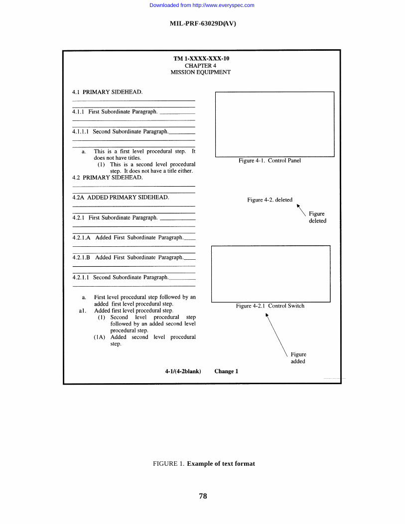
MIL-PRF-63029D(AV)
78
FIGURE 1. Example of text format
Downloaded from http://www.everyspec.com
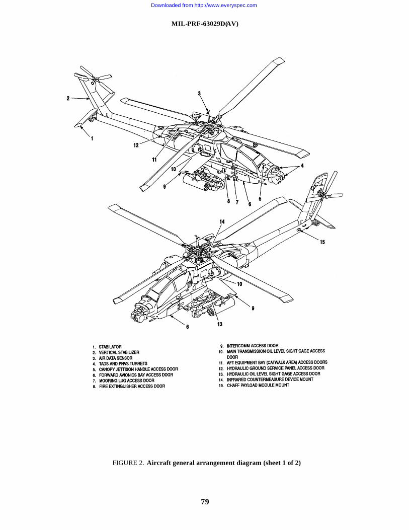
MIL-PRF-63029D(AV)
79
FIGURE 2. Aircraft general arrangement diagram (sheet 1 of 2)
Downloaded from http://www.everyspec.com
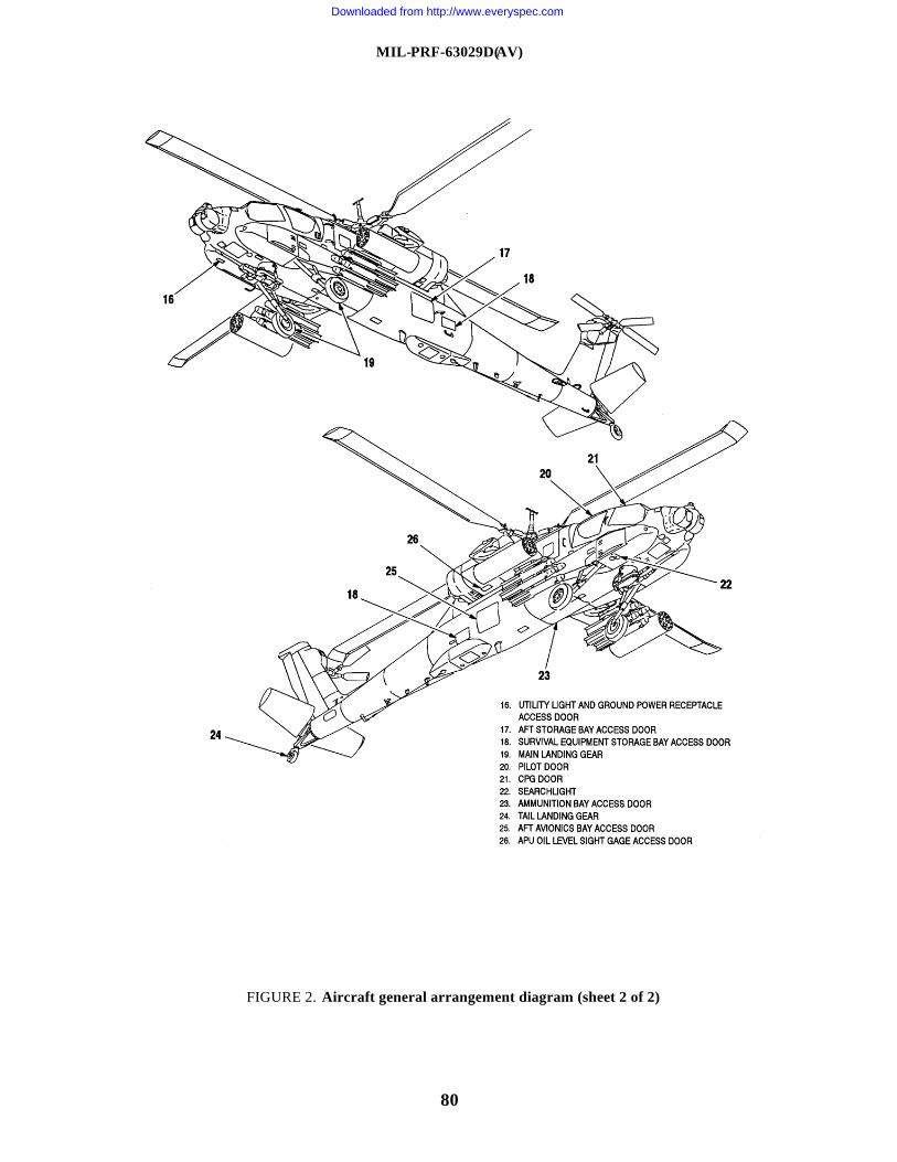
MIL-PRF-63029D(AV)
80
FIGURE 2. Aircraft general arrangement diagram (sheet 2 of 2)
Downloaded from http://www.everyspec.com
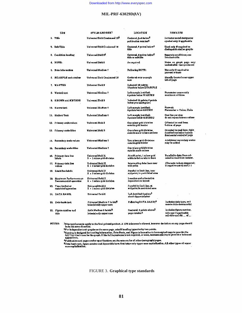
MIL-PRF-63029D(AV)
81
FIGURE 3. Graphical type standards
Downloaded from http://www.everyspec.com
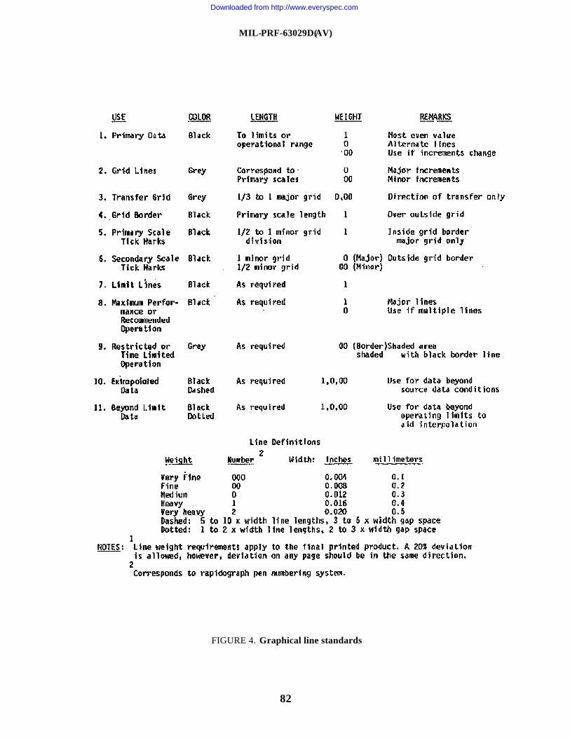
MIL-PRF-63029D(AV)
82
FIGURE 4. Graphical line standards
Downloaded from http://www.everyspec.com
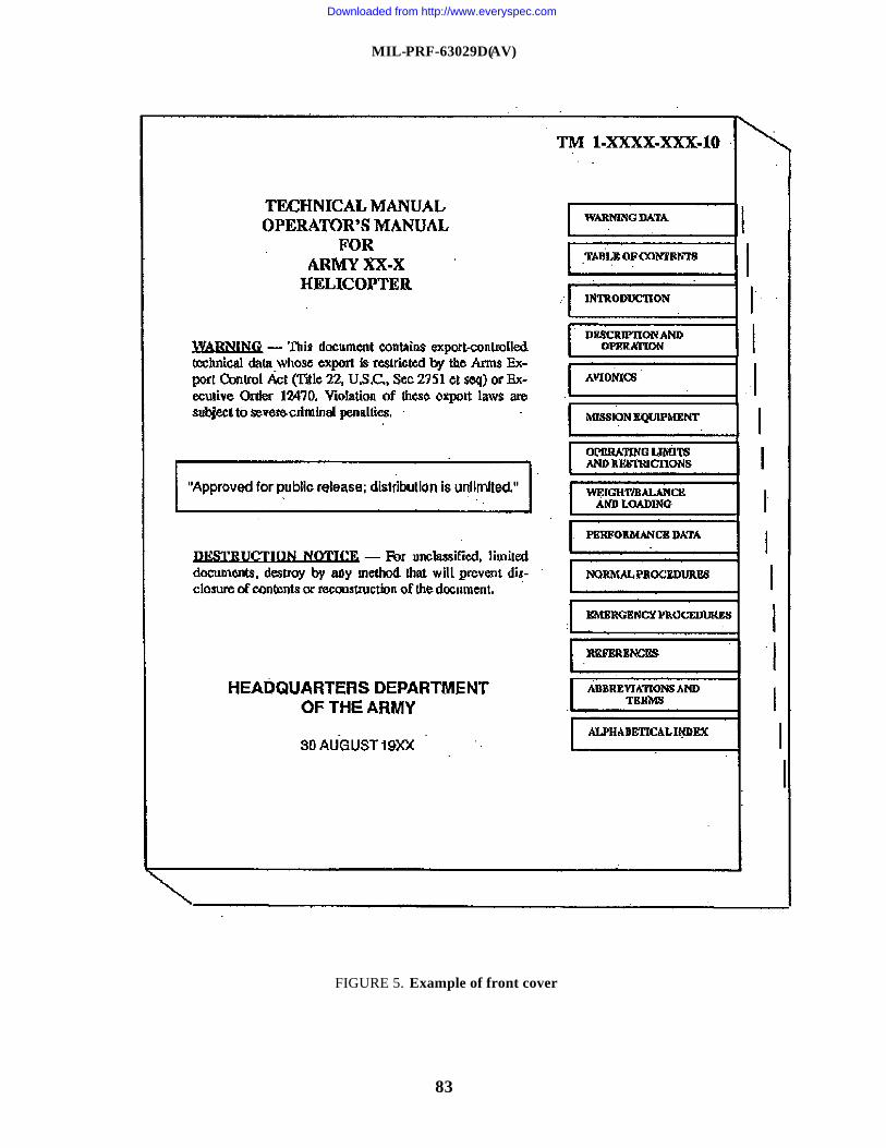
MIL-PRF-63029D(AV)
83
FIGURE 5. Example of front cover
Downloaded from http://www.everyspec.com
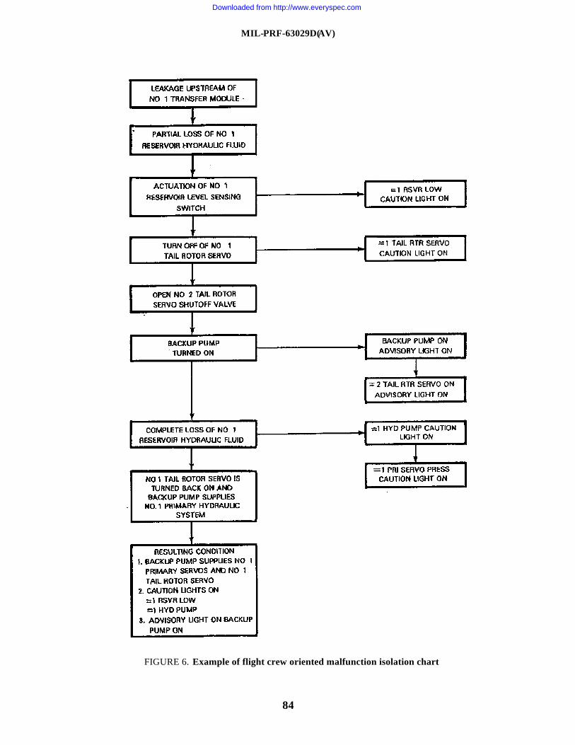
MIL-PRF-63029D(AV)
84
FIGURE 6. Example of flight crew oriented malfunction isolation chart
Downloaded from http://www.everyspec.com
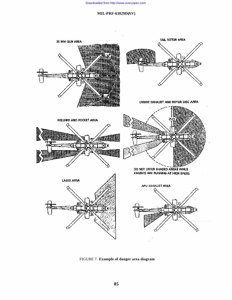
MIL-PRF-63029D(AV)
85
FIGURE 7. Example of danger area diagram
Downloaded from http://www.everyspec.com
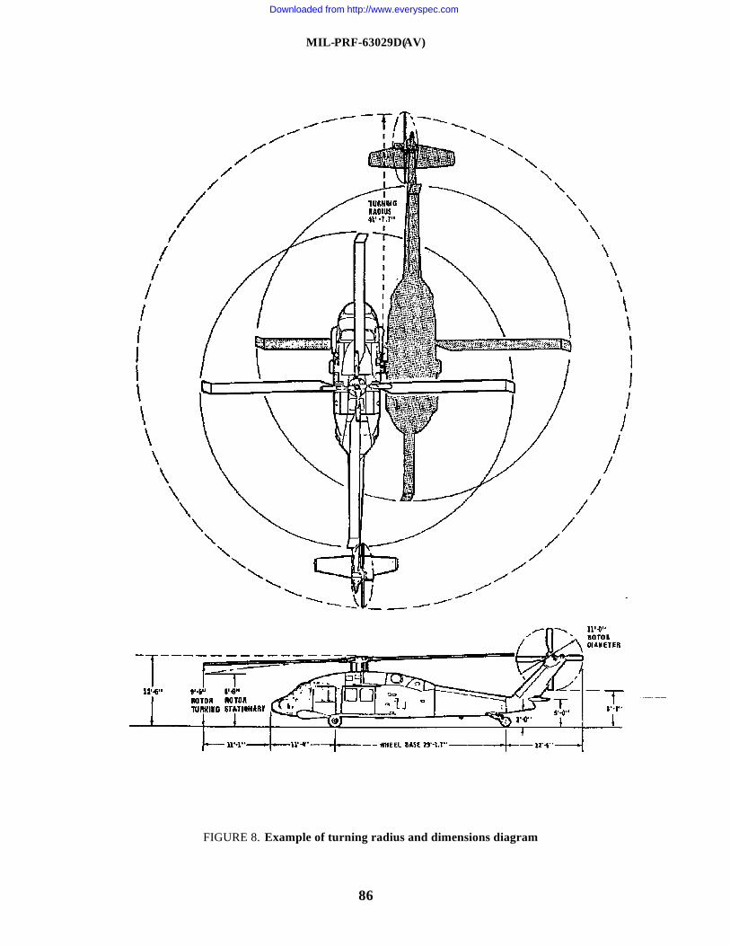
MIL-PRF-63029D(AV)
86
FIGURE 8. Example of turning radius and dimensions diagram
Downloaded from http://www.everyspec.com
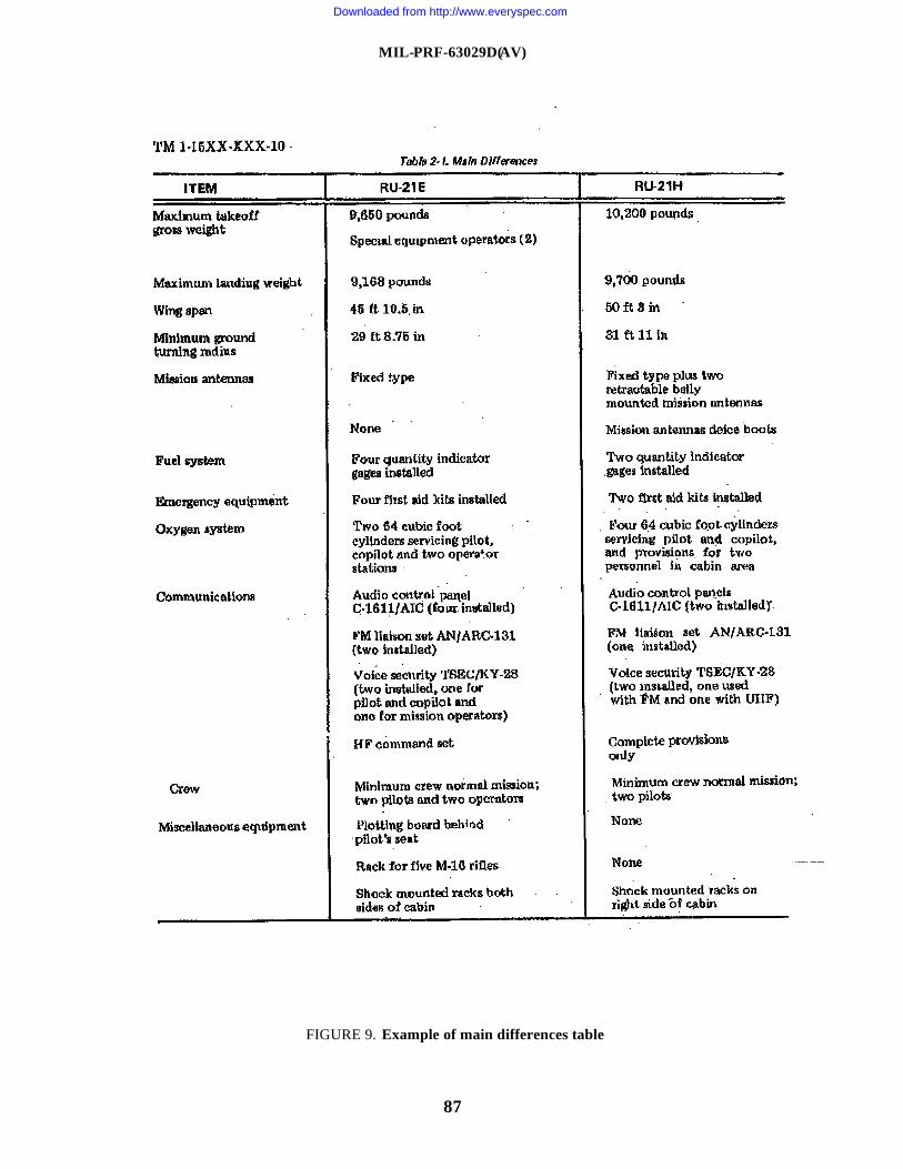
MIL-PRF-63029D(AV)
87
FIGURE 9. Example of main differences table
Downloaded from http://www.everyspec.com
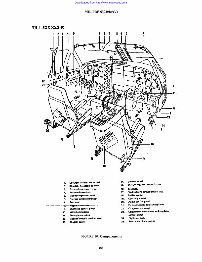
MIL-PRF-63029D(AV)
88
FIGURE 10. Compartments
Downloaded from http://www.everyspec.com
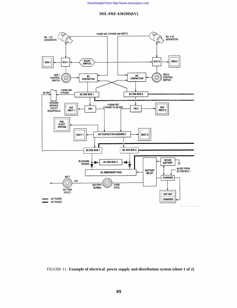
MIL-PRF-63029D(AV)
89
FIGURE 11. Example of electrical power supply and distribution system (sheet 1 of 2)
Downloaded from http://www.everyspec.com
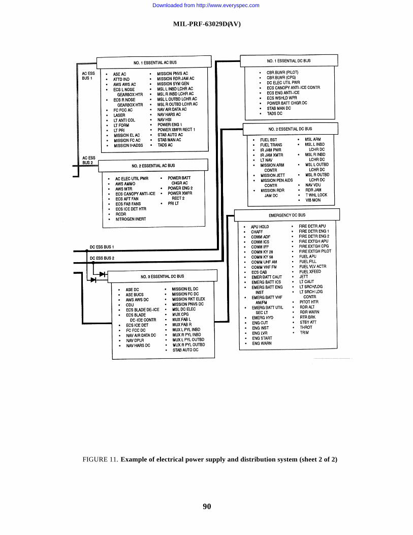
MIL-PRF-63029D(AV)
90
FIGURE 11. Example of electrical power supply and distribution system (sheet 2 of 2)
Downloaded from http://www.everyspec.com
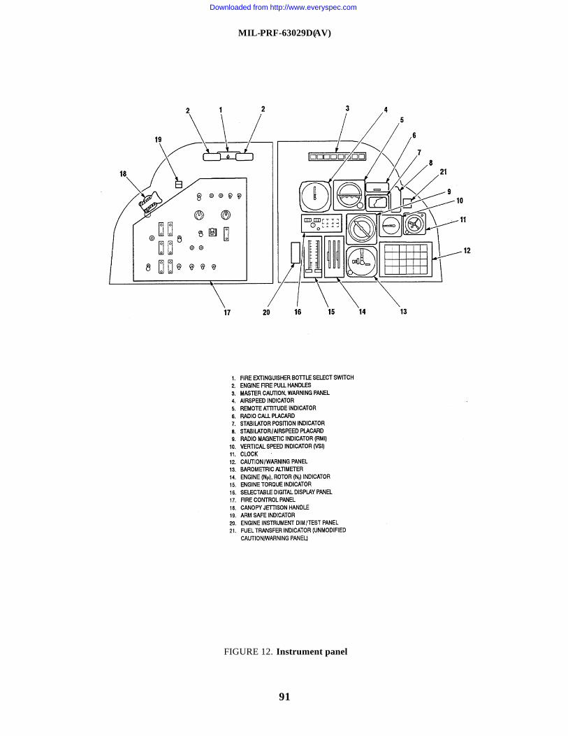
MIL-PRF-63029D(AV)
91
FIGURE 12. Instrument panel
Downloaded from http://www.everyspec.com
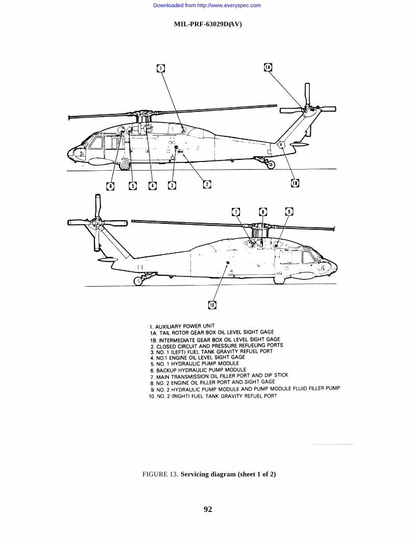
MIL-PRF-63029D(AV)
92
FIGURE 13. Servicing diagram (sheet 1 of 2)
Downloaded from http://www.everyspec.com
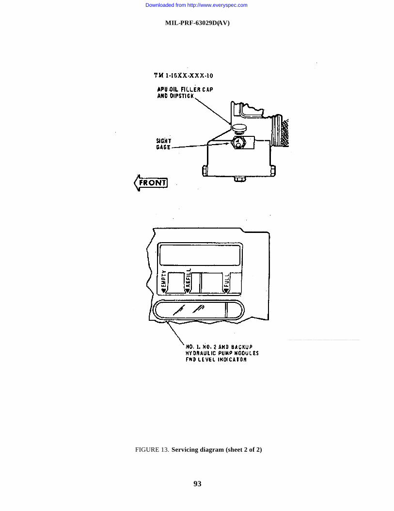
MIL-PRF-63029D(AV)
93
FIGURE 13. Servicing diagram (sheet 2 of 2)
Downloaded from http://www.everyspec.com
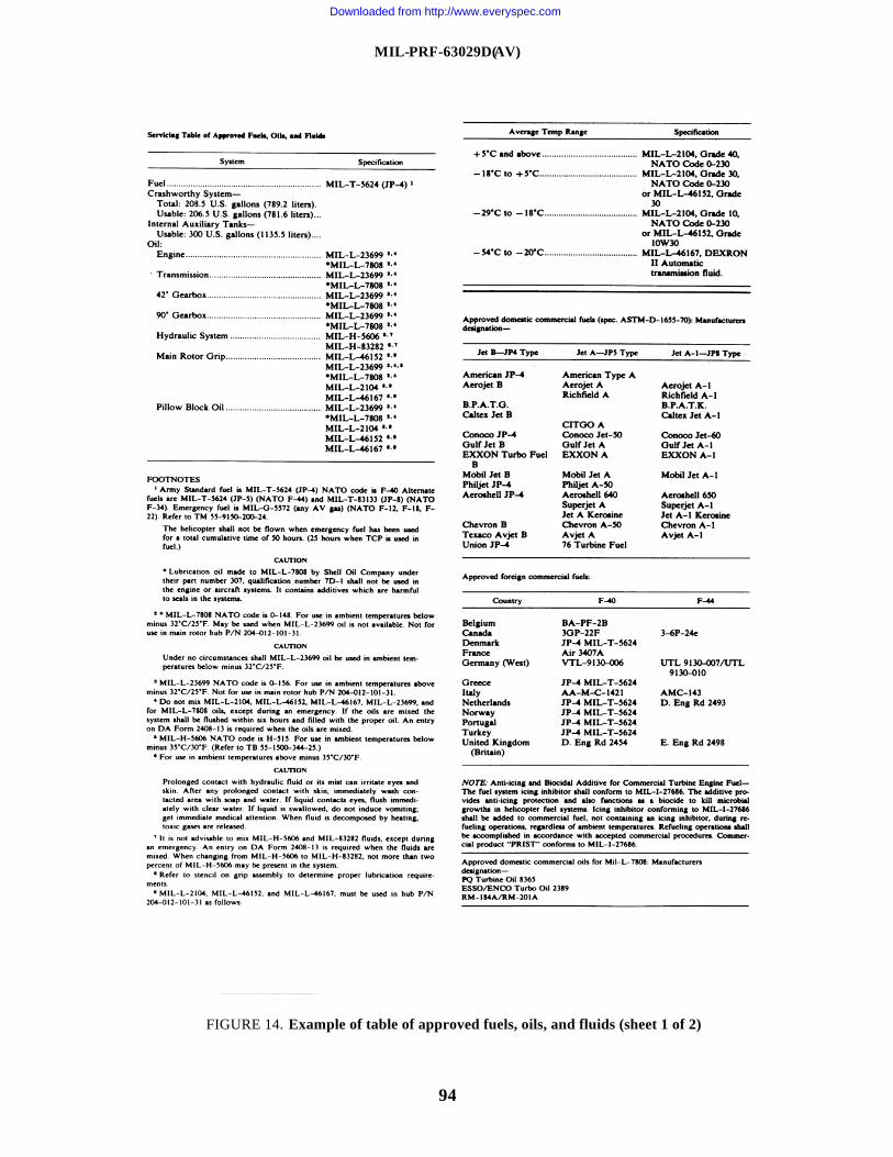
MIL-PRF-63029D(AV)
94
FIGURE 14. Example of table of approved fuels, oils, and fluids (sheet 1 of 2)
Downloaded from http://www.everyspec.com
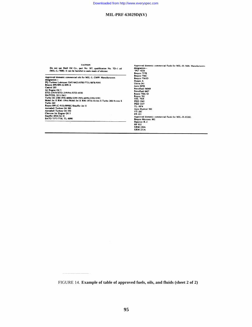
MIL-PRF-63029D(AV)
95
FIGURE 14. Example of table of approved fuels, oils, and fluids (sheet 2 of 2)
Downloaded from http://www.everyspec.com
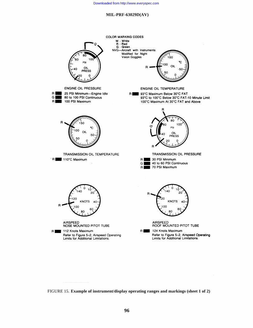
MIL-PRF-63029D(AV)
96
FIGURE 15. Example of instrument/display operating ranges and markings (sheet 1 of 2)
Downloaded from http://www.everyspec.com
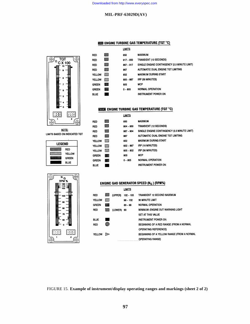
MIL-PRF-63029D(AV)
97
FIGURE 15. Example of instrument/display operating ranges and markings (sheet 2 of 2)
Downloaded from http://www.everyspec.com
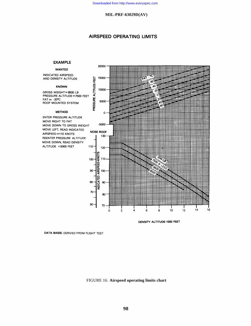
MIL-PRF-63029D(AV)
98
FIGURE 16. Airspeed operating limits chart
Downloaded from http://www.everyspec.com
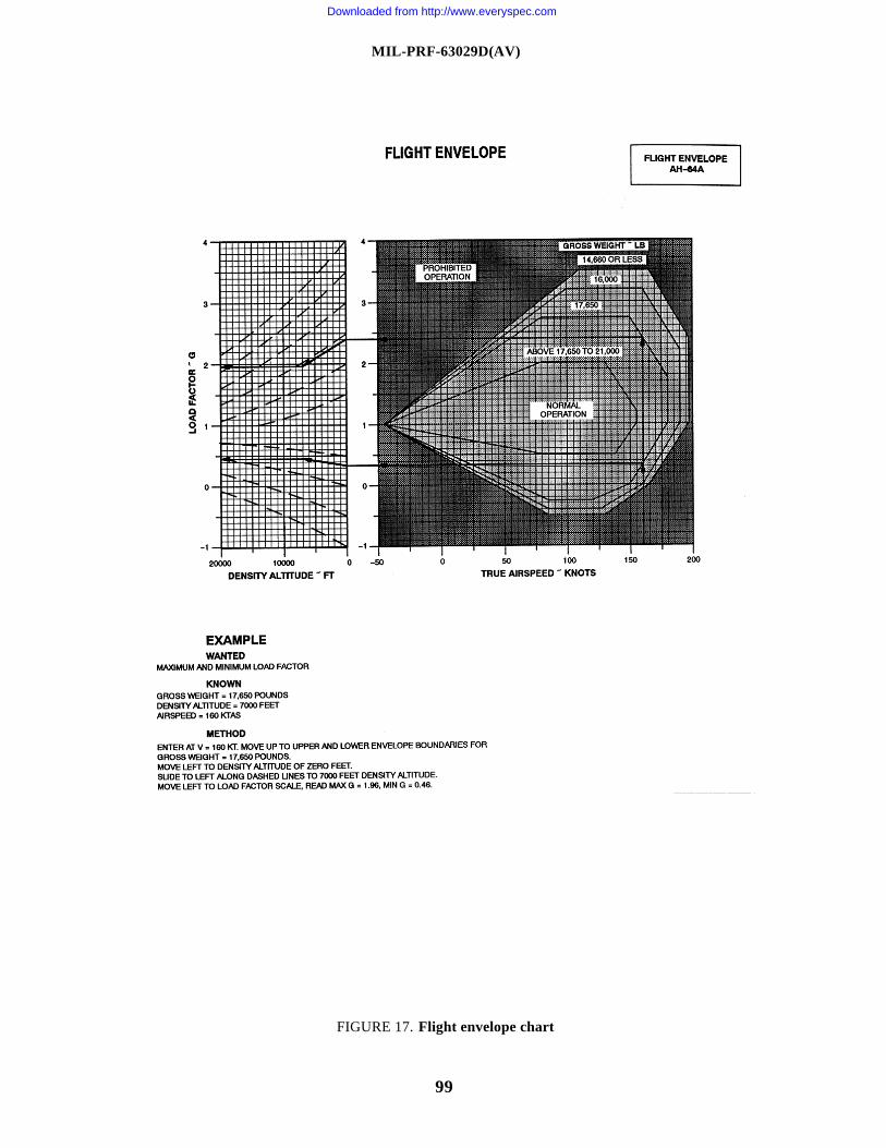
MIL-PRF-63029D(AV)
99
FIGURE 17. Flight envelope chart
Downloaded from http://www.everyspec.com
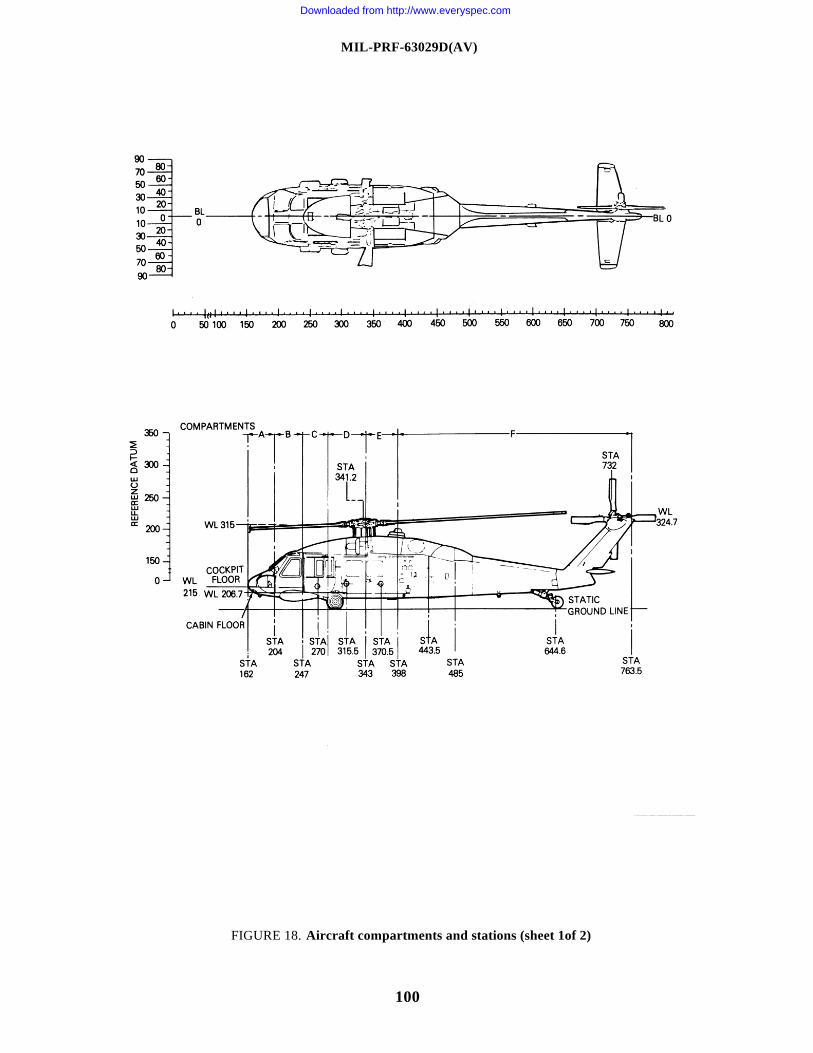
MIL-PRF-63029D(AV)
100
FIGURE 18. Aircraft compartments and stations (sheet 1of 2)
Downloaded from http://www.everyspec.com
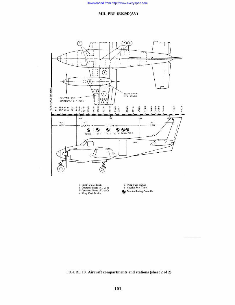
MIL-PRF-63029D(AV)
101
FIGURE 18. Aircraft compartments and stations (sheet 2 of 2)
Downloaded from http://www.everyspec.com
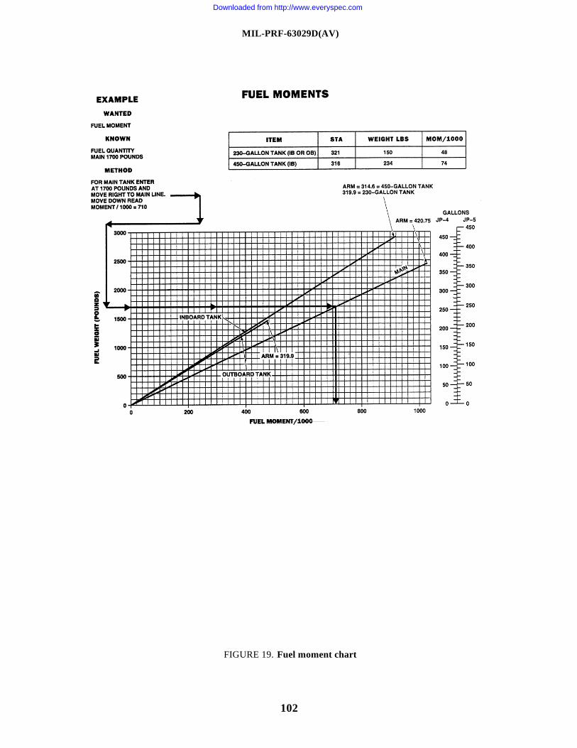
MIL-PRF-63029D(AV)
102
FIGURE 19. Fuel moment chart
Downloaded from http://www.everyspec.com
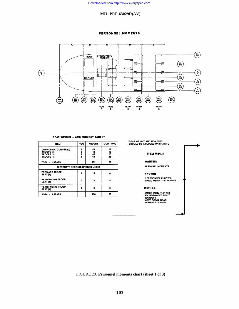
MIL-PRF-63029D(AV)
103
FIGURE 20. Personnel moments chart (sheet 1 of 3)
Downloaded from http://www.everyspec.com
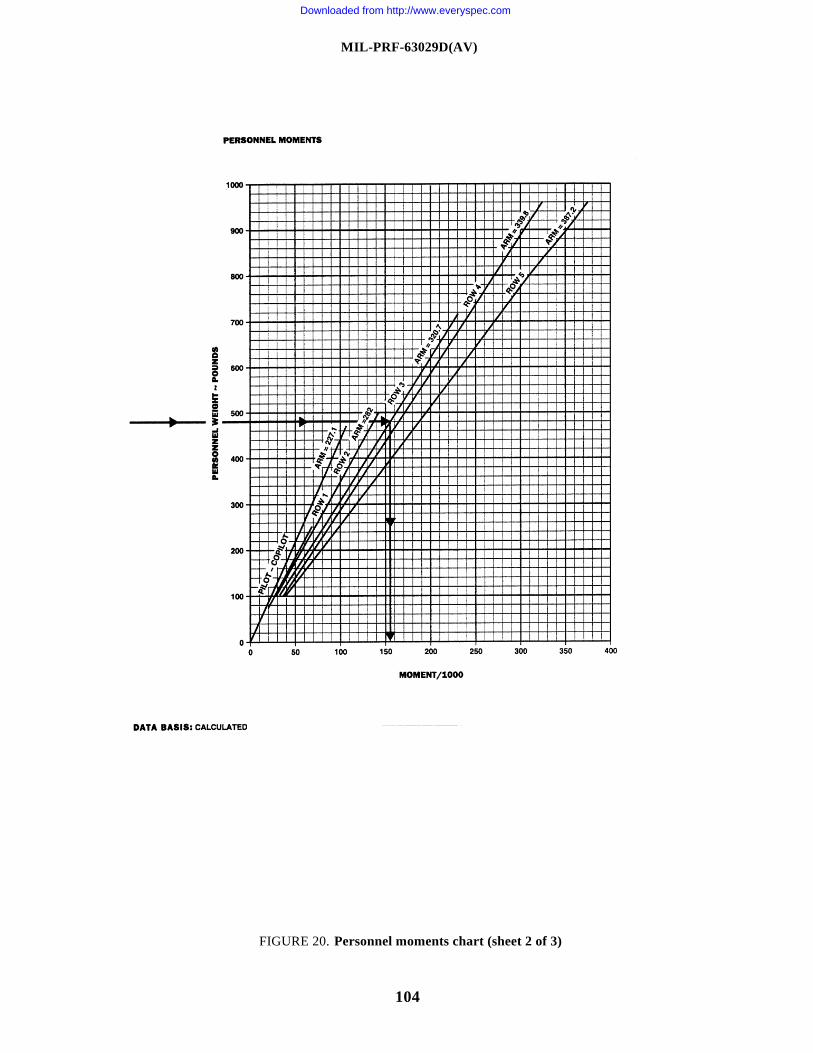
MIL-PRF-63029D(AV)
104
FIGURE 20. Personnel moments chart (sheet 2 of 3)
Downloaded from http://www.everyspec.com
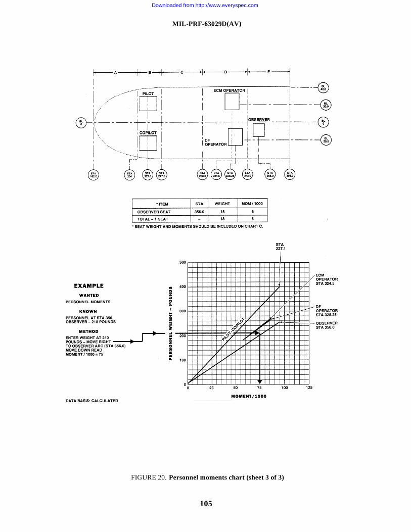
MIL-PRF-63029D(AV)
105
FIGURE 20. Personnel moments chart (sheet 3 of 3)
Downloaded from http://www.everyspec.com
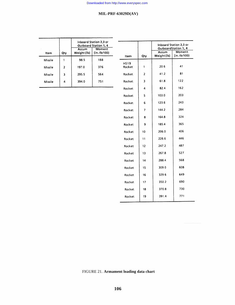
MIL-PRF-63029D(AV)
106
FIGURE 21. Armament loading data chart
Downloaded from http://www.everyspec.com
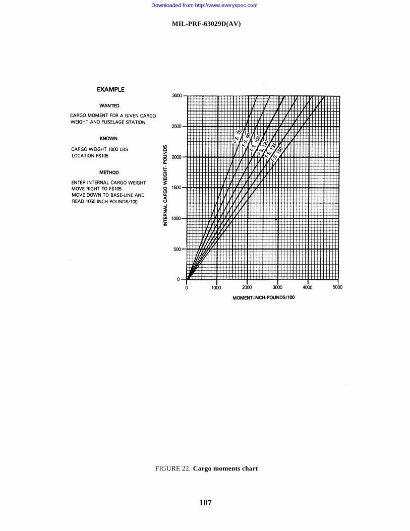
MIL-PRF-63029D(AV)
107
FIGURE 22. Cargo moments chart
Downloaded from http://www.everyspec.com
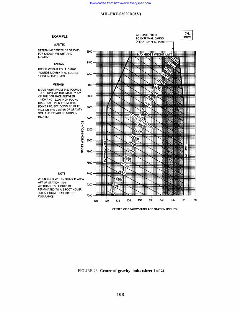
MIL-PRF-63029D(AV)
108
FIGURE 23. Center-of-gravity limits (sheet 1 of 2)
Downloaded from http://www.everyspec.com
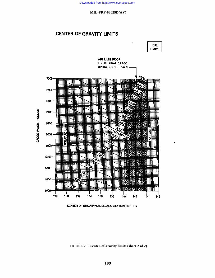
MIL-PRF-63029D(AV)
109
FIGURE 23. Center-of-gravity limits (sheet 2 of 2)
Downloaded from http://www.everyspec.com
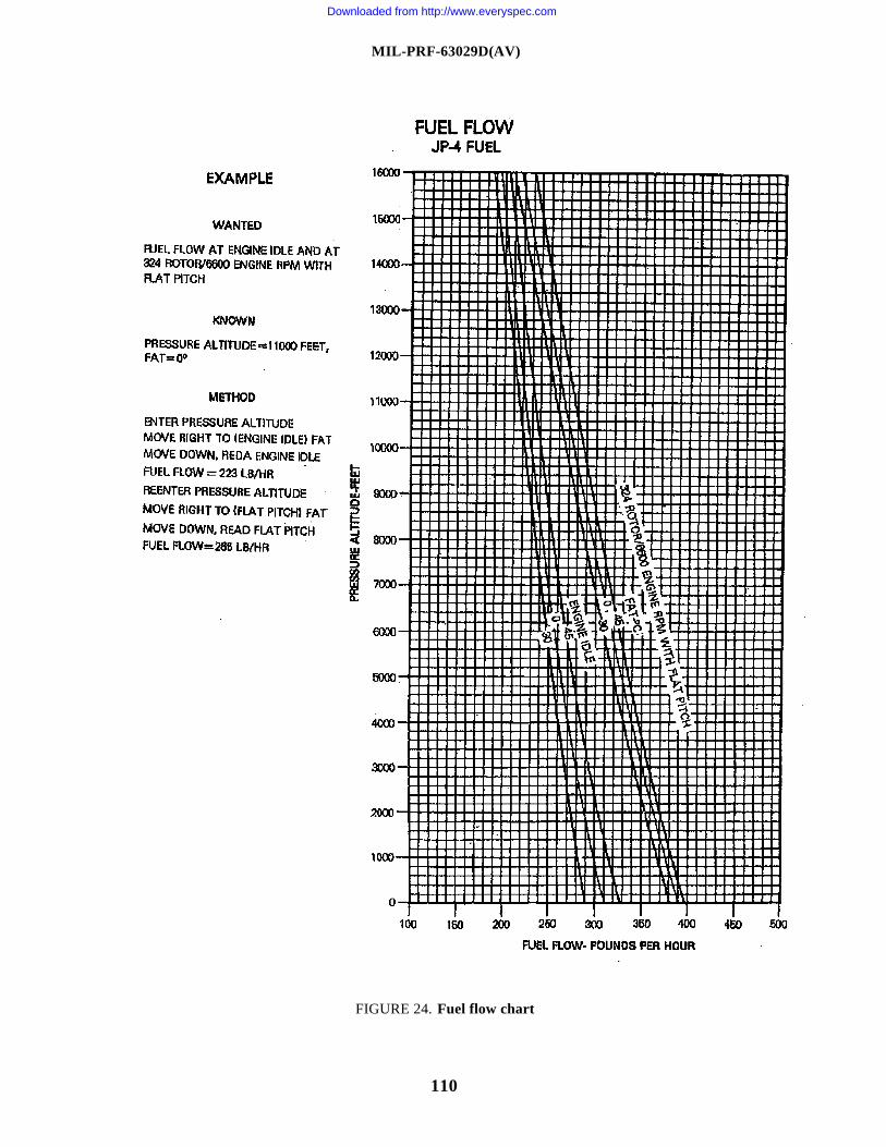
MIL-PRF-63029D(AV)
110
FIGURE 24. Fuel flow chart
Downloaded from http://www.everyspec.com
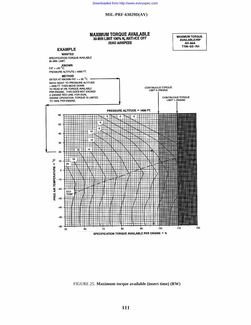
MIL-PRF-63029D(AV)
111
FIGURE 25. Maximum torque available (insert time) (RW)
Downloaded from http://www.everyspec.com
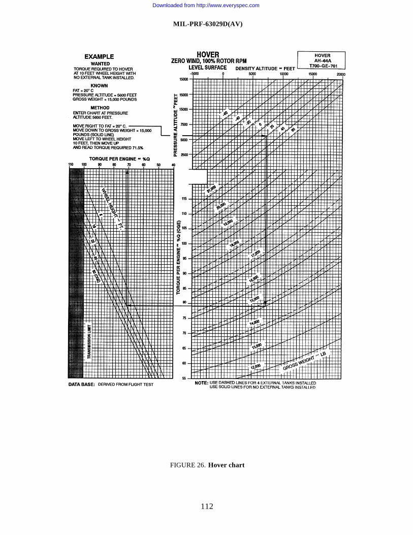
MIL-PRF-63029D(AV)
112
FIGURE 26. Hover chart
Downloaded from http://www.everyspec.com
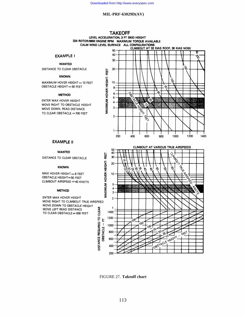
MIL-PRF-63029D(AV)
113
FIGURE 27. Takeoff chart
Downloaded from http://www.everyspec.com
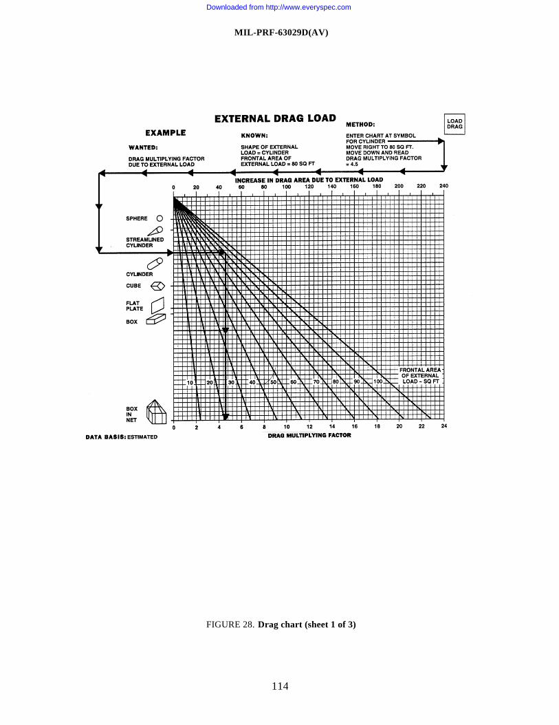
MIL-PRF-63029D(AV)
114
FIGURE 28. Drag chart (sheet 1 of 3)
Downloaded from http://www.everyspec.com
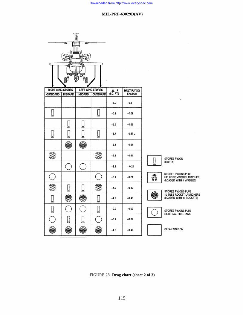
MIL-PRF-63029D(AV)
115
FIGURE 28. Drag chart (sheet 2 of 3)
Downloaded from http://www.everyspec.com
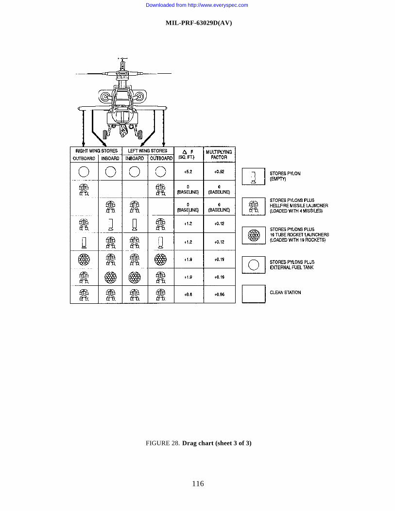
MIL-PRF-63029D(AV)
116
FIGURE 28. Drag chart (sheet 3 of 3)
Downloaded from http://www.everyspec.com
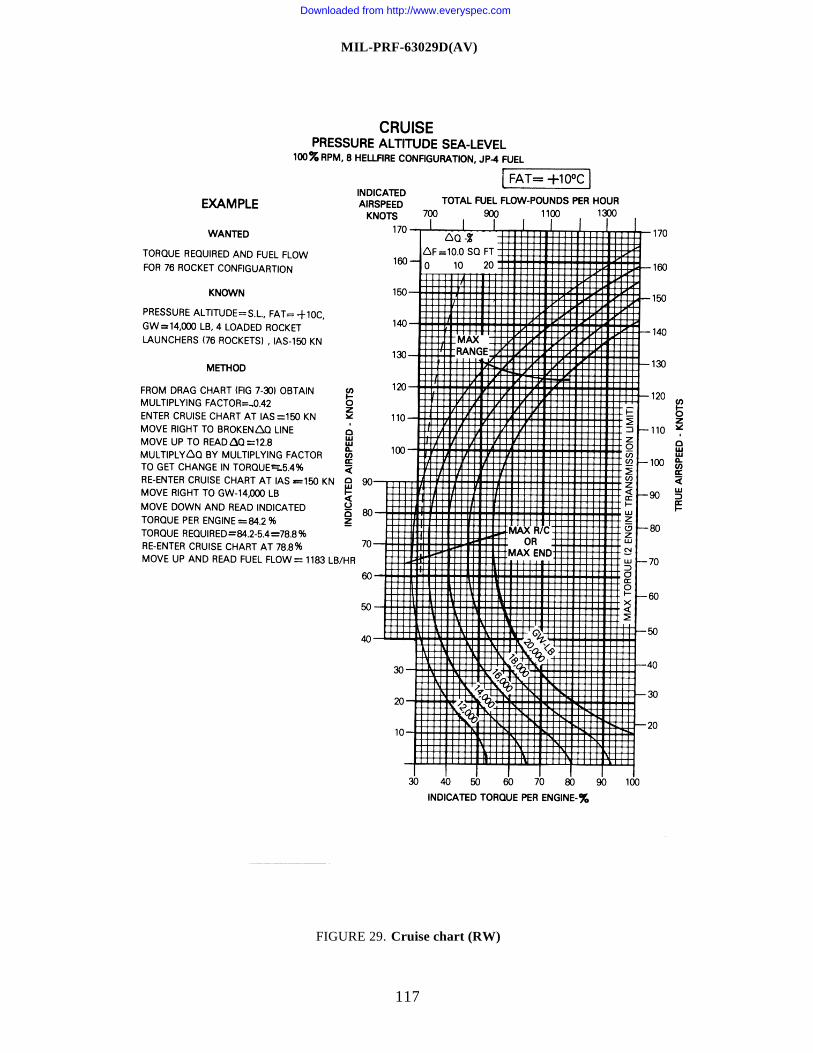
MIL-PRF-63029D(AV)
117
FIGURE 29. Cruise chart (RW)
Downloaded from http://www.everyspec.com
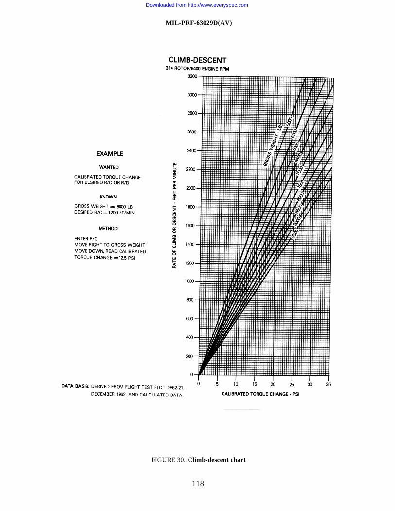
MIL-PRF-63029D(AV)
118
FIGURE 30. Climb-descent chart
Downloaded from http://www.everyspec.com
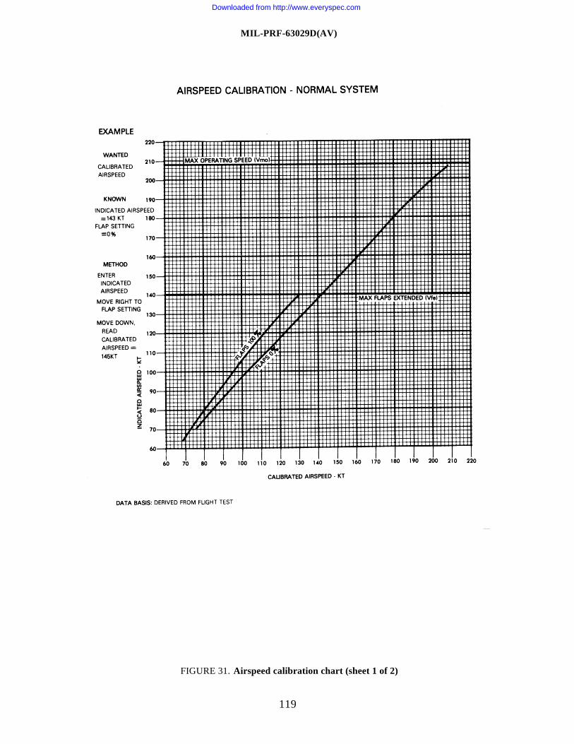
MIL-PRF-63029D(AV)
119
FIGURE 31. Airspeed calibration chart (sheet 1 of 2)
Downloaded from http://www.everyspec.com
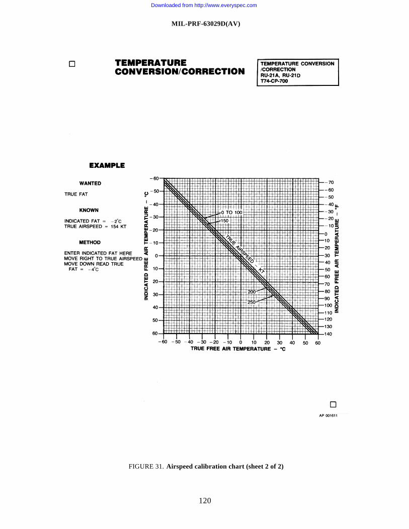
MIL-PRF-63029D(AV)
120
FIGURE 31. Airspeed calibration chart (sheet 2 of 2)
Downloaded from http://www.everyspec.com
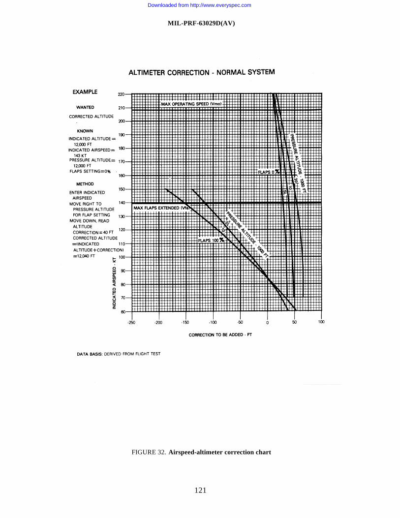
MIL-PRF-63029D(AV)
121
FIGURE 32. Airspeed-altimeter correction chart
Downloaded from http://www.everyspec.com
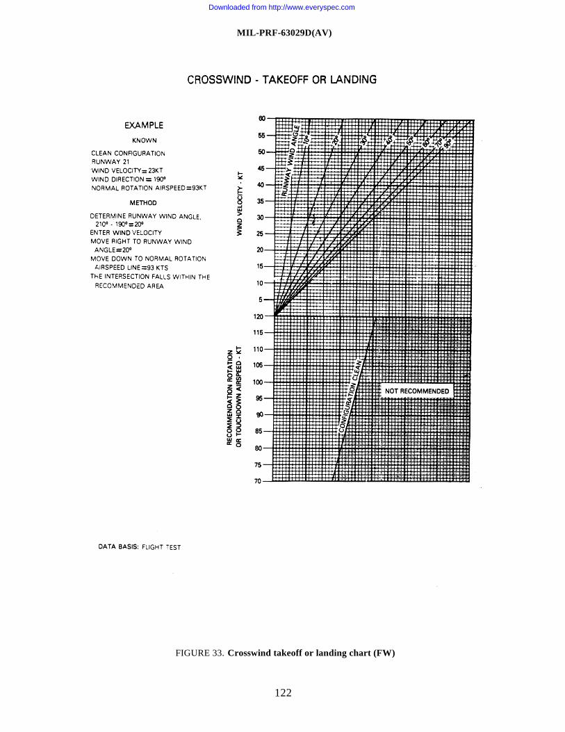
MIL-PRF-63029D(AV)
122
FIGURE 33. Crosswind takeoff or landing chart (FW)
Downloaded from http://www.everyspec.com
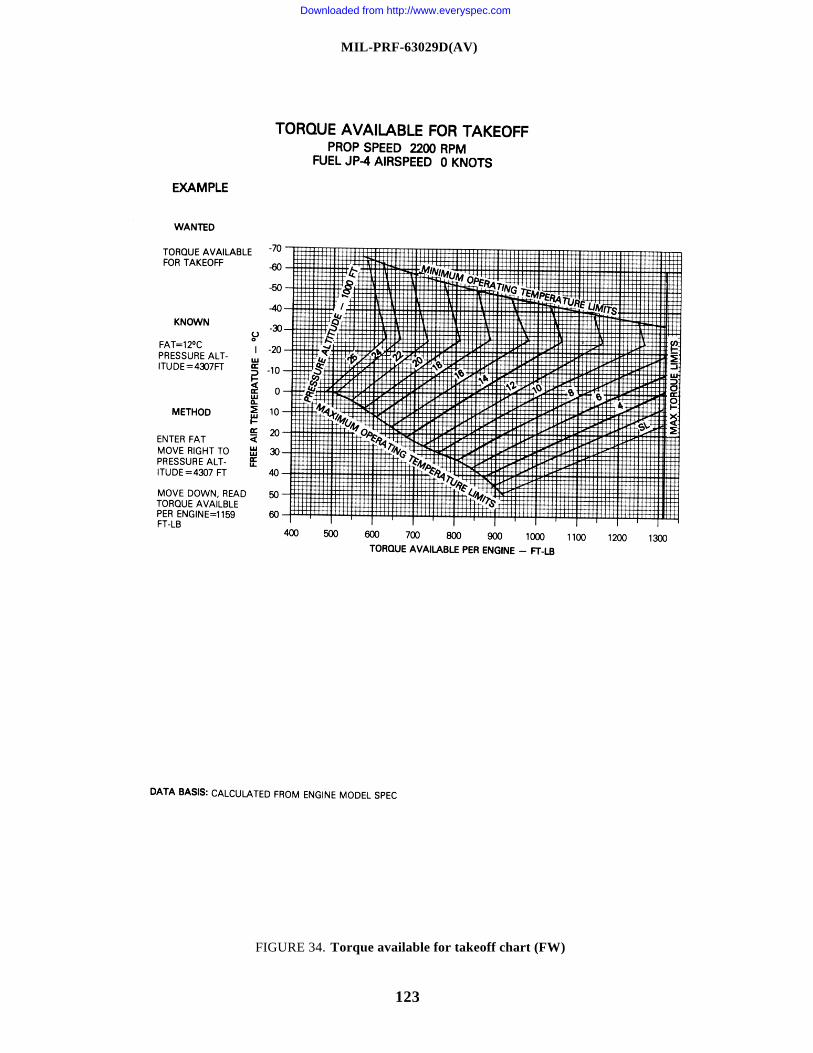
MIL-PRF-63029D(AV)
123
FIGURE 34. Torque available for takeoff chart (FW)
Downloaded from http://www.everyspec.com
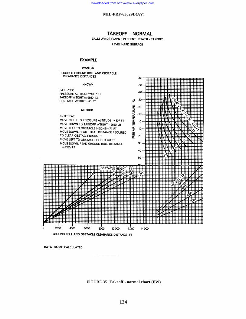
MIL-PRF-63029D(AV)
124
FIGURE 35. Takeoff - normal chart (FW)
Downloaded from http://www.everyspec.com
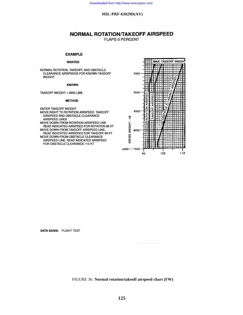
MIL-PRF-63029D(AV)
125
FIGURE 36. Normal rotation/takeoff airspeed chart (FW)
Downloaded from http://www.everyspec.com
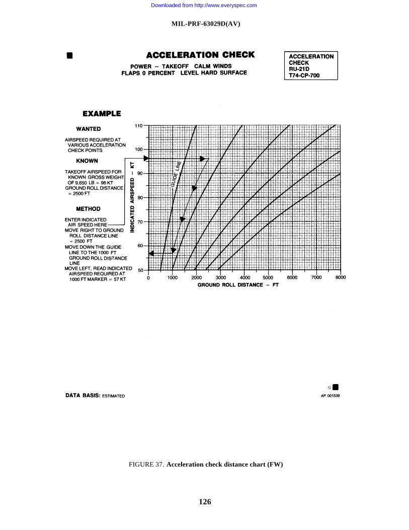
MIL-PRF-63029D(AV)
126
FIGURE 37. Acceleration check distance chart (FW)
Downloaded from http://www.everyspec.com
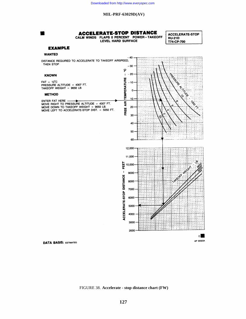
MIL-PRF-63029D(AV)
127
FIGURE 38. Accelerate - stop distance chart (FW)
Downloaded from http://www.everyspec.com
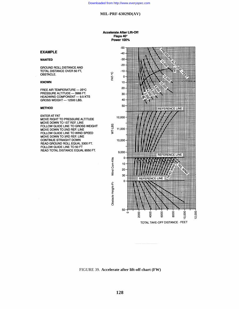
MIL-PRF-63029D(AV)
128
FIGURE 39. Accelerate after lift-off chart (FW)
Downloaded from http://www.everyspec.com
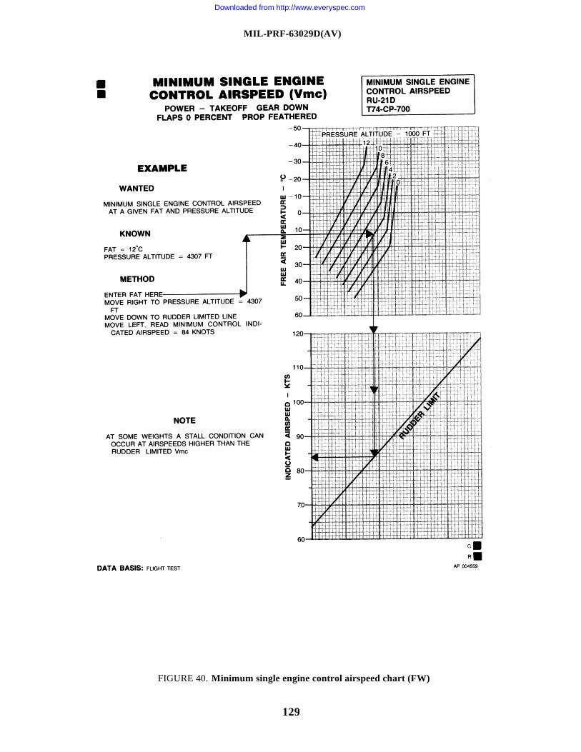
MIL-PRF-63029D(AV)
129
FIGURE 40. Minimum single engine control airspeed chart (FW)
Downloaded from http://www.everyspec.com
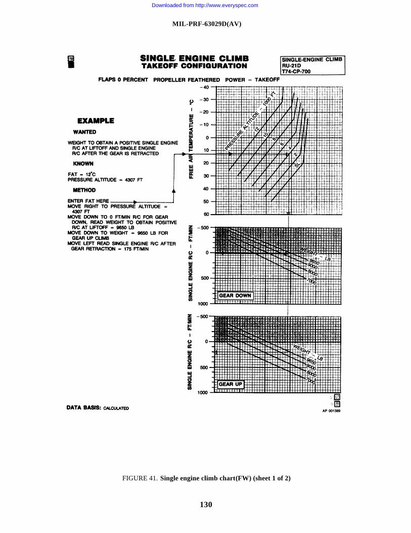
MIL-PRF-63029D(AV)
130
FIGURE 41. Single engine climb chart (FW) (sheet 1 of 2)
Downloaded from http://www.everyspec.com
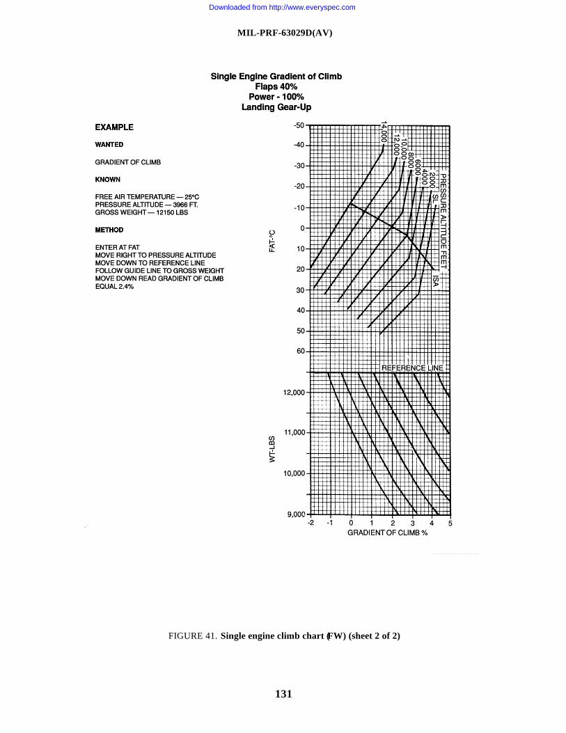
MIL-PRF-63029D(AV)
131
FIGURE 41. Single engine climb chart (FW) (sheet 2 of 2)
Downloaded from http://www.everyspec.com
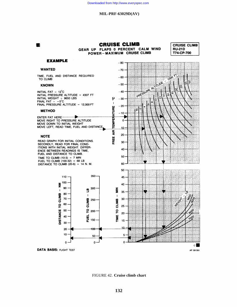
MIL-PRF-63029D(AV)
132
FIGURE 42. Cruise climb chart
Downloaded from http://www.everyspec.com
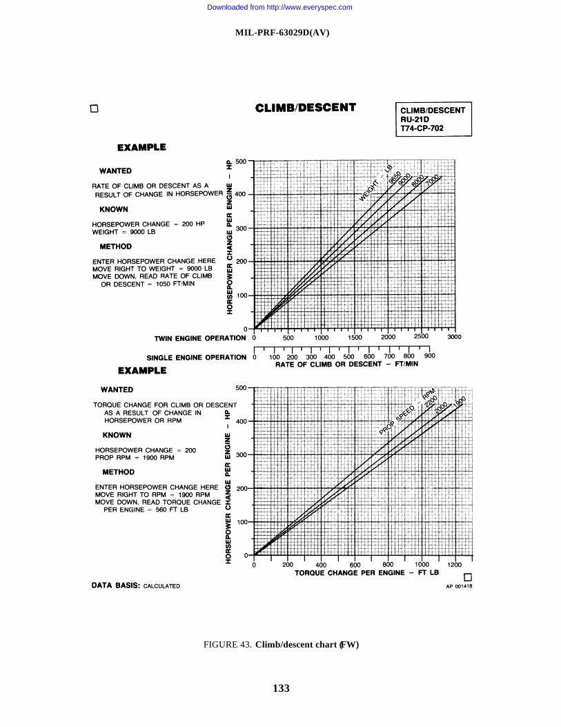
MIL-PRF-63029D(AV)
133
FIGURE 43. Climb/descent chart (FW)
Downloaded from http://www.everyspec.com
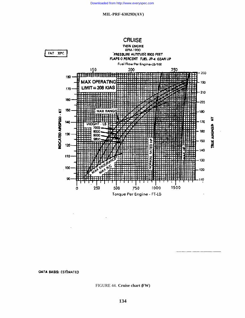
MIL-PRF-63029D(AV)
134
FIGURE 44. Cruise chart (FW)
Downloaded from http://www.everyspec.com
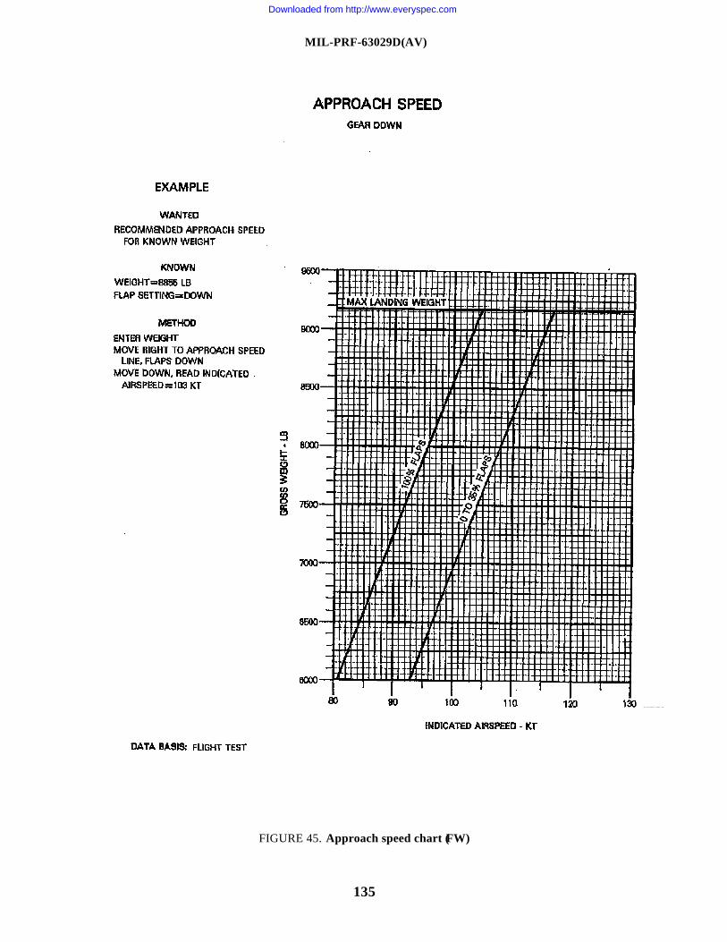
MIL-PRF-63029D(AV)
135
FIGURE 45. Approach speed chart (FW)
Downloaded from http://www.everyspec.com
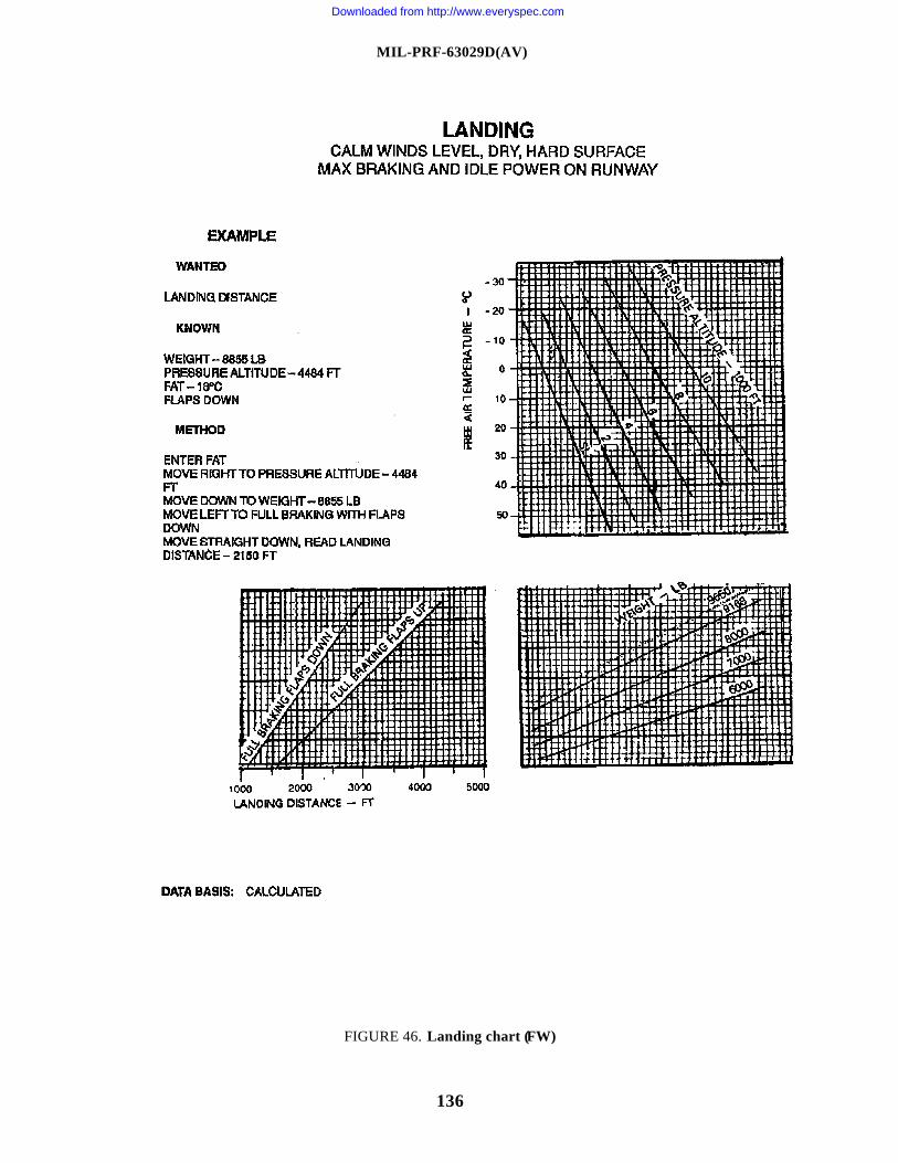
MIL-PRF-63029D(AV)
136
FIGURE 46. Landing chart (FW)
Downloaded from http://www.everyspec.com
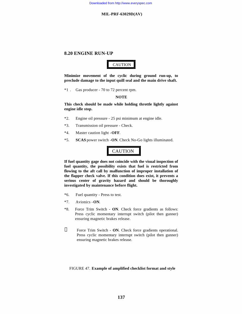
MIL-PRF-63029D(AV)
137
8.20 ENGINE RUN-UP
Minimize movement of the cyclic during ground run-up, topreclude damage to the input quill seal and the main drive shaft.
*1 . Gas producer - 70 to 72 percent rpm.
NOTE
This check should be made while holding throttle lightly againstengine idle stop.
*2. Engine oil pressure - 25 psi minimum at engine idle.
*3. Transmission oil pressure - Check.
*4. Master caution light - OFF.
*5. SCAS power switch - ON. Check No-Go lights illuminated.
If fuel quantity gage does not coincide with the visual inspection offuel quantity, the possibility exists that fuel is restricted fromflowing to the aft call by malfunction of improper installation ofthe flapper check valve. If this condition does exist, it prevents aserious center of gravity hazard and should be thoroughlyinvestigated by maintenance before flight.
*6. Fuel quantity - Press to test.
*7. Avionics - ON.
*8. Force Trim Switch - ON. Check force gradients as follows:Press cyclic momentary interrupt switch (pilot then gunner)ensuring magnetic brakes release.
⑨ Force Trim Switch - ON. Check force gradients operational.Press cyclic momentary interrupt switch (pilot then gunner)ensuring magnetic brakes release.
FIGURE 47. Example of amplified checklist format and style
CAUTION
CAUTION
Downloaded from http://www.everyspec.com
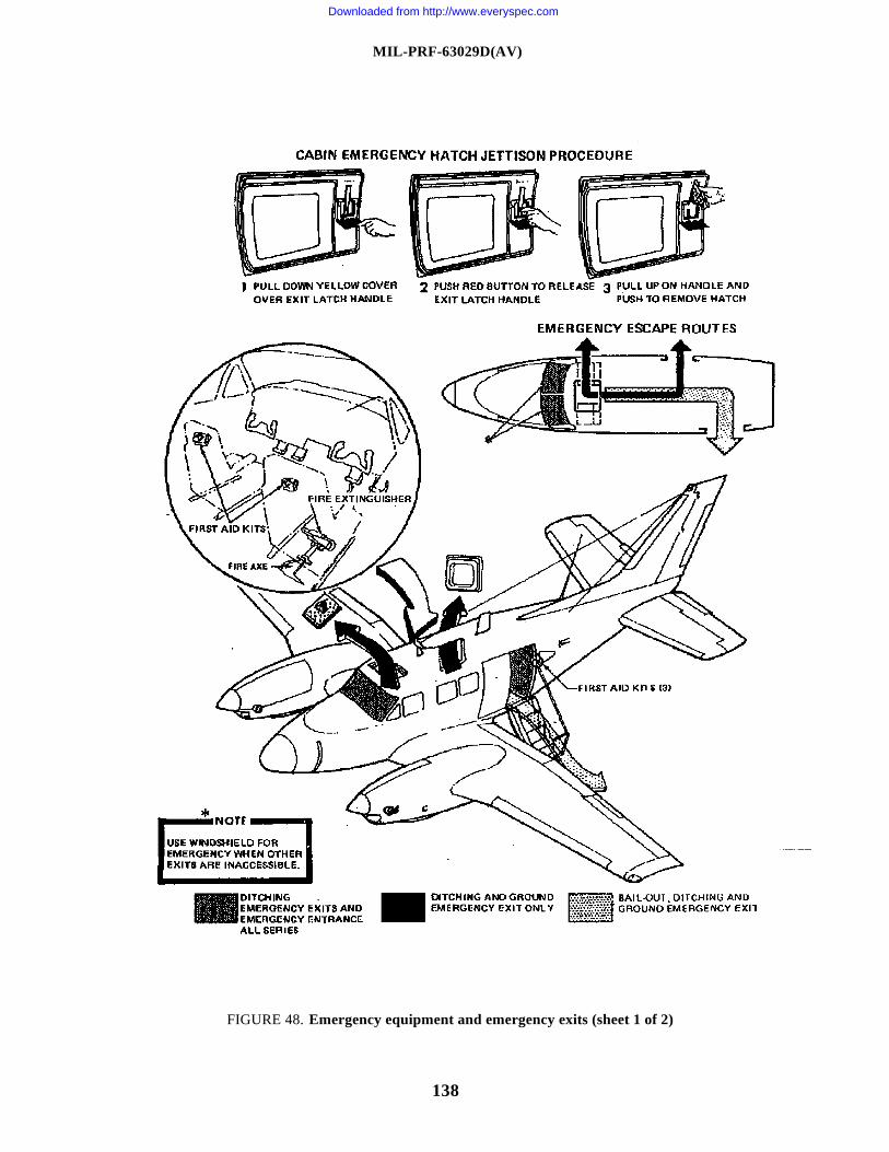
MIL-PRF-63029D(AV)
138
FIGURE 48. Emergency equipment and emergency exits (sheet 1 of 2)
Downloaded from http://www.everyspec.com
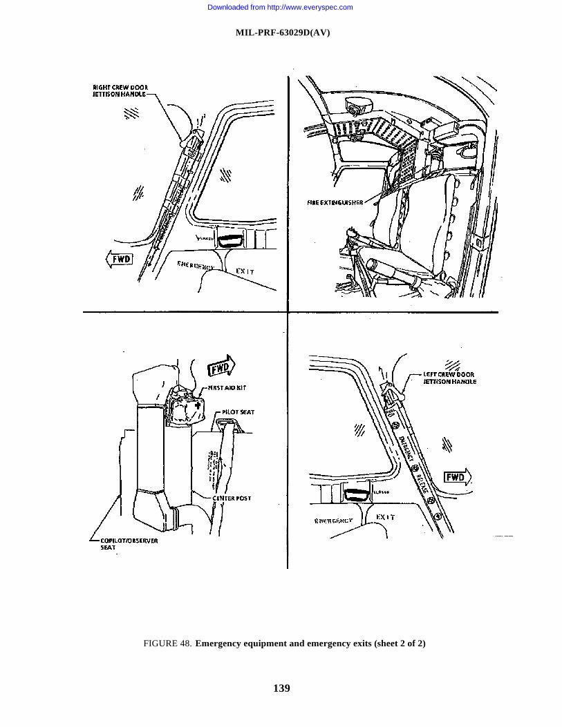
MIL-PRF-63029D(AV)
139
FIGURE 48. Emergency equipment and emergency exits (sheet 2 of 2)
Downloaded from http://www.everyspec.com
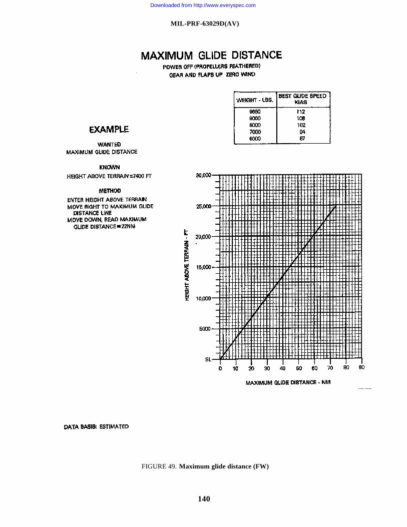
MIL-PRF-63029D(AV)
140
FIGURE 49. Maximum glide distance (FW)
Downloaded from http://www.everyspec.com
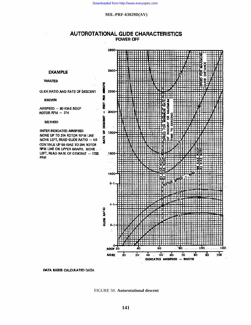
MIL-PRF-63029D(AV)
141
FIGURE 50. Autorotational descent
Downloaded from http://www.everyspec.com
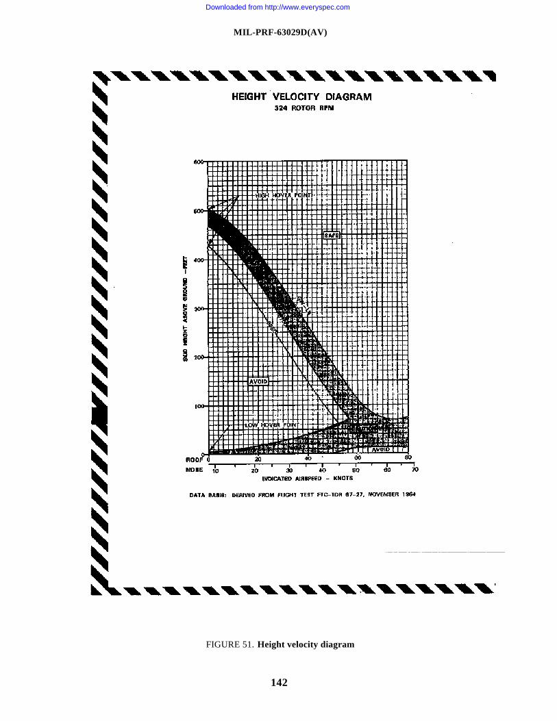
MIL-PRF-63029D(AV)
142
FIGURE 51. Height velocity diagram
Downloaded from http://www.everyspec.com
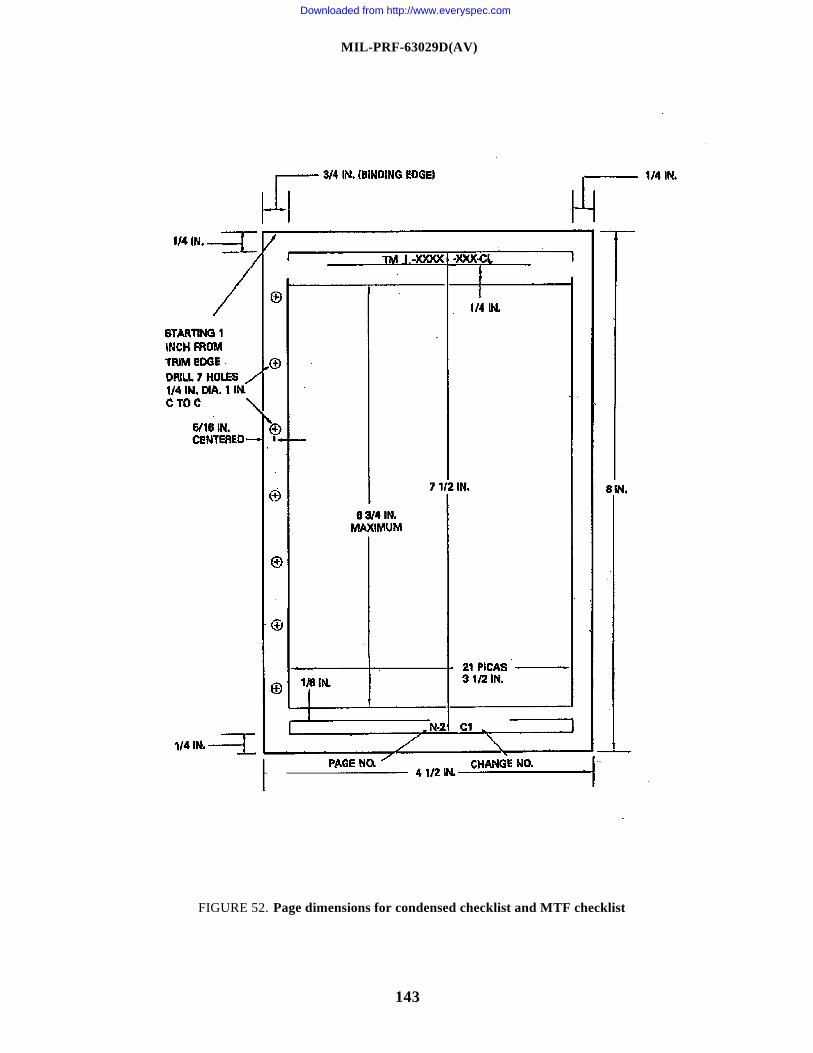
MIL-PRF-63029D(AV)
143
FIGURE 52. Page dimensions for condensed checklist and MTF checklist
Downloaded from http://www.everyspec.com
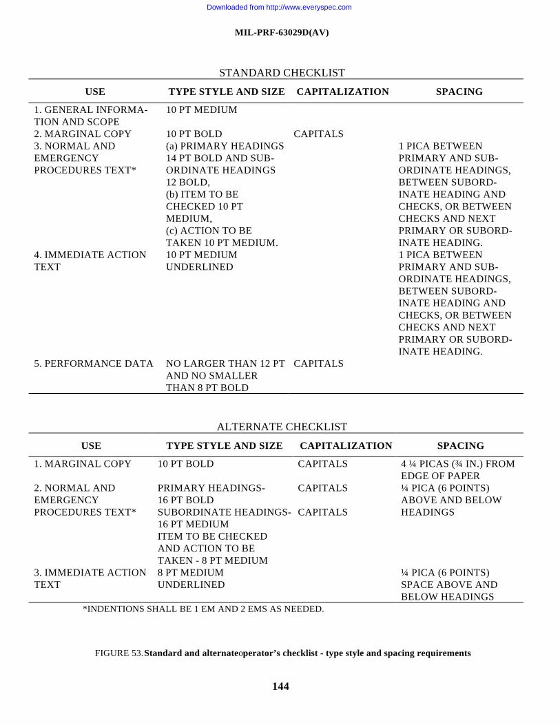
MIL-PRF-63029D(AV)
144
STANDARD CHECKLIST
USE TYPE STYLE AND SIZE CAPITALIZATION SPACING
1. GENERAL INFORMA-TION AND SCOPE
10 PT MEDIUM
2. MARGINAL COPY 10 PT BOLD CAPITALS3. NORMAL ANDEMERGENCYPROCEDURES TEXT*
(a) PRIMARY HEADINGS14 PT BOLD AND SUB-ORDINATE HEADINGS12 BOLD,(b) ITEM TO BECHECKED 10 PTMEDIUM,(c) ACTION TO BETAKEN 10 PT MEDIUM.
1 PICA BETWEENPRIMARY AND SUB-ORDINATE HEADINGS,BETWEEN SUBORD-INATE HEADING ANDCHECKS, OR BETWEENCHECKS AND NEXTPRIMARY OR SUBORD-INATE HEADING.
4. IMMEDIATE ACTIONTEXT
10 PT MEDIUMUNDERLINED
1 PICA BETWEENPRIMARY AND SUB-ORDINATE HEADINGS,BETWEEN SUBORD-INATE HEADING ANDCHECKS, OR BETWEENCHECKS AND NEXTPRIMARY OR SUBORD-INATE HEADING.
5. PERFORMANCE DATA NO LARGER THAN 12 PTAND NO SMALLERTHAN 8 PT BOLD
CAPITALS
ALTERNATE CHECKLIST
USE TYPE STYLE AND SIZE CAPITALIZATION SPACING
1. MARGINAL COPY 10 PT BOLD CAPITALS 4 ¼ PICAS (¾ IN.) FROMEDGE OF PAPER
2. NORMAL ANDEMERGENCYPROCEDURES TEXT*
PRIMARY HEADINGS-16 PT BOLDSUBORDINATE HEADINGS-16 PT MEDIUMITEM TO BE CHECKEDAND ACTION TO BETAKEN - 8 PT MEDIUM
CAPITALS
CAPITALS
¼ PICA (6 POINTS)ABOVE AND BELOWHEADINGS
3. IMMEDIATE ACTIONTEXT
8 PT MEDIUMUNDERLINED
¼ PICA (6 POINTS)SPACE ABOVE ANDBELOW HEADINGS
*INDENTIONS SHALL BE 1 EM AND 2 EMS AS NEEDED.
FIGURE 53. Standard and alternate operator’s checklist - type style and spacing requirements
Downloaded from http://www.everyspec.com
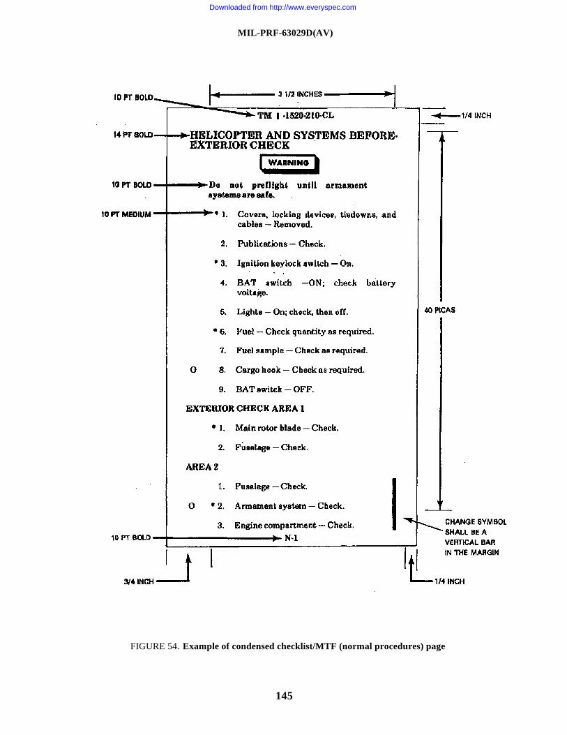
MIL-PRF-63029D(AV)
145
FIGURE 54. Example of condensed checklist/MTF (normal procedures) page
Downloaded from http://www.everyspec.com
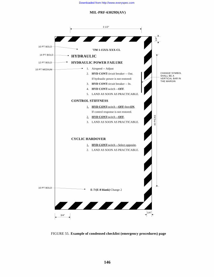
MIL-PRF-63029D(AV)
146
1. HYD CONT switch -- OFF then ON.
If control response is not restored.
2. HYD CONT switch -- OFF.
3. LAND AS SOON AS PRACTICABLE.
3 1/2"
'TM 1-15XX-XXX-CL
HYDRAULIC
HYDRAULIC POWER FAILURE
1. Airspeed -- Adjust
2. HYD CONT circuit breaker -- Out.
If hydraulic power is not restored:
3. HYD CONT circuit breaker -- In.
4. HYD CONT switch -- OFF.
5. LAND AS SOON AS PRACTICABLE.
CONTROL STIFFNESS
CYCLIC HARDOVER
1. HYD CONT switch -- Select opposite.
2. LAND AS SOON AS PRACTICABLE.
E-7/(E-8 blank) Change 2
3/4"1/4"
1/4"
40 P
ICA
S
CHANGE SYMBOLSHALL BE AVERTICAL BAR INTHE MARGIN
10 PT MEDIUM
12 PT BOLD
10 PT BOLD
14 PT BOLD
10 PT BOLD
FIGURE 55. Example of condensed checklist (emergency procedures) page
Downloaded from http://www.everyspec.com
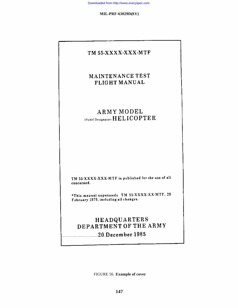
MIL-PRF-63029D(AV)
147
FIGURE 56. Example of cover
Downloaded from http://www.everyspec.com
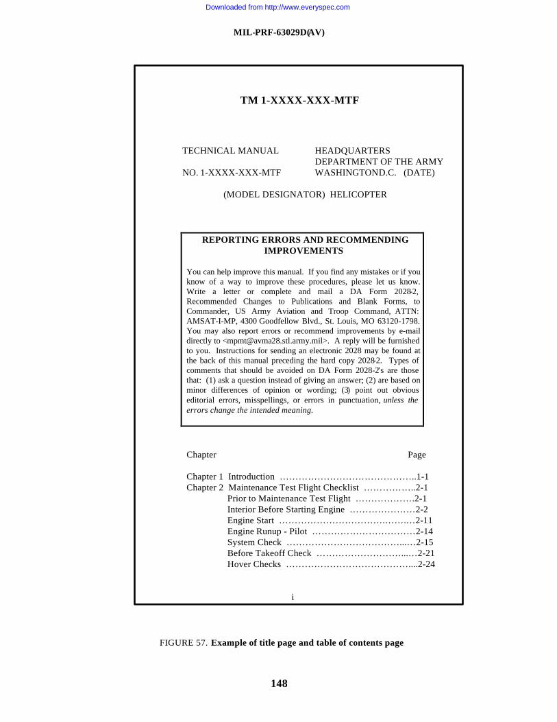
MIL-PRF-63029D(AV)
148
FIGURE 57. Example of title page and table of contents page
TM 1-XXXX-XXX-MTF
TECHNICAL MANUAL HEADQUARTERSDEPARTMENT OF THE ARMY
NO. 1-XXXX-XXX-MTF WASHINGTON D.C. (DATE)
(MODEL DESIGNATOR) HELICOPTER
REPORTING ERRORS AND RECOMMENDINGIMPROVEMENTS
You can help improve this manual. If you find any mistakes or if youknow of a way to improve these procedures, please let us know.Write a letter or complete and mail a DA Form 2028-2,Recommended Changes to Publications and Blank Forms, toCommander, US Army Aviation and Troop Command, ATTN:AMSAT-I-MP, 4300 Goodfellow Blvd., St. Louis, MO 63120-1798.You may also report errors or recommend improvements by e-maildirectly to <[email protected]>. A reply will be furnishedto you. Instructions for sending an electronic 2028 may be found atthe back of this manual preceding the hard copy 2028-2. Types ofcomments that should be avoided on DA Form 2028-2’s are thosethat: (1) ask a question instead of giving an answer; (2) are based onminor differences of opinion or wording; (3) point out obviouseditorial errors, misspellings, or errors in punctuation, unless theerrors change the intended meaning.
Chapter Page
Chapter 1 Introduction ……………………………………..1-1Chapter 2 Maintenance Test Flight Checklist ……………..2-1 Prior to Maintenance Test Flight ……………….2-1 Interior Before Starting Engine …………………2-2 Engine Start …………………………….…….…2-11 Engine Runup - Pilot ……………………………2-14 System Check ………………………………...…2-15 Before Takeoff Check ………………………...…2-21 Hover Checks …………………………………....2-24
i
Downloaded from http://www.everyspec.com
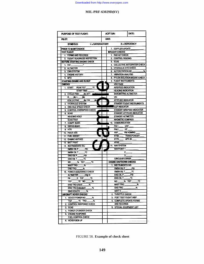
MIL-PRF-63029D(AV)
149
FIGURE 58. Example of check sheet
Downloaded from http://www.everyspec.com
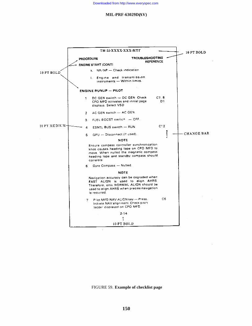
MIL-PRF-63029D(AV)
150
FIGURE 59. Example of checklist page
Downloaded from http://www.everyspec.com
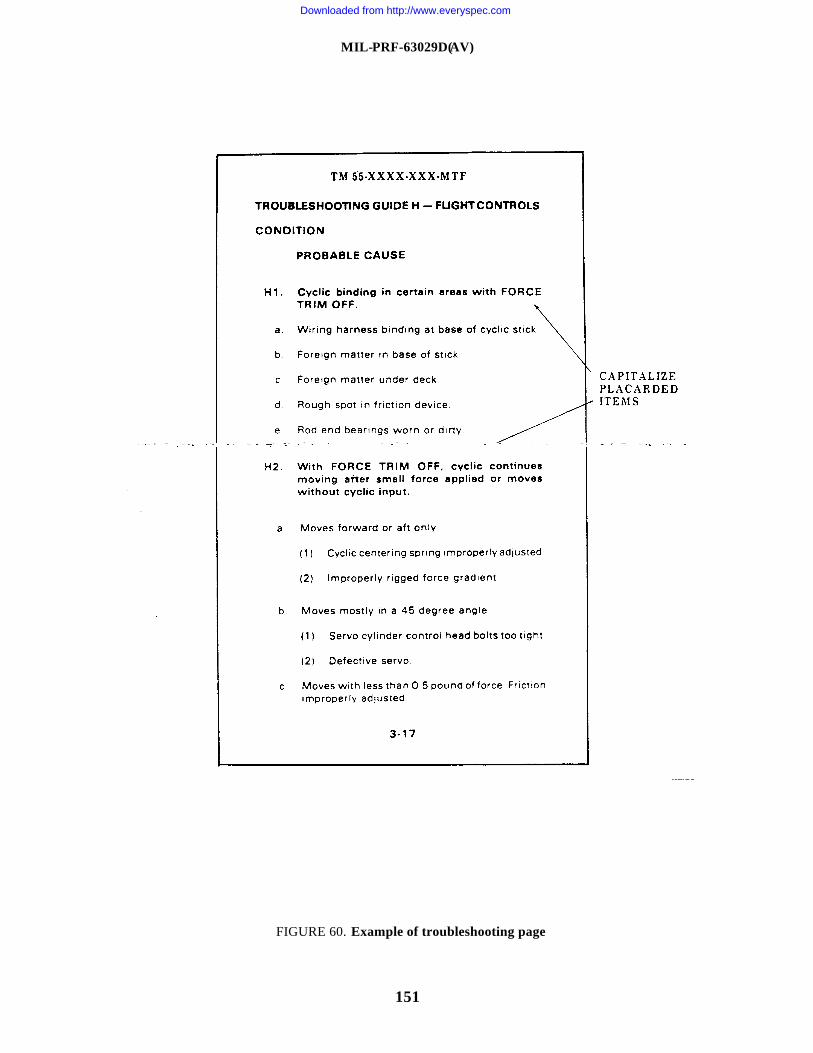
MIL-PRF-63029D(AV)
151
FIGURE 60. Example of troubleshooting page
Downloaded from http://www.everyspec.com
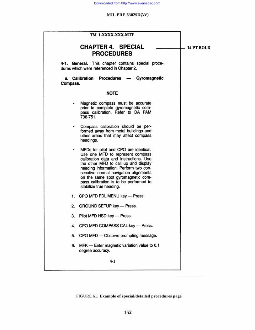
MIL-PRF-63029D(AV)
152
FIGURE 61. Example of special/detailed procedures page
Downloaded from http://www.everyspec.com
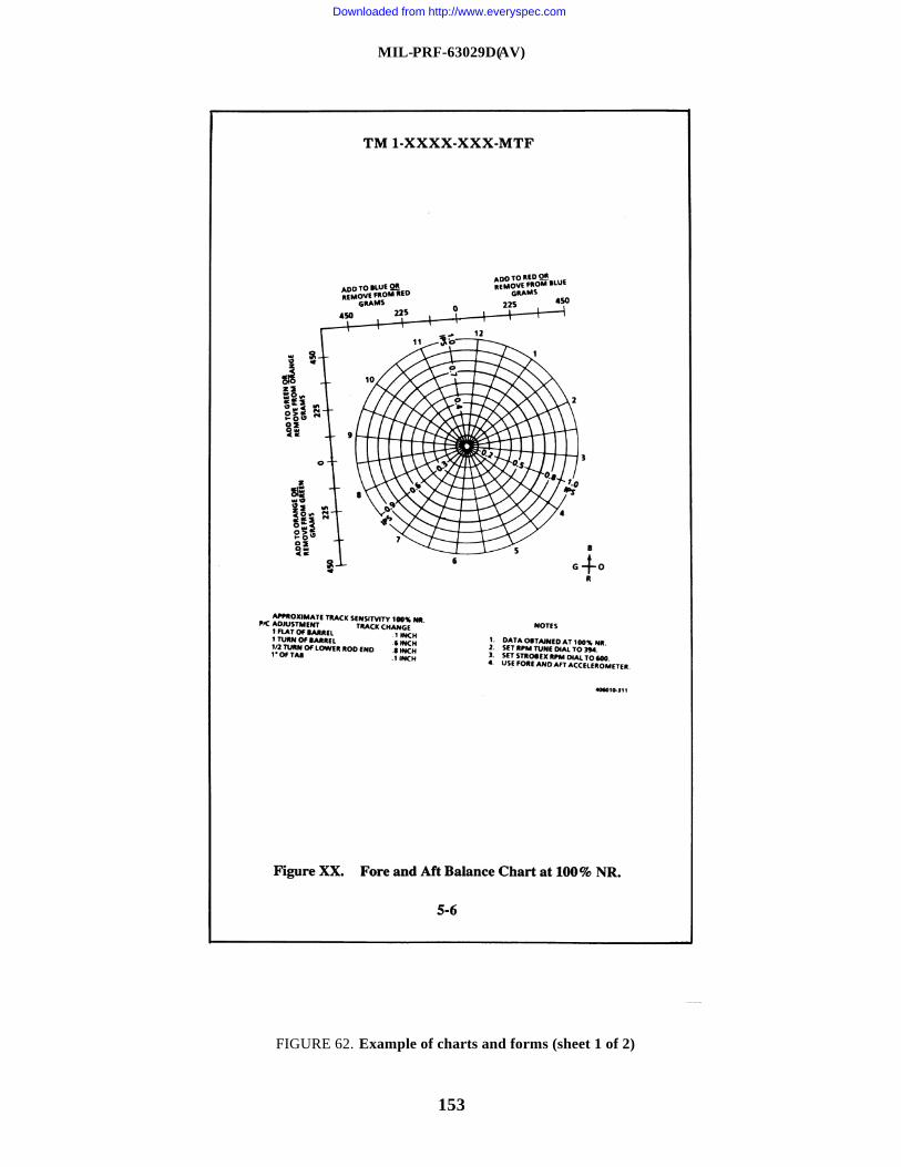
MIL-PRF-63029D(AV)
153
FIGURE 62. Example of charts and forms (sheet 1 of 2)
Downloaded from http://www.everyspec.com
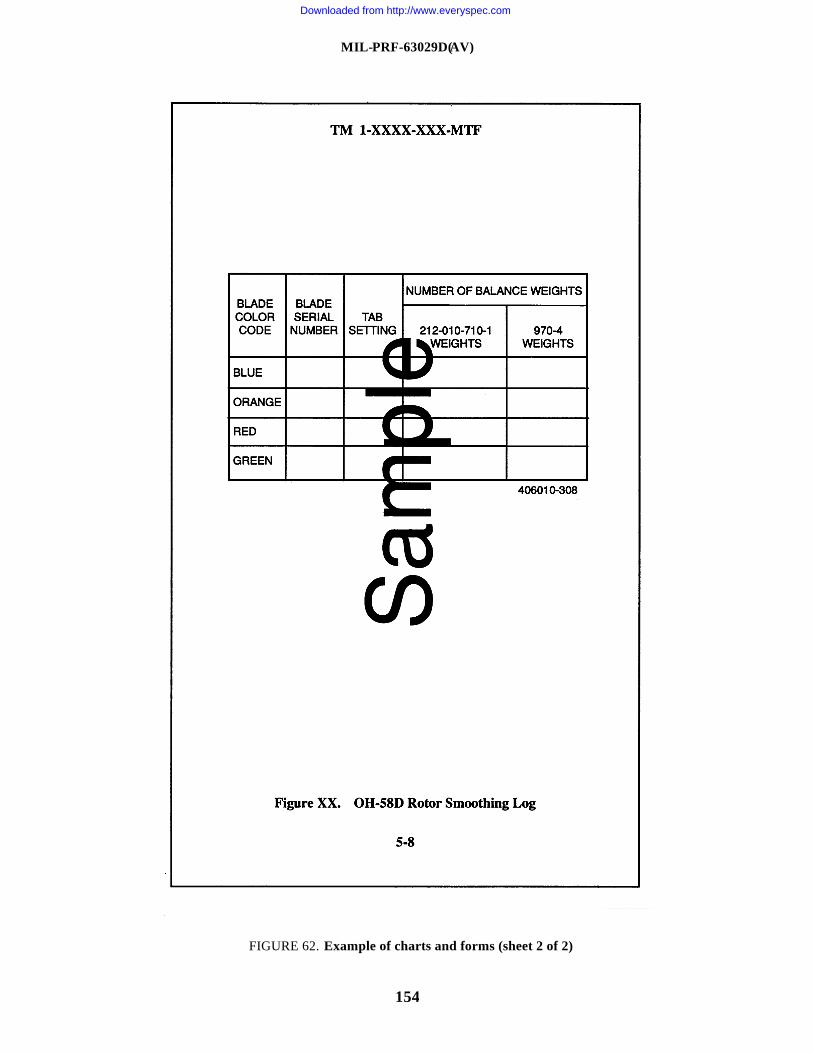
MIL-PRF-63029D(AV)
154
FIGURE 62. Example of charts and forms (sheet 2 of 2)
Downloaded from http://www.everyspec.com
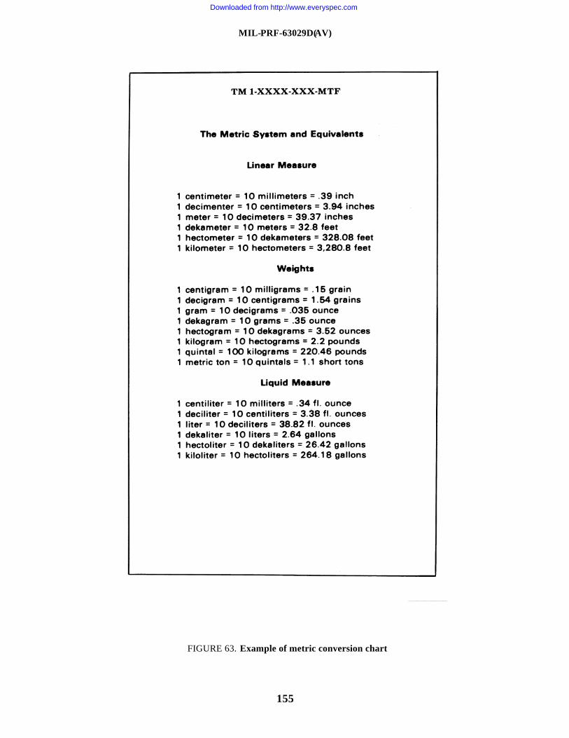
MIL-PRF-63029D(AV)
155
FIGURE 63. Example of metric conversion chart
Downloaded from http://www.everyspec.com
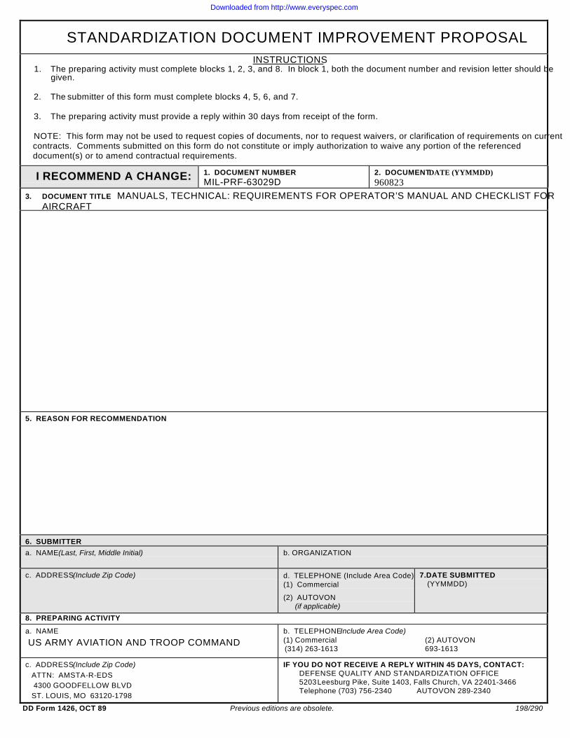
STANDARDIZATION DOCUMENT IMPROVEMENT PROPOSALINSTRUCTIONS
1. The preparing activity must complete blocks 1, 2, 3, and 8. In block 1, both the document number and revision letter should begiven.
2. The submitter of this form must complete blocks 4, 5, 6, and 7.
3. The preparing activity must provide a reply within 30 days from receipt of the form.
NOTE: This form may not be used to request copies of documents, nor to request waivers, or clarification of requirements on currentcontracts. Comments submitted on this form do not constitute or imply authorization to waive any portion of the referenceddocument(s) or to amend contractual requirements.
I RECOMMEND A CHANGE: 1. DOCUMENT NUMBERMIL-PRF-63029D
2. DOCUMENT DATE (YYMMDD)960823
3. DOCUMENT TITLE MANUALS, TECHNICAL: REQUIREMENTS FOR OPERATOR’S MANUAL AND CHECKLIST FORAIRCRAFT
5. REASON FOR RECOMMENDATION
6. SUBMITTERa. NAME (Last, First, Middle Initial) b. ORGANIZATION
c. ADDRESS (Include Zip Code) d. TELEPHONE (Include Area Code)(1) Commercial
(2) AUTOVON(if applicable)
7.DATE SUBMITTED(YYMMDD)
8. PREPARING ACTIVITY
a. NAME
US ARMY AVIATION AND TROOP COMMANDb. TELEPHONE Include Area Code)(1) Commercial (2) AUTOVON(314) 263-1613 693-1613
c. ADDRESS (Include Zip Code) ATTN: AMSTA-R-EDS 4300 GOODFELLOW BLVD ST. LOUIS, MO 63120-1798
IF YOU DO NOT RECEIVE A REPLY WITHIN 45 DAYS, CONTACT:DEFENSE QUALITY AND STANDARDIZATION OFFICE5203 Leesburg Pike, Suite 1403, Falls Church, VA 22401-3466Telephone (703) 756-2340 AUTOVON 289-2340
DD Form 1426, OCT 89 Previous editions are obsolete. 198/290
Downloaded from http://www.everyspec.com
Top Related