


Languages
Pages
Legal


Leitor Argox AI-6800O Leitor Argox AI-6800 é o primeiro scanner linear 1D do fabricante. Diferente dos leitores de códigos de barras industriais, inova com seu design mais elegante e ergonômico. Três vezes mais velocidade de transmissão de dados em comparação com outros scanners em sua classe.
www.bztech.com.br
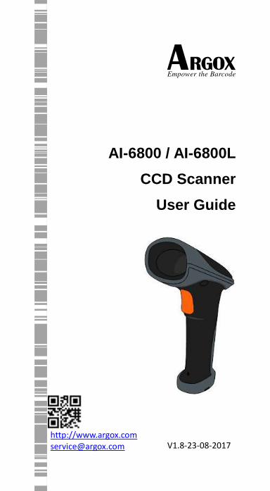
AI-6800 / AI-6800L
CCD Scanner
User Guide
http://www.argox.com [email protected] V1.8-23-08-2017
V1.0-23-08-2017
i
Regulatory Compliance
FEDERAL COMMUNICATIONS COMMISSION INTERFERENCE STATEMENT
This equipment has been tested and found to comply with the limits for a Class B digital device, pursuant to part 15 of the FCC Rules. These limits are designed to provide reasonable protection against harmful interference in a residential installation. This equipment generates, uses and can radiate radio frequency energy and, if not installed and used in accordance with the instructions, may cause harmful interference to radio communications. However, there is no guarantee that interference will not occur in a particular installation. If this equipment does cause harmful interference to radio or television reception, which can be determined by turning the equipment off and on, the user is encouraged to try to correct the interference by one or more of the following measures:
-Reorient or relocate the receiving antenna.
-Increase the separation between the equipment and receiver.
-Connect the equipment into an outlet on a circuit different from that to which the receiver is connected.
ii
-Consult the dealer or an experienced radio/ TV technician for help.
CAUTION:
Any changes or modifications not expressly
approved by the grantee of this device could void
the user's authority to operate the equipment.
RF exposure warning
The equipment complies with FCC RF
exposure limits set forth for an uncontrolled
environment.
The equipment must not be co-located or operating in conjunction with
any other antenna or transmitter.
RF EXPOSURE WARNING:
The equipment complies with FCC RF exposure limits
set forth for an uncontrolled environment.
The equipment must not be co-located or operating in conjunction with any other antenna or transmitter.
Note All brands and trademarks shall
belong to their respective owner.
Note Specification is subject to changes
without notice.
iii
Contents
1 Introduction .......................................................... 1 1.1 Unpacking ....................................................... 1 1.2 Understand your scanner ................................ 3
1.2.1 Scanner ..................................................... 3 1.2.2 Stand(optional accessory)......................... 4
1.3 Indicators......................................................... 5
1.3.1 Status lights ............................................... 5 1.3.2 Status sound ............................................. 5 1.3.3 Vibration ................................................... 5
2 Get started ............................................................ 6 2.1 Installation....................................................... 6
2.1.1 Set up your scanner .................................. 6 2.1.2 How to scan .............................................. 7
2.1.3 Work with the ASCII table ......................... 7 3 Controls and settings............................................. 8
3.1 Interface selection ......................................... 11 3.1.1 USB HID key board .................................. 12 3.1.2 RS-232 ..................................................... 15
3.2 Scan properties ............................................. 18 3.3 Indicator ........................................................ 23
3.4 Characters and strings (transmission) ........... 25 3.4.1 Prefix and suffix ...................................... 25 3.4.2 Preamble and postamble ........................ 26 3.4.3 String groups ........................................... 28
Example .................................................. 28 3.4.4 ID, name and capitalization .................... 32
3.5 Scanner information ...................................... 34
3.5.1 Parameters .............................................. 34
iv
3.5.2 Data Magic settings ................................ 35
3.5.3 Firmware version .................................... 35 3.6 Reset your scanner ........................................ 36 3.7 Update firmware ........................................... 37
Install driver ............................................ 45 3.8 Data Magic .................................................... 47
Data Magic commands ........................... 48 3.8.1 Bar code scanning ................................... 51
Data format ............................................. 51 Bar codes ................................................ 54 Example .................................................. 56
Scan Utility ........................................................ 61 Virtual COM ............................................ 65
4 Bar codes.. ........................................................... 67
UPC-A .................................................................. 67 UPC-E................................................................... 71 EAN-13 ................................................................ 75 EAN-8 .................................................................. 79 Code 39 ............................................................... 83 Interleaved 2 of 5 ................................................ 87 Industrial 2 of 5 ................................................... 89
Matrix 2 of 5 ........................................................ 91 Codabar ............................................................... 93 Code 128 / GS1-128 ............................................ 96 Code 93 ............................................................. 100 Code 11 ............................................................. 103 MSI/Plessey ....................................................... 105 UK/Plessey ........................................................ 107
Telepen .............................................................. 109 Standard 2 of 5 .................................................. 111
v
China Post ......................................................... 113
Italian Pharmacode (Code 32) ........................... 115 Code 16K ........................................................... 117 EAN UCC Composite .......................................... 119 GS1 Databar Omnidirectional ........................... 121 GS1 Databar Limited ......................................... 123 GS1 Databar Expanded...................................... 125
5 Troubleshooting ................................................ 127
5.1 Scanner issues ............................................. 127 5.2 Bar code issues ............................................ 127
6 Specifications .................................................... 129 Appendix A. Test symbologies .............................. 132 Appendix B. ASCII table ........................................ 135 Appendix C. Default settings of bar codes ............ 136
Appendix D. Data entry bar codes ........................ 138
1
1 Introduction
AI-6800/AI-6800L is a cord scanner that can
read bar codes on objects or on screens. The
high performance scanning engine delivers
high speed and high readability, making it an
ideal scanning solution for business.
■ High decoding performance Fast and easy scan for 1D bar codes.
■ Water resistant and dust-tight With the IP65 rating, AI-6800/AI-6800L can be used in various environment without being damaged by water and dust.
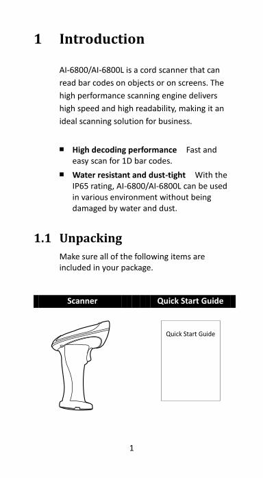
1.1 Unpacking
Make sure all of the following items are included in your package.
Scanner Quick Start Guide
2
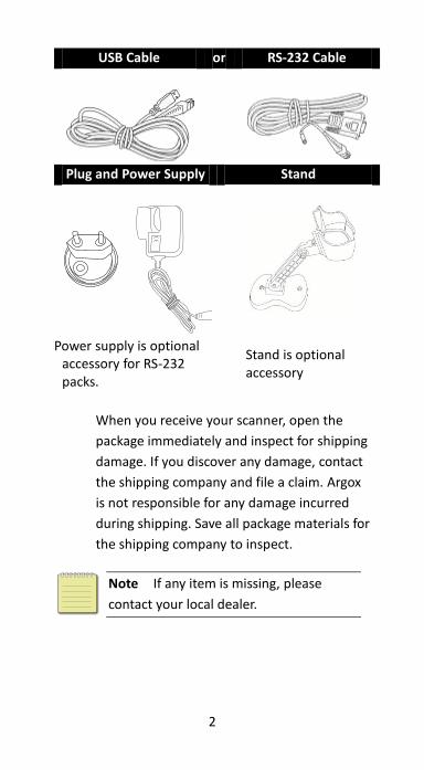
USB Cable or RS-232 Cable
Plug and Power Supply Stand
Power supply is optional accessory for RS-232 packs.
Stand is optional accessory
When you receive your scanner, open the
package immediately and inspect for shipping
damage. If you discover any damage, contact
the shipping company and file a claim. Argox
is not responsible for any damage incurred
during shipping. Save all package materials for
the shipping company to inspect.
Note If any item is missing, please
contact your local dealer.
3
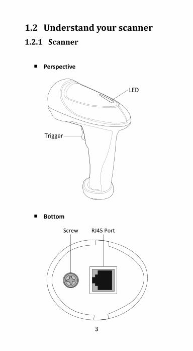
1.2 Understand your scanner
1.2.1 Scanner
■ Perspective
■ Bottom
4
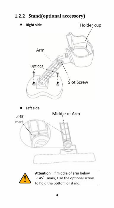
1.2.2 Stand(optional accessory)
■ Right side
■ Left side
Holder cup
Slot Screw
Attention : If middle of arm below ∠45∘mark, Use the optional screw
to hold the bottom of stand.
Optional
Arm
∠45∘
mark
Middle of Arm
5
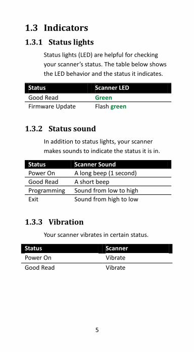
1.3 Indicators
1.3.1 Status lights
Status lights (LED) are helpful for checking
your scanner’s status. The table below shows
the LED behavior and the status it indicates.
Status Scanner LED
Good Read Green
Firmware Update Flash green
1.3.2 Status sound
In addition to status lights, your scanner
makes sounds to indicate the status it is in.
Status Scanner Sound
Power On A long beep (1 second)
Good Read A short beep
Programming Sound from low to high
Exit Sound from high to low
1.3.3 Vibration
Your scanner vibrates in certain status.
Status Scanner
Power On Vibrate
Good Read Vibrate
6
2 Get started
This chapter provides information about how
to install, connect and use your scanner to do
your work.
2.1 Installation
This section describes how to set up your scanner.
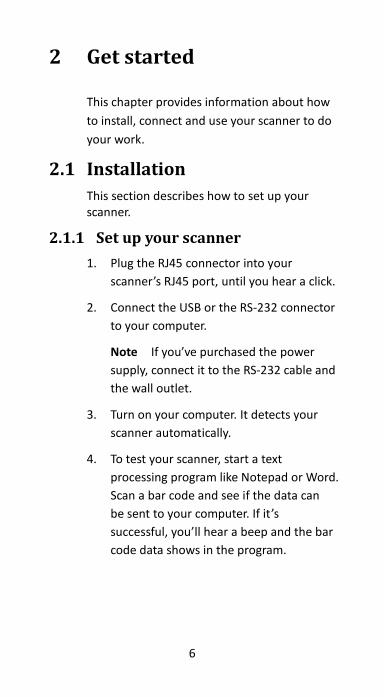
2.1.1 Set up your scanner
1. Plug the RJ45 connector into your
scanner’s RJ45 port, until you hear a click.
2. Connect the USB or the RS-232 connector
to your computer.
Note If you’ve purchased the power
supply, connect it to the RS-232 cable and
the wall outlet.
3. Turn on your computer. It detects your
scanner automatically.
4. To test your scanner, start a text
processing program like Notepad or Word.
Scan a bar code and see if the data can
be sent to your computer. If it’s
successful, you’ll hear a beep and the bar
code data shows in the program.
7
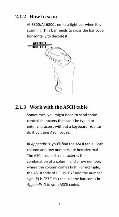
2.1.2 How to scan
AI-6800/AI-6800L emits a light bar when it is
scanning. This bar needs to cross the bar code
horizontally to decode it.
2.1.3 Work with the ASCII table
Sometimes, you might need to send some
control characters that can’t be typed or
enter characters without a keyboard. You can
do it by using ASCII codes.
In Appendix B, you'll find the ASCII table. Both
column and row numbers are hexadecimal.
The ASCII code of a character is the
combination of a column and a row number,
where the column comes first. For example,
the ASCII code of BEL is "07" and the number
sign (#) is "23." You can use the bar codes in
Appendix D to scan ASCII codes.
8
3 Controls and settings
Customize your scanner to work efficiently.
AI-6800/AI-6800L offers many features to
match your preferences. This chapter
provides information about how to change
controls and settings of your scanner.
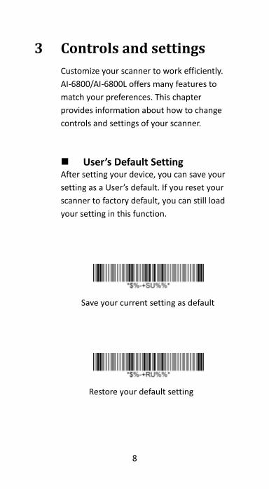
User’s Default Setting After setting your device, you can save your
setting as a User’s default. If you reset your
scanner to factory default, you can still load
your setting in this function.
Save your current setting as default
Restore your default setting
9
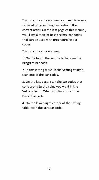
To customize your scanner, you need to scan a
series of programming bar codes in the
correct order. On the last page of this manual,
you’ll see a table of hexadecimal bar codes
that can be used with programming bar
codes.
To customize your scanner:
1. On the top of the setting table, scan the
Program bar code.
2. In the setting table, in the Setting column,
scan one of the bar codes.
3. On the last page, scan the bar codes that
correspond to the value you want in the
Value column. When you finish, scan the
Finish bar code.
4. On the lower-right corner of the setting
table, scan the Exit bar code.
10
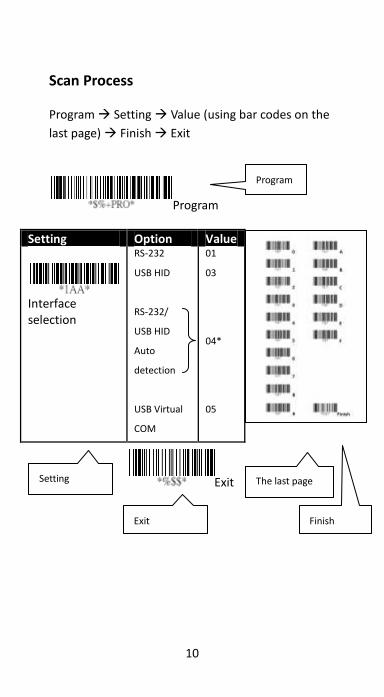
Scan Process Program Setting Value (using bar codes on the
last page) Finish Exit
Program
Setting Option Value
Interface selection
RS-232
USB HID
RS-232/
USB HID
Auto
detection
USB Virtual
COM
01
03
04*
05
Exit
Program
Setting
Exit
The last page
Finish
11
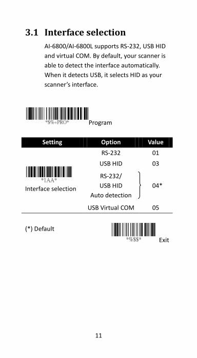
3.1 Interface selection
AI-6800/AI-6800L supports RS-232, USB HID
and virtual COM. By default, your scanner is
able to detect the interface automatically.
When it detects USB, it selects HID as your
scanner’s interface.
Program
Setting Option Value
Interface selection
RS-232 01
USB HID 03
RS-232/
USB HID
Auto detection
04*
USB Virtual COM 05
(*) Default
Exit

12
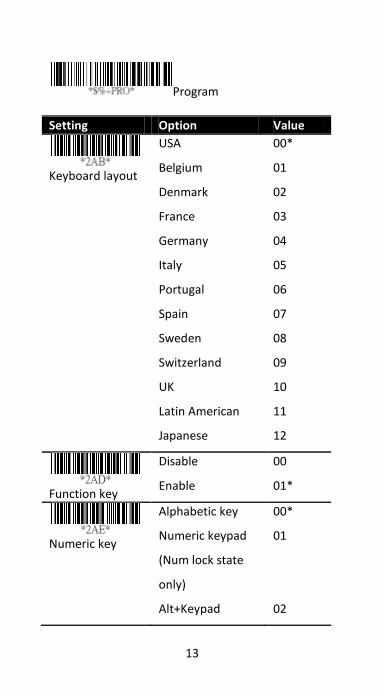
3.1.1 USB HID key board
Keyboard layout You can use it to change your
keyboard layout, so your scanner can scan bar
codes of different languages. Remember, you
also need to change your input method.
Function key It maps function keys to ASCII
codes, so you can scan bar codes in place of the
function key input. For example, if you scan the
numeric bar code “1” and then “2,” your scanner
sends the specific character to your computer as
though you press F2. The code mapping range is
from 01 to 1F. For more information about ASCII
codes, see ASCII table in Appendix B.
Numeric key The keypad is located to the
rightmost of a keyboard. You need to select this
mode if your program only accepts numerals.
When selecting Alt+Keypad, your bar code data
will be sent as if you’re pressing “Alt+number.” It
is useful when your bar code contains a special
character, such as the Euro sign (€).
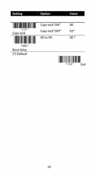
Caps lock It determines whether the state of
the Caps Lock key affects the output of bar
codes.
Block Delay It is a delay timer between barcode data
output. The feature is used to transfer continually with
shorter barcode data or multi-field scanning.
13
Program
Setting Option Value
Keyboard layout
USA
Belgium
Denmark
France
Germany
Italy
Portugal
Spain
Sweden
Switzerland
UK
Latin American
Japanese
00*
01
02
03
04
05
06
07
08
09
10
11
12
Function key
Disable
Enable
00
01*
Numeric key
Alphabetic key
Numeric keypad
(Num lock state
only)
Alt+Keypad
00*
01
02
14
Setting Option Value
Caps lock
Caps lock”ON”
Caps lock”OFF”
00
01*
*3AC*
Block Delay
00 to 99.
00 *
(*) Default
Exit
15
3.1.2 RS-232
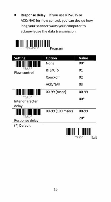
Flow control
• None Your computer and scanner only
use TxD and RxD signals for
communication. No hardware or software
flow control is used.
• RTS/CTS It is hardware flow control. If
your scanner is ready to send bar code
data to your computer, it sends an RTS
signal, and waits to receive a CTS signal
from your computer. If your scanner
doesn’t receive a CTS after a timeout,
you’ll hear five warning beeps from it.
• Xon/Xoff It is software flow control.
When your computer is unable to receive
data, it sends an Xoff signal to notify your
scanner to stop sending data; it sends an
Xon signal when it’s ready.
• ACK/NAK Your scanner sends data after
it received an ACK signal from your
computer, and will resend data if it
receives an NAK signal.
Inter-character delay It determines how fast
your computer receives each character and
displays it on the screen. If the speed is set too
fast and your computer system is slow, your
computer may lose data.
16
Response delay If you use RTS/CTS or
ACK/NAK for flow control, you can decide how
long your scanner waits your computer to
acknowledge the data transmission.
Program
Setting Option Value
Flow control
None
RTS/CTS
Xon/Xoff
ACK/NAK
00*
01
02
03
Inter-character delay
00-99 (msec) 00-99
00*
Response delay
00-99 (100 msec) 00-99
20*
(*) Default
Exit
17
Exit
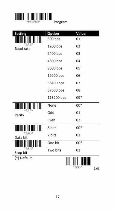
Program
Setting Option Value
Baud rate
600 bps
1200 bps
2400 bps
4800 bps
9600 bps
19200 bps
38400 bps
57600 bps
115200 bps
01
02
03
04
05
06
07
08
09*
Parity
None
Odd
Even
00*
01
02
Data bit
8 bits
7 bits
00*
01
Stop bit
One bit
Two bits
00*
01
(*) Default
18
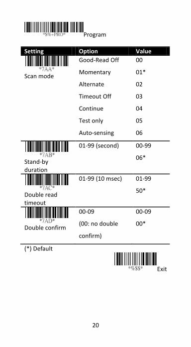
3.2 Scan properties
■ Good-read off After you pull the trigger, your
scanner will keep emitting the light bar, until it
captures a good scan or no bar code is decoded
after the stand-by duration elapsed.
■ Momentary When you pull the trigger, the
light bar is turned on; when you release the
trigger, the light bar is turned off.
■ Alternate The trigger acts as a toggle. When
you pull the trigger, the light bar is turned on;
when you pull it again, the light bar is turned off.
■ Timeout-off When you pull the trigger, the
light bar is turned on. If no bar code is decoded
after the stand-by duration elapsed, the light bar
is turned off.
■ Continue It automatically detects and decodes
bar codes in your scanner’s field of view. You can
turn on this mode when you want to decode bar
codes without pulling the trigger. If no bar code
is decoded after the stand-by duration elapsed,
the light bar will flash. You can move your
scanner or pull the trigger to wake it up.
■ Test only It is reserved for engineers to test.
■ Auto-sensing Similar to Continue, it
automatically detects and decodes bar codes in
your scanner’s field of view. If no bar code is
decoded after the stand-by duration elapsed,
the light bar will be turned off. You can move
your scanner or pull the trigger to wake it up.
■ Double read timeout It determines the
duration of Double confirm. For example, if you
19
set 5 times in Double confirm and set 10
milliseconds in Double read timeout, the
decoder will decode a bar code 5 times in 10
milliseconds. You need to turn on Double
confirm to use this feature.
■ Double confirm It determines how many times
the decoder needs to confirm a bar code.
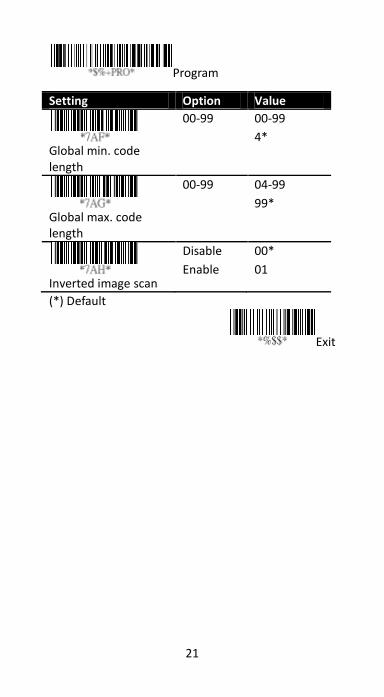
■ Global min/max code length The min and max
code length defines the decoding length of all
bar codes. Note the following when you set their
length:
• If the length of a bar code is shorter than
the min or longer than the max, the bar
code won’t be decoded.
• If the min is equal to the max, the decoding
length is fixed.
• Some bar codes have their own decoding
length. If you set the individual min or max
decoding length for a bar code, your scanner
will go by the individual setting.
■ Inverted image scan When you turn on this
feature, you can scan both regular and inverted
bar codes.
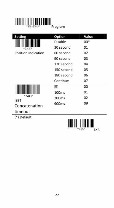
■ Position indication When you turn on this
feature, the light bar keeps flashing. This feature
determines how long the light bar flashes.
■ ISBT Concatenation timeout when scanning
single ISBT barcode, scanner will wait 900ms to
output barcode because it is seeking appended
ISBT barcode until timeout.
20
Program
Setting Option Value
Scan mode
Good-Read Off
Momentary
Alternate
Timeout Off
Continue
Test only
Auto-sensing
00
01*
02
03
04
05
06
Stand-by duration
01-99 (second) 00-99
06*
Double read timeout
01-99 (10 msec) 01-99
50*
Double confirm
00-09
(00: no double
confirm)
00-09
00*
(*) Default
Exit
21
Program
Setting Option Value
Global min. code length
00-99 00-99
4*
Global max. code length
00-99 04-99
99*
Inverted image scan
Disable
Enable
00*
01
(*) Default
Exit
22
Program
Setting Option Value
Position indication
Disable
30 second
60 second
90 second
120 second
150 second
180 second
Continue
00*
01
02
03
04
05
06
07
*7AO*
ISBT
Concatenation timeout
關
100ms
200ms
900ms
00
01
02
09
(*) Default
Exit
23
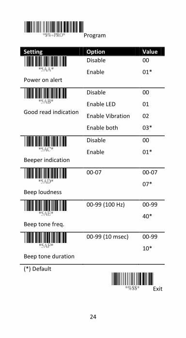
3.3 Indicator
■ Power on alert When your scanner is turned
on, you’ll hear a long beep.
■ Good read indication The reation after your
scanner gets a good read.
■ Beeper indication Your scanner will beep after
it gets a good read.
■ Beep loudness It is the volume of the good
read beep. The bigger the number, the higher
the volume.
■ Beep tone freq It is the tone of the good read
beep. The bigger the number, the higher the
tone.
■ Beep tone duration It is the duration of the
good read beep. The bigger the number, the
longer the duration.
24
Program
Setting Option Value
Power on alert
Disable
Enable
00
01*
Good read indication
Disable
Enable LED
Enable Vibration
Enable both
00
01
02
03*
Beeper indication
Disable
Enable
00
01*
Beep loudness
00-07 00-07
07*
Beep tone freq.
00-99 (100 Hz) 00-99
40*
Beep tone duration
00-99 (10 msec) 00-99
10*
(*) Default
Exit
25
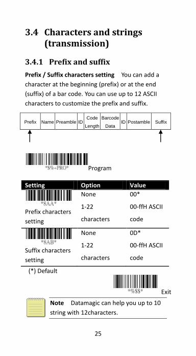
3.4 Characters and strings (transmission)
3.4.1 Prefix and suffix
Prefix / Suffix characters setting You can add a
character at the beginning (prefix) or at the end
(suffix) of a bar code. You can use up to 12 ASCII
characters to customize the prefix and suffix.
Prefix Name Preamble ID Code
Length
Barcode
Data ID Postamble Suffix
Program
Setting Option Value
Prefix characters
setting
None
1-22
characters
00*
00-ffH ASCII
code
Suffix characters
setting
None
1-22
characters
0D*
00-ffH ASCII
code
(*) Default
Exit
Note Datamagic can help you up to 10
string with 12characters.
26
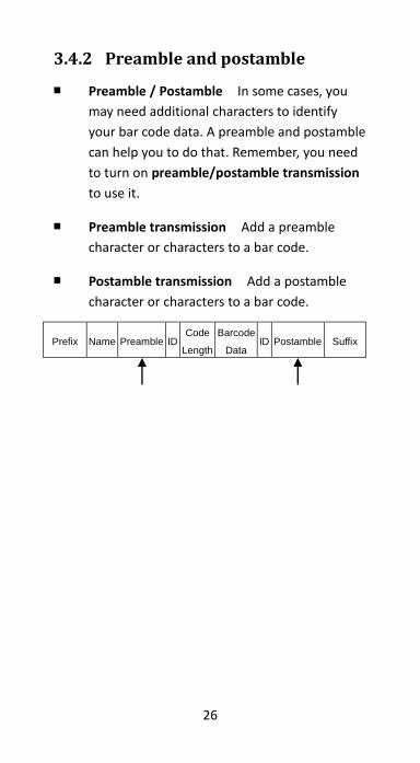
3.4.2 Preamble and postamble
■ Preamble / Postamble In some cases, you
may need additional characters to identify
your bar code data. A preamble and postamble
can help you to do that. Remember, you need
to turn on preamble/postamble transmission
to use it.
■ Preamble transmission Add a preamble
character or characters to a bar code.
■ Postamble transmission Add a postamble
character or characters to a bar code.
Prefix Name Preamble ID Code
Length
Barcode
Data ID Postamble Suffix
27
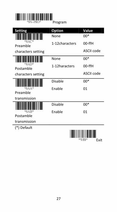
Program
Setting Option Value
Preamble
characters setting
None
1-12characters
00*
00-ffH
ASCII code
Postamble
characters setting
None
1-12haracters
00*
00-ffH
ASCII code
Preamble
transmission
Disable
Enable
00*
01
Postamble
transmission
Disable
Enable
00*
01
(*) Default
Exit
28
3.4.3 String groups
■ Insert G1/G2/G3/G4 character setting
You can insert up to two strings into a bar
code. Each string can contain up to 12
characters. First, you need to set a string
in a group, and then insert the group into
your bar code. There are four string
groups. You can decide which group you
want to use and where you want to insert
it. You can insert the same group two
times if you want.
Note if you want to insert G5-G10, use
Data Magic.
■ Insert data group position It
determines the position that the string
group will be inserted into. Note that the
insertion position can't exceed the length
of a bar code, or the group will be
inserted at the end of the bar code. The
value “00” inserts the group at the
beginning of a bar code, and “64” inserts
the group at the end of a bar code.
Example
To insert a string group into a bar code:
Step 1. Set a string in a group.
1. Scan the Program and Insert G1
characters setting bar codes.
2. In the ASCII code table, find the value of
the character you want to insert. For
29
example, if you want to insert the string
"AB," you'll find A→41, B→42.
3. On the last page, scan "41" and "42," and
then scan the Finish bar code.
4. Scan the Exit bar code.
Step 2. Insert the string into the specified
position.
1. Scan the Program and Insert data group
1 position bar codes.
2. On the last page, scan “03,” and then
scan the Finish bar code. This means
we’re inserting the string into the third
position of a bar code.
3. Scan the Exit bar code.
Step 3. Specify the bar code you want to
insert.
1. We’re using Code 128 as an example. In
the section Code 128, scan the Program
and Insert group number selection bar
codes.
2. On the last page, scan “01,” and then
scan the Finish bar code. This means
we’re inserting Group1 into a Code 128
bar code.
3. Scan the Exit bar code.
Original data: 258963
Result: 258AB963
30
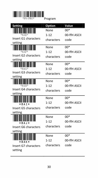
Program
Setting Option Value
Insert G1 characters setting
None
1-12
characters
00*
00-ffH ASCII
code
Insert G2 characters setting
None
1-12
characters
00*
00-ffH ASCII
code
Insert G3 characters setting
None
1-12
characters
00*
00-ffH ASCII
code
Insert G4 characters setting
None
1-12
characters
00*
00-ffH ASCII
code
Insert G5 characters setting
None
1-12
characters
00*
00-ffH ASCII
code
Insert G6 characters setting
None
1-12
characters
00*
00-ffH ASCII
code
Insert G7 characters setting
None
1-12
characters
00*
00-ffH ASCII
code
31
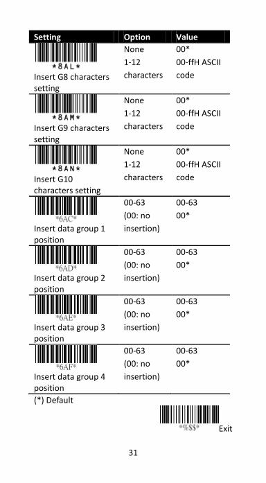
Setting Option Value
Insert G8 characters setting
None
1-12
characters
00*
00-ffH ASCII
code
Insert G9 characters setting
None
1-12
characters
00*
00-ffH ASCII
code
Insert G10 characters setting
None
1-12
characters
00*
00-ffH ASCII
code
Insert data group 1 position
00-63
(00: no
insertion)
00-63
00*
Insert data group 2 position
00-63
(00: no
insertion)
00-63
00*
Insert data group 3 position
00-63
(00: no
insertion)
00-63
00*
Insert data group 4 position
00-63
(00: no
insertion)
00-63
00*
(*) Default
Exit

32
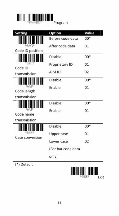
3.4.4 ID, name and capitalization
■ Code ID position You can choose to
place Code ID before or after a bar code.
Prefix Name Preamble ID Code
Length
Barcode
Data ID Postamble Suffix
■ Code ID transmission Code ID is an
identifier for a bar code. It has two modes:
Proprietary ID or AIM ID. You can choose
either of them. If you want to customize
the code ID using an ASCII code, you need
to choose Proprietary ID. AIM ID is fixed
since it is defined by the AIM organization.
■ Code length transmission It shows the
length of a bar code at its beginning. For
example, if your bar code is "258963," the
result will be "06258963,” in which 06 is
the length.
■ Code name transmission It shows the
name of a bar code type at the beginning
of a bar code. For example, if your bar
code type is Code 39, and your bar code is
“09741258R,” the result is “(Code-39) 09741258R.”
■ Case conversion You can change the
capitalization of letters. For example, if you
choose Upper case, the string “12aBcDeF”
will be converted to “12ABCDEF.”
33
Program
Setting Option Value
Code ID position
Before code data
After code data
00*
01
Code ID
transmission
Disable
Proprietary ID
AIM ID
00*
01
02
Code length
transmission
Disable
Enable
00*
01
Code name
transmission
Disable
Enable
00*
01
Case conversion
Disable
Upper case
Lower case
(For bar code data
only)
00*
01
02
(*) Default
Exit
34
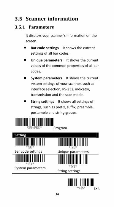
3.5 Scanner information
3.5.1 Parameters
It displays your scanner’s information on the
screen.
■ Bar code settings It shows the current
settings of all bar codes.
■ Unique parameters It shows the current
values of the common properties of all bar
codes.
■ System parameters It shows the current
system settings of your scanner, such as
interface selection, RS-232, indicator,
transmission and the scan mode.
■ String settings It shows all settings of
strings, such as prefix, suffix, preamble,
postamble and string groups.
Program
Setting
Bar code settings
Unique parameters
System parameters
String settings
Exit
35
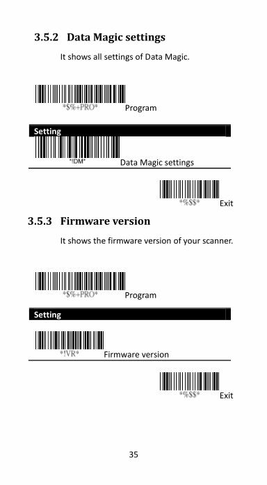
3.5.2 Data Magic settings
It shows all settings of Data Magic.
Program
Setting
Data Magic settings
Exit
3.5.3 Firmware version
It shows the firmware version of your scanner.
Program
Setting
Firmware version
Exit
36
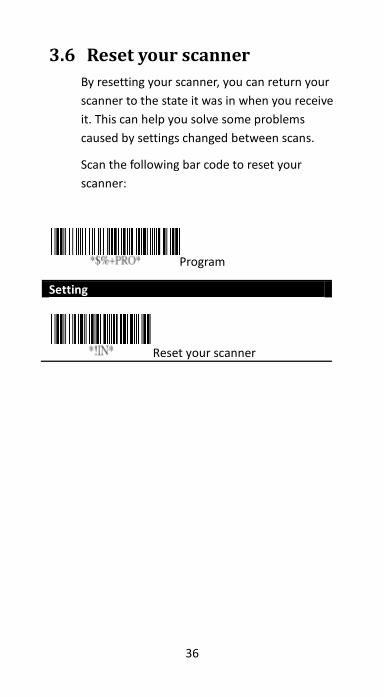
3.6 Reset your scanner
By resetting your scanner, you can return your
scanner to the state it was in when you receive
it. This can help you solve some problems
caused by settings changed between scans.
Scan the following bar code to reset your
scanner:
Program
Setting
Reset your scanner
37
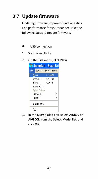
3.7 Update firmware
Updating firmware improves functionalities
and performance for your scanner. Take the
following steps to update firmware.
USB connection
1. Start Scan Utility.
2. On the File menu, click New.
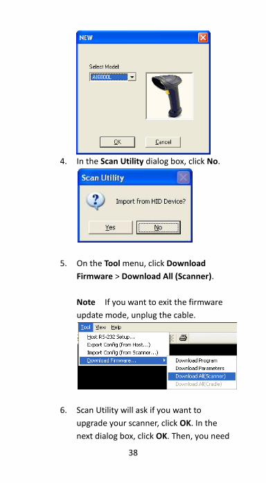
3. In the NEW dialog box, select AI6800 or
AI6800L from the Select Model list, and
click OK.
38
4. In the Scan Utility dialog box, click No.
5. On the Tool menu, click Download
Firmware > Download All (Scanner).
Note If you want to exit the firmware
update mode, unplug the cable.
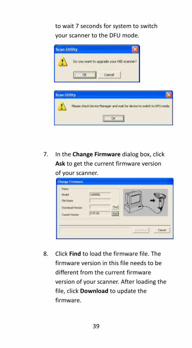
6. Scan Utility will ask if you want to
upgrade your scanner, click OK. In the
next dialog box, click OK. Then, you need
39
to wait 7 seconds for system to switch
your scanner to the DFU mode.
7. In the Change Firmware dialog box, click
Ask to get the current firmware version
of your scanner.
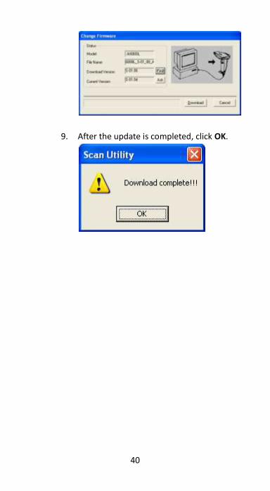
8. Click Find to load the firmware file. The
firmware version in this file needs to be
different from the current firmware
version of your scanner. After loading the
file, click Download to update the
firmware.
40
9. After the update is completed, click OK.
41
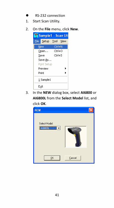
RS-232 connection
1. Start Scan Utility.
2. On the File menu, click New.
3. In the NEW dialog box, select AI6800 or
AI6800L from the Select Model list, and
click OK.
42
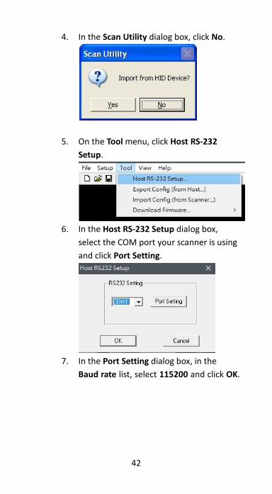
4. In the Scan Utility dialog box, click No.
5. On the Tool menu, click Host RS-232
Setup.
6. In the Host RS-232 Setup dialog box,
select the COM port your scanner is using
and click Port Setting.
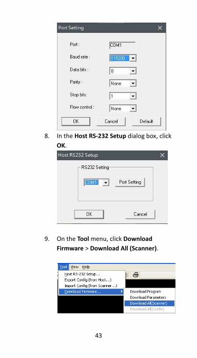
7. In the Port Setting dialog box, in the
Baud rate list, select 115200 and click OK.
43
8. In the Host RS-232 Setup dialog box, click
OK.
9. On the Tool menu, click Download
Firmware > Download All (Scanner).
44
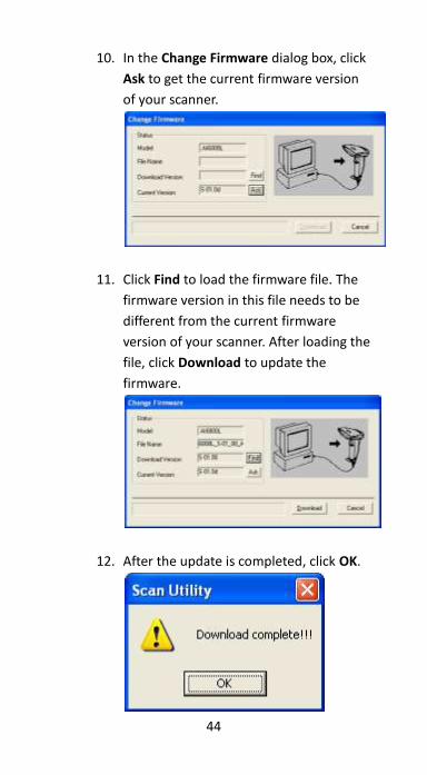
10. In the Change Firmware dialog box, click
Ask to get the current firmware version
of your scanner.
11. Click Find to load the firmware file. The
firmware version in this file needs to be
different from the current firmware
version of your scanner. After loading the
file, click Download to update the
firmware.
12. After the update is completed, click OK.
45
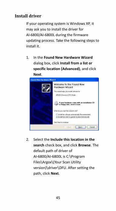
Install driver
If your operating system is Windows XP, it
may ask you to install the driver for
AI-6800/AI-6800L during the firmware
updating process. Take the following steps to
install it.
1. In the Found New Hardware Wizard
dialog box, click Install from a list or
specific location (Advanced), and click
Next.
2. Select the Include this location in the
search check box, and click Browse. The
default path of driver of
AI-6800/AI-6800L is C:\Program
Files\Argox\(Your Scan Utility
version)\driver\DFU. After setting the
path, click Next.

46
3. The system starts to install the driver.
After it is completed, click Finish.
47
3.8 Data Magic
Data Magic offers 10 commands for you to
customize text strings of bar codes. Each
command can be specified in a rule. Data
Magic allows up to 10 rules to be applied.
With the flexibility Data Magic provides, you
can define data as you want.
There are two ways to use Data Magic:
scanning bar codes, or using Scan Utility. By
scanning bar codes, you can quickly change
the settings without using programs; by using
Scan Utility, you can see the settings at a
glance and change them through the
easy-operated user interface. Choose the
method that meets your need.
Important Data Magic default is disabled. To enable Data Magic function, go to chapter 4 Bar codes and find Data Magic column to enable it.
48
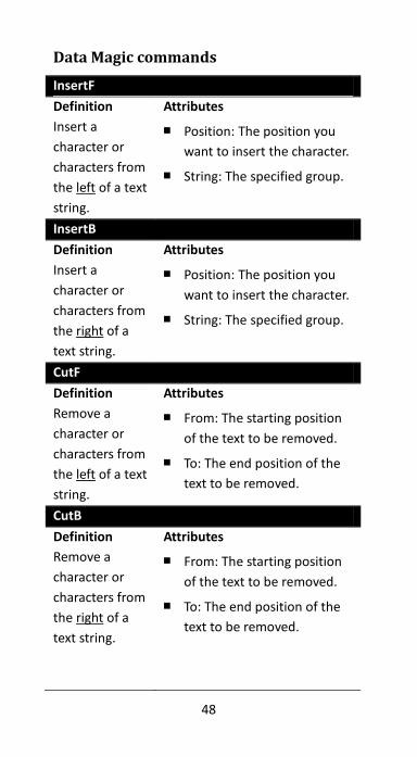
Data Magic commands
InsertF
Definition
Insert a
character or
characters from
the left of a text
string.
Attributes
■ Position: The position you
want to insert the character.
■ String: The specified group.
InsertB
Definition
Insert a
character or
characters from
the right of a
text string.
Attributes
■ Position: The position you
want to insert the character.
■ String: The specified group.
CutF
Definition
Remove a
character or
characters from
the left of a text
string.
Attributes
■ From: The starting position
of the text to be removed.
■ To: The end position of the
text to be removed.
CutB
Definition
Remove a
character or
characters from
the right of a
text string.
Attributes
■ From: The starting position
of the text to be removed.
■ To: The end position of the
text to be removed.
49
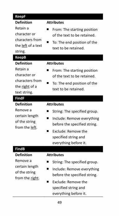
KeepF
Definition
Retain a
character or
characters from
the left of a text
string.
Attributes
■ From: The starting position
of the text to be retained.
■ To: The end position of the
text to be retained.
KeepB
Definition
Retain a
character or
characters from
the right of a
text string.
Attributes
■ From: The starting position
of the text to be retained.
■ To: The end position of the
text to be retained.
FindF
Definition
Remove a
certain length
of the string
from the left.
Attributes
■ String: The specified group.
■ Include: Remove everything
before the specified string.
■ Exclude: Remove the
specified string and
everything before it.
FindB
Definition
Remove a
certain length
of the string
from the right.
Attributes
■ String: The specified group.
■ Include: Remove everything
before the specified string.
■ Exclude: Remove the
specified string and
everything before it.
50
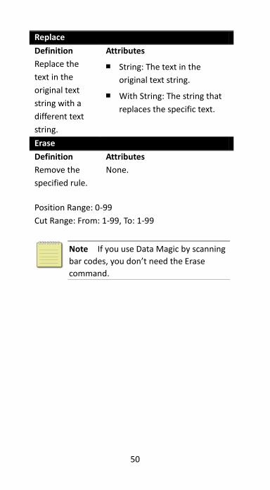
Replace
Definition
Replace the
text in the
original text
string with a
different text
string.
Attributes
■ String: The text in the
original text string.
■ With String: The string that
replaces the specific text.
Erase
Definition
Remove the
specified rule.
Attributes
None.
Position Range: 0-99
Cut Range: From: 1-99, To: 1-99
Note If you use Data Magic by scanning
bar codes, you don’t need the Erase
command.

51
3.8.1 Bar code scanning
Bar code scanning is a quick way to work with
Data Magic. Just scan the bar codes in specific
order, and you can customize your string in
seconds.
Data format
Data Magic provides 10 rules for you to set.
To set a rule, follow this data format to scan
bar codes:
Program + Rule + Command + Attribute 1 + Attribute 2 + Finish + Exit

52
Item Description
Rule
The rule number. The lower
the number, the higher the
priority. The rule with the high
priority will be applied first.
Command The command you specify in
the rule.
Attribute 1 The attribute varies according
to the command.
Attribute 2 The attribute varies according
to the command.
Command Attribute 1 Attribute 2
InsertF Position String
InsertB Position String
CutF From To
CutB From To
KeepF From To
KeepB From To
FindF String Include or
Exclude
FindB String Include or
Exclude
Replace String With String
Erase - -
53
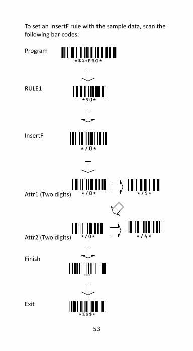
To set an InsertF rule with the sample data, scan the following bar codes: Program
RULE1
InsertF
Attr1 (Two digits)
Attr2 (Two digits)
Finish
Exit
54
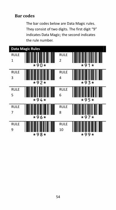
Bar codes
The bar codes below are Data Magic rules.
They consist of two digits. The first digit “9”
indicates Data Magic; the second indicates
the rule number.
Data Magic Rules
RULE
1
RULE
2
RULE
3
RULE
4
RULE
5
RULE
6
RULE
7
RULE
8
RULE
9
RULE
10
55
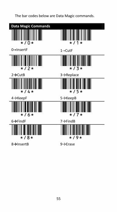
The bar codes below are Data Magic commands.
Data Magic Commands
0→InsertF
1→CutF
2→CutB
3→Replace
4→KeepF
5→KeepB
6→FindF
7→FindB
8→InsertB
9→Erase
56
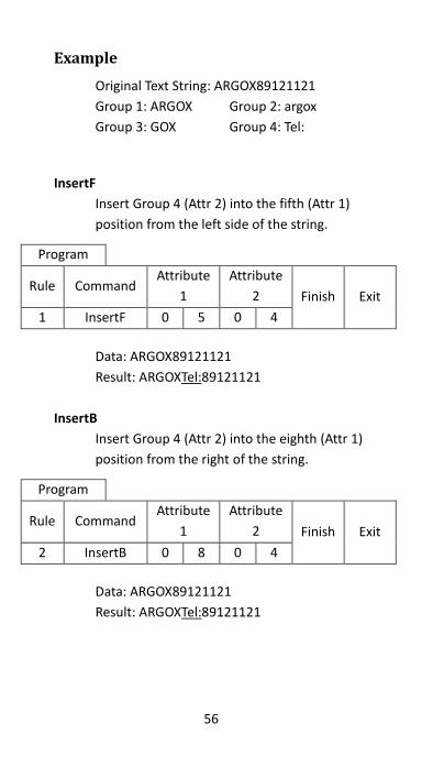
Example
Original Text String: ARGOX89121121
Group 1: ARGOX Group 2: argox
Group 3: GOX Group 4: Tel:
InsertF
Insert Group 4 (Attr 2) into the fifth (Attr 1)
position from the left side of the string.
Program
Rule Command Attribute
1
Attribute
2 Finish Exit
1 InsertF 0 5 0 4
Data: ARGOX89121121
Result: ARGOXTel:89121121
InsertB
Insert Group 4 (Attr 2) into the eighth (Attr 1)
position from the right of the string.
Program
Rule Command Attribute
1
Attribute
2 Finish Exit
2 InsertB 0 8 0 4
Data: ARGOX89121121
Result: ARGOXTel:89121121
57
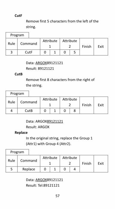
CutF
Remove first 5 characters from the left of the
string.
Program
Rule Command Attribute
1
Attribute
2 Finish Exit
3 CutF 0 1 0 5
Data: ARGOX89121121
Result: 89121121
CutB
Remove first 8 characters from the right of
the string.
Program
Rule Command Attribute
1
Attribute
2 Finish Exit
4 CutB 0 1 0 8
Data: ARGOX89121121
Result: ARGOX
Replace
In the original string, replace the Group 1
(Attr1) with Group 4 (Attr2).
Program
Rule Command Attribute
1
Attribute
2 Finish Exit
5 Replace 0 1 0 4
Data: ARGOX89121121
Result: Tel:89121121
58
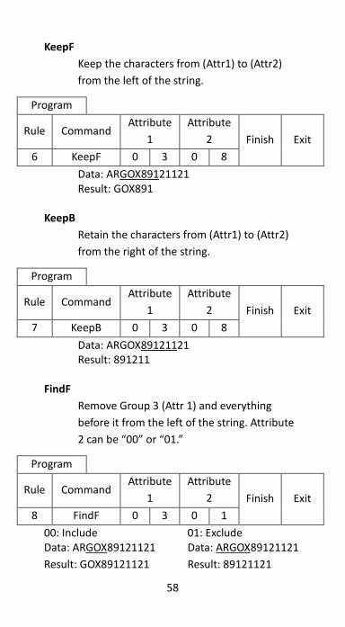
KeepF
Keep the characters from (Attr1) to (Attr2)
from the left of the string.
Program
Rule Command Attribute
1
Attribute
2 Finish Exit
6 KeepF 0 3 0 8
Data: ARGOX89121121 Result: GOX891
KeepB
Retain the characters from (Attr1) to (Attr2)
from the right of the string.
Program
Rule Command Attribute
1
Attribute
2 Finish Exit
7 KeepB 0 3 0 8
Data: ARGOX89121121 Result: 891211
FindF
Remove Group 3 (Attr 1) and everything
before it from the left of the string. Attribute
2 can be “00” or “01.”
Program
Rule Command Attribute
1
Attribute
2 Finish Exit
8 FindF 0 3 0 1
00: Include 01: Exclude Data: ARGOX89121121 Data: ARGOX89121121
Result: GOX89121121 Result: 89121121

59
FindB
Remove Group 3 (Attr 1) and everything
before it from the right of the string. Attribute
2 can be “00” or “01.”
Program
Rule Command Attribute
1
Attribute
2 Finish Exit
9 FindB 0 3 0 1
00: Include 01: Exclude
Data: ARGOX89121121 Data: ARGOX89121121
Result: ARGOX Result: AR
Erase
Remove the specified rule.
Program Rule Command
Exit Rule 10 Erase

60
Erase
To remove all values in Data Magic, scan the
bar code below.
Display the current settings To display the current settings of Data Magic,
scan the following bar codes:
Program
Display Data Magic
settings
OR
Displays Inserted
Group settings
61
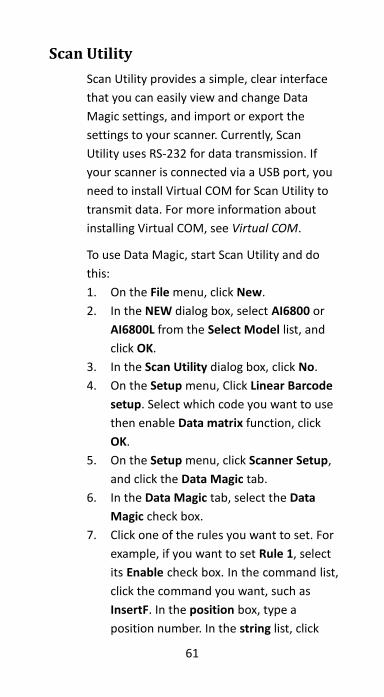
Scan Utility
Scan Utility provides a simple, clear interface
that you can easily view and change Data
Magic settings, and import or export the
settings to your scanner. Currently, Scan
Utility uses RS-232 for data transmission. If
your scanner is connected via a USB port, you
need to install Virtual COM for Scan Utility to
transmit data. For more information about
installing Virtual COM, see Virtual COM.
To use Data Magic, start Scan Utility and do
this:
1. On the File menu, click New.
2. In the NEW dialog box, select AI6800 or
AI6800L from the Select Model list, and
click OK.
3. In the Scan Utility dialog box, click No.
4. On the Setup menu, Click Linear Barcode
setup. Select which code you want to use
then enable Data matrix function, click
OK.
5. On the Setup menu, click Scanner Setup,
and click the Data Magic tab.
6. In the Data Magic tab, select the Data
Magic check box.
7. Click one of the rules you want to set. For
example, if you want to set Rule 1, select
its Enable check box. In the command list,
click the command you want, such as
InsertF. In the position box, type a
position number. In the string list, click
62
the group you want.
8. Repeat the previous step until you set all
the rules you need, and click the String
tab.
9. In the String tab, there are 10 string
boxes: Insert G1-G10 chars setting. Each
box corresponds to the group you’ve
selected in the string list in the Data
Magic tab. Depending on your selection,
type the text you want in the specific box.
For example, if you’ve selected Group1,
type in the Insert G1 chars setting box.
The string box accepts up to 12
single-byte characters. When you’re done,
click OK.
10. On the Tool menu, click Export Config
(from Host), and click Export. If the data
is exported successfully, you’ll hear a long
beep.
63
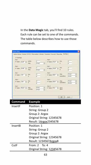
In the Data Magic tab, you’ll find 10 rules.
Each rule can be set to one of the commands.
The table below describes how to use those
commands.
Command Example
InsertF Position: 1 String: Group 2 Group 2: Argox Original String: 12345678 Result: 1Argox2345678
InsertB Position: 1 String: Group 2 Group 2: Argox Original String: 12345678 Result: 1234567Argox8
CutF From: 2 To: 4 Original String: 12345678
64
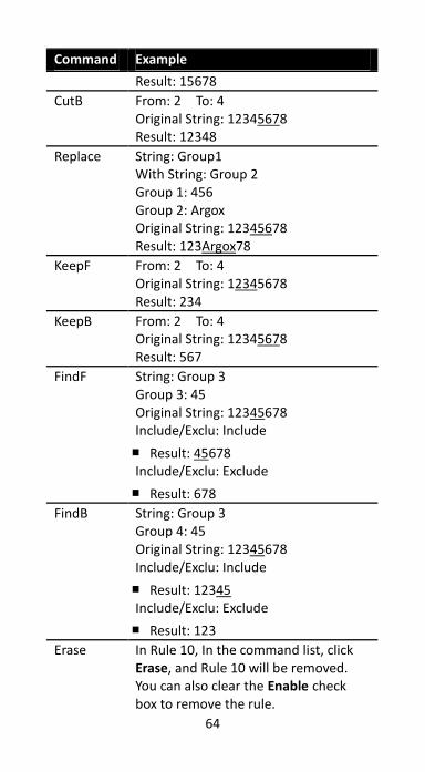
Command Example
Result: 15678
CutB From: 2 To: 4 Original String: 12345678 Result: 12348
Replace String: Group1 With String: Group 2 Group 1: 456 Group 2: Argox Original String: 12345678 Result: 123Argox78
KeepF From: 2 To: 4 Original String: 12345678 Result: 234
KeepB From: 2 To: 4 Original String: 12345678 Result: 567
FindF String: Group 3 Group 3: 45 Original String: 12345678 Include/Exclu: Include
■ Result: 45678 Include/Exclu: Exclude
■ Result: 678
FindB String: Group 3 Group 4: 45 Original String: 12345678 Include/Exclu: Include
■ Result: 12345 Include/Exclu: Exclude
■ Result: 123
Erase In Rule 10, In the command list, click Erase, and Rule 10 will be removed. You can also clear the Enable check box to remove the rule.
65
Virtual COM
You can configure Virtual COM to transmit
data to a computer via a virtual COM port.
After installing Virtual COM, your scanner will
be assigned a virtual COM port, which you
can use to receive or send data.
To configure Virtual COM on Windows XP and
set up a virtual COM port in Scan Utility:
1. Connect your scanner to your computer.
2. Use the bar code in Interface Selection to
switch the interface to Virtual COM. If
the interface is set successful, you’ll hear
a long beep, and Found New Hardware
Wizard will appear on screen.
3. In the Found New Hardware Wizard
dialog box, click Install from a list or
specific location (Advanced), and click
Next.
4. Click Search for the best driver in these
locations, and select the Include this
location in the search check box. Next,
click Browse, and find the driver at your
installation path of Scan Utility (default is
C:\Program Files\Argox\Scan
Utility\driver\virtual com), and then click
Next.
5. After the driver installed, click Finish.
6. Right-click My Computer and click
Properties.
7. Click the Hardware tab, and click Device
Manager.
66
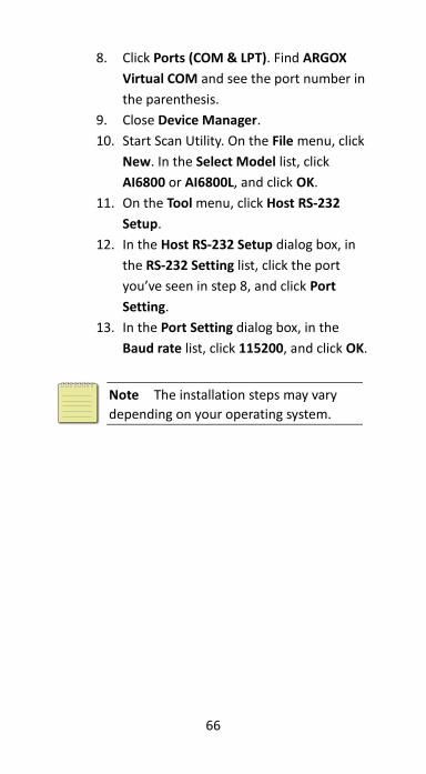
8. Click Ports (COM & LPT). Find ARGOX
Virtual COM and see the port number in
the parenthesis.
9. Close Device Manager.
10. Start Scan Utility. On the File menu, click
New. In the Select Model list, click
AI6800 or AI6800L, and click OK.
11. On the Tool menu, click Host RS-232
Setup.
12. In the Host RS-232 Setup dialog box, in
the RS-232 Setting list, click the port
you’ve seen in step 8, and click Port
Setting.
13. In the Port Setting dialog box, in the
Baud rate list, click 115200, and click OK.
Note The installation steps may vary
depending on your operating system.
67
4 Bar codes
Each bar code has different attributes for you
to change as you need.
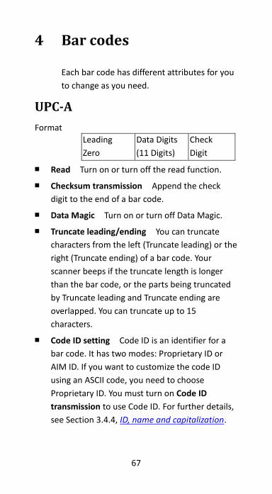
UPC-A
Format
Leading
Zero
Data Digits
(11 Digits)
Check
Digit
■ Read Turn on or turn off the read function.
■ Checksum transmission Append the check
digit to the end of a bar code.
■ Data Magic Turn on or turn off Data Magic.
■ Truncate leading/ending You can truncate
characters from the left (Truncate leading) or the
right (Truncate ending) of a bar code. Your
scanner beeps if the truncate length is longer
than the bar code, or the parts being truncated
by Truncate leading and Truncate ending are
overlapped. You can truncate up to 15
characters.
■ Code ID setting Code ID is an identifier for a
bar code. It has two modes: Proprietary ID or
AIM ID. If you want to customize the code ID
using an ASCII code, you need to choose
Proprietary ID. You must turn on Code ID
transmission to use Code ID. For further details,
see Section 3.4.4, ID, name and capitalization.
68
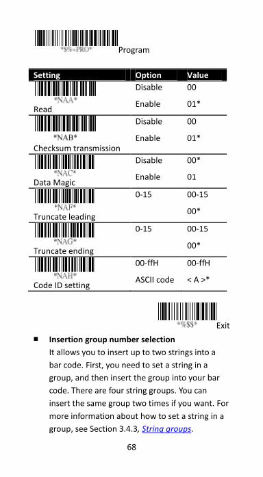
Program
Setting Option Value
Read
Disable
Enable
00
01*
Checksum transmission
Disable
Enable
00
01*
Data Magic
Disable
Enable
00*
01
Truncate leading
0-15 00-15
00*
Truncate ending
0-15 00-15
00*
Code ID setting
00-ffH
ASCII code
00-ffH
< A >*
Exit
■ Insertion group number selection
It allows you to insert up to two strings into a
bar code. First, you need to set a string in a
group, and then insert the group into your bar
code. There are four string groups. You can
insert the same group two times if you want. For
more information about how to set a string in a
group, see Section 3.4.3, String groups.
69
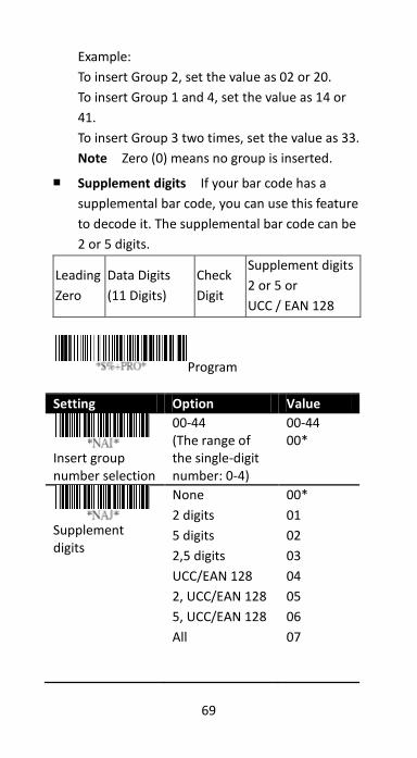
Example:
To insert Group 2, set the value as 02 or 20.
To insert Group 1 and 4, set the value as 14 or
41.
To insert Group 3 two times, set the value as 33.
Note Zero (0) means no group is inserted.
■ Supplement digits If your bar code has a
supplemental bar code, you can use this feature
to decode it. The supplemental bar code can be
2 or 5 digits.
Leading
Zero
Data Digits
(11 Digits)
Check
Digit
Supplement digits
2 or 5 or
UCC / EAN 128
Program
Setting Option Value
Insert group number selection
00-44 (The range of the single-digit number: 0-4)
00-44 00*
Supplement digits
None
2 digits
5 digits
2,5 digits
UCC/EAN 128
2, UCC/EAN 128
5, UCC/EAN 128
All
00*
01
02
03
04
05
06
07
70
Exit
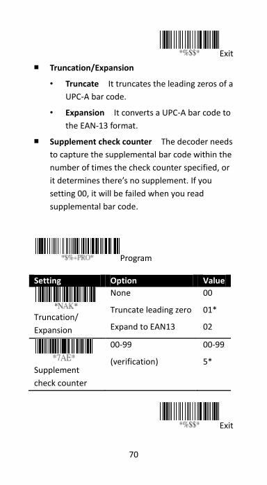
■ Truncation/Expansion
• Truncate It truncates the leading zeros of a
UPC-A bar code.
• Expansion It converts a UPC-A bar code to
the EAN-13 format.
■ Supplement check counter The decoder needs
to capture the supplemental bar code within the
number of times the check counter specified, or
it determines there’s no supplement. If you
setting 00, it will be failed when you read
supplemental bar code.
Program Setting Option Value
Truncation/
Expansion
None
Truncate leading zero
Expand to EAN13
00
01*
02
Supplement
check counter
00-99
(verification)
00-99
5*
Exit The
71
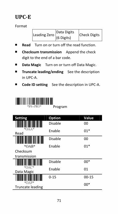
UPC-E
Format
Leading Zero Data Digits
(6 Digits) Check Digits
■ Read Turn on or turn off the read function.
■ Checksum transmission Append the check
digit to the end of a bar code.
■ Data Magic Turn on or turn off Data Magic.
■ Truncate leading/ending See the description
in UPC-A.
■ Code ID setting See the description in UPC-A.
Program
Setting Option Value
Read
Disable
Enable
00
01*
Checksum transmission
Disable
Enable
00
01*
Data Magic
Disable
Enable
00*
01
Truncate leading
0-15 00-15
00*
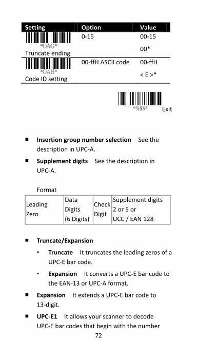
72
Setting Option Value
Truncate ending
0-15 00-15
00*
Code ID setting
00-ffH ASCII code 00-ffH
< E >*
Exit
■ Insertion group number selection See the
description in UPC-A.
■ Supplement digits See the description in
UPC-A.
Format
Leading
Zero
Data
Digits
(6 Digits)
Check
Digit
Supplement digits
2 or 5 or
UCC / EAN 128
■ Truncate/Expansion
• Truncate It truncates the leading zeros of a
UPC-E bar code.
• Expansion It converts a UPC-E bar code to
the EAN-13 or UPC-A format.
■ Expansion It extends a UPC-E bar code to
13-digit.
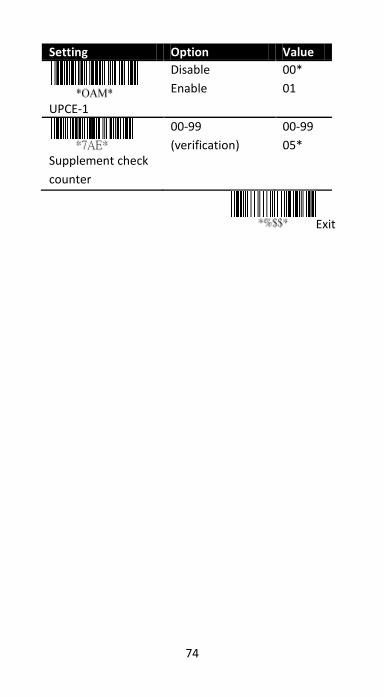
■ UPC-E1 It allows your scanner to decode
UPC-E bar codes that begin with the number
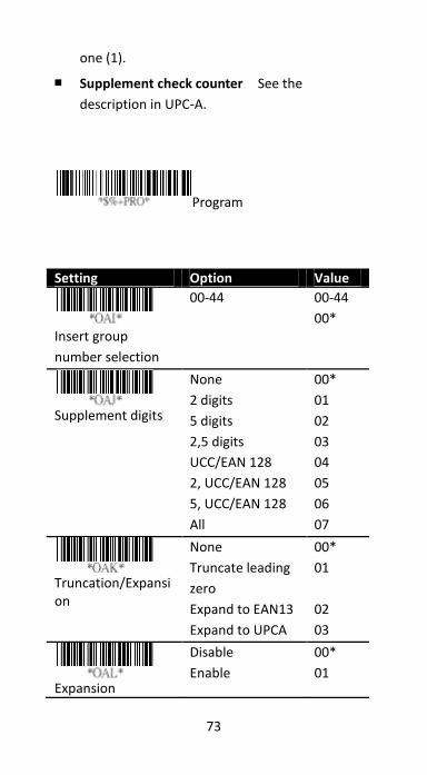
73
one (1).
■ Supplement check counter See the
description in UPC-A.
Program
Setting Option Value
Insert group
number selection
00-44 00-44
00*
Supplement digits
None
2 digits
5 digits
2,5 digits
UCC/EAN 128
2, UCC/EAN 128
5, UCC/EAN 128
All
00*
01
02
03
04
05
06
07
Truncation/Expansion
None
Truncate leading
zero
Expand to EAN13
Expand to UPCA
00*
01
02
03
Expansion
Disable
Enable
00*
01
74
Setting Option Value
UPCE-1
Disable
Enable
00*
01
Supplement check
counter
00-99
(verification)
00-99
05*
Exit
75
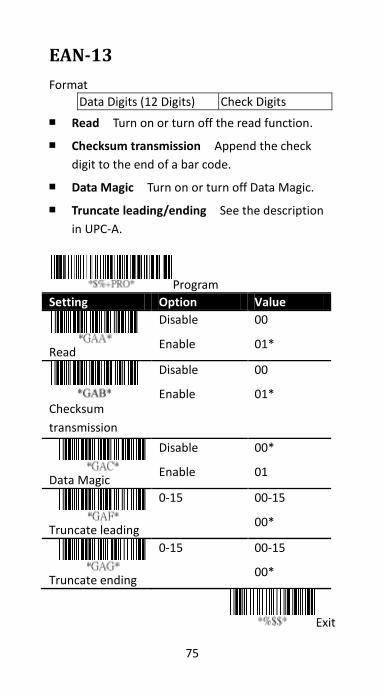
EAN-13
Format
Data Digits (12 Digits) Check Digits
■ Read Turn on or turn off the read function.
■ Checksum transmission Append the check
digit to the end of a bar code.
■ Data Magic Turn on or turn off Data Magic.
■ Truncate leading/ending See the description
in UPC-A.
Program
Setting Option Value
Read
Disable
Enable
00
01*
Checksum
transmission
Disable
Enable
00
01*
Data Magic
Disable
Enable
00*
01
Truncate leading
0-15 00-15
00*
Truncate ending
0-15 00-15
00*
Exit
76
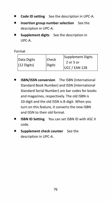
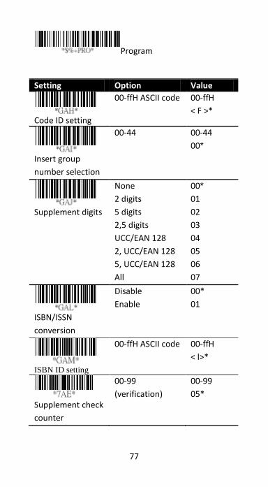
■ Code ID setting See the description in UPC-A.
■ Insertion group number selection See the
description in UPC-A.
■ Supplement digits See the description in
UPC-A.
Format
Data Digits
(12 Digits)
Check
Digits
Supplement Digits
2 or 5 or
UCC / EAN 128
■ ISBN/ISSN conversion The ISBN (International
Standard Book Number) and ISSN (International
Standard Serial Number) are bar codes for books
and magazines, respectively. The old ISBN is
10-digit and the old ISSN is 8-digit. When you
turn on this feature, it converts the new ISBN
and ISSN to their old format.
■ ISBN ID Setting You can set ISBN ID with ASC II
code.
■ Supplement check counter See the
description in UPC-A.
77
Program
Setting Option Value
Code ID setting
00-ffH ASCII code 00-ffH
< F >*
Insert group
number selection
00-44 00-44
00*
Supplement digits
None
2 digits
5 digits
2,5 digits
UCC/EAN 128
2, UCC/EAN 128
5, UCC/EAN 128
All
00*
01
02
03
04
05
06
07
ISBN/ISSN
conversion
Disable
Enable
00*
01
ISBN ID setting
00-ffH ASCII code 00-ffH
< l>*
Supplement check
counter
00-99
(verification)
00-99
05*

78
Exit
79
EAN-8
Format
Data Digits (7 Digits) Check Digits
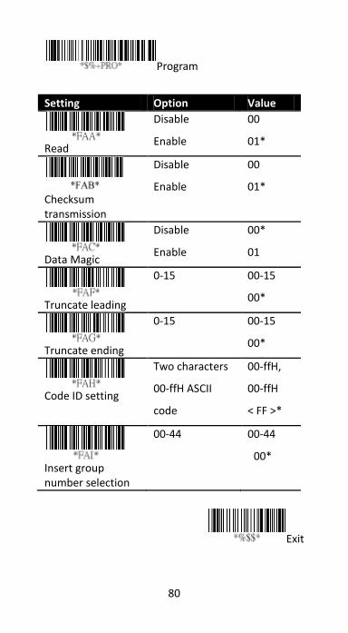
■ Read Turn on or turn off the read function.
■ Checksum transmission Append the check
digit to the end of a bar code.
■ Data Magic Turn on or turn off Data Magic.
■ Truncate leading/ending See the description
in UPC-A.
■ Code ID setting See the description in UPC-A.
■ Insertion group number selection See the
description in UPC-A.
80
Program
Setting Option Value
Read
Disable
Enable
00
01*
Checksum transmission
Disable
Enable
00
01*
Data Magic
Disable
Enable
00*
01
Truncate leading
0-15 00-15
00*
Truncate ending
0-15 00-15
00*
Code ID setting
Two characters
00-ffH ASCII
code
00-ffH,
00-ffH
< FF >*
Insert group number selection
00-44 00-44
00*
Exit
81
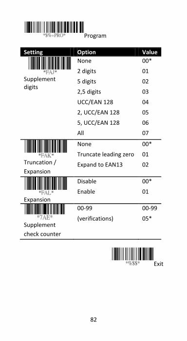
■ Supplement digits See the description in
UPC-A.
Format
Data
Digits
(7 Digits)
Check
Digits
Supplement Digits
2 or 5 or
UCC/EAN 128
■ Truncate/Expansion
• Truncate It truncates the leading zeros of
an EAN-8 bar code.
• Expansion It converts an EAN-8 bar code
to the EAN-13 format.
■ Expansion It extends an EAN-8 bar code to
13-digit.
■ Supplement check counter See the
description in UPC-A.
82
Program
Setting Option Value
Supplement digits
None
2 digits
5 digits
2,5 digits
UCC/EAN 128
2, UCC/EAN 128
5, UCC/EAN 128
All
00*
01
02
03
04
05
06
07
Truncation /
Expansion
None
Truncate leading zero
Expand to EAN13
00*
01
02
Expansion
Disable
Enable
00*
01
Supplement
check counter
00-99
(verifications)
00-99
05*
Exit
83
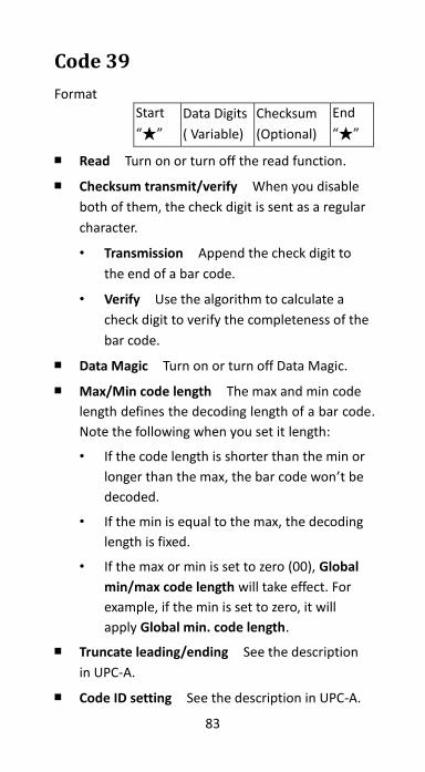
Code 39
Format
Start
“★”
Data Digits
( Variable)
Checksum
(Optional)
End
“★”
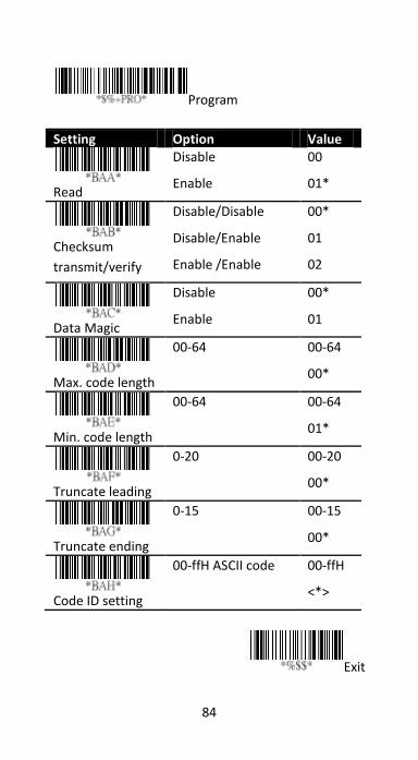
■ Read Turn on or turn off the read function.
■ Checksum transmit/verify When you disable
both of them, the check digit is sent as a regular
character.
• Transmission Append the check digit to
the end of a bar code.
• Verify Use the algorithm to calculate a
check digit to verify the completeness of the
bar code.
■ Data Magic Turn on or turn off Data Magic.
■ Max/Min code length The max and min code
length defines the decoding length of a bar code.
Note the following when you set it length:
• If the code length is shorter than the min or
longer than the max, the bar code won’t be
decoded.
• If the min is equal to the max, the decoding
length is fixed.
• If the max or min is set to zero (00), Global
min/max code length will take effect. For
example, if the min is set to zero, it will
apply Global min. code length.
■ Truncate leading/ending See the description
in UPC-A.
■ Code ID setting See the description in UPC-A.
84
Program
Setting Option Value
Read
Disable
Enable
00
01*
Checksum
transmit/verify
Disable/Disable
Disable/Enable
Enable /Enable
00*
01
02
Data Magic
Disable
Enable
00*
01
Max. code length
00-64 00-64
00*
Min. code length
00-64 00-64
01*
Truncate leading
0-20 00-20
00*
Truncate ending
0-15 00-15
00*
Code ID setting
00-ffH ASCII code 00-ffH
<*>
Exit
85
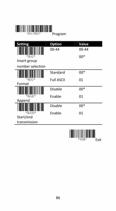
■ Insertion group number selection See the
description in UPC-A.
■ Format It converts the ASCII codes in the Code
39 bar code to regular characters.
■ Append It decodes and concatenates several
Code 39 bar codes that have a space character
at their beginning. Your scanner stops
concatenating and sends all concatenated data
to your computer when it decodes a Code 39 bar
code that doesn’t have a space character at its
beginning, or when it decodes a bar code that is
not Code 39.
If your scanner decodes a bar code that has a
space character at its beginning, it won’t send its
Code ID, Preamble and Prefix; if it decodes a bar
code that doesn’t have a space character, it
won’t send its Code ID and Prefix.
■ Start/End transmission
It sends the start and the stop codes of a bar
code to your computer.
86
Program
Setting Option Value
Insert group
number selection
00-44 00-44
00*
Format
Standard
Full ASCII
00*
01
Append
Disable
Enable
00*
01
Start/end transmission
Disable
Enable
00*
01
Exit
87
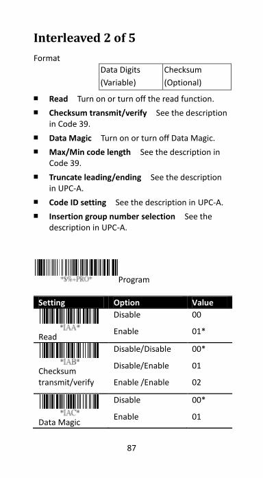
Interleaved 2 of 5
Format
Data Digits
(Variable)
Checksum
(Optional)
■ Read Turn on or turn off the read function.
■ Checksum transmit/verify See the description in Code 39.
■ Data Magic Turn on or turn off Data Magic.
■ Max/Min code length See the description in Code 39.
■ Truncate leading/ending See the description in UPC-A.
■ Code ID setting See the description in UPC-A.
■ Insertion group number selection See the description in UPC-A.
Program
Setting Option Value
Read
Disable
Enable
00
01*
Checksum transmit/verify
Disable/Disable
Disable/Enable
Enable /Enable
00*
01
02
Data Magic
Disable
Enable
00*
01

88
Setting Option Value
Max. code leading
00-64 00-64
00*
Min. code leading
00-64 00-64
00*
Truncate leading
0-15 00-15
00*
Truncate ending
0-15 00-15
00*
Code ID setting
00-ffH ASCII code 00-ffH
< i >*
Insert group number selection
00-44 00-44
00*
Exit
89
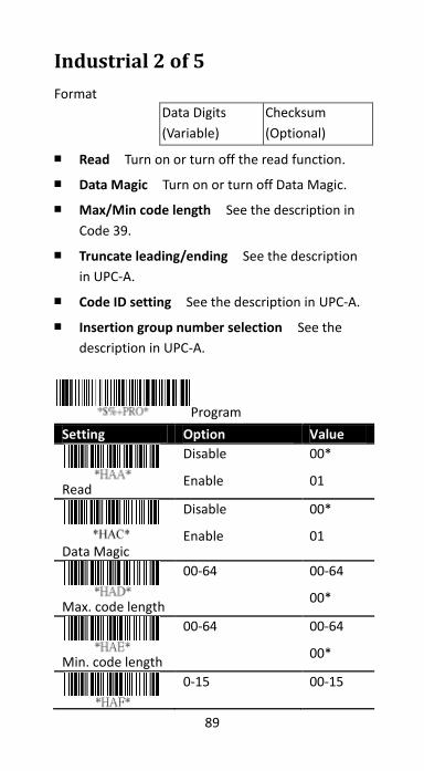
Industrial 2 of 5
Format
Data Digits
(Variable)
Checksum
(Optional)
■ Read Turn on or turn off the read function.
■ Data Magic Turn on or turn off Data Magic.
■ Max/Min code length See the description in
Code 39.
■ Truncate leading/ending See the description
in UPC-A.
■ Code ID setting See the description in UPC-A.
■ Insertion group number selection See the
description in UPC-A.
Program
Setting Option Value
Read
Disable
Enable
00*
01
Data Magic
Disable
Enable
00*
01
Max. code length
00-64 00-64
00*
Min. code length
00-64 00-64
00*
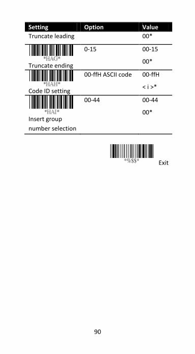
0-15 00-15
90
Exit
Setting Option Value
Truncate leading 00*
Truncate ending
0-15 00-15
00*
Code ID setting
00-ffH ASCII code 00-ffH
< i >*
Insert group
number selection
00-44 00-44
00*
91
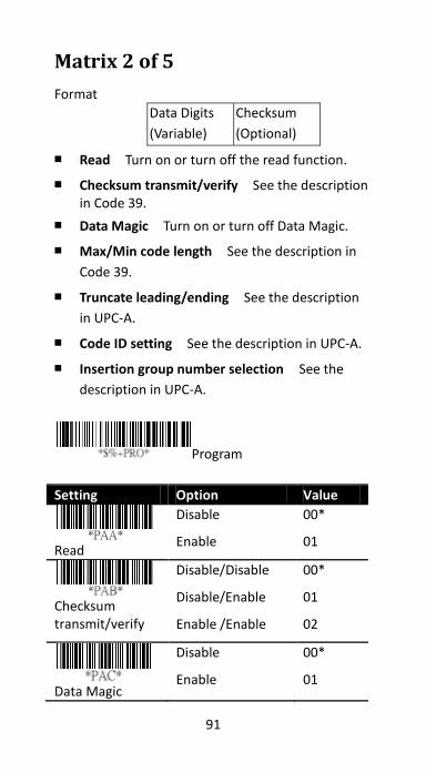
Matrix 2 of 5
Format
Data Digits
(Variable)
Checksum
(Optional)
■ Read Turn on or turn off the read function.
■ Checksum transmit/verify See the description in Code 39.
■ Data Magic Turn on or turn off Data Magic.
■ Max/Min code length See the description in
Code 39.
■ Truncate leading/ending See the description
in UPC-A.
■ Code ID setting See the description in UPC-A.
■ Insertion group number selection See the
description in UPC-A.
Program Setting Option Value
Read
Disable
Enable
00*
01
Checksum transmit/verify
Disable/Disable
Disable/Enable
Enable /Enable
00*
01
02
Data Magic
Disable
Enable
00*
01
92
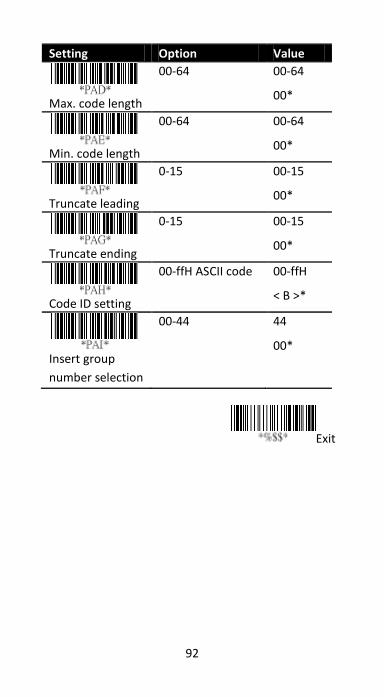
Setting Option Value
Max. code length
00-64 00-64
00*
Min. code length
00-64 00-64
00*
Truncate leading
0-15 00-15
00*
Truncate ending
0-15 00-15
00*
Code ID setting
00-ffH ASCII code 00-ffH
< B >*
Insert group
number selection
00-44 44
00*
Exit
93
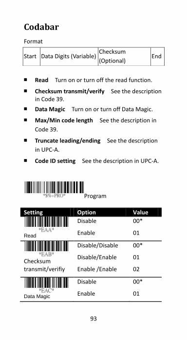
Codabar
Format
■ Read Turn on or turn off the read function.
■ Checksum transmit/verify See the description in Code 39.
■ Data Magic Turn on or turn off Data Magic.
■ Max/Min code length See the description in
Code 39.
■ Truncate leading/ending See the description
in UPC-A.
■ Code ID setting See the description in UPC-A.
Program
Setting Option Value
Read
Disable
Enable
00*
01
Checksum transmit/verifiy
Disable/Disable
Disable/Enable
Enable /Enable
00*
01
02
Data Magic
Disable
Enable
00*
01
Start Data Digits (Variable) Checksum
(Optional) End
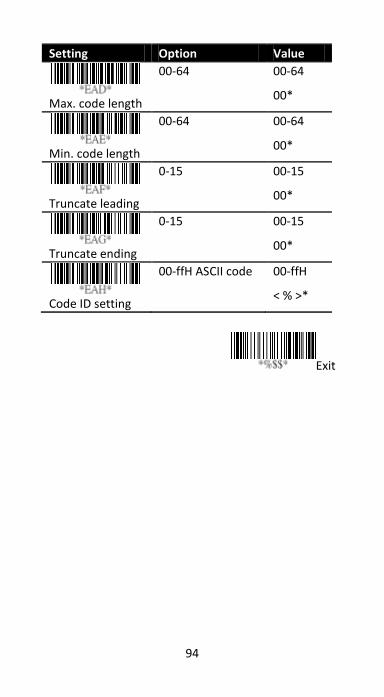
94
Setting Option Value
Max. code length
00-64 00-64
00*
Min. code length
00-64 00-64
00*
Truncate leading
0-15 00-15
00*
Truncate ending
0-15 00-15
00*
Code ID setting
00-ffH ASCII code 00-ffH
< % >*
Exit
95
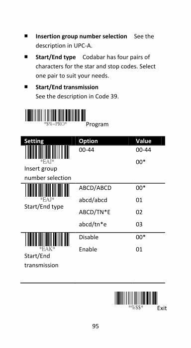
■ Insertion group number selection See the
description in UPC-A.
■ Start/End type Codabar has four pairs of
characters for the star and stop codes. Select
one pair to suit your needs.
■ Start/End transmission
See the description in Code 39.
Program
Setting Option Value
Insert group
number selection
00-44 00-44
00*
Start/End type
ABCD/ABCD
abcd/abcd
ABCD/TN*E
abcd/tn*e
00*
01
02
03
Start/End
transmission
Disable
Enable
00*
01
Exit
96
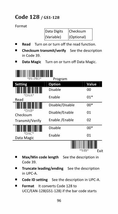
Code 128 / GS1-128
Format
Data Digits
(Variable)
Checksum
(Optional)
■ Read Turn on or turn off the read function.
■ Checksum transmit/verify See the description in Code 39.
■ Data Magic Turn on or turn off Data Magic.
Program
Setting Option Value
Read
Disable
Enable
00
01*
Checksum
Transmit/Verify
Disable/Disable
Disable/Enable
Enable /Enable
00*
01
02
Data Magic
Disable
Enable
00*
01
Exit
■ Max/Min code length See the description in Code 39.
■ Truncate leading/ending See the description in UPC-A.
■ Code ID setting See the description in UPC-A.
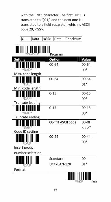
■ Format It converts Code 128 to UCC/EAN-128(GS1-128) if the bar code starts
97
with the FNC1 character. The first FNC1 is translated to “]C1,” and the next one is translated to a field separator, which is ASCII code 29, <GS>.
]C1 Data <GS> Data Checksum
Program
Setting Option Value
Max. code length
00-64 00-64
00*
Min. code length
00-64 00-64
01*
Truncate leading
0-15 00-15
00*
Truncate ending
0-15 00-15
00*
Code ID setting
00-ffH ASCII code 00-ffH
< # >*
Insert group
number selection
00-44 00-44
00*
Format
Standard
UCC/EAN-128
00
01*
Exit
98
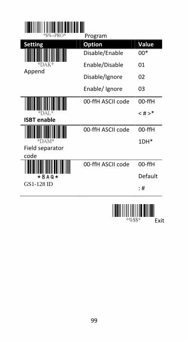
■ Append It decodes and concatenates several
Code 128 bar codes that have the FNC2
character at their beginning. Your scanner stops
concatenating and sends all concatenated data
to your computer when it decodes a bar code
that doesn’t have an FNC2 character at its
beginning, or when it decodes a bar code that is
not Code 128.
■ ISBT enable Enable or disable ISBN barcode
readable.
■ Field separator code It is used for the bar
codes converted to UCC/EAN 128 only. You can
use the ASCII code to customize your field
separator. The default separator is <GS>.
■ GS1-128 ID See the description in UPC-A.
99
Program
Setting Option Value
Append
Disable/Enable
Enable/Disable
Disable/Ignore
Enable/ Ignore
00*
01
02
03
ISBT enable
00-ffH ASCII code 00-ffH
< # >*
Field separator code
00-ffH ASCII code 00-ffH
1DH*
GS1-128 ID
00-ffH ASCII code 00-ffH
Default
: #
Exit
100
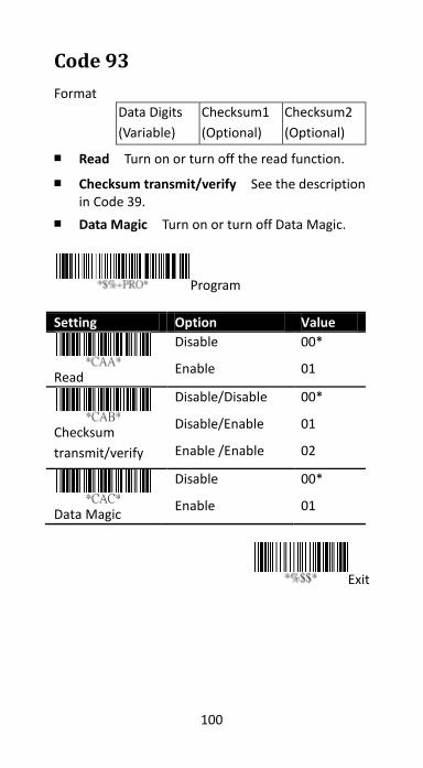
Code 93
Format
Data Digits
(Variable)
Checksum1
(Optional)
Checksum2
(Optional)
■ Read Turn on or turn off the read function.
■ Checksum transmit/verify See the description in Code 39.
■ Data Magic Turn on or turn off Data Magic.
Program
Setting Option Value
Read
Disable
Enable
00*
01
Checksum
transmit/verify
Disable/Disable
Disable/Enable
Enable /Enable
00*
01
02
Data Magic
Disable
Enable
00*
01
Exit
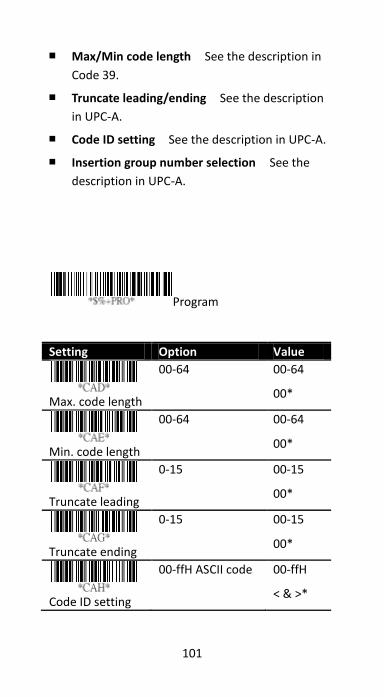
101
■ Max/Min code length See the description in
Code 39.
■ Truncate leading/ending See the description
in UPC-A.
■ Code ID setting See the description in UPC-A.
■ Insertion group number selection See the
description in UPC-A.
Program
Setting Option Value
Max. code length
00-64 00-64
00*
Min. code length
00-64 00-64
00*
Truncate leading
0-15 00-15
00*
Truncate ending
0-15 00-15
00*
Code ID setting
00-ffH ASCII code 00-ffH
< & >*

102
Setting Option Value
Insert group
number selection
00-44 00-44
00*
Exit
103
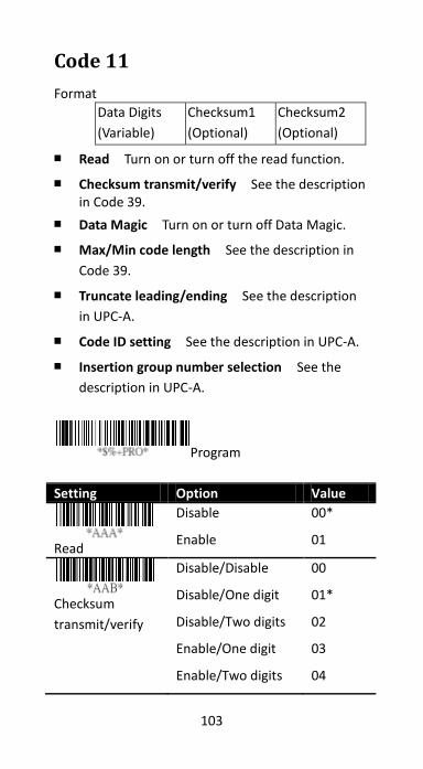
Code 11
Format
Data Digits
(Variable)
Checksum1
(Optional)
Checksum2
(Optional)
■ Read Turn on or turn off the read function.
■ Checksum transmit/verify See the description in Code 39.
■ Data Magic Turn on or turn off Data Magic.
■ Max/Min code length See the description in
Code 39.
■ Truncate leading/ending See the description
in UPC-A.
■ Code ID setting See the description in UPC-A.
■ Insertion group number selection See the
description in UPC-A.
Program
Setting Option Value
Read
Disable
Enable
00*
01
Checksum
transmit/verify
Disable/Disable
Disable/One digit
Disable/Two digits
Enable/One digit
Enable/Two digits
00
01*
02
03
04
104
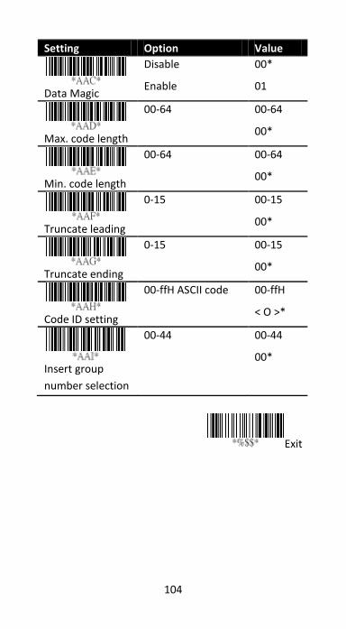
Setting Option Value
Data Magic
Disable
Enable
00*
01
Max. code length
00-64 00-64
00*
Min. code length
00-64 00-64
00*
Truncate leading
0-15 00-15
00*
Truncate ending
0-15 00-15
00*
Code ID setting
00-ffH ASCII code 00-ffH
< O >*
Insert group
number selection
00-44 00-44
00*
Exit
105
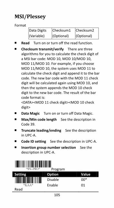
MSI/Plessey
Format
Data Digits
(Variable)
Checksum1
(Optional)
Checksum2
(Optional)
■ Read Turn on or turn off the read function.
■ Checksum transmit/verify There are three algorithms for you to calculate the check digit of a MSI bar code: MOD 10, MOD 10/MOD 10, MOD 11/MOD 10. For example, if you choose MOD 11/MOD 10, the system uses MOD 11 to calculate the check digit and append it to the bar code. The new bar code with the MOD 11 check digit will be calculated again using MOD 10, and then the system appends the MOD 10 check digit to the new bar code. The result of the bar code format is: <DATA><MOD 11 check digit><MOD 10 check digit>
■ Data Magic Turn on or turn off Data Magic.
■ Max/Min code length See the description in Code 39.
■ Truncate leading/ending See the description in UPC-A.
■ Code ID setting See the description in UPC-A.
■ Insertion group number selection See the description in UPC-A.
Program
Setting Option Value
Read
Disable
Enable
00*
01
106
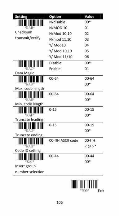
Setting Option Value
Checksum
transmit/verify
N/disable
N/MOD 10
N/Mod 10,10
N/mod 11,10
Y/ Mod10
Y/ Mod 10,10
Y/ Mod 11/10
00*
01
02
03
04
05
06
Data Magic
Disable
Enable
00*
01
Max. code length
00-64 00-64
00*
Min. code length
00-64 00-64
00*
Truncate leading
0-15 00-15
00*
Truncate ending
0-15 00-15
00*
Code ID setting
00-ffH ASCII code 00-ffH
< @ >*
Insert group
number selection
00-44 00-44
00*
Exit
107
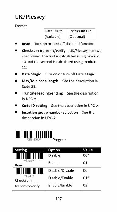
UK/Plessey
Format
Data Digits
(Variable)
Checksum1+2
(Optional)
■ Read Turn on or turn off the read function.
■ Checksum transmit/verify UK/Plessey has two
checksums. The first is calculated using modulo
10 and the second is calculated using modulo
11.
■ Data Magic Turn on or turn off Data Magic.
■ Max/Min code length See the description in
Code 39.
■ Truncate leading/ending See the description
in UPC-A.
■ Code ID setting See the description in UPC-A.
■ Insertion group number selection See the
description in UPC-A.
Program
Setting Option Value
Read
Disable
Enable
00*
01
Checksum
transmit/verify
Disable/Disable
Disable/Enable
Enable/Enable
00
01*
02
108
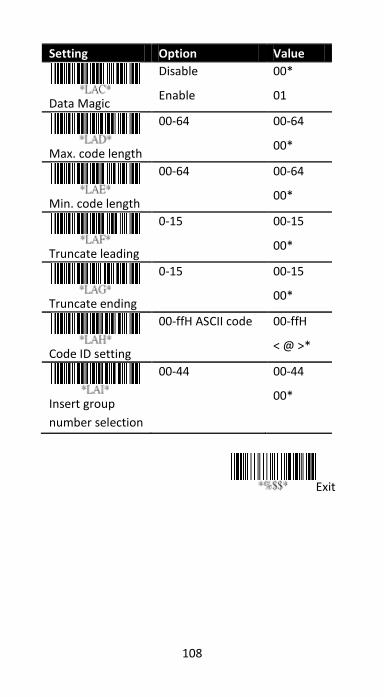
Setting Option Value
Data Magic
Disable
Enable
00*
01
Max. code length
00-64 00-64
00*
Min. code length
00-64 00-64
00*
Truncate leading
0-15 00-15
00*
Truncate ending
0-15 00-15
00*
Code ID setting
00-ffH ASCII code 00-ffH
< @ >*
Insert group
number selection
00-44 00-44
00*
Exit
109
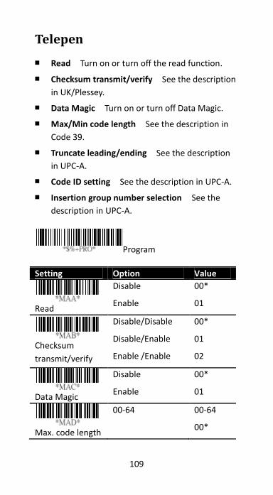
Telepen
■ Read Turn on or turn off the read function.
■ Checksum transmit/verify See the description
in UK/Plessey.
■ Data Magic Turn on or turn off Data Magic.
■ Max/Min code length See the description in
Code 39.
■ Truncate leading/ending See the description
in UPC-A.
■ Code ID setting See the description in UPC-A.
■ Insertion group number selection See the
description in UPC-A.
Program
Setting Option Value
Read
Disable
Enable
00*
01
Checksum
transmit/verify
Disable/Disable
Disable/Enable
Enable /Enable
00*
01
02
Data Magic
Disable
Enable
00*
01
Max. code length
00-64 00-64
00*
110
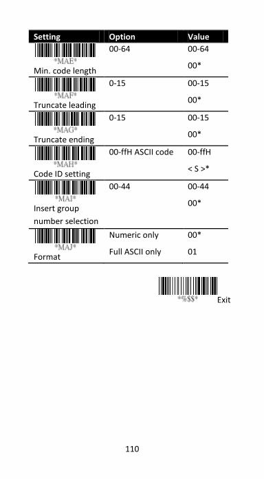
Setting Option Value
Min. code length
00-64 00-64
00*
Truncate leading
0-15 00-15
00*
Truncate ending
0-15 00-15
00*
Code ID setting
00-ffH ASCII code 00-ffH
< S >*
Insert group
number selection
00-44 00-44
00*
Format
Numeric only
Full ASCII only
00*
01
Exit
111
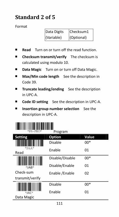
Standard 2 of 5
Format
Data Digits
(Variable)
Checksum1
(Optional)
■ Read Turn on or turn off the read function.
■ Checksum transmit/verify The checksum is
calculated using modulo 10.
■ Data Magic Turn on or turn off Data Magic.
■ Max/Min code length See the description in
Code 39.
■ Truncate leading/ending See the description
in UPC-A.
■ Code ID setting See the description in UPC-A.
■ Insertion group number selection See the
description in UPC-A.
Program
Setting Option Value
Read
Disable
Enable
00*
01
Check-sum
transmit/verify
Disable/Disable
Disable/Enable
Enable /Enable
00*
01
02
Data Magic
Disable
Enable
00*
01
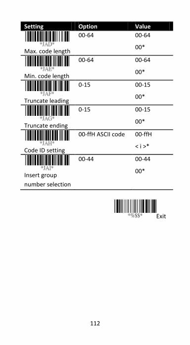
112
Setting Option Value
Max. code length
00-64 00-64
00*
Min. code length
00-64 00-64
00*
Truncate leading
0-15 00-15
00*
Truncate ending
0-15 00-15
00*
Code ID setting
00-ffH ASCII code 00-ffH
< i >*
Insert group
number selection
00-44 00-44
00*
Exit
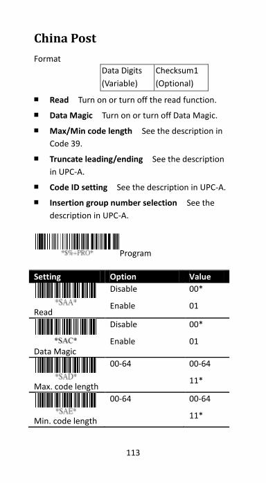
113
China Post
Format
Data Digits
(Variable)
Checksum1
(Optional)
■ Read Turn on or turn off the read function.
■ Data Magic Turn on or turn off Data Magic.
■ Max/Min code length See the description in
Code 39.
■ Truncate leading/ending See the description
in UPC-A.
■ Code ID setting See the description in UPC-A.
■ Insertion group number selection See the
description in UPC-A.
Program
Setting Option Value
Read
Disable
Enable
00*
01
Data Magic
Disable
Enable
00*
01
Max. code length
00-64 00-64
11*
Min. code length
00-64 00-64
11*
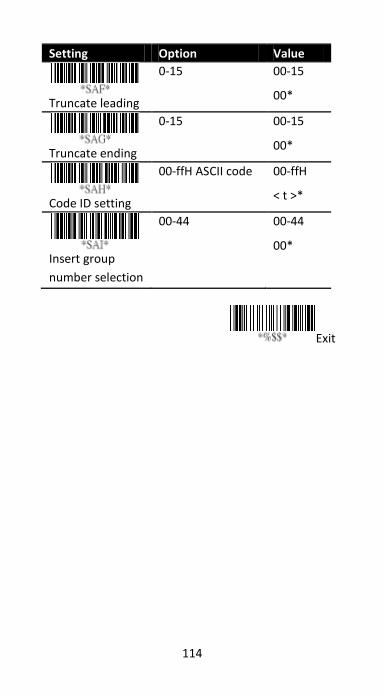
114
Setting Option Value
Truncate leading
0-15 00-15
00*
Truncate ending
0-15 00-15
00*
Code ID setting
00-ffH ASCII code 00-ffH
< t >*
Insert group
number selection
00-44 00-44
00*
Exit

115
Italian Pharmacode (Code 32)
Format
Data Digits
(Variable)
Checksum1
(Optional)
■ Read Turn on or turn off the read function.
■ Data Magic Turn on or turn off Data Magic.
■ Max/Min code length See the description in
Code 39.
■ Truncate leading/ending See the description
in UPC-A.
■ Code ID setting See the description in UPC-A.
■ Insertion group number selection See the
description in UPC-A.
■ Leading “A” Add the character “A” at the
beginning of a Code 32 bar code.
Program
Setting Option Value
Read
Disable
Enable
00*
01
Data Magic
Disable
Enable
00*
01
Max. code length
00-64 00-64
12*
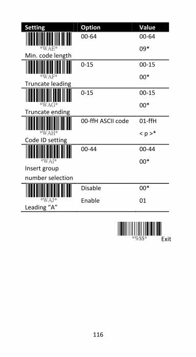
116
Setting Option Value
Min. code length
00-64 00-64
09*
Truncate leading
0-15 00-15
00*
Truncate ending
0-15 00-15
00*
Code ID setting
00-ffH ASCII code 01-ffH
< p >*
Insert group
number selection
00-44 00-44
00*
Leading “A”
Disable
Enable
00*
01
Exit

117
Code 16K
■ Read Turn on or turn off the read function.
■ Data Magic Turn on or turn off Data Magic.
■ Truncate leading/ending See the description
in UPC-A.
■ Code ID setting See the description in UPC-A.
■ Insertion group number selection See the
description in UPC-A.
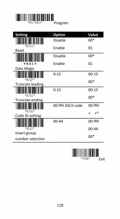
118
Program
Setting Option Value
Read
Disable
Enable
00*
01
Data Magic
Disable
Enable
00*
01
Truncate leading
0-15 00-15
00*
Truncate ending
0-15 00-15
00*
Code ID setting
00-ffH ASCII code 00-ffH
< >*
Insert group
number selection
00-44 00-ffH
00-44
00*
Exit
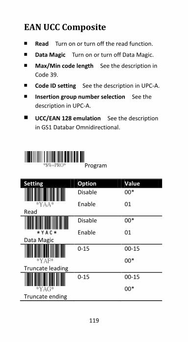
119
EAN UCC Composite
■ Read Turn on or turn off the read function.
■ Data Magic Turn on or turn off Data Magic.
■ Max/Min code length See the description in
Code 39.
■ Code ID setting See the description in UPC-A.
■ Insertion group number selection See the
description in UPC-A.
■ UCC/EAN 128 emulation See the description
in GS1 Databar Omnidirectional.
Program
Setting Option Value
Read
Disable
Enable
00*
01
Data Magic
Disable
Enable
00*
01
Truncate leading
0-15 00-15
00*
Truncate ending
0-15 00-15
00*
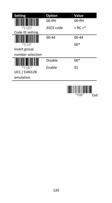
120
Setting Option Value
Code ID setting
00-ffH
ASCII code
00-ffH
< RC >*
Insert group
number selection
00-44 00-44
00*
UCC / EAN128
emulation
Disable
Enable
00*
01
Exit
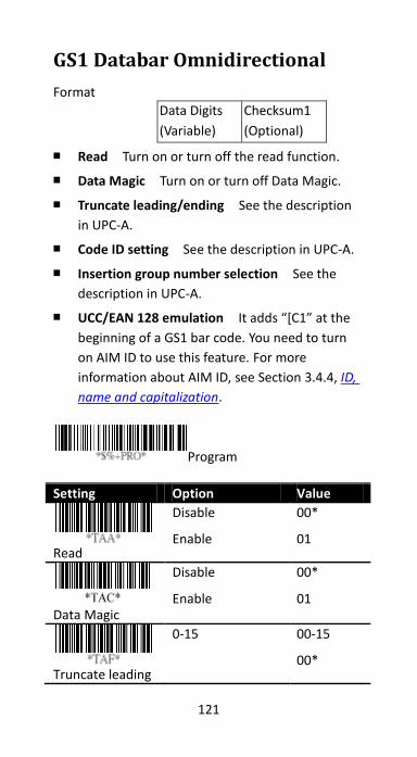
121
GS1 Databar Omnidirectional
Format
Data Digits
(Variable)
Checksum1
(Optional)
■ Read Turn on or turn off the read function.
■ Data Magic Turn on or turn off Data Magic.
■ Truncate leading/ending See the description
in UPC-A.
■ Code ID setting See the description in UPC-A.
■ Insertion group number selection See the
description in UPC-A.
■ UCC/EAN 128 emulation It adds “[C1” at the
beginning of a GS1 bar code. You need to turn
on AIM ID to use this feature. For more
information about AIM ID, see Section 3.4.4, ID,
name and capitalization.
Program
Setting Option Value
Read
Disable
Enable
00*
01
Data Magic
Disable
Enable
00*
01
Truncate leading
0-15 00-15
00*
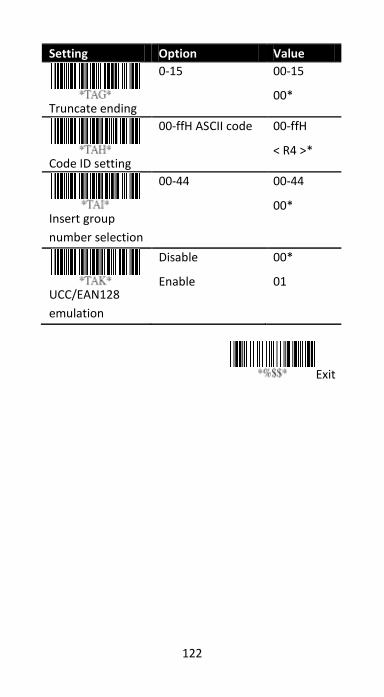
122
Setting Option Value
Truncate ending
0-15 00-15
00*
Code ID setting
00-ffH ASCII code 00-ffH
< R4 >*
Insert group
number selection
00-44 00-44
00*
UCC/EAN128
emulation
Disable
Enable
00*
01
Exit
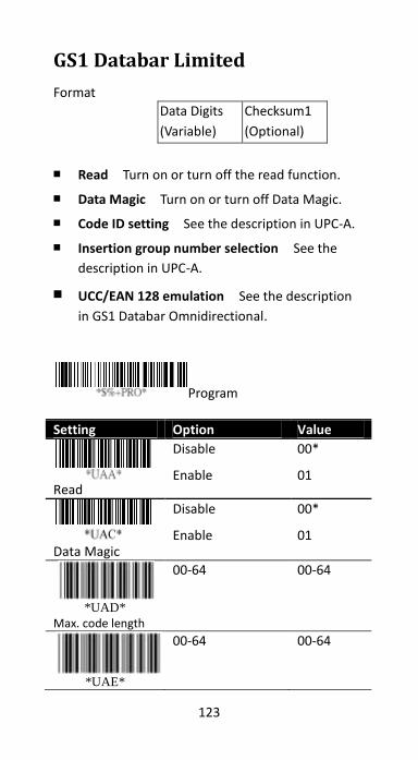
123
GS1 Databar Limited
Format
Data Digits
(Variable)
Checksum1
(Optional)
■ Read Turn on or turn off the read function.
■ Data Magic Turn on or turn off Data Magic.
■ Code ID setting See the description in UPC-A.
■ Insertion group number selection See the
description in UPC-A.
■ UCC/EAN 128 emulation See the description
in GS1 Databar Omnidirectional.
Program
Setting Option Value
Read
Disable
Enable
00*
01
Data Magic
Disable
Enable
00*
01
*UAD*
Max. code length
00-64 00-64
*UAE*
00-64 00-64
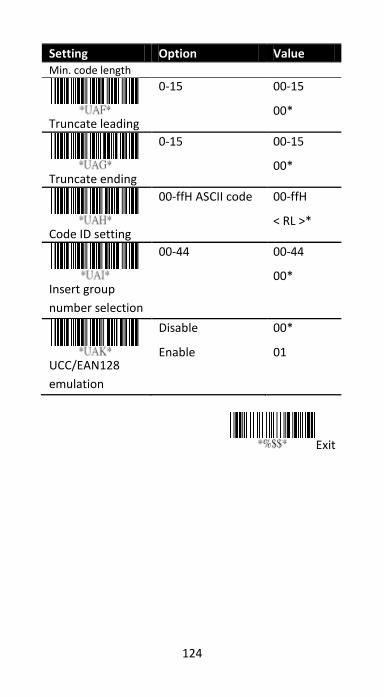
124
Setting Option Value Min. code length
Truncate leading
0-15 00-15
00*
Truncate ending
0-15 00-15
00*
Code ID setting
00-ffH ASCII code 00-ffH
< RL >*
Insert group
number selection
00-44 00-44
00*
UCC/EAN128
emulation
Disable
Enable
00*
01
Exit
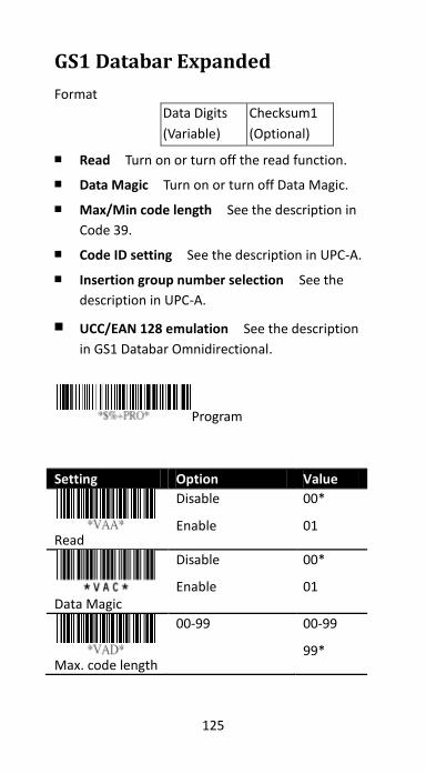
125
GS1 Databar Expanded
Format
Data Digits
(Variable)
Checksum1
(Optional)
■ Read Turn on or turn off the read function.
■ Data Magic Turn on or turn off Data Magic.
■ Max/Min code length See the description in
Code 39.
■ Code ID setting See the description in UPC-A.
■ Insertion group number selection See the
description in UPC-A.
■ UCC/EAN 128 emulation See the description
in GS1 Databar Omnidirectional.
Program
Setting Option Value
Read
Disable
Enable
00*
01
Data Magic
Disable
Enable
00*
01
Max. code length
00-99 00-99
99*
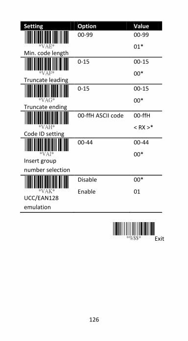
126
Setting Option Value
Min. code length
00-99 00-99
01*
Truncate leading
0-15 00-15
00*
Truncate ending
0-15 00-15
00*
Code ID setting
00-ffH ASCII code 00-ffH
< RX >*
Insert group
number selection
00-44 00-44
00*
UCC/EAN128
emulation
Disable
Enable
00*
01
Exit
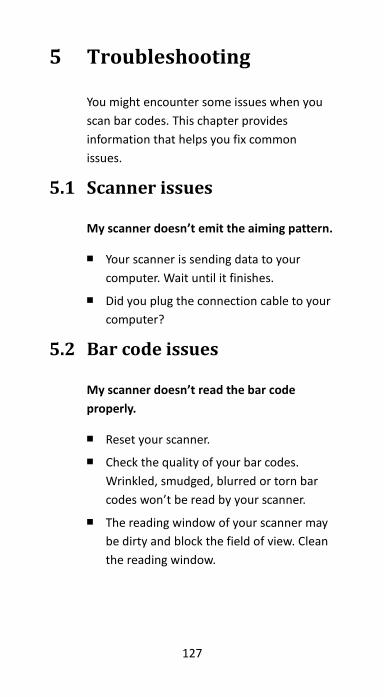
127
5 Troubleshooting
You might encounter some issues when you
scan bar codes. This chapter provides
information that helps you fix common
issues.
5.1 Scanner issues
My scanner doesn’t emit the aiming pattern.
■ Your scanner is sending data to your
computer. Wait until it finishes.
■ Did you plug the connection cable to your
computer?
5.2 Bar code issues
My scanner doesn’t read the bar code
properly.
■ Reset your scanner.
■ Check the quality of your bar codes.
Wrinkled, smudged, blurred or torn bar
codes won’t be read by your scanner.
■ The reading window of your scanner may
be dirty and block the field of view. Clean
the reading window.
128
The data isn’t sent to my computer.
■ Make sure the USB or RS-232 cable is
tightly plugged into your computer.
My scanner doesn’t decode the bar code,
but the bar code type is supported.
■ Did you turn on Read for the bar code
type?
■ The density of your bar code may be too
high for your scanner to decode.
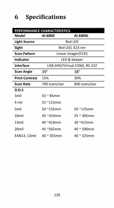
129
6 Specifications
PERFORMANCE CHARACTERISTICS Model AI-6800 AI-6800L
Light Source Red LED
Sight Red LED, 623 nm
Scan Pattern Linear Imager(CCD)
Indicator LED & beeper
Interface USB (HID/Virtual COM), RS-232
Scan Angle 39° 38°
Print Contrast 15% 30%
Scan Rate 700 scans/sec 600 scans/sec
D.O.F.
3mil 55 ~ 85mm
4 mil 55 ~115mm
5mil 50 ~135mm 50 ~125mm
10mil 35 ~310mm 25 ~ 305mm
13mil 40 ~410mm 30 ~415mm
20mil 45 ~565mm 40 ~ 590mm
EAN13, 13mil 40 ~ 355mm 40 ~ 325mm
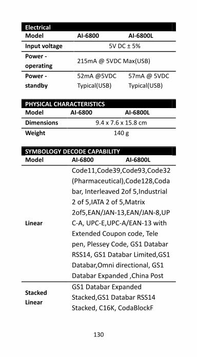
130
Electrical Model AI-6800 AI-6800L
Input voltage 5V DC ± 5%
Power -
operating 215mA @ 5VDC Max(USB)
Power -
standby
52mA @5VDC
Typical(USB)
57mA @ 5VDC
Typical(USB)
PHYSICAL CHARACTERISTICS Model AI-6800 AI-6800L
Dimensions 9.4 x 7.6 x 15.8 cm
Weight 140 g
SYMBOLOGY DECODE CAPABILITY Model AI-6800 AI-6800L
Linear
Code11,Code39,Code93,Code32
(Pharmaceutical),Code128,Coda
bar, Interleaved 2of 5,Industrial
2 of 5,IATA 2 of 5,Matrix
2of5,EAN/JAN‐13,EAN/JAN‐8,UP
C‐A, UPC‐E,UPC‐A/EAN‐13 with
Extended Coupon code, Tele
pen, Plessey Code, GS1 Databar
RSS14, GS1 Databar Limited,GS1
Databar,Omni directional, GS1
Databar Expanded ,China Post
Stacked
Linear
GS1 Databar Expanded
Stacked,GS1 Databar RSS14
Stacked, C16K, CodaBlockF
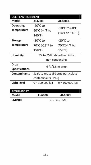
131
USER ENVIRONMENT Model AI-6800 AI-6800L
Operating
Temperature
-20°C to
60°C (-4°F to
140°F)
-10°C to 60°C
(14°F to 140°F)
Storage
Temperature
-30°C to
70°C (-22°F to
158°F)
-20°C to
70°C(-4°F to
158°F)
Humidity 5% to 95% related humidity,
non-condensing
Drop
Specifications 6 ft./1.8 m drop
Contaminants Seals to resist airborne particulate
contaminants (IP65)
Light level 0 ~ 100,000 lux 0 ~ 100,000 lux
REGULATORY Model AI-6800 AI-6800L
EMI/RFI CE, FCC, BSMI
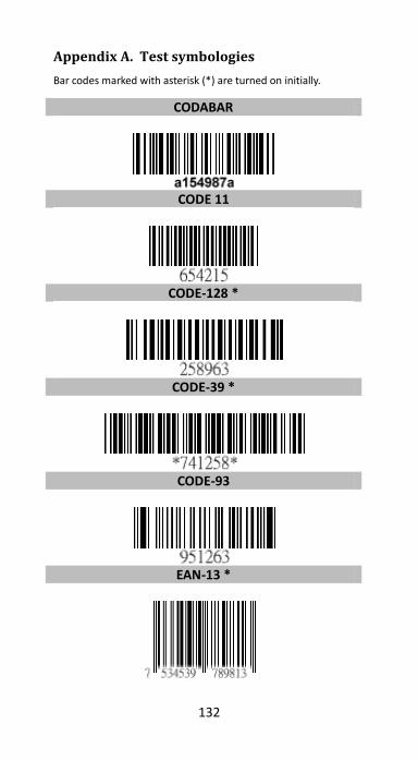
132
Appendix A. Test symbologies
Bar codes marked with asterisk (*) are turned on initially.
CODABAR
CODE 11
CODE-128 *
CODE-39 *
CODE-93
EAN-13 *
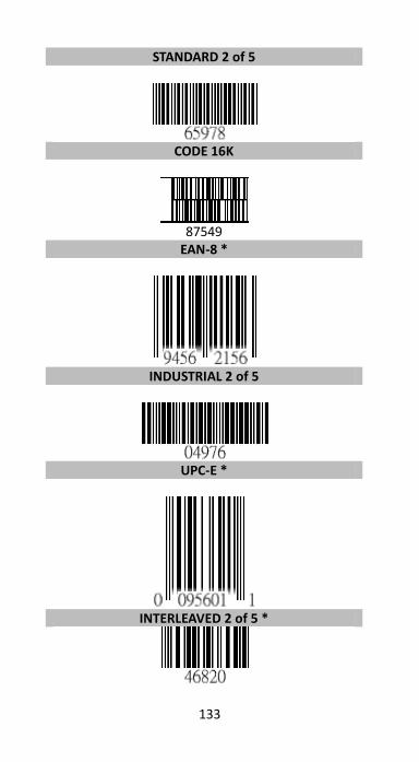
133
STANDARD 2 of 5
CODE 16K
87549
EAN-8 *
INDUSTRIAL 2 of 5
UPC-E *
INTERLEAVED 2 of 5 *
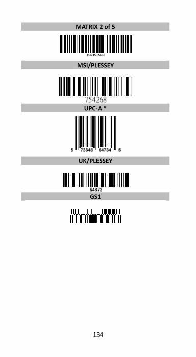
134
MATRIX 2 of 5
MSI/PLESSEY
UPC-A *
UK/PLESSEY
GS1
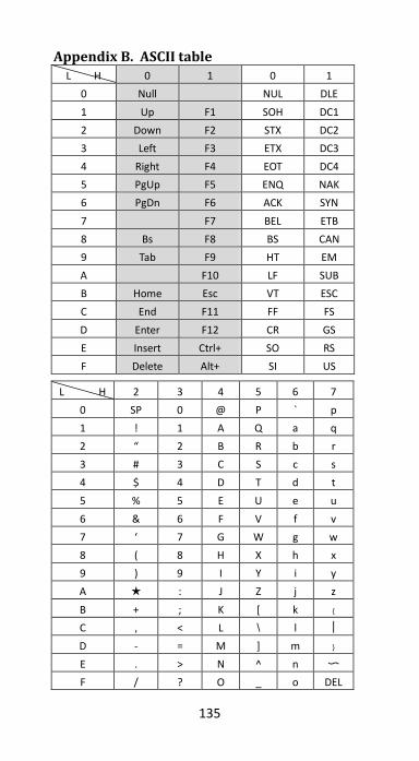
135
Appendix B. ASCII table L H 0 1 0 1
0 Null NUL DLE
1 Up F1 SOH DC1
2 Down F2 STX DC2
3 Left F3 ETX DC3
4 Right F4 EOT DC4
5 PgUp F5 ENQ NAK
6 PgDn F6 ACK SYN
7 F7 BEL ETB
8 Bs F8 BS CAN
9 Tab F9 HT EM
A F10 LF SUB
B Home Esc VT ESC
C End F11 FF FS
D Enter F12 CR GS
E Insert Ctrl+ SO RS
F Delete Alt+ SI US
L H 2 3 4 5 6 7
0 SP 0 @ P ` p
1 ! 1 A Q a q
2 “ 2 B R b r
3 # 3 C S c s
4 $ 4 D T d t
5 % 5 E U e u
6 & 6 F V f v
7 ‘ 7 G W g w
8 ( 8 H X h x
9 ) 9 I Y i y
A ★ : J Z j z
B + ; K [ k ﹛
C , < L \ l ︱
D - = M ] m ﹜
E . > N ^ n 〜
F / ? O _ o DEL
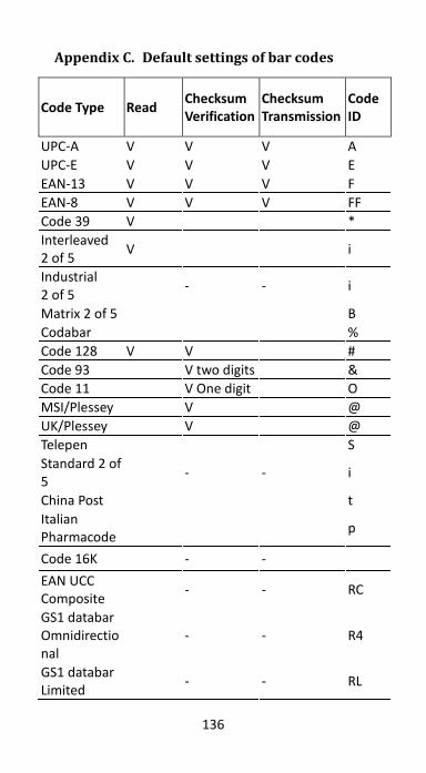
136
Appendix C. Default settings of bar codes
Code Type Read Checksum Verification
Checksum Transmission
Code ID
UPC-A V V V A
UPC-E V V V E
EAN-13 V V V F
EAN-8 V V V FF
Code 39 V *
Interleaved 2 of 5
V i
Industrial 2 of 5
- - i
Matrix 2 of 5 B
Codabar %
Code 128 V V #
Code 93 V two digits &
Code 11 V One digit O
MSI/Plessey V @
UK/Plessey V @
Telepen S
Standard 2 of 5
- - i
China Post t
Italian Pharmacode
p
Code 16K - -
EAN UCC Composite
- - RC
GS1 databar Omnidirectional
- - R4
GS1 databar Limited
- - RL
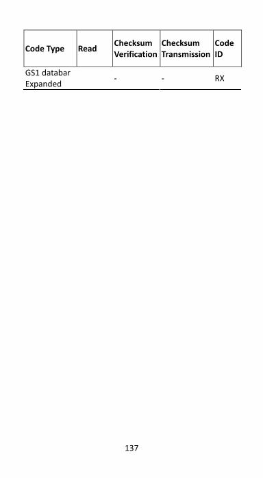
137
Code Type Read Checksum Verification
Checksum Transmission
Code ID
GS1 databar Expanded
- - RX
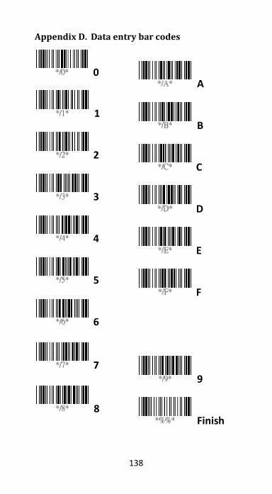
138
Appendix D. Data entry bar codes
0
A
1
B
2
C
3
D
4
E
5
F
6
7
9
8
Finish
Top Related