


Languages
Pages
Legal


M-Algorithm-Based Optimal Detectors for Spatial
Modulation
Zengshan Tian, Zhe Li, Mu Zhou, and Xiaobo Yang Chongqing Key Lab of Mobile Communications Technology,
Chongqing University of Posts and Telecommunications, Chongqing 400065, China
Email: {tianzs, zhoumu}@cqupt.edu.cn; {s_lizhe, s_yangxiaobo}@qq.com
Abstract—A novel M-algorithm-based detector, namely M-
algorithm to maximum-likelihood (M-ML), for spatial
modulation (SM) receiver is proposed recently, however, due to
the miscalculation of metrics, bit-error-rate (BER) performance
of M-ML is far away from optimal actually. In this paper, a
modified M-ML detector, which calculates accumulated metrics
of each layer and can achieve optimal BER performance, is
proposed; Furthermore, an M-algorithm-based constellation-
reduction (MCR) method specially for SM in high correlated
environment is proposed, MCR is capable of combining with
maximum-likelihood (ML) and M-ML to further reduce
complexity. The BER performance of M–ML and MCR is
simulated, simulation results show that the proposed detectors
can achieve almost the same BER performance to ML detector
while reducing the computational complexity significantly. Index Terms—Spatial modulation, M-algorithm, correlated
channel, maximum-likelihood
I. INTRODUCTION
To meet the requirement of the development of future
mobile communications, the work on wireless
communication systems strives for the purpose of high
data transfer rate [1]. Although multiple-input multiple-
output (MIMO) technique is widely recognized as an
important approach to increase data transfer rate, MIMO
systems could be incapable of action in the aspects of
energy efficiency and detection complexity in the high
data rate condition [2]. To solve this problem, spatial
modulation (SM) which is known as a single radio-
frequency MIMO technique, is proposed in [3]-[5].
Compared with conventional MIMO systems, SM makes
use of the difference of MIMO channels to convey
information based on a new spatial dimension, thus the
conventional two-dimensional (2D) constellation is
extended to three-dimensional (3D) constellation as
shown in Fig. 1. Due to the high energy efficiency and
low detection complexity, SM is regarded as a candidate
technique for future wireless communication systems,
especially for large-scale MIMO [6].
Manuscript received January 8, 2015; revised April 15, 2015. Corresponding author email: [email protected].
doi:10.12720/jcm.10.4.245-251
Im
Re
Im
Re
Im
Re
Antenna 1
Antenna 2
Antenna 4
Im
Antenna 3
Re
(0 0)
(0 1)
(1 0)
(1 1)
(0 0 0 0)(0 0 0 1)
(0 0 1 0)
(0 1 0 0)(0 1 0 1)
(1 0 0 0)(1 0 0 1)
(1 1 0 0)(1 1 0 1)
(0 1 1 0)
(1 0 1 0)
(1 1 1 0)(1 1 1 1) Fig. 1. SM 3D constellation (4 transmit antennas and QPSK)
SM is also an effective technique to overcome inter-
channel interference (ICI) and time synchronization
among antennas which are necessary for MIMO systems
[3]-[5]. Besides, the complexity of optimal detector for
SM has a exponential relationship with modulation order
and increases linearly with the number of transmit and
receive antennas, thus SM can reduce detection
complexity significantly compared to conventional
MIMO [3]-[5]. However, since some transmit antennas
remain inactive in every channel use, SM offers a lower
throughput than spatial multiplexing [7]. This implies that
SM requires more transmit antennas or higher modulation
order for achieving the same spectral efficiency. As a
result, the complexity of SM with high data rate is still
great.
At the receiver, the optimal detection algorithm needs
to estimate both the modulated symbol and index of
selected antenna by a joint exhaustive search for
recovering the information data [8]. The most obvious
and efficient way to reduce complexity is to restrict
maximum-likelihood (ML) search space. For example,
the sphere decoder (SD) algorithm, applied to both
MIMO and SM [9]-[13], avoids the exhaustive search by
examining only those points that lie inside a sphere with
an appropriate radius.
However, another popular detector for MIMO systems,
M-algorithm to maximum-likelihood (M-ML) detector
[14], has barely been studied for SM to date. It can reduce
the complexity of ML detection by combining with QR
decomposition and tree search structure [15], [16]. The
main purpose of M-algorithm is that limit the candidate
constellation points to a fixed number M to reduce the
exhaustive search space. In [17], a novel M-algorithm-
Journal of Communications Vol. 10, No. 4, April 2015
©2015 Journal of Communications 245

based detection method called M-ML applied to spatial
modulation was proposed, the proposed algorithm has
fixed complexity and reduces complexity by using
parallel structure to limit the search space of optimum
decoder. However, follow the procedures described in
[17], the M-ML detector performs far away from the
optimal detector actually. This is mainly because the
metrics of each layer are miscalculated. In this paper, a
modified M-ML detector is proposed which corrects the
miscalculation of metrics and achieves optimal bit-error-
rate (BER) performance.
Considering the characteristics of SM, lower data rate
and complexity of detection, it is more suitable to be used
as an enhancement of uplink transmission [5]. Therefore,
in order to obtain higher data rate of uplink, the terminal
side needs to allocate a large number of transmit antennas.
However, due to the constraint of terminal size, it is
difficult to make the correlation coefficients of the
antennas to be low enough. In this high correlated
condition, the optimization of signal detection algorithm
is barely been studied.
Therefore, to reduce the complexity of SM signal
detection in high correlated channel, a novel M-
algorithm-based constellation-reduction algorithm called
MCR is proposed in this paper. MCR algorithm reduces
the constellation search space of ML by using the highly
relevant characteristics of transmit antennas while
maintaining an optimum performance. Moreover, MCR
can be combined with both ML and M-ML to get further
complexity reduction.
The rest of this paper is structured as follows. Section
II presents a general description of SM system model.
The modified M-ML detector and proposed MCR
algorithm are discussed in Section III. Section IV shows
some simulation results. Finally, the paper is concluded
in Section V.
Fig. 2. SM System Model.
II. SYSTEM MODEL
SM system block scheme is presented in Fig. 2.
Assume a tr NN SM system with L-ary constellation
and complete channel state information at receiver, the
steps of SM can be described as follows:
Step 1: Segment the input bit stream into blocks with
the length of )(log2 LNt .
Step 2: Each block is mapped into both constellation
points and space dimension, where L2log bits select a
symbol s from the constellation set S and tN2log bits
select one antenna out of tN transmit antennas.
Step 3: Every symbol is transmitted by the
correspondingly selected antenna, and the other antennas
stay idle during the same time slot.
Step 4: The receiver does signal detection in order to
estimate both the transmit symbol and the index of
selected antenna.
For example, assume a system with 4 transmit
antennas and BPSK constellation in Fig. 3. The
information bits are firstly segmented into blocks with 3
bits length, then mapped to a 1 BPSK symbol and
transmitted on one of the four available antennas.
Bit Stream
…00111110101001101010100110...
Spatial Modulation
Constellation
selection
Antenna
slection
-1 +1
BPSK
antenna 1
antenna 2
antenna 3
antenna 4
00
01
10
11
1(BPSK) antenna 4
Transmission
0 11
Fig. 3. SM with 4 transmit antennas and BPSK
The system model can be formulated as
nHXy , (1)
where y is the Nr-dim received symbol vector. H is the
tr NN channel matrix. X is the Nt-dim transmit symbol
vector modulated by L-QAM. n denotes the Nr-dim
Additive White Gaussian Noise (AWGN) with zero-mean
and variance σ2. Furthermore, based on the characteristics
of SM, the system model can be simplified into
nhnhy sx iii , (2)
where hi is the i-th column of H and denotes the complex
channel gain between the active transmit antenna and the
receive antennas. xi is the i-th element in X and can be
further written as the selected symbol s from the
constellation set S. tNi 1 , Ss .
At the receiver, the optimal detection algorithm is ML
detector in [8] and can be described as follows,
}{minarg
}{minarg
minarg],[
1,
1
2
,,
2
,
r
r
N
j
jsi
N
j
ijjsi
Fisi
MLML
E
shy
ssi hy
(3)
ChannelH
block segment
Signal
mapper
Bit stream
SM
mapper
Spatial Modulation
Bit stream
1
Nr
1
Nt
...
... Detector
Journal of Communications Vol. 10, No. 4, April 2015
©2015 Journal of Communications 246

where MLi and MLs are the estimations of i and s. i
denotes the transmit antenna index. s is the transmit
symbol, and F
represents Frobenius norm operation.
Use 2
, shyE ijjj to denote the metric of the j-th
receive antenna and i-th transmit antenna. Besides,
define1
k
k jjA E
to denote the accumulated metrics of
the k-th receive antenna.
1-st layer
2-nd layer
3-rd layer
1 2 3 4
Index of
transmit antenna
Fig. 4. Tree search structure of 4 3 SM system with BPSK
Similar to conventional MIMO system, ML detector of
SM system also has tree search structure. However, the
difference is that since only one antenna is active during
each transmission in SM, there is no need to do QR
decomposition to realize layer search. SM regards each
receive antenna as a level of the tree structure. Fig. 4
shows the tree search structure of a 34 SM system with
BPSK constellation, the black nodes represent the path
with smallest accumulated metrics.
The number of the real multiplications required by one
detector is calculated to examine the computational
complexity. The computational complexity of (3) is
LNNC tr
NN
MLtr 8
(4)
Computing 2
, shy ijj requires 8 real multiplications.
Equation (4) shows that the complexity of SM used
massive antennas or high-order modulation is still great.
In this paper, the extraordinarily popular Kronecker
channel model in [18], [19] is used as a general model to
deal with the correlated channels.
Define the transmitter and receiver correlation matrices
are tNR and
rNR
r
t
N
H
NTr
E
R
HHR (5)
t
r
N
H
NTr
E
R
HHR (6)
where E and Tr denote the expectation and trace
operator, H is the conjugate (Hermitian) transpose of a
matrix. Moreover, the spatial stationarity is assumed, i.e.,
the correlation coefficients remain invariant as long as the
antenna separations remain constant.
In order to simplify the description and simulation,
tk andrk represent the correlation coefficient of transmit
and receive antennas, respectively. Besides, assume that
the correlation coefficient between each antenna is
restricted to be the same real value, and 10 tk ,
10 rk . For example, the transmitter correlation
matrix of a four transmit antennas system can be written
as
1
1
1
1
ttt
ttt
ttt
ttt
kkk
kkk
kkk
kkk
Note that this restriction has no effect on the
simulation results and performance of the proposed
algorithm.
III. DETECTORS
In this section, the M-ML algorithm is modified and
the proposed detector specially for applying in high
correlated channel is described.
As shown in Fig. 4, ML detector of SM system also
has tree search structure, thus the M-algorithm can be
applied to SM. However, In [17], the expression of the
M-ML procedures has a mistake. The authors forgot to
calculate the sum value of the metrics where the metrics
of each layer should be accumulated metrics. The M-ML
algorithm can be modified in Table. I,
TABLE I: MODIFIED M-ML ALGORITHM
Initialization:
}],,...,2,1[|),{(0 SsNisiQ t ,
],,...,,...,[ 11 rr NNj MMMM M ,
1rNM , jj MM 1
Algorithm :
1: for rNj :1
2: for 1, ji s Q ( )
3: ( , )j ji s A
4: end
5: ( , )
arg( ( , ))j j ji s
Q M smallest i s
6: end
7: rNMLML Qsi ],[
where 2
,1
j
j k k ikA y h s
denotes the accumulated
metrics of the j-th receive antenna.
The number of multiplications required by M-ML is
given in [17]. The complexity of M-ML is
1
1
88
r
tr
N
i
itNN
MLM MLNC (7)
Journal of Communications Vol. 10, No. 4, April 2015
©2015 Journal of Communications 247
An important observation from (7) is that M-ML
algorithm has the advantage of variable complexity
depending on the controllable value of M, and associated
with the parallel structure, M–ML is a promising way to
application.
In this paper, the M-algorithm is also tailored to SM in
high correlated environment. However, different from the
joint estimation of transmit symbol and antenna index in
ML, the proposed MCR, which exploits the high
correlation between channels, reduces the search space
for constellations above all , and then conduct a joint
detection. The proposed MCR algorithm can be described
in Table. II,
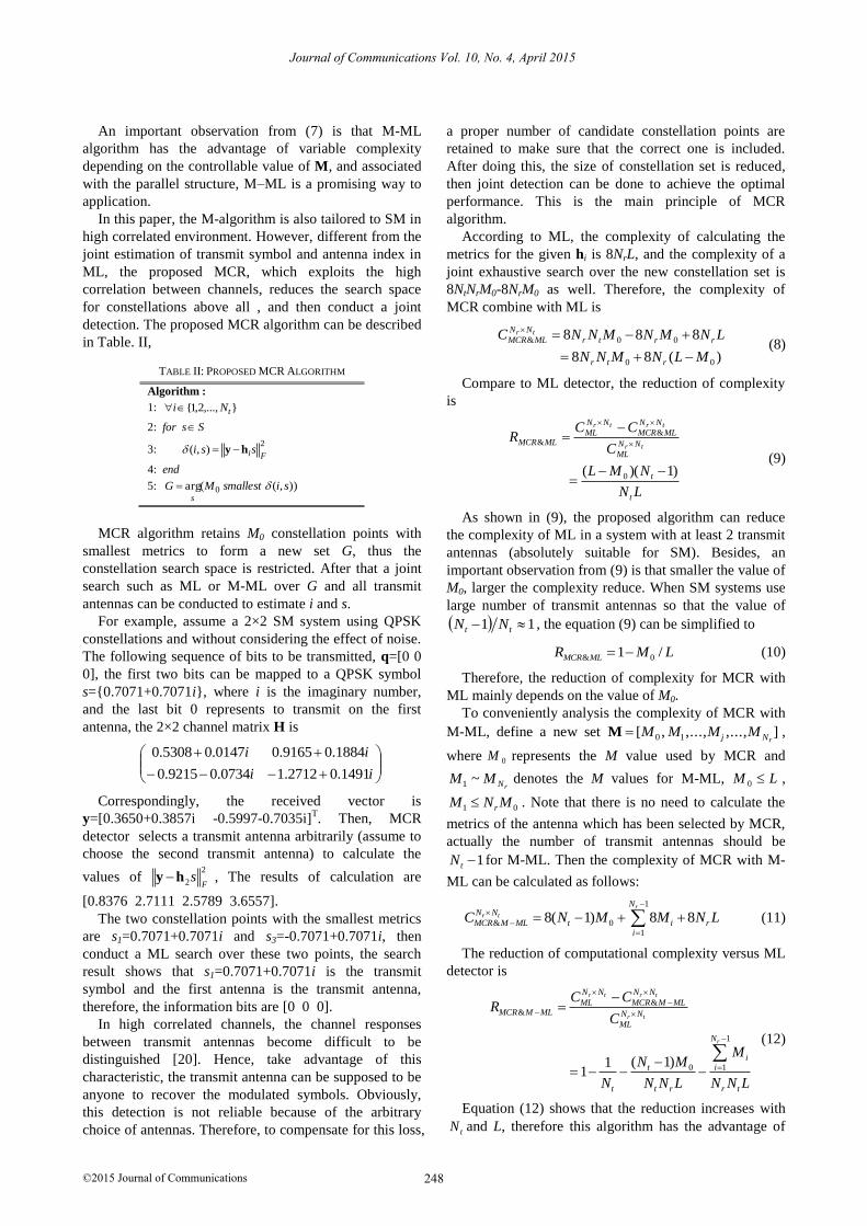
TABLE II: PROPOSED MCR ALGORITHM
Algorithm :
1: },...,2,1{ tNi
2: for s S
3: 2
),(Fissi hy
4: end
5: )),((arg 0 sismallestMGs
MCR algorithm retains M0 constellation points with
smallest metrics to form a new set G, thus the
constellation search space is restricted. After that a joint
search such as ML or M-ML over G and all transmit
antennas can be conducted to estimate i and s.
For example, assume a 2×2 SM system using QPSK
constellations and without considering the effect of noise.
The following sequence of bits to be transmitted, q=[0 0
0], the first two bits can be mapped to a QPSK symbol
s={0.7071+0.7071i}, where i is the imaginary number,
and the last bit 0 represents to transmit on the first
antenna, the 2×2 channel matrix H is
ii
ii
1491.02712.10734.09215.0
1884.09165.00147.05308.0
Correspondingly, the received vector is
y=[0.3650+0.3857i -0.5997-0.7035i]T. Then, MCR
detector selects a transmit antenna arbitrarily (assume to
choose the second transmit antenna) to calculate the
values of 2
2 Fshy , The results of calculation are
[0.8376 2.7111 2.5789 3.6557].
The two constellation points with the smallest metrics
are s1=0.7071+0.7071i and s3=-0.7071+0.7071i, then
conduct a ML search over these two points, the search
result shows that s1=0.7071+0.7071i is the transmit
symbol and the first antenna is the transmit antenna,
therefore, the information bits are [0 0 0].
In high correlated channels, the channel responses
between transmit antennas become difficult to be
distinguished [20]. Hence, take advantage of this
characteristic, the transmit antenna can be supposed to be
anyone to recover the modulated symbols. Obviously,
this detection is not reliable because of the arbitrary
choice of antennas. Therefore, to compensate for this loss,
a proper number of candidate constellation points are
retained to make sure that the correct one is included.
After doing this, the size of constellation set is reduced,
then joint detection can be done to achieve the optimal
performance. This is the main principle of MCR
algorithm.
According to ML, the complexity of calculating the
metrics for the given hi is 8NrL, and the complexity of a
joint exhaustive search over the new constellation set is
8NtNrM0-8NrM0 as well. Therefore, the complexity of
MCR combine with ML is
)(88
888
00
00&
MLNMNN
LNMNMNNC
rtr
rrtr
NN
MLMCRtr
(8)
Compare to ML detector, the reduction of complexity
is
LN
NML
C
CCR
t
t
NN
ML
NN
MLMCR
NN
MLMLMCR
tr
trtr
)1)(( 0
&&
(9)
As shown in (9), the proposed algorithm can reduce
the complexity of ML in a system with at least 2 transmit
antennas (absolutely suitable for SM). Besides, an
important observation from (9) is that smaller the value of
M0, larger the complexity reduce. When SM systems use
large number of transmit antennas so that the value of
11 tt NN , the equation (9) can be simplified to
LMR MLMCR /1 0& (10)
Therefore, the reduction of complexity for MCR with
ML mainly depends on the value of M0.
To conveniently analysis the complexity of MCR with
M-ML, define a new set ],...,,...,,[ 10 rNj MMMMM ,
where 0M represents the M value used by MCR and
rNMM ~1 denotes the M values for M-ML, LM 0 ,
01 MNM r . Note that there is no need to calculate the
metrics of the antenna which has been selected by MCR,
actually the number of transmit antennas should be
1tN for M-ML. Then the complexity of MCR with M-
ML can be calculated as follows:
1
& 01
8( 1) 8 8r
r t
NN N
MCR M ML t i ri
C N M M N L
(11)
The reduction of computational complexity versus ML
detector is
&&
1
0 1( 1)11
r t r t
r t
r
N N N N
ML MCR M MLMCR M ML N N
ML
N
it i
t t r r t
C CR
C
MN M
N N N L N N L
(12)
Equation (12) shows that the reduction increases with
tN and L, therefore this algorithm has the advantage of
Journal of Communications Vol. 10, No. 4, April 2015
©2015 Journal of Communications 248

applying in large-scale antennas and high-order
modulation condition.
Thanks to the introduction of M-algorithm, the
algorithms above are all have fixed complexity and
parallel structure which are more suitable for practical
implementation.
Compare with other SM detectors, for instance, the
novel detection algorithm for SM based on the modified
sphere decoder (SM-SD) which has variable complexity
and serial detection structure and is difficult for practical
applications, the algorithms above with fixed complexity
and breadth-first parallel structure are all conducive to
practical implementation. However, they also have some
drawbacks, such as higher average complexity and
complicated metric sorting process, however, considering
the practical application, M-algorithm-based detectors are
still a promising way for SM signal detection.
IV. SIMULATION RESULTS
This section provides simulation results to compare
BER performance of the proposed algorithms and optimal
detector. In the simulations, a 4×4 uncoded SM system
with three different bit rates (r = 4, 6, 8 bpcu) is
considered, the Kronecker channel model is used to
realize correlated fading environment. Configuration of
the simulator can be found in Table. III,
TABLE III: CONFIGURATION OF THE SIMULATOR
Simulation software Channel model
Modulation type
Frame length Times of simulation loops
MATLAB Kronecker
QPSK,16QAM,64QAM
1000 At least 104
The BER performances versus signal-noise-ratio (SNR)
are shown in Fig. 5-7. Firstly, a comparison between M-
ML and modified M-ML is shown in Fig. 5, where
0.1t rk k . MCR with ML and MCR with modified
M-ML are compared with the optimal detector in Fig. 6
and Fig. 7, where 0.8tk and 0.1rk .
0 5 10 15 20 25
10-5
10-4
10-3
10-2
10-1
100
SNR(dB)
BE
R
ML(r=4)
ML(r=4)
ML(r=8)
M-ML(r=4)
M-ML(r=6)
M-ML(r=8)
Modified M-ML(r=4)
Modified M-ML(r=6)
Modified M-ML(r=8)
Fig. 5. BER performance for M-ML and modified M-ML versus ML.
In Fig. 5, the values of M for each rate are [12 6 4 1]r=4,
[32 10 4 1]r=6, [64 34 16 1]r=8, an obvious observation is
that with the same value of M the modified M-ML can
achieve almost optimal performance while M-ML
perform far away from it. The reason is obvious, due to
the miscalculation of metrics, M-ML cannot retain the
correct candidate points, consequently, the performance
decreases substantially. However, the modified M-ML,
which uses accumulated metrics to measure each
candidate point, can retain the correct points and near
optimal performance.
0 5 10 15 20 25 30
10-5
10-4
10-3
10-2
10-1
100
SNR(dB)
BE
R
ML(r=4)
ML(r=6)
ML(r=8)
MCR with ML(r=4)
MCR with ML(r=6)
MCR with ML(r=8)
Fig. 6. BER performance for MCR with ML versus ML.
0 5 10 15 20 25 30
10-5
10-4
10-3
10-2
10-1
100
SNR(dB)
BE
R
ML(r=4)
ML(r=6)
ML(r=8)
MCR with M-ML(r=4)
MCR with M-ML(r=6)
MCR with M-ML(r=8)
Fig. 7. BER performance for MCR with M-ML versus ML.
Fig. 6 and Fig. 7 demonstrates that MCR with ML or
MML can perform extremely close to ML, note that
MCR with M-ML has a performance loss comparable
with ML at low SNR, this is because of the characteristic
of M-ML [17], the values of M are not big enough to
contain the correct estimates when the power of noise has
a great influence on tree search. Moreover, for MCR with
ML, the corresponding values of M0 are 2, 8, 32 and the
reductions of complexity for each rate are all 37.5%; for
MCR with M-ML, the corresponding values of M for
each rate are [2 4 3 2 1]r=4 ,[8 12 6 4 1]r=6, [32 32 16 8
1]r=8 and the further reduction of complexity are 51.56%,
57.03%, 60.16%, respectively. As can be seen, a higher
reduction of complexity can be achieved for higher data
rates, this is mainly due to the fact that the complexity of
ML detection with high-order modulation increases more
significantly than with the M-ML detectors.
Journal of Communications Vol. 10, No. 4, April 2015
©2015 Journal of Communications 249
According to the simulation results, another significant
phenomenon is that the channel correlation has a great
negative influence on BER performance, specifically, the
larger the correlation coefficient is, the worse the system
performs. This is mainly due to the high correlated
channel responses of transmit antennas are difficult to be
distinguished so that the probability of estimating the
correct antenna index declines.
V. CONCLUSIONS
In this paper, the M-ML detector for SM is modified,
the modified one, which uses accumulated metrics to
measure each candidate point, can obtain optimal BER
performance; moreover, another M-algorithm-based
detector called MCR is proposed, which can restrict the
size of constellation space for joint exhaustive search in
correlated environment. More specifically, MCR takes
advantage of the correlation between transmit antennas to
reduce search space of modulated symbols and does a
joint search just over the retained points and all transmit
antennas. Furthermore, MCR detectors can be associated
with both ML and M-ML to achieve optimal BER
performance, as well as reduces the computational
complexity significantly when the value of M is
appropriately selected.
ACKNOWLEDGMENT
This work was supported in part by the Program for
Changjiang Scholars and Innovative Research Team in
University (IRT1299), National Natural Science
Foundation of China (61301126, 61471077), Special
Fund of Chongqing Key Laboratory (CSTC),
Fundamental and Frontier Research Project of Chongqing
(cstc2013jcyjA40041, cstc2013jcyjA40032,
cstc2013jcyjA40034), Scientific and Technological
Research Program of Chongqing Municipal Education
Commission (KJ130528, KJ1400413), Startup
Foundation for Doctors of CQUPT (A2012-33), Science
Foundation for Young Scientists of CQUPT (A2012-77,
A2013-31), and Student Research Training Program of
CQUPT (A2013-64).
REFERENCES
[1] J. G. Andrews, S. Buzzi, C. Wan, et al, “What Will 5G Be?” IEEE
J. Sel. Areas Commun., vol. 32, no. 6, pp. 1065-1082, Jun. 2014.
[2] F. Rusek, D. Persson, B. K. Lau, et al, “Scaling up MIMO:
opportunities and challenges with very large arrays,” IEEE Signal
Process. Mag., vol. 30, no. 1, pp. 40-60, Jan. 2013.
[3] R. Y. Mesleh, H. Haas, S. Sinanovic, C. W. Ahn, and S. Yun,
“Spatial modulation,” IEEE Trans. Veh. Technol., vol. 57, no. 4,
pp. 2228-2241, July. 2008.
[4] M. D. Renzo and H. Haas, “Performance analysis of spatial
modulation,” in Proc. IEEE Int. Conf. Commun Networking,
Beijing, China, Aug. 2010, pp. 1-7.
[5] R. Mesleh, H. Haas, C. W. Ahn, and S. Yun, “Spatial modulation-
a new low complexity spectral efficiency enhancing technique,” in
Proc. IEEE Int. Conf. Commun Networking, Beijing, China, Oct.
2006, pp. 1-5.
[6] C. Wang, F. Haider, X. Gao, et al, “Cellular architecture and key
technologies for 5G wireless communication networks,” IEEE
Comm. Mag., vol. 52, no. 2, pp. 122-130, Feb. 2014.
[7] M. D. Renzo, H. Haas, and P. M. Grant, “Spatial modulation for
multiple-antenna wireless systems: A survey,” IEEE Commun.
Mag., vol. 49, no. 12, pp. 182-191, Dec. 2011.
[8] J. Jeganathan, A. Ghrayeb, and L. Szczecinski, “Spatial
modulation: optimal detection and performance analysis,” IEEE
Commun. Lett., vol. 12, no. 8, pp. 545-547, Aug. 2008.
[9] B. Hassibi and H. Vikalo, “On the sphere-decoding algorithm I.
expected complexity,” IEEE Trans. Signal Process, vol. 53, no. 8,
pp. 2806-2818, Aug. 2005.
[10] T. Cui and C. Tellambura, “An efficient generalized sphere
decoder for rank-deficient MIMO systems,” IEEE Commun. Lett.,
vol. 9, no. 5, pp. 423-425, May 2005.
[11] A. Younis, R. Y. Mesleh, H. Haas, and P. M. Grant, “Reduced
complexity sphere decoder for spatial modulation detection
receivers,” in Proc. IEEE Global Telecommun. Conf., Miami,
USA, Dec. 2010, pp. 1-5.
[12] A. Younis, M. D. Renzo, R. Y. Mesleh, and H. Haas, “Sphere
decoding for spatial modulation,” in Proc. IEEE Int. Conf.
Commun., Kyoto, Japan, 5-9 Jun. 2011, pp. 1–6.
[13] A. Younis, S. Sinanovic, M. D. Renzo, R. Y. Mesleh, and H. Haas,
“Generalised sphere decoding for spatial modulation,” IEEE Trans.
Commun., vol. 61, no. 7, pp. 2805-2815, 2013.
[14] D. L. Milliner and J. R. Barry, “A Layer-Adaptive M algorithm
for Multiple-Input Multiple-Output Channel Detection,” in IEEE
Int. Workshop Signal Process. Adv. Wireless Commun. (SPAWC
'07), Helsinki, Finland, Jun. 2007, pp, l-5.
[15] K. J. Kim and J. Yue, “Joint channel estimation and data detection
algorithms for MIMO-OFDM systems,” in Proc. 63th Asilomar
Conf. on Signals, Syst. and Comput., Nov. 2002, pp, 1857-1861.
[16] K. J. Kim, Y. Yue, R. A. Iltis, and J. D. Gibson, “A QRD-
M/Kalman filter-based detection and channel estimation algorithm
for MIMO-OFDM systems,” IEEE Trans. Wireless Commun., vol.
4, no. 2, pp. 710-721, Mar. 2005.
[17] J. Zheng, X. Yang, and Z. Li, “Low-complexity detection method
for spatial modulation based on M-algorithm,” Electron. Lett., vol.
50, no. 21, pp. 1552-1554, 2014.
[18] M. Jensen and J. Wallace, “A review of antennas and propagation
for MIMO wireless communications,” IEEE Trans. Antennas and
Propagation, vol. 52, no. 11, pp. 2810-2824, Nov. 2004.
[19] C. Oestges, “Validity of the kronecker model for MIMO
correlated channels,” in Proc. IEEE 63rd Veh. Technol. Conf., vol.
6, May 2006, pp. 2818-2822.
[20] D. Shiu, G. J. Foschini, M. J. Gans, and J. M. Kahn, “Fading
correlation and its effect on the capacity of multielement antenna
systems,” IEEE Trans. Comm., vol. 48, no. 3, pp. 502-513, 2000.
Zengshan Tian was born in Henan Province,
China, in 1968. He received the Ph.D. degree
from University of Electronic Science and
Technology of China in 2002. His research
interests include personal communications,
satellite navigation, wireless localization and
signal detection and estimation.
Zhe Li was born in Shanxi Province, China, in
1989. She is currently pursuing the M.S. degree
with the Department of Electrical and
Communication Engineering. Her research
interests include digital signal processing,
multi-antenna technology, and spatial
modulation technique.
Journal of Communications Vol. 10, No. 4, April 2015
©2015 Journal of Communications 250

Mu Zhou was born in Chongqing Province,
China, in 1984. He received the Ph.D. degree
from the University of Hong Kong University
of Science and Technology. His research
interests include wireless localization and
navigation, natural language processing and
artificial intelligence and satellite
communications.
Xiaobo Yang was born in Hebei Province,
China in 1989. He is currently pursuing the
M.S. degree with the Department of
Information and Communication Engineering.
His research interests include digital signal
processing, multi-antenna technology, and
spatial modulation technique.
Journal of Communications Vol. 10, No. 4, April 2015
©2015 Journal of Communications 251
Top Related