![Demonstration of a 16 Lane 10G Aurora 64B/66B Link on ......(UG476) [Ref 1] can be used to replicate the example design demo created in this application note. In this application note,](https://static.fdocuments.net/doc/165x107/60dbb610aff2f95a9c7b0f07/demonstration-of-a-16-lane-10g-aurora-64b66b-link-on-ug476-ref-1-can.jpg)


Languages
Pages
Legal


Getting Started Guide [optional]
UG238 (v2.0) April 19, 2010 [optional]
LogiCORE™ IPAurora 64B/66B v4.1
Getting Started Guide
UG238 (v2.0) April 19, 2010
Aurora 64B/66B v4.1 Getting Started Guide www.xilinx.com UG238 (v2.0) April 19, 2010
Xilinx is providing this product documentation, hereinafter “Information,” to you “AS IS” with no warranty of any kind, express or implied. Xilinx makes no representation that the Information, or any particular implementation thereof, is free from any claims of infringement. You are responsible for obtaining any rights you may require for any implementation based on the Information. All specifications are subject to change without notice.
XILINX EXPRESSLY DISCLAIMS ANY WARRANTY WHATSOEVER WITH RESPECT TO THE ADEQUACY OF THE INFORMATION OR ANY IMPLEMENTATION BASED THEREON, INCLUDING BUT NOT LIMITED TO ANY WARRANTIES OR REPRESENTATIONS THAT THIS IMPLEMENTATION IS FREE FROM CLAIMS OF INFRINGEMENT AND ANY IMPLIED WARRANTIES OF MERCHANTABILITY OR FITNESS FOR A PARTICULAR PURPOSE.
Except as stated herein, none of the Information may be copied, reproduced, distributed, republished, downloaded, displayed, posted, or transmitted in any form or by any means including, but not limited to, electronic, mechanical, photocopying, recording, or otherwise, without the prior written consent of Xilinx.
© 2009-2010 Xilinx, Inc. XILINX, the Xilinx logo, Virtex, Spartan, ISE, and other designated brands included herein are trademarks of Xilinx in the United States and other countries. All other trademarks are the property of their respective owners.
Revision HistoryThe following table shows the revision history for this document.
Date Version Revision
09/16/09 1.1 Initial Xilinx release.
04/19/10 2.0
LogiCore IP Aurora 64B/66B v4.1 release. Updated core and tools versions. Added support for Virtex-6 HXT devices and for Virtex-6 FPGA GTH transceivers. Removed licensing material. Renamed chapter 2 to Chapter 2, “System Requirements and Tools Supported.”

Aurora 64B/66B v4.1 Getting Started Guide www.xilinx.com 3UG238 (v2.0) April 19, 2010
Revision History . . . . . . . . . . . . . . . . . . . . . . . . . . . . . . . . . . . . . . . . . . . . . . . . . . . . . . . . . . . . . 2
Preface: About This GuideContents . . . . . . . . . . . . . . . . . . . . . . . . . . . . . . . . . . . . . . . . . . . . . . . . . . . . . . . . . . . . . . . . . . . . . 5Additional Resources . . . . . . . . . . . . . . . . . . . . . . . . . . . . . . . . . . . . . . . . . . . . . . . . . . . . . . . . 5Conventions . . . . . . . . . . . . . . . . . . . . . . . . . . . . . . . . . . . . . . . . . . . . . . . . . . . . . . . . . . . . . . . . . 6
Typographical . . . . . . . . . . . . . . . . . . . . . . . . . . . . . . . . . . . . . . . . . . . . . . . . . . . . . . . . . . . . . 6Online Document . . . . . . . . . . . . . . . . . . . . . . . . . . . . . . . . . . . . . . . . . . . . . . . . . . . . . . . . . . 7
Chapter 1: IntroductionAbout the Core . . . . . . . . . . . . . . . . . . . . . . . . . . . . . . . . . . . . . . . . . . . . . . . . . . . . . . . . . . . . . . . 9Recommended Design Experience . . . . . . . . . . . . . . . . . . . . . . . . . . . . . . . . . . . . . . . . . . . . 9Related Xilinx Documents . . . . . . . . . . . . . . . . . . . . . . . . . . . . . . . . . . . . . . . . . . . . . . . . . . . . 9Additional Core Resources . . . . . . . . . . . . . . . . . . . . . . . . . . . . . . . . . . . . . . . . . . . . . . . . . . 10Technical Support. . . . . . . . . . . . . . . . . . . . . . . . . . . . . . . . . . . . . . . . . . . . . . . . . . . . . . . . . . . 10Feedback. . . . . . . . . . . . . . . . . . . . . . . . . . . . . . . . . . . . . . . . . . . . . . . . . . . . . . . . . . . . . . . . . . . . 10
Aurora 64B/66B Core . . . . . . . . . . . . . . . . . . . . . . . . . . . . . . . . . . . . . . . . . . . . . . . . . . . . . 10Document . . . . . . . . . . . . . . . . . . . . . . . . . . . . . . . . . . . . . . . . . . . . . . . . . . . . . . . . . . . . . . . 10
Chapter 2: System Requirements and Tools SupportedSystem Requirements and Tools Supported . . . . . . . . . . . . . . . . . . . . . . . . . . . . . . . . . 11
Operating Systems . . . . . . . . . . . . . . . . . . . . . . . . . . . . . . . . . . . . . . . . . . . . . . . . . . . . . . . . 11Tools . . . . . . . . . . . . . . . . . . . . . . . . . . . . . . . . . . . . . . . . . . . . . . . . . . . . . . . . . . . . . . . . . . . . 11
Before you Begin . . . . . . . . . . . . . . . . . . . . . . . . . . . . . . . . . . . . . . . . . . . . . . . . . . . . . . . . . . . . 11
Chapter 3: Detailed Example DesignOverview . . . . . . . . . . . . . . . . . . . . . . . . . . . . . . . . . . . . . . . . . . . . . . . . . . . . . . . . . . . . . . . . . . . 13Example Design Overview . . . . . . . . . . . . . . . . . . . . . . . . . . . . . . . . . . . . . . . . . . . . . . . . . . 13FRAME_GEN . . . . . . . . . . . . . . . . . . . . . . . . . . . . . . . . . . . . . . . . . . . . . . . . . . . . . . . . . . . . . . . 16
Framing TX Data Interface . . . . . . . . . . . . . . . . . . . . . . . . . . . . . . . . . . . . . . . . . . . . . . . . . 16Streaming TX Data Interface . . . . . . . . . . . . . . . . . . . . . . . . . . . . . . . . . . . . . . . . . . . . . . . 18UFC TX Interface . . . . . . . . . . . . . . . . . . . . . . . . . . . . . . . . . . . . . . . . . . . . . . . . . . . . . . . . . 19NFC TX Interface . . . . . . . . . . . . . . . . . . . . . . . . . . . . . . . . . . . . . . . . . . . . . . . . . . . . . . . . . 20User K TX Interface . . . . . . . . . . . . . . . . . . . . . . . . . . . . . . . . . . . . . . . . . . . . . . . . . . . . . . . 22
FRAME_CHECK . . . . . . . . . . . . . . . . . . . . . . . . . . . . . . . . . . . . . . . . . . . . . . . . . . . . . . . . . . . . 23Framing RX Data Interface . . . . . . . . . . . . . . . . . . . . . . . . . . . . . . . . . . . . . . . . . . . . . . . . . 23Streaming RX Data Interface . . . . . . . . . . . . . . . . . . . . . . . . . . . . . . . . . . . . . . . . . . . . . . . 25UFC RX Interface . . . . . . . . . . . . . . . . . . . . . . . . . . . . . . . . . . . . . . . . . . . . . . . . . . . . . . . . . 26User K RX Interface . . . . . . . . . . . . . . . . . . . . . . . . . . . . . . . . . . . . . . . . . . . . . . . . . . . . . . . 27
Generating the Core . . . . . . . . . . . . . . . . . . . . . . . . . . . . . . . . . . . . . . . . . . . . . . . . . . . . . . . . . 28Simulating the Example Design . . . . . . . . . . . . . . . . . . . . . . . . . . . . . . . . . . . . . . . . . . . . . 30Implementing the Example Design . . . . . . . . . . . . . . . . . . . . . . . . . . . . . . . . . . . . . . . . . . 31
Table of Contents
4 www.xilinx.com Aurora 64B/66B v4.1 Getting Started GuideUG238 (v2.0) April 19, 2010
Using ChipScope Pro Cores with the Aurora 64B/66B Core . . . . . . . . . . . . . . . . . . . 31Aurora 64B/66B Project Directory Structure . . . . . . . . . . . . . . . . . . . . . . . . . . . . . . . . . . 32Directory and File Structure . . . . . . . . . . . . . . . . . . . . . . . . . . . . . . . . . . . . . . . . . . . . . . . . . 32Directory and File Contents . . . . . . . . . . . . . . . . . . . . . . . . . . . . . . . . . . . . . . . . . . . . . . . . . 33
<project directory> . . . . . . . . . . . . . . . . . . . . . . . . . . . . . . . . . . . . . . . . . . . . . . . . . . . . . . . 33<project directory>/<component name> . . . . . . . . . . . . . . . . . . . . . . . . . . . . . . . . . . . . 33<component name>/doc . . . . . . . . . . . . . . . . . . . . . . . . . . . . . . . . . . . . . . . . . . . . . . . . . . 33<component name>/example_design . . . . . . . . . . . . . . . . . . . . . . . . . . . . . . . . . . . . . . . 34/example_design/cc_manager . . . . . . . . . . . . . . . . . . . . . . . . . . . . . . . . . . . . . . . . . . . . . 34/example_design/clock_module . . . . . . . . . . . . . . . . . . . . . . . . . . . . . . . . . . . . . . . . . . . 34/example_design/gt . . . . . . . . . . . . . . . . . . . . . . . . . . . . . . . . . . . . . . . . . . . . . . . . . . . . . . 35/example_design/traffic_gen_and_check . . . . . . . . . . . . . . . . . . . . . . . . . . . . . . . . . . . . 35/example_design/ucf . . . . . . . . . . . . . . . . . . . . . . . . . . . . . . . . . . . . . . . . . . . . . . . . . . . . . 35<component name>/implement . . . . . . . . . . . . . . . . . . . . . . . . . . . . . . . . . . . . . . . . . . . . 36/implement/results . . . . . . . . . . . . . . . . . . . . . . . . . . . . . . . . . . . . . . . . . . . . . . . . . . . . . . . 36<component name>/simulation . . . . . . . . . . . . . . . . . . . . . . . . . . . . . . . . . . . . . . . . . . . . 37/simulation/functional . . . . . . . . . . . . . . . . . . . . . . . . . . . . . . . . . . . . . . . . . . . . . . . . . . . . 37/simulation/timing . . . . . . . . . . . . . . . . . . . . . . . . . . . . . . . . . . . . . . . . . . . . . . . . . . . . . . . 37<component name>/src . . . . . . . . . . . . . . . . . . . . . . . . . . . . . . . . . . . . . . . . . . . . . . . . . . . 38

Aurora 64B/66B v4.1 Getting Started Guide www.xilinx.com 5UG238 (v2.0) April 19, 2010
Preface
About This Guide
This guide provides information about generating a LogiCORE™ IP Aurora 64B/66B core using high-speed serial GTX or GTH transceivers in Virtex®-5 FPGA FXT/TXT and Virtex-6 FPGA LXT/SXT/HXT families. The information includes customizing and simulating the core using the provided example design, and running the design files through implementation using the Xilinx tools.
ContentsThis guide contains the following chapters:
• Preface, “About this Guide” introduces the organization and purpose of this guide, a list of additional resources, and the conventions used in this document.
• Chapter 1, “Introduction” describes the core and related information, including recommended design experience, additional resources, technical support, and submitting feedback to Xilinx.
• Chapter 2, “System Requirements and Tools Supported” provides details on the system requirements and supported tools to run the Aurora 64B66B core.
• Chapter 3, “Detailed Example Design” provides detailed information about the example design, including a description of files and the directory structure generated by the Xilinx® CORE Generator™ tool, the purpose and contents of the provided scripts, the contents of the example HDL wrappers, and the operation of the demonstration test bench.
Additional ResourcesTo find additional documentation, see the Xilinx website at:
http://www.xilinx.com/support/documentation/index.htm.
To search the Answer Database of silicon, software, and IP questions and answers, or to create a technical support WebCase, see the Xilinx website at:
http://www.xilinx.com/support/mysupport.htm.

6 www.xilinx.com Aurora 64B/66B v4.1 Getting Started GuideUG238 (v2.0) April 19, 2010
Preface: About This Guide
ConventionsThis document uses the following conventions. An example illustrates each convention.
TypographicalThe following typographical conventions are used in this document:
Convention Meaning or Use Example
Courier fontMessages, prompts, and program files that the system displays
speed grade: - 100
Courier boldLiteral commands you enter in a syntactical statement ngdbuild design_name
Italic font
Variables in a syntax statement for which you must supply values
ngdbuild design_name
References to other manuals See the User Guide for details.
Emphasis in textIf a wire is drawn so that it overlaps the pin of a symbol, the two nets are not connected.
Dark Shading Items that are not supported or reserved
This feature is not supported
Square brackets [ ]
An optional entry or parameter. However, in bus specifications, such as bus[7:0], they are required.
ngdbuild [option_name] design_name
Braces { }A list of items from which you must choose one or more
lowpwr ={on|off}
Vertical bar |Separates items in a list of choices
lowpwr ={on|off}
Vertical ellipsis...
Repetitive material that has been omitted
IOB #1: Name = QOUT’ IOB #2: Name = CLKIN’...
Horizontal ellipsis . . . Omitted repetitive material allow block block_name loc1 loc2 ... locn;
Notations
The prefix ‘0x’ or the suffix ‘h’ indicate hexadecimal notation
A read of address 0x00112975 returned 45524943h.
An ‘_n’ means the signal is active low
usr_teof_n is active low.
Aurora 64B/66B v4.1 Getting Started Guide www.xilinx.com 7UG238 (v2.0) April 19, 2010
Conventions
Online DocumentThe following linking conventions are used in this document:
Convention Meaning or Use Example
Blue textCross-reference link to a location in the current document
See the section “Additional Resources” for details.
Refer to “Title Formats” in Chapter 1 for details.
Red textCross-reference link to a location in another document
See Figure 2-5 in the Virtex-II Handbook.
Blue, underlined text Hyperlink to a website (URL)Go to http://www.xilinx.com for the latest speed files.
8 www.xilinx.com Aurora 64B/66B v4.1 Getting Started GuideUG238 (v2.0) April 19, 2010
Preface: About This Guide
Aurora 64B/66B v4.1 Getting Started Guide www.xilinx.com 9UG238 (v2.0) April 19, 2010
Chapter 1
Introduction
This chapter introduces the Xilinx® LogiCORE™ IP Aurora 64B/66B core and provides related information, including recommended design experience, additional resources, technical support, and submitting feedback to Xilinx. The Aurora 64B/66B core is a high-speed serial solution based on the Aurora protocol and the Xilinx high-speed serial GTX/GTH transceivers in Virtex®-5 FPGA FXT/TXT and Virtex-6 FPGA LXT/SXT/HXT families and is designed to support both Verilog and VHDL design environments. In addition, the example design delivered with the core is provided in both Verilog and VHDL.
About the CoreThe Aurora 64B/66B core is a Xilinx CORE Generator™ IP core, included in the latest IP Update on the Xilinx IP Center. For detailed information about the core, see www.xilinx.com/aurora.
Recommended Design ExperienceAlthough the Aurora 64B/66B core is a fully verified solution, the challenge associated with implementing a complete design varies depending on the configuration and functionality of the application. For best results, previous experience building high performance, pipelined FPGA designs using Xilinx implementation software and user constraints files (UCF) is recommended.
Contact your local Xilinx representative for a closer review and estimation for your specific requirements.
Related Xilinx DocumentsPrior to generating an Aurora 64B/66B core, users should be familiar with the following:
• SP011 Aurora 64B/66B Protocol Specification
• SP006 LocalLink Interface Specification
• UG198 Virtex-5 FPGA RocketIO GTX Transceiver User Guide
• UG366 Virtex-6 FPGA GTX Transceivers User Guide
• UG371 Virtex-6-FPGA GTH Transceivers User Guide
• ISE® documentation at http://www.xilinx.com/ise
10 www.xilinx.com Aurora 64B/66B v4.1 Getting Started GuideUG238 (v2.0) April 19, 2010
Chapter 1: Introduction
Additional Core ResourcesFor detailed information and updates about the Aurora 64B/66B core, see the following documents, located on the Aurora product page:
• DS528: LogiCORE IP Aurora 64B/66B Data Sheet
• Aurora 64B/66B Release Notes
• UG237: LogiCORE IP Aurora 64B/66B User Guide
• UG508: Aurora 64B/66B Bus Functional Model User Guide (Contact: [email protected])
Technical SupportFor technical support, go to www.xilinx.com/support. Questions are routed to a team with expertise using the Aurora 64B/66B core.
Xilinx will provide technical support for use of this product as described in the LogiCORE IP Aurora 64B/66B User Guide and the LogiCORE IP Aurora 64B/66B Getting Started Guide. Xilinx cannot guarantee timing, functionality, or support of this product for designs that do not follow these guidelines.
FeedbackXilinx welcomes comments and suggestions about the Aurora 64B/66B core and the accompanying documentation.
Aurora 64B/66B CoreFor comments or suggestions about the Aurora 64B/66B core, please submit a WebCase from www.xilinx.com/support/clearexpress/websupport.htm. Be sure to include the following information:
• Product name
• Core version number
• Explanation of your comments
DocumentFor comments or suggestions about the Aurora 64B/66B core, please submit a WebCase from www.xilinx.com/support/clearexpress/websupport.htm. Be sure to include the following information:
• Document title
• Document number
• Page number(s) to which your comments refer
• Explanation of your comments
Aurora 64B/66B v4.1 Getting Started Guide www.xilinx.com 11UG238 (v2.0) April 19, 2010
Chapter 2
System Requirements and Tools Supported
This chapter provides details on the system requirements and supported tools to run the Aurora 64B66B core.
System Requirements and Tools Supported
Operating Systems
Windows
• Windows XP Professional 32-bit/64-bit
• Windows Vista Business 32-bit/64-bit
Linux
• Red Hat Enterprise Linux WS v4.0 32-bit/64-bit
• Red Hat Enterprise Desktop v5.0 32-bit/ 64-bit (with Workstation Option)
• SUSE Linux Enterprise (SLE) desktop and server v10.1 32-bit/ 64-bit
Tools• ISE® 12.1 software
• Mentor Graphics ModelSim v6.5c and above
Before you BeginThis chapter assumes you have installed the core using either the CORE Generator IP Software Update installer or by performing a manual installation after downloading the core from the web. For information about installing the core, see the product page at www.xilinx.com/aurora.
12 www.xilinx.com Aurora 64B/66B v4.1 Getting Started GuideUG238 (v2.0) April 19, 2010
Chapter 2: System Requirements and Tools Supported
Aurora 64B/66B v4.1 Getting Started Guide www.xilinx.com 13UG238 (v2.0) April 19, 2010
Chapter 3
Detailed Example Design
The detailed example design provides a step-by-step procedure for generating an Aurora 64B/66B core, implementing the core in hardware using the accompanying example design, and simulating the core with the provided demonstration testbench (demo_tb). The following section provides detailed information about the example design provided with the Aurora 64B/66B core.
OverviewThe example design consists of the following components:
• An instance of the Aurora 64B/66B core generated using the default parameters
♦ Full-duplex with a single GTX transceiver
♦ LocalLink user interface
♦ Virtex®-5 FPGA/Virtex-6 FPGA target device
• A top-level example design (aurora_64b66b_v4_1_example_design) with a user constraints file (UCF) for the ML523 or ML623 board
• A demonstration test bench to simulate two instances of the example design
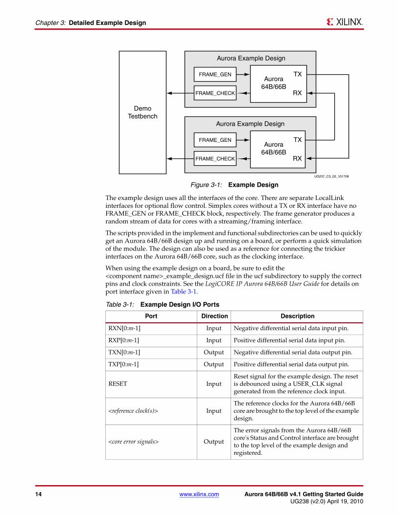
Example Design OverviewEach core includes an example design that uses the core in a simple data transfer system. In the example design, a frame generator is connected to the TX user interface, and a frame checker is connected to the RX user interface. Figure 3-1 shows a block diagram of the example design for a full-duplex core. Table 3-1, page 14 describes the ports of the example design.
14 www.xilinx.com Aurora 64B/66B v4.1 Getting Started GuideUG238 (v2.0) April 19, 2010
Chapter 3: Detailed Example Design
The example design uses all the interfaces of the core. There are separate LocalLink interfaces for optional flow control. Simplex cores without a TX or RX interface have no FRAME_GEN or FRAME_CHECK block, respectively. The frame generator produces a random stream of data for cores with a streaming/framing interface.
The scripts provided in the implement and functional subdirectories can be used to quickly get an Aurora 64B/66B design up and running on a board, or perform a quick simulation of the module. The design can also be used as a reference for connecting the trickier interfaces on the Aurora 64B/66B core, such as the clocking interface.
When using the example design on a board, be sure to edit the <component name>_example_design.ucf file in the ucf subdirectory to supply the correct pins and clock constraints. See the LogiCORE IP Aurora 64B/66B User Guide for details on port interface given in Table 3-1.
X-Ref Target - Figure 3-1
Figure 3-1: Example Design
Table 3-1: Example Design I/O Ports
Port Direction Description
RXN[0:m-1] Input Negative differential serial data input pin.
RXP[0:m-1] Input Positive differential serial data input pin.
TXN[0:m-1] Output Negative differential serial data output pin.
TXP[0:m-1] Output Positive differential serial data output pin.
RESET InputReset signal for the example design. The reset is debounced using a USER_CLK signal generated from the reference clock input.
<reference clock(s)> InputThe reference clocks for the Aurora 64B/66B core are brought to the top level of the example design.
<core error signals> Output
The error signals from the Aurora 64B/66B core's Status and Control interface are brought to the top level of the example design and registered.
DemoTestbench
Aurora Example Design
Aurora64B/66B
TX
RX
FRAME_GEN
FRAME_CHECK
Aurora Example Design
TX
RX
FRAME_GEN
FRAME_CHECK
Aurora64B/66B
UG237_C3_02_101708
Aurora 64B/66B v4.1 Getting Started Guide www.xilinx.com 15UG238 (v2.0) April 19, 2010
Example Design Overview
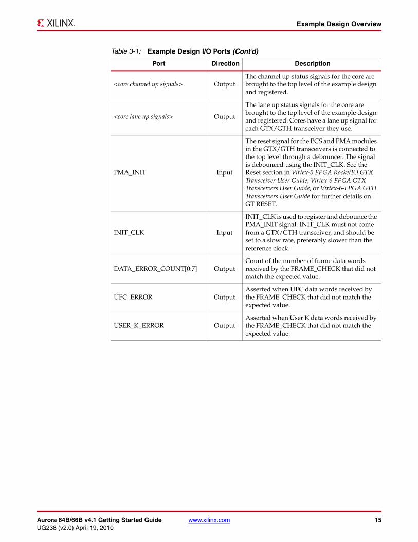
<core channel up signals> OutputThe channel up status signals for the core are brought to the top level of the example design and registered.
<core lane up signals> Output
The lane up status signals for the core are brought to the top level of the example design and registered. Cores have a lane up signal for each GTX/GTH transceiver they use.
PMA_INIT Input
The reset signal for the PCS and PMA modules in the GTX/GTH transceivers is connected to the top level through a debouncer. The signal is debounced using the INIT_CLK. See the Reset section in Virtex-5 FPGA RocketIO GTX Transceiver User Guide, Virtex-6 FPGA GTX Transceivers User Guide, or Virtex-6-FPGA GTH Transceivers User Guide for further details on GT RESET.
INIT_CLK Input
INIT_CLK is used to register and debounce the PMA_INIT signal. INIT_CLK must not come from a GTX/GTH transceiver, and should be set to a slow rate, preferably slower than the reference clock.
DATA_ERROR_COUNT[0:7] OutputCount of the number of frame data words received by the FRAME_CHECK that did not match the expected value.
UFC_ERROR OutputAsserted when UFC data words received by the FRAME_CHECK that did not match the expected value.
USER_K_ERROR OutputAsserted when User K data words received by the FRAME_CHECK that did not match the expected value.
Table 3-1: Example Design I/O Ports (Cont’d)
Port Direction Description

16 www.xilinx.com Aurora 64B/66B v4.1 Getting Started GuideUG238 (v2.0) April 19, 2010
Chapter 3: Detailed Example Design
FRAME_GEN
Framing TX Data InterfaceTo transmit the user data, the FRAME_GEN user data state machine manipulates control signals to do the following:
• After the Aurora interface is out of RESET and reaches CHANNEL_UP state, pseudo-random data is generated using user data linear feedback shift register (LFSR) and connected to TX_D bus.
• Generates the TX_SOF_N and TX_EOF_N for the current frame based on two counters. An 8-bit counter is used to determine the size of the frame and another 8-bit counter to keep track of number of user data bytes sent. Frame size counter is initialized and incremented by one for every frame.
• TX_REM bus is connected to lower bits of user data LFSR in order to generate SEP and SEP7 conditions.
• TX_SRC_RDY_N is asserted according to LocalLink protocol specification.
• User data state machine state transitions are controlled by TX_DST_RDY_N provided by Aurora's LocalLink interface.
• Various kinds of frame traffic are generated including single cycle frame where in TX_SOF_N, TX_EOF_N are asserted in same cycle.
Table 3-2 shows the FRAME_GEN framing user interface of the Aurora 64B/66B core, with LocalLink compliant ports for TX data.X-Ref Target - Figure 3-2
Figure 3-2: Aurora 64B/66B Core Framing TX Data Interface (FRAME_GEN)
USER_CLK
Framing TXData I/F
RESET
TX_DST_RDY_N
CHANNEL_UP
TX_D[0:(64n-1)]
TX_REM[0:r(n)]
TX_SOF_N
TX_EOF_N
TX_SRC_RDY_N
UG237_C3_03_062708
Aurora 64B/66B v4.1 Getting Started Guide www.xilinx.com 17UG238 (v2.0) April 19, 2010
FRAME_GEN
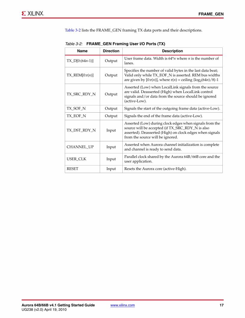
Table 3-2 lists the FRAME_GEN framing TX data ports and their descriptions.
Table 3-2: FRAME_GEN Framing User I/O Ports (TX)
Name Direction Description
TX_D[0:(64n-1)] OutputUser frame data. Width is 64*n where n is the number of lanes.
TX_REM[0:r(n)] OutputSpecifies the number of valid bytes in the last data beat; Valid only while TX_EOF_N is asserted. REM bus widths are given by [0:r(n)], where r(n) = ceiling {log2(64n)/8}-1
TX_SRC_RDY_N Output
Asserted (Low) when LocalLink signals from the source are valid. Deasserted (High) when LocalLink control signals and/or data from the source should be ignored (active-Low).
TX_SOF_N Output Signals the start of the outgoing frame data (active-Low).
TX_EOF_N Output Signals the end of the frame data (active-Low).
TX_DST_RDY_N Input
Asserted (Low) during clock edges when signals from the source will be accepted (if TX_SRC_RDY_N is also asserted). Deasserted (High) on clock edges when signals from the source will be ignored.
CHANNEL_UP Input Asserted when Aurora channel initialization is complete and channel is ready to send data.
USER_CLK Input Parallel clock shared by the Aurora 64B/66B core and the user application.
RESET Input Resets the Aurora core (active-High).
18 www.xilinx.com Aurora 64B/66B v4.1 Getting Started GuideUG238 (v2.0) April 19, 2010
Chapter 3: Detailed Example Design
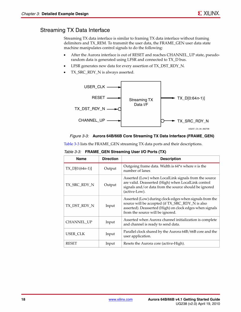
Streaming TX Data InterfaceStreaming TX data interface is similar to framing TX data interface without framing delimiters and TX_REM. To transmit the user data, the FRAME_GEN user data state machine manipulates control signals to do the following:
• After the Aurora interface is out of RESET and reaches CHANNEL_UP state, pseudo-random data is generated using LFSR and connected to TX_D bus.
• LFSR generates new data for every assertion of TX_DST_RDY_N.
• TX_SRC_RDY_N is always asserted.
Table 3-3 lists the FRAME_GEN streaming TX data ports and their descriptions.
X-Ref Target - Figure 3-3
Figure 3-3: Aurora 64B/66B Core Streaming TX Data Interface (FRAME_GEN)
Table 3-3: FRAME_GEN Streaming User I/O Ports (TX)
Name Direction Description
TX_D[0:(64n-1)] OutputOutgoing frame data. Width is 64*n where n is the number of lanes
TX_SRC_RDY_N Output
Asserted (Low) when LocalLink signals from the source are valid. Deasserted (High) when LocalLink control signals and/or data from the source should be ignored (active-Low).
TX_DST_RDY_N Input
Asserted (Low) during clock edges when signals from the source will be accepted (if TX_SRC_RDY_N is also asserted). Deasserted (High) on clock edges when signals from the source will be ignored.
CHANNEL_UP InputAsserted when Aurora channel initialization is complete and channel is ready to send data.
USER_CLK InputParallel clock shared by the Aurora 64B/66B core and the user application.
RESET Input Resets the Aurora core (active-High).
USER_CLK
Streaming TXData I/F
RESET
TX_DST_RDY_N
CHANNEL_UP
TX_D[0:64n-1)]
TX_SRC_RDY_N
UG237_C3_04_062708
Aurora 64B/66B v4.1 Getting Started Guide www.xilinx.com 19UG238 (v2.0) April 19, 2010
FRAME_GEN
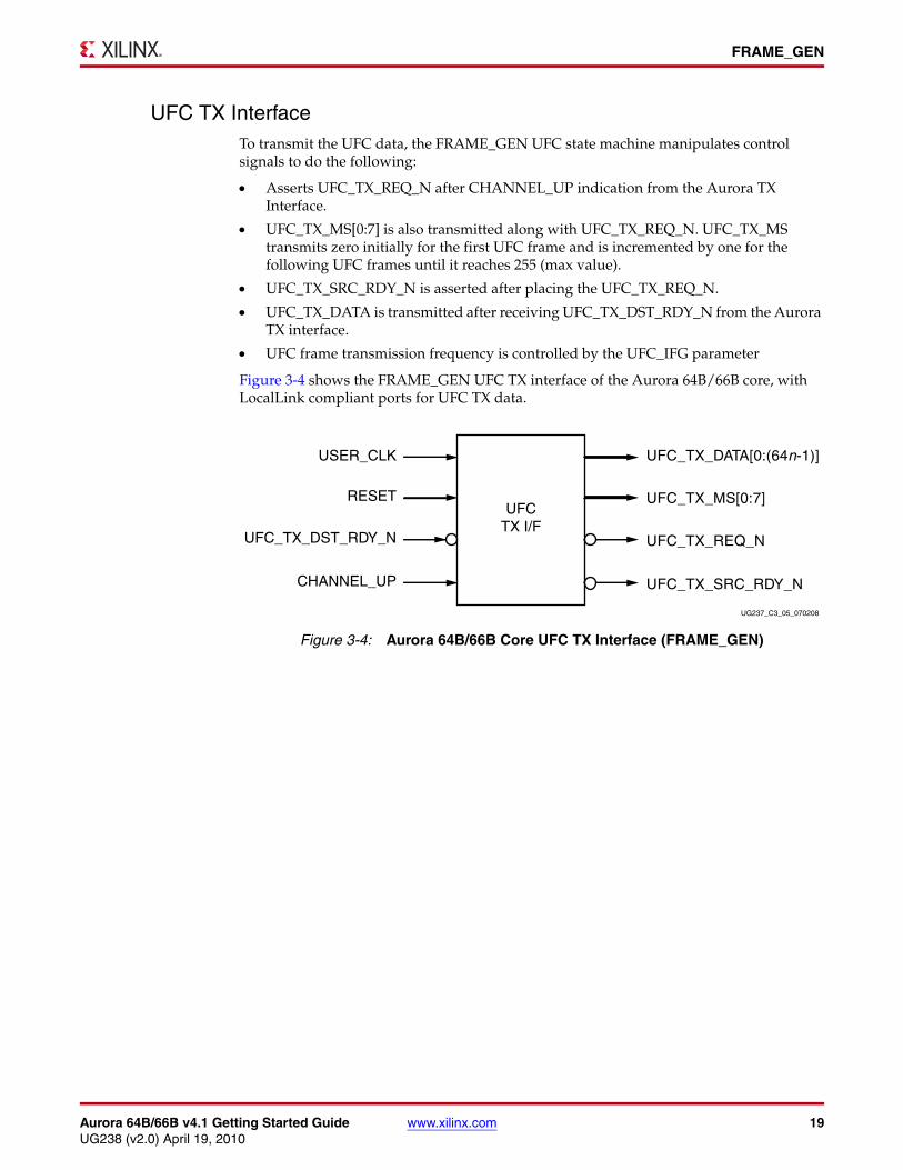
UFC TX InterfaceTo transmit the UFC data, the FRAME_GEN UFC state machine manipulates control signals to do the following:
• Asserts UFC_TX_REQ_N after CHANNEL_UP indication from the Aurora TX Interface.
• UFC_TX_MS[0:7] is also transmitted along with UFC_TX_REQ_N. UFC_TX_MS transmits zero initially for the first UFC frame and is incremented by one for the following UFC frames until it reaches 255 (max value).
• UFC_TX_SRC_RDY_N is asserted after placing the UFC_TX_REQ_N.
• UFC_TX_DATA is transmitted after receiving UFC_TX_DST_RDY_N from the Aurora TX interface.
• UFC frame transmission frequency is controlled by the UFC_IFG parameter
Figure 3-4 shows the FRAME_GEN UFC TX interface of the Aurora 64B/66B core, with LocalLink compliant ports for UFC TX data.X-Ref Target - Figure 3-4
Figure 3-4: Aurora 64B/66B Core UFC TX Interface (FRAME_GEN)
USER_CLK
UFCTX I/F
RESET
UFC_TX_DST_RDY_N
CHANNEL_UP
UFC_TX_DATA[0:(64n-1)]
UFC_TX_MS[0:7]
UFC_TX_REQ_N
UFC_TX_SRC_RDY_N
UG237_C3_05_070208
20 www.xilinx.com Aurora 64B/66B v4.1 Getting Started GuideUG238 (v2.0) April 19, 2010
Chapter 3: Detailed Example Design
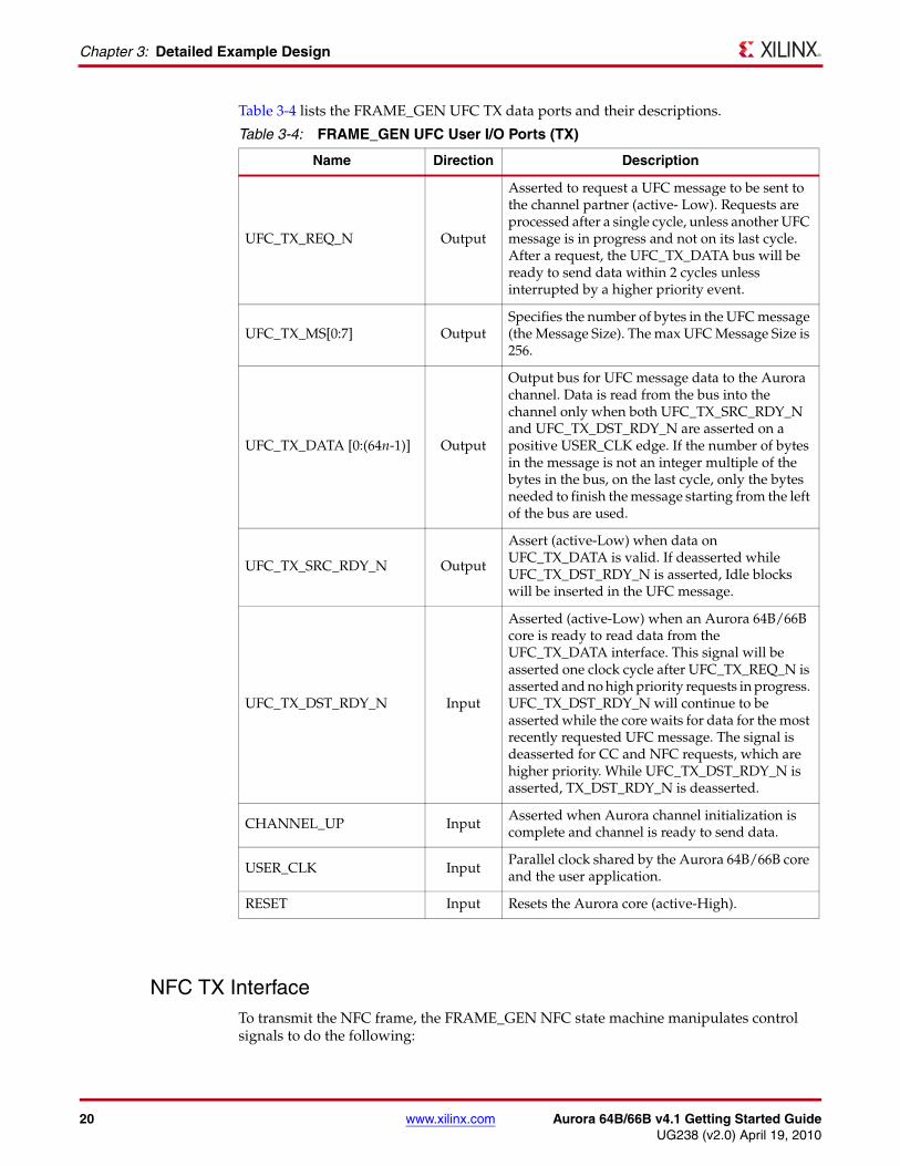
Table 3-4 lists the FRAME_GEN UFC TX data ports and their descriptions.
NFC TX InterfaceTo transmit the NFC frame, the FRAME_GEN NFC state machine manipulates control signals to do the following:
Table 3-4: FRAME_GEN UFC User I/O Ports (TX)
Name Direction Description
UFC_TX_REQ_N Output
Asserted to request a UFC message to be sent to the channel partner (active- Low). Requests are processed after a single cycle, unless another UFC message is in progress and not on its last cycle. After a request, the UFC_TX_DATA bus will be ready to send data within 2 cycles unless interrupted by a higher priority event.
UFC_TX_MS[0:7] OutputSpecifies the number of bytes in the UFC message (the Message Size). The max UFC Message Size is 256.
UFC_TX_DATA [0:(64n-1)] Output
Output bus for UFC message data to the Aurora channel. Data is read from the bus into the channel only when both UFC_TX_SRC_RDY_N and UFC_TX_DST_RDY_N are asserted on a positive USER_CLK edge. If the number of bytes in the message is not an integer multiple of the bytes in the bus, on the last cycle, only the bytes needed to finish the message starting from the left of the bus are used.
UFC_TX_SRC_RDY_N Output
Assert (active-Low) when data on UFC_TX_DATA is valid. If deasserted while UFC_TX_DST_RDY_N is asserted, Idle blocks will be inserted in the UFC message.
UFC_TX_DST_RDY_N Input
Asserted (active-Low) when an Aurora 64B/66B core is ready to read data from the UFC_TX_DATA interface. This signal will be asserted one clock cycle after UFC_TX_REQ_N is asserted and no high priority requests in progress. UFC_TX_DST_RDY_N will continue to be asserted while the core waits for data for the most recently requested UFC message. The signal is deasserted for CC and NFC requests, which are higher priority. While UFC_TX_DST_RDY_N is asserted, TX_DST_RDY_N is deasserted.
CHANNEL_UP Input Asserted when Aurora channel initialization is complete and channel is ready to send data.
USER_CLK InputParallel clock shared by the Aurora 64B/66B core and the user application.
RESET Input Resets the Aurora core (active-High).

Aurora 64B/66B v4.1 Getting Started Guide www.xilinx.com 21UG238 (v2.0) April 19, 2010
FRAME_GEN
• NFC state machine waits until TX user data transmission and enters into NFC XON mode.
• NFC PAUSE value is transmitted along with NFC_REQ_N.
• After predefined period of time, NFC state machine enters into NFC XOFF mode. NFC_XOFF is asserted.
• NFC state transitions are governed by NFC_ACK_N
• NFC frame transmission frequency is controlled by NFC_IFG parameter.
Figure 3-5 shows the FRAME_GEN NFC TX interface of the Aurora 64B/66B core, with LocalLink compliant ports for NFC TX data.
Table 3-5 lists the FRAME_GEN NFC TX data ports and their descriptions.
X-Ref Target - Figure 3-5
Figure 3-5: Aurora 64B/66B Core NFC TX Interface (FRAME_GEN)
Table 3-5: FRAME_GEN NFC User I/O Ports (TX)
Name Direction Description
NFC_REQ_N OutputAsserted to request an NFC message to be sent to the channel partner (active-Low). Must be held until NFC_ACK_N is asserted.
NFC_PAUSE [0:7] Output
Indicates how many USER_CLK cycles the channel partner must wait before it can send data when it receives the NFC message. Must be held until NFC_ACK_N is asserted. The number of USER_CLK cycles without data is equal to NFC_PAUSE + 1.
NFC_XOFF OutputAssert to send an XOFF message, requesting that the channel partner stop sending data until it receives a non-XOFF NFC message or is reset.
NFC_ACK_N Input Asserted when an Aurora core accepts an NFC request (active-Low).
CHANNEL_UP Input Asserted when Aurora channel initialization is complete and channel is ready to send data.
USER_CLK Input Parallel clock shared by the Aurora 64B/66B core and the user application.
RESET Input Resets the Aurora core (active-High).
USER_CLK
NFCTX I/F
RESET
NFC_ACK_N
CHANNEL_UP
NFC_XOFF
NFC_PAUSE[0:7]
NFC_REQ_N
UG237_C3_06_070208
22 www.xilinx.com Aurora 64B/66B v4.1 Getting Started GuideUG238 (v2.0) April 19, 2010
Chapter 3: Detailed Example Design
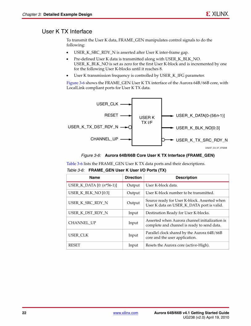
User K TX InterfaceTo transmit the User K data, FRAME_GEN manipulates control signals to do the following:
• USER_K_SRC_RDY_N is asserted after User K inter-frame gap.
• Pre-defined User K data is transmitted along with USER_K_BLK_NO. USER_K_BLK_NO is set as zero for the first User K-block and is incremented by one for the following User K-blocks until it reaches 8.
• User K transmission frequency is controlled by USER_K_IFG parameter.
Figure 3-6 shows the FRAME_GEN User K TX interface of the Aurora 64B/66B core, with LocalLink compliant ports for User K TX data.
Table 3-6 lists the FRAME_GEN User K TX data ports and their descriptions.
X-Ref Target - Figure 3-6
Figure 3-6: Aurora 64B/66B Core User K TX Interface (FRAME_GEN)
Table 3-6: FRAME_GEN User K User I/O Ports (TX)
Name Direction Description
USER_K_DATA [0: (n*56-1)] Output User K-block data.
USER_K_BLK_NO [0:3] Output User K-block number to be transmitted.
USER_K_SRC_RDY_N Output Source ready for User K-block. Asserted when User K data on USER_K_DATA port is valid.
USER_K_DST_RDY_N Input Destination Ready for User K-blocks.
CHANNEL_UP InputAsserted when Aurora channel initialization is complete and channel is ready to send data.
USER_CLK InputParallel clock shared by the Aurora 64B/66B core and the user application.
RESET Input Resets the Aurora core (active-High).
USER_CLK
USER KTX I/F
RESET
USER_K_TX_DST_RDY_N
CHANNEL_UP
USER_K_DATA[0-(56n-1)]
USER_K_BLK_NO[0:3]
USER_K_TX_SRC_RDY_N
UG237_C3_07_070208
Aurora 64B/66B v4.1 Getting Started Guide www.xilinx.com 23UG238 (v2.0) April 19, 2010
FRAME_CHECK
FRAME_CHECK
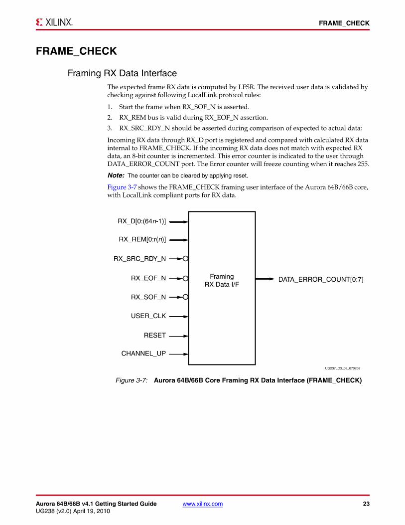
Framing RX Data InterfaceThe expected frame RX data is computed by LFSR. The received user data is validated by checking against following LocalLink protocol rules:
1. Start the frame when RX_SOF_N is asserted.
2. RX_REM bus is valid during RX_EOF_N assertion.
3. RX_SRC_RDY_N should be asserted during comparison of expected to actual data:
Incoming RX data through RX_D port is registered and compared with calculated RX data internal to FRAME_CHECK. If the incoming RX data does not match with expected RX data, an 8-bit counter is incremented. This error counter is indicated to the user through DATA_ERROR_COUNT port. The Error counter will freeze counting when it reaches 255.
Note: The counter can be cleared by applying reset.
Figure 3-7 shows the FRAME_CHECK framing user interface of the Aurora 64B/66B core, with LocalLink compliant ports for RX data.X-Ref Target - Figure 3-7
Figure 3-7: Aurora 64B/66B Core Framing RX Data Interface (FRAME_CHECK)
RX_D[0:(64n-1)]
FramingRX Data I/F
RX_REM[0:r(n)]
RX_SRC_RDY_N
RX_EOF_N
RX_SOF_N
USER_CLK
RESET
CHANNEL_UP
DATA_ERROR_COUNT[0:7]
UG237_C3_08_070208
24 www.xilinx.com Aurora 64B/66B v4.1 Getting Started GuideUG238 (v2.0) April 19, 2010
Chapter 3: Detailed Example Design
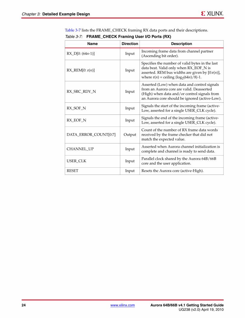
Table 3-7 lists the FRAME_CHECK framing RX data ports and their descriptions.
Table 3-7: FRAME_CHECK Framing User I/O Ports (RX)
Name Direction Description
RX_D[0: (64n-1)] InputIncoming frame data from channel partner (Ascending bit order).
RX_REM[0: r(n)] Input
Specifies the number of valid bytes in the last data beat. Valid only when RX_EOF_N is asserted. REM bus widths are given by [0:r(n)], where r(n) = ceiling {log2(64n)/8}-1.
RX_SRC_RDY_N Input
Asserted (Low) when data and control signals from an Aurora core are valid. Deasserted (High) when data and/or control signals from an Aurora core should be ignored (active-Low).
RX_SOF_N InputSignals the start of the incoming frame (active-Low, asserted for a single USER_CLK cycle).
RX_EOF_N InputSignals the end of the incoming frame (active-Low, asserted for a single USER_CLK cycle).
DATA_ERROR_COUNT[0:7] OutputCount of the number of RX frame data words received by the frame checker that did not match the expected value.
CHANNEL_UP InputAsserted when Aurora channel initialization is complete and channel is ready to send data.
USER_CLK InputParallel clock shared by the Aurora 64B/66B core and the user application.
RESET Input Resets the Aurora core (active-High).
Aurora 64B/66B v4.1 Getting Started Guide www.xilinx.com 25UG238 (v2.0) April 19, 2010
FRAME_CHECK
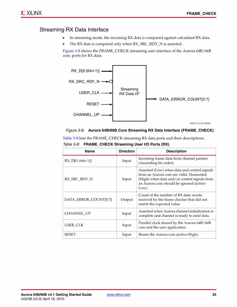
Streaming RX Data Interface• In streaming mode, the incoming RX data is compared against calculated RX data.
• The RX data is compared only when RX_SRC_RDY_N is asserted.
Figure 3-8 shows the FRAME_CHECK streaming user interface of the Aurora 64B/66B core, ports for RX data.
Table 3-8 lists the FRAME_CHECK streaming RX data ports and their descriptions.
X-Ref Target - Figure 3-8
Figure 3-8: Aurora 64B/66B Core Streaming RX Data Interface (FRAME_CHECK)
Table 3-8: FRAME_CHECK Streaming User I/O Ports (RX)
Name Direction Description
RX_D[0: (64n-1)] InputIncoming frame data from channel partner (Ascending bit order).
RX_SRC_RDY_N Input
Asserted (Low) when data and control signals from an Aurora core are valid. Deasserted (High) when data and/or control signals from an Aurora core should be ignored (active-Low).
DATA_ERROR_COUNT[0:7] OutputCount of the number of RX data words received by the frame checker that did not match the expected value.
CHANNEL_UP InputAsserted when Aurora channel initialization is complete and channel is ready to send data.
USER_CLK InputParallel clock shared by the Aurora 64B/66B core and the user application.
RESET Input Resets the Aurora core (active-High).
RX_D[0:(64n-1)]
StreamingRX Data I/F
RX_SRC_RDY_N
USER_CLK
RESET
CHANNEL_UP
DATA_ERROR_COUNT[0:7]
UG237_C3_09_070208

26 www.xilinx.com Aurora 64B/66B v4.1 Getting Started GuideUG238 (v2.0) April 19, 2010
Chapter 3: Detailed Example Design
UFC RX Interface• Expected UFC RX data is computed by LFSR.
• Error checking and counter logic is similar to that of “Framing RX Data Interface.”
• If the incoming UFC_RX_DATA does not match with expected RX UFC data, an 8-bit error counter will be incremented.
• The error counter is indicated to the user through the UFC_ERROR_COUNT port.
Figure 3-9 shows the FRAME_CHECK UFC RX interface of the Aurora 64B/66B core, with LocalLink compliant ports for UFC RX data.
Table 3-9 lists the FRAME_CHECK UFC RX data ports and their descriptions.
X-Ref Target - Figure 3-9
Figure 3-9: Aurora 64B/66B Core UFC RX Interface (FRAME_CHECK)
Table 3-9: FRAME_CHECK UFC User I/O Ports (RX)
Name Direction Description
UFC_RX_DATA [0: (64n-1)] InputIncoming UFC message data from the channel partner.
UFC_RX_REM [0: r(n)] Input
Specifies the number of valid bytes of data presented on the UFC_RX_DATA port on the last word of a UFC message. Valid only when UFC_RX_EOF_N is asserted. n = 256 bytes max. REM bus widths are given {log2(64n)/8}-1.
UFC_RX_SRC_RDY_N Input
Asserted when the values on the UFC_RX_DATA port is valid. When this signal is not asserted, all values on the UFC_RX_DATA port should be ignored (active-Low).
UFC_RX_SOF_N InputSignals the start of the incoming UFC message (active-Low).
UFC_RX_EOF_N InputSignals the end of the incoming UFC message (active-Low).
UFC_RX_DATA[0:(64n-1)]
UFCRX I/F
UFC_RX_REM[0:r(n)]
UFC_RX_SRC_RDY_N
UFC_RX_EOF_N
UFC_RX_SOF_N
USER_CLK
RESET
UFC_ERROR_COUNT[0:7]
UG237_C3_10_071608
CHANNEL_UP
Aurora 64B/66B v4.1 Getting Started Guide www.xilinx.com 27UG238 (v2.0) April 19, 2010
FRAME_CHECK
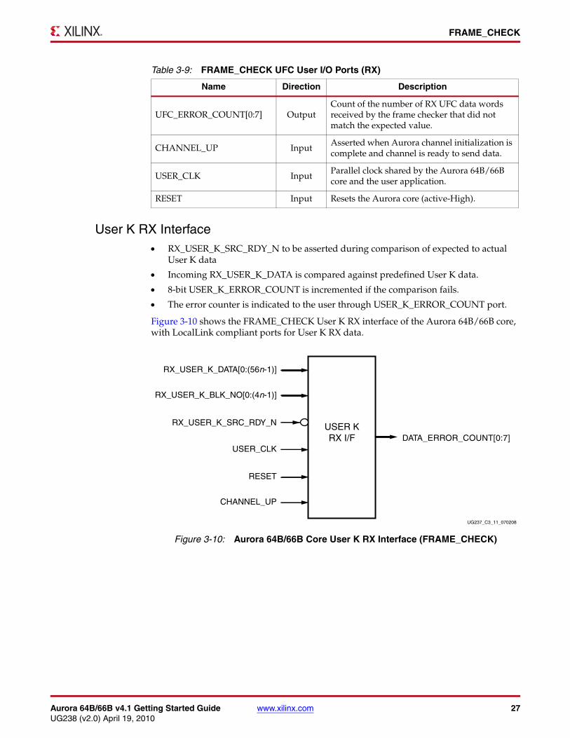
User K RX Interface• RX_USER_K_SRC_RDY_N to be asserted during comparison of expected to actual
User K data
• Incoming RX_USER_K_DATA is compared against predefined User K data.
• 8-bit USER_K_ERROR_COUNT is incremented if the comparison fails.
• The error counter is indicated to the user through USER_K_ERROR_COUNT port.
Figure 3-10 shows the FRAME_CHECK User K RX interface of the Aurora 64B/66B core, with LocalLink compliant ports for User K RX data.
UFC_ERROR_COUNT[0:7] OutputCount of the number of RX UFC data words received by the frame checker that did not match the expected value.
CHANNEL_UP InputAsserted when Aurora channel initialization is complete and channel is ready to send data.
USER_CLK InputParallel clock shared by the Aurora 64B/66B core and the user application.
RESET Input Resets the Aurora core (active-High).
Table 3-9: FRAME_CHECK UFC User I/O Ports (RX)
Name Direction Description
X-Ref Target - Figure 3-10
Figure 3-10: Aurora 64B/66B Core User K RX Interface (FRAME_CHECK)
RX_USER_K_DATA[0:(56n-1)]
USER KRX I/F
RX_USER_K_BLK_NO[0:(4n-1)]
RX_USER_K_SRC_RDY_N
USER_CLK
RESET
CHANNEL_UP
DATA_ERROR_COUNT[0:7]
UG237_C3_11_070208
28 www.xilinx.com Aurora 64B/66B v4.1 Getting Started GuideUG238 (v2.0) April 19, 2010
Chapter 3: Detailed Example Design
Table 3-10 lists the FRAME_CHECK User K RX data ports and their descriptions.
The Aurora 64B/66B example design has been tested with XST for synthesis and Mentor Graphics ModelSim for simulation.
Generating the CoreTo generate an Aurora 64B/66B core with default values using the CORE Generator™ software:
1. Start the CORE Generator software from a required directory.
For help starting and using the CORE Generator software, see CORE Generator Help in the ISE® software documentation.
2. Choose File > New Project.
3. Type a project name.
4. To set project options:
On the Part tab, for Family select Virtex5. For Device, select an appropriate device that supports GTX transceivers, such as xc5vfx70t.
Note: If an unsupported silicon family is selected, the Aurora 64B/66B appears light grey in the taxonomy tree and cannot be customized. Only devices containing GTX/GTH transceivers are supported by the core.
No further project options need to be set.
Optionally, on the Generation tab, set the Design Entry pull-down to Verilog.
5. After creating the project, locate the Aurora 64B/66B core v4.1 in the taxonomy tree under:
/Communication_&_Networking/Serial_Interfaces
6. Double-click the core for generation.
Table 3-10: FRAME_CHECK User K User I/O Ports (RX)
Name Direction Description
RX_USER_K_SRC_RDY_N Input Receive Source Ready for User K-block.
RX_USER_K_DATA [0:(n*56-1)] InputReceive User K-blocks from the Aurora lane.
RX_USER_K_BLK_NO [0:(n*4-1)] Input Received User K-block number.
USER_K_ERROR_COUNT[0:7] OutputCount of the number of RX User K data words received by the frame checker that did not match the expected value.
CHANNEL_UP InputAsserted when Aurora channel initialization is complete and channel is ready to send data.
USER_CLK InputParallel clock shared by the Aurora 64B/66B core and the user application.
RESET Input Resets the Aurora core (active-High).
Aurora 64B/66B v4.1 Getting Started Guide www.xilinx.com 29UG238 (v2.0) April 19, 2010
Generating the Core
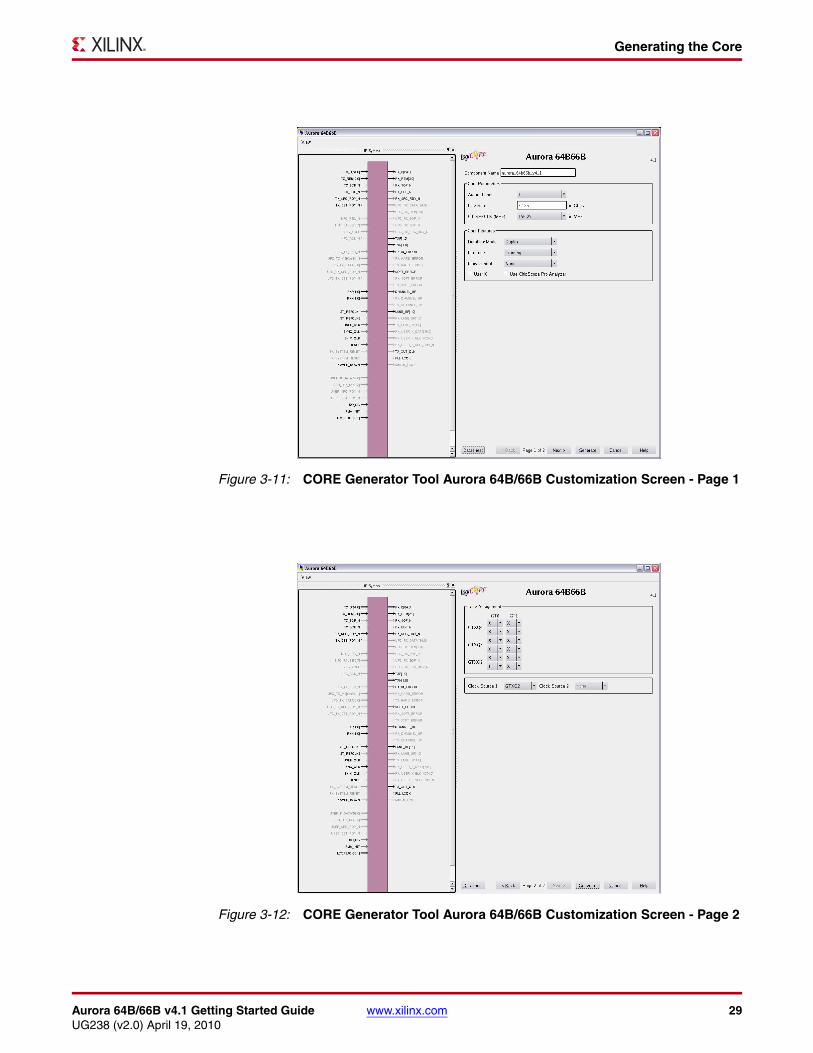
X-Ref Target - Figure 3-11
Figure 3-11: CORE Generator Tool Aurora 64B/66B Customization Screen - Page 1
X-Ref Target - Figure 3-12
Figure 3-12: CORE Generator Tool Aurora 64B/66B Customization Screen - Page 2

30 www.xilinx.com Aurora 64B/66B v4.1 Getting Started GuideUG238 (v2.0) April 19, 2010
Chapter 3: Detailed Example Design
7. In the Component Name field, enter a name for the core instance. This example uses the name aurora_64b66b_v4_1.
8. Click Generate.
The core and its supporting files, including the example design, are generated in the project directory. For detailed information about the core files, see the LogiCORE IP Aurora 64B/66B User Guide.
Simulating the Example DesignThe Aurora 64B/66B core provides a quick way to simulate and observe the behavior of the core using the provided example design. Prior to simulating the core, the functional (gate-level) simulation models must be generated. You must compile all source files in the following directories to a single library as shown in Table 3-11. Refer to the Synthesis and Verification Design Guide for ISE 12.1 software for instructions on how to compile ISE software simulation libraries.
The Aurora 64B/66B core provides a command line script to simulate the example design. To run a VHDL or Verilog ModelSim simulation of the Aurora 64B/66B core, use the following instructions:
1. Launch the ModelSim simulator and set the current directory to:
<project directory>/aurora_64b66b_v4_1/simulation/functional
2. Set the MTI_LIBS variable:
modelsim> setenv MTI_LIBS <path to compiled libraries>
3. Launch the simulation script:
modelsim> do simulate_mti.do
The ModelSim script compiles the example design and testbench, and adds the relevant signals to the wave window. After the design is compiled and the wave window is displayed, run the simulation to see the Aurora 64B/66B core power up, followed by Aurora 64B/66B channel initialization and data transfer. Data transfer begins after the CHANNEL_UP signal goes High.
Table 3-11: Required Simulation Libraries
HDL Library Source Directories
Verilog UNISIMS_VER<Xilinx dir>/verilog/src/unisims<Xilinx dir>/ secureip/<SIMULATOR>
VHDL UNISIM<Xilinx dir>/vhdl/src/unisims<Xilinx dir>/ secureip/<SIMULATOR>
Notes: 1. SIMULATOR can be Modelsim.
Aurora 64B/66B v4.1 Getting Started Guide www.xilinx.com 31UG238 (v2.0) April 19, 2010
Implementing the Example Design
Implementing the Example DesignAfter the core is generated, the design can be processed by the Xilinx implementation tools. The generated output files include several scripts to assist the user in running the Xilinx software.
From the command prompt, navigate to the project directory and type the following:
For Windows
ms-dos> cd aurora_64b66b_v4_1\implement
ms-dos> .\implement.bat
For Linux
% cd aurora_64b66b_v4_1/implement
%./implement.sh
These commands execute a script that synthesizes, translates, maps, place-and-routes the example design and produces a bitmap file. The resulting files are placed in the results directory created within the implement directory.
Using ChipScope Pro Cores with the Aurora 64B/66B CoreThe ChipScope™ Pro ICON, ILA, and VIO cores aid in debugging and validating the design in board. To assist with debugging, these cores are provided with the Aurora 64B/66B core, select the CHIPSCOPE option from the core GUI to include it as a part of the example design.
32 www.xilinx.com Aurora 64B/66B v4.1 Getting Started GuideUG238 (v2.0) April 19, 2010
Chapter 3: Detailed Example Design
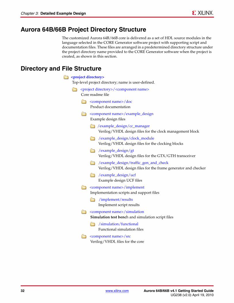
Aurora 64B/66B Project Directory StructureThe customized Aurora 64B/66B core is delivered as a set of HDL source modules in the language selected in the CORE Generator software project with supporting script and documentation files. These files are arranged in a predetermined directory structure under the project directory name provided to the CORE Generator software when the project is created, as shown in this section.
Directory and File Structure<project directory>topdirectory
Top-level project directory; name is user-defined.
<project directory>/<component name>Core readme file
<component name>/docProduct documentation
<component name>/example_designExample design files
/example_design/cc_managerVerilog/VHDL design files for the clock management block
/example_design/clock_module Verilog/VHDL design files for the clocking blocks
/example_design/gtVerilog/VHDL design files for the GTX/GTH transceiver
/example_design/traffic_gen_and_checkVerilog/VHDL design files for the frame generator and checker
/example_design/ucfExample design UCF files
<component name>/implementImplementation scripts and support files
/implement/resultsImplement script results
<component name>/simulationSimulation test bench and simulation script files
/simulation/functionalFunctional simulation files
<component name>/srcVerilog/VHDL files for the core
Aurora 64B/66B v4.1 Getting Started Guide www.xilinx.com 33UG238 (v2.0) April 19, 2010
Directory and File Contents
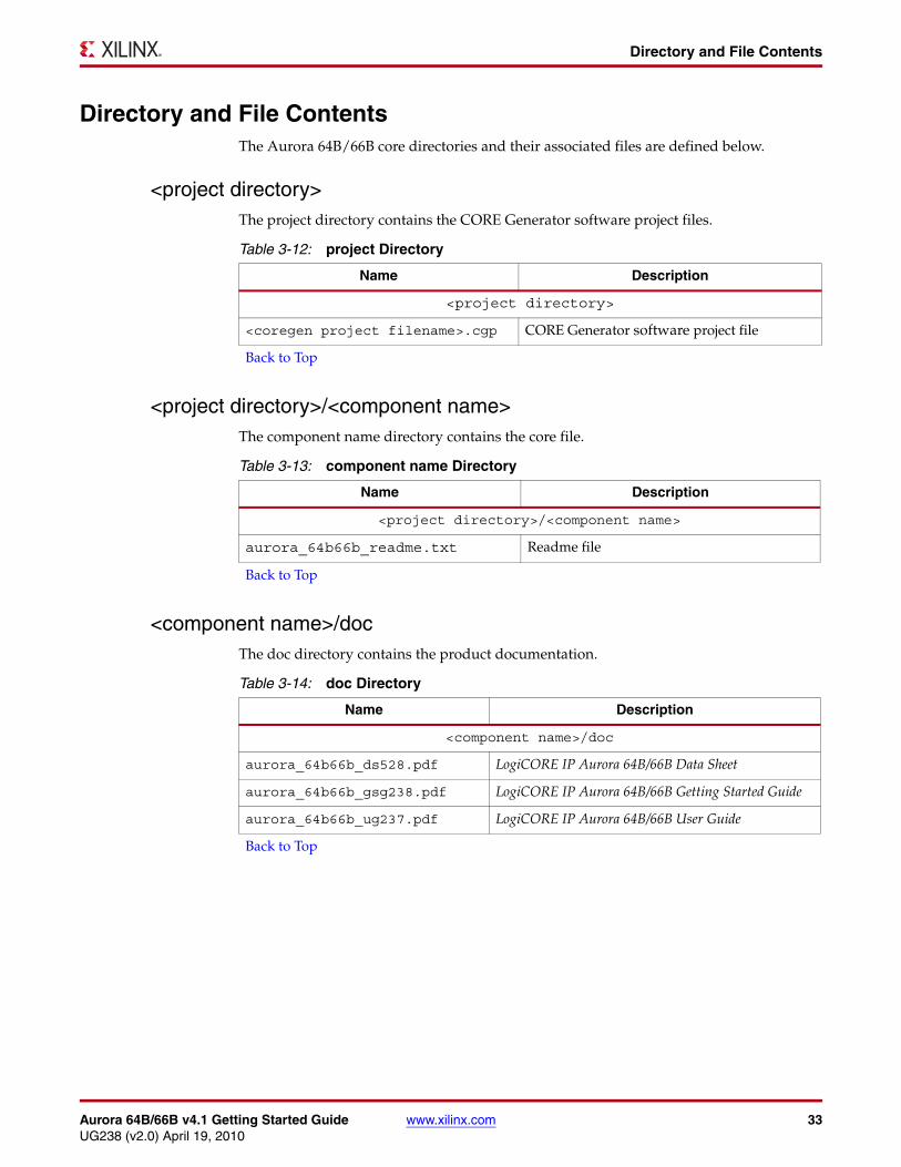
Directory and File ContentsThe Aurora 64B/66B core directories and their associated files are defined below.
<project directory>The project directory contains the CORE Generator software project files.
<project directory>/<component name>The component name directory contains the core file.
<component name>/docThe doc directory contains the product documentation.
Table 3-12: project Directory
Name Description
<project directory>
<coregen project filename>.cgp CORE Generator software project file
Back to Top
Table 3-13: component name Directory
Name Description
<project directory>/<component name>
aurora_64b66b_readme.txt Readme file
Back to Top
Table 3-14: doc Directory
Name Description
<component name>/doc
aurora_64b66b_ds528.pdf LogiCORE IP Aurora 64B/66B Data Sheet
aurora_64b66b_gsg238.pdf LogiCORE IP Aurora 64B/66B Getting Started Guide
aurora_64b66b_ug237.pdf LogiCORE IP Aurora 64B/66B User Guide
Back to Top
34 www.xilinx.com Aurora 64B/66B v4.1 Getting Started GuideUG238 (v2.0) April 19, 2010
Chapter 3: Detailed Example Design
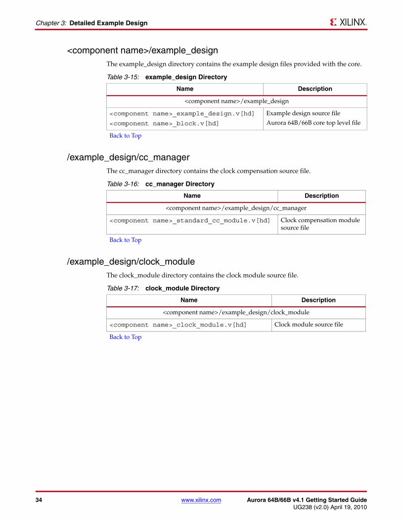
<component name>/example_designThe example_design directory contains the example design files provided with the core..
/example_design/cc_managerThe cc_manager directory contains the clock compensation source file.
/example_design/clock_moduleThe clock_module directory contains the clock module source file.
Table 3-15: example_design Directory
Name Description
<component name>/example_design
<component name>_example_design.v[hd]
<component name>_block.v[hd]
Example design source file
Aurora 64B/66B core top level file
Back to Top
Table 3-16: cc_manager Directory
Name Description
<component name>/example_design/cc_manager
<component name>_standard_cc_module.v[hd] Clock compensation module source file
Back to Top
Table 3-17: clock_module Directory
Name Description
<component name>/example_design/clock_module
<component name>_clock_module.v[hd] Clock module source file
Back to Top
Aurora 64B/66B v4.1 Getting Started Guide www.xilinx.com 35UG238 (v2.0) April 19, 2010
Directory and File Contents
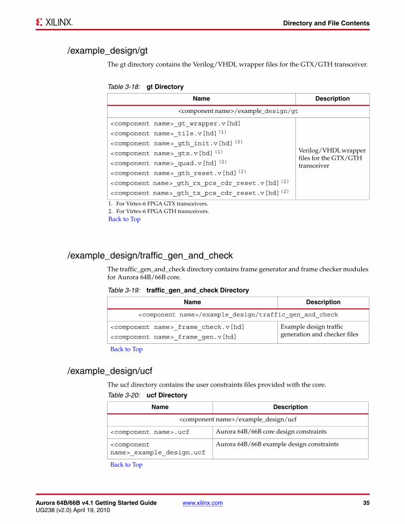
/example_design/gtThe gt directory contains the Verilog/VHDL wrapper files for the GTX/GTH transceiver.
/example_design/traffic_gen_and_checkThe traffic_gen_and_check directory contains frame generator and frame checker modules for Aurora 64B/66B core.
/example_design/ucfThe ucf directory contains the user constraints files provided with the core.
Table 3-18: gt Directory
Name Description
<component name>/example_design/gt
<component name>_gt_wrapper.v[hd]
<component name>_tile.v[hd](1)
<component name>_gth_init.v[hd](2)
<component name>_gtx.v[hd](1)
<component name>_quad.v[hd](2)
<component name>_gth_reset.v[hd](2)
<component name>_gth_rx_pcs_cdr_reset.v[hd](2)
<component name>_gth_tx_pcs_cdr_reset.v[hd](2)
Verilog/VHDL wrapper files for the GTX/GTH transceiver
1. For Virtex-6 FPGA GTX transceivers.2. For Virtex-6 FPGA GTH transceivers.Back to Top
Table 3-19: traffic_gen_and_check Directory
Name Description
<component name>/example_design/traffic_gen_and_check
<component name>_frame_check.v[hd]
<component name>_frame_gen.v[hd]
Example design traffic generation and checker files
Back to Top
Table 3-20: ucf Directory
Name Description
<component name>/example_design/ucf
<component name>.ucf Aurora 64B/66B core design constraints
<component name>_example_design.ucf
Aurora 64B/66B example design constraints
Back to Top
36 www.xilinx.com Aurora 64B/66B v4.1 Getting Started GuideUG238 (v2.0) April 19, 2010
Chapter 3: Detailed Example Design
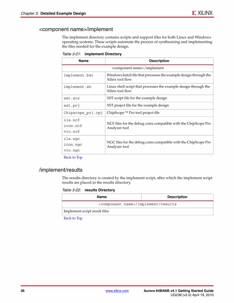
<component name>/implementThe implement directory contains scripts and support files for both Linux and Windows operating systems. These scripts automate the process of synthesizing and implementing the files needed for the example design.
/implement/resultsThe results directory is created by the implement script, after which the implement script results are placed in the results directory.
Table 3-21: implement Directory
Name Description
<component name>/implement
implement.bat Windows batch file that processes the example design through the Xilinx tool flow
implement.sh Linux shell script that processes the example design through the Xilinx tool flow
xst.scr XST script file for the example design
xst.prj XST project file for the example design
Chipscope_prj.cpj ChipScope™ Pro tool project file
ila.ncf
icon.ncf
vio.ncf
NCF files for the debug cores compatible with the ChipScope Pro Analyzer tool
ila.ngc
icon.ngc
vio.ngc
NGC files for the debug cores compatible with the ChipScope Pro Analyzer tool
Back to Top
Table 3-22: results Directory
Name Description
<component name>/implement/results
Implement script result files
Back to Top

Aurora 64B/66B v4.1 Getting Started Guide www.xilinx.com 37UG238 (v2.0) April 19, 2010
Directory and File Contents
<component name>/simulationThe simulation directory contains the test bench files for the example design.
/simulation/functionalThe functional directory contains functional simulation scripts provided with the core.
/simulation/timingThe timing directory contains timing simulation scripts provided with the core.
Table 3-23: simulation Directory
Name Description
<component name>/simulation
demo_tb.v[hd] Test bench file for simulating the example design
Back to Top
Table 3-24: functional Directory
Name Description
<component name>/simulation/functional
simulate_mti.do ModelSim macro file that compiles the example design sources, the structural simulation model, and the demonstration test bench then runs the functional simulation to completion
wave_mti.do ModelSim macro file that opens a Wave window
Back to Top
Table 3-25: functional Directory
Name Description
<component name>/simulation/timing
simulate_mti.do ModelSim macro file that compiles the .sdf files of the core and the demonstration test bench then runs the timing simulation to completion
wave_mti.do ModelSim macro file that opens a Wave window
Back to Top

38 www.xilinx.com Aurora 64B/66B v4.1 Getting Started GuideUG238 (v2.0) April 19, 2010
Chapter 3: Detailed Example Design
<component name>/srcThe src directory contains the source files related to the Aurora example design.
Table 3-26: src Directory
Name Description
<component name>/src
<component name>_64B66B.v[hd]
<component name>_64B66B_descrambler.v[hd]
<component name>_64B66B_scrambler.v[hd]
<component name>_aurora_lane.v[hd]
<component name>_aurora_pkg.vhd (VHDL Only)
<component name>_aurora_to_gtx.v[hd]
<component name>_block_sync_sm.v[hd]
<component name>_cbcc_gtx_6466.v[hd]
<component name>_ch_bond_code_gen.v[hd]
<component name>_channel_error_detect.v[hd]
<component name>_channel_init_sm.v[hd]
<component name>_error_detect.v[hd]
<component name>_global_logic.v[hd]
<component name>_gtx_to_aurora.v[hd]
<component name>_lane_init_sm.v[hd]
<component name>_rx_ll.v[hd]
<component name>_rx_ll_datapath.v[hd]
<component name>_sym_dec.v[hd]
<component name>_sym_gen.v[hd]
<component name>_tx_ll.v[hd]
<component name>_tx_ll_control_sm.v[hd]
<component name>_tx_ll_datapath.v[hd]
<component name>_tx_gearbox.v[hd]
<component name>_rx_gearbox.v[hd]
Aurora 64B/66B source files
Back to Top
Top Related