


Languages
Pages
Legal

Visit us online to register your warrantywww.thermoscientific.com/labwarranty
User M
anual
Locator and Locator PlusCryogenic Storage Vessel with or withoutUltrasonic Level MonitorOperation Manual and Parts List LT509X9 (7018141) Rev. 5
Thermo Scientific
MANUAL NUMBER LT509X9 (7018141)
5 41864 11/07/17 Removed CE mark and info bpg
4 40578 2/23/16 Clarified Do Not Roll warning ccs
3 -- 10/27/15 Updated symbols and labels, added cautions ccs
2 31623 5/15/15 Added caution for moving vessel in Section 3 ccs
1 31528 9/15/14 Updated conformity specs and declaration ccs
0 27564 1/31/14 Original - new PCBA design ccs
Preface
Cryogenic Storage Vessel i
Locator Catalog Number LocatorModel Name
CY50925 w/o Monitor 8141 Locator Jr
CY50935 w/o Monitor 8143 Locator 4
CY50985 w/o Monitor 8197 Locator 6
CY50945 w/o Monitor 8145 Locator 8
CY509105 w/ Monitor 8201 Locator Jr.
CY509105CN w/ Monitor 8202 Locator Jr. China
CY509107 w/ Monitor 8246 Locator 4
CY509107CN w/ Monitor 8247 Locator 4 China
CY509113 w/ Monitor 8198 Locator 6
CY509110 w/ Monitor 8211 Locator 8
CY509110CN w/ Monitor 8212 Locator 8 China
Locator Plus Catalog Number Locator PlusModel Name
CY50925-70 w/o Monitor 8142 Locator Jr Plus
CY50935-70 w/o Monitor 8144 Locator 4 Plus
CY50985-70 w/o Monitor 8147 Locator 6 Plus
CY50945-70 w/o Monitor 8146 Locator 8 Plus
CY509106 w/ Monitor 8237 Locator Jr Plus
CY509106CN w/ Monitor 8238 Locator Jr Plus China
CY509108 w/ Monitor 8207 Locator 4 Plus
CY509108CN w/ Monitor 8208 Locator 4 Plus China
CY509109 w/ Monitor 8209 Locator 6 Plus
CY509109CN w/ Monitor 8210 Locator 6 Plus China
CY509111 w/ Monitor 8213 Locator 8 Plus
CY509111CN w/ Monitor 8214 Locator 8 Plus China
Thermo Scientificii Cryogenic Storage Vessel
Preface
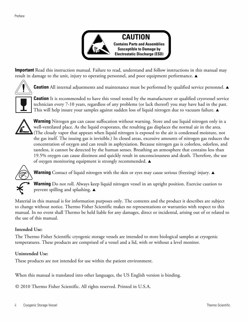
Contains Parts and Assemblies
Susceptible to Damage by
Electrostatic Discharge (ESD)
CAUTION
Important Read this instruction manual. Failure to read, understand and follow instructions in this manual mayresult in damage to the unit, injury to operating personnel, and poor equipment performance. s
Caution All internal adjustments and maintenance must be performed by qualified service personnel. s
Caution It is recommended to have this vessel tested by the manufacturer or qualified cryovessel servicetechnician every 7-10 years, regardless of any problems (or lack thereof) you may have had in the past.This will help insure your samples against sudden loss of liquid nitrogen due to vacuum failure. s
Warning Nitrogen gas can cause suffocation without warning. Store and use liquid nitrogen only in awell-ventilated place. As the liquid evaporates, the resulting gas displaces the normal air in the area.(The cloudy vapor that appears when liquid nitrogen is exposed to the air is condensed moisture, notthe gas itself. The issuing gas is invisible.) In closed areas, excessive amounts of nitrogen gas reduces theconcentration of oxygen and can result in asphyxiation. Because nitrogen gas is colorless, odorless, andtasteless, it cannot be detected by the human senses. Breathing an atmosphere that contains less than19.5% oxygen can cause dizziness and quickly result in unconsciousness and death. Therefore, the useof oxygen monitoring equipment is strongly recommended. s
Warning Contact of liquid nitrogen with the skin or eyes may cause serious (freezing) injury. s
Warning Do not roll. Always keep liquid nitrogen vessel in an upright position. Exercise caution toprevent spilling and splashing. s
Material in this manual is for information purposes only. The contents and the product it describes are subjectto change without notice. Thermo Fisher Scientific makes no representations or warranties with respect to thismanual. In no event shall Thermo be held liable for any damages, direct or incidental, arising out of or related tothe use of this manual.
Intended Use:The Thermo Fisher Scientific cryogenic storage vessels are intended to store biological samples at cryogenictemperatures. These products are comprised of a vessel and a lid, with or without a level monitor.
Unintended Use:These products are not intended for use within the patient environment.
When this manual is translated into other languages, the US English version is binding.
© 2010 Thermo Fisher Scientific. All rights reserved. Printed in U.S.A.
Thermo Scientific Cryogenic Storage Vessel iii
Preface
Important operating and/or maintenance instructions. Read the accompanying text carefully.
Potential electrical hazards. Only qualified persons should perform procedures associated with thissymbol.
Extreme temperature hazards. Only qualified persons should perform procedures associated with thissymbol.
Potential biological hazards. Proper protective equipment and procedures must be used.
Marking of electrical and electronic equipment, which applies to electrical and electronic equipmentfalling under the Directive 2002/96/EC (WEEE) and the equipment that has been put on the marketafter 13 August 2005.
This product is required to comply with the European Union’s Waste Electrical & ElectronicEquipment (WEEE) Directive 2002/96/EC. It is marked with the WEEE symbol. Thermo FisherScientific has contracted with one or more recycling/disposal companies in each EU Member StateEuropean Country, and this product should be disposed of or recycled through them. Furtherinformation on Thermo’s compliance with this directive, the recyclers in your country andinformation on Thermo Scientific products will be available at www.thermoscientific.com.
4 Always use the proper protective equipment (clothing, gloves, goggles, etc.)
4 Always dissipate extreme cold or heat and wear protective clothing.
4 Always follow good hygiene practices.
4 Each individual is responsible for his or her own safety.
Thermo Scientificiv Cryogenic Storage Vessel
Preface
Do You Need Information or Assistance on
Thermo Scientific Products?
If you do, please contact us 8:00 a.m. to 6:00 p.m. (Eastern Time) at:
1-740-373-4763 Direct
1-800-438-4851 Toll Free, U.S. and Canada
1-877-213-8051 FAX
http://www.thermofisher.com Internet Worldwide Web Home Page
[email protected] Tech Support Email Address
Certified Service Web Pagewww.unitylabservices.com
Our staff can provide information on pricing and give you quotations. We canSales Support
take your order and provide delivery information on major equipment items or make
arrangements to have your local sales representative contact you. Our products are listed on the
Internet and we can be contacted through our Internet home page.
Our staff can supply technical information about proper setup, operation orService Support
troubleshooting of your equipment. We can fill your needs for spare or replacement parts or
provide you with on-site service. We can also provide you with a quotation on our Extended
Warranty for your Thermo Scientific products.
Whatever Thermo Scientific products you need or use, we will be happy to discuss your
applications. If you are experiencing technical problems, working together, we will help you
locate the problem and, chances are, correct it yourself...over the telephone without a service
call.
When more extensive service is necessary, we will assist you with direct factory trained
technicians or a qualified service organization for on-the-spot repair. If your service need is
covered by the warranty, we will arrange for the unit to be repaired at our expense and to your
satisfaction.
Regardless of your needs, our professional telephone technicians are available to assist you
Monday through Friday from 8:00 a.m. to 6:00 p.m. Eastern Time. Please contact us by
telephone or fax. If you wish to write, our mailing address is:
Thermo Fisher Scientific (Asheville) LLC
401 Millcreek Road, Box 649
Marietta, OH 45750
International customers, please contact your local Thermo Scientific distributor.
Cryogenic Storage Vessel vThermo Scientific
Table of Contents
Safety Information . . . . . . . . . . . . . . . . . . . . . . . . . . . . . . . . . . . . . . . . . . . . 1-1Please Read . . . . . . . . . . . . . . . . . . . . . . . . . . . . . . . . . . . . . . . . . . . . 1-1General Usage . . . . . . . . . . . . . . . . . . . . . . . . . . . . . . . . . . . . . . . . . . 1-1Warnings . . . . . . . . . . . . . . . . . . . . . . . . . . . . . . . . . . . . . . . . . . . . . . 1-2Cautions . . . . . . . . . . . . . . . . . . . . . . . . . . . . . . . . . . . . . . . . . . . . . . .1-2
General Specifications . . . . . . . . . . . . . . . . . . . . . . . . . . . . . . . . . . . . . . . 2-1Environmental Conditions . . . . . . . . . . . . . . . . . . . . . . . . . . . . . . . . .2-1
Unpacking . . . . . . . . . . . . . . . . . . . . . . . . . . . . . . . . . . . . . . . . . . . . . . . . . . .3-1
Operation . . . . . . . . . . . . . . . . . . . . . . . . . . . . . . . . . . . . . . . . . . . . . . . . . . . .4-1Measuring Liquid Nitrogen Quantity . . . . . . . . . . . . . . . . . . . . . . . . 4-1General Cleaning Instructions . . . . . . . . . . . . . . . . . . . . . . . . . . . . . . 4-2Storing Samples in Vapor Phase . . . . . . . . . . . . . . . . . . . . . . . . . . . . .4-2Cautions . . . . . . . . . . . . . . . . . . . . . . . . . . . . . . . . . . . . . . . . . . . . . . .4-2
Replacement Parts . . . . . . . . . . . . . . . . . . . . . . . . . . . . . . . . . . . . . . . . . . . 5-1
Liquid Nitrogen Level Monitor Operation . . . . . . . . . . . . . . . . . . . . . . . .6-1Installation . . . . . . . . . . . . . . . . . . . . . . . . . . . . . . . . . . . . . . . . . . . . . 6-1Remote Alarm . . . . . . . . . . . . . . . . . . . . . . . . . . . . . . . . . . . . . . . . . . 6-1Alarm Contact Specifications . . . . . . . . . . . . . . . . . . . . . . . . . . . . . . . 6-2Microprocessor Functions . . . . . . . . . . . . . . . . . . . . . . . . . . . . . . . . . 6-4Principles of Operation . . . . . . . . . . . . . . . . . . . . . . . . . . . . . . . . . . . 6-4Level Monitor Operation . . . . . . . . . . . . . . . . . . . . . . . . . . . . . . . . . . 6-5Safety Feature . . . . . . . . . . . . . . . . . . . . . . . . . . . . . . . . . . . . . . . . . . .6-5Audible and Visual Alarms . . . . . . . . . . . . . . . . . . . . . . . . . . . . . . . . .6-5
LN2 Level Monitor Troubleshooting and Parts List . . . . . . . . . . . . . . . 7-1Ordering Procedures . . . . . . . . . . . . . . . . . . . . . . . . . . . . . . . . . . . . . 7-2
Section 1
Section 2
Section 3
Section 4
Section 5
Section 6
Section 7
Cryogenic Storage Vessel 1-1Thermo Scientific
Please Read
Section 1 Safety Information
This manual contains important operating and safety information. Theuser must carefully read and understand the contents of this manual priorto the use of this equipment.
Your Thermo Scientific cryogenic vessel has been designed with function,reliability, and safety in mind. It is the user’s responsibility to install it inconformance with local electrical codes. For safe operation, please payattention to the warnings and cautions throughout the manual.
All cryopreservation vessels, regardless of who manufactures them, use avacuum to provide the super insulative properties needed to keep nitrogenin a liquid form. They are very similar, in fact, to the Thermos® vessels youmay have used to store coffee, soup or milk.
Remember how fragile they were? Since no vacuum is perfect or will lastforever, we suggest that you monitor the consumption of liquid nitrogenused by your vessel on a regular basis, i.e. every 1-2 days. By monitoring,you may be able to anticipate subtle changes in consumption and possiblyreact to problems before they arise. You may opt to use a level monitor forthis purpose (see page 6-1 for level monitor operation.).
Also, if your samples are super critical, one-of-a-kind, or irreplaceable,consider allocating your samples to 2 separate vessels. Remember the oldadage about placing all your eggs into one basket….
Finally, because no vacuum will last forever, have your vessel tested by themanufacturer or a qualified cryovessel service technician every 7-10 years,regardless of any problems (or lack thereof) you may have had in the past.This will help insure your samples against sudden loss of nitrogen due tovacuum failure.
Do not use this product for anything other than its intended usage.
Use of the equipment in a manner not specified by the manufacturer mayimpair the protection provided by the equipment.
General Usage
1-2 Cryogenic Storage Vessel Thermo Scientific
Section 1Safety Information
• This unit is intended to be used by trained personnel in a well-ventilated environment.
• Liquid nitrogen is extremely cold; it boils at -196°C.
• Follow all necessary precautions and warnings relevant to applicablehazards such as frostbite, contact burn, asphyxiation, etc. in cryogenicarea.
• To avoid injury due to frostbite or ruptured vials, use extreme carewhenever handling liquid nitrogen, liquid nitrogen storage or transfervessels, or any objects which have come in contact with liquidnitrogen.
• Leave no areas of skin exposed.
• Wear appropriate PPE where necessary; face shield, cryogenic gloves,cryogenic apron.
• Do not tightly seal liquid nitrogen containers or prevent nitrogen gasfrom escaping.
• Always handle ampules with tongs. They may explode when removedfrom the vessel.
• Use extreme care to prevent spilling and splashing liquid nitrogenduring transfer and removal of storage contents and holders.
• Immediately remove any clothing or safety attire on which liquidnitrogen has been spilled or splashed.
• Get immediate medical attention for any frostbite injuries due toliquid nitrogen.
Warnings
• Only use the power supply provided by the unit.
• Never overfill liquid nitrogen vessels. Liquid nitrogen level shouldnever be above the tops of the racks inside the vessel. The excessweight may crack the neck and result in vacuum failure.
• When inserting or removing racks, be careful not to come in contactwith the neck tube area of the vessel. Remove or insert racks slowlyin a vertical manner. Scratches on the neck tube area can causepremature vacuum failure.
• Do not tamper with or remove vacuum port (covered by a blackplastic cap on side of vessel); this will void warranty.
• Do not spill liquid nitrogen on vacuum port - this can cause vacuumfailure.
• Always keep liquid nitrogen vessel in an upright position.
• Do not use this Locator vessel for transport.
Cryogenic Storage Vessel 1-3Thermo Scientific
Section 1Section title
Cautions
Cryogenic Storage Vessel 2-1Thermo Scientific
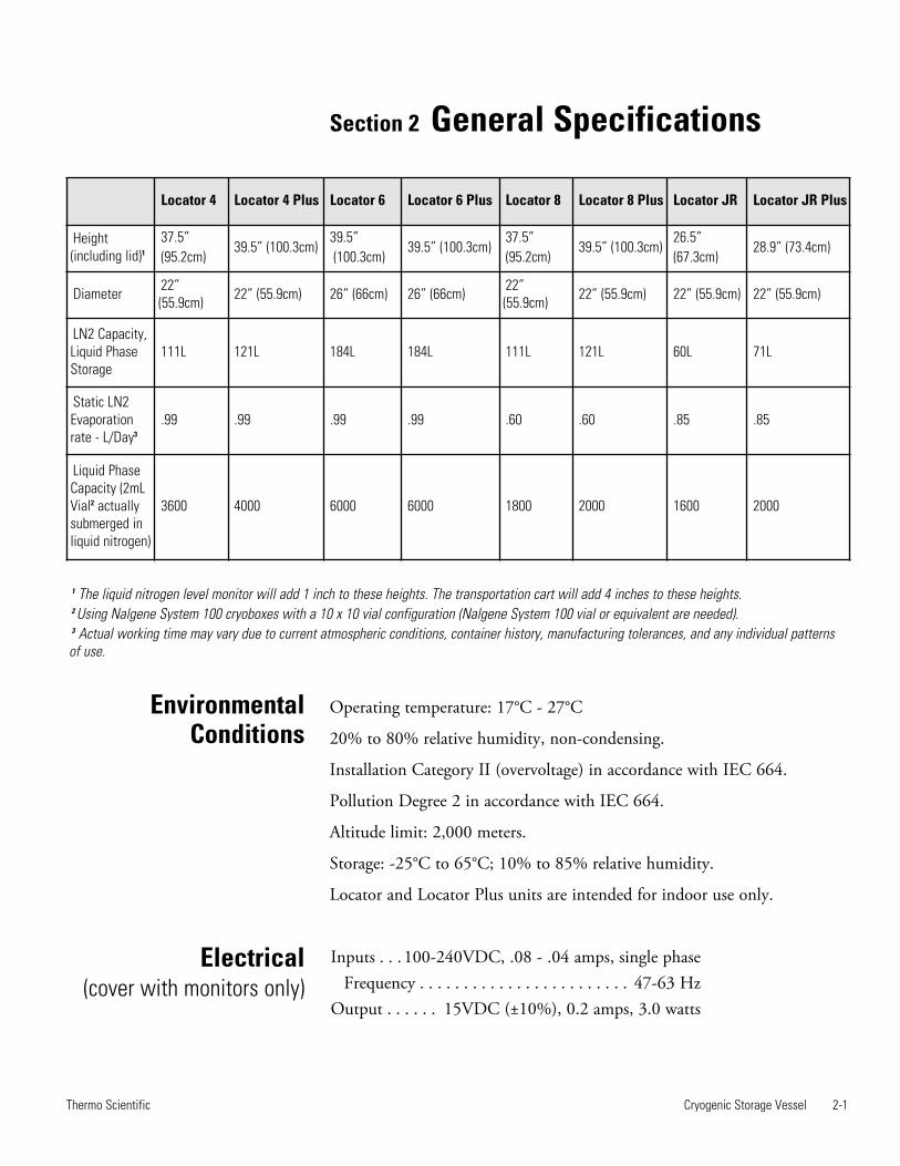
Operating temperature: 17°C - 27°C
20% to 80% relative humidity, non-condensing.
Installation Category II (overvoltage) in accordance with IEC 664.
Pollution Degree 2 in accordance with IEC 664.
Altitude limit: 2,000 meters.
Storage: -25°C to 65°C; 10% to 85% relative humidity.
Locator and Locator Plus units are intended for indoor use only.
Inputs . . . 100-240VDC, .08 - .04 amps, single phaseFrequency . . . . . . . . . . . . . . . . . . . . . . . . 47-63 Hz
Output . . . . . . 15VDC (±10%), 0.2 amps, 3.0 watts
Locator 4 Locator 4 Plus Locator 6 Locator 6 Plus Locator 8 Locator 8 Plus Locator JR Locator JR Plus
Height(including lid)1
37.5” (95.2cm)
39.5” (100.3cm) 39.5”(100.3cm)
39.5” (100.3cm) 37.5” (95.2cm)
39.5” (100.3cm) 26.5” (67.3cm)
28.9” (73.4cm)
Diameter 22”(55.9cm) 22” (55.9cm) 26” (66cm) 26” (66cm) 22”
(55.9cm) 22” (55.9cm) 22” (55.9cm) 22” (55.9cm)
LN2 Capacity,Liquid PhaseStorage
111L 121L 184L 184L 111L 121L 60L 71L
Static LN2Evaporationrate - L/Day3
.99 .99 .99 .99 .60 .60 .85 .85
Liquid PhaseCapacity (2mLVial2 actuallysubmerged inliquid nitrogen)
3600 4000 6000 6000 1800 2000 1600 2000
1 The liquid nitrogen level monitor will add 1 inch to these heights. The transportation cart will add 4 inches to these heights.2 Using Nalgene System 100 cryoboxes with a 10 x 10 vial configuration (Nalgene System 100 vial or equivalent are needed).3 Actual working time may vary due to current atmospheric conditions, container history, manufacturing tolerances, and any individual patternsof use.
EnvironmentalConditions
Electrical (cover with monitors only)
Section 2 General Specifications
Cryogenic Storage Vessel 3-1Thermo Scientific
Section 3 Unpacking
Before using your new Locator or Locator Plus vessel, carefully inspect thevessel prior to use. Check for signs of damage which may have occurred inshipment. It is advisable to fill (see filling instructions) all new units withliquid nitrogen and watch liquid nitrogen loss rate for a few days. If thereare any problems, call Customer Service as soon as possible.
The warranty registration card enclosed with the vessel must be completedand returned to the factory within 30 days to make warranty effective.This information must include the serial number, which is located on thelabel on the vessel.
Note The most prevalent cause of failure of liquid nitrogen storage vesselsis mechanical. The vessel necktube supports the full weight of the innershell and all the liquid nitrogen it contains. A side blow to the vessel causesthe inner shell to swing in a pendulum-like motion causing the necktubeto be damaged. Any storage vessel which has been in an accident, has beendropped, or lowered to hit on its side, will tend to fail more rapidly thanone that has not.
Caution Exercise caution when moving your Locator or Locator Plusvessel. Locator and Locator Plus cryobiological storage systems are nottransportation vessels. Transport carts are designed for mobility within thelab, or lab to lab only. Moving full vessels long distances, over cracks infloor, thresholds, on inclined ramps or in elevators can cause prematurevacuum failure. Avoid using excessive force when moving vessel; this cancause tipping, resulting in damage and/or spilling of liquid nitrogen. s
Note If samples must be transported under cryogenic conditions, considerArctic Express line of Dry Shippers available from Thermo Scientific.
Cryogenic Storage Vessel 4-1Thermo Scientific
Section 4 Operation
Caution Never overfill your Locator or Locator Plus vessel with liquidnitrogen. The liquid nitrogen level in your tank (with racks inserted)should never be above 20 inches (50cm) for Locator 4 and Locator 8, 10inches (25cm) for Locator Jr., 22 inches (55.8cm) for Locator 4, 6, and 8Plus and 12 inches for Locator Jr. Plus. Filling the tank up to or above thebottom of the necktube may cause immediate or premature vacuum failureto occur. s
Caution When inserting or removing racks, be careful not to come incontact with the necktube area of the vessel. Remove or insert racks slowlyin a vertical manner. Scratches on the necktube area can cause prematurevacuum failure. s
Caution Do not spill liquid nitrogen on vacuum port (covered by a blackplastic cap on side of vessel). This can cause vacuum failure. s
To avoid damage to your Locator or Locator Plus cryogenic storage vesselwhich may result in premature vacuum loss, it is important that thefollowing procedure be used when adding liquid nitrogen to a warm vessel.
1. Add only a small amount of liquid nitrogen (5-10 liters) to a new orwarm vessel.
2. Allow this small amount of liquid nitrogen to sit in the covered vesselfor a minimum of 2 hours. This will limit stress caused by the suddentemperature change associated with adding liquid nitrogen to a warmvessel.
3. Add an additional 15 liters of liquid nitrogen to the vessel.
4. Allow vessel to sit for 48 hours and monitor liquid nitrogenconsumption with a wooden yarsdstick, optional dip measurer (part#180143) or Level Monitor.
5. Fill Locator or Locator Plus as indicated (see Caution in this section).Allow for displacement of liquid nitrogen when racks and boxes areinserted.
6. Insert and remove racks slowly. Allow liquid nitrogen to run out ofboxes and off racks.
Filling Instructions
4-2 Cryogenic Storage Vessel Thermo Scientific
Section 4Operation
1. Use a wooden yardstick or optional dip measurer (part #180143) tomeasure liquid nitrogen level. NEVER use a hollow tube or plasticdipstick to measure the liquid nitrogen level.
2. Level will be indicated by the frostline which develops when dipstick isremoved.
3. Level Monitor can be used for constant measurements. See Section 6.
1. Remove the 2 bottom-most cryoboxes from each rack.
2. Measure the height of 2 cryoboxes stacked on top of each other.
3. Fill vessel with liquid nitrogen to the height obtained from Step 2,using a yardstick to measure liquid level in vessel.
4. Place racks into vessel without the 2 bottom-most cryoboxes. Samplesare now above the liquid nitrogen and are stored in the vapor phase.
Important A level monitor should always be used when you store yoursamples in the vapor phase because of the already low levels of liquidnitrogen. Refer to Section 5 for correct level monitor for your system. s
Wipe exterior surfaces with lightly dampened cloth containing mild soapsolution.
Storing Samples inVapor Phase
General CleaningInstructions
Measuring LiquidNitrogen Quantity

Cryogenic Storage Vessel 5-1Thermo Scientific
Section 5 Replacement Parts
Locator and Locator Plus Covers w/o Monitor
Type Standard Covers Covers and Rack Kits (for units withlids made before 3/2010)
Locator Jr. CV509X51 (321746) 1950514
Locator Jr. Plus CV509X51 (321746) 1950515
Locator 4 CV509X51 (321746) 1950516
Locator 4 Plus CV509X51 (321746) 1950517
Locator 6 CV509X50 (321651) 1950513
Locator 6 Plus CV509X50 (321651) 1950513
Locator 8 CV509X23 (317227) CV509X23 (317227)
Locator 8 Plus CV509X23 (317227) CV509X23 (317227)
5-2 Cryogenic Storage Vessel Thermo Scientific
Section 5Replacement Parts
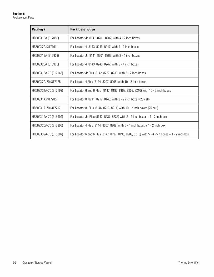
Catalog # Rack Description
HR509X15A (317050) For Locator Jr (8141, 8201, 8202) with 4 - 2 inch boxes
HR509X2A (317161) For Locator 4 (8143, 8246, 8247) with 9 - 2 inch boxes
HR509X19A (315903) For Locator Jr (8141, 8201, 8202) with 2 - 4 inch boxes
HR509X20A (315905) For Locator 4 (8143, 8246, 8247) with 5 - 4 inch boxes
HR509X15A-70 (317148) For Locator Jr Plus (8142, 8237, 8238) with 5 - 2 inch boxes
HR509X2A-70 (317175) For Locator 4 Plus (8144, 8207, 8208) with 10 - 2 inch boxes
HR509X31A-70 (317192) For Locator 6 and 6 Plus (8147, 8197, 8198, 8209, 8210) with 10 - 2 inch boxes
HR509X1A (317205) For Locator 8 (8211, 8212, 8145) with 9 - 2 inch boxes (25 cell)
HR509X1A-70 (317217) For Locator 8 Plus (8146, 8213, 8214) with 10 - 2 inch boxes (25 cell)
HR509X19A-70 (315904) For Locator Jr. Plus (8142, 8237, 8238) with 2 - 4 inch boxes + 1 - 2 inch box
HR509X20A-70 (315906) For Locator 4 Plus (8144, 8207, 8208) with 5 - 4 inch boxes + 1 - 2 inch box
HR509X32A-70 (315907) For Locator 6 and 6 Plus (8147, 8197, 8198, 8209, 8210) with 5 - 4 inch boxes + 1 - 2 inch box
Section 6 Liquid Nitrogen LevelMonitor Operation
The liquid nitrogen (LN2) level monitor provides a constant indication ofthe LN2 level and notifies you to low level conditions through audible andvisual alarms. It alerts you when your vessel needs filling. The levelmonitor is shipped mounted directly to the appropriate Locator or LocatorPlus cover. It can be wired to a remote alarm system to alert you toproblems when you are not in your laboratory. This equipment wasintended to be operated with an external power supply provided by themanufacturer. It is designed for use with Thermo Scientific LN2 vesselsonly.
Caution Use this product for its intended usage only. s
Warning Potential electrical hazards. Only qualified persons shouldperform procedures associated with this symbol. s
Note If the level monitor was purchased as part of a Locator or LocatorPlus system, skip to Step 3. If it is a retrofit for an existing Locator orLocator Plus, begin with Step 1. s
1. Remove the level monitor and Locator or Locator Plus cover from box.
2. Remove present cover from your Locator or Locator Plus and replacewith your new level monitor and cover.
3. Check the electrical specifications on the power supply for electricaldata and plug in to appropriately grounded receptacle.
Cryogenic Storage Vessel 6-1Thermo Scientific
Installation
1. Disconnect the liquid nitrogen level monitor from the power supply.Disconnect power to your alarm system.
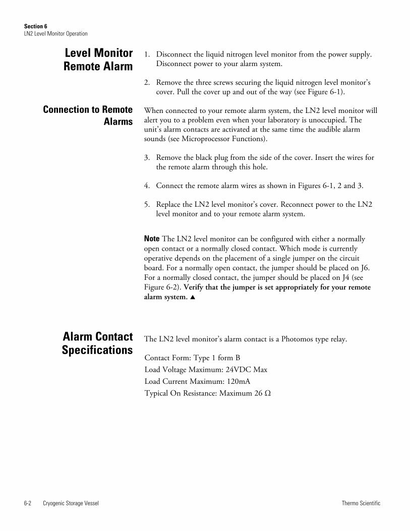
2. Remove the three screws securing the liquid nitrogen level monitor’scover. Pull the cover up and out of the way (see Figure 6-1).
When connected to your remote alarm system, the LN2 level monitor willalert you to a problem even when your laboratory is unoccupied. Theunit’s alarm contacts are activated at the same time the audible alarmsounds (see Microprocessor Functions).
3. Remove the black plug from the side of the cover. Insert the wires forthe remote alarm through this hole.
4. Connect the remote alarm wires as shown in Figures 6-1, 2 and 3.
5. Replace the LN2 level monitor’s cover. Reconnect power to the LN2level monitor and to your remote alarm system.
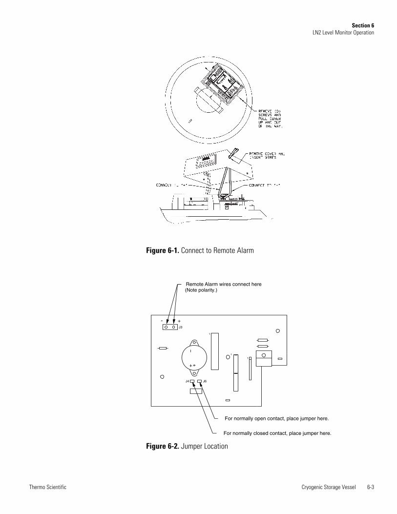
Note The LN2 level monitor can be configured with either a normallyopen contact or a normally closed contact. Which mode is currentlyoperative depends on the placement of a single jumper on the circuitboard. For a normally open contact, the jumper should be placed on J6.For a normally closed contact, the jumper should be placed on J4 (seeFigure 6-2). Verify that the jumper is set appropriately for your remotealarm system. s
The LN2 level monitor’s alarm contact is a Photomos type relay.
Contact Form: Type 1 form BLoad Voltage Maximum: 24VDC Max Load Current Maximum: 120mA Typical On Resistance: Maximum 26 Ω
6-2 Cryogenic Storage Vessel Thermo Scientific
Section 6LN2 Level Monitor Operation
Alarm ContactSpecifications
Level Monitor Remote Alarm
Connection to RemoteAlarms
Cryogenic Storage Vessel 6-3Thermo Scientific
Section 6LN2 Level Monitor Operation
1
1
1
For normally closed contact, place jumper here.
For normally open contact, place jumper here.
Remote Alarm wires connect here (Note polarity.)
- +J3
J4 J6
Figure 6-1. Connect to Remote Alarm
Figure 6-2. Jumper Location
The innovative Thermo LN2 Level Monitor utilises ultrasonic soundwaves to sense the level of liquid nitrogen inside a Locator or Locator Pluscryogenic storage vessel. A microprocessor control provides continuousindication of the liquid nitrogen level inside the Locator or Locator Plus,with accuracy to ±2”. Audible and visual alarms also provide an earlywarning of low level conditions.
Ultrasonic sound waves sense the level of liquid nitrogen inside the Locatoror Locator Plus vessel.
By using ultrasonic sound waves to sense the level of liquid nitrogen, nophysical probe is required to sense the level of liquid nitrogen.Conventional devices use probes which must be in physical contact withthe liquid. This physical contact increases liquid nitrogen consumption.There is NO increase in liquid nitrogen consumption by using theThermo level monitor.
The LED display is graduated in 8 segments and provides quick andreliable visual indication of the level of liquid nitrogen inside the Locatoror Locator Plus vessel, from Full to Empty, similar to a fuel gauge on anautomobile.
6-4 Cryogenic Storage Vessel Thermo Scientific
Section 6LN2 Level Monitor Operation
Principles ofOperation
MicroprocessorFunctions
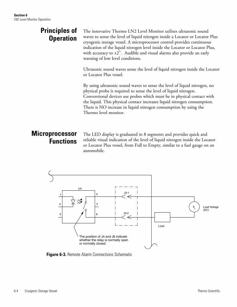
Figure 6-3. Remote Alarm Connections Schematic
1
2
3 6
5
4
Load
J3-2
J3-1
U4
V Load Voltage(DC)
L
The position of J4 and J6 indicatewhether the relay is normally openor normally closed.
1. “LOW LEVEL” indicator light illuminates continuously when liquidnitrogen level is below the approximate 2" level. In this situation, thelevel of liquid nitrogen is low, and you are alerted to refill the vessel assoon as possible.
2. An AUDIBLE and remote alarm activates continuously when liquidnitrogen is below the approximate 1” level inside the Locator orLocator Plus vessel, additionally, “LOW LEVEL” light will continue toflash. In this situation, the liquid nitrogen is dangerously low, and youare alerted to refill the vessel immediately.
3. The AUDIBLE and remote alarms activate continuously, the 8-segment LED display and “Low LEVEL” lights flash, to indicate anemergency event. This alarm event occurs when the Locator or LocatorPlus vessel is empty of liquid nitrogen, or the monitor has an error andis incapable of detecting LN2 levels.
The microprocessor must be reset each time the cover is removed from theLocator or Locator Plus. Before removing the cover, the RESET buttonmust be pressed, illuminating the RESET light. While in this Reset/Holdmode, the monitor is not sensing. After five minutes in the Reset/Holdmode, an audible and remote alarm will activate, alerting you to deactivatethe Reset/Hold mode when the cover is replaced on the vessel.
Once the cover with the monitor has been placed on the vessel andplugged in, wait about 15 minutes for the system to equilibrate beforepressing the Reset button for an accurate measurement of the liquidnitrogen to be indicated. This equilibration process will occur each timethe cover is removed. Each time a vessel is opened or moved, the stabilizedchamber temperature and/or liquid level is disrupted. The system requiresa stable temperature and liquid level to determine an accurate liquidnitrogen level.
If you have just purchased a new Locator or Locator Plus along with yourmonitor, allow at least 1 day for the liquid nitrogen to equilibrate thevessel before plugging in the unit. This will avoid false alarms.
Note The Level Monitor may take up to 10 minutes to establish a readingafter the unit is placed on the cryovessel, or the cryovessel is moved.Remember to press “Reset” after placing unit on the vessel. The greenLED on the switch should be “OFF.” s
Cryogenic Storage Vessel 6-5Thermo Scientific
Section 6LN2 Level Monitor Operation
Audible and VisualAlarms
Safety Feature
Level MonitorOperation
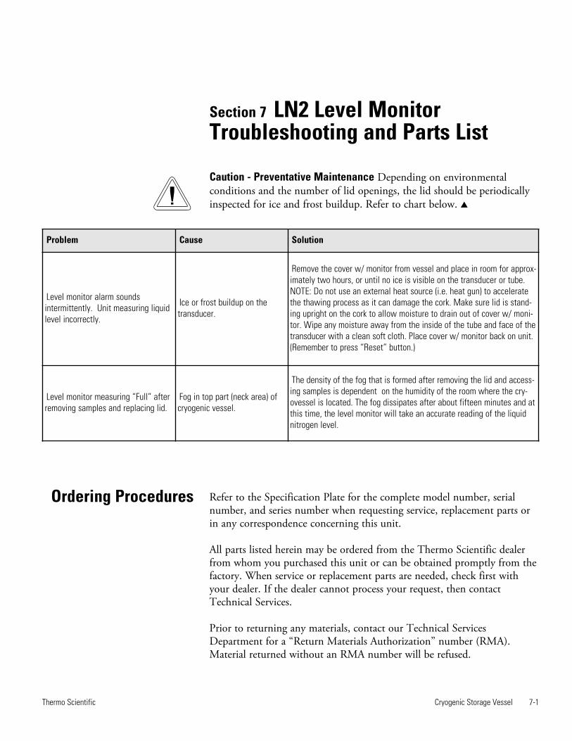
Section 7 LN2 Level MonitorTroubleshooting and Parts List
Cryogenic Storage Vessel 7-1Thermo Scientific
Problem Cause Solution
Level monitor alarm sounds intermittently. Unit measuring liquidlevel incorrectly.
Ice or frost buildup on thetransducer.
Remove the cover w/ monitor from vessel and place in room for approx-imately two hours, or until no ice is visible on the transducer or tube.NOTE: Do not use an external heat source (i.e. heat gun) to acceleratethe thawing process as it can damage the cork. Make sure lid is stand-ing upright on the cork to allow moisture to drain out of cover w/ moni-tor. Wipe any moisture away from the inside of the tube and face of thetransducer with a clean soft cloth. Place cover w/ monitor back on unit.(Remember to press “Reset” button.)
Level monitor measuring “Full” afterremoving samples and replacing lid.
Fog in top part (neck area) ofcryogenic vessel.
The density of the fog that is formed after removing the lid and access-ing samples is dependent on the humidity of the room where the cry-ovessel is located. The fog dissipates after about fifteen minutes and atthis time, the level monitor will take an accurate reading of the liquidnitrogen level.
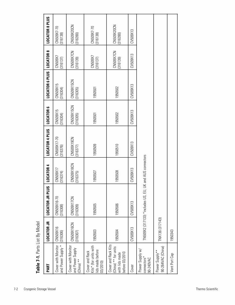
Ordering Procedures Refer to the Specification Plate for the complete model number, serialnumber, and series number when requesting service, replacement parts orin any correspondence concerning this unit.
All parts listed herein may be ordered from the Thermo Scientific dealerfrom whom you purchased this unit or can be obtained promptly from thefactory. When service or replacement parts are needed, check first withyour dealer. If the dealer cannot process your request, then contactTechnical Services.
Prior to returning any materials, contact our Technical ServicesDepartment for a “Return Materials Authorization” number (RMA).Material returned without an RMA number will be refused.
Caution - Preventative Maintenance Depending on environmentalconditions and the number of lid openings, the lid should be periodicallyinspected for ice and frost buildup. Refer to chart below. s
7-2 Cryogenic Storage Vessel Thermo Scientific
PART
LOCA
TOR JR
LOCA
TOR JR PLUS
LOCA
TOR 4
LOCA
TOR 4 PLUS
LOCA
TOR 6
LOCA
TOR 6 PLUS
LOCA
TOR 8
LOCA
TOR 8 PLUS
Cover with Monitor
and Power Supply *CN509X16
(316306)
CN509X16-70
(316308)
CN509X17
(316374)
CN509X17-70
(316376)
CN509X15
(316304)
CN509X15
(316304)
CN509X7
(316137)
CN509X7-70
(316138)
Cover with Monitor
and Power Supply
(China) **
CN509X16CN
(316307)
CN509X17CN
(316309)
CN509X18CN
(316375)
CN509X19CN
(316377)
CN509X15CN
(316305)
CN509X15CN
(316305)
CN509X7CN
(316139)
CN509X20CN
(316390)
Cover and Rack
Kits* (for units with
lids made before
03/2010)
1950503
1950505
1950507
1950509
1950501
1950501
CN509X7
(316137)
CN509X7-70
(316138)
Cover and Rack Kits
(China) ** for units
with lids made
before 03/2010
1950504
1950506
1950508
1950510
1950502
1950502
CN509X7CN
(316139)
CN509X20CN
(316390)
Cover
CV509X13
CV509X13
CV509X13
CV509X13
CV509X13
CV509X13
CV509X13
CV509X13
Power Supply w/
connectors*
90-240VAC
TN509X2 (317133) *includes US, EU, UK and AUS connectors
Power Supply**
90-264VAC (China)TNX136 (317143)
Vent Port Cap
1950343
Table 7-1. Parts List By Model
Cryogenic Storage Vessel 8-1Thermo Scientific
THER
MO
FIS
HER
SC
IEN
TIFI
C S
TAN
DA
RD
PR
OD
UC
T W
AR
RA
NTY
(L
N2
Vacu
um)
The
War
rant
y P
erio
d st
arts
two
wee
ks fr
om th
e da
te y
our
equi
pmen
t is
ship
ped
from
our
faci
lity.
Thi
s al
low
s fo
r sh
ippi
ngtim
e so
the
war
rant
y w
ill g
o in
to e
ffect
at a
ppro
xim
atel
y th
e sa
me
time
your
equ
ipm
ent i
s de
liver
ed. T
he w
arra
nty
prot
ec-
tion
exte
nds
to a
ny s
ubse
quen
t ow
ner d
urin
g th
e fir
st y
ear w
arra
nty
perio
d.
Dur
ing
the
first
yea
r, co
mpo
nent
par
ts p
rove
n to
be
non-
conf
orm
ing
in m
ater
ials
or w
orkm
ansh
ip w
ill b
e re
paire
d or
repl
aced
at T
herm
o's
expe
nse,
labo
r in
clud
ed. L
N2
Vacu
um In
tegr
ity is
cov
ered
for
thre
e ye
ars.
Inst
alla
tion
and
calib
ratio
n ar
e no
tco
vere
d by
this
war
rant
y ag
reem
ent.
The
Tech
nica
l Ser
vice
s D
epar
tmen
t mus
t be
cont
acte
d fo
r war
rant
y de
term
inat
ion
and
dire
ctio
n pr
ior t
o pe
rform
ance
of a
ny re
pairs
. Exp
enda
ble
item
s, g
lass
, filt
ers
and
gask
ets
are
excl
uded
from
this
war
rant
y.
Rep
lace
men
t or
repa
ir of
com
pone
nts
parts
or
equi
pmen
t und
er th
is w
arra
nty
shal
l not
ext
end
the
war
rant
y to
eith
er th
eeq
uipm
ent o
r to
the
com
pone
nt p
art b
eyon
d th
e or
igin
al w
arra
nty
perio
d. T
he T
echn
ical
Ser
vice
s D
epar
tmen
t mus
t giv
e pr
ior
appr
oval
for
ret
urn
of a
ny c
ompo
nent
s or
equ
ipm
ent.
At
Ther
mo'
s op
tion,
all
non-
conf
orm
ing
parts
mus
t be
ret
urne
d to
Ther
mo
post
age
paid
and
repl
acem
ent p
arts
are
shi
pped
FO
B d
estin
atio
n.
THIS
WA
RR
AN
TY I
S EX
CLU
SIVE
AN
D I
N L
IEU
OF
ALL
OTH
ER W
AR
RA
NTI
ES,
WH
ETH
ER W
RIT
TEN
, O
RA
L O
RIM
PLIE
D. N
O W
AR
RA
NTI
ES O
F M
ERC
HA
NTA
BIL
ITY
OR
FIT
NES
S FO
R A
PA
RTI
CU
LAR
PU
RPO
SE S
HA
LL A
PPLY
.Th
erm
o sh
all n
ot b
e lia
ble
for a
ny in
dire
ct o
r con
sequ
entia
l dam
ages
incl
udin
g, w
ithou
t lim
itatio
n, d
amag
es re
latin
g to
lost
prof
its o
r los
s of
pro
duct
s.
Your
loca
l The
rmo
Sal
es O
ffice
is r
eady
to h
elp
with
com
preh
ensi
ve s
ite p
repa
ratio
n in
form
atio
n be
fore
you
r eq
uipm
ent
arriv
es. P
rinte
d in
stru
ctio
n m
anua
ls c
aref
ully
det
ail e
quip
men
t ins
talla
tion,
ope
ratio
n an
d pr
even
tive
mai
nten
ance
.
If eq
uipm
ent s
ervi
ce i
s re
quire
d, p
leas
e ca
ll yo
ur T
echn
ical
Ser
vice
s D
epar
tmen
t at 1
-800
-438
-485
1 (U
SA
and
Can
ada)
or
1-74
0-37
3-47
63.
We'
re r
eady
to
answ
er y
our
ques
tions
on
equi
pmen
t w
arra
nty,
ope
ratio
n, m
aint
enan
ce,
serv
ice
and
spec
ial a
pplic
atio
n. O
utsi
de th
e U
SA
, con
tact
you
r loc
al d
istri
buto
r for
war
rant
y in
form
atio
n.
Rev
. 0 5
/10
ISO
9001
REGI
STER
ED
thermoscientific.com
© 2014 Thermo Fisher Scientific Inc. All rights reserved. All trademarks are the property of Thermo Fisher Scientific and itssubsidiaries. Specifications, termsand pricing are subject to change. Not all products are available in all countries. Please consult your local sales representativefor details.
Thermo Fisher Scientific (Asheville) LLC401 Millcreek RoadMarietta, Ohio 45750
United States
A Thermo Fisher Scientific Brand
LOCATOR® & LOCATOR PlusCryoconservateur biologique
MODE D’EMPLOIET LISTE DES PIECES
TYPE CY50900
Indicateur de niveau d’azote liquideMODE D’EMPLOI
ET LISTE DES PIECESTYPE CE50900
LT509X9T (5018141) 2/23/2016
User M
anual
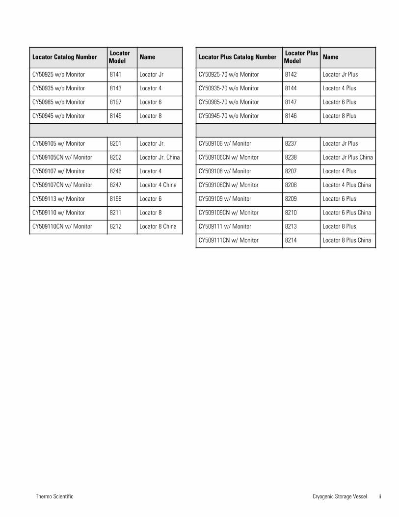
Locator Catalog Number LocatorModel Name
CY50925 w/o Monitor 8141 Locator Jr
CY50935 w/o Monitor 8143 Locator 4
CY50985 w/o Monitor 8197 Locator 6
CY50945 w/o Monitor 8145 Locator 8
CY509105 w/ Monitor 8201 Locator Jr.
CY509105CN w/ Monitor 8202 Locator Jr. China
CY509107 w/ Monitor 8246 Locator 4
CY509107CN w/ Monitor 8247 Locator 4 China
CY509113 w/ Monitor 8198 Locator 6
CY509110 w/ Monitor 8211 Locator 8
CY509110CN w/ Monitor 8212 Locator 8 China
Locator Plus Catalog Number Locator PlusModel Name
CY50925-70 w/o Monitor 8142 Locator Jr Plus
CY50935-70 w/o Monitor 8144 Locator 4 Plus
CY50985-70 w/o Monitor 8147 Locator 6 Plus
CY50945-70 w/o Monitor 8146 Locator 8 Plus
CY509106 w/ Monitor 8237 Locator Jr Plus
CY509106CN w/ Monitor 8238 Locator Jr Plus China
CY509108 w/ Monitor 8207 Locator 4 Plus
CY509108CN w/ Monitor 8208 Locator 4 Plus China
CY509109 w/ Monitor 8209 Locator 6 Plus
CY509109CN w/ Monitor 8210 Locator 6 Plus China
CY509111 w/ Monitor 8213 Locator 8 Plus
CY509111CN w/ Monitor 8214 Locator 8 Plus China
Thermo Scientific Cryogenic Storage Vessel ii
Thermo Scientificiii Cryogenic Storage Vessel
Preface
Contains Parts and Assemblies
Susceptible to Damage by
Electrostatic Discharge (ESD)
CAUTION
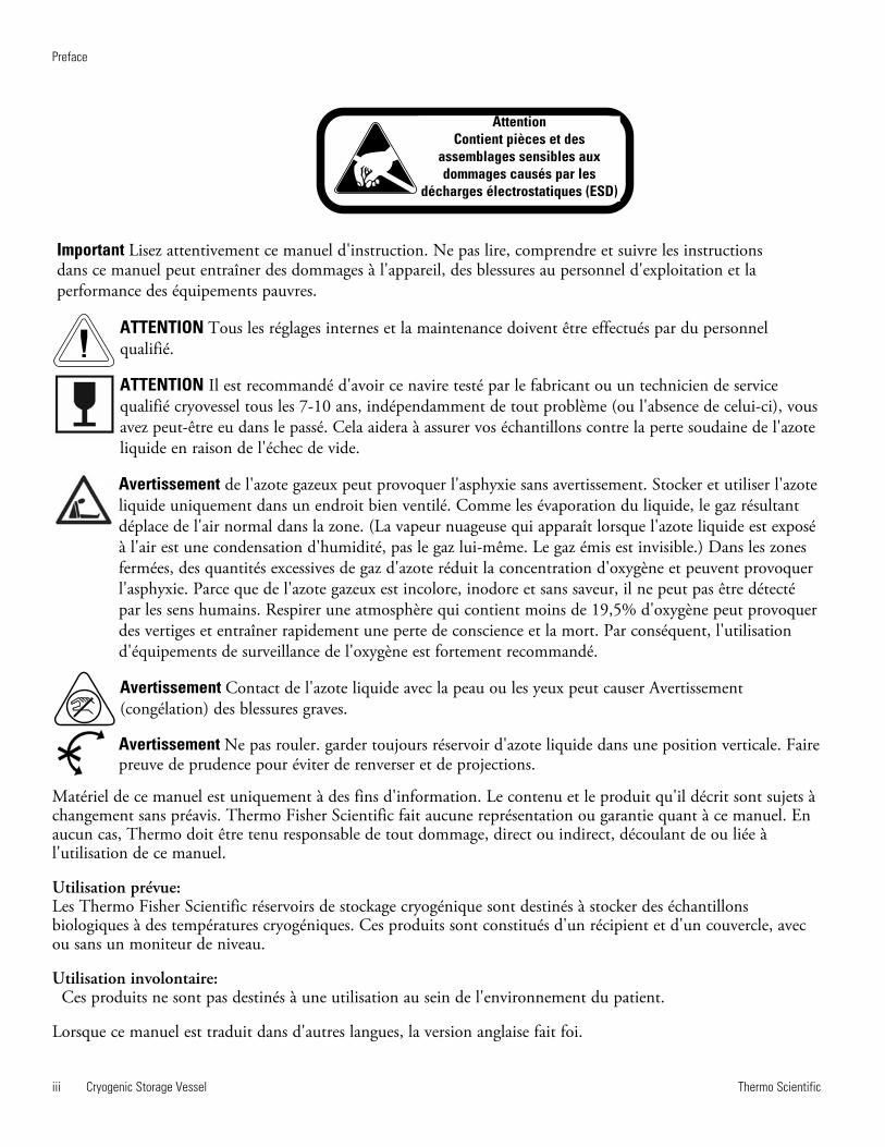
Important Lisez attentivement ce manuel d'instruction. Ne pas lire, comprendre et suivre les instructions dans ce manuel peut entraîner des dommages à l'appareil, des blessures au personnel d'exploitation et la performance des équipements pauvres.
ATTENTION Tous les réglages internes et la maintenance doivent être effectués par du personnelqualifié.
ATTENTION Il est recommandé d'avoir ce navire testé par le fabricant ou un technicien de servicequalifié cryovessel tous les 7-10 ans, indépendamment de tout problème (ou l'absence de celui-ci), vousavez peut-être eu dans le passé. Cela aidera à assurer vos échantillons contre la perte soudaine de l'azoteliquide en raison de l'échec de vide.
Avertissement de l'azote gazeux peut provoquer l'asphyxie sans avertissement. Stocker et utiliser l'azoteliquide uniquement dans un endroit bien ventilé. Comme les évaporation du liquide, le gaz résultantdéplace de l'air normal dans la zone. (La vapeur nuageuse qui apparaît lorsque l'azote liquide est exposéà l'air est une condensation d'humidité, pas le gaz lui-même. Le gaz émis est invisible.) Dans les zonesfermées, des quantités excessives de gaz d'azote réduit la concentration d'oxygène et peuvent provoquerl'asphyxie. Parce que de l'azote gazeux est incolore, inodore et sans saveur, il ne peut pas être détectépar les sens humains. Respirer une atmosphère qui contient moins de 19,5% d'oxygène peut provoquerdes vertiges et entraîner rapidement une perte de conscience et la mort. Par conséquent, l'utilisationd'équipements de surveillance de l'oxygène est fortement recommandé.
Avertissement Contact de l'azote liquide avec la peau ou les yeux peut causer Avertissement(congélation) des blessures graves.
Avertissement Ne pas rouler. garder toujours réservoir d'azote liquide dans une position verticale. Faire preuve de prudence pour éviter de renverser et de projections.
AttentionContient pièces et des
assemblages sensibles auxdommages causés par les
décharges électrostatiques (ESD)
Matériel de ce manuel est uniquement à des fins d'information. Le contenu et le produit qu'il décrit sont sujets àchangement sans préavis. Thermo Fisher Scientific fait aucune représentation ou garantie quant à ce manuel. Enaucun cas, Thermo doit être tenu responsable de tout dommage, direct ou indirect, découlant de ou liée àl'utilisation de ce manuel.
Utilisation prévue:Les Thermo Fisher Scientific réservoirs de stockage cryogénique sont destinés à stocker des échantillonsbiologiques à des températures cryogéniques. Ces produits sont constitués d'un récipient et d'un couvercle, avecou sans un moniteur de niveau.
Utilisation involontaire:Ces produits ne sont pas destinés à une utilisation au sein de l'environnement du patient.
Lorsque ce manuel est traduit dans d'autres langues, la version anglaise fait foi.
Thermo Scientific Cryogenic Storage Vessel iv
Preface
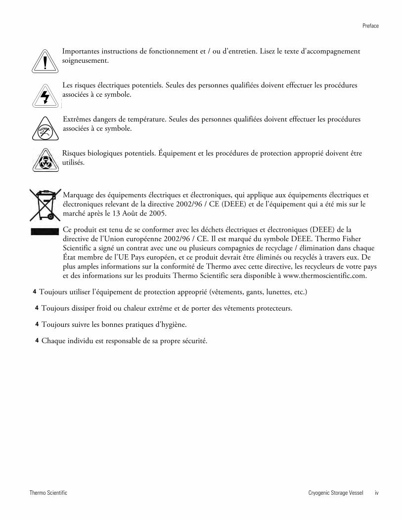
Importantes instructions de fonctionnement et / ou d'entretien. Lisez le texte d'accompagnementsoigneusement.
Les risques électriques potentiels. Seules des personnes qualifiées doivent effectuer les procéduresassociées à ce symbole.
Extrêmes dangers de température. Seules des personnes qualifiées doivent effectuer les procéduresassociées à ce symbole.
Risques biologiques potentiels. Équipement et les procédures de protection approprié doivent êtreutilisés.
Marquage des équipements électriques et électroniques, qui applique aux équipements électriques etélectroniques relevant de la directive 2002/96 / CE (DEEE) et de l'équipement qui a été mis sur lemarché après le 13 Août de 2005.
Ce produit est tenu de se conformer avec les déchets électriques et électroniques (DEEE) de ladirective de l'Union européenne 2002/96 / CE. Il est marqué du symbole DEEE. Thermo FisherScientific a signé un contrat avec une ou plusieurs compagnies de recyclage / élimination dans chaqueÉtat membre de l'UE Pays européen, et ce produit devrait être éliminés ou recyclés à travers eux. Deplus amples informations sur la conformité de Thermo avec cette directive, les recycleurs de votre payset des informations sur les produits Thermo Scientific sera disponible à www.thermoscientific.com.
4 Toujours utiliser l'équipement de protection approprié (vêtements, gants, lunettes, etc.)
4 Toujours dissiper froid ou chaleur extrême et de porter des vêtements protecteurs.
4 Toujours suivre les bonnes pratiques d'hygiène.
4 Chaque individu est responsable de sa propre sécurité.
2
Sommaire
Informations de sécurité......................................................................................................................................3Cartouches d'avertissement ......................................................................................................................3A lire............................................................................................................................................................3Utilisation générale ....................................................................................................................................3
Avertissements....................................................................................................................................................4Caractéristiques générales..................................................................................................................................6
Conditions environnementales ..................................................................................................................6Déclaration de conformité ..........................................................................................................................6
Déballage ............................................................................................................................................................7Fonctionnement ..................................................................................................................................................8
Instructions de remplissage........................................................................................................................8Mesure de la quantité d'azote liquide ........................................................................................................8Stockages d'échantillons dans la phase vapeur ........................................................................................9Instructions générales de nettoyage ..........................................................................................................9
Piéces de rechange du LOCATOR et du LOCATOR Plus ..............................................................................10Accessoires LOCATOR ....................................................................................................................................11Fonctionnement de l'indicateur de niveau d'azote liquide optionnel ................................................................12
Utilisation prévue ......................................................................................................................................12Utilisation générale ..................................................................................................................................12Fonction ....................................................................................................................................................12Procédure d'installation ............................................................................................................................12Alarme á distance de l'indicateur de niveau ............................................................................................12Connexion aux alarmes á distance ..........................................................................................................13Caractéristiques du contact d'alarme de l'indicateur de niveau d'azote liquide ......................................14Principes de fonctionnement ....................................................................................................................15Fonctionnement de l'indicateur de niveau................................................................................................17
Détection des pannes de l'indicateur de niveau d'azote liquide ......................................................................18Garantie ............................................................................................................................................................20
Utilisation prévue: Le Thermo Fisher Scientific vaisseaux de stockage cryogénique sont destinés à conserver les échantillons biologiques à des températures cryogéniques. Ces produits sont composé d'un récipient et un couvercle, avec ou sans moniteur de niveau. Utilisation non conforme: Ces produits ne sont pas destinées à être utilisées dans l'environnement du patient.
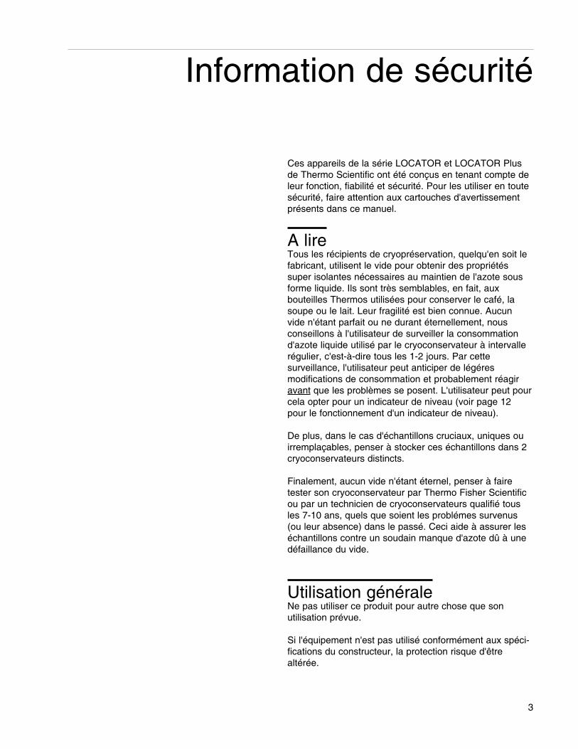
Ces appareils de la série LOCATOR et LOCATOR Plusde Thermo Scientific ont été conçus en tenant compte deleur fonction, fiabilité et sécurité. Pour les utiliser en toutesécurité, faire attention aux cartouches d'avertissementprésents dans ce manuel.
A lireTous les récipients de cryopréservation, quelqu'en soit lefabricant, utilisent le vide pour obtenir des propriétéssuper isolantes nécessaires au maintien de l'azote sousforme liquide. Ils sont très semblables, en fait, auxbouteilles Thermos utilisées pour conserver le café, lasoupe ou le lait. Leur fragilité est bien connue. Aucunvide n'étant parfait ou ne durant éternellement, nous conseillons à l'utilisateur de surveiller la consommationd'azote liquide utilisé par le cryoconservateur à intervallerégulier, c'est-à-dire tous les 1-2 jours. Par cette surveillance, l'utilisateur peut anticiper de légéres modifications de consommation et probablement réagiravant que les problèmes se posent. L'utilisateur peut pourcela opter pour un indicateur de niveau (voir page 12pour le fonctionnement d'un indicateur de niveau).
De plus, dans le cas d'échantillons cruciaux, uniques ouirremplaçables, penser à stocker ces échantillons dans 2cryoconservateurs distincts.
Finalement, aucun vide n'étant éternel, penser à fairetester son cryoconservateur par Thermo Fisher Scientificou par un technicien de cryoconservateurs qualifié tousles 7-10 ans, quels que soient les problémes survenus(ou leur absence) dans le passé. Ceci aide à assurer leséchantillons contre un soudain manque d'azote dû à unedéfaillance du vide.
Utilisation généraleNe pas utiliser ce produit pour autre chose que son utilisation prévue.
Si l'équipement n'est pas utilisé conformément aux spéci-fications du constructeur, la protection risque d'êtrealtérée.
3
Information de sécurité
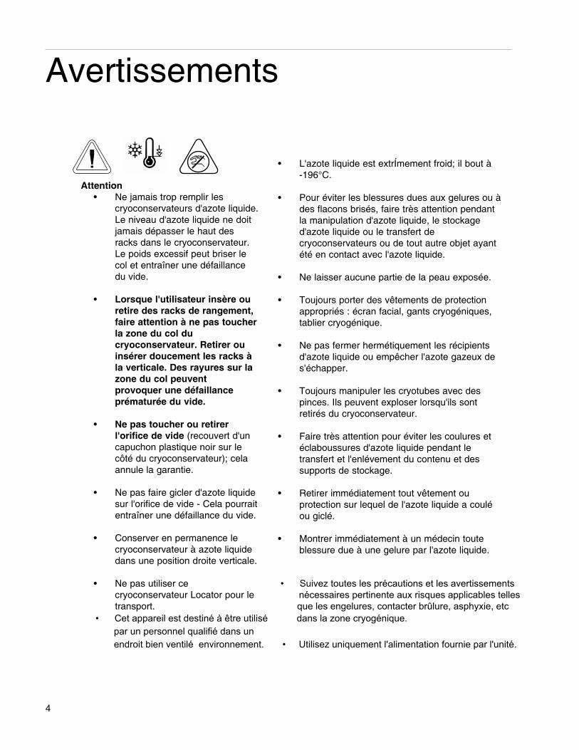
• L'azote liquide est extrÍmement froid; il bout à -196°C.
• Pour éviter les blessures dues aux gelures ou àdes flacons brisés, faire très attention pendantla manipulation d'azote liquide, le stockage d'azote liquide ou le transfert de cryoconservateurs ou de tout autre objet ayantété en contact avec l'azote liquide.
• Ne laisser aucune partie de la peau exposée.
• Toujours porter des vêtements de protectionappropriés : écran facial, gants cryogéniques,tablier cryogénique.
• Ne pas fermer hermétiquement les récipientsd'azote liquide ou empêcher l'azote gazeux des'échapper.
• Toujours manipuler les cryotubes avec despinces. Ils peuvent exploser lorsqu'ils sontretirés du cryoconservateur.
• Faire très attention pour éviter les coulures etéclaboussures d'azote liquide pendant le transfert et l'enlévement du contenu et des supports de stockage.
• Retirer immédiatement tout vêtement ou protection sur lequel de l'azote liquide a couléou giclé.
• Montrer immédiatement à un médecin touteblessure due à une gelure par l'azote liquide.
4
Avertissements
Attention• Ne jamais trop remplir les
cryoconservateurs d'azote liquide.Le niveau d'azote liquide ne doitjamais dépasser le haut desracks dans le cryoconservateur.Le poids excessif peut briser lecol et entraîner une défaillancedu vide.
• Lorsque l'utilisateur insère ouretire des racks de rangement,faire attention à ne pas toucherla zone du col du cryoconservateur. Retirer ouinsérer doucement les racks àla verticale. Des rayures sur lazone du col peuvent provoquer une défaillance prématurée du vide.
• Ne pas toucher ou retirer l'orifice de vide (recouvert d'uncapuchon plastique noir sur lecôté du cryoconservateur); celaannule la garantie.
• Ne pas faire gicler d'azote liquidesur l'orifice de vide - Cela pourraitentraîner une défaillance du vide.
• Conserver en permanence le cryoconservateur à azote liquidedans une position droite verticale.
• Ne pas utiliser ce • Suivez toutes les précautions et les avertissements cryoconservateur Locator pour le nécessaires pertinente aux risques applicables telles transport. que les engelures, contacter brûlure, asphyxie, etc
• Cet appareil est destiné à être utilisé dans la zone cryogénique. par un personnel qualifié dans un endroit bien ventilé environnement. • Utilisez uniquement l'alimentation fournie par l'unité.
5
Caractéristiques générales
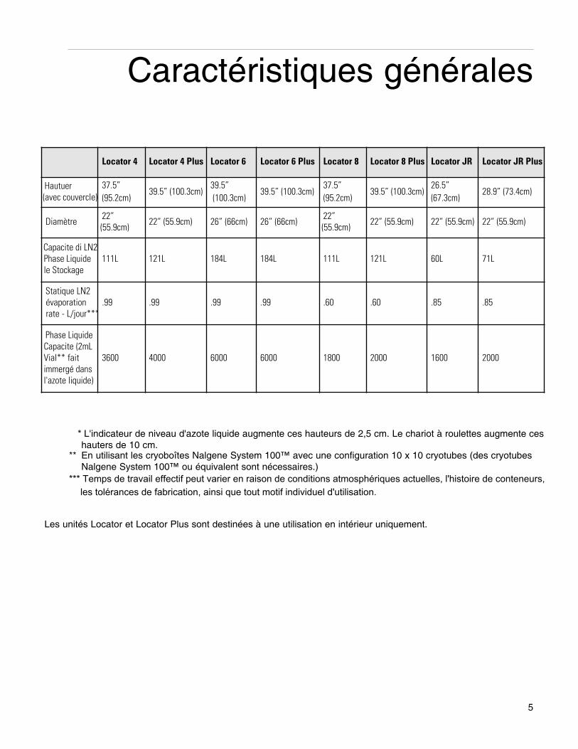
* L'indicateur de niveau d'azote liquide augmente ces hauteurs de 2,5 cm. Le chariot à roulettes augmente ceshauters de 10 cm.
** En utilisant les cryoboîtes Nalgene System 100™ avec une configuration 10 x 10 cryotubes (des cryotubesNalgene System 100™ ou équivalent sont nécessaires.)
*** Temps de travail effectif peut varier en raison de conditions atmosphériques actuelles, l'histoire de conteneurs, les tolérances de fabrication, ainsi que tout motif individuel d'utilisation.
Les unités Locator et Locator Plus sont destinées à une utilisation en intérieur uniquement.
Locator 4 Locator 4 Plus Locator 6 Locator 6 Plus Locator 8 Locator 8 Plus Locator JR Locator JR Plus
Hautuer(avec couvercle)
37.5” (95.2cm)
39.5” (100.3cm) 39.5”(100.3cm)
39.5” (100.3cm) 37.5” (95.2cm)
39.5” (100.3cm) 26.5” (67.3cm)
28.9” (73.4cm)
Diamètre 22”(55.9cm) 22” (55.9cm) 26” (66cm) 26” (66cm) 22”
(55.9cm) 22” (55.9cm) 22” (55.9cm) 22” (55.9cm)
Capacite di LN2 Phase Liquide le Stockage
111L 121L 184L 184L 111L 121L 60L 71L
Statique LN2 évaporation rate - L/jour***
.99 .99 .99 .99 .60 .60 .85 .85
Phase LiquideCapacite (2mLVial** faitimmergé dans l'azote liquide)
3600 4000 6000 6000 1800 2000 1600 2000
Conditions environnementalesFonctionnement: 17°C - 27°C; 20% à 80% d'humiditè relative, sans condensation. Catégorie
d'Installation II (surtension) conformément à IEC 664. Degré de Pollution 2 conformément à IEC 664.
Altitude maximale: 2000 mètres.
Rangement: -25°C à 65°C; 10% à 85% d'humiditè relative.
6
CARACTÉRISTIQUES GÉNÉRALES
électrique (couvrir avec des moniteurs)
Entrées . . .100-240VDC, .08 - .04 amps, single phase
Fréquence . . . . . . . . . . . . . . . . . . . . . . . .47-63 Hz
Sortie . . . . . .15VDC (±10%), 0.2 amps, 3.0 watts
Avant d'utiliser un nouveau cryoconservateur LOCATORou LOCATOR Plus, inspecter soigneusement le cryoconservateur avant utilisation. Véérifier l'absence designe de dommage pouvant s'être produit pendant letransport. Nous conseillons de remplir (voir Instructionsde remplissage) tous les nouveaux appareils avec de l'azote liquide et d'observer le taux de perte d'azote liquide pendant quelques jours. En cas de problème,appeler THERMO FISHER SCIENTIFIC dès que possible.
7
Déballage
AttentionFaire attention en déplaçant le cryoconservateur LOCATOR ou LOCA-TOR PLUS. Les systèmes de conservation cryobiologique LOCATOR et LOCATORPlus ne sont pas des cryoconservateurstransportables. Le support à roulettes estconçu pour assurer uniquement undéplacement dans le laboratoire ou d'unlaboratoire à un autre. Le déplacement decryoconservateurs pleins sur de longuesdistances, sur un sol irrégulier, des seuils,sur des plans inclinés ou des ascenseurspeut entraîner une défaillance prématurée du vide.
RemarqueLa cause la plus fréquente de défaillance des cryoconservateurs àazote liquide est mécanique. Le tube ducol du cryoconservateur supporte tout lepoids de la coque interne et de l'azoteliquide qu'elle contient. Un choc latéralsur le cryoconservateur entraîne un balancement de la coque interne etendommage de ce fait le tube du col.Tout cryoconservateur ayant subi unaccident, qui est tombé ou qui a heurtéle sol sur le côté aura tendance à durermoins longtemps qu'un autre.
Evite el uso excesivo de la fuerza al moverbuque; esto puede causar vuelco, lo que resultaen daños y / o derrame de nitrógeno líquido.
Instructions de remplissagePour èviter d'endommager le cryoconservateur LOCATOR ou LOCATOR Plus et d'entraîner une perte devide prématurée, il est important de respecter la procédure suivante pour ajouter de l'azote liquide à un cryoconservateur chaud:
1. Ajouter uniquement une petite quantité d'azoteliquide (5-10 litres) dans un cryoconservateurneuf ou chaud.
2. Laisser cette petite quantité d'azote liquidereposer dans le cryoconservateur fermé pendant au minimum 2 heures. Ceci limitera latension causée par le brusque changement detempérature consécutif à l'addition d'azote liquide dans un cryoconservateur chaud.
3. Ajouter 15 litres d'azote liquide supplémentairesdans ce cryoconservateur.
4. Laisser reposer le cryoconservateur pendant 48heures et surveiller la consommation d'azote liquide avec un mètre pliant en bois ou avecl'indicateur de niveau.
5. Remplir le LOCATOR ou le LOCATOR Pluscomme indiqué (voir Attention). Se rappeler depermettre à l'azote liquide de se déplacerlorsque des racks et des boîtes sont insérés.
6. Insérer et retirer les racks lentement. Laisser l'azote liquide s'écouler hors des boîtes et desracks.
Mesure de la quantité d'azoteliquide
1. Utiliser un mètre pliant en bois pour mesurer leniveau d'azote liquide. NE JAMAIS utiliser detube creux ou de tige en plastique pour mesurerle niveau d'azote liquide.
8
Fonctionnement
Attention• Ne jamais trop remplir les cryoconservateurs LOCATOR ou LOCATOR Plus avec de l'azote liquide.Le niveau d'azote liquide dans le réservoir (avec les racks insérés) ne doitjamais dépasser 50 cm pour LOCATOR 4 et LOCATOR 8, 25 cmpour LOCATOR Jr., 55,8 cm pourLOCATOR 4, 6 et 8 Plus et 12cm pour LOCATOR Jr. Plus. Le remplis-sage du réservoir jusqu'au-dessus dubas du tube du col entraîne une défail-lance du vide immédiate ou prématurée.
• Lorsque l'utilisateur insère ou retiredes racks de rangement, faire attentionà ne pas toucher la zone du col du cryoconservateur. Retirer ou insérerdoucement les racks à la verticale. Desrayures sur la zone du col peuventprovoquer une défaillance prématuréedu vide.
• Ne pas faire gicler d'azote liquide surl'orifice de vide (recouvert d'un capuchon plastique noir sur le côté ducryoconservateur). Cela pourrait entraîner une défaillance du vide.
2. Le niveau est indiqué par la ligne de givre qui sedéveloppe lorsque le mètre pliant est retiré.
3. L'indicateur de niveau peut être utilisé pour desmesures en continu. Voir page 14.
Stockage d'échantillons dans laphase vapeur
1. Retirer les 2 cryoboîtes les plus basses dechaque rack.
2. Mesurer la hauteur des 2 cryoboîtes empiléesl'une sur l'autre.
3. Remplir le cryoconservateur d'azote liquidejusqu'à la hauteur obtenue à l'étape 2 en utilisant un mètre pliant en bois pour mesurer leniveau de liquide dans le cryoconservateur.
4. Placer les racks dans le cryoconservateur sansles deux cryoboîtes les plus basses.
– Les échantillons sont maintenant au-dessus de l'azoteliquide et sont conservés dans la phase vapeur.–
Important – Il convient de toujours utiliser un indicateurde niveau pour stocker ses échantillons dans la phasevapeur à cause du niveau déjà bas de l'azote liquide. Sereporter à la page 10 pour l'indicateur de niveau correctcorrespondant à son systéme.
Instructions générales de nettoyageEssuyer les surfaces extérieures avec un chiffon légèrement humide contenant une solution de savondoux.
9
FONCTIONNEMENT
10
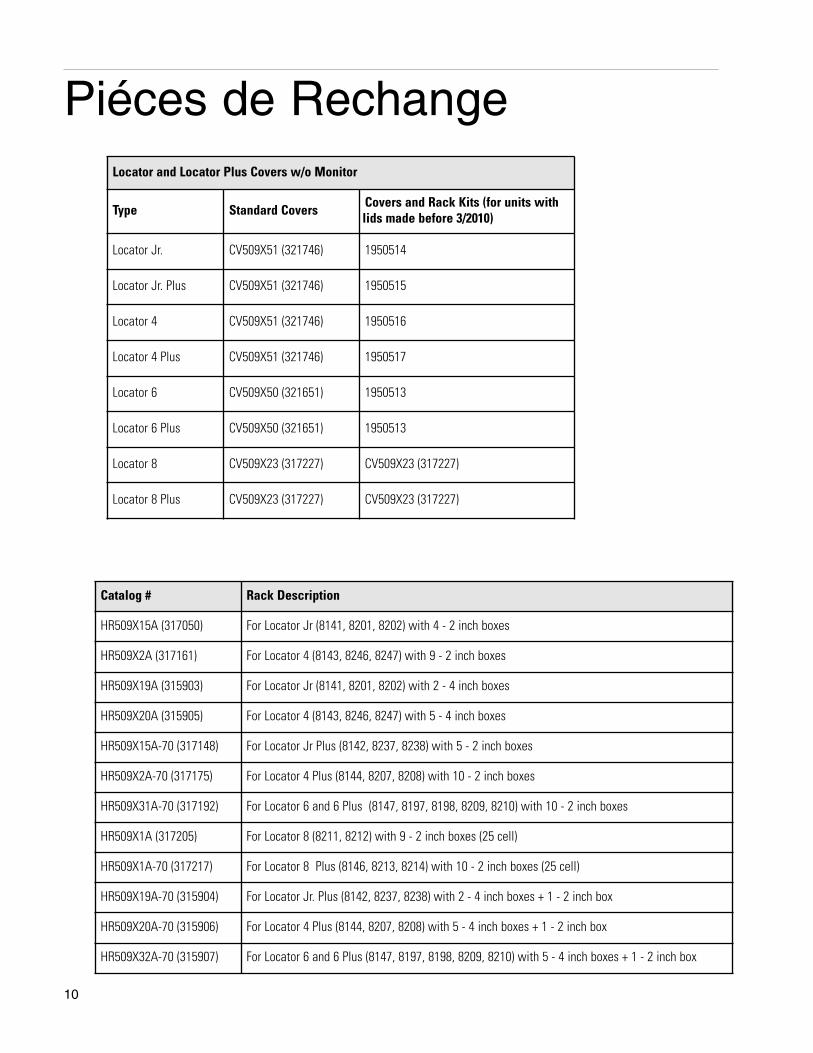
Piéces de Rechange
Catalog # Rack Description
HR509X15A (317050) For Locator Jr (8141, 8201, 8202) with 4 - 2 inch boxes
HR509X2A (317161) For Locator 4 (8143, 8246, 8247) with 9 - 2 inch boxes
HR509X19A (315903) For Locator Jr (8141, 8201, 8202) with 2 - 4 inch boxes
HR509X20A (315905) For Locator 4 (8143, 8246, 8247) with 5 - 4 inch boxes
HR509X15A-70 (317148) For Locator Jr Plus (8142, 8237, 8238) with 5 - 2 inch boxes
HR509X2A-70 (317175) For Locator 4 Plus (8144, 8207, 8208) with 10 - 2 inch boxes
HR509X31A-70 (317192) For Locator 6 and 6 Plus (8147, 8197, 8198, 8209, 8210) with 10 - 2 inch boxes
HR509X1A (317205) For Locator 8 (8211, 8212) with 9 - 2 inch boxes (25 cell)
HR509X1A-70 (317217) For Locator 8 Plus (8146, 8213, 8214) with 10 - 2 inch boxes (25 cell)
HR509X19A-70 (315904) For Locator Jr. Plus (8142, 8237, 8238) with 2 - 4 inch boxes + 1 - 2 inch box
HR509X20A-70 (315906) For Locator 4 Plus (8144, 8207, 8208) with 5 - 4 inch boxes + 1 - 2 inch box
HR509X32A-70 (315907) For Locator 6 and 6 Plus (8147, 8197, 8198, 8209, 8210) with 5 - 4 inch boxes + 1 - 2 inch box
Locator and Locator Plus Covers w/o Monitor
Type Standard Covers Covers and Rack Kits (for units withlids made before 3/2010)
Locator Jr. CV509X51 (321746) 1950514
Locator Jr. Plus CV509X51 (321746) 1950515
Locator 4 CV509X51 (321746) 1950516
Locator 4 Plus CV509X51 (321746) 1950517
Locator 6 CV509X50 (321651) 1950513
Locator 6 Plus CV509X50 (321651) 1950513
Locator 8 CV509X23 (317227) CV509X23 (317227)
Locator 8 Plus CV509X23 (317227) CV509X23 (317227)
11
Utilisation prévueDonne une indication constante du niveau d'azote liquideet alerte l'utilisateur en cas de niveau insuffisant par l'intermédiaire d'une alarme sonore et visuelle.L'indicateur de niveau d'azote liquide optionnel peut êtreconnecté à un systéme d'alarme à distance pour alerterl'utilisateur en cas de problème lorsqu'il n'est pas dansson laboratoire.
Utilisation généraleNe pas utiliser ce produit pour autre chose que son utilisation prévue.
FonctionSauvegarde les échantillons précieux en informant l'utilisateur lorsque le cryoconservateur nécessite un remplissage et en l'alertant en cas de perte excessived'azote liquide.
Procédure d'installation1. Retirer l'indicateur de niveau et le couvercle du
LOCATOR ou LOCATOR Plus de la boîte.
2. Retirer le couvercle actuel du LOCATOR ouLOCATOR Plus et le remplacer par les nouveaux indicateurs de niveau et couvercle.
3. Vérifier les caractéristiques de l'alimentationélectrique et brancher dans une prise correctement reliée à la terre.
Alarme à distance de l'indicateur de niveau
1. Déconnecter l'indicateur de niveau d'azote liquide de l'alimentation électrique. Déconnecterle courant du système d'alarme.
Fonctionnement de l'indicateur deniveau d'azote liquide optionnel
RemarqueSi l'indicateur de niveau a étéacheté avec un système LOCATORou LOCATOR Plus, passer à l'étape3. Si l'indicateur a été rajouté plustard sur un LOCATOR ou un LOCATOR Plus existant, commencer à l'étape 1.
Remarque L'indicateur de niveau est expédiédirectement monté sur le couvercledu LOCATOR ou LOCATOR Plusapproprié.
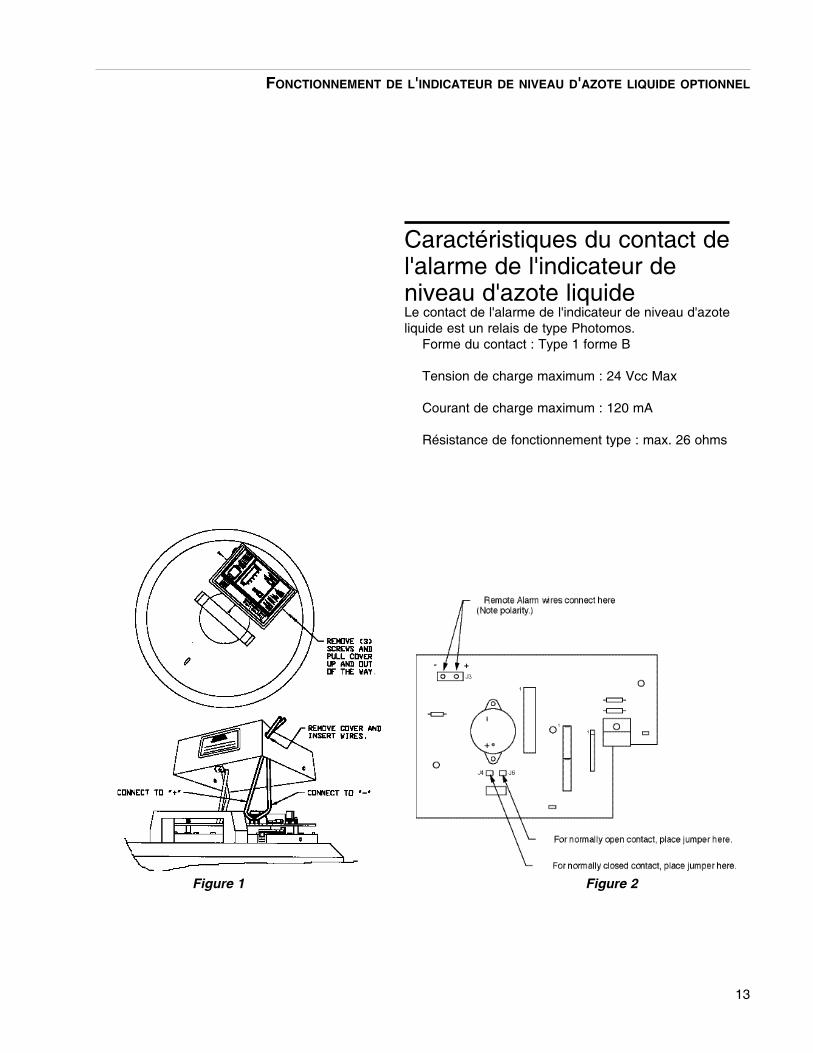
2. Retirer les trois vis maintenant le couvercle del'indicateur de niveau d'azote liquide. Tirer etsoulever le couvercle et le mettre de côté (voirfigure 1).
Connexion aux alarmes à distanceLorsqu'il est connecté au système d'alarme à distance,l'indicateur de niveau d'azote liquide alerte l'utilisateur encas de problème même lorsque le laboratoire est inoccupé. Les contacts de l'alarme de l'indicateur deniveau d'azote liquide sont activés en même temps quel'alarme sonore retentit (voir Fonctions du microprocesseur).
3. Retirer le bouchon noir du côté du couvercle.Insérer les câbles pour l'alarme à distance à travers ce trou.
4. Connecter les câbles de l'alarme à distancecomme montré sur les figures 1, 2 et 3.
5. Remette en place le couvercle de l'indicateur deniveau d'azote liquide. Restaurer l'alimentationélectrique de l'indicateur de niveau d'azote liquide et du système d'alarme à distance.
12
Remarque L'indicateur de niveau d'azote liquidepeut être configuré pour présenter lesystème d'alarme de l'utilisateuravec un contact normalement ouvertou fermé. Le mode en cours utilisédépend de la position d'une seulejonction sur la carte de circuitimprimé. Pour un contact normalement ouvert, la jonction doitêtre placée sur J4 (voir figure 1).Vérifier que la jonction est correctement réglée en fonctiondu système d'alarme à distance.
RemarqueL'équipement est conçu pour fonction-ner à l'aide d'une alimentation externefournie par le fabricant.
RemarqueL'écran de contrôle de niveau estconçu pour être ulitisé avec les fla-cons d'azote liquide de ThermoScientific UNIQUEMENT.
FONCTIONNEMENT DE L'INDICATEUR DE NIVEAU D'AZOTE LIQUIDE OPTIONNEL
13
FONCTIONNEMENT DE L'INDICATEUR DE NIVEAU D'AZOTE LIQUIDE OPTIONNEL
Caractéristiques du contact del'alarme de l'indicateur deniveau d'azote liquideLe contact de l'alarme de l'indicateur de niveau d'azoteliquide est un relais de type Photomos.
Forme du contact : Type 1 forme B
Tension de charge maximum : 24 Vcc Max
Courant de charge maximum : 120 mA
Résistance de fonctionnement type : max. 26 ohms
Figure 1 Figure 2
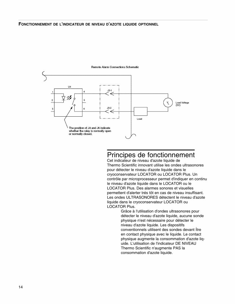
Principes de fonctionnementCet indicateur de niveau d'azote liquide de Thermo Scientific innovant utilise les ondes ultrasonorespour détecter le niveau d'azote liquide dans le cryoconservateur LOCATOR ou LOCATOR Plus. Un contrôle par microprocesseur permet d'indiquer en continule niveau d'azote liquide dans le LOCATOR ou le LOCATOR Plus. Des alarmes sonores et visuelles permettent d'alerter trés tôt en cas de niveau insuffisant.Les ondes ULTRASONORES détectent le niveau d'azoteliquide dans le cryoconservateur LOCATOR ou LOCATOR Plus.
Grâce à l'utilisation d'ondes ultrasonores pourdétecter le niveau d'azote liquide, aucune sondephysique n'est nécessaire pour détecter leniveau d'azote liquide. Les dispositifs conventionnels utilisent des sondes devant Ítreen contact physique avec le liquide. Le contactphysique augmente la consommation d'azote liq-uide. L'utilisation de l'indicateur DE NIVEAUThermo Scientific n'augmente PAS la consommation d'azote liquide.
14
FONCTIONNEMENT DE L'INDICATEUR DE NIVEAU D'AZOTE LIQUIDE OPTIONNEL
15
FONCTIONNEMENT DE L'INDICATEUR DE NIVEAU D'AZOTE LIQUIDE OPTIONNEL
Fonctions du microprocesseurIndication LED à 8 segments du niveau d'azote liquide.
L'affichage LED est gradué par 8 segments;Plein de Vide, de la mÍme façon qu'une jauge àessence sur une voiture. L'affichage LED donneune indication visuelle rapide et fiable du niveau d'azote liquide dans le cryoconservateur LOCATOR ou LOCATOR Plus.
Alarmes sonores et visuelles:
1. "Low Level" voyant lumineux s'allumeen permanence lorsque le liquideteneur en azote est inférieure à laapproximative 2 "niveau. Dans cettesituation, le niveau de l'azote liquide estfaible, et vous êtes alerté à remplir lacuve que dès que possible.
2. Une alarme sonore et à distance activeen permanence lorsque le liquided'azote est inférieure à la approximatifde 1 "à l'intérieur du niveau delocalisation ou Locator Plus navire, enoutre, "Low Level" lumière continuera àflash. Dans cette situation, l'azoteliquide est dangereusement bas, et voussont alertés de remplir la cuveimmédiatement.
3. 3. Les alarmes sonores et à distance activer en permanence, la 8 - segments à LED et "Low Level" lampes de poche, pour indiquer une d'urgence événement. Cet événement d'alarme se produit lorsque le Locator ou Locator Plus navire est vide d'azote liquide, ou le moniteur a und'erreur et est incapable de détecter des niveaux LN2.
16
Fonctionnement de l'indicateurde niveauLorsque le couvercle avec l'indicateur a été plac´ sur lecryoconservateur et branché, le syst´ème met 15 minutesà s'équilibrer avant d'indiquer une mesure précise duniveau d'azote liquide. Le processus d'équilibre se met enroute chaque fois que le cryoconservateur est utilisé.Chaque fois que le cryoconservateur est ouvert, la stabilité de la température de la cuve est rompue. Le système a besoin d'une température stable pour déterminer avec précision le niveau d'azote liquide.
Si un nouveau LOCATOR ou LOCATOR Plus a étéacheté en mÍme temps que l'indicateur, laisser l'azote liquide s'équilibrer pendant au moins 1 jour avant debrancher l'appareil. Ceci évitera de fausses alertes.
FONCTIONNEMENT DE L'INDICATEUR DE NIVEAU D'AZOTE LIQUIDE OPTIONNEL
Remarque L'indicateur de niveau peut mettre10 minutes pour effectuer une lecture après avoir placé l'appareilsur le cryoconservateur. Se rappelerd'appuyer sur la touche "Reset"(restauration) après avoir mis l'appareil sur le cryoconservateur. LaLED verte sur le commutateur doitêtre "OFF" (arrêt).
Le microprocesseur doit être réinitialisé à chaque fois que le couvercle est retiré de la Plus Locator ou Locator. Avant de retirer le couvercle, le bouton RESET doit être enfoncé, la lumière éclairante RESET. Bien que dans ce Reset / Hold mode, le moniteur n'est pas de détection. Après cinq minutes dans le Reset / Hold mode, une alarme sonore et à distance pour activer, de désactiver l'alerte vous la remise en marche / mode Hold et replacez le couvercle sur le navire.
17
Détection des pannes de l'indicateurde niveau d'azote liquide
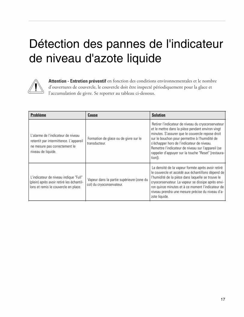
Problème Cause Solution
L'alarme de l'indicateur de niveauretentit par intermittence. L'appareilne mesure pas correctement le niveau de liquide.
Formation de glace ou de givre sur letransducteur.
Retirer l'indicateur de niveau du cryoconservateuret le mettre dans la pièce pendant environ vingtminutes. S'assurer que le couvercle repose droitsur le bouchon pour permettre à l'humidité des'échapper hors de l'indicateur de niveau. Remettre l'indicateur de niveau sur l'appareil (serappeler d'appuyer sur la touche "Reset" [restaura-tion]).
L'indicateur de niveau indique "Full"(plein) après avoir retiré les échantil-lons et remis le couvercle en place.
Vapeur dans la partie supérieure (zone ducol) du cryoconservateur.
La densité de la vapeur formée après avoir retiréle couvercle et accédé aux échantillons dépend del'humidité de la pièce dans laquelle se trouve lecryoconservateur. La vapeur se dissipe après envi-ron quinze minutes et à ce moment l'indicateur deniveau prendra une mesure précise du niveau d'a-zote liquide.
Attention - Entretien préventif en fonction des conditions environnementales et le nombre d'ouvertures de couvercle, le couvercle doit être inspecté périodiquement pour la glace et l'accumulation de givre. Se reporter au tableau ci-dessous.
18
Procédures de commandeReportez-vous à la plaque signalétique pour le numérode modèle complet, le numéro de série et le numéro desérie lors de la demande de service, le remplacementpièces ou de toute correspondance relative à cette unité.Toutes les pièces énumérées dans ce document peuventêtre commandées auprès du concessionnaire ThermoScientific.Partir duquel vous avez acheté cet appareil ou peuventêtre obtenus rapidement de la usine. Lorsque des piècesde réparation ou de remplacement sont nécessaires, véri-fiez d'abord avec votre revendeur. Si le concessionnairene peut pas traiter votre demande, contactezServices techniques.Avant de retourner tout matériel, s'il vous plaît contacternotre Service Technique Département pour un retour dematériel "autorisation" numéro (RMA).Tout articleretourné sans numéro RMA sera refusé.
DÉTECTION DES PANNES DE L'INDICATEUR DE NIVEAU D'AZOTE LIQUIDE
19
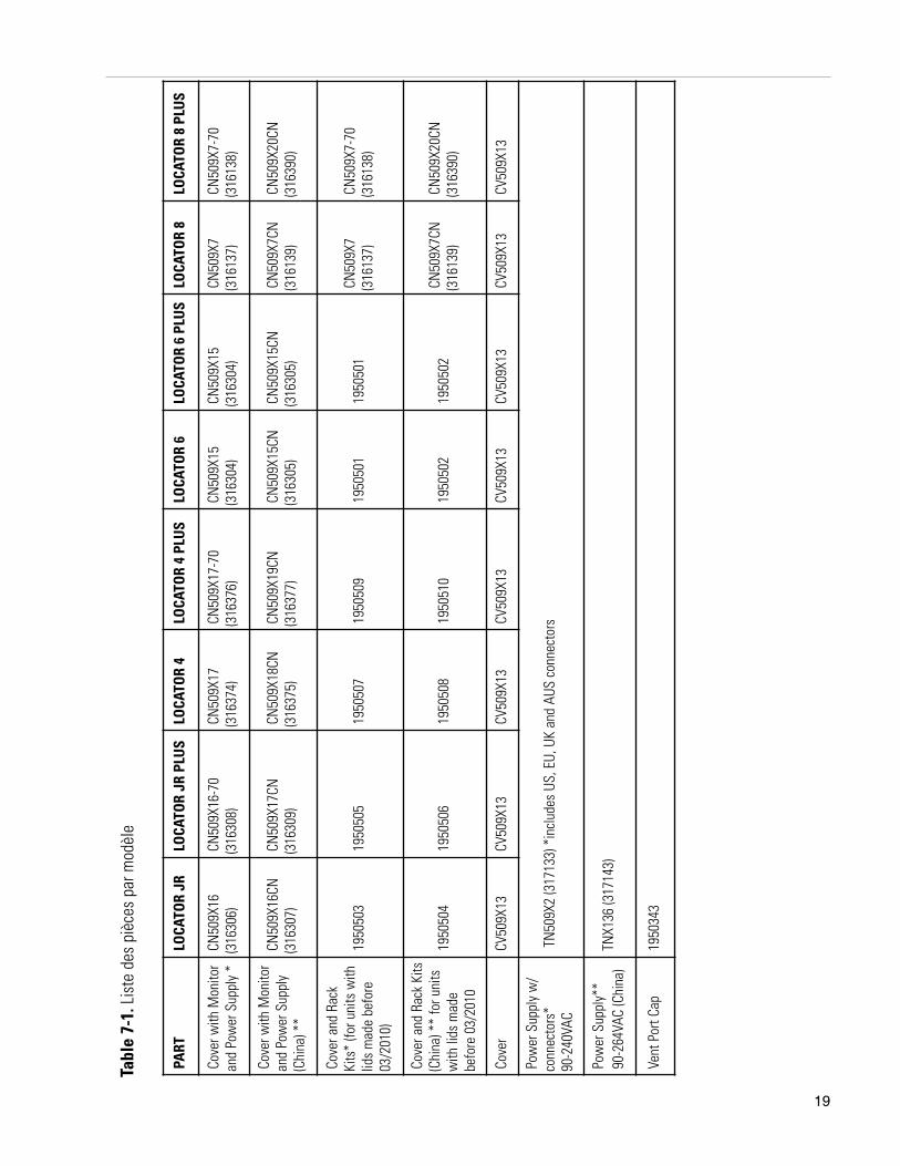
Tabl
e 7-
1. L
iste
des
piè
ces
par m
odèl
e
PART
LO
CATO
R JR
LOCA
TOR
JR P
LUS
LOCA
TOR
4LO
CATO
R 4
PLU
SLO
CATO
R 6
LOCA
TOR
6 PL
US
LOCA
TOR
8LO
CATO
R 8
PLU
S
Cove
r with
Mon
itor
and
Pow
er S
uppl
y *
CN50
9X16
(316
306)
CN50
9X16
-70
(316
308)
CN50
9X17
(316
374)
CN50
9X17
-70
(316
376)
CN50
9X15
(316
304)
CN50
9X15
(316
304)
CN50
9X7
(316
137)
CN50
9X7-
70(3
1613
8)
Cove
r with
Mon
itor
and
Pow
er S
uppl
y(C
hina
) **
CN50
9X16
CN(3
1630
7)
CN50
9X17
CN(3
1630
9)CN
509X
18CN
(316
375)
CN50
9X19
CN(3
1637
7)CN
509X
15CN
(316
305)
CN50
9X15
CN(3
1630
5)CN
509X
7CN
(316
139)
CN50
9X20
CN(3
1639
0)
Cove
r and
Rac
kKi
ts*
(for u
nits
with
lids
mad
e be
fore
03/2
010)
1950
503
1950
505
1950
507
1950
509
1950
501
1950
501
CN50
9X7
(316
137)
CN50
9X7-
70(3
1613
8)
Cove
r and
Rac
k Ki
ts(C
hina
) **
for u
nits
with
lids
mad
ebe
fore
03/
2010
1950
504
1950
506
1950
508
1950
510
1950
502
1950
502
CN50
9X7C
N(3
1613
9)CN
509X
20CN
(316
390)
Cove
r CV
509X
13CV
509X
13CV
509X
13
CV50
9X13
CV
509X
13
CV50
9X13
CV
509X
13
CV50
9X13
Pow
er S
uppl
y w
/co
nnec
tors
* 90
-240
VAC
TN50
9X2
(317
133)
*in
clud
es U
S, E
U, U
K an
d AU
S co
nnec
tors
Pow
er S
uppl
y**
90-2
64VA
C (C
hina
)TN
X136
(317
143)
Vent
Por
t Cap
1950
343
Locator und Locator PlusKryo-Vorratsbehälter
mit oder ohne Ultraschall-FüllstandanzeigeBetriebshandbuch und Teileliste
LT509X9 (7018141) Rev. 4
© 2010 Thermo Fisher Scientific Alle Rechte vorbehalten. Gedruckt in den USA.
User M
anual
Thermo Scientific
Vorwort
Kryo-Vorratsbehälter i
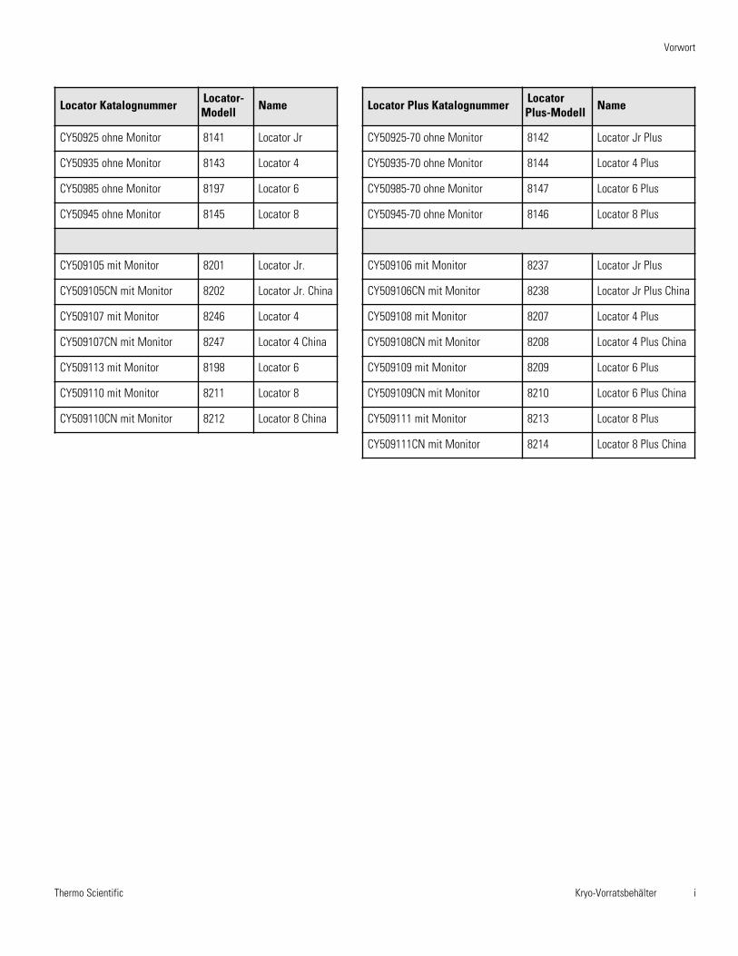
Locator Katalognummer Locator-Modell Name
CY50925 ohne Monitor 8141 Locator Jr
CY50935 ohne Monitor 8143 Locator 4
CY50985 ohne Monitor 8197 Locator 6
CY50945 ohne Monitor 8145 Locator 8
CY509105 mit Monitor 8201 Locator Jr.
CY509105CN mit Monitor 8202 Locator Jr. China
CY509107 mit Monitor 8246 Locator 4
CY509107CN mit Monitor 8247 Locator 4 China
CY509113 mit Monitor 8198 Locator 6
CY509110 mit Monitor 8211 Locator 8
CY509110CN mit Monitor 8212 Locator 8 China
Locator Plus Katalognummer LocatorPlus-Modell Name
CY50925-70 ohne Monitor 8142 Locator Jr Plus
CY50935-70 ohne Monitor 8144 Locator 4 Plus
CY50985-70 ohne Monitor 8147 Locator 6 Plus
CY50945-70 ohne Monitor 8146 Locator 8 Plus
CY509106 mit Monitor 8237 Locator Jr Plus
CY509106CN mit Monitor 8238 Locator Jr Plus China
CY509108 mit Monitor 8207 Locator 4 Plus
CY509108CN mit Monitor 8208 Locator 4 Plus China
CY509109 mit Monitor 8209 Locator 6 Plus
CY509109CN mit Monitor 8210 Locator 6 Plus China
CY509111 mit Monitor 8213 Locator 8 Plus
CY509111CN mit Monitor 8214 Locator 8 Plus China
Thermo Scientificii Kryo-Vorratsbehälter
Vorwort
Contains Parts and Assemblies
Susceptible to Damage by
Electrostatic Discharge (ESD)
CAUTIONVorsichtDiese Teile und Baugruppen
reagieren empfindlich aufelektrostatische Entladung.
Wichtig Lesen Sie diese Bedienungsanleitung. Die Nichtbeachtung dieses Handbuchs lesen, verstehenund befolgen Sie die Anweisungen kann zu Schäden an der Einheit, der Verletzung desBedienpersonals und schlechte Ausrüstung Leistung führen. Vorsicht Alle internen Einstellungen und Wartungsarbeiten müssen von qualifiziertem Servicepersonaldurchgeführt werden. Achtung Es wird empfohlen, diesen Behälter vom Hersteller oder qualifizierten cryovesselServicetechniker alle 7-10 Jahren untersucht haben, unabhängig davon, problemlos (oder derenFehlen), können Sie in der Vergangenheit gehabt haben. Dies wird helfen, Ihre Proben vor plötzlichenVerlust von flüssigem Stickstoff zu versichern durch Vakuumversagen. Warnung Stickstoffgas kann ohne Vorwarnung Erstickung führen. Speicherung und Nutzung vonflüssigem Stickstoff nur in einem gut belüfteten Ort. Da die Flüssigkeit verdampft, verdrängt dasentstehende Gas die normale Luft in der Umgebung. (Die wolkige Dampf, der beim flüssiger Stickstoff
der Luft ausgesetzt erscheint ist kondensierte Feuchtigkeit, nicht das Gas selbst. Die Ausgabe von Gas istunsichtbar.) In geschlossenen Räumen, übermäßige Mengen an Stickstoffgas reduziert die Konzentrationvon Sauerstoff und zum Ersticken führen. Da Stickstoffgas ist farblos, geruchlos, geschmacklos, kann sienicht mit den menschlichen Sinnen erfasst werden. Atmen eine Atmosphäre, die weniger als 19,5%Sauerstoff enthält, kann Schwindel verursachen und schnell zu Bewusstlosigkeit und zum Tod führen.Daher wird die Verwendung von Sauerstoff Überwachungsausrüstung stark empfohlen.
Warnkontakt von flüssigem Stickstoff mit der Haut oder den Augen kann zu schweren (Einfrieren) zuVerletzungen führen.
Warnung Nicht Rolleneinheit, um es zu bewegen.
Inhalt der Gebrauchsanleitung ist dient nur zur Information. Der Inhalt und die darin beschriebenenProduktes können ohne vorherige Ankündigung geändert werden. Thermo Fisher Scientific übernimmtkeine Gewährleistung oder Haftung in Bezug auf dieses Handbuch. In keinem Fall ist Thermo haftbar fürSchäden, die direkt oder beiläufig stattfinden wird, die sich aus oder auf die Verwendung diesesHandbuchs entstehen.
Verwendungszweck:Die Thermo Fisher Scientific kryogenen Lagerbehälter sollen biologische Proben bei Tiefsttemperaturen zuspeichern. Diese Produkte werden von einem Behälter und einem Deckel besteht, mit oder ohne eineNiveauüberwachung.Nichtbestimmungsgemäße Verwendung:Diese Produkte sind nicht für den Einsatz innerhalb der Patientenumgebung vorgesehen.
Wenn dieses Handbuch ist in andere Sprachen übersetzt, ist die US-englische Version verbindlich.
Thermo Scientific Kryo-Vorratsbehälter iii
Vorwort
Wichtige Betriebs- und/oder Wartungsvorschriften. Lesen Sie bitte den Begleittext sorgfältig durch.
Gefahr durch Elektrizität. Arbeiten, die mit diesem Symbol gekennzeichnet sind, dürfen nur vonqualifizierten Personen ausgeführt werden.
Alarm Extremumgebung. Arbeiten, die mit diesem Symbol gekennzeichnet sind, dürfen nur vonqualifizierten Personen ausgeführt werden.
Potenzielle biologische Gefahren. Die richtige Schutzausrüstung und die richtigen Verfahren müssenangewendet werden.
Kennzeichnung von elektrischen oder elektronischen Geräten, die gemäß der Richtlinie 2002/96/EC(WEEE) zur Kategorie der elektrischen oder elektronischen Einrichtungen gehören, welche nach dem13. August 2005 auf den Markt gebracht wurden.
Dieses Produkt muss die Anforderungen der EU-Richtlinie 2002/96/EC über die WEEE-Kennzeichnung von Elektro- und Elektronik-Altgeräten erfüllen. Es wurde mit einem WEEE-Symbolgekennzeichnet. Thermo Fisher Scientific wird in allen EU-Mitgliedsstaaten mit einem oder mehrerenEntsorgungs-/Recyclingunternehmen Verträge über die Entsorgung oder das Recycling diesesProdukts abschließen. Weitere Informationen über die Erfüllung der in dieser Richtlinie genanntenAnforderungen seitens Thermo und der Recyclingunternehmen sowie Informationen erhalten Sieunter www.thermofisher.com.
4 Verwenden Sie immer geeignete Schutzkleidung (Kleidung, Handschuhe, Schutzbrille etc.)
4 Sorgen Sie für eine gute Belüftung bei extrem niedrigen oder hohen Temperaturen und tragen Sie Schutzkleidung.
4 Sorgen Sie für ausreichende Sauberkeit.
4 Jede Person ist für die eigene Sicherheit verantwortlich.
Thermo Scientificiv Kryo-Vorratsbehälter
Vorwort
Benötigen Sie Informationen oder Hilfe bei derVerwendung von Thermo Scientific-Produkten?
Wenn dies der Fall ist, kontaktieren Sie bitte:
Nordamerika: USA +1-866-984-3766, Kanada +1-905-332-2000.Europa: Belgien +32 2 482 30 30, Dänemark +45 4 166 200, Finnland +358 9 329 100, Frankreich +33 2 28 03 20 00,Deutschland / Österreich / Schweiz +49 6103 4081012, Italien +39-02-2511141, Niederlande +31 76 571 4440,Russland / CIS +7 095 755 9045, Spanien / Portugal +34 93 2233154, Schweden +46 8 742 03 90,Großbritannien/Irland +44.870.609.Asien: China +86 21 5424 1582, Indien +91 22 2778 1101, Japan +81 45 453 9220,Andere asiatische Länder +86 2885 4613.Südamerika und nicht aufgelistete Länder: +33 2 2803 2000
UnsereVertriebsmitarbeiter geben Ihnen Preisauskünfte oder unterbreiten Ihnen Kostevoranschläge.Wir nehmen Ihre Bestellung auf und erteilen Auskünfte über größere Gerätelieferungen oderveranlassen, dass sich unser vor Ort befindlicher Verkaufsrepräsentant mit Ihnen in Verbindungsetzt. Unsere Produkte sind im Internet gelistet, und Sie haben die Möglichkeit, uns überunsere Homepage zu kontaktieren.
Die Mitarbeiter unseres Technischen Service unterstützen Sie mit technischen Informationenüber die richtige Einstellung, den Betrieb oder die Fehlersuche und -behebung Ihres Geräts. Wirsind ebenfalls in der Lage, Ersatz- oder Verschleißteile zu liefern oder unseren vor Ortbefindlichen Kundendienst an Sie zu verweisen. Wir unterbreiten Ihnen Kostenvoranschlägefür eine erweiterte Garantie aller Produkte von Thermo Scientific.
Wir freuen uns, wenn wir Ihnen bei allen Anwendungen behilflich sein können. Dabei ist esunerheblich, welche Produkte Sie von Thermo Scientific benötigen oder bereits verwenden.Bei technischen Problemen unterstützen wir Sie und helfen bei der Fehlersuche, so dass Sie beieinem Telefonanruf die Möglichkeit haben, Fehler selbst zu beheben, ohne den Service anrufenzu müssen.
Wenn umfangreiche Servicearbeiten erforderlich sind, unterstützen wir Sie bei Reparaturen vorOrt durch unsere qualifizierten Servicetechniker oder ein qualifiziertes Service-Unternehmen fürSchnellreparaturen. Sofern die Servicearbeiten unter die Garantie fallen, wird das Gerät aufunsere Kosten und zu Ihrer Zufriedenheit repariert.
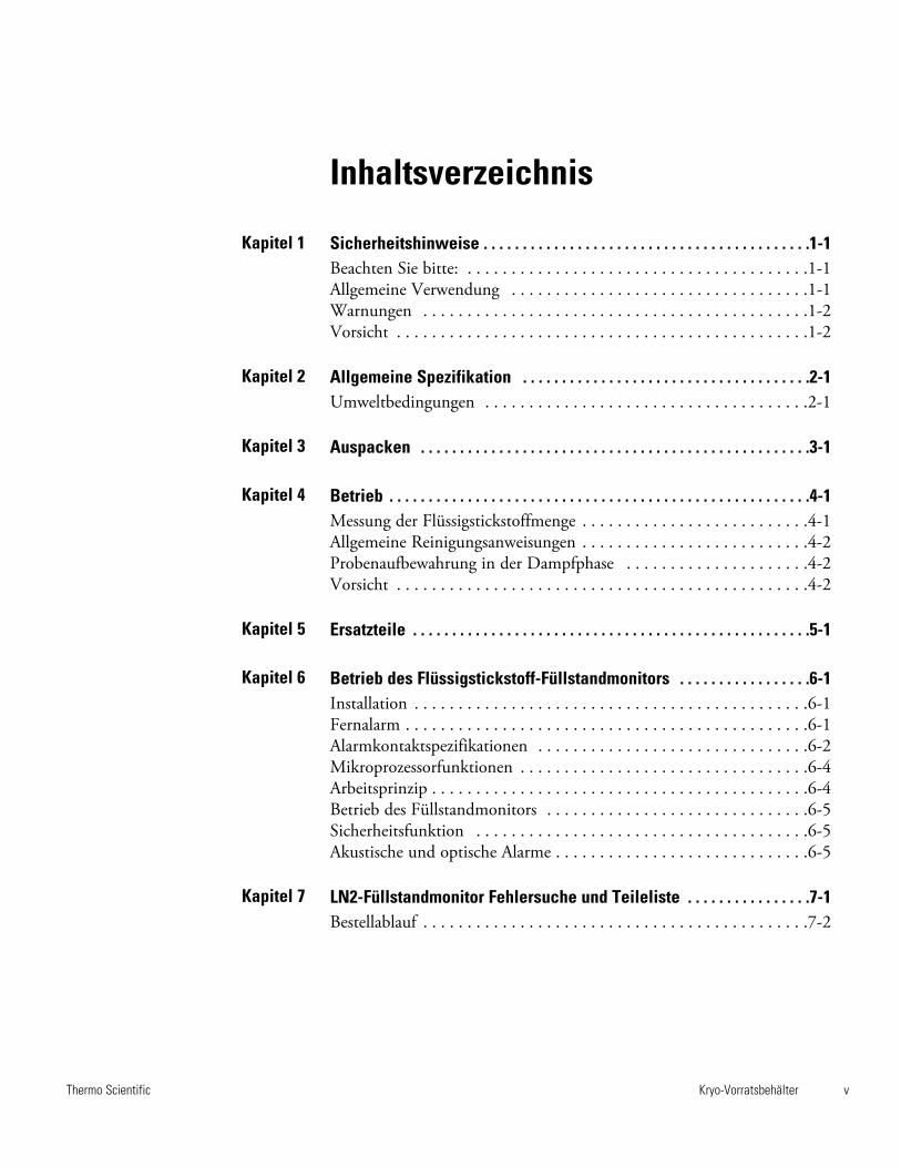
Kryo-Vorratsbehälter vThermo Scientific
Inhaltsverzeichnis
Sicherheitshinweise . . . . . . . . . . . . . . . . . . . . . . . . . . . . . . . . . . . . . . . . . .1-1Beachten Sie bitte: . . . . . . . . . . . . . . . . . . . . . . . . . . . . . . . . . . . . . . .1-1Allgemeine Verwendung . . . . . . . . . . . . . . . . . . . . . . . . . . . . . . . . . .1-1Warnungen . . . . . . . . . . . . . . . . . . . . . . . . . . . . . . . . . . . . . . . . . . . .1-2Vorsicht . . . . . . . . . . . . . . . . . . . . . . . . . . . . . . . . . . . . . . . . . . . . . . .1-2
Allgemeine Spezifikation . . . . . . . . . . . . . . . . . . . . . . . . . . . . . . . . . . . . .2-1Umweltbedingungen . . . . . . . . . . . . . . . . . . . . . . . . . . . . . . . . . . . . .2-1
Auspacken . . . . . . . . . . . . . . . . . . . . . . . . . . . . . . . . . . . . . . . . . . . . . . . . . .3-1
Betrieb . . . . . . . . . . . . . . . . . . . . . . . . . . . . . . . . . . . . . . . . . . . . . . . . . . . . . .4-1Messung der Flüssigstickstoffmenge . . . . . . . . . . . . . . . . . . . . . . . . . .4-1Allgemeine Reinigungsanweisungen . . . . . . . . . . . . . . . . . . . . . . . . . .4-2Probenaufbewahrung in der Dampfphase . . . . . . . . . . . . . . . . . . . . .4-2Vorsicht . . . . . . . . . . . . . . . . . . . . . . . . . . . . . . . . . . . . . . . . . . . . . . .4-2
Ersatzteile . . . . . . . . . . . . . . . . . . . . . . . . . . . . . . . . . . . . . . . . . . . . . . . . . . .5-1
Betrieb des Flüssigstickstoff-Füllstandmonitors . . . . . . . . . . . . . . . . .6-1Installation . . . . . . . . . . . . . . . . . . . . . . . . . . . . . . . . . . . . . . . . . . . . .6-1Fernalarm . . . . . . . . . . . . . . . . . . . . . . . . . . . . . . . . . . . . . . . . . . . . . .6-1Alarmkontaktspezifikationen . . . . . . . . . . . . . . . . . . . . . . . . . . . . . . .6-2Mikroprozessorfunktionen . . . . . . . . . . . . . . . . . . . . . . . . . . . . . . . . .6-4Arbeitsprinzip . . . . . . . . . . . . . . . . . . . . . . . . . . . . . . . . . . . . . . . . . . .6-4Betrieb des Füllstandmonitors . . . . . . . . . . . . . . . . . . . . . . . . . . . . . .6-5Sicherheitsfunktion . . . . . . . . . . . . . . . . . . . . . . . . . . . . . . . . . . . . . .6-5Akustische und optische Alarme . . . . . . . . . . . . . . . . . . . . . . . . . . . . .6-5
LN2-Füllstandmonitor Fehlersuche und Teileliste . . . . . . . . . . . . . . . .7-1Bestellablauf . . . . . . . . . . . . . . . . . . . . . . . . . . . . . . . . . . . . . . . . . . . .7-2
Kapitel 1
Kapitel 2
Kapitel 3
Kapitel 4
Kapitel 5
Kapitel 6
Kapitel 7
Kryo-Vorratsbehälter 1-1Thermo Scientific
Beachten Sie bitte:
Kapitel 1 Sicherheitshinweise
Dieses Handbuch enthält wichtige Betriebsanweisungen und Sicherheits -hinweise. Lesen Sie vor Inbetriebnahme dieses Geräts sorgfältig dasHandbuch und vergewissern Sie sich, dass Sie den Inhalt der Angabenverstanden haben.
Ihr Thermo Scientific Kryobehälter wurde unter Berücksichtigung vonFunktion, Zuverlässigkeit und Sicherheit hergestellt. Das System mussvom Benutzer gemäß den elektrischen Sicherheitsvorschriften installiertwerden. Um einen sicheren Betrieb zu gewährleisten, beachten Sie die imHandbuch angegebenen Warn- und Sicherheitshinweise.
Alle Kryobehälter nutzen, unabhängig vom Hersteller, Unterdruck, um dieextrem leitfähigen Eigenschaften zu erzeugen, die für die flüssige Form vonStickstoff unerlässlich sind. Im Wesentlichen sind sie den Thermos®-Behältern vergleichbar, die Sie für die Aufbewahrung von Kaffee, Suppeoder Milch verwenden.
Sie wissen, wie zerbrechlich diese sind? Kein Unterdruck ist perfekt undhält ewig und daher empfehlen wir, dass Sie den Verbrauch vonFlüssigstickstoff in Ihrem Behälter regelmäßig überprüfen, das heißt alle 1bis 2 Tage. Durch die Überwachung können Sie gegebenenfalls leichteVeränderung des Verbrauch ermitteln und möglicherweise auf Problemereagieren, bevor sie entstehen. Sie können sich zu diesem Zweck für dieVerwendung einer Füllstandsanzeige entscheiden (Betrieb des Füllstand -monitors siehe Seite 6-1).
Wenn es sich um extrem kritische, einzigartige oder nicht ersetzbareProben handelt, könnten Ihre Proben auf zwei separate Behälter verteilen.Denken Sie an die alte Regel, wonach man niemals alle Eier in einen Korblegen sollte...
Und weil kein Unterdruck ewig beibehalten werden kann, sollten SieIhren Behälter im Intervall von sieben bis zehn Jahren von einemqualifizierten Kryobehälterhersteller überprüfen lassen - unabhängig davon,ob es in der Vergangenheit zu Problemen gekommen ist oder nicht. Aufdiese Weise ist sichergestellt, dass Ihre Proben gegen einen plötzlichenStickstoffverlust infolge fehlenden Unterdrucks geschützt sind.
Das Produkt darf nicht für einen anderen, als den beabsichtigten Zweck,verwendet werden.
Bei nicht ordnungsgemäßer Verwendung laut Hersteller kann der für dasGerät definierte Schutz beeinträchtigt werden.
AllgemeineVerwendung
1-2 Kryo-Vorratsbehälter Thermo Scientific
Kapitel 1Sicherheitshinweise
• Der Umgang mit diesem Gerät ist geschultem Personal in einem gutbelüfteten Bereich vorbehalten.
• Flüssigstickstoff ist extrem kalt; sein Siedepunkt liegt bei -196° C.
• Beachten Sie die nachstehenden Angaben und Warnhinweisehinsichtlich möglicher Gefahren, wie Kälteverbrennungen,Frostbeulen, Erstickung usw. bei Tiefsttemperaturen.
• Lassen Sie beim Umgang mit Flüssigstickstoff, Flüssigstickstofflager-oder -transportbehältern, zerbrochenen Fläschchen und allenObjekten, die Kontakt mit Flüssigstickstoff hatten, äußerste Vorsichtwalten - es besteht die Gefahr von Kälteverbrennungen.
• Alle Hautstellen müssen bedeckt sein.
• Tragen Sie den entsprechende PSA:Schutzschild, Tiefsttemperaturhandschuhe und -schürze.
• Flüssigstickstoffbehälter dürfen nicht dicht verschlossen werden undes darf kein Stickstoffgas austreten.
• Berühren Sie Ampullen ausschließlich mit einer Zange. Bei Entnahmeaus dem Behälter besteht Explosionsgefahr.
• Lassen Sie äußerste Vorsicht walten, um das Verspritzen oderVerschütten von Flüssigstickstoff während der Entnahme des Inhaltsund der Halterung zu vermeiden.
• Entsorgen Sie Kleidung oder Schutzkleidung auf welcheFlüssigstickstoff verschüttet wurde sofort.
• Suchen Sie bei Kälteverbrennungen (Frostbeulen) durchFlüssigstickstoff sofort einen Arzt auf.
Warnungen
• Verwenden Sie ausschließlich das dem Gerät beiliegende Netzteil.
• Flüssigstickstoffbehälter nie überfüllen. Der Flüssigstickstofffüllstanddarf die Racks im Behälter niemals überschreiten. Infolge deszusätzlichen Gewichts kann der Hals brechen und dies kann zuvorzeitigem Ausfall führen.
• Beim Einsetzen oder der Entnahme von Racks müssen Sie denKontakt mit dem Halsschlauchbereich des Behälters vermeiden. DieRacks müssen in vertikaler Richtung langsam eingesetzt oderherausgenommen werden. Kratzer am Halsschlauch können zuvorzeitigem Ausfall führen.
• Entfernen oder verändern Sie keine Vakuumanschlüsse (die schwarzePlastikkappe an einer Seite des Behälters); dann verfällt derGarantieanspruch.
• Keinen Flüssigstickstoff am Vakuumanschluss verschütten - dies kannzu vorzeitigem Ausfall führen.
• Der Flüssigstickstofftransportbehälter muss immer aufrecht stehen.
• Der Locator ist kein Transportbehälter.
Kryo-Vorratsbehälter 1-3Thermo Scientific
Kapitel 1Abschnittsüberschrift
Vorsicht
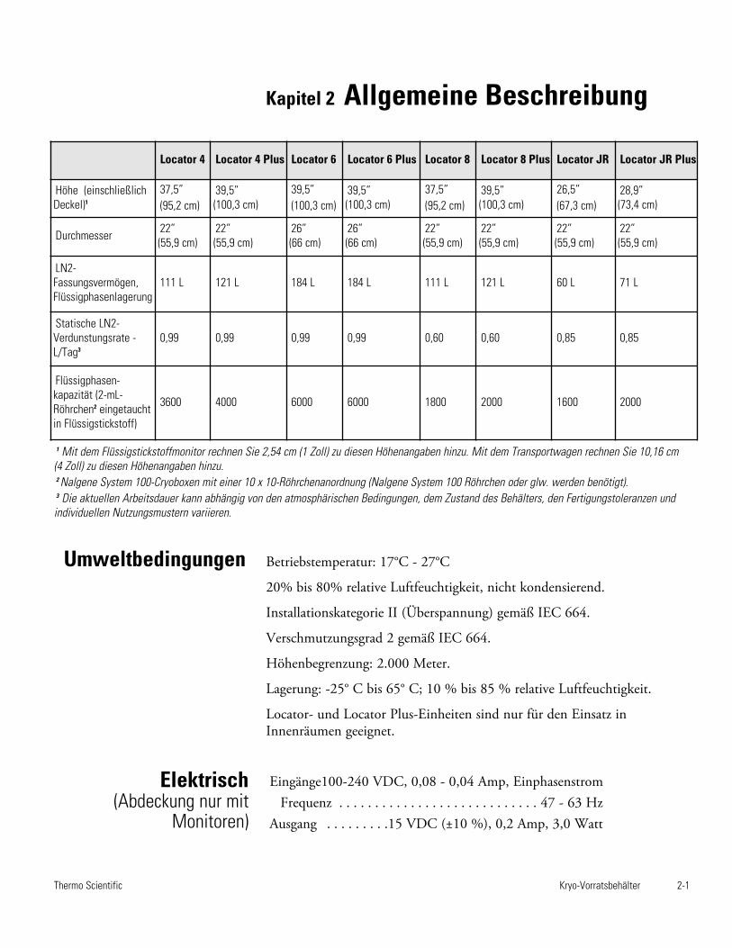
Kryo-Vorratsbehälter 2-1Thermo Scientific
Kapitel 2 Allgemeine Beschreibung
Betriebstemperatur: 17°C - 27°C
20% bis 80% relative Luftfeuchtigkeit, nicht kondensierend.
Installationskategorie II (Überspannung) gemäß IEC 664.
Verschmutzungsgrad 2 gemäß IEC 664.
Höhenbegrenzung: 2.000 Meter.
Lagerung: -25° C bis 65° C; 10 % bis 85 % relative Luftfeuchtigkeit.
Locator- und Locator Plus-Einheiten sind nur für den Einsatz inInnenräumen geeignet.
Locator 4 Locator 4 Plus Locator 6 Locator 6 Plus Locator 8 Locator 8 Plus Locator JR Locator JR Plus
Höhe (einschließlichDeckel)1
37,5” (95,2 cm)
39,5” (100,3 cm)
39,5”(100,3 cm)
39,5” (100,3 cm)
37,5” (95,2 cm)
39,5” (100,3 cm)
26,5” (67,3 cm)
28,9” (73,4 cm)
Durchmesser 22” (55,9 cm)
22” (55,9 cm)
26” (66 cm)
26” (66 cm)
22” (55,9 cm)
22” (55,9 cm)
22” (55,9 cm)
22” (55,9 cm)
LN2-Fassungsvermögen,Flüssigphasenlagerung
111 L 121 L 184 L 184 L 111 L 121 L 60 L 71 L
Statische LN2-Verdunstungsrate -L/Tag3
0,99 0,99 0,99 0,99 0,60 0,60 0,85 0,85
Flüssigphasen -kapazität (2-mL-Röhrchen2 eingetauchtin Flüssigstickstoff)
3600 4000 6000 6000 1800 2000 1600 2000
1 Mit dem Flüssigstickstoffmonitor rechnen Sie 2,54 cm (1 Zoll) zu diesen Höhenangaben hinzu. Mit dem Transportwagen rechnen Sie 10,16 cm(4 Zoll) zu diesen Höhenangaben hinzu.2 Nalgene System 100-Cryoboxen mit einer 10 x 10-Röhrchenanordnung (Nalgene System 100 Röhrchen oder glw. werden benötigt).3 Die aktuellen Arbeitsdauer kann abhängig von den atmosphärischen Bedingungen, dem Zustand des Behälters, den Fertigungstoleranzen undindividuellen Nutzungsmustern variieren.
Umweltbedingungen
Elektrisch (Abdeckung nur mit
Monitoren)
Eingänge100-240 VDC, 0,08 - 0,04 Amp, EinphasenstromFrequenz . . . . . . . . . . . . . . . . . . . . . . . . . . . . 47 - 63 Hz
Ausgang . . . . . . . . .15 VDC (±10 %), 0,2 Amp, 3,0 Watt
Kryo-Vorratsbehälter 3-1Thermo Scientific
Kapitel 3 Auspacken
Inspizieren Sie den Locator- oder Locator Plus-Behälter vor dererstmaligen Verwendung aufmerksam. Achten Sie auf möglicheTransportschäden. Es ist ratsam, alle neuen Einheiten mit Flüssigstickstoffzu befüllen (siehe Befüllanleitungen) und die Flüssigstickstoffverlustratewährend einiger Tage zu beobachten. Wenden Sie sich bei Problemenschnellstmöglich an den technischen Kundendienst.
Füllen Sie bitte die dem Behälter beigefügte Garantiekarte aus und sendenSie diese innerhalb von 30 Tagen an den Hersteller zurück, damit wirIhnen die ordnungsgemäße Garantie zusichern können. Diese Angabenmüssen die Seriennummer enthalten, die Sie bitte dem Aufkleber amBehälter entnehmen.
Hinweis Mechanisches Versagen ist eine der Hauptursachen für denvorzeitigen Ausfall in Zusammenhang mit Flüssigstickstoffbehältern. DerHalsschlauch trägt das gesamte Gewicht des Innenbehälters mit dem darinenthaltenen Flüssigstickstoff. Bei einem Schlag auf die Seiten oder Eckendes Behälters schlägt der Innenbehälter in einer Pendelbewegung aus undkann den Hals beschädigen. Behälter, die herabgefallen sind oderabgesenkt und an einer der Ecken einem Schlag ausgesetzt werden, sindfehleranfälliger. s
Vorsicht Lassen Sie beim Transport des Locator- oder Locator Plus-Behälters äußerste Vorsicht walten. Kryobiologische Locator- oder LocatorPlus-Lagerbehälter sind keine Transportbehälter. Die Transportwagen sindlediglich für den Transport innerhalb des Labors oder zwischen Laborsgeeignet. Der Transport gefüllter Behälter über lange Strecken, Risse imBoden, Schwellen, geneigte Rampen oder in Aufzügen kann zu vorzeitigemAusfall führen. Vermeiden Sie übermäßige Kraft beim Bewegen Schiffes; dies kann Kippen verursachen, was zu Schäden und / oder Verschütten von flüssigem Stickstoff.s
Hinweis Wenn Proben unter Kryobedingungen transportiert werdenmüssen, empfehlen wir die Thermo Scientific Arctic ExpressTrockenversandbehälter. s
Kryo-Vorratsbehälter 4-1Thermo Scientific
Kapitel 4 Betrieb
Vorsicht Überfüllen Sie einen Locator- oder Locator Plus-Behälterniemals mit Flüssigstickstoff. Der Flüssigstickstofffüllstand im Tank (miteingesetzten Racks) darf die folgenden Werte niemals überschreiten.Locator 4 50 cm (20 Zoll), Locator 8 25 cm (10 Zoll), Locator Jr. 55,8 cm(22 Zoll), Locator 4, 5 und 8 sowie Locator Jr. Plus 30,48 cm (12 Zoll).Wenn der Tank bis oder über den Halsschlauch gefüllt wird, kann dies zuvorzeitigem Vakuumverlust führen. s
Vorsicht Beim Einsetzen oder der Entnahme von Racks müssen Sie denKontakt mit dem Halsschlauchbereich des Behälters vermeiden. Die Racksmüssen in vertikaler Richtung langsam eingesetzt oder herausgenommenwerden. Kratzer am Halsschlauch können zu vorzeitigem Ausfall führen. s
Vorsicht Entfernen oder verändern Sie keine Vakuumanschlüsse (dieschwarze Plastikkappe an einer Seite des Behälters). Dies kann zuvorzeitigem Ausfall führen. s
Um Beschädigungen des Locator- oder Locator Plus-Kryolagerbehältersund vorzeitigen Vakuumverlust zu vermeiden, muss das nachstehendeVerfahren während des Auffüllens eines warmen Behälters mitFlüssigstickstoff eingehalten werden.
1. Füllen Sie nur eine kleine Menge Flüssigstickstoff (5 bis 10 Liter) inneue oder warme Behälter.
2. Lassen Sie diese geringfügige Flüssigstickstoffmenge mindestens zweiStunden im abgedeckten Behälter einwirken. Dann vermindern sichdie Belastungen infolge plötzlicher Temperaturschwankungen beimHinzufügen von Flüssigstickstoff in einen warmen Behälter.
3. Geben Sie zusätzlich 15 Liter LN2 in den Behälter.
4. Lassen Sie den Behälter 48 Stunden ruhen und beobachten Sie denFlüssigstickstoffverbrauch; optional können Sie dazu einen Messstab(Teilenr. 180143) oder den Füllstandmonitor verwenden.
5. Befüllen Sie den Locator oder Locator Plus wie angegeben (siehe“Vorsicht” in diesem Kapitel). Beachten Sie die Verdrängung vonFlüssigstickstoff während des Einsetzens von Racks.
6. Racks langsam einsetzen und herausnehmen. Den Flüssigstickstoff ausden Boxen und von den Racks ablaufen lassen.
Befüllungsanleitungen
4-2 Kryo-Vorratsbehälter Thermo Scientific
Kapitel 4Betrieb
1. Das Flüssigstickstoffniveau mit einem Messstab prüfen (Teilenr.180143). KEINE Hohlstäbe oder Rohre als Messstab fürFlüssigstickstoff verwenden.
2. Der Füllstand ist die angezeigte Frostlinie, die sich nach demEntfernen des Messstabs entwickelt.
3. Der Füllstandmonitor ist für konstante Messungen geeignet. SieheKapitel 6.
1. Nehmen Sie die beiden tiefsten Cryoboxen aus den Racks.
2. Messen Sie die Höhe von zwei aufeinander gestapelten Cryoboxen.
3. Befüllen Sie den Behälter bis zu der in Schritt 2 ermittelten Höhe mitLN2; messen Sie den Füllstand im Behälter mit einem Messstab.
4. Setzen Sie die Racks ohne die beiden unteren Cryoboxen in denBehälter. Die Proben befinden sich nun über dem Flüssigstickstoff undsind in der Dampfphase gelagert.
Wichtig Das LN2-Niveau ist in der Dampfphase sehr niedrig und dahersollte immer ein Füllstandmonitor verwendet werden. Hinweise zumgeeigneten Füllstandmonitor für Ihr System entnehmen Sie Kapitel 5.
Außenflächen mit einem leicht feuchten Tuch und einer mildenSeifenlösung abwischen.
Probenaufbewahrungin der Dampfphase
AllgemeineReinigungsanweisungen
Messung derFlüssigstickstoffmenge
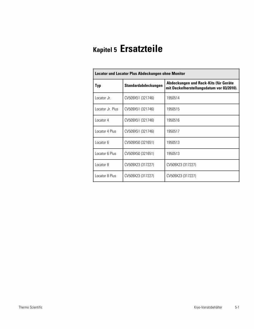
Kryo-Vorratsbehälter 5-1Thermo Scientific
Kapitel 5 Ersatzteile
Locator und Locator Plus Abdeckungen ohne Monitor
Typ Standardabdeckungen Abdeckungen und Rack-Kits (für Gerätemit Deckelherstellungsdatum vor 03/2010).
Locator Jr. CV509X51 (321746) 1950514
Locator Jr. Plus CV509X51 (321746) 1950515
Locator 4 CV509X51 (321746) 1950516
Locator 4 Plus CV509X51 (321746) 1950517
Locator 6 CV509X50 (321651) 1950513
Locator 6 Plus CV509X50 (321651) 1950513
Locator 8 CV509X23 (317227) CV509X23 (317227)
Locator 8 Plus CV509X23 (317227) CV509X23 (317227)

5-2 Kryo-Vorratsbehälter Thermo Scientific
Kapitel 5Ersatzteile
Katalognummer Rack-Beschreibung
HR509X15A (317050) Für Locator Jr (8141, 8201, 8202) mit 4 - 2-Zoll-Boxen
HR509X2A (317161) Für Locator 4 (8143, 8246, 8247) mit 9 - 2-Zoll-Boxen
HR509X19A (315903) Für Locator Jr (8141, 8201, 8202) mit 2 - 4-Zoll-Boxen
HR509X20A (315905) Für Locator 4 (8143, 8246, 8247) mit 5 - 4-Zoll-Boxen
HR509X15A-70 (317148) Für Locator Jr Plus (8142, 8237, 8238) mit 5 - 2-Zoll-Boxen
HR509X2A-70 (317175) Für Locator 4 Plus (8144, 8207, 8208) mit 10 - 2-Zoll-Boxen
HR509X31A-70 (317192) Für Locator 6 und 6 Plus (8147, 8197, 8198, 8209, 8210) mit 10 - 2-Zoll-Boxen
HR509X1A (317205) Für Locator 8 (8211, 8212, 8145) mit 9 - 2-Zoll-Boxen (25 Zellen)
HR509X1A-70 (317217) Für Locator 8 Plus (8146, 8213, 8214) mit 10 - 2-Zoll-Boxen (25 Zelle)
HR509X19A-70 (315904) Für Locator Jr. Plus (8142, 8237, 8238) mit 2 - 4 Zoll-Boxen + 1 - 2-Zoll-Box
HR509X20A-70 (315906) Für Locator 4 Plus (8144, 8207, 8208) mit 5 - 4 Zoll-Boxen + 1 - 2-Zoll-Box
HR509X32A-70 (315907) Für Locator 6 und 6 Plus (8147, 8197, 8198, 8209, 8210) mit 5 - 4 Zoll-Boxen + 1 - 2-Zoll-Box
Kapitel 6 Betrieb des Flüssigstickstoff-Füllstandmonitors
Dieser (LN2) Flüssigstickstoff-Füllstandmonitor zeigt das LN2-Niveaukonstant an und informiert Sie mittels akustischer und optischer Alarmeüber Füllstandveränderungen. Er informiert Sie, sobald der Behälter gefülltwerden muss. Der Füllstandmonitor wird mit der entsprechendenmontierten Locator- oder Locator Plus-Abdeckung versendet. Er kann miteinem Fernalarmsystem verbunden werden damit Sie auch dann überProbleme informiert werden, wenn Sie sich nicht im Labor aufhalten.Dieses System wurde für den Betrieb mit einem vom Hersteller gestelltenexternen Netzteil entwickelt. Es wurde ausschließlich für ThermoScientific LN2-Behälter entwickelt.
Vorsicht Dieses Produkt darf nur in Innenräumen verwendet werden. s
Warnung Gefahr durch Elektrizität. Arbeiten, die mit diesem Symbolgekennzeichnet sind, dürfen nur von qualifizierten Personen ausgeführtwerden. s
Hinweise Wenn der Füllstandmonitor gemeinsam mit einem Locator-oder Locator Plus-System erworben wurde, fahren Sie bitte mit Schritt 3vor. Sollte es sich um die Nachrüstung eines Locator oder Locator Plushandeln, beginnen Sie bitte mit Schritt 1. s
1. Nehmen Sie den Füllstandmonitor und den Locator oder Locator Plusaus dem Karton.
2. Nehmen Sie die Abdeckung von Ihrem Locator oder Locator Plus abund tauschen Sie diese gegen Ihren neuen Füllstandmonitor und dieAbdeckung aus.
3. Überprüfen Sie die elektrischen Daten am Netzteil und verbinden Siees mit einer geerdeten Steckdose.
Kryo-Vorratsbehälter 6-1Thermo Scientific
Installation
1. Trennen Sie den LN2-Füllstandmonitor vom Netzteil. UnterbrechenSie die Stromversorgung zum Alarmsystem.
2. Lösen Sie die drei Schrauben an der Abdeckung des LN2-Füllstandmonitors. Ziehen Sie die Abdeckung ab (siehe Abb. 6-1).
Sobald der LN2-Füllstandmonitor mit einem Alarmsystem verbunden ist,werden Sie auch dann über Probleme informiert, wenn das Laborunbesetzt ist. Die Alarmkontakte des Gerätes werden aktiviert, sobald derakustische Alarm auslöst (siehe Mikroprozessor-Funktionen).
3. Lösen Sie den schwarzen Stecker an der Seite der Abdeckung. FührenSie die Kabel für den Fernalarm durch diese Öffnung.
4. Siehe Abb. 6-1, -2 und -3 für die Anbringung der Fernalarmkontakte.
5. Die LN2-Füllstandmonitorabdeckung wieder anbringen. VerbindenSie den LN2-Füllstandmonitor und das Fernalarmsystem wieder mitdem Stromnetz.
Hinweis Der LN2-Füllstandmonitor kann mit einem normal geöffnetenoder normal geschlossenen Kontakt konfiguriert werden. Der gewählteModus ist von der Stellung eines einzelnen Jumpers auf der Platineabhängig. Für einen normal geöffneten Kontakt wird der Jumper auf J6gesetzt. Für einen normal geschlossenen Kontakt wird der Jumper auf J4gesetzt (siehe Abb. 6-2). Kontrollieren Sie die richtige Jumper-Setzung fürIhr Fernalarmsystem. s
Der Alarmkontakt des LN2-Füllstandmonitors ist ein Photomos-Relais.
Kontaktform: Typ 1 Form BMax. Ladespannung: 24 VDC max. Max. Ladestrom: 120 m Typischer Widerstand: Max. 26 Ω
6-2 Kryo-Vorratsbehälter Thermo Scientific
Kapitel 6Betrieb des LN2-Füllstandmonitors
Alarmkontakt-spezifikationen
Füllstandmonitor Fernalarm
Fernalarmverbindung
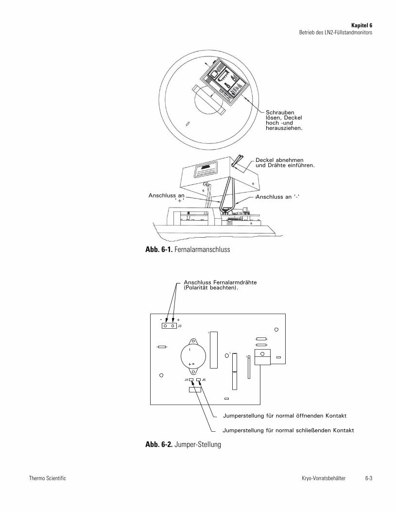
Kryo-Vorratsbehälter 6-3Thermo Scientific
Kapitel 6Betrieb des LN2-Füllstandmonitors
1
1
1
For normally closed contact, place jumper here.
For normally open contact, place jumper here.
Remote Alarm wires connect here (Note polarity.)
- +J3
J4 J6
Abb. 6-1. Fernalarmanschluss
Abb. 6-2. Jumper-Stellung
Schraubenlösen, Deckelhoch -undherausziehen.
Deckel abnehmenund Drähte einführen.
Anschluss an '-'Anschluss an'+'
Anschluss Fernalarmdrähte(Polarität beachten).
Jumperstellung für normal öffnenden Kontakt
Jumperstellung für normal schließenden Kontakt
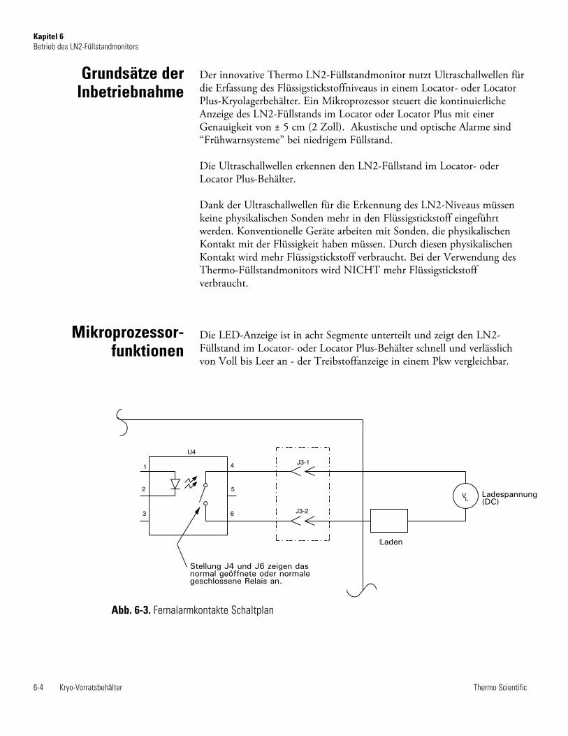
Der innovative Thermo LN2-Füllstandmonitor nutzt Ultraschallwellen fürdie Erfassung des Flüssigstickstoffniveaus in einem Locator- oder LocatorPlus-Kryolagerbehälter. Ein Mikroprozessor steuert die kontinuierlicheAnzeige des LN2-Füllstands im Locator oder Locator Plus mit einerGenauigkeit von ± 5 cm (2 Zoll). Akustische und optische Alarme sind“Frühwarnsysteme” bei niedrigem Füllstand.
Die Ultraschallwellen erkennen den LN2-Füllstand im Locator- oderLocator Plus-Behälter.
Dank der Ultraschallwellen für die Erkennung des LN2-Niveaus müssenkeine physikalischen Sonden mehr in den Flüssigstickstoff eingeführtwerden. Konventionelle Geräte arbeiten mit Sonden, die physikalischenKontakt mit der Flüssigkeit haben müssen. Durch diesen physikalischenKontakt wird mehr Flüssigstickstoff verbraucht. Bei der Verwendung desThermo-Füllstandmonitors wird NICHT mehr Flüssigstickstoffverbraucht.
Die LED-Anzeige ist in acht Segmente unterteilt und zeigt den LN2-Füllstand im Locator- oder Locator Plus-Behälter schnell und verlässlichvon Voll bis Leer an - der Treibstoffanzeige in einem Pkw vergleichbar.
6-4 Kryo-Vorratsbehälter Thermo Scientific
Kapitel 6Betrieb des LN2-Füllstandmonitors
Grundsätze derInbetriebnahme
Mikroprozessor-funktionen
Abb. 6-3. Fernalarmkontakte Schaltplan
1
2
3 6
5
4
Load
J3-2
J3-1
U4
V Load Voltage(DC)
L
The position of J4 and J6 indicatewhether the relay is normally openor normally closed.
Ladespannung(DC)
Laden
Stellung J4 und J6 zeigen dasnormal geöffnete oder normalegeschlossene Relais an.
1. Die Meldeleuchte “LOW LEVEL” (niedriges Niveau) leuchtetkontinuierlich, wenn das Flüssigstickstoffniveau circa 5 cm (2-Zoll)unterschreitet. Dann ist der Füllstand des Flüssigstickstoffs niedrig undSie werden informiert, dass Sie den Behälter schnellstmöglich auffüllenmüssen.
2. Ein AKUSTISCHER und entfernter Alarm wird kontinuierlichaktiviert, wenn das LN2-Niveau circa 2,54 cm (1 Zoll) im Locator-oder Locator Plus-Behälter unterschreitet. Zusätzlich blinkt “LOWLEVEL” kontinuierlich. Dann ist der Füllstand des Flüssigstickstoffsgefährlich niedrig und Sie werden informiert, dass Sie den Behälterunverzüglich auffüllen müssen.
3. Die AKUSTISCHEN und Fernalarme sind kontinuierlich aktiviert,die 8-Segment-LED-Anzeige und die “LOW LEVEL”-Meldeleuchteblinken und zeigen den Notfall an. Dieser Alarm wird ausgelöst, wennsich im Locator- oder Locator Plus-Behälter kein Flüssigstickstoff mehrbefindet oder der Monitor fehlerhaft arbeitet und das LN2-Niveaunicht erkennen kann.
Der Mikroprozessor muss jedes Mal zurückgesetzt werden, nachdem dieAbdeckung vom Locator oder Locator Plus abgenommen wurde. Vor demAbnehmen der Abdeckung muss die Taste RESET gedrückt werden;dann leuchtet die RESET-Meldeleuchte. In diesem Rücksetz-/Halte-Modus sind die Messfunktionen des Monitors deaktiviert. Nach fünf (5)Minuten im Rücksetz-/Halte-Modus werden ein akustischer und einFernalarm aktiviert, die Sie daran erinnern, dass der Rücksetz-/Halte-Modus deaktiviert werden muss, wenn die Abdeckung wieder auf denBehälter gesetzt wird.
Sobald der Deckel mit dem Monitor auf den Behälter gesetzt undeingesteckt wurde lassen Sie das System circa 15 Minuten ruhen, bevor Siedie Reset-Taste für die akkurate Messung des Flüssigstickstoffniveausdrücken. Dieser Anpassungsprozess muss immer durchgeführt werden,wenn die Abdeckung abgenommen wird. Immer, wenn ein Behältergeöffnet oder bewegt wird, beeinflusst dies die stabilisierteKammertemperatur und/oder den Flüssigkeitsfüllstand negativ. DasSystem benötigt eine stabile Temperatur und einen stabilen Füllstand,damit das exakte FN2-Niveau ermittelt werden kann.
Wenn Sie einen neuen Locator oder Locator Plus mit Ihrem Monitorerworben haben, muss sich der Flüssigstickstoff mindestens einen Tag imBehälter anpassen, bevor Sie das Gerät anschließen. So vermeiden SieFehlalarme.
Nach Nachdem der Füllstandmonitor auf den Kryobehälter gesetzt wurdekönnen bis zur Anzeige des Messwerts zehn (10) Minuten vergehen;dasselbe gilt, nachdem der Kryobehälter bewegt wurde. Nachdem Sie dasGerät auf den Behälter gesetzt haben, müssen Sie “Reset” drücken. Dannerlischt die grüne LED am Schalter. s
Kryo-Vorratsbehälter 6-5Thermo Scientific
Kapitel 6Betrieb des LN2-Füllstandmonitors
Akustische undoptische Alarme
Sicherheitsfunktion
Betrieb desFüllstandmonitors
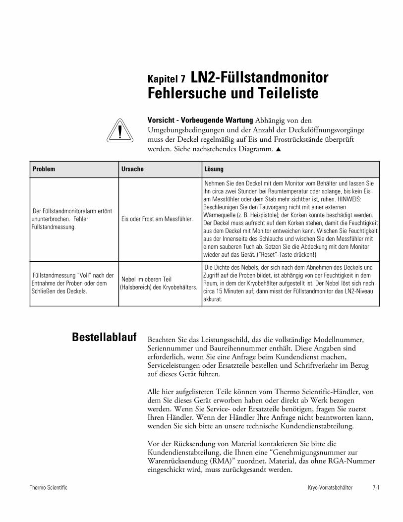
Kapitel 7 LN2-FüllstandmonitorFehlersuche und Teileliste
Kryo-Vorratsbehälter 7-1Thermo Scientific
Problem Ursache Lösung
Der Füllstandmonitoralarm ertönt ununterbrochen. FehlerFüllstandmessung.
Eis oder Frost am Messfühler.
Nehmen Sie den Deckel mit dem Monitor vom Behälter und lassen Sieihn circa zwei Stunden bei Raumtemperatur oder solange, bis kein Eisam Messfühler oder dem Stab mehr sichtbar ist, ruhen. HINWEIS:Beschleunigen Sie den Tauvorgang nicht mit einer externenWärmequelle (z. B. Heizpistole); der Korken könnte beschädigt werden.Der Deckel muss aufrecht auf dem Korken stehen, damit die Feuchtigkeitaus dem Deckel mit Monitor entweichen kann. Wischen Sie Feuchtigkeitaus der Innenseite des Schlauchs und wischen Sie den Messfühler miteinem sauberen Tuch ab. Setzen Sie die Abdeckung mit dem Monitorwieder auf das Gerät. (“Reset”-Taste drücken!)
Füllstandmessung “Voll” nach derEntnahme der Proben oder demSchließen des Deckels.
Nebel im oberen Teil(Halsbereich) des Kryobehälters.
Die Dichte des Nebels, der sich nach dem Abnehmen des Deckels undZugriff auf die Proben bildet, ist abhängig von der Feuchtigkeit in demRaum, in dem der Kryobehälter aufgestellt ist. Der Nebel löst sich nachcirca 15 Minuten auf; dann misst der Füllstandmonitor das LN2-Niveauakkurat.
Bestellablauf Beachten Sie das Leistungsschild, das die vollständige Modellnummer,Seriennummer und Baureihennummer enthält. Diese Angaben sinderforderlich, wenn Sie eine Anfrage beim Kundendienst machen,Serviceleistungen oder Ersatzteile bestellen und Schriftverkehr im Bezugauf dieses Gerät führen.
Alle hier aufgelisteten Teile können vom Thermo Scientific-Händler, vondem Sie dieses Gerät erworben haben oder direkt ab Werk bezogenwerden. Wenn Sie Service- oder Ersatzteile benötigen, fragen Sie zuerstIhren Händler. Wenn der Händler Ihre Anfrage nicht beantworten kann,wenden Sie sich bitte an unsere technische Kundendienstabteilung.
Vor der Rücksendung von Material kontaktieren Sie bitte dieKundendienstabteilung, die Ihnen eine “Genehmigungsnummer zurWarenrücksendung (RMA)” zuordnet. Material, das ohne RGA-Nummereingeschickt wird, muss zurückgesandt werden.
Vorsicht - Vorbeugende Wartung Abhängig von denUmgebungsbedingungen und der Anzahl der Deckelöffnungsvorgängemuss der Deckel regelmäßig auf Eis und Frostrückstände überprüftwerden. Siehe nachstehendes Diagramm. s
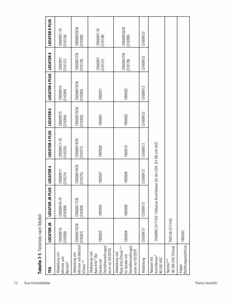
7-2 Kryo-Vorratsbehälter Thermo Scientific
TEIL
LO
CATO
R JR
LOCA
TOR
JR P
LUS
LOCA
TOR
4LO
CATO
R 4
PLU
SLO
CATO
R 6
LOCA
TOR
6 PL
US
LOCA
TOR
8LO
CATO
R 8
PLU
S
Abde
ckun
g m
itM
onito
r und
Net
ztei
l*
CN50
9X16
(316
306)
CN50
9X16
-70
(316
308)
CN50
9X17
(316
374)
CN50
9X17
-70
(316
376)
CN50
9X15
(316
304)
CN50
9X15
(316
304)
CN50
9X7
(316
137)
CN50
9X7-
70(3
1613
8)
Abde
ckun
g m
itM
onito
r und
Net
ztei
l(C
hina
) **
CN50
9X16
CN(3
1630
7)
CN50
9X17
CN(3
1630
9)CN
509X
18CN
(316
375)
CN50
9X19
CN(3
1637
7)CN
509X
15CN
(316
305)
CN50
9X15
CN(3
1630
5)CN
509X
7CN
(316
139)
CN50
9X20
CN(3
1639
0)
Abde
ckun
g un
dRa
ck-K
its*
(für
Gerä
te m
itDe
ckel
hers
tellu
ngsd
atum
vor
03/
2010
).
1950
503
1950
505
1950
507
1950
509
1950
501
1950
501
CN50
9X7
(316
137)
CN50
9X7-
70(3
1613
8)
Abde
ckun
g un
dRa
ck-K
its (C
hina
) **
für G
erät
e m
itDe
ckel
hers
tellu
ngsd
atum
vor
03/
2010
1950
504
1950
506
1950
508
1950
510
1950
502
1950
502
CN50
9X7C
N(3
1613
9)CN
509X
20CN
(316
390)
Abde
ckun
g CV
509X
13CV
509X
13CV
509X
13
CV50
9X13
CV
509X
13
CV50
9X13
CV
509X
13
CV50
9X13
Net
ztei
l mit
Ansc
hlüs
sen*
90
-240
VAC
TN50
9X2
(317
133)
*in
klus
ive
Ansc
hlüs
sen
für d
ie U
SA, E
U GB
und
AUS
.
Net
ztei
l**
90-2
64 V
AC (C
hina
)TN
X136
(317
143)
Kapp
eBe
lüftu
ngsa
nsch
luss
1950
343
Tabe
lle 7
-1. T
eile
liste
nac
h M
odel
l
Locator e Locator PlusContenitore per conservazione criogenica
con o senza monitoraggio ad ultrasuoni del livello di azoto.Manuale d’uso ed elenco dei componenti
LT509X9 Rev. 4
© 2014 Thermo Fisher ScientificTutti i diritti riservatiStampato negli U.S.A.
User M
anual
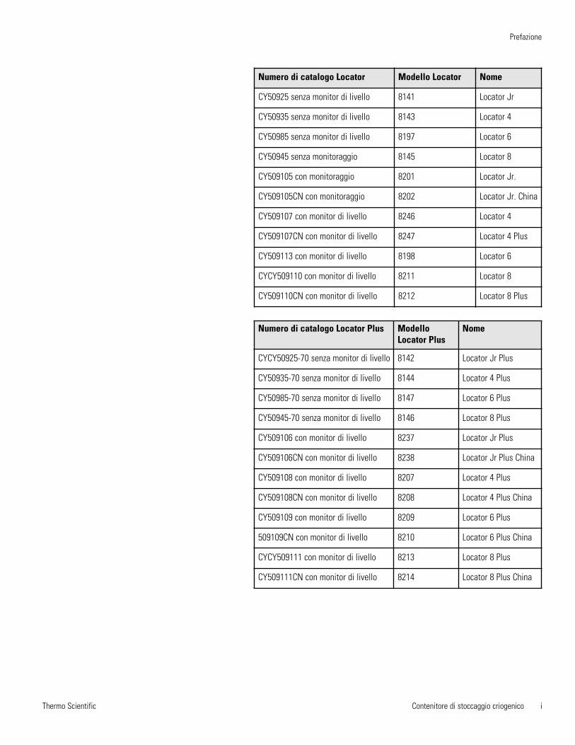
Thermo Scientific
Prefazione
Contenitore di stoccaggio criogenico i
Numero di catalogo Locator Modello Locator Nome
CY50925 senza monitor di livello 8141 Locator Jr
CY50935 senza monitor di livello 8143 Locator 4
CY50985 senza monitor di livello 8197 Locator 6
CY50945 senza monitoraggio 8145 Locator 8
CY509105 con monitoraggio 8201 Locator Jr.
CY509105CN con monitoraggio 8202 Locator Jr. China
CY509107 con monitor di livello 8246 Locator 4
CY509107CN con monitor di livello 8247 Locator 4 Plus
CY509113 con monitor di livello 8198 Locator 6
CYCY509110 con monitor di livello 8211 Locator 8
CY509110CN con monitor di livello 8212 Locator 8 Plus
Numero di catalogo Locator Plus ModelloLocator Plus
Nome
CYCY50925-70 senza monitor di livello 8142 Locator Jr Plus
CY50935-70 senza monitor di livello 8144 Locator 4 Plus
CY50985-70 senza monitor di livello 8147 Locator 6 Plus
CY50945-70 senza monitor di livello 8146 Locator 8 Plus
CY509106 con monitor di livello 8237 Locator Jr Plus
CY509106CN con monitor di livello 8238 Locator Jr Plus China
CY509108 con monitor di livello 8207 Locator 4 Plus
CY509108CN con monitor di livello 8208 Locator 4 Plus China
CY509109 con monitor di livello 8209 Locator 6 Plus
509109CN con monitor di livello 8210 Locator 6 Plus China
CYCY509111 con monitor di livello 8213 Locator 8 Plus
CY509111CN con monitor di livello 8214 Locator 8 Plus China
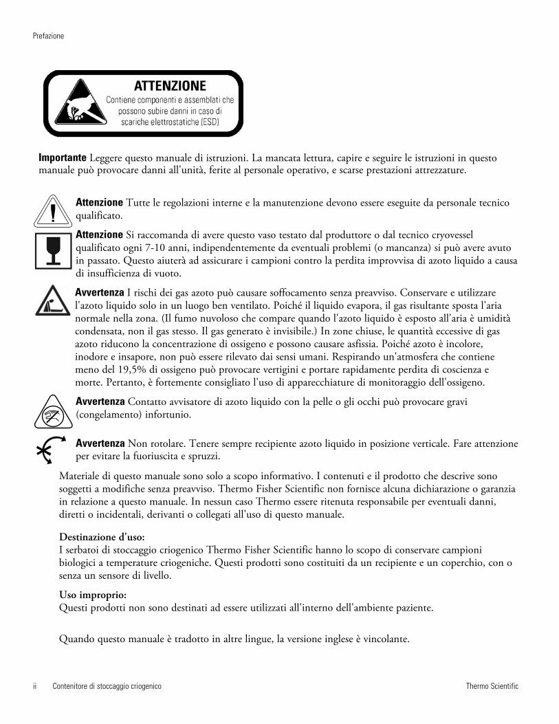
Thermo Scientificii Contenitore di stoccaggio criogenico
Prefazione
Importante Leggere questo manuale di istruzioni. La mancata lettura, capire e seguire le istruzioni in questo manuale può provocare danni all'unità, ferite al personale operativo, e scarse prestazioni attrezzature.
Attenzione Tutte le regolazioni interne e la manutenzione devono essere eseguite da personale tecnicoqualificato.
Attenzione Si raccomanda di avere questo vaso testato dal produttore o dal tecnico cryovesselqualificato ogni 7-10 anni, indipendentemente da eventuali problemi (o mancanza) si può avere avutoin passato. Questo aiuterà ad assicurare i campioni contro la perdita improvvisa di azoto liquido a causadi insufficienza di vuoto.
Avvertenza I rischi dei gas azoto può causare soffocamento senza preavviso. Conservare e utilizzarel'azoto liquido solo in un luogo ben ventilato. Poiché il liquido evapora, il gas risultante sposta l'arianormale nella zona. (Il fumo nuvoloso che compare quando l'azoto liquido è esposto all'aria è umiditàcondensata, non il gas stesso. Il gas generato è invisibile.) In zone chiuse, le quantità eccessive di gasazoto riducono la concentrazione di ossigeno e possono causare asfissia. Poiché azoto è incolore,inodore e insapore, non può essere rilevato dai sensi umani. Respirando un'atmosfera che contienemeno del 19,5% di ossigeno può provocare vertigini e portare rapidamente perdita di coscienza emorte. Pertanto, è fortemente consigliato l'uso di apparecchiature di monitoraggio dell'ossigeno.
Avvertenza Contatto avvisatore di azoto liquido con la pelle o gli occhi può provocare gravi(congelamento) infortunio.
Avvertenza Non rotolare. Tenere sempre recipiente azoto liquido in posizione verticale. Fare attenzione per evitare la fuoriuscita e spruzzi.
Materiale di questo manuale sono solo a scopo informativo. I contenuti e il prodotto che descrive sonosoggetti a modifiche senza preavviso. Thermo Fisher Scientific non fornisce alcuna dichiarazione o garanziain relazione a questo manuale. In nessun caso Thermo essere ritenuta responsabile per eventuali danni,diretti o incidentali, derivanti o collegati all'uso di questo manuale.
Destinazione d'uso:I serbatoi di stoccaggio criogenico Thermo Fisher Scientific hanno lo scopo di conservare campionibiologici a temperature criogeniche. Questi prodotti sono costituiti da un recipiente e un coperchio, con osenza un sensore di livello.
Uso improprio:Questi prodotti non sono destinati ad essere utilizzati all'interno dell'ambiente paziente.
Quando questo manuale è tradotto in altre lingue, la versione inglese è vincolante.
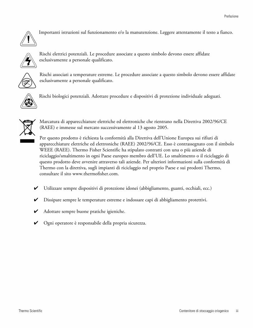
Thermo Scientific Contenitore di stoccaggio criogenico iii
Prefazione
Importanti istruzioni sul funzionamento e/o la manutenzione. Leggere attentamente il testo a fianco.
Rischi elettrici potenziali. Le procedure associate a questo simbolo devono essere affidateesclusivamente a personale qualificato.
Rischi associati a temperature estreme. Le procedure associate a questo simbolo devono essere affidateesclusivamente a personale qualificato.
Rischi biologici potenziali. Adottare procedure e dispositivi di protezione individuale adeguati.
Marcatura di apparecchiature elettriche ed elettroniche che rientrano nella Direttiva 2002/96/CE(RAEE) e immesse sul mercato successivamente al 13 agosto 2005.
Per questo prodotto è richiesta la conformità alla Direttiva dell’Unione Europea sui rifiuti diapparecchiature elettriche ed elettroniche (RAEE) 2002/96/CE. Esso è contrassegnato con il simboloWEEE (RAEE). Thermo Fisher Scientific ha stipulato contratti con una o più aziende diriciclaggio/smaltimento in ogni Paese europeo membro dell’UE. Lo smaltimento o il riciclaggio diquesto prodotto deve avvenire attraverso tali aziende. Per ulteriori informazioni sulla conformità diThermo con la direttiva, sugli impianti di riciclaggio nel proprio Paese e sui prodotti Thermo,consultare il sito www.thermofisher.com.
4 Utilizzare sempre dispositivi di protezione idonei (abbigliamento, guanti, occhiali, ecc.)
4 Dissipare sempre le temperature estreme e indossare capi di abbigliamento protettivi.
4 Adottare sempre buone pratiche igieniche.
4 Ogni operatore è responsabile della propria sicurezza.
Thermo Scientificiv Contenitore di stoccaggio criogenico
Prefazione
Il nostro personale di assistenza alle vendite è in grado di fornire preventivi e informazioni sui prezzi, ricevere gli ordini e fornire informazioni sulle apparecchiature principali, oppure organizzare una visita del rappresentante locale presso il cliente. I nostri prodotti sono presenti su Internet e possiamo essere contattati attraverso il nostro sito.
Il nostro personale di assistenza è in grado di fornire informazioni sulla corretta configurazione, sul funzionamento e sulla risoluzione dei guasti delle apparecchiature. Inoltre siamo in grado di soddisfare le vostre esigenze di accessori e ricambi e fornire assistenza in loco. Su richiesta forniamo preventivi sulla garanzia estesa a copertura dei prodotti Thermo Scientific. Quali che siano i prodotti Thermo Scientific che utilizzate o di cui avete necessità, sar emo lieti di esaminare con voi le vostre applicazioni.
In caso di problemi tecnici, lavorando con voi vi aiuteremo a individuare l’anomalia e in molti casi a risolverla da soli, con una semplice telefonata non di servizio. In caso di assistenza più specifica, vi invieremo i nostri tecnici specializzati o vi indicheremo un centro di assistenza qualificato per le riparazioni in loco. Se l’assistenza è coperta dalla garanzia, provvederemo a riparare l’apparecchio a nostre spese.
Vi occorrono informazioni o assistenza per i prodotti Thermo Fisher Scientific?
Contattateci ai seguenti numeri:
Nord America: USA +1-866-984-3766, Canada +1-905-332-2000. Europa: Belgio +32 2 482 30 30, Danimarca +45 4 166 200, Finlandia +358 9 329 100, Francia +33 2 28 03 20 00, Germania / Austria / Svizzera +49 6103 4081012, Italia +39-02-2511141, Paesi Bassi +31 76 571 4440, Russia / CIS +7 095 755 9045, Spagna / Portogallo +34 93 2233154, Svezia +46 8 742 03 90, UK / Irlanda +44 870 609 9203.Asia: Cina +86 21 5424 1582, India +91 22 2778 1101, Giappone +81 45 453 9220, Altri Paesi asiatici+86 2885 4613. Sud America e Paesi non elencati: +33 2 2803 2000
Contenitore di stoccaggio criogenico vThermo Scientific
Sommario
Informazioni sulla sicurezza . . . . . . . . . . . . . . . . . . . . . . . . . . . . . . . . . . .1-1Informazioni importanti . . . . . . . . . . . . . . . . . . . . . . . . . . . . . . . . . . .1-1Uso generale . . . . . . . . . . . . . . . . . . . . . . . . . . . . . . . . . . . . . . . . . . . .1-1Avvertenze . . . . . . . . . . . . . . . . . . . . . . . . . . . . . . . . . . . . . . . . . . . . .1-2Precauzioni . . . . . . . . . . . . . . . . . . . . . . . . . . . . . . . . . . . . . . . . . . . . .1-2
Specifiche generali . . . . . . . . . . . . . . . . . . . . . . . . . . . . . . . . . . . . . . . . . .2-1Condizioni ambientali . . . . . . . . . . . . . . . . . . . . . . . . . . . . . . . . . . . .2-1
Rimozione dell’imballo . . . . . . . . . . . . . . . . . . . . . . . . . . . . . . . . . . . . . . . .3-1
Funzionamento . . . . . . . . . . . . . . . . . . . . . . . . . . . . . . . . . . . . . . . . . . . . . . .4-1Istruzioni per il rifornimento . . . . . . . . . . . . . . . . . . . . . . . . . . . . . . .4-1Misurazione della quantità di azoto liquido . . . . . . . . . . . . . . . . . . . .4-2Stoccaggio di campioni in fase vaporosa . . . . . . . . . . . . . . . . . . . . . . .4-2Istruzioni generali sulla pulizia . . . . . . . . . . . . . . . . . . . . . . . . . . . . . .4-2
Parti di ricambio . . . . . . . . . . . . . . . . . . . . . . . . . . . . . . . . . . . . . . . . . . . . .5-1
Funzionamento del sistema di monitoraggio del livello di azoto liquido . . . . . . . . . . . . . . . . . . . . . . . . . . . . . . . . . . . . . . . . . . . . . . . . . . . . . .6-1Installazione . . . . . . . . . . . . . . . . . . . . . . . . . . . . . . . . . . . . . . . . . . . .6-1Monitoraggio del livello Allarme remoto . . . . . . . . . . . . . . . . . . . . . .6-2Specifiche del contatto dell’allarme . . . . . . . . . . . . . . . . . . . . . . . . . .6-2Principi di funzionamento . . . . . . . . . . . . . . . . . . . . . . . . . . . . . . . . .6-4Funzioni del microprocessore . . . . . . . . . . . . . . . . . . . . . . . . . . . . . . .6-4Allarmi acustici e visivi . . . . . . . . . . . . . . . . . . . . . . . . . . . . . . . . . . . .6-5Funzioni di sicurezza . . . . . . . . . . . . . . . . . . . . . . . . . . . . . . . . . . . . .6-5Funzionamento del monitoraggio del . . . . . . . . . . . . . . . . . . . . . . . . .6-5
Risoluzione problemi del sistema di monitoraggio del livello dell’LN2 ed elenco dei componenti . . . . . . . . . . . . . . . . . . . . . . . . . . . . .7-1Procedure di ordinazione . . . . . . . . . . . . . . . . . . . . . . . . . . . . . . . . . .7-1
Sezione 1
Sezione 2
Sezione 3
Sezione 4
Sezione 5
Sezione 6
Sezione 7
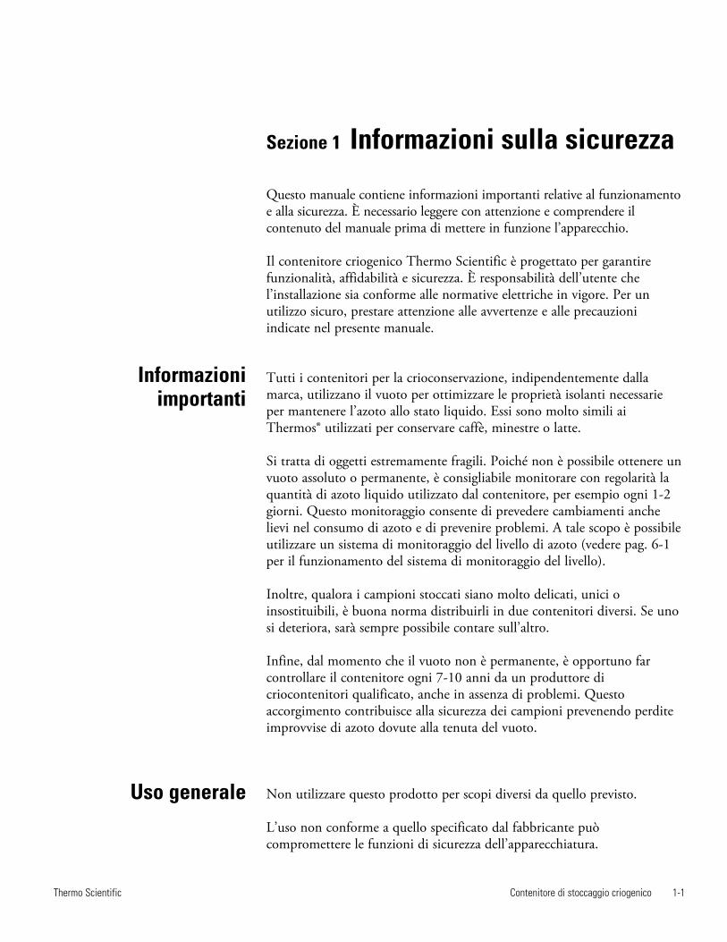
Contenitore di stoccaggio criogenico 1-1Thermo Scientific
Informazioniimportanti
Sezione 1 Informazioni sulla sicurezza
Questo manuale contiene informazioni importanti relative al funzionamentoe alla sicurezza. È necessario leggere con attenzione e comprendere ilcontenuto del manuale prima di mettere in funzione l’apparecchio.
Il contenitore criogenico Thermo Scientific è progettato per garantirefunzionalità, affidabilità e sicurezza. È responsabilità dell’utente chel’installazione sia conforme alle normative elettriche in vigore. Per unutilizzo sicuro, prestare attenzione alle avvertenze e alle precauzioniindicate nel presente manuale.
Tutti i contenitori per la crioconservazione, indipendentemente dallamarca, utilizzano il vuoto per ottimizzare le proprietà isolanti necessarieper mantenere l’azoto allo stato liquido. Essi sono molto simili aiThermos® utilizzati per conservare caffè, minestre o latte.
Si tratta di oggetti estremamente fragili. Poiché non è possibile ottenere unvuoto assoluto o permanente, è consigliabile monitorare con regolarità laquantità di azoto liquido utilizzato dal contenitore, per esempio ogni 1-2giorni. Questo monitoraggio consente di prevedere cambiamenti anchelievi nel consumo di azoto e di prevenire problemi. A tale scopo è possibileutilizzare un sistema di monitoraggio del livello di azoto (vedere pag. 6-1per il funzionamento del sistema di monitoraggio del livello).
Inoltre, qualora i campioni stoccati siano molto delicati, unici oinsostituibili, è buona norma distribuirli in due contenitori diversi. Se unosi deteriora, sarà sempre possibile contare sull’altro.
Infine, dal momento che il vuoto non è permanente, è opportuno farcontrollare il contenitore ogni 7-10 anni da un produttore dicriocontenitori qualificato, anche in assenza di problemi. Questoaccorgimento contribuisce alla sicurezza dei campioni prevenendo perditeimprovvise di azoto dovute alla tenuta del vuoto.
Non utilizzare questo prodotto per scopi diversi da quello previsto.
L’uso non conforme a quello specificato dal fabbricante puòcompromettere le funzioni di sicurezza dell’apparecchiatura.
Uso generale
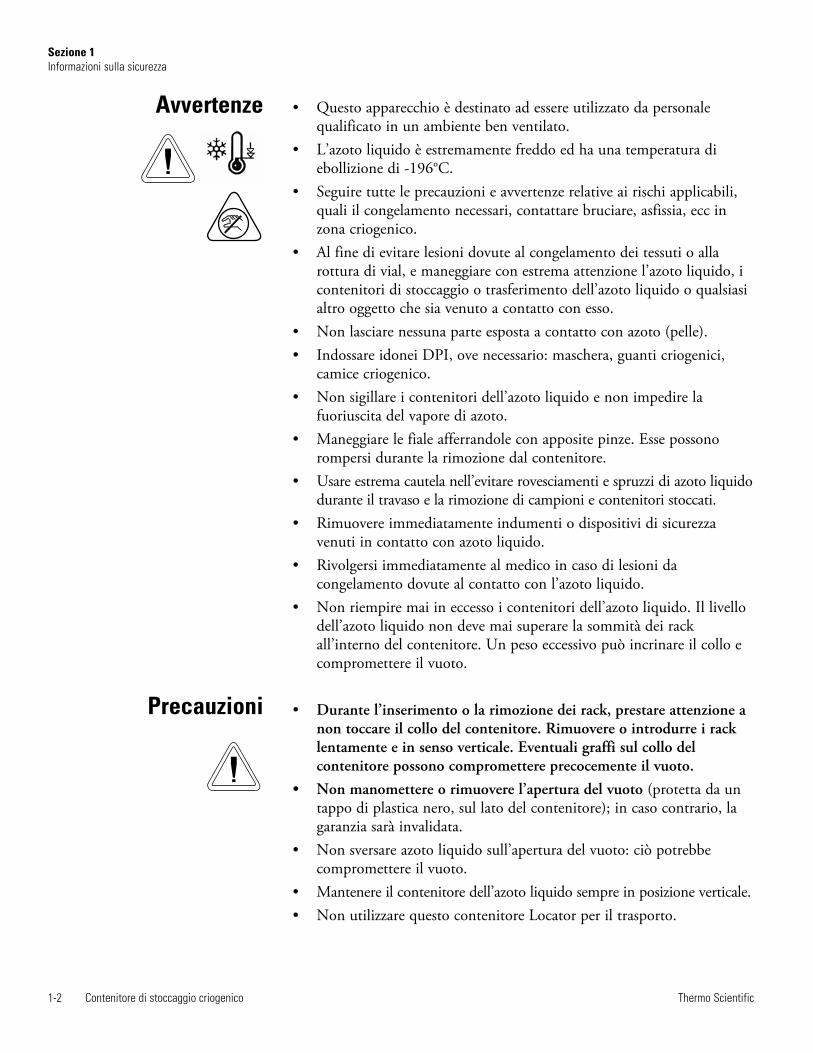
1-2 Contenitore di stoccaggio criogenico Thermo Scientific
Sezione 1Informazioni sulla sicurezza
Precauzioni
• Questo apparecchio è destinato ad essere utilizzato da personalequalificato in un ambiente ben ventilato.
• L’azoto liquido è estremamente freddo ed ha una temperatura diebollizione di -196°C.
• Seguire tutte le precauzioni e avvertenze relative ai rischi applicabili,quali il congelamento necessari, contattare bruciare, asfissia, ecc inzona criogenico.
• Al fine di evitare lesioni dovute al congelamento dei tessuti o allarottura di vial, e maneggiare con estrema attenzione l’azoto liquido, icontenitori di stoccaggio o trasferimento dell’azoto liquido o qualsiasialtro oggetto che sia venuto a contatto con esso.
• Non lasciare nessuna parte esposta a contatto con azoto (pelle).• Indossare idonei DPI, ove necessario: maschera, guanti criogenici,
camice criogenico.• Non sigillare i contenitori dell’azoto liquido e non impedire la
fuoriuscita del vapore di azoto.• Maneggiare le fiale afferrandole con apposite pinze. Esse possono
rompersi durante la rimozione dal contenitore.• Usare estrema cautela nell’evitare rovesciamenti e spruzzi di azoto liquido
durante il travaso e la rimozione di campioni e contenitori stoccati.• Rimuovere immediatamente indumenti o dispositivi di sicurezza
venuti in contatto con azoto liquido.• Rivolgersi immediatamente al medico in caso di lesioni da
congelamento dovute al contatto con l’azoto liquido.• Non riempire mai in eccesso i contenitori dell’azoto liquido. Il livello
dell’azoto liquido non deve mai superare la sommità dei rackall’interno del contenitore. Un peso eccessivo può incrinare il collo ecompromettere il vuoto.
• Durante l’inserimento o la rimozione dei rack, prestare attenzione anon toccare il collo del contenitore. Rimuovere o introdurre i racklentamente e in senso verticale. Eventuali graffi sul collo delcontenitore possono compromettere precocemente il vuoto.
• Non manomettere o rimuovere l’apertura del vuoto (protetta da untappo di plastica nero, sul lato del contenitore); in caso contrario, lagaranzia sarà invalidata.
• Non sversare azoto liquido sull’apertura del vuoto: ciò potrebbecompromettere il vuoto.
• Mantenere il contenitore dell’azoto liquido sempre in posizione verticale.• Non utilizzare questo contenitore Locator per il trasporto.
Avvertenze
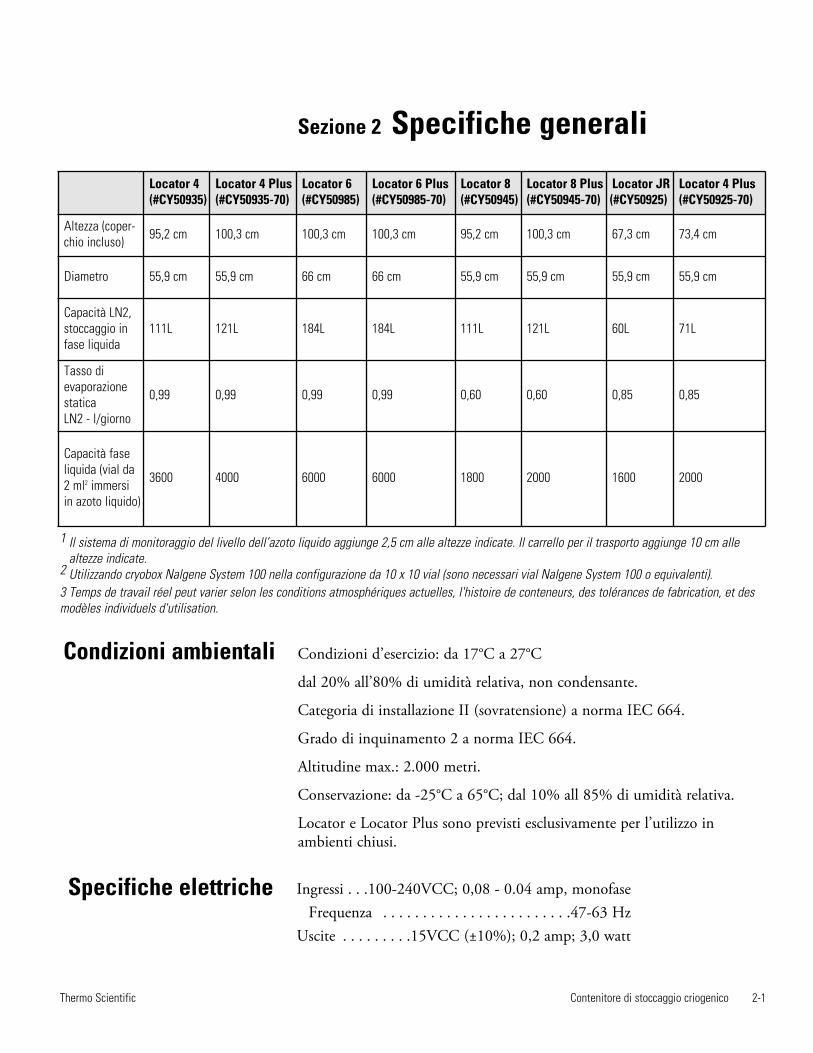
Contenitore di stoccaggio criogenico 2-1Thermo Scientific
Sezione 2 Specifiche generali
Condizioni d’esercizio: da 17°C a 27°C
dal 20% all’80% di umidità relativa, non condensante.
Categoria di installazione II (sovratensione) a norma IEC 664.
Grado di inquinamento 2 a norma IEC 664.
Altitudine max.: 2.000 metri.
Conservazione: da -25°C a 65°C; dal 10% all 85% di umidità relativa.
Locator e Locator Plus sono previsti esclusivamente per l’utilizzo inambienti chiusi.
Locator 4(#CY50935)
Locator 4 Plus(#CY50935-70)
Locator 6(#CY50985)
Locator 6 Plus(#CY50985-70)
Locator 8(#CY50945)
Locator 8 Plus(#CY50945-70)
Locator JR(#CY50925)
Locator 4 Plus(#CY50925-70)
Altezza (coper-chio incluso) 95,2 cm 100,3 cm 100,3 cm 100,3 cm 95,2 cm 100,3 cm 67,3 cm 73,4 cm
Diametro 55,9 cm 55,9 cm 66 cm 66 cm 55,9 cm 55,9 cm 55,9 cm 55,9 cm
Capacità LN2,stoccaggio infase liquida
111L 121L 184L 184L 111L 121L 60L 71L
Tasso dievaporazionestatica LN2 - l/giorno
0,99 0,99 0,99 0,99 0,60 0,60 0,85 0,85
Capacità faseliquida (vial da2 ml2 immersi in azoto liquido)
3600 4000 6000 6000 1800 2000 1600 2000
1 Il sistema di monitoraggio del livello dell’azoto liquido aggiunge 2,5 cm alle altezze indicate. Il carrello per il trasporto aggiunge 10 cm allealtezze indicate.
2 Utilizzando cryobox Nalgene System 100 nella configurazione da 10 x 10 vial (sono necessari vial Nalgene System 100 o equivalenti).3 Temps de travail réel peut varier selon les conditions atmosphériques actuelles, l'histoire de conteneurs, des tolérances de fabrication, et desmodèles individuels d'utilisation.
Condizioni ambientali
Specifiche elettriche Ingressi . . .100-240VCC; 0,08 - 0.04 amp, monofaseFrequenza . . . . . . . . . . . . . . . . . . . . . . . .47-63 Hz
Uscite . . . . . . . . .15VCC (±10%); 0,2 amp; 3,0 watt
Contenitore di stoccaggio criogenico 3-1Thermo Scientific
Sezione 3 Rimozione dell’imballo
Esaminare attentamente il contenitore Locator o Locator Plus nuovo primadell’uso. Controllare che non abbia subito danni durante il trasporto. Èconsigliabile riempire tutte le unità nuove (vedere le Istruzioni per ilrifornimento) con azoto liquido e monitorare per alcuni gionri, la perditadi azoto. In caso di problemi, rivolgersi al più presto al centro di assistenzaai clienti.
La scheda di Registrazione della garanzia fornita con il contenitore deveessere compilata e inviata alla fabbrica entro 30 giorni per attivare lagaranzia. Le informazioni devono includere il numero di serie indicatosull’etichetta del contenitore.
Nota Le cause più frequenti di deterioramento dei contenitori distoccaggio ad azoto liquido sono di natura meccanica. Il collo delcontenitore sostiene interamente il peso dell’involucro interno e dell’azotoliquido in esso contenuto. Un urto laterale provoca l’oscillazionedell’involucro interno con un moto simile a quello di un pendolo,danneggiando il collo del contenitore. I contenitori che abbiano subitoincidenti, cadute o urti laterali si possono rovinare rispetto agli altri. s
Attenzione Spostare il contenitore Locator o Locator Plus con estremacautela. I sistemi di stoccaggio criobiologico Locator e Locator Plus nonsono indicati per il trasporto. I carrelli per il trasporto sono concepiti perfavorire lo spostamento all’interno del laboratorio o da un laboratorioall’altro. Il trasporto di contenitori pieni su distanze lunghe, pavimentisconnessi, soglie, rampe inclinate o ascensori può provocare ildeterioramento precoce del vuoto. Evitare l'uso di forza eccessiva Quandosi sposta nave; questo può causare ribaltamento, con conseguenti danni e /o di fuoriuscita di azoto liquido. s
Nota Per il trasporto di campioni in condizioni criogeniche, si consiglia lalinea di contenitori a secco Thermo Scientific Arctic Express. s
Contenitore di stoccaggio criogenico 4-1Thermo Scientific
Sezione 4 Funzionamento
Attenzione Non riempire mai eccessivamente il contenitore Locator oLocator Plus con azoto liquido. Il livello di azoto liquido all’interno delserbatoio (con i rack inseriti) non deve mai superare 50 cm per Locator 4 eLocator 8; 25 cm per Locator Jr.; 55,8 cm per Locator 4, 6 e 8 Plus e30,5 cm per Locator Jr. Plus. Riempire il serbatoio fino o oltre la base delcollo può provocare il deterioramento immediato o del sistema di vuoto. s
Attenzione Durante l’inserimento o la rimozione dei rack, prestareattenzione a non toccare il collo del contenitore. Rimuovere o introdurre irack lentamente e in senso verticale. Eventuali graffi sul collo delcontenitore possono compromettere precocemente il vuoto. s
Attenzione Non rovesciare azoto liquido sul foro di accesso del vuoto(protetta da un tappo di plastica nero, sul lato del contenitore). Ciòpotrebbe compromettere il vuoto. s
Al fine di evitare danni al contenitore di stoccaggio criogenico Locator oLocator Plus, che potrebbero comportare la compromettere il vuoto, èimportante seguire la procedura descritta sotto per l’aggiunta di azotoliquido in un contenitore a temperatura ambiente:
1. Aggiungere solo una modesta quantità di azoto liquido (5-10 litri) inun contenitore nuovo o a temperatura ambiente.
2. Lasciare riposare questo quantitativo di azoto liquido all’interno delcontenitore chiuso per almeno 2 ore. Questo accorgimento consente diridurre al minimo lo stress provocato dall’improvviso sbalzo termicodovuto all’aggiunta di azoto liquido nel contenitore a temperaturaambiente.
3. Aggiungere altri 15 litri di azoto liquido nel contenitore.
4. Lasciare riposare il contenitore per 48 ore e monitorare il consumo diazoto liquido per mezzo di un’asticella in legno, dell’asta opzionale(n. parte 180143) o del sistema di monitoraggio del livello.
5. Riempire Locator o Locator Plus come indicato (vedere il richiamoall’attenzione in questa sezione). L’inserimento di canister e cannecomporta uno spostamento del liquido.
6. Inserire e rimuovere i canister con lentezza. Attendere la fuoriuscitadell’azoto dalle scatole e dai rack.
Istruzioni per ilrifornimento
4-2 Contenitore di stoccaggio criogenico Thermo Scientific
Sezione 4Funzionamento
1. Per misurare il livello dell’azoto liquido utilizzare un’asta di legno ol’asta opzionale (n. parte 180143). Non servirsi MAI di tubi, cavi o diaste di plastica.
2. Il livello corrisponde dalla linea ghiacciata che si forma all’estrazionedell’asta.
3. Per monitorare costantemente il livello è possibile servirsi di unapposito sistema di monitoraggio. Vedere la Sezione 6.
1. Rimuovere le 2 cryobox più in basso di ogni rack.
2. Misurare l’altezza di 2 cryobox sovrapposte.
3. Riempire il contenitore con azoto liquido fino all’altezza ottenuta alpunto 2, servendosi di un’asta per misurare il livello del liquido.
4. Introdurre i rack nel contenitore senza le 2 cryobox inferiori. Icampioni si trovano adesso al di sopra dell’azoto liquido, stoccati invapori di azoto.
Importante Lo stoccaggio dei campioni in fase di vapori di azoto richiedesempre l’uso di un sistema di monitoraggio del livello (a causa del bassolivello dell’azoto liquido). Consultare la Sezione 5 per il corretto sistema dimonitoraggio del livello per l’apparecchio in dotazione. s
Strofinare le superfici esterne con un panno leggermente inumidito conacqua e sapone neutro.
Stoccaggio dicampioni in fase
vaporosa
Istruzioni generalisulla pulizia
Misurazione dellaquantità di azoto
liquido
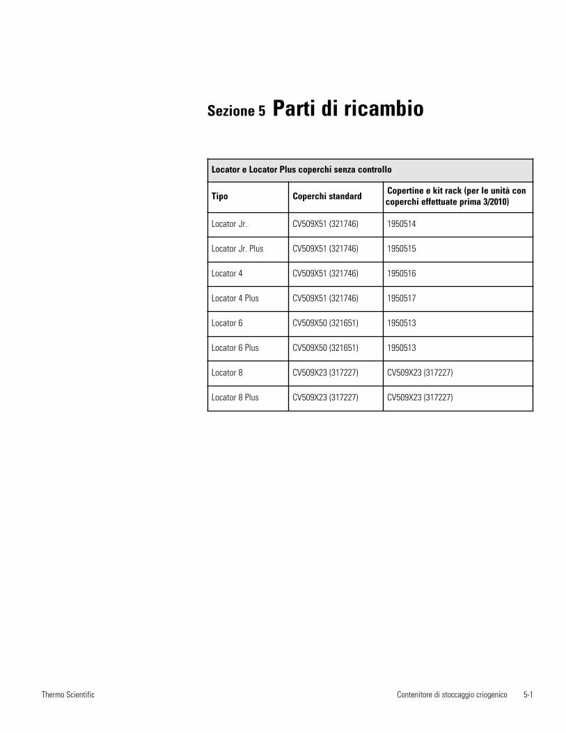
Contenitore di stoccaggio criogenico 5-1Thermo Scientific
Sezione 5 Parti di ricambio
Locator e Locator Plus coperchi senza controllo
Tipo Coperchi standard Copertine e kit rack (per le unità concoperchi effettuate prima 3/2010)
Locator Jr. CV509X51 (321746) 1950514
Locator Jr. Plus CV509X51 (321746) 1950515
Locator 4 CV509X51 (321746) 1950516
Locator 4 Plus CV509X51 (321746) 1950517
Locator 6 CV509X50 (321651) 1950513
Locator 6 Plus CV509X50 (321651) 1950513
Locator 8 CV509X23 (317227) CV509X23 (317227)
Locator 8 Plus CV509X23 (317227) CV509X23 (317227)

5-2 Cryogenic Storage Vessel Thermo Scientific
Section 5Parti di ricambio
Catalogo # Descrizione Cremagliera
HR509X15A (317050) For Locator Jr (8141, 8201, 8202) with 4 - 2 inch boxes
HR509X2A (317161) For Locator 4 (8143, 8246, 8247) with 9 - 2 inch boxes
HR509X19A (315903) For Locator Jr (8141, 8201, 8202) with 2 - 4 inch boxes
HR509X20A (315905) For Locator 4 (8143, 8246, 8247) with 5 - 4 inch boxes
HR509X15A-70 (317148) For Locator Jr Plus (8142, 8237, 8238) with 5 - 2 inch boxes
HR509X2A-70 (317175) For Locator 4 Plus (8144, 8207, 8208) with 10 - 2 inch boxes
HR509X31A-70 (317192) For Locator 6 and 6 Plus (8147, 8197, 8198, 8209, 8210) with 10 - 2 inch boxes
HR509X1A (317205) For Locator 8 (8211, 8212, 8145) with 9 - 2 inch boxes (25 cell)
HR509X1A-70 (317217) For Locator 8 Plus (8146, 8213, 8214) with 10 - 2 inch boxes (25 cell)
HR509X19A-70 (315904) For Locator Jr. Plus (8142, 8237, 8238) with 2 - 4 inch boxes + 1 - 2 inch box
HR509X20A-70 (315906) For Locator 4 Plus (8144, 8207, 8208) with 5 - 4 inch boxes + 1 - 2 inch box
HR509X32A-70 (315907) For Locator 6 and 6 Plus (8147, 8197, 8198, 8209, 8210) with 5 - 4 inch boxes + 1 - 2 inch box
Sezione 6 Funzionamento del sistemadi monitoraggio del livello di azotoliquido
Il sistema di monitoraggio dell’azoto liquido (LN2) fornisce un’indicazionecontinua del livello dell’LN2 e segnala l’abbassamento del livello medianteallarmi acustici e visivi. Esso avvisa quando il contenitore necessita di unrifornimento e in caso di condizioni di perdita eccessiva di LN2. Il sistemadi monitoraggio è fornito già montato sul coperchio del contenitoreLocator o Locator Plus. Può essere collegato a un sistema di allarmeremoto in modo da segnalare l’insorgenza di problemi anche durante leassenze dell’operatore dal laboratorio. Questo apparecchio deve esserecollegato a un alimentatore esterno fornito dal fabbricante. È concepitoesclusivamente per l’uso con contenitori a LN2 Thermo Scientific.
Attenzione Questo prodotto deve essere utilizzato esclusivamente per loscopo previsto. s
Avvertenza Rischi elettrici potenziali. Le procedure associate a questosimbolo devono essere affidate esclusivamente a personale qualificato. s
Nota Se il sistema di monitoraggio del livello è stato acquistato come parteintegrante di un sistema Locator o Locator Plus, passare direttamente alpunto 3. Se si tratta di un retrofit per un sistema Locator o Locator Plusesistente, iniziare dal punto 1. s
1. Estrarre dall’imballo il sistema di monitoraggio del livello e ilcoperchio di Locator o Locator Plus.
2. Rimuovere dal contenitore Locator o Locator Plus il coperchio in uso esostituirlo con il nuovo coperchio con sistema di monitoraggio dellivello.
3. Controllare le specifiche elettriche indicate sull’alimentatore ecollegarlo a una presa elettrica dotata di messa a terra.
Contenitore di stoccaggio criogenico 6-1Thermo Scientific
Installazione
1. Scollegare il sistema di monitoraggio del livello di azoto liquidodall’alimentazione. Scollegare il sistema di allarme dall’alimentazione.
2. Rimuovere le tre viti che fissano il coperchio del sistema dimonitoraggio del livello di azoto liquido. Sollevare e rimuovere ilcoperchio (vedere la Figura 6-1).
Se collegato al sistema di allarme remoto, il sistema di monitoraggio dellivello di LN2 segnala eventuali problemi in assenza di personale nellaboratorio. I contatti di allarme dell’unità sono attivati nel momentostesso in cui viene emesso l’allarme acustico (vedere la Sezione Funzioni delmicroprocessore).
3. Togliere il tappo nero dal lato del coperchio. Introdurre i cavidell’allarme remoto in questa apertura.
4. Collegare i cavi dell’allarme remoto come illustrato nelle Figure 6-1,2 e 3.
5. Sostituire il coperchio del sistema di monitoraggio del livello di LN2.Ricollegare il sistema di monitoraggio e l’allarme remotoall’alimentazione.
Nota Il sistema di monitoraggio del livello di LN2 può essere configuratocon contatto normalmente aperto o normalmente chiuso. La modalitàoperativa corrente dipende dal posizionamento di un singolo jumper sulcircuito stampato. Per il contatto normalmente aperto, il jumper deveessere collocato su J6. Per il contatto normalmente chiuso, il jumper deveessere collocato su J4 (vedere la Figura 6-2). Verificare che il jumper perl’allarme remoto sia collocato correttamente. s
Il contatto dell’allarme del sistema di monitoraggio del livello di LN2 è unrelè di tipo Photomos.
Forma di contatto: Tipo 1 forma BCarico tensione max.: 24VCC Max Carico corrente max.: 120mA Resistenza tipica all’accensione: Max. 26 Ω
6-2 Contenitore di stoccaggio criogenico Thermo Scientific
Sezione 6Funzionamento del monitoraggio del livello di LN2
Specifiche delcontatto dell’allarme
Monitoraggio dellivello
Allarme remoto
Collegamento agli allarmiremoti
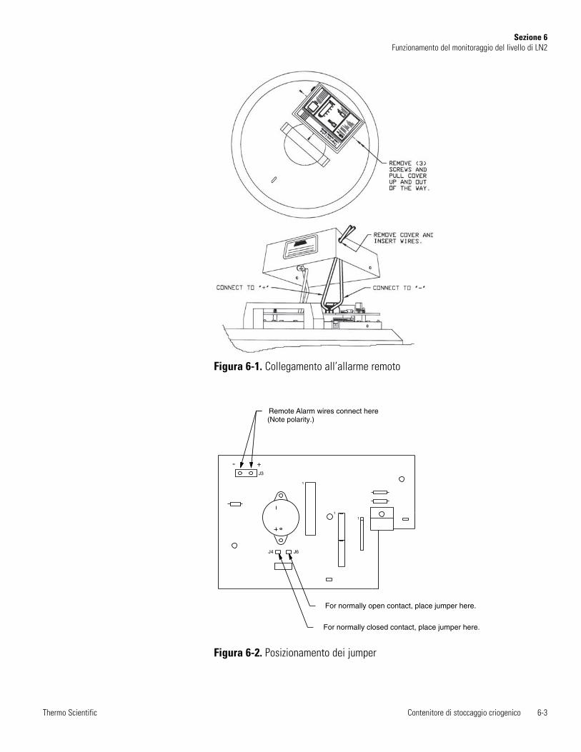
Contenitore di stoccaggio criogenico 6-3Thermo Scientific
Sezione 6Funzionamento del monitoraggio del livello di LN2
1
1
1
For normally closed contact, place jumper here.
For normally open contact, place jumper here.
Remote Alarm wires connect here (Note polarity.)
- +J3
J4 J6
Figura 6-1. Collegamento all’allarme remoto
Figura 6-2. Posizionamento dei jumper
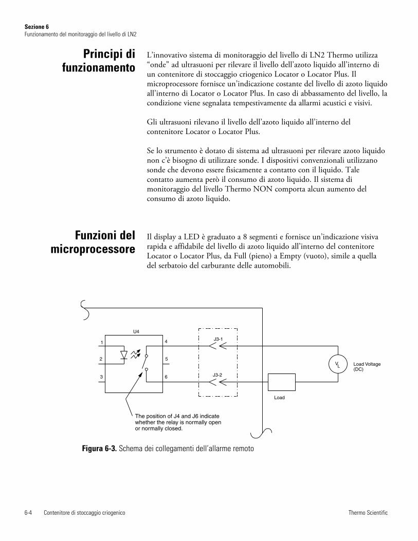
L’innovativo sistema di monitoraggio del livello di LN2 Thermo utilizza“onde” ad ultrasuoni per rilevare il livello dell’azoto liquido all’interno diun contenitore di stoccaggio criogenico Locator o Locator Plus. Ilmicroprocessore fornisce un’indicazione costante del livello di azoto liquidoall’interno di Locator o Locator Plus. In caso di abbassamento del livello, lacondizione viene segnalata tempestivamente da allarmi acustici e visivi.
Gli ultrasuoni rilevano il livello dell’azoto liquido all’interno delcontenitore Locator o Locator Plus.
Se lo strumento è dotato di sistema ad ultrasuoni per rilevare azoto liquidonon c’è bisogno di utilizzare sonde. I dispositivi convenzionali utilizzanosonde che devono essere fisicamente a contatto con il liquido. Talecontatto aumenta però il consumo di azoto liquido. Il sistema dimonitoraggio del livello Thermo NON comporta alcun aumento delconsumo di azoto liquido.
Il display a LED è graduato a 8 segmenti e fornisce un’indicazione visivarapida e affidabile del livello di azoto liquido all’interno del contenitoreLocator o Locator Plus, da Full (pieno) a Empty (vuoto), simile a quelladel serbatoio del carburante delle automobili.
6-4 Contenitore di stoccaggio criogenico Thermo Scientific
Sezione 6Funzionamento del monitoraggio del livello di LN2
Principi difunzionamento
Funzioni delmicroprocessore
Figura 6-3. Schema dei collegamenti dell’allarme remoto
1
2
3 6
5
4
Load
J3-2
J3-1
U4
V Load Voltage(DC)
L
The position of J4 and J6 indicatewhether the relay is normally openor normally closed.

1. L’indicatore “LOW LEVEL” (Livello minimo) lampeggia quandol’azoto liquido scende approssimativamente sotto il livello di 5 cm. Inquesta situazione, il livello dell’azoto liquido è basso ed è necessariorifornire il contenitore al più presto.
2. Un allarme ACUSTICO intermittente segnala che l’azoto liquidoall’interno del contenitore Locator o Locator Plus è scesoapprossimativamente al di sotto del livello di 2,5 cm. La spia “LOWLEVEL” descritta sopra continua a lampeggiare. In questa situazione,l’azoto liquido è pericolosamente basso ed è necessario rifornireimmediatamente il contenitore.
3. Il display a LED a 8 segmenti si accende e, contestualmente, unallarme acustico continuo segnala che il contenitore Locator o LocatorPlus è privo di azoto liquido o che il livello sta scendendo a unavelocità di circa 1,27 cm l’ora. L’allarme segnala quindi una condizionedi emergenza. All’interno del contenitore Locator o Locator Plus si èesaurito l’azoto liquido oppure il livello sta diminuendo rapidamente acausa di un deterioramento del vuoto.
Si accende l’interruttore “RESET” e viene emesso un allarme acusticointermittente se l’operatore non resetta il sistema di monitoraggio dopoaver rimosso il coperchio del contenitore. Il microprocessore deve essereresettato ogni volta che si rimuove il coperchio di Locator o Locator Plus.Prima di rimuovere il coperchio è necessario premere il pulsante RESET,che provoca l’accensione della spia RESET. In modalità reset/pausa, ilsistema di monitoraggio non esegue rilevazioni. Dopo cinque minuti inmodalità di ripristino / Hold, un allarme acustico e remoto attiverà, avvisadi disattivare la modalità di ripristino / Hold quando il coperchio èsostituire sulla nave.
Quando il coperchio con il monitor è stato posto sul recipiente e collegato,attendere circa 15 minuti per il sistema per equilibrare prima di premere iltasto Reset per una misurazione accurata dell'azoto liquido deve essereindicato. Questo processo di equilibrazione si verificherà ogni volta che ilcoperchio viene rimosso. Ogni volta che una nave è aperta o spostata, latemperatura della camera stabilizzata e / o il livello del liquido vieneinterrotto. Il sistema richiede una temperatura stabile e livello liquido perdeterminare un preciso livello di azoto liquido.
Al momento dell’acquisto di Locator o Locator Plus con sistema dimonitoraggio del livello, è necessario attendere almeno 1 giorno prima dicollegare l’unità, affinché l’azoto liquido all’interno del contenitore sistabilizzi. In tal modo si eviteranno falsi allarmi.
Nota Il sistema di monitoraggio del livello può richiedere fino a 10 minutiper stabilire una rilevazione dopo l’applicazione dell’unità sulcriocontenitore o dopo lo spostamento di quest’ultimo. Ricordare dipremere “Reset” dopo aver applicato l’unità sul contenitore. Il LED dicolore verde sull’interruttore deve essere spento.
Contenitore di stoccaggio criogenico 6-5Thermo Scientific
Sezione 6Funzionamento del monitoraggio del livello di LN2
Allarmi acustici evisivi
Funzioni di sicurezza
Funzionamento delmonitoraggio del
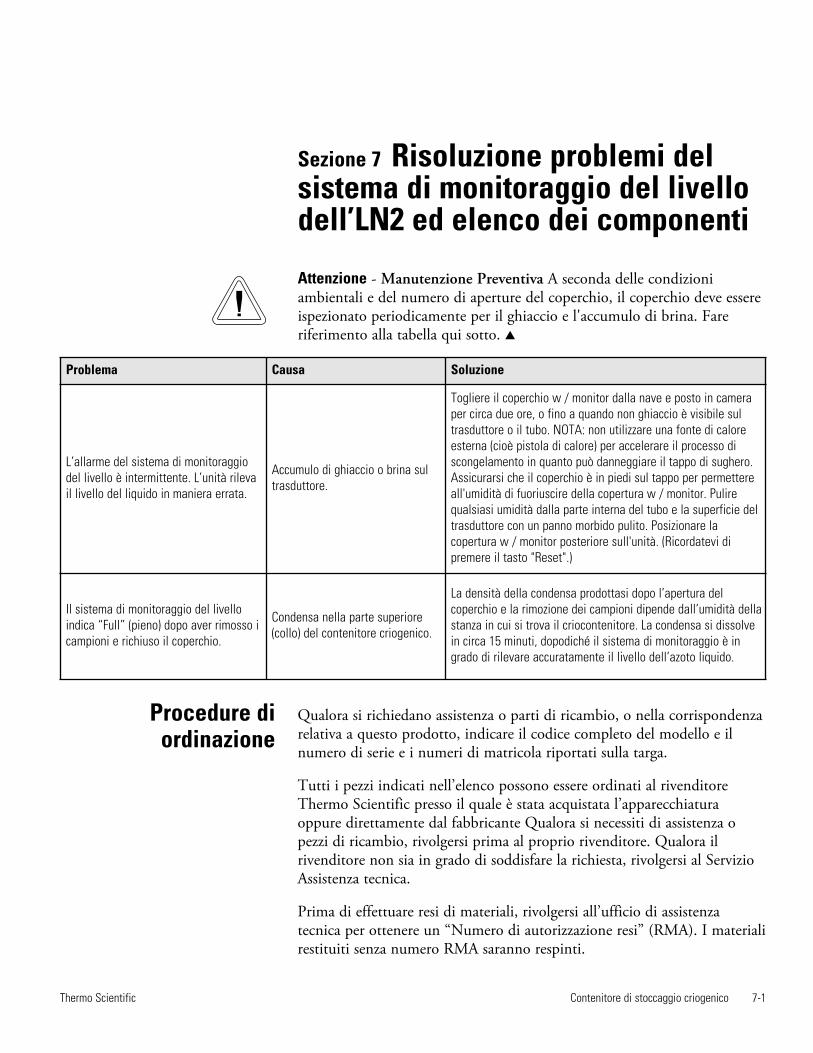
Sezione 7 Risoluzione problemi delsistema di monitoraggio del livellodell’LN2 ed elenco dei componenti
Contenitore di stoccaggio criogenico 7-1Thermo Scientific
Problema Causa Soluzione
L’allarme del sistema di monitoraggiodel livello è intermittente. L’unità rilevail livello del liquido in maniera errata.
Accumulo di ghiaccio o brina sultrasduttore.
Togliere il coperchio w / monitor dalla nave e posto in cameraper circa due ore, o fino a quando non ghiaccio è visibile sultrasduttore o il tubo. NOTA: non utilizzare una fonte di caloreesterna (cioè pistola di calore) per accelerare il processo discongelamento in quanto può danneggiare il tappo di sughero.Assicurarsi che il coperchio è in piedi sul tappo per permettereall'umidità di fuoriuscire della copertura w / monitor. Pulirequalsiasi umidità dalla parte interna del tubo e la superficie deltrasduttore con un panno morbido pulito. Posizionare lacopertura w / monitor posteriore sull'unità. (Ricordatevi dipremere il tasto "Reset".)
Il sistema di monitoraggio del livelloindica “Full” (pieno) dopo aver rimosso icampioni e richiuso il coperchio.
Condensa nella parte superiore(collo) del contenitore criogenico.
La densità della condensa prodottasi dopo l’apertura delcoperchio e la rimozione dei campioni dipende dall’umidità dellastanza in cui si trova il criocontenitore. La condensa si dissolvein circa 15 minuti, dopodiché il sistema di monitoraggio è ingrado di rilevare accuratamente il livello dell’azoto liquido.
Procedure diordinazione
Qualora si richiedano assistenza o parti di ricambio, o nella corrispondenzarelativa a questo prodotto, indicare il codice completo del modello e ilnumero di serie e i numeri di matricola riportati sulla targa.
Tutti i pezzi indicati nell’elenco possono essere ordinati al rivenditoreThermo Scientific presso il quale è stata acquistata l’apparecchiaturaoppure direttamente dal fabbricante Qualora si necessiti di assistenza opezzi di ricambio, rivolgersi prima al proprio rivenditore. Qualora ilrivenditore non sia in grado di soddisfare la richiesta, rivolgersi al ServizioAssistenza tecnica.
Prima di effettuare resi di materiali, rivolgersi all’ufficio di assistenzatecnica per ottenere un “Numero di autorizzazione resi” (RMA). I materialirestituiti senza numero RMA saranno respinti.
Attenzione - Manutenzione Preventiva A seconda delle condizioniambientali e del numero di aperture del coperchio, il coperchio deve essereispezionato periodicamente per il ghiaccio e l'accumulo di brina. Fareriferimento alla tabella qui sotto. s
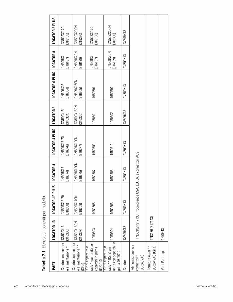
7-2 Contenitore di stoccaggio criogenico Thermo Scientific
Tabe
lla 7
-1. E
lenc
o co
mpo
nent
i per
mod
ello
PART
LO
CATO
R JR
LOCA
TOR
JR P
LUS
LOCA
TOR
4LO
CATO
R 4
PLU
SLO
CATO
R 6
LOCA
TOR
6 PL
US
LOCA
TOR
8LO
CATO
R 8
PLU
S
Copr
ire c
on m
onito
re
alim
enta
zione
*CN
509X
16(3
1630
6)CN
509X
16-7
0(3
1630
8)CN
509X
17(3
1637
4)CN
509X
17-7
0(3
1637
6)CN
509X
15(3
1630
4)CN
509X
15(3
1630
4)CN
509X
7(3
1613
7)CN
509X
7-70
(316
138)
Copr
ire c
on m
onito
re
alim
enta
zione
**
(Cin
a)
CN50
9X16
CN(3
1630
7)
CN50
9X17
CN(3
1630
9)CN
509X
18CN
(316
375)
CN50
9X19
CN(3
1637
7)CN
509X
15CN
(316
305)
CN50
9X15
CN(3
1630
5)CN
509X
7CN
(316
139)
CN50
9X20
CN(3
1639
0)
Kit d
i cop
ertu
ra e
rack
* (p
er u
nità
con
cope
rchi
in p
rima
03/2
010)
1950
503
1950
505
1950
507
1950
509
1950
501
1950
501
CN50
9X7
(316
137)
CN50
9X7-
70(3
1613
8)
Kit d
i cop
ertu
ra e
rack
**
(Cin
a) p
erun
ità c
on c
oper
chi i
npr
ima
03/2
010
1950
504
1950
506
1950
508
1950
510
1950
502
1950
502
CN50
9X7C
N(3
1613
9)CN
509X
20CN
(316
390)
Copr
ireCV
509X
13CV
509X
13CV
509X
13
CV50
9X13
CV
509X
13
CV50
9X13
CV
509X
13
CV50
9X13
Alim
enta
zione
w /
conn
etto
ri*90
-240
VAC
TN50
9X2
(317
133)
*co
mpr
ende
USA
, EU,
UK
e co
nnet
tori
AUS
Forn
itura
ow
er *
*90
-264
VAC
(Cin
a)TN
X136
(317
143)
Vent
Por
t Cap
1950
343
Locator y Locator PlusDepósito criogénico de almacenamiento con o sin monitor de nivel ultrasónicoManual de funcionamiento y lista de piezas
LT509X9 (7018141) Rev. 4
©2010 Thermo Fisher Scientific. Todos los derechos reservados. Impreso en EE.UU.
User M
anual
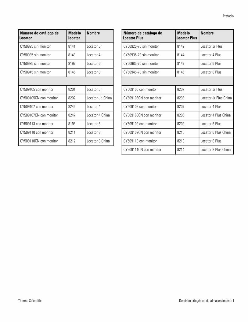
Thermo Scientific
Prefacio
Depósito criogénico de almacenamiento i
Número de catálogo deLocator
ModeloLocator
Nombre
CY50925 sin monitor 8141 Locator Jr
CY50935 sin monitor 8143 Locator 4
CY50985 sin monitor 8197 Locator 6
CY50945 sin monitor 8145 Locator 8
CY509105 con monitor 8201 Locator Jr.
CY509105CN con monitor 8202 Locator Jr. China
CY509107 con monitor 8246 Locator 4
CY509107CN con monitor 8247 Locator 4 China
CY509113 con monitor 8198 Locator 6
CY509110 con monitor 8211 Locator 8
CY509110CN con monitor 8212 Locator 8 China
Número de catálogo deLocator Plus
ModeloLocator Plus
Nombre
CY50925-70 sin monitor 8142 Locator Jr Plus
CY50935-70 sin monitor 8144 Locator 4 Plus
CY50985-70 sin monitor 8147 Locator 6 Plus
CY50945-70 sin monitor 8146 Locator 8 Plus
CY509106 con monitor 8237 Locator Jr Plus
CY509106CN con monitor 8238 Locator Jr Plus China
CY509108 con monitor 8207 Locator 4 Plus
CY509108CN con monitor 8208 Locator 4 Plus China
CY509109 con monitor 8209 Locator 6 Plus
CY509109CN con monitor 8210 Locator 6 Plus China
CY509113 con monitor 8213 Locator 8 Plus
CY509111CN con monitor 8214 Locator 8 Plus China
Thermo Scientificii Depósito criogénico de almacenamiento
Prefacio
Contains Parts and Assemblies
Susceptible to Damage by
Electrostatic Discharge (ESD)
CAUTIONATENCIÓNContiene componentes y
montajes que pueden sufrir dañosprovocados por descargas
electroestáticas (ESD)
Importante Lea este manual de instrucciones. El no leer, entender y seguir las instrucciones en este manual puede resultar en daños a la unidad, lesiones al personal de operación, y el pobre rendimiento del equipo.
Precaución Todos los ajustes y mantenimiento internas deben ser realizadas por personal cualificado.
Precaución Se recomienda tener este buque probado por el fabricante o técnico de servicio cualificadocryovessel cada 7-10 años, independientemente de los problemas (o falta de ella) que haya tenido en elpasado. Esto ayudará a asegurar sus muestras contra la pérdida repentina de nitrógeno líquido debido aun fallo de vacío.
Advertencia De gas nitrógeno puede causar asfixia sin advertencia. Guardar y utilizar el nitrógenolíquido únicamente en un lugar bien ventilado. Como el líquido se evapora, el gas resultante desplaza elaire normal en la zona. (El vapor nebuloso que aparece cuando el nitrógeno líquido se expone al aire es
humedad condensada, no el propio gas. El gas que sale es invisible.) En las zonas cerradas, una cantidadexcesiva de gas de nitrógeno reduce la concentración de oxígeno y puede provocar asfixia. Dado que el gasnitrógeno es incoloro, inodoro e insípido, no puede ser detectada por los sentidos humanos. Respirandouna atmósfera que contiene menos del 19,5% de oxígeno puede causar mareos y provocar rápidamente lapérdida del conocimiento y muerte. Por lo tanto, se recomienda encarecidamente el uso de equipo demonitoreo de oxígeno.
Advertencia Contacto de aviso del nitrógeno líquido con la piel o los ojos puede causar graves(congelación) lesión.
Advertencia No ruede. Siempre mantenga recipiente de nitrógeno líquido en una posición vertical. Tome precauciones para evitar derrames y salpicaduras.
El material contenido en este manual es únicamente con fines informativos. El contenido y el producto quedescribe están sujetos a cambios sin previo aviso. Thermo Fisher Scientific no asume la responsabilidad niofrece garantías con respecto a este manual. En ningún caso Thermo se hace responsable de los daños,directos o incidentales, que surja de o relacionada con el uso de este manual.
Uso previsto:Los recipientes de almacenamiento criogénico Thermo Fisher Scientific están destinados a almacenarmuestras biológicas a temperaturas criogénicas. Estos productos están compuestos de un recipiente y unatapa, con o sin un monitor de nivel.
El uso no intencional:Estos productos no están destinados para su uso en el entorno del paciente.
Cuando este manual está traducido a otros idiomas, la versión de EE.UU. Inglés es vinculante.
Thermo Scientific Depósito criogénico de almacenamiento iii
Prefacio
Instrucciones de funcionamiento y de mantenimiento importantes. Lea atentamente el texto adjunto.
Posible riesgo de descarga eléctrica. Solo personas cualificadas deben realizar los procedimientosasociados a este símbolo.
Peligros por temperaturas extremas. Solo personas cualificadas deben realizar los procedimientosasociados a este símbolo.
Posibles riesgos biológicos. Deben utilizarse los equipos y procedimientos de protección adecuados.
Señalización de los equipos eléctricos y electrónicos, aplicable a los equipos eléctricos y electrónicosamparados por la Directiva 2002/96/CE (RAEE) y el equipo que se ha comercializado después del 13 de agosto de 2005
Este producto está obligado a cumplir con la Directiva de la Unión Europea sobre residuos de aparatoseléctricos y electrónicos (RAEE) 2002/96CE. Está marcado con el símbolo RAEE. Thermo FisherScientific ha contratado a al menos una empresa de reciclado/desecho de residuos en cada estadomiembro de la UE, y este producto debe reciclarse o desecharse a través de dichas empresas. Enwww.thermofisher.com podrá obtener más información sobre el cumplimiento de Thermo con estadirectiva y las empresas de reciclado presentes en su país, así como información sobre productosThermo.
4 Utilice siempre el equipo de protección adecuado (ropa, guantes, gafas de seguridad, etc.).
4 Disipe siempre el frío o el calor extremo y utilice ropa de protección.
4 Respete siempre unas buenas prácticas higiénicas.
4 Cada persona es responsable de su propia seguridad.
Thermo Scientificiv Depósito criogénico de almacenamiento
Prefacio
¿Necesita información o asistencia acercade los productos Thermo Fisher Scientific?
Le rogamos que se ponga en contacto con nosotros a través de:
América del Norte: EEUU +1-866-984-3766, Canadá +1-905-332-2000.Europa: Bélgica +32 2 482 30 30, Dinamarca +45 4 166 200, Finlandia +358 9 329 100, Francia +33 2 28 03 20 00,Alemania / Austria / Suiza +49 6103 4081012, Italia +39-02-2511141, Países Bajos +31 76 571 4440,Rusia / CIS +7 095 755 9045, España / Portugal +34 93 2233154, Suecia +46 8 742 03 90,Reino Unido / Irlanda +44 870 609 9203.Asia: China +86 21 5424 1582, India +91 22 2778 1101, Japón +81 45 453 9220,Resto de países asiáticos +86 2885 4613.América del Sur y países no mencionados: +33 2 2803 2000
Nuestro personal de ventas puede proporcionarle información acerca de los precios yofrecerle presupuestos. Podemos recoger su pedido y facilitarle información sobre la entregade equipos especializados o establecer acuerdos para que nuestro representante más cercanole pueda contactar. Nuestros productos están expuestos en Internet y nos podrá contactar através de nuestra página web.
Nuestro personal de servicio técnico puede proporcionarle información técnica sobrela correcta instalación, el funcionamiento o los problemas de su equipo. Tambiénpodemos facilitarle piezas de recambio u ofrecerle un servicio in situ. Asimismo, lepodemos proporcionar un presupuesto sobre nuestra Garantía Extendida para susproductos Thermo Scientific.
Cualquiera de los productos Thermo Scientific que necesite o que use, estaremos encantadosde analizar sus aplicaciones. Si advierte problemas técnicos, trabajando de forma conjunta, leayudaremos a ubicar el problema y, si es posible, ayudar a que lo solucione usted mismo porel teléfono sin necesidad de una llamada de servicio.
Cuando sea necesario un servicio más exhaustivo, le ayudaremos con técnicos formadosdirectamente en fábrica o mediante una organización de asistencia técnica experimentada para unareparación en el acto. Si sus necesidades técnicas están cubiertas por la garantía, nos aseguraremosde que la reparación de la unidad corra a cuenta nuestra y de que quede satisfecho.
Depósito criogénico de almacenamiento vThermo Scientific
Índice
Información sobre seguridad . . . . . . . . . . . . . . . . . . . . . . . . . . . . . . . . . .1-1Consulte . . . . . . . . . . . . . . . . . . . . . . . . . . . . . . . . . . . . . . . . . . . . . .1-1Utilización general . . . . . . . . . . . . . . . . . . . . . . . . . . . . . . . . . . . . . . .1-1Advertencias . . . . . . . . . . . . . . . . . . . . . . . . . . . . . . . . . . . . . . . . . . . .1-2Precauciones . . . . . . . . . . . . . . . . . . . . . . . . . . . . . . . . . . . . . . . . . . . .1-2
Características técnicas generales . . . . . . . . . . . . . . . . . . . . . . . . . . . .2-1Condiciones medioambientales . . . . . . . . . . . . . . . . . . . . . . . . . . . . .2-1
Desempaquetado . . . . . . . . . . . . . . . . . . . . . . . . . . . . . . . . . . . . . . . . . . . . .3-1
Funcionamiento . . . . . . . . . . . . . . . . . . . . . . . . . . . . . . . . . . . . . . . . . . . . . .4-1Medición de la cantidad de nitrógeno líquido . . . . . . . . . . . . . . . . . .4-1Condiciones de limpieza generales . . . . . . . . . . . . . . . . . . . . . . . . . . .4-2Almacenamiento de muestras en fase de vapor . . . . . . . . . . . . . . . . . .4-2Precauciones . . . . . . . . . . . . . . . . . . . . . . . . . . . . . . . . . . . . . . . . . . . .4-2
Piezas de repuesto . . . . . . . . . . . . . . . . . . . . . . . . . . . . . . . . . . . . . . . . . . .5-1
Funcionamiento del monitor de nivel de nitrógeno líquido . . . . . . . .6-1Instalación . . . . . . . . . . . . . . . . . . . . . . . . . . . . . . . . . . . . . . . . . . . . .6-1Alarma remota . . . . . . . . . . . . . . . . . . . . . . . . . . . . . . . . . . . . . . . . . .6-1Especificaciones de contacto de alarmas . . . . . . . . . . . . . . . . . . . . . . .6-2Funciones de microprocesador . . . . . . . . . . . . . . . . . . . . . . . . . . . . . .6-4Principios de funcionamiento . . . . . . . . . . . . . . . . . . . . . . . . . . . . . . .6-4Funcionamiento del monitor de nivel . . . . . . . . . . . . . . . . . . . . . . . .6-5Función de seguridad . . . . . . . . . . . . . . . . . . . . . . . . . . . . . . . . . . . . .6-5Alarmas sonoras y visuales . . . . . . . . . . . . . . . . . . . . . . . . . . . . . . . . .6-5
Resolución de problemas del monitor de nivel LN2 y lista de piezas . .7-1Procedimientos para la realización de pedidos . . . . . . . . . . . . . . . . . .7-2
Sección 1
Sección 2
Sección 3
Sección 4
Sección 5
Sección 6
Sección 7
Depósito criogénico de almacenamiento 1-1Thermo Scientific
Consulte
Sección 1 Información sobre seguridad
Este manual contiene información importante sobre seguridad y funciona -miento. El usuario debe leer atentamente y entender el contenido de estemanual antes de utilizar el equipo.
Su depósito criogénico Thermo Scientific ha sido diseñado teniendo encuenta el funcionamiento, la fiabilidad y la seguridad. Es responsabilidaddel usuario instalarlo de acuerdo con las normativas eléctricas locales. Paraque funcione de manera segura, preste atención a las Advertencias,Precauciones y Notas que aparecen por todo el manual.
Todos los depósitos de crioconservación, independientemente delfabricante, utilizan vacío para poder ofrecer las elevadas propiedades deaislamiento necesarias para mantener el nitrógeno en estado líquido. Enrealidad, son muy similares a los depósitos Thermos® que se utilizan paramantener café, sopa o leche.
¿Recuerda lo frágiles que son? Dado que el vacío no es perfecto y no puededurar eternamente, recomendamos que supervise periódicamente elconsumo de nitrógeno líquido que utiliza el depósito, por ejemplo, cada 1-2 días. De este modo, podrá anticipar los sutiles cambios de consumo yprever los problemas. Puede optar por utilizar un monitor de nivel paraeste fin (consulte la página 6-1 para obtener información sobre elfuncionamiento del monitor de nivel).
Además, si las muestras son muy delicadas, únicas o irreemplazables,recomendamos colocarlas en dos depósitos diferentes. Recuerde que no esaconsejable poner todos los huevos en la misma cesta…
Por último, dado que el vacío no dura eternamente, pida al fabricante deldepósito o a un técnico cualificado en criodepósitos que revise su unidadcada 7-10 años, independientemente de los problemas (o la ausencia deellos) que haya tenido en el pasado. Esto asegurará las muestras anteposibles pérdidas repentinas de nitrógeno como consecuencia de un fallodel vacío.
No utilice este producto para un fin diferente al que fue concebido.
Si utiliza el equipo de un modo distinto al especificado por el fabricantepuede alterar la protección proporcionada por el equipo.
Uso general
1-2 Depósito criogénico de almacenamiento Thermo Scientific
Sección 1Información sobre seguridad
• Esta unidad está diseñada para ser utilizada por personal cualificadoen un entorno con buena ventilación.
• El nitrógeno líquido está extremadamente frío; hierve a -196 °C.
• Respete todas las indicaciones de precaución y advertencia necesariasrelacionadas con riesgos como congelación, quemadura por contacto,asfixia, etc., en la zona criogénica.
• Para evitar lesiones como consecuencia de congelación o viales rotos,extreme las precauciones al manipular nitrógeno líquido, alalmacenarlo o al desplazar los recipientes o cualquier otro objeto quehaya estado en contacto con esta sustancia.
• No deje zonas de la piel expuestas.
• Utilice el equipo de protección personal donde sea necesario;protección para la cara, guantes criogénicos y delantal criogénico.
• No selle herméticamente los contenedores de nitrógeno líquido niimpida que se escape el gas de nitrógeno.
• Manipule siempre las ampollas con pinzas. Pueden explotar al sacarlasdel depósito.
• Extreme la precaución para evitar que salpique o se derrame nitrógenolíquido durante el traslado y la extracción del contenido y los soportesde almacenamiento.
• Retire inmediatamente cualquier prenda o equipo de seguridad sobreel que haya salpicado nitrógeno líquido.
• Consiga asistencia médica inmediatamente en caso de sufrir lesionespor congelación a causa del nitrógeno líquido.
Advertencias
• Utilice solo la fuente de alimentación proporcionada por la unidad.
• No llene los depósitos de nitrógeno líquido en exceso. El nivel denitrógeno líquido nunca debe situarse por encima de las partessuperiores de las rejillas situadas en el interior del depósito. El pesoexcesivo puede romper el cuello y provocar un fallo del vacío.
• Al introducir o retirar rejillas, tenga cuidado de no entrar en contactocon la zona del tubo de cuello del depósito. Retire o inserte las rejillaslentamente y en vertical. Los arañazos en la zona del tubo de cuellopueden provocar un fallo prematuro del vacío.
• No altere ni extraiga el puerto de vacío (cubierto por un tapón deplástico negro en el lateral del depósito); esto anulará la garantía.
• No derrame nitrógeno líquido en el puerto de vacío; esto provocará unfallo en el vacío.
• Mantenga siempre el recipiente con nitrógeno líquido en posiciónvertical.
• No utilice este depósito Locator para realizar el transporte.
Depósito criogénico de almacenamiento 1-3Thermo Scientific
Sección 1Título de sección
Precauciones
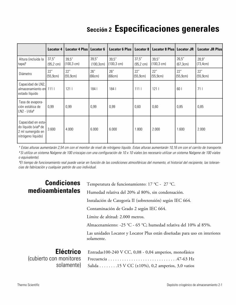
Depósito criogénico de almacenamiento 2-1Thermo Scientific
Sección 2 Especificaciones generales
Temperatura de funcionamiento: 17 °C - 27 °C.
Humedad relativa del 20% al 80%, sin condensación.
Instalación de Categoría II (sobretensión) según IEC 664.
Contaminación de Grado 2 según IEC 664.
Límite de altitud: 2.000 metros.
Almacenamiento: -25 °C - 65 °C; humedad relativa del 10% al 85%.
Las unidades Locator y Locator Plus están diseñadas para uso en interioressolamente.
Locator 4 Locator 4 Plus Locator 6 Locator 6 Plus Locator 8 Locator 8 Plus Locator JR Locator JR Plus
Altura (incluida latapa)1
37,5” (95,2 cm)
39,5” (100,3 cm)
39,5”(100,3cm)
39,5” (100,3 cm)
37,5” (95,2 cm)
39,5” (100,3 cm)
26,5” (67,3cm)
28,9” (73,4cm)
Diámetro 22”(55,9cm)
22” (55,9cm)
26” (66cm)
26” (66cm)
22”(55,9cm)
22” (55,9cm)
22” (55,9cm)
22” (55,9cm)
Capacidad de LN2,almacenamiento enestado líquido
111 l 121 l 184 l 184 l 111 l 121 l 60 l 71 l
Tasa de evapora-ción estática deLN2 - l/día3
0,99 0,99 0,99 0,99 0,60 0,60 0,85 0,85
Capacidad en esta-do líquido (vial2 de2 ml sumergido ennitrógeno líquido)
3.600 4.000 6.000 6.000 1.800 2.000 1.600 2.000
1 Estas alturas aumentarán 2,54 cm con el monitor de nivel de nitrógeno líquido. Estas alturas aumentarán 10,16 cm con el carrito de transporte.2 Si utiliza un sistema Nalgene de 100 criocajas con una configuración de 10 x 10 viales (es necesario utilizar un sistema Nalgene de 100 vialeso equivalente).3El tiempo de funcionamiento real puede variar en función de las condiciones atmosféricas del momento, el historial del recipiente, las toleran-cias de fabricación y cualquier patrón de uso individual.
Condicionesmedioambientales
Eléctrico (cubierto con monitores
solamente)
Entradas100-240 V CC, 0,08 - 0,04 amperios, monofásicoFrecuencia . . . . . . . . . . . . . . . . . . . . . . . . . . . . . .47-63 HzSalida . . . . . . . .15 V CC (±10%), 0,2 amperios, 3,0 vatios
Depósito criogénico de almacenamiento 3-1Thermo Scientific
Sección 3 Desempaquetado
Antes de usar su nuevo depósito Locator o Locator Plus, revíselo minucio -samente. Compruebe que no haya signos de daños que puedan haberseproducido durante el envío. Es aconsejable llenar (consulte las instruccionesde llenado) todas las unidades nuevas con nitrógeno líquido y comprobarla tasa de pérdida de nitrógeno líquido durante unos días. Si hay algúnproblema, póngase en contacto con el Servicio de atención al cliente loantes posible.
La tarjeta de registro de la garantía que se adjunta al depósito deberellenarse y devolverse a la fábrica en un plazo de 30 días para activar lagarantía. Esta información debe incluir el número de serie que se encuentraen la etiqueta del depósito.
Nota: La causa más habitual de avería de los depósitos de almacenamientode nitrógeno líquido es el fallo mecánico. El tubo de cuello del recipientesoporta todo el peso de la carcasa interior y el nitrógeno líquido quecontiene. Un soplado en los lados o en las esquinas provoca que la carcasainterior realice un movimiento pendular, lo que daña el tubo de cuello.Cualquier depósito de almacenamiento que haya estado expuesto a unaccidente, se haya caído o haya sufrido algún golpe en una esquina tenderáa fallar más rápidamente que otro que no haya sufrido estos problemas.
Precaución: Extreme las precauciones al mover el depósito Locator oLocator Plus. Los sistemas de almacenamiento criobiológicos Locator yLocator Plus no son depósitos de transporte. Los carritos de transporteestán diseñados para llevar a cabo las tareas de desplazamiento dentro dellaboratorio o de un laboratorio a otro solamente. Si traslada los depósitoscompletos y recorren largas distancias, pasando sobre las grietas del suelo,por umbrales, rampas pronunciadas o ascensores, puede producirse un falloprematuro del vacío. Evite el uso excesivo de la fuerza al mover buque; esto puede causar vuelco, lo que resulta en daños y/o derrame de nitrógeno líquido.
Nota: Si es necesario transportar las muestras en condiciones criogénicas,utilice la línea de unidades de transporte en seco Arctic Express de ThermoScientific.
Depósito criogénico de almacenamiento 4-1Thermo Scientific
Sección 4 Funcionamiento
Precaución: No llene el depósito Locator o Locator Plus de nitrógenolíquido en exceso. El nivel de nitrógeno líquido del depósito (con lasrejillas instaladas) nunca debe sobrepasar los 50 cm (20 pulgadas) en elcaso de Locator 4 y Locator 8, los 25 cm (10 pulgadas) en el caso deLocator Jr., los 55,8 cm (22 pulgadas) en el caso de Locator 4, 6, y 8 Plusy los 30,5 cm (12 pulgadas) en el caso de Locator Jr. Plus. Si llena eldepósito hasta la parte inferior del tubo de cuello o por encima de estazona, puede producirse un fallo inmediato o prematuro del vacío. s
Precaución: Al introducir o retirar las rejillas, procure no entrar encontacto con la zona del tubo de cuello del depósito. Retire o inserte lasrejillas lentamente y en vertical. Los arañazos en el área del tubo de cuellopueden provocar un fallo prematuro del vacío. s
Precaución: No derrame nitrógeno líquido en el puerto de vacío (cubiertopor un tapón de plástico negro en el lado del depósito). Esto puedeprovocar un fallo del vacío. s
Para evitar que el depósito criogénico de almacenamiento Locator oLocator Plus pueda sufrir daños que puedan provocar una pérdida de vacíoprematura, es importante utilizar el siguiente procedimiento al verternitrógeno líquido en un depósito tibio.
1. Vierta solo una pequeña cantidad de nitrógeno líquido (5-10 litros) enun depósito nuevo o tibio.
2. Deje que esta pequeña cantidad de nitrógeno líquido se asiente en eldepósito tapado durante al menos 2 horas. Así se limitará la tensióngenerada por el cambio repentino de temperatura que se produce alañadir nitrógeno líquido a un depósito tibio.
3. Añada otros 15 litros de nitrógeno líquido al depósito.
4. Deje que el depósito se asiente durante 48 horas y supervise elconsumo de nitrógeno líquido con una varilla de madera, un medidorsumergible opcional (nº de pieza 180143) o un monitor de nivel.
5. Siga las instrucciones para llenar la unidad Locator o Locator Plus(consulte el apartado Precaución de esta sección). Deje un espacio parael desplazamiento del nitrógeno líquido cuando se introduzcan lasrejillas y las cajas.
6. Introduzca y retire las rejillas lentamente. Deje que salga el nitrógenolíquido por las cajas y las rejillas.
Instrucciones de llenado
4-2 Depósito criogénico de almacenamiento Thermo Scientific
Sección 4Funcionamiento
1. Utilice una varilla de madera o un medidor sumergible opcional (nº depieza 180143) para medir el nivel del nitrógeno líquido. NO utiliceNUNCA un tubo hueco o una varilla de plástico para medir el nivel denitrógeno líquido.
2. El nivel quedará indicado por la línea de escarcha que se forma alretirar la varilla.
3. Se puede utilizar un monitor de nivel para realizar medicionesconstantes. Consulte la Sección 6.
1. Retire las dos criocajas inferiores de cada rejilla.
2. Mida la altura de las 2 criocajas apiladas una sobre otra.
3. Llene el depósito de nitrógeno líquido hasta la altura obtenida en elpaso 2. Utilice una varilla para medir el nivel de líquido del depósito.
4. Coloque las rejillas en el depósito sin las dos criocajas inferiores. Lasmuestras están ahora por encima del nitrógeno líquido y se almacenanen fase de vapor.
Importante: Siempre debe utilizarse un monitor de nivel al almacenar lasmuestras en la fase de vapor, debido a los niveles ya bajos del nitrógenolíquido. Consulte la Sección 5 para conocer el monitor de nivel adecuadopara su sistema. s
Limpie las superficies exteriores con un trapo ligeramente humedecido enuna solución jabonosa suave.
Almacenamiento de muestras en fase
de vapor
Condiciones delimpieza generales
Medición de la cantidad de
nitrógeno líquido
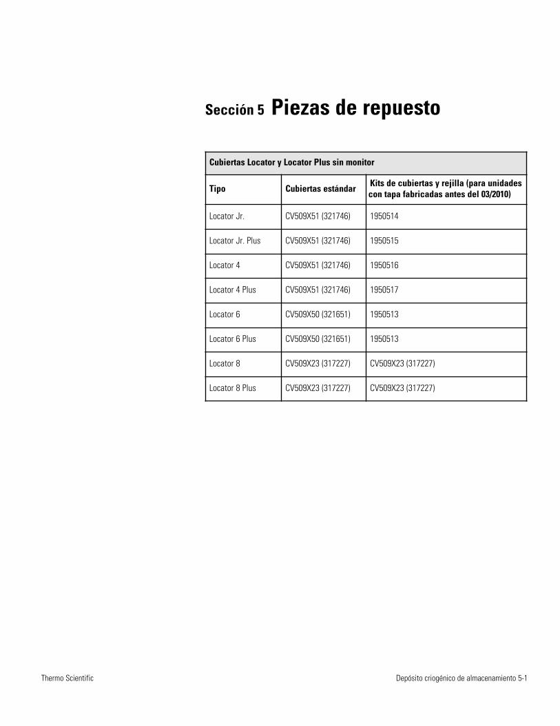
Depósito criogénico de almacenamiento 5-1Thermo Scientific
Sección 5 Piezas de repuesto
Cubiertas Locator y Locator Plus sin monitor
Tipo Cubiertas estándar Kits de cubiertas y rejilla (para unidadescon tapa fabricadas antes del 03/2010)
Locator Jr. CV509X51 (321746) 1950514
Locator Jr. Plus CV509X51 (321746) 1950515
Locator 4 CV509X51 (321746) 1950516
Locator 4 Plus CV509X51 (321746) 1950517
Locator 6 CV509X50 (321651) 1950513
Locator 6 Plus CV509X50 (321651) 1950513
Locator 8 CV509X23 (317227) CV509X23 (317227)
Locator 8 Plus CV509X23 (317227) CV509X23 (317227)
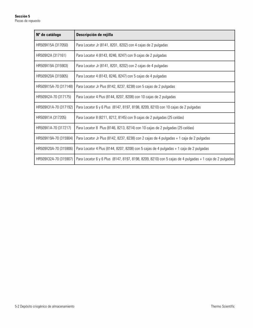
5-2 Depósito criogénico de almacenamiento Thermo Scientific
Sección 5Piezas de repuesto
Nº de catálogo Descripción de rejilla
HR509X15A (317050) Para Locator Jr (8141, 8201, 8202) con 4 cajas de 2 pulgadas
HR509X2A (317161) Para Locator 4 (8143, 8246, 8247) con 9 cajas de 2 pulgadas
HR509X19A (315903) Para Locator Jr (8141, 8201, 8202) con 2 cajas de 4 pulgadas
HR509X20A (315905) Para Locator 4 (8143, 8246, 8247) con 5 cajas de 4 pulgadas
HR509X15A-70 (317148) Para Locator Jr Plus (8142, 8237, 8238) con 5 cajas de 2 pulgadas
HR509X2A-70 (317175) Para Locator 4 Plus (8144, 8207, 8208) con 10 cajas de 2 pulgadas
HR509X31A-70 (317192) Para Locator 6 y 6 Plus (8147, 8197, 8198, 8209, 8210) con 10 cajas de 2 pulgadas
HR509X1A (317205) Para Locator 8 (8211, 8212, 8145) con 9 cajas de 2 pulgadas (25 celdas)
HR509X1A-70 (317217) Para Locator 8 Plus (8146, 8213, 8214) con 10 cajas de 2 pulgadas (25 celdas)
HR509X19A-70 (315904) Para Locator Jr Plus (8142, 8237, 8238) con 2 cajas de 4 pulgadas + 1 caja de 2 pulgadas
HR509X20A-70 (315906) Para Locator 4 Plus (8144, 8207, 8208) con 5 cajas de 4 pulgadas + 1 caja de 2 pulgadas
HR509X32A-70 (315907) Para Locator 6 y 6 Plus (8147, 8197, 8198, 8209, 8210) con 5 cajas de 4 pulgadas + 1 caja de 2 pulgadas
Sección 6 Funcionamiento del monitorde nivel de nitrógeno líquido
El monitor de nivel de nitrógeno líquido (LN2) ofrece una indicaciónconstante del nivel de LN2 e informa mediante alarmas visuales y sonorascuando el nivel es bajo. Le avisa cuando es necesario llenar el depósito. Elmonitor de nivel se envía montado directamente en la cubiertacorrespondiente de Locator o Locator Plus. Puede conectarse a un sistemade alarma remota para advertirle de los problemas cuando no se encuentreen el laboratorio. Este equipo ha sido diseñado para funcionar con unafuente de alimentación externa proporcionada por el fabricante. Estádiseñado para ser utilizado solamente con los depósitos de LN2 de ThermoScientific.
Precaución: Utilice este producto únicamente para el fin para el que hasido diseñado. s
Advertencia: Posible riesgo de descarga eléctrica. Solo personas cualificadasdeben llevar a cabo los procedimientos asociados con este símbolo. s
Nota Si el monitor de nivel fue adquirido como parte de un sistemaLocator o Locator Plus, continúe en el paso 3. Si es un accesorio para unsistema Locator o Locator Plus existente, comience por el paso 1. s
1. Saque de la caja el monitor de nivel y la cubierta de Locator o LocatorPlus.
2. Retire la cubierta presente en el Locator o Locator Plus y sustitúyalapor el nuevo monitor de nivel y su cubierta.
3. Revise las especificaciones eléctricas de la fuente de alimentación paraconocer los datos eléctricos y conecte la unidad a una tomadebidamente conectada a tierra.
Depósito criogénico de almacenamiento 6-1Thermo Scientific
Instalación
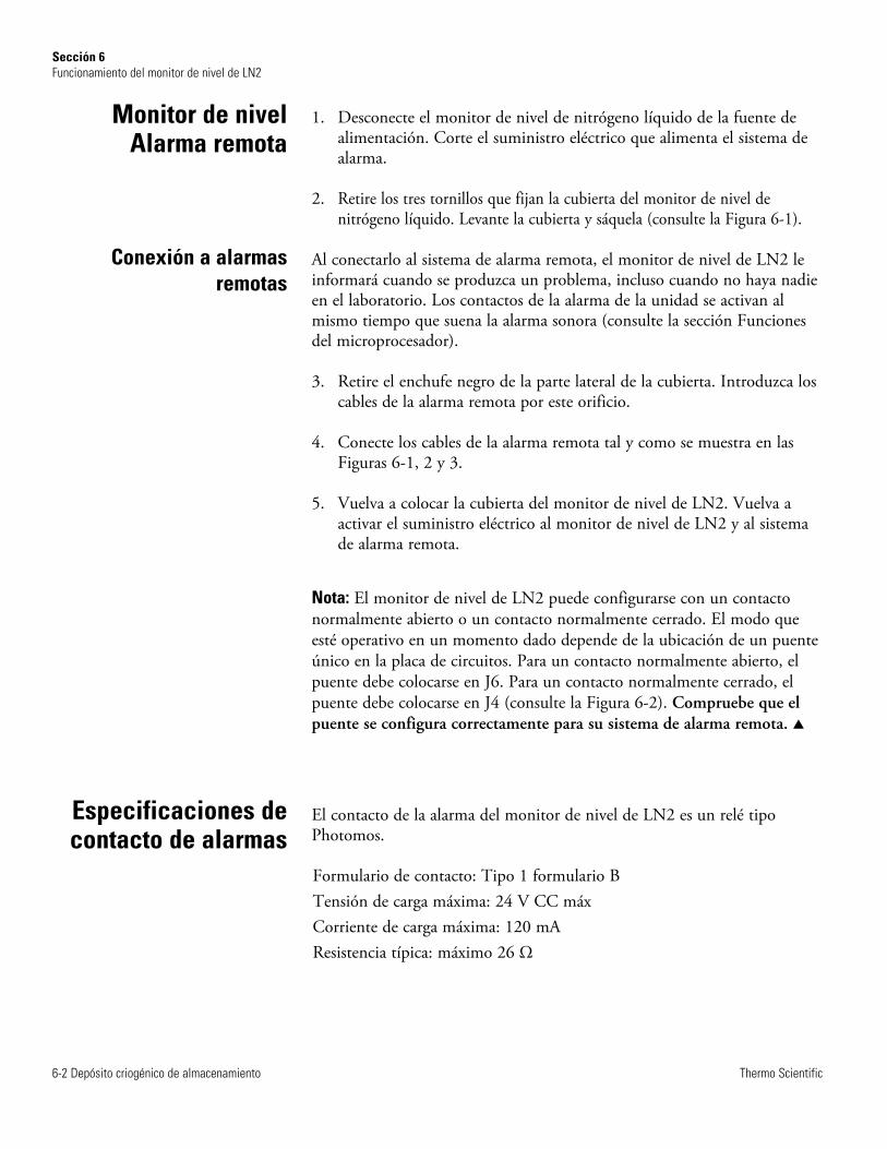
1. Desconecte el monitor de nivel de nitrógeno líquido de la fuente dealimentación. Corte el suministro eléctrico que alimenta el sistema dealarma.
2. Retire los tres tornillos que fijan la cubierta del monitor de nivel denitrógeno líquido. Levante la cubierta y sáquela (consulte la Figura 6-1).
Al conectarlo al sistema de alarma remota, el monitor de nivel de LN2 leinformará cuando se produzca un problema, incluso cuando no haya nadieen el laboratorio. Los contactos de la alarma de la unidad se activan almismo tiempo que suena la alarma sonora (consulte la sección Funcionesdel microprocesador).
3. Retire el enchufe negro de la parte lateral de la cubierta. Introduzca loscables de la alarma remota por este orificio.
4. Conecte los cables de la alarma remota tal y como se muestra en lasFiguras 6-1, 2 y 3.
5. Vuelva a colocar la cubierta del monitor de nivel de LN2. Vuelva aactivar el suministro eléctrico al monitor de nivel de LN2 y al sistemade alarma remota.
Nota: El monitor de nivel de LN2 puede configurarse con un contactonormalmente abierto o un contacto normalmente cerrado. El modo queesté operativo en un momento dado depende de la ubicación de un puenteúnico en la placa de circuitos. Para un contacto normalmente abierto, elpuente debe colocarse en J6. Para un contacto normalmente cerrado, elpuente debe colocarse en J4 (consulte la Figura 6-2). Compruebe que elpuente se configura correctamente para su sistema de alarma remota. s
El contacto de la alarma del monitor de nivel de LN2 es un relé tipoPhotomos.
Formulario de contacto: Tipo 1 formulario BTensión de carga máxima: 24 V CC máx Corriente de carga máxima: 120 mA Resistencia típica: máximo 26 Ω
6-2 Depósito criogénico de almacenamiento Thermo Scientific
Sección 6Funcionamiento del monitor de nivel de LN2
Especificaciones decontacto de alarmas
Monitor de nivel Alarma remota
Conexión a alarmasremotas
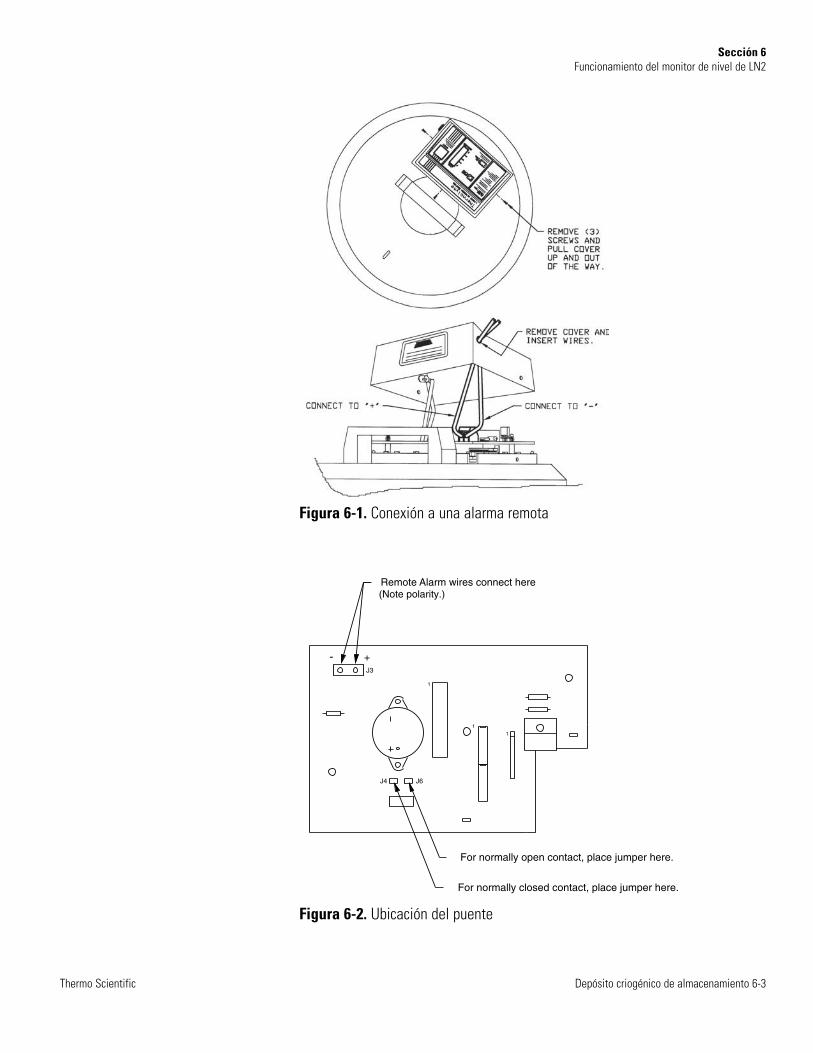
Depósito criogénico de almacenamiento 6-3Thermo Scientific
Sección 6Funcionamiento del monitor de nivel de LN2
1
1
1
For normally closed contact, place jumper here.
For normally open contact, place jumper here.
Remote Alarm wires connect here (Note polarity.)
- +J3
J4 J6
Figura 6-1. Conexión a una alarma remota
Figura 6-2. Ubicación del puente
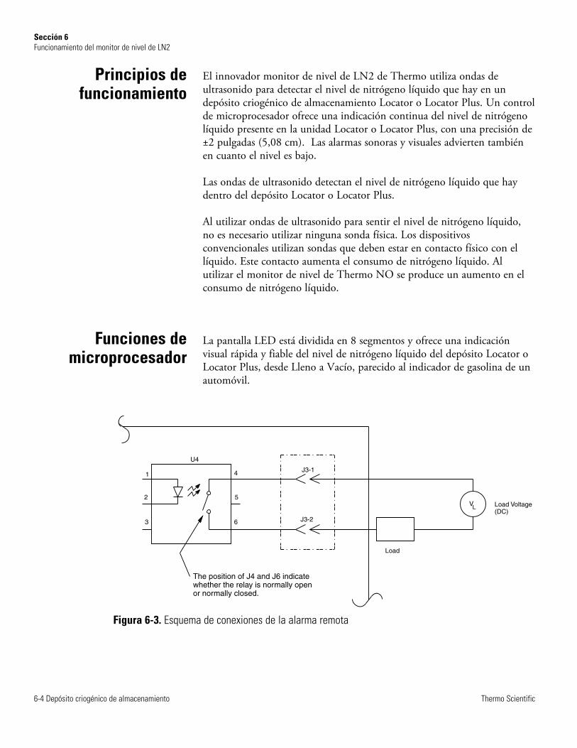
El innovador monitor de nivel de LN2 de Thermo utiliza ondas deultrasonido para detectar el nivel de nitrógeno líquido que hay en undepósito criogénico de almacenamiento Locator o Locator Plus. Un controlde microprocesador ofrece una indicación continua del nivel de nitrógenolíquido presente en la unidad Locator o Locator Plus, con una precisión de±2 pulgadas (5,08 cm). Las alarmas sonoras y visuales advierten tambiénen cuanto el nivel es bajo.
Las ondas de ultrasonido detectan el nivel de nitrógeno líquido que haydentro del depósito Locator o Locator Plus.
Al utilizar ondas de ultrasonido para sentir el nivel de nitrógeno líquido,no es necesario utilizar ninguna sonda física. Los dispositivosconvencionales utilizan sondas que deben estar en contacto físico con ellíquido. Este contacto aumenta el consumo de nitrógeno líquido. Alutilizar el monitor de nivel de Thermo NO se produce un aumento en elconsumo de nitrógeno líquido.
La pantalla LED está dividida en 8 segmentos y ofrece una indicaciónvisual rápida y fiable del nivel de nitrógeno líquido del depósito Locator oLocator Plus, desde Lleno a Vacío, parecido al indicador de gasolina de unautomóvil.
6-4 Depósito criogénico de almacenamiento Thermo Scientific
Sección 6Funcionamiento del monitor de nivel de LN2
Principios defuncionamiento
Funciones demicroprocesador
Figura 6-3. Esquema de conexiones de la alarma remota
1
2
3 6
5
4
Load
J3-2
J3-1
U4
V Load Voltage(DC)
L
The position of J4 and J6 indicatewhether the relay is normally openor normally closed.
1. La luz del indicador “NIVEL BAJO” se enciende de manera continuadacuando el nivel de nitrógeno líquido está por debajo del nivel de 2pulgadas (5,08 cm) aproximadamente. En este caso, el nivel de nitró -geno líquido es bajo y se le informa de que debe llenar el depósito loantes posible.
2. Se activa una alarma remota y SONORA de forma continuada cuandoel nitrógeno líquido se encuentre por debajo del nivel de 1 pulgada(2,54 cm) aproximadamente del interior del depósito Locator oLocator Plus, además la luz “NIVEL BAJO” seguirá parpadeando. Eneste caso, el nivel del nitrógeno líquido es peligrosamente bajo y se leinforma de que debe rellenar el depósito inmediatamente.
3. Las alarmas remotas y SONORAS se activan de forma continuada y lapantalla LED de 8 secciones y las luces “NIVEL BAJO” parpadeanpara indicar un caso de emergencia. Esta situación de alarma seproduce cuando el depósito Locator o Locator Plus no tenga nitrógenolíquido o el monitor tenga un error y sea incapaz de detectar niveles deLN2.
Es necesario reiniciar el microprocesador cada vez que se retire la cubiertadel Locator o Locator Plus. Antes de retirar la cubierta, pulse el botónRESET (reiniciar). Se iluminará la luz RESET (reiniciar). En este modoReset/Hold (reiniciar/mantener), el monitor no realiza detección alguna.Después de cinco minutos en el modo Reset/Hold, se activará una alarmaremota y sonora, que le informa de que debe desactivar el modoReset/Hold cuando se vuelva a colocar la cubierta en el depósito.
Una vez que se haya colocado la cubierta con el monitor y se hayaconectado, espere unos 15 minutos a que el sistema se equilibre antes depulsar el botón Reset para que se produzca una medición precisa delnitrógeno líquido. Este proceso de equilibrado se producirá cada vez que seretire la cubierta. Cada vez que se abra o mueva el depósito, se alterará latemperatura de la cámara y/o el nivel de líquido estabilizados. El sistemanecesita que haya una temperatura y un nivel de líquido estables paradeterminar el nivel exacto de nitrógeno líquido.
Si acaba de adquirir un nuevo Locator o Locator Plus junto con sumonitor, deje pasar al menos 1 día para que se equilibre el nitrógenolíquido del depósito antes de conectar la unidad. Así evitará falsas alarmas.
Nota: El monitor de nivel puede tardar hasta 10 minutos en ofrecer unalectura después de instalar la unidad en un criodepósito, o después dehaber trasladado el criodepósito en cuestión. Recuerde pulsar el botón“Reset” después de situar la unidad en el depósito. El LED verde delinterruptor debe estar en posición “OFF.” s
Depósito criogénico de almacenamiento 6-5Thermo Scientific
Sección 6Funcionamiento del monitor de nivel de LN2
Alarmas sonoras y visuales
Función de seguridad
Funcionamiento demonitor de nivel
Sección 7 Resolución de problemas delmonitor de nivel LN2 y lista de piezas
Depósito criogénico de almacenamiento 7-1Thermo Scientific
Problema Causa Solución
La alarma del monitor de nivel suenade forma intermitente. La unidadmide de manera incorrecta el nivel delíquido.
Acumulación de hielo o escar-cha en el transductor.
Retire la tapa con monitor del depósito y colóquela en la sala duranteaproximadamente dos horas, o hasta que no haya hielo visible en eltransductor o en el tubo. NOTA: No utilice una fuente de calor externa(por ejemplo, una pistola térmica) para acelerar el proceso de desconge-lación ya que puede dañar el corcho. Asegúrese de que la tapa está enposición vertical sobre el corcho para dejar que la humedad drene ysalga de la cubierta con monitor. Seque la humedad del interior del tuboy la pared del transductor con un paño suave seco. Vuelva a colocar lacubierta con monitor en la unidad. (Recuerde pulsar el botón “Reset”.)
El monitor de nivel indica “Lleno”después de retirar muestras y volver a colocar la tapa.
Hay niebla en la parte suprior(área del cuello) de un superiorcriogénico.
La densidad de la niebla que se forma tras retirar la tapa y acceder alas muestras depende de la humedad de la sala donde se encuentra elcriodepósito. La niebla se disipa después de unos quince minutos y enese momento el monitor de nivel ofrecerá una medición precisa del nivelde nitrógeno líquido.
Procedimientos para la realización
de pedidos
Consulte la Placa de Características Técnicas para obtener el número demodelo completo, el número de serie y el número de la serie cuandosolicite asistencia técnica, piezas de repuesto o realice cualquiercorrespondencia relacionada con esta unidad.
Todas las piezas que se detallan en este documento pueden solicitarse alconcesionario Thermo Scientific al que compró esta unidad o se puedenobtener de inmediato en la fábrica. Cuando necesite asistencia o recambios,consulte primero a su concesionario. Si este no puede atender su solicitud,póngase en contacto con el Departamento de asistencia técnica.
Antes de devolver cualquier material, póngase en contacto con nuestroDepartamento de asistencia técnica para obtener un número de“Autorización de Devolución de Materiales” (RMA). Se rechazarán todosaquellos materiales que se devuelvan sin un número RMA.
Precaución - Mantenimiento preventivo Dependiendo de las situacionesdel entorno y el número de veces que se abra la tapa, es necesarioinspeccionar periódicamente esta última para comprobar si hayacumulación de hielo y escarcha. Consulte el cuadro siguiente. s
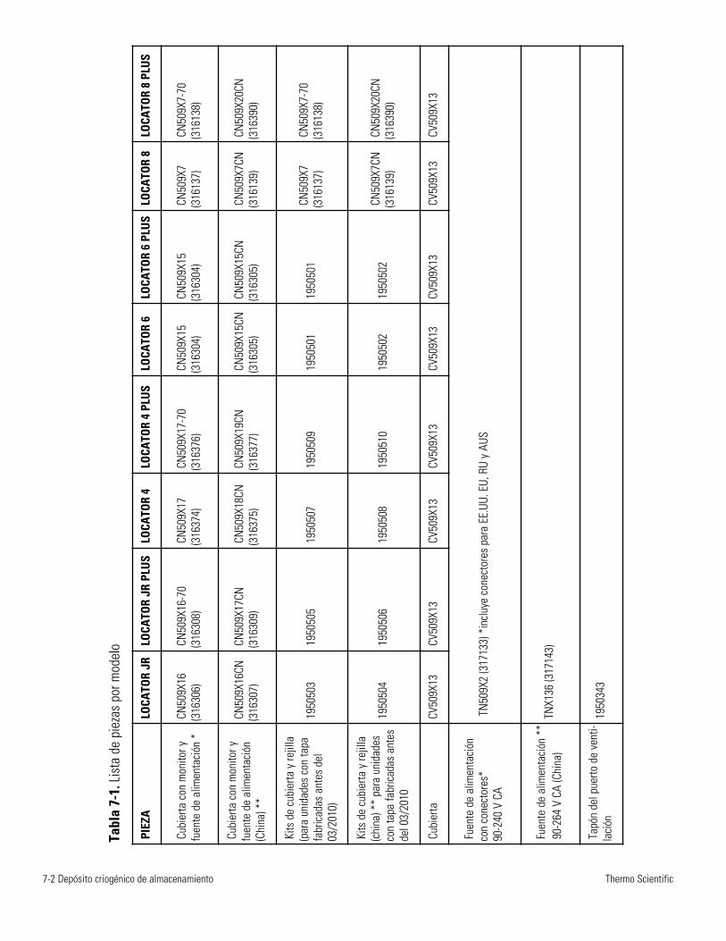
7-2 Depósito criogénico de almacenamiento Thermo Scientific
PIEZ
A
LOCA
TOR
JRLO
CATO
R JR
PLU
SLO
CATO
R 4
LOCA
TOR
4 PL
US
LOCA
TOR
6LO
CATO
R 6
PLU
SLO
CATO
R 8
LOCA
TOR
8 PL
US
Cubi
erta
con
mon
itor y
fuen
te d
e al
imen
taci
ón *
CN50
9X16
(316
306)
CN50
9X16
-70
(316
308)
CN50
9X17
(316
374)
CN50
9X17
-70
(316
376)
CN50
9X15
(316
304)
CN50
9X15
(316
304)
CN50
9X7
(316
137)
CN50
9X7-
70(3
1613
8)
Cubi
erta
con
mon
itor y
fuen
te d
e al
imen
taci
ón(C
hina
) **
CN50
9X16
CN(3
1630
7)
CN50
9X17
CN(3
1630
9)CN
509X
18CN
(316
375)
CN50
9X19
CN(3
1637
7)CN
509X
15CN
(316
305)
CN50
9X15
CN(3
1630
5)CN
509X
7CN
(316
139)
CN50
9X20
CN(3
1639
0)
Kits
de
cubi
erta
y re
jilla
(par
a un
idad
es c
on ta
pafa
bric
adas
ant
es d
el03
/201
0)
1950
503
1950
505
1950
507
1950
509
1950
501
1950
501
CN50
9X7
(316
137)
CN50
9X7-
70(3
1613
8)
Kits
de
cubi
erta
y re
jilla
(chi
na) *
* pa
ra u
nida
des
con
tapa
fabr
icad
as a
ntes
del 0
3/20
10
1950
504
1950
506
1950
508
1950
510
1950
502
1950
502
CN50
9X7C
N(3
1613
9)CN
509X
20CN
(316
390)
Cubi
erta
CV
509X
13CV
509X
13CV
509X
13
CV50
9X13
CV
509X
13
CV50
9X13
CV
509X
13
CV50
9X13
Fuen
te d
e al
imen
taci
ónco
n co
nect
ores
* 90
-240
V C
ATN
509X
2 (3
1713
3) *
incl
uye
cone
ctor
es p
ara
EE.U
U. E
U, R
U y
AUS
Fuen
te d
e al
imen
taci
ón *
* 90
-264
V C
A (C
hina
)TN
X136
(317
143)
Tapó
n de
l pue
rto d
e ve
nti-
laci
ón19
5034
3
Tabl
a 7-
1. L
ista
de
piez
as p
or m
odel
o
Locator ja Locator Plus Kryosäiliö
Ultrasonic-tasovalvojalla ja ilman Käyttöohje j a varaosaluettelo
LT509X9 (7018141) Rev.4
© 2010 T hermo Fisher Scientific All rights reserved Printed in U.S.A.
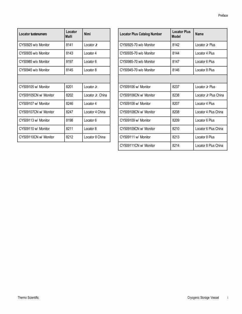
Preface
Thermo Scientific Cryogenic Storage Vessel i
Locator Plus Catalog Number Locator Plus Model Name
CY50925-70 w/o Monitor 8142 Locator Jr Plus
CY50935-70 w/o Monitor 8144 Locator 4 Plus
CY50985-70 w/o Monitor 8147 Locator 6 Plus
CY50945-70 w/o Monitor 8146 Locator 8 Plus
CY509106 w/ Monitor 8237 Locator Jr Plus
CY509106CN w/ Monitor 8238 Locator Jr Plus China
CY509108 w/ Monitor 8207 Locator 4 Plus
CY509108CN w/ Monitor 8208 Locator 4 Plus China
CY509109 w/ Monitor 8209 Locator 6 Plus
CY509109CN w/ Monitor 8210 Locator 6 Plus China
CY509111 w/ Monitor 8213 Locator 8 Plus
CY509111CN w/ Monitor 8214 Locator 8 Plus China
Locator tuotenumero Locator Malli Nimi
CY50925 w/o Monitor 8141 Locator Jr
CY50935 w/o Monitor 8143 Locator 4
CY50985 w/o Monitor 8197 Locator 6
CY50945 w/o Monitor 8145 Locator 8
CY509105 w/ Monitor 8201 Locator Jr.
CY509105CN w/ Monitor 8202 Locator Jr. China
CY509107 w/ Monitor 8246 Locator 4
CY509107CN w/ Monitor 8247 Locator 4 China
CY509113 w/ Monitor 8198 Locator 6
CY509110 w/ Monitor 8211 Locator 8
CY509110CN w/ Monitor 8212 Locator 8 China
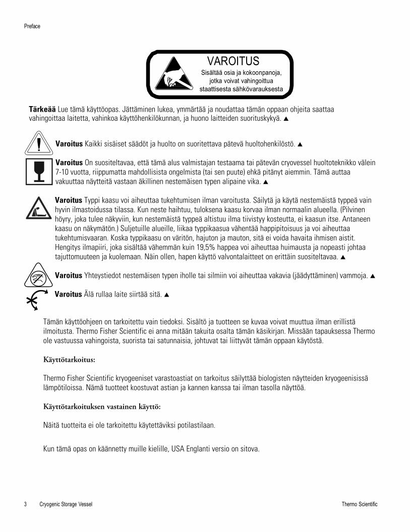
Preface
3 Cryogenic Storage Vessel Thermo Scientific
VAROITUS Sisältää osia ja kokoonpanoja,
jotka voivat vahingoittua staattisesta sähkövarauksesta
Tärkeää Lue tämä käyttöopas. Jättäminen lukea, ymmärtää ja noudattaa tämän oppaan ohjeita saattaa vahingoittaa laitetta, vahinkoa käyttöhenkilökunnan, ja huono laitteiden suorituskykyä. s
Varoitus Kaikki sisäiset säädöt ja huolto on suoritettava pätevä huoltohenkilöstö. s
Varoitus On suositeltavaa, että tämä alus valmistajan testaama tai pätevän cryovessel huoltoteknikko välein7-10 vuotta, riippumatta mahdollisista ongelmista (tai sen puute) ehkä pitänyt aiemmin. Tämä auttaavakuuttaa näytteitä vastaan äkillinen nestemäisen typen alipaine vika. s
Varoitus Typpi kaasu voi aiheuttaa tukehtumisen ilman varoitusta. Säilytä ja käytä nestemäistä typpeä vainhyvin ilmastoidussa tilassa. Kun neste haihtuu, tuloksena kaasu korvaa ilman normaalin alueella. (Pilvinenhöyry, joka tulee näkyviin, kun nestemäistä typpeä altistuu ilma tiivistyy kosteutta, ei kaasun itse. Antaneenkaasu on näkymätön.) Suljetuille alueille, liikaa typpikaasua vähentää happipitoisuus ja voi aiheuttaatukehtumisvaaran. Koska typpikaasu on väritön, hajuton ja mauton, sitä ei voida havaita ihmisen aistit.Hengitys ilmapiiri, joka sisältää vähemmän kuin 19,5% happea voi aiheuttaa huimausta ja nopeasti johtaatajuttomuuteen ja kuolemaan. Näin ollen, hapen käyttö valvontalaitteet on erittäin suositeltavaa. s
Varoitus Yhteystiedot nestemäisen typen iholle tai silmiin voi aiheuttaa vakavia (jäädyttäminen) vammoja. s
Varoitus Älä rullaa laite siirtää sitä. s
Tämän käyttöohjeen on tarkoitettu vain tiedoksi. Sisältö ja tuotteen se kuvaa voivat muuttua ilman erillistäilmoitusta. Thermo Fisher Scientific ei anna mitään takuita osalta tämän käsikirjan. Missään tapauksessa Thermoole vastuussa vahingoista, suorista tai satunnaisia, johtuvat tai liittyvät tämän oppaan käytöstä.
Käyttötarkoitus:
Thermo Fisher Scientific kryogeeniset varastoastiat on tarkoitus säilyttää biologisten näytteiden kryogeenisissälämpötiloissa. Nämä tuotteet koostuvat astian ja kannen kanssa tai ilman tasolla näyttöä.
Käyttötarkoituksen vastainen käyttö:
Näitä tuotteita ei ole tarkoitettu käytettäviksi potilastilaan.
Kun tämä opas on käännetty muille kielille, USA Englanti versio on sitova.
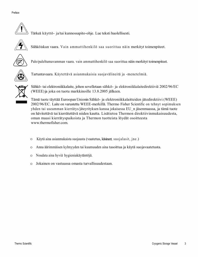
Preface
Thermo Scientific Cryogenic Storage Vessel 3
Tärkeä käyttö- ja/tai kunnossapito-ohje. Lue teksti huolellisesti.
Sähköiskun vaara. Va in a mmat t i henki lö saa suor i t taa nä in merkityt toimenpiteet.
Palo/paleltumavamman vaara. vain ammattihenkilö saa suorittaa näin merkityt toimenpiteet.
Tartuntavaara. Käytettävä asianmukaisia suojavälineitä ja -menetelmiä.
Sähkö- tai elektroniikkalaite, johon sovelletaan sähkö- ja elektroniikkalaitedirektiiviä 2002/96/EC (WEEE) ja joka on tuotu markkinoille 13.8.2005 jälkeen.
Tämä tuote täyttää Euroopan Unionin Sähkö- ja elektroniikkalaitteiden jätedirektiivi (WEEE) 2002/96/EC. Laite on varustettu WEEE-merkillä. Thermo Fisher Scientific on tehnyt sopimuksen yhden tai useamman kierrätys/jäteyrityksen kanssa jokaisessa EU_n jäsenmaassa, ja tämä tuote on hävitettävä tai kierrätettävä niiden kautta. Lisätietoa Thermon direktiivinmukaisuudesta, oman maasi kierrätyspaikoista ja Thermon tuotteista löydät osoitteesta www.thermofisher.com.
o Käytä aina asianmukaista suojausta (vaatetus, käsineet, suoj alas i t , j ne.)
o Anna äärimmäisen kylmyyden tai kuumuuden aina tasoittua ja käytä suojavaatetusta.
o Noudata aina hyviä hygieniakäytäntöjä.
o Jokainen on vastuussa omasta turvallisuudestaan.
Preface
4 Cryogenic Storage Vessel Thermo Scientific
Tarvitsetko tietoa tai apua Thermo Scientific -tuotteista?
If you do, please contact us 8:00 a.m. to 6:00 p.m. (Eastern Time) at:
1-740-373-4763 Direct 1-800-438-4851 Toll Free, U.S. and Canada 1-877-213-8051 FAX http://www.thermoscientific.com Internet Worldwide Web Home Page [email protected] Tech Support Email Address www.unitylabservices.com Certified S ervice Web Page
Our Sales Support staff can provide information on pricing and give you quotations. We can take your order and provide delivery information on major equipment items or make arrangements to have your local sales representative contact you. Our products are listed on the Internet and we can be contacted through our Internet home page.
Our Service Support staff can supply technical information about proper setup, operation or troubleshooting of your equipment. We can fill your needs for spare or replacement parts or provide you with on-site service. We can also provide you with a quotation on our Extended Warranty for your Thermo Scientific products.
Whatever Thermo Scientific products you need or use, we will be happy to discuss your applications. If you are experiencing technical problems, working together, we will help you locate the problem and, chances are, correct it yourself...over the telephone without a service call.
When more extensive service is necessary, we will assist you with direct factory trained technicians or a qualified service organization for on-the-spot repair. If your service need is covered by the warranty, we will arrange for the unit to be repaired at our expense and to your satisfaction.
Regardless of your needs, our professional telephone technicians are available to assist you Monday through Friday from 8:00 a.m. to 6:00 p.m. Eastern Time. Please contact us by telephone or fax. If you wish to write, our mailing address is:
Thermo Fisher Scientific (Asheville) LLC 401 Millcreek Road, Box 649 Marietta, OH 45750
International customers, please contact your local Thermo Scientific distributor.
Thermo Scientific Cryogenic Storage Vessel 5
Sisällys
Luku 1
Luku 2
Luku 3
Luku 4
Luku 5
Luku 6
Luku 7
Turvallisuusohjeet . . . . . . . . . . . . . . . . . . . . . . . . . . . . . . . . . . . . . . . . . . . .1-1 Lue tämä! . . . . . . . . . . . . . . . . . . . . . . . . . . . . . . . . . . . . . .1-11 Yleisohjeet . . . . . . . . . .. . . . . . . . . . . . . . . . . . . . . . . . . . .1- Vaarat . . . . . . . . . . . . . . . . . . . . . . . . . . . . . . . . . . . . . . . .1-2 Varoitukset . . . . . . . . . .. . . . . . . . . . . . . . . . . . . . . . . . . . .1-2
Tekniset tiedot …………… . . . . . . . . . . . . . . . . . . . . . . . . . . . . . . . . . . . . . . .2-1 Ympäristöolosuhteet …….. . . . . . . . . . . . . . . . . . . . . . . . .2-1
Pakkauksen purkaminen . . . . . . . . . . . . . . . . . . . . . . . . . . . . . . . . . . . . . . . . . .3-1
Käyttöohje . . . . . . . . . . . . . . . . . . . . . . ……. . . . . . . . . . . . . . . . . . . . . . . . . . . . . .4-1 Nestetypen määrän mittaaminen . . . . . . . . . . . . . . . . . . . . . . . .4-1 Yleispuhdistusohjeet . . . . . . . …. . . . . . . . . . . . . . . . . . . . . . .4-2 Näytteiden säilyttäminen kaasutilassa . . ... . . . . . . . . . . . . . . . .4-2 Varoitukset . . . . . . . . . . . . . . . . . . . . . . . . . . . . . . . . . . . . . . . . . . .4-2
Varaosat … … … … . . . . . . . . . . . . . . . . . . . . . . . . . . . . . . . .. . . . ... . . . . . . . .5-1
Nestetypen tasovalvojan toiminta . . . . . . . . . . . . . . . . . . . . . . . . . . . . . . . . .6-1 Asennus . . . . . . . . . . . . . . . . . . . . . . . . . . . . . . . . . . . . . . . .6-1 Etähälytys . . . . . . . . . . . . . . ... . . . . . . . . . . . . . . . . . . . . . . .6-1 Hälytyskontaktien tekniset tiedot . . . . . . . . . . . . . . . . . . . . . . .6-2 Mikroprosessorin toiminnot . . . . . . .. . . . . . . . . . . . . . . . . . . .6-4 Toimintaperiaate . . . . . . . . . . . . . . . . . . . . . . . . . . . . . . . . . .6-4 Tasomittarin toiminta . . . . . . . . . . . . . . . . . . . . . . . . . . . . . . .6-5 Turvaominaisuus . . . . . . . . . . . . . . . . . .. . . . . . . . . . . . . . . . . .6-5 Audio-visuaaliset hälytykset . . . . . . . . . . . . . . . . . . . . . . . . . .6-5
LN2-tasovalvojan vianmääritys ja varaosaluettelo .. . . . . . . . . . . . . . . . . .7-1 Tilauskäytäntö. . . . . . . . . . . . . . . . . . . . . . . . . . . . . . . . . . . .7-2
Thermo Scientific Cryogenic Storage Vessel 1-1
Luku 1 Turvallisuusohjeet Tämä käyttöohje sisältää tärkeitä käyttö- ja turvallisuusohjeita. Käyttäjän on luettava huolellisesti ja ymmärrettävä tämän ohjeen sisältö ennen laitteen käyttöä.
Thermo Scientific kryosäiliön suunnittelussa on huomioitu toimivuus, luotettavuus ja turvallisuus. Käyttäjän vastuulla on asentaa se paikallisten sähköturvallisuusmääräysten mukaisesti. Jotta käyttö olisi turvallista, käyttöohjeen sisältämiin vaara- ja varoitusmerkintöihin on kiinnitettävä huomiota.
Lue tämä!
Yleisohje
Kaikissa kryosäiliöissä valmistajasta riippumatta käytetään erittäin tehokkaasti eristävää vakuumia typen pitämiseksi nestemuodossa. Ne ovat keskenään hyvin samanlaisia, ja olet itse asiassa saattanut säilyttää Thermon® valmistamassa termospullossa kahvia, keittoa tai maitoa.
Muistathan, kuinka helposti särkyviä ne ovat? Koska vakuumi ei ole täydellinen eikä säily loputtomiin, suosittelemme, että seuraat nestetypen kulutusta säännöllisesti, 1-2 päivän välein. Näin pystyt ennakoimaan pienet muutokset kulutuksessa ja reagoimaan mahdollisiin ongelmiin jo ennen niiden ilmenemistä. Tähän tarkoitukseen voi käyttää ltasovalvojaa (katso sivu 6-1).
Mikäli näytteet ovat erityisen arvokkaita, ainutkertaisia tai korvaamattomia, harkitse niiden jakamista kahteen erilliseen säiliöön. Muista vanha varoitus kaikkien munien laittamisesta samaan koriin.
Lopuksi, koska mikään vakuumi ei kestä ikuisesti, tarkistuta säiliöt valmistajalla tai kryosäiliöiden huoltoammattilaisella 7-10 vuoden välein riippumatta siitä, onko ongelmia ilmennyt menneisyydessä vai ei. Tämä auttaa varmistamaan, etteivät näytteet jää yllättäen ilman typpeä vakuumin pettämisen vuoksi.
Älä käytä tätä tuotetta mihinkään muuhun kuin alkuperäiseen käyttötarkoitukseen.
Laitteen käyttö muutoin kuin valmistajan ohjeistamalla tavalla voi vioittaa laitteen suojauksia.
1-2 Cryogenic Storage Vessel Thermo Scientific
Luka 1Turvallisuusohjeet
Vaarat • Tämä laite on tarkoitettu vain ammattikäyttöön hyvinilmastoiduissa tiloissa.
• Nestetyppi on äärimmäisen kylmää; se kiehuu -196°C:ssa.
• Noudata kylmätekniikka-alueella kaikkia tarpeelllisia varotoimia javaroituksia, jotka liittyvät paleltumien, ckosketusvammojen ,tukehtumiskuoleman ym. ehkäisyyn.
• Noudata paleltumisvammojen ja putkien särkymisen ehkäisemiseksiäärimmäistä varovaisuutta nestetypen käsittelyssä, varastoinnissa jasiirrossa sekä kaikkien nestetypen kanssa kosketuksiin joutuneidenesineiden käsittelyssä.
• Älä jätä mitään ihoalueita alttiiksi nestetypelle.
• Käytä asianmukaisia henkilökohtaisia suojaimia aina tarvittaessa;kasvosuojainta, kylmäkäsineitä, kylmäsuojausesiliinaa.
• Älä sulje nestetyppiastioita tiiviisti äläkä estä typpikaasua haihtumasta.
• Käsittele ampulleja aina pihtien avulla. Ampullit voivat räjähtää, kunne nostetaan pois säiliöstä.
• Noudata äärimmäistä varovaisuutta, ettei nestetyppi roisku tailäiky, kun sitä siirretään tai poistetaan varastoastioista.
• Riisu välittömästi suojavaate tai muu, jos sille on roiskunut taikaatunut nestetyppeä.
• Hakeudu välittömästi lääkärin hoitoon, jos saat nestetypestäpaleltumavammoja.
Thermo Scientific Cryogenic Storage Vessel 1-3
Varoitukset • Käytä vain laitteen mukana toimitettua
virtalähdettä.
Luku 1 Turvallisuusohjeet
• Älä koskaan täytä nestetyppisäiliötä liian täyteen. Nestetypen taso ei saakoskaan ylittää säiliön sisällä olevien telineiden yläpintaa.Ylimääräinen paino voi rikkoa kaulan ja johtaa vakuumin pettämiseen.
• Varo telineitä lisätessäsi ja poistaessasi, ettet kosketa säiliönkaulaosaa. Poista ja lisää telineitä vain pystyasennossa. Kaulan alueellesyntyneet naarmut voivat johtaa vakuumin ennenaikaiseen pettämiseen.
• Älä kajoa vakuumiporttiin tai irrota sitä (säiliön puolella mustanmuovitulpan peitossa); muuten takuu raukeaa.
• Älä läikytä nestetyppeä vakuumiportin päälle - se voi johtaavakuumin pettämiseen.
• Pidä nestetyppisäiliö aina pystyasennossa.
• Älä käytä Locator-säiliötä siirtotarkoitukseen.
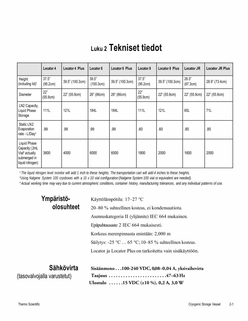
Luku 2 Tekniset tiedot
Thermo Scientific Cryogenic Storage Vessel 2-1
Locator 4 Locator 4 Plus Locator 6 Locator 6 Plus Locator 8 Locator 8 Plus Locator JR Locator JR Plus
Height (including lid)1
37.5” (95.2cm) 39.5” (100.3cm)
39.5” (100.3cm) 39.5” (100.3cm)
37.5” (95.2cm) 39.5” (100.3cm)
26.5” (67.3cm) 28.9” (73.4cm)
Diameter 22” (55.9cm) 22” (55.9cm) 26” (66cm) 26” (66cm) 22”
(55.9cm) 22” (55.9cm) 22” (55.9cm) 22” (55.9cm)
LN2 Capacity, Liquid Phase Storage
111L 121L 184L 184L 111L 121L 60L 71L
Static LN2 Evaporation rate - L/Day3
.99 .99 .99 .99 .60 .60 .85 .85
Liquid Phase Capacity ( 2mL Vial2 actually submerged in liquid nitrogen)
3600 4000 6000 6000 1800 2000 1600 2000
1 The liquid nitrogen level monitor will add 1 inch to these heights. The transportation cart will add 4 inches to these heights. 2 Using Nalgene System 100 cryoboxes with a 10 x 10 vial configuration (Nalgene System 100 vial or equivalent are needed). 3 Actual working time may vary due to current atmospheric conditions, container history, manufacturing tolerances, and any individual patterns of use.
Ympäristö- olosuhteet
Käyttölämpötila: 17–27 °C
20–80 % suhteellinen kosteus, ei kondensaatiota.
Asennuskategoria II (ylijännite) IEC 664 mukainen.
Epäpuhtausaste 2 IEC 664 mukaisesti.
Korkeus merenpinnasta enintään: 2,000 m
Säilytys: -25 °C … 65 °C; 10–85 % suhteellinen kosteus.
Locator ja Locator Plus on tarkoitettu vain sisäkäyttöön.
Sähkövirta Sisäänmeno . . .100-240 VDC, 0,08–0,04 A, yksivaihevirta
(tasovalvojalla varustetut) Taajuus . . . . . . . . . . . . . . . . . . . . . . . .47–63 Hz Ulostulo . . . . . .15 VDC (±10 %), 0,2 A, 3,0 W
Luku 3 Pakkauksen purkaminen
Thermo Scientific Cryogenic Storage Vessel 3-1
Ennen kuin käytät uutta Locator tai Locator Plus -säiliötä,tarkasta se huolellisesti. Etsi merkkejä vahingoittumisesta, joka on voinut tapahtua kuljetuksen aikana. On suositeltavaa täyttää (katso täyttöohje) kaikki uudet säiliöt nestetypellä ja seurata nestetypen hävikkivauhtia muutama päivä. Ongelmien ilmetessä ota mahdollisimman pian yhteys asiakaspalveluun.
Säiliön mukana tullut takuun rekisteröintikortti tulee täyttää ja palauttaa tehtaalle 30 päivän kuluessa, jotta takuu astuu voimaan. Tietoihin tulee sisältyä laitteen sarjanumero, joka löytyy laitekilvestä.
Huom. Yleisin syy nestetyppisäiliöiden pettämiseen on mekaaninen. Säiliön kaulaputki kantaa sisäosan koko painon ja kaiken sen sisältämän nestetypen. Sivulta säiliöön tuleva isku saa sisäosan heiluriliikkeeneen, joka vahingoittaa kaulapautkea. Säiliöt, joille on tapahtunut vahinko, jotka on pudotettu tai tai kallitettu kyljelleen, menettävät vakuuminsa nopeammin kuin vahingoittumattomat.
Varoitus Noudata varovaisuutta, kun siirrät Locator tai Locator Plus -säiliötä. Locator ja Locator Plus biologiset kryosäilytysjärjestelmät eivät ole siirtosäiliöitä. Siirtovaunut on tarkoitettu vain laboratorion sisällä tapahtuvaan siirtämiseen. Täysien säiliöiden siirtäminen pitkiä matkoja, lattiassa olevien rakojen, kynnysten tai kaltevien ramppien yli tai kuljettaminen hississä voi johtaa vakuumin ennenaikaiseen pettämiseen.
Huom. Jos näytteitä on siirrettävä kylmäolosuhteissa, käytä Arctic Express -tuotesarjan siirtosäiliöitä, joita on saatavana Thermo Scientificista.
Vältä liiallista voimaa, kun liikkuva alus; tämä voi aiheuttaa kaatumisen, aiheuttaen vahinkoa ja / tai valuu nestemäistä typpeä.
Luku 4 Käyttöohje
Thermo Scientific Cryogenic Storage Vessel 4-1
Täyttöohjeet
Caution Never overfill your Locator or Locator Plus vessel with liquid nitrogen. The liquid nitrogen level in your tank (with racks inserted) should never be above 20 inches (50cm) for Locator 4 and Locator 8, 10 inches (25cm) for Locator Jr., 22 inches (55.8cm) for Locator 4, 6, and 8 Plus and 12 inches for Locator Jr. Plus. Filling the tank up to or above the bottom of the necktube may cause immediate or premature vacuum failure to occur. s
Caution When inserting or removing racks, be careful not to come in contact with the necktube area of the vessel. Remove or insert racks slowly in a vertical manner. Scratches on the necktube area can cause premature vacuum failure. s
Caution Do not spill liquid nitrogen on vacuum port (covered by a black plastic cap on side of vessel). This can cause vacuum failure. s
To avoid damage to your Locator or Locator Plus cryogenic storage vessel which may result in premature vacuum loss, it is important that the following procedure be used when adding liquid nitrogen to a warm vessel.
1. Add only a small amount of liquid nitrogen (5-10 liters) to a new orwarm vessel.
2. Allow this small amount of liquid nitrogen to sit in the covered vesselfor a minimum of 2 hours. This will limit stress caused by the suddentemperature change associated with adding liquid nitrogen to a warmvessel.
3. Add an additional 15 liters of liquid nitrogen to the vessel.
4. Allow vessel to sit for 48 hours and monitor liquid nitrogenconsumption with a wooden yarsdstick, optional dip measurer (part#180143) or Level Monitor.
5. Fill Locator or Locator Plus as indicated (see Caution in this section).Allow for displacement of liquid nitrogen when racks and boxes areinserted.
6. Insert and remove racks slowly. Allow liquid nitrogen to run out ofboxes and off racks.
Section 4 Operation
5-2 Cryogenic Storage Vessel Thermo Scientific
Measuring Liquid Nitrogen Q uantity
Storing Samples in Vapor Phase
General Cleaning Instructions
1. Use a wooden yardstick or optional dip measurer (part #180143) tomeasure liquid nitrogen level. NEVER use a hollow tube or plasticdipstick to measure the liquid nitrogen level.
2. Level will be indicated by the frostline which develops when dipstick isremoved.
3. Level Monitor can be used for constant measurements. See Section 6.
1. Remove the 2 bottom-most cryoboxes from each rack.
2. Measure the height of 2 cryoboxes stacked on top of each other.
3. Fill vessel with liquid nitrogen to the height obtained from Step 2,using a yardstick to measure liquid level in vessel.
4. Place racks into vessel without the 2 bottom-most cryoboxes. Samplesare now above the liquid nitrogen and are stored in the vapor phase.
Important A level monitor should always be used when you store your samples in the vapor phase because of the already low levels of liquid nitrogen. Refer to Section 5 for correct level monitor for your system. s
Wipe exterior surfaces with lightly dampened cloth containing mild soap solution.
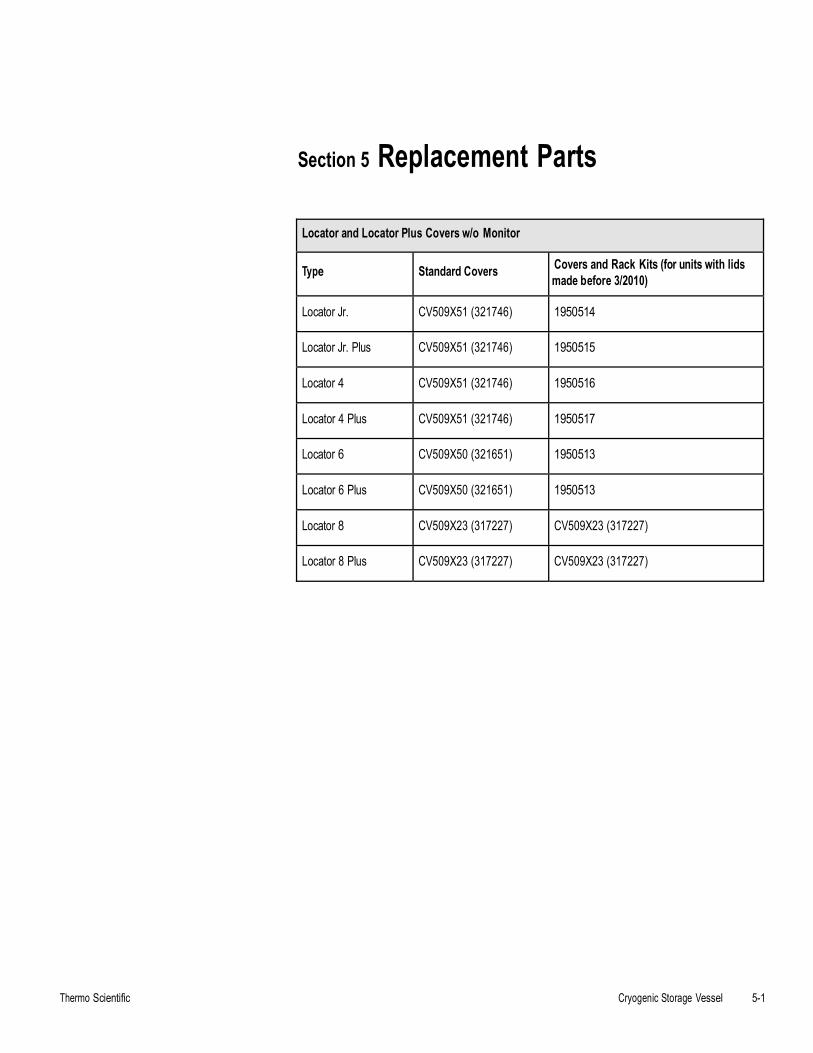
Section 5 Replacement Parts
Thermo Scientific Cryogenic Storage Vessel 5-1
Locator and Locator Plus Covers w/o Monitor
Type Standard Covers Covers and Rack Kits (for units with lids made before 3/2010)
Locator Jr. CV509X51 (321746) 1950514
Locator Jr. Plus CV509X51 (321746) 1950515
Locator 4 CV509X51 (321746) 1950516
Locator 4 Plus CV509X51 (321746) 1950517
Locator 6 CV509X50 (321651) 1950513
Locator 6 Plus CV509X50 (321651) 1950513
Locator 8 CV509X23 (317227) CV509X23 (317227)
Locator 8 Plus CV509X23 (317227) CV509X23 (317227)
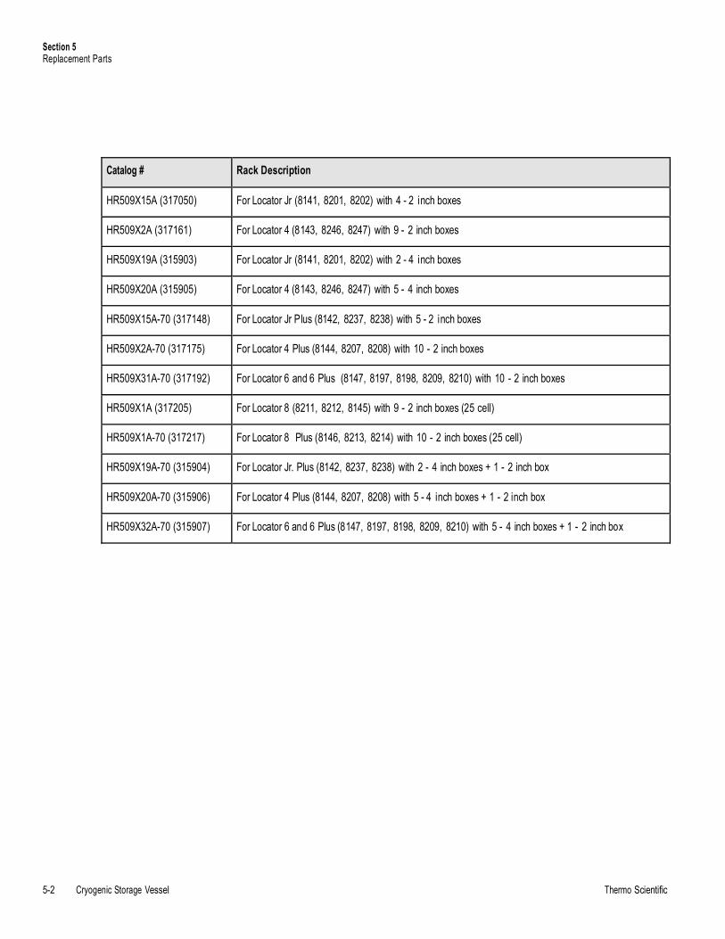
Section 5 Replacement Parts
5-2 Cryogenic Storage Vessel Thermo Scientific
Catalog # Rack Description
HR509X15A (317050) For Locator Jr (8141, 8201, 8202) with 4 - 2 inch boxes
HR509X2A (317161) For Locator 4 (8143, 8246, 8247) with 9 - 2 inch boxes
HR509X19A (315903) For Locator Jr (8141, 8201, 8202) with 2 - 4 inch boxes
HR509X20A (315905) For Locator 4 (8143, 8246, 8247) with 5 - 4 inch boxes
HR509X15A-70 (317148) For Locator Jr Plus (8142, 8237, 8238) with 5 - 2 inch boxes
HR509X2A-70 (317175) For Locator 4 Plus (8144, 8207, 8208) with 10 - 2 inch boxes
HR509X31A-70 (317192) For Locator 6 and 6 Plus (8147, 8197, 8198, 8209, 8210) with 10 - 2 inch boxes
HR509X1A (317205) For Locator 8 (8211, 8212, 8145) with 9 - 2 inch boxes (25 cell)
HR509X1A-70 (317217) For Locator 8 Plus (8146, 8213, 8214) with 10 - 2 inch boxes (25 cell)
HR509X19A-70 (315904) For Locator Jr. Plus (8142, 8237, 8238) with 2 - 4 inch boxes + 1 - 2 inch box
HR509X20A-70 (315906) For Locator 4 Plus (8144, 8207, 8208) with 5 - 4 inch boxes + 1 - 2 inch box
HR509X32A-70 (315907) For Locator 6 and 6 Plus (8147, 8197, 8198, 8209, 8210) with 5 - 4 inch boxes + 1 - 2 inch box
Section 6 Liquid Nitrogen Level
Thermo Scientific Cryogenic Storage Vessel 6-1
Monitor Operation
The liquid nitrogen (LN2) level monitor provides a constant indication of the LN2 level and notifies you to low level conditions through audible and visual alarms. It alerts you when your vessel needs filling. The level monitor is shipped mounted directly to the appropriate Locator or Locator Plus cover. It can be wired to a remote alarm system to alert you to problems when you are not in your laboratory. This equipment was intended to be operated with an external power supply provided by the manufacturer. It is designed for use with Thermo Scientific LN2 vessels only.
Caution Use this product for its intended usage only. s
Warning Potential electrical hazards. Only qualified persons should perform procedures associated with this symbol. s
Installation
Note If the level monitor was purchased as part of a Locator or LocatorPlus system, skip to Step 3. If it is a retrofit for an existing Locator or Locator Plus, begin with Step 1. s
1. Remove the level monitor and Locator or Locator Plus cover from box.
2. Remove present cover from your Locator or Locator Plus and replacewith your new level monitor and cover.
3. Check the electrical specifications on the power supply for electricaldata and plug in to appropriately grounded receptacle.
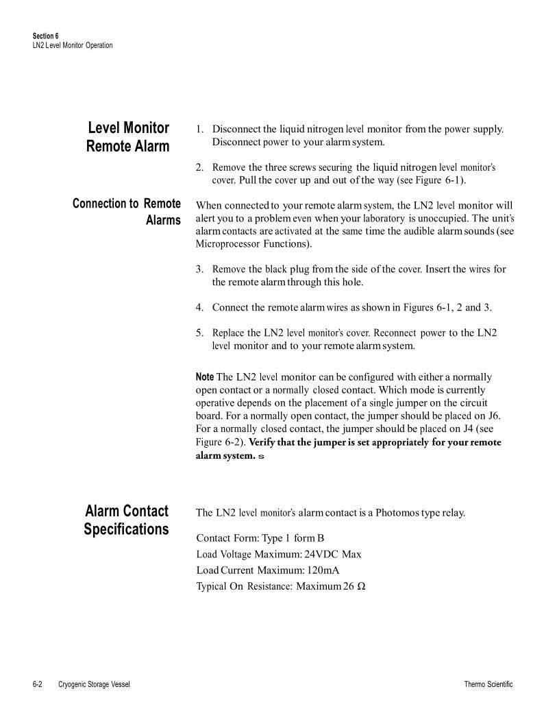
Section 6 LN2 Level Monitor Operation
6-2 Cryogenic Storage Vessel Thermo Scientific
Level Monitor Remote Alarm
Connection to Remote Alarms
Alarm Contact Specifications
1. Disconnect the liquid nitrogen level monitor from the power supply.Disconnect power to your alarm system.
2. Remove the three screws securing the liquid nitrogen level monitor’scover. Pull the cover up and out of the way (see Figure 6-1).
When connected to your remote alarm system, the LN2 level monitor will alert you to a problem even when your laboratory is unoccupied. The unit’s alarm contacts are activated at the same time the audible alarm sounds (see Microprocessor Functions).
3. Remove the black plug from the side of the cover. Insert the wires forthe remote alarm through this hole.
4. Connect the remote alarm wires as shown in Figures 6-1, 2 and 3.
5. Replace the LN2 level monitor’s cover. Reconnect power to the LN2level monitor and to your remote alarm system.
Note The LN2 level monitor can be configured with either a normally open contact or a normally closed contact. Which mode is currently operative depends on the placement of a single jumper on the circuit board. For a normally open contact, the jumper should be placed on J6. For a normally closed contact, the jumper should be placed on J4 (see Figure 6-2). Verify that the jumper is set appropriately for your remote alarm system. s
The LN2 level monitor’s alarm contact is a Photomos type relay.
Contact Form: Type 1 form B
Load Voltage Maximum: 24VDC Max
Load Current Maximum: 120mA
Typical On Resistance: Maximum 26 Ω
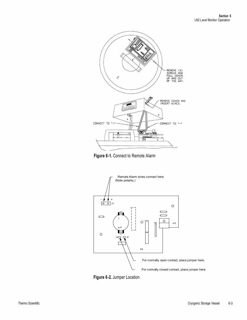
Section 6 LN2 Level Monitor Operation
Thermo Scientific Cryogenic Storage Vessel 6-3
Figure 6-1. Connect to Remote Alarm
Remote Alarm wires connect here (Note polarity.)
- + J3
1
1 1
J4 J6
For normally open contact, place jumper here.
For normally closed contact, place jumper here.
Figure 6-2. Jumper Location
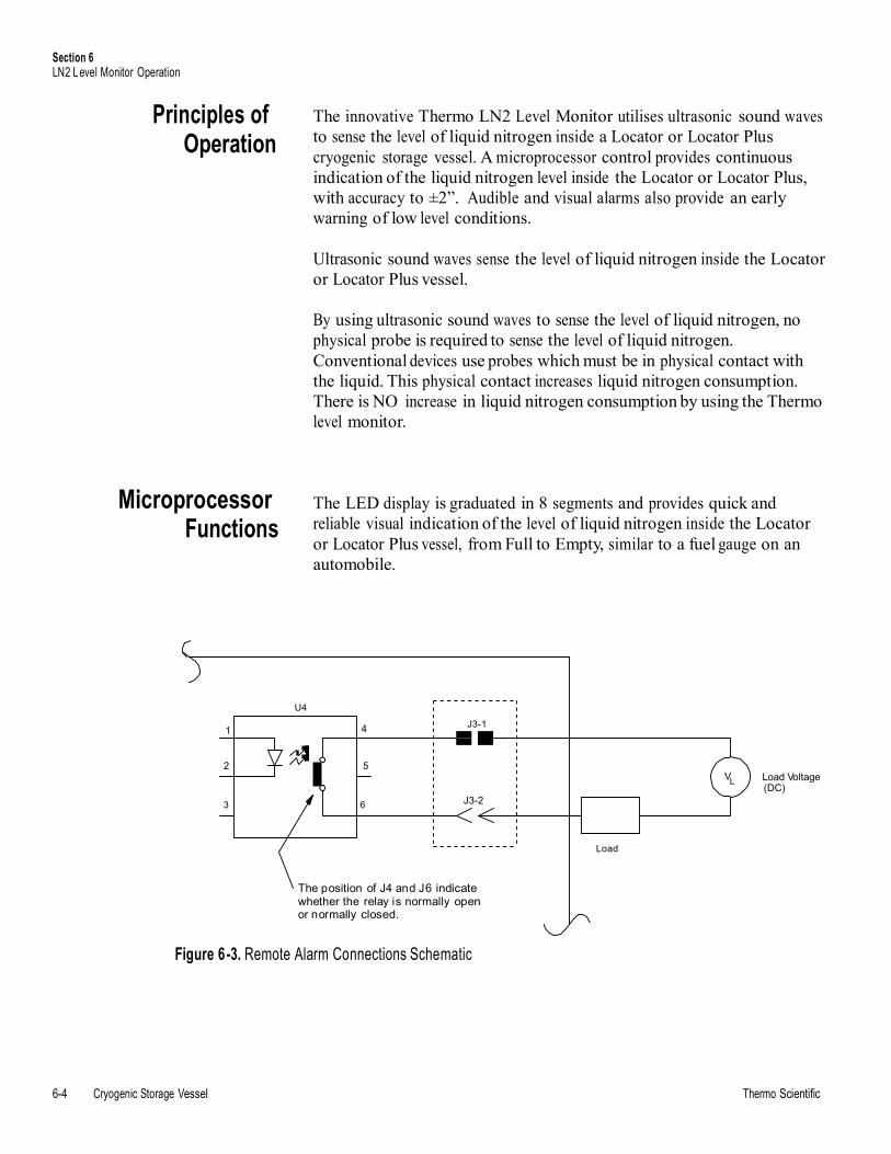
Section 6 LN2 Level Monitor Operation
6-4 Cryogenic Storage Vessel Thermo Scientific
L
4
Principles of Operation
Microprocessor Functions
The innovative Thermo LN2 Level Monitor utilises ultrasonic sound waves to sense the level of liquid nitrogen inside a Locator or Locator Plus cryogenic storage vessel. A microprocessor control provides continuous indication of the liquid nitrogen level inside the Locator or Locator Plus, with accuracy to ±2”. Audible and visual alarms also provide an early warning of low level conditions.
Ultrasonic sound waves sense the level of liquid nitrogen inside the Locator or Locator Plus vessel.
By using ultrasonic sound waves to sense the level of liquid nitrogen, no physical probe is required to sense the level of liquid nitrogen. Conventional devices use probes which must be in physical contact with the liquid. This physical contact increases liquid nitrogen consumption. There is NO increase in liquid nitrogen consumption by using the Thermo level monitor.
The LED display is graduated in 8 segments and provides quick and reliable visual indication of the level of liquid nitrogen inside the Locator or Locator Plus vessel, from Full to Empty, similar to a fuel gauge on an automobile.
U4
J3-1 1
2 5 V Load Voltage
3 6 J3-2 (DC)
Load
The position of J4 and J6 indicate whether the relay is normally open or normally closed.
Figure 6-3. Remote Alarm Connections Schematic
Section 6 LN2 Level Monitor Operation
Thermo Scientific Cryogenic Storage Vessel 6-5
Audible and Visual Alarms
Safety Feature
Level Monitor Operation
1. “LOW LEVEL” indicator light illuminates continuously when liquidnitrogen level is below the approximate 2" level. In this situation, thelevel of liquid nitrogen is low, and you are alerted to refill the vessel assoon as possible.
2. An AUDIBLE and remote alarm activates continuously when liquidnitrogen is below the approximate 1” level inside the Locator orLocator Plus vessel, additionally, “LOW LEVEL” light will continue toflash. In this situation, the liquid nitrogen is dangerously low, and youare alerted to refill the vessel immediately.
3. The AUDIBLE and remote alarms activate continuously, the 8-segment LED display and “Low LEVEL” lights flash, to indicate anemergency event. This alarm event occurs when the Locator or LocatorPlus vessel is empty of liquid nitrogen, or the monitor has an error andis incapable of detecting LN2 levels.
The microprocessor must be reset each time the cover is removed from the Locator or Locator Plus. Before removing the cover, the RESET button must be pressed, illuminating the RESET light. While in this Reset/Hold mode, the monitor is not sensing. After five minutes in the Reset/Hold mode, an audible and remote alarm will activate, alerting you to deactivate the Reset/Hold mode when the cover is replaced on the vessel.
Once the cover with the monitor has been placed on the vessel and plugged in, wait about 15 minutes for the system to equilibrate before pressing the Reset button for an accurate measurement of the liquid nitrogen to be indicated. This equilibration process will occur each time the cover is removed. Each time a vessel is opened or moved, the stabilized chamber temperature and/or liquid level is disrupted. The system requires a stable temperature and liquid level to determine an accurate liquid nitrogen level.
If you have just purchased a new Locator or Locator Plus along with your monitor, allow at least 1 day for the liquid nitrogen to equilibrate the vessel before plugging in the unit. This will avoid false alarms.
Note The Level Monitor may take up to 10 minutes to establish a reading after the unit is placed on the cryovessel, or the cryovessel is moved. Remember to press “Reset” after placing unit on the vessel. The green LED on the switch should be “OFF.” s
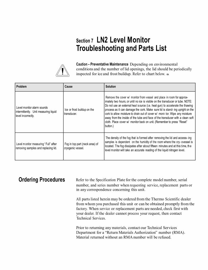
Section 7 LN2 Level Monitor Troubleshooting and Parts List
Caution - Preventative Maintenance Depending on environmental conditions and the number of lid openings, the lid should be periodically inspected for ice and frost buildup. Refer to chart below. s
Problem Cause Solution
Level monitor alarm sounds intermittently. Unit measuring liquid level incorrectly.
Ice or frost buildup on the transducer.
Remove the cover w/ monitor from vessel and place in room for approx- imately two hours, or until no ice is visible on the transducer or tube. NOTE: Do not use an external hea t source (i.e. heat gun) to accelerate the thawing process as it can damage the cork. Make sure lid is stand- ing upright on the cork to allow moisture to drain out of cover w/ moni- tor. Wipe any moisture away from the inside of the tube and face of the transducer with a clean soft cloth. Place cover w/ monitor back on unit. (Remember to press “Reset” button.)
Level m onitor measuring “ Full” after removing samples and replacing lid.
Fog in top part (neck area) of cryogenic vessel.
The density of the fog that is formed after removing the l id and access- ing samples is dependent on the humidity of the room where the cry- ovessel is located. The fog dissipates after about fifteen minutes and at this t ime, the level monitor will t ake an accurate reading of the l iquid nitrogen level.
Ordering Procedures Refer to the Specification Plate for the complete model number, serial number, and series number when requesting service, replacement parts or in any correspondence concerning this unit.
All parts listed herein may be ordered from the Thermo Scientific dealer from whom you purchased this unit or can be obtained promptly from the factory. When service or replacement parts are needed, check first with your dealer. If the dealer cannot process your request, then contact Technical Services.
Prior to returning any materials, contact our Technical Services Department for a “Return Materials Authorization” number (RMA). Material returned without an RMA number will be refused.
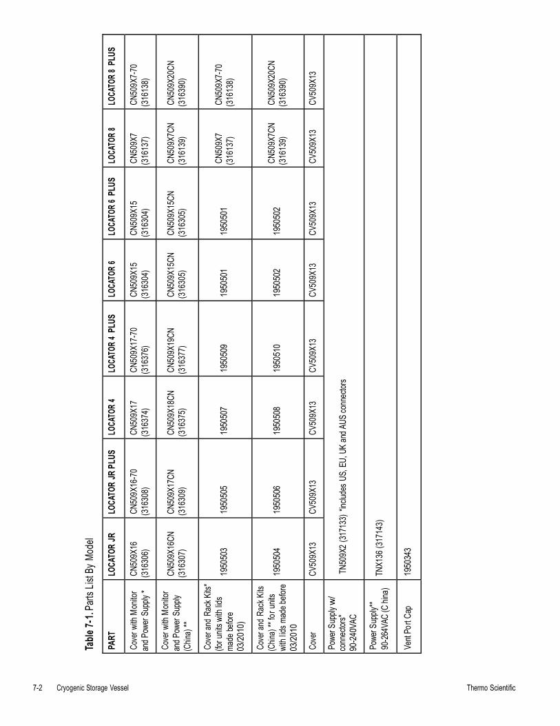
7-2 Cryogenic Storage Vessel Thermo Scientific
Table
7-1.
Parts
List
By M
odel
PART
LO
CATO
R JR
LO
CATO
R JR
PLU
S LO
CATO
R 4
LOCA
TOR
4 PL
US
LOCA
TOR
6 LO
CATO
R 6 PL
US
LOCA
TOR 8
LO
CATO
R 8 PL
US
Cove
r with
Mon
itor
and P
ower
Supp
ly *
CN50
9X16
(3
1630
6) CN
509X
16-7
0 (3
1630
8) CN
509X
17
(316
374)
CN50
9X17
-70
(316
376)
CN50
9X15
(3
1630
4) CN
509X
15
(316
304)
CN50
9X7
(316
137)
CN50
9X7-
70
(316
138)
Cove
r with
Mon
itor
and P
ower
Supp
ly (C
hina)
**
CN50
9X16
CN
(316
307)
CN50
9X17
CN
(316
309)
CN50
9X18
CN
(316
375)
CN50
9X19
CN
(316
377)
CN50
9X15
CN
(316
305)
CN50
9X15
CN
(316
305)
CN50
9X7C
N (3
1613
9) CN
509X
20CN
(3
1639
0)
Cove
r and
Rac
k Kits
* (fo
r unit
s with
lids
made
befor
e 03
/201
0)
1950
503
1950
505
1950
507
1950
509
1950
501
1950
501
CN50
9X7
(316
137)
CN50
9X7-
70
(316
138)
Cove
r and
Rac
k Kits
(C
hina)
** fo
r unit
s wi
th lid
s mad
e befo
re
03/2
010
1950
504
1950
506
1950
508
1950
510
1950
502
1950
502
CN50
9X7C
N (3
1613
9) CN
509X
20CN
(3
1639
0)
Cove
r CV
509X
13
CV50
9X13
CV
509X
13
CV50
9X13
CV
509X
13
CV50
9X13
CV
509X
13
CV50
9X13
Powe
r Sup
ply w
/ co
nnec
tors*
90-2
40VA
C TN
509X
2 (31
7133
) *inc
ludes
US,
EU,
UK
and A
US co
nnec
tors
Powe
r Sup
ply**
90-2
64VA
C (C
hina)
TN
X136
(317
143)
Vent
Port
Cap
1950
343
Locator and Locator PlusKryogénne skladovacie nádrže s alebo bez ultrazvukové sledovanie úrovne Návod na obsluhu a Zoznam dielov
LT509X9 (7018141) Rev. 4
© 2010 Thermo Fisher Scientific Všetky práva vyhradené Vytla.ené v U.S.A.
User M
anual
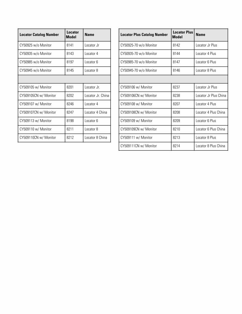
Locator Catalog Number LocatorModel Name
CY50925 w/o Monitor 8141 Locator Jr
CY50935 w/o Monitor 8143 Locator 4
CY50985 w/o Monitor 8197 Locator 6
CY50945 w/o Monitor 8145 Locator 8
CY509105 w/ Monitor 8201 Locator Jr.
CY509105CN w/ Monitor 8202 Locator Jr. China
CY509107 w/ Monitor 8246 Locator 4
CY509107CN w/ Monitor 8247 Locator 4 China
CY509113 w/ Monitor 8198 Locator 6
CY509110 w/ Monitor 8211 Locator 8
CY509110CN w/ Monitor 8212 Locator 8 China
Locator Plus Catalog Number Locator PlusModel Name
CY50925-70 w/o Monitor 8142 Locator Jr Plus
CY50935-70 w/o Monitor 8144 Locator 4 Plus
CY50985-70 w/o Monitor 8147 Locator 6 Plus
CY50945-70 w/o Monitor 8146 Locator 8 Plus
CY509106 w/ Monitor 8237 Locator Jr Plus
CY509106CN w/ Monitor 8238 Locator Jr Plus China
CY509108 w/ Monitor 8207 Locator 4 Plus
CY509108CN w/ Monitor 8208 Locator 4 Plus China
CY509109 w/ Monitor 8209 Locator 6 Plus
CY509109CN w/ Monitor 8210 Locator 6 Plus China
CY509111 w/ Monitor 8213 Locator 8 Plus
CY509111CN w/ Monitor 8214 Locator 8 Plus China
20
Dôležité Prečítajte si tento návod na použitie. Zlyhanie čítať, porozumieť a postupujte podľa pokynov v tejto príručke, môžu mať za následok aj poškodenie prístroja, zranenia obsluhujúceho personálu a zlú funkciu zariadenia.
Upozornenie Všetky vnútorné nastavovania a údržby sa vykonávať kvalifikovaný servisný personál.
Upozornenie Je odporúčané mať túto loď testovaná výrobcom alebo kvalifikovaným servisnýmtechnikom cryovessel každých 7-10 rokov, bez ohľadu na to žiadne problémy (alebo jeho nedostatku)môže mať mali a pasce. To vám pomôže poistiť svoje vzorky pred náhlou stratou kvapalného dusíka zdôvodu poruchy vákua.
Varovanie Plynný dusík môže spôsobiť udusenie bez varovania. Ukladať a používať tekutý dusík iba nadobre vetranom mieste. Ako kvapalných vyparuje, výsledný plyn vytláča vzduch a normálne oblasti.(Zakalená para, ktorá sa objaví, keď je kvapalný dusík vystavené vzduchu kondenzuje vlhkosť, niesamotný plyn. Vydávajúceho plyn je neviditeľný). V uzatvorených oblastí, nadmerné množstvo dusíkaznižuje koncentráciu kyslíka a môže viesť aj zadusenie. Vzhľadom k tomu, plynný dusík, je bezfarebný,bez zápachu, a bez chuti, nemôže byť detekovaná ľudskými zmyslami. Dýchacie atmosféru, ktoráobsahuje menej ako 19,5% kyslíka môže spôsobiť závraty a rýchlo výsledok a bezvedomie a smrť. Pretoje používanie monitorovacieho zariadenia, kyslík sa dôrazne odporúča.
Varovanie Kontakt kvapalného dusíka s pokožkou alebo očami môže spôsobiť vážne (zmrazovanie)zranenie.
Varovanie Nepoužívajte vrátiť jednotku presunúť.
Materiál v tejto príručke je len informatívny účely. Obsah a výrobok, ktorý opisuje, sa môžu zmeniť bezpredchádzajúceho upozornenia. Thermo Fisher Scientific neposkytuje žiadne vyhlásenia alebo záruky vovzťahu k tejto príručke. V žiadnom prípade nebude Thermo byť zodpovedná za: akékoľvek škody, priamealebo náhodné, vyplývajúce alebo súvisiace s používaním tejto príručky.
Účel použitia:
V Thermo Fisher Scientific kryogénne skladovanie Nádoby sú určené na ukladanie biologické vzorky prikryogénnych teplotách. Tieto výrobky sa skladajú z nádoby a veka, s alebo bez strážca hladiny.
Neúmyselnému použitie:
Tieto výrobky nie sú určené pre použitie v prostredí pacienta.
Ak je táto príručka preložená do ďalších jazykov, americká verzia Angleščina je záväzná.
Dôležité pokyny na obsluhu a / alebo údržby. Prečítajte si sprievodného textu opatrne.
Nebezpečenstvo úrazu elektrickým prúdom. Iba kvalifikované osoby by mali vykonávať postupyspojené s týmto symbolom.
Extrémne nebezpečenstvo teploty. Iba kvalifikované osoby by mali vykonávať postupy spojené s týmtosymbolom.
Potenciálne biologické riziko. Musia byť použité riadne ochranné prostriedky a postupy.
Značenie elektrických a elektronických zariadení, ktorá sa vzťahuje na elektrické a elektronickézariadenia spadajúce do smernice 2002/96 / EC (WEEE) a zariadenie, ktoré bolo uvedené na trh po13. auguste 2005th
Tento produkt je povinná dodržiavať Likvidácia elektrických a elektronických zariadení (WEEE)Smernica Európskej únie 2002 deväťdesiat šesttin / ES. Je označený symbolom WEEE. Thermo FisherScientific uzavrel zmluvu s jedným alebo nie recyklácia / likvidácia spoločnosti každého členskéhoštátu EÚ európskej krajine, a tento produkt by mal byť zlikvidovaný alebo recyklovaný cez ne. Ďalšieinformácie o termosky súladu s touto smernicou, na recykláciu vo vašej krajine a informácie o ThermoScientific produkty budú k dispozícii na www.thermoscientific.com.
4 Vždy používajte správne ochranné pomôcky (odevy, rukavice, okuliare, atď.),
4 Vždy sa rozptýli extrémny chlad alebo teplo, a používať ochranný odev.
4 Vždy postupujte hygienickej praxe.
4 Každý jednotlivec je zodpovedný za jeho alebo jej vlastnú bezpečnosť.
30
HG7HIFJKLMNH
G416(4?
80 " 9: ;* % /"< #$' **+ /"*+/"$/"#$ !( '.% " /= =#$/" &+(>+ ' # *"*. % 7 $ " ( ?@# . #$ +& '+ . $ ;"" * * # <( -/$ $ #. 1.(A#."$+ & / "$ %$0(8 $ # % *" % * & '+ " "/" "8*% # #$ +& '+ "$" /"& ! /" ""# (
.+E6(4?+.
• ?/$ B/&7CDEF(• -" /$ **/" $
"B*..& *(• -"".0 +7" '#+.#$
")" 7 & "& *&@(((• .# "0" " 0$7 .$* *$BG*(• 8*/0'.& +"0
$ (• 8$ /$ "/)" &&()"
@ *+#/(• 0 * /$ & # % ",
• ? 53 ; + B *+' < , 8/0 $ . 00 "#/" (:# . " (
• 7 (+4? @( @ .=CA +.B ( >0 +E (+4?
1C&1(@F@0@60B&B;(+(04((O&1(41>0(9:+9>B.C>?+- 6(9:B+C14:@D
• (+@>0>@4=+D8 /"/+
<(" /" * * ,
• 8 /$ 7)$0 (
• A "$ $ .# / &,
• A " '+ * &",8$ * #. &$* $%(
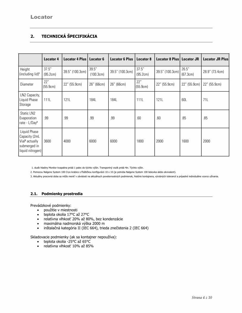
40
HNPNOM7HNKOMN8
1. dusík hladiny Monitor kvapalina pridá 1 palec do týchto výšin. Transportný vozík pridá 4in. Týchto výšin.
2. Pomocou Nalgene System 100 Cryo krabice s fľaštičkou konfigurácii 10 x 10 (je potreba Nalgene System 100 liekovka alebo ekvivalent).
3. Aktuálny pracovná doba sa môže meniť v závislosti na aktuálnych poveternostných podmienok, histórie kontajnera, výrobných tolerancií a prípadné individuálne vzorce užívania.
71(0+1
-* 6
• #• EF#EF• $ .O#KO&* *"• B /0 • 0+ 1GPP;PQFDDJ<&*+;PQFDDJ<
A " ; #$<6
• 7LEF#DLEF• $ .O#KLO
Locator 4 Locator 4 Plus Locator 6 Locator 6 Plus Locator 8 Locator 8 Plus Locator JR Locator JR Plus
Height(including lid)1
37.5” (95.2cm)
39.5” (100.3cm) 39.5”(100.3cm)
39.5” (100.3cm) 37.5” (95.2cm)
39.5” (100.3cm) 26.5” (67.3cm)
28.9” (73.4cm)
Diameter 22”(55.9cm) 22” (55.9cm) 26” (66cm) 26” (66cm) 22”
(55.9cm) 22” (55.9cm) 22” (55.9cm) 22” (55.9cm)
LN2 Capacity,Liquid PhaseStorage
111L 121L 184L 184L 111L 121L 60L 71L
Static LN2Evaporationrate - L/Day3
.99 .99 .99 .99 .60 .60 .85 .85
Liquid PhaseCapacity (2mLVial2 actuallysubmerged inliquid nitrogen)
3600 4000 6000 6000 1800 2000 1600 2000
50
8F78<Q8RHH
A "$ $ .# /0/ &,
R+00 $ "$" "" )(S "'.' $ /( / % +/* )$" ' & + )# . 0 0 " (-" . & 0 *,F1?@0AE6>1. +.D8$ * #. &$* $%(8*$ '# "&$% *%0(7+6&@1&C.1B 4S?.+&0(-6;(9:B+C1@D- $ # ' ( 8 $ /" % %/"* 0 %$(
Vyhnite sa použitie nadmernej sily pri presune nádoby; to môže spôsobujú sklápacie, čo vedie k poškodeniu a / alebo rozliatiu kvapalného dusíka. -$ $* '+. /$ .+ % /"$/".' ( /".' $0 *$/"" 0"! "& $%$(
60
$ 7H<M3GO8
$ .+E6(4?
• ? 53 ; + B *+' < , 8/0
$ #/ . 00 6o L"9"J9"Ko L"9"o LL"9"J-&9"D-9"K-o M"9"-
• 7 (+4? @( @ .=CA +.B ( >0 +E (+4?
1C&1(@F@0@60B&B;(+(04((O&1(41>0(9:+9>B.C>?+- 6(9:B+C14:@D
• (+@>0>@4=+D8 /"/+ <(" /" * * ,
• 8 /$ 7)$0 (
• A "$ $ .# / &,
$ 7@
8$#53 /$ &#.0 "& 0 0 6
• 4 3# $ &""L#(• :" # $ . "" ( + / "
/* /"* $ $ (
• - @0$"""L $ (
• :" *.JK$ $ " (
• 43 $ % ( ? 53 ; +B*+'<,:*'#+.$ #$ +,
• A ( - $ " / $ ". * + (
$ L(:+6&1-
: $ #' (:#$'+ $ (T3 *+ $(8%# . $ (
70
$$ F1.+0(+
• 8 + * #(• 2/0 " + /";=/0 U=<(
• :3 /$ =/0 U=(
• > ( - $ + + /"
"*$"$(8* ' $ "*' $ (
$# I
0+ ++ +/ /* (
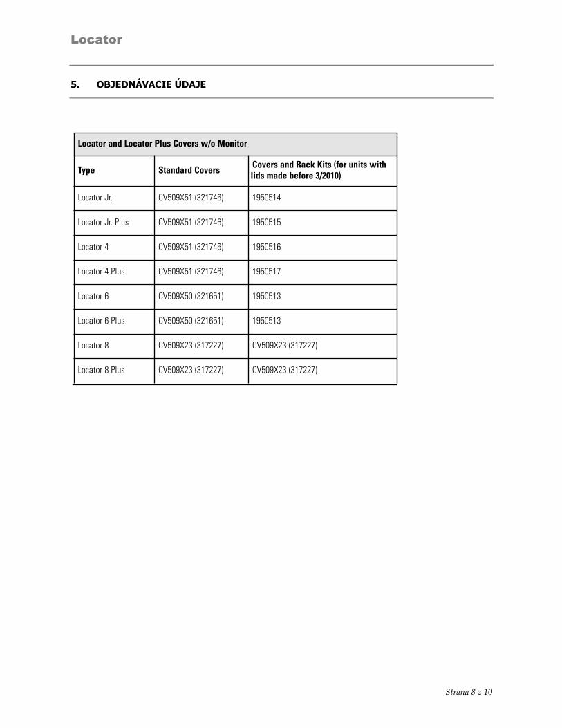
80
# TH3M<8NHU38TH
Locator and Locator Plus Covers w/o Monitor
Type Standard Covers Covers and Rack Kits (for units withlids made before 3/2010)
Locator Jr. CV509X51 (321746) 1950514
Locator Jr. Plus CV509X51 (321746) 1950515
Locator 4 CV509X51 (321746) 1950516
Locator 4 Plus CV509X51 (321746) 1950517
Locator 6 CV509X50 (321651) 1950513
Locator 6 Plus CV509X50 (321651) 1950513
Locator 8 CV509X23 (317227) CV509X23 (317227)
Locator 8 Plus CV509X23 (317227) CV509X23 (317227)
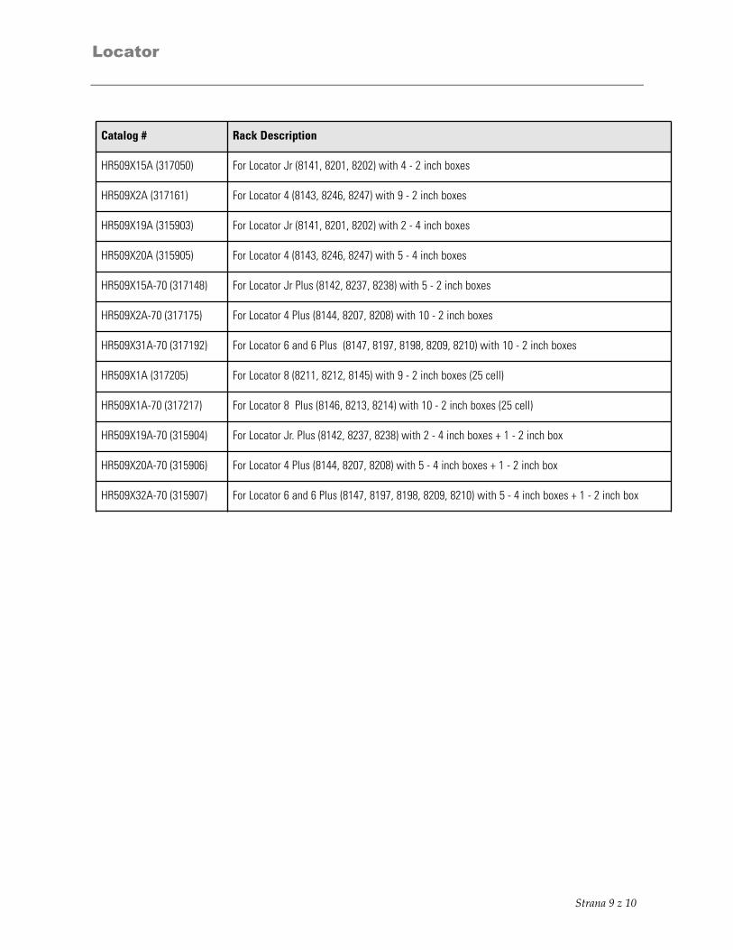
90
Catalog # Rack Description
HR509X15A (317050) For Locator Jr (8141, 8201, 8202) with 4 - 2 inch boxes
HR509X2A (317161) For Locator 4 (8143, 8246, 8247) with 9 - 2 inch boxes
HR509X19A (315903) For Locator Jr (8141, 8201, 8202) with 2 - 4 inch boxes
HR509X20A (315905) For Locator 4 (8143, 8246, 8247) with 5 - 4 inch boxes
HR509X15A-70 (317148) For Locator Jr Plus (8142, 8237, 8238) with 5 - 2 inch boxes
HR509X2A-70 (317175) For Locator 4 Plus (8144, 8207, 8208) with 10 - 2 inch boxes
HR509X31A-70 (317192) For Locator 6 and 6 Plus (8147, 8197, 8198, 8209, 8210) with 10 - 2 inch boxes
HR509X1A (317205) For Locator 8 (8211, 8212, 8145) with 9 - 2 inch boxes (25 cell)
HR509X1A-70 (317217) For Locator 8 Plus (8146, 8213, 8214) with 10 - 2 inch boxes (25 cell)
HR509X19A-70 (315904) For Locator Jr. Plus (8142, 8237, 8238) with 2 - 4 inch boxes + 1 - 2 inch box
HR509X20A-70 (315906) For Locator 4 Plus (8144, 8207, 8208) with 5 - 4 inch boxes + 1 - 2 inch box
HR509X32A-70 (315907) For Locator 6 and 6 Plus (8147, 8197, 8198, 8209, 8210) with 5 - 4 inch boxes + 1 - 2 inch box
00
F8P!
H<VGH3WRHXJ7OQQ7H5XV<8HY8 GM5IJ73LHOQ HG7HIFJKLMNH $
(( 2Z?94:[P:\HIZFPQ (((((((((((((((((((((((((((((((((((((((((((((((((((((((((((((((((((((((((((((((((((((((((((((((((((((((((((((((((( J(( XQ2-Q]:HA:[P:\HIZFPQ>-H2HI:Q:P((((((((((((((((((((((((((((((((((((((((((((((((((((((((((((((((((((((((((((((((((((((( J
HNPNOM7HNKOMN8 #(( -H4PQ:?V-IHAIQ4P (((((((((((((((((((((((((((((((((((((((((((((((((((((((((((((((((((((((((((((((((((((((((((((((((((((((((((((((( L
8F78<Q8RHH "$ 7H<M3GO8Z
J(( XQ2-Q]:HA:[P:\HIZFPQ(((((((((((((((((((((((((((((((((((((((((((((((((((((((((((((((((((((((((((((((((((((((((((((((((((((((((((( J(( -9:Q:PQ?H::QI (((((((((((((((((((((((((((((((((((((((((((((((((((((((((((((((((((((((((((((((((((((((((((((((((((((((((((((((((((( J(M( QI:PQ:H^A8?8-9:[SH4>A_?((((((((((((((((((((((((((((((((((((((((((((((((((((((((((((((((((((((((((((((((((((((((((( J(J( A?94H8:PQ82HIPQ?8-9V::HA?>-Q:A8Q ((((((((((((((((((((((((((((((((((((((((((((((((((((((((((((((((((((((((((((((((((( KJ(L( ]PAQ:PQ(((((((((((((((((((((((((((((((((((((((((((((((((((((((((((((((((((((((((((((((((((((((((((((((((((((((((((((((((((((((((((((((((((( K
# TH3M<8NHU38TH'
thermoscientific.com
© 2014 Thermo Fisher Scientific Inc. All rights reserved. All trademarks are the property of Thermo Fisher Scientific and itssubsidiaries. Specifications, termsand pricing are subject to change. Not all products are available in all countries. Please consult your local sales representativefor details.
Thermo Fisher Scientific (Asheville) LLC401 Millcreek RoadMarietta, Ohio 45750
United States
A Thermo Fisher Scientific Brand
Top Related