


![GESTIÓN DE TELECOMUNICACIONES - IntroducciónPD] Documentos... · SDH, ATM, DWDM Accesos xDSL, LMDS ... Eficiencia en la introducción de nuevos servicios y tecnologías a precios](https://static.fdocuments.net/doc/165x107/5a78ed927f8b9a5a148dd10d/gestin-de-telecomunicaciones-pd-documentossdh-atm-dwdm-accesos-xdsl-lmds.jpg)


Languages
Pages
Legal

7/16/2019 Lmds Introduction
http://slidepdf.com/reader/full/lmds-introduction 1/17
LMDSLMDS(A NEW ADVANCEMENT IN(A NEW ADVANCEMENT IN
WIRELESS COMMUNICATION)WIRELESS COMMUNICATION)GROUP MEMBERSGROUP MEMBERS
1)1) Shrikant SundaramShrikant Sundaram
2)2) Arnab DeyArnab Dey3)3) Rahul KaulRahul Kaul
4)4) Shardul vaidyaShardul vaidya
NAME OF ORGANISATIONNAME OF ORGANISATION: RELIANCE INFOCOM: RELIANCE INFOCOM
RESEARCH CENTRERESEARCH CENTRE
CHEMBUR,MUM-71CHEMBUR,MUM-71
EXTERNAL GUIDEEXTERNAL GUIDE: MR.GOVIND CHOUDHARY: MR.GOVIND CHOUDHARY
INTERNAL GUIDEINTERNAL GUIDE: PROF.G.R SREENIVASAN: PROF.G.R SREENIVASAN
Roll nosRoll nos
1)1) 43544354
2)2) 431843183)3) 43314331
4)4) 43604360
7/16/2019 Lmds Introduction
http://slidepdf.com/reader/full/lmds-introduction 2/17
CONTENTSCONTENTS
GENERAL OVERVIEWGENERAL OVERVIEW
INSTALLATIONINSTALLATION
INSTALLATION FLOWINSTALLATION FLOW AIR LINK SETUP AT BASE STATIONAIR LINK SETUP AT BASE STATION
AIR LINK SETUP AT TERMINAL STATIONAIR LINK SETUP AT TERMINAL STATION
7/16/2019 Lmds Introduction
http://slidepdf.com/reader/full/lmds-introduction 3/17
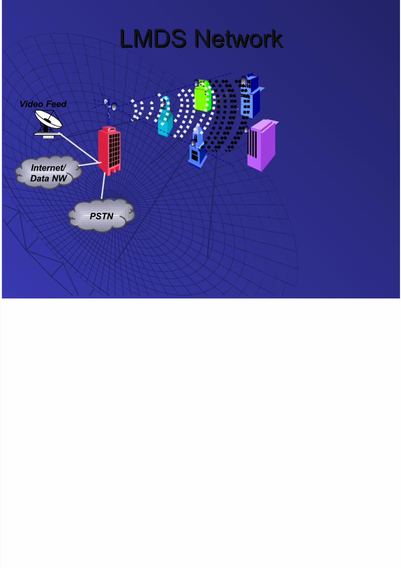
LMDS NetworkLMDS Network
Internet/
Data NW
PSTN
S a t e l l i t e d i s h
Video Feed
7/16/2019 Lmds Introduction
http://slidepdf.com/reader/full/lmds-introduction 4/17
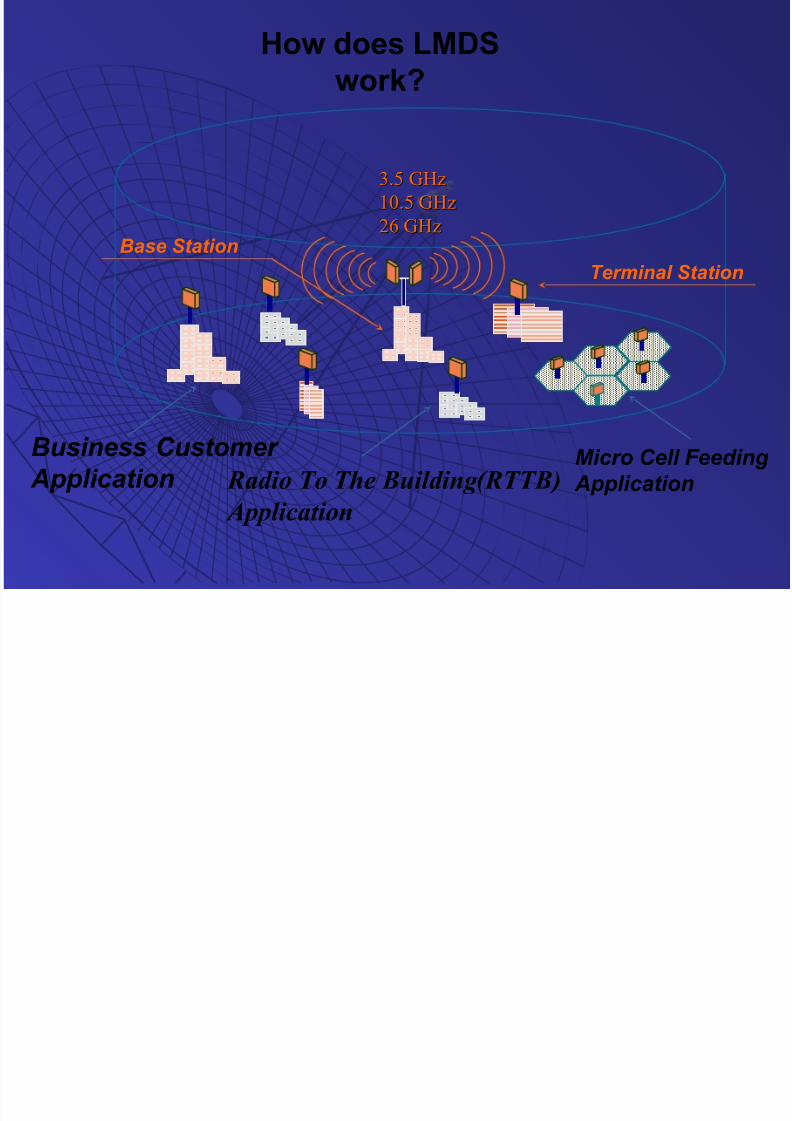
Radio To The Building(RTTB)
Application
3.5 GHz3.5 GHz
10.5 GHz10.5 GHz
26 GHz26 GHz
Business Customer
Application
Base Station
Terminal Station
Micro Cell Feeding
Application
How does LMDS
work?

7/16/2019 Lmds Introduction
http://slidepdf.com/reader/full/lmds-introduction 5/17
Air Link Setup Air Link Setup
Walker
Install Base StationSelect Frequency
Enable BU
Send Search MassagesAllocate EOC
Register Terminal StationsDefine Services
Install Terminal StationEnable BU
Frequency Scan Power EqualizationSynchronizationAuthentication
DistanceMeasurement
Equalizer TrainingSend TS ParametersOperational Service
Automatic
Process
AutomaticProcess
BaseBase
StatioStatio
nn
TerminaTermina
l Stationl Station

7/16/2019 Lmds Introduction
http://slidepdf.com/reader/full/lmds-introduction 6/17
Air Link Setup – Base Air Link Setup – Base
Installing base station and frequency selection
As the BS BU enabled and frequency is selected, a PRBSAs the BS BU enabled and frequency is selected, a PRBS
is transmitted on the desired channel, resulting ais transmitted on the desired channel, resulting a
continues 1.75 MHz of bandwidth radio signal, as if trafficcontinues 1.75 MHz of bandwidth radio signal, as if traffic
is transmitted.is transmitted.
Configuration:
• List of associated terminal stationsList of associated terminal stations
• Services (Not mandatory for link establishing)Services (Not mandatory for link establishing)
7/16/2019 Lmds Introduction
http://slidepdf.com/reader/full/lmds-introduction 7/17
Air Link Setup - Base Air Link Setup - Base
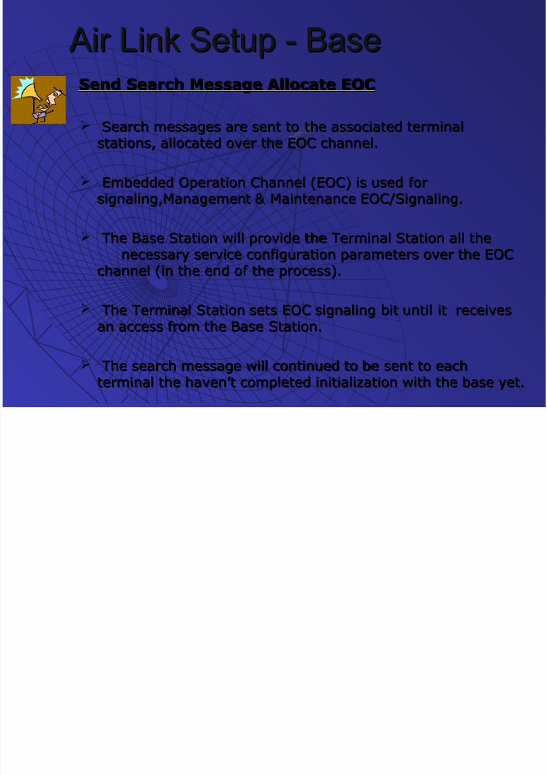
Send Search Message Allocate EOCSend Search Message Allocate EOC
Search messages are sent to the associated terminalSearch messages are sent to the associated terminal
stations, allocated over the EOC channel.stations, allocated over the EOC channel.
Embedded Operation Channel (EOC) is used forEmbedded Operation Channel (EOC) is used for
signaling,Management & Maintenance EOC/Signaling.signaling,Management & Maintenance EOC/Signaling.
The Base Station will provide the Terminal Station all theThe Base Station will provide the Terminal Station all the
necessary service configuration parameters over the EOCnecessary service configuration parameters over the EOC
channel (in the end of the process).channel (in the end of the process).
The Terminal Station sets EOC signaling bit until it receivesThe Terminal Station sets EOC signaling bit until it receives
an access from the Base Station.an access from the Base Station.
The search message will continued to be sent to eachThe search message will continued to be sent to each
terminal the haven’t completed initialization with the base yet.terminal the haven’t completed initialization with the base yet.
7/16/2019 Lmds Introduction
http://slidepdf.com/reader/full/lmds-introduction 8/17
INSTALLING THE
TERMINALSTATION
7/16/2019 Lmds Introduction
http://slidepdf.com/reader/full/lmds-introduction 9/17
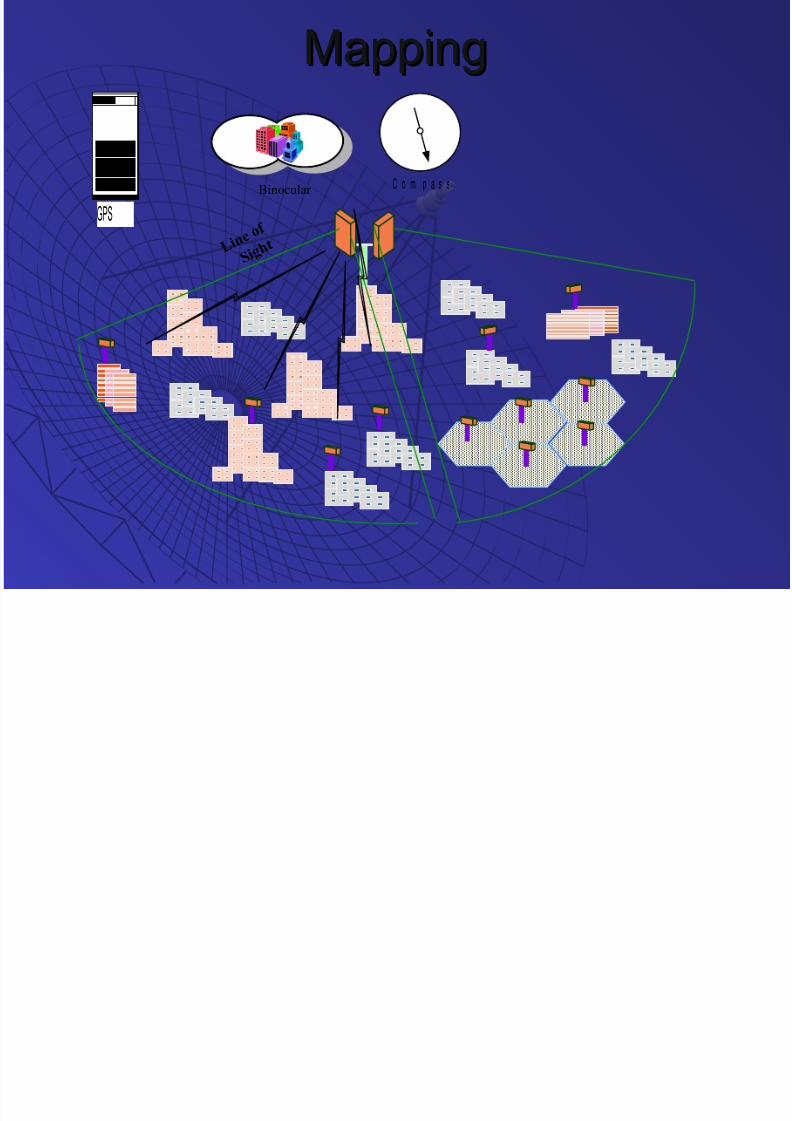
MappingMapping
C o m p a s sBinocular
L i n e o
f
S i g h t
GPS
7/16/2019 Lmds Introduction
http://slidepdf.com/reader/full/lmds-introduction 10/17
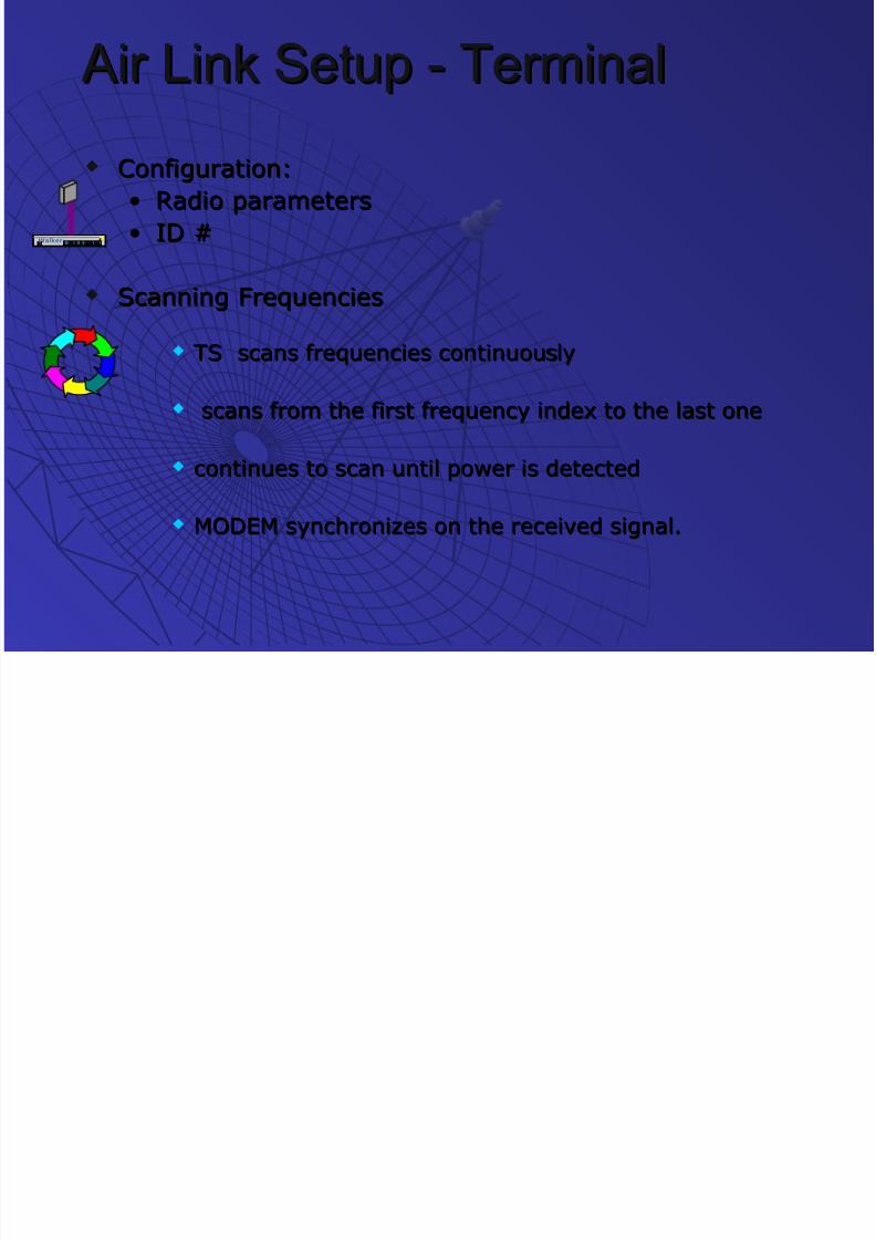
Air Link Setup - Terminal Air Link Setup - Terminal
Configuration:Configuration:
• Radio parametersRadio parameters
• ID #ID #
Scanning FrequenciesScanning Frequencies
TS scans frequencies continuouslyTS scans frequencies continuously
scans from the first frequency index to the last onescans from the first frequency index to the last one
continues to scan until power is detectedcontinues to scan until power is detected
MODEM synchronizes on the received signal.MODEM synchronizes on the received signal.
Walker
7/16/2019 Lmds Introduction
http://slidepdf.com/reader/full/lmds-introduction 11/17
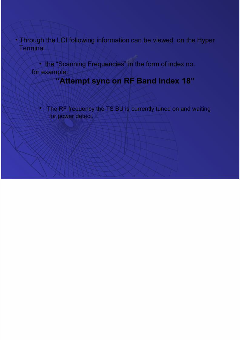
• Through the LCI following information can be viewed on the Hyper Terminal
• the “Scanning Frequencies” in the form of index no.
for example:
“Attempt sync on RF Band Index 18”
• The RF frequency the TS BU is currently tuned on and waiting
for power detect.

7/16/2019 Lmds Introduction
http://slidepdf.com/reader/full/lmds-introduction 12/17
EVENT scenarios:
Long no power
Pwr detect
Sync fail
Rx ready
7/16/2019 Lmds Introduction
http://slidepdf.com/reader/full/lmds-introduction 13/17
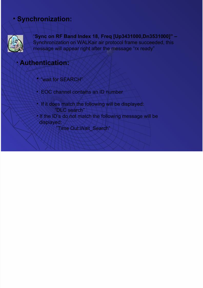
• Synchronization:
“Sync on RF Band Index 18, Freq [Up3431000,Dn3531000]” – Synchronization on WALKair air protocol frame succeeded, this
message will appear right after the message “rx ready”
• Authentication:
• “wait for SEARCH”
• EOC channel contains an ID number
• If it does match the following will be displayed:
”DLC search”• If the ID’s do not match the following message will be
displayed:
”Time Out:Wait_Search”

7/16/2019 Lmds Introduction
http://slidepdf.com/reader/full/lmds-introduction 14/17
Power EqualizationPower Equalization
Transmits a initial low power signal.Transmits a initial low power signal.
TS increases or decreases the transmitted power.TS increases or decreases the transmitted power.
RTPC process – Remote Transmit Power Control.RTPC process – Remote Transmit Power Control.
Distance measurementDistance measurement
The BS BU is measuring the distance to the TS BU.The BS BU is measuring the distance to the TS BU.
This process happens only during the initializationThis process happens only during the initialization
phase.phase. In the end of the measurement the following will beIn the end of the measurement the following will be
displayed:displayed: “Estimated dist: 0 Adjustment: 0 “Estimated dist: 0 Adjustment: 0
symbols. (Debug Init Dist: 0)”; “DLC distance “;symbols. (Debug Init Dist: 0)”; “DLC distance “;
“DISTANCE –8”. “DISTANCE –8”.
7/16/2019 Lmds Introduction
http://slidepdf.com/reader/full/lmds-introduction 15/17
Air Link Setup – Terminal Air Link Setup – Terminal Equalizer TrainingEqualizer Training
• Reads path characteristicsReads path characteristics
• Automatic and continues as long as the link is up.Automatic and continues as long as the link is up.
TS Sends ParametersTS Sends Parameters
Operational ServiceOperational Service
• All the required services are enabled.All the required services are enabled.
7/16/2019 Lmds Introduction
http://slidepdf.com/reader/full/lmds-introduction 16/17
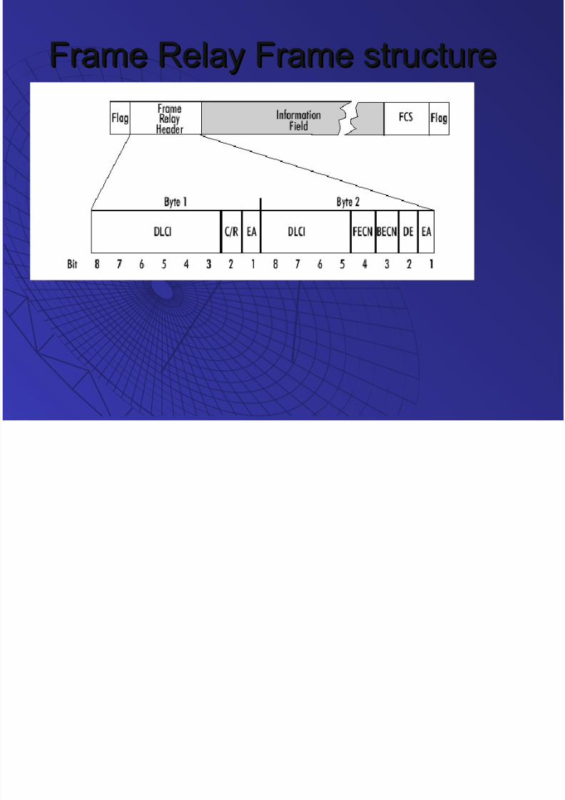
Frame Relay Frame structureFrame Relay Frame structure

7/16/2019 Lmds Introduction
http://slidepdf.com/reader/full/lmds-introduction 17/17
GROUP MEMBERSGROUP MEMBERS
Shrikant SundaramShrikant Sundaram
Arnab DeyArnab Dey
Rahul KaulRahul Kaul
Shardul vaidyaShardul vaidya
NAME OFNAME OF
ORGANISATIONORGANISATION::
RELIANCE INFOCOMRELIANCE INFOCOM
RESEARCH CENTRERESEARCH CENTRE
CHEMBUR,MUM-71CHEMBUR,MUM-71EXTERNAL GUIDEEXTERNAL GUIDE::
MR.GOVIND CHOUDHARYMR.GOVIND CHOUDHARY
INTERNAL GUIDEINTERNAL GUIDE::
PROF.G.R SREENIVASANPROF.G.R SREENIVASAN
Top Related