


Languages
Pages
Legal

Literature Study on Condition of Tertiary of
Interbus Transformer and Alternative Protection
Joko Muslim, Didik F. Dakhlan, Arrester C. S. Rahayu, and Satyagraha A. Kadir PLN Indonesia, Jakarta, Indonesia
Email: {joko.muslim, didik.fauzi, arrester, satyagraha}@pln.co.id
Abstract—Interbus Transformer (IBT) plays important role
in the reliability of power system interconnecting two
different voltage levels thus enable the power interchange.
Failure in the IBTs’ bushings, will instantly lead to the
power interruption and outage. Normally, IBTs are
constructed of three windings with primary and secondary
in wye and the tertiary in delta. The primary and secondary
are loaded, with tertiary mostly unloaded and provide the
isolating system due to the unbalance from the other two
windings. Operating bushings above the nominal voltage
tends to reduce the operating cycle. Displacement of
absolute reference from phase to phase voltage thus will
raise the applied voltage exceeds the nominal voltage.
Theoretically, applying operating voltage of 1.571 x U0 to
the tertiary bushing continuously is likely to reduce the life
time of bushing to approximately 2.5 years. Online
monitoring technique is introduced to monitor the changes
in the bushings due to the degradation of insulation quality.
Literature study focusing on the ideal condition of a bushing
against the real loading cycle in operation also considered to
estimate the insulation degradation mechanism. This study
put more efforts in analyzing the bushing condition as the
function of loading pattern and the applied voltage. Bushing
online monitoring data are attached as well to describe the
occurrences inside the bushing. At the end of this study,
options on the protection scheme are described with fault
analysis.
Index Terms—tertiary bushing, partial discharge, expected
life time, protection scheme
I. INTRODUCTION
Generally the existence of tertiary windings in
transformer enable the path to the current circulation in
the winding itself when the unbalanced conditions occur
both in normal operation or fault circumstances. Tertiary
windings enhanced the more compact, simple and
economics design of transformers. Practically, the tertiary
windings play roles as [1]:
To reduce triple harmonic of output voltage
thereby stabilizing potential of the neutral point.
To suppress third harmonic current.
To provide path of circulation current in unbalance
condition.
To reduce the system zero sequence impedance in
effective earthing where solid earthing is not
provided.
Manuscript received August 19, 2014; revised August 30, 2015.
To supply the auxiliary loads.
In PLN it is a common practice to utilize the single
phase single bank interbus transformers (IBTs) for 500kV,
with few of three phase single bank IBT. Total of 135
unit of IBTs are in operation at voltage level of
500/150kV with tertiary winding to deliver the power
from 500kV to 150kV power grid with detail as Table I
[2].
TABLE I. TYPE AND NUMBER OF INTERBUS TRANSFORMER
No. Interbus Transformer Tertiary Earthing Total
1. Three phase single bank Solid 3
2. Single phase single bank Solid 26
3. Single phase single bank Floating 18
During the operation, several failures and damages on
were recorded. Table II shows the event recorded during
period of 2008 up to 2013 on IBTs 500/150kV. The
failure of IBT results in unexpected large area blackout
and huge losses of economics and social potential in the
community. It is necessary to continuously observe the
condition of IBTs and run a life cycle estimation to avoid
the occurrence of this unexpected event so the future
action can be precisely planned in precaution.
TABLE II. IBTS FAILURE STATISTICS IN JAVA BALI SYSTEM
No. IBT
Identity Year of
Operation Year of Failure
Cause
1. CW1 ph R 1996 2009 Bushing
2. KB1 ph T 1994 2009 Secondary Bushing
3. CB2 ph R 2012 2012 Tertiary Bushing
4. CW2 ph S 1996 2013 Tertiary Bushing
II. BUSHING AND ITS STANDARDS
Referred to IEC 60137 [3], bushing is defined as
device the enables one or several conductors to pass
through a partition such as a wall or a tank, and insulates
the conductors from it. Bushings experience the highest
stress compared to other parts of a transformer. Part of
bushing that suffered the highest potential gradient is part
that close to the enclosure/tank of the transformer or parts
that is directly earthed.
The contribution of bushings failure to the transformer
damaged range from 12.3%-20% according to CIGRE
1983 statistic. This statistic is higher in PLN as describe
in Table II above.
International Journal of Electronics and Electrical Engineering Vol. 4, No. 3, June 2016
©2016 Int. J. Electron. Electr. Eng. 215doi: 10.18178/ijeee.4.3.215-220

A. Tertiary Winding Connection
The IBTs 500/150/66kV in PLN are commonly
connected in delta for the tertiary winding and solidly
earthed as shown in Fig. 1 and Fig. 2. The rated voltage
of tertiary winding is 66kV.
Figure 1. Tertiary connected in Delta in IBTs.
Figure 2. Equivalent circuit and the vector.
In vector analysis, the tertiary winding can be redrawn
in the following equivalent circuit. In the unearthed delta
circuit, the phase-to-phase voltages of each phase are
66kV without phase-to-earth reference. The 66kV is the
relative voltage between phases. No absolute reference in
this connection. The apparent reference as if the neutral
point is in the center of the delta, shown in the blue dash
line. When the connection between phase S and T is
drawn solidly earthed, then the absolute reference is now
appear and the apparent neutral point displace to the
connection point between phase S and T. The relative
voltage of 66kV at phase S and T now turn to be the
absolute voltage.
B. Bushing Specification
Most of the bushings assembled to the tertiary winding
are rated at 72.5kV with the specification as shown in
Table III.
TABLE III. SPECIFICATION OF TERTIARY BUSHING
No. Item Remark
1. Type Not mentioned
2. Highest voltage (Um) 72.5kV
3. Maximum phase to earth voltage 42kV
4. Bushing Dry Power frequency voltage withstand (AC)
155kV
5. Transformer Power frequency voltage
withstand (AC)
140kV
6. Lightning Impulse withstand voltage (BIL)
325kV
7. Rated current (Ir) 800/1000/1250/1600/2500/3150A
8. AD Arcing distance (min.) 600mm
9. Standard creepage distance 1820mm
C. Online Bushing Monitoring
Online bushing monitoring installed in IBT is a
Dynamic Rating type DTM-6 (see Fig. 3). The monitored
parameters are:
Temperature
Bushing power factor
Bushing capacitance
Bushing partial discharge
Figure 3. Test/Potential tap of bushing and installed DTM-6.
The principle of DTM-6 is sum the currents measured
from the bushing via the test/potential tap (Table III).
This sum of current method calculates relative variance
of capacitance and power factor of each bushing.
The online bushing monitoring data were taken from
DTM-6 installed at on IBT 500/150/66kV at CW SS,
Jakarta, with the following measurement on two bushings
of each phase of tertiary winding:
Channel 7 (CH07) TV1 Bushing phase R (Tertiary)
Channel 8 (CH08) TV1 Bushing phase S (Tertiary)
Channel 9 (CH09) TV1 Bushing phase T (Tertiary)
Channel 10 (CH010) TV2 Bushing phase R
(Tertiary)
Channel 11 (CH011) TV2 Bushing phase S
(Tertiary)
Channel 12 (CH012) TV2 Bushing phase T
(Tertiary)
The measurement data on primary and secondary
winding will not be concerned further since this study
focus on the tertiary winding.
III. DATA AND LITERATURE STUDY
Due to the lack of supporting data from the routine
maintenance and online monitoring prior to 2012, this
project is focused on the literature study with the empiric
and some theoretical approach. Data from online
monitoring measurements are applied as comparison
variable whether there are changes in diagnostic
parameters.
A. Online Monitoring
The bushing online monitoring data is achieved from
DTM-6 recorder with observed parameter:
Imbalanced current
Tan δ and capacitance of bushing
Changes of load current, temperature, humidity as
reference
Partial discharge
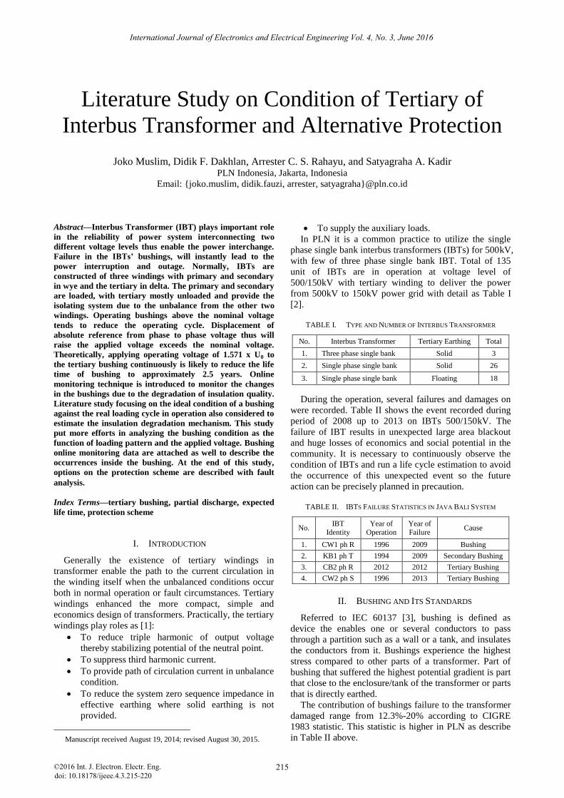
Fig. 4 shows the record of Tan δ parameter taken in the
period of June 18th
-20th, 2013. Areas marked with yellow,
green and red respectively show the abnormalities
measurement of Tan δ phase R, S and T.
International Journal of Electronics and Electrical Engineering Vol. 4, No. 3, June 2016
©2016 Int. J. Electron. Electr. Eng. 216
The abnormality of bushing is associated to the phase
due to unbalanced current encountering related area.
Unbalanced current was 1.87% and 28.69°, which is
below the critical value of 3% [4].
Figure 4. Tan δ online monitoring.
Fig. 5 shows record of capacitance parameter taken
from the same period as the Tan δ parameter. Lines
marked with yellow, green, red, purple and blue
respectively show capacitance measurement of bushing
tertiary phase R, S and T, the temperature and humidity
of the ambient condition. There were not significant
changes associated to the deviation of temperature and
humidity. The capacitance parameters show relatively
stable reading at 411pF, 383pF and 338pF each phases.
Figure 5. Capacitance online monitoring.
Figure 6. PD online monitoring on tertiary bushings 3.1.
Fig. 6 shows the record of PD activities during longer
period on tertiary bushings 3.1. Lines marked by purple,
grey, green, blue and red respectively refer to bushing 3.1
phase R, S, T and measurement of humidity and
temperature of ambient condition of these bushings.
At certain time interval, bushing 3.1 at phase R shows
significant PD activities compare with the other bushings.
The lowest PD activities was recorded at bushing T.
instead of to display the quantitative measurement, PD
activity records show the existence of PD activity itself in
the associated bushing.
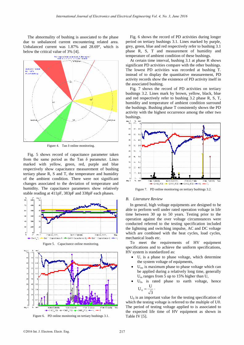
Fig. 7 shows the record of PD activities on tertiary
bushings 3.2. Lines mark by brown, yellow, black, blue
and red respectively refer to bushing 3.2 phase R, S, T,
humidity and temperature of ambient condition surround
the bushings. Bushing phase T consistently shows the PD
activity with the highest occurrence among the other two
bushings.
Figure 7. PD online monitoring on tertiary bushings 3.2.
B. Literature Review
In general, high voltage equipments are designed to be
able to perform well under rated operation voltage in life
time between 30 up to 50 years. Testing prior to the
operation against the over voltage circumstances were
conducted referred to the testing specification included
the lightning and switching impulse, AC and DC voltage
which are combined with the heat cycles, load cycles,
mechanical loads etc.
To meet the requirements of HV equipment
specifications and to achieve the uniform specifications,
HV system is standardized as:
U, is a phase to phase voltage, which determine
the system voltage of equipments,
Um, is maximum phase to phase voltage which can
be applied during a relatively long time, generally
Um ranges from 5 up to 15% higher than U,
U0, is rated phase to earth voltage, hence
3
UU 0 .
U0 is an important value for the testing specification of
which the testing voltage is referred to the multiple of U0.
The period of testing voltage applied to is associated to
the expected life time of HV equipment as shown in
Table IV [5].
International Journal of Electronics and Electrical Engineering Vol. 4, No. 3, June 2016
©2016 Int. J. Electron. Electr. Eng. 217
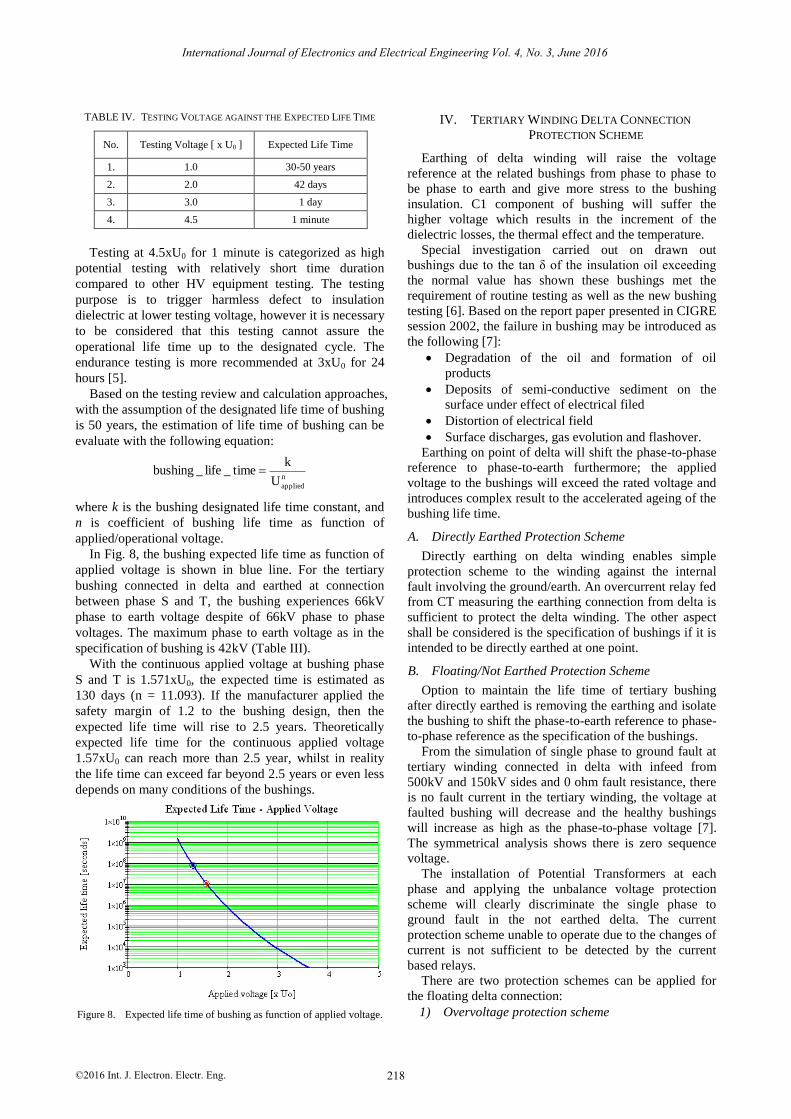
TABLE IV. TESTING VOLTAGE AGAINST THE EXPECTED LIFE TIME
No. Testing Voltage [ x U0 ] Expected Life Time
1. 1.0 30-50 years
2. 2.0 42 days
3. 3.0 1 day
4. 4.5 1 minute
Testing at 4.5xU0 for 1 minute is categorized as high
potential testing with relatively short time duration
compared to other HV equipment testing. The testing
purpose is to trigger harmless defect to insulation
dielectric at lower testing voltage, however it is necessary
to be considered that this testing cannot assure the
operational life time up to the designated cycle. The
endurance testing is more recommended at 3xU0 for 24
hours [5].
Based on the testing review and calculation approaches,
with the assumption of the designated life time of bushing
is 50 years, the estimation of life time of bushing can be
evaluate with the following equation:
n
appliedU
ktime_life_bushing
where k is the bushing designated life time constant, and
n is coefficient of bushing life time as function of
applied/operational voltage.
In Fig. 8, the bushing expected life time as function of
applied voltage is shown in blue line. For the tertiary
bushing connected in delta and earthed at connection
between phase S and T, the bushing experiences 66kV
phase to earth voltage despite of 66kV phase to phase
voltages. The maximum phase to earth voltage as in the
specification of bushing is 42kV (Table III).
With the continuous applied voltage at bushing phase
S and T is 1.571xU0, the expected time is estimated as
130 days (n = 11.093). If the manufacturer applied the
safety margin of 1.2 to the bushing design, then the
expected life time will rise to 2.5 years. Theoretically
expected life time for the continuous applied voltage
1.57xU0 can reach more than 2.5 year, whilst in reality
the life time can exceed far beyond 2.5 years or even less
depends on many conditions of the bushings.
Figure 8. Expected life time of bushing as function of applied voltage.
IV. TERTIARY WINDING DELTA CONNECTION
PROTECTION SCHEME
Earthing of delta winding will raise the voltage
reference at the related bushings from phase to phase to
be phase to earth and give more stress to the bushing
insulation. C1 component of bushing will suffer the
higher voltage which results in the increment of the
dielectric losses, the thermal effect and the temperature.
Special investigation carried out on drawn out
bushings due to the tan δ of the insulation oil exceeding
the normal value has shown these bushings met the
requirement of routine testing as well as the new bushing
testing [6]. Based on the report paper presented in CIGRE
session 2002, the failure in bushing may be introduced as
the following [7]:
Degradation of the oil and formation of oil
products
Deposits of semi-conductive sediment on the
surface under effect of electrical filed
Distortion of electrical field
Surface discharges, gas evolution and flashover.
Earthing on point of delta will shift the phase-to-phase
reference to phase-to-earth furthermore; the applied
voltage to the bushings will exceed the rated voltage and
introduces complex result to the accelerated ageing of the
bushing life time.
A. Directly Earthed Protection Scheme
Directly earthing on delta winding enables simple
protection scheme to the winding against the internal
fault involving the ground/earth. An overcurrent relay fed
from CT measuring the earthing connection from delta is
sufficient to protect the delta winding. The other aspect
shall be considered is the specification of bushings if it is
intended to be directly earthed at one point.
B. Floating/Not Earthed Protection Scheme
Option to maintain the life time of tertiary bushing
after directly earthed is removing the earthing and isolate
the bushing to shift the phase-to-earth reference to phase-
to-phase reference as the specification of the bushings.
From the simulation of single phase to ground fault at
tertiary winding connected in delta with infeed from
500kV and 150kV sides and 0 ohm fault resistance, there
is no fault current in the tertiary winding, the voltage at
faulted bushing will decrease and the healthy bushings
will increase as high as the phase-to-phase voltage [7].
The symmetrical analysis shows there is zero sequence
voltage.
The installation of Potential Transformers at each
phase and applying the unbalance voltage protection
scheme will clearly discriminate the single phase to
ground fault in the not earthed delta. The current
protection scheme unable to operate due to the changes of
current is not sufficient to be detected by the current
based relays.
There are two protection schemes can be applied for
the floating delta connection:
1) Overvoltage protection scheme
International Journal of Electronics and Electrical Engineering Vol. 4, No. 3, June 2016
©2016 Int. J. Electron. Electr. Eng. 218
voltage as shown in Fig. 9. Since the floating delta is
subjected to the voltage balance, this scheme provides
more sensitivity in the single phase to ground fault even
involving high resistance.
Figure 9. Overvoltage protection scheme.
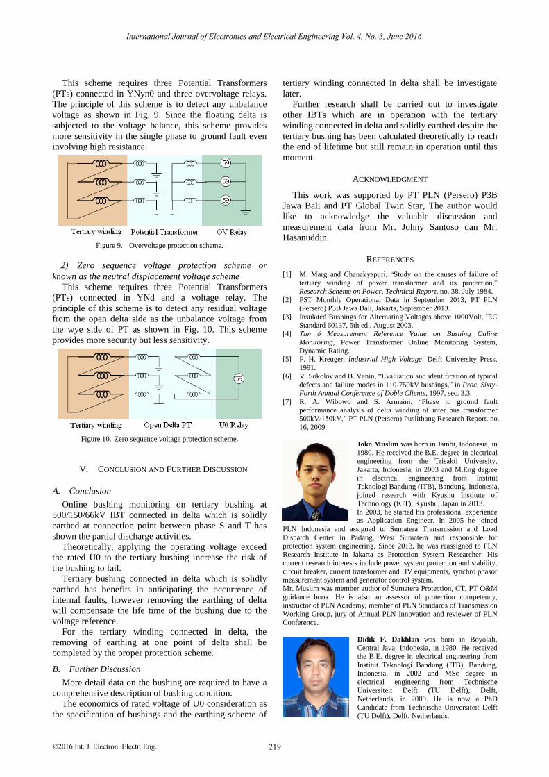
2) Zero sequence voltage protection scheme or
known as the neutral displacement voltage scheme
This scheme requires three Potential Transformers
(PTs) connected in YNd and a voltage relay. The
principle of this scheme is to detect any residual voltage
from the open delta side as the unbalance voltage from
the wye side of PT as shown in Fig. 10. This scheme
provides more security but less sensitivity.
Figure 10. Zero sequence voltage protection scheme.
V. CONCLUSION AND FURTHER DISCUSSION
A. Conclusion
Online bushing monitoring on tertiary bushing at
500/150/66kV IBT connected in delta which is solidly
earthed at connection point between phase S and T has
shown the partial discharge activities.
Theoretically, applying the operating voltage exceed
the rated U0 to the tertiary bushing increase the risk of
the bushing to fail.
Tertiary bushing connected in delta which is solidly
earthed has benefits in anticipating the occurrence of
internal faults, however removing the earthing of delta
will compensate the life time of the bushing due to the
voltage reference.
For the tertiary winding connected in delta, the
removing of earthing at one point of delta shall be
completed by the proper protection scheme.
B. Further Discussion
More detail data on the bushing are required to have a
comprehensive description of bushing condition.
The economics of rated voltage of U0 consideration as
the specification of bushings and the earthing scheme of
tertiary winding connected in delta shall be investigate
later.
Further research shall be carried out to investigate
other IBTs which are in operation with the tertiary
winding connected in delta and solidly earthed despite the
tertiary bushing has been calculated theoretically to reach
the end of lifetime but still remain in operation until this
moment.
ACKNOWLEDGMENT
This work was supported by PT PLN (Persero) P3B
Jawa Bali and PT Global Twin Star, The author would
like to acknowledge the valuable discussion and
measurement data from Mr. Johny Santoso dan Mr.
Hasanuddin.
REFERENCES
[1] M. Marg and Chanakyapuri, “Study on the causes of failure of
tertiary winding of power transformer and its protection,” Research Scheme on Power, Technical Report, no. 38, July 1984.
[2] PST Monthly Operational Data in September 2013, PT PLN (Persero) P3B Jawa Bali, Jakarta, September 2013.
[3] Insulated Bushings for Alternating Voltages above 1000Volt, IEC
Standard 60137, 5th ed., August 2003. [4] Tan δ Measurement Reference Value on Bushing Online
Monitoring, Power Transformer Online Monitoring System, Dynamic Rating.
[5] F. H. Kreuger, Industrial High Voltage, Delft University Press,
1991. [6] V. Sokolov and B. Vanin, “Evaluation and identification of typical
defects and failure modes in 110-750kV bushings,” in Proc. Sixty-Forth Annual Conference of Doble Clients, 1997, sec. 3.3.
[7] R. A. Wibowo and S. Armaini, “Phase to ground fault
performance analysis of delta winding of inter bus transformer
Joko Muslim was born in Jambi, Indonesia, in
1980. He received the B.E. degree in electrical engineering from the Trisakti University,
Jakarta, Indonesia, in 2003 and M.Eng degree in electrical engineering from Institut
Teknologi Bandung (ITB), Bandung, Indonesia,
joined research with Kyushu Institute of Technology (KIT), Kyushu, Japan in 2013.
In 2003, he started his professional experience as Application Engineer. In 2005 he joined
PLN Indonesia and assigned to Sumatera Transmission and Load
Dispatch Center in Padang, West Sumatera and responsible for protection system engineering. Since 2013, he was reassigned to PLN
Research Institute in Jakarta as Protection System Researcher. His current research interests include power system protection and stability,
circuit breaker, current transformer and HV equipments, synchro phasor
measurement system and generator control system. Mr. Muslim was member author of Sumatera Protection, CT, PT O&M
guidance book. He is also an assessor of protection competency, instructor of PLN Academy, member of PLN Standards of Transmission
Working Group, jury of Annual PLN Innovation and reviewer of PLN
Conference.
Didik F. Dakhlan was born in Boyolali, Central Java, Indonesia, in 1980. He received
the B.E. degree in electrical engineering from
Institut Teknologi Bandung (ITB), Bandung, Indonesia, in 2002 and MSc degree in
electrical engineering from Technische Universiteit Delft (TU Delft), Delft,
Netherlands, in 2009. He is now a PhD
Candidate from Technische Universiteit Delft (TU Delft), Delft, Netherlands.
International Journal of Electronics and Electrical Engineering Vol. 4, No. 3, June 2016
©2016 Int. J. Electron. Electr. Eng. 219
This scheme requires three Potential Transformers
(PTs) connected in YNyn0 and three overvoltage relays.
The principle of this scheme is to detect any unbalance
500kV/150kV,” PT PLN (Persero) Puslitbang Research Report, no.
16, 2009.
In 2002 he joined PLN Indonesia and assigned to Java Bali Transmission and Load Dispatch Center in Jakarta and responsible for
SCADA and protection system engineering. In 2010, he was assigned to
PLN Research Institute in Jakarta as Protection System Researcher and became Deputy Manager of Transmission and Distribution System
Research Planning in 2012. Since 2014, he was assigned as Deputy Manager of Protection, Installation, and Power System Laboratory. His
current research interests include power system protection and control,
power system stability, investigation of power system disturbance/failure, wide area protection and control, and generator
control system. Mr. Dakhlan is also an assessor of protection competency, instructor of
PLN Corporate University, secretary of PLN Standards of Transmission
Working Group and reviewer of PLN Conference.
Satyagraha A. Kadir was born in Karawang,
West Java, Indonesia, in 1959. He received the
B.E. degree in electrical engineering from Universitas Krisnadwipayana, Jakarta,
Indonesia, in 1997. In 1981 he joined PLN Research Institute in
Jakarta as Testing Engineer in Electrical
Apparatus Laboratory. He is involved mostly in the power transformer, power cable and
medium voltage switchgear testing. He was appointed as Manager of Research and Development of Transmission
and Distribution during 2011-2014. Presently he is a senior researcher
of electrical apparatus in PLN Research Institute. His current research interests include investigation of failure and performance electrical
apparatus. Mr. Satyagraha was jury of Annual PLN Innovation up to 2014. He is
also instructor of PLN Academy and member of PLN Standards of
Distribution Working Group.
Arrester C. S. Rahayu was born in Jakarta, Indonesia, in 1978. She received the B.E.
degree in electrical engineering from Institut
Teknologi Bandung (ITB), Bandung, Indonesia, in 2001 and MM degree in management from
Universitas Indonesia, Jakarta, Indonesia, in 2003. She is now a PhD Candidate from
Universitas Indonesia, Jakarta, Indonesia.
In 2004, she joined PLN Indonesia and was assigned to PLN Region South Sumatra, Jambi
and Bengkulu in Palembang, South Sumatra, and was responsible for distribution system and later on for Corporate Planning. In 2005, she
was stationed in PLN Distribution Jakarta Raya and Tangerang in
Corporate Planning Field. In 2006, she was transferred to PLN Head Office in Jakarta in Sub directorate Investment and Shareholders’
Ownership Management and was responsible for external funding. In 2009, she was assigned to Sub directorate Corporate Finance and was
responsible for loan administration. In 2010, she was assigned to
Human Resources and Talent Division and was responsible for leadership training. In 2011, she was assigned to PLN Research Institute
in Jakarta as transmission and distribution system researcher and energy audit and techno economy researcher in 2013. Since 2014, she was
assigned to PLN Head Office in Risk Management Division and is
responsible for risk assessment. Her current research interests include T&D system, strategic management, corporate finance, project finance,
risk management, and human resources. She was a member of PLN Standards of Distribution Working Group.
She is also a member of PLN Standards of Transmission Working
Group.
International Journal of Electronics and Electrical Engineering Vol. 4, No. 3, June 2016
©2016 Int. J. Electron. Electr. Eng. 220
Top Related