


Languages
Pages
Legal


1066 Liquid AnalyticalTransmitter
1066 Instruction ManualLIQ_MAN_1066
Rev. GDecember 2014

This page left intentionally blank

noTICE
Emerson designs, manufactures, and tests its Rosemount Analytical products to meet many
national and international standards. Because these instruments are sophisticated technical prod-
ucts, you must properly install, use, and maintain them to ensure they continue to operate within
their normal specifications. The following instructions must be adhered to and integrated into your
safety program when installing, using, and maintaining Rosemount Analytical products. Failure to
follow the proper instructions may cause any one of the following situations to occur: Loss of life;
personal injury; property damage; damage to this instrument; and warranty invalidation.
• Read all instructions prior to installing, operating, and servicing the product. If this Instruction
Manual is not the correct manual, telephone 1-800-854-8257 and the requested manual will
be provided. Save this Instruction Manual for future reference.
• If you do not understand any of the instructions, contact your Emerson representative for
clarification.
• Follow all warnings, cautions, and instructions marked on and supplied with the product.
• Inform and educate your personnel in the proper installation, operation, and maintenance of
the product.
• Install your equipment as specified in the Installation Instructions of the appropriate
Instruction Manual and per applicable local and national codes. Connect all products to the
proper electrical and pressure sources.
• To ensure proper performance, use qualified personnel to install, operate, update, program, and
maintain the product.
• When replacement parts are required, ensure that qualified people use replacement parts
specified by Rosemount. Unauthorized parts and procedures can affect the product’s
performance and place the safe operation of your process at risk. Look alike substitutions may
result in fire, electrical hazards, or improper operation.
• Ensure that all equipment doors are closed and protective covers are in place, except when main-
tenance is being performed by qualified persons, to prevent electrical shock and personal injury.
If a 475 universal hArT® Communicator is used with these transmitters, the software within the 475
may require modification. If a software modification is required, please contact your local Emerson
processs Management Service Group or national response Center at 1-800-654-7768.
WArnInG: ExpLoSIon hAzArD
Do noT opEn WhILE CIrCuIT IS LIvE. onLy CLEAn WITh DAMp CLoTh.
Electrostatic ignition hazard. Special condition for safe use (when installed in hazardous area)
1. The plastic enclosure, excepting the front panel, must only be cleaned with a damp cloth. Thesurface resistivity of the non-metallic enclosure materials is greater than one gigaohm. Caremust be taken to avoid electrostatic charge build-up. The 1066 Transmitter must not berubbed or cleaned with solvents or a dry cloth.
2. The panel mount gasket has not been tested for type of protection IP66 or Class II and III. Typeof protection IP66 and Class II, III refer the enclosure only.
Essential InstructionsRead this page before proceeding
Essential Instructions I

II
This manual contains instructions for installation and operation of the 1066 Smart Transmitter.The following list provides notes concerning all revisions of this document.
rev. Level Date notes
A 1/2012 This is the initial release of the product manual. The manual has been reformatted to reflect the Emerson documentation style and updated to reflect any changes in the product offering.
B 3/2012 This product manual version adds specifications and instrument instructions for Contacting Conductivity, Toroidal Conductivity, Chlorine, Oxygen, and Ozone measurements.
C 9/2012 This product manual version adds FM agency approval.
D 3/2013 Updated CSA Intrinsically Safe Installation drawings.
E 7/2013 Updated CSA test Standards and Intrinsically Safe installation drawings and update CE certificates. Added FM temperature specifications to Non-Incendive Hazardous Location Approval.
F 9/2013 Added Section 10: HART® Communications
G 11/2014 Changed agency water exposure testing description to “Type”.
About this document
3. The surface resistivity of the non-metallic enclosure materials is greater than one gigaohm.Care must be taken to avoid electrostatic charge build-up. The Model 1066 Transmitter mustnot be rubbed or cleaned with solvents or a dry cloth.
4. Special Condition of Use of 1066-C-FF/FI-67 and 1066-T-FF/FI-67. For use with simple appara-tus model series 140, 141, 142, 150, 400, 401, 402, 402VP, 403, 403VP, 404, and 410VP con-tacting conductivity sensors and model series 222, 225, 226, 228 toroidal sensors.
1066 Instruction Manual Table of ContentsLIQ_MAN_1066 December 2014
Contents
Section 1: Quick Start Guide1.1 Quick start guide..........................................................................................................1
Section 2: Description and Specifications2.1 Features and Applications ............................................................................................3
2.2 General specifications...................................................................................................4
2.3 pH/ORP ........................................................................................................................4
2.3.1 Performance Specifications - Transmitter (pH input) ......................................6
2.2.2 Performance Specifications - Transmitter (ORP input) ....................................6
2.4 Contacting Conductivity (Codes – C) ...........................................................................7
2.4.1 Performance Specifications.............................................................................7
2.4.2 Recommended Sensors for Conductivity .......................................................8
2.5 Toroidal Conductivity (Codes – T) ................................................................................8
2.5.1 Performance Specifications.............................................................................8
2.5.2 Recommended Sensors for Conductivity........................................................9
2.6 Chlorine (Codes – CL) ...................................................................................................9
2.6.1 Free and Total Chlorine....................................................................................9
2.6.2 Performance Specifications.............................................................................9
2.6.3 Recommended Sensors ..................................................................................9
2.6.4 Monochloromine ............................................................................................9
2.6.5 Performance Specifications...........................................................................10
2.6.6 Recommended Sensors ................................................................................10
2.7 Dissolved Oxygen (Codes – DO).................................................................................10
2.7.1 Free and Total Chlorine..................................................................................10
2.7.2 Performance Specifications...........................................................................10
2.8 Dissolved Oxygen (Codes – DO).................................................................................10
2.8.1 Free and Total Chlorine..................................................................................10
2.8.2 Performance Specifications...........................................................................10
2.9 Ordering Information .................................................................................................11
Section 3: Installation3.1 Unpacking and Inspection..........................................................................................13
3.2 Installation – general information ..............................................................................13
3.3 Preparing conduit openings .......................................................................................13
Section 4: Wiring4.1 General ...................................................................................................................... 17
4.1.1 General Information ......................................................................................17
4.1.2 Digital Communication.................................................................................17
4.2 Power Supply/Current Loop – 1066-HT......................................................................17
Table of Contents III

Table of Contents 1066 Instruction ManualDecember 2014 LIQ_MAN_1066
4.2.1 Power Supply and Load Requirements ..........................................................17
4.2.2 Power Supply-Current Loop Wiring...............................................................18
4.2.3 Current Output wiring...................................................................................19
4.3 Power Supply Wiring For 1066-FF...............................................................................19
4.3.1 Power Supply Wiring .....................................................................................19
4.4 Sensor Wiring to Main Board ......................................................................................21
Section 5: Intrinsically Safe Installation5.1 All Intrin sically Safe Installations ................................................................................27
Section 6: Display and operation6.1 User Interface.............................................................................................................37
6.2 Instrument Keypad.....................................................................................................37
6.3 Main Display ...............................................................................................................38
6.4 Menu System..............................................................................................................38
Section 7: programming – Basics7.1 General.......................................................................................................................41
7.2 Changing the Startup Settings ...................................................................................41
7.2.1 Purpose .........................................................................................................41
7.2.2 Procedure......................................................................................................42
7.3 Choosing Temperature Units & Automatic/Manual Temperature Compensation......42
7.3.1 Purpose .........................................................................................................42
7.3.2 Procedure......................................................................................................42
7.4 Contacting Conductivity Calibration..........................................................................42
7.4.1 Purpose .........................................................................................................42
7.4.2 Definitions.....................................................................................................43
7.4.3 Procedure: Configure Outputs ......................................................................43
7.4.4 Procedure: Assigning Measurements the Low and High Current Outputs ....43
7.4.4 Procedure: Ranging the Current Outputs......................................................43
7.5 Setting a Security Code ..............................................................................................43
7.5.1 Purpose .........................................................................................................43
7.5.2 Procedure......................................................................................................44
7.6 Security Access...........................................................................................................45
7.6.1 How the Security Code Works.......................................................................45
7.6.2 Procedure......................................................................................................45
7.7 Using Hold..................................................................................................................45
7.7.1 Purpose .........................................................................................................45
7.7.2 Using the Hold Function................................................................................45
7.8 Resetting Factory Default Settings .............................................................................46
7.8.1 Purpose .........................................................................................................46
7.8.2 Procedure......................................................................................................46
IV Table of Contents

1066 Instruction Manual Table of ContentsLIQ_MAN_1066 December 2014
Section 8: programming – Measurements8.1 Introduction ..............................................................................................................47
8.2 pH Measurement Programming ................................................................................48
8.2.1 Description....................................................................................................48
8.2.2 Measurement................................................................................................48
8.2.3 Preamp..........................................................................................................48
8.2.4 Solution Temperature Correction .................................................................49
8.2.5 Temperature Coefficient ...............................................................................49
8.2.6 Resolution .....................................................................................................49
8.2.7 Filter ..............................................................................................................49
8.2.8 Reference Impedance....................................................................................49
8.3 ORP Measurement Programming ..............................................................................49
8.3.1 Measurement................................................................................................50
8.3.2 Preamp..........................................................................................................50
8.3.3 Filter ..............................................................................................................50
8.3.4 Reference Impedance....................................................................................50
8.4 Contacting Conductivity ............................................................................................51
8.4.1 Description....................................................................................................51
8.4.2 Sensor Type ...................................................................................................51
8.4.3 Measure ........................................................................................................52
8.4.4 Range ............................................................................................................52
8.4.5 Cell Constant.................................................................................................52
8.4.6 RTD Offset.....................................................................................................52
8.4.7 RTD Slope......................................................................................................52
8.4.8 Temp Comp ..................................................................................................52
8.4.9 Slope .............................................................................................................53
8.4.10 Reference Temp ............................................................................................53
8.4.11 Filter ..............................................................................................................53
8.4.12 Custom Setup ...............................................................................................53
8.4.13 Cal Factor ......................................................................................................53
8.5 Toroidal Conductivity .................................................................................................54
8.5.1 Description....................................................................................................54
8.5.2 Sensor Type ...................................................................................................54
8.5.3 Measure ........................................................................................................55
8.5.4 Range ............................................................................................................55
8.5.5 Cell Constant.................................................................................................55
8.5.6 Temp Comp ..................................................................................................55
8.5.7 Slope .............................................................................................................56
8.5.8 Reference Temp ............................................................................................56
8.5.9 Filter ..............................................................................................................56
8.5.10 Custom Setup ...............................................................................................56
8.6 Chlorine Measurement...............................................................................................57
8.6.1 Free Chlorine .................................................................................................57Table of Contents V

Table of Contents 1066 Instruction ManualDecember 2014 LIQ_MAN_1066
8.6.1.1 Measure..........................................................................................58
8.6.1.2 Units ...............................................................................................58
8.6.1.3 Filter................................................................................................58
8.6.1.4 Free Chlorine pH Correction ...........................................................58
8.6.1.5 Manual pH Correction ....................................................................58
8.6.1.6 Resolution.......................................................................................58
8.6.2 Total Chlorine ................................................................................................59
8.6.2.1 Description .....................................................................................59
8.6.2.2 Measure..........................................................................................59
8.6.2.3 Units ...............................................................................................59
8.6.2.4 Filter................................................................................................59
8.6.2.5 Resolution.......................................................................................60
8.6.3 Monochloramine ..........................................................................................60
8.6.3.1 Measure: Monochloramine.............................................................60
8.6.3.2 Units ...............................................................................................60
8.6.3.3 Filter................................................................................................61
8.6.3.4 Resolution.......................................................................................61
8.7 Oxygen.......................................................................................................................61
8.7.1 Oxygen Measurement Application .................................................62
8.7.2 Units ...............................................................................................62
8.7.3 Partial Press.....................................................................................62
8.7.4 Salinity............................................................................................62
8.7.5 Filter................................................................................................62
8.7.6 Pressure Units .................................................................................62
8.8 Ozone.........................................................................................................................63
8.8.1 Units ...............................................................................................63
8.8.2 Filter................................................................................................63
8.8.3 Resolution.......................................................................................63
Section 9: Calibration9.1 Introduction ..............................................................................................................71
9.2 Calibration..................................................................................................................719.2.1 Auto Calibration .........................................................................................................72
9.2.2 Manual Calibration – pH................................................................................73
9.2.3 Entering a Known Slope Value – pH ..............................................................73
9.2.4 Standardization – pH.....................................................................................73
9.2.5 SMART sensor auto calibration upload – pH..................................................73
9.3 ORP Calibration ..........................................................................................................74
9.3.1 Standardization – ORP...................................................................................74
9.4 Contacting Conductivity Calibration..........................................................................75
9.4.1 Entering the Cell Constant.............................................................................76
9.4.2 Zeroing the Instrument .................................................................................76
VI Table of Contents

1066 Instruction Manual Table of ContentsLIQ_MAN_1066 December 2014
9.4.3 Calibrating the Sensor in a Conductivity Standard (in process cal)................76
9.4.4 Calibrating the Sensor To A Laboratory Instrument (meter cal) ....................77
9.4.5 Cal Factor ......................................................................................................77
9.5 Toroidal Conductivity Calibration...............................................................................78
9.5.1 Entering the Cell Constant.............................................................................78
9.5.2 Zeroing the Instrument .................................................................................79
9.5.3 Calibrating the Sensor in a Conductivity Standard (in process cal)................79
9.6 Calibration – Chlorine.................................................................................................80
9.6.1 Calibration – Free Chlorine ............................................................................80
9.6.1.1 Zeroing the Sensor..........................................................................81
9.6.1.2 In Process Calibration......................................................................81
9.6.2 Calibration – Total Chlorine...........................................................................81
9.6.2.1 Zeroing the Sensor..........................................................................82
9.6.2.2 In Process Calibration......................................................................82
9.6.3 Calibration – Monochloromine ..................................................................................83
9.6.4 Zeroing the Sensor ........................................................................................84
9.6.5 In Process Calibration ....................................................................................84
9.7 Calibration – Chlorine.................................................................................................84
9.7.1 Zeroing the Sensor ........................................................................................86
9.7.2 Calibrating the Sensor in Air ..........................................................................86
9.7.3 Calibrating the Sensor Against A Standard Instrument (in process cal) .........87
9.8 Calibration – Ozone....................................................................................................87
9.8.1 Zeroing the Sensor ........................................................................................88
9.8.2 In Process Calibration ....................................................................................88
9.9 Calibrating Temperature ............................................................................................89
9.9.1 Calibration.....................................................................................................89
Section 10: hArT® Communications10.1 Introduction ...............................................................................................................97
10.2 Physical Installation and Configuration ......................................................................97
10.3 Measurements Available via HART .............................................................................99
10.4 Diagnostics Available via HART.................................................................................100
10.5 HART Hosts ..............................................................................................................101
10.6 Wireless Communication using the 1066 ................................................................104
10.7 Field Device Specification (FDS) ...............................................................................104
10.6 Wireless Communication using the 1066 ................................................................104
APPENDIX 10.1 Device Variables .......................................................................................105
APPENDIX 10.2 Additional Transmitter Status –Command 48 Status Bits ........................107
APPENDIX 10.3 1066 HART Configuration Parameters......................................................112
APPENDIX 10.4 475 Menu Tree for 1066 HART 7...............................................................119
Table of Contents VII

VIII
Table of Contents 1066 Instruction ManualDecember 2014 LIQ_MAN_1066
Section 11: return of Material11.1 General.....................................................................................................................125
11.2 Warranty Repair .......................................................................................................125
11.3 Non-Warranty Repair ...............................................................................................125
EC Declarations of Conformity..........................................................................................................126
1. For mechanical installation instructions, see page 14 for panel mounting and page 15 for pipeor wall mounting.
2. Wire the sensor to the main circuit board. See pages 21-23 for wiring instructions. Refer to thesensor instruction sheet for additional details. Make loop power connections.
3. Once connections are secured and verified, apply DC power to the transmitter.
4. When the transmitter is powered up for the first time, Quick Start screens appear. Quick Startoperating tips are as follows:
a. A highlighted field shows the position of the cursor.
b. To move the cursor left or right, use the keys to the left or right of the ENTER key. To scrollup or down or to increase or decrease the value of a digit use the keys above and below theENTER key. Use the left or right keys to move the decimal point.
c. Press ENTER to store a setting. Press EXIT to leave without storing changes. Pressing EXITduring Quick Start returns the display to the initial start-up screen (select language).
5. Choose the desired language and press ENTER.
6. Choose measurement and press ENTER.
a. For pH, choose preamplifier location. Select Analyzer to use the integral preamplifier in thetransmitter; select Sensor/J-Box if your sensor is SMART or has an integral preamplifier or ifyou are using a remote preamplifier located in a junction box.
5. If applicable, choose units of measurement.
6. For contacting and toroidal conductivity, choose the sensors type and enter the numeric cellconstant using the keys.
7. Choose temperature units: °C or °F.
8. After the last step, the main display appears. The outputs are assigned to default values.
9. To change output settings, to scale the 4-20mA current outputs, to change measurement-related settings from the default values, and to enable pH diagnostics, press MENU. SelectProgram and follow the prompts. Refer to the appropriate menu.
10. To return the transmitter to the factory default settings, choose Program under the mainmenu, and then scroll to Reset.
11. Please call the Rosemount Analytical Customer Support Center at 1-800-854-8257 if youneed further support.
Section 1: Quick Start Guide
1.1
1066 Instruction Manual Section 1: Quick Start GuideLIQ_MAN_1066 December 2014
Quick Start Guide 1

2 Description and Specifications
Section 2: Description and specifications 1066 Instruction ManualDecember 2014 LIQ_MAN_1066
This page left intentionally blank

Specifications 3
1066 Instruction Manual Section 2: Description and specificationsLIQ_MAN_1066 December 2014
Features and Applications
This loop-powered multi-parameter unit serves industrial, commercial and municipal applications
with the widest range of liquid measurement inputs available for a two-wire liquid transmitter.
The 1066 Smart transmitter supports continuous measurement of one liquid analytical input. The
design supports easy internal access and wiring connections.
AnALyTICAL InpuTS: Ordering options for pH/ORP, Resistivity/Conductivity, % Concentration,
Total Chlorine, Free Chlorine, Monochloramine, Dissolved Oxygen, and Ozone.
LArGE DISpLAy: The high-contrast LCD provides live measurement readouts in large digits and
shows up to four additional variables or diagnostic parameters.
DIGITAL CoMMunICATIonS: HART® version 7 digital communications are standard on 1066.
MEnuS: Menu screens for calibrating and programming are simple and intuitive. Plain language
prompts and help screens guide the user through the procedures. All menu screens are available in
eight languages. Live process values are displayed during programming and calibration.
QuICK STArT proGrAMMInG: Popular Quick Start screens appear the first time the unit is powered.
The instrument prompts the user to configure the sensor loop in a few quick steps for immediate com-
missioning.
uSEr hELp SCrEEnS: Fault and warning messages include help screens similar to PlantWeb™ alerts
that provide useful troubleshooting tips to the user. These on-screen instructions are intuitive and
easy to use.
DIAGnoSTICS: The transmitter continuously monitors itself and the sensor for problems. A display
banner on the screen alerts Technicians to Fault and/or Warning conditions.
LAnGuAGES: Rosemount Analytical extends its worldwide reach by offering eight languages –
English, French, German, Italian, Spanish, Portuguese, Chinese and Russian.
CurrEnT ouTpuTS: HART units include two 4-20 mA electrically isolated current outputs giving
the ability to transmit the live measurement value and the process temperature reported from the
sensor.
InpuT DAMpEnInG: is automatically enabled to suppress noisy process readings.
SMArT-EnABLED ph: Rosemount Analytical’s SMART pH capability eliminates field calibration of
pH probes through automatic upload of calibration data and history.
AuToMATIC TEMpErATurE CoMpEnSATIon: Most measurements require temperature compen-
sation. The 1066 will automatically recognize Pt100, Pt1000 or 22k NTC RTDs built into the sensor.
SMArT WIrELESS ThuM ADApTor CoMpATIBLE: Enable wireless transmissions of process vari-
ables and diagnostics from hard-to-reach locations.
Section 2: Description and Specifications
2.1

4 Specifications
Section 2: Description and specifications 1066 Instruction ManualDecember 2014 LIQ_MAN_1066
Specifications - General
Case: Polycarbonate. IP66 (CSA, FM), Type 4X (CSA)
Dimensions: Overall 155 x 155 x 131mm (6.10 x 6.10 x 5.15 in.). Cutout: 1/2 DIN 139mm x139mm (5.45 x 5.45 in.)
Conduit openings: Six. Accepts PG13.5 or 1/2 in. conduit fittings
Display: Monochromatic graphic liquid crystal display. No backlight. 128 x 96 pixel display resolu-tion. Active display area: 58 x 78mm (2.3 x 3.0 in.). All fields of the main instrument display can becustomized to meet user requirements.
Ambient temperature and humidity: -20 to 65°C (-4 to 149°F), RH 5 to 95% (non-condensing).
Storage Temperature: -20 to 70°C (-4 to 158°F)
hArT® Communications: PV, SV, TV, and 4V assignable to measurement, temperature and all liveHART diagnostics.
rFI/EMI: EN-61326
Complies with the following Standards:
CSA: C22.2 No 0 – 10; C22.2 No 0.4 – 04; C22.2 No. 25-M1966: , C22.2 No. 94-M91: , C22.2No.142-M1987: , C22.2 No. 157-M1992: , C22.2 No. 213-M1987: , C22.2 No. 60529:05. UL: 50;508; 913; 1203. ANSI/ISA: 12.12.02-2011.
ATEX: IEC 60079-0:2011, 60079-11:2011
IECEx: IEC 60079-0: 2011 Edition: 6.0, I EC 60079-11 : 2011-06 Edition: 6.0
FM: 3600: 2011, 3610: 2010, 3611: 2004, 3810: 2005, IEC 60529:2004, ANSI/ISA 60079-0: 2009,ANSI/ISA 60079-11: 2009
2.2
hazardous Location Approvals
Intrinsic Safety (with appropriate safety barrier):
Class I, II, III, Div. 1*Groups A-G T4 Tamb = -20°C to 65°CEnclosure 4X, IP66
1180 II 1 GBaseefa11ATEX0195XEx ia IIC T4 GaT4 Tamb = -20°C to 65°For Non-Incendive Field Wiring Installation, see drawing 1400670
Non-Incendive:
Class I, Div. 2, Groups A-D*Dust Ignition Proof Class II & III, Div 1, Groups EFGClass II & III, Div. 1, Groups E-GType 4/4X EnclosureT4 Tamb = -20°C to 65°CFor Non-Incendive Field Wiring Installation, see drawing 1400669
ATEx
IECEx BAS 11.0098XEx ia IIC T4 GaT4 Tamb = -20°C to 65°C
Class I, II & III, Division 1, Groups A-G T4Tamb = -20°C to 40°C for -FI optionTamb = -20°C to 65°C for -HT and -FF optionsIP66 enclosure
Class I, Zone 0, AEx ia IIC T4Tamb = -20°C to 40°C for -FI optionTamb = -20°C to 65°C for -HT and -FF optionsFor Non-Incendive Field Wiring Installation, see drawing 1400669
Class I, Division 2 Groups A-DDust Ignition proof Class II & III, Div 1, Groups EFGClass II & III, Division 1, Groups E-GIP66 enclosureFor Non-Incendive Field Wiring Installation, see drawing 1400670
*Additionally approved as a system with models 140,141,142, 150, 400, 400VP, 401, 402, 402VP, 403,403VP, 404 & 410VP contacting conductivitysensors and models 222, 225, 226 & 228 inductive conductivity sensors.

Specifications 5
1066 Instruction Manual Section 2: Description and specificationsLIQ_MAN_1066 December 2014
Input: One isolated sensor input. Measurement choices of pH/ORP, resistivity/conductivity/TDS, %
concentration, total and free chlorine, monochloramine, dissolved oxygen, dissolved ozone, and
temperature. For contacting conductivity measurements, temperature element can be a PT1000
RTD or a PT100 RTD. Other measurements (except ORP) and use PT100 or PT1000 RTDs or a 22k
NTC (D.O. only).
power & Load requirements: Supply voltage at the transmitter terminals should be at least
12.7Vdc. Power supply voltage should cover the voltage drop on the cable plus the external load
resistor required for HART communications (250 Ω minimum). Minimum power supply voltage is
12.7Vdc. Maximum power supply voltage is 42.4 Vdc (30 Vdc for intrinsically safe operation). The
graph shows the supply voltage required to maintain 12 Vdc (upper line) and 30 Vdc (lower line)
at the transmitter terminals when the current is 22 mA.
Analog outputs: Two-wire loop powered (Output 1 only). Two 4-20 mA electrically isolated cur-
rent outputs (Output 2 must be externally powered). Superimposed HART digital signal on Output
1. Fully scalable over the operating range of the sensor.
Weight/Shipping Weight: 2 lbs/3 lbs (1 kg/1.5 kg)
1500
1250
1000
750
500
250
0
Load
, ohm
s
with HARTcommunication
without HARTcommunication
12 18 24 30 36 42
545ohms
1364ohms
Power supply voltage, VdcHART option
FIGurE 2-1. Load/power Supply requirements

6 Specifications
Section 2: Description and specifications 1066 Instruction ManualDecember 2014 LIQ_MAN_1066
ph/orp (ordering Code – p)
For use with any standard pH or ORP sensor. SMART pH sensor with SMART pre-amplifiers from
Rosemount Analytical. Measurement choices are pH, ORP, or Redox. The automatic buffer recog-
nition feature uses stored buffer values and their temperature curves for the most common buffer
standards available worldwide. The transmitter will recognize the value of the buffer being meas-
ured and perform a self stabilization check on the sensor before completing the calibration.
Manual or automatic temperature compensation is menu selectable. Change in pH due to process
temperature can be compensated using a programmable temperature coefficient.
Performance Specifications - Transmitter (pH input)
Measurement range [ph]: 0 to 14 pH
Accuracy: ±0.01 pH
Buffer recognition: NIST, DIN 19266, JIS 8802, and BSI.
Input filter: Time constant 1 - 999 sec, default 4 sec.
response time: 5 seconds to 95% of final reading
recommended Sensors for ph: All standard pH sensors. Supports SMART pH sensors from Rosemount Analytical
Performance Specifications - Transmitter (ORP input)
Measurement range [orp]: -1400 to +1400 mV
Accuracy: ± 1 mV
Input filter: Time constant 1 - 999 sec, default 4 sec.
response time: 5 seconds to 95% of final reading
recommended Sensors for orp: All standard ORP sensors
2.3
2.3.1
2.3.2
FIGurE 2-2. General purpose and high performance ph sensors 3900, 396pvpand 3300hT

Specifications 7
1066 Instruction Manual Section 2: Description and specificationsLIQ_MAN_1066 December 2014
Contacting Conductivity (Codes – C)
Measures conductivity in the range 0 to 600,000 μS/cm (600mS/cm). Measurement choices areconductivity, resistivity, total dissolved solids, salinity, and % concentration. In addition, the“Custom Curve” feature allows users to define a three to five point curve to measure ppm, %, or ano unit variable. The % concentration selection includes the choice of five common solutions (0-12% NaOH, 0-15% HCl, 0-20% NaCl, and 0-25% or 96-99.7% H2SO4). The conductivity concentra-tion algorithms for these solutions are fully temperature compensated. Three temperature com-pensation options are available: manual slope (X%/°C), high purity water (dilute sodium chloride),and cation conductivity (dilute hydrochloric acid). Temperature compensation can be disabled,allowing the transmitter to display raw conductivity. For more information concerning the use ofthe contacting conductivity sensors, refer to the product data sheets.
Note: The 410VP 4-electrode high-range conductivity sensor is compatible with the 1066.
Performance Specifications
Temperature specifications:
Input filter: Time constant 1 - 999 sec, default 2 sec.
response time: 3 seconds to 95% of final reading using the default input filter
Salinity: Uses Practical Salinity Scale
Total Dissolved Solids: Calculated by multiplying conductivity at 25ºC by 0.65
2.4
2.4.1
Temperature range 0-200°C
Temperature Accuracy, Pt-1000, 0-50°C
± 0.1°C
Temperature Accuracy,Pt-1000, Temp. > 50°C
± 0.5°C
ENDURANCETM series of conductivity sensors
TABLE 2-1. performance Specifications: recommended range – Contacting Conductivity
±0.6% of reading in recommended range
±2% of reading outside high recommended range
±5% of reading outside low recommended range
±4% of reading in recommended range
Linearity for StandardCable ≤ 50 ft (15 m)
Cell 0.01S/cm 0.1mS/cm 1.0mS/cm 10mS/cm 100mS/cm 1000mS/cm 10mS/cm 100mS/cm 1000mS/cm
Constant
0.01
0.1
1.0
4-electrode
0.01mS/cm to 200mS/cm
0.1mS/cm to 2000mS/cm
1 mS/cm to 20mS/cm
2mS/cm to 1400mS/cm
200mS/cm to 2000mS/cm
2000mS/cm to 20mS/cm
20mS/cm to 200mS/cm

8 Specifications
Section 2: Description and specifications 1066 Instruction ManualDecember 2014 LIQ_MAN_1066
Recommended Sensors for Conductivity
All Rosemount Analytical ENDURANCE 400 series conductivity sensors (Pt 1000 RTD) and 410VP
4-electrode sensor.
Toroidal Conductivity (Codes – T)
Measures conductivity in the range of 1 μS/cm to 2,000,000 μS/cm (2 S/cm). Measurement choicesare conductivity, resistivity, total dissolved solids, salinity, and % concentration. The % concentrationselection includes the choice of five common solutions (0-12% NaOH, 0-15% HCl, 0-20% NaCl, and 0-25% or 96-99.7% H2SO4). The conductivity concentration algorithms for these solutions are fullytemperature compensated. For other solutions, a simple-to-use menu allows the customer to enterhis own data. The transmitter accepts as many as five data points and fits either a linear (two points)or a quadratic function (three to five points) to the data. Reference temperature and linear tempera-ture slope may also be adjusted for optimum results. Two temperature compensation options areavailable: manual slope (X%/°C) and neutral salt (dilute sodium chloride). Temperature compensationcan be disabled, allowing the transmitter to display raw conductivity. For more information concern-ing use of the toroidal conductivity sensors, refer to the product data sheets.
Performance Specifications
Temperature specifications:
2.4.2
2.5
2.5.1
Temperature range -25 to 210°C (-13 to 410ºF)
Temperature Accuracy,Pt-100, -25 to 50°C
± 0.5°C
Temperature Accuracy,Pt-100, 50 to 210°C
± 1°C
226: ±1% of reading ±5mS/cm in recommended range225 & 228: ±1% of reading ±15mS/cm in recommended range222, 242: ±4% of reading ±5mS/cm in recommended range
225, 226 & 228: ±5% of reading outside high recommended range
Loop performance(Following Calibration)
TABLE 2-2. performance Specifications: recommended range – Toroidal Conductivity
High performance 225 Toroidal &226 Conductivity sensors
Model 1mS/cm 10mS/cm 100mS/cm 1000mS/cm 10mS/cm 100mS/cm 1000mS/cm 2000mS/cm
50mS/cm to 500mS/cm
50mS/cm to 1500mS/cm
500mS/cm to 2000mS/cm
500mS/cm to 2000mS/cm
100mS/cm to 2000mS/cm
1500mS/cm to 2000mS/cm
226
242
222 (1in & 2in)
225 & 228

Specifications 9
1066 Instruction Manual Section 2: Description and specificationsLIQ_MAN_1066 December 2014
repeatability: ±0.25% ±5 μS/cm after zero cal
Input filter: time constant 1 - 999 sec, default 2 sec.
response time: 3 seconds to 95% of final reading
Salinity: Uses Practical Salinity Scale
Total Dissolved Solids: Calculated by multiplying conductivity at 25ºC by 0.65
Recommended Sensors for Conductivity
All Rosemount Analytical submersion/immersion and flow-through toroidal sensors.
Chlorine (Codes – CL)
Free and Total Chlorine
The 1066 is compatible with the 499ACL-01 free chlorine sensor and the 499ACL-02 total chlorine
sensor. The 499ACL-02 sensor must be used with the TCL total chlorine sample conditioning system.
The 1066 fully compensates free and total chlorine readings for changes in membrane permeability
caused by temperature changes. For free chlorine measurements, both automatic and manual pH
correction are available. For automatic pH correction select an appropriate pH sensor. For more infor-
mation concerning the use and operation of the amperometric chlorine sensors and the TCL meas-
urement system, refer to the product data sheets.
Performance Specifications
resolution: 0.001 ppm or 0.01 ppm – selectable
Input range: 0nA – 100μA
Automatic ph correction for Free Chlorine: (user selectable for
code -CL): 6.0 to 10.0 pH
Temperature compensation: Automatic (via RTD) or manual (0-
50°C).
Input filter: Time constant 1 - 999 sec, default 5 sec.
response time: 6 seconds to 95% of final reading
Recommended Sensors
Chlorine: 499ACL-01 Free Chlorine or 499ACL-02 Total Residual Chlorine
ph: These pH sensors are recommended for automatic pH correction of free chlorine readings:
3900-02-10, 3900-01-10, and 3900VP-02-10.
Monochloramine
The 1066 is compatible with the 499A CL-03 Monochloramine sensor. The 1066 fully compensates
readings for changes in membrane permeability caused by temperature changes. Because mono-
chloramine measurement is not affected by pH of the process, no pH sensor or correction is required.
For more information concerning the use and operation of the amperometric chlorine sensors, refer
to the product data sheets.
2.5.2
2.6
2.6.1
2.6.2
2.6.3
2.6.4
499ACL-01Chlorine sensor

10 Specifications
Section 2: Description and specifications 1066 Instruction ManualDecember 2014 LIQ_MAN_1066
Performance Specifications
resolution: 0.001 ppm or 0.01 ppm – selectable
Input range: 0nA – 100μA
Temperature compensation: Automatic (via RTD) or manual (0-50°C).
Input filter: Time constant 1 - 999 sec, default 5 sec.
response time: 6 seconds to 95% of final reading
Recommended Sensors
Rosemount Analytical 499ACL-03 Monochloramine sensor
Dissolved oxygen (Codes –Do)
The 1066 is compatible with the 499ADO, 499ATrDO, Hx438, Gx438 and Bx438 dissolved oxygensensors and the 4000 percent oxygen gas sensor. The 1066 displays dissolved oxygen in ppm, mg/L,ppb, μg/L, % saturation, % O2 in gas, ppm O2 in gas. The transmitter fully compensates oxygen read-ings for changes in membrane permeability caused by temperature changes. Automatic air calibra-tion, including salinity correction, is standard. The only required user entry is barometric pressure.For more information on the use of amperometric oxygen sensors, refer to the product data sheets.
Performance Specifications
resolution: 0.01 ppm; 0.1 ppb for 499A TrDO sensor (when O2 <1.00 ppm); 0.1%
Input range: 0nA – 100μA
Temperature Compensation: Automatic (via RTD) or manual (0-50°C).
Input filter: Time constant 1 - 999 sec, default 5 sec.
response time: 6 seconds to 95% of final reading
Recommended Sensors
Rosemount Analytical amperometric membrane and steam-sterilizable sensors listed above
Dissolved ozone (Codes –oz)
The 1066 is compatible with the 499AOZ sensor. The 1066 fully compensates ozone readings forchanges in membrane permeability caused by temperature changes. For more information concern-ing the use and operation of the amperometric ozone sensors, refer to the product data sheets.
Performance Specifications
resolution: 0.001 ppm or 0.01 ppm – selectable
Input range: 0nA – 100μA
Temperature Compensation: Automatic (via RTD) or manual (0-35°C)
Input filter: Time constant 1 - 999 sec, default 5 sec.
response time: 6 seconds to 95% of final reading
Recommended Sensors
Rosemount Analytical 499A OZ ozone sensor
2.6.5
2.6.6
2.7
2.7.1
2.7.2
2.8
2.8.1
2.8.2
Dissolved Oxygen499ADO sensor withVariopol connection
Dissolved Ozone499AOZ sensors withVariopol connection

Specifications 11
1066 Instruction Manual Section 2: Description and specificationsLIQ_MAN_1066 December 2014
ordering Information
The 1066 2-Wire Transmitter is intended for the continuous determination of pH, ORP (Redox),
conductivity, (both contacting and toroidal), and for measurements using membrane-covered
amperometric sensors (oxygen, ozone, free and total chlorine, and monochloramine). For free
chlorine measurements, which often require continuous pH correction a second input for a pH
sensor is available. Two 4-20mA analog outputs are standard on HART units. The 1066 is compat-
ible with SMART pH sensors from Rosemount Analytical. HART digital communications is standard
and FOUNDATION® fieldbus digital communications is offered as an option.
Communication with the 1066 is through:
Local keypad interface
475 HART® and FOUNDATION fieldbus Communicator
HART protocol version 7
FOUNDATION fieldbus
AMS (Asset Management Solutions) Aware
SMART Wireless THUM™ Adapter
2.9
TABLE 2-3. ordering Information
Description
1066 ph/orp, Conductivity, Chlorine, oxygen, and ozone 2-Wire Transmitter
Measurement
P pH/ORP
C Contacting Conductivity
T Toroidal Conductivity
CL Chlorine
DO Dissolved Oxygen
OZ Ozone
Communication
HT HART® Digital Communication Superimposed on 4-20mA Output
FF FOUNDATION™ fieldbus Digital Output
FI FOUNDATION™ fieldbus Digital Output with FISCO
Agency Approval
60 None Required
67FM Approved, Intrinsically Safe (appropriate sensor & safety barrierrequired), and Non-Incendive
69CSA Approved , Intrinsically Safe (appropriate sensor & safety barrierrequired), and Non-Incendive
73 ATEX/IECEx Approved, Intrinsically Safe (safety barrier required)
12 Specifications
Section 2: Description and specifications 1066 Instruction ManualDecember 2014 LIQ_MAN_1066
This page left intentionally blank

Installation 13
1066 Instruction Manual Section 3: InstallationLIQ_MAN_1066 December 2014
unpacking and inspection
Inspect the shipping container. If it is damaged, contact the shipper immediately for instructions.
Save the box. If there is no apparent damage, unpack the container. Be sure all items shown on the
packing list are present. If items are missing, notify Rosemount Analytical immediately.
Installation – general information1. Although the transmitter is suitable for outdoor use, installation is direct sunlight or in areas
of extreme temperatures is not recommended unless a sunshield is used.
2. Install the transmitter in an area where vibration and electromagnetic and radio frequencyinterference are minimized or absent.
3. Keep the transmitter and sensor wiring at least one foot from high voltage conductors. Be surethere is easy access to the transmitter.
4. The transmitter is suitable for panel, pipe, or surface mounting.
5. The transmitter case has six 1/2-inch (PG13.5) conduit openings. Use separate conduit open-ings for the power/output cable, the sensor cable, and the other the sensor cable as needed(pH input for free chlorine with continuous pH correction).
6. Use weathertight cable glands to keep moisture out to the transmitter. If conduit is used, plugand seal the connections at the transmitter housing to prevent moisture from getting insidethe instrument.
preparing conduit openings
There are six conduit openings in all configurations of 1066.
Conduit openings accept 1/2-inch conduit fittings or PG13.5 cable glands. To keep the case water-tight, block unused openings with Type 4X or IP66 conduit plugs.
To maintain ingress protection for outdoor use, seal unused conduit holes with suitable conduitplugs.
noTE: Use watertight fittings and hubs that comply with your requirements. Connect the conduithub to the conduit before attaching the fitting to the transmitter.
3.1
3.2
3.3
Electrical installation must be in accordance with the national Electrical Code (AnSI/nFpA-70) and/or
any other applicable national or local codes.
Section 3: Installation

14 Installation
Section 3: Installation 1066 Instruction ManualDecember 2014 LIQ_MAN_1066
FIGurE 3-1. panel Mounting Dimensions

Installation 15
1066 Instruction Manual Section 3: InstallationLIQ_MAN_1066 December 2014
FIGurE 3-2. pipe and wall mounting dimensions (Mounting bracket pn: 23820-00)

16 Installation
Section 3: Installation 1066 Instruction ManualDecember 2014 LIQ_MAN_1066
This page left intentionally blank

1500
1250
1000
750
500
250
0
Load
, ohm
s
with HARTcommunication
without HARTcommunication
12 18 24 30 36 42
545ohms
1364ohms
Power supply voltage, VdcHART option
Wiring 17
General
General Information
The 1066 is easy to wire. All wiring connections are located on the main circuit board. The front
panel is hinged at the bottom. The panel swings down for easy access to the wiring locations.
Digital Communication
HART and FOUNDATION fieldbus communications are available as ordering options for 1066. HART
units support Bell 202 digital communications over analog 4-20mA current output 1.
power Supply/Current Loop – 1066-hT
Power Supply and Load Requirements
Refer to Figure 4-1. The supply voltage must be at least 12.7 Vdc at the transmitter terminals.. The
power supply must be able to cover the voltage drop on the cable as well as the load resistor (250 Ω
minimum) required for HART communications. The maximum power supply voltage is 42.0 Vdc.
For intrinsically safe installations, the maximum power supply voltage is 30.0 Vdc. The graph shows
load and power supply requirements. The upper line is the power supply voltage needed to provide
12.7 Vdc at the transmitter terminals for a 22 mA current. The lower line is the power supply voltage
needed to provide 30 Vdc for a 22 mA current. The power supply must provide a surge current dur-
ing the first 80 milliseconds of startup. The maximum current is about 24 mA.
For digital communications, the load must be at least 250 ohms. To supply the 12.7 Vdc lift off
voltage at the transmitter, the power supply voltage must be at least 17.5 Vdc.
4.1
4.1.1
4.1.2
4.2
4.2.1
Section 4: Wiring
FIGurE 4-1. Load/power Supply requirements
1066 Instruction Manual Section 4: WiringLIQ_MAN_1066 December 2014

18 Wiring
Section 4: Wiring 1066 Instruction ManualDecember 2014 LIQ_MAN_1066
Power Supply-Current Loop Wiring
Refer to Figure 4-2.
Run the power/signal wiring through the opening nearest TB-2.
For optimum EMI/RFI protection:
1. Use shielded power/signal cable and ground the shield at the power supply.
2. Use a metal cable gland and be sure the shield makes good electrical contact with the gland.
3. Use the metal backing plate when attaching the gland to transmitter enclosure. Thepower/signal cable can also be enclosed in an earth-grounded metal conduit.
Do not run power supply/signal wiring in the same conduit or cable tray with loop power lines.
Keep power supply/signal wiring at least 6 ft (2 m) away from heavy electrical equipment.
4.2.2
FIGurE 4-2. hArT Communications

Wiring 19
4.2.3 Current Output wiring
The 1066 HART units are shipped with two 4-20mA current outputs. Current Output 1 is loop
power; it is the HART communications channel. Current output 2 is available to report process
temperature measured by the temperature sensing element or RTD within the sensor.
Wiring locations for the outputs are on the main board which is mounted on the hinged door of
the instrument. Wire the output leads to the correct position on the main board using the lead
markings (+/positive, -/negative) on the board.
1066 Instruction Manual Section 4: WiringLIQ_MAN_1066 December 2014
FIGurE 4-3. 1066 hArT Loop power Wiring
power Supply Wiring For 1066-FF
Power Supply Wiring
Run the power/signal wiring through the opening nearest TB2. Use shielded cable and ground the
shield at the power supply. To ground the transmitter, attach the shield to TB2-3.
4.3
4.3.1

20 Wiring
Section 4: Wiring 1066 Instruction ManualDecember 2014 LIQ_MAN_1066
noTE: For optimum EMI/RFI immunity, the power supply/output cable should be shielded and
enclosed in an earth-grounded metal conduit. Do not run power supply/signal wiring in the same
conduit or cable tray with loop power lines. Keep power supply/signal wiring at least 6 ft (2 m)
away from heavy electrical equipment.
FounDATIon fieldbus
Figure 4-4 shows a 1066-P-FF being used to measure and control pH and chlorine levels in drink-
ing water. The figure also shows three ways in which Fieldbus communication can be used to read
process variables and configure the transmitter.
FIGurE 4-4. Configuring 1066-p Transmitter with FounDATIon fieldbus
FIGurE 4-5. Typical Fieldbus network Electrical Wiring Configuration
1066
Transmitter

Wiring 21
1066 Instruction Manual Section 4: WiringLIQ_MAN_1066 December 2014
Sensor Wiring to Main Board
Wire the correct sensor leads to the main board using the lead locations marked directly on the
board. Rosemount Analytical SMART pH sensors can be wired to the 1066 using integral cable
SMART sensors or compatible VP8 pH cables. After wiring the sensor leads, carefully take up
the excess sensor cable through the cable gland.
Keep sensor and output signal wiring separate from loop power wiring. Do not run sensor and
power wiring in the same conduit or close together in a cable tray.
4.4
FIGurE 4-6. ph/orp sensor wiring to the 1066 printed circuit board

22 Wiring
Section 4: Wiring 1066 Instruction ManualDecember 2014 LIQ_MAN_1066
FIGurE 4-7. Contacting and Toroidal Conductivity sensor wiring to the 1066 circuit board

Wiring 23
1066 Instruction Manual Section 4: WiringLIQ_MAN_1066 December 2014
OUTPUT 2(OUTPUT1)LOOP PWR TB5 TB3 TB2
TB4 TB1
+24V
GND GND
+24V
THU
M
ANODE
CATHODE
RTN
SNS
RTN IN
+V
-V
REF
SHLD
SENSOR WIRING
TB7
TB6
GND SOL
SHLD
pH
HINGE SIDE OF FRONT PANEL
CHLORINE, OXYGEN, OZONE SENSOR WIRING(FOLLOW RECOMMENDED ORDER)
ANODE CATHODE
1) TB5/ANODE & CATHODE
RETURN SENSE
2) TB3/RTD
SOLUTION GROUND
3) TB2/ SOLUTION GROUND
RTD IN
NO CONNECTION NO CONNECTION
NOTE: A) TB1, TB4, TB6 AND TB7 NOT USED FOR OXYGEN AND OZONE SENSOR WIRING. B) TB1, TB2 AND TB4 MAY BE USED FOR pH SENSOR WIRING IF FREE CHLORINE MEASEMENT REQUIRES LIVE pH INPUT.
1066 CIRCUIT BOARD ASSY 24359- 00
A40106611
1066 AMPSENSOR WIRING
FIGurE 4-8. Chlorine, oxygen, ozone sensor wiring to 1066 printed circuit board (1066-CL, 1066-Do,1066-oz)

24 Wiring
Section 4: Wiring 1066 Instruction ManualDecember 2014 LIQ_MAN_1066
FIGurE 4-9. power/Current Loop wiring with wireless ThuM Adaptor

Wiring 25
1066 Instruction Manual Section 4: WiringLIQ_MAN_1066 December 2014
FIGurE 4-10. hArT Loop power Wiring

26 Wiring
Section 4: Wiring 1066 Instruction ManualDecember 2014 LIQ_MAN_1066
This page left intentionally blank

Intrinsically Safe Installation 27
1066 Instruction Manual Section 4: WiringLIQ_MAN_1066 December 2014
SCH
EMA
TIC
, IN
STA
LLA
TIO
NM
OD
EL 1
066
XM
TR, (
CSA
)
FIGurE 5-1. CSA Installation
All Intrin sically Safe Installations 5.1
Section 5: Intrinsically Safe Installation

28 Intrinsically Safe Installation
Section 4: Wiring 1066 Instruction ManualDecember 2014 LIQ_MAN_1066
SCH
EMA
TIC
, IN
STA
LLA
TIO
NM
OD
EL 1
066
XM
TR, (
CSA
)
FIGurE 5-2. CSA Installation

Intrinsically Safe Installation 29
Instruction Manual Section 5: Intrinsically Safe InstallationLIQ_MAN_1066-P-HT December 2014
SCH
EMA
TIC
, IN
STA
LLA
TIO
NM
OD
EL 1
066
XM
TR, (
CSA
)
FIGurE 5-3. CSA Installation

30 Intrinsically Safe Installation
Section 5: Intrinsically Safe Installation 1066 Instruction ManualDecember 2014 LIQ_MAN_1066
LABE
L, IN
FO, 1
066
CSA
FIGurE 5-4. CSA Label Information

Intrinsically Safe Installation 31
1066 Instruction Manual Section 5: Intrinsically Safe InstallationLIQ_MAN_1066 December 2014
LABE
L, IN
FO, 1
066
ATE
X
9241
717-
00
FIGurE 5-5 . ATEx, IECEx Label Information

SCH
EMA
TIC
, IN
STA
LLA
TIO
NM
OD
EL 1
066
XM
TR, (
FM)
32 Intrinsically Safe Installation
Section 5: Intrinsically Safe Installation 1066 Instruction ManualDecember 2014 LIQ_MAN_1066
FIGurE 5-6. FM installation

Intrinsically Safe Installation 33
1066 Instruction Manual Section 5: Intrinsically Safe InstallationLIQ_MAN_1066 December 2014
SCH
EMA
TIC
, IN
STA
LLA
TIO
NM
OD
EL 1
066
XM
TR, (
FM)
FIGurE 5-7. FM installation

SCH
EMA
TIC
, IN
STA
LLA
TIO
NM
OD
EL 1
066
XM
TR, (
FM)
34 Intrinsically Safe Installation
FIGurE 5-8. FM installation
Section 5: Intrinsically Safe Installation 1066 Instruction ManualDecember 2014 LIQ_MAN_1066

Intrinsically Safe Installation 35
1066 Instruction Manual Section 5: Intrinsically Safe InstallationLIQ_MAN_1066 December 2014
LABE
L, IN
FO, 1
066
FM
FIGurE 5-9. FM label information

36 Intrinsically Safe Installation
Section 5: Intrinsically Safe Installation 1066 Instruction ManualDecember 2014 LIQ_MAN_1066
This page left intentionally blank

Display and Operation 37
1066 Instruction Manual Section 6: Display and operationLIQ_MAN_1066 December 2014
user Interface
The 1066 has a large display which shows the meas-
urement readout and temperature in large digits and
up to four additional process variables or diagnostic
parameters concurrently. The displayed variables can
be customized to meet user requirements. This is
called display Format. The intuitive menu system
allows access to Calibration, Hold (of current outputs),
Programming, and Display functions. In addition, a
dedicated DIAG button is available to provide access to
useful operational information on installed sensor(s)
and any problematic conditions that might occur. The
display flashes Fault and/or Warning when these con-
ditions occur. Help screens are displayed for most fault
and warning conditions to guide the user in trou-
bleshooting. During calibration and programming, key presses cause different displays to appear.
The displays are self-explanatory and guide the user step-by-step through the procedure.
Instrument Keyboard
There are four Function keys and four Selection keys on the instrument keypad.
Function Keys:
The MEnu key is used to access menus for programming and calibrating the instrument. Four top-level menu items appear when pressing the MENU key:
• Calibrate: calibrate the attached sensor and analog output(s).
• Hold: Suspend current output(s).
• Program: Program outputs, measurement, temperature, security and reset.
• Display: Program display format, language, warnings, and contrast
Pressing MEnu from the main (live values) screen always causes the main menu screen to appear.Pressing MENU followed by EXIT causes the main screen to appear.
Pressing the DIAG key displays active Faults and Warnings, and provides detailed instrument infor-
mation and sensor diagnostics including: Faults, Warnings, Sensor information, Out 1 and Out 2
live current values, model configuration string e.g. 1066-P-HT-60 and Instrument Software ver-
sion. Pressing DIAG provides useful diagnostics and information (as applicable): Measurement,
Sensor Type, Raw signal value, Cell constant, Zero Offset, Temperature, Temperature Offset,
selected measurement range, Cable Resistance, Temperature Sensor Resistance, software version.
The EnTEr key. Pressing ENTER stores numbers and settings and moves the display to the nextscreen.
The ExIT key. Pressing EXIT returns to the previous screen without storing changes.
6.1
6.2
Section 6: Display and Operation
Section 6: Display and operation 1066 Instruction ManualDecember 2014 LIQ_MAN_1066
6.3
Selection Keys:
Surrounding the ENTER key, four Selection keys – up, down, right and left, move the cursor to all
areas of the screen while using the menus.
Selection keys are used to:
1. Select items on the menu screens
2. Scroll up and down the menu lists
3. Enter or edit numeric values
4. Move the cursor to the right or left
5. Select measurement units during operations
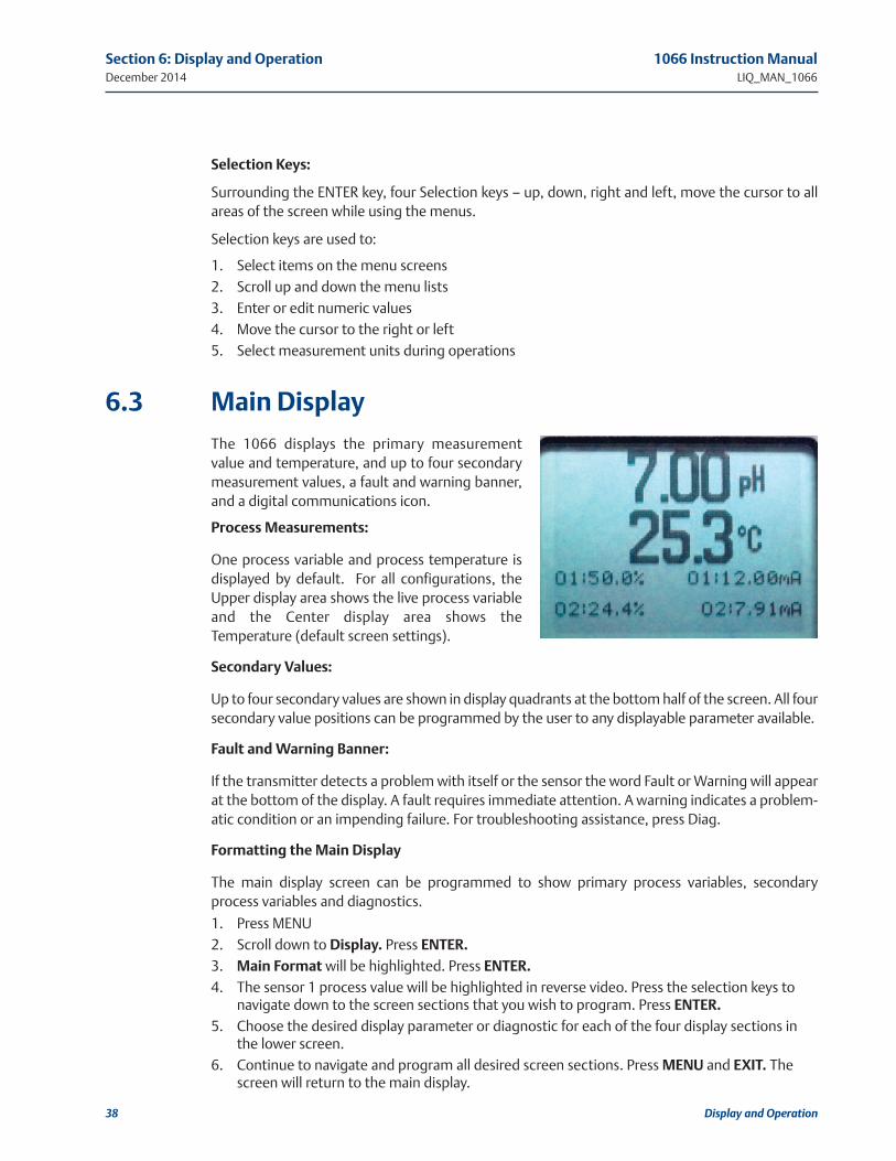
Main Display
The 1066 displays the primary measurement
value and temperature, and up to four secondary
measurement values, a fault and warning banner,
and a digital communications icon.
process Measurements:
One process variable and process temperature is
displayed by default. For all configurations, the
Upper display area shows the live process variable
and the Center display area shows the
Temperature (default screen settings).
Secondary values:
Up to four secondary values are shown in display quadrants at the bottom half of the screen. All four
secondary value positions can be programmed by the user to any displayable parameter available.
Fault and Warning Banner:
If the transmitter detects a problem with itself or the sensor the word Fault or Warning will appear
at the bottom of the display. A fault requires immediate attention. A warning indicates a problem-
atic condition or an impending failure. For troubleshooting assistance, press Diag.
Formatting the Main Display
The main display screen can be programmed to show primary process variables, secondary
process variables and diagnostics.
1. Press MENU
2. Scroll down to Display. Press EnTEr.
3. Main Format will be highlighted. Press EnTEr.
4. The sensor 1 process value will be highlighted in reverse video. Press the selection keys tonavigate down to the screen sections that you wish to program. Press EnTEr.
5. Choose the desired display parameter or diagnostic for each of the four display sections inthe lower screen.
6. Continue to navigate and program all desired screen sections. Press MEnu and ExIT. Thescreen will return to the main display.
38 Display and Operation

1066 Instruction Manual Section 6: Display and operationLIQ_MAN_1066 December 2014
Display and Operation 39
The default display shows the live process measurement in the upper display area and temperature
in the center display area. The user can elect to disable the display of temperature in the center dis-
play area using the Main Format function. See Fig. 4-1 to guide you through programming the
main display to select process parameters and diagnostics of your choice.
Menu System
The 1066 uses a scroll and select menu system.
Pressing the MENU key at any time opens the
top-level menu including Calibrate, Hold,
Program and Display functions.
To find a menu item, scroll with the up and down
keys until the item is highlighted. Continue to
scroll and select menu items until the desired
function is chosen.
To select the item, press ENTER. To return to a
previous menu level or to enable the main live
display, press the EXIT key repeatedly. To return
immediately to the main display from any menu level, simply press MENU then EXIT.
The selection keys have the following functions:
• The Up key (above ENTER) increments numerical values, moves the decimal place one place
to the right, or selects units of measurement.
• The Down key (below ENTER) decrements numerical values, moves the decimal place one
place to the left, or selects units of measurement
• The Left key (left of ENTER) moves the cursor to the left.
• The Right key (right of ENTER) moves the cursor to the right.
To access desired menu functions, use the Quick Reference. During all menu displays (except main
display format and Quick Start), the live process measurement and temperature value are dis-
played in the top two lines of the Upper display area. This conveniently allows display of the live val-
ues during important calibration and programming operations. Menu screens will time out after
two minutes and return to the main live display.
6.4

40 Display and Operation
Section 6: Display and operation 1066 Instruction ManualDecember 2014 LIQ_MAN_1066
This page left intentionally blank

1066 Instruction Manual Section 7: Transmitter programmingLIQ_MAN_1066 December 2014
7.1
7.2
7.2.1
Section 7: Programming the Transmitter – Basics
TABLE 7-1. Measurements and Measurement units
Transmitter Programming 41
Signal board Available measurements Measurements units:
pH/ORP – P pH, ORP, Redox pH, mV (ORP, Redox)
Contacting conductivity – C
Conductivity, Resistivity, TDS, Salinity, NaOH (0-12%), HCl (0-15%), Low H2SO4, High H2SO4, NaCl (0-20%), Custom Curve
μS/cm, mS/cm, S/cm% (concentration)
Toroidal conductivity –TConductivity, Resistivity, TDS, Salinity, NaOH (0-12%), HCl (0-15%), Low H2SO4, High H2SO4, NaCl (0-20%), Custom Curve
μS/cm, mS/cm, S/cm% (concentration)
Chlorine – CLFree Chlorine, Total Chlorine, Monochloramine ppm, mg/L
Oxygen – DO Oxygen (ppm), Trace Oxygen (ppb), Percent Oxygen in gas
ppm, mg/L, ppb, µg/L % Sat, Partial Pressure, % Oxygen In Gas, ppm Oxygen In Gas
Ozone – OZ Ozone ppm, mg/L, ppb, μg/L
General
Typical programming steps include the following listed procedures. Each of these programming
functions are easily and quickly accomplished using the intuitive menu system.
• Changing the measurement type, measurement units and temperature units.
• Choose temperature units and manual or automatic temperature compensation mode
• Configure and assign values to the current outputs
• Set a security code for two levels of security access
• Accessing menu functions using a security code
• Enabling and disabling Hold mode for current outputs
• Resetting all factory defaults, calibration data only, or current output settings only
Changing Startup Settings
Purpose
To change the measurement type, measurement units, or temperature units that were initially
entered in Quick Start, choose the Reset analyzer function or access the Program menus for the
sensor. The following choices for specific measurement type, measurement units are available for
each sensor measurement board.

Section 7: Transmitter programming 1066 Instruction ManualDecember 2014 LIQ_MAN_1066
Procedure
Follow the Reset Analyzer procedure (Sec 7.8) to reconfigure the transmitter to display new
measurements or measurement units. To change the specific measurement or measurement
units for each measurement type, refer to the Program menu for the appropriate measurement
(Sec. 6.0).
Choosing Temperature units andAutomatic/Manual Temperature Compensation
Purpose
Most liquid analytical measurements (except ORP and Redox)
require temperature compensation. The 1066 performs tempera-
ture compensation automatically by applying internal temperature
correction algorithms. Temperature correction can also be turned
off. If temperature correction is off, the 1066 uses the temperature
entered by the user in all temperature correction calculations.
Configuring and ranging Current outputs
Purpose
The 1066 has two analog current outputs. Ranging the outputs means assigning values to the
low (4 mA) and high (20 mA) outputs. This section provides a guide for configuring and ranging
the outputs. ALWAYS CONFIGURE THE OUTPUTS FIRST.
Definitions
1. CURRENT OUTPUTS. The transmitter provides a continuous output current (4-20 mA)
directly proportional to the process variable or temperature. The low and high current out-
puts can be set to any value.
2. ASSIGNING OUTPUTS. Assign a measurement or temperature to Output 1 or Output 2.
3. DAMPEN. Output dampening smooths out noisy readings. It also increases the responsetime of the output. Output dampening does not affect the response time of the display.
4. MODE. The current output can be made directly proportional to the displayed value (linearmode) or directly proportional to the common logarithm of the displayed value (log mode).
Procedure: Configure Outputs
Under the Program/Outputs menu, the adjacent screen will
appear to allow configuration of the outputs. Follow the menu
screens in Fig. 7-1 to configure the outputs.
7.2.2
7.3
7.3.1
7.4
7.4.1
7.4.2
7.4.3
1.234µS/cm 25.0ºC
Temperature
Units: °C
Temp Comp: Auto
Manual: +25.0°C
1.234µS/cm 25.0ºC
OutputM Configure
Assign: Meas
Scale: Linear
Dampening: 0sec
Fault Mode: Fixed
Fault Value: 21.00mA
42 Transmitter Programming

Transmitter Programming 43
1066 Instruction Manual Section 7: Transmitter programmingLIQ_MAN_1066 December 2014
7.4.4
7.5
7.5.1
7.5.2
Procedure: Ranging the Current Outputs
The adjacent screen will appear under Program/Output/Range.
Enter a value for 4mA and 20mA for each output. Follow the menu
screens in Fig. 7-1 to assign values to the outputs.
Setting a Security Code
Purpose
The security codes prevent accidental or unwanted changes to program settings, displays, and
calibration. The 1066 has two levels of security code to control access and use of the instrument
to different types of users. The two levels of security are: • All: This is the Supervisory security level. It allows access to all menu functions, including
Programming, Calibration, Hold and Display.
• Calibration/hold: This is the operator or technician level menu. It allows access to only cali-bration and Hold of the current outputs.
Procedure
1. Press MENU. The main menu screen appears. Choose program.
2. Scroll down to Security. Select Security.
3. The security entry screen appears. Enter a three digit security code for each of the desiredsecurity levels. The security code takes effect two minutes after the last key stroke. Record thesecurity code(s) for future access and communication to operators or technicians as needed.
4. The display returns to the security menu screen. Press EXIT to return to the previous screen.To return to the main display, press MENU followed by EXIT.
Fig. 7-2 displays the security code screens.
1.234µS/cm 25.0ºC
Output Range
O1 SN 4mA: 0.000µS/cm
O1 SN 20mA: 20.00µS/cm
O2 SN 4mA: 0°C
O2 SN 20mA: 100°C
1.234µS/cm 25.0ºC
Program
OutputsMeasurementTemperature
SecurityDiagnostic SetupReset Analyzer
Outputs
Pro
gram
Range
Configure
Simulate
1.234µS/cm 25.0ºC
Output ConfigureOutput1 Output2
1.234µS/cm 25.0ºC
Outputs
Range ConfigureSimulate
1.234µS/cm 25.0ºC
Output RangeO1 SN 4mA: 0.000O1 SN 20mA: 20.00O2 SN 4mA: 0ºCS2 20mA: 100ºC
1.234µS/cm 25.0ºC
SimulateOutput 1Output 2
1.234µS/cm 25.0ºC
Output RangeOM 4mA: 1.000 OM 20mA: 1.000% OM 4mA: 1.000%OM 20mA: 7.0 pH
1.234µS/cm 25.0ºC
OutputN Hold At12.00mA
1.234µS/cm 25.0ºC
OutputM ConfigureAssign: S1 MeasRange: 4-20mAScale: LinearDampening: 0sec
MA
IN M
EN
U 1.234µS/cm 25.0ºC
OutputM AssignS1 MeasurementS1 Temperature
1.234µS/cm 25.0ºC
OutputM Range4-20mA0-20mA
1.234µS/cm 25.0ºC
ScaleLinearLog
FIGurE 7-1. Configuring andranging the Current outputs

Section 7: Transmitter programming 1066 Instruction ManualDecember 2014 LIQ_MAN_1066
44 Transmitter Programming
Security Access
How the Security Code Works
When entering the correct access code for the Calibration/Hold security level, the Calibration and
Hold menus are accessible. This allows operators or technicians to perform routine maintenance.
This security level does not allow access to the Program or Display menus. When entering the cor-
rect access code for All security level, the user has access to all menu functions, including
Programming, Calibration, Hold and Display.
Procedure
1. If a security code has been programmed, selecting the Calibrate, Hold, Program or Display topmenu items causes the security access screen to appear
2. Enter the three-digit security code for the appropriate security level.
3. If the entry is correct, the appropriate menu screen appears. If theentry is incorrect, the Invalid Code screen appears. The EnterSecurity Code screen reappears after 2 seconds.
using hold
Purpose
The transmitter output is always proportional to measured value. To prevent improper operation
of systems or pumps that are controlled directly by the current output, place the analyzer in hold
before removing the sensor for calibration and maintenance. Be sure to remove the transmitter
from hold once calibration is complete. During hold, both outputs remain at the last value. Once
in hold, all current outputs remain on Hold indefinitely.
7.6
7.6.1
7.6.2
7.7
7.7.1
FIGurE 7-2. Setting a Security Code
1.234µS/cm 25.0ºC
Security
Calibration/Hold: 000
All: 000
MA
IN M
EN
U
1.234µS/cm 25.0ºC
Program
Outputs
Measurement
Temperature
Diagnostic SetupReset Analyzer
Security
Pro
gra
m
1.234µS/cm 25.0ºC
Security Code
000

1066 Instruction Manual Section 7: Transmitter programmingLIQ_MAN_1066 December 2014
Transmitter Programming 45
7.7.2
7.8
7.8.1
7.8.2
Using the Hold Function
To hold the outputs,
1. Press MENU. The main menu screen appears. Choose hold.
2. The hold outputs? screen appears. Choose Yes to place the analyzer in hold. Choose no totake the analyzer out of hold.
3. The Hold screen will then appear and hold will remain on indefinitely until hold is disabled.See Figure 7-3.
resetting Factory Default Settings
Purpose
This section describes how to restore factory calibration and default values. The process also
clears all fault messages and returns the display to the first Quick Start screen. The 1066 offers
three options for resetting factory defaults.
1. Reset all settings to factory defaults
2. Reset sensor calibration data only
3. Reset analog output settings only
Procedure
To reset to factory defaults, reset calibration data only or reset analog outputs only, follow the
Reset Analyzer flow diagram.
FIGurE 7-3. using hold
MA
IN M
EN
U
Ho
ld
1.234µS/cm 25.0ºC
Hold outputs?
No
Yes
1.234µS/cm 25.0ºC
Hold
Hold: No

Section 7: Transmitter programming 1066 Instruction ManualDecember 2014 LIQ_MAN_1066
46 Transmitter Programming
FIGurE 7-4. resetting Factory Default Settings

1066 Instruction Manual Section 8: programming MeasurementsLIQ_MAN_1066 December 2014
Programming Measurements 47
Introduction
The 1066 automatically recognizes the measurement input upon first power-up and each time
the transmitter is powered. Completion of Quick Start screens upon first power up enable meas-
urements, but additional steps may be required to program the transmitter for the desired meas-
urement application. This section covers the following programming and configuration
functions:
1. Selecting measurement type or sensor type (all sections)
2. Identifying the preamp location (pH-see Sec. 8.2)
3. Enabling manual temperature correction and entering a reference temperature (all sections)
4. Enabling sample temperature correction and entering temperature correction slope (selected
sections)
5. Defining measurement display resolution (pH and amperometric)
6. Defining measurement display units (all sections)
7. Adjusting the input filter to control display and output reading variability or noise (all sections)
8. Selecting a measurement range (conductivity – see Secs 8.4, 8.5)
9. Entering a cell constant for a contacting or toroidal sensor (see Secs 8.4, 8.5)
10. Creating an application-specific concentration curve (conductivity-see Secs 8.4, 8.5)
11. Enabling automatic pH correction for free chlorine measurement (Sec. 8.6.1)
To fully configure the transmitter, you may use the following:
1. Reset Transmitter function to reset factory defaults and configure to the desired measure-
ment. Follow the Reset Transmitter menu to reconfigure the transmitter to display new meas-
urements or measurement units.
2. Program menus to adjust any of the programmable configuration items. Use the following
configuration and programming guidelines for the applicable measurement.
8.1
Section 8: Programming Measurements

Section 8: programming Measurements 1066 Instruction ManualDecember 2014 LIQ_MAN_1066
48 Programming Measurements
ph Measurement programming
Description
The section describes how to configure the 1066 transmitter for pH measurements. The follow-
ing programming and configuration functions are covered.
1. Measurement type: pH Select pH, ORP, Redox.
2. Preamp location: Transmitter Identify preamp location (automatic detection for SMART pH
sensors)
3. Filter: 4 sec Override the default input filter, enter 0-999 seconds
4. Reference Z: Low Select low or high reference impedance
5. Resolution: 0.01pH Select 0.01pH or 0.1pH for pH display resolution
To configure pH:
1. Press MEnu
2. Scroll down to program. Press ENTER.
3. Scroll down to Measurement. Press ENTER.
The adjacent screen format will appear (factory defaults are shown).
To program any function, scroll to the desired item and press ENTER.
The following sub-sections provide you with the initial display screen that appears for each con-
figuration function. Use the flow diagram for pH programming and the 1066 live screen prompts
for each function to complete configuration and programming.
Measurement
The display screen for selecting the measurement is shown. The default
value is displayed in bold type. Refer to the pH/ORP Programming flow
diagram to complete this function.
Preamp
The display screen for identifying the Preamp location is shown. The
default value is displayed in bold type. Refer to the pH/ORP
Programming flow diagram to complete this function.
note: Sensor/JBox must be selected to support SMART pH sensors from
Rosemount Analytical.
8.2
8.2.1
8.2.2
8.2.3
1.234µS/cm 25.0ºC
SN Configure
Measure: pH
Preamp: Analyzer
Sol’n Temp Corr: Off
Resolution: 0.01pH
Filter: 4 sec
Reference Z: Low
1.234µS/cm 25.0ºC
SN Measurement
pH
ORP
Redox
1.234µS/cm 25.0ºC
SN Preamp
Analyzer
Sensor/JBox
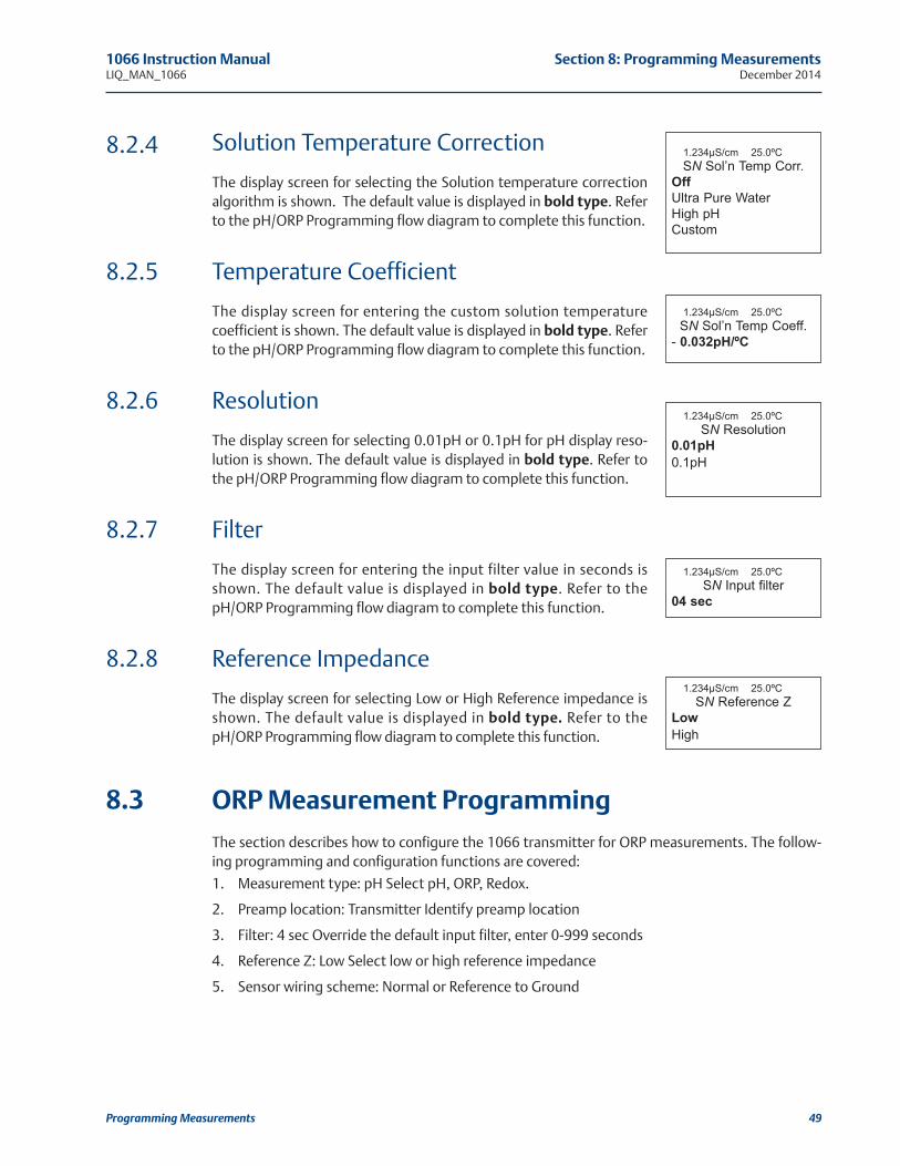
1066 Instruction Manual Section 8: programming MeasurementsLIQ_MAN_1066 December 2014
Programming Measurements 49
Solution Temperature Correction
The display screen for selecting the Solution temperature correction
algorithm is shown. The default value is displayed in bold type. Refer
to the pH/ORP Programming flow diagram to complete this function.
Temperature Coefficient
The display screen for entering the custom solution temperature
coefficient is shown. The default value is displayed in bold type. Refer
to the pH/ORP Programming flow diagram to complete this function.
Resolution
The display screen for selecting 0.01pH or 0.1pH for pH display reso-
lution is shown. The default value is displayed in bold type. Refer to
the pH/ORP Programming flow diagram to complete this function.
Filter
The display screen for entering the input filter value in seconds is
shown. The default value is displayed in bold type. Refer to the
pH/ORP Programming flow diagram to complete this function.
Reference Impedance
The display screen for selecting Low or High Reference impedance is
shown. The default value is displayed in bold type. Refer to the
pH/ORP Programming flow diagram to complete this function.
orp Measurement programming
The section describes how to configure the 1066 transmitter for ORP measurements. The follow-
ing programming and configuration functions are covered:
1. Measurement type: pH Select pH, ORP, Redox.
2. Preamp location: Transmitter Identify preamp location
3. Filter: 4 sec Override the default input filter, enter 0-999 seconds
4. Reference Z: Low Select low or high reference impedance
5. Sensor wiring scheme: Normal or Reference to Ground
8.2.4
8.2.5
8.2.6
8.2.7
8.2.8
8.3
1.234µS/cm 25.0ºC
SN Sol’n Temp Corr.
Off
Ultra Pure Water
High pH
Custom
1.234µS/cm 25.0ºC
SN Resolution
0.01pH
0.1pH
1.234µS/cm 25.0ºC
SN Sol’n Temp Coeff.
- 0.032pH/ºC
1.234µS/cm 25.0ºC
SN Reference Z
Low
High
1.234µS/cm 25.0ºC
SN Input filter
04 sec

Section 8: programming Measurements 1066 Instruction ManualDecember 2014 LIQ_MAN_1066
50 Programming Measurements
To configure ORP:
1. Press MEnu
2. Scroll down to program. Press ENTER.
3. Scroll down to Measurement. Press ENTER.
The adjacent screen format will appear (factory defaults are shown).
To program any displayed function, scroll to the desired item and press ENTER.
The following sub-sections provide you with the initial display screen that appears for each con-
figuration function. Use the flow diagram for orp programming at the end of Sec. 6 and the
1066 live screen prompts for each function to complete configuration and programming.
Measurement
The display screen for selecting the measurement is shown. The
default value is displayed in bold type. Refer to the pH/ORP
Programming flow diagram to complete this function.
Preamp
The display screen for identifying the Preamp location is shown. The
default value is displayed in bold type. Refer to the pH/ORP
Programming flow diagram to complete this function.
Filter
The display screen for entering the input filter value in seconds is
shown. The default value is displayed in bold type. Refer to the
pH/ORP Programming flow diagram to complete this function.
Reference Impedance
The display screen for Selecting Low or high Reference impedance is
shown. The default value is displayed in bold type. Refer to the
pH/ORP Programming flow diagram to complete this function.
8.3.1
8.3.2
8.3.3
8.3.4
1.234µS/cm 25.0ºC
SN Preamp
Analyzer
Sensor/JBox
1.234µS/cm 25.0ºC
SN Input filter
04 sec
1.234µS/cm 25.0ºC
SN Reference Z
Low
High
1.234µS/cm 25.0ºC
SN Configure
Measure: pH
Preamp: Analyzer
Flter: 4 sec
Reference Z: Low
1.234µS/cm 25.0ºC
SN Measurement
pH
ORP
Redox

1066 Instruction Manual Section 8: programming MeasurementsLIQ_MAN_1066 December 2014
Programming Measurements 51
Contacting Conductivity Measurementprogramming
Description
The section describes how to configure the 1066 transmitter for conductivity measurements
using contacting conductivity sensors. The following programming and configuration functions
are covered.
1. Measure: Conductivity Select Conductivity, Resistivity, TDS. Salinity or % conc
2. Type: 2-Electrode Select 2-Electrode or 4-Electrode type sensors
3. Cell K: 1.00000/cm Enter the cell Constant for the sensor
4. Measurement units
5. Filter: 2 sec Override the default input filter, enter 0-999 seconds
6. Range: Auto Select measurement Auto-range or specific range
7. Temp Comp: Slope Select Temp Comp: Slope, Neutral Salt, Cation or Raw
8. Slope: 2.00%/°C Enter the linear temperature coefficient
9. Ref Temp: 25.0°C Enter the Reference temp
10. Cal Factor: default=0.95000/cm Enter the Cal Factor for 4-Electrode sensors from the sensor tag
To configure the contacting conductivity:
1. Press MENU
2. Scroll down to Program. Press ENTER.
3. Scroll down to Measurement. Press ENTER.
The adjacent screen format will appear (factory defaults are shown). To
program any displayed function, scroll to the desired item and press
ENTER.
The following sub-sections provide you with the initial display screen that appears for each con-
figuration function. Use the flow diagram for contacting conductivity programming at the end of
Sec. 8 and the 1066 live screen prompts for each function to complete configuration and pro-
gramming.
Sensor Type
The display screen for selecting 2-Electrode or 4-Electrode type sensors is
shown. The default value is displayed in bold type. Refer to the contact-
ing conductivity Programming flow diagram to complete this function.
8.4
8.4.1
8.4.2
1.234µS/cm 25.0ºC
SN Configure
Type: 2-Electrode
Measure: Cond
Range: Auto
Cell K: 1.00000/cm
RTD Offset: 0.00ºC
RTD Slope: 0
Temp Comp: Slope
Slope: 2.00%/°C
Ref Temp: 25.0°C
Filter: 2 sec
Custom Setup
1.234µS/cm 25.0ºC
SN Type
2-Electrode
4-Electrode
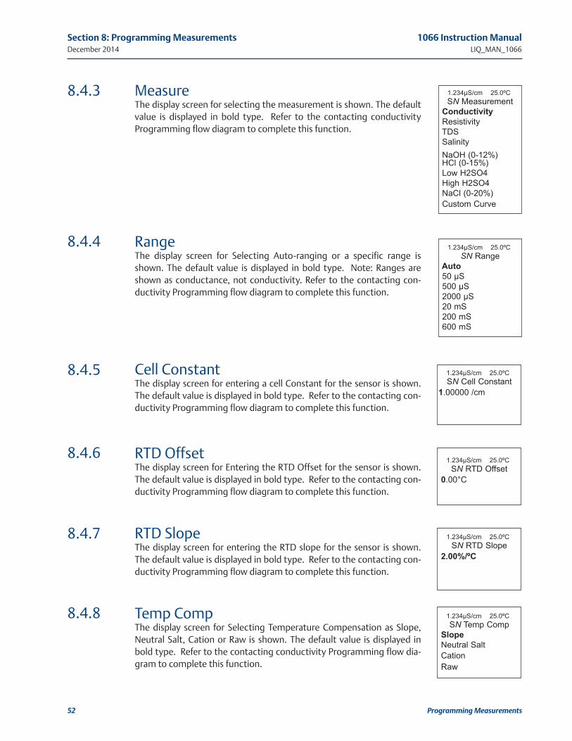
Section 8: programming Measurements 1066 Instruction ManualDecember 2014 LIQ_MAN_1066
52 Programming Measurements
MeasureThe display screen for selecting the measurement is shown. The default
value is displayed in bold type. Refer to the contacting conductivity
Programming flow diagram to complete this function.
RangeThe display screen for Selecting Auto-ranging or a specific range is
shown. The default value is displayed in bold type. Note: Ranges are
shown as conductance, not conductivity. Refer to the contacting con-
ductivity Programming flow diagram to complete this function.
Cell ConstantThe display screen for entering a cell Constant for the sensor is shown.
The default value is displayed in bold type. Refer to the contacting con-
ductivity Programming flow diagram to complete this function.
RTD OffsetThe display screen for Entering the RTD Offset for the sensor is shown.
The default value is displayed in bold type. Refer to the contacting con-
ductivity Programming flow diagram to complete this function.
RTD SlopeThe display screen for entering the RTD slope for the sensor is shown.
The default value is displayed in bold type. Refer to the contacting con-
ductivity Programming flow diagram to complete this function.
Temp CompThe display screen for Selecting Temperature Compensation as Slope,
Neutral Salt, Cation or Raw is shown. The default value is displayed in
bold type. Refer to the contacting conductivity Programming flow dia-
gram to complete this function.
8.4.3
8.4.4
8.4.5
8.4.6
8.4.7
8.4.8
1.234µS/cm 25.0ºC
SN Measurement
Conductivity
Resistivity
TDS
Salinity
NaOH (0-12%)HCl (0-15%)
Low H2SO4
High H2SO4
NaCl (0-20%)
Custom Curve
1.234µS/cm 25.0ºC
SN Range
Auto
50 µS
500 µS
2000 µS
20 mS
200 mS
600 mS
1.234µS/cm 25.0ºC
SN Cell Constant
1.00000 /cm
1.234µS/cm 25.0ºC
SN RTD Offset
0.00°C
1.234µS/cm 25.0ºC
SN RTD Slope
2.00%/ºC
1.234µS/cm 25.0ºC
SN Temp Comp
Slope
Neutral Salt
Cation
Raw

1066 Instruction Manual Section 8: programming MeasurementsLIQ_MAN_1066 December 2014
Programming Measurements 53
SlopeThe display screen for Entering the conductivity/temp Slope is shown.
The default value is displayed in bold type. Refer to the contacting con-
ductivity Programming flow diagram to complete this function.
Reference TempThe display screen for manually entering the Reference temperature is
shown. The default value is displayed in bold type. Refer to the contact-
ing conductivity Programming flow diagram to complete this function.
FilterThe display screen for entering the input filter value in seconds is shown.
The default value is displayed in bold type. Refer to the contacting con-
ductivity Programming flow diagram to complete this function.
Custom SetupThe display screens for creating a custom curve for converting conduc-
tivity to concentration is shown. Refer to the contacting conductivity
Programming flow diagram to complete this function.
When the custom curve data entry is complete, press ENTER. The dis-
play will confirm the determination of a custom curve fit to the entered
data by displaying this screen:
If the custom curve fit is not completed or is unsuccessful, the display will
read as follows and the screen will return to the beginning custom curve
screen.
Cal Factor Upon initial installation and power up, if 4-electrode was selected for the
sensor type in the Quick Start menus, the user enters a Cell Constant and
a “Cal Factor” using the instrument keypad. The cell constant is needed
to convert measured conductance to conductivity as displayed on the
transmitter screen. The “Cal Factor” entry is needed increase the accura-
cy of the live conductivity readings, especially at low conductivity read-
ings below 20uS/cm. Both the Cell Constant and the “Cal Factor” are
printed on the tag attached to the 4-electrode sensor/cable.
8.4.9
8.4.10
8.4.11
8.4.12
8.4.13
1.234µS/cm 25.0ºC
SN Slope
2.00 %/ºC
1.234µS/cm 25.0ºC
SN Ref Temp
(25.0ºC normal)
+25.0ºC
1.234µS/cm 25.0ºC
SN Input filter
02 sec
1.234µS/cm 25.0ºC
SN Custom Curve
Configure
Enter Data Points
Calculate Curve
1.234µS/cm 25.0ºC
SN Cal Factor
0.95000/cm
1.234µS/cm 25.0ºC
SN Calculate Curve
Custom curve
fit completed.
In Process Cal
recommended.
1.234µS/cm 25.0ºC
SN Calculate Curve
Failure

Section 8: programming Measurements 1066 Instruction ManualDecember 2014 LIQ_MAN_1066
54 Programming Measurements
Toroidal Conductivity Measurement programming
Description
The section describes how to configure the 1066 transmitter for conductivity measurements
using inductive/toroidal sensors. The following programming and configuration functions are cov-
ered:
1. Measure: Conductivity Select Conductivity, Resistivity, TDS. Salinity or % conc
2. Sensor Model: 228 Select sensor type
3. Measurement units
4. Range selection
5. Cell K: 3.00000/cm Enter the cell Constant for the sensors
6. Temp Comp: Slope Select Temp Comp: Slope, Neutral Salt, Cation or Raw
7. Slope: 2.00%/°C Enter the linear temperature coefficient
8. Ref Temp: 25.0°C Enter the Reference temp
9. Filter: 2 sec Override the default input filter, enter 0-999 seconds
To configure toroidal conductivity:
1. Press MENU
2. Scroll down to Program. Press ENTER.
3. Scroll down to Measurement. Press ENTER.
The adjacent screen format will appear (factory defaults are shown). To
program any displayed function, scroll to the desired item and press
ENTER.
The following sub-sections provide you with the initial display screen that appears for each con-
figuration function. Use the flow diagram for toroidal conductivity programming at the end of
Sec. 8 and the 1066 live screen prompts for each function to complete configuration and pro-
gramming.
Sensor Type
The display screen for selecting the sensor model is shown. The default
value is displayed in bold type. Refer to the toroidal conductivity
Programming flow diagram to complete this function.
8.5
8.5.1
8.5.2
1.234µS/cm 25.0ºC
SN Configure
Model: 228
Measure: Cond
Range: Auto
Cell K: 3.00000/cm
RTD Offset: 0.00ºC
RTD Slope: 0
Temp Comp: Slope
Slope: 2.00%/°C
Ref Temp: 25.0°C
Filter: 2 sec
Custom Setup
1.234µS/cm 25.0ºC
SN Model
228
225
226
247
Other

1066 Instruction Manual Section 8: programming MeasurementsLIQ_MAN_1066 December 2014
Programming Measurements 55
MeasureThe display screen for selecting the measurement is shown. The default
value is displayed in bold type. Refer to the toroidal conductivity
Programming flow diagram to complete this function.
RangeThe display screen for Selecting Auto-ranging or a specific range is
shown. The default value is displayed in bold type. Note: Ranges are
shown as conductance, not conductivity. Refer to the toroidal conduc-
tivity Programming flow diagram to complete this function.
noTE: when manually changing ranges, a zero calibration and recal-
ibration in a solution of known conductivity must be performed
with the toroidal sensor wired to the instrument. refer to sec. 9.5.2
zeroing the Instrument and sec. 9.5.3 Calibrating the Sensor in a
Conductivity Standard.
Cell ConstantThe display screen for entering a cell Constant for the sensor is shown.
The default value is displayed in bold type. Refer to the toroidal conduc-
tivity Programming flow diagram to complete this function.
noTE: When manually changing ranges, the Cell Constant may
change through the calibration process.
Temp CompThe display screen for Selecting Temperature Compensation as Slope,
Neutral Salt, or Raw is shown. The default value is displayed in bold type.
Refer to the toroidal conductivity Programming flow diagram to com-
plete this function.
8.5.3
8.5.4
8.5.5
8.5.6
1.234µS/cm 25.0ºC
Cell Constant
2.7000 /cm
1.234µS/cm 25.0ºC
Measurement
Conductivity
Resistivity
TDS
Salinity
NaOH (0-12%)
HCl (0-15%)
Low H2SO4
High H2SO4
NaCl (0-20%)
Custom Curve
1.234µS/cm 25.0ºC
SN Range
Auto
50-600 µS
0.5-100 mS
90-1500 mS
1.234µS/cm 25.0ºC
Temp Comp
Slope
Raw

Section 8: programming Measurements 1066 Instruction ManualDecember 2014 LIQ_MAN_1066
56 Programming Measurements
SlopeThe display screen for Entering the conductivity/temp Slope is shown.
The default value is displayed in bold type. Refer to the toroidal conduc-
tivity Programming flow diagram to complete this function.
Ref TempThe display screen for manually Entering the Reference temperature is
shown. The default value is displayed in bold type. Refer to the toroidal
conductivity Programming flow diagram to complete this function.
FilterThe display screen for entering the input filter value in seconds is shown.
The default value is displayed in bold type. Refer to the toroidal conduc-
tivity Programming flow diagram to complete this function.
using the highest range (90mS to 1500mS) in very low conductivity
processes below 100µS (conductance) might generate a high noise
value relative to the actual process value. In these cases, it is recom-
mended to increase the input filter setting above the default value
of 2 sec. to suppress the effect of noise.
Custom SetupThe display screens for creating custom curves for converting conductiv-
ity to concentration is shown. Refer to the toroidal conductivity
Programming flow diagram to complete this function.
When the custom curve data entry is complete, press ENTER. The dis-
play will confirm the determination of a custom curve fit to the entered
data by displaying this screen:
If the custom curve fit is not completed or is unsuccessful, the display will
read as follows and the screen will return to the beginning custom curve
screen.
8.5.7
8.5.8
8.5.9
8.5.10
1.234µS/cm 25.0ºC
SN Slope
2.00%/ºC
1.234µS/cm 25.0ºC
SN Ref Temp
(25.0ºC normal)
+25.0ºC
1.234µS/cm 25.0ºC
SN Input filter
02 sec
1.234µS/cm 25.0ºC
SN Custom Curve
Configure
Enter Data Points
Calculate Curve
1.234µS/cm 25.0ºC
SN Calculate Curve
Custom curve
fit completed.
In Process Cal
recommended.
1.234µS/cm 25.0ºC
SN Calculate Curve
Failure

1066 Instruction Manual Section 8: programming MeasurementsLIQ_MAN_1066 December 2014
Programming Measurements 57
Chlorine Measurement programming
The 1066 can measure any of three variants of Chlorine:
• Free Chlorine
• Total Chlorine
• Monochloramine
The section describes how to configure the 1066 transmitter for Chlorine measurements.
Free Chlorine Measurement ProgrammingThis Chlorine sub-section describes how to configure the 1066 transmitter for Free Chlorine meas-
urement using amperometric chlorine sensors. Automatic temperature compensation is available
using Auto or Manual pH correction. For maximum accuracy, use automatic temperature com-
pensation.
The following programming and configuration functions are covered:
1. Measure: Free Chlorine Select Free Chlorine, Total Cl, Monochloramine
2. Units: ppm Select units ppm or mg/L
3 Resolution: 0.001 Select display resolution 0.01 or 0.001
4. Free Cl Correct: Live Select Live/Continuous pH correction or Manual
5. Manual pH: 7.00 pH For Manual pH correction, enter the pH value
6. Filter: 5sec Override the default input filter, enter 0-999 seconds
To configure chlorine for free chlorine:
1. Press MENU
2. Scroll down to Program. Press ENTER.
3. Scroll down to Measurement. Press ENTER.
The adjacent screen format will appear (factory defaults are shown). To
program any displayed function, scroll to the desired item and press
ENTER.
The following sub-sections provide you with the initial display screen that appears for each con-
figuration function. Use the flow diagram for chlorine programming at the end of Sec. 8 and the
1066 live screen prompts for each function to complete configuration and programming.
8.6
8.6.1
1.234µS/cm 25.0ºC
SN Configure
Measure: Free Chlorine
Units: ppm
Filter: 5sec
Free Cl Correct: Live
Manual pH: 7.00 pH
Resolution: 0.001

Section 8: programming Measurements 1066 Instruction ManualDecember 2014 LIQ_MAN_1066
58 Programming Measurements
MeasureThe display screen for selecting the measurement is shown. The default
value is displayed in bold type. Refer to the Chlorine Programming flow
diagram to complete this function.
Units The display screen for selecting units as ppm or mg/L is shown. The
default value is displayed in bold type. Refer to the Chlorine
Programming flow diagram to complete this function.
Filter The display screen for entering the input filter value in seconds is shown.
The default value is displayed in bold type. Refer to the Chlorine
Programming flow diagram to complete this function.
Free Chlorine pH CorrectionThe display screen for Selecting Live/Continuous pH correction or
Manual pH correction is shown. The default value is displayed in bold
type. Refer to the Chlorine Programming flow diagram to complete this
function.
Manual pH CorrectionThe display screen for manually entering the pH value of the measured
process liquid is shown. The default value is displayed in bold type. Refer
to the Chlorine Programming flow diagram to complete this function.
ResolutionThe display screen for selecting display resolution as 0.001 or 0.01 is
shown. The default value is displayed in bold type. Refer to the Chlorine
Programming flow diagram to complete this function.
8.6.1.1
8.6.1.2
8.6.1.3
8.6.1.4
8.6.1.5
8.6.1.6
1.234µS/cm 25.0ºC
SN Measurement
Free Chlorine
Total Chlorine
Monochloramine
1.234µS/cm 25.0ºC
SN Units
ppm
mg/L
1.234µS/cm 25.0ºC
SN Input filter
05 sec
1.234µS/cm 25.0ºC
SN Manual pH
07.00 pH
1.234µS/cm 25.0ºC
SN Resolution -
0.001
0.01
1.234µS/cm 25.0ºC
SN Free Cl
pH Correction
Live/Continuous
Manual

1066 Instruction Manual Section 8: programming MeasurementsLIQ_MAN_1066 December 2014
Programming Measurements 59
Total Chlorine Measurement Programming
Description This Chlorine sub-section describes how to configure the 1066 transmitter for Total Chlorine
measurement using amperometric chlorine sensors. The following programming and configura-
tion functions are covered:
1. Measure: Free Chlorine Select Free Chlorine, pH Ind. Free Cl. Total Cl, Monochloramine
2. Units: ppm Select units ppm or mg/L
3. Resolution: 0.001 Select display resolution 0.01 or 0.001
4. Filter: 5sec Override the default input filter, enter 0-999 seconds
To configure chlorine measurement for total chlorine:
1. Press MENU
2. Scroll down to Program. Press ENTER.
3. Scroll down to Measurement. Press ENTER.
The adjacent screen format will appear (factory defaults are shown). To program any displayed
function, scroll to the desired item and press ENTER.
The following sub-sections provide you with the initial display screen that appears for each con-
figuration function. Use the flow diagram for chlorine programming at the end of Sec. 6 and the
1066 live screen prompts for each function to complete configuration and programming.
MeasureThe display screen for selecting the measurement is shown. The default
value is displayed in bold type. Refer to the chlorine Programming flow
diagram to complete this function.
Units The display screen for selecting units as ppm or mg/L is shown. The
default value is displayed in bold type. Refer to the Chlorine
Programming flow diagram to complete this function
FilterThe display screen for entering the input filter value in seconds is shown.
The default value is displayed in bold type. Refer to the Chlorine
Programming flow diagram to complete this function.
8.6.2
8.6.2.1
8.6.2.2
8.6.2.3
8.6.2.4
1.234µS/cm 25.0ºC
SN Measurement
Free Chlorine
Total Chlorine
Monochloramine
1.234µS/cm 25.0ºC
SN Units
ppm
mg/L
1.234µS/cm 25.0ºC
SN Configure
Measure: Free Chlorine
Units: ppm
Filter: 5sec
Resolution: 0.001
1.234µS/cm 25.0ºC
SN Input filter
05 sec

Section 8: programming Measurements 1066 Instruction ManualDecember 2014 LIQ_MAN_1066
60 Programming Measurements
ResolutionThe display screen for selecting display resolution as 0.001 or 0.01 is
shown. The default value is displayed in bold type. Refer to the Chlorine
Programming flow diagram to complete this function.
Monochloramine Measurement Programming
This Chlorine sub-section describes how to configure the 1066 transmitter for Monochloramine
measurement using amperometric chlorine sensors. The following programming and configura-
tion functions are covered:
1. Measure: Free Chlorine Select Free Chlorine, pH Ind. Free Cl. Total Cl, Monochloramine
2. Units: ppm Select units ppm or mg/L
3. Resolution: 0.001 Select display resolution 0.01 or 0.001
4. Filter: 5sec Override the default input filter, enter 0-999 seconds
To configure chlorine for monochloramine:
1. Press MENU
2. Scroll down to Program. Press ENTER.
3. Scroll down to Measurement. Press ENTER.
The following screen format will appear (factory defaults are shown). To program any displayed
function, scroll to the desired item and press ENTER.
The following sub-sections provide you with the initial display screen that appears for each con-
figuration function. Use the flow diagram for chlorine programming at the end of Sec. 8 and the
1066 live screen prompts for each function to complete configuration and programming.
Measure: MonochloramineThe display screen for selecting the measurement is shown. The
default value is displayed in bold type. Refer to the Chlorine
Programming flow diagram to complete this function.
UnitsThe display screen for selecting units as ppm or mg/L is shown. The
default value is displayed in bold type. Refer to the Chlorine
Programming flow diagram to complete this function.
8.6.2.5
8.6.3
8.6.3.1
8.6.3.2
1.234µS/cm 25.0ºC
SN Resolution
0.001
0.01
1.234µS/cm 25.0ºC
SN Configure
Measure: Free Chlorine
Units: ppm
Filter: 5sec
Resolution: 0.001
1.234µS/cm 25.0ºC
SN Measurement
Free Chlorine
Total Chlorine
Monochloramine
1.234µS/cm 25.0ºC
SN Units
ppm
mg/L

1066 Instruction Manual Section 8: programming MeasurementsLIQ_MAN_1066 December 2014
Programming Measurements 61
FilterThe display screen for entering the input filter value in seconds is
shown. The default value is displayed in bold type. Refer to the
Chlorine Programming flow diagram to complete this function.
ResolutionThe display screen for selecting display resolution as 0.001 or 0.01 is
shown. The default value is displayed in bold type. Refer to the
Chlorine Programming flow diagram to complete this function.
oxygen Measurement programming
This section describes how to configure the 1066 transmitter for dissolved and gaseous oxygen
measurement using amperometric oxygen sensors. The following programming and configura-
tion functions are covered:
1. Sensor type: Select Water/Waste, Trace. BioRx, BioRx-Other, Brew, %O2 In Gas
2. Measure type: Select Concentration, % Saturation, Partial Pressure, Oxygen in Gas
3. Units: ppm Select ppm, mg/L, ppb, g/L, % Sat, %O2-Gas, ppm Oxygen-Gas
4. Pressure Units: bar Select pressure units: mm Hg, in Hg, Atm, kPa, mbar, bar
5. Salinity: 00.0‰ Enter Salinity as ‰
6. Filter: 5sec Override the default input filter, enter 0-999 seconds
7. Partial Press: mmHg Select mm Hg, in Hg. atm, kPa, mbar or bar for Partial pressure
To configure Oxygen:
1. Press MENU
2. Scroll down to Program. Press ENTER.
3. Scroll down to Measurement. Press ENTER.
The adjacent screen format will appear (factory defaults are shown). To
program any displayed function, scroll to the desired item and press
ENTER.
The following sub-sections show the initial display screen that appears for each configuration func-
tion. Use the flow diagram for oxygen programming at the end of Sec. 6 and the 1066 live screen
prompts for each function to complete configuration and programming.
8.6.3.3
8.6.3.4
8.7
1.234µS/cm 25.0ºC
SN Input filter
05 sec
1.234µS/cm 25.0ºC
SN Resolution
0.001
0.01
1.234µS/cm 25.0ºC
SN Configure
Type: Water/Waste
Units: ppm
Partial Press: mmHg
Salinity: 00.0‰
Filter: 5sec
Pressure Units: bar
Use Press: At Air Cal
Custom Setup

Section 8: programming Measurements 1066 Instruction ManualDecember 2014 LIQ_MAN_1066
62 Programming Measurements
Oxygen Measurement applicationThe display screen for programming the measurement is shown. The
default value is displayed in bold type. Refer to the Oxygen
Programming flow diagram to complete this function.
UnitsThe display screen for selecting units as ppm , mg/L, ppb, μg/L, %
Saturation, %Oxygen in Gas, or ppm Oxygen in Gas is shown. The
default value is displayed in bold type. Refer to the Oxygen
Programming flow diagram to complete this function.
Partial PressThe display screen for selecting pressure units for Partial pressure is shown.
This selection is needed if the specified measurement is Partial pressure.
The default value is displayed in bold type. Refer to the Oxygen
Programming flow diagram to complete this function.
Salinity The display screen for Entering the Salinity (as parts per thousand) of the
process liquid to be measured is shown. The default value is displayed in
bold type. Refer to the Oxygen Programming flow diagram to complete
this function.
Enter Salinity as ‰
FilterThe display screen for entering the input filter value in seconds is shown.
The default value is displayed in bold type. Refer to the Oxygen
Programming flow diagram to complete this function.
Pressure UnitsThe display screen for selecting pressure units for atmospheric pressure is
shown. This selection is needed for the display of atmospheric pressure.
The default value is displayed in bold type. The user must enter a known
value for local atmospheric pressure. Refer to the Oxygen Programming
flow diagram to complete this function.
8.7.1
8.7.2
8.7.3
8.7.4
8.7.5
8.7.6
1.234µS/cm 25.0ºC
SN Type
Water/Waste
Trace Oxygen
BioRx-Rosemount
BioRx-Other
BrewingOxygen In Gas
1.234µS/cm 25.0ºC
SN Units
ppm
mg/L
ppb
µg/L
% Saturation
Partial Pressure
% Oxygen In Gas
ppm Oxygen In Gas
1.234µS/cm 25.0ºC
SN Partial Press
mm Hg
in Hg
atm
kPa
mbarbar
1.234µS/cm 25.0ºC
SN Salinity
00.0 ‰
1.234µS/cm 25.0ºC
SN Input filter
05 sec
1.234µS/cm 25.0ºC
Pressure Units
mm Hg
in Hg
atm
kPa
mbarbar

1066 Instruction Manual Section 8: programming MeasurementsLIQ_MAN_1066 December 2014
Programming Measurements 63
ozonE Measurement programming
This section describes how to configure the 1066 transmitter for ozone measurement using
amperometric ozone sensors. The following programming and configuration functions are cov-
ered:
1. Units: ppm Select ppm, mg/L, ppb, μg/L
2. Resolution: 0.001 Select display resolution 0.01 or 0.001
3. Filter: 5sec Override the default input filter, enter 0-999 seconds
To configure Ozone:
1. Press MENU
2. Scroll down to Program. Press ENTER.
3. Scroll down to Measurement. Press ENTER.
The adjacent screen format will appear (factory defaults are shown). To program any displayed
function, scroll to the desired item and press ENTER.
The following sub-sections show the initial display screen that appears for each configuration func-
tion. Use the flow diagram for ozone programming at the end of Sec. 6 and the 1066 live screen
prompts for each function to complete configuration and programming.
Note: Ozone measurement boards are detected automatically by the analyzer. No measurement
selection is necessary.
UnitsThe display screen for selecting measurement units is shown. The default
value is displayed in bold type. Refer to the Ozone Programming flow dia-
gram to complete this function.
FilterThe display screen for entering the input filter value in seconds is shown.
The default value is displayed in bold type. Refer to the Ozone
Programming flow diagram to complete this function.
ResolutionThe display screen for selecting display resolution as 0.001 or 0.01 is
shown. The default value is displayed in bold type. Refer to the Ozone
Programming flow diagram to complete this function.
8.8
8.8.1
8.8.2
8.8.3
1.234µS/cm 25.0ºC
SN Configure
Units: ppm
Filter: 5 sec
Resolution: 0.001
1.234µS/cm 25.0ºC
SN Units
ppm
mg/L
ppb
µg/L
1.234µS/cm 25.0ºC
SN Input filter
05 sec
1.234µS/cm 25.0ºC
SN Resolution
0.001
0.01

FIGurE 8-1. Configuring ph/orp Measurements
Section 8: programming Measurements 1066 Instruction ManualDecember 2014 LIQ_MAN_1066
64 Programming Measurements

1066 Instruction Manual Section 8: programming MeasurementsLIQ_MAN_1066 December 2014
Programming Measurements 65
1
.234
µS
/cm
2
5.0º
C
Pro
gram
Out
puts
Mea
sure
men
tTe
mpe
ratu
re
Sec
urity
Res
et A
naly
zer
Fre
quen
cy
1
.234
µS
/cm
2
5.0º
C
Con
figur
e?
1
.234
µS
/cm
2
5.0º
C
SN
Con
figur
e
Mea
sure
:
C
ond
Type
:
2-E
lect
rode
Ran
ge:
A
uto
Cel
l K:
1
.000
00/c
mR
TD
Offs
et:
0.
00ºC
RT
D S
lope
:
0
Tem
p C
omp:
S
lope
Slo
pe:
2.0
0%/°
CR
ef T
emp:
25.
0°C
Filt
er:
2 s
ec
Cus
tom
Set
up
Mea
sure
men
tco
ntac
ting
1
.234
µS
/cm
2
5.0º
C
SN
Typ
e2-
Ele
ctro
de4-
Ele
ctro
de
1
.234
µS
/cm
2
5.0º
C
SN
Ran
ge
Aut
o0-
50 µ
S50
-500
µS
500-
2000
µS
2000
µS
- 2
0 m
S20
mS
- 2
00 m
S20
0 m
S -
600
mS
1
.234
µS
/cm
2
5.0º
C
SN
Cel
l Con
stan
t
1.00
000
/cm
1
.234
µS
/cm
2
5.0º
C
SN
Mea
sure
men
tC
ondu
ctiv
ityR
esis
tivity
TD
SS
alin
ity
1
.234
µS
/cm
2
5.0º
C
SN
RT
D O
ffset
0.00
°C
1
.234
µS
/cm
2
5.0º
C
SN
RT
D S
lope
2.00
%/º
C
1
.234
µS
/cm
2
5.0º
C
SN
Tem
p C
omp
Slo
peN
eutr
al S
alt
Cat
ion
Raw
1
.234
µS
/cm
2
5.0º
C
SN
Slo
pe
2.00
%/º
C
1
.234
µS
/cm
2
5.0º
C
SN
Ref
Tem
p
(25.
0ºC
nor
mal
)+
25.0
ºC
1
.234
µS
/cm
2
5.0º
C
SN
Cus
tom
Cur
ve
Con
figur
eE
nter
Dat
a P
oint
s
Cal
cula
te C
urve
1
.234
µS
/cm
2
5.0º
C
SN
Cus
tom
Con
figU
nits
:
pp
m#
of P
oint
s:
2R
ef T
emp:
2
5.0
ºC
Slo
pe:
2
.00
%/°
C
1.2
34µ
S/c
m
25.
0ºC
SN
Uni
ts
% ppm
m
g/L
g/L
1
.234
µS
/cm
2
5.0º
C
SN
Dat
a P
oint
s
Pt1
:
1.
000
ppm
Pt1
:
1.
000
µS
/cm
Pt2
:
1.
000
p
pmP
t2:
1.00
0 µ
S/c
mP
t3:
1.00
0
ppm
Pt3
:
1.
000
µS
/cm
Pt4
:
1.
000
p
pmP
t4:
1.00
0 µ
S/c
mP
t5:
1.00
0
ppm
Pt5
:
1.
000
µS
/cm
1
.234
µS
/cm
2
5.0º
C
SN
Poi
ntM
1.00
0 p
pm
1
.234
µS
/cm
2
5.0º
C
SN
Cal
cula
te C
urve
Cus
tom
cur
vefit
com
plet
ed.
In P
roce
ss C
alre
com
men
ded.
1
.234
µS
/cm
2
5.0º
C
SN
Cal
cula
te C
urve
Cur
ve fi
t in
prog
ress
…
Mea
sure
men
t
M A I N M E N U
P r o g r a m
Figure 8-2. Configure Contacting Measurements

Section 8: programming Measurements 1066 Instruction ManualDecember 2014 LIQ_MAN_1066
66 Programming Measurements
1.
234µ
S/c
m
25.
0ºC
Pro
gram
Out
puts
Mea
sure
men
tTe
mpe
ratu
re
Sec
urity
Res
et A
naly
zer
Fre
quen
cy
Measurement
1
.234
µS
/cm
2
5.0º
C
Con
figur
e?
1
.234
µS
/cm
2
5.0º
C
SN
Con
figur
e
Mod
el:
228
Mea
sure
:
C
ond
Ran
ge:
A
uto
Cel
l K:
3.
0000
0/cm
RT
D O
ffset
:
0.00
ºCR
TD
Slo
pe:
0Te
mp
Com
p:
Slo
peS
lope
:
2
.00%
/°C
Ref
Tem
p:
2
5.0°
CF
ilter
:
2
sec
Cus
tom
Set
up
Mea
sure
men
tTo
roid
al
1
.234
µS
/cm
2
5.0º
C
SN
Mea
sure
men
t
Con
duct
ivity
Res
istiv
ity
TD
SS
alin
ityN
aOH
(0-
12%
)H
Cl (
0-15
%)
Low
H2S
O4
Hig
h H
2SO
4 N
aCl (
0-20
%)
1
.234
µS
/cm
2
5.0º
C
SN
Cel
l Con
stan
t
3.00
000
/cm
1
.234
µS
/cm
2
5.0º
C
SN
Mod
el
228
225
226
247
1
.234
µS
/cm
2
5.0º
C
SN
RT
D O
ffset
0.00
°C 1
.234
µS
/cm
2
5.0º
C
SN
RT
D S
lope
2.00
%/º
C
1
.234
µS
/cm
2
5.0º
C
SN
Tem
p C
omp
Slo
peN
eutr
al S
alt
Raw
1
.234
µS
/cm
2
5.0º
C
SN
Slo
pe
2.00
0 %
/ºC
1
.234
µS
/cm
2
5.0º
C
SN
Ref
Tem
p
(25.
0ºC
nor
mal
)+
25.0
ºC
1
.234
µS
/cm
2
5.0º
C
SN
Cus
tom
Cur
ve
Con
figur
eE
nter
Dat
a P
oint
s
Cal
cula
te C
urve
1
.234
µS
/cm
2
5.0º
C
SN
Cus
tom
Con
fig
Uni
ts:
p
pm#
of P
oint
s:
2R
ef T
emp:
25.
0 ºC
sl
ope:
2
.00
%/°
C
1
.234
µS
/cm
2
5.0º
C
SN
Uni
ts
% ppm
m
g/L
g/L
1
.234
µS
/cm
2
5.0º
C
SN
Dat
a P
oint
s
Pt1
:
1.
000
ppm
Pt1
:
1.
000
µS
/cm
Pt2
:
1.
000
p
pmP
t2:
1.00
0 µ
S/c
mP
t3:
1.00
0
ppm
Pt3
:
1.
000
µS
/cm
Pt4
:
1.
000
p
pmP
t4:
1.00
0 µ
S/c
mP
t5:
1.00
0
ppm
Pt5
:
1.
000
µS
/cm
1
.234
µS
/cm
2
5.0º
C
SN
Poi
ntM
1.00
0 p
pm
1
.234
µS
/cm
2
5.0º
C
SN
Cal
cula
te C
urve
Cus
tom
cur
vefit
com
plet
ed.
In P
roce
ss C
alre
com
men
ded.
1
.234
µS
/cm
2
5.0º
C
SN
Cal
cula
te C
urve
Cur
ve fi
t in
prog
ress
…
1.
234µ
S/c
m
25.
0ºC
SN
Ran
ge
Aut
o50
-600
µS
0.5-
100
mS
90-1
500
mS
200µ
S
M A I N M E N U
P r o g r a m
Figure 8-3. Configure Toroidal Measurements

1066 Instruction Manual Section 8: programming MeasurementsLIQ_MAN_1066 December 2014
Programming Measurements 67
1
.234
µS/c
m
25.
0ºC
Pro
gram
Out
puts
Ala
rms
Mea
sure
men
tTe
mpe
ratu
re
Sec
urity
Res
et A
naly
zer
Freq
uenc
y
Measurement
1
.234
µS/c
m
25.
0ºC
Con
figur
e?
1
.234
µS/c
m
25.
0ºC
SN
Con
figur
e Ty
pe:
W
ater
/Was
te
Uni
ts:
ppm
Par
tial P
ress
: m
mH
g
Sal
inity
:
00
.0‰
Fi
lter:
5se
cP
ress
ure
Uni
ts:
bar
Res
olut
ion:
0
.001
Use
Pre
ss:
At A
irC
al
Mea
sure
men
tO
xyge
n
1
.234
µS/c
m
25.
0ºC
SN
Uni
ts
ppm
mg/
Lpp
bµg
/L%
Sat
urat
ion
Par
tial P
ress
ure
% O
xyge
n In
Gas
ppm
Oxy
gen
In G
as
1
.234
µS/c
m
25.
0ºC
SN
Sal
inity
00.0
‰
1
.234
µS/c
m
25.
0ºC
SN
Typ
e W
ater
/Was
teTr
ace
Oxy
gen
Bio
Rx-
Ros
emou
ntB
ioR
x-O
ther
Bre
win
gO
xyge
n In
Gas
1
.234
µS/c
m
25.
0ºC
SN
Inpu
t filt
er
05 s
ec
1
.234
µS/c
m
25.
0ºC
SN
Par
tial P
ress
mm
Hg
in H
gat
mkP
am
bar
bar
1
.234
µS/c
m
25.
0ºC
Pre
sssu
re U
nits
mm
Hg
in H
gat
mkP
am
bar
bar
1
.234
µS/c
m
25.
0ºC
SN
Use
Pre
ssur
e?
At A
ir C
alm
A In
put
1
.234
µS/c
m
25.
0ºC
SN
Res
olut
ion
0.00
10.
01
M A I N M E N U
P r o g r a m
Figure 8-4. Configure oxygen Measurements

MAIN MENU
1.
234µ
S/c
m
25.
0ºC
Pro
gram
Out
puts
Mea
sure
men
tTe
mpe
ratu
re
Sec
urity
Dia
gnos
tic S
etup
Res
et A
naly
zer
Freq
uenc
y
Measurement
Program
1.
234µ
S/c
m
25.
0ºC
Con
figur
e?
1
.234
µS/c
m
25.
0ºC
SN
Con
figur
e
Mea
sure
: Fre
e C
hlor
ine
Uni
ts:
ppm
Filte
r:
5
sec
Dua
l Cal
:
Dis
able
Free
Cl C
orre
ct:
Li
ve
Man
ual p
H:
7
.00
pHR
esol
utio
n:
0.0
01
Mea
sure
men
tC
hlor
ine
1
.234
µS/c
m
25.
0ºC
SN
Uni
ts
ppm
mg/
L
1
.234
µS/c
m
25.
0ºC
SN
Fre
e C
l pH
Cor
rect
ion
Live/Continuous
Man
ual
1
.234
µS/c
m
25.
0ºC
SN
Mea
sure
men
t
Free
Chl
orin
e
Tota
l Chl
orin
e M
onoc
hlor
amin
e
1.
234µ
S/c
m
25.
0ºC
SN
Man
ual p
H
07.0
0 pH
1
.234
µS/c
m
25.
0ºC
SN
Inpu
t filt
er05
sec
1
.234
µS/c
m
25.
0ºC
SN
Res
olut
ion
0.00
10.
01
Section 8: programming Measurements 1066 Instruction ManualDecember 2014 LIQ_MAN_1066
68 Programming Measurements
FIGurE 8-5. Configuring Chlorine Measurements

MAIN MENU
1.
234µ
S/c
m
25.
0ºC
Pro
gram
Out
puts
Mea
sure
men
tTe
mpe
ratu
re
Sec
urity
Res
et A
naly
zer
Freq
uenc
y
Measurement
Program
1
.234
µS/c
m
25.
0ºC
Con
figur
e?
1
.234
µS/c
m
25.
0ºC
SN
Con
figur
e
Uni
ts:
ppm
Filte
r:
5
sec
Res
olut
ion:
0
.001
Mea
sure
men
tO
zone
1.23
4µS
/cm
2
5.0º
C
SN
Inpu
t filt
er
05 s
ec
1
.234
µS/c
m
25.
0ºC
SN
Uni
ts
ppm
mg/
L pp
bµg
/L
1
.234
µS/c
m
25.
0ºC
SN
Res
olut
ion
0.00
10.
01
1066 Instruction Manual Section 8: programming MeasurementsLIQ_MAN_1066 December 2014
Programming Measurements 69
FIGurE 8-5. Configuring ozone Measurements

70 Programming Measurements
This page left intentionally blank
Section 8: programming Measurements 1066 Instruction ManualDecember 2014 LIQ_MAN_1066

Calibration 71
1066 Instruction Manual Section 9: CalibrationLIQ_MAN_1066 December 2014
Introduction
Calibration is the process of adjusting or standardizing the transmitter to a lab test or a calibrated
laboratory instrument, or standardizing to some known reference (such as a commercial buffer).
The auto-recognition feature of the transmitter will enable the appropriate calibration screens to
allow calibration for any configuration of the transmitter. Completion of Quick Start upon first
power up enables live measurements but does not ensure accurate readings in the lab or in
process. Calibration should be performed with each attached sensor to ensure accurate, repeat-
able readings.
This section covers the following calibration functions:
1. Auto buffer cal for pH (pH Cal - Sec. 9.2)
2. Manual buffer cal for pH (pH Cal - Sec. 9.2)
3. Set calibration stabilization criteria for pH (pH Cal - Sec. 9.2)
4. Standardization calibration (1-point) for pH, ORP and Redox (pH Cal - Sec. 9.2 and 9.3)
5. SMART sensor auto calibration upload
Calibration
New sensors must be calibrated before use. Regular recalibration is also necessary. Use auto cali-
bration instead of manual calibration. Auto calibration avoids common pitfalls and reduces errors.
The transmitter recognizes the buffers and uses temperature-corrected pH values in the calibra-
tion. Once the 1066 successfully completes the calibration, it calculates and displays the calibra-
tion slope and offset. The slope is reported as the slope at 25°C.
To calibrate the pH loop with a connected pH sensor, access the Calibration screen by pressing
ENTER from the main screen and press ENTER.
The following calibration routines are covered:
1. Auto Calibration - pH 2 point buffer calibration with auto buffer recognition
2. Manual Calibration - pH 2 point buffer calibration with manual buffer value entry
3. Standardization - pH 1 point buffer calibration with manual buffer value entry
4. Entering A Known Slope Value - pH Slope calibration with manual entry of known slope value
5. SMART sensor auto calibration – auto detection and upload of cal data
To calibrate pH:
1. Press the MEnu button
2. Select Calibrate. Press EnTEr.
3. Select ph. Press ENTER.
The following sub-sections show the initial display screen that
appears for each calibration routine. Use the flow diagram for ph
calibration at the end of Sec. 7 and the live screen prompts to com-
plete calibration.
9.1
9.2
Section 9: Calibration
1.234µS/cm 25.0ºC
SN Calibrate?
pH
Temperature

Section 9: Calibration 1066 Instruction ManualDecember 2014 LIQ_MAN_1066
Auto Calibration
This screen appears after selecting ph calibration.
Note that pH auto calibration criteria can be changed. The following criteria can be adjusted:
• Stabilization time (default 10 sec.)
• Stabilization pH value (default 0.02 pH)
• Type of Buffer used for AUTO CALIBRATION (default is Standard,non-commercial buffers).
The following commercial buffer tables are recognized by the analyzer:
• Standard (NIST plus pH7)
• DIN 19267
• Ingold
• Merck
This screen will appear if the auto cal is successful. The screen will
return to the pH Buffer Cal Menu.
The following screens may appear if the auto cal is unsuccessful.
1. A High Slope Error will generate this screen display:
2. A Low Slope Error will generate this screen display:
3. An Offset Error will generate this screen display:
9.2.11.234µS/cm 25.0ºC
SN pH Cal
Buffer Cal
Standardize
Slope: 59.16mV/pH
Offset: 600 mV
1.234µS/cm 25.0ºC
SN Setup
Stable Time: 10 sec
Stable Delta: 0.02 pH
Buffer: Standard
1.234µS/cm 25.0ºC
SN pH Auto Cal
Slope: 59.16 mV/pH
Offset: 60 mV
1.234µS/cm 25.0ºC
SN pH Auto Cal
High Slope Error
Calculated: 62.11 mV/pH
Max: 62.00 mV/pH
Press EXIT
1.234µS/cm 25.0ºC
SN pH Auto Cal
Low Slope Error
Calculated: 39.11mV/pH
Min: 40.00 mV/pH
Press EXIT
1.234µS/cm 25.0ºC
SN pH Auto Cal
Offset Error
Calculated: 61.22mV
Max: 60.00mV
Press EXIT
72 Calibration

1066 Instruction Manual Section 9: CalibrationLIQ_MAN_1066 December 2014
Calibration 73
Manual Calibration – pH
New sensors must be calibrated before use. Regular recalibration is
also necessary. Use manual calibration if non-standard buffers are
being used; otherwise, use auto calibration. Auto calibration avoids
common pitfalls and reduces errors. The adjacent appears after
selecting Manual pH calibration.
Entering a Known Slope Value – pH
If the electrode slope is known from other measurements, it can be
entered directly in the 1066 transmitter. The slope must be entered as
the slope at 25°C.
Standardization – pH
The pH measured by the 1066 transmitter can be hanged to match
the reading from a second or referee instrument. The process of mak-
ing the two readings agree is called standardization. During standard-
ization, the difference between the two pH values is converted to the
equivalent voltage. The voltage, called the reference offset, is added
to all subsequent measured cell voltages before they are converted to pH. If a standardized sensor
is placed in a buffer solution, the measured pH will differ from the buffer pH by an amount equiva-
lent to the standardization offset.
This screen may appear if pH Cal is unsuccessful. An Offset Error will
generate this screen display:
If the pH Cal is successful, the screen will return to the Cal sub-menu.
SMART sensor auto calibration upload – pH
All calibration data including slope (mV/pH unit), offset (mV), glass impedance (MegOhms), and
reference impedance (kOhms) is automatically downloaded to the SMART sensor upon successful
calibration. This data transfer to the sensor is transparent and does not require any user action.
Calibrated SMART sensors will be loop-calibrated when wired or attached (via VP8 cable connec-
tion) to any SMART-enabled Rosemount Analytical instrument.
To calibrate any SMART sensor, choose any available calibration method. Note that new SMART
sensors upon first shipment from Emerson are pre-calibrated and do not require buffer calibra-
tion or standardization to be used in process immediately.
9.2.2
9.2.3
9.2.4
9.2.5
1.234µS/cm 25.0ºC
SN pH Manual Cal
Buffer 1
Buffer 2
1.234µS/cm 25.0ºC
SN Enter Value
07.00pH
1.234µS/cm 25.0ºC
SN pH Slope@25ºC
59.16 mV/pH
1.234µS/cm 25.0ºC
SN Standardize
Offset Error
Calculated: 96mV
Max: 60mV
Press EXIT

Section 9: Calibration 1066 Instruction ManualDecember 2014 LIQ_MAN_1066
orp and redox Calibration
For process control, it is often important to make the measured ORP or Redox agree with the ORP
or Redox of a standard solution. During calibration, the measured ORP or Redox is made equal to
the ORP or Redox of a standard solution at a single point.
To calibrate the ORP loop with a connected ORP sensor, access the Calibration screen by pressing
ENTER from the main screen and press ENTER.
The following calibration routine is covered:
1. Standardization ORP 1 point buffer calibration with manual buffer value entry.
To calibrate ORP:
1. Press the MENU button.
2. Select Calibrate. Press ENTER.
3. Select ORP and Redox. Press ENTER.
The following sub-sections show the initial display screen that appears for each calibration routine.
Use the flow diagram for orp calibration at the end of Sec. 8 and the live screen prompts to
complete calibration.
Standardization – ORP and Redox
For process control, it is often important to make the measured ORP
and Redox agree with the ORP and Redox of a standard solution.
During calibration, the measured ORP and Redox is made equal to the
ORP and Redox of a standard solution at a single point. This screen
appears after selecting ORP and Redox calibration:
If the ORP and Redox Cal is successful, the screen will return to the Cal sub-menu.
The following screen may appear if ORP and Redox Cal is unsuccessful.
9.3
9.3.1
1.234µS/cm 25.0ºC
SN Calibrate?
ORP
Temperature
1.234µS/cm 25.0ºC
SN Enter Value
+0600 mV
1.234µS/cm 25.0ºC
SN Standardize
Offset Error
Calculated: 61.22mV
Max: 60.00mV
Press EXIT
74 Calibration
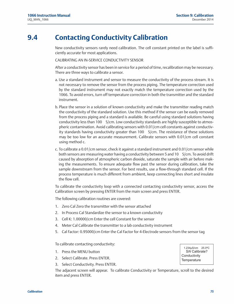
1066 Instruction Manual Section 9: CalibrationLIQ_MAN_1066 December 2014
Calibration 75
Contacting Conductivity Calibration
New conductivity sensors rarely need calibration. The cell constant printed on the label is suffi-
ciently accurate for most applications.
CALIBRATING AN IN-SERVICE CONDUCTIVITY SENSOR
After a conductivity sensor has been in service for a period of time, recalibration may be necessary.
There are three ways to calibrate a sensor.
a. Use a standard instrument and sensor to measure the conductivity of the process stream. It is
not necessary to remove the sensor from the process piping. The temperature correction used
by the standard instrument may not exactly match the temperature correction used by the
1066. To avoid errors, turn off temperature correction in both the transmitter and the standard
instrument.
b. Place the sensor in a solution of known conductivity and make the transmitter reading match
the conductivity of the standard solution. Use this method if the sensor can be easily removed
from the process piping and a standard is available. Be careful using standard solutions having
conductivity less than 100 μS/cm. Low conductivity standards are highly susceptible to atmos-
pheric contamination. Avoid calibrating sensors with 0.01/cm cell constants against conductiv-
ity standards having conductivity greater than 100 μS/cm. The resistance of these solutions
may be too low for an accurate measurement. Calibrate sensors with 0.01/cm cell constant
using method c.
c. To calibrate a 0.01/cm sensor, check it against a standard instrument and 0.01/cm sensor while
both sensors are measuring water having a conductivity between 5 and 10 μS/cm. To avoid drift
caused by absorption of atmospheric carbon dioxide, saturate the sample with air before mak-
ing the measurements. To ensure adequate flow past the sensor during calibration, take the
sample downstream from the sensor. For best results, use a flow-through standard cell. If the
process temperature is much different from ambient, keep connecting lines short and insulate
the flow cell.
To calibrate the conductivity loop with a connected contacting conductivity sensor, access the
Calibration screen by pressing ENTER from the main screen and press ENTER.
The following calibration routines are covered:
1. Zero Cal Zero the transmitter with the sensor attached
2. In Process Cal Standardize the sensor to a known conductivity
3. Cell K: 1.00000/cm Enter the cell Constant for the sensor
4. Meter Cal Calibrate the transmitter to a lab conductivity instrument
5. Cal Factor: 0.95000/cm Enter the Cal Factor for 4-Electrode sensors from the sensor tag
To calibrate contacting conductivity:
1. Press the MENU button
2. Select Calibrate. Press ENTER.
3. Select Conductivity. Press ENTER.
The adjacent screen will appear. To calibrate Conductivity or Temperature, scroll to the desired
item and press ENTER.
9.4
1.234µS/cm 25.0ºC
SN Calibrate?
Conductivity
Temperature

Section 9: Calibration 1066 Instruction ManualDecember 2014 LIQ_MAN_1066
76 Calibration
The following sub-sections show the initial display screen that appears for
each calibration routine. Use the flow diagram for Conductivity calibra-
tion at the end of Sec. 7 and the live screen prompts for each routine to
complete calibration.
The adjacent screen appears after selecting Conductivity calibration:
Entering the Cell ConstantNew conductivity sensors rarely need calibration. The cell constant print-
ed on the label is sufficiently accurate for most applications. The cell con-
stant should be entered:
• When the unit is installed for the first time
• When the probe is replaced
The display screen for entering a cell Constant for the sensor is shown. The default value is dis-
played in bold type.
Zeroing the InstrumentThis procedure is used to compensate for small offsets to the conductivi-
ty signal that are present even when there is no conductivity to be meas-
ured. This procedure is affected by the length of extension cable and
should always be repeated if any changes in extension cable or sensor
have been made. Electrically connect the conductivity probe as it will
actually be used and place the measuring portion of the probe in air. Be
sure the probe is dry.
The adjacent screen will appear after selecting Zero Cal from the
Conductivity Calibration screen:
The adjacent screen will appear if zero Cal is successful. The screen will
return to the conductivity Cal Menu.
The adjacent screen may appear if zero Cal is unsuccessful.
Calibrating the Sensor in a Conductivity Standard (in process cal)This procedure is used to calibrate the sensor and transmitter against a solution of known con-
ductivity. This is done by submerging the probe in the sample of known conductivity, then adjust-
ing the displayed value, if necessary, to correspond to the conductivity value of the sample. Turn
temperature correction off and use the conductivity of the standard. Use a calibrated thermome-
ter to measure temperature. The probe must be cleaned before performing this procedure.
The adjacent screen will appear after selecting In Process Cal from the
Conductivity Calibration screen:
The adjacent screen will appear if In Process Cal is successful. The screen
will return to the conductivity Cal Menu.
The adjacent screen may appear if In Process Cal is unsuccessful. The
screen will return to the conductivity Cal Menu.
9.4.1
9.4.2
9.4.3
1.234µS/cm 25.0ºC
SN Calibration
Zero Cal
In Process Cal
Meter Cal
Cell K: 1.00000/cm
1.234µS/cm 25.0ºC
SN Cell Constant
1.00000 /cm
1.234µS/cm 25.0ºC
SN Zero Cal
In Air
In Water
1.234µS/cm 25.0ºC
SN Zero Cal
Sensor Zero Fail
Offset too high
Press EXIT
1.234µS/cm 25.0ºC
SN Zero Cal
Sensor Zero Done
1.234µS/cm 25.0ºC
SN InProcess Cal
Wait for stable
reading.

1066 Instruction Manual Section 9: CalibrationLIQ_MAN_1066 December 2014
Calibration 77
The adjacent screen will appear if In Process Cal is successful. The screen
will return to the conductivity Cal Menu.
The adjacent screen may appear if In Process Cal is unsuccessful. The
screen will return to the conductivity Cal Menu.
Calibrating the Sensor To A Laboratory Instrument(meter cal)This procedure is used to check and correct the conductivity reading of the 1066 using a labora-
tory conductivity instrument. This is done by submerging the conductivity probe in a bath and
measuring the conductivity of a grab sample of the same bath water with a separate laboratory
instrument. The 1066 reading is then adjusted to match the conductivity reading of the lab instru-
ment.
The adjacent screen will appear after selecting Meter Cal from the
Conductivity Calibration screen:
After pressing ENTER, the display shows the live value measured by the
sensor
If the meter cal is successful the screen will return to the conductivity Cal
Menu.
The adjacent screen will appear if Meter Cal is unsuccessful. The screen will
return to the conductivity Cal Menu.
Cal FactorUpon initial installation and power up, if 4-electrode was selected for the
sensor type in the Quick Start menus, the user enters a Cell Constant and
a “Cal Factor” using the instrument keypad. The cell constant is needed to
convert measured conductance to conductivity as displayed on the trans-
mitter screen. The “Cal Factor” entry is needed increase the accuracy of the live conductivity read-
ings, especially at low conductivity readings below 20uS/cm. Both the Cell Constant and the “Cal
Factor” are printed on the tag attached to the 4-electrode sensor/cable.
9.4.4
9.4.5
1.234µS/cm 25.0ºC
SN InProcess Cal
Calibration
Error
Press EXIT
1.234µS/cm 25.0ºC
SN InProcess Cal
Updated cell
constant:
1.00135/cm
1.234µS/cm 25.0ºC
SN Meter Cal
Use precision
resistors only
1.234µS/cm 25.0ºC
SN Meter Cal
Calibration
Error
Press EXIT
1.234µS/cm 25.0ºC
SN Enter Value
xx.xx kΩ
1.234µS/cm 25.0ºC
SN Cal Factor
0.95000 /cm

Section 9: Calibration 1066 Instruction ManualDecember 2014 LIQ_MAN_1066
78 Calibration
Toroidal Conductivity Calibration
Calibration is the process of adjusting or standardizing the transmitter to a lab test or a calibrated
laboratory instrument, or standardizing to some known reference (such as a conductivity stan-
dard). This section contains procedures for the first time use and for routine calibration of the
1066 transmitter.
To calibrate the conductivity loop with a connected contacting conductivity sensor, access the
Calibration screen by pressing ENTER from the main screen and press ENTER.
The following calibration routines are covered:
1. Zero Cal Zero the transmitter with the sensor attached
2. In Process Cal Standardize the sensor to a known conductivity
3. Cell K: 1.00000/cm Enter the cell Constant for the sensor
4. Meter Cal Calibrate the transmitter to a lab conductivity instrument
To calibrate toroidal conductivity:
1. Press the MENU button
2. Select Calibrate. Press ENTER.
3. Select Conductivity. Press ENTER.
The adjacent screen will appear. To calibrate Toroidal Conductivity or Temperature, scroll to the
desired item and press ENTER
The following sub-sections show the initial display screen that appears for each calibration routine.
Use the flow diagram for Conductivity calibration at the end of Sec. 7 and the live screen prompts
to complete calibration.
The adjacent screen appears after selecting Conductivity calibration:
Entering the Cell ConstantNew toroidal sensors always need to be calibrated. The cell constant provided on the sensor label
is a nominal value and does not need to be entered.
This procedure sets up the transmitter for the probe type connected to the transmitter. Each type
of probe has a specific cell constant
The display screen for entering a cell constant for the sensor is shown.
The default value is displayed in bold type.
9.5
9.5.1
1.234µS/cm 25.0ºC
Calibration
Zero Cal
In Process Cal
Cell K: 2.7000/cm
1.234µS/cm 25.0ºC
Cell Constant
2.7000/cm

1066 Instruction Manual Section 9: CalibrationLIQ_MAN_1066 December 2014
Calibration 79
Zeroing the InstrumentThis procedure is used to compensate for small offsets to the conductivity signal that are present
even when there is no conductivity to be measured. This procedure is affected by the length of
extension cable and should always be repeated if any changes in extension cable or sensor have
been made. Electrically connect the conductivity probe as it will actually be used and place the
measuring portion of the probe in air.
The adjacent screen will appear after selecting Zero Cal from the
Conductivity Calibration screen:
The adjacent screen will appear if zero Cal is successful. The screen will
return to the conductivity Cal Menu.
The adjacent screen may appear if zero Cal is unsuccessful.
Calibrating the Sensor in a Conductivity Standard(in process cal)This procedure is used to check and correct the conductivity reading of the 1066 to ensure that
the reading is accurate. This is done by submerging the probe in the sample of known conductivi-
ty, then adjusting the displayed value, if necessary, to correspond to the conductivity value of the
sample. The probe must be cleaned before performing this procedure. The temperature reading
must also be checked and standardized if necessary, prior to performing this procedure.
The adjacent screen will appear after selecting In Process Cal from the
Conductivity Calibration screen:
The following screen will appear if In Process Cal is successful. The screen
will return to the conductivity Cal Menu.
This screen may appear if In Process Cal is unsuccessful. The screen will
return to the conductivity Cal Menu.
9.5.2
9.5.3
1.234µS/cm 25.0ºC
SN Zero Cal
In Air
In Water
1.234µS/cm 25.0ºC
SN Zero Cal
Sensor Zero Fail
Offset too high
Press EXIT
1.234µS/cm 25.0ºC
SN Zero Cal
Sensor Zero Done
1.234µS/cm 25.0ºC
SN InProcess Cal
Wait for stable
reading.
1.234µS/cm 25.0ºC
SN InProcess Cal
Calibration
Error
Press EXIT
1.234µS/cm 25.0ºC
SN InProcess Cal
Updated cell
constant:
3.01350/cm

Section 9: Calibration 1066 Instruction ManualDecember 2014 LIQ_MAN_1066
80 Calibration
Calibration – Chlorine
The 1066 can measure three variants of Chlorine:
• Free Chlorine
• Total Chlorine
• Monochloramine
The section describes how to calibrate any compatible amperometric chlorine sensor. The follow-
ing calibration routines are covered in the family of supported Chlorine sensors:
• Air Cal
• Zero Cal
• In Process Cal
Calibration – Free ChlorineA free chlorine sensor generates a current directly proportional to the concentration of free chlo-
rine in the sample. Calibrating the sensor requires exposing it to a solution containing no chlorine
(zero standard) and to a solution containing a known amount of chlorine (full-scale standard). The
zero calibration is necessary because chlorine sensors, even when no chlorine is in the sample,
generate a small current called the residual current. The transmitter compensates for the residual
current by subtracting it from the measured current before converting the result to a chlorine
value. New sensors require zeroing before being placed in service, and sensors should be zeroed
whenever the electrolyte solution is replaced.
To calibrate the chlorine sensor, access the Calibration screen by pressing ENTER from the main
screen and press ENTER.
The following calibration routines are covered:
1. Zero Cal Zeroing the sensor in solution with zero free chlorine
2. Grab Cal Standardizing to a sample of known free chlorine concentration
To calibrate free chlorine:
1. Press the MENU button
2. Select Calibrate. Press ENTER.
3. Select Free Chlorine. Press ENTER.
The adjacent screen will appear. To calibrate Free Chlorine or Temperature,
scroll to the desired item and press ENTER.
The following sub-sections show the initial display screen that appears for each calibration routine.
Use the flow diagram for Chlorine calibration at the end of Sec. 7 and the live screen prompts to
complete calibration.
The adjacent screen appears after selecting Free Chlorine calibration:
9.6
9.6.1
1.234µS/cm 25.0ºC
SN Calibrate?
Free Chlorine
Temperature
1.234µS/cm 25.0ºC
SN Calibration
Zero Cal
In Process Cal
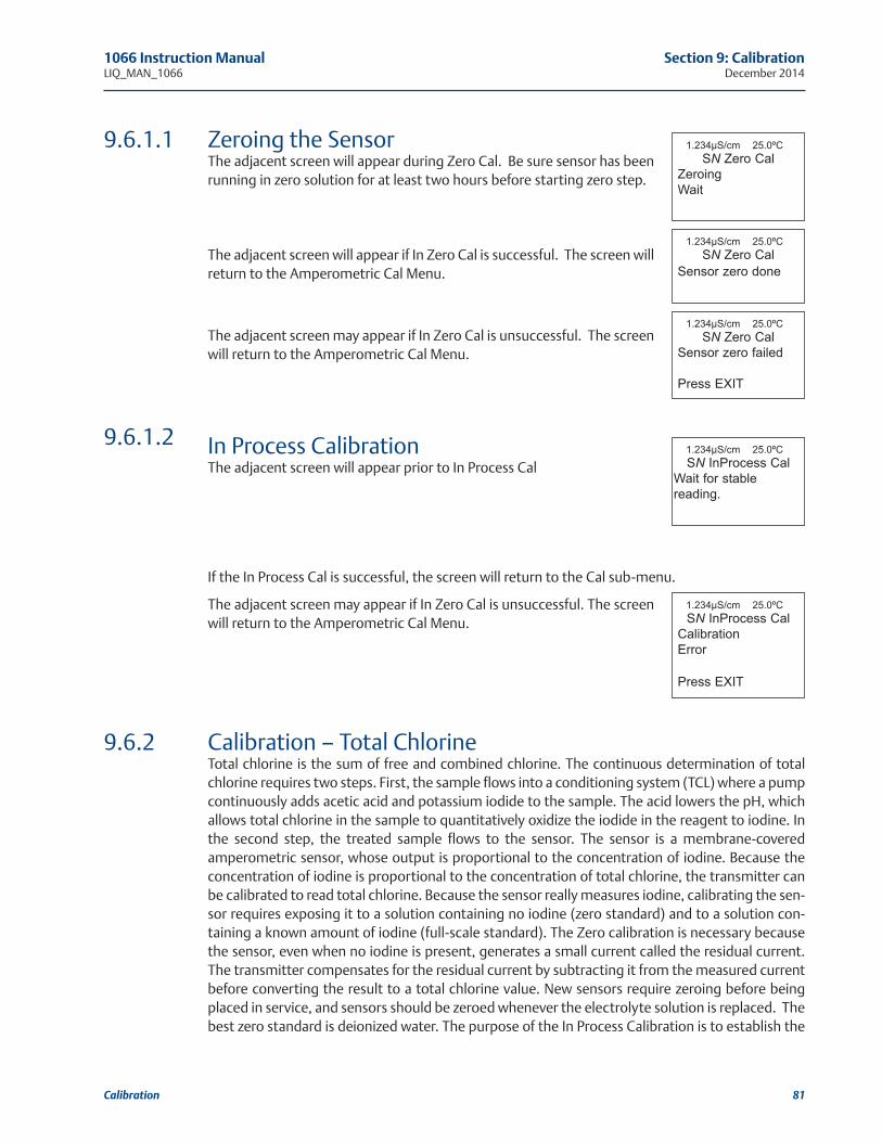
1066 Instruction Manual Section 9: CalibrationLIQ_MAN_1066 December 2014
Calibration 81
Zeroing the SensorThe adjacent screen will appear during Zero Cal. Be sure sensor has been
running in zero solution for at least two hours before starting zero step.
The adjacent screen will appear if In Zero Cal is successful. The screen will
return to the Amperometric Cal Menu.
The adjacent screen may appear if In Zero Cal is unsuccessful. The screen
will return to the Amperometric Cal Menu.
In Process CalibrationThe adjacent screen will appear prior to In Process Cal
If the In Process Cal is successful, the screen will return to the Cal sub-menu.
The adjacent screen may appear if In Zero Cal is unsuccessful. The screen
will return to the Amperometric Cal Menu.
Calibration – Total ChlorineTotal chlorine is the sum of free and combined chlorine. The continuous determination of total
chlorine requires two steps. First, the sample flows into a conditioning system (TCL) where a pump
continuously adds acetic acid and potassium iodide to the sample. The acid lowers the pH, which
allows total chlorine in the sample to quantitatively oxidize the iodide in the reagent to iodine. In
the second step, the treated sample flows to the sensor. The sensor is a membrane-covered
amperometric sensor, whose output is proportional to the concentration of iodine. Because the
concentration of iodine is proportional to the concentration of total chlorine, the transmitter can
be calibrated to read total chlorine. Because the sensor really measures iodine, calibrating the sen-
sor requires exposing it to a solution containing no iodine (zero standard) and to a solution con-
taining a known amount of iodine (full-scale standard). The Zero calibration is necessary because
the sensor, even when no iodine is present, generates a small current called the residual current.
The transmitter compensates for the residual current by subtracting it from the measured current
before converting the result to a total chlorine value. New sensors require zeroing before being
placed in service, and sensors should be zeroed whenever the electrolyte solution is replaced. The
best zero standard is deionized water. The purpose of the In Process Calibration is to establish the
9.6.1.1
9.6.1.2
9.6.2
1.234µS/cm 25.0ºC
SN Zero Cal
Sensor zero done
1.234µS/cm 25.0ºC
SN Zero Cal
Zeroing
Wait
1.234µS/cm 25.0ºC
SN Zero Cal
Sensor zero failed
Press EXIT
1.234µS/cm 25.0ºC
SN InProcess Cal
Wait for stable
reading.
1.234µS/cm 25.0ºC
SN InProcess Cal
Calibration
Error
Press EXIT

Section 9: Calibration 1066 Instruction ManualDecember 2014 LIQ_MAN_1066
82 Calibration
slope of the calibration curve. Because stable total chlorine standards do not exist, the sensor
must be calibrated against a test run on a grab sample of the process liquid. Several manufactur-
ers offer portable test kits for this purpose.
To calibrate the chlorine sensor, access the Calibration screen by pressing ENTER from the main
screen, and press ENTER.
The following calibration routines are covered:
1. Zero Cal Zeroing the sensor in solution with zero total chlorine
2. Grab Cal Standardizing to a sample of known total chlorine concentration
To calibrate total chlorine:
1. Press the MENU button
2. Select Calibrate. Press ENTER.
3. Select Total Chlorine. Press ENTER.
The adjacent screen will appear. To calibrate Total Chlorine or
Temperature, scroll to the desired item and press ENTER
The following sub-sections provide you with the initial display screen that appears for each cali-
bration routine. Use the flow diagram for Chlorine calibration at the end
of Sec. 9 and the live screen prompts to complete calibration.
This adjacent screen appears after selecting Total Chlorine calibration:
Zeroing the SensorThe adjacent screen will appear during Zero Cal. Be sure sensor has been
running in zero solution for at least two hours before starting zero step.
The adjacent screen will appear if In Zero Cal is successful. The screen will
return to the Amperometric Cal Menu.
The adjacent screen may appear if In Zero Cal is unsuccessful. The screen
will return to the Amperometric Cal Menu.
In Process CalibrationThe adjacent screen will appear prior to In Process Cal
If the In Process Cal is successful, the screen will return to the Cal sub-
menu.
The adjacent screen may appear if In Process Cal is unsuccessful. The
screen will return to the Amperometric Cal Menu.
9.6.2.1
9.6.2.2
1.234µS/cm 25.0ºC
SN Calibrate?
Total Chlorine
Temperature
1.234µS/cm 25.0ºC
SN Zero Cal
Zeroing
Wait
1.234µS/cm 25.0ºC
SN Calibration
Zero Cal
In Process Cal
1.234µS/cm 25.0ºC
SN Zero Cal
Sensor zero failed
Press EXIT
1.234µS/cm 25.0ºC
SN InProcess Cal
Calibration error
Press EXIT
1.234µS/cm 25.0ºC
SN InProcess Cal
Wait for stable
reading.
1.234µS/cm 25.0ºC
SN Zero Cal
Sensor zero done

1066 Instruction Manual Section 9: CalibrationLIQ_MAN_1066 December 2014
Calibration 83
Calibration – MonochloromineA monochloramine sensor generates a current directly proportional to the concentration of
monochloramine in the sample. Calibrating the sensor requires exposing it to a solution contain-
ing no monochloramine (zero standard) and to a solution containing a known amount of mono-
chloramine (full-scale standard). The Zero calibration is necessary because monochloramine sen-
sors, even when no monochloramine is in the sample, generate a small current called the residual
or zero current. The transmitter compensates for the residual current by subtracting it from the
measured current before converting the result to a monochloramine value. New sensors require
zeroing before being placed in service, and sensors should be zeroed whenever the electrolyte
solution is replaced. The best zero standard is deionized water. The purpose of the In Process cali-
bration is to establish the slope of the calibration curve. Because stable monochloramine stan-
dards do not exist, the sensor must be calibrated against a test run on a grab sample of the process
liquid. Several manufacturers offer portable test kits for this purpose.
To calibrate the chlorine sensor, access the Calibration screen by pressing ENTER from the main
screen, and press ENTER.
The following calibration routines are covered:
1. Zero Cal Zeroing the sensor in solution with zero total chlorine
2. Grab Cal Standardizing to a sample of known monochloramine concentration
To calibrate monochloramine:
1. Press the MENU button
2. Select Calibrate. Press ENTER.
3. Select Monochloramine. Press ENTER.
The adjacent screen will appear. To calibrate Monochloramine or
Temperature, scroll to the desired item and press ENTER.
The following sub-sections provide you with the initial display screen that appears for each cali-
bration routine. Use the flow diagram for Chlorine calibration at the end of Sec. 9 and the live
screen prompts to complete calibration.
The adjacent screen appears after selecting Monochloramine calibration:
9.6.3
1.234µS/cm 25.0ºC
SN Calibration
Zero Cal
In Process Cal
1.234µS/cm 25.0ºC
SN Calibrate?
Monochloramine
Temperature

Section 9: Calibration 1066 Instruction ManualDecember 2014 LIQ_MAN_1066
84 Calibration
Zeroing the SensorThe adjacent screen will appear during Zero Cal. Be sure sensor has been
running in zero solution for at least two hours before starting zero step.
The adjacent screen will appear if In Zero Cal is successful. The screen will
return to the Amperometric Cal Menu.
The adjacent screen may appear if In Zero Cal is unsuccessful. The screen
will return to the Amperometric Cal Menu.
In Process CalibrationThe adjacent screen will appear prior to In Process Cal
If the In Process Cal is successful, the screen will return to the Cal sub-
menu.
The adjacent screen may appear if In Process Cal is unsuccessful. The
screen will return to the Amperometric Cal Menu.
Calibration – oxygenOxygen sensors generate a current directly proportional to the concentration of dissolved oxygen
in the sample. Calibrating the sensor requires exposing it to a solution containing no oxygen (zero
standard) and to a solution containing a known amount of oxygen (full-scale standard). The Zero
Calibration is necessary because oxygen sensors, even when no oxygen is present in the sample,
generate a small current called the residual current. The transmitter compensates for the residual
current by subtracting it from the measured current before converting the result to a dissolved
oxygen value. New sensors require zeroing before being placed in service, and sensors should be
zeroed whenever the electrolyte solution is replaced. The recommended zero standard is 5% sodi-
um sulfite in water, although oxygen-free nitrogen can also be used. The 499A TrDO sensor, used
for the determination of trace (ppb) oxygen levels, has very low residual current and does not nor-
mally require zeroing. The residual current in the 499A TrDO sensor is equivalent to less than 0.5
ppb oxygen. The purpose of the In Process Calibration is to establish the slope of the calibration
curve. Because the solubility of atmospheric oxygen in water as a function of temperature and
barometric pressure is well known, the natural choice for a full-scale standard is air-saturated
water. However, air-saturated water is difficult to prepare and use, so the universal practice is to
use air for calibration. From the point of view of the oxygen sensor, air and air-saturated water are
9.6.4
9.6.5
9.7
1.234µS/cm 25.0ºC
SN Zero Cal
Zeroing
Wait
1.234µS/cm 25.0ºC
SN Zero Cal
Sensor zero failed
Press EXIT
1.234µS/cm 25.0ºC
SN Zero Cal
Sensor zero done
1.234µS/cm 25.0ºC
SN InProcess Cal
Calibration
Error
Press EXIT
1.234µS/cm 25.0ºC
SN InProcess Cal
Wait for stable
reading.

1066 Instruction Manual Section 9: CalibrationLIQ_MAN_1066 December 2014
Calibration 85
identical. The equivalence comes about because the sensor really measures the chemical poten-
tial of oxygen. Chemical potential is the force that causes oxygen molecules to diffuse from the
sample into the sensor where they can be measured. It is also the force that causes oxygen mole-
cules in air to dissolve in water and to continue to dissolve until the water is saturated with oxygen.
Once the water is saturated, the chemical potential of oxygen in the two phases (air and water) is
the same. Oxygen sensors generate a current directly proportional to the rate at which oxygen
molecules diffuse through a membrane stretched over the end of the sensor. The diffusion rate
depends on the difference in chemical potential between oxygen in the sensor and oxygen in the
sample. An electrochemical reaction, which destroys any oxygen molecules entering the sensor,
keeps the concentration (and the chemical potential) of oxygen inside the sensor equal to zero.
Therefore, the chemical potential of oxygen in the sample alone determines the diffusion rate and
the sensor current. When the sensor is calibrated, the chemical potential of oxygen in the stan-
dard determines the sensor current. Whether the sensor is calibrated in air or air-saturated water
is immaterial. The chemical potential of oxygen is the same in either phase. Normally, to make the
calculation of solubility in common units (like ppm DO) simpler, it is convenient to use water-sat-
urated air for calibration. Automatic air calibration is standard. The user simply exposes the sen-
sor to water-saturated air. The transmitter monitors the sensor current. When the current is sta-
ble, the transmitter stores the current and measures the temperature using a temperature ele-
ment inside the oxygen sensor. The user must enter the barometric pressure. From the tempera-
ture the transmitter calculates the saturation vapor pressure of water. Next, it calculates the pres-
sure of dry air by subtracting the vapor pressure from the barometric pressure. Using the fact
that dry air always contains 20.95% oxygen, the transmitter calculates the partial pressure of oxy-
gen. Once the transmitter knows the partial pressure of oxygen, it uses the Bunsen coefficient to
calculate the equilibrium solubility of atmospheric oxygen in water at the prevailing temperature.
At 25°C and 760 mm Hg, the equilibrium solubility is 8.24 ppm. Often it is too difficult or messy
to remove the sensor from the process liquid for calibration. In this case, the sensor can be cali-
brated against a measurement made with a portable laboratory instrument. The laboratory
instrument typically uses a membrane-covered amperometric sensor that has been calibrated
against water-saturated air.
To calibrate the oxygen sensor, access the Calibration screen by pressing ENTER from the main
screen, select and press ENTER.
The following calibration routines are covered:
1. Zero Cal Zeroing the sensor in a medium with zero oxygen
2. Air Cal Calibrating the sensor in a water-saturated air sample
3. In Process Cal Standardizing to a sample of known oxygen concentration
4. Sen@ 25°C:2500nA/ppm Entering a known slope value for sensor response
To calibrate oxygen:
1. Press the MENU button
2. Select Calibrate. Press ENTER.
3. Select Oxygen. Press ENTER.
The adjacent screen will appear. To calibrate Oxygen or Temperature,
scroll to the desired item and press ENTER
1.234µS/cm 25.0ºC
SN Calibrate?
Oxygen
Temperature

Section 9: Calibration 1066 Instruction ManualDecember 2014 LIQ_MAN_1066
86 Calibration
The following sub-sections provide you with the initial display screen that appears for each cali-
bration routine. Use the flow diagram for Oxygen calibration at the end of Sec. 9 and the live
screen prompts for each routine to complete calibration.
The adjacent screen appears after selecting Oxygen calibration:
Air calibration criteria can be changed.
The following criteria can be adjusted:
• Stabilization time (default 10 sec.)
• Stabilization pH value (default 0.05 ppm)
• Salinity of the solution to be measured (default 00.0 parts per thousand)
The adjacent screen will appear to allow adjustment of these criteria:
Zeroing the SensorThe adjacent screen will appear during Zero Cal
The adjacent screen will appear if In Zero Cal is successful. The screen will
return to the Amperometric Cal Menu.
The adjacent screen may appear if In Zero Cal is unsuccessful. The screen
will return to the Amperometric Cal Menu.
Calibrating the Sensor in AirThe adjacent screen will appear prior to Air Cal
The adjacent screen will appear if In Air Cal is successful. The screen will
return to the Amperometric Cal Menu.
The adjacent screen may appear if In Air Cal is unsuccessful. The screen
will return to the Amperometric Cal Menu.
9.7.1
9.7.2
1.234µS/cm 25.0ºC
SN Calibration
Air Cal
Zero Cal
In Process Cal
Sen@ 25°C:2500nA/ppm
Zero Current: 1234nA
1.234µS/cm 25.0ºC
SN Setup
Stable Time: 10 sec
Stable Delta: 0.05 ppm
Salinity: 00.0 ‰
1.234µS/cm 25.0ºC
SN Air Cal
Failure
Check Sensor
Press EXIT
1.234µS/cm 25.0ºC
SN Air Cal
Done
1.234 nA
SN Zero Cal
Sensor zero done
1.234µS/cm 25.0ºC
SN Air Cal
Start Calibration
Setup
1.234 nA
SN Zero Cal
Sensor zero failed
Press EXIT
1.234 nA
SN Zero Cal
Zeroing
Wait

1066 Instruction Manual Section 9: CalibrationLIQ_MAN_1066 December 2014
Calibration 87
Calibrating the Sensor Against A Standard Instrument(in process cal)The adjacent screen will appear prior to In Process Cal
If the In Process Cal is successful, the screen will return to the Cal sub-menu.
The adjacent screen may appear if In Zero Cal is unsuccessful. The screen will return to the
Amperometric Cal Menu.
Calibration – ozoneAn ozone sensor generates a current directly proportional to the concentration of ozone in the
sample. Calibrating the sensor requires exposing it to a solution containing no ozone (zero stan-
dard) and to a solution containing a known amount of ozone (full-scale standard). The Zero
Calibration is necessary because ozone sensors, even when no ozone is in the sample, generate a
small current called the residual or zero current. The transmitter compensates for the residual cur-
rent by subtracting it from the measured current before converting the result to an ozone value.
New sensors require zeroing before being placed in service, and sensors should be zeroed when-
ever the electrolyte solution is replaced. The best zero standard is deionized water. The purpose of
the In Process Calibration is to establish the slope of the calibration curve. Because stable ozone
standards do not exist, the sensor must be calibrated against a test run on a grab sample of the
process liquid. Several manufacturers offer portable test kits for this purpose.
To calibrate the ozone sensor, access the Calibration screen by pressing ENTER from the main
screen, select and press ENTER.
The following calibration routines are covered:
1. Zero Cal Zeroing the sensor in solution with zero total chlorine
2. Grab Cal Standardizing to a sample of known ozone concentration
To calibrate ozone:
1. Press the MENU button
2. Select Calibrate. Press ENTER.
3. Select Ozone. Press ENTER.
The adjacent screen will appear. To calibrate Ozone or Temperature, scroll
to the desired item and press ENTER.
9.7.3
9.8
1.234µS/cm 25.0ºC
SN Calibrate?
Ozone
Temperature

The following sub-sections provide you with the initial display screen that appears for each cali-
bration routine. Use the flow diagram for ozone calibration at the end of Sec. 9 and the live
screen prompts to complete calibration.
The adjacent screen appears after selecting Ozone calibration:
Zeroing the SensorThe following screen will appear during Zero Cal
The following screen will appear if In Zero Cal is successful. The screen will
return to the Amperometric Cal Menu.
The following screen may appear if In Zero Cal is unsuccessful. The screen
will return to the Amperometric Cal Menu.
In Process CalibrationThe following screen will appear after selecting In Process Cal
If the In Process Cal is successful, the screen will return to the Cal sub-
menu. The following screen may appear if In Zero Cal is unsuccessful. The
screen will return to the Amperometric Cal Menu.
9.8.1
9.8.2
1.234 nA
SN Zero Cal
Zeroing
Wait
1.234µS/cm 25.0ºC
SN Calibration
Zero Cal
In Process Cal
1.234 nA
SN Zero Cal
Sensor zero failed
Press EXIT
1.234 nA
SN Zero Cal
Sensor zero done
1.234µS/cm 25.0ºC
SN InProcess Cal
Calibration
Error
Press EXIT
1.234µS/cm 25.0ºC
SN InProcess Cal
Wait for stable
reading.
Section 9: Calibration 1066 Instruction ManualDecember 2014 LIQ_MAN_1066
88 Calibration

1066 Instruction Manual Section 9: CalibrationLIQ_MAN_1066 December 2014
Calibration 89
Calibrating Temperature
Most liquid analytical measurements require temperature compensation (except ORP and Redox).
The 1066 performs temperature compensation automatically by applying internal temperature
correction algorithms. Temperature correction can also be turned off. If temperature correction is
off, the 1066 uses the manual temperature entered by the user in all temperature correction cal-
culations.
To calibrate temperature, access the Calibration screen by pressing ENTER from the main screen,
select Temperature and press ENTER.
The following calibration routine is covered:
1. Temperature with manual temperature entry
To calibrate temperature:
1. Press the MENU button
2. Select Calibrate. Press ENTER.
3. Select Temperature. Press ENTER.
The adjacent screen will appear.
The following sub-section provides you with the initial display screen that appears for temperature
calibration. Use the flow diagram for Temp calibration at the end of Sec. 7 to complete calibration.
Calibration
The adjacent screen will appear during Temperature Cal.
If the sensor Temperature offset is greater than 5 ºC from the default
value, the following screen will appear:
You may continue by selecting Yes or suspend this operation by
selecting No.
If the Temp Cal is successful, the screen will return to the Cal Menu.
note: To select automatic or manual temp compensation or to program temperature units as °C
or °F, refer to Sec. 7.3 – Programming Temperature in this manual.
9.9
9.9.1
1.234µS/cm 25.0ºC
SN Calibrate
+025.0°C
1.234µS/cm 25.0ºC
SN Temp Offset > 5°C
Continue?
No
Yes
1.234µS/cm 25.0ºC
SN Calibrate
Cal in progress.
Please wait.

1
.234
µS
/cm
2
5.0º
C
Cal
ibra
te?
1.23
4µS
/cm
2
5.0º
C
SN
Cal
ibra
te?
Fre
e C
hlor
ine
T ota
l Chl
orin
eC
hlor
amin
eO
zone
O
xyge
n
OR
PR
edox
C
ondu
ctiv
ity
TD
SS
alin
ityN
aOH
HC
lLo
w H
2SO
4H
igh
H2S
O4
NaC
lR
esis
tivity
C
usto
m C
onc’
nTe
mpe
ratu
re
1
.234
µS
/cm
2
5.0º
C
SN
pH
Cal
Buf
fer
Cal
Sta
ndar
dize
Slo
pe:
59.1
6mV
/pH
Offs
et:
600
mV
1
.234
µS
/cm
2
5.0º
C
Cha
ngin
g sl
ope
over
rides
bu
ffer
Cal
1
.234
µS
/cm
2
5.0º
C
SN
pH
Offs
et
060
mV
1.2
34µ
S/c
m
25.
0ºC
SN
pH
Slo
pe@
25ºC
59.1
6 m
V/p
H
pH
1.2
34µ
S/c
m
25.
0ºC
Cha
ngin
g of
fset
over
rides
bu
ffer
Cal
1.2
34µ
S/c
m
25.
0ºC
SN
Sta
ndar
dize
Cal
in p
rogr
ess.
Ple
ase
wai
t.
1.2
34µ
S/c
m
25.
0ºC
SN
Sta
ndar
dize
Offs
et E
rror
C
alcu
late
d:
96m
VM
ax:
60m
V
Pre
ss E
XIT
1
.234
µS
/cm
2
5.0º
C
SN
Ent
er V
alue
07.0
0pH
1.2
34µ
S/c
m
25.
0ºC
Man
ual B
uffe
rM
07.0
0pH
1
.234
µS
/cm
2
5.0º
C
SN
pH
Man
ual C
al
Buf
fer
1B
uffe
r 2
1.2
34µ
S/c
m
25.
0ºC
SN
Man
ual C
al
Cal
in p
rogr
ess.
Ple
ase
wai
t.
1.2
34µ
S/c
m
25.
0ºC
SN
pH
Man
ual C
al
Slo
pe:
59.
16m
V/p
H
Offs
et:
60
mV
1
.234
µS
/cm
2
5.0º
C
SN
pH
Buf
fer
Cal
Aut
o M
anua
l
1.2
34µ
S/c
m
25.
0ºC
SN
pH
Aut
o C
al
Sta
rt A
utoC
alS
etup
1.2
34µ
S/c
m
25.
0ºC
SN
Set
up
Sta
ble
Tim
e:
10
sec
Sta
ble
Del
ta:
0.02
pH
Buf
fer:
S
tand
ard
1.2
34µ
S/c
m
25.
0ºC
SN
pH
Aut
o C
al
Pla
ce S
enso
r in
B
uffe
r 1
Pre
ss E
NT
ER
1.2
34µ
S/c
m
25.
0ºC
SN
Buf
fer
Sta
ndar
dD
IN 1
9267
Ingo
ldM
erck
1.2
34µ
S/c
m
25.
0ºC
SN
pH
Aut
o C
al
Pla
ce S
enso
r in
B
uffe
r 1
Pre
ss E
NT
ER
1.2
34µ
S/c
m
25.
0ºC
SN
pH
Aut
o B
uffe
r 1
Wai
t
1.2
34µ
S/c
m
25.
0ºC
SN
pH
Aut
o B
uffe
r 1
07.0
1pH
1.2
34µ
S/c
m
25.
0ºC
SN
pH
Aut
o B
uffe
r 2
Wai
t
1.2
34µ
S/c
m
25.
0ºC
SN
pH
Aut
o B
uffe
r 2
10.0
1pH
1.2
34µ
S/c
m
25.
0ºC
SN
pH
Aut
o C
al
Cal
in p
rogr
ess.
Ple
ase
wai
t.
1.2
34µ
S/c
m
25.
0ºC
SN
pH
Aut
o C
al
Slo
pe:
59.1
6 m
V/p
H
O
ffset
:
60
mV
M A I N M E N U
C a l i b r a t e
Section 9: Calibration 1066 Instruction ManualDecember 2014 LIQ_MAN_1066
FIGurE 9-1. Calibrate ph
90 Calibration

1066 Instruction Manual Section 9: CalibrationLIQ_MAN_1066 December 2014
Calibration 91
1.23
4µS
/cm
2
5.0º
C
Cal
ibra
te?
TDS
Sal
inity
NaO
HH
Cl
Low
H2S
O4
Hig
h H
2SO
4N
aCl
Res
istiv
ity’
Cus
tom
Con
c’n
Tem
pera
ture
1.23
4µS
/cm
2
5.0º
C
SN
Cal
ibra
te?
Free
Chl
orin
epH
Inde
pend
. Fre
e C
lTo
tal C
hlor
ine
Chl
oram
ine
Ozo
ne
Oxy
gen
pH OR
PR
edox
1.2
34µS
/cm
2
5.0º
C
SN
Cal
ibra
tion
Zero
Cal
In P
roce
ss C
alM
eter
Cal
Cel
l K:
1.00
000/
cm
1.
234µ
S/c
m
25.
0ºC
SN
Zer
o C
al
Zero
ing
Wai
t
1.23
4µS
/cm
2
5.0º
C
SN
Met
er C
al
Use
pre
cisi
onre
sist
ors
only
1.23
4µS
/cm
2
5.0º
C
SN
Ent
er V
alue
xx.x
x kΩ
1.23
4µS
/cm
2
5.0º
C
SN
Met
er C
al
Cal
in p
rogr
ess.
Ple
ase
wai
t.
1.2
34µS
/cm
2
5.0º
C
SN
Zer
o C
al
In A
irIn
Wat
er
1.23
4µS
/cm
2
5.0º
C
SN
InP
roce
ss C
al
Pre
ss E
NTE
R if
read
ing
is s
tabl
e.
1.23
4µS
/cm
2
5.0º
C
SN
InP
roce
ss C
al
Cal
in p
rogr
ess.
Ple
ase
wai
t.
1.23
4µS
/cm
2
5.0º
C
SN
InP
roce
ss C
al
Upd
ated
c
ell
cons
tant
: 1.
0013
5/cm
1.23
4µS
/cm
2
5.0º
C
SN
InP
roce
ss C
alW
ait f
or s
tabl
ere
adin
g.
1.23
4µS
/cm
2
5.0º
C
SN
Zer
o C
al
Sen
sor m
ust b
edr
y an
d in
air
1.23
4µS
/cm
2
5.0º
C
SN
InP
roce
ss C
al
Take
sam
ple;
Pre
ss E
NTE
R.
1.23
4µS
/cm
2
5.0º
C
SN
Zer
o C
al
Sen
sor m
ust b
eIn
0%
sol
utio
n
1.23
4µS
/cm
2
5.0º
C
SN
Zer
o C
alZe
roin
gW
ait
1.23
4µS
/cm
2
5.0º
C
SN
Zer
o C
al
Sen
sor Z
ero
Don
e
1.23
4µS
/cm
2
5.0º
C
SN
Ent
er V
alue
10.0
0 uS
/cm
Con
duct
ivity
TDS
Sal
inity
NaO
HH
Cl
Low
H2S
O4
Hig
h H
2SO
4N
aCl
Res
istiv
ity’
Cus
tom
Con
c’n
M A I N M E N U
C a l i b r a t e
Figure 9-2. Calibrate Contacting and Toroidal Conductivity

1.23
4µS
/cm
2
5.0º
C
Cal
ibra
te?
TDS
Sal
inity
NaO
HH
Cl
Low
H2S
O4
Hig
h H
2SO
4N
aCl
Res
istiv
ity’
Cus
tom
Con
c’n
Tem
pera
ture
1.23
4µS
/cm
2
5.0º
C
SN
InP
roce
ss C
al
Cal
in p
rogr
ess.
Ple
ase
wai
t.
1.23
4µS
/cm
2
5.0º
C
SN
Cal
ibra
te?
Free
Chl
orin
epH
Inde
pend
. Fre
e C
lTo
tal C
hlor
ine
Chl
oram
ine
Ozo
ne
Oxy
gen
pH OR
PR
edox
Con
duct
ivity
1.23
4µS
/cm
2
5.0º
C
SN
Cal
ibra
tion
Zero
Cal
In P
roce
ss C
al
1.23
4µS
/cm
2
5.0º
C
SN
Ent
er V
alue
10.0
0 pp
m
1.23
4µS
/cm
2
5.0º
C
SN
Zer
o C
al
Sen
sor z
ero
done
1.2
34µS
/cm
2
5.0º
C
SN
Zer
o C
alZe
roin
gW
ait
1.23
4µS
/cm
2
5.0º
C
SN
InP
roce
ss C
al
Wai
t for
sta
ble
read
ing
1.23
4µS
/cm
2
5.0º
C
SN
InP
roce
ss C
al
Pre
ss E
NTE
R if
read
ing
is s
tabl
e.
1.23
4µS
/cm
2
5.0º
C
SN
InP
roce
ss C
al
Take
sam
ple;
Pre
ss E
NTE
R.
Free
Chl
orin
eTo
tal C
hlor
ine
Chl
oram
ine
M A I N M E N U
C a l i b r a t e
Section 9: Calibration 1066 Instruction ManualDecember 2014 LIQ_MAN_1066
92 Calibration
Figure 9-3. Calibrate Free Chlorine, Total Chlorine, and Monochloramine

1066 Instruction Manual Section 9: CalibrationLIQ_MAN_1066 December 2014
Calibration 93
1.23
4µS
/cm
2
5.0º
C
SN
Cal
ibra
te?
Free
Chl
orin
eTo
tal C
hlor
ine
Chl
oram
ine
Ozo
ne
Oxy
gen
pH OR
PR
edox
Con
duct
ivity
1.23
4µS
/cm
2
5.0º
C
Cal
ibra
te?
TDS
Sal
inity
NaO
HH
Cl
Low
H2S
O4
Hig
h H
2SO
4N
aCl
Res
istiv
ityC
usto
mC
onc’
n
Tem
pera
ture
1.2
34µS
/cm
2
5.0º
C
SN
Cal
ibra
tion
Air
Cal
Zero
Cal
In P
roce
ss C
alS
en@
25°
C:2
500n
A/p
pm
Zero
Cur
rent
: 12
34nA
1.23
4µS
/cm
2
5.0º
C
Air
Cal
W
ait
1.23
4µS
/cm
2
5.0º
C
SN
Air
Cal
D
one
1.2
34µS
/cm
2
5.0º
C
SN
Zer
o C
al
Sen
sor z
ero
done
1.23
4µS
/cm
2
5.0º
C
SN
InP
roce
ss C
al
Cal
in p
rogr
ess.
Ple
ase
wai
t.
1.23
4µS
/cm
2
5.0º
C
SN
Ent
er V
alue
10.0
0 pp
m
1.2
34µS
/cm
2
5.0º
C
SN
InP
roce
ss C
al
Wai
t for
sta
ble
read
ing
1.2
34µS
/cm
2
5.0º
C
SN
InP
roce
ss C
al
Pre
ss E
NTE
R if
read
ing
is s
tabl
e.
1.23
4µS
/cm
2
5.0º
C
SN
InP
roce
ss C
alTa
ke s
ampl
e;P
ress
EN
TER
.
1.23
4µS
/cm
2
5.0º
C
SN
Air
Cal
Sta
rt C
alib
ratio
nS
etup
1.23
4µS
/cm
2
5.0º
C
SN
Set
up
Sta
ble
Tim
e:
10
sec
Sta
ble
Del
ta:
0.0
5 pp
m
Sal
inity
:
00.
0 ‰
1.23
4µS
/cm
2
5.0º
C
SN
Air
Pre
ssur
e
760
mm
Hg
1.2
34µS
/cm
2
5.0º
C
SN
Zer
o C
al
Zero
ing
Wai
t
1.23
4µS
/cm
2
5.0º
C
SN
Sta
ble
Tim
e 10
sec
1.23
4µS
/cm
2
5.0º
C
SN
Sta
ble
Del
ta
0.05
ppm
1.23
4µS
/cm
2
5.0º
C
SN
Sal
inity
00
.0 ‰
Oxy
gen
M A I N M E N U
C a l i b r a t e
Figure 9-4. Calibrate oxygen

94 Calibration
Section 9: Calibration 1066 Instruction ManualDecember 2014 LIQ_MAN_1066
1.23
4µS
/cm
2
5.0º
C
Cal
ibra
te?
TDS
Sal
inity
NaO
HH
Cl
Low
H2S
O4
Hig
h H
2SO
4N
aCl
Res
istiv
ityC
usto
m C
onc’
n
Tem
pera
ture
1.23
4µS
/cm
2
5.0º
C
SN
InP
roce
ss C
alC
al in
pro
gres
s.P
leas
e w
ait.
1.23
4µS
/cm
2
5.0º
C
SN
Cal
ibra
te?
Free
Chl
orin
eTo
tal C
hlor
ine
Chl
oram
ine
Ozo
ne
Oxy
gen
pH OR
PR
edox
Con
duct
ivity
1.2
34µS
/cm
2
5.0º
C
SN
Cal
ibra
tion
Zero
Cal
In P
roce
ss C
al
1.23
4µS
/cm
2
5.0º
C
SN
Ent
er V
alu e
10.0
0 pp
m
1.2
34µS
/cm
2
5.0º
C
SN
Zer
o C
al
Zero
ing
Wai
t
1.23
4µS
/cm
2
5.0º
C
SN
Zer
o C
al
Sen
sor z
ero
done
1.2
34µS
/cm
2
5.0º
C
SN
InP
roce
ss C
al
Wai
t for
sta
ble
read
ing
1.2
34µS
/cm
2
5.0º
C
SN
InP
roce
ss C
al
Pre
ss E
NTE
R if
read
ing
is s
tabl
e.
1.23
4µS
/cm
2
5.0º
C
SN
InP
roce
ss C
alTa
ke s
ampl
e;P
ress
EN
TER
.
Ozo
ne
M A I N M E N U
C a l i b r a t e
Figure 9-5. Calibrate ozone

Calibration 95
1066 Instruction Manual Section 9: CalibrationLIQ_MAN_1066 December 2014
1.23
4µS
/cm
2
5.0º
C
Cal
ibra
te?
TD
SS
alin
ityN
aOH
HC
lLo
w H
2SO
4H
igh
H2S
O4
NaC
lR
esis
tivity
Cus
tom
Con
c’n
Tem
pera
ture
1.2
34µ
S/c
m
25.
0ºC
SN
Sta
ndar
dize
Cal
in p
rogr
ess.
Ple
ase
wai
t.
1.23
4µS
/cm
2
5.0º
C
SN
Cal
ibra
te?
Fre
e C
hlor
ine
Tota
l Chl
orin
eC
hlor
amin
eO
zone
O
xyge
n
pH O
RP
Red
ox
Con
duct
ivity
1.2
34µ
S/c
m
25.
0ºC
SN
ISE
Cal
Sta
ndar
dize
2-P
t Cal
ibra
tion
Slo
pe:
0m
V/d
ecad
eO
ffset
:
0
mV
Set
up
1.2
34µ
S/c
m
25.
0ºC
SN
Ent
er V
alue
+06
00 m
V
1
.234
µS
/cm
2
5.0º
C
SN
Sta
ble
Tim
e
010
sec
1.2
34µ
S/c
m
25.
0ºC
SN
Sta
ble
Del
ta
0001
mV
1.2
34µ
S/c
m
25.
0ºC
SN
Set
up
Sta
ble
Tim
e:
10se
cS
tabl
e D
elta
: 1
mV
1.2
34µ
S/c
m
25.
0ºC
SN
Sta
ndar
d M
Sta
biliz
ing
Wai
t
1.2
34µ
S/c
m
25.
0ºC
SN
2-P
oint
Cal
Sta
ndar
d 1
Sta
ndar
d 2
1.2
34µ
S/c
m
25.
0ºC
SN
Sta
ndar
d M
0000
ppm
OR
P
Red
ox
M A I N M E N U
C a l i b r a t e
FIGurE 9-6. Calibrate orp

1.2
34µ
S/c
m
25.
0ºC
Cal
ibra
te?
TD
SS
alin
ityN
aOH
HC
lLo
w H
2SO
4H
igh
H2S
O4
NaC
lR
esis
tivity
Cus
tom
Con
c’n
Tem
pera
ture
1.23
4µS
/cm
2
5.0º
C
SN
Cal
ibra
te?
Fre
e C
hlor
ine
Tota
l Chl
orin
eC
hlor
amin
eO
zone
O
xyge
n
pH O
RP
Red
ox
Con
duct
ivity
1.2
34µ
S/c
m
25.
0ºC
SN
Cal
ibra
te
Cal
in p
rogr
ess.
Ple
ase
wai
t.
1.23
4µS
/cm
2
5.0º
C
SN
Tem
p O
ffset
> 5
°CC
ontin
ue?
No
Yes
1.23
4µS
/cm
2
5.0º
C
SN
Cal
ibra
te
+02
5.0°
CTe
mpe
ratu
re
M A I N M E N U
C a l i b r a t e
Section 9: Calibration 1066 Instruction ManualDecember 2014 LIQ_MAN_1066
FIGurE 9-7. Calibrate Temperature
96 Calibration

HART Communications 97
1066 Instruction Manual Section 10: hArT CommunicationLIQ_MAN_1066 December 2014
Introduction
The 1066 transmitter can communicate with a HART host using HART Revision 5 or HART Revision
7. The revision of HART used by the 1066 can be selected using the keypad/display or a HART mas-
ter such as AMS or the 475 Handheld Communicator. The default version of HART is Revision 5.
Since some HART hosts cannot accommodate HART 7, the choice of HART Revision should be
based on the capabilities of the host, and should be chosen as a first step in configuration. If HART
Revision 7 can be used with the host, it does offer a number of advantages over Revision 5, includ-
ing long tag name, time stamped data, and measurement status, and enhanced burst mode.
When hArT 5 is chosen, the Device Revision of the 1066 is Device Revision 1; when hArT 7 is chosen
the Device Revision is revision 2 (or greater). The Device Revision of the DD (Device Description)
and install files for AMS and DeltaV used should be the same as the Device Revision of the 1066.
A single HART 5 (Device Revision 1) or HART 7 (Device Revision 2 or greater) DD (Device
Description) is used for all model codes of the 1066, which include the pH/ORP, conductivity, oxy-
gen, chlorine, and ozone transmitters. All 1066 transmitters have the same HART device identifi-
cation, as outlined below:
hArT 5 Device Identification (1066 revision 1):Manufacturer Name: Rosemount Analytical Inc.
Model Name: 1066
Manufacturer ID: 46 (0x2E)
Device Type Code: 33 (0x0021)
hArT protocol revision: 5.1
Device revision: 1
hArT 7 Device Identification (1066 revision 2):Manufacturer Name: Rosemount Analytical Inc.
Model Name: 56
Manufacturer ID: 46 (0x2E)
Device Type Code: 11809 (0x2E21)
hArT protocol revision: 7.3
Device revision: 2
physical Installation and Configuration
HART Wiring and Output ConfigurationHART communications is superimposed on Analog Output 1 for all of the measurements and
parameters of the 1066.
10.1
10.2
10.2.1
Section 10: HART® Communications

98 HART Communications
Section 10: hArT Communication 1066 Instruction ManualDecember 2014 LIQ_MAN_1066
HART Multidrop (Bus) ConfigurationThe HART Polling Address should be left at its default value of “0”, unless the 1066 is used in a
Multidrop configuration with up to 14 other transmitters. When the Polling Address is greater than
“0”, the 4-20 mA output is held at 4 mA or below, and does not change in response to changes in
the measurement in HART 5.
In HART 7, Loop Current Mode should be set to “Off” to hold the current output to a minimum value.
HART ConfigurationTo access the HART Configuration screens, select the “HART” menu item in the Main Menu. If
HART 7 is chosen (Univ Cmd Rev = 7), the following controls are available:
• univ Cmd rev – toggles between HART version 5 and HART version 7. If the HART host beingused can accommodate HART 7, HART 7 should be chosen due to its larger feature set. If thehost can only use HART 5, then HART 5 must be chosen.
note: If the 1066 is connected to a HART host and the HART version is changed, the host willlikely detect the transmitter as a new transmitter with a different device revision number.
• polling address – Choose “0” unless Multidrop is being used. If Multidrop is being used, eachtransmitter should have its own polling address of from 1 to 15.
• Loop current mode – Set Output 1 current to a minimum value for multidrop applications(HART 7 only).
• Find Device Cmd – Setting Find Device to “On”, enables the 1066 to be identified by the host.The transmitter returns identity information including device type, revision level, and deviceID (HART 7 only).
10.2.2
10.2.3
FIGurE 10-1. hArT 7 Configuration Screen: Basic Definitions

HART Communications 99
1066 Instruction Manual Section 10: hArT CommunicationLIQ_MAN_1066 December 2014
• Burst Message 0, 1, 2 – Toggles burst messages 0, 1, and/or 2 on or off (HART 7 only). See theend of section 10.2 for the HART burst commands available.
If HART 5 is chosen (Univ Cmd Rev = 5), the following controls are available:
• univ Cmd rev – toggles between HART version 5 and HART version 7. If the HART host beingused can accommodate HART 7, HART 7 should be chosen due to its larger feature set. If thehost can only use HART 5, then HART 5 must be chosen.
note: If the 1066 is connected to a HART host and the HART version is changed, the host willlikely detect the transmitter as a new transmitter with a different device revision number.
• polling address – Choose “0” unless Multidrop is being used. If Multidrop is being used, eachtransmitter should have its own polling address of from 1 to 15.
• Burst Mode – Toggles the single HART 5 burst message on or off. See below for the HARTburst commands available.
Burst Commands Available in hArT 5 and hArT 7If burst messages are enabled by setting the burst messages to on, the information in the burst
message can be selected using a HART host from the following commands:
• Burst command:
off – Turns burst mode off
Cmd 1 – Bursts the Primary Value
Cmd 2 – Bursts Loop Current + % of range of the Primary Value
Cmd 3 – Bursts Dynamic Variables (PV, SV, TV, & QV) + Loop Current
Cmd 9 – Bursts up to 8 Device Variables with time stamp and status and Cmd 48 AdditionalTransmitter Status (HART 7 only)
Cmd 33 – Bursts 4 Device Variables
Cmd 48 – Bursts Additional Transmitter Status Bits (HART 7 only)
Cmd 93 – Bursts Trend Data (HART 7 only)
Measurements Available via hArTA number of live measurements are made available by HART in addition to the main measure-
ments such as pH or Conductivity. All of these measurements are called Device Variables, which
can be mapped to the Dynamic Variables PV, SV, TV, and QV for regular reading by the typical
HART host.
10.3
FIGurE 10-2. hArT 5 Configuration Screen: Basic Definitions

100 HART Communications
Section 10: hArT Communication 1066 Instruction ManualDecember 2014 LIQ_MAN_1066
Each 1066 transmitter type, 1066P, 1066C, etc. will have its own set of Device Variables, based on
the secondary measurements used in making the main measurement. Appendix 10.1 shows the
Device Variable for the each transmitter type, and the Dynamic Variables, which they can be
mapped to.
Diagnostics Available via hArT
Status Information – Device Status BitsBit 0 primary variable out of Limits:
This bit is set when PV is out of its limits.
Bit 1 non-primary variable out of Limits:
This bit is set when any active device variable other than the Primary variable is out of its
limits.
Bit 2 Loop Current Saturated:
This bit is set when Analog Output 1 is not fixed, and it is less than 3.8 mA or greater than
22.0 mA.
Bit 3 Loop Current Fixed:
This bit is set when Analog Output 1 is being simulated, calibrated, or when a device fail-
ure is detected and the Analog Output 1 is configured to output a fixed value.
Bit 4 More Status Available:
The “more status available” bit will be set when the device status condition occurs (i.e. bit
goes from 0 to 1) on at least one of the Additional Transmitter Status bits are set.
Bit 5 Cold Start:
This bit is set when a Master Reset is performed either by Command 42, or a power cycle.
2 bits are maintained internally, for primary and secondary masters.
Bit 6 Configuration Changed:
This bit is set when a configuration or calibration parameter is changed either through a
write command or a local interface command. 2 bits are maintained internally, for pri-
mary and secondary masters.
Bit 7 Field Device Malfunction:
This bit is set when a fault condition is detected in the device electronics or sensor.
Status Information – Extended Device Status Bits (HART 7only)Bit 0 Maintenance required:
This bit is set when a device fault is detected.
Bit 1 Device variable Alert:
10.4
10.4.1
10.4.2

HART Communications 101
1066 Instruction Manual Section 10: hArT CommunicationLIQ_MAN_1066 December 2014
This bit is set when any enabled device variable status is not good.
Bit 2 Critical power Failures:
This bit is not supported and will always be cleared on 1066.
Additional Transmitter Status (Command 48)Additional Transmitter Status provides diagnostic status bits specific to the condition of sensors,
electronics, and the memory of the 1066. Calibration errors and notification of events, such as cal-
ibration in progress and relay activation are also indicated by status bits. Appendix 10.2 shows
these bits organized according to the 1066 transmitter measurement type.
hArT hostsA HART host can access live measurements, diagnostic messages, and provide a tool for configur-
ing the measurement and calibrating the 1066. The configuration parameters for the 1066 trans-
mitter are listed in Appendix 10.3. Two examples of HART hosts are shown below.
AMS Intelligent Device Manager The AMS Device Intelligent Device Manager is member of the AMS Suite of asset management
applications, which provides tools for configuration, calibration, diagnosing, and documenting
10.4.3
10.5
10.5.1
FIGurE 10-3. Main Measurement and overall Status

102 HART Communications
Section 10: hArT Communication 1066 Instruction ManualDecember 2014 LIQ_MAN_1066
FIGurE 10-4. Device variables and Dynamic variables
FIGurE 10-5. Diagnostic Messages (Additional Transmitter Status)

HART Communications 103
1066 Instruction Manual Section 10: hArT CommunicationLIQ_MAN_1066 December 2014
FIGurE 10-6. Configuration
FIGurE 10-7. Calibration

104 HART Communications
Section 10: hArT Communication 1066 Instruction ManualDecember 2014 LIQ_MAN_1066
transmitters and valves. The following AMS windows are
examples of these functions:
475 Field CommunicatorHART (and Fieldbus) devices can be accessed in the field
using the 475, which provides the same basic functional-
ity as the AMS Intelligent Device Manager. Asset man-
agement information can be uploaded into the AMS
database from the 475 for a common database for asset
10.5.2
10.6
10.7
FIGurE 10-8. 475 FieldCommunicator
FIGurE 10-9. WirelessCommunication using the 1066
Wireless Communication using the 1066
The 1066 can communicate by Wireless HART using
the Smart Wireless THUM Adaptor and the 1420 Smart
Wireless Gateway. All the information available with
the wired device can be accessed wirelessly, making it
possible to have the measurements and benefits of
HART communication in locations where running cable
would be difficult or prohibitively expensive.
Although HART 5 or HART 7 can burst the Dynamic
Variables (PV, SV, TV, & QV), HART 7 should be used
with the THUM because up to 8 Device Variables can be
continually burst using Command 9.
Field Device Specification (FDS)For more details on the implementation of HART in the 1066 and its command structure, the Field
Device Specification for the relevant Device Revision should be consulted. They can be down-
loaded from our website.

HART Communications 105
1066 Instruction Manual Section 10: hArT CommunicationLIQ_MAN_1066 December 2014
AppEnDIx 10.1 – Device variables
Device variable name Assignable to Dynamic variables variable range
primary value Type:
Conductivity (7) PV, SV, TV or QV 0 to 2000000 µS/cm
Resistivity (8) PV, SV, TV or QV 0 to 50000000 μ-cm
% Concentration:
NaOH (9) PV, SV, TV or QV 0 to 12 %
HCl (10) PV, SV, TV or QV 0 to 15 %
Low H2SO4 (11) PV, SV, TV or QV 0 to 25 %
High H2SO4 (12) PV, SV, TV or QV 96 to 99.7 %
NaCl (13) PV, SV, TV or QV 0 to 25 %
Custom Concentration (14) PV, SV, TV or QV 0 to 1000 ppm
0 to 1000 mg/L
0 to 100 g/L
0 to 100 %
0 to 1000 None
TDS (15) PV, SV, TV or QV 0 to 10000 ppm
Salinity (16) PV, SV, TV or QV 0 to 36 ppth
other Device variables:
Temperature SV, TV or QV -25 to 200 °C
-13 to 360 °F
Temperature resistance TV or QV 0 to 100000 μ
Conductance TV or QV 0 to 2000000 µS
Input resistance TV or QV 0 to 500 kμ
Raw Conductivity TV or QV 0 to 2000000 µS/cm
Raw Resistivity TV or QV 0 to 50000000 ohm-cm
1066 ph Device variables
Device variable name Assignable to Dynamic variables variable range
primary value Type:
pH (1) PV, SV, TV or QV 0 to 14 pH
ORP (2) PV, SV, TV or QV -1500 to 1500 mV
Redox (3) PV, SV, TV or QV -1500 to 1500 mV
other Device variables:
Temperature SV, TV or QV -15 to 200 °C
5 to 360 °F
Sensor mV input TV or QV -750 to 750 mV
Sensor Glass impedance TV or QV 0 to 2000 Mμ
Sensor Reference impedance TV or QV 0 to 10000 kμ
1066C and 1066T Device variables

106 HART Communications
Section 10: hArT Communication 1066 Instruction ManualDecember 2014 LIQ_MAN_1066
Device variable name Assignable to Dynamic variables variable range
primary value Type:Oxygen (17) PV, SV, TV or QV 0 to 100 ppm
0 to 1000 ppb0 to 100 mg/L0 to 1000 µg/L
0 to 300 % Saturation0 to 760 mmHg
0 to 30 inHg0 to 1 bar
0 to 1000 mbar0 to 100 kPa
0 to 1 atm
other Device variables:Temperature PV, SV, TV or QV -15 to 200 °C
5 to 360 °F
Temperature resistance TV or QV 0 to 100000 μ
Sensor input current PV, SV, TV or QV 0 to 100000 nA
1066Do Device variables
Device variable name Assignable to Dynamic variables variable range
primary value Type:
Ozone (18) PV, SV, TV or QV 0 to 20 ppm
0 to 1000 ppb
0 to 20 mg/L
0 to 1000 µg/L
other Device variables:
Temperature PV, SV, TV or QV -15 to 200 °C
5 to 360 °F
Temperature resistance TV or QV 0 to 100000 μ
Sensor input current PV, SV, TV or QV 0 to 100000 nA
1066oz Device variables
1066CL Device variables
Device variable name Assignable to Dynamic variables variable range
primary value Type:
Chlorine (19) PV, SV, TV or QV 0 to 20 ppm
0 to 1000 ppb
0 to 20 mg/L
0 to 1000 µg/L
other Device variables:
Temperature PV, SV, TV or QV -15 to 200 °C
5 to 360 °F
Temperature resistance TV or QV 0 to 100000 μ
Sensor input current PV, SV, TV or QV 0 to 100000 nA
pH (free chlorine pH compensation) SV, TV or QV 0 to 14 pH

HART Communications 107
1066 Instruction Manual Section 10: hArT CommunicationLIQ_MAN_1066 December 2014
Byte / Bit Meaning / Class Device Status Bits Set
1 / 0Cpu Error / ErrorThe software checksum is not as expected. The CPU memory has been cor-rupted.
4 – More Status Available 7 – Field Device Malfunction
1 / 1Self-Test Fail / ErrorAn electronic component is out of specification.
4 – More Status Available 7 – Field Device Malfunction
1 / 2Factory Data Error / ErrorAn error was detected in the factory segment of the non-volatile memory. Atleast one factory configuration parameter has been corrupted.
4 – More Status Available 7 – Field Device Malfunction
1 / 3hardware/Software Mismatch / ErrorThe software is not compatible with the hardware.
4 – More Status Available 7 – Field Device Malfunction
1 / 4Internal Communications Error / ErrorThe analog input electronics is non-responsive.
4 – More Status Available 7 – Field Device Malfunction
3 / 0
Keypad Error / WarningAt least one key in the device keypad is stuck. This condition makes the localoperator interface unuseable. If no other alerts are present, the device canstill perform its other functions normally.
4 – More Status Available
3 / 1
user Data Error / WarningAn error was detected in the non-volatile memory. One or more user config-uration parameter may be corrupted. Reset analyzer to factory defaults andre-configure the device. If the problem persists, replace device.
4 – More Status Available
3 / 2need Factory Calibration / WarningThe device's non-volatile memory has been corrupted. The device measure-ments may be out of specification.
4 – More Status Available
3 / 3Software Mismatch / WarningThe input CPU software is not fully compatible with the main CPU software.
4 – More Status Available
3 / 7reset In progress / otherThe transmitter's configuration is being reset to factory defaults.
4 – More Status Available
6 / 6 Maintenance required / other 4 – More Status Available
6 / 1 Device variable Alert / other 4 – More Status Available
8 / 0Simulation Active / ModeA device variable is being simulated.
4 – More Status Available
8 / 1 non-volatile Memory Defect / Warning 4 – More Status Available
8 / 2 volatile Memory Defect / Error 4 – More Status Available
8 / 3 Watchdog reset Executed / other 4 – More Status Available
8 / 4 power Supply Condition out of range / Warning 4 – More Status Available
8 / 5 Environmental Condition out of range / Warning 4 – More Status Available
8 / 6Electronic Defect / ErrorReset device or turn power off then on. If problem persists, replace device.
4 – More Status Available
AppEnDIx 10.2 – Additional Transmitter Status –Command 48 Status Bits
1066 ph Device variables
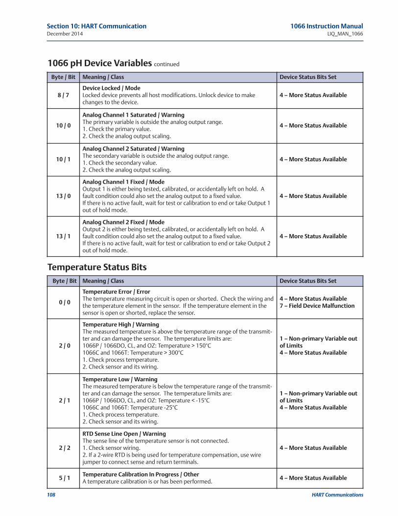
108 HART Communications
Section 10: hArT Communication 1066 Instruction ManualDecember 2014 LIQ_MAN_1066
1066 ph Device variables continued
Byte / Bit Meaning / Class Device Status Bits Set
8 / 7Device Locked / ModeLocked device prevents all host modifications. Unlock device to makechanges to the device.
4 – More Status Available
10 / 0
Analog Channel 1 Saturated / WarningThe primary variable is outside the analog output range. 1. Check the primary value.2. Check the analog output scaling.
4 – More Status Available
10 / 1
Analog Channel 2 Saturated / WarningThe secondary variable is outside the analog output range. 1. Check the secondary value.2. Check the analog output scaling.
4 – More Status Available
13 / 0
Analog Channel 1 Fixed / ModeOutput 1 is either being tested, calibrated, or accidentally left on hold. Afault condition could also set the analog output to a fixed value.If there is no active fault, wait for test or calibration to end or take Output 1out of hold mode.
4 – More Status Available
13 / 1
Analog Channel 2 Fixed / ModeOutput 2 is either being tested, calibrated, or accidentally left on hold. Afault condition could also set the analog output to a fixed value.If there is no active fault, wait for test or calibration to end or take Output 2out of hold mode.
4 – More Status Available
Byte / Bit Meaning / Class Device Status Bits Set
0 / 0
Temperature Error / ErrorThe temperature measuring circuit is open or shorted. Check the wiring andthe temperature element in the sensor. If the temperature element in thesensor is open or shorted, replace the sensor.
4 – More Status Available 7 – Field Device Malfunction
2 / 0
Temperature high / WarningThe measured temperature is above the temperature range of the transmit-ter and can damage the sensor. The temperature limits are:1066P / 1066DO, CL, and OZ: Temperature > 150°C1066C and 1066T: Temperature > 300°C1. Check process temperature.2. Check sensor and its wiring.
1 – non-primary variable outof Limits4 – More Status Available
2 / 1
Temperature Low / WarningThe measured temperature is below the temperature range of the transmit-ter and can damage the sensor. The temperature limits are:1066P / 1066DO, CL, and OZ: Temperature < -15°C1066C and 1066T: Temperature -25°C1. Check process temperature.2. Check sensor and its wiring.
1 – non-primary variable outof Limits4 – More Status Available
2 / 2
rTD Sense Line open / WarningThe sense line of the temperature sensor is not connected.1. Check sensor wiring.2. If a 2-wire RTD is being used for temperature compensation, use wirejumper to connect sense and return terminals.
4 – More Status Available
5 / 1Temperature Calibration In progress / otherA temperature calibration is or has been performed.
4 – More Status Available
Temperature Status Bits

HART Communications 109
1066 Instruction Manual Section 10: hArT CommunicationLIQ_MAN_1066 December 2014
1066ph/orp Status Bits
Byte / Bit Meaning / Class Device Status Bits Set
0 / 1
reference Impedance Too high / ErrorThe reference impedance is above the high fault setpoint. The reference electrode may be coated or plugged.1. Clean or replace the sensor.2. Check sensor wiring.3. Increase the setpoint value.4. Set the reference impedance level to high.
4 – More Status Available 7 – Field Device Malfunction
0 / 2
Glass Impedance Too high / ErrorThe glass impedance is above the high fault setpoint. The glass electrodemay be severely coated.1. Clean or replace sensor. 2. Check sensor wiring.3. Increase the glass impedance high fault setpoint.
4 – More Status Available 7 – Field Device Malfunction
0 / 3
Broken ph Glass / ErrorThe glass impedance is too low. The glass electrode of the pH sensor may becracked.1. Check sensor. Replace sensor if cracks are present.2. Check sensor wiring.3. Check preamplifier location configuration.
4 – More Status Available 7 – Field Device Malfunction
2 / 3
ph voltage Too high / WarningThe sensor voltage is outside the expected range for a pH measurement.1. Check sensor wiring.2. Replace sensor.
4 – More Status Available
4 / 0
ph Slope Too high / WarningThe pH slope calculated during buffer calibration exceeded the maximumslope limit.1. Check the buffers used and retry buffer calibration.2. Increase the maximum slope limit (default is 62 mV/pH). Note: A slope of62 mV/pH or greater indicates that there has been an error made during cali-bration or a faulty pH sensor.3. Replace sensor.
4 – More Status Available
4 / 1
ph Slope Too Low / WarningThe pH slope calculated during buffer calibration was below the minimumslope limit. The pH electrode may be worn out, damaged, or coated.1. Check and clean sensor, then retry buffer calibration.2. Decrease minimum slope limit (default is 40 mV/pH). Note that a pH sen-sor with a slope less than 50 mV/pH is usually near the end of its useful life.3. Replace sensor.
4 – More Status Available
4 / 2
zero offset Error / WarningThe zero offset from a buffer calibration or single point standardization hasexceeded the limit. The reference electrode may be poisoned or plugged.1. Check and clean sensor, then retry buffer calibration.2. Increase maximum offset limit (default is 60mV). Note that a pH sensorwith an offset of 60 mV or greater is likely poisoned and has to be replaced.3. Replace sensor.
4 – More Status Available
4 / 3 Calibration Error / Warning 4 – More Status Available
5 / 4ph Standardization In progress / otherA pH standardization is being or has been performed.
4 – More Status Available
5 / 5Buffer Calibration In progress / otherA pH buffer calibration is being or has been performed.
4 – More Status Available
5 / 6Stabilization In progress / otherA pH sensor is stabilizing or has been stabilizing.
4 – More Status Available

110 HART Communications
Section 10: hArT Communication 1066 Instruction ManualDecember 2014 LIQ_MAN_1066
Byte / Bit Meaning / Class Device Status Bits Set
2 / 5
need zero Calibration / WarningThe sensor offset is too high resulting in a negative reading. This trigger point forthis alert is dependent upon the conductivity measurement technology:1066C: (conductance - zero offset) < -2µS1066T: (conductance - zero offset) < -50µSA sensor zero calibration should be performed.
4 – More Status Available
2 / 6
Concentration out of range / WarningThe measured concentration is outside the conductivity range where a valid con-centration can be derived for the following 5 concentrations:0 to 20% NaCl0 to 12% NaOH0 to 15% HCl0 to 25% H2SO496 to 99.7% H2SO4. If there are no other fault conditions check process temperature and check thatthe actual concentration is outside the range for which curve is defined.
4 – More Status Available
2 / 7
Input out of range / WarningThe input is outside the device measurement range. the range limits are:1066C (2- electrode conductivity): Conductance > 500mS1066CT (4- electrode conductivity): (Conductance > 3000mS) or (Vcond < 0mV)1066T: Conductance > 1500mS1. Check sensor wiring.2. Replace sensor.
4 – More Status Available
4 / 3Calibration Error / WarningAn error occurred in the last calibration procedure.Check sensor and repeat the calibration procedure.
4 – More Status Available
4 / 4Sensor zero Error / WarningAn error occurred in the last sensor zero procedure.Check sensor and repeat sensor zero procedure.
4 – More Status Available
5 / 2Sensor zero In progress / otherA sensor zero is being or has been performed.
4 – More Status Available
5 / 3zero Cal In Water In progress / otherA zero calibration in water is being or has been performed.
4 – More Status Available
5 / 4Meter Calibration In progress / otherA meter calibration is being or has been performed.
4 – More Status Available
5 / 5Curve Fit In progress / otherA curve fit is being or has been performed.
4 – More Status Available
1066C and 1066T Status Bits continued

HART Communications 111
1066 Instruction Manual Section 10: hArT CommunicationLIQ_MAN_1066 December 2014
Byte / Bit Meaning / Class Device Status Bits Set
2 / 4
SEnSor_CurrEnT > 300 nA for OXYGEN BioRx - OtherSENSOR_CURRENT > 800 nA for OXYGEN BrewingSENSOR_CURRENT > 106 uA for OXYGEN Oxygen in GasSENSOR_CURRENT > 350 nA for Ozone SENSOR_CURRENT > 5 uA for Free ChlorineSENSOR_CURRENT > 40 uA for Total ChlorineSENSOR_CURRENT > 20 uA for Monochloramine
1. Make sure the device configuration matches the sensor being used.2. Check sensor wiring.3. Replace sensor.
4 – More Status Available
2 / 5
need zero Calibration / WarningThe sensor offset is too high resulting in a negative reading.The sensor zero limits are:PV < -0.5 if unit is ppm or mg/LPV < -50 if unit is ppb or ug/LPV < -2.0 % for % SaturationPV < -2.0 % for Concentration in GasPV < -20 ppm for Concentration in GasPV < -30 mmHg for Partial Pressure
Perform sensor a zero calibration.
4 – More Status Available
4 / 3Calibration Error / WarningThere has been a calibration error.Check the sensor.
4 – More Status Available
4 / 4Sensor zero Error / WarningAn error occurred in the last sensor zero procedure.Check sensor and repeat sensor zero procedure.
5 / 2Sensor zero In progress / otherA sensor zero is being or has been performed.
4 – More Status Available
5 / 3Air Cal In progress / otherAn air calibration is being or has been performed.
4 – More Status Available
5 / 6Stabilization In progress / otherThe sensor is stabilizing or has stabilized.
4 – More Status Available
1066Do, 1066CL, 1066oz Statuss Bits

112 HART Communications
Section 10: hArT Communication 1066 Instruction ManualDecember 2014 LIQ_MAN_1066
Type Enumeration / range read/Write Default
input_filter_typeSelects between continuous and adaptive filteringof the measurement.
ENUMAdaptiveContinuous
R / W Adaptive
pv_damping_valueProvides the filter time constant. FLOAT 0.0 -- 99.0 seconds R / W 0
instrument_software_versionThe software version of the main processor. FLOAT R
input_software_versionThe software version of the input processor. FLOAT R
Display parameters:
loi_languageSelects the language to be displayed by the 1066.
ENUM
English ItalianoFrançais PortuguêsEspañol ChineseDeutsch Russian
R / W English
loi_warningsEnables or disables the display of transmitter warnings. ENUM Enable
Disable R / W Enable
loi_configuration_codeLocks and unlocks access to configuration from thekeypad display of the 1066. "000" disables.
UINT (2) R / W 0
loi_calibration_codeLocks and unlocks access to calibration from thekeypad display of the 1066. "000" disables.
UINT (2) R / W 0
loi_main_display_upperSelects the measurement displayed on the upperportion of the main display.
ENUMAssign PVBlank
R / W Assign PV
loi_main_display_centerSelects the measurement displayed on the centerportion of the main display.
ENUM
Compensating pH (free Cl)TemperaturePVBlank
R / W Temperature
loi_main_display_leftSelects the measurement or output displayed onthe left portion of the display.
ENUM Valid List per 1066 Model R / W
loi_main_display_lower_leftSelects the measurement or output displayed onthe lower left portion of the display.
ENUM Valid List per 1066 Model R / W
loi_main_display_rightSelects the measurement or output displayed onthe right portion of the display.
ENUM Valid List per 1066 Model R / W
loi_main_display_lower_rightSelects the measurement or output displayed onthe lower right portion of the display.
ENUM Valid List per 1066 Model R / W
1066ph/orp:
valid ListInput mvGlass Impedanceref ImpedanceSlopezero offset
1066C/T:valid Listraw Conductivityraw resistivity
1066Do/CL/oz:valid ListInput Currentph (if free chlorine)
All 1066:
valid ListAo 1 CurrentAo 1 % outputAo 2 CurrentAo 2 % output
parameters Common to All 1066 Transmitters
AppEnDIx 10.3 – 1066 hArT Configuration parameters

HART Communications 113
1066 Instruction Manual Section 10: hArT CommunicationLIQ_MAN_1066 December 2014
Type Enumeration / range read/Write Default
rtd_offsetThe temperature offset resulting from a tempera-ture calibration.
FLOAT R / W 0
rtd_slopeThe slope (dimensionless) resulting from a twopoint temperature calibration. (Valid for cell constants < 0.02 1/cm)
FLOAT R / W 1
temp_comp_modeSelects automatic or manual temperature compensation.
ENUMManualAutomatic
R / W Automatic
manual_temperatureIf manual temperature compensation is chosen, provides a constant temperature value used by thetransmitter.
FLOAT R / W 25.0 C
1066 Temperature parameters
Type Enumeration / range read/Write Default
zero_offsetThe zero offset of a pH sensor resulting from a calibration.
FLOAT R / W 0.0 mV
ph_slopeThe slope of a pH sensor resulting from a buffer calibration.
FLOAT 40 -- 62 mV/pH R / W 59.16 mV/pH
zero_offset_limitThe maximum value of the zero offset allowed for a success-ful calibration.
FLOAT R / W 60
min_ph_slopeThe minimum value of the slope allowed for a successful calibration.
FLOAT 40 -- 62 mV/pH R / W 40 mV/pH
max_ph_slopeThe maximum value of the slope allowed for a successful calibration.
FLOAT 40 -- 62 mV/pH R / W 62 mV/pH
ph_stabilization_timeThe period of time used to determine stability of a pH sensorduring automatic calibration.
FLOAT 0 -- 99 seconds R / W 10 seconds
ph_stabilization_valueThe pH change used to determine stability of a pH sensorduring automatic calibration.
FLOAT 0.01 -- 1.0 pH R / W 0.02 pH
ph_buffer_standardThe types of pH buffers available for automatic calibration.
ENUM
Standard / NistDIN 19267
Ingold MerckFisher
R / WStandard /
Nist
preamp_locationThe location of the preamplifier in a pH measurement.
ENUManalyzer
sensor / J-boxR / W
reference_impedance_levelConfigures the transmitter to use reference electrodes withimpedances less than 500 kohm (low) or greater than 500kohm (high).
ENUMLow High
R / W Low
ph_solution_temperature_correctionConfigures the transmitter to correct the pH measurementfor changes in the pH of the solution with temperature.
ENUM
Offultra pure water
high pHammonia
custom
Off
ph_solution_temperature_coefficientThe coefficient used to correct solution pH when using cus-tom solution pH temperature correction.
FLOAT -9.999 -- 9.999 pH/deg C R / W0.000
pH/degC
1066 ph/orp

114 HART Communications
Section 10: hArT Communication 1066 Instruction ManualDecember 2014 LIQ_MAN_1066
Type Enumeration / range read/Write Default
ph_display_resolutionChanges the resolution of the displayed pH value.
ENUM0.01 pH0.1 pH
R / W 0.01 pH
ph_sensor_isopotentialThe pH at which the millivolt output of the pH sensorremains constant with temperature changes; virtually always7.00 pH.
FLOAT 0.00 -- 14.00 pH R / W 7.00 pH
refz_high_fault_setpointThe high setpoint that triggers a reference electrodeimpedance alert.
FLOAT 0.0 -- 9,999.0 kohm R / W 500.0 kohm
glassz_high_fault_setpointThe high setpoint that triggers a glass pH electrode impedance alert.
FLOAT 0.0 -- 9,999.0 Mohm R / W 1,500 Mohm
diagnostics_switchTurns the glass and reference electrode impedance measurements on and off.
ENUMOffOn
R / W Off
glassz_temperature_correctionTurns temperature correction of the glass impedance measurement on and off.
ENUMOffOn
R / W Off
glassz_measurement_typeToggles between a basic glass impedance measurement, andan advanced impedance measurement that is more accurate.
ENUMAdvanced
BasicR / W Advanced
calculated_offsetThe preliminary zero offset calculated by a pH calibrationbefore it is accepted by the transmitter.
FLOAT R / W
calculated_slopeThe preliminary slope calculated by a pH calibration before itis accepted by the transmitter.
FLOAT R / W
1066 ph/orp continued

HART Communications 115
1066 Instruction Manual Section 10: hArT CommunicationLIQ_MAN_1066 December 2014
Type Enumeration / range read/Write Default
conductivity_unitThe conductivity unit used by the measurement.
ENUMmS/cmmS/cm
R / W mS/cm
cell_constantThe cell constant of the conductivity sensor being used, typicallydetermined by calibration.
FLOAT 0.0001-- 100.0 /cm R / W 1.00 /cm
cable_correctionSelects automatic or manual cable resistance correction.
ENUMManual
AutomaticR / W Automatic
manual_cable_resistanceThe known cable resistance used in manual cable correction.
FLOAT 0.0 -- 99.99 ohm R / W 0.0 ohm
zero_offset_in_airThe zero offset determined by a zero calibration in air.
FLOAT R only 0.0 mS
zero_offset_in_solnThe zero offset determined by a zero calibration in a solution.
FLOAT R only 0.00%
custom_curve_num_data_pointsThe number of conductivity and concentration points to be usedto calculate a custom concentration curve.
ENUM
2345
R / W 3
Custom Curve Concentration Data points:
custom_curve_concentration_1 FLOAT R / W
custom_curve_concentration_2 FLOAT R / W
custom_curve_concentration_3 FLOAT R / W
custom_curve_concentration_4 FLOAT R / W
custom_curve_concentration_5 FLOAT R / W
Custom Curve Conductivity Data points:
custom_curve_conductivity_1 FLOAT R / W
custom_curve_conductivity_2 FLOAT R / W
custom_curve_conductivity_3 FLOAT R / W
custom_curve_conductivity_4 FLOAT R / W
custom_curve_conductivity_5 FLOAT R / W
1066C and 1066T

116 HART Communications
Section 10: hArT Communication 1066 Instruction ManualDecember 2014 LIQ_MAN_1066
Type Enumeration / range read/Write Default
toroidal_sensor_modelSelects the model of toroidal sensor being used forenhanced accuracy.
ENUM
228225226247Other
R / W 228
cond_rangeSelects a particular range for the conductivitymeasurement or automatic ranging for toroidalsensors.
ENUM
Automatic50-600mS0.5-100mS90-1500mS
R / W Automatic
temp_comp_typeThe type of temperature compensation used bythe transmitter.
ENUMLinear slopeRaw / None
R / W Linear slope
temp_comp_slopeProvides a slope value used in linear temperaturecompensation.
FLOAT R / W 2.0 %/degree C
reference_temperatureThe temperature that temperature compensationcorrects to. It is usually 25 C.
FLOAT R / W 25.0 C
Type Enumeration / range read/Write Default
electrode_typeType of contacting conductivity sensor being usedby the transmitter.
ENUM2-Electrode4-Electrode
R / W 2-Electrode
cond_rangeSelects a particular range for the conductivitymeasurement or automatic ranging for 2 and 4electrode sensors.
ENUM R / W Automatic
2-Electrode:
Automatic0-50mS40-500mS400-2000mS1.8-20mS18-200mS
4-Electrode:
Automatic0-42mS/cm36-200mS/cm180-1000mS/cm0.9-10mS/cm9-600mS/cm
series_cap_correctionTurns capacitance correction on and off.
ENUMOffOn
R / W Off
cell_factorThe second calibration constant used by a 4 electrode sensor in addition to cell constant.
FLOAT R / W 0.95 /cm
temp_comp_typeThe type of temperature compensation used bythe transmitter.
ENUM
Linear slopeNeutral saltCationRaw / None
R / W Linear slope
temp_comp_slopeProvides a slope value used in linear temperaturecompensation.
FLOAT 0.2 -- 9.99 %/degreec C R / W2.0 %/degree
C
reference_temperatureThe temperature that temperature compensationcorrects to. It is usually 25 C.
FLOAT R / W 25.0 C
1066C
1066T

HART Communications 117
Type Enumeration / range read/Write Default
polar_voltageThe polarization voltage used by the transmitter;automatically set by sensor selection.
FLOAT R / W 0
temp_coeffThe temperature coefficient used to compensatetemperature; automatically set by sensor selection.
FLOAT R / W 0
amp_sensor_sensitivityThe response of the sensor to changes in concentra-tion, determined by calibration.
FLOAT 0.1 -- 1,000,000.0 nA/ppm R / W 2,500 nA/ppm
amp_sensor_zero_currentThe current output of the sensor when the concen-tration is 0. It is determined by a zero calibration.
FLOAT -999.9 -- 999.9 nA R / W 0.0 nA
1066oz/CL/Do
Type Enumeration / range read/Write Default
ozone_resolutionThe resolution of the displayed ozone measurement.
ENUM0.0010.01
R / W 0.001
1066 Instruction Manual Section 10: hArT CommunicationLIQ_MAN_1066 December 2014
Type Enumeration / range read/Write Default
chlorine_typeThe type of chlorine being measured.
ENUMFree ChlorineTotal Chlorine
ChloramineR / W Free Chlorine
chlorine_resolutionThe resolution of the displayed chlorine measurement.
ENUM0.001 ppm0.01 ppm
R / W 0.001 ppm
ph_correction_mode Turns automatic pH compensation of free chlorine measure-ments on and off.
ENUMOnOff
R / W Off
manual_phProvides a constant pH value, if manual pH compensation of afree chlorine measurement is used.
FLOAT 0.00 -- 14.00 pH R / W 7.00 pH
1066oz
1066CL

118 HART Communications
Type Enumeration / range read/Write Default
oxygen_sensor_typeThe type of oxygen sensor used.
ENUM
Water/WasteTrace OxygenBioRx-RosemountBioRx-OtherBrewingOxygen In Gas
R / W Water/Waste
oxygen_measurement_typeThe type of oxygen measurement being made.
ENUM
Concentration in LiquidPercent SaturationPartial PressureConcentration in Gas
R / WConcentratio
n in Liquid
oxygen_salinityThe salinity of the process solution, which is usedby the transmitter to correct for the effect of salini-ty on the oxygen measurement.
FLOAT 0.0 - 99.9 ppth R / W 0.0 ppth
pressure_unitsThe units of pressure used by the oxygen measure-ment.
ENUM
mmHginHgpsiatmkPambarbar
R / W mmHg
oxygen_process_pressureThe process pressure used by the transmitter tocalculate percent oxygen in gas or % saturation.
FLOAT R / W 760.0 mmHg
oxygen_air_pressureThe barometric pressure used by the transmitterduring an air calibration.
FLOAT R / W 760.0 mmHg
oxygen_unitsThe available units used for the various oxygenmeasurement types.
ENUM R / W
Concentration inLiquid:
units:ppmppbmg/Lmg/L
ppm
percentSaturation
units:%
%
partial pressure
units:mmhg kpainhg mbarpsi baratm
mmHg
oxygen In Gasunits:ppm%
%
air_cal_stabilization_timeThe period of time used to determine stability of anoxygen sensor during an air calibration.
FLOAT 0 -- 99 seconds R / W 10 seconds
air_cal_stabilization_valueThe change in the oxygen measurement used todetermine stability of an oxygen sensor during anair calibration.
FLOAT 0.001 -- 9,999.0 R / W 0.05
air_cal_stabilization_value_unitThe unit used during an air calibration.
FLOAT R / W ppm
Section 10: hArT Communication 1066 Instruction ManualDecember 2014 LIQ_MAN_1066
1066Do

HART Communications 119
1066 Instruction Manual Section 10: hArT CommunicationLIQ_MAN_1066 December 2014
1. overview1.1. Device Status1.2. Comm Status1.3. PV1.4. SV1.5. Loop Current1.6. % of Range1.7. Find Device1.8. Device Information
1.8.1. Identification1.8.1.1. Tag1.8.1.2. Long Tag1.8.1.3. Model1.8.1.4. Serial Number1.8.1.5. Date1.8.1.6. Descriptor1.8.1.7. Message
1.8.2. Revision Numbers1.8.2.1. Universal1.8.2.2. Field Device1.8.2.3. DD Revision1.8.2.4. Hardware1.8.2.5. Instrument Software1.8.2.6. Input Software
2. Configure2.1. Guided Setup
2.1.1. Basic Setup2.2. Manual Setup
2.2.1. Device Information2.2.1.1. Tag2.2.1.2. Long Tag2.2.1.3. Descriptor2.2.1.4. Message2.2.1.5. Date2.2.1.6. Current Date2.2.1.7. Current Time2.2.1.8. Set Date and Time
2.2.2. Measurement (1066 ph/orp)2.2.2.1. PV is2.2.2.2. Preamp Location2.2.2.3. Soln Temp Correct’n (pH only)2.2.2.4. Temp Coefficient (PV is pH and Soln Temp Correct’n is Custom)2.2.2.5. Resolution (pH only)2.2.2.6. Sensor Isopotential (pH only)2.2.2.7. Input Filter2.2.2.8. Filter Type2.2.2.9. Reference Imp
2.2.3. Measurement (1066 Do)2.2.3.1. Sensor Type2.2.3.2. Measurement Type2.2.3.3. PV Unit2.2.3.4. Salinity2.2.3.5. Pressure Unit2.2.3.6. Input Filter2.2.3.7. Filter Type2.2.3.8. Polar Voltage2.2.3.9. Temp Coefficient
AppEnDIx 10.4 – 475 Menu Tree for 1066 hArT 7

120 HART Communications
2.2.4. Measurement (1066 oz)2.2.4.1. PV Unit2.2.4.2. Resolution2.2.4.3. Input Filter2.2.4.4. Filter Type2.2.4.5. Polar Voltage2.2.4.6. Temp Coefficient
2.2.5. Measurement (1066 CL)2.2.5.1. Measurement Type2.2.5.2. PV Unit2.2.5.3. Resolution2.2.5.4. pH Correction (Free Chlorine Measurement Type only)
2.2.5.4.1. pH CorrectionIf pH Correction is manual
2.2.5.4.2. Manual pHIf pH Correction is Live/Continuous
2.2.5.4.3. Preamp Location2.2.5.4.4. Resolution2.2.5.4.5. Sensor Isopotential2.2.5.4.6. Soln Temp Correct’n
2.2.5.5. Input Filter2.2.5.6. Filter Type2.2.5.7. Polar Voltage2.2.5.8. Temp Coefficient
2.2.6. Measurement (1066 C and 1066 T)2.2.6.1. Measurement Type2.2.6.2. PV Unit2.2.6.3. Sensor Config
2.2.6.3.1. Sensor Type (Contacting Model)2.2.6.3.2. Sensor Model (Toroidal Model)2.2.6.3.3. Range2.2.6.3.4. Cell Constant2.2.6.3.5. Cell Factor (4-Electrode)2.2.6.3.6. RTD Offset (Cell Constant < 0.02)2.2.6.3.7. RTD Slope (Cell Constant < 0.02)
2.2.6.4. Setup Custom Curve (Custom Curve Measurement)2.2.6.5. Temp Comp
2.2.6.5.1. Temp Comp Type2.2.6.5.2. Temp Slope2.2.6.5.3. Reference Temp
2.2.6.6. Cable Correction (2-Electrode or Toroidal)2.2.6.6.1. Series Cap Corr2.2.6.6.2. Cable R. Correction 2.2.6.6.3. Cable Resistance
2.2.6.7. Input Filter2.2.6.8. Filter Type
2.2.7. Temperature2.2.7.1. Temperature Unit2.2.7.2. Temp Comp2.2.7.3. Manual Value (If Temp Comp is Manual)
2.2.8. Analog outputs2.2.8.1. Output 1
2.2.8.1.1. Primary Variable2.2.8.1.2. PV URV2.2.8.1.3. PV LRV2.2.8.1.4. Scale2.2.8.1.5. Dampening2.2.8.1.6. Fault Mode2.2.8.1.7. Fault Value
Section 10: hArT Communication 1066 Instruction ManualDecember 2014 LIQ_MAN_1066

HART Communications 121
1066 Instruction Manual Section 10: hArT CommunicationLIQ_MAN_1066 December 2014
2.2.8.2. Output 22.2.8.2.1. Secondary Variable2.2.8.2.2. SV URV2.2.8.2.3. SV LRV2.2.8.2.4. Scale2.2.8.2.5. Dampening2.2.8.2.6. Fault Mode2.2.8.2.7. Fault Value
2.2.9. Communications2.2.9.1. Burst Message 1
2.2.9.1.1. Burst Message2.2.9.1.2. Message Content2.2.9.1.3. Update Rate
2.2.9.1.3.1. Trigger Mode2.2.9.1.3.2. Trigger Level2.2.9.1.3.3. Trigger Level Unit2.2.9.1.3.4. Classification2.2.9.1.3.5. Update Rate2.2.9.1.3.6. Default Update Rate
2.2.9.2. Burst Message 22.2.9.2.1. Burst Message2.2.9.2.2. Message Content2.2.9.2.3. Update Rate
2.2.9.2.3.1. Trigger Mode2.2.9.2.3.2. Trigger Level2.2.9.2.3.3. Trigger Level Unit2.2.9.2.3.4. Classification2.2.9.2.3.5. Update Rate2.2.9.2.3.6. Default Update Rate
2.2.9.3. Burst Message 32.2.9.3.1. Burst Message2.2.9.3.2. Message Content2.2.9.3.3. Update Rate
2.2.9.3.3.1. Trigger Mode2.2.9.3.3.2. Trigger Level2.2.9.3.3.3. Trigger Level Unit2.2.9.3.3.4. Classification2.2.9.3.3.5. Update Rate2.2.9.3.3.6. Default Update Rate
2.2.9.4. Event Notification2.2.9.4.1. Event Message2.2.9.4.2. Unack Update Rate2.2.9.4.3. Default Update Rate2.2.9.4.4. Debounce Interval2.2.9.4.5. Pending Events2.2.9.4.6. Acknowledge Event (If there are pending events)
2.2.9.5. 12-Point Sample2.2.9.5.1. Data Sampling2.2.9.5.2. Device Variable2.2.9.5.3. Sample Interval2.2.9.5.4. 12-Point Sample (Data Sampling is not Off)
2.2.9.6. Variable Mapping2.2.9.6.1. PV is2.2.9.6.2. SV is2.2.9.6.3. TV is2.2.9.6.4. QV is
2.2.9.7. Multidrop2.2.9.7.1. Polling Address2.2.9.7.2. Loop Current Mode

122 HART Communications
2.2.10. Device Display2.2.10.1. Main Display Format
2.2.10.1.1. Upper2.2.10.1.2. Center2.2.10.1.3. Left2.2.10.1.4. Lower Left2.2.10.1.5. Right2.2.10.1.6. Lower Right
2.2.10.2. Display Language2.2.10.3. Warnings2.2.10.4. Display Contrast
2.2.11.Security2.2.11.1. HART Lock
2.2.11.1.1. Lock State2.2.11.1.2. Lock/Unlock
2.2.11.2. Local Operator Interface2.2.11.2.1. Configuration Code2.2.11.2.2. Calibration Code
2.3. Alert Setup2.3.1. Diagnostics (1066 ph/orp/redox only)
2.3.1.1. Reference Imp2.3.1.1.1. High Fault Setpoint
2.3.1.2. Glass Impedance (pH only)2.3.1.2.1. High Fault Setpoint2.3.1.2.2. Temp Correction2.3.1.2.3. Measurement Type
3. Service Tools3.1. Alerts3.2. Variables3.3. Trends3.4. Maintenance
3.4.1. 1066 Do (1066 Do only)3.4.1.1. Oxygen3.4.1.2. Temperature3.4.1.3. Input Current3.4.1.4. Air Calibration3.4.1.5. Air Calibration Setup3.4.1.6. Zero Calibration3.4.1.7. In-Process Cal3.4.1.8. [email protected]. Zero Current
3.4.2. 1066 CL /1066 oz (1066 CL /1066 oz only)3.4.2.1. Chlorine/Ozone3.4.2.2. Temperature3.4.2.3. Input Current3.4.2.4. Zero Calibration3.4.2.5. In-Process Cal3.4.2.6. [email protected]. Zero Current
Section 10: hArT Communication 1066 Instruction ManualDecember 2014 LIQ_MAN_1066

HART Communications 123
1066 Instruction Manual Section 10: hArT CommunicationLIQ_MAN_1066 December 2014
3.4.3. 1066 ph/orp (ph only)3.4.3.1. pH3.4.3.2. pH Buffer Calibration3.4.3.3. Standardize pH3.4.3.4. pH Slope3.4.3.5. Zero Offset3.4.3.6. Calibration Setup
3.4.3.6.1. Limits3.4.3.6.1.1. Minimum Slope3.4.3.6.1.2. Maximum Slope3.4.3.6.1.3. Maximum Offset
3.4.3.6.2. Automatic Buffer Recognition3.4.3.6.2.1. Buffer Standard3.4.3.6.2.2. Stable Time3.4.3.6.2.3. Stable Delta
3.4.4. 1066 ph/orp (orp/redox only)3.4.4.1. ORP/Redox3.4.4.2. Calibrate ORP/Redox3.4.4.3. Zero Offset3.4.4.4. Maximum Offset
3.4.5. 1066 C/1066 T (1066 C/1066 T only)3.4.5.1. Conductivity3.4.5.2. Raw Conductivity3.4.5.3. Temperature3.4.5.4. Zero Calibration3.4.5.5. In-Process Calibration3.4.5.6. Cell Constant3.4.5.7. Cell Factor (4 electrode)3.4.5.8. Zero Offset3.4.5.9. Soln Offset (%Concentration)
3.4.6. Temperature3.4.6.1. Temperature3.4.6.2. Calibrate Temp3.4.6.3. RTD Offset
3.4.7. Analog outputs3.4.7.1. Output 1
3.4.7.1.1. Loop Current3.4.7.1.2. Calibrate Output 1
3.4.7.2. Output 23.4.7.2.1. SV Current3.4.7.2.2. Calibrate Output 2
3.4.8. Meter3.4.8.1. Input Resistance3.4.8.2. Meter Calibration
3.4.9. reset/restore3.4.9.1. Reset Device3.4.9.2. Load Default Configuration3.4.9.3. Reset Configuration Changed
3.5. Simulate3.5.1. PV (show current PV type label)3.5.2. Temperature3.5.3. End Variable Simulation (If any variable is being simulated)3.5.4. Output 13.5.5. Output 2

124 HART Communications
Section 10: hArT Communication 1066 Instruction ManualDecember 2014 LIQ_MAN_1066
This page left intentionally blank

Return of Materials 125
1066 Instruction Manual Section 11: return of MaterialLIQ_MAN_1066 December 2014
General
To expedite the repair and return of instruments, proper communication between the customer
and the factory is important. Before returning a product for repair, call 1-949-757-8500 for a
Return Materials Authorization (RMA) number.
Warranty repair
The following is the procedure for returning instruments still under warranty:
1. Call Rosemount Analytical for authorization.
2. To verify warranty, supply the factory sales order number or the original purchase order
number. In the case of individual parts or sub-assemblies, the serial number on the unit must
be supplied.
3. Carefully package the materials and enclose your “Letter of Transmittal” (see Warranty). If
possible, pack the materials in the same manner as they were received.
4. Send the package prepaid to:
Rosemount Analytical
2400 Barranca Parkway
Irvine, CA 92606
Attn: Factory Repair
RMA No. ____________
Mark the package: Returned for Repair
Model No. ___________
non-Warranty repair
The following is the procedure for returning for repair instruments that are no longer under warranty:
1. Call Rosemount Analytical for authorization.
2. Supply the purchase order number, and make sure to provide the name and telephone num-
ber of the individual to be contacted should additional information be needed.
3. Do Steps 3 and 4 of Section 10.2.
11.1
11.2
11.3
Section 11: Return of Material
noTE
Consult the factory for additional information regarding service or repair.
IMporTAnT
please see second section of “return of
Materials request” form. Compliance with
the oShA requirements is mandatory for
the safety of all personnel. MSDS forms and
a certification that the instruments have
been disinfected or detoxified are required.

EC Declaration of Conformity 1066 Instruction ManualDecember 2014 LIQ_MAN_1066
126 EC Declaration of Conformity

1066 Instruction Manual EC Declaration of ConformityLIQ_MAN_1066 December 2014
EC Declaration of Conformity 127

128
EC Declaration of Conformity 1066 Instruction ManualDecember 2014 LIQ_MAN_1066
This page left intentionally blank

129
1066 Instruction Manual EC Declaration of ConformityLIQ_MAN_1066 December 2014
This page left intentionally blank

Credit Cards for U.S. Purchases Only.
8
Emerson process Management
2400 Barranca Parkway
Irvine, CA 92606 USA
Tel: (949) 757-8500
Fax: (949) 474-7250
rosemountanalytical.com
© Rosemount Analytical Inc. 2013
©2013 Rosemount Analytical, Inc. All rights reserved.
The Emerson logo is a trademark and service mark of Emerson Electric Co. Brand name is a markof one of the Emerson Process Management family of companies. All other marks are the propertyof their respective owners.
The contents of this publication are presented for information purposes only, and while effort hasbeen made to ensure their accuracy, they are not to be construed as warranties or guarantees,express or implied, regarding the products or services described herein or their use or applicability.All sales are governed by our terms and conditions, which are available on request. We reserve theright to modify or improve the designs or specifications of our products at any time without notice.
facebook.com/EmersonRosemountAnalytical
AnalyticExpert.com
twitter.com/RAIhome
youtube.com/user/RosemountAnalytical
LIQ_MAN_1066Rev. G
December 2014
Top Related