


Languages
Pages
Legal


Facultad de Ciencias Astronomicas y Geofısicas, UNLP, Argentina.Instituto de Astrofısica de La Plata, UNLP–CONICET, Argentina.
La PlataVariational Indicators code
A program to compute a suite ofvariational chaos indicators
User’s Guide
for Version 1.0.2 (Kaos)
AuthorsD. D. Carpintero, N. P. Maffione, L. A. Darriba
Last update: December 2013

II

Contents
1 The LP-VIcode project 11.1 Motivation . . . . . . . . . . . . . . . . . . . . . . . . . . . . . . . . . . . . . 11.2 Brief description of the LP-VIcode . . . . . . . . . . . . . . . . . . . . . . . . 11.3 Future versions . . . . . . . . . . . . . . . . . . . . . . . . . . . . . . . . . . . 2
2 Basics of LP-VIcode 32.1 Getting started . . . . . . . . . . . . . . . . . . . . . . . . . . . . . . . . . . . 32.2 INPUT data . . . . . . . . . . . . . . . . . . . . . . . . . . . . . . . . . . . . 42.3 OUTPUT data . . . . . . . . . . . . . . . . . . . . . . . . . . . . . . . . . . . 10
2.3.1 Strategy for runtime errors . . . . . . . . . . . . . . . . . . . . . . . . 10
3 Frequently asked questions 13
Acknowledgements 14
Bibliography 17
A Sample test potentials 19A.1 The 2D Henon–Heiles potential . . . . . . . . . . . . . . . . . . . . . . . . . . 19A.2 The triaxial NFW profile . . . . . . . . . . . . . . . . . . . . . . . . . . . . . 24
III
Chapter 1
The LP-VIcode project
1.1 Motivation
The correct analysis of a given dynamical system rests on the reliable identification of thechaotic or regular behaviour of its orbits. The most commonly used tools for such analysesare based either on the study of the fundamental frequencies of the trajectories, or on thestudy of the evolution of the deviation vectors, the so–called variational chaos indicators (CIshereafter). Therefore, it seems very useful to have a tool with which one can compute severalCIs in an easy and fast way. This is the main motivation of the LP-VIcode (the acronym forLa Plata–Variational Indicators code).
The alpha version of the code was first introduced in [6]. The last stable version of the codeis version 1.0.2, codename: Kaos.
1.2 Brief description of the LP-VIcode
The LP-VIcode is a program to compute a suite of CIs.
The library of CIs in the present version include the following: a) the Lyapunov Indicators,also known as Lyapunov Characteristic Exponents, Lyapunov Characteristic Numbers or Fi-nite Time Lyapunov Characteristic Numbers (LIs, [1, 2]); b) the Mean Exponential Growthfactor of Nearby Orbits (MEGNO, [3, 4]); c) the Slope Estimation of the largest LyapunovCharacteristic Exponent (SElLCE, [4]); d) the Smaller ALignment Index (SALI, [15]); e) theGeneralized ALignment Index (GALI, [16, 17]); f) the Fast Lyapunov Indicator (FLI, [9, 10]);g) the Orthogonal Fast Lyapunov Indicator (OFLI, [8]); h) the Spectral Distance (SD, [19]);i) the dynamical Spectra of Stretching Numbers (SSNs, [18, 5]); and j) the Relative LyapunovIndicator (RLI, [13, 14])1. The main achievement of the code is its speed: neither the orbitnor any of the sets of variational equations are computed more than once in each time step,even when they may be requested by more than one CI.
1A minimal package of well behaved CIs (called CIsF for Chaos Indicators Function) for analysing a generalHamiltonian system is studied in [11, 7, 12].
1

2 CHAPTER 1. THE LP-VICODE PROJECT
The program is written in standard Fortran772, except for the common nonstandard ex-tensions DO-ENDDO, INCLUDE, DOWHILE, lowercase characters, inline comments, names longerthan 6 characters, and names containing the nonstandard character “ ”. All real variablesare DOUBLE PRECISION.
The program reads initial conditions (hereafter i.c.) for one or more orbits, and integratesthem, computing at the same time the set of CIs chosen by the user. The integrator is aBulirsch–Stoer routine.
1.3 Future versions
The main goal of the LP-VIcode project is to cluster in a single, easy-to-use tool the plethoraof CIs that are nowadays in the literature. The starting point is the present LP-VIcode code.We intend to motivate researchers to collaborate with their own methods in developing newerversions of the code with larger CIs’ libraries.
Also, we are open to people who might be interested in making the code more user friendly.For example, changing the present command–driven interface to a menu–driven interface, etc.
2There is also a version written in Fortran90 for parallel computing, though in a developing stage.

Chapter 2
Basics of LP-VIcode
2.1 Getting started
In order to use LP-VIcode the user needs:
1. a text editor to edit the files: *.pav, LP-VIcode.in and LP-VIcode.par;
2. a Fortran compiler to compile and execute the source Fortran code: LP-VIcode.for
and LP-VIcode.par.
The main files of LP-VIcode (LP-VIcode.for, which is fully commented for easier understand-ing, and its companion LP-VIcode.par), an input data file (LP-VIcode.in), files defining the2D Henon–Heiles model, the 2D logarithmic potential and a triaxial NFW profile [20] assample test potentials (henon-heiles.pav, logarithmic2.pav, nfwtriaxial.pav, respec-tively) and examples of input files of i.c. for each potential (in-hh.dat, in-log.dat andin-nfwtriaxial.dat, respectively)1, can be found at the url:
http://www.fcaglp.unlp.edu.ar/LP-VIcode/
After giving all the input data (see Section 2.2), the user should compile the LP-VIcode.for
program. For a Unix-based system, this typically requires a command like
mymachine> gfortran -o LP-VIcode LP-VIcode.for
which yields an executable file named LP-VIcode. To run this executable, the user typicallytypes
mymachine> ./LP-VIcode
In order to show how to use LP-VIcode we will apply below the code to a simple 2–dimensionallogarithmic potential (hereafter 2dLP), describing every step. Text referring to this particularexample will be written in violet.
1In Appendix A.2 we apply LP-VIcode to the 2D Henon–Heiles potential and the triaxial NFW profile usingthe abovementioned input files.
3

4 CHAPTER 2. BASICS OF LP-VICODE
2.2 INPUT data
I) The user must provide the potential in which the orbits have to be integrated, by meansof a file written in Fortran77 with the file extension: .pav (for the 2dLP, we named thefile logarithmic2.pav). This .pav file has to be included at the end of LP-VIcode.for andshould contain the following:
1. A BLOCK DATA procedure, in which the dimension and the parameters of the potentialare initialized. The COMMON /dimpot/ containing the dimension of the potential shouldbear that name. The 2dLP has dimension 2, then DATA dim/2/. Also included arethe associated parameters q and rc that describes the flattening and the core radius,respectively, and the normalization constant v02.
BLOCK DATA in logarithmic2.pav
*************************************************************
BLOCK DATA
* Logarithmic 2D potential
* Parameters: q: flattening (ratio of semiaxes)
* rc: core radius
* v02: normalization constant
*************************************************************
INTEGER dim
COMMON /dimpot/dim
DATA dim/2/
DOUBLE PRECISION q,rc,v02
COMMON /param/q,rc,v02
DATA q/0.7d0/
DATA rc/0d0/
DATA v02/1d0/
END
2. A FUNCTION potencial, in which the potential is computed from the time and thecoordinates of the phase space. For the 2dLP, the potential Φ is:
Φ(x, y) =1
2v20 ln
[x2 +
(y
q
)2
+ r2c
].
FUNCTION potencial in logarithmic2.pav
*************************************************************
FUNCTION potencial(t,x,n)
INTEGER n
DOUBLE PRECISION potencial,t,x(n)
* t = time

2.2. INPUT DATA 5
* x(n) = coordinates of the phase space
* n = dimension of the phase space
*************************************************************
DOUBLE PRECISION q,rc,v02
COMMON /param/q,rc,v02
DOUBLE PRECISION arg
arg=x(1)**2+(x(2)/q)**2+rc**2
IF(arg.GT.0d0)THEN
potencial=0.5d0*v02*LOG(arg)
ELSE
potencial=-1d38
ENDIF
END
3. A SUBROUTINE acelera, in which the accelerations (x and y) are computed from thesame data as the potential above. For the 2dLP, the accelerations are:
x = −∂Φ∂x
= − v20x2 + y2/q2 + r2c
x ;
y = −∂Φ∂y
= − v20x2 + y2/q2 + r2c
y
q2.
SUBROUTINE acelera in logarithmic2.pav
*************************************************************
SUBROUTINE acelera(t,x,n,acc)
INTEGER n
DOUBLE PRECISION t,x(n),acc(n/2)
* t = time
* x(n) = coordinates of the phase space
* n = dimension of the phase space
* acc(n/2) = accelerations (acc(1) = d[vx]/dt, etc)
*************************************************************
DOUBLE PRECISION q,rc,v02
COMMON /param/q,rc,v02
DOUBLE PRECISION aux
aux=v02/(x(1)**2+(x(2)/q)**2+rc**2)
acc(1)=-x(1)*aux
acc(2)=-x(2)*aux/q**2
END

6 CHAPTER 2. BASICS OF LP-VICODE
4. A SUBROUTINE variac, in which the variational equations corresponding to the veloci-ties (only) are computed from the same data as the potential above, plus the deltas ofthe phase space. The variational equations corresponding to the velocities for the 2dLPare:
( ˙δx) =[− v20
x2+y2/q2+r2c+
2v20x2
(x2+y2/q2+r2c )2
]δx+
[2v20xy/q
2
(x2+y2/q2+r2c )2
]δy ;
( ˙δy) =[
2v20xy/q2
(x2+y2/q2+r2c )2
]δx+
[− v20/q
2
x2+y2/q2+r2c+
2v20y2/q4
(x2+y2/q2+r2c )2
]δy .
SURBOUTINE variac in logarithmic2.pav
*************************************************************
SUBROUTINE variac(t,x,dx,n,dax)
INTEGER n
DOUBLE PRECISION t,x(n),dx(n),dax(n/2)
* t = time
* x(n) = coordinates of the phase space
* dx(n) = differentials (deltas) of the coordinates of the phase space
* n = dimension of the phase space
* dax(n/2) = derivatives (dax(1) = d[dvx]/dt, etc)
*************************************************************
DOUBLE PRECISION q,rc,v02
COMMON /param/q,rc,v02
LOGICAL prim
DOUBLE PRECISION arg,par,q2,rc2,arg2,aux1,aux2
SAVE prim,q2,rc2
DATA prim/.TRUE./
IF(prim)THEN
prim=.FALSE.
q2=q**2
rc2=rc**2
ENDIF
arg=x(1)**2+x(2)**2/q2+rc2
arg2=arg**2
par=x(1)*dx(1)+x(2)*dx(2)/q2
aux1=2d0*v02*par/arg2
aux2=v02/arg
dax(1)= aux1*x(1)-aux2*dx(1)
dax(2)=(aux1*x(2)-aux2*dx(2))/q2
END
Once the file with these routines is ready, its name should be INCLUDE’d at the end of the fileLP-VIcode.for, replacing any other *.pav file which happens to be mentioned there.

2.2. INPUT DATA 7
II) The user must also provide the input parameters requested in the file LP-VIcode.in.These data are, one per record of the file LP-VIcode.in:
1. The name of the input file where the i.c. of the orbits are to be found. In this lastfile, if the potential is of dimension n, the i.c. are given as n coordinates plus n ve-locities, in that order, one orbit per record. For example, suppose the i.c. for ourexample potential 2dLP are to be written in the file in-log.dat. The initial condition(x, y, x, y) = (0.2, 0.34, 0.5, 0.1235) should be written in that file in the following way(or any other equivalent legal Fortran77 way):
in-log.dat
0.2d0 0.34d0 0.5d0 0.1235d0
2. Prefix of the output files. The output is dumped in files with this prefix (in the case ofthe 2dLP, we chose the prefix log) appended with the following suffixes:
• .ene for the energy conservation after the integration;
• .orb for the orbit;
• .lyap for the LIs;
• .sali for the SALI;
• .gali for the GALIs;
• .sd for the SD;
• .ssn for the SSNs used to compute the SD;
• .rli for the RLI and the maximal LI computed as the rate of separation of twoinfinitesimally separated orbits;
• .megno for the MEGNO and the SElLCE;
• .fli for the FLI and the OFLI;
If there are more than one orbit to integrate, they are separated in these files with blanklines.
3. Step of integration for the orbit and the variational equations.
4. Time of integration for the orbit (the variational equations may end sooner than this ifthe corresponding indicator saturates2).
First part of LP-VIcode.in (example for the logarithmic potential)
# Initial conditions file (max. 50 characters)
in-log.dat
# Prefix for output files (max. 50 characters)
log
2The CIs that have a threshold value, and therefore may saturate, are the following: SALI, GALIs, MEGNO,FLI and OFLI.

8 CHAPTER 2. BASICS OF LP-VICODE
# Step of integration
0.05d0
# Time of integration
25000.d0
The user may also wish to integrate each orbit of an ensemble until different final times.To this end, he/she must set the time of integration to zero in the file LP-VIcode.in;this value tells the code to look after the times of integration in the input file, after theinitial conditions of each orbit. In the case of our example, the file in-log.dat shouldbe:
in-log.dat
0.2d0 0.34d0 0.5d0 0.1235d0 25000.d0
5. Screen and orbit flags. The first flag (one digit) controls whether the progress of thecomputation, as well as the energy conservation at the end of the integration of eachorbit (DE), should be output to screen (flag = 1) or not (flag = 0). The second onecontrols whether the orbit(s) should be output to a file (flag = 1) or not (flag = 0).
Example of screen output
Orbit # 1 10% 20% 30% 40% 50% 60% 70% 80% 90% DE = 4.12E-14
Orbit # 2 10% 20% 30% 40% 50% 60% 70% 80% 90% DE = 1.71E-13
Orbit # 3 10% 20% 30% 40% 50%
6. CIs flag vector. A flag 7–vector is used to control whether to compute/output the CIs,in this order: LIs, SALI, GALIs, SD & SSNs, RLI & LImax, MEGNO & SElLCE, FLI& OFLI. Each flag may take one of the following values:
• 0 = do not compute the corresponding CI, therefore also do not output;
• 1 = compute the CI, and output along the integration for the whole integrationinterval or until the CI saturates;
• 2 = compute and output only the final values. If this option is chosen, the finaltime (which corresponds to the saturation time if the CI saturated) and the initialconditions are also output to the file.
For the 2dLP we are interested in computing the time evolution of all the CIs, dumpingthe values of the orbit in a file, and watching the progress of the computation. Then,all 9 flags are set to 1 in LP-VIcode.in.
7. Number of steps between outputs: in case any of the abovementioned components of theflag 7–vector, or the flag associated with the orbit, is set to 1, this parameter indicateshow many steps have to be integrated before an output is dumped to the files.
8. Initial deviation vectors: an integer indicates whether the initial deviation vectors shouldbe generated at random ( = 0), or should be generated at random and also be orthonor-malized ( = 1) or their values are to be provided by the user ( = 2). In this last

2.2. INPUT DATA 9
case, the user should edit subroutine condini in the source file LP-VIcode.for andwrite down there 2n deviation vectors of 2n components each (being n the dimensionof the potential). The source text provides more detailed instructions. In the case ofthe 2dLP we chose random orthonormal initial deviation vectors, so we set this flag to 1.
Second part of LP-VIcode.in (example for the logarithmic potential)
# Screen (0=no, 1=yes) & orbit (0=no output, 1=dump to file)
1 1
# Indicators: 0=don’t compute, 1=output for all t, 2=output only last value
# LIs, SALI, GALIs, SD & SSNs, RLI & LImax, MEGNO & SElLCE, FLI & OFLI
1 1 1 1 1 1 1
# Nr. of steps between outputs (when indicators are = 1)
20
# Initial dev. vectors (0 = at random, 1 = random orthonormal, 2=fixed)
1
III) Fixed parameters of the program, file LP-VIcode.par:
In this file there is the parameter ndim that should be set to the dimension of the potentialbeing used. This parameter is used to define the dimension of many arrays, and is checkedagainst the dimension of the potential declared in the corresponding file .pav to avoid for-getting to change it when the potential is changed to another one with another dimension. Ifthis happens, the following error message appears: ’Dim of potential in *.pav <> dim
in LP-VIcode.par’.
The rest of the parameters of this file are not meant to be changed, but they certainly maybe modified if the user wishes. They are all described in the file LP-VIcode.par itself.
LP-VIcode.par
************************************************************************
* LP-VIcode.par: parameters of LP-VIcode.for (Version 1.0)
************************************************************************
* ndim: dimension of the potential.
INTEGER ndim
PARAMETER (ndim=2)
************************************************************************
* Dimension of the phase space
INTEGER ndimf
PARAMETER (ndimf=2*ndim)
* Maximum nr. of steps to be integrated
INTEGER npmax
PARAMETER (npmax=1000000)
* Nr. of indicators of chaos
INTEGER nind

10 CHAPTER 2. BASICS OF LP-VICODE
PARAMETER (nind=7)
* Initial separation of orbits (RLI)
DOUBLE PRECISION rlieps
PARAMETER (rlieps=1d-12)
* Number of slots in the histogram (spectral distance)
INTEGER nbin
PARAMETER (nbin=500)
* Format for the output of numbers
CHARACTER fo*11
PARAMETER (fo=’(e22.16,1x)’)
* Saturation values of the indicators:
* SALI, GALI
DOUBLE PRECISION satsal
PARAMETER (satsal=1d-16)
* FLI, OFLI
DOUBLE PRECISION satfli
PARAMETER (satfli=1d16)
* MEGNO
DOUBLE PRECISION satmeg
PARAMETER (satmeg=30d0)
The parameter rlieps affects only the first component of the initial deviation vector associ-ated with the second orbit used to compute the RLI. Should the user want to change morecomponents of that vector (or another one), he/she must change the corresponding commandline in subroutine condini (I/O and initialization module in LP-VIcode.for).
2.3 OUTPUT data
Table 2.1 shows the information provided in the output files in the case of dumping the timeevolution of the CIs; the names of the files and the number of columns correspond to theexample of the 2dLP. When this kind of output is chosen, different orbits are separated byblank lines.
In case of dumping just the final values, the information in the output files is like thatpresented in Table 2.2 for the example of the 2dLP, where tCI
sat indicates the CI’s time of sat-uration. If the CI does not reach the saturarion value, tCI
sat indicates the total integration time.
2.3.1 Strategy for runtime errors
If there is a runtime error, the computation is not stopped. However, in order to alert theuser, the code prints an error message both in the file with extension ene and on the screen(if the corresponding flag is switched on). If the time evolution of the CIs are being dumpedto file, a blank line is added at that instant, before the next orbit starts. If only the finalvalues are being dumped to file, the CI’s for the present orbit are all set to zero.

2.3. OUTPUT DATA 11
File Number of columns Values dumped in the columns
log.ene 3 # of orbit; energy, energy conservation
log.orb 1 + 2n = 5 t; x, y, x, y
log.lyap 1 + 2n = 5 t; L1, L2, L3, L4
log.sali 2 t; SALI
log.gali 1 + (2n− 1) = 4 t; GALI2, GALI3, GALI4
log.sd 2 t; SD
log.ssn 3 cell; SSN for 1st dev. vector, SSN for 2nd dev. vector
log.rli 3 t; RLI, max LI
log.megno 3 t; MEGNO, SElLCE
log.fli 3 t; FLI, OFLI
Table 2.1: Structure of the output files for the flag 7-vector: 1 1 1 1 1 1 1. t is the timecorresponding to each output value.

12 CHAPTER 2. BASICS OF LP-VICODE
File Number of columns Values dumped in the columns
log.ene 3 # of orbit; energy, energy conservation
log.lyap 2n+ 2n = 8 i.c.; L1, L2, L3, L4
log.sali 2n+ 2 = 6 i.c.; SALI; tSALIsat
log.gali 2n+ (2n− 1) + (2n− 1) = 10 i.c.; GALI2, GALI3, GALI4; tGALI2sat , tGALI3
sat , tGALI4sat
log.sd 2n+ 1 = 5 i.c.; SD
log.rli 2n+ 2 = 6 i.c.; RLI, max LI
log.megno 2n+ 3 = 7 i.c.; MEGNO, SElLCE; tMEGNOsat
log.fli 2n+ 4 = 8 i.c.; FLI, OFLI; tFLIsat , tOFLIsat
Table 2.2: Structure of the output files for the flag 7-vector: 2 2 2 2 2 2 2.

Chapter 3
Frequently asked questions
• About the project
1. Can I compute indicators other than those based on the deviation vectors?
No.
2. Can I use it to study non–Hamiltonian systems?
Of course. There is no Hamiltonian wired into the program; only equations ofmotion of a given dynamical system and its variational equations. The only re-striction is that the accelerations should come from a potential.
3. Where can I find information about the current status of the code as well as thedownloadable files of the current version in order to use it?
At the url:
http://www.fcaglp.unlp.edu.ar/LP-VIcode/
4. What should I do if I want my own personal CI to be part of the current officialversion of the code?
Contact us and we will tell you how to proceed (contact information at the webpage).
• About LP-VIcode
1. Why does the code take less time to compute the CIs when compared to the com-putation of each CI separately?
We have intertwined the equations so as to, for each time step, the equations ofmotion and the different sets of variational equations required for different CIs areintegrated only once. For example: in computing the MEGNO and the FLI and
13

14 CHAPTER 3. FREQUENTLY ASKED QUESTIONS
the OFLI, only one variational equation is used for all of them. Moreover, if noneof them are required, the corresponding variational equation is ignored. The samegoes for the rest of CIs.
2. Why did we choose to write the code in Fortran77?
When number-crunching is what is needed, there are two competing programminglanguages: Fortran and C. If one needs to fine tune the hardware, or use graphicalinterfaces, or send commands to the hardware, or use chunks of code written inlow level languages, C is naturally the choice, since Fortran cannot handle thoseissues. However, if only numerical computation is all what is needed, the simplicityand speed of Fortran makes it the natural language to choose.
3. Is it not more convenient to save the output data in binary format?
Sure! But binary files in Fortran are not portable. Thus, we chose to dump re-sults in the less economical but portable ASCII format. Nevertheless, if you planto work only on one machine, or on similar machines with identical compilers, youmay easily change the OPEN and WRITE sentences of routine output to output inbinary format, if that is what you want.
4. Is it easy to add my own personal indicator in the code?
Not at all. The wiring of the equations makes the adding of a new indicator a deli-cate matter. However, if you fully understand what the routines numbor, condiniand saturation do, you should have no problem in adding your favorite indicatorto the suite.
5. Can I change the integrator routine?
We have fine-tuned the Bulirsch-Stoer routine in order to optimise the computingtime, by choosing different error thresholds for different indicators. So, it is noeasy task to replace the integration routine already coded into LP-VIcode.
6. Is there a version for parallel computing?
We are also coding our program in Fortran90. This version, however, is still beingdeveloped. We want it to be a true Fortran90 code, i.e., not a mere translationof the Fortran77 version, but a code which makes good use of the full power ofFortran90.

Acknowledgements
The authors wish to express their deep gratitude to Pablo Cincotta and Claudia Giordanofor their fundamental contributions to the alpha version of the LP-VIcode. Also, their en-couragement and participation in the project are very appreciated.
This work was supported with grants from the FCAG (UNLP) and the IALP (UNLP-CONICET).
15

16

Bibliography
[1] Benettin, G., Galgani, L. & Strelcyn, J. 1976, Phys. Rev. A, 14, 2338-2345.
[2] Benettin, G., Galgani, L., Giorgilli, A. & Strelcyn, J. 1980, Meccanica, 15, Part I 9-20;Part II 21-30.
[3] Cincotta, P. & Simo, C. 2000, A&A, 147, 205-228.
[4] Cincotta, P., Giordano, C. & Simo, C. 2003, Physica D, 182, 151-178.
[5] Contopoulos, G. & Voglis, N. 1996, CeMDA, 64, 1-20.
[6] Darriba, L., Maffione, N., Cincotta, P. & Giordano, C., 2012: 3rd La Plata Interna-tional School on Astronomy and Geophysics “Chaos, Diffusion and Non-integrability inHamiltonian Systems-Application to Astronomy”. P.M. Cincotta, C.M. Giordano & C.Efthymiopoulos eds. Universidad Nacional de La Plata and Asociacion Argentina de As-tronomıa Publishers, La Plata, Argentina, 345-366.
[7] Darriba, L., Maffione, N., Cincotta, P. & Giordano, C. 2012, IJBC, 22, 1230033 (33).
[8] Fouchard, M., Lega, E., Froeschle, Ch. & Froeschle, Cl 2002, CeMDA, 83, 205-222.
[9] Froeschle, Cl., Gonczi, R. & Lega, E. 1997, Planet. Space Sci., 45, 881-886.
[10] Lega, E. & Froeschle, Cl. 2001, CeMDA, 81, 129-147.
[11] Maffione, N., Darriba, L., Cincotta, P. & Giordano, C. 2011, CeMDA, 111, 285-307.
[12] Maffione, N., Darriba, L., Cincotta, P. & Giordano, C. 2013, MNRAS, 429, 2700-2717.
[13] Sandor, Z., Erdi, B. & Efthymiopoulos, C. 2000, CeMDA, 78, 113-123.
[14] Sandor, Z., Erdi, B., Szell, A. & Funk, B. 2004, CeMDA, 90, 127-138.
[15] Skokos, Ch. 2001, J. Phys. A: Math. Gen., 34, 10029-10043.
[16] Skokos, Ch., Bountis, T. & Antonopoulos, Ch. 2007, Physica D, 231, 30-54.
[17] Skokos, Ch., Bountis, T. & Antonopoulos, Ch. 2008, EPJST, 165, 5-14.
[18] Voglis, N. & Contopoulos, G. 1994, J. Phys. A: Math. Gen., 27, 4899-4909.
[19] Voglis, N., Contopoulos, G. & Efthymiopoulos, C. 1999, CeMDA, 73, 211, 220.
[20] Vogelsberger, M., White, S., Helmi, A., Springel, V. 2008, MNRAS, 385, 236-254.
17

18
Appendix A
Sample test potentials
Here we show complete examples of the LP-VIcode applied to two potentials. The first oneis the well-known 2D Henon–Heiles model:
ΦH =1
2
(x2 + y2 + 2x2y − 2
3y3). (A.1)
The second potential is a triaxial NFW profile [20]:
ΦN = −A
rpln
(1 +
rprs
), (A.2)
where A and rs are constants, and
rp =(rs + r)rers + re
, (A.3)
with
re =
√(xa
)2+(yb
)2+(zc
)2, (A.4)
a, b, c constants, and r =√x2 + y2 + z2. The values of the constants we used are listed in
Table A.1.
A.1 The 2D Henon–Heiles potential
Here we apply LP-VIcode to the 2D Henon–Heiles model.
We want to compute the following CIs along the trajectory: the GALI3, the RLI and the maxLI, the MEGNO and the OFLI. This means that in the file LP-VIcode.in we need the flag7–vector which refer to the CIs to be: 0 0 1 0 1 1 1 (with this choice for the flag vector,the code will also compute the GALI2 and GALI4, the SElLCE and the FLI). The values ofthe initial deviation vectors are taken random and orthonormal. Then the file LP-VIcode.in
is:
19

20 APPENDIX A. SAMPLE TEST POTENTIALS
A 4158670.1856267899
rs 19.044494521343964
a 1.325882084000000
b 0.8626454020000000
c 0.7056058460000000
Table A.1: Constants used for the ΦN potential.
LP-VIcode.in
# Initial conditions file (max. 50 characters)
in-hh.dat
# Prefix for output files (max. 50 characters)
hh
# Step of integration
0.05d0
# Time of integration
15000d0
# Screen (0=no, 1=yes) & orbit (0=no output, 1=dump to file)
1 0
# Indicators: 0=don’t compute, 1=output for all t, 2=output only last value
# LIs, SALI, GALIs, SD & SSNs, RLI & LImax, MEGNO & SElLCE, FLI & OFLI
0 0 1 0 1 1 1
# Nr. of steps between outputs (when indicators are = 1)
100
# Initial dev. vectors (0 = at random, 1 = random orthonormal, 2=fixed)
1
The value of the parameter npmax (in LP-VIcode.par) was set to 2 000 000.
The initial conditions are taken from [4] and they are included in the filein-hh.dat:
in-hh.dat
0.d0 0.295456d0 0.407308431d0 0.d0
0.d0 0.483d0 0.27898039d0 0.d0
0.d0 0.46912d0 0.291124891d0 0.d0
0.d0 0.509d0 0.254624859d0 0.d0

A.1. THE 2D HENON–HEILES POTENTIAL 21
0.d0 0.56d0 0.164113781d0 0.112d0
The first orbit is close to a stable 1–periodic orbit at (y, py) = (0.295456, 0) (we call it the sporbit); the second orbit is like a stable quasi–periodic at (y, py) = (0.483, 0) (qp), the third oneat (y, py) = (0.46912, 0) is also quasi–periodic but close to an unstable 4–periodic orbit (up);finally, the fourth and fifth orbits are irregular orbits, one inside a thick stochastic layer (c1) at(y, py) = (0.509, 0), and the other one lying in a large chaotic sea (c2) at (y, py) = (0.56, 0.112)(see [4] for details).
Once we have all the data for the input file LP-VIcode.in and LP-VIcode.par, we compileLP-VIcode.for and execute the file LP-VIcode. The total cpu time was about 57.2 s for anIntel Core i5 with four cores, CPU at 2.67 GHz, 3 GB of RAM, an OS of 32 bits, and thegfortran compiler of gcc version 4.4.4, without any optimizations.
The flag for visual control of the processing was enabled, therefore on the screen should ap-pear the progress of the computation and the energy conservation like we show below:
Control of the processing
Orbit # 1 10% 20% 30% 40% 50% 60% 70% 80% 90% DE = 4.71E-13
Orbit # 2 10% 20% 30% 40% 50% 60% 70% 80% 90% DE = 1.35E-12
Orbit # 3 10% 20% 30% 40% 50% 60% 70% 80% 90% DE = 3.49E-13
Orbit # 4 10% 20% 30% 40% 50% 60% 70% 80% 90% DE = 2.21E-13
Orbit # 5 10% 20% 30% 40% 50% 60% 70% 80% 90% DE = 2.09E-13
The output data is in the following files: hh.ene, hh.gali, hh.rli, hh.megno and hh.fli.
The file hh.ene shows the energy (E) and the conservation in the energy (DE) for the integra-tion interval and for each of the five orbits:
hh.ene
1 E = 0.11799999984378129 DE = 4.71139135861910723E-013
2 E = 0.11800000000227605 DE = 1.35073214381080249E-012
3 E = 0.11799999987237160 DE = 3.48826429512693520E-013
4 E = 0.11799999974371828 DE = 2.20868521692204370E-013
5 E = 0.11799999989039134 DE = 2.08872467538751749E-013
The files hh.gali, hh.rli, hh.megno and hh.fli contain the data of the CIs. For example,the last two lines for the first orbit (i.e. sp orbit) of file hh.fli read:
hh.fli
0.1499500000000000E+05 0.5138152865384553E+03 0.1340629864370174E+01
0.1500000000000000E+05 0.5139749984692531E+03 0.1340629864370174E+01

22 APPENDIX A. SAMPLE TEST POTENTIALS
On the other hand, the last two lines for the last orbit (i.e. c2 orbit) of file hh.fli read:
hh.fli
0.1040000000000000E+04 0.9435677713972066E+16 0.8630189292202028E+16
0.1044900000000000E+04 0.1000000000000000E+17 0.1000000000000000E+17
which shows that the sp orbit (as well as the qp and up orbits) did not saturate before theyreach the total integration time (i.e. 15000 u.t.), but the orbit c2 (as well as the c1 orbit)did.
Now we show in Figs. A.1 and A.2 the results for the five orbits and for the different CIscomputed. It is clear that the behaviours of the CIs are the expected ones (see references).
This example might be useful to check the correct use of the code. To this end, acomplete pav file of this potential is provided in the web page.
1e-16
1e-14
1e-12
1e-10
1e-08
1e-06
0.0001
0.01
1
1 10 100 1000 10000
GA
LI3
Time
spqpup
1e-16
1e-14
1e-12
1e-10
1e-08
1e-06
0.0001
0.01
1
1 10 100 1000 10000
GA
LI3
Time
c1
c2
1e-14
1e-12
1e-10
1e-08
1e-06
0.0001
0.01
1
1 10 100 1000 10000
RL
I
Time
spqpupc1c2
0.0001
0.001
0.01
0.1
1
1 10 100 1000 10000
ma
x L
I
Time
spqpupc1c2
Figure A.1: Examples of the time evolution for the GALI3 (top panels), the RLI (bottom leftpanel) and the max LI (bottom right panel) for 5 different orbits.

A.1. THE 2D HENON–HEILES POTENTIAL 23
0
0.5
1
1.5
2
2.5
3
3.5
4
0 2000 4000 6000 8000 10000 12000 14000
ME
GN
O
Time
spqpup
0
20
40
60
80
100
0 2000 4000 6000 8000 10000 12000 14000
2*M
EG
NO
Time
c1
c2
0.1
1
10
100
1000
10000
100000
1 10 100 1000 10000
OF
LI
Time
spqpup
1
100000
1e+10
1e+15
1e+20
1 10 100 1000 10000
OF
LI
Time
c1
c2
Figure A.2: Examples of the time evolution for the MEGNO (top panels) and the OFLI(bottom panels) for 5 different orbits.

24 APPENDIX A. SAMPLE TEST POTENTIALS
A.2 The triaxial NFW profile
Here we apply LP-VIcode to the triaxial NFW profile described in Section A.
We want to compute the following CIs along the trajectory: the LIs, the SALI and the FLI.This means that in file LP-VIcode.in we need the flag 7–vector which refer to the CIs to be:1 1 0 0 0 0 1 (with this choice the code will also compute the OFLI). The values of theinitial deviation vectors are taken random and orthonormal. Since in this example we wantthe orbits to be integrated until different final times, we set the time of integration to zero,thus indicating that the individual times should be read from the file of initial conditions (seebelow). Then the file LP-VIcode.in is:
LP-VIcode.in
# Initial conditions file (max. 50 characters)
in-nfwtriaxial.dat
# Prefix for output files (max. 50 characters)
nfw
# Step of integration
0.0001d0
# Time of integration
0.d0
# Screen (0=no, 1=yes) & orbit (0=no output, 1=dump to file)
1 0
# Indicators: 0=don’t compute, 1=output for all t, 2=output only last value
# LIs, SALI, GALIs, SD & SSNs, RLI & LImax, MEGNO & SElLCE, FLI & OFLI
1 1 0 0 0 0 1
# Nr. of steps between outputs (when indicators are = 1)
100
# Initial dev. vectors (0 = at random, 1 = random orthonormal, 2=fixed)
1
The value of the parameter npmax (in LP-VIcode.par) is the standard 1 000 000.
The initial conditions are included in the file in-nfwtriaxial.dat. In each row, correspond-ing to an orbit, we add the desired time of integration after the values of the coordinates ofthe phase space, as shown below:
in-nfwtriaxial.dat
7.004d0 1.566d0 1.757d0 90.786d0 65.561d0 -43.003d0 130.d0
6.903d0 -1.000d0 1.020d0 -37.876d0 8.507d0 41.721d0 13.d0
5.743d0 1.221d0 -0.576d0 -8.451d0 10.923d0 21.592d0 1.3d0
We call the orbits (a), (b) and (c), respectively.

A.2. THE TRIAXIAL NFW PROFILE 25
Since the last example was a 2D potential, and now we are going to integrate a 3D potential,we changed the dim parameter in file LP-VIcode.par from 2 to 3, and changed the includedpav file in file LP-VIcode.for to the corresponding new potential. After compiling and run-ning, the total cpu time was 3 m 15 s.
The flag for visual control of the processing was enabled:
Control of the processing
Orbit # 1 10% 20% 30% 40% 50% 60% 70% 80% 90% DE = 3.23E-14
Orbit # 2 10% 20% 30% 40% 50% 60% 70% 80% 90% DE = 3.62E-14
Orbit # 3 10% 20% 30% 40% 50% 60% 70% 80% 90% DE = 6.90E-15
The output data is in the following files: nfw.ene, nfw.lyap, nfw.sali and nfw.fli.
The file nfw.ene shows the energy (E) and the conservation in the energy (DE) for the inte-gration interval and for each of the three orbits:
nfw.ene
1 E = -180966.55208172728 DE = 3.23256969562064859E-014
2 E = -188724.61491507935 DE = 3.62401065722664385E-014
3 E = -194085.76675494353 DE = 6.89785873221767641E-015
The files nfw.lyap, nfw.sali and nfw.fli contain the data of the CIs. For example, thelast two lines for orbit (a) of file nfw.sali read:
nfw.sali
0.1299900000000000E+03 0.3210584399719915E-07
0.1300000000000000E+03 0.3271120830978248E-07
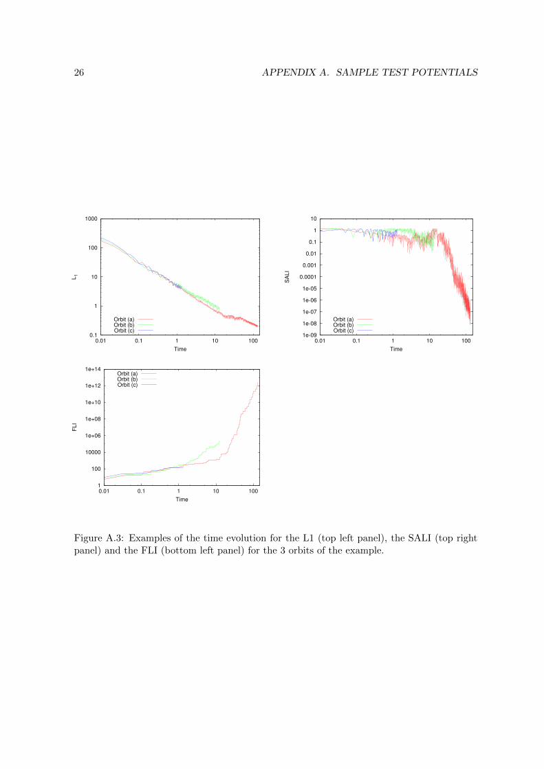
which shows that orbit (a), as well as orbits (b) and (c), did not saturate before they reachthe total integration time (i.e. 130, 13 and 1.3 u.t., respectively).
We show in Fig. A.3 the results for the three orbits and for the different CIs computed.
This example might be also useful to check the correct use of the code. To thisend, a complete pav file of this potential is provided in the web page.
26 APPENDIX A. SAMPLE TEST POTENTIALS
0.1
1
10
100
1000
0.01 0.1 1 10 100
L1
Time
Orbit (a)Orbit (b)Orbit (c)
1e-09
1e-08
1e-07
1e-06
1e-05
0.0001
0.001
0.01
0.1
1
10
0.01 0.1 1 10 100
SA
LI
Time
Orbit (a)Orbit (b)Orbit (c)
1
100
10000
1e+06
1e+08
1e+10
1e+12
1e+14
0.01 0.1 1 10 100
FLI
Time
Orbit (a)Orbit (b)Orbit (c)
Figure A.3: Examples of the time evolution for the L1 (top left panel), the SALI (top rightpanel) and the FLI (bottom left panel) for the 3 orbits of the example.
Top Related