


Languages
Pages
Legal


Journal of Water and Wastewater
Engineering Association – HNU
Publication of Water and Wastewater Engineering Association at Hunan University
November 2015 • Volume 1, Issue 1

WWEA | Water and Wastewater Engineering Association at Hunan University
Letter from the Editor
Welcome to the first issue of Journal of Water and Wastewater Engineering Association at Hunan
University. We have made this journal to better introduce visitors to our exceptional student research,
education, and outreach programs.
There has never been a more exciting time to pursue water and wastewater engineering as a career
path. Our engineers imagine, design, construct, manage, maintain, and renew the physical
infrastructure of water and wastewater systems. These critical activities touch many areas of our daily
lives, including buildings and structures, transportation systems, water distribution, environmental
protection, and energy production. With growing populations, increasingly scarce resources, and the
effects of water quality deterioration, society is demanding more from water and wastewater engineers
every day, and in many respects our future quality of life depends on the ability of our engineers to
meet these challenges.
This publication is the official journal of the Water and Wastewater Engineering Association at Hunan
University. It contains our student articles on all aspects of the science and technology of water and
wastewater. A broad outline of the journal's scope includes but is not limited to: treatment processes
for water and wastewaters; municipal, agricultural and industrial, including residuals management;
water quality monitoring and assessment, based on chemical, physical and biological methods; Studies
on inland, tidal or coastal waters and urban waters, including surface and ground waters, and point
and non-point sources of pollution; the limnology of lakes, impoundments and rivers; solid and
hazardous waste management, including source characterization and the effects and control of
leachates and gaseous emissions; environmental restoration, including soil and groundwater
remediation. New developments in engineering design and construction are also featured.
In this fall semester of 2015, I taught an 8-week long introductory course of Water & Wastewater
Engineering in English at Hunan University. Each student group in my course contributed an article
to this first issue. Your comments and feedback to help the students improve their English writing skills
are welcomed and appreciated. You may also contact us if you would like additional information or
consider submitting a manuscript for publication in our journal.
Sincerely,
Hao L. Tang, Ph.D., P.E.
Editor
Journal of Water and Wastewater Engineering Association – HNU

J. Water Wastewater Eng. Assoc. - HNU 2015, 1 2
Papers
3 Sludge treatment and management. Jin Li, Pingwen Shi, and Hongwen Su
9 SBR activated sludge. Li Lu, Luyao Hu, and Cuiting Chen
15 A review on disinfection by-products. Baoquan Zhu, Bingwei Fan, Peng
Chen, and Danyang Liu
23 Industrial wastewater. Yaping Wang, Limei Bao, Shijia Liu
28 Effect of heat treatment on adsorption performance and photocatalytic
activity of TiO2-mounted activated carbon cloth. Yifan Yang, Yue Wang, and
Tianpeng Su
37 Improving electro-adsorption ability of activated carbon electrodes through
titanium modification. Yujia Zhai, Lu Zhang, and Yanbing Liu
44 A review of electrosorption selectivity of ions using activated carbon
electrodes in capacitive deionization. Zheng Li, Yishuang Wang, and Jinyan
Peng
52 Advanced oxidation process. Ting Li, Yongjia Qian, and Ziyang Wang
56 Water distribution. Bowen Xu, Jiajun Zhang, and Jing Tang
62 Activated carbon adsorption technology in the application of water
treatment. Dong Lin, Weijing Li, and Shifan Deng
68 Water quality management in China: situation, problems and challenges.
Haifeng Tang, Hao Yang, and Du Yu
72 Study on utilization of surplus sludge. Yingtong Chen, Qiwei Liu, and Linhai
Wang
76 Study on micropollutants. Hao Long, Yuze Li, and Xupeng Li
81 Nitrate removal from water by adsorbents. Yishuai Pan, Gemian Liao,
Guoliang Zhang, and Jieping Zhu
88 Advanced oxidation processes for water treatment. Xi Zhao, Jiyong Bian,
and Wenjie Jiang
94 Effect of drinking water quality on public health. Huiping Lin, Tingfei Mao,
and Qiyi Wu
98 The wastewater treatment of photoelectrocatalytic oxidation technology.
Yuchao Zhang, Xingan Bo, and Di Zhao
104 Progress in study of electrode materials and application on capacitive
deionization. Qiyu Liu, Jianqing Liu, Zijun Wang, and Kuan Z. Huang
111 Special treatment of industry sewage. Jing Wang, Ziju Wang, and Jiajian
Luo
120 Water pollution investigation for public health. Jiajun Mi, Daning Jiang, and
Lizhong Lan
127 Municipal water supply and drainage pipe network. Maosheng Lv, Xiaoyu
Zhang, and Bin Yao
132 Study on the formation of fat, oil, and grease (FOG) deposits in sewer pipes.
Zhengyang Gu, Wuyi Huang, Shunyi Wang, and Ansheng Zhou
138 The brief introduction of forward osmosis: mechanisms and developments.
Baolin Zhang, Yunqing Liu, Zhilin Tan, and Wen Xiong
146 Reaction mechanism and factors of UV/H2O2 advanced oxidation process.
Lijuan Cao and Ying Xia
J. Water Wastewater Eng. Assoc. - HNU 2015, 1 3
J. Water Wastewater Eng. Assoc. – HNU, 2015, 1, 3-8.
English for
Water and Wastewater
Engineering Major FALL 2015
http://www.minnwater.com/research/?p=149
Article
Sludge Treatment and Management
Jin Li 1, Pingwen Shi
2, Hongwen Su
3
1 College of Civil Engineering; E-Mail: [email protected]
2 College of Civil Engineering; E-Mail: [email protected]
3 College of Civil Engineering; E-Mail: [email protected]
Academic Editor: H.L. Tang
Received: 5 November 2015 / Accepted: 13 November 2015 / Published: 18 November 2015
Abstract: With the rising of the quantity of urban waste water effluent, sludge generated
from sewage treatment plants is increasing. We list several common methods of sludge
treatment abroad and domestic to discuss problems generated when treating sludge. There
are pros and cons in every way and technology is developing. To choose a better way for
China, we should consider different trends in different cities.
Keywords: sludge treatment; complex components; landfill; land using
As the by-product in sewage treatment process, sludge is a kind of complicated heterogeneous
thing consisted of organic fragments, bacterium, inorganic particles, gel and so on. It has high moisture
content(up to 99%) and much organic matter, which makes it easy to decay and stink. It is aggregation
of colloidal particles which is something between liquid and solid, but belongs to solid waste. With the
equal importance as sewage, sludge was once unnoticed for a long period. However, as pollution
caused by raw sludge is increasingly serious, problems about sludge treatment and management
attracted wide attention and are waiting for better settlement.
Except decaying, sludge generated from sewage treatment plants also contains a mass of
pathogenic bacteria, parasite eggs, heavy metals like chromium, mercury and poisonous carcinogens
like dioxin and PCBs which are hard-degraded[1]
. If amassed sludge discharged without being treated,
CE 06015

J. Water Wastewater Eng. Assoc. - HNU 2015, 1 4
once eroded by rainwater, it will cause the second pollution to soil and groundwater and do harm to
public health. So as a by-product in waste water treatment process, whether it can be treated timely and
properly has become a crucial factor of affecting the normal running of sludge treatment plants and
producing environmental effects. Scientists domestic and abroad are actively finding more scientific
and economical ways of sludge management.
Sewage sludge, which mainly include sewage from centralized sewage treatment facilities,
riverways, sewer and trench. Among them, centralized sewage sludge is the most difficult to be
treated . In recent years, the quantity of waste water effluent rising by 5% annually, accompanied by
increasing amount of sludge waiting to be treated. Sludge management is highly important part in
developed countries and investment in this section account for 50%~70% of all investment in sewage
treatment, whereas it is only occupied 20%~50% domestic[2]
. This obviously hinders the progress of
sludge treatment and management.
It is worth mentioning that sludge has abundant organic matter, nitrogen, phosphorus, potassium
and trace elements. It can be used as slow acting fertilizer which can lower density and add porosity of
soil. It also can improve soil's capacity of water and nutrient preserving and can promote growth and
enhance permeability of plant roots. Besides, it has great effect on improving destroyed land. Hence
some sewage treatment plants use sludge in gardening, farming and reclamation of abandoned mines[2]
.
But these sludges are always untreated, with their owners ignoring the complex components in it. Once
harmful things like virus, heavy metal and radioactivity element slip into food-chain system of human
being, disease would start spreading.
In summary, it matters so much on how to treat sludge better all around the world. At present,
ways to management sludge mainly include land application, heat utilization, sanitary landfill and so
on. Countries choose and set their own technical standard and main treatment method according to
different national conditions, resource, technology and economic development[3.4]
. For instance, sludge
is treated as hazardous waste in Europe, America and Japan.
How to take all factors into account and improve sludge management efficiency scientifically and
rationally? We will elaborate on some treatment methods and discuss this question in the following
parts.
1. Methods of Sludge Treatment and Management
1.1The traditional way of sludge treatment
1.1.1 landfill
The sanitary landfill of sludge treatment began in he 1960 s which is a relatively mature sludge
treatment technology.The advantage of this technology is that it has a large handling capacity and
can solve the problem quickly.The disadvantage of landfill is it occupy a large amount of land
resources which lead it difficult for us to find a right place to set up new landfill . And in
the infiltration of rain and erosion role, the sludge under the land may
contaminate groundwater.On the other hand, organic matter in sludge is easy to fermentation and

J. Water Wastewater Eng. Assoc. - HNU 2015, 1 5
produce poisonous gas of atmospheric pollution.So the subsequent processing of the landfill sludge
need to cost a large sum of money[5]
.
1.1.2 land use
The processed sludge can be used as inorganic or organic fertilizer and it can also be used to
restoration the destroyed land[6]
. Due to the sludge contains a lot of organic matter and trace
elements,it can enhance soil fertility ,increase crop yield and improve the bad situation of soil.
However, pathogenic microorganisms,heavy metals and harmful ingredients in the sludge will
pollution soil and water. So harmful substance in the sludge have to be reduced to a certain standard.
1.1.3 burning[7]
Burning can solve the subsequent processing problem of sludge treatment which is a method to
solve the sludge once and for all. Sludge incineration can reduce the sludge volume effectively and can
also reduce the harm of sludge to the environment.But in order to prevent harmful gases pollute the
atmosphere,the incineration temperature need higher than 850 degrees. At the same time,the flue gas
emission in the process of burning is also a problem that need to control.
1.2 sludge disposal technologies
1.2.1 building materials using[6~8]
We can burn urban sludge in cement kiln that can reduce energy consumption.At the same time,
this way can consume burning ash which reduces the economic cost greatly.But the excessive sludge
added will cause the loss of cement quality,and can also cause the pollutant in building materials over
the level.
1.2.2 other sludge treatment technologies
Now there are a lot of sludge treatment method being successfully researched, such as
manufacturing fibreboard, production ceramsite[9,10]
, and dry distillation method .But due to various
reasons, these technologies don’t have widely commercial application.
2.Thinking and Improvement
After the treatment of sludge and abandoned under the natural environment (ground, underground,
water) or reuse to achieve long-term stability and to the ecological environment without the final
disposal way of the adverse effects.According to the above definition, the main sludge disposal
methods are landfill, casting into the sea, land using and production of building materials.China
accepted the 3 international agreements in 1994, and promised to stop the disposal of industrial waste
and sewage sludge on sea in February 20, 1994.[1,11]
The burning is the most thorough treatment of
reduction, the sludge weight reduced to the original 10%, the ash after burning easy to landfill or
comprehensive utilization, so in normal circumstances will also burn as a way of disposal.So the
feasible methods of sludge disposal are sanitary landfill, land using, landscaping, production of
building materials, burning.In the sludge disposal, the countries in the world are different according to
the specific circumstances.
2.1 World’s situation

J. Water Wastewater Eng. Assoc. - HNU 2015, 1 6
According to the relevant information, the world's countries of sludge production and processing
methods, statistics, see Table 1
Table1
Sludge production and processing methods in the other countries[12]
Country
Total amount of
sludge
(Dry sludge t/a)
Percentage of each treatment method(%)
Agricultural Burning Landfill Marine dumping
Switzerl
and 250000 50 20 30
German
y 2750000 25 10 65
Denmar
k 150000 43 28 29
Sweden 180000 60 40
Holland 280000 53 10 29 8
Austria 250000 28 37 35
Italy 800000 34 11 55
Ireland 23000 23 34 43
Spain 300000 61 10 29
Portugal 200000 80 12 8
Britain 1500000 51 5 16 28
France 900000 27 20 53
U.S.A 7690000 45 3 21 30
Japan 9 55 35
(Material source Oslo Commission Water Research Center.Water Services Association EWPCA
。)
Thus it can be seen that different countries and regions according to local conditions, take the
suited to their national conditions of sludge treatment and disposal technology route, considering the
main factors for the industrial structure, land resources, degree of urbanization and other. According to
the specific conditions of China, sanitary landfill, landscaping, burning and production of building
materials is feasible means of disposal.
In view of the disadvantages of various methods, our country should adjust accordingly.
2.2 Methods and Improvement
2.2.1 Sanitary Landfill
Sludge landfill has Direct landfill and Sanitary landfill two disposal methods. Direct landfill is
that after simple sterilizing sludge is dumped directly into the lowlands and valleys.Sanitary landfill is
that sludge is transported to landfill and mixed with garbage to harmless landfill.[13]

J. Water Wastewater Eng. Assoc. - HNU 2015, 1 7
2.2.2 Sludge incineration
Sludge incineration is not only a kind of treatment technology but also a kind of disposal method.
At present, there are two kinds of sludge incineration methods which are Directly mixed incineration
and Incineration after dry.
Directly mixed incineration is that sludge after dewatered contents of about 80% of the wet using
high-pressure pump directly invest and add into the Thermal power plant, Refuse incineration plant’s
boiler to burn. The proportion of sludge in fuel is generally not higher than 20%.
The commonly used method of sludge drying is to send the sludge to special thermal drying
equipment to dry directly or indirectly, so that the moisture content of the sludge can be reduced to
30%.So a large amount of water is evaporated at low temperature, and does not enter the combustion
furnace, which can not only reduce the energy consumption, but also avoid the impact of a large
amount of water into the boiler.
2.2.3 Land using
The advantages of sludge land using is not to need to landfill volume. The resources of the sludge
can be effectively utilized, but the disadvantage is that there is a certain environmental risks, the
harmful substances in the sludge may have adverse effects on groundwater, surrounding water and
crops.
In the United States, 30 years ago, the pre treatment plan to ensure that the sewage sludge in the
sewage sludge of the standard, to pave the way for sludge land use; 10 years ago, the 503 Sludge Rules
to further ensure the safety of the sludge land use, exempt from the worries.
Referring to the successful experience of foreign sludge land use, we must carry out strict
pretreatment of industrial wastewater, so that the sludge utilization must comply with the requirements
of relevant national standards, and resolutely put an end to heavy metals and other toxic substances
into the sewage sludge.At the same time, it is necessary to monitor the contents of heavy metals and
other toxic substances in soil. [3]
3.Conclusion
Treatment and disposal of sludge has become a difficult problem in environmental comprehensive
management, and it is very important to determine the appropriate disposal method for the
implementation of the sludge project.For China, the development trend of sludge disposal method is
also consistent with foreign countries.The disposal method of sludge has advantages and
disadvantages.For China, it is not possible to be confined to one kind of disposal method, which should
be based on the nature and quantity of local sludge, investment situation and operation management
cost, environmental protection requirements and relevant laws and regulations, the dynamic of urban
development and the utilization of sludge, After the comprehensive consideration, and also need to
adapt to the overall development trend of the city.
Acknowledgments
Thanks for Mr.Hao Tang’s instruction
Author Contributions
1. Abstract & Paragraph 1~6
J. Water Wastewater Eng. Assoc. - HNU 2015, 1 8
2. Part 1
3. Part 2 & 3
References
[1] Ye Zirui. National and International Sludge Disposal and Management Analysis[J]. Environmental
Sanitation Engineering, 2002, 10(2): 85–88.
[2] Shan Li. Sludge treatment and disposal presents China a cleaner future[J].Focus Monthly, 2007(3):
44–46.
[3] Zhang Qirong, Pu Xiaojing. Current Status of China’S Urban Sewage Plant Sludge
Disposal[J].Environmental Science and Management, 2015, 40(4): 86–89.
[4] B, Jimenez,JA Barrios,JM Mendez,J, Diaz. Sustainable sludge management in developing
countries[J]. Water Science and Technology, 2004, 49(10): 251–258.
[5]Yan Zhibin,Sun Kai,General situation of development of sludge in foreign countries[C],China
petroleum chemical engineering survey and Design Association of thermal,National Chemical
Engineering Thermal Design Technology Center Station 2012 annual meeting papers set 2010:284-292
[6]Xiong Zhenghu.Study on treatment and resource utilization of sewage sludge in China[J],Journal of
Tianjin Institute of Urban Construction,1999,5(3);6-9.
[7]Guo Yan,Current status of municipal sludge incineration technology[J],Resource Saving and
Environmental Protection,2013(10):67-67
[8]Shi Huisheng.Research on the application of cement kiln sludge treatment to wastewater treatment
plant[J]2002,(7):8-10
[9]Zhou Shaoqi , Treatment and disposal of municipal sludge[M],Guangzhou : South China
University of Technology press,2002.
[10]Du Yinghao, Yang Xiaowen.Application of sludge thermal drying in the United States[J],China
water and wastewater,2002,19(1):90-92
[11]BemdWeibusch.Utilization of sewage sludge ashes in the brick and tile Industry[J].Wat Sci
Tech,1997,36(11):243—250.
[12]Wang Guohua, Deng Xiaolin, Ren Heyun.Approach of sludge disposal in Shanghai urban
sewage treatment plant[J].China water and wastewater,2000,16(5):19—22.
[13]Wang Shiyuan, Cui Yubo, Wang Cuilan, et al.Sludge Treatment Technology[J].Journal of Jilin
Architecture and Civil Engineering Institute,2000,17(1):25—27.

J. Water Wastewater Eng. Assoc. - HNU 2015, 1 9
J. Water Wastewater Eng. Assoc. – HNU, 2015, 1, 9-14.
English for
Water and Wastewater
Engineering Major FALL 2015
http://www.minnwater.com/research/?p=149
Article
SBR Activated Sludge
Li Lu 1,
*, Luyao Hu 2,†
and Cuiting Chen 3
1 School of Civil Engineering, Hunan University,the second class of Water Supply and Drainage
Science and Engineering
Hunan University, Dezhi Yuan
Li Lu E-Mails: [email protected] Tel:18390857040
2 School of Civil Engineering, Hunan University,the third class of Water Supply and Drainage
Science and Engineering
Hunan University, Dezhi Yuan
Luyao Hu E-Mails: [email protected] Tel:15575829862
3 School of Civil Engineering, Hunan University,the third class of Water Supply and Drainage
Science and Engineering
Hunan University, Dezhi Yuan
Cuiting Chen E-Mails: [email protected] Tel:15211020204
These authors contributed equally to this work:
Li Lu :Introduction
Luyao Hu:Work principle and operation
Cuiting Chen :Improvements and strengthening of SBR process function
Academic Editor: H.L. Tang
Received: 5 November 2015 / Accepted: 13 November 2015 / Published: 18 November 2015
Abstract: SBR process and its new technology, also attract our experts' attention and has been
applied.SBR is applied in municipal wastewater treatment,besides industrial waste from the treatment
of beer, leather, food production, meat processing and pharmaceutical, and get good effect.Now, some
ancillary equipment include several forms decanter is developed. Keywords: SBR activated sludge improvement
1. Introduction
CE 06015

J. Water Wastewater Eng. Assoc. - HNU 2015, 1 10
1.1 Overview
With the strengthening of environmental awareness , bearing the brunt of sewage treatment , the
construction of urban sewage treatment plant will be the focus of future environmental projects , then
selecting the appropriate construction of the sewage treatment process will become subject . SBR
wastewater treatment process develops rapidly in recent years , so it becomes the primary
consideration . SBR process belongs to the batch activated sludge process for treatment of municipal
sewage , setting anoxic / aerobic , water quality and quantity adjustment, precipitation as a whole .
The process is short , with strong shock load capacity and operational flexibility large as needed by
adjusting the process . In addition , you can change the water quality , and accordingly reduce
operating costs , and meet changing water quality requirements and have savings , small footprint , and
easy management[3]
. This process requires high operating characteristics of automated , easy operation
and management and water quality stability . Based on the above advantages , the sewage treatment
plant has been widely adopted[4]
.
1.2Process and characteristics :
Sequencing Batch Reactor Activated Sludge Process (abbreviated to SBR Activated Sludge) is also
known as sequencing batch activated sludge process which is a treatment method based on traditional
activated sludge wastewater treatment improved on[1]
. The sewage treatment mechanism is the same
with activated sludge treatment mechanism . SBR activated sludge process is in a single reactor ,
according to the time sequence of inlet water , reaction (aeration) , precipitation , water , standby (idle)
and other basic operations from sewage inflow to the standby time ending for a cycle operation , so
the cycle goes round and begin again , so as to achieve the purpose of sewage treatment . SBR process
is an ideal plug-flow process in terms of time , but on the reactor itself is mixed state is still
completely mixed , and therefore resistant to shock loads and reaction driving force big advantage . It
is used to treat domestic sewage , with less treatment structures[2]
.
As the picture shows , the main characteristics of the process system is the use of a mixture of
degradation and precipitation in one reactor set of organic pollutants---Intermittent aeration aeration
tank [8]
.
And we also can know from the picture , compared with continuous activated sludge system , the
system consists of simple processes , so it need not set the sludge return device and secondary
sedimentation tank , and the volume of aeration tank is also smaller than continuous activated sludge
system , both construction costs and Operating costs are relatively low . Moreover , SBR activated
sludge treatment system also has the following features .
Figure 1

J. Water Wastewater Eng. Assoc. - HNU 2015, 1 11
1) In most instances (Including industrial wastewater treatment) , there is no necessary to set a
regulation pool ;
2) The value of SVI is relatively low , and the sludge is much easier to precipitate . Under normal
circumstances , it does not produce sludge bulking phenomenon ;
3) By adjusting the operating mode , in a single aeration tank Nitrogen and phosphorus removal
reaction can be performed ;
4) The automation instrumentation like the electric valve of application , Level Meter, Automatic
timer , Programmable Logic Controller and so on , may make this process to achieve full
automation , and it can controlled by the central control room ;
5) If it is going to be managed properly , the quality of the treated water will be better than
continuous activated sludge system ;
6) The sludge settling performance of SBR is good , and the water content of the residual sludge can
be designed according to the 99.2% .
2.work principle and operation
In principle,we can see SBR as a political reform of activated sludge process,a new operating
mode.The continuous plug flow aeration tank is a plug flow in space,although the batch activated
sludge aeration tank is completed mixed in the flow regime,in terms of the organic matter degradation,
it's a plug flow in time.In a continuous plug flow aeration tank, the degradation of organic pollutants is
along with the space, and in batch activated sludge treatment systems, it’s along with the passage of
time.
The realization of the SBR's Intermittent running is by operating its main reactor-aeration.The
operation of aeration concludes five processes such as 1)inflow 2)reaction 3)Precipitation 4)discharge
5)idle.
2.1 inflow process
Before wastewater injected, the reactor was in the last idle process, treated wastewater has been
discharged,and the reactor remained a high concentration of activated sludge mixture.
Water injects into the reactor till fill with it,then reacts with other things, in this sense, the reactor
play a regulatory pool role, therefore,the reactor have some adaptability to the changes of water quality
and quantity.
Water injects,and the water level rises.We can add other operations according to the requirements
of the other processes,such as aeration which not only get the effect of pre-aeration,but also the sludge
can resume its active.
The spent time depends on the actual drainage situation and equipment conditions.According to the
process performance requirements,short injection time is appropriate,it's really difficult.
2.2 reaction process
This is a major step in this technology.After water injection reaching the proper height, the reactor
responses and operates.According to the purpose of wastewater treatment,we should take the
appropriate technical measures,such as aeration can achieve BOD removal, nitrification and
phosphorus absorption,and slow agitation can achieve denitrification.
According to demand,BOD removal-nitrification-denitrification was happened continuously in the
reactor. BOD removal -nitrification require long time aeration,but during the denitrification, aeration
J. Water Wastewater Eng. Assoc. - HNU 2015, 1 12
should be stopped which make the reactor into the anoxic or anaerobic conditions,and stirring
slowly.At the same time,for adding electron acceptor to the reactor,formaldehyde or a small amount of
organic wastewater was required.
In the latter part of this process, short trace aeration is also needed,for blowing off the vicinal
bubbles or nitrogen, in order to ensure the normal precipitation process.
2.3 precipitation process
This process corresponds to the secondary sedimentation tank of activated sludge.Stopping aeration
and stirring which make the mixture is in a quiescent state and activated sludge separates with water.
As the process is still precipitation, sedimentation effect is usually good.
The time precipitation processes takes is substantially equal to secondary sedimentation tank,
usually 1.5-2.0h.
2.4 discharge process
The supernatant after precipitation discharged as treated water. Until the lowest level, a portion of
the residual active sludge in the reactor can be used as seed.
2.5 idle process
This is a period after the treated water discharged, the processor is standstill and waits for the
beginning of the next stage.This process time should be based on site-specific circumstances.
3 Improvements and strengthening of SBR process function
SBR treatment process is not only a simple system, but also a biological wastewater treatment
technology of good treatment effects. And , it is a new type of sewage treatment process, so in the
terms of theory, design and operation, there are still the problems to be studied and discussed.
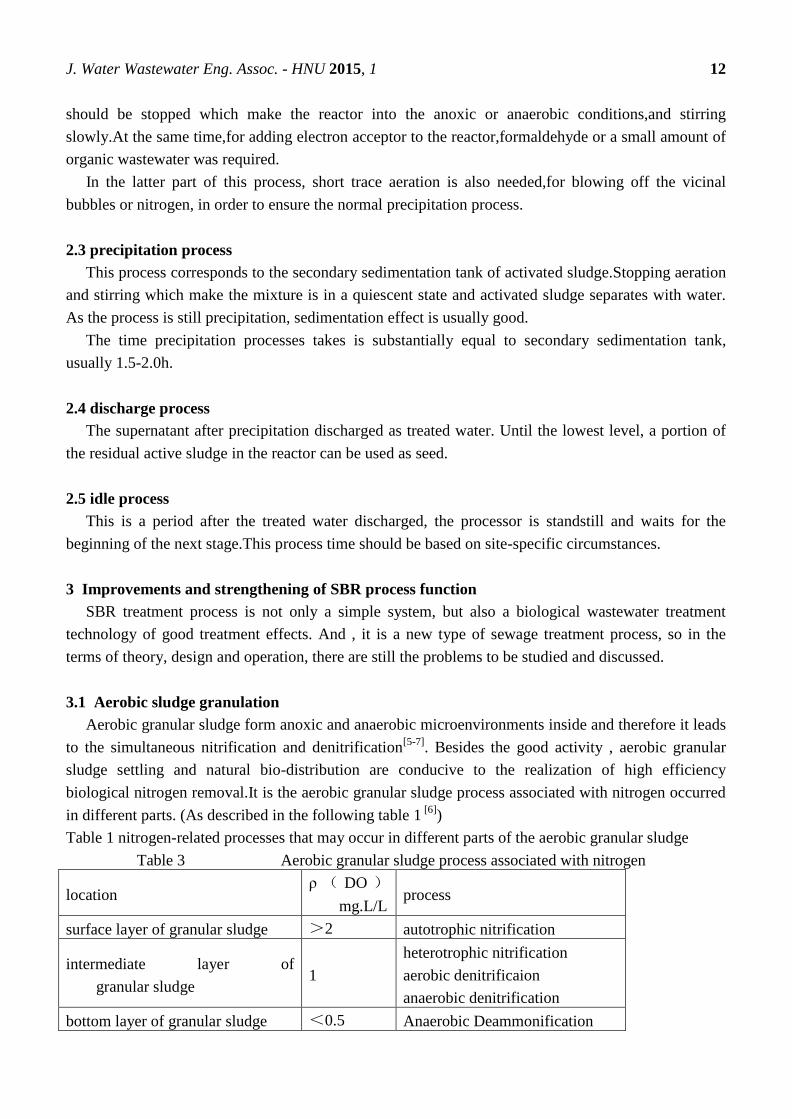
3.1 Aerobic sludge granulation
Aerobic granular sludge form anoxic and anaerobic microenvironments inside and therefore it leads
to the simultaneous nitrification and denitrification[5-7]
. Besides the good activity , aerobic granular
sludge settling and natural bio-distribution are conducive to the realization of high efficiency
biological nitrogen removal.It is the aerobic granular sludge process associated with nitrogen occurred
in different parts. (As described in the following table 1 [6]
)
Table 1 nitrogen-related processes that may occur in different parts of the aerobic granular sludge
Table 3 Aerobic granular sludge process associated with nitrogen
location ρ ( DO )
mg.L/L process
surface layer of granular sludge >2 autotrophic nitrification
intermediate layer of
granular sludge 1
heterotrophic nitrification
aerobic denitrificaion
anaerobic denitrification
bottom layer of granular sludge <0.5 Anaerobic Deammonification
J. Water Wastewater Eng. Assoc. - HNU 2015, 1 13
3.2 Standby and water process and a combination of various functions
1) SBR technology has certain regulatory functions, playing a role in balancing quality, quantity, and
these take effects by the standby and water processes[8]
.
2) Combination with hydrolysis-acidogenosis reaction. Improving the biodegradability of
wastewater by hydrolysis-acidogenosis reaction, it helps the next process "aeration reaction" effect.
Duration of hydrolytic acidification should be determined by considering the time required of water
conditions and hydrolysis-acidogenosis reaction.
3) if the time of standby operation is too long, in order to prevent the mixed liquor as Sewage seed
left in the reactor from passivated , continuous aeration should be taken . Also before the start of the
new cycle of work, aeration for a while was an available way to renew,improve and strengthen the
Sewage seed.
3.3 The efficien cy of nitrogen and phosphorus
Professor Zeng Wei used a two-stage SBR process to treat organic industrial wastewater with high
content of nitrogen and ammonia[9-11]
. The experiment result Indicated that, compared with the SBR
method for single, two-stage SBR method reduce further water COD, while also avoid high organic
loading on nitrification of shock, and the way not only improve efficiency, can also save the budget of
energy and Carbon Source.
3.4 oxygen and aerobic
SBR process is sense of the flow of time. Conditions of organic matter, rate of bacteria growth and
the rate of oxygen consumption is gradually reduced over time[8]
. So , it is appropriate for the SBR
reactor to using the technology of decreasing with time of aeration.
4.Conclusion
SBR process and its new technology, also attract our experts' attention and has been applied.SBR is
applied in municipal wastewater treatment,besides industrial waste from the treatment of beer, leather,
food production, meat processing and pharmaceutical, and get good effect.Now, some ancillary
equipment include several forms decanter is developed.
References and Notes
1. Zijie Zhang . Drainage engineering . Beijing: China Building Industry Press , 2000
2. Peilu Zhang , SBR analysis and treatment of common problems aeration tank [Papers] - Cai Zhi ,
2012 (6)
3. Yihua Zhao , SBR wastewater treatment process and its automatic control system [Papers] -
TIANJIN CONSTRUCTION SCIENCE AND TECHNOTOGY , 2001 (3)

J. Water Wastewater Eng. Assoc. - HNU 2015, 1 14
4. Liu Xingkui . Han Xiaoqin SBR sewage treatment process design and application [J] Gansu
Science and Technology 2014 (18)
5. Chaoran Lu, Xiaojian Zhang, Yue Zhang etc. The study of influence of Granular sludge SBR
process for biological nitrogen and phosphorus removal [J]. Environmental Science Journal,
2001,21 (5) 577~581
6. Guojing Yang,Xiaoming Li,Guangming Zeng etc. Study on aerobic granular sludge for
simultaneous nitrogen and phosphorus removal of new development[J].Industrial Water and
Wastewater,2004,35(6),10~13
7. Shan Xie,Xiaoming Li,Guangming Zeng etc.Nitrogen removal characteristics of aerobic
granular sludge in SBR system research[J]. Chinese Environmental Science,2004,24(3),355~359
8. Zijie Zhang,Xiasheng Gu etc. Drainage Engineering Part ii.
9. Yunlong Yang,Qibing Chen. Status and Development of SBR Process[J]. Industrial Water and
Wastewater,2002,33(2),1~3
10. Wei Zeng,Yongzhen Peng,Shuying Wang etc. Two-stage SBR method for removal of Organics
and nitrification-denitrification[J].Environmental Science,2002,23(2),50~54
11. Dao Chen, Yongzhen Peng,Tianjun Wang etc. Two-stage SBR and the common law of
comparative research[J]. Technology of Water Treatment,2002,28(6),335~338
J. Water Wastewater Eng. Assoc. - HNU 2015, 1 15
J. Water Wastewater Eng. Assoc. – HNU, 2015, 1,15-22.
English for
Water and Wastewater
Engineering Major FALL 2015
http://www.minnwater.com/research/?p=149
Article
A review on disinfection by-products
Baoquan Zhu1, Bingwei Fan
2,†, Peng Chen
2,† and Danyang Liu*
1 Department of Water Engineering and Science, College of Civil Engineering, Hunan University,
Changsha, Hunan 410082, China; E-Mail: [email protected]; 2 Department of Water Engineering and Science, College of Civil Engineering, Hunan University,
Changsha, Hunan 410082,China; E-Mails: [email protected]; [email protected];
† These authors contributed equally to this work.
* Department of Water Engineering and Science, College of Civil Engineering, Hunan University,
Changsha, Hunan 410082, China; E-Mail: [email protected];
Tel.: +86 188-9065-6228
Academic Editor: H.L. Tang
Received: 5 November 2015 / Accepted: 13 November 2015 / Published: 18 November 2015
Abstract: Disinfection by-products (DBPs), a series of unintended health hazards
generated during drinking water disinfection process, have been explored for more than 30
years. Since chloroform was firstly indentified as a halogenated-DBP in chlorinated
drinking water in 1970s, many efforts have been devoted to balancing the risk between
pathogenic microbes and health effects related to DBPs. In this paper, we make a
comprehensive review on DBP analytical methods, regulations and guidelines, emerging
DBPs, and control strategies.
Keywords: Disinfection by-products; Analytical methods; Regulations and guidelines;
Emerging DBPs; Control strategies
1. Introduction
CE 06015

J. Water Wastewater Eng. Assoc. - HNU 2015, 1 16
Disinfection of Drinking water have been successfully used to kill or inactivate pathogens. Before
its widespread application, millions of people have died from waterborne diseases such as cholera and
typhoid[1, 2]. However, during the disinfection process, some unintended hazardous compounds
produced by the reaction between disinfectants and natural organic matters (NOM)[3, 4]. Currently,
more than 600 DBPs have been reported in the literatures. Some of these DBPs including
trihalomenthanes (THMs), haloacetic acids (HAAs), and bromate, have been regulated in a number of
countries[5]. For example, USEPA regulated THM and HAA in drink water at the limit of 80ug/L and
60ug/L, respectively[6, 7]. Researches now are conducted worldwide to understand DBP formation,
occurrence, health effects, and control methods.
Common chemical disinfectants include chlorine, chloramines, chlorine dioxide, ozone[8]. Because
of their powerful oxidation capacity, they can react with organic matters in raw water to form different
kinds of DBPs. Chlorinated water would result in high level THM formation[9]. N-DBPs may
produced when chloramines are used. Some inorganic DBPs such as bromate and chlorite, would
occur when ozone and chlorine dioxide are used, respectively[8]. Many of these DBPs show adverse
health effects like resulting cancer[2].
The objective of this paper is to review on analytical methods for DBPs, regulations and guidelines
in the world, and control strategies. We also provide an overview of emerging DBPs.
2. Analytical methods
There are a large amount of methods, which including SPE-derivatization-GC-ECD,LLE-
derivatization-GC-ECD,P&T-GC-PID-ELCD, etc. These methods are used to detect DBPs
(Disinfection byproducts) in drinking water, as to DBPs, which involving THMs and some volatile
DBPs. Though different DBPs need different methods, For example, methods IC-CD and IC-PCR-UV
for bromate, methods LLE-GC-ECD for HAAs, etc..Generally speaking, these methods can be
separated two categories, one kind of method is gas chromatography with electron capture detector to
detect organic DBPs; the other methods are ion chromatograph with conductivity detector to detect
inorganic DBPs. In addition to two principals, other methods sometimes are used to detect it, which
including GC-mass spectrometry, IC-inductively coupled plasma-MS and colorimetric. On sample
pretreatment ,which including liquid-liquid extraction or purge and trap for organic DBP
preconcentration; with regard to polar DBPs like carbonyl compounds, we need to use chemical
derivatization. The above mentioned methods, which are issued and approved by the US
Environmental Protection Agency.
Our country also had issued and mentioned some methods about DBPs measurement, which were
included in GB/T 5750.10-2006[10]. When those methods were used to detect DBPs, a concept was
mentioned in the column, which named the detection limit. The scope of detection limit would directly
influence suitable capacity for detecting substances; Generally speaking, different substances have
embraced different scope. For example, Head space can be used for the determination of THMs in the
samples, which has embraced high detection limit that can be suitable for measurement of BDCM
(bromodichioromethane) and DACM and cannot be suitable for measurement of bromoform in
drinking water. Besides, the titration method can be used to measure chlorite and chlorate with the
precondition of reacting with potassium iodide, at the same time, choosing a suitable method to reduce
J. Water Wastewater Eng. Assoc. - HNU 2015, 1 17
the influence of other oxidizing agents is crucial to ensure measurable accuracy. Conventionally, GC-
MS method and LC-MS method are widely used for the detection of DBPs in drinking water[9].But
the GC-MS method is major used for the determination of unknown DBPs, such as HAAs
,haloaldehydes and haloketones in the literature[13]. The LC-MS method is used for the determination
of polar DBPs. For example, when we have used it to measure HAAs, the method has apparently
advantage that LC-based method can directly inject in water samples, moreover, the method has low
enough detecting limit, which can increase the suitable scope of this method. So, LC-MS methods are
increasing used for this aspect.
Above all mentioned, LC-MS method is similarity with GC-MS method, which is especially used
for the identification of high polarity or molecular weight[11,12], which embraced a crucial
instrument--LC-electrospray ionization (ESI). The instrument has the fast selective detection of
chlorinated, which widely using precursor ion scan mode[14]. Other detecting methods are rarely used
for the identification of DBPs in drinking water.
3. Regulations and guidelines
Nowadays, the standards for drinking water enforced in China is GB5749-2006[15]. That regulates
TTHM and 13 individual DBPs. In one respect, TTHM is ruled at 1ᵃ. The method to calculate TTHM
is based on a ratio . On the other hand, the standards regulate chloroform, BDCM,DCAA and
formaldehyde at 60μg.L⁻¹, 60μg.L⁻¹, 50μg.L⁻¹ and 900μg.L⁻¹, severally. In the US, TTHM, HAA5,
bromate and chlorite are under the Stage 2 D-DBP Rule that was promulgated in 2006 by the
U.S.EPA[16]. The Stage 2 D-DBP Rule stipulates TTHM, HAA5, bromateand chlorite at 80μg.L⁻¹,
60μg.L⁻¹, 10μg.L⁻¹ and 1000μg.L⁻¹,respectively.
Canadian guidelines for drinking water[17] is similar to that in the US. But the former include
nitrosamines and the latter is contrary. Especially, TTHM and HAA5 are calculated on the locational
running annual average (LRAA). The two DBPs are regulated at 100μg.L⁻¹ and 80μg.L⁻¹, severally.
Another four DBPs, bromate, chlorite, chlorate and NDMA regulatory limits are 10μg.L⁻¹,
1000μg.L⁻¹, 1000μg.L⁻¹ and 40ng.L⁻¹, severally.
As regards the European Union, the EU directive for drinking water only rules two DBPs, TTHM
and bromate, at the value of 100μg.L⁻¹ and 10μg.L⁻¹, severally[18]. But the countries of the EU may
regulate not only TTHM and bromate but also other DBPs. And the limits of regulated DBPs can be
more rigid than the EU directive. For instance, the maximum contaminant level (MCL) for the THM4
is 50μg.L⁻¹ in Germany. And the value in Austria is 30μg.L⁻¹[19]. Current WHO guidelines [20]for
drinking water was promulgated in 2011. The international standards list TTHM which is calculated on
a ration. Rather, another 14 individual DBPs are regulated at value of concentrations. For example, the
standard value for chloroform, BDCM, DBCM and bromoform is 300μg.L⁻¹, 60μg.L⁻¹, 100μg.L⁻¹ and
100μg.L⁻¹, severally. The WHO guidelines for drinking water has a significant reference value for
many countries.
In the aspect of DBP species, the standards for drinking water in Japan[21] is similar to GB5749-
2006. However, chlorite, chlorate, and 2,4,6-trichlorophenol are not ruled but MCAA is regulated.
Another difference between GB5749-2006 and Japanese is that the latter are more stringent for BDCM

J. Water Wastewater Eng. Assoc. - HNU 2015, 1 18
and CNCI. As for Australia, the guidelines for drinking water list a total of 24 DBP parameters[22].
Australian guidelines are similar to WHO guidelines in the aspect of DBP species but the former
include.
In mainland China,5% method is adopted as the assessment method for DBPs. When more than 5%
of the tested water samples are over the regulated value, a water system is out of compliance. The
study says most of out of compliance water samples are gathered in summer or fall. In order to
decrease the influence of season, the running annual average method may be a ideal selection. The
method was adopted by the Stage 1 D-DBP Rule in the US.
4. Emerging DBPs
Emerging disinfection byproducts are detected gradually in drinking water with advancement of
analytical technology and measuring device. Drinking water disinfection is an important and necessary
water treatment program, that is to say the occurrence of emerging DBPs is inevitable. Some emerging
DBPs have higher risk than some of the regulated ones generally[24].
The DBPs of emerging concerns commonly include iodo-THMs and acids, halonitromenthanes,
haloacetaldehydes, haloamides, MX, BMX and analogs, and NDMA and so on[8,23]. The vast number
of emerging DBPs are determined existing or potential toxicity by the expert toxicological review[25].
Some countries have a focus on emerging DBPs which hadn't been regulated and set regulations and
guidlines to control them in recent years. And a recently conducted US Nationwide DBP Occurrence
Study has helped to provide focus with quantitative occurrence data for emerging DBPs that had little
or no previous occurrence information[23].
A recent discovery of halogenated emerging DBPs which are volatile (including iodo-THMs and
acids, halonitromenthanes, haloacetaldehydes, haloamides) reveal them to be morecytotoxic and
genotoxic than the DBPs are regulated in drinking water[23,8]. These volatile halogenated emerging
DBPs all can be measured by methods currently[8]. Iodo-THMs can be determined by LLE-GC-ECD,
and the detection limits are in the range of 0.01μg-0.03μg[26]. Iodoacids can be determined by the
methods which can be used to determine HAAs[26]. Trihalonitromenthanes should be analysed under
the particular analytical conditions and they are determined by GC method which should be used
injection-port temperatures during the analysis[23,8,27].
Recent methods for measuring MX, BMX and the analogs have included liquid-liquid extraction
(LLE), derivatization with BF3/methanol or acidic methanol, and analysis using GC-electron capture
detection (ECD)[8]. NDMA and other nitrosamines in drinking water commonly are low
concentrations. MS detector can meet the requirement which requires low detection limits when
measuring[8]. LC-MS-MS methods can be also used to determine nitrosamines after preconcentration
by using solid phase extraction (SPE) or LLE[28].
Enhanced coagulation is the suggested treatment by U.S.EPA for the removal of DBP precursors.
But enhanced coagulation has little effect on emerging DBPs because of its removal principle. Some
research suggests ozonation may be a good method for removal of emerging DBPs. Ozonation
destroys the precursors of a number of emerging DBPs. Ozone can reduce some emerging DBPs
formation such as NDMA. But, preozonation can increase the formation of rihalonitromenthanes
according to some research consequences. UV radiation can also reduce some emerging DBPs
J. Water Wastewater Eng. Assoc. - HNU 2015, 1 19
formation, however, similar to ozonation, medium pressure UV radiation would increase the formation
of trihalonitromenthanes[8].
5. Methods for DBPs control
Because of the high health risk potentials and strict regulations, efforts have been made to control
DBPs before, during or after disinfection. Currently, common strategies for controlling DBPs include
precursors removal, alternative disinfectants and directly removal[3].
5.1 Precursor removal
To date, the major technologies for DBPs precursor removal include enhanced coagulation, member
filtration, advanced oxidation processes and activated carbon adsorption. Different from conventional
coagulation where removal of turbidity is the main objective, enhanced coagulation aims at NOM
removal involves excess addition of chemical coagulant, strict control of coagulation pH and other
optimized coagulation conditions, thus leading to more efficient NOM removal as DBP
precursors[29,30]. However, an increased amount of coagulant will result in a increased sludge
production and may alter the sludge characteristics which would increase the cost and difficulty of
sludge handing[8]. Moreover, enhanced coagulation will lower the chlorine dose resulting in a
reduction of chlorinated DBPs and a higher concentration of brominated DBPs. Granular activated
carbon(GAC) adsorption can both effectively remove DBP precursors and DBPs. Under the Stage 1 D-
DBP Rule, GAC was suggested as one of best available technologies for DBP control[8]. Membrane
filtration is another technology for DBP mitigation. Compared to enhanced coagulation, membrane
technologies such as reverse osmosis and nanofiltration are effective in bromide removal, thus can
reduce the brominated DBPs formation[1]. In most cases, pretreatment and frequent membrane clean
are required for membrane filtration. Due to the relatively high cost and some problems like membrane
fouling, membrane technologies have not been in large scale application.
5.2 Alternative disinfectants
During disinfection, it is effective to change the type of disinfectants for DBP control. Alternative
disinfectants include chloramines, chlorine dioxide, ozone and UV. Chloramine is a weak disinfectant
with low reactivity. This makes chloramine produce a long lasting and stable disinfectants residual in
the distribution systems[8]. Although chloramination can reduce the formation of THMs and HAAs, it
will generate unexpected higher level of N-DBPs such as cyanogen chloride and NDMA[5, 9]. In
comparison with chloramines, chlorine dioxide is a much stronger disinfectant also with long lasting
time in the distribution system. Chlorine dioxide is also efficient in taste and odors control. Also,
Chlorine dioxide disinfection produce much low level common halogenated DBPs[8]. However, some
inorganic byproducts involve chlorite and chlorate are generated when chlorine dioxide is used[31]. As
investigated by Ye[32], the presence of iodide during chlorine dioxide oxidation process results in
iodinated DBPs formation. Ozone is also a very effective and strong disinfectant with high reactivity.
Because of this, it does not provide a persistent ozone residual. Ozonation of bromide containing water
will lead to the formation bromate and brominated DBPs[33].
5.3 Directly removal of DBPs

J. Water Wastewater Eng. Assoc. - HNU 2015, 1 20
As mentioned earlier, GAC can be used to remove DBPs directly. By combining GAC with
biological degradation, BAC shows many advantages in minimizing biodegradable DBPs, including
HAA, aldehydes, CH and ketoacids[34]. As indicated by Xie, for monochloroacetic acid,
monobromoacetic acid, dichloroacetic acid, and dibromoacetic acid, the effluent concentrations were
less than 1ug/L while the influent concentration was 50ug/L each[8]. Recently, some researches
focused on zero-valent iron. As investigated by Tang, zero-valent irons were effective in TCAA
reduction to MCAA and DCAA, which can be easily biodegraded by subsequent BAC[35]. Beyond
that, air stripping is regarded as a cost-effective way for directly removing volatile DBPs like THMs.
This process does not produce additional DBPs[9].
6. Conclusions
There are a large amount of methods including SPE-derivatization-GC-ECD, LLE-derivatization-
GC-ECD, P&T-GC-PID-ELCD, etc.. GC-MS method and LC-MS method are widely used for the
detection of DBPs in drinking water.
In the West, The standards in the US is similar to that in Canada. And the EU only list two DBPs
when Australia rules a total of 24. In Asia, Chinese and Japanese standards for drinking water is
similar to the WHO guidelines. The assessment method for DBPs is 5% method but it can be affected
by season.
More types of DBPs are gradually found by research of drinking water treatments. Emerging DBPs
should be regulated because of their potential risk for people's life. And the available removal methods
of them cannot meet our needs. In other words, the best method of removal emerging DBPs is what we
are exploring.
DBP control can be implemented before, during, and after its formation. Enhanced coagulation and
GAC were listed as a best available technologies by USEPA under stage 1 D-DBP rule. Alternative
disinfectants is an effective way to reduce DBPs formation during disinfection process. However,
some emerging DBPs may occur. BAC for directly remove DBPs after its formation has attracted a lot
of interests. Physical process like air stripping is also efficient in volatile DBPs minimization.
Author Contributions
Abstract, introduction, and Part 5 methods for DBP control were finished by Danyang Liu.
Part 2 Analytical methods was finished by Peng chen
Part 3 Regulations and guidelines was finished by Baoquan Zhu
Part 4 Emerging DBPs finished by Bingwei Fan.
All of the authors contributed to the conclusion.
References and Notes
1. Susan D. Richardson, Jane Ellen Simmons and Glenn Rice, Environ. Sci. Technol., 2002, 36
(9), pp 198A–205A

J. Water Wastewater Eng. Assoc. - HNU 2015, 1 21
2. Gopal, K.; Tripathy, S. S.; Bersillon, J. L.; Dubey, S. P., Chlorination byproducts, their
toxicodynamics and removal from drinking water. Journal of hazardous materials 2007, 140, (1-2), 1-
6.
3. Philip C. Singer, J. Environ. Eng., 1994, 120(4): 727-744
4. Liu, B.; Reckhow, D. A., DBP formation in hot and cold water across a simulated distribution
system: effect of incubation time, heating time, pH, chlorine dose, and incubation temperature.
Environmental science & technology 2013, 47, (20), 11584-91.
5. Bond, T.; Huang, J.; Templeton, M. R.; Graham, N., Occurrence and control of nitrogenous
disinfection by-products in drinking water--a review. Water research 2011, 45, (15), 4341-54.
6. Uyak, V.; Yavuz, S.; Toroz, I.; Ozaydin, S.; Genceli, E. A., Disinfection by-products precursors
removal by enhanced coagulation and PAC adsorption. Desalination 2007, 216, (1-3), 334-344.
7. Gerrity, D.; Mayer, B.; Ryu, H.; Crittenden, J.; Abbaszadegan, M., A comparison of pilot-scale
photocatalysis and enhanced coagulation for disinfection byproduct mitigation. Water research 2009,
43, (6), 1597-610.
8. Xie Y F. Disinfection Byproducts in Drinking Water—Formation, Analysis, and Control.
Washington, DC: Lewis Publishers, 2004
9. Wang, X.; Mao, Y.; Tang, S.; Yang, H.; Xie, Y. F., Disinfection byproducts in drinking water
and regulatory compliance: A critical review. Frontiers of Environmental Science & Engineering 2015,
9, (1), 3-15.
10. GB/T 5750.10-2006.P.R.China Standards Examination Methods for Drinking Water--
Disinfection By-products Parameters. Beijing: Department of health, P.R. China,2006(in Chinese)
11. Richardson S D., The role of GC-MS and LC-MS in the discovery of drinking water
disinfection by-products. Journal of Environmental Monitoring,2002,4(1):1-9
12. Richardson S D., Environmental mass spectrometry: emerging contaminants and current issues.
Analytical Chemistry,2008,80(12):4373-4402
13. Zhang X, Minear R A, Guo Y, Hwang C J, Barrett S E, Ikeda K, Shimizu Y, Matsui S. An
electrospray ionization-tandem mass spectrometry method for identifying chlorinated drinking water
disinfection byproducts. Water Research,2004,38(18):3920-3930
14. Zhang X, Minear R A, Barrett S E., Characterization of high molecular weight disinfection
byproducts from chlorination of humic substances with/without coagulation pretreatment using UF-
SEC-ESI-MS/MS. Environmental Science & Technology,2005,39(4):963-972
15. GB5749-2006. P.R China Standards for Drinking Water Quality. Beijing: Department of Health,
P.R China, 2006(in Chinese)
16. US Environmental Protection Agency. National primary drinking water regulations: stage 2
disinfectants and disinfection byproducts rule. Federal Register,2006,71:388-493
17. CDW. Guidelines for Canadian Drinking Water Quality Summary Table. Committee on
Drinking Water of the Federal-Provincial-Territorial Committee on Health and the Environment,
Canada, 2012
18. EU. Council directive 98/83/EC of 3 November 1998 on the quality of water intended for
human consumption, 1998
19. Golfinopoulos S K, Nikolaou A D. Survey of disinfection byproducts in drinking water in
Athens, Greece. Desalination, 2005, 176(1-3): 13-24
J. Water Wastewater Eng. Assoc. - HNU 2015, 1 22
20. WHO. Guidelines for Drinking-water Quality. 4th edition. World Health Organization, 2011
21. MHLW.http://www.mhlw.go.jp/english/policy/health/water_supply/4.html. Ministry of Health,
Labour and Welfare, Japan.
22. NHMRC, NRMMC. Australian Drinking Water Guidelines 6. Commonwealth of Australia,
2011.
23. Susan D. Richardson, Disinfection by-products and other emerging contaminants in drinking
water, 2003.
24. Stuart W. Krasner, The formation and control of emerging disinfection by-products of health
concern, 2009.
25. Woo Y T, Lai D, McLain J L, Manibusan M K, Dellarco V, Use of mechanism-based structure-
activity relationships analysis in carcinogenic potential ranking for drinking water disinfection by-
products. Environmental Health Perspectives, 2002.
26. Cancho B, Ventura F, Galceran M, Diaz A, Ricart S, Determination, synthesis and survey of
idoinated trihalomethanes in water treatment processes, Water Research, 2000.
27. Chen P H, Richardson S D, Krasner S W, Majetich G, Glish G L, Hydrogen abstraction and
decomposition of bromopicrin and other trihalogenated disinfection byproducts by GC/MS,
Environmental Science &Technology, 2002.
28. Wang C K, Zhang X J, Wang J, Chen C, Detecting N-nitrosamines in water treatment plants
and distribution systems in China using ultra-performance liquid chromatography-tadenm mass
spectrometry, Frontiers of Environmental Science & Engineering, 2012.
29. Matilainen, A.; Vepsalainen, M.; Sillanpaa, M., Natural organic matter removal by coagulation
during drinking water treatment: a review. Advances in colloid and interface science 2010, 159, (2),
189-97.
30. Xiao, F.; Zhang, X.; Zhai, H.; Yang, M.; Lo, I. M. C., Effects of enhanced coagulation on polar
halogenated disinfection byproducts in drinking water. Separation and Purification Technology 2010,
76, (1), 26-32.
31. Yang, X.; Guo, W.; Zhang, X.; Chen, F.; Ye, T.; Liu, W., Formation of disinfection by-
products after pre-oxidation with chlorine dioxide or ferrate. Water research 2013, 47, (15), 5856-64.
32. Ye, T.; Xu, B.; Lin, Y. L.; Hu, C. Y.; Lin, L.; Zhang, T. Y.; Gao, N. Y., Formation of iodinated
disinfection by-products during oxidation of iodide-containing waters with chlorine dioxide. Water
research 2013, 47, (9), 3006-14.
33. Han, Q.; Wang, H.; Dong, W.; Liu, T.; Yin, Y., Formation and inhibition of bromate during
ferrate(VI) – Ozone oxidation process. Separation and Purification Technology 2013, 118, 653-658.
34. Tang, H. L.; Xie, Y. F., Biologically active carbon filtration for haloacetic acid removal from
swimming pool water. The Science of the total environment 2015, 541, 58-64.
35. Tang, S.; Wang, X. M.; Yang, H. W.; Xie, Y. F., Haloacetic acid removal by sequential zero-
valent iron reduction and biologically active carbon degradation. Chemosphere 2013, 90, (4), 1563-7.

J. Water Wastewater Eng. Assoc. - HNU 2015, 1 23
J. Water Wastewater Eng. Assoc.- HNU, 2015, 1, 23-27.
English for
Water and Wastewater
Engineering Major FALL 2015
http://www.minnwater.com/research/?p=149
Article
Industrial wastewater
Yaping Wang
1,*,Limei Bao
2,†, Shijia Liu
3,†
1 Department of Water Engineering and Science, College of Civil Engineering, Hunan University,
Changsha, Hunan 410086, China; [email protected] 2 Department of Water Engineering and Science, College of Civil Engineering, Hunan University,
Changsha, Hunan 410086, China; [email protected]
† These authors contributed equally to this work.
* Author to whom correspondence should be addressed; Department of Water Engineering and
Science, College of Civil Engineering, Hunan University, Changsha, Hunan 410082, China; E-
Mail: [email protected]; Tel.: +86 158-7400-8554.
Academic Editor: H.L. Tang
Received: 5 November 2015 / Accepted: 13 November 2015 / Published: 18 November 2015
Abstract: According to the characteristics of industrial wastewater, building a scientific and rational
mode of wastewater treatment, continuous improvement and development of wastewater treatment and
water safety evaluation and management of water pollution prevention and control technology is an
important topic in the field.On the basis of analyzing the characteristics of wastewater and elaborating
basic strategies and approaches of industrial wastewater pollution control, It focuses on the research
progress of industrial wastewater characteristics evaluation ,process optimizaion method and security
management of water quality , and discusses the development direction of wastewater pollution control
ideas and technologies.[1]
Keywords: Industrial wastewater;Pollution Characteristics;Evaluation of characteristics of wastewater
treatment;Biological processing features;Chemical oxidation processing features;Process Optimization.
1.Definition and characteristics of industrial wastewater
CE 06015

J. Water Wastewater Eng. Assoc. - HNU 2015, 1 24
Industrial wastewater refers to wastewater and waste liquid generated during the production,
containing pollutant materials, intermediate products and production process of industrial production
with water loss.With the rapid development of China's industry in recent years, coupled with a low
level of technology and management, water pollution increasingly widespread and severe, exacerbated
tensions of water resources, at the same time, threats to human health and safety,For the protection of
the environment, the industrial wastewater treatment is more important than the urban sewage
treatment.[2,3]
According to the characteristics of industrial wastewater, building a scientific and rational mode of
wastewater treatment, continuous improvement and development of wastewater treatment and water
safety evaluation and management technology of water pollution prevention and treatment become an
important issue.
pollutants in industrial wastewater composition properties compared to urban sewage is significant
differences , and has the following salient features:[1]
1.1.Pollutants are complicated, big difference;
1.2.Concentrations of pollutants has a wide range and is volatile;
1.3.A variety of species of Biodegradable and toxic pollutants and large concentrations;
1.4.Processing target diverse, large differences in water quality standards.
More prominent feature of industrial wastewater, the decision can not simply imitate urban sewage
the processing mode and treatment process, but also can not simply copy the wastewater treatment
process and operational management of similar enterprises or similar facility.Therefore, based on the
treatment process to establish the preferred method and design features of industrial wastewater, the
problem is scientific research industrial wastewater pollution control needs to focus on resolving.
2.The basic strategy and approach of industrial wastewater pollution control:
Production process emissions, waste water recycling and waste water treatment system optimization
is the basic way of industrial wastewater pollution control.[1]
2.1.Production Process emissions
Many concrete measures to reduce emissions of the production process, there are many research and
information here emphasized that the production of raw materials and production should pay attention
to the choice of accessories, from the production process of "source", namely raw material selection
stage to take a scientific and reasonable measures, reduce pollutants generated risks in meeting the
production requirements of the premise, as far as possible producing less pollution, handling and good
raw materials.
2.2. Waste water recycling and waste water treatment system optimization
Waste water recycling and waste water treatment systems optimize the operation and management
are inseparable, which is the prerequisite and guarantee the implementation of the former. Different
ways to reuse, process water quality and to optimize the operation of the wastewater treatment system

J. Water Wastewater Eng. Assoc. - HNU 2015, 1 25
put forward different demands. About Wastewater mode , factory mixing different types of wastewater
collection, centralized processing mode, to operation and management a great deal of
difficulty.Between different enterprises centralized wastewater treatment, industrial wastewater and
domestic sewage treatment problems caused by mixing would be greater in practice do encounter a lot
of operational management issues.Therefore, changes in industrial wastewater treatment model, the
implementation of wastewater "collection and were treated" can greatly reduce the technical difficulty
and the difficulty of the operation and management of wastewater treatment, but also conducive to the
realization of the use of wastewater cycle characteristics of industrial wastewater treatment evaluation
and the optimum choice biological treatment characteristics, chemical oxidation properties,
coagulation and sedimentation properties and activated carbon adsorption process is to evaluate the
characteristics of wastewater treatment characteristics important indicator.
Now we focuses on biological treatment and chemical oxidation characteristics evaluation methods
progress.
2.2.1.Evaluation of characteristics of biological treatment
Evaluation of the characteristics of biological wastewater treatment in wastewater treatment process
selection, often simply use biodegradable wastewater indicators That ρ (BOD5) and the ratio of other
organic pollutant indicators to judge, as ρ (BOD5) / ρ (CODCr), ρ (BOD5) / ρ (TOD), ρ (BOD5) / ρ
(DOC), etc. However, this judgment mode in many cases are not characteristic of the biological
treatment of wastewater for scientific and objective evaluation, not a good guide to determine the
wastewater treatment process and operation optimization.
Because of a variety of organic pollutants in wastewater, ρ (BOD5) / ρ (DOC) in the overall index {[ρ
(BOD5) / ρ (DOC)]} is the total of each pollutant [ρ (BOD5) / ρ (DOC)] i's and, even if [ρ (BOD5) / ρ
(DO)] of the total is greater than 1.2, pollutants [ρ (BOD5) / ρ (DOC)] i is less than 1.2 will exist.
Which means there is not suitable for biological treatment of contaminants. Contaminants these
difficult biological treatment, is often an important cause of treatment effect is not ideal and
substandard quality.
Given the above, it has made more systematic study of biological wastewater treatment
characteristic evaluation method(The “DOC removal efficiency figure”used forbiological treatability
evaluation of industrial wastewater).[1]It can be a more comprehensive evaluation of the biological
properties of wastewater treatment, including biological treatment can achieve the effect of treatment,
the need for pre- or post-processing, how to optimize the operation of biological treatment processes.
2.2.2.Chemical Oxidation properties
Chemical oxidation (including ozone oxidation, Fenton oxidation and wet oxidation, etc.) is the pre-
treatment of industrial waste water and the depth of the commonly used techniques, play an important
role especially in the biodegradation of wastewater treatment. Chemical oxidation treatment for
different purposes, the evaluation indicators are not the same.As pre-conditions for biological
treatment, evaluation of wastewater treatment chemical oxidation characteristics, not only to focus on
improving indicators of biological wastewater treatment, improve value as ρ (BOD5) / ρ (DOC), also
J. Water Wastewater Eng. Assoc. - HNU 2015, 1 26
we need to focus on evaluation of biodegradability organic carbon (BiodegradableOrganic Carbon,
BOC) conversion rate (Rb).[4] Rb higher the value, the technical feasibility of chemical oxidation
pretreatment greater.Biodegradability potential to improve (Biodegradability Improvement Potential,
BIP) is to optimize the chemical oxidation pretreatment unit process design and evaluation important
indicator of its economy. Fenton oxidation pretreatment of BIP can be calculated according to the
following formula:
BIP =Δρ(BOD5)/(Wo- Δρ(DOC)×ThOD/ρ(DOC))
Where: W0 of H2O2 dosage, mg / L
In the case of a deep treatment, in addition to focus on the removal of organic matter, it should
also pay attention to changes in biological wastewater after toxic chemical oxidation treatment,
because in some cases, after chemical oxidation treatment, although somewhat lower organic content,
but often appear biological increased toxicity and, therefore, we need to focus on the evaluation
process and changes in aquatic toxicity.
3.Results and Discussion
The national control and implement of wastewater science project carried out,bring unprecedented
chance to the country’s research of wastewater treatment technology,and at the same time,it has put
forward higher requests to the wastewater treatment research.Such as recognizing the key science
matters and the bottleneck of technology in the industrial wastewater government,keeping assure of the
idea in dealing with it and holding on to the emphasis direction of the skills.These lead to the
significance of breaking through the essential skills of dealing with the wastewater and besides,can
keep the industrial wastewater in control effectively.
According to the successful experience and advanced thoughts of the treatment in industrial
wastewater of the developed countries,and considering our realistic needs in the treatment and the
existing problems during the process of exploring technology,combining with the latest research
process of industrial wastewater treatment,it is thought that we should achieve the conversion and
development in the following five aspects in the dealing mode of industrial wastewater,studying the
developing objectives,evaluating the water qualities,control indexes and the designing idea of the
treatment process:[1]
The dealing mode transforms from collecting and dealing the water which is mixed of different
kinds of wastewater to that of collecting separately and dealing separately first.And the research
exploration transforms from sole technology exploration to valuing both wastewater treatment
technology and the methods of treatment crafts optimization.The appraisal of Water quality organic
pollution transforms from valuing Comprehensive concentration index to concerning Organic
characteristic index.The Wastewater discharge control targets transforms from valuing the
Conventional Index from concerning the safety of water and Comprehensive toxicity index.The ideal
of the technological design transforms from “dealing crafts” to “producing crafts”.
Author Contributions
1 Gather materials and write the first part.
J. Water Wastewater Eng. Assoc. - HNU 2015, 1 27
2 Gather materials and write the second part. 3 Gather materials and write the third part.
References
1. Hongying Hu,Wenyu Zhao,Qianyuan Wu. Industrial wastewater pollution control approach and
technology development needs.Research of Environmental Sciences.
July,2010,Vol. 23,No. 7:1-8.
2. Shuxuan Liang,Hanwen Sun.Pollution and Affecting Factors of Chinese industrial wastewater.
Environmental science and technology.2007,Vol. 30,No. 5:1-6.
3. Qingmin Jiang,Fengmin Chai.Industrial Wastewater Treatment Technology. Nenan chemical,2003,
No.1:1-3.
4. Houlu Lv,Deqi Liu.Industrial Wastewater Treatment Technology Review. Environmental
protection in petrochemical industry,2006,Vol. 29,No. 4:1-6.
J. Water Wastewater Eng. Assoc. - HNU 2015, 1 28
J. Water Wastewater Eng. Assoc.- HNU, 2015, 1, 28-36.
English for
Water and Wastewater
Engineering Major FALL 2015
http://www.minnwater.com/research/?p=149
Article
Effect of heat treatment on adsorption performance and photocatalytic
activity of TiO2-mounted activated carbon cloths
Yifan Yang 1,
*, Yue Wang 2,†
, Tianpeng Su 3,†
3Department of Water and Wastewater Engineering, Hunan University; E-
Mail:[email protected]
2Department of Water and Wastewater Engineering, Hunan University; E-
Mail:[email protected];
1Department of Water and Wastewater Engineering, Hunan University; E-
Mail:[email protected]
† These authors contributed equally to this work.
Academic Editor: H.L. Tang
Received: 5 November 2015 / Accepted: 13 November 2015 / Published: 18 November 2015
Abstract: The TiO2 was mounted on ACC( Activated Carbon Cloth) through the process of dip-
coating and subsequent annealing in nitrogen atmosphere.The crystallinity of TiO2 and its pour
structure were measured by XRD and N2 adsorption. The result of adsorption and photocatalytic
activity for TiO2-mounted ACC towards methylene blue (MB) solution showed that compared with
pristine ACC, the specific surface area and pore volume of TiO2-mounted ACC decreased
dramatically. The crystallinity of TiO2 can be modified by heat treatment. Both crystallinity and pour
structure as well as carbon residue have effects on adsorptive and photocatalytic performances of
TiO2-mounted ACCs.
Keywords: Porous carbon ,Catalyst support, Reactivity
1. Introduction
CE 06015
J. Water Wastewater Eng. Assoc. - HNU 2015, 1 29
Adsorption of porous carbon plays an important role in purification of indoor air and water because
of large specific area and high adsorption capacity[1], however, its poor saturation limit development
of application[2]. Recently, some researcher study the combination of TiO2 photocatalytic activity and
adsorption ability of porous carbons.[3]-[14]. Although activated carbon cloth was used to support
photo-catalyst, little attention has been paid to fibrous carbon adsorbent.In this study, we focused on
TiO2-mounted ACC which can be easily exposed to UV irradiation to improve photocatalytic
ability.The effect of heat treatment and adsorption performance for methylene blue (MB) were also
investigated.
2. Experimental Section
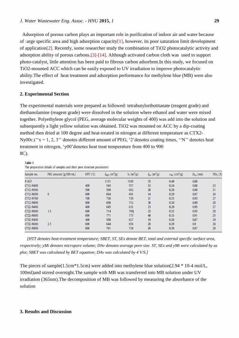
The experimental materials were prepared as followed: tetrabutylorthotitanate (reagent grade) and
diethanolamine (reagent grade) were dissolved in the solution where ethanol and water were mixed
together. Polyethylene glycol (PEG, average molecular weights of 400) was add into the solution and
subsequently a light yellow solution was obtained. TiO2 was mounted on ACC by a dip-coating
method then dried at 100 degree and heat-treated in nitrogen at different temperature as CTX2-
Ny00c.(‘‘x = 1, 2, 3’’ denotes different amount of PEG, ‘2’denotes coating times, ‘‘N’’ denotes heat
treatment in nitrogen, ‘y00’denotes heat treat temperature from 400 to 900
8C).
[HTT denotes heat-treatment temperature; SBET, ST, SEx denote BET, total and external specific surface area,
respectively; yMi denotes micropore volume; DAv denotes average pore size. ST, SEx and yMi were calculated by as
plot; SBET was calculated by BET equation; DAv was calculated by 4 V/S.]
The pieces of sample(1.5cm*1.5cm) were added into methylene blue solution(2.94 * 10-4 mol/L,
100ml)and stirred overnight.The sample with MB was transferred into MB solution under UV
irradiation (365nm).The decomposition of MB was followed by measuring the absorbance of the
solution
3. Results and Discussion
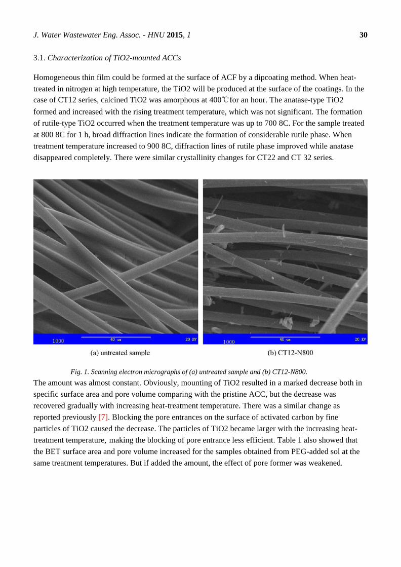
J. Water Wastewater Eng. Assoc. - HNU 2015, 1 30
3.1. Characterization of TiO2-mounted ACCs
Homogeneous thin film could be formed at the surface of ACF by a dipcoating method. When heat-
treated in nitrogen at high temperature, the TiO2 will be produced at the surface of the coatings. In the
case of CT12 series, calcined TiO2 was amorphous at 400℃for an hour. The anatase-type TiO2
formed and increased with the rising treatment temperature, which was not significant. The formation
of rutile-type TiO2 occurred when the treatment temperature was up to 700 8C. For the sample treated
at 800 8C for 1 h, broad diffraction lines indicate the formation of considerable rutile phase. When
treatment temperature increased to 900 8C, diffraction lines of rutile phase improved while anatase
disappeared completely. There were similar crystallinity changes for CT22 and CT 32 series.
Fig. 1. Scanning electron micrographs of (a) untreated sample and (b) CT12-N800.
The amount was almost constant. Obviously, mounting of TiO2 resulted in a marked decrease both in
specific surface area and pore volume comparing with the pristine ACC, but the decrease was
recovered gradually with increasing heat-treatment temperature. There was a similar change as
reported previously [7]. Blocking the pore entrances on the surface of activated carbon by fine
particles of TiO2 caused the decrease. The particles of TiO2 became larger with the increasing heat-
treatment temperature, making the blocking of pore entrance less efficient. Table 1 also showed that
the BET surface area and pore volume increased for the samples obtained from PEG-added sol at the
same treatment temperatures. But if added the amount, the effect of pore former was weakened.

J. Water Wastewater Eng. Assoc. - HNU 2015, 1 31
Fig. 2. XRD patterns of (a) CT12 series, (b) CT22 series and (c) CT32 series.
3.2. Adsorption and photocatalytic activities of TiO2-mounted ACCs
TiO2-mounted ACC samples were dispersed into a higher concentration of MB solution in the dark
overnight for adsorption firstly. MB can pass through TiO2 coating and reach the pores of ACF.
Because of the abundant porosities of ACFs, the samples exhibited high adsorption capacities. For
three series of samples, different treatment temperatures resulted in different pore structures, leading to
different adsorption amounts for MB. The capacities increased with the increasing treatment
temperature, corresponding to the changes of pore volume and specific surface area. Different interface
characteristics might create different capacities. Comparing CT12 series and CT22 series, the latter
series possessed somewhat lower capacities although higher surface areas and pore volumes. PEG by
pyrolysis produced pores in the TiO2. During the heat process in nitrogen, a little amount of carbon
would be remained and thus coat the surface of TiO2. Coated carbon can hinder the growth of the
anatase crystal and prevent the transformation to rutile-type [5–8]. But these effects were less efficient

J. Water Wastewater Eng. Assoc. - HNU 2015, 1 32
in very little amount of carbon and it can be confirmed in XRD patterns. It can be seen from Fig. 3 that
it was similar when comparing CT32 series and CT22 series.
Fig. 3. Adsorption capacity of samples for MB (2.94 _ 10_4 mol/L).
After adsorption equilibrium was reached, the treated sample with a low concentration was handled
under UV irradiation for photocatalytic reactions. In the beginning process, MB concentrations in the
solution changed smoothly, even increased for some samples. Later, MB concentrations leveled off
then decreased linearly. It is seen from Fig. 4. It was supposed that TiO2-mounted firstly decomposed
MB pre-adsorbed in ACF in the beginning. Then, some MB could desorb and enter into solution
because of higher adsorption amount and lower decomposition rate. Obviously, the adsorption capacity
might influence the beginning stage. The higher the adsorption capacity, the more distinct the convex
plot in the beginning was.
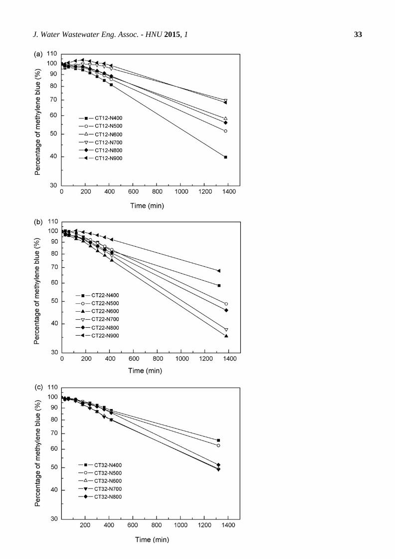
J. Water Wastewater Eng. Assoc. - HNU 2015, 1 33

J. Water Wastewater Eng. Assoc. - HNU 2015, 1 34
Fig. 4. Changes in MB solution with irradiation time for (a) CT12 series, (b) CT22
series and (c) CT32 series.
The rate constants for MB decomposition reaction were determined from linear relation of logarithm
of relative concentration of MB (Fig. 5). Although they had similar crystallinities at the same treatment
conditions, the changes of rate constants upon treatment temperature were different. Their pore
structure and interface characteristics might be the reason. The rate constants decreased with treatment
temperature in CT12 series. This changing trend was opposite to the plot of CT12 series in Fig. 3.
However, the changes were consistent with the singular point of CT12-N800 in both plots. The more
the adsorptive amount, the more the amount to be decomposed was. And in this moment, the effect of
crystallinity was not so significant.
Fig. 5. Rate constants for MB decomposition versus heat-treatment temperatures
As for CT22 and CT32 series, PEG endowed pores and a bit of carbon in TiO2 through pyrolysis,
resulting in different photocatalytic activities. In the case of CT22-N400 and CT32-N400, carbon
residues might cover TiO2 and affect the irradiation, which can lead to lower decomposition rate.
Added more PEG can generate more carbon, thus the rate constant of CT32-N400 was lower than that
of CT22-N400. For the same reason, the plot of CT32 series was at lower position as shown in Fig. 5.
However, pores produced in TiO2 favored diffusion and mass transfer, making the effect of

J. Water Wastewater Eng. Assoc. - HNU 2015, 1 35
crystallinity emerge. It was reported that the rate constant of TiO2 for MB decomposition increased up
to a maximum at around 700 8C and then decreased with increasing temperature, suggesting a strong
dependence of rate constant on crystallinity of anatase phase.[15] There was a similar trend for the
TiO2 only as porous structure mounted on ACCs. The present results showed that the photocatalytic
activity of TiO2 mounted on ACCs depended strongly not only on the content and crystallinity of the
anatase phase but also on the pore structure. Therefore, both the adsorption capacity and the
photocatalytic activity of porous TiO2 mounted on ACC could be improved by annealing at a high
temperature. It can be obtained that an optimal sample for the present condition is CT22-N700.
Conclusions
TiO2 can be mounted on ACC through dip-coating method and subsequently annealed in nitrogen
atmosphere, which result in a remarkable decrease in specific surface area and pore volume comparing
with the pristine ACC. With the increase heat-treatment temperature, the pristine ACC can recover
eventually. crystallinity of TiO2 and its pore structure can be modified through treatment condition and
adding different amount of PEG respectively. The result showed that both pore structure of hybrids
and crystallinity of TiO2 as well as the carbon residue had effects on their adsorptive and
photocatalytic performances.For the present condition, an optimal sample was CT22-N700which
showed almost the highest adsorption capacity and photocatalytic activity.In the dark, the adsorption
occurs, while under the UV light both adsorption and photocatalysis processes are expected to occur.
Acknowledgments
The authors would like to appreciate the financial support of National High Technology Research and
Development Program of China (863 Program) (No. 2007AA061405).
Author Contribution
Abstract, Key Word, Introduction-Yifan Yang
Experimental section-Yue Wang
Results and Discussion, Conclusion-Tianpeng Su
References and Notes
[1] Z.H. Huang, F.Y. Kang, Y.P. Zheng, J.B. Yang, K.M. Liang, Carbon 40 (2002) 1363.
[2] D.F. Ollis, H. Al-Ekabi (Eds.), Photocatalytic Purification and Treatment of Water
and Air, Elsevier, Amsterdam, 1993.

J. Water Wastewater Eng. Assoc. - HNU 2015, 1 36
[3] Z.H. Huang, D.P. Xu, F.Y. Kang, J.M. Hao, New Carbon Mater. 19 (2004) 229.
[4] T. Tsumura, N. Kojitani, H. Umemura, M. Toyoda, M. Inagaki, Appl. Surf. Sci. 196
(2002) 429.
[5] T. Tsumura, N. Kojitani, I. Izumi, N. Iwashita, M. Toyoda, M. Inagaki, J. Mater. Chem.
12 (2002) 1391.
[6] B. Tryba, T. Tsumura, M. Janus, A.W. Morawski, M. Inagaki, Appl. Catal. B 50 (2004)
177.
[7] M. Inagaki, Y. Hirose, T. Matsunag, T. Tsumur, M. Toyoda, Carbon 41 (2003) 2619.
[8] L. Zhang, P. Liu, Z. Su, J. Mol. Catal. A 248 (2006) 189.
[9] H. Uchida, S. Itoh, H. Yoneyama, Chem. Lett. (1993) 1995.
[10] H. Yoneyama, T. Torimoto, Catal. Today 58 (2000) 133.
[11] M. Toyoda, Y. Nanbu, T. Kitob, M. Himno, M. Inagaki, Desalination 159 (2003) 273.
[12] B. Tryba, A.W. Morawski, M. Inagaki, Appl. Catal. B 41 (2003) 427.
[13] B. Tryba, A.W. Morawski, M. Inagaki, Appl. Catal. B 46 (2003) 203.
[14] D.P. Xu, Z.H. Huang, F.Y. Kang, et al. J. Wuhan Univ. Tech. Mater. Sci. Ed. 22 (2007)
450.
[15] M. Inagaki, R. Nonaka, B. Tryba, A.W. Morawski, Chemosphere 64 (2006) 437.

J. Water Wastewater Eng. Assoc. - HNU 2015, 1 37
J. Water Wastewater Eng. Assoc.- HNU, 2015, 1, 37-43.
English for
Water and Wastewater
Engineering Major FALL 2015
http://www.minnwater.com/research/?p=149
Article
Improving Electro-adsorption Ability of Activated Carbon Electrodes
through Titanium Modification
Yujia Zhai 1,
*, Lu Zhang 2,†
, Yanbing Liu 3,†
1 Department of Water and Wastewater Engineering,Hunan University: [email protected] 2 Department of Water and Wastewater Engineering,Hunan University:[email protected] 3 Department of Water and Wastewater Engineering,Hunan University:[email protected]
† These authors contributed equally to this work.
Academic Editor: H.L. Tang
Received: 5 November 2015 / Accepted: 13 November 2015 / Published: 18 November 2015
Abstract: The capacity deionization of activated carbon electrodes was enhanced by
modification of appling mental alkoxides of titanium, silicon, aluminum and zirconium on
the surface of activated carbon cloth.The surface property of activated carbon cloth was
deduced from surface analysis results using SEM, XRD, XPS. Titanium was effective to
decrease physical adsorption of NACL and to increase electrical adsorption.
Keywords:Capacitive deionization (CDI); Activated carbon cloth (ACC); Titania
modification
1. Introduction
Water is significant for life as well as regarded as fundamental sources for industries and
agriculture[1]where various electrolytes are highly dissolved[2,3]. The dissolved amount of ions is
crucial for its applications. For instance, the various dissolved electrolytes determined different
treatment processes in wastewater and sewage treatment plants as well as in other industries such as
nuclear power plants[4,5] and semiconductor manufacturing processes[6,7] which help to improve
CE 06015
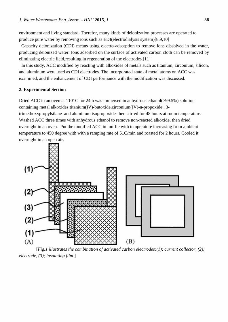
J. Water Wastewater Eng. Assoc. - HNU 2015, 1 38
environment and living standard. Therefor, many kinds of deionization processes are operated to
produce pure water by removing ions such as EDI(electrodialysis system)[8,9,10]
Capacity deionization (CDI) means using electro-adsorption to remove ions dissolved in the water,
producing deionized water. Ions adsorbed on the surface of activated carbon cloth can be removed by
eliminating electric field,resulting in regeneration of the electrodes.[11]
In this study, ACC modified by reacting with alkoxides of metals such as titanium, zirconium, silicon,
and aluminum were used as CDI electrodes. The incorporated state of metal atoms on ACC was
examined, and the enhancement of CDI performance with the modification was discussed.
2. Experimental Section
Dried ACC in an oven at 1101C for 24 h was immersed in anhydrous ethanol(>99.5%) solution
containing metal alkoxides:titanium(IV)-butoxide,zirconium(IV)-n-propoxide , 3-
trimethoxypropylsilane and aluminum isopropoxide,then stirred for 48 hours at room temperature.
Washed ACC three times with anhydrous ethanol to remove non-reacted alkoxide, then dried
overnight in an oven. Put the modified ACC in muffle with temperature increasing from ambient
temperature to 450 degree with with a ramping rate of 51C/min and roasted for 2 hours. Cooled it
overnight in an open air.
[Fig.1 illustrates the combination of activated carbon electrodes:(1); current collector, (2);
electrode, (3); insulating film.]

J. Water Wastewater Eng. Assoc. - HNU 2015, 1 39
[Fig.2 shows a testing apparatus for CDI performance.]
An assembled CDI cell was put in a Pyrex glass reactor containing 500mL sodium chloride, adjusted
the concentration to 0.1mM,The solution in the reactor was stirred by a teflon impeller with 400 rpm to
reduce mass transfer limitation.The concentration change of the solution due to ion adsorption was
measured using an ion conductivity meter, recorded the variation of concentration at every minute.
3. Results and Discussion
3.1. Characterization of modified ACC
TG results in airflow provide the incorporated amounts of metal as metal oxides.The incorporated
amounts of metal on the ACC were varied with the metal elements, although metal alkoxide
concentrations of prepared solutions for the Ti(0.81)/ACC, Zr(0.38)/ACC, Si(0.28)/ACC and
Al(0.20)/ACC were the same as mole. Since metal atoms were fixed on the ACC surface through the
reaction between their alkoxide molecules and surface hydroxyl groups, the difference in the reactivity
of alkoxide species brought about the difference in the incorporated amounts. The small decrease in
the BET surface area by the modification indicated that most modified atoms reacted with surface
functional groups and were located on the surface without blocking pores of the ACC.
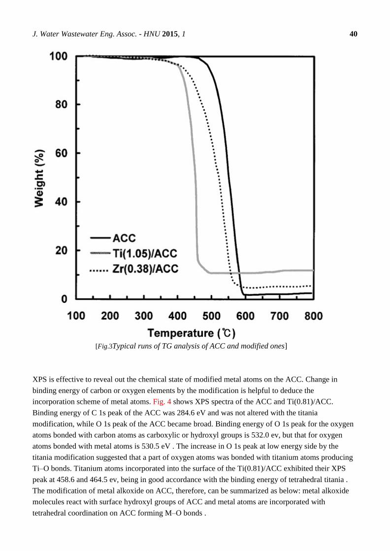
J. Water Wastewater Eng. Assoc. - HNU 2015, 1 40
[Fig.3Typical runs of TG analysis of ACC and modified ones]
XPS is effective to reveal out the chemical state of modified metal atoms on the ACC. Change in
binding energy of carbon or oxygen elements by the modification is helpful to deduce the
incorporation scheme of metal atoms. Fig. 4 shows XPS spectra of the ACC and Ti(0.81)/ACC.
Binding energy of C 1s peak of the ACC was 284.6 eV and was not altered with the titania
modification, while O 1s peak of the ACC became broad. Binding energy of O 1s peak for the oxygen
atoms bonded with carbon atoms as carboxylic or hydroxyl groups is 532.0 ev, but that for oxygen
atoms bonded with metal atoms is 530.5 eV . The increase in O 1s peak at low energy side by the
titania modification suggested that a part of oxygen atoms was bonded with titanium atoms producing
Ti–O bonds. Titanium atoms incorporated into the surface of the Ti(0.81)/ACC exhibited their XPS
peak at 458.6 and 464.5 ev, being in good accordance with the binding energy of tetrahedral titania .
The modification of metal alkoxide on ACC, therefore, can be summarized as below: metal alkoxide
molecules react with surface hydroxyl groups of ACC and metal atoms are incorporated with
tetrahedral coordination on ACC forming M–O bonds .
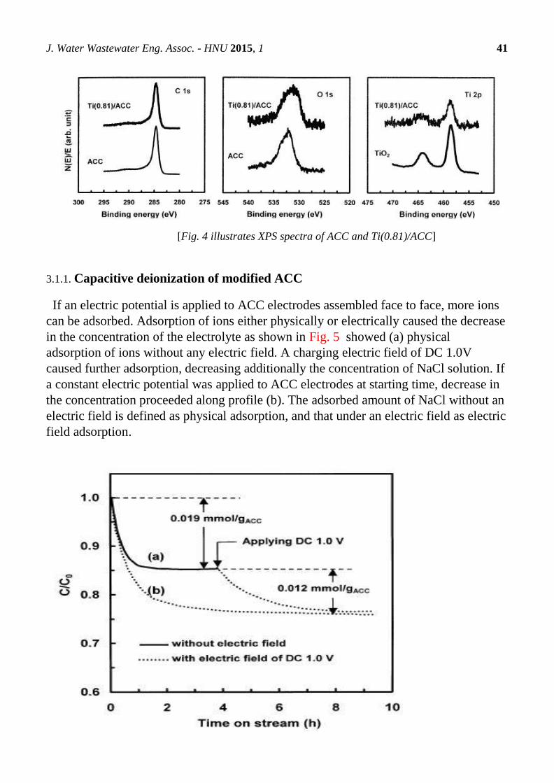
J. Water Wastewater Eng. Assoc. - HNU 2015, 1 41
[Fig. 4 illustrates XPS spectra of ACC and Ti(0.81)/ACC]
3.1.1. Capacitive deionization of modified ACC
If an electric potential is applied to ACC electrodes assembled face to face, more ions
can be adsorbed. Adsorption of ions either physically or electrically caused the decrease
in the concentration of the electrolyte as shown in Fig. 5 showed (a) physical
adsorption of ions without any electric field. A charging electric field of DC 1.0V
caused further adsorption, decreasing additionally the concentration of NaCl solution. If
a constant electric potential was applied to ACC electrodes at starting time, decrease in
the concentration proceeded along profile (b). The adsorbed amount of NaCl without an
electric field is defined as physical adsorption, and that under an electric field as electric
field adsorption.

J. Water Wastewater Eng. Assoc. - HNU 2015, 1 42
[Fig5. Adsorption profiles of NaCl on ACC electrode without (a) and with (b) electric
field of DC 1.0V at 251C. [NaCl]0=0.1mM.]
Fig. 6 shows adsorption of NaCl on the Ti(1.05)/ACC comparing with the ACC itself. Titania
modification resulted in a considerable decrease in physical adsorption, but a significant increase in
electric field adsorption. Reaction of titanium but oxide molecules with polar groups of the ACC
reduced the number of polar groups, resulting in a considerable decrease in the physical adsorption. In
addition, titanium atoms incorporated on the ACC surface worked as adsorption sites when an electric
field was applied, enhancing significantly its electric field adsorption.
[Fig. 6. Adsorption profiles of NaCl on ACC and Ti(1.05)/ACC electrodes at 251C.
[NaCl]0=0.1mM.]
Conclusions
Titania on the surface of ACC can result in considerable reduction of physical adsorption of NaCl,
while increase its electrical adsorption due to enormous adsorption sites for ions under electric field.
Titanium modification is effective to improve electro-adsorption ability of CDI .
4.
Acknowledgments
This work was supported by the BK21 Project (EI238) and Hankook Jungsoo Industries Co., Ltd.

J. Water Wastewater Eng. Assoc. - HNU 2015, 1 43
Author Contribution
Abstract, Key Word, Introduction-Yujia Zhai
Experimental section-Lu Zhang
Results and Discussion, Conclusion-Yanbing Liu
References and Notes
[1] Parsons SA. The effect of domestic ion-exchange water softeners on the microbiological quality of drinking
water.Water Res 2000;34:2369–75.
[2] Whitehead P. Ultra-pure water for ion chromatography. J Chromatogr 1997;A 770:115–8.
[3] Bland LA, Arnow PM, Arduino MJ, McAllister SK. Potentialhazards of deionization systems used for water
purification in hemodialysis. Artif Organs 1996;20:2–7.
[4] Matsuo T, Nishi T. Activated carbon filter treatment of laundry waste water in nuclear power plants and filter
recovery by heating in vacuum. Carbon 2000;38:709–14.
[5] Bondoux G, Jandik P, Jones WR. New approach to the analysis of low levels of anions in water. J Chromatogr
1992;602:79–88.
[6] Vanatta LE, Coleman DE, Slingsby RW. Low-level calibration study for a new ion chromatographic column
to determine borate in deionized water. J Chromatogr A 1999;850:107–17.
[7] Takeda K, Watanabe S, Naka H, Okuzaki J, Fujimoto T. Determination of ultra-trace impurities in
semiconductorgrade water and chemicals by inductively coupled plasma mass spectrometry following a concentration
step by boiling with mannitol. Anal Chim Acta 1998;377:47–52.
[8] Spiegler KS, El-Sayed YM. The energetics of desalination processes. Desalination 2001;134:109–28.
[9] Perez RV, Rodriguez ML, MengualJAI. Characterizing an electrodialysis reversal pilot plant.
Desalination 2001;137:199–206.
[10] SpiegelEF, Thompson PM, Helden DJ, Doan HV, Gaspar DJ, Zanapalidou H. Investigation of an
electrodeionization system for the removalof low concentrations of ammonium ions. Desalination
1999;123:85–92.
[11] Farmer JC, Fix DV, Mack GV, Pekala RW, Poco JF. Capacitive deionization of NH4ClO4
solutions with carbon aerogel electrodes. J. Appl Electrochem 1996;26:1007–18.
J. Water Wastewater Eng. Assoc. - HNU 2015, 1 44
J. Water Wastewater Eng. Assoc.- HNU, 2015, 1, 44-51.
English for
Water and Wastewater
Engineering Major FALL 2015
http://www.minnwater.com/research/?p=149
Article
A Review of electrosorption selectivity of ions using activated
carbon electrodes in capacitive deionization
Zheng Li 1,
*, Yishuang Wang 2,†
, Jinyan Peng2,†
1 Department of Water Engineering and Science, College of Civil Engineering, Hunan University,
Changsha, Hunan 410082, China; E-Mail: [email protected] 2
Department of Water Engineering and Science, College of Civil Engineering, Hunan University,
Changsha, Hunan 410082, China; E-Mails: [email protected]; [email protected]
† These authors contributed equally to this work.
* Department of Water Engineering and Science, College of Civil Engineering, Hunan University,
Changsha, Hunan 410082, China; E-Mail: [email protected];
Tel.: +86-183-9088-7630.
Academic Editor: H.L. Tang
Received: 5 November 2015 / Accepted: 13 November 2015 / Published: 18 November 2015
Abstract: Capacitive deionization (CDI) is known for its cost-effective environmentally
friendly advantages in waste water treatment. The activated carbon electrode which
consists the core of capacitive deionization was synthesized by powder on low pressure and
low temperature thermal chemical vapor deposition. Cyclic voltammetry and
electrosorption experiments were two normal ways to systematically study the
electrochemical properties of carbon film. Since the performance of activated carbon
electrode is often affected by ionic charge and hydrated radius. Several experiments were
conducted to study the ion removal capacity and selectivity. Normally cations with higher
valence to screen the surface charge were more effectively removed than monovalent
cations. And for cations with same charge, the one with smaller hydrated radius would be
more effectively removed.
Keywords: Capacitive deionization; Electrosorption; Activated carbon; Cyclic
voltammetry; Valence; Hydrated radius
CE 06015
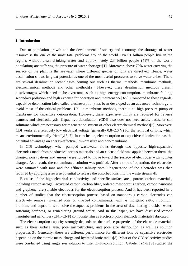
J. Water Wastewater Eng. Assoc. - HNU 2015, 1 45
1. Introduction
Due to population growth and the development of society and economy, the shortage of water
resource is the one of the most fatal problems around the world. Over 1 billion people live in the
regions without clean drinking water and approximately 2.3 billion people (41% of the world
population) are suffering the pressure of water shortages[1]. Moreover, above 70% water covering the
surface of the plant is the seawater where different species of ions are dissolved. Hence, water
desalination shows its great potential as one of the most useful processes to solve water crises. There
are several desalination technologies coming out such as thermal methods, membrane methods,
electrochemical methods and other methods[2]. However, these desalination methods present
disadvantages which need to be overcome, such as high energy consumption, membrane fouling,
secondary pollution and high expense for operation and maintenance[3-5]. Compared to those regards,
capacitive deionization (also called electrosorption) has been developed as an advanced technology to
avoid most of the critical problems. Unlike membrane methods, there is no high-pressure pump or
membrane for capacitive deionization. However, these expensive things are required for reverse
osmosis and electrodialysis. Capacitive deionization (CDI) also does not need acids, bases, or salt
solutions which are necessary for regeneration system of other electrochemical methods[6]. Moreover,
CDI works at a relatively low electrical voltage (generally 0.8–2.0 V) for the removal of ions, which
means environmentally friendly[5, 7]. In conclusion, electrosorption or capacitive deionization has the
potential advantage on energy-effective, low-pressure and non-membrane.
In CDI technology, when pumped wastewater flows through two opposite high-capacitive
electrodes made from conductive porous materials and an electric field was applied between them, the
charged ions (cations and anions) were forced to move toward the surface of electrodes with counter
charges. As a result, the contaminated solution was purified. After a time of operation, the electrodes
were saturated with ions and the effluent salinity rises. Regeneration of the electrodes was then
required by applying a reverse potential to release the adsorbed ions into the waste stream[4].
Because of the high electrical conductivity and specific surface area, porous carbon materials,
including carbon aerogel, activated carbon, carbon fiber, ordered mesoporous carbon, carbon nanotube,
and graphene, are suitable electrodes for the electrosorption process. And it has been reported in a
number of studies that the electrosorption process based on nanoporous carbon electrodes can
effectively remove unwanted ions or charged contaminants, such as inorganic salts, chromium,
uranium, and cupric ions to solve the aqueous problems in the area of desalinating brackish water,
softening hardness, or remediating ground water. And in this paper, we have discussed carbon
nanotube and nanofiber (CNT-CNF) composite film as electrosorption electrode materials fabricated.
The electrosorption capacity strongly depends on the surface properties of the electrode materials
such as their surface area, pore microstructure, and pore size distribution as well as solution
properties[3]. Generally, these are different performance for different ions by capacitive electrodes
depending on the atomic mass, charge and hydrated ionic radius[8]. Most of the CDI selectivity studies
were conducted using single ion solution to infer multi-ion solution. Gabelich et al.[9] studied the

J. Water Wastewater Eng. Assoc. - HNU 2015, 1 46
electrosorption behavior of carbon aerogel electrodes in different solutions and reported that ion
selectivity was based on the hydrated size of the ions and that monovalent ions were preferentially
removed from feed solution over multivalent ions. The ion selectivity of CDI electrodes has not been
clearly elucidated, especially in complex multi-ionic solutions that reflect the reality conditions such as
brackish groundwater purification.
2. Experimental Section
2.1. Manufacture of activated carbon electrodes
The carbon sheet electrode used in deionization was produced by mixed activated carbon powder
(Filtrasorb 400, Chemviron Carbon Inc.) and polyvinylidene fluoride (PVDF, M.W.=534,000, Sigma-
Aldrich) polymer binder in an N, N-Dimethylacetamide (DMAc, 99%, Alfa Aesar) solution[10]. In
PVDF polymer was 10 wt.% of the carbon electrode. A titanium plate base was painted with the
carbon mud and then dried in a 120 °C oven for 2 h to form a carbon film. The carbon film later would
be placed in an 80 °C vacuum oven for 2 h, which would get rid of all organic materials.
2.2. Characteristic measurements of Electrodes
The Brunauer-Emmett-Teller (BET) method from the nitrogen adsorption/desorption data at a
relative pressure of p/p0=0.99 was mainly used to measure the pore size distribution and specific
surface area with the help of porosity analyzer (ASPS 2020, Micromeritics Inc.). And the shape of
surface of CNTs–CNFs film was examined by JEOLJSM-LV5610 scanning electron microscopy
(SEM), operating at 10 kV[11].
2.3. Cyclic voltammetry experiments
In room temperature, Voltammetry measurements were performed by using a three-electrode-cell
potentiostat (CHI627D, CH Instruments, Inc.) under 1 mV/s scan rate in the potential range of +0.6 to -
0.4 V [10]. ne small piece of activated carbon electrode, one big piece of activated carbon electrode,
and one Ag/AgCl electrode (BAS model RE-1, Bioanalytical Systems, Inc.) were respectively set to
be the working electrode, the counter electrode, and the reference electrode. The capacity is calculated
by the following formula:
In this formula, C means the specific capacity (F/g). i and v separately mean the current density (A)
and scan rate (V/s), m means the mass of the activated carbon electrode (g).
2.4. Equilibrium experiments of electrosorption
Electrosorption experiments were carried out in a circulatory system which was shown in Fig. 1. A
electrosorption unit cell consisted of a pair of activated carbon film with a 2.0 mm gap, a peristaltic
pum (MP-1000, EYELA) with a 10-mL/min Velocity of flow and a 50-mL total solution volume , a
conductivity meter (SC-2300, Suntex) put in the end of the cell, a potentiostat (CHI 627D) and a ion
chromatography (883-basic IC plus, Metrohm) with a cation separation column (Metrosep C 4-100/4.0)
became the main equipment in the equilibrium experiment. The size of carbon film is 70 mm × 70 ×
0.38 mm with a weight of about 1.4 g. When the conductivity hardly changes, concentration measured
mv
i C
(1)

J. Water Wastewater Eng. Assoc. - HNU 2015, 1 47
by ion chromatography will be noted down for the final record. Pure analytic sodium chloride (NaCl,
Merck), potassium chloride ( KCl , Merck), magnesium chloride ( 2MgCl , Merck), and calcium
chloride ( 2CaCl , Merck) were placed in the electrolyte solutions.
Ionic hydrated radius and charge, as already mentioned, are critical to effect of electrosorption on
the electrode surface. So the main purpose of experiments is to clarify the electrosorption preference of
cations in a competitive multi-ionic solution. Cations of different charges and hydrated radii are
assumed to compete with each other to screen the surface charge of carbon electrodes. Since the
concentrations can be measured by ion chromatography, the change will be calculated the
electrosorption capacity for each cation on a molar basis can be obtained. Experiments will be repeated
several times to ensure accuracy.
Fig. 1. Schematic diagram of the electrosorption setup of CDI
3. Results and Discussion
3.1. Electrochemical characteristics
To investigate the effects of ion properties on the capacitive characteristic, the studied ions were
monovalent +Na and +K , and divalent 2Mg and +2Ca cations[8]. The order of their hydrated radii
is as follows: +K (3.31 Å)b +Na (3.58 Å)b +2Ca (4.12 Å)b 2Mg (4.28 Å). All electrolyte solutions
had a common anion ( Cl ) with a hydrated radii of 3.32 Å.
Cyclic voltammetry is an important method to evaluate the capacitive characteristics of carbon
electrodes for electrosorption. Figure. 3 shows the cyclic voltammograms obtained at a scan rate of 1
mV/s for 10 mM 1:1 (NaCl and KCl), and 5 mM 2:1( 2MgCl and 2CaCl ) electrolyte solutions.
Obviously, there was no evident oxidation/reduction peak in cyclic voltammetry curves, ensuing that
ions electroadsorbed on the electrode surface was caused by purely electrostatic interactions rather
than Faradic reaction[12]. The specific capacitance can be considered as a result of EDL formation
within the carbon electrode as well as the double-layer capacitance. In addition, the shape of cyclic
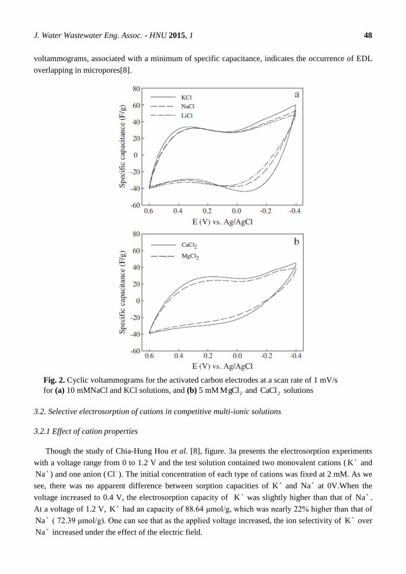
J. Water Wastewater Eng. Assoc. - HNU 2015, 1 48
voltammograms, associated with a minimum of specific capacitance, indicates the occurrence of EDL
overlapping in micropores[8].
Fig. 2. Cyclic voltammograms for the activated carbon electrodes at a scan rate of 1 mV/s
for (a) 10 mMNaCl and KCl solutions, and (b) 5 mM 2MgCl and 2CaCl solutions
3.2. Selective electrosorption of cations in competitive multi-ionic solutions
3.2.1 Effect of cation properties
Though the study of Chia-Hung Hou et al. [8], figure. 3a presents the electrosorption experiments
with a voltage range from 0 to 1.2 V and the test solution contained two monovalent cations ( +K and +Na ) and one anion ( -Cl ). The initial concentration of each type of cations was fixed at 2 mM. As we
see, there was no apparent difference between sorption capacities of +K and +Na at 0V.When the
voltage increased to 0.4 V, the electrosorption capacity of +K was slightly higher than that of +Na .
At a voltage of 1.2 V, +K had an capacity of 88.64 μmol/g, which was nearly 22% higher than that of +Na ( 72.39 μmol/g). One can see that as the applied voltage increased, the ion selectivity of +K over +Na increased under the effect of the electric field.
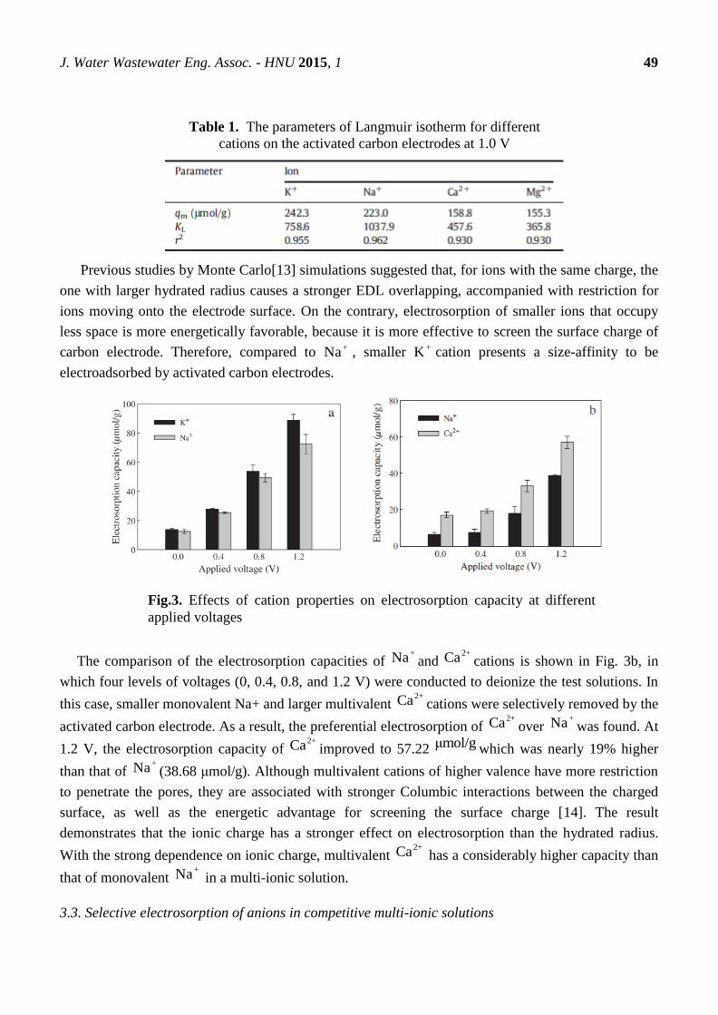
J. Water Wastewater Eng. Assoc. - HNU 2015, 1 49
Previous studies by Monte Carlo[13] simulations suggested that, for ions with the same charge, the
one with larger hydrated radius causes a stronger EDL overlapping, accompanied with restriction for
ions moving onto the electrode surface. On the contrary, electrosorption of smaller ions that occupy
less space is more energetically favorable, because it is more effective to screen the surface charge of
carbon electrode. Therefore, compared to +Na , smaller +K cation presents a size-affinity to be
electroadsorbed by activated carbon electrodes.
The comparison of the electrosorption capacities of +Na and
2+Ca cations is shown in Fig. 3b, in
which four levels of voltages (0, 0.4, 0.8, and 1.2 V) were conducted to deionize the test solutions. In
this case, smaller monovalent Na+ and larger multivalent 2+Ca cations were selectively removed by the
activated carbon electrode. As a result, the preferential electrosorption of 2+Ca over
+Na was found. At
1.2 V, the electrosorption capacity of 2+Ca improved to 57.22 μmol/g which was nearly 19% higher
than that of +Na (38.68 μmol/g). Although multivalent cations of higher valence have more restriction
to penetrate the pores, they are associated with stronger Columbic interactions between the charged
surface, as well as the energetic advantage for screening the surface charge [14]. The result
demonstrates that the ionic charge has a stronger effect on electrosorption than the hydrated radius.
With the strong dependence on ionic charge, multivalent 2+Ca has a considerably higher capacity than
that of monovalent +Na in a multi-ionic solution.
3.3. Selective electrosorption of anions in competitive multi-ionic solutions
Table 1. The parameters of Langmuir isotherm for different
cations on the activated carbon electrodes at 1.0 V
Fig.3. Effects of cation properties on electrosorption capacity at different
applied voltages

J. Water Wastewater Eng. Assoc. - HNU 2015, 1 50
3.3.1 Effect of cation properties
Though the study of Likun Pan et al. [9], the effects of ion charge, size and mass on electrosorption
capacity were investigated by several electrosorption experiments in NaCl, 3NaNO , and
2 4Na SO solutions, respectively. Table 2 shows the anion properties including charge, ionic radius and
hydrated radius of different anions. The initial concentration of all the selective solutions was fixed at
0.001 mmol/l.
The applied voltage was 1.2 V and the flow rate was 14 ml/l. The electrosorption capacity (by
µmol/g) is defined as adsorbed ion amounts per gram of the electrodes.
The capacitances of CNT–CNF composite film electrodes in different solutions were determined by
ac impedance spectra. Fig.4 shows the electrosorption capacities and the calculated capacitances of
CNT–CNF composite film electrodes in different solutions. The measured electrosorption capacities to
different salt solutions are consistent with the calculated capacitances. It can be seen that, when the
solutions have different anions and the same cation (+Na ), the CNT–CNF composite film electrodes
show better electrosorption capacity for the smaller hydrated anions: Cl > 3NO
> 2
4SO
. It can be
explained by the fact that smaller hydrated anions can more easily enter into the porous network in
CNT–CNF.
4. Conclusions
Fig. 4. Electrosorption capacities of the CNT–CNF composite film electrodes and
electric double-layer capacitance CDL for different solutions
Table 2. Chemical data of test anions
J. Water Wastewater Eng. Assoc. - HNU 2015, 1 51
The results described in this study provide the fundamental effects of ionic charge and hydrated
radius of ions in the process of capacitive deionization. As for alkali- and alkaline-earth cations,
activated carbon films have a preference to adsorb multivalent cations. If cations have the same charge,
the one with smaller hydrated radius would be more likely to be absorbed. As for anions, the
conclusion is consistent with the cations that smaller hydrated anions are preferred in electrosorption.
Author Contributions
Zheng Li wrote section 1. indroduction and section 4. conclusion.
Yishuang Wang wrote section 2. Experimental Section and Abstract
Jinyan Peng wrote section 3. Results and Discussion and key words.
References and Notes
1. J. Yang L. Z., H. Song, Z. Hao. Development of novel MnO2/nanoporous carbon composite
electrodes in capacitive deionization technology. Desalination 2011, 276(2011), 199-206.
2. Li H.;L. Zou;L. Pan Z. S. Using graphene nano-flakes as electrodes to remove ferric ions by
capacitive deionization. SeoPurif Technol 2010, 75(2010), 8-14.
3. Gao Y.;Pan L.;Li H.;Zhang Y.;Zhang Z.;Chen Y., et al. Electrosorption behavior of cations with
carbon nanotubes and carbon nanofibres composite film electrodes. Thin Solid Films 2009,
517(5), 1616-9.
4. Huang C.-H. H. C.-Y. A comparative study of electrosorption selectivity of ions by activated
carbon electrodes in capacitive deionization. Desalination 2013, 314 124–9.
5. Mossad M.;Zou L. A study of the capacitive deionisation performance under various operational
conditions. Journal of hazardous materials 2012, 213-214, 491-7.
6. Gabelich C. J.;T. Tran I. H. S. Electrosorption of inorganic salts from aqueous solution using
carbon aerogels. Environ Sci Technol 2002, 36(2002), 3010-9.
7. Christopherj.Gablich.;Tran T.;Melsuffet A. H. Electrosorption of Inorganic Salts from Aqueous
Solution Using Carbon Aerogels. Environ Sci Technol 2002, 36(2002), 3010-9.
8. Hou.Chia-Hung.;Huang.Cheng-Ye. A comparative study of electrosorption selectivity of ions by
activated carbon electrodes in capacitive deionization. Desalination 2013, 314, 124-9.
9. Pan L.;Wang X.;Gao Y.;Zhang Y.;Chen Y.;Sun Z. Electrosorption of anions with carbon
nanotube and nanofibre composite film electrodes. Desalination 2009, 244 (2009), 139–43.
10. Isabel E.;Schafer. A. Sustainable Water for the Future: Water Recycling, Reuse. Desalination
2010.
11. Y. Kim;Choi J. Enhanced desalination efficiency in capacitive deionization with an ion-selective
membrane. Purif Technol 2010, Sep.(71(2010)), 70-5.
12. Frackowiak E.;Beguin F. Carbon materials for the electrochemical storage of energy in capacitors.
Carbon 2001, 39 (2001), 937–50.
13. Hou. C. H.;Taboada-Serrano. P.;S. Yiacoumi;Tsouris. C. Electrosorption selectivity of ions from
mixtures of electrolytes inside nanopores. J Chem Phys 2008, 129 (2008).

J. Water Wastewater Eng. Assoc. - HNU 2015, 1 52
J. Water Wastewater Eng. Assoc.- HNU, 2015, 1, 52-55.
English for
Water and Wastewater
Engineering Major FALL 2015
http://www.minnwater.com/research/?p=149
Article
Advanced Oxidation Process
Ting Li 1,
*, YongJia Qian 2,†
and ZiYang Wang 2,†
1 [email protected] (Ting Li)
2 [email protected] (YongJia Qian)
2 [email protected] (ZiYang Wang)
Tel.: 18874242800(Ting Li)
Academic Editor: H.L. Tang
Received: 5 November 2015 / Accepted: 13 November 2015 / Published: 18 November 2015
Abstract:Advanced oxidation processes (technology)can put down the pollution from headstream in th
e chemical reaction process, so that it can achieve zero pollution, zero waste emissions. Currently, adv
anced oxidation process are facing with some problems which will hinder the development of its applic
ation in engineering research. This paper focuses on the strong ionization discharge method. The O2,
H2O can be processed into OH* and eaq -at the molecular level after ionization. It can decompos
Organism and Organic compound into 2CO 、 2H O and inorganic salt in 1s;Inorganic pollutant is
oxidized into harmless substance and useful renewable resources;Other OH also be broken down
into 2H O、 2O .
Keywords: advanced oxidation process、strong ionization discharge、hydroxyl radical
1. Introduction
Man is now facing a big environment problem, which even threat to the survival of mankind.So
many scholars put forward “Advanced oxidation process”.Advanced oxidation technology is the
process of producing OH and this process induce a series of OH chain reactions which attack
various pollutants and microorganisms in water until explain it to 2CO 、 2H O and inorganic salt[1,2],
the problem of environment pollution solved radically,zero pollution to the environment and zero
discharge of the Pollutants are realized.Advanced oxidation technology is develops in the increasingly
resulting in a higher efficiency and application efficiency of OH .
CE 06015
J. Water Wastewater Eng. Assoc. - HNU 2015, 1 53
At present, the main way of advanced oxidation process include Chemical oxidation, Fenton
oxidation, Electrochemical oxidation, Photo catalytic oxidation, Photo electric power, Wet air
oxidation, Supercritical water oxidation and ultrasonic oxidation.Therefore, advanced oxidation
technology is highly efficient, fast and complete.It has a good prospect of development.
Of course,some problems still exists in advanced oxidation process.Such as:For the particular
performance ,it cannot be available in a big range.High cost of running for advanced oxidation
technique in utilities.Advanced oxidation process need add High efficiency bubble column reactor、
Rotating packed bed reactor、Fluidized bed photocatalytic reactor and Impinging stream reactor to
maximize treatment efficiency during the application process.When processed hydroxyl radical need
add multitudinous medicament and catalyzer: 2 2H O 、 3O 、 2TiO and 2Fe ,most of this is considers
the 2 2H O as the subject. 2 2H O have problems about security and cost.④Many scholars use UV as a
catalytic measures .Due to the poor penetrating capability of wastewater containing impurities,it`s
difficult to solve the application problem in engineering.Those problems are serious impediment to
development of advanced oxidation process which need to be solved.
2. Experimental Section
2.1 Advanced oxidation characteristics of OH*
Hydroxyl radical (OH*) is one of the most active molecules, as well as one of the most aggressive
chemical substances, which can have various types of chemical reactions with almost all big
molecules, organics and inorganics. What’s more, it has a high reaction rate and the negatively charged
electron affinity.
2.2 Advanced methods to produce OH*
2.2.1. Electromagnetic radiation method
Using an electron accelerator to radiate the water is a new method[3]. Recent studies have successfully
developed a low energy electron accelerator with the energy from 200keV to 800keV. After the high-
energy-electrons going through 20 ~ 40um titanium target window, the average energy of the electron
radiation to the body of water is about 33eV. After the occurrence of radiation , water molecules begin
to have excitation and ionization reaction. Per 100eV will produce 2.7 OH*.The electron accelerator
and its equipment system occupy a large space to exist, what is more, X-ray radiation hazards a lot,
therefore a 2-metre- thick layer of cement should be set outside the system; Because of the large
internal and external pressure, titanium windows are easily damaged. The equation of generating OH*
plasma reaction is:
2H2O+ e → H2O+ + H2O* + 2e
H2O* →H*+ OH*
H2O+ + H2O →H3O+ + OH*
H2O+ e →eaqˉ
2.2.2 Light and catalyst method[5]
There are many N-type semiconductor photocatalysis materials, such as TiO2, ZnO, Fe2O3, CdS, etc.
TiO2 has well light stability. When TiO2 is motivated by more than 3. 2eV light energy, its electrons
J. Water Wastewater Eng. Assoc. - HNU 2015, 1 54
on the full band are excited to jump over the forbidden band into the conduction band, meanwhile, full
band forms a corresponding hole (h+) and a strong electric field will be formed between the
conduction band and the full band. So the electrons can gain sufficient energy from the excitation field.
2.3The process of generating Hydroxyl radical (OH*)
When using the strong electric field ionization discharge method at normal temperature and
pressure[4], in the gap of a plasma reaction chamber, the formation of the streamer generates a
discharge field. When its strength E/n (E is the electric field strength of discharge, n is the gas
concentration, the unit is Td, 1Td = 10e- 17V·cm2) is stronger than 450Td, the average energy that
electrons gain from the electric field is more than 13eV, which can ionized O2 (ionization energy is 12.
5eV), H2O (ionization energy is 12. 6eV). During strong ionization discharge process, when increasing
per 100eV of energy, nearly 2.7 hydrated ions decomposed to OH*. Therefore, strong ionization
discharge is one of the most effective and feasible way to prepare high concentrations of OH.
3. Results and Discussion
3.1Forward oxidation technology
The concept and techniques of advanced oxidation have great significance on the study of advanced
oxidatioin.it can be the guidance to determine the way of studying advanced oxidation . Finally the
define and content of advanced oxidation can be worked out after refering to the idea of
environmental protection . We take H2O and O2 such substances as the raw material to meet the
request of having no pollution in the whole process flow.
As the result of being environmental in chemical reaction ,we need to control the directioin ,velocity
.product of chemical reaction by taking the extremely advanced physical instrument to rearrange
atom outer shell electron.only in this way can we realize the goal of no pollution,no waste effluent and
no byproducts .
Without using catalytic agent,absorbent dissolvant,the process of using and producing can aviod the
trouble of pollution and energy waste.the products should be harmless so as well to the process of
using it.Chemical reactions should be carried out at room temperature and atmospheric pressure,and
energy consumption should be reduced to a minimum.in the following examples,Advanced oxidation
engineering designs are realized by the guidance of the above priciples.Data from a large number of
experiments and industrial tests show that these principles can be fully achieved.
3.2 Resource Reuse hydroxy desulfurization
China is the only country taking coal as the main source of energy in the wole world which also has
the world's largest sulfur dioxide emissions.Annual economic losses of 9.5 billion yuan.Non-pollution
development and utilization of coal resources has become a strategic issue for the sustainable
development of energy in China.The effective method to control the hazard of acid rainis to carry on
the desulfurization of flue gas. Usually after the electric dust collector outside the exhaust gas
J. Water Wastewater Eng. Assoc. - HNU 2015, 1 55
temperature in 120 ℃, you dont have to low the temperature of the flue gas treatment.Only 70% of the
exhaust flue gas to be recycled which is worth more than 10billion yuan.In addition to saving huge
foreign currency, but also to solve the problem of the shortage of sulfur resources in our country.It is
the first time to achieve zero effluent of flue gas desulfurization without using the catalyst or other
materials.This is the ideal method for the treatment of acid rain, and it is a successful example of the
application of advanced oxidation technology.
4. Conclusions
Advanced oxidation process is developed and been renewed to traditional chemistry thought.It`s
to solve environmental pollution from the source,avoid or don`t use material、solvent、 reagent or
catalyzer which are harmful of the ecological environmental;don`t producing the poisonous harmful
chemicals or by-products,seeks to achieve Zero Pollution and Zero Release of waste disposal.Using
2H O、 2O producing OH which has high concentration and high production,disaster of major
marine ecosystems such as Appearance biological invasion and red tide are solved successfully.
Advanced oxidation process will widely used in more areas in the near future,and make a
contribution to the sustainable development of our country.
Author Contributions
Ting Li:Introduction and Conclusions
YongJia Qian:Experimental Section
ZiYang Wang:Results and Discussion
References and Notes
1. Hoigne J.,Bader H.Water Res,.1976;10(2);377
2. Glaze W,H.,Kang J. W.,Chapin D,H.Ozone Sci.&Eng.,1987;9(4)335
3. Cunpu Sun, Jianzhong Zhang, Shaojin Duan.《自由基生物学导论》;1999:31
4. Xiyao Bai,Zhitao Zhang,Mindong Bai,<Nature>,2000;22(3):156
5. Mattews R.W. Water Res.,1990;24(5);653

J. Water Wastewater Eng. Assoc. - HNU 2015, 1 56
J. Water Wastewater Eng. Assoc.- HNU, 2015, 1, 56-61.
English for
Water and Wastewater
Engineering Major FALL 2015
http://www.minnwater.com/research/?p=149
Article
Water distribution
Bowen Xu 1, Jiajun Zhang
2 and Jing Tang
3
1 College of Civil Engineering; E-Mail: [email protected]
2 College of Civil Engineering; E-Mail: [email protected]
3 College of Civil Engineering; E-Mail: [email protected]
Academic Editor: H.L. Tang
Received: 5 November 2015 / Accepted: 13 November 2015 / Published:18 November 2015
Abstract: Rainfall is the most important factor for water resource distribution. Moreover,
Unbalanced water resource distribution is a huge problem, which has some negative
impacts on development of China. Before things get worse, effective measures should be
taken.
Keywords: water resource distribution; standards of water shortage; water vapor; the
windward slope and the leeward slope; air pressure zone; monsoon; water resource
conservation; south-to-north water diversion; salt water desalination.
1. Introduction
1. 1 Global distribution of water resource
Currently, global fresh water resource only account for 2.5% of total water resource. What’s more,
More than 70% of them are frozen in the arctic and Antarctic, which are hard to use by human beings.
Nowadays, we can only make use of water resource from river, lake and groundwater, which is just a
tiny part of the total fresh water. To conclude, water is not a kind of inexhaustible resource.
Water resource distribution of each continent is unbalanced. The annual runoff in Asia is the largest
one, followed by South America, North America, Africa, Europe and Oceania. However, the runoff
per person in the world is approximately 10000 cubic meters and that in Oceania is the most, followed
by South America, North America, Africa, Europe and Asia. Interestingly, in Asia, we can find that the
annual runoff is the most but the runoff per person is the least.
CE 06015
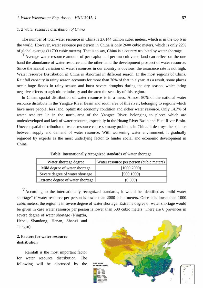
J. Water Wastewater Eng. Assoc. - HNU 2015, 1 57
1. 2 Water resource distribution of China
The number of total water resource in China is 2.6144 trillion cubic meters, which is in the top 6 in
the world. However, water resource per person in China is only 2600 cubic meters, which is only 22%
of global average (11700 cubic meters). That is to say, China is a country troubled by water shortage. [1]
Average water resource amount of per capita and per mu cultivated land can reflect on the one
hand the abundance of water resource and the other hand the development prospect of water resource.
Since the annual variation of water resources in our country is obvious, the assurance rate is not high.
Water resource Distribution in China is abnormal in different season. In the most regions of China,
Rainfall capacity in rainy season accounts for more than 70% of that in a year. As a result, some places
occur huge floods in rainy season and burst severe droughts during the dry season, which bring
negative effects to agriculture industry and threaten the security of this region.
In China, spatial distribution of water resource is in a mess. Almost 80% of the national water
resource distribute in the Yangtze River Basin and south area of this river, belonging to regions which
have more people, less land, optimistic economy condition and richer water resource. Only 14.7% of
water resource lie in the north area of the Yangtze River, belonging to places which are
underdeveloped and lack of water resource, especially in the Huang River Basin and Huai River Basin.
Uneven spatial distribution of water resource cause so many problems in China. It destroys the balance
between supply and demand of water resource. With worsening water environment, it gradually
regarded by experts as the most underlying factor to hinder social and economic development in
China.
Table. Internationally recognized standards of water shortage.
Water shortage degree Water resource per person (cubic meters)
Mild degree of water shortage [1000,2000)
Severe degree of water shortage [500,1000)
Extreme degree of water shortage (0,500)
[2]
According to the internationally recognized standards, it would be identified as “mild water
shortage” if water resource per person is lower than 2000 cubic meters. Once it is lower than 1000
cubic meters, the region is in severe degree of water shortage. Extreme degree of water shortage would
be given in case water resource per person is lower than 500 cubic meters. There are 6 provinces in
severe degree of water shortage (Ningxia,
Hebei, Shandong, Henan, Shanxi and
Jiangsu).
2. Factors for water resource
distribution
Rainfall is the most important factor
for water resource distribution. The
following will be discussed by the
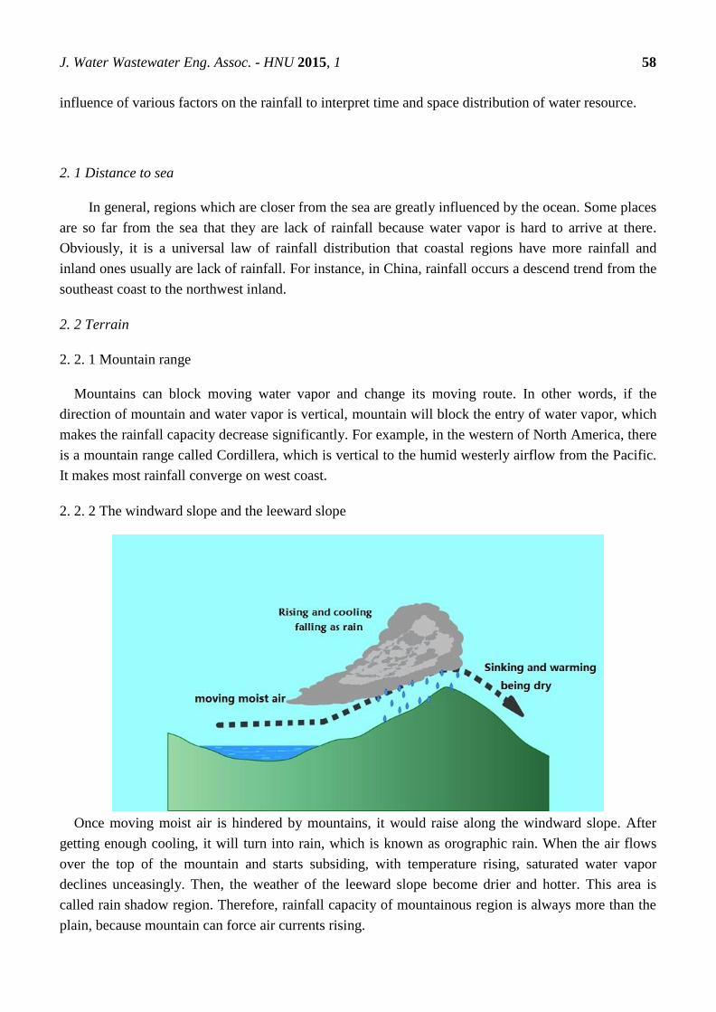
J. Water Wastewater Eng. Assoc. - HNU 2015, 1 58
influence of various factors on the rainfall to interpret time and space distribution of water resource.
2. 1 Distance to sea
In general, regions which are closer from the sea are greatly influenced by the ocean. Some places
are so far from the sea that they are lack of rainfall because water vapor is hard to arrive at there.
Obviously, it is a universal law of rainfall distribution that coastal regions have more rainfall and
inland ones usually are lack of rainfall. For instance, in China, rainfall occurs a descend trend from the
southeast coast to the northwest inland.
2. 2 Terrain
2. 2. 1 Mountain range
Mountains can block moving water vapor and change its moving route. In other words, if the
direction of mountain and water vapor is vertical, mountain will block the entry of water vapor, which
makes the rainfall capacity decrease significantly. For example, in the western of North America, there
is a mountain range called Cordillera, which is vertical to the humid westerly airflow from the Pacific.
It makes most rainfall converge on west coast.
2. 2. 2 The windward slope and the leeward slope
Once moving moist air is hindered by mountains, it would raise along the windward slope. After
getting enough cooling, it will turn into rain, which is known as orographic rain. When the air flows
over the top of the mountain and starts subsiding, with temperature rising, saturated water vapor
declines unceasingly. Then, the weather of the leeward slope become drier and hotter. This area is
called rain shadow region. Therefore, rainfall capacity of mountainous region is always more than the
plain, because mountain can force air currents rising.

J. Water Wastewater Eng. Assoc. - HNU 2015, 1 59
2. 2. 3 Terrain types
Different terrain has different effects on air flow, which means that the distribution of rainfall is also
different. In plain terrain, water vapor brings rich moisture and makes it easier to rain, like the eastern
plain area of China, central Europe, and the Middle East of America. Rainfall capacity in the windward
side of mountain is always more than that in the leeward slope. What’s more, river valley is hotter and
has less rainfall because of its low terrain. Also, in plateau, because of its high terrain, water vapor is
difficult to climb up the plateau surface and falls as rain.
2. 3 Air pressure zone
The sinking air flow is so common
in high-pressure. In the process
of subsidence, the temperature is rising
and saturated water vapor is decreasing. It
means that air is getting drier and it is
hard to turn into rainfall. By contrast, in
the low-pressure area, updraft is
common. The air is easily cooling,
reaching saturation state, and becoming
rainwater, which makes this place
become Rainy Zone. For example, the
equatorial regions are always under the
control of low pressure, making this area
be wet all year round.
2. 4 Monsoon
In the monsoon climate zone, different kinds of monsoons have different impacts on precipitation.
Summer monsoon flows from the sea to the land, bringing so much sea water vapor to the land, which
makes it possible to be rain. Winter monsoon, which is dry and cold, flows from the land to the sea,
making no contribution to the rain. Like the East Asia monsoon region, it has high temperature and
rainy summer, but lacks of rainfall in the winter.
2. 5 Human activities
Human activities influence the precipitation by changing the condition of underlying surface. As
we know, some human activities like afforestation, vegetation restoration and returning farmland to
lake can make the air be wetter, which makes contributions to precipitation. Conversely, things like
deforestation, over grazing, and vegetation destruction will reduce the air humidity, which is not
helpful to rainfall. Additionally, artificial rainfall is an effective method to increase precipitation in the
dry season. Of course, we need not only try to find the dominant factor of rainfall capacity, but also
analyze factors comprehensively.

J. Water Wastewater Eng. Assoc. - HNU 2015, 1 60
3. Measures for water resource distribution
Unbalanced water resource distribution is a huge problem, which has some negative impacts on
development of China. Before things get worse, effective measures should be taken.
3. 1 Water resource conservation
[3]Over the past 30 years, there are so many nations, like Israel, the United States, Britain, Japan and
so on, could keep high GDP continuous growth, with consumption of water resource decreasing. By
contrast, In China, industrial structure is extensive. Majority of companies are energy-inefficient and
high-waste, causing that the water resource waste is very serious, as well as water pollution. As long as
the government pay more attention to water resource conservation and reject to unreasonable methods
of economic development, large number of water resource can be saved, which can mitigate
the consequences of unbalanced water resourced distribution.
3. 2 South-to-north water diversion
The South-to-North Water Diversion Project (SNWDP) is an important strategic project. At present,
the middle and east line of the water diversion project have been in use. However, the west line of
water transfer project is still in the stage of primary research. Once completed, it would be a milestone
for the settlement of water shortage problem, especially in the Northwest China, Inner Mongolia and
Shanxi. The west line of water transfer project will be in the Qinghai Tibet Plateau. What we have to
notice is that the Qinghai Tibet plateau ecological environment is so weak, with serious soil erosion,
frequent earthquakes and high engineering difficulty. The government should pay all attention to the
security and quality of it.
3. 3 Salt water desalination
Salt water desalination is an important measure to solve the shortage of water resource. In recent
decades, due to the development of science and technology, the cost of desalination has been greatly
reduced. Many countries, such as Israel, Saudi Arabia, HK, Maldives and other countries, have already
taken salt water desalination as the main measures to solve the shortage of water resource.
China's coastal provinces and cities in 18000 provinces (autonomous regions) have 11 km
coastline, 6500 islands, the population of these regions accounted for 40% of the country, the total
output value accounted for 60% of the country. Among them, Liaoning, Tianjin, Beijing, Hebei,
Shandong and Northern Jiangsu and their lack of fresh water resource. In these areas, the local, the
nearest sea water desalination and direct use of seawater, not only can solve the problem of water
shortage in the region, but also greatly ease the water shortage in Northwest China, North china. In
addition, Hebei, Tianjin coast is the main source of sea salt in china. We should combine the sea water
desalination with sea salt production, implement comprehensive development, in order to reduce the
cost of desalination and reduce waste.

J. Water Wastewater Eng. Assoc. - HNU 2015, 1 61
There are nearly 6500 islands distributing in 11 coastal areas of China. The population of these
regions accounts for 40% of the total and the output value of these places occupies 60% of the total.
Among them, so many cities such as Liaoning, Tianjin, Beijing, Hebei, Shandong and Northern
Jiangsu are lack of fresh water resource. In these areas, if we can desalt the nearest sea water and make
use of them, it cannot only solve the problem of water shortage in the region, but also greatly ease the
water shortage in Northwest China and North china. We should combine the sea water desalination
with sea salt production, in order to reduce the cost of desalination.
4. Conclusion
According to the above content, we can see that the factors of water distribution are various and
the most significant one is rainfall capacity distribution in different regions, which is also influenced
by so many factors. It is also clear that global water resource distribution is unbalanced, especially in
China. It is a huge problem, strongly connecting with the economic development of China.
Although situation is not optimistic, there are still some effective measures to solve the problem,
such as strengthening water resource conservation, furtherly developing south-to-north water diversion
and investing more finance in salt water desalination.
Acknowledgments
Thanks for all members making contributions to this article;
Thanks for Dr. Tang.
Author Contributions
Jing Tang:
Write the part of introduce;
Jiajun Zhang:
Write the part of factors for water resource distribution;
Bowen Xu:
Write the part of measures for water resource distribution and conclusion;
Review papers on the details and modify contents very carefully;
Modify article format.
References and Notes
1. Duojun Lin, Rixiang Guo. Distribution characteristics of water resource in China and measures
to solve the north drought [J]. Dry area geography , 1988.
2. Xiansong Song, Peiji Shi, Rong Jin; Supply and demand contradiction analysis on spatial
distribution of water resource in China [J]; Dry area research , 2005, 22:162-166.
3. Yanfei Hao; The present situation of water resource shortage in China and water saving
measures [J]; water conservancy science and economy, 2012, 03: 7-10.
J. Water Wastewater Eng. Assoc. - HNU 2015, 1 62
J. Water Wastewater Eng. Assoc.- HNU, 2015, 1, 62-67.
English for
Water and Wastewater
Engineering Major FALL 2015
http://www.minnwater.com/research/?p=149
Article
Activated carbon adsorption technology in the application of
water treatment
Dong Lin1,Weijing Li
2, Shifan Deng
3
Academic Editor: H.L. Tang
Received: 5 November 2015 / Accepted: 13 November 2015 / Published:18 November 2015
Abstract: This is the story of activated carbon as a solid adsorbent properties, influencing
factors, and introduces the application and development of activated carbon adsorption
technology and combined technology in wastewater treatment
Keywords: activated carbon; wastewater treatment; influencing factors; application and
development
1. Introduction
Activated carbon is a amorphous carbon having the appearance of a black powder or granular ,which is
made by coal, asphalt, petroleum coke, shell and so on containing carbon material.Activated carbon’s
internal pores have developed structure, big specific surface area and strong adsorbability .The specific
surface area of common active carbon is 500-1500 2 /m g .Super activated carbon surface area even
reach to 3500 2 /m g .The most common functional groups in the active carbon are carboxyl, phenolic
hydroxyl and carboxyl groups, in addition to ether, ester.
The adsorption of activated carbon includes physical adsorption and chemical adsorption.Physical
adsorption occurs mainly in the activated carbon’s pores, such as adsorption by van Edward , physical
adsorption and adsorption heat is very small and reversible.Because there is a uneven on the surface of
the activated carbon, the surface of the atoms often have the ability to bond. When the adsorbed
masses meeting the activated carbon, the exchange, transfer and sharing of electrons between the
CE 06015

J. Water Wastewater Eng. Assoc. - HNU 2015, 1 63
surface atoms onthe activated carbon and adsorbed mass are formed.This adsorption of chemical bonds
is a chemical adsorption.
Because activated carbon can effectively remove the odor and taste of water, as well as the majority of
organic and some inorganic substances, activated carbon adsorption technology has become an
effective method for the treatment of polluted water.This thesis will discuss the characteristics and
adsorption mechanism of activated carbon,the advantages and disadvantages of activated carbon
technology,and the application and development of activated carbon adsorption technology in water
treatment.
2. Experimental Section
The experiment purpose
1 Deepen understanding the basical principle of adsorption;
2 Master factors that influence efficiency of adsorption test;
3 Grasp the method of ensuring activated carbon adsorption formula’s constants
Table 1 activated carbon adsorption experiments - different dye of efffuent data table
numbe
r Contact time/min
Waste water
discharge
L/h
Disperse dye Active red dye
pH absorbance pH absorbance
1 0(original
sample) 7.89 0.054 7.07 0.146
2 10 36 9.03 0.051 7.57 0.106
3 20 18 9.14 0.051 7.72 0.102
4 30 12 9.31 0.050 8.50 0.095
5 40 9.0 9.38 0.049 8.63 0.089
6 50 7.2 9.39 0.049 8.78 0.083
The experimental results and analysis
As time goes by, the absorbance of the dye wastewater are gradually becoming smaller,chroma
removal rate are increasing. But by contrast,reactive red dye colour change is obvious and even smaller,
chroma removal rate increases with the increase of contact time and evenly,the linear relationship is
very good. (r=0.997),and disperse dye in the contact time for 20 min to begin, the decrease of the
chromaticity, the increase of chroma removal rate are not obvious.. As the growth of the time, Disperse
dye the chroma removal rate has been stable which may have already saturated, (the maximum
adsorption amount), but the activity of red dye were showed a trend of increase. It is clear to see that
the effect that activated carbon remove reactive red dye chroma is better than disperse dye.

J. Water Wastewater Eng. Assoc. - HNU 2015, 1 64
Above all shows that activated carbon of different types has different absorb effect on different
structure of the dye adsorption in particular. Activated carbon adsorption is the treatment method that
take advantage of the physical adsorption, chemical adsorption, oxidation, catalytic oxidation ,restore
performance and so on to removal contaminants in water.
3.Results and Discussion
It seems simple for activated carbon to adsorb , but the action principle and process of activated
carbon are
The influencing factor of activated carbon
Activated carbon on adsorption looks simple, but the action principle of adsorption and adsorption
process is relatively complex, influence factors are many . It is mainly relatived with the nature of
activated carbon and properties of adsorbate, adsorption principle of activated carbon and the process
of selection of operation parameters and operating conditions and other factors.
3.1The properties of activated carbon
Since the surface of activated carbon’s adsorption sites is the adsorption properties of attachment
point, so the sorbent specific surface area is one of the important factors that influence the
adsorption.Generally speaking, the bigger the specific surface area,the better the adsorption
performance.But large specific surface area does not mean that the better adsorption effect, the
distribution of holes and surface properties are also the important factors influencing the activated
carbon adsorption, specific surface area is just a necessary condition.
3.2 The nature of adsorption properties
Different pollutants’s adsorption on the same kind of activated carbon are various. Some adsorption
amount are large, but others have little or no effect.It has much to do with adsorption properties.For
example with a negative charge on the surface of activated carbon for positive ion effect is very good,
but for arsenic acid radical, chromium acid radical anion adsorption effect is almost zero.So the
adsorption’s (1) solubility,(2) molecular structure,adsorbate molecule’s size and chemical structure
have a larger effect on adsorption .(3) Polarity activated carbon can basically be seen as a kind of non-
polar adsorbent, adsorption ability of nonpolar substances in water is bigger than to polar
material.(4)In a certain range of the concentration of adsorbate (solute), with concentration becomes
higher, the adsorption capacity increase.When it comes to a certain extent, the adsorption capacity
gradually stabilize.
3.3 The pH of aqueou olution
The adsorption of activated carbon has a great relationship with the pH of the solution, mainly
because of the different properties of activated carbon and adsorbed mass at different pH.When the pH
reaches a certain range, some compounds have to be dissociated, which affect the charged conditions
of these compounds, and then affect the adsorption of these compounds.The pH can also affect the

J. Water Wastewater Eng. Assoc. - HNU 2015, 1 65
charged conditions of colloidal substances .In addition, the pH of the solution can also affect the
surface properties of the adsorbent, which may make the surface of the activated carbon protonic to
effect the adsorption.
3.4emperature
Temperature is a factor affecting the adsorption of activated carbon, but it is not as big as the impact
of pH.Low temperature is conducive to physical adsorption.And high temperature is conducive to the
completion of chemical adsorption.
n
e KCq /1 ,则 Cn
Km
CCqe lg
1lglglg 0
4. Conclusions
Activated carbon adsorption technology can effectively remove pollutants in water.But the water
cost is relatively high, and its micro structure is not conducive to the removal of macromolecular
organic pollutants, and its wide application has been limited. Therefore, the combination of activated
carbon adsorption and other water treatment technology can produce better results. Several common
activated carbon adsorption combination process will be introduced following:
4.1 Combination process of potassium permanganate and activated carbon
Some water works in our country use the combination process of potassium permanganate and
activated carbon in the treatment of micro polluted water. It has a high effect on the degradation of
organic matter, improving the ability of removing smell and color. At the same time this combined
process have an distinct effect in reduce turbidity and the using of alum.
4.2 Biological activated carbon( BAC)
BAC is a kind of water treatment technology which is developed on the basis of activated carbon
adsorption technology. BAC is a new method for the removal of pollutants in water by using activated
carbon adsorption and biodegradation.
4.3 Powdered Activated Carbon - Activated Sludge Process (PACT)
J. Water Wastewater Eng. Assoc. - HNU 2015, 1 66
The process adds powdered activated carbon to activated sludge aeration tank,forming biological
activated carbon.And then it can remove organic pollutants by using adsorption and degradation . On
the one hand, it can remove the organic substance which is difficult to remove by the activated sludge
process,and improve the removal efficiency of the activated sludge. On the other hand, the activated
sludge has good sealing property, which can overcome the sludge expansion. Powdered activated
carbon is suitable for the pollution of water source with low concentration of organic matter and
ammonia, especially suitable for the purification which is of seasonal short-term peak load of pollution
sources. Because of the advantages in the economic and processing efficiency,its has been widely used
in industrial wastewater treatment.
4.4Ozone activated carbon composite process
As a strong oxidant, ozone can decompose the organic matter into small molecule organic matter,
improve the possibility of entering the activated carbon, and make full use of the active carbon
adsorption surface, and extend the using cycle of activated carbon. At the same time, ozone also plays
a role in the sterilization of activated carbon. Activated carbon can effectively adsorb a large amount of
intermediate products produced during the ozonation process, including the three halogen methane
which can not be removed. As a result, the combination of ozone and activated carbon has been widely
used in the world since the beginning of 1961. The technology is gradually spreading in China, and
now it has been applied in Kunming, Beijing, Changzhou, Shenzhen, Hangzhou, Shanghai and other
cities[6] .
4.5 Activated carbon ultrafiltration combination process
The obvious advantage of the ultrafiltration membrane filtration process is the removal of
pathogenic bacteria in water.But the most difficult problem is membrane blocking and membrane
fouling. The combination process of activated carbon and ultra filtration membrane overcomes the
weakness of single treatment method. In the combination process, activated carbon is used to remove
all kinds of organic compounds, the turbidity and the color of water, which can be used to protect the
membrane and membrane fouling.
4.6 activated carbon electrolysis method
Activated carbon electrolysis method combine the flocculating reaction and free radical reaction
process. Activated carbon electrolysis method use the electrical conductivity of activated carbon and
regard it as the electrode. Firstly, making activated carbon adsorping pollutants. And then oxidating
and degradating by using the electrolysis to remove impurities from water .Activated carbon has a
strong adsorption ,that can greatly improve the utilization efficiency of oxidation products. At the same
conditions, compared with ordinary electrolytic cell, the activated carbon fixed bed electrolytic cell can
save energy by 30% ~ 40%.
In addition to the activated carbon combination process have been mentioned, there are many new
other combined process, such as activated carbon -TiO2 combined with technology, catalytic oxidation
of activated carbon, activated carbon reverse osmosis, activated carbon –MBR. These processes have

J. Water Wastewater Eng. Assoc. - HNU 2015, 1 67
been applied in water treatment practice,and proved to be effective. They will be improved and
innovative with the development of water treatment technology. It can be predicted that the activated
carbon adsorption combined process will gradually replace the pure activated carbon adsorption
process, and become a kind of development trend in the water treatment industry.
Acknowledgments
Thank Mr. Tang for your careful guidance.
Author Contributions
Introduction: Dong Lin1
Experimental Section and Results and Discussion: Weijing Li2
Conclusions: Shifan Deng3
References and Notes
1. Guangqing Wang, Xuening fee, Liansheng Wang. Application and development of activated
carbon adsorption and combination process in water treatment. Journal of Tianjin Institute of
Urban Construction . Ninth volume , First stage, March 2003
2. Jin Ye; Heng Liu; Kegen Xiao. Study on micro polluted water treatment activated carbon powder
[J]. urban water supply, 2005, (4): 23~25.
3. Zhiguang Hu;Wentao Song;Ailing Chang;Xiaoli Pan. Characteristics and application of ozone
biological activated carbon process .
4. Yi Wang. Activated carbon adsorption test.
5. Shucheng Lan. [M]. Beijing: China Environmental Science Press, 1991.
6. Jing Xu, Xiaorong Huang, et al. Activated carbon water treatment technology and its regeneration
method [J]. Guangdong chemical industry, 2005, (9): 29~31.
7. Baoan Zhang, Hongwei Zhang, Xuehua Zhang, et al. Research and application of biological
activated carbon technology in water treatment [J]. industrial water treatment, 2008,28 (7): 6~8.
8. Baoxue Qu, Lihong Zhu, Chunlian Lu, Junxia Liu. Activated carbon of the origin, development
and applications Vol. 17, No. 1 in Hebei Forestry Research in 2002 March.
9. Zhong Shen, Zhenguo Zhao, Guoting Wang.Colloid and surface chemistry third edition Chemical
Industry Press, August 2004
J. Water Wastewater Eng. Assoc. - HNU 2015, 1 68
J. Water Wastewater Eng. Assoc.- HNU, 2015, 1, 68-71.
English for
Water and Wastewater
Engineering Major FALL 2015
http://www.minnwater.com/research/?p=149
Article
Water quality management in China: situation, problems and
challenges
Haifeng Tang 1,
*, Hao Yang 2,†
, Du Yu 2,†
1 E-Mail: [email protected]
2 E-Mails: [email protected]; [email protected]
† These authors contributed equally to this work.
Academic Editor: H.L. Tang
Received: 5 November 2015 / Accepted: 13 November 2015 / Published: 18 November 2015
Abstract: The essential contents of water quality management are discussed in brief .The
situation of water environment quality in China and the pollution tendency in the future are
analyzed .The current water quality management and policy systems are summarized in
detail with emphasis on the analysis of problems and challenges .Lastly , countermeasures
and suggestions for improving water quality management and policy systems are proposed .
Keywords:water quality management ;China ;watershed
1. China water pollution present situation analysis
1.1. Present water pollution status
According to 2000~2003 China's water environment bulletin ]1[ , And Standard GB3838-2002 were
used to evaluate the results in sampling measurement.
In the total length of 121000 km river,Ⅰclass water makes 5.0% of total,Ⅱ class water makes 27.6%
of total,Ⅲ class water makes 28.8% of total,Ⅳ class water makes 14.2% of total,V class water makes
7.8% of total,Bad V class water makes 16.6% of total.The rivers in south-western China, continental
river,the rivers in south-estern China and Chang Jiang,Zhu Jiang has good water quality.The river
conformable or higher than Ⅲ class water occupies a great.Huaihe River,Songhua River,Hai River and
Yellow River has bad water quality.The river conformable or higher than Ⅲ class water occupies less.
CE 06015

J. Water Wastewater Eng. Assoc. - HNU 2015, 1 69
In the evaluation of 24 lakes,10 lakes conformable or higher than Ⅲ class water,2 lakes were less
pollution,12 lakes under heavy pollution.There are 16.5Ⅲclass water,75.3% Ⅳ class water,8.2% V
class water in Tai Lake.The Dian Lake water quality is worse than V class water. East-half of Chaohu
Lake is Ⅲ class water,west-half of Chaohu Lake is Ⅳ class water.
Estuaries and coastal waters is under heavy pollution,more than half city groundwater be polluted,one
third of well water overstep national drinking water standard.
1.2. Water pollution characteristics
China water pollution situation base on basin, the main pollution indicators of Hai River,Huaihe
River,Yellow River,Songhua River,Zhu Jiang and Chang Jiang are CODMn、BOD、NH3-N and
DO.
Serious structural pollution, Irrational industrial structure of industry and agriculture,backward in
technology and management,energy efficiency is low.
Non-point source are very serious
Water pollution dispute has become increasingly acute
1.3. Reasons for the deterioration of water quality
Pressure of population growth and economic growth ]2[
Irrational industrial structure and production methods ]3[
Sewage treatment rate is low,a large number of raw sewage direct emissions ]4[
Has not been paying enough attention to the management of environment, public environmental
consciousness
Low price of water resources
2. Watershed water quality management problems and challenges
For such a developing country which economy is in transition period and has a large population,
current water quality management policy of China is far from satisfy the steady economic development
and the needs of the water resources sustainable utilization.These challenges have the following
several aspects:
To achieve the goal of pollution control is very difficult.
It still has challenges in Large-scale water conservancy development and water resources allocation
of the management. ]7.6[

J. Water Wastewater Eng. Assoc. - HNU 2015, 1 70
Under the goal of realizing the comprehensive well-off society and economy,continuation of the
present social and economic development mode poses a threat to water environment. ]3[
There are significant differences between different basin pollution causes and pollution
characteristics,which increases difficulty of water pollution control. ]5[
New variety of the water pollution problems appear constantly.
Although the current policies of water quality management more effectively curb the trend of
deterioration of water quality for many years,there are some problems:
National water pollution control laws and regulations has a strong comprehensive and a wide
coverage,but its content is not specific enough and has a poor maneuverability.
The existing legal system cannot meet the needs of the river basin integrated management,which
cannot provide effective legal basis and safeguard for River basin management.
Without the control and management of non-point source pollution,85% of lakes in China have
serious eutrophication problems. However,our existing water pollution control laws and regulations are
almost for point source pollution,which is largely affected the governance effect of basin water
pollution.
Although there are many mandatory policy means,we lack of economic policy、encouraging policy
and voluntary policy.So the implementation effect of these means is not obvious.
Management institutions are insufficient in law enforcement and supervision,which results in the little
success of pollution control though our country Invest heavily in pollution control.
Negotiate cooperation and information exchange between the departments and the public on water
pollution control lack of guidance and regulation of policies and regulations.There is a lack of
communication between management and the public.So voluntary public participation in
environmental protection consciousness is weak.
3. Some countermeasures to strengthen the management of river basin water quality
Sound policies and regulations are necessary means of the improvement of water quality and
recovery.We need to strengthen uniform legislation and unified planning of the water environment
protection. ]6[ At the same time we need to speed up the research and formulation of more detailed local
policies and regulations. ]8[
We should develop more water pollutant total amount control system. ]9[ Water pollutant total amount
indicators should be based on the water function regionalization and watershed planning.And we need
to determine carrying amount reasonably to stem the point source pollution In the root.

J. Water Wastewater Eng. Assoc. - HNU 2015, 1 71
It should be emphasized on river basin water pollution comprehensive treatment for the unit.First,we
should grant the legal status of river basin water resources management and the legal status of river
basin water resources management agencies.Second,we should give the river basin administrative
agencies to water amount, water power, water quality and legal authority to the unified management of
surface water and groundwater.
The government should strengthen the role of economic methods in water quality management and
adjust the pollution charge standard to make the charge rate higher than the marginal cost of pollution
control and arouse the enthusiasm of enterprises and the public participation in water pollution
prevention and initiative.
Water quality standards should be improved appropriately according to China's national power.And
the government should formulate relevant laws and regulations to ensure the implementation of the
water quality standard and regular changes.
Policies and regulations should encourage and guide governments at all levels, departments and the
public cooperating on water pollution control to realize the communication and sharing of water
environment data information as soon as possible.
Author Contribution
China water pollution present situation analysis-Haifeng Tang
Watershed water quality management problems and challenges-Hao Yang
Some countermeasures to strengthen the management of river basin water quality-Du Yu
References and Notes
[1] 国家环保总局.中国 2000~ 2003 年水环境公
[R].http://www.zhb.gov.cn/eic/649368268829622272/index.shtml.
[2] 刘昌明, 何希吾.中国 21 世纪水问题方略[M].北京:科学出版社,2001.
[3] 曹利平, 王晓燕, 广新菊.非点源污染控制管理政策的实施及研究进展
[J].地理与地理信息科学,2004(1):90~93.
[4] 王金南,葛察忠,张勇,等.中国水污染防治体制与政策[M].北京:中国环境科学出版社, 2003.
[5] 王浩, 阮本清,杨小柳,等.流域水资源管理[M] . 北京: 科学出版社, 2001.
[6] 萧木华. 加强流域管理加快流域立法[J].中国水利,1999(9):38~39.
[7] 何大伟,陈静生.我国实施流域水资源与水环境一体化管理构想[J].中国人口资源与环境,2000(2):21~24.
[8] 肖涛. 关于流域一体化管理的初步探讨[J].水资源保护, 2004( 2): 47~ 50.
[9] 曹利平, 王晓燕, 梁博.水质管理中经济手段的应用[J] .水资源保护, 2004(3): 33~ 36
J. Water Wastewater Eng. Assoc. - HNU 2015, 1 72
J. Water Wastewater Eng. Assoc.- HNU, 2015, 1, 72-75.
English for
Water and Wastewater
Engineering Major FALL 2015
http://www.minnwater.com/research/?p=149
Article
Study on utilization of surplus sludge
Yingtong Chen ,Qiwei Liu, Linhai Wang
1 Department of Water Engineering and Science, College of Civil Engineering, Hunan University,
Changsha 410082,China; E-Mail: [email protected] 2 Department of Water Engineering and Science, College of Civil Engineering, Hunan University,
Changsha 410082,China; E-Mail: [email protected];
† These authors contributed equally to this work.
* Author to whom correspondence should be addressed; E-Mail: [email protected];
Tel.: +86-183-9084-6442
Academic Editor: H.L. Tang
Received: 5 November 2015 / Accepted: 13 November 2015 / Published: 18 November 2015
Abstract: With the large-scale construction of urban sewage treatment plant. Sewage has been
effectively treated. At the same time, a large amount of excess activated sludge is brought to the
wastewater treatment plant. If the excess sludge is not properly handled, it will be a great threat to the
environment. This paper mainly describes the new method about treatment of residual activated
sludge.
Keywords: residual activated sludge, recycling, sludge ceramic, landfill cover material,
biochemical fiberboard, CWS.
1. Introduction
1.1 The domestic present situation
With the acceleration of urbanization in China, emissions of urban sewage and processing
efficiency increased year by year, the sludge production also increased dramatically. In 2011, the
amount of sludge generated by urban sewage treatment plants in China is close to 800t. What’s more
there will be a lot of growth in the coming years. At present, the level of sludge treatment and disposal
CE 06015

J. Water Wastewater Eng. Assoc. - HNU 2015, 1 73
is relatively low in China. After conventional treatment process in sludge, the main way is to go to
landfill or burning field.
1.2 In foreign countries
Sludge production and processing methods in the world
Country
Dry sludge
quantity(t/a)
Proportion of processing method(%)
Agriculture Burn Landfill Pour into the sea
Switzerland 250000 20 30
Germany 2750000 25 10 65
Denmark 150000 43 28 29
Sweden 180000 60 40
Holland 280000 53 10 29 8
Austria 250000 28 37 35
Italy 800000 34 11 55
Ireland 23000 23 34 43
Spain 300000 61 10 29
Portugal 200000 80 12 8
Britain 1500000 51 5 16 28
France 900000 27 20 53
USA 7690000 45 3 21 30
Japan 95535 9 55 35
(Data comes from Oslo Commission Water Research Center. Water Services Association EWPCA。)
1.3 Analysis of the data
It can be known that a large part of the sludge is landfilled and incinerated. Although the new
technology allows activated sludge to be burned and landfilled with little pollution, we can’t make full
use of the activated sludge. We will introduce several methods about sludge treatment.
2. New technology of sludge recycling
2.1 As building materials
Because the surplus sludge contains an amount of heat and inorganic part of sludge mainly is
SiO2 and Al2O3. The inorganic part of sludge can be adjusted to the same as the clay. Therefore, after
disposing in urban sewage treatment plant, sludge can be used to produce a number of building
materials and then make full use of sludge. Such as ceramic, cement, brick and so on.
Sludge ceramic first was put forward by Nakouzi S[1].Sludge is the main material of the
ceramic which Mixed with appropriate and auxiliary materials. As a light material, ceramics can
replace ordinary sand and stone to configure concrete. The concrete that consists of sludge ceramic has
the advantages of small density, high strength, heat preservation, heat insulation, seismic performance.
Recently, ceramic materials are being developed rapidly.

J. Water Wastewater Eng. Assoc. - HNU 2015, 1 74
2.2. As landfill cover material
Because fresh cooked sludge, raw sludge moisture content is too high, it cannot be directly used
as directly as landfill cover material. Through modification of the sludge [2], outcome the answer.
Using calcium oxide and refuse burning ash as additives shows that the moisture content reduces as
additives increases, the permeability coefficient of different mixed samples is improved, the moisture
content may meet requirements of landfill, at same time the leachate produced from the mixed sample
will not bring pollution. Sludge modified using calcium oxide and refuse burning ash as additives can
be used as daily cover materials for the landfill. The integrated effect of refuse burning ash as additives
is better than calcium oxide as additive because this way can achieved the disposition of refuse burning
ash.
2.3 Biochemical fiberboard production:
Sewage sludge contains large amounts of organic component, wherein the use of crude protein
(mass fraction of about 30% to 40%) and globulin can be dissolved in water and dilute acid, dilute
alkali, an aqueous solution of a neutral salt of this nature, heating under basic conditions, dried,
pressurized, deforms role of the protein, a resin made of sludge, so that with bleach, degreasing
treatment of waste fibers pressed into plates, namely biological sludge fiberboard, its quality is better
than National III standard hardboard.[3]
2.4 Sludge CWS:
According to the principle CWS, CWS mixing with sludge instead of water to make slime more
efficient combustion. The main process: from the sewage treatment plant sludge shipped into the
sludge storage bin, and then transported by the conveyor system to the stirring device, complete
mixing slime and sludge in proportion therein, and stir with a plunger stick into the hot fluidized bed,
the lower quartz sand and limestone bed material constituting the furnace temperature at 850~950 °C
or so, all coal sludge water under the hot bed material is heated rapidly to complete the combustion
process (including evaporation, volatilization, ignition and combustion of coke burning ember).
Mixed slime sludge incineration is a multi-benefit approach, both to reduce demand for coal
thermal power plant, reducing fuel costs, but also reduce energy reduction in flue gas sulfur dioxide,
dioxins, nitrogen oxide emissions quantity, better maximize reduce sludge volume, reduce sludge
endanger achieve stability, reduction, harmlessness and resource four goals sludge, with have high
economic efficiency.[4]
3. Conclusions and Discussion
3.1. As landfill cover material
The shortage of this way shows up in two points. The one is the cost of transport. The other one
which is also the most important is the risk of secondary pollution and it’s the worst result which we
don’t want to see.
There will be a large amount of cost to transport sludge from sewage treatment plant to refuse
landfill if the one far away from sewage treatment plant. This process can’t solve the problem, the
J. Water Wastewater Eng. Assoc. - HNU 2015, 1 75
pollution of sludge, fundamentally; it’s just a way to delay polluting. When geological change, landfill
pond might be destroyed and sludge will pollute the area around landfill pond even the underground
water, causing immeasurable loss.
3.2. Biochemical fiberboard production
The shortage of Biochemical fiberboard production shows up in the immaturity of technology.
It’s feasible in technology but there is frowzy in the process of producing and the end products
still have some stink. This makes it difficult to sell unless we can find a way to solve the problem. And
besides, the strength of the board which makes by sludge still needs improving.
3.3. Sludge CWS
The shortage of Sludge CWS shows up in the lack of acceptance of market. It makes the ideal
impossible to reality.
It leads to the chaos of market that some companies choose the raw material which is not reach
standardization and so is the post processing. Some people think burning Sludge CWS cheaper than
heavy oil but more expensive than coal especially the boiler of Sludge CWS much more expensive
than the one of coal. In conclusion, they meditate on the market will not accept and it’s unnecessary to
generalize Sludge CWS.
Acknowledgments
I want to take this chance to thank my tutor----Dr.Tang , At the same time, I would like to appreciate all
who have given us useful literature knowledge and information in this paper.
Author Contributions
Abstract, introduction, and 2.1 were finished by Yingtong Chen.
2 .2~2.4 was finished by Qiwei Liu
3.1~3.3 was finished by Linhai Wang
References and Notes
1. Nakouzi S, Mielewski D, Ball J C, et al. Novel approach to paint sludge recycling [J].
Journal of Material Research,1998,13 (1):53-60.
2. Li yan,Xi'an city sewage treatment plant sludge composition features and feasibility study for
ordinary brick disposal,Xi'an University of Architecture and Technology Master's thesis, 2009.11
3. Jiao Yanjing,the chongqing municipal sewage plant sludge modification for domestic waste
landfill cover material research,Chongqing University Master's thesis, 2007.4
4. Wu Zhi Hua, Yan wei, Zhang Yanfeng, Heqing Xu, Chen Jingen, A biological sludge recycling,
decontamination and disposal of the new approach, Proceedings of 2014 national sustainable
development of dyeing and finishing technology exchange meeting,2014.10
J. Water Wastewater Eng. Assoc. - HNU 2015, 1 76
J. Water Wastewater Eng. Assoc.- HNU, 2015, 1, 76-80.
English for
Water and Wastewater
Engineering Major FALL 2015
http://www.minnwater.com/research/?p=149
Article
Study on Micropollutants
Hao Long 1,
*, Yuze Li2,†
and Xupeng Li 3,†
2 E-Mail: Li Yuze [email protected] ;
3 E-Mail: Li Xupeng [email protected];
† These authors contributed equally to this work.
* Author to whom correspondence should be addressed; E-Mail: Hao Long [email protected];
Tel.: 151-1647-6246
Academic Editor: H.L. Tang
Received: 5 November 2015 / Accepted: 13 November 2015 / Published: 18 November 2015
Abstract: Micro-pollutants greater impact on water quality.It describes the types of micro-
pollutants in water, including persistent organic pollutants (POPs) and environmental
hormones (EDs) two categories, analyzes its nature, characteristics, mechanism of action,
as well as the impact on the environment, and propose the associated actions.
Keywords:micropollutant;persistent organic pollutants; environmental hormones; control
technology
1. Introduction
1.1 Overview
These years, with the development of industry, to speed up and increase the types and quantities
of agrochemicals urbanization, China's most urban drinking water sources have been polluted to
varying degrees. According to reports, China's seven major river systems in class Ⅰ to Ⅲ water
accounted for 45.1%. Ⅳ Ⅴ class water accounted for 22.9%. Ⅴ class inferior water accounted for
CE 06015

J. Water Wastewater Eng. Assoc. - HNU 2015, 1 77
32.0%. Water pollution has increased the water supply and treatment selection difficult.Drinking water
containing organic pollutants lead to a potential threat to the "three-induced substance" (carcinogenic,
teratogenic, mutagenic) increase. Source water pollution is becoming increasingly serious security
problem of drinking water has been widespread concern and attention.
Micropolluted source water generally refers to water by organic pollution. Its some water quality
is indicators than the Surface Water Quality Standards (GB3838-2002) Class III water standard[1].This
kind of water contains more pollutants. The pollutants' nature is more complex.But the concentration is
relatively low. Micro-source water pollution is mainly organic pollutants. One part of the organic
pollutants belong to the natural organic compounds, such as product water, animal and plant
decomposition and the formation of (such as humic acid, etc.). Another part is a synthetic organic
compounds, including pesticides, heavy metals, ammonia, nitrite nitrogen and radioactive substances
and other harmful pollutants[2].
1.2 Water features
Micropolluted source water quality characteristics performance in four areas:
Micropolluted source water quality is mainly affected by the impact of wastewater and domestic
sewage discharged into the industry. The performance of the water in the rivers and ammonia nitrogen,
total phosphorus, color, excessive levels of organics. In the water on lakes and reservoirs, the
performance of reservoirs and lakes eutrophic water, accompanied by a longer time to breed algae,
causing reduction of dissolved oxygen content in water, deterioration of water quality, emitting a foul
smell.
The substantial increase in dissolved organic matter in water. In particular tap water factory, pipe
network water is often noticeable odor in the early summer and early autumn. The seasonal surge in
consumption of chlorine. More negatively charged organic compounds in water, increased coagulation
agents and disinfectants dosage, while the pipe wall corrosion and reduce life expectancy.
In 2002, "drinking water health standards" was issued by the Ministry of Health. It proposed a
higher quality standard. Some harmful microbes has been found difficult to remove, such as Giardia
lamblia, Cryptosporidium, Legionella bacteria, viruses Wait.
Endocrine disruptors (also known as environmental hormones) removal efficiency is not high.
These chemicals not only have "three-induced" effect, but also seriously interfere with reproductive
function in humans and animals[2].
1.3 Problems
Existing conventional treatment processes (coagulation → sedimentation → filtration →
disinfection) can not effectively remove micro-polluted source water organic matter, ammonia and
other pollutants. At the same time it is easy to produce liquid chlorine disinfection byproducts (DBPs)
in combination with humus raw water directly threats to the health of drinkers. Unable to meet the
people's need for drinking water safety. Meanwhile, with drinking water quality standards increasingly
stringent, micropolluted water emerging new problems. How about the different raw water quality,
water quality requirements vary limitations and technical and economic conditions and other
characteristics, seeking to micro - polluted water treatment strategies and appropriate technology is the
focus of current research and practice[1].
2. Characters of micropollutants and evaluation methodology
2.1 Characters of micropollutants
2.1.1 Persistence and accumulation
Some chemical subtances are so stable that them need much time even thousands years to finish

J. Water Wastewater Eng. Assoc. - HNU 2015, 1 78
the dissociatiion in the natual enviroment.These subtance can accumulated by human and animals,and
spread through the food chain,leading to biological tissue of chronic posioning eventually.
2.1.2 Pseudo persistence
Differing to traditional persistence organic pollutants, pseudo persistence substances can be
decomposed by biological or chemical method.But these will emitted into water because they can’t be
eliminated completely.In a condition, these substance always keep in balance between dissociation and
emission.So it is called pseudo persistence. Degradation in the environment is not always can get
mineralization quickly and completely, the degradation process can form a relatively-stable middle
product. In particular, some active substances (such as pesticide, medicine and biological pesticides),
and their molecular structure is relatively complex, so they degradate slowly[3]. These transformations
are similar to the matrix in structure ,most of them are multipolar material, strong solubility, and more
easily into the natural water ; Products oftten combine with the matrix compound to improve overall
toxicity in aquatic ecological environment.
2.1.3 Multiple influence
The natural environment is a complex system, the influence of pollutant shouldbe considered with
other factors. Due to the complex problem, humans are almost impossible to exactly find the
interactions between pollutants and the aquatic ecological environment.However, you can identify the
material chara-cter and its effects in the environment and the distribution of the universal co-nnection,
so in that way it can be minimize risk to develop the technology of control strategy.
2.2 Evaluation methodology
2.2.1 Overview
The development of chemical analysis methods makes it possible that hu-mans can quantify the
tracematerials even the substance in a complex environ-ment. Such levels of chemical analysis
involves only known individual drugs , whichmakes most of the other micropollutants will never be
found. By contr-ast, biological analysis combined with chemistry testing can impact on the overall
combination of some chemicals to indicate bio-indicating function. It is pos-sible toidentify the
quantities of chemicals or certain chemicals effect through chemicalanalysis and biological analysis.
2.2.2 Traditional assessment method
Traditional methods are mainly through identificating the concentration of the substance to
quantify and evaluate.However,the relation between the impact of pollutants on aquatic organisms or
lethal concentration and the time is rarely taken into consideration.
3. Treatment of micropollutants
3.1 Persistent organic pollutants in water control technology
3.1.1 Physical methods
physical methods typically include coagulation and sedimentation, adsorption, extraction,
distillation. But it just changed shape and location of pollutants, no reduction in the total amount of

J. Water Wastewater Eng. Assoc. - HNU 2015, 1 79
pollutants, can not completely solve the pollution problem.
3.1.2 Chemical method
Chemical method includes a wet chemical method, sound chemistry, photocatalysis and
supercritical water oxidation, ultrasonic oxidation method.
Wet oxidation is letting the liquid organic pollutants contact with air or oxygen, temperature and
pressure control method of organic matter oxidation.
Ultrasonic oxidation, it is the use of ultrasonic cavitation and the physical and chemical changes
arising therefrom. The release of energy in the water bubbles, the bubbles collapse in a short time will
produce high temperature and pressure, shock wave and jets, thus opening the organics bond and
promote the "water phase combustion." Produced H2O2 and hydroxyl radicals are highly reactive
chemical has a strong oxidation, can most oxidation of organic matter. Ultrasonic Oxidation can
Degradation 95% of the low concentration of PCBs in 30 min[4], with good prospects for development.
Photocatalytic method is used alone or with other methods of UV (such as ozone method,
titanium dioxide, etc.) in combination with the catalytic oxidation of organic matter. The main
principle of this process are: certain energy irradiation photosensitive semiconductor titanium dioxide,
a dielectric hole pair excitation, they can be with their oxygen and water adsorbed on the surface of the
reaction generated hydroxyl radicals, hydroxyl radicals with a very strong oxidizing effect, make the
organic matter degradation. Effect of ozone alone instability caused by changes in water quality
byproducts also more difficult to deal with.
Supercritical Water Oxidation: supercritical water is between a special state between gas and
liquid, when the water temperature and pressure exceeds a certain value to reach the supercritical state.
Supercritical water has a high degree of selectivity, strong solvency and a high degree of
compressibility. Under supercritical conditions, no external force, organic matter, oxygen, and water
began to spontaneously oxidized homogeneously mixed, in a very short period of time, more than 99%
of the organic matter can be rapidly oxidized and decomposed into water, carbon
dioxide and other small molecules[5].
3.1.3 Biological method
biological method. Biological pollution is a more ideal, environmentally friendly methods. The
main use of biological oxidative decomposition of their own to remove contaminants. Simple, easy-
situ treatment, but the high selectivity of biological and time-consuming, and many enzymes in vivo
degradation than a single[6], can not effectively handle complex mix contaminated water.
3.2 Environmental hormones in water control technology[7]
General water treatment methods are difficult to remove environmental hormone pollutants,
although activated carbon adsorption, ozone oxidation treatment method because they have a certain
ability to remove, but still far from meeting the requirements. Membrane separation technology is
based polymer membrane as the representative of a new type of fluid separation unit operation
technology, it is the best choice to replace traditional craft. The main role of the principle of membrane
separation technology based on membrane mechanical sieving effect the pressure gradient as the
driving force, the use of specific membrane ion permeability separating water molecules and
impurities carried out.
Studies have shown that ultrafiltration, microfiltration turbidity, pathogens have a good ability to
remove. On this basis, nanofiltration dissolved organic matter in water, trace organic compounds also
have a very strong separation. Nanofiltration can molecular weight cutoff substance in hundreds to a
thousand or less, and the molecular weight of environmental hormone substances, mostly low
molecular weight of hundreds of organic compounds, which can effectively remove environmental
J. Water Wastewater Eng. Assoc. - HNU 2015, 1 80
hormone pollutants.
Environmental hormones using nanofiltration to remove material from the theory is entirely
feasible, but as for processing, nanofiltration internally generate different levels of pollution, the nature
of the membrane surface is constantly changing, together with its pore size and pore structure and
ultrafiltration, microfiltration membranes are very different, so the different stages of pollution,
changes in the separation characteristics of the environmental hormones also has great specificity.
Acknowledgments
Thanks for Dr. Tang’s careful guidance, propose amendments patiently, his serious scientific
attitude, rigorous academic spirit and improvement of work style, deeply infected and inspired us. We
are here to express our sincere gratitude and highest respect to Dr. Tang.
Thanks for this paper involved the scholars. This article refers to a number of scholars of
literature, if there is no research of the scholars of help and inspiration, we will be very difficult to
complete the writing of this paper.
Thanks classmates and friends, in the process of writing papers we give a lot of material, the
process of writing and publishing papers also provided enthusiastic help.
Due to our limited academic level, written papers inevitably inadequate, implore teachers and
alumni criticism and correction.
Author Contributions
The term paper consists of three parts:
Li Yuze ( 201201120309 , [email protected] ) : the first part,including
the introduction of micropollutants and the polluted water‘ features.
Li Xupeng(201228010207, [email protected]): the second part,including micropollutant
properties and analysis and evaluation methods features.
Long Hao(201201120312,[email protected]):the third part,introducing some treatments of
micropollutants.
References and Notes
1. Ye Shaofan, Wang Zhiwei, Wu Zhichao, Progress of Slightly Polluted Water Resource
Treatment Technology and Evaluation on Treatment Measures , 2010
2. Zhang Bao-jun, Feng Qi-yan, Zhang Y an-qiu, The Current Technological
Situations and the Future Tendencies of the Treatment of Microbe-polluted Raw Water, 2004
3. Fenner K,Kern S,Judith Neuwohner,et al.Transforma-tion products-relevant risk
factors. Eawag News . 2009
4. Li Guoxue, Sun Ying. Thermophilic composting degradation of HCH and DDT of Research Study
[J]. Agricultural environmental protection, 2000
5. Wang Zhenhua, Shi zhou by UV Progress polychlorinated biphenyls (PCBs) degradation [J].
Environmental pollution Dyeing treatment technology and equipment, 2001
6. Zhang Guangming ultrasonic treatment technology of PCBs Pollution [J] water
supply and drainage, 2003
7. Jiang Anxi, Li Wenzhu, Li Li. Research Status and trends of environmental hormones[J]. Harbin
BusinessUniversity, 2001

J. Water Wastewater Eng. Assoc. - HNU 2015, 1 81
J. Water Wastewater Eng. Assoc.- HNU, 2015, 1, 81-87.
English for
Water and Wastewater
Engineering Major FALL 2015
http://www.minnwater.com/research/?p=149
Article
Nitrate removal from water by adsorbents
Yishuai Pan 1,
*, Gemian Liao 2,†
, Guoliang Zhang 3,†
and Jieping Zhu 4
1 Block 2, TianMa student apartment, Hunan University; E-Mail: [email protected]
2 Block 8, DeZhi student apartment, Hunan University; E-Mail: [email protected]
3 Block 5, DeZhi student apartment, Hunan University; E-Mail: [email protected]
† These authors contributed equally to this work.
* Block 8, DeZhi student apartment, Hunan University; E-Mail: [email protected];
Tel.: +86-153-553-09008.
Academic Editor: Hao L. Tang
Received: 5 November 2015 / Accepted: 13 November 2015 / Published: 18 November 2015
Abstract:
Nitrate pollution has become a worldwide environmental problem 。 High nitrate
concentration in water can lead to serve health problem and worse the quality of
environment 1 。 In many ways of removing nitrate from water, various kinds of
adsorbents which have studied by lots of researchers in recent decades, have become a
convince,efficient,economical way to control nitrate pollution。In this review ,we
explained different kinds of adsorbents in terms to show you another way to remove nitrate
rather than traditional way like biological way,chemical process and so on。
Keywords:
Water treatment , nitrate removal,adsorbents,anions
1. Introduction
Ground water has become a sole water resource in many regions in the world because of its pureness,
CE 06015

J. Water Wastewater Eng. Assoc. - HNU 2015, 1 82
easy to purify,convenience to acquire。Nowadays,increasingly developed industry has produced
more and more toxic materials,such as inorganic anions,synthetic chemical materials and organic
polymers and so on。Those pollutants can lead to severe diseases 。Nitrate,because of its high
chemical stability,tasteless,colorless,has got most researchers’ attention. With little dose can it
make one person become sick and even die when it is severe 1 4 。 Also,nitrate is the main factor
of water eutrophication which is serve environmental problem 5.6 。When nitrate was absorbed by a
person,it changed into nitrite which can lead to methemoglobinemia,cancer ,and damage to
liver 。 The maximum contaminant of nitrate is 10 mg/L in drinking water set by the U.S.
Environmental Protection Agency。In the other hand ,water can gather nitrate little by little because
of its high solubility 7 ,then delivered to human body finally by food cycle。It is necessary for us
to find a convenient,economical,efficient way decrease the concentration of nitrate in the source of
water。
2. Technologies used to remove the nitrate
There are many ways to remove nitrate from water,such as ion exchange(IX) 8 ,zero-valent
iron( 0eF ) 9,10 , zero-valent magnesium( 0gM ) 11 , reverse osmosis(RO) 12 ,
electrodialysis(ED) 13 ,catalytic denitrification 14 ,and biological denitrification 15 。In some
places,biological denitrification was a basic way to remove nitrate,while some places choose RO as
a basic method。As we all know,there is no perfect technology to make the nitrate removed from
water。Every technology has its advantages and its shortcomings。The table below would make a
contrast among those technologies。
Table1. removal efficiency and condition of several methods.
Technology Condition required Effectiveness
Reverse osmosis
high TDS disposal is needed
not sensitive to pH and temperature
require post-treatment
more than 95% can be removed
Ion exchange
waste brine disposal
not sensitive to pH and temperature
require post-treatment
up to 90% can be removed
Adsorption
saturate adsorbent disposal
sensitive to pH and temperature
often no post-treatment
up to kind of adsorbents
Chemical way
no need of waste disposal
sensitive to pH and temperature
require post-treatment
maximum efficiency >60-70%
Biological way
biomass waste disposal is needed
sensitive to pH and temperature
require post-treatment
more than 99% can be removed
3. Remove nitrate by several kinds of adsorbents

J. Water Wastewater Eng. Assoc. - HNU 2015, 1 83
It is said that remove 3NO by adsorbents 16 is a better way in water disposal because of its
convenience,easy to design,user-friendly control。In water and waste water treatment process,
this method can remove several kinds of pollutants at the same time。So it has a wide application
prospect in water treatment。It has been confirmed that adsorbent can remove fluoride,bromate,
nitrate,perchlorate and different kinds of inorganic anions from water by using different materials as
adsorbents。Also,we should know that we can achieve minimum removal efficiency only by
suitable material and accurate combination。 In this review,we just talk about the potential of
different adsorbents’ removal efficiency。
3.1 carbon based adsorbent
Activated carbon is considered as one of the most universal adsorbents especially in remove of organic
pollutants。However the efficiency in removing anions such as nitrate is not so well。So it is
necessary to modify the surface of carbon。Then comes up several surface-modified activated
carbon,such as powered activated carbon(PAC),granular activated carbon(GAC)。The maximum
time of PAC to remove nitrate is 60min and the adsorption capacity was up to 10 mmol 3 gNO
adsorbent 17 。GAC was chemical activated by 2n lZ C and the maximum removal capacity using
activated carbon modified by coconut shells and charcoal modified by bamboo was reported as
2.66× 110 mmol/g and 1.04× 110 mmol/g which happened at equilibrium pH 2-4 18 。Another way
to modify the surface of carbon is using cationic surfactant。The cationic surfactant’s hydrophobic
one can be added to the surface of carbon by hydrophobization so that activated carbon can absorb
anions for it has got eternal anions。Another type is bamboo powder charcoal(BPC) 19 。
Researchers prepared BPC by heating the bamboo powder at the temperature of 900 C。 for 1h in an
electrical furnace。The removal efficiency of BPC can reach to 1.25 mg g .Another type,commercial
activate carbon(CAC) was only 1.09 mg g at 10 C。 。The experimental result indicated that the
adsorption efficiency of BPC is higher than CAC in spite of the influence factor of nitrate
concentration and temperature。
3.2. clay based adsorbent
Clay based adsorbents is another way to remove nitrate for its rich resource in the nature,low cost
and environment-friendly 。 Clay can absorb and transport anions in the water then decrease
concentration of anions like nitrate,phosphate and so on。Xi et al.’s research 20 showed the
research in clay based adsorbent that the researchers prepared clay minerals which is surfactant
modified。Then they use this to absorb the nitrate in the water samples。They found that untreated
clay show poor adsorption capacity for nitrate ions but clays modified show a great capacity。This
means that pure clay does little removal ability but need to be modified by some materials that can
activate its activity。
3.3. Zeolite and furfural residues based adsorbent
Zeolite and furfural residues 21.22 are cheap mineral materials and industrial waste. The nitrate
adsorption capacity is greatly enhanced by using Zeolite and furfural residues to make up a nitrate

J. Water Wastewater Eng. Assoc. - HNU 2015, 1 84
adsorbent. The adsorption capacity of the adsorbent can easily be influenced by several factors, among
which temperature increasing is helpful for desorption, the removal rate is higher in medium pH,
interfering ions can reduce the removal rate of modified furfural residues。Those factors influence
modified furfural residues more than modified zeolite。Therefore, modified zeolite which has a higher
removal rate in the practical application, has a better application prospect。However,none of those
two materials’ effect should be ignored for they are both a great way to remove nitrate from water。
3.4. Agricultural waste based adsorbent
Agricultural waste which mainly include straw, rice husk, wheat straw, wheat bran, corn stalk,
peanut shell, bagasse, orange peel, sawdust, bark, and leaves, are abundant, cheap, and contain a large
number of wooden prime and cellulose,has broad application prospect in water treatment as well。
Its function includes two aspects: on the one hand, it can be used as a carbon source to remove
nitrogen, on the other hand, it can be used as a biological adsorbent which can separate from the
aqueous solution. It can reduce the cost of wastewater treatment, use the existing green resources, and
provide a new way for the comprehensive utilization of agricultural wastes by using agricultural
wastes in water treatment。Agricultural wastes contain a large amount of cellulose which is a
renewable energy can be used as carbon source and carrier for biological denitrification。One research
group 23 has done a experiment by using epichlorohydrin modified raw wheat residue (RWR),and
in the presence of pyridine。They investigated the adsorption kinetics in this batch experiment。After
chemical treatment modified,the adsorption capacity highly increased。The total exchange capacity
of modified wheat residue(MWR) increased from 0.25 mEq/g to 2.57 mEq/g than RWR。From the
result,we can see that MWR has higher anion absorbing capacity than RWR。Their adsorption
capacity can up to 0.02 mmol/g and 2.08 mmol/g。
3.5. Industrial waste based adsorbent
There are a few industrial waste were tested as an adsorbent to remove nitrate。Cengelu er al 24
has done some research in this field。What he used was traditional activated red mud。By doing
several experiments,he found that the adsorption capacity of red mud which is modified is higher
than traditional form。When the pH is higher than 7,the removal rate began to decrease。The
research also found that the adsorption capacity of activated form and traditional form is 5.858 and
1.859 mmol 3 gNO red mud。The total needed to remove nitrate is 60 min。It is the interaction
between chemical nature of red mud and metal oxides and 3NO 。There are also other researches in
industrial waste as an adsorbent to remove nitrate from water and waste water。
3.6. Chitosan based adsorbent
Because of low price,high adsorption capacity of amino and hydroxyl ,chitosan and chitosan-
derivatives has become another high-efficiency adsorbent to remove nitrate from water。Chitosan and

J. Water Wastewater Eng. Assoc. - HNU 2015, 1 85
chitosan-derivatives has a great potential to remove kinds of aquatic pollutants,nitrate as well。
Chattejee and Woo 25 prepared an adsorbent using chitosan,and do some experiment of removal
rate in nitrate from water on this basis。Then they concluded that the most efficient removal rate take
place at temperature of 30 C。 ,and the total removal quantity is 9.21 mg g 。Intraparticle diffusion
plays an important role in the removal process。With low pH ,more proton in chitosan amin group
were protonated,then increases the removal rate of nitrate。
4. Conclusions
Nitrate is anywhere in the nature,the difference is the form and the quantity remained in water。
Nitrate is closely linked to human’s life and health。It can also result in many environmental problems
among which the eutrophication of water。Among several methods,removing by adsorbent is an
useful and economical method and has been study for decades。In our review,we explained a list of
adsorbents in different types and modified by different materials。However ,what we cannot ignore
is that what we need is those low-input and high-output,low by-product,user-friendly adsorbents。
Carbon based adsorbent show little removal efficiency without surface modified。Agricultural based
adsorbent,however,shows an unexpected nitrate removal efficiency in some cases which means we
have another way to disposal agricultural waste。Chemical modified adsorbent is always to have a
better removal efficiency,but we cost more which might only increase a little removal rate。From
the review,there are also some industrial waste was experimented as a alternative way to remove
nitrate,and we do have many useful findings。
It is necessary for us to learn more, do more experiments, seek other materials as an adsorbent
and find other surface modified technology to enhance the activity of adsorbents。We should keep
those things in mind when we try to find a more suitable adsorbent to remove nitrate:(1) dose
needed every time,the less the better。(2) minimum nitrate concentration which is equal to the
regulation。(3) influence of other competing ions in water。(4) adjustment of pH in water to create a
suitable reaction conditions。(5)correct operation method to avoid the mistake and obtain the accurate
data。From those rules,we can learn that finding a suitable adsorbent which can remove nitrate with
high efficiency is not so easy just like what we have imagined。It will take a long time to investigate
lots of materials and do thousands of experiments just for one suitable material and even on finding。
The process we try to find a better material must be tedious and full of failure。Nevertheless,by joint
work and persistent experiment ,we are sure to find more and more suitable adsorbents which can be
used to remove nitrate from water。
Acknowledgments
This paper was accomplished by a four-person group,everyone tried his best to do their own
work。We also wish to thank all scientific workers whose comments/researches/suggestions have
improved the quality of this review。
Author Contributions

J. Water Wastewater Eng. Assoc. - HNU 2015, 1 86
Yishuai Pan wrote the abstract,introduction and conclusion。Guoliang Zhang wrote the second
part:technologies used to remove nitrate。Gemian Liao and Jieping Zhu wrote the part of adsorbents
used for remove nitrate。
References and Notes
1. S. Velizarov, J.G. Crespo, M.A. Reis, Removal of inorganic anions from drinking water supplies
by membrane bio/processes, Rev. Environ. Sci. Bio/Technol. 3(2004) 361–380.
2. J. DeZuane, Handbook of Drinking Water Quality, 2nd ed., John Wiley & Sons, New York, 1997.
3. A.H. Smith, P.A. Lopipero, M.N. Bates, C.M. Steinmaus, Arsenic epidemiology and drinking
water standards, Science 296 (2002) 2145–2146.
4. M. Petrovi ́ c, S. Gonzalez, D. Barceló, Analysis and removal of emerging contaminants in
wastewater and drinking water, TrAC Trends Anal. Chem. 22(2003) 685–696.
5. D. Majumdar, N. Gupta, Nitrate pollution of groundwater and associated human health disorders,
Ind. J. Environ. Hlth. 42 (2000) 28–39.
6. C.H. Tate, K.F. Arnold, Health and aesthetic aspects of water quality, in: F.W. Pontius (Ed.),
Water Quality and Treatment, McGraw-Hill Inc., New York, 1990, pp. 63–156.
7. T.S. Thomson, Nitrate concentration in private rural drinking water supplies in Saskatchewan,
Canada, Bull. Environ. Cont. Toxicol. 66 (2001) 64–70.
8. S. Samatya, N. Kabay, U. Yuksel, M. Arda, M. Yuksel, Removal of nitrate from aqueous solution
by nitrate selective ion exchange resins, Reac. Funct. Polym.66 (2006) 1206–1214.
9. I.F. Cheng, R. Muftikian, Q. Fernando, N. Korte, Reduction of nitrate to ammonia by zero valent
iron, Chemosphere 35 (1997) 2689–2695.
10. Y.H. Huang, T.C. Zhang, Effects of low pH on nitrate reduction by iron powder, Water Res. 38
(2004) 2631–2642.
11. M. Kumar, S. Chakraborty, Chemical denitrification of water by zerovalent magnesium powder,
J. Hazard. Mater. B135 (2006) 112–121.
12. J.J. Schoeman, A. Steyn, Nitrate removal with reverse osmosis in a rural area in South Africa,
Desalination 155 (2003) 15–26.
13. F. Hell, J. Lahnsteiner, H. Frischherz, G. Baumgartner, Experience with full scale electrodialysis
for nitrate and hardness removal, Desalination 117(1998) 173–180.
14. A. Pintar, J. Batista, J. Levec, Catalytic denitrification: direct and indirect removal of nitrates from
potable water, Catal. Today 66 (2001) 503–510.
15. M.I.M. Soares, Biological denitrification of groundwater, Water Air Soil Pollut. 123 (2000) 183–
193.
16. S.J.T. Pollard, G.D. Fowler, C.J. Sollars, R. Perry, Low-cost adsorbents for waste and wastewater
treatment: a review, Sci. Total Environ. 116 (1992) 31–52.
17. A. Khani, M. Mirzaei, Comparative study of nitrate removal from aqueous solution using powder
activated carbon and carbon nanotubes, in: 2nd International IUPAC Conference on Green
Chemistry, Russia, 2008, pp. 14–19.

J. Water Wastewater Eng. Assoc. - HNU 2015, 1 87
18. A. Bhatnagar, M. Ji, Y.-H. Choi, W. Jung, S.-H. Lee, S.-J. Kim, G. Lee, H. Suk, H.-S.im, B. Min,
S.-H. Kim, B.-H. Jeon, J.-W. Kang, Removal of nitrate from water by adsorption onto zinc
chloride treated activated carbon, Sep. Sci. Technol.43 (2008) 886–907.
19. K. Mizuta, T. Matsumoto, Y. Hatate, K. Nishihara, T. Nakanishi, Removal of nitrate-nitrogen
from drinking water using bamboo powder charcoal, Bioresour.Technol. 95 (2004) 255–257.
20. Y. Xi, M. Mallavarapu, R. Naidu, Preparation, characterization of surfactants modified clay
minerals and nitrate adsorption, Appl. Clay Sci. 48 (2010) 92–96.
21. S. Wang, Y. Peng, Natural zeolites as effective adsorbents in water and wastewater treatment,
Chem. Eng. J. 156 (2010) 11–24.
22. 李小建,王德汉,沸石和糠醛渣对硝酸盐吸附性影响的研究,再生资源与循环经济,1674-
0912(2011)04-0027-06
23. Y. Wang, B.-Y. Gao, W.-W. Yue, Q.-Y. Yue, Adsorption kinetics of nitrate from aqueous
solutions onto modified wheat residue, Colloids Surf. A: Physicochem.Eng. Aspects 308 (2007)
1–5.
24. Y. Cengeloglu, A. Tor, M. Ersoz, G. Arslan, Removal of nitrate from aqueous solution by using
red mud, Sep. Purif. Technol. 51 (2006) 374–378.
25. S. Chatterjee, S.H. Woo, The removal of nitrate from aqueous solutions by chitosan hydrogel
beads, J. Hazard. Mater. 164 (2009) 1012–1018.

J. Water Wastewater Eng. Assoc. - HNU 2015, 1 88
J. Water Wastewater Eng. Assoc.- HNU, 2015, 1, 88-93.
English for
Water and Wastewater
Engineering Major FALL 2015
http://www.minnwater.com/research/?p=149
Article
Advanced oxidation processes forwater treatment
Xi Zhao1,
*, Jiyong Bian2,†
, Wenjie Jiang3,†
Department of Water Engineering and Science, College of Civil Engineering, Hunan University,
Changsha 410082,China:[email protected];[email protected]
† These authors contributed equally to this work.
* Author to whom correspondence should be addressed; E-Mail:[email protected];
Tel.: 18390818949.
Academic Editor: H.L. Tang
Received: 5 November 2015 / Accepted: 13 November 2015 / Published: 18 November 2015
Abstract
Advanced oxidation processes have a common chemical feature:the capability of generating
OH· radicals by different methods which can oxidate many pollutants due to its high
reactivity.Currently,Three main AOPs have widely application including Fenton,ozonation and
photocatalysis.These three processes are introduced in term of mechanism,characteristic and
application.
Keywords:Advanced oxidation processes;Fenton;Ozonation;Photocatalysis
1.Introduction
Organic compounds are widely founded in municipal and industrial wastewater.Since some
compounds resist to biodegradation and have toxic effects on microbiological treatment,they cause
severe issues in biological processes.
As a result,the key of the problem is to use substitutive treatment technologies that can make
refractory molecules further biodegraded by mineralizing or transforming into others.
Among the technologies,advanced oxidation processes(AOPs) already have been used to treat
wastewater containing resistant organic compounds like
surfactants,pesticides,pharmaceuticals,colouring matters and endocrine disrupting chemicals.What’s
CE 06015
J. Water Wastewater Eng. Assoc. - HNU 2015, 1 89
more,AOPs have been used in pretreatment successfully to prevent toxic organic compounds from
suppressing biological treatment processes.
The generation of free radicals which are highly reactive is the main mechanism of
AOPs.Hydroxyl radicals (OH) are reactive electrophiles (electron preferring),so they can react rapidly
with all electron-rich organic compounds nearly and also nonselectively.As a consequence,they can
destroy organic chemicals effectively.
2. Fenton processes
2.1 Fenton’s reagent
Fenton’s reagent was developed by Henry John Horstman Fenton in 1894.[1]It is a solution of
hydrogen peroxide(oxidizing agent) and ferrous iron(catalyst) that is used to oxidize organic
contaminants powerfully.The mechanism [2][3] is that ferrous iron(Fe2+) is oxidized by hydrogen
peroxide to ferric iron(Fe3+), forming a hydroxyl radical and a hydroxide ion in the process:
Fe2++H2O2Fe3+
+OH-+OH
(1)
Fe2++OH
Fe3+
+OH-
(2)
OH+RHH2O+R
(3)
R+Fe3+R
++Fe2+ (4)
2.2 Photoassisted Fenton processes
By the irradiation of UV,the ferric ion formed in Equation 1 is back to ferrous ion
photocatalytically,forming an additional hydroxyl radical:[4]
Fe3++H2OFe2+
+H++OH
(5)
Then the hydroxyl radicals react with organics,which is similar to Equation 3,promoting the
oxidation. Compared to simple Fenton process,the rate of photoassisted Fenton process’s
mineralization is faster,and also the degree is higher,basing on the acceleration of Fenton reaction by
light. [5]
Moreover,this reaction can just use solar irradiation for that low energy photons can also drive the
reaction.[6] This fact can significantly reduce the operational cost of the treatment. According to the
fact above,the operational cost of process can be obviously reduced.
2.3 Factors
If the pH is higher than 4, the ferrous ion will be unstable that is easy to be converted to ferric ion,
and can also form complexes with the hydroxyl. What’s more, H2O2 will decompose to oxygen and
water under alkaline conditions,losing its power of oxidation.The pH range from 2 to 4 is optimum for
Fenton processes. [3]
Apart from solution’s pH,the major factors of Fenton process include ferrous ion’s amount,H2O2’s
concentration, the pollutant’s initial concentration and other ions’ presence.[7]
2.4 Applications
Though Fenton processes have some drawbacks such as the demand for acidic conditions and
production of iron oxide sludge ,the use of Fenton and photoassisted Fenton processes have been
applied in some kinds of wastewater treatment so far, including dye manufacture,chemical
manufacture, agricultural processing and pulp bleaching . What’s more,a pretreatment of Fenton may
improve the treatment of biological wastewater.
3.Ozonation
There are more and more uses of ozone as an alternative oxidant or disinfectant for drinking water
production because of its many benefits. Compared ozonation with other oxidation methods,it has no
harm influence on the organisms and environment and it can be more efficient in pollutants
J. Water Wastewater Eng. Assoc. - HNU 2015, 1 90
degradation.Ozonation is divided into two ways -- direct ozonation and indirect ozonation by whether
there are in the presence of additional agent or energy.[7]
3.1 Direct ozonation
Ozone has powerful oxidation and its oxidization ability is only lower than fluorine.In this
case,ozone can oxidize most pollutants but the it can only react with most species containing multiple
bonds at high rates.This is mainly because its oxidation process needs an appropriate reaction pathway
which often dose not exist.It is sometimes better to regard ozone as a highly reactive species rather
than a agent which get a strong reduction potential.This is due to action of ozone oxidation often
depend on how to react with pollutants not its oxidation capacity.There are three main limitation about
direct ozonation.One is high cost of generating ozone.One is slow kinetic constants of reaction.The last
one is high selectivity.These are why a lot of researches about indirect ozonation have been
addressed.[8]
3.2 Indirect ozonation
OH radicals are the active agent during the indirect ozonation process.The participation of additional
agent and energy produces OH radicals.
3.2.1 O3/H2O2
O3/H2O2 process is very simple and doesn’t need any reactor.Its only difference between only O3
system is to add an H2O2 dosing system.Some reactions form the working principle.
H2O2 HO2- +H
+ (6)
O3+HO-HO2
- +O2 (7)
H2O2+H2OHO2-+H3O
+ (8)
O3+HO2-HO·+O2+O2
- (9)
The mechanism indicates that ozone reacts with H2O2 when present as anion HO2-.Meanwhile the
contribution of H2O2 to react with ozone is negligible because of its low reaction rate.It is clear that
HO2-
is the active agent during oxidation process.It is found the concentration of HO2
- is strictly
dependent upon pH.The increase of pH will obviously enhance the generation of OH· radicals.[8][9]
3.2.2 O3/UV
O3/UV process bases on the aqueous system which is saturated with ozone.The system will be
irradiated in a reactor under UV light of 254nm.Working principle is comprised of some reactions.
H2O+O3+hvH2O2+O2 (10)
H2O2+hv2HO· (11)
2O3+H2O22HO·+3O2 (12)
It is obvious that O3/H2O2 and H2O2/UV systems’ partial working principles are involved in
O3/UV process.The extinction coefficient of O3 at 254nm is much higher than that of H2O2.So the
absorption cross section of ozone is much higher than H2O2.[8][9]
4.Use of photocatalysis oxidation
4.1Titanium dioxide/UV light process
This is a process (Ti/UV), in which the Ti absorbs UV light then generates hydroxyl radicals. The
specific steps are below:
First, when the Ti illuminated by UV, this reaction initially conduction band electrons and valence
band holes.(Eq 13) Next, superoxide radical anions are yielded through the application that band

J. Water Wastewater Eng. Assoc. - HNU 2015, 1 91
electrons to the oxygen surface.(Eq 14) Finally, the band holes are attached to water to generate
hydroxyl radical.(Eq15)[10]
TiO2 + hv →ecb + h+ (13)
ecb + O2 → O2- (14)
h+ + H2O→ OH· (15)
Through these series reactions organic compounds have been oxidized and degraded to CO2 and
H2O which don’t harm to the environment and people’s health. In this process the operation doesn’t
have much transfer limitations thanks to the usage of nanoparticles and solar irradiation can be used to
supply UV which are the advantages. What’s more, the main oxidation material---It is easily to get and
doesn’t coast a lot.[11]
This process has been successfully applied into wastewater treatment. Some olive-oil mills use this
technology as pretreatment method to treat product wastewater. The effect was obvious, about 22%
COD and 94% phenols was removed with 1g/L Ti used as oxidation.[12][13]
4.2Hydrogen peroxide/UV light process
In this process H2O2 is injected into a reactor and mixed under the illumination of UV light. During
the process, the O-O bond of H2O2 is broken by ultraviolet radiation, and generate two hydroxyl
radical. (Eq 16)[14]
H2O2 + hv → 2 OH· (16)
What should note is the concentration of hydrogen peroxide isn’t the more the better. Theoretically
higher hydrogen dioxide concentrate can produce more hydroxyl radical, but actually if hydroxyl can’t
be applied to target compound it will react with hydrogen dioxide to generate useless (Eq 17)
H2O2 + OH →H2O
+ H2O (17)
Some factors affecting the process such as target compound’s concentration, the amount of H2O2,
wastewater pH, reacting time. There is a optimum wastewater dilution level because of the initial
target pollution compound concentrate affect the rate of the degradation. Besides this, lower pH level
is required which is depended of the pKa of pollution.[15]
H2O2 light process has great range of application area such as the removal of organic dyes. [16]It
is reported from an investigation that if the process lack of UV or has low concentrate, the removal
efficiency will decrease sharply to almost 0. So enhance the strength of UV or increase H2O2
concentrate to the optimal level will improve the effect of dyes removal. [17]According to the
experimental results, under the condition of optimal H2O2 dosage (2.5mmol/L), low pressure UV
radiation (55w) no more than 30 minutes, the dye in the water was completely removed.
5.Conclusions
Advanced oxidation processes techniques have great applying perspectives in drinking water
(Ozonation) and wastewater (Photocatalytic processes) treatment. Some of these process have been
used for the removal of phenolic compounds, dyes, TOC, COD in the municipal and industrial
wastewater and get well effects.
However, there are still some burning problems. Some intermediates were unknown and they may
be more harmful to the environment. Moreover, attention should be devoted to the research of making
full use of solar radiation. In some catalysis process, UV couldn’t be used directly from solar radiation
because of the lower energy which causing great a cost of energy.

J. Water Wastewater Eng. Assoc. - HNU 2015, 1 92
In the future, for the treatment process, how to combine two or more AOP techniques to treat
water is the main research direction. For the treatment target, AOP could extend from normal organic
compounds to EDCS, disinfection by-products, medicine and other recalcitrant organic chemicals. For
the treatment efficiency, it is meaningful to considerate how to degrade the organics faster and more
thoroughly.
Author Contributions
Abstract and Part 2 were finished by Xi Zhao.
Part 4 and Part 5 were finished by Jiyong Bian.
Part 1 and Part 3 were finished by Wenjie Jiang.
References
[1]Fenton H.J.H. (1894). "Oxidation of tartaric acid in presence of iron". J. Chem. Soc., Trans. 65 (65):
899–911.
[2]Neyens E. and Baeyens J. (2003) A review of classic Fenton’s peroxidation as an advanced
oxidation technique, J. Hazar. Mater., B98, 33-58.
[3]Niaounakis M. and Halvadakis C.P. (2006) Olive processing waste management – Literature review
and patent survey, 2nd ed., Elsevier, Amsterdam.
[4]Moraes J.E.F., Quina F.H., Nascimento C.A.O., Silva D.N. and Chiavone-Filho O. (2004)
Treatment of saline wastewater contaminated with hydrocarbons by the photo-Fenton process,
Environ. Sci. Technol., 38, 1183-1187.
[5]Pignatello J.J., Oliveros E. and Mackay A. (2006) Advanced oxidation processes for organic
contaminant destruction based on the Fenton reaction and related chemistry, Crit. Rev. Environ. Sci.
Technol., 36, 1-84.
[6]Torrades F., Garcia-Montano J., Garcia-Hortal J.A., Domenech X. and Peral J. (2004)
Decolorization and mineralization of commercial reactive dyes under solar light assisted photo-Fenton
conditions, Sol. Energy, 77, 573-581.
[7]Gogate P.R. and Pandit A.B. (2004a) A review of imperative technologies for wastewater treatment
I: oxidation technologies at ambient conditions, Adv. Environ. Res., 8, 501-551.
[8]Marc Pera-Titus,Verónica Garc´ıa-Molina,Miguel A. Baños,Jaime Giménez and Santiago Esplugas.
(2003) Degradation of chlorophenols by means of advanced oxidation processes: a general review.
[9]Roberto Andreozzi,Vincenzo Caprio,Amedeo Insola,Raffaele Marotta. (1999) Advanced oxidation
processes (AOP) for water purification and recovery.
[10] Crittenden J.C., Trussell R.R., Hand D.W., Howe K.J. and Tchobanoglous G. Water treatment:
Principles and Design, second ed., Wiley, New Jersey, 2005.
[11] Chatterjee D. and Dasgupta S. (2005) Visible light induced photocatalytic degradation of organic
pollutants, J. Photochem. Photobiol., 6, 186-205.
[12] Marques P.A.S.S., Rosa M.F., Mendes F., Collares Pereira M., Blanco J. and Malato S.
(1996)Wastewater detoxification of organic and inorganic toxic compounds with solar collectors,
Desalination, 108, 213-220.
[13] Vigo F. and Cagliari M. (1999) Photocatalytic oxidation applied to olive mill wastewaters
treatment, Riv. Ital. Sostanze Grasse, 76, 345-353.
J. Water Wastewater Eng. Assoc. - HNU 2015, 1 93
[14] Buxton G.V., Greenstock W., Helman P. and Ross A.B. (1988) Critical review of rate constants
for reactions of hydrated electrons, hydrogen atoms and hydroxyl radicals in aqueous solution, J. Phys.
Chem. Ref. Data, 17, 513-886.
[15] Gogate P.R. and Pandit A.B. (2004b) A review of imperative technologies for wastewater
treatment II: hybrid methods, Adv. Environ. Res., 8, 553-597.
[16 Daneshvar N., Aber S. and Hosseinzadeh F. (2008) Study of C.I. acid orange 7 removal in
contaminated water by photo oxidation processes, Global NEST Journal, 10, 16-23.
[17] Rezaee A., Ghaneian M.T., Hashemian S.J., Moussavi G., Khavanin A. and Ghanizadeh G. (2008)
Decolorization of reactive blue 19 dye from textile wastewater by the UV/H2O2 process, J. Appl. Sci.,
8, 1108-1122.
J. Water Wastewater Eng. Assoc. - HNU 2015, 1 94
J. Water Wastewater Eng. Assoc.- HNU, 2015, 1, 94-97.
English for
Water and Wastewater
Engineering Major FALL 2015
http://www.minnwater.com/research/?p=149
Article
Effect of Drinking Water Quality on Public Health
Huiping Lin1,*, Tingfei Mao
2,†, Qiyi Wu
3
1 Department of Water Engineering and Science, College of Civil Engineering, Hunan University,
Changsha, Hunan 410082, China;[email protected]
2 Department of Water Engineering and Science, College of Civil Engineering, Hunan University,
Changsha, Hunan 410082, China; [email protected]
3 Department of Water Engineering and Science, College of Civil Engineering, Hunan University,
Changsha, Hunan 410082, China; [email protected]
† These authors contributed equally to this work.
*Author to whom correspondence should be addressed; Department of Water Engineering and Science,
College of Civil Engineering, Hunan University, Changsha, Hunan 410082, China; E-Mail:
[email protected];Tel.: +86 152-0748-5514.
Academic Editor: H.L. Tang
Received: 5 November 2015 / Accepted: 13 November 2015 / Published: 18 November 2015
Abstract: This article reviews the function of water in human body,the relationship between drinking
water quality and hunman health and diseases.It also makes particular introduction about the effects of
various contaminants in drinking water on public health.
Keywords: water quality;public health; human disease
1. Relationship between water and human body
Water is a integral material for life.The function of it on life is irreplaceable.Workings of human body
like digestion, metabolism and thermoregulation can’t complete proper functions working without
water’s help.
The major funtions of water in human body can be summarized as follows[1]:
1) As solvent,water can disslove all sorts of substances in the body and keep them in a certain
CE 06015

J. Water Wastewater Eng. Assoc. - HNU 2015, 1 95
concentration,which is convenience to absorption and metabolism of nutrients.
2) Water is helpful to the thermoregulation.Large quantities of water in blood can absorb heat newly
produced by the body and regulate body temperature with blood circulation.
3) Water is a lubricant for organs joints and muscles.
4) Water can transport nutrients,including sugar,fat,protein,vitamin,minerals etc. which is necessary
to human body.
Because we must have access to fresh water every day to moisturize the body,the quality of drinking
water appears particularly important and becomes a social problem attention increasingly by people.
2. Relationship between drinking water quality and human health
2.1Water sences and drinking water quality
Sensory evaluations are the first parameters to evaluate the quality of drinking water.
They include color,visible matters,turbidity,odor etc.
Turbidity is an alternative parameter used to reflect the suspended solids(SS) in water.
SS in the water provide a place for many harmful substances including fungus to live.
So the lower the content of suspended solids in water ,the more the benefic to human health.Odor
produced by some substances in water directly affect drinking of the water.The more important is that
the substances which produce the odor could be harmful to human health.The overhigh concentration
of some inorganic ions and the total dissolved solids ,or some algae and dissolved inorganic gas can all
produce odors and then affect drinking of the water.
2.2 Contaminants in drinking water and public health
Studies suggest that contaminants in drinking water can be divided into three categories according to
their nature. They include physical contaminants,biological contaminants and chemical contaminants.
Physical contaminants mean to various radioactive substances,which will induce gene mutation,cancer
or congenital abnormality[2]Biological contaminants mainly point all kinds of pathogenic
microorganisms,which will cause the spread and epidemic of diseases.Chemical contaminants, the
main hygienic risks of water quality consist mainly of all kinds of inorganic and organic compounds
entering water with contaminants.They can lead to acute poisoning,chronic
poisoning,cancer,congenital abnormality or other similar long term adverse effects. Such as minamata
disease caused by mercury pollution and itai-itai disease caused by cadmium pollution.
The concentrations of some elements and compounds limited by the Standards for Drinking Water
Quality(GB5749-2006) ,and the relationship between them and human health are shown in Table 1.
Table 1
Elements or Compounds Impacts on Human Health
Maximum Levels
(GB5749-2006)
mg/L
Total Hardness(
) cause temporary disturbances in the
gastrointestinal function 450
Iron bad appearance and smell 0.30

J. Water Wastewater Eng. Assoc. - HNU 2015, 1 96
Zinc low toxicity, irritate gastrointestinal
tract 1.00
Sulphate cause mild diarrhea 250
Chloride give off and effluvium and cause chronic
poisoning 250
Total Dissolved Solids have laxative reaction 1000
Fluoride cause fluorosis and acute or chronic
poisoning 1.00
Cyanide high poisonous 0.05
Arsenic cause skin cancer 0.01
Mercury high poisonous,cause acute or chronic
poisoning 0.00
Chromium(hexavalent) Carcinogen 0.05
Lead accumulated in bone, resulting in
constipation and abdominal pain 0.01
Carbon Tetrachloride has various toxicological effects including
cancer 0.002
DDT act on the central and peripheral nervous
system 0.001
Benzex toxic, sugar tolerance 0.005
Radioactive substance cause cancer, baldheald and can be inherited
总
0.5Bq/L 总
1.0Bq/L
The impact on human health emerge when the concentrations of the elements or compounds are
overhigh.
2.3 Water quality and human diseases
In the 19th
century,it was the first time people have got the idea of associating water quality with
human diseases when they realize that the diseases,seriously endangering the life,are transmitted
through drinking water.After continuous efforts and research -es,people found that pathogenic
microorganism like bacteria,viruses,protozoa and helminth in drinking water can carry and spread
various kinds of diseases.They also found that the emergence of many endemic diseases are due to the
content of certain element in the drinking wate is too high or too low.For instance endemic goiter is
caused by the lack of iodine in the drinking water,endemic fluorosis,however,is caused by the content
of fluorine in the drinking water is too high.
According to the World Health Organization's statistics,every year,there are 12 billion people in the
world develop various diseases due to the drinking water pollution and 15 million children under five
years of age die from diseases caused by dirty drinking water.There are more than 5 million people die
from diseases like cholera,dysentery, malaria etc. caused by the pollution of drinking water[3].
3.Conclusions
J. Water Wastewater Eng. Assoc. - HNU 2015, 1 97
In drinking water,too many hazard or too small substances that are essential to human body can lead to
a decline in the quality of water.And because the quality of drinking water is closely related to public
health,it determines the quality of human life and futher influences the social stability and economic
develpoment[4].As executive director of the United Nations Environment Program(UNEP)
said,”Water is the source of life and the most crucial link in the global ecosystem.If human can not
make a effective management of water resources and ensure the quality of drinking water it would
have meant serious disaster for man himself”.Thus we should study the impacts of drinking water
quality on public health whereby relevant departments improve the existing drinking water quality
standards to benefit mankind.
Author Contributions
1.Huiping Lin: section 2.3and3
2.Tingfei Mao:section2
3.Qiyi Wu:section 1 and 2.1
References
1.Fuqin Li,Dongyun Wang. The Drinking Water Quality and Health. Journal of Hebei Institute of
Architectural Science and Tecthnology,1998,Vol.15 No.3
2.Minjian Chen,Liangang Chen,Huali Feng.Quality Safety management on drinking water based upon
health risk assessment.China Water Resources,1000-1123(2007)07-0012-04.
3.Alsing Erkin,Wei Peng.The Influence of Drinking Water on Human Health. Business
Report,2012,No.15(256)
4. Junli Han,Lanfen Zhong,Hanzhong Jia,Cunyi Song.Public Health Risk Assessment for Urban
Drinking Water Quality in Baotou.Science and Engineering Publishing Company,JiuJiang,China
November 9-11,2012,pp317-320.

J. Water Wastewater Eng. Assoc. - HNU 2015, 1 98
J. Water Wastewater Eng. Assoc.- HNU, 2015, 1, 98-103.
English for
Water and Wastewater
Engineering Major FALL 2015
http://www.minnwater.com/research/?p=149
Article
The Wastewater Treatment of Photoelectrocatalytic Oxidation
Technology
Yuchao Zhang 1,
*, Xingan Bo 2,†
, Di Zhao 2,†
1 Department of Water Engineering and Science, College of Civil Engineering, Hunan University,
Changsha, Hunan 410082, China; E-Mail: [email protected] 2 Department of Water Engineering and Science, College of Civil Engineering, Hunan University,
Changsha, Hunan 410082, China; E-Mail: [email protected]; [email protected]
† These authors contributed equally to this work.
* Department of Water Engineering and Science, College of Civil Engineering, Hunan University,
Changsha, Hunan 410082, China; E-Mail: [email protected]; Tel.: +86 156-7317-3645.
Academic Editor: H.L. Tang
Received: 5 November 2015 / Accepted: 13 November 2015 / Published: 18 November 2015
Abstract: Photoelectrocatalysis wastewater treatment is a kind of photocatalytic oxidation
technologies assisted with electrochemical method. Photogenerated electrons can be removed from
electrodes before they could recombine with the holes by the application of a suitable external bias
potential, so the quantum efficiencies can be improved and the organic pollutants mineralized
completely.This paper not only made a brief introduction of the Photoelectrocatalysis principle,the
influence factors of Photoelectrocatalysis and the experimental section,but also look forward to the
tendency of future prospective technology and development direction[7].
Keywords:photoelectrocatalysis; photocatalytic oxidation; wastewater treatment; organic pollutants
1. Introduction
Photoelectrocatalysis is a non-selective catalytic degradation of organic water treatment method,
which belongs to advanced catalytic oxidation. Loaded crystalline flake graphite as a
photoelectrocatalysis ion electrode, it can solve problems that the photocatalysis efficiency is not so
high and catalyst is difficult to recycle, and combined photocatalysis with three-dimensional electrode
electrocatalytic, can strengthen synergy effects obviously[1]. It can be predict that three-dimensional
CE 06015

J. Water Wastewater Eng. Assoc. - HNU 2015, 1 99
photoelectrocatalysis can achieve nice results in degradation organic or high concentration organic
wastewater treatment.
Photocatalysis-oxidation is using photocatalyst to accelerate the oxidation removal rate. It often
use ultraviolet light as illuminant, TiO2 as photocatalyst. Compare with biodegradation, photocatalysis-
oxidation has short time and large handling capacity characteristics. But there are some inescapable
contradiction between photocatalyst fixed and photocatalysis efficiently, it blocked this application
massively.
Electrochemical catalysis dehalogenation is easy and convenient to design, it also cost-efficient[2].
Thereby, it is focus on lots of researchers all around the world. However, the mainly shortage of this
technology is the high potential, usually accompanied by intensive Hydrogen separation after
halogenated organic reduced on conventional electrode materials. It not only reduce the potential, but
also increase the danger of the experiment.
Photoelectrocatalysis-oxidation combines the advantages of photocatalytic oxidation and
electrochemical catalysis to achieve electro-optical synergy. Compared with single photo-catalytic or
electrocatalytic, photoelectrocatalysis showed it unique advantages: 1.On the effect of external electric
field, photo-electronic start to directed move, it can urge photo-electronic and hole separate effectively,
the process of conducting electrons reduction and valence band hole oxidation can detach in spatial
location, accreted the production efficiency of —OH in TiO2 surface. It also can prevent the reduction
again with oxidation intermediate product in cathode surface[3]. 2.The side effects of electrolysis of
water can product massive high activated oxygen. They can reduce the composite rate between photo-
electronic and the hole as the radical trap of photo-electronic. 3.Three-dimensional electrode
technology increase the potent area of electrode maximum, grow the electrolysis efficiency. And
particle electrode can provide more organic matter resetting point, raise the organic matter
concentration around the catalyst, which can help the degradation of organic matter[4]. 4.TiO2 fasten
on carrier can decrease the loss of TiO2, increase the reuse rate.
2.Principle of Photoelectrocatalytic Oxidation Technology
There is a special electronic structure out of semiconductor materials, such as TiO2, which has a
deeper valence band level. When they get the light irradiation by greater than the band gap energy,
plus a certain bias. At this time, the electronic which in valence band are inspired to conduction band,
thus make the high activate electronic on the conduction band, product anode hole on valence band,
form a redox system[5]. Dissolved oxygen plays a role in electronic and water acts on hole. Finally,
they can produce the OH● free radicals with high activate and strong oxidizing. It can oxidizes
numerous of recalcitrant organic compounds. However, the capture capability of conduction band of
TiO2 for high activate electronic is limited, lead to reduction again between high activate electronic
and optical-hole[6].(Fig.1) Photoelectrocatalytic is made use of the anode in electronic. From this way
can avoid the reduction between optical-holes and high activate electronic, take the electron to the
cathode, holes in the surface of the semiconductor, which can increase sharply optical quantum
efficiency.
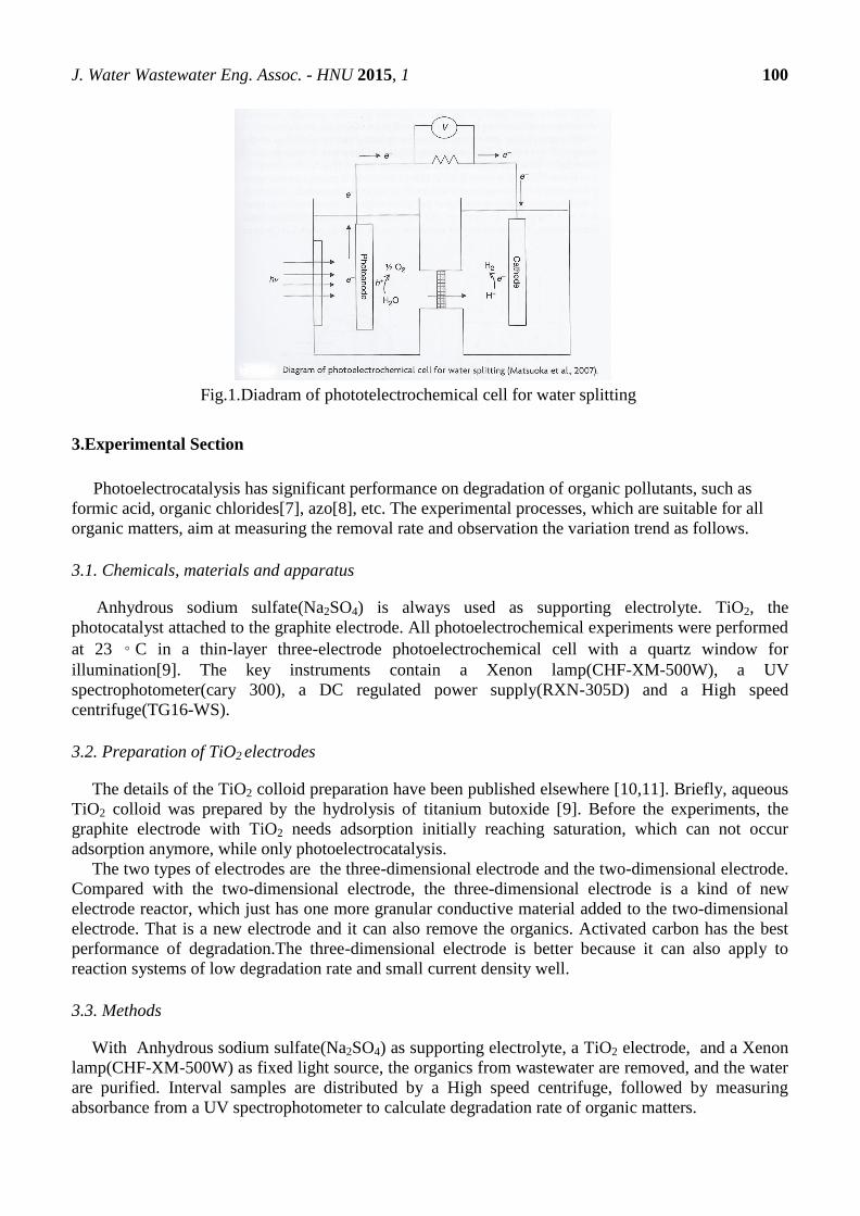
J. Water Wastewater Eng. Assoc. - HNU 2015, 1 100
Fig.1.Diadram of phototelectrochemical cell for water splitting
3.Experimental Section
Photoelectrocatalysis has significant performance on degradation of organic pollutants, such as
formic acid, organic chlorides[7], azo[8], etc. The experimental processes, which are suitable for all
organic matters, aim at measuring the removal rate and observation the variation trend as follows.
3.1. Chemicals, materials and apparatus
Anhydrous sodium sulfate(Na2SO4) is always used as supporting electrolyte. TiO2, the
photocatalyst attached to the graphite electrode. All photoelectrochemical experiments were performed
at 23 ◦ C in a thin-layer three-electrode photoelectrochemical cell with a quartz window for
illumination[9]. The key instruments contain a Xenon lamp(CHF-XM-500W), a UV
spectrophotometer(cary 300), a DC regulated power supply(RXN-305D) and a High speed
centrifuge(TG16-WS).
3.2. Preparation of TiO2 electrodes
The details of the TiO2 colloid preparation have been published elsewhere [10,11]. Briefly, aqueous
TiO2 colloid was prepared by the hydrolysis of titanium butoxide [9]. Before the experiments, the
graphite electrode with TiO2 needs adsorption initially reaching saturation, which can not occur
adsorption anymore, while only photoelectrocatalysis.
The two types of electrodes are the three-dimensional electrode and the two-dimensional electrode.
Compared with the two-dimensional electrode, the three-dimensional electrode is a kind of new
electrode reactor, which just has one more granular conductive material added to the two-dimensional
electrode. That is a new electrode and it can also remove the organics. Activated carbon has the best
performance of degradation.The three-dimensional electrode is better because it can also apply to
reaction systems of low degradation rate and small current density well.
3.3. Methods
With Anhydrous sodium sulfate(Na2SO4) as supporting electrolyte, a TiO2 electrode, and a Xenon
lamp(CHF-XM-500W) as fixed light source, the organics from wastewater are removed, and the water
are purified. Interval samples are distributed by a High speed centrifuge, followed by measuring
absorbance from a UV spectrophotometer to calculate degradation rate of organic matters.

J. Water Wastewater Eng. Assoc. - HNU 2015, 1 101
4. Control Factors
In photoelectrocatalytic experiments, main influence factors of reaction efficiency of
photoelectrocatalytic(PEC) degradation are conductivity, power supply voltage, initial concentration of
organics from wastewater and PH of the solution, etc. To understand the correlation between every
factor and removal of organics from wastewater, the authors compare them respectively as the
following four paragraphs.
4.1. Influence of conductivity
Conductivity has a significant influence on PEC degtadation. If conductivity value is large, strong
current electricity can be examined, and on the contrary, the PEC reaction efficiency is low. The
reason is that the main transfer electronics are nearly from the electrolyte solution but not photo-
electronics.
4.2. Power supply voltage
The influence of power supply voltage on various kinds of organic pollutants is different. In the
certain range, the higher power supply voltage value, the higher removal rate of target chemical.
Because higher power supply voltage value can suppress the combination of photonics and holes. But
when this value gets the top point, then if it increases, the reaction rate will decrease.
4.3. Initial concentration
The initial concentration of the target chemical is related to the reaction order[12]. In a certain range,
with the increase of initial concentration of chemicals, reaction rates also increase. Because the
opposite effects between photocatalysis and electrocatalytic have been suppressed by
photoelectrocatalysis. That is electro-optical synergy[14].
4.4. Influence of PH
The pH of the solution has a close relationship with the reaction rate because the surface charge of
TiO2 and the ionization of chemicals are dependent on this variable[12]. Different PH values result in
changes charge characteristics on the surface of electrodes, and then influence the absorption of TiO2
electrodes. Higher PH makes higher degradation rate of organics. However, when PH value gets too
large, the removal rate will decrease slightly. Different equipotential bonding points correspond
different kinds of target chemicals.
5. Perspective
A lot of people are studying the photoelectrocatalytic oxidation technology of nanometer TiO2,
but also to study the application of this technology in wastewater treatment. This technology can be
used in the wastewater treatment, which can greatly improve the removal rate of the material in the
wastewater. This technology has the characteristics of low energy consumption, no secondary
pollution, low cost, easy operation and maintenance, can be fully realized automatic control and so on.
It is easy to be popularized and applied. After the market analysis, nano photoelectric catalytic
wastewater treatment and other new technologies will usher in a good development period in the
treatment of electroplating wastewater, printing and dyeing wastewater treatment and so on, especially
in the development of the ‘zero discharge’ treatment of electroplating wastewater and printing and
dyeing wastewater [15]. In the course of this technology development in the future, Researchers should
focus on the separation of the TiO2 catalysts, improving the photocatalytic efficiency of nano titanium

J. Water Wastewater Eng. Assoc. - HNU 2015, 1 102
dioxide, expanding the scope of nano titanium dioxide can be used, designing and development of low
energy consumption of high photocatalytic reactor[16.17].
At present, domestic and foreign research is based on two dimensional nano TiO2 photoelectric
catalytic system. However, the system of two dimensional system is limited by the active area of the
module, and in technology, it is difficult to improve the time and space greatly. These reasons make
this approach limited in practical applications. Three dimensional nano TiO2 photoelectric catalytic
system which uses the concept of three-dimensional electrode, can enhance the characteristics of
organic matter, and give full play to the time and space efficiency of photoelectric catalysis. This
technology is researched more in the domestic and will be further research in the future[18]. This
technology is very promising in the wastewater treatment, the treatment effect is good, and it may be
used widely in the future.
As a new technology, photoelectrocatalytic oxidation technology is very effective in wastewater
treatment, but it still has a lot of problems. There are general problems: the conversion efficiency of
light energy is low, most of which are one to three percent, and even lower; the catalyst activity is not
high enough; the catalyst is not good enough, most of which is a series of product distribution; and the
catalyst life is not long enough, its continuous use period is only a few months or a few years. In future
research, it should be emphasized to solve these problems. This will enable the technology to have low
energy consumption, save resources and reduce costs in the practical application process. This
technology will have better development space in sewage treatment.
6. Conclusions
Photoelectrocatalysis is a means of electrochemical assisted photochemical, which is much better
than the pure photocatalysis and light degradation. The application prospect of photoeletrocatlytic
oxidation technology has been developed. Photoelectrocatalytic oxidation technology is more effective
method for the degradation of organic pollutants. It can effectively complete the organic matter
completely mineralized to carbon dioxide and inorganic salt or converted into other useful substances,
so that the organic matter degradation to no toxicity and can be used by people. Because of using the
light energy, the technology saves the resources, it has the potential to become the main technology in
the future environmental management[7].
Author Contributions
Xingan Bo: section1&2;
Yuchao Zhang: section3&4;
Di Zhao: section5&6.

J. Water Wastewater Eng. Assoc. - HNU 2015, 1 103
References
1. Comninellis C. Electrocatalysis in the electrochemical conversion/combustion of organic pollutants for waste
water treatment[J]. Water Purification by Photocatalytic Photoelectrochemical & Electrochemical Processes,
1994, 39(94):1857–1862.
2. Emek B, John G, Farmer P J. High-temperature electrocatalysis using thermophilic P450 CYP119:
dehalogenation of CCl4 to CH4.[J]. Journal of the American Chemical Society, 2004, 126(28):8632-8633.
3. .Egerton T A, Christensen P A, Kosa S A M, et al. Photoelectrocatalysis by titanium dioxide for water
treatment[J]. International Journal of Environment & Pollution, 2006, 27(1-2):2-19.
4. Liu Y, Du H. Study on Photoelectrocatalytic Technology of Three-Dimensional Electrode.[J]. Advances in
Intelligent & Soft Computing, 2011, 104:447-451.
5. Georgieva J, Valova E, Armyanov S, et al. Bi-component semiconductor oxide photoanodes for the
photoelectrocatalytic oxidation of organic solutes and vapours: A short review with emphasis to TiO2–WO3
photoanodes[J]. Cheminform, 2012, 211-212(8):30–46.
6. Karanasios N, Georgieva J, Valova E, et al. Photoelectrocatalytic Oxidation of Organics Under Visible Light
Illumination: A Short Review[J]. Current Organic Chemistry, 2015, 19(6).
7. 陈佩仪, 李彦旭, 孙楹煌,等. 光电催化水处理技术研究进展[J]. 工业水处理, 2005, 12 期(12):13-17.
8. Vinodgopal K ,, Kamat P V. Enhanced Rates of Photocatalytic Degradation of an Azo Dye Using
SnO2/TiO2 Coupled Semiconductor Thin Films[J]. Environ.sci.technol, 1995, 29(3):841-845.
9. Li L, Zhang S, Li G, Zhao H. Determination of chemical oxygen demand of nitrogenous organic
compounds in wastewater using synergetic photoelectrocatalytic oxidation effect at TiO2
nanostructured electrode. Analytica chimica acta. 2012;754:47-53.
10. Zhao H, Jiang D, Zhang S, Catterall K, John R. Development of a direct photoelectrochemical
method for determination of chemical oxygen demand. Anal Chem 2004; 76:155-160.
11. Zhang S, Zhao H, Jiang D, et al. Photoelectrochemical determination of chemical oxygen demand
based on an exhaustive degradation model in a thin-layer cell[J]. Analytica Chimica Acta, 2004,
514(1):89–97.
12. Dong H K, Anderson M A. Solution factors affecting the photocatalytic and photoelectrocatalytic
degradation of formic acid using supported TiO2 thin films[J]. Journal of Photochemistry &
Photobiology A Chemistry, 1996, 94(2):221–229.
13. Walker S A, Christensen P A, Shaw K E, et al. Photoelectrochemical oxidation of aqueous phenol
using titanium dioxide aerogel[J]. Journal of Electroanalytical Chemistry, 1995, 393:137–140.
14. Pelegrini R, Peralta-Zamora P, Andrade A R D, et al. Electrochemically assisted photocatalytic
degradation of reactive dyes[J]. Applied Catalysis B Environmental, 1999, 22(2):83-90.
15. 罗贞礼. 纳米光电催化污水处理技术应用与产业化对策建议[J]. 新材料产业, 2009, 第 9 期:41-45.
16. 李晓平, 徐宝琨, 刘国范,等. 纳米 TiO_2 光催化降解水中有机污染物的研究与发展[J]. 功能材料, 1999, 03 期
(3):242-245.
17. 相会强, 李红兵, 马艳芳,等. 纳米 TiO_2 光催化技术在水污染控制中的应用[J]. 仪器仪表学报, 2007, S1 期.
18. 冯艳文, 梁金生, 梁广川,等. 纳米 TiO2 光电催化降解工业废水技术研究进展[J]. 工业水处理, 2003, 23(10):5-8.

J. Water Wastewater Eng. Assoc. - HNU 2015, 1 104
J. Water Wastewater Eng. Assoc.- HNU, 2015, 1, 104-110.
English for
Water and Wastewater
Engineering Major FALL 2015
http://www.minnwater.com/research/?p=149
Article
Progress in study of electrode materials and application on
Capacitive Deionization
Qiyu Liu1 , Jianqing Liu
2,†, Zijun Wang
2,† and Kuan Z. Huang
3, *
1 Department of Water Engineering and Science, College of Civil Engineering, Hunan University,
Changsha, Hunan 410082, China. E-Mail: [email protected] 2 Department of Water Engineering and Science, College of Civil Engineering, Hunan University,
Changsha, Hunan 410082, China. E-Mail: [email protected]; [email protected]
† These authors contributed equally to this work.
3,* Department of Water Engineering and Science, College of Civil Engineering, Hunan University,
Changsha, Hunan 410082, China. E-Mail: [email protected]; Tel.: +86 150-7313-5174
Academic Editor: H.L. Tang
Received: 5 November 2015 / Accepted: 13 November 2015 / Published: 18 November 2015
Abstract: Capacitive deionization (CDI), as an emerging water treatment technology for
desalination, has rapidly developed over the past decade. With two oppositely posed
electrodes and an applied voltage, the charged particles in water move directionally under
the electric field and are adsorbed onto the electrodes, resulting in water purification. The
growth of this technology not only includes research on theories and impact factors, but
also includes successful cases of engineering applications, indicating its feasibility. It gives
a succinct review of the CDI technology based on research advances from the international
CDI community, including electrode materials, electrode surface characteristics,
application and commercialization, combination with RED, and an outlook on future
research and development.
Keywords: Capacitive deionization (CDI); Desalination; Polar functional groups;
Electrode; Fresh water resources
CE 06015

J. Water Wastewater Eng. Assoc. - HNU 2015, 1 105
1. Introduction
Water is the source of all lives on the earth, and is also one of the most basic element of human’s
survival, including production and living1. However, with the development of industry and agriculture
and population explosion, the limited water resources has become increasingly unable to meet the
needs of human beings, the world more and more began to fall into the predicament of the shortage of
water. To solve this problem, apart from looking for new water resources, reducing waste, controlling
water pollution or changing the using preference of water, salt water desalination is a very bright
choice; it is a way not only ensuring water quality but also guaranteeing abundant fresh water for
people2. Recently, a new type of promising desalination method has attracted more and more attention
in the world, which is called capacitive deionization, or CDI3, 4
.
CDI is a novel water treatment technology. It is an electrochemical-based desalination process in
which the system is composed of a pair of porous electrodes and a DC power supply5. CDI is
potentially attractive for desalination of low salinity sources, such as brackish and surface waters, and
removing trace contaminants from river which is polluted. CDI is a low pressure, low voltage process
and so consumes at least 1/3 less energy than other desalination methods6.
2. Electrode Materials
In CDI technology, the most critical factor equipment efficiency is the electrode materials, huge
amounts of carbon materials, porous carbon materials such as carbon nanotubes and graphene, due to
high specific surface area and chemical stability as well as features such as friendly to environment
and is used as a CDI electrode in-depth study. Among them, the GA for its deliver a unique network
structure excellent physical and chemical properties, crosslinked network structure not only gives the
aerogel great specific surface area, and evenly distributed among them with microporous carbon
particles enhances its electric conductivity, the electric adsorption performance of GA. GA, often
referred to as graphene between molecules or in graphene as the main body and other organic or
inorganic molecules are connected under the condition of certain form of space porous network
structure.
Wang et al.’s7 experiment used PS colloidal templates of the GA prepared and applied to CDI
technology to remove the water salinity. Three-dimensional Internet gives it high conductivity and low
internal resistance, CV test show that the characteristics of the capacitor under 5 mV/s up to 58. 4 F/g,
ensure the efficient transmission, electrons and ions at the same time show a perfect output power
under low energy consumption, the next batch of model CDI test further demonstrated that GA is
efficient CDI electrode materials of excellence.
Yin et al.8 such as the preparation of the GO/TiO2 and applied to CDI aerogel electrodes,
graphene and TiO2 assemble into three-dimensional structure, not only for the inorganic salt ions in
adsorption solution provides a number of big hole site, low toxicity, high stability, high dielectric
constant materials can be improved by the addition of TiO2 further performance of capacitance, all
kinds of test results show that the CDI electrode was prepared by three important parameters: electric
adsorption capacity, rate and reversibility is superior to other materials. Liu et al.9 by KOH activation
was three-dimensional RGO aerogel and applied it in CDI electrode, to obtain the very good ion
J. Water Wastewater Eng. Assoc. - HNU 2015, 1 106
removal effect, different from ordinary electrode materials such as acetylene black form of peer-to-
peer network of conductive RGO aerogel is a kind of ‘dot’ across the conductive network, it is good
for CDI electrode in the electron transfer. Wimalasiri et al.10
such as preparation of graphene layer
water gel CDI electrodes and applied to remove the ammonium ion in the water, at room temperature
under the condition of removal rate can reach 99%, and has a good regeneration performance.
GA, with the macroporous structure not only provides a great adherent surface ion adsorption, and
reduce the resistance in the process of ion transport, but also shortens the ions to the interior electrode
distance, has provided the safeguard for the ion transport, make GA CDI ideal electrode materials.
3. Polar Functional Groups on the Electrodes Surface
In the process of embellishing the surface with some Granular dopants to produce composite
electrodes, the incorporations usually interact with polar functional groups on the surface. Typically,
the stability goes better when affinity between two substance is higher. For example, when decorating
the activated carbon with titanium butoxide under oxidation state, the adhesion force is notably strong
due to countless reduced polar groups on its surface, and then stability would be excellent11, 12
. The
same principle goes with graphene oxide (GO) and reduced graphene oxide (RGO), with which consist
numbers of oxidation of functional groups that can integrate tightly with reduced groups on other
electrode materials to develop stable composite13, 14
. Therefore, GO and RGO have been used greatly
as dopants in CDI field, such as being loaded to carbon aerogel9 and carbon nanofibers
15, 16, and both
shows astonishing characteristics.
The impacts of surface polar groups on adsorption process should cause researchers’ enough
attention. For example, Duan et al.17
pretreated the ordered mesoporous carbon using H2O2 and heat
N2 atmosphere respectively; the former process created more oxygen groups while the latter reduced
them. And the sorption experiment showed that the more the oxygen groups are, the better the
adsorption performance is. Besides, in Zafra et al.’s research18
, the process to activate carbon aerogel
under high temperature CO2 atmosphere created vast hydroxyl and carboxyl and promoted the
hydrophily considerably. As a result, the electrodes demonstrated a much better adsorption
performance. While in Yan et al.’s experiment19
, after modifying the activated carbon with polyaniline,
the increased weak acidic functional groups on surface can amazingly promote the conductivity of the
electrodes, hence improve the desalination performance. Huang et al.20
tried to adsorb Cu2+
using
activated carbon electrodes. For the first experiment, only 69% ions released back to the solution
during desorption process, while the rest was not released due to strong adhesive force. This might
have something to do with the activated groups on the surface of activated carbon. While with the
research going on, they found that 100% desorption can be accomplished on the basement of the first
round adsorption and desorption. This kind of phenomenon may suggest that about 31% Cu2+
was
adsorbed on the electrodes permanently, or some specific groups were coved by Cu2+
and can never be
regenerated. Furthermore, the attempts to perfect electrodes not only improved the specific surface
area or pore diameter and pore structure, but also improved the surface group, like promoting the
hydrophily18, 21-23
.

J. Water Wastewater Eng. Assoc. - HNU 2015, 1 107
However, some researchers point out that the activation of surface groups will change during the
adsorption and desorption process. For example, the activation might be firstly strengthened with the
round process going on, while after a long-term operation, the activation began to decrease24
. In
consideration of this, when desalinating NaCl solution based on carbide derived carbon electrodes,
Porada el at.25, 26
insisted to recording data after operating new reactors for several round process to
achieve a dynamic steady state (DSS) to make sure most parameters of electrodes can remain constant.
So the capacity of adsorption and desorption can have a better balance and he can also get more
accurate results. In addition, some people believe that there are more or less REDOX change on
surface groups during the adsorption and desorption process, and this kind of change can lead to
variation of pH of solution26
. So the result tells us that we should attach importance to maintain the pH
to a limited extent to avoid too drastic change.
4. CDI-RED System
Early studies on CDI date to the mid-1960s and the early 1970s. The concept was first introduced
by Caudle et al., who used porous carbon electrodes made of activated carbon powder in a flow-
through mode for water desalination. Later, Johnson et al. studied CDI as a reversible process27
. Their
work combined parametric studies with investigations of the theoretical basis of CDI and of various
electrode materials28
. CDI works by inducing the adsorption of dis-solved ions on a pair of electrodes
immersed in a solution, upon applying an electric potential or current across these electrodes5. When
this process ends, the adsorbed ions are released into a rinse solution. In doing so, the electrodes
become ready for a new electrosorption cycle27
.
Reverse electro dialysis (RED) is a membrane separation equipment which facilitates the selection
of membrane permeability for separation of the substances in the water29
. It can achieve the purpose of
the desalination. In the RED process, two different salinity water streams are used in producing energy:
a high salinity stream and a low salinity stream. RED has low energy consumption and convenient
operation. There is no need to acid and alkali regeneration membrane separation process and does not
need to add other chemicals. During a dilute chamber into the salty water, turn on the juice and
positively charged cations in the solution. Under the action of an electric field to cathodic direction to
Yang membrane, negatively charged groups on membrane opposites attract role through the
membrane29
. They concentrated on the right side of the chamber. Negatively charged anions move in
the direction of the anode to anion-exchange membrane. By positively charged groups on membrane
opposites attract role through the membrane, the concentration is the left side of the room. Dilute
chamber sodium chloride in the salt water has been removed and get fresh water.
CDI-RED hybrid system is used in the production of salt water desalination and energy
development. A CDI cell can generate a high salinity in the process of discharge flow and generated in
the process of charging and pure water. The brine concentration from the CDI cell can be minimized
by inserting a RED cell next to it. Therefore, using this system, desalinated water and energy could be
generated at the same time30
. In the current study, CDI-RED system has both continuous desalination
of Reverse electro dialysis (RED) and the advantages of Capacitive deionization(CDI)30
. Besides, it
avoids reverse electro dialysis technology farmers polarization and capacitive deionization technology
is negative rearrangement at regular intervals.

J. Water Wastewater Eng. Assoc. - HNU 2015, 1 108
This study demonstrates that CDI-RED system offers an alternative method to produce both
electricity and desalinated water .The dual advantages of the proposed integrated system enhance the
future of desalination technology by creating a desalination method with a lowered brine30
. More
research should be taken in the length of CDI cell, so that we can generate more pure water and more
power. In addition, future research can include minimize salt content and increase the number of
sustainable energy production.
5. Application and Commercialization of CDI
Carbon aerogel is a lightweight, porous, nanoscale amorphous carbon material, which has large
specific surface, good conductivity, excellent mechanical properties, so it is suitable as an electrode
material. Farmer and Pekala etc.31
in the US Lawrence Livermore National Laboratory develop a
removal device using stack carbon aerogel electrode to aqueous electrolyte ions. The result shows that
the apparatus that remove sodium, chlorine, chromium, ammonium, cadmium, zinc, lead, copper,
manganese, calcium, uranium etc. has a good effect.
The first attempts toward to commercialization of CDI began in 2000, when two US companies,
Biosource, Inc. and Sabrex of Texas, Inc., were awarded a contract from the Defense Advanced
Research Products Agency (DARPA) to develop a prototype portable water treatment unit based on
CDI for the US Army. At the same time, the US Far West Group, Inc. received a development contract
from Arizona Public Service (APS) to supply a CDI prototype for a water purification system for study
by APS3.
Based on the above activity, Sabrex launched the electronic water purifier (EWP), declaring it to be
capable of removing dissolved ions, including iron, arsenic, chrome, perchlorate and nitrate, and of
treating brackish, sea waters and waste waters. According to the developer, the unit is also suitable for
use as home water purifier in conjunction with UV3.
Recently, CDT Systems, Inc., a Texas based company, announced the launch of a mobile CDI
system. Their technology is also presented as a technology suitable for water treatment in disaster
areas. However, the commercialization status of the mobile unit was not made clear in the presentation.
It should be mentioned that all the technologies mentioned above make use of a carbon aerogel as the
electrode material3.
In summary, the capacitive deionization is a potential electrolyte - water separation methods.
Abroad, especially the United States, is very active for the research and developing applications,
industry progress is also quickly, but these researches in our country are very little and scattered,
relatively speaking there is a large gap with abroad. In view that the capacitive deionization has some
characteristics such as efficient and pollution-free, which is conform to the country's environmental
policy, we proposed that related department pay attention to this regard, which can promote the
development in terms of capacitive deionization.
6. Conclusions
In the past decade, capacitive deionization technology has gotten unprecedented development in
many aspects, including selection and modification of electrode materials, explosion of influential
factors, the development of large scale device, and application and commercialization. We can notice

J. Water Wastewater Eng. Assoc. - HNU 2015, 1 109
that more and more researchers are putting passion to the study of this field. So we believe that CDI
will gradually replace the existing traditional desalination methods in the near future, providing human
with water for living and production low-costly and uninterruptedly, and eventually solve the problem
of global water crisis.
Author Contributions
Qiyu Liu contributed to section 1&5.
Jianqing Liu contributed to section 2.
Zijun Wang contributed to section 1&4.
Kuan Z. Huang contributed to section 1&3&6 and Abstract & Keywords & Conclusions.
References and Notes
1. A. T, Claudio C, C. M, L. RM. Global warming and water sustainability. E3S Web of
Conferences 2014, 2006.
2. Service RF. Desalination freshens up. Science 2006, 313, 1088-90
3. Oren Y. Capacitive deionization (CDI) for desalination and water treatment — past, present
and future (a review). Desalination 2008, 228, 10-29.
4. Farmer JC, Fix DV, Mack GV, Pekala RW, Poco JF. Capacitive deionization of NH4CIO4
solutions with carbon aerogel electrodes. Journal of Applied Dlectrochemistry 1996, 1007-18.
5. Minhas MB, Jande YAC, Kim WS. Combined reverse osmosis and constant-current operated
capacitive deionization system for seawater desalination. Desalination 2014, 344, 299-305.
6. Anderson MA, Cudero AL, Palma J. Capacitive deionization as an electrochemical means of
saving energy and delivering clean water. Comparison to present desalination practices: Will it
compete? Electrochimica Acta 2010, 55, 3845-56.
7. Wang H, Shi L, Yan T, Zhang J, Zhong Q, Zhang D. Design of graphene-coated hollow
mesoporous carbon spheres as high performance electrodes for capacitive deionization. Journal of
Materials Chemistry A 2014, 2, 4739-50.
8. Yin H, Zhao S, Wan J, Tang H, Chang L, He L, et al. Three-dimensional graphene/metal oxide
nanoparticle hybrids for high-performance capacitive deionization of saline water. Adv Mater 2013,
25, 6270-6.
9. Liu Y, Nie C, Pan L, Xu X, Sun Z, Chua DHC. Carbon aerogels electrode with reduced
graphene oxide additive for capacitive deionization with enhanced performance. Inorganic Chemistry
Frontiers 2014, 1, 249-55.
10. Wimalasiri Y, Mossad M, Zou L. Thermodynamics and kinetics of adsorption of ammonium
ions by graphene laminate electrodes in capacitive deionization. Desalination 2015, 357, 178-88.
11. Ryoo M-W, Kim J-H, Seo G. Role of titania incorporated on activated carbon cloth for
capacitive deionization of NaCl solution. Journal of colloid and interface science 2003, 264, 414-9.
12. Ryoo M-W, Seo G. Improvement in capacitive deionization function of activated carbon cloth
by titania modification. Water research 2003, 37, 1527-34.
13. Huang H-D, Ren P-G, Chen J, Zhang W-Q, Ji X, Li Z-M. High barrier graphene oxide
nanosheet/poly(vinyl alcohol) nanocomposite films. Journal of Membrane Science 2012, 409-410,
156-63.
14. Yang X, Tu Y, Li L, Shang S, Tao XM. Well-dispersed chitosan/graphene oxide
nanocomposites. ACS applied materials & interfaces 2010, 2, 1707-13.
15. Bai Y, Huang Z-H, Yu X-L, Kang F. Graphene oxide-embedded porous carbon nanofiber webs
by electrospinning for capacitive deionization. Colloids and Surfaces A: Physicochemical and
Engineering Aspects 2014, 444, 153-8.

J. Water Wastewater Eng. Assoc. - HNU 2015, 1 110
16. Dong Q, Wang G, Qian B, Hu C, Wang Y, Qiu J. Electrospun Composites Made of Reduced
Graphene Oxide and Activated Carbon Nanofibers for Capacitive Deionization. Electrochimica Acta
2014, 137, 388-94.
17. Duan F, Li Y, Cao H, Xie Y, Zhang Y. Capacitive deionization by ordered mesoporous carbon:
electrosorption isotherm, kinetics, and the effect of modification. Desalination and Water Treatment
2013, 52, 1388-95.
18. Zafra MC, Lavela P, Rasines G, Macías C, Tirado JL, Ania CO. A novel method for metal
oxide deposition on carbon aerogels with potential application in capacitive deionization of saline
water. Electrochimica Acta 2014, 135, 208-16.
19. Yan C, Zou L, Short R. Polyaniline-modified activated carbon electrodes for capacitive
deionisation. Desalination 2014, 333, 101-6.
20. Huang SY, Fan CS, Hou CH. Electro-enhanced removal of copper ions from aqueous solutions
by capacitive deionization. Journal of hazardous materials 2014, 278, 8-15.
21. Hojati-Talemi P, Zou L, Fabretto M, Short RD. Using oxygen plasma treatment to improve the
performance of electrodes for capacitive water deionization. Electrochimica Acta 2013, 106, 494-9.
22. Saikia N, Deka RC. Density functional calculations on adsorption of 2-
methylheptylisonicotinate antitubercular drug onto functionalized carbon nanotube. Computational
and Theoretical Chemistry 2011, 964, 257-61.
23. Hou C-H, Liu N-L, Hsu H-L, Den W. Development of multi-walled carbon
nanotube/poly(vinyl alcohol) composite as electrode for capacitive deionization. Separation and
Purification Technology 2014, 130, 7-14.
24. Yang J, Zou L. Recycle of calcium waste into mesoporous carbons as sustainable electrode
materials for capacitive deionization. Microporous and Mesoporous Materials 2014, 183, 91-8.
25. Porada S, Borchardt L, Oschatz M, Bryjak M, Atchison JS, Keesman KJ, et al. Direct
prediction of the desalination performance of porous carbon electrodes for capacitive deionization.
Energy & Environmental Science 2013, 6, 3700.
26. Porada S, Weinstein L, Dash R, van der Wal A, Bryjak M, Gogotsi Y, et al. Water desalination
using capacitive deionization with microporous carbon electrodes. ACS applied materials & interfaces
2012, 4, 1194-9.
27. Lado JJ, Pérez-Roa RE, Wouters JJ, Isabel Tejedor-Tejedor M, Anderson MA. Evaluation of
operational parameters for a capacitive deionization reactor employing asymmetric electrodes.
Separation and Purification Technology 2014, 133, 236-45.
28. Jande YA, Kim WS. Integrating reverse electrodialysis with constant current operating
capacitive deionization. Journal of environmental management 2014, 146, 463-9.
29. Feng C, Hou CH, Chen S, Yu CP. A microbial fuel cell driven capacitive deionization
technology for removal of low level dissolved ions. Chemosphere 2013, 91, 623-8.
30. Porada S, Bryjak M, van der Wal A, Biesheuvel PM. Effect of electrode thickness variation on
operation of capacitive deionization. Electrochimica Acta 2012, 75, 148-56.
31. Richardson JH, LLNL. Capacitive deionization system1996. Medium: ED; Size: 11 pages;
Other: FDE: PDF p.
J. Water Wastewater Eng. Assoc. - HNU 2015, 1 111
J. Water Wastewater Eng. Assoc.- HNU, 2015, 1, 111-119.
English for
Water and Wastewater
Engineering Major FALL 2015
http://www.minnwater.com/research/?p=149
Article
Special treatment of industry sewage
Jing Wang 1,
*, Ziju Wang 2,†
and Jiajian Luo 3
4 School of Civil Engineering, Hunan University,the third class of Water Supply and Drainage
Science and Engineering
Hunan University, Dezhi Yuan
Jing Wang E-Mails:[email protected] Tel:15962572718
5 School of Civil Engineering, Hunan University,the third class of Water Supply and Drainage
Science and Engineering
Hunan University, Dezhi Yuan
Ziju Wang E-Mails:[email protected] Tel:15575932041
6 School of Civil Engineering, Hunan University,the second class of Water Supply and Drainage
Science and Engineering
Hunan University, Dezhi Yuan
Jiajian Luo E-Mails:[email protected] Tel:15367888801
Academic Editor: H.L. Tang
Received: 5 November 2015 / Accepted: 13 November 2015 / Published: 18 November 2015
Abstract: Industry wastewater pollution has been a very serious problem in the last few
years. Finding the better treatment and combined method process is very necessary.To
treat different kinds of wastewater,different professors show us different solutions. In a
word ,what the professors look for is a simple, effective and economical treatment.
Keywords: different wastewater treatment pharmaceutical wastewater High-salt
wastewater Petrochemical wastewater
Introduction
Nowadays ,industry develops rapidly,but the industry wastewater is hard to deal with.The
industry wasetwater treatment has been a serious social problem .So we had better find
some effective and economical treatment methods or the better combined
method process.There are some typical industry wastewater treatment .
CE 06015
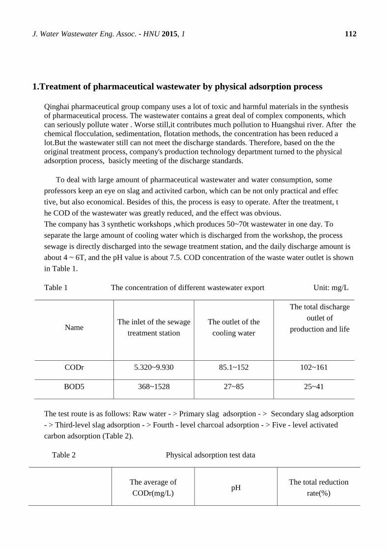
J. Water Wastewater Eng. Assoc. - HNU 2015, 1 112
1.Treatment of pharmaceutical wastewater by physical adsorption process
Qinghai pharmaceutical group company uses a lot of toxic and harmful materials in the synthesis
of pharmaceutical process. The wastewater contains a great deal of complex components, which
can seriously pollute water . Worse still,it contributes much pollution to Huangshui river. After the
chemical flocculation, sedimentation, flotation methods, the concentration has been reduced a
lot.But the wastewater still can not meet the discharge standards. Therefore, based on the the
original treatment process, company's production technology department turned to the physical
adsorption process, basicly meeting of the discharge standards.
To deal with large amount of pharmaceutical wastewater and water consumption, some
professors keep an eye on slag and activited carbon, which can be not only practical and effec
tive, but also economical. Besides of this, the process is easy to operate. After the treatment, t
he COD of the wastewater was greatly reduced, and the effect was obvious.
The company has 3 synthetic workshops ,which produces 50~70t wastewater in one day. To
separate the large amount of cooling water which is discharged from the workshop, the process
sewage is directly discharged into the sewage treatment station, and the daily discharge amount is
about 4 ~ 6T, and the pH value is about 7.5. COD concentration of the waste water outlet is shown
in Table 1.
Table 1 The concentration of different wastewater export Unit: mg/L
Name The inlet of the sewage
treatment station
The outlet of the
cooling water
The total discharge
outlet of
production and life
CODr 5.320~9.930 85.1~152 102~161
BOD5 368~1528 27~85 25~41
The test route is as follows: Raw water - > Primary slag adsorption - > Secondary slag adsorption
- > Third-level slag adsorption - > Fourth - level charcoal adsorption - > Five - level activated
carbon adsorption (Table 2).
Table 2 Physical adsorption test data
The average of
CODr(mg/L) pH
The total reduction
rate(%)
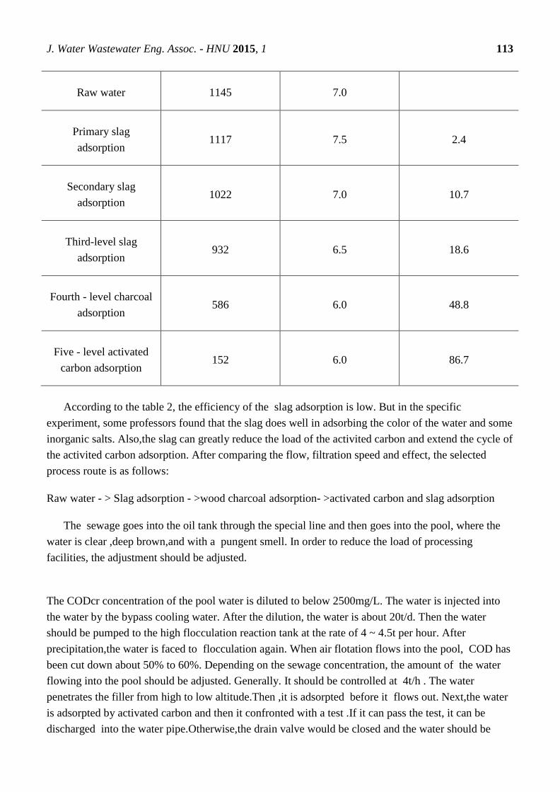
J. Water Wastewater Eng. Assoc. - HNU 2015, 1 113
Raw water 1145 7.0
Primary slag
adsorption 1117 7.5 2.4
Secondary slag
adsorption 1022 7.0 10.7
Third-level slag
adsorption 932 6.5 18.6
Fourth - level charcoal
adsorption 586 6.0 48.8
Five - level activated
carbon adsorption 152 6.0 86.7
According to the table 2, the efficiency of the slag adsorption is low. But in the specific
experiment, some professors found that the slag does well in adsorbing the color of the water and some
inorganic salts. Also,the slag can greatly reduce the load of the activited carbon and extend the cycle of
the activited carbon adsorption. After comparing the flow, filtration speed and effect, the selected
process route is as follows:
Raw water - > Slag adsorption - >wood charcoal adsorption- >activated carbon and slag adsorption
The sewage goes into the oil tank through the special line and then goes into the pool, where the
water is clear ,deep brown,and with a pungent smell. In order to reduce the load of processing
facilities, the adjustment should be adjusted.
The CODcr concentration of the pool water is diluted to below 2500mg/L. The water is injected into
the water by the bypass cooling water. After the dilution, the water is about 20t/d. Then the water
should be pumped to the high flocculation reaction tank at the rate of 4 ~ 4.5t per hour. After
precipitation,the water is faced to flocculation again. When air flotation flows into the pool, COD has
been cut down about 50% to 60%. Depending on the sewage concentration, the amount of the water
flowing into the pool should be adjusted. Generally. It should be controlled at 4t/h . The water
penetrates the filler from high to low altitude.Then ,it is adsorpted before it flows out. Next,the water
is adsorpted by activated carbon and then it confronted with a test .If it can pass the test, it can be
discharged into the water pipe.Otherwise,the drain valve would be closed and the water should be

J. Water Wastewater Eng. Assoc. - HNU 2015, 1 114
adsorpted again. The cycle of the filling operation is 40 to 50 days. If the water still exceeds the
standards after the second adsorption , the packing will be replaced. After saturation,the filler is
transported to the coal yard and mixed before being burned.
Table 3 Trial run for 42 days
The average of COD(mg/L) Reduction rate(%)
Wastewater conditioning pool 2143
Flocculation gas surfaced 1084
Slag adsorption effluent 951 13
Charcoal adsorption effluent 689 37
Activated carbon adsorption
effluent 279 75
Table 4 the COD data of 5 days
The
fifth
day
The
tenth
day
The
fifteenth
day
The
twentieth
day
The
twenty-
fifth
day
The
thirtieth
day
The
thirty-
fifth
day
The
fortieth
day
The
forty-
second
day
CODcr(mg/L) 204 223 256 284 269 276 291 304 413
The company’s production is designed by the national plan, raw materials, equipment and other
factors. As the production status is not stable, the pH, COD concentration and some others of the
wastewater change a lot. The physical adsorption is more suitable for the company's water quality
characteristics and production characteristics, as it just needs small investment, simple operation and
easy management. The treatment of wastewater is up to5400t per year,including about 22.5t reduction
of COD.
In some ways,this method should be further improved.Firstly, the PH is hard to control, which affects

J. Water Wastewater Eng. Assoc. - HNU 2015, 1 115
adsorption. Secondarily, such large amount of wastewater cannot be fully contacted in such short time.
Thirdly ,the water is not very uniform when it goes into the adsorption pool. Forthly ,it’s necessary to
further improve the adsorption efficiency, reduce the amount of fillers, and extend the time of
adsorption.
2.High-salt wastewater treatment
High salt wastewater is a kind of wastewater containing the total salt content of at least 1%. It mainly
comes from chemical plant and oil and natural gas collection and processing. The wastewater contains
many substances (including salt, oil, organic heavy metals and radioactive substances).[4]
High salt wastewater is one of the difficult and hot spots in domestic and foreign research. The
biological method and physical chemistry method are applied in the treatment of high salinity
wastewater. Biological method shows higher organic removal rate when treating high salt wastewater.
But when the biological method is used to treat high salt wastewater, it usually needs for long time. In
addition, microbe is sensitive to environment,so salinity mutations usually cause serious interference to
the processing system. Physical and chemical methods mainly include evaporation method,
electrochemical method, ion exchange method, adsorption, membrane separation technology and so
on,which can remove salt and organic matter in wastewater in some applications, but they are
generally facing higher costs, and easily lead to the second pollution of renewable waste water.So the
effective combination of physical ,chemical methods and biological methods is one of the important
directions of high salt wastewater treatment in the future.[3]
Conventional biochemical method is currently the most widely used wastewater treatment technology,
but salt in high salt wastewater greatly limits the processing performance of microorganisms.So
reducing salt in high salt wastewater is a safeguard measure using conventional biochemical method.
The process of electric dialysis-activated sludge uses electrodialysis device, and the use of low salt
content of the absorption liquid makes the salt in the high salt wastewater transfer to the low salt water
because of the potential difference and the concentration difference of the liquid.It can study the
migration of salt and organic matter in the process of desalination and use biological method to further
reduce wastewater’s COD after the electrodialysis desalination.
2.1 Introduction
In this study, the high salt wastewater treatment process is consists of two parts; electrodialysis
desalination and activated sludge biochemical treatment, and the process is shown in Figure 1.[3]
Electrodialyze
r
Absorbing liquid
Activated sludge reactor
Water
Low-salt wastewater
Absorbing liquid
High-salt wastewater

J. Water Wastewater Eng. Assoc. - HNU 2015, 1 116
First, through the high salinity wastewater into desalination channel of electrodialysis and the low salt
draw fluid into the draw channel, and make wastewater and draw fluid in the electrodialyzer begin
reverse circulation and keep salt in wastewater always higher than the draw fluid of salt. After adding
the DC electric field, ion of wastewater transfers to the draw fluid because of the potential difference
and the concentration difference of the liquid, so salinity in wastewater is reduced to the conditions
suitable for the treatment of activated sludge process.Then use biological treatment of wastewater after
electrodialysis desalination to reduce COD in wastewater by activated sludge reactor after successful
inoculation, domestication and cultivation.[4]
2.2 Results and analysis
2.2.1 Analysis of electrodialysis desalination process
The electrical conductivity of the wastewater and the absorption liquid is measured in the test
process. The results are shown in Figure 2.
The electrolyte in the wastewater is driven by the concentration difference and the potential difference
to the absorption liquid, which reduces the salt content and the electrical conductivity of the
wastewater.
2.2.2 Removal of inorganic ions
To monitor the change in concentrations of ions in wastewater of electrodialysis desalination
process, and the ion removal rate was plotted against time, as shown in Figure 3.
Figure 1
Figure 2

J. Water Wastewater Eng. Assoc. - HNU 2015, 1 117
With the desalination process, various ions in wastewater was driven by continuous to draw fluid
because of the concentration difference and potential difference, making the ion removal rate increases
with time increasing.[3]
2.2.3 Change of COD in desalination process
Absorbing liquid was replaced by 5 times during electrodialysis desalination process. Measure the
COD of the wastewater after every change and the desalting process was completed,and the COD of
the wastewater was respectively 3 850,3 740,3 680,3 640, 3 610,3 590 mg / L. The results showed that
COD of wastewater with desalination process were decreased but reduced to a lesser extent.The initial
COD of the wastewater was 3 850 mg / L,and at the end of the desalination process it was 3590
mg/L .By the change of COD, it was known that after the first replacement COD’s change in
wastewater was the biggest. Then the change was getting smaller and smaller.
2.2.4 Electrodialysis desalination wastewater treatment by activated sludge method
Biochemical degradation of electrodialysis desalination wastewater by successfully acclimated
activated sludge reactor reacts for 24 h. The effluent COD and removal rate was shown in Figure 4.
Figure 3
Figure 4
J. Water Wastewater Eng. Assoc. - HNU 2015, 1 118
The experimental results showed that after 14 days of acclimation period, activated sludge reaction
system had a good result of acclimation and electrodialysis desalination wastewater COD had stable
removal capacity.[3]
2.3Conclusion
Using electricdialysis-activated sludge process with the absorbing liquid to treat wastewater of
high salt can greatly reduce wastewater COD after reducing the amount of salt in the wastewater.So I
think the electrodialysis-activity sludge method provides a good new method for the treatment of high
salt wastewater.
3.Petrochemical industry wastewater treatment
China is a developing country ,water pollution problem has been very serious. The petrochemical
industry discharge a large namber of wastewater . At present, most Chinese oilfield has been the later
stage of oil production , the moisture content of crude oil has amounted to 70 ~ 80%, some oilfields’
even has reached to 90%.As a result,when we separate oil from the crude oil,more waste water will be
discharged . Nowdays,the treatment of the petrochemical wastewater has been a large puzzle for the oil
production.It is one of the hottest issues for the environmental protection scientific research workers’
research .There are some petrochemical waste water treatment methods[5]
.
3.1Chemical oxidation treatment
At present,the chemical oxidation treatments which are used in petrochemical waste water
treatment are ozone oxidation method ,UV/O3 oxidation method ,UV/H2O2 oxidationmethod
,catalytic oxidationmethod and so on. Oxidation is generally as a preprocessing technique or in
combination with other methods. The COD of Suizhong certain oilfield waste water from 628.1 mg/L
fell to 280 ~ 320 mg/L after oxidized by ozone oxidation, and the average removal rate was 31.9%.[6]
3.2Gravitational separation process
Gravity separation is a typical primary treatment process.Oil density is difference from water ,and
oil is insoluble in water. So we can separate the water, oil bead and suspended solids from the
wastewater .This method can remove the dispersed oil,heavy oil and the hazardous substance which is
insoluble in water . But we can't remove the emulsified oil and soluble oil in the wastewater .[5]
3.3Adsorption method
Adsorption method is use the large specific surface area material to adsorbed pollutants of
wastewater,it has better effect than the other methods on removing the macromolecular organic
pollutants.People use this method widely in the petrochemical wastewater treatment for the last few
years.For example,ET Ventues puted the amine polymers into the bentonite,to make the modified
organic clay adsorbent.And he used the modified organic clay adsorbent to absorb the petrochemical
wastewater of Teapot Dome oilfield.Then the waste water absorbed by GAC( Granular activated
carbon).He found that the material content of the total petroleum hydrocarbons,oil and benzene in
waste water were all less then 0.5μg/L.Since the adsorbent adsorption capacity is limited,and the
J. Water Wastewater Eng. Assoc. - HNU 2015, 1 119
processing cost id higher than the other metheds,adsorption method generally used in the deep
treatment of the petrochemical waste water.[6]
In order to solve the petrochemical wastewater treatment problem,finding a better treatment or
combined method process is very impotant.While,on the other hand ,we also should try our best to
reduce the emissions of sewage in the process of production.
Author Contributions
Jing Wang is responsible for the first part--Treatment of pharmaceutical wastewater by physical
adsorption process.The second part--High-salt wastewater treatment belongs to Ziju Wang. Jiajian
Luo made contribution to the third part--Petrochemical industry wastewater treatment.
Best regards
References and Notes
[1].Mansheng.Zhang; Jinsong.Zhang, Treatment of pharmaceutical wastewater by physical
adsorption process. Qinghai environment , 1999,03,106-107
[2].http://wenku.baidu.com/link?url=RgNzhH60ohf9O7Oynxi-xn0qPk6C7hIgRag_eXLl8-
sRenAHyeYPQdfsfqVn_EmgoG_U3UHtYy2yBxLt-OVAt9Zoc2VnuKF_UTTU1Px3ZV7
(accessed on 3th /November/ 2015).
[3].High-salt wastewater treatment method http://www.dowater.com/jishu/2015-01-28/315040.html
2005,01,18
[4]. http://baike.baidu.com/link?url=-PAIhhbcSdc-cU1LZmrTzpbjZ-
dHHobotNJVU0oNrLSoDO8HPLG1d2GGQ3fI4__KpfdAcC0r_c6ByfCU6lJ3aa
[5]. Chengfen.Wang; Petrochemical high concentration organic wastewater treatment technology.
SCIENCE & TECHNOLOGY INFORMATION 2007(36).
[6]. LI Yan-hong , XIE Qing-lin; Technology of oil extraction wastewater treatment and application.
JOURNAL OF GUILIN INSTITUTE OF TECHNOLOGY Vol .23 No .1 Jan.2003.
J. Water Wastewater Eng. Assoc. - HNU 2015, 1 120
J. Water Wastewater Eng. Assoc.- HNU, 2015, 1, 120-126.
English for
Water and Wastewater
Engineering Major FALL 2015
http://www.minnwater.com/research/?p=149
Article
Water pollution investigation for public health
Jiajun Mi 1,
*, Daning Jiang 2,†
, and Lizhong Lan 3†
1 College of civil engineering of Hunan University, Hunan University, Changsha 410000, China;
E-Mail: [email protected]; 2 College of civil engineering of Hunan University, Hunan University, Changsha 410000, China;
E-Mail:[email protected]; 3 College of civil engineering of Hunan University, Hunan University, Changsha 410000, China;
E-Mail: [email protected];
* College of civil engineering of Hunan University, Hunan University, Changsha 410000, China;
E-Mail: [email protected];
Academic Editor: H.L. Tang
Received: 5 November 2015 / Accepted: 13 November 2015 / Published: 18 November 2015
Abstract: We investigated the drinking water pollutions in China from 1996 to 2006.We
expected to provide recommendations for the policy of health and drinking water safety, and make
people to pay attention to public health. The distribution of drinking water contamination cases,
causes, effects of health were analyzed. From 1996 to 2006, there are 271 cases of sudden drinking
water pollution in this project, except for Tibet Province, sudden drinking water pollutions happened in
all provinces and autonomous regions of China.177 cases of 271 cases are pathogenesis. The number
of Biological pollution, chemical pollution, mixed pollution cases were 171, 92, 8, accounting for
63.1%, 3%, 33.9% respectively. Drinking water pollutions affected more than 700 million, of which
30798 people showed symptoms of poisoning or infection, nine people have died due to pollutions.
The main causes of pollution are industrial pollution, sewage, garbage and excrement. The main reason
is the lack of effective protection and management, water purification and disinfection; illegal grafting
to sewage pipes caused intrusion of waste water. We should strengthen the residents’ security
awareness and health management of drinking water.
Keywords: public health; water pollution; water quality;
CE 06015
J. Water Wastewater Eng. Assoc. - HNU 2015, 1 121
1. Introduction
Potable water is an essential factor in human survival as well as the important medium of the
spreading of the disease. With the rapid development of the economy, the increase of the population
and the acceleration of the urbanization process, many rivers, lakes and groundwater in China had been
polluted more or less. It made a series of major water pollution on public health emergencies. To grasp
potable water pollution of emergent public health events comprehensively, improve the work ability of
the potable water health supervision and administration, ensure the safety of potable water effectively
and protect the public health, the ministry of health organized a task to collect case of potable water
pollution emergency in 2006.Based on the various cases reported from the provinces throughout the
land(the reports from the media online are not included),the author analyzed the characteristic, the
reason and the damage of the case of potable water pollution emergency and then offered some
suggestions about the potable water safety management in our country.
1. Materials & Methods
1.1 Data sources
The emergencies of potable water pollution happened in the neighborhood between 1996 and 2006
which are grasped by health department at all levels. Paper reports published on learned periodical
through CNKI database and the retrieval of WANFANG database
; Through GOOGLE and Baidu search engine retrieval in the network media to release water pollution
of emergent public health event information; Using Epi - info software was used to compare the input
data and calibration, no repeat screening case as a case of statistics.
1.2 Case definition
Chemical contamination index of potable water exceeds national drinking water health standards,
cause its not drinking and cause chemical poisoning incidents. Biological contamination index of
potable water bacteriology indicators exceed national drinking water health standards, cause infectious
disease by water.
Mixed pollution incident refers to the above two kinds of pollution
1.3 Statistical analysis
Use chi-square to analyze the distribution characteristics of the case of tainted potable water pollution
emergency. Statistical analysis uses SAS 9.1 software package. Inspection level: α= 0.05
2. Results and Discussion
2.1 Statistics of Investigation
We collected 302 cases of drinking water contamination incidents which happened in China from
1996 to 2006,including 126 cases provincial health administrative departments reported,accounting
for 41.7% of all the cases,145 cases from CNKI database and the database searching in academic
journals, accounting for 48.0%,31 cases from news reports, accounting for 10.3% of the total, which is
not a part of this investigation .Therefore the total number of water contamination incidents in this
investigation is 271. The number of Biological pollution, chemical pollution, mixed pollution cases
were 171, 92, 8, accounting for 63.1%, 3%, 33.9% respectively.

J. Water Wastewater Eng. Assoc. - HNU 2015, 1 122
2.2 The time distribution characteristic of sudden drinking water pollution
2.2.1 Dynamic change
The number of cases happened in every year is different. Most of the pollution cases happened
between 2004 and 2006.The average annual number of drinking water pollution case is about 17 from
1996 to 2003. From 2004 to 2006, the average number is 45.
Figure 1. Dynamic change of water pollution
2.2.2 Seasonality
The survey of 271 cases of national drinking water pollution from 1996 to 2006 indicated that
time distribution of pollutions has certain seasonal characteristics (Table 1). The biological pollution is
obviously seasonal. The number of biological pollutions in winter was significantly lower than that in
other seasons. Chemical pollution cases are also obviously seasonal. It tends to outbreak in summer.
But there were no significant seasonal differences. The number of mixed pollution cases is too small.
Table 1. Seasonality of water pollutions
category number
of cases
spring summer autumn winter
number of
cases percentage(%)
number of
cases percentage(%)
number of
cases percentage(%)
number of
cases percentage(%)
biological pollution
171 47 68.1 52 62.7 47 68.1 25 50
chemical pollution
92 18 26.1 30 32.1 21 30.4 23 46
mixed pollution
8 4 5.8 1 1.2 1 1.5 2 4
total 271 69 100 84 100 69 100 50 100
J. Water Wastewater Eng. Assoc. - HNU 2015, 1 123
2.3 The regional distribution of sudden drinking water pollution
2.3.1 The regional distribution
From 1996 to 2006, there are 271 cases of sudden drinking water pollution in this project, except
for Tibet Province, sudden drinking water pollutions happened in all provinces and autonomous
regions of China.
2.3.2 The distribution of urban and rural areas
There are apparent differences between urban and rural areas. The total number of urban cases is
less than that of rural areas. The pathogenesis of urban water pollution is also significantly lower than
that of the rural areas. 58 urban water pollutions are hazardous to health, accounting for 53.7% of the
total number of urban water pollution. 119 rural water pollutions hazarded health, accounting for 73%
of the total number of rural water pollution cases. The difference of the proportion of pathogenesis
between urban and rural areas was statistically significant.
Constitute of 271 cases nationwide burst water pollution is different between urban and rural
areas. Urban water pollution cases based mainly in the case of biological contamination, accounting
for 89.7 percent of the total urban pollutions; rural water pollution cases are mainly biological
contamination cases and chemical pollution. Biological pollution cases accounted for 74.8 percent of
the total rural cases, while chemical pollution cases accounted for 25.2% of the total cases in rural
areas. After Mantel Haenszel stratified χ2 test, we could inferred that the difference of water pollution
in urban and rural areas was statistically significant (χ2 = 36.288, P <0.001).
2.4 Effects of sudden water pollution cases
In these 271 cases from 1996 to 2006, the cumulative affected population reached more than 7.0
million. 30,798 people suffered a disease because of these pollutions; nine people were killed
(including seven people died of arsenic poisoning, one person died of paratyphoid, one person died of
benzene poisoning). The health effects of drinking water contamination including intestinal infectious
diseases, infectious diarrhea and chemical poisoning.Infectious diarrhea means diarrhea that caused by
E. coli and other non-pathogenic pathogens. Intestinal infectious is diarrhea caused by the pathogenic
intestinal pathogens. Health effects of urban and rural drinking water contaminated by the χ 2 test
configuration are statistically significant.
2.4.1 Intestinal infections
The project statistics 271 cases of sudden drinking water pollution which resulted in 27,063
people infecting intestinal symptoms. 11,572 people suffer from intestinal infectious diseases among
them. There is a big difference in the intestinal diseases caused by drinking water contaminated
between the urban and rural areas. The number of people suffering from rural areas is much higher
than that in urban areas, number of rural incidence of cholera is eight times the city, number of rural
typhoid, paratyphoid incidence of 2.4 times the city. The number of cases of diarrhea in rural areas is
2.4 times the city.
2.4.2 Chemical poisoning

J. Water Wastewater Eng. Assoc. - HNU 2015, 1 124
271 cases of sudden drinking water pollution had led to a total of 3195 chemical poisoning. The
number of chemical poisoning in cities is only 221; accounting for 1.7% of the total urban incidence,
except the 13 nitrite poisoning and other 208 people had no specific poisoning symptoms. The number
of chemical poisoning in rural areas of 2974, it is 13.5 times the number of city (accounting for 17.8%
of total number of incidences), including pesticide poisoning (419 people), arsenic poisoning (1,023
people), cyanide poisoning (150 people), nitrite poisoning (46 persons) and other chemical poisoning
(1336 people).
2.5 The causes of sudden water pollution
According to the nature of pollutants, there are biological contamination (171 cases, 63.1%),
chemical pollution (92 cases, 33.9%) and mixed pollution (8 cases, 3.0%).
The main cause of 171 biological pollutions is domestic waste (sewage, garbage and feces)
pollution and contamination of inverted siphon because of pipe breakage (accounted for 80.1% of
cases biological contamination together). The main aspects of biological pollution are the water pipe
network pollution and water supply for itself contamination (biological pollution cases accounted for
64.9% together); 92 chemical pollution cases happened mainly due to illegal operation of industrial
and agricultural production, traffic accidents and water using units( accounted for 80.4% of chemical
contamination cases together). The main aspects of chemical pollution incident are water resource
pollution and water pipe network pollution (accounting for 73.9% of chemical pollution cases
together).
2.6 The causes of pollution, environmental pollution and health hazards
177 nationwide sudden drinking water pollutions (65.3%) are pathogenesis in all the 271 cases
from 1996 to 2006. Making up all the 177 pathogenesis cases, 16 drinking water pollution cases,
caused by industrial pollution, led to 2372 people had health problems. There were 98 cases of water
pollutions due to domestic waste, causing 17,790 people showing adverse health effects; Defect of
water supply facilities caused 38 water pollution cases, and 7824 people had adverse health effects
.There are 17 pathogenesis cases due to pesticide contamination, 419 people showed pesticide
poisoning reaction. Water supply pollution in city caused 40 cases, accounting for 22.6% of all the 177
pathogenesis cases. Water recontamination caused 34 cases, accounting for 19.2% of all. Rural water
supply pollution caused 76 cases, accounting for 42.9% of the number of all cases.61 cases caused by
pollution of water resource for their own. Rural decentralized water supply caused 4 cases, accounting
for 2.3% of the total number of cases.
3. Conclusions
When it comes to the information, though there’re 271 cases in total, in fact there’re more than
271 public cases of water pollution during 1996-2006. In this research, facts and cases are led in as

J. Water Wastewater Eng. Assoc. - HNU 2015, 1 125
statistics cases, instead of ones without facts. In addition, cases reported on the Internet only and never
reported on the health report or document. Not all emergencies reported and registered, for the
imperfect of the rules about the report of public environment pollution events.
As for the distribution of the time, the cases of pollution during 2004-2006 are higher than other
years. The reason why is the mistakes people or devices made. On the other hand, the increasing
attention of the people can be seemed as the second reason. We cannot predict the tendency of water
pollution events during the 11 years by the present cases we have only.
As for the distribution of region, the cases in the research have an obvious affect in the types of the
pollution, amount of the cases, construction of the cases and the affect toward the health. What made
the differences between the cities and countries may be the high proportion of centralized water supply
in cities, the strict standards of water treatment and the nice quality of water. On the other hand, in the
countries of our country, the water system reform is uncompleted and industries are usually built in the
countries without water system reform, so there’re potential safety hazards. What’s more, the weak
awareness and poor maintain are also the main reason for the high rate of the water pollution in the
countries.
Due to the poor record of the age, sex, groups and jobs of the victims suffered from the water
pollution, the research haven’t analyzed characteristics of population distribution.
The reason of the water pollution can be classed into 3 terms: water production, water providing
and water utilization.
Effective protection is lacked in the origin of the water in both cities and countries. As the data
from SEPA, all the water in our country are being polluted, no protection there.
Lacking of necessary examine and approve to production of the water, no degassing through the
progress. In 271 cases that illness caused by polluted watered during 1996-2006, 79 of them (29.2%) is
because of lack of disinfection treatment, 66 of them (37.3%) caused diseases: 12508 people ill for
poor instrument disinfection (40.6% out of the total)
The main reason of the water pollution in providing progress is problems of pipe network and
reservoir pollution. In 271 cases during 1996-2006, there’re 77 water pollution cases caused by
problems of pipe network (28.4%), in which 54 are attack ones (30.5%);5081 ill due to damage of the
pipe network, including 803 typhoid fever and 969 dysentery.
The reason caused the second water pollution can be summarized as the design flaw (wrong
position of the overflow pipe), wrong site selection (near the sewage pipes, drains, toilets, hospitals,
tips or abandoned mining), disqualification of the waterproof paint and a bad management of the
protection of the impounding reservoir (No cap, no regular cleaning and disinfection measures),
1996-2006, the 271 drinking water pollution emergency in 40 cases (14.8%) is due to the secondary
water supply design unreasonable, facilities caused by poor management, there are 34 for cases (19.2%
of cases);Due to the secondary pollution of water supply in 5, 036 people, including 47 cases of
cholera.
In addition to the water supply unit outside the system of water and water supply link problems,
illegal to connect water pipes in the process of water unit in water is the leading cause of water
pollution. Part water units (including individual) will be the industrial circulating water heating, air
conditioning circulating water, circulating water and sewage pipe with the water pipe connector, due to
lax management at the same time, when the valve is old and water pressure fluctuate in which lead to

J. Water Wastewater Eng. Assoc. - HNU 2015, 1 126
the drinking water is mixed with water and cause water pollution.1996-2006 national because of their
own to take over the cause of water pollution with up to 17 cases (6.3%), including seven triggered a
health hazard, and 1 caused the outbreak of hepatitis .
All in all, there are many reasons for the outbreak of water pollution incidents, the psychological
impact on the public and social political influence cannot be ignored. So in order to timely report and
deal with water pollution emergencies, and shall report the first public health emergencies, increase of
pollution, the disposal and management of the content and procedure specification. Suggest a sound
system of water pollution on public health emergency registration report as soon as possible, by
relevant laws and regulations or specifications to establish environmental pollution on public health
emergency monitoring network; Suggestions to strengthen public security propaganda and education
of drinking water, popularization safe drinking water common sense; Suggestions to further strengthen
the supervision and regulation of drinking water disinfection treatment, training for the grassroots
health and epidemic prevention workers, specification of emergent public health incident report and
water pollution handler.
Author Contributions
We discussed the theme of this paper, Jiajun Mi collected the most of references. After our reading
of the references, we decided to complete this term paper by dividing into several parts. Lizhong Lan is
responsible for the abstract and part 1.Introduce of this paper. Jiajun Mi wrote the second part of this
paper: result end discussion. Daning Jiang drew the conclusion of this paper. After Jiajun Mi’s edit, we
finally accomplished this term paper.
References
1. Zhang Jie;Li Dong .Study on water environment restoration and urban water system
healthy circulation. Engineering Sciences 2012, Vol.10 No.1 , 14–19.
2. U.C.GUPTA.; S.C.GUPTA. Sources and Deficiency Diseases of Mineral Nutrients in Human
Health and Nutrition: A Review. Pedosphere 2014, 24(l):13-18.
3. WANG Qiang; ZHAO Yue-chao.;QU Wei-dong, et al. Investigation of Drinking Water
Contamination Incidents in China during 1996-2006, J Environ Health, April 2010, Vol.27,
No.4:328-331.
4. DING Guosheng, CAI Juan. Public Health and Planning: A Discussions on Health Impact
Assessment and Tools for Urban and Rural Planning. City Planning Forum 2015,5,48-55.
5. SAMIHA BOUANINI. Managing Municipal Solid Waste under the Environmental Policies for
Reaching Sustainable Development – A Case of People’s Behavior in China & Algeria- . Ph D
thesis, Nanchang University, Nanchang 330000, China, May 2014.

J. Water Wastewater Eng. Assoc. - HNU 2015, 1 127
J. Water Wastewater Eng. Assoc.- HNU, 2015, 1, 127-131.
English for
Water and Wastewater
Engineering Major FALL 2015
http://www.minnwater.com/research/?p=149
Article
Municipal water supply and drainage pipe network
Maosheng Lv1,
*, Xiaoyu Zhang 2,†
, Bin Yao 2,†
2 E-Mails: [email protected]; [email protected]
† These authors contributed equally to this work.
Academic Editor: H.L. Tang
Received: 5 November 2015 / Accepted: 13 November 2015 / Published: 18 November 2015
Abstract: Municipal pipe network is divided into drainage and water supply network.
Layout Design of Water Supply Pipeline Project is one of the basic municipal engineering.
In recent years, the level of urbanization in our country continues to improve, in order to
improve the overall standard of living of urban residents, the municipal water supply
network requires a lot of construction, to meet the rising urban demand for water. In this
paper, municipal water supply network designed for a simple analysis from municipal
water supply network planning, water supply network design, material selection, diameter
confirm and pipeline depth.
Keywords:Water supply, piping layout,design.
1. Introduction
This page is divide into three parts. There are Layout design of municipal water network, Design of
Sewerage System and The type and selection of municipal water supply and drainage pipeline .
2. Layout design of municipal water network
2.1.1 Design and installation of municipal water supply network
Select pipe、confirm diameter、piping layout、pipeline depth and ancillary structures should be
considerd when to design of municipal water supply network.
CE 06015
J. Water Wastewater Eng. Assoc. - HNU 2015, 1 128
2.1.2 The confirmation of the municipal water supply network’s diameter
Confirm diameter is the focus of the municipal water supply pipeline design.Determine a reasonable
diameter can ensure the pipe network water pressure, reduce losses and reduce project costs [1].Water
situation and pipe network adjustment calculation results are used to choose diameter.
2.1.3 Municipal water supply piping layout
In accordance with the relevant regulations,pipeline should be laid on the outside of the road.But in
the actual situation,sometimes When arranged in the slow lane or motor vehicle lanes are arranged in
the driveway below can not set well due to the comprehensive consideration of all ground lines.
2.1.4 Municipal water supply network’s depth
Pipeline burial depth is determined by many factors, including external load, freezing conditions,
anti-float requirement, pipe properties and cross other pipelines.
2.1.5 Ancillary structures of municipal water supply network
Different rooms have different wells masonry requirements.The well may be circular or
rectangular.Valve well includes exhaust gas wells and sludge wells.Choosing precast or cast covers are
according to climate [2].Cast cover is not recommended in the cold winter.
2.2 Municipal water supply network’s shock resistance
Seismic factors should be taken into account in the design of municipal water supply
network.Earthquake may cause pipeline rupture, water in pipes leaked, causing files corrupted or
floods.Earthquakes can cause water supply network infrastructure collapse causing human casualties
or damage to the equipment.Therefore ,There should be two different source when designing the
municipal water supply network.And when you try to design the site in geological formations and rock
slope relatively stable area,avoiding the earthquake fault segment, and water supply network should be
designed as a ring
2.3 Conclusion
Urban water and industrial process water are inseparable from the municipal water supply network,
which is the city's infrastructure[3].Therefore, when the municipal water supply network are designing
various factors should considered.Urban economic development and improve living standards require
the support of the municipal water supply network.Therefore, it is necessary to make sure to design a
reasonable and perfect municipal water supply network.
J. Water Wastewater Eng. Assoc. - HNU 2015, 1 129
3. Design of Sewerage System
3.1. The main factors affecting the layout
3.1.1 Urban topography and vertical planning
When the sewer system layout, topography plays a decisive role in the city. There are rivers running
through the town or the undulating terrain of the area as well as low-lying, mountains and so on will
affect the highland piping system layout. The impact of the vertical layout of the city drains layout as
well. City or plain near the river, city planning may enhance the vertical ground elevation. Situation
mountain towns undulating terrain, vertical planning may have a greater adjustment to the status quo
topography, the drainage channel system design, not only to find out the plan for the planning of the
road, but also a clear plan plots vertical design .
3.1.2 land development design and road construction plan
To arrange the recent construction of drainage channels, should be considered the city's land
development plan the timing, in the planning of city limits, the sewer pipes should be laid along the
city[4] .
3.1.3 Status drainage system Old Town
Since the construction of the Old Town's relatively early, the lack of systematic, lead to too many
exhaust port and dispersed. This situation will affect the layout of the sewer line system.
3.1.3 Other Factors
Sewerage System should be laid along the planned roads, wastewater collection that may arise within
the scope of land use planning, therefore, designed to land in urban planning the layout of the sewer
system. Centralized treatment of urban sewage into position and dispersion treatment, sewage
treatment plant location decisions ultimately drain outlet, so there consider sewage treatment plant .
3.2 Conclusion
Municipal water supply and drainage construction is an important part of the urban infrastructure
construction. To speed up the city's economic construction and adapt to the rapid development of the
city, improve the quality of water in the actual engineering design, should fully consider the various
factors on the supply and drainage design.

J. Water Wastewater Eng. Assoc. - HNU 2015, 1 130
4. The type and selection of municipal water supply and drainage pipeline
4.1 Type
The type of municipal water supply and drainage pipeline mainly include plastic pipe, reinforced
concrete pipe.Plastic pipes are mainly PVC - U pipe, PE pipe.
PVC - U pipe is comprise of rigid polyvinyl chloride. When PVC - U pipe used for drainage pipe, its
energy consumption accounts for only 20% of the cast iron pipe with same pipe diameter .So,it widely
applied in the municipal drainage because of low cost, ageing resistance, good heat preservation effect
and long service life [5] .
PE pipe is polyethylene pipe, this pipe has strong impact resistance, heat resisting abrasion resistance
and resistance to acid ,it also has a well performance in permeability .It has a great advantage in the
head loss ,high hydraulic pressure and leakage when working in the municipal water supply .
Concrete and reinforced concrete pipe has unique advantages such as cheap, high compressive
strength, good durability , long service life, easy manufacturing and low cost of production.With the
continuous progress of urbanization, leding to a persistent increase of demand of large diameter
drainage and rain pipe, so the concrete pipe will dominate the the future of large diameter pipes.
4.2 Trend
High durability trend. The time using municipal water supply and drain tube is not long in our
country, there are deficient data in terms of its design life validation , but in terms of corrosion
resistance, plastic pipe is quite better than that of metal pipe, so the plastic pipe used more in municipal
water supply and drainage pipeline.
Large caliber and diverse trend. The possibility of using reinforced concrete is high provided the pipe
in question has a extremely huge caliber
4.3 Conclusion
Most of the municipal pipeline is buried under the ground, once some of them going wrong will
affect the normal production to a large extent, sometimes even cause a string of serious accident such
as fire and explosion ,and consuming long time recovering it.So the design and construction of
municipal water and wastewater engineering plays a critical role, so choosing pipe reasonably will
reduce some unnecessary loss[6] .
Conclusions
Urban economic development and improve living standards require the support of the municipal
water supply network.To speed up the city's economic construction and adapt to the rapid development

J. Water Wastewater Eng. Assoc. - HNU 2015, 1 131
of the city, improve the quality of water in the actual engineering design, should fully consider the
various factors on the supply and drainage design.
Acknowledgments
This work was supported by the BK21 Project (EI238) and Hankook Jungsoo Industries Co., Ltd.
Author Contribution
Layout design of municipal water network-Lv MaoSheng
Design of Sewerage System-Zhang XiaoYu
The type and selection of municipal water supply and drainage pipeline-Yaobin
References and Notes
[1] Beijing Municipal Shejizongyuan editor drainage design manual [S] .2004..
[2] Liu Peiwen. Municipal engineering data set [M]. China Planning Press, 2006.
[3] K.Vairavamoorthy, S.D. Gorantiwar, A. Pathirana. “Managing urban water supplies in developing countries -
Climate change and water scarcity scenarios” Elsevier. Physics and Chemistry of the Earth 33 (2008) 330-339.
pp. 330–331.
[4] P. Van der Steen. “Integrated Urban Water Management: towards sustainability:. Environmental Resources
Department. UNESCO-IHE Institute for Water Education. SWITCH (2006).
[5] Zheng, Y Wu. “Method for optimizing design and rehabilitation of water distribution systems”. Retrieved 2010-
04-22 USA patent No. 7,593,839.
[6] Martínez, Fernando. Hernández, Vicente. Alonso, José Miguel. Rao, Zhengfu. Alvisi, Stefano. “Optimizing the
operation of the Valencia water distribution network”. (2007)

J. Water Wastewater Eng. Assoc. - HNU 2015, 1 132
J. Water Wastewater Eng. Assoc.- HNU, 2015, 1, 132-137.
English for
Water and Wastewater
Engineering Major FALL 2015
http://www.minnwater.com/research/?p=149
Article
Study on the formation of Fat, Oil, and Grease(FOG) deposits in
sewer pipes
Zhengyang Gu 1,
*, Wuyi Huang 1,†
, Shunyi Wang 1,†
, and Ansheng Zhou 1
1 Department of Water and Wastewater Engineering, Hunan University, Changsha, China; E-
Mails:[email protected](Wuyi Huang); [email protected](Shunyi Wang);
[email protected](Ansheng Zhou)
† These authors contributed equally to this work.
* Corresponding author. E-Mail: [email protected](Zhengyang Gu);
Tel.: +86-152-0085-9376.
Academic Editor: H.L. Tang
Received: 5 November 2015 / Accepted: 13 November 2015 / Published: 18 November 2015
Abstract: Among the world nations, line blockage is always a serious problem that causes
a lot of damage like sanitary sewer overflows(SSOs). So long, the blockages have been
simplistically portrayed to fat, oil and grease(FOG) accumulation in sewer pipes. However,
recent study proved the “chief criminal” to SSOs is actually FOG deposit, one compound
of several calcium salts of free fatty acids. The formation mechanism of FOG deposit
mainly involves into three processes: 1) the aggregation of excess calcium compressing the
double layer of free fatty acid micelles; 2) saponification between free fatty acid and
positive metal ions like calcium ion; 3) the previously formed deposit acts as a core
attracting un-reacted FFAs and calcium ion, also debris in waste water. This paper attempts
to review the formation mechanisms of FOG deposits, the factors that influence the
formation process is also discussed. It is excepted that this review could provide a holistic
view of the recent researches on FOG deposit formation and the removal.
Keywords: Fat, Oil and grease(FOG) deposits; sanitary sewer overflows (SSOs);
formation mechanism; influence factors.
CE 06015

J. Water Wastewater Eng. Assoc. - HNU 2015, 1 133
1. Introduction
The concept of Fat, Oil, and Grease(FOG) deposits was first proposed by professor Keener in
2008 from Purdue University[1]. FOG deposit is the main reason that causes sanitary sewer
overflows(SSOs)[2], which can lead the untreated sewage flow onto to streets and travels to storm
drains, creeks, and other surface waters. Of the estimated tens of thousands of SSOs events, 48% are
owing to line blockages, of which 47% are related to FOG deposits in sewer pipes, the presence of
FOG also results to significant problems in the treatment systems[3].
So long, the blockages in sewer lines have been simplistically portrayed as cooling of fats[4], thus
the liquid fats produced during cooking process can pass through grease interceptors and flow into
sewer pipes, under the low temperature and hydraulic pressure of sewage, fats and grease solidify
gradually and adhere to walls of sewer interior, that may decrease discharge section area and restrict
the flow of waste water, then result in blockages. However, recent study suggests that the “solidified
oil” is actually “FOG deposit”[4], the metallic salts of free fatty acid, of which the formation involves
into the aggregation of excess calcium compressing the double layer of free acid micelle and a
saponification reaction between free fatty acid and metal ions such as calcium and magnesium[5].
Once the FOG deposit adhere to pipes walls, conventional methods can be hard to remove it, and cause
severe sanitary sewer overflows. Study the formation mechanism of FOG deposit may shed light on
the understanding of possible measures to prevent FOG deposit from forming and blocking sewer
pipes.
2.The study of formation mechanism
Due to the “excellent contribution” of FOG deposit, more and more researches are been done to
get further understanding of the formation and removal methods, trying to overcome sanitary sewer
overflow problems.
2.1. Composition analysis
In 2008, Keener analyzed FOG deposit samples collected from 23 cities from around the United
States, examined the physical properties and chemistry composition and developed a hypothesis on
formation mechanism. The study shows that the FOG deposits, contain high concentrations of
saturated acid which is primarily palmitic acid and contain calcium as primary metal, display hard,
sandstonelike texture, with distinct layering effects.
Keener proposed hypothesis includes three categories of FOG deposits, the first part is that the
cooking oil or fat pass through grease interceptors and be decomposed to free fatty acids by
microorganisms in sewage, the FFAs could react with calcium under the process of saponification.;
The second category is that the high concentration of FOG could accumulate in sewer lines; The third
and minor category would be the accumulation of minerals deposits with no FOG present[1].
2.2. The proposed mechanisms

J. Water Wastewater Eng. Assoc. - HNU 2015, 1 134
According to He and Williams’s research work, the formation of FOG deposits on sewer pipe
walls is strongly correlated to four main components: (a) calcium (Ca2+
); (b) free fatty acids(FFAs); (c)
fat, oil and grease(FOG); (d) water. All of these components are essential.
Fig 1. The formation process of FOG deposits
When FFAs produced from the cooking process[6] or generated by the degradation of
microorganisms in grease interceptor, they would partition into oil, the oil then acts as a carrier and
take FFAs flow up to the surface of waste water. The calcium in FOG deposits also has two sources,
one part is naturally present in the waste water or released from highly corrosive environments[7], the
other part of calcium is generated by microbiologically induced concrete corrosion(MICC)[8]. At the
oil/water or oil/concrete interface, saponification occurs immediately between the FFAs and calcium
ion to form the calcium salt of free acid, this saponified deposit would firstly adhere to the wall of
sewer pipes and acts as a core, attracting un-reacted free fatty acid in the water, then the FFAs around
the core are likely to draw calcium or other metallic cation under the combined action of van der
Waals attraction and electrostatic repulsion(DLVO theory), saponification occurs between these un-
reacted FFAs and calcium around the core, then adhere to the previously formed calcium salt fatty
acids, leading to the accumulation of FOG deposit. Due to its adhesive character, flow restriction and
other properties, the ever increasing FOG deposit would block sewer pipes and finally cause SSOs
accidents. As time goes by, the adhesive FOG deposit becomes harder, making it more difficult to
remove adopting ordinary methods[5].
3. Factors that influence the properties
3.1. FFAs
J. Water Wastewater Eng. Assoc. - HNU 2015, 1 135
There are a lot of free fatty acids in FOG deposit, and the acids are mainly divided into three
types: (1) saturated fatty acid, with palmitic(C16:0) be the primary acid; (2) monounsaturated fatty
acid, like oleic(C18:1); (3) polyunsaturated fatty acid, mainly linoleic(C18:2).
3.1.1. Source
The types of fatty acids detected in FOG deposit are due to the types of oil or fat involved in
reaction[9]. According to researches, palmitic acid has the highest concentration in FOG deposits, the
abundance of palmitic in waste water and accumulation in the deposits are probably relevant to these
factors: a) during the cooking process, unsaturated fatty acids are likely to convert to palmitic under
high temperature[10];b) fat and oil that rich in unsaturated fatty acid like oleic and linoleic, could be
decomposed to saturated fatty acid by enzymes in grease interceptor[11].
FFAs have conversion process in sewer lines. Williams’ experiments analyzed the FFAs’
properties s in FOG deposit sampled from different sections in one sewer line, found that the
unsaturated to saturated fatty acid ratio in FOG deposit near the origin pipe is clearly higher than the
ratio in FOG deposit collected from the terminal of sewer pipe. This finding proved the hypothesis that
conversion from unsaturated fatty acid((C18:1), (C18:2)) to saturated fatty acid (C16:0) exist, and the
conversion may be related to hydrolysis and hydrogenation of anaerobia in waste water[4].
3.1.2. Influence
Different free fatty acid formed FOG deposit has different characters. When saturated fatty
acid, like palmitic, react with calcium, less adhesive solids are formed, with less corrosion to the
concrete surface. However, unsaturated fatty acid based FOG deposit has quite different characters, the
adhesiveness and corrosivity strengthen with the number of double bonds increasing. Thus, the oleic
formed FOG deposit is stickier than palmitic formed solids but less than linoleic, more corrosive on the
concrete surface but less than linoleic[12].
3.2. Calcium
The changes of physical characters of FOG deposit like the melting point and hardness can be
attributed to calcium ion. When the concentration of calcium ion increases, the melting point and
hardness of FOG deposit would relatively turn high, as well as its cohesion.
3.2.1. Source
Then concentration of calcium ions is high in waste water, and the calcium ions are mainly
from two parts: (1) calcium ions are naturally present in domestic and industry waste water, when
dumped into sewers, the concentration in sewers turn high; (2) another possible source of calcium in
sewer system is concrete. Hammerton (1944) described corrosion of concrete sewers as early as 1944,
and the mechanisms include the dissolution of calcium compounds from concrete by acids generated
by H2S released from anaerobic bacteria, as well as the microbial induced concrete
corrosion(MICC)[8]. In the MICC process, the generation of sulfuric acid is a key point. Besides, the
J. Water Wastewater Eng. Assoc. - HNU 2015, 1 136
pH value in waste water is crucially important for which can influence corrosion effects and calcium
ions release[12].
There are other factors that influence the corrosion of concrete sewer pipes, like the biofilm
formed on the pipes surface, shapes of sewer pipes, composition of waste water, the sewage flow
properties and concrete material. These complex factors are difficult to mimic under laboratory
conditions.
3.2.2. Calcium existence in FOG deposits
Based on Keener and He’s researches, Williams made further investigation about the formation
mechanism and factors that influence properties of FOG deposit, then proposed his hypothesis: the
molar ratio for saponification should be 2:1 between free fatty acid and calcium ion. However, they
analysis showed approximately 0,27mol Ca/g FOG, and 0.000614mol FFA/g FOG, with evident
excess of Ca concentration in FOG deposit. The Ca rich may due to the aggregation by “biofilm”
which is common in sewage systems[13], on the other hand, the existence of calcium can also help to
form “biofilm”. This hypothesis is still to be confirmed[4].
Mahbuba synthesized FOG deposits using different calcium salts (CaSO4, Ca(OH)2, CaCl2) and
FFAs in laboratory, studied their properties. The result showed that calcium concentration is related to
solubility of different calcium salt. Calcium chlorite made deposit appeared to be whitish and soft,
granular and extremely white with calcium sulfate, brown and tough with calcium hydroxide. All kinds
of FOG deposits left undisturbed for a period of time would be denser and hard probably attributed to
the vaporization of moisture in the solids. When the hardened FOG deposits stick to sewer walls, the
removal work would be extremely hard to do[9].
3.3. Other factors
There are other factors that can influence properties of FOG deposits, like water hardness, pH
and temperature.
The formation of FOG deposit is affected by water hardness, when water hardness is high, the
melting point and hardness of FOG deposit turn relatively high. What’s more, the oil content would
also be high, this may probably lead to increase of deposits[4]. As for the pH factor, it mainly has two
aspects of influences: a) different pH conditions change solubility of calcium salts, then influence the
properties of FOG deposit; b) on low pH condition, the corrosion velocity on concrete surface turns
high and will release excess calcium ions into waste water, this will accelerate the saponification
between calcium ion and fatty acids[9].
4. Conclusions and implications
Among the world nations, line blockage is always a serious problem that causes a lot of damage
like sanitary sewer overflows(SSOs). So long, the blockages have been simplistically portrayed to fat,
oil and grease(FOG) accumulation in sewer pipes. However, recent study proved the “chief criminal”
to SSOs is actually FOG deposit, one compound of several calcium salts of free fatty acids. The

J. Water Wastewater Eng. Assoc. - HNU 2015, 1 137
formation mechanism of FOG deposit mainly involves into three processes: 1) the aggregation of
excess calcium compressing the double layer of free fatty acid micelles; 2) saponification between free
fatty acid and positive metal ions like calcium ion; 3) the previously formed deposit acts as a core
attracting un-reacted FFAs and calcium ion, also debris in waste water. The formation of FOG deposit
can be affected by many factors like calcium salt and FFA types, FOG concentration, water hardness,
pH value and temperature. Attention should also be paid to studying the further formation mechanisms
and factors the influence the properties of FOG deposits.
Authors Contributions
1. Zhengyang Gu: Abstract, Part1, Part 2;
2. Wuyi Huang: Part 3.1;
3. Shunyi Wang: Part 3.2;
4. Ansheng Zhou: Part 3.3, Part4
References and Notes
[1] K.M. Keener, J.J. Ducoste, L.M. Holt, Properties Influencing Fat, Oil, and Grease Deposit
Formation, Water Environment Research, 80 (2008) 2241-2246.
[2] J.H. Long, T.N. Aziz, F.L.d.l. Reyes, J.J. Ducoste, Anaerobic co-digestion of fat, oil, and grease
(FOG): A review of gas production and process limitations, Process Safety and Environmental
Protection, 90 (2012) 231-245.
[3] EPA, Report to Congress: Impacts and Control of CSOs and SSOs, U.S. Environmental Protection
Agency, (2004).
[4] J.B. Williams, C. Clarkson, C. Mant, A. Drinkwater, E. May, Fat, oil and grease deposits in sewers:
characterisation of deposits and formation mechanisms, Water research, 46 (2012) 6319-6328.
[5] X. He, M. Iasmin, L.O. Dean, S.E. Lappi, J.J. Ducoste, F.L. de los Reyes, 3rd, Evidence for fat, oil,
and grease (FOG) deposit formation mechanisms in sewer lines, Environmental science & technology,
45 (2011) 4385-4391.
[6] M. Canakci, The potential of restaurant waste lipids as biodiesel feedstocks, Bioresource
technology, 98 (2007) 183-190.
[7] T.N. Aziz, L.M. Holt, K.M. Keener, J.W. Groninger, J.J. Ducoste, Field Characterization of
External Grease Abatement Devices, Water Environment Research, 84 (2012) 237-246.
[8] M.G.D. Gutiérrez-Padilla, A. Bielefeldt, S. Ovtchinnikov, M. Hernandez, J. Silverstein, Biogenic
sulfuric acid attack on different types of commercially produced concrete sewer pipes, Cement and
Concrete Research, 40 (2010) 293-301.
[9] M. Iasmin, L.O. Dean, S.E. Lappi, J.J. Ducoste, Factors that influence properties of FOG deposits
and their formation in sewer collection systems, Water research, 49 (2014) 92-102.
[10] S.K. Duckett, D.G. Wagner, Effect of Cooking on the Fatty Acid Composition of Beef
Intramuscular Lipid, Journal of Food Composition and Analysis, 11 (1998) 357-362.
[11] M.J. Montefrio, T. Xinwen, J.P. Obbard, Recovery and pre-treatment of fats, oil and grease from
grease interceptors for biodiesel production, Applied Energy, 87 (2010) 3155-3161.
[12] X. He, F.L. de los Reyes, 3rd, M.L. Leming, L.O. Dean, S.E. Lappi, J.J. Ducoste, Mechanisms of
fat, oil and grease (FOG) deposit formation in sewer lines, Water research, 47 (2013) 4451-4459.
[13] K. Kröpfl, G. Záray, P. Vladár, M. Mages, É. Ács, Study of biofilm formation by total-reflection
X-ray fluorescence spectrometry, Microchemical Journal, 75 (2003) 133-137.
J. Water Wastewater Eng. Assoc. - HNU 2015, 1 138
J. Water Wastewater Eng. Assoc.- HNU, 2015, 1, 138-145.
English for
Water and Wastewater
Engineering Major FALL 2015
http://www.minnwater.com/research/?p=149
Article
The brief introduction of forward osmosis: mechanisms and
developments
Baolin Zhang 1 , Yunqing Liu
2,†, Zhilin Tan
2,†, Wen Xiong
2,†
1 E-Mail: [email protected]
2 E-Mails: [email protected] (Yunqing Liu); [email protected] (Zhilin Tan);
[email protected] (Wen Xiong)
† These authors contributed equally to this work.
Academic Editor: H.L. Tang
Received: 5 November 2015 / Accepted: 13 November 2015 / Published: 18 November 2015
Abstract: The forward osmosis (FO) has been a potential and state-of-the-art composition
of membrane technology nowadays,which means that the latest FO studies has attracted
numerous attentions. The past decades have witnessed our efforts in revealing the
mechanisms of FO and promoting its potential applications in our water treatment industry.
This article briefly introduces the mechanisms of FO and indicates the inevitable
challenges and obstacles preventing FO from a stable and long-term applications,
illustrating with figures. Given that forward osmosis has scores of similarities with reverse
osmosis (RO), we also make a compare with reverse RO in order to demonstrate the
pressing need of FO research in the future. Finally ,we review current applications and
indicate the prospect of FO.
Keywords: Forward osmosis; Reverse osmosis; membrane; Feed solution; Draw
solution; Hydraulic pressure; Osmotic pressure
1. Introduction
The membrane technology has been practically applied to water treatment since 1960s, developing
to a considerable scale of industrial application at present. When it comes to the industrial application
CE 06015

J. Water Wastewater Eng. Assoc. - HNU 2015, 1 139
of water membrane treatment, RO is a much more universal method than FO, which means FO
followed RO as an emerging technology to be further discussed. On the efforts to search for an
energy-efficient and economic alternative of seawater desalination, the FO technology is invented and
studied as the potential method to solve global water crisis [1-2]. Besides, as an emerging method of
membrane-based technology, FO is expected to tremendously contribute to wastewater treatment,and
industrial wastes treatment. What’s more,the FO water treatment has been put into application in
several developed countries like the US.
With the summarized analysis of the mechanisms, advantages, facing challenges and the application
of FO, we try to make a brief introduction on the development of FO in the latest period.
2. Mechanisms of forward osmosis
2.1. The concept of osmosis
The concept of osmosis is known by everyone as a process that water was transported across a
selectively permeable membrane. The target solute is held back or allowed to cross the porous
membrane. As a result, the solute was separated from solvent.
Such transport process,which is from the region of high chemical potential to the region of low
chemical potential, is driven by osmotic pressure.
2.2. The process of reverse osmosis (RO)
In RO process, the a high hydraulic pressure is used to force water across a semipermeable
membrane against the osmotic pressure, which means that the tendency of RO is reverse compared
with traditional osmosis.
The key factor of RO is an external driving force applied to the feed solution, accompanied by the
pure water through the semipermeable membrane from the region of low chemical potential to the
region of high chemical potential. The result of RO is the direct pure water separated from high
concentration solution.
2.3. The process of forward osmosis (FO)
In contract to RO process,FO process is the natural osmosis process that resulting in water transport
from the region of high chemical potential to the region of low chemical potential. The differences of
the solute concentration of the two region can account for the osmotic pressure,which is the driving
force of FO [3].
In order to achieve FO process, solutions with different concentration are placed adjacently
separated by the selectively membrane. The solution with high concentration is draw solution with low
chemical potential. On the contrary, the solution with low concentration is feed solution with high
chemical potential. As a result,the feed solution get concentrated while highly concentrated draw
solution get diluted.
2.4. The derivative of FO:PRO

J. Water Wastewater Eng. Assoc. - HNU 2015, 1 140
Pressure-retarded osmosis (PRO) is another category of FO. It has an external driving force
applied to the draw solution,which seems like the external driving force of RO. What distinguishes
PRO from RO is the strength of osmotic pressure differential and the hydraulic pressure.
When it comes to PRO, the strength of hydraulic pressure is lower compared with the osmotic
pressure differential across the membrane. Accordingly, pure water pass through the selectively
semipermeable membrane, from feed solution (high chemical potential) to draw solution (low
chemical potential) [3]. What can be speculated is that the direction of PRO will reverse with the
strength of hydraulic pressure becoming higher than osmotic pressure differential, thus RO process
beginning.
Fig.1 briefly illustration of FO, RO and PRO [4]
2.5. The mathematical modeling of FO
There is a common mathematical modeling of FO,RO and PRO. The general equation to describe
water flux is as follows:
PAJW
WJ is the water flux, A is the water permeability constant of membrane, is the reflection coefficient,
is the osmotic pressure differential, P is the applied hydraulic pressure. The relationship
between water flux directions and driving forces were characterized in 1981 [3].
As for FO process, there is no hydraulic pressure applied, which means that the P equal to 0.
Accordingly, the equation of FO is as follows:
feeddrawW AAJ
draw is the osmotic pressure of draw solution, feed is the osmotic pressure of feed solution.
3. The technical features of FO
3.1. The membrane
The selectively semipermeable membrane, which should allow water to cross while reject solutes, is
the crucial module of FO device. Generally, the FO membrane must maintain high water flux, high
J. Water Wastewater Eng. Assoc. - HNU 2015, 1 141
rejection of solutes, low membrane fouling, hydrophobic, long-term chemical and mechanical
resistance, and so on.
Many researches have been carried out to test membrane of all kinds of materials to select a
appropriate membrane, such as the outer membrane of calf's intestine, pig’s bladders, porcelain, and
rubber [5].
In 1990s, Hydration Technologies Inc., a company of US, invented a new membrane for FO. This
membrane is made of cellulose triacetate (CTA). Compared with standard RO membrane, it has no
thick porous support layer but a layer of embedded polyester mesh [4]. This innovative membrane with
high solute rejection has been commercially promoted universally.
3.2. The draw solution
Another crucial component of FO device is the draw solution. Draw solution is a applied solution to
draw the water through selectively semipermeable membrane. The demand of draw solution can be
summarized to two aspects. One aspect is its high osmotic pressure relatively, thus enabling the
spontaneous water flow. Another aspect is that the solutes of this draw solution should be easily
extracted and then recycled, which means the draw solution can be recycled with the same solutes
[4,6]. This is a sustainable process to concentrate the diluted draw solution for another dilution during
FO.
Nowadays, the mostly applied draw solution is NaCl solution, due to its high solubility and
character of being easily re-concentrated with RO.
3.3. The advantages of FO compared with RO
As mentioned previously, RO is developed based on RO. That means compared with RO, FO has
some unique potential advantages. Self-driven process with no or low external hydraulic pressure
applied accounts for a series of benefits. The energy consumption of FO is likely to be less than RO.
Moreover, studies has presented that the membrane fouling of FO is relatively lower and reversible
[7,8,2].
Fallowing the process of draw solution diluted,the recovery of diluted draw solution, where energy
must be required, is significant for the reduction of overall energy. Studies have demonstrated that the
hybrid system called FO-RO system, can potentially reduce the overall energy compared to standalone
RO by driving the seawater salinity down in the FO dilution step [9,10,11]. If the regeneration of draw
solution become more economically feasible, this technology has a more promising future.
4. Current challenges of FO
There are some limiting factors of FO such as concentration polarization, membrane fouling and
reverse solute flux.
4.1. Concentration polarization

J. Water Wastewater Eng. Assoc. - HNU 2015, 1 142
Concentration polarization, resulted by concentration difference across selective semipermeable
membrane, is a phenomenon arising in all kinds of membrane separation processes, whether the
process is driven by hydraulic pressure or osmotic pressure. Concentration polarization have an
important reverse impact on membrane flux in the process both of forward osmosis and reverse
osmosis.
4.1.1. External concentration polarization (ECP)
The phenomenon of external concentration polarization generally occurred in the active surface of
the membrane that facing the feed solution directly [11]. Solutes of feed solution concentrated on the
active surface, thus developing the concentration difference with around solution. That accounts for
decrease of osmotic pressure , and furthermore, decrease of water flux.
4.1.2. Internal concentration polarization (ICP)
The phenomenon of internal concentration polarization occurs within the porous membrane support
layer rather than nearby of the membrane surface. When water and solutes cross the selective
semipermeable membrane, solutes hardly achieve penetration and is rejected, thus causes ICP [11].
Similarly, the osmotic pressure is decreased, which impact water flux.
Compared with ECP, where the CP occurs in the out surface of membrane, ICP develops inside the
structure of membrane. So, in general, it can hardly rely on increasing cross-flow velocity to remove
ICP, which means that ICP is the key factor in the impact of flux falling [11,12].
Furthermore, asymmetry FO membranes makes the CP phenomena more complex.
4.2. Membrane fouling
Membrane fouling is a process that solutions or particles are deposited on a membrane surface or in
membrane pores. Membrane fouling is inevitable to when it comes to membrane separation.
The organic, inorganic, colloidal, and microbial fouling has been studied previously [13]. As what
we have introduced above, the membrane fouling of FO is considerably smaller than RO. Moreover,
researches have demonstrated that membrane fouling in FO is almost completely reversible while it is
irreversible in RO [14].
The characteristics of membrane is also related to membrane fouling. Characteristics of the film
itself are not only with factors related to membrane fouling, membrane hydrophilic, charged properties,
pore size and distribution width, structure , the membrane porosity and surface roughness, but also
with membrane structures, operations conditions,such as temperature, pH, salt concentration, solute
characteristics, feed flow rate, pressure, etc [9].
4.3. Reverse solute flux
Reverse mole solute flux is mainly driven by the impact of the diffusion coefficient. The larger
diffusion coefficient is, the larger the mole reverse flux getting. Meanwhile, water can dissociate into
ions in the electrolyte solute, and therefore higher than the osmotic pressure of the electrolyte solution
neutral solute, so it produces significantly higher water flux.
When the water flux is large, solute transfer drive will be limited. That means, in FO process, in
order to reduce the negative impact caused by the reverse transmission of the driving solute, improving
the permeability of the membrane is also important [11].
5. Current applications of FO

J. Water Wastewater Eng. Assoc. - HNU 2015, 1 143
5.1. Desalination
As what we have mentioned above,with the development of RO, FO has also been proposed for
removing salts from saline since the 1970s [2]. However, limited by the economic and technical
feasibility, FO for desalination has not been popularized commercially in a large scale.
The desalination process involves dilution of draw solution and fresh water extraction from diluted
solution (final regeneration of draw solution) . The differences between FO methods mainly lie on the
final process of a desalination circulation, the method to regenerate draw solution. There are two kinds
of categories recommended. One method is to heat the diluted draw solution, which can be
decomposed into volatile gases, similar to distillation [2]. Another method utilizes water soluble salt as
the solutes of draw solution. Fresh water is produced by other methods such as FO-NF system [17],
FO-RO system [18].
5.2. Life-support systems
Space station and interplanetary travel need to treat and recycle water.Water, urine and air moisture
can be recycled in space mission. NASA and Osmotek company has developed the direct penetration
concentration system , namely DOC system for space missions in the water treatment and recycling
[15,16]. Including a reverse osmosis treatment system and two DOC pretreatment subsystem, one is
the FO process, the other is the combination of FO and membrane distillation process (for separating
substances urea and uric acid), using sodium chloride solution and concentrated waste water using
reverse osmosis to draw liquid from the diluted isolated pure water [15,16].
The development and optimization of DOC system has gone through three stages [4]. Test design
of the first phase (1994-1999) mainly to complete the system, set up and basic functionality. The
second phase (2002 to 2004) completed a comprehensive testing and optimization of operating
conditions, carried out in the University of Nevada. The third stage (2004-2007) optimized this system,
building a new model. In this process, we found HTI's CTA film much better than commercial RO
membrane performance, mainly because of the unique film structure CTA membrane significantly
reduces the internal concentration polarization.
Fig.2 The original DOS test system processing flow [4]
5.3. Hydration bag
hydration bag is a currently typical FO technology commercial application. Whenever lack of
potable water, it used to obtain drinking water from dirty water. As shown in fig.3 , a sealed package,

J. Water Wastewater Eng. Assoc. - HNU 2015, 1 144
made of FO membrane, is placed edible draw solution (sugars and beverage powder). When the
package is immersed in contaminated water, water pass through the membrane under osmotic pressure.
Finally, diluted draw solution is drinkable. Since FO process does not require additional energy,
hydration bag is especially for field rescue and military applications [4].
Fig.3 Hydration bag [4]
6. Concluding: The prospect of FO future development
As an emerging technology with merely no more than 40 years development history, FO technology
is more likely to be studied as an promising idea of researchers compared to RO, which has been
applied to a large scale of commercial application such as desalination. Some recent studies have
shown that FO seawater desalination, as a standalone process, consumes higher energy compared to
RO, as a result of the extraction of fresh water from diluted draw solution [11]. What we must
acknowledge is that, even though FO possesses some unique benefits such as low membrane fouling,
current FO application lack enough economic feasibility for desalination compared with RO. The
commercial factor of FO related directly to its universal popularization and commercialization,
according to previous study [14].
In terms of the methods that assess the feasibility of FO process, FO process can be promoted by
several ways, such as concentration polarization, reverse solute flux. Nowadays, the most serious
demands are the researches of more suitable commercial membranes, ideal draw solutions and
economic regeneration of diluted draw solution. These methodologies, to some extent, expose the
drawbacks of the current FO technology and indicate the future of FO development.
Author Contributions
In this article, Baolin Zhang collected the majority of reference articles and wrote the “ Abstract ”,
“ Introduction ”, “ Mechanisms of forward osmosis ”. Finally, Baolin Zhang revised and integrated
other authors’ contribution into a whole article. Zhilin Tan wrote the contents of “ Current applications
of FO ”. Yunqing Liu wrote the contents of “ Current challenges of FO ”. Wen Xiong wrote the
contents of “ The technical features of FO ” and the final “ Concluding: The prospect of FO future
development ”.
References
1. J.R. McCutcheon, R.L. McGinnis, M. Elimelech, A novel ammonia-carbon dioxide forward
(direct) osmosis desalination process, Desalination 174 (2005) 1–11.

J. Water Wastewater Eng. Assoc. - HNU 2015, 1 145
2. S. Zhao, L. Zou, C.Y. Tang, D. Mulcahy, Recent developments in forward osmosis: opportunities
and challenges, J. Membr. Sci. 396 (2012) 1–21.
3. K.L. Lee, R.W. Baker, H.K. Lonsdale, Membranes for power generation by pressure-retarded
osmosis, J. Membr. Sci. 8 (1981) 141–171.
4. T.Y. Cath, A.E. Childress, M. Elimelech, Forward osmosis: principles, applications, and recent
developments, J. Membr. Sci. 281 (2006) 70–87,
5. D.K. Anderson, Concentration of Dilute Industrial Wastes by Direct Osmosis, University of
Rhode Island, Providence, 1977.
6. J.R. McCutcheon, R.L. McGinnis, M. Elimelech, A novel ammonia-carbon dioxide forward
(direct) osmosis desalination process, Desalination 174 (2005) 1–11.
7. A. Achilli, T.Y. Cath, E.A. Marchand, A.E. Childress, The forward osmosis membrane bioreactor:
a low fouling alternative to MBR processes, Desalination 239 (2009) 10–21.
8. B. Mi, M. Elimelech, Organic fouling of forward osmosis membranes: fouling reversibility and
cleaning without chemical reagents, Journal of Membrane Science 348 (2010) 337–345.
9. D.L. Shaffer, N.Y. Yip, J. Gilron, M. Elimelech, Seawater desalination for agriculture by
integrated forward and reverse osmosis: improved product water quality for potentially less
energy, J. Membr. Sci. 415–416 (2012) 1–8.
10. N.T. Hancock, N.D. Black, T.Y. Cath, A comparative life cycle assessment of hybrid osmotic
dilution desalination and established seawater desalination and wastewater reclamation processes,
Water Res. 46 (2012) 1145–1154.
11. N. Akther, A. Sodiq, A. Giwa, S. Daer, H.A. Arafat, S.W. Hasan, Recent advancements in
forward osmosis desalination: A review, Chemical Engineering Journal 281(2015) 502–522.
12. Z. Zhou, J.Y. Lee, T.-S. Chung, Thin film composite forward-osmosis membranes with enhanced
internal osmotic pressure for internal concentration polarization reduction, Chem. Eng. J. 249
(2014) 236–245.
13. Sarah E. Kwan, Edo Bar-Zeev, Menachem Elimelech, Biofouling in forward osmosis and reverse
osmosis: Measurements and mechanisms , J. Membr. Sci. 493(2015)703–708.
14. S. Lee, C. Boo, M. Elimelech, S. Hong, Comparison of fouling behavior in forward osmosis (FO)
and reverse osmosis (RO), J. Membr. Sci. 365 (2010) 34–39.
15. T.Y. Cath, S. Gormly, E.G. Beaudry, V.D. Adams, A.E. Childress, Membrane contactor processes
for wastewater reclamation in space. I. Direct osmotic concentration as pretreatment for reverse
osmosis, J. Membr. Sci. 257 (2005) 85–98.
16. T.Y. Cath, V.D. Adams, A.E. Childress, Membrane contactor processes for wastewater
reclamation in space. II. Combined direct osmosis, osmotic distillation, and membrane distillation
for treatment of metabolic wastewater, J. Membr. Sci. 257 (2005) 111–119.
17. C.H. Tan, H.Y. Ng, A novel hybrid forward osmosis–nanofiltration (FO–NF) process for seawater
desalination: draw solution selection and system configuration, Desalination and Water Treatment
13 (2010) 356–361.
18. T.Y. Cath, N.T. Hancock, C.D. Lundin, C. Hoppe-Jones, J.E. Drewes, A multi-barrier osmotic
dilution process for simultaneous desalination and purification of impaired water, Journal of
Membrane Science 362 (2010) 417–426.
J. Water Wastewater Eng. Assoc. - HNU 2015, 1 146
J. Water Wastewater Eng. Assoc.- HNU, 2015, 1, 146-151.
English for
Water and Wastewater
Engineering Major FALL 2015
http://www.minnwater.com/research/?p=149
Article
Reaction mechanism and factors of UV/H2O2 advanced
oxidation process
Lijuan Cao
1,Ying Xia
2
1 College of Civil Engineering ; E-Mail: [email protected]
2 College of Civil Engineering; E-Mail: [email protected]
Academic Editor: H.L. Tang
Received: 5 November 2015 / Accepted: 13 November 2015 / Published: 18 November 2015
Abstract:
UV/H2O2 advanced oxidation process displays a great potential due to its advantages over
other Advanced Oxidation Processes(AOPs),such as simple process,strong oxidation,high H2O2
utilization and no secondary pollution.A review on the reaction mechanism and the several
influencing factors(UV intensity,H2O2 initial concentration,initial pH value and inorganic anions
in solution)are carried out.The present problems and the development prospect of this technology
are put forward simply.
Keywords:Advanced oxidation process; UV/H2O2;Reaction mechanism;Influencing factors
1. Introduction
In 1894, Fenton found hydroxyl (·OH ) radicals can be generated via reaction of Fe2+
with
H2O2,the oxidation–reduction potential of·OH radical is 2.85 eV,which means it has high oxidizing
power. Hydroxyl(·OH) radicals are highly reactive and by means of electron transfer,they can oxidize
organic pollutants in the water to inorganic materials, such as water and carbon dioxide,eventually
leading to degradation of hazardous substances.Fenton ,as it were,wrote the preface for Advanced
Oxidation Processes(AOPs).In the 1970s,researchers represented by Prengie and Cary firstly found
photocatalysis can generate ·OH radicals [1,2],which open the curtain of Senior Photocatalytic
Oxidation.In recent 20 years,various AOPs have been found and quickly applied in water treatment .
CE 06015

J. Water Wastewater Eng. Assoc. - HNU 2015, 1 147
UV/H2O2 process is a typical advanced oxidation technology .This technology is widely used and
have demonstrated great promise for the removal of organic pollutants in water .It has several
advantages over other AOPs: (1) The process can be carried out under ambient conditions;(2) H2O2 is
easy to handle and excess decomposes to environmentally safe products, additionally the equipment is
simple.This review introduces reaction mechanism and several critical influencing factors of UV/H2O2
process,by which giving a comprehensive introduction of UV/H2O2 technology.
2. Reaction mechanism of UV/H2O2 process
The reaction mechanism of UV/H2O2 process is as follows[3-6]:
1)UV directly stimulate the organic molecular bond to dissociate and photolyze[Eqs. (1),(2)];
2hR R R (1)
hR H R H (2)
2)H2O2 itself can directly react with dissolved chemicals[Eq. (3)];
2 2 2 2R H O R H O O (3)
3)In addition to direct oxidation, H2O2 decomposes via a chain reaction mechanism to form ·OH
radicals, which in turn can oxidize the pollutant[Eqs. (4)-(8)];
2 2 2H O h OH (4)
2 2 2 2
kH O OH HO H O (5)
2 2 2
kOH HO H O O (6)
2 2
kOH OH H O (7)
2
kOH RH R H O (8)
Hydroxyl(·OH) radical plays a leading role in the whole reaction process.Once ·OH radical
form,it will induce a series of radical chain reaction, attacking pollutants in the water and degrading
them to inorganic materials.
3.Influencing factors of UV/H2O2 process
UV/H2O2 process removing pollutants is influenced by many factors ,including UV lamp
parameters,reaction conditions and so on.Research on the impact and mechanism of different factors is
of great significance to guide the scientific research and production practice,which is also one of the
important parts of photochemical research.
3.1.Effect of UV-light intensity
As is revealed in the law,the degree of photochemical reaction is proportional to the amount of
absorbed light energy, which is proportional to the intensity of the absorbed light.Related research also
shows when H2O2 is irradiated with UV-light , ·OH radicals are formed[Eq. (9)] [7].Therefore, it is
usually advantageous to improve the intensity of UV irradiation.
2 2 2H O h OH (9)
Muruganandham carried out experiment about photochemical oxidation of reactive azo dye with
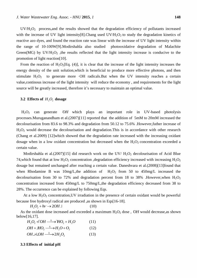
J. Water Wastewater Eng. Assoc. - HNU 2015, 1 148
UV/H2O2 process,and the results showed that the degradation efficiency of pollutants increased
with the increase of UV light intensity[8].Chang used UV/H2O2 to study the degradation kinetics of
reactive azo dyes, and found the reaction rate was linear with the increase of UV light intensity within
the range of 10-100W[9].Modirshahla also studied photooxidative degradation of Malachite
Green(MG) by UV/H2O2 ,the results reflected that the light intensity increase is conducive to the
promotion of light reaction[10].
From the reaction of H2O2[Eq. (4)], it is clear that the increase of the light intensity increases the
energy density of the unit solution,which is beneficial to produce more effective photons, and then
stimulate H2O2 to generate more ·OH radicals.But when the UV intensity reaches a certain
value,continous increase of the light intensity will reduce the economy , and requirements for the light
source will be greatly increased, therefore it’s necessary to maintain an optimal value.
3.2 Effects of 2 2H O dosage
H2O2 can generate OH which plays an important role in UV-based photolysis
processes.Muruganandham et al.(2007)[11] reported that the addition of 5mM to 20mM increased the
decolourisation from 83.6 to 98.3% and degradation from 50.12 to 75.6% .However,futher increase of
H2O2 would decrease the decolourisation and degradation.This is in accordance with other research
(Chang et al.2009) [12]which showed that the degradation rate increased with the increasing oxidant
dosage when in a low oxidant concentration but decreased when the H2O2 concentration exceeded a
certain value.
Modirshahla et al.(2007)[15] did research work on the UV/ H2O2 decolourisation of Acid Blue
74,which found that at low H2O2 concentration ,degradation efficiency increased with increasing H2O2
dosage but remained unchanged after reaching a certain value. Daneshvara et al.(2008)[13]found that
when Rhodamine B was 10mg/L,the addition of H2O2 from 50 to 450mg/L increased the
decolourisation from 30 to 72% and degradation percent from 18 to 38% .However,when H2O2
concentration increased from 450mg/L to 750mg/L,the degradation efficiency decreased from 38 to
28%. The occurrence can be explained by following Eqs.
At a low H2O2 concentration,UV irradiation in the presence of certain oxidant would be powerful
because free hydroxyl radical are produced ,as shown in Eqs[16-18].
2 2 2H O h OH (10)
As the oxidant dose increased and exceeded a maximum H2O2 dose , OH would decrease,as shown
below[16,17].
2 2 2 2
kH O OH HO H O (11)
2 2 2
kOH HO H O O (12)
2 22kOH OH H O (13)
3.3 Effects of initial pH
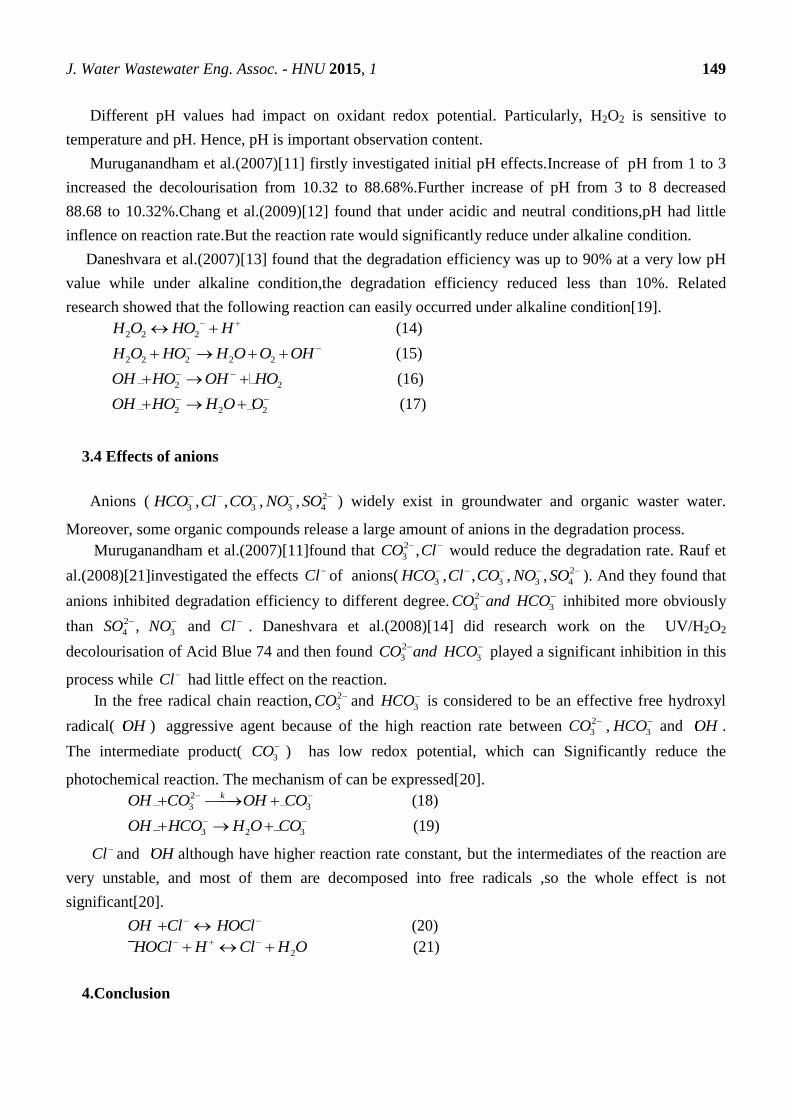
J. Water Wastewater Eng. Assoc. - HNU 2015, 1 149
Different pH values had impact on oxidant redox potential. Particularly, H2O2 is sensitive to
temperature and pH. Hence, pH is important observation content.
Muruganandham et al.(2007)[11] firstly investigated initial pH effects.Increase of pH from 1 to 3
increased the decolourisation from 10.32 to 88.68%.Further increase of pH from 3 to 8 decreased
88.68 to 10.32%.Chang et al.(2009)[12] found that under acidic and neutral conditions,pH had little
inflence on reaction rate.But the reaction rate would significantly reduce under alkaline condition.
Daneshvara et al.(2007)[13] found that the degradation efficiency was up to 90% at a very low pH
value while under alkaline condition,the degradation efficiency reduced less than 10%. Related
research showed that the following reaction can easily occurred under alkaline condition[19].
2 2 2H O HO H (14)
2 2 2 2 2H O HO H O O OH (15)
2 2OH HO OH HO (16)
2 2 2OH HO H O O (17)
3.4 Effects of anions
Anions ( 2
3 3 3 4, , , ,HCO Cl CO NO SO ) widely exist in groundwater and organic waster water.
Moreover, some organic compounds release a large amount of anions in the degradation process.
Muruganandham et al.(2007)[11]found that 2
3 ,CO Cl would reduce the degradation rate. Rauf et
al.(2008)[21]investigated the effects Cl of anions( 2
3 3 3 4, , , ,HCO Cl CO NO SO ). And they found that
anions inhibited degradation efficiency to different degree. 2
3CO and
3HCO inhibited more obviously
than 2
4 ,SO
3NO and Cl . Daneshvara et al.(2008)[14] did research work on the UV/H2O2
decolourisation of Acid Blue 74 and then found 2
3CO and
3HCO played a significant inhibition in this
process while Cl had little effect on the reaction.
In the free radical chain reaction, 2
3CO and 3HCO is considered to be an effective free hydroxyl
radical( OH ) aggressive agent because of the high reaction rate between 2
3CO , 3HCO and OH .
The intermediate product( 3CO ) has low redox potential, which can Significantly reduce the
photochemical reaction. The mechanism of can be expressed[20].
2
3 3
kOH CO OH CO (18)
3 2 3OH HCO H O CO (19)
Cl and OH although have higher reaction rate constant, but the intermediates of the reaction are
very unstable, and most of them are decomposed into free radicals ,so the whole effect is not
significant[20].
OH Cl HOCl (20)
2HOCl H Cl H O (21)
4.Conclusion
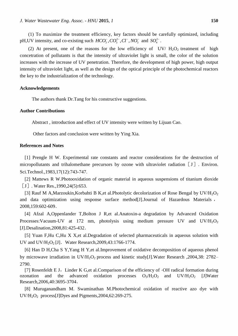
J. Water Wastewater Eng. Assoc. - HNU 2015, 1 150
(1) To maximize the treatment efficiency, key factors should be carefully optimized, including
pH,UV intensity, and co-existing such 2
3 3 3, , ,HCO CO Cl NO and 2
4SO .
(2) At present, one of the reasons for the low efficiency of UV/ H2O2 treatment of high
concetration of pollutants is that the intensity of ultraviolet light is small, the color of the solution
increases with the increase of UV penetration. Therefore, the development of high power, high output
intensity of ultraviolet light, as well as the design of the optical principle of the photochemical reactors
the key to the industrialization of the technology.
Acknowledgements
The authors thank Dr.Tang for his constructive suggestions.
Author Contributions
Abstract , introduction and effect of UV intensity were written by Lijuan Cao.
Other factors and conclusion were written by Ying Xia.
References and Notes
[1] Prengle H W. Experimental rate constants and reactor considerations for the destruction of
micropollutants and trihalomethane precursors by ozone with ultraviolet radiation[J]. Environ.
Sci.Technol.,1983,17(12):743-747.
[2] Mattews R W.Photooxidation of organic material in aqueous suspensions of titanium dioxide
[J]. Water Res.,1990,24(5):653.
[3] Rauf M A,Marzoukin,Korbahti B K,et al.Photolytic decolorization of Rose Bengal by UV/H2O2
and data optimization using response surface method[J].Journal of Hazardous Materials ,
2008,159:602-609.
[4] Afzal A,Oppenlander T,Bolton J R,et al.Anatoxin-a degradation by Advanced Oxidation
Processes:Vacuum-UV at 172 nm, photolysis using medium pressure UV and UV/H2O2
[J].Desalination,2008,81:425-432.
[5] Yuan F,Hu C,Hu X X,et al.Degradation of selected pharmaceuticals in aqueous solution with
UV and UV/H2O2 [J].Water Research,2009,43:1766-1774.
[6] Han D H,Cha S Y,Yang H Y,et al.Improvement of oxidative decomposition of aqueous phenol
by microwave irradiation in UV/H2O2 process and kinetic study[J].Water Research ,2004,38: 2782–
2790.
[7] Rosenfeldt E J,Linder K G,et al.Comparison of the efficiency of ·OH radical formation during
ozonation and the advanced oxidation processes O3/H2O2 and UV/H2O2 [J]Water
Research,2006,40:3695-3704.
[8] Muruganandham M. Swaminathan M.Photochemical oxidation of reactive azo dye with
UV/H2O2 process[J]Dyes and Pigments,2004,62:269-275.
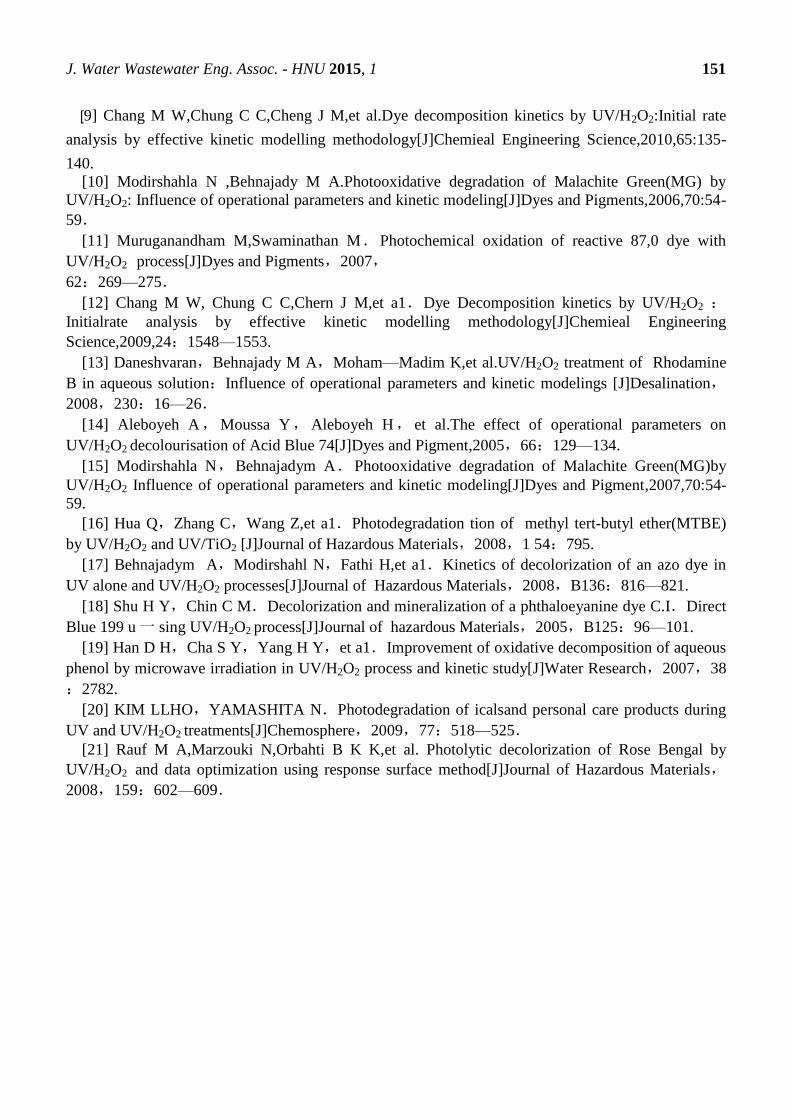
J. Water Wastewater Eng. Assoc. - HNU 2015, 1 151
[9] Chang M W,Chung C C,Cheng J M,et al.Dye decomposition kinetics by UV/H2O2:Initial rate
analysis by effective kinetic modelling methodology[J]Chemieal Engineering Science,2010,65:135-
140.
[10] Modirshahla N ,Behnajady M A.Photooxidative degradation of Malachite Green(MG) by
UV/H2O2: Influence of operational parameters and kinetic modeling[J]Dyes and Pigments,2006,70:54-
59.
[11] Muruganandham M,Swaminathan M.Photochemical oxidation of reactive 87,0 dye with
UV/H2O2 process[J]Dyes and Pigments,2007,
62:269—275.
[12] Chang M W, Chung C C,Chern J M,et a1.Dye Decomposition kinetics by UV/H2O2 :Initialrate analysis by effective kinetic modelling methodology[J]Chemieal Engineering
Science,2009,24:1548—1553.
[13] Daneshvaran,Behnajady M A,Moham—Madim K,et al.UV/H2O2 treatment of Rhodamine
B in aqueous solution:Influence of operational parameters and kinetic modelings [J]Desalination,
2008,230:16—26.
[14] Aleboyeh A,Moussa Y,Aleboyeh H, et al.The effect of operational parameters on
UV/H2O2 decolourisation of Acid Blue 74[J]Dyes and Pigment,2005,66:129—134.
[15] Modirshahla N,Behnajadym A.Photooxidative degradation of Malachite Green(MG)by
UV/H2O2 Influence of operational parameters and kinetic modeling[J]Dyes and Pigment,2007,70:54-
59.
[16] Hua Q,Zhang C,Wang Z,et a1.Photodegradation tion of methyl tert-butyl ether(MTBE)
by UV/H2O2 and UV/TiO2 [J]Journal of Hazardous Materials,2008,1 54:795.
[17] Behnajadym A,Modirshahl N,Fathi H,et a1.Kinetics of decolorization of an azo dye in
UV alone and UV/H2O2 processes[J]Journal of Hazardous Materials,2008,B136:816—821.
[18] Shu H Y,Chin C M.Decolorization and mineralization of a phthaloeyanine dye C.I.Direct
Blue 199 u 一 sing UV/H2O2 process[J]Journal of hazardous Materials,2005,B125:96—101.
[19] Han D H,Cha S Y,Yang H Y,et a1.Improvement of oxidative decomposition of aqueous
phenol by microwave irradiation in UV/H2O2 process and kinetic study[J]Water Research,2007,38
:2782.
[20] KIM LLHO,YAMASHITA N.Photodegradation of icalsand personal care products during
UV and UV/H2O2 treatments[J]Chemosphere,2009,77:518—525.
[21] Rauf M A,Marzouki N,Orbahti B K K,et al. Photolytic decolorization of Rose Bengal by
UV/H2O2 and data optimization using response surface method[J]Journal of Hazardous Materials,
2008,159:602—609.

WWEA College of Civil Engineering
312 South Building
Hunan University
Changsha
Hunan 410082
China WWEA © 2015
Water and Wastewater Engineering Association at
Hunan University
Top Related