


![DRAFT EUROPEAN TELECOMMUNICATION April 1996 … · the synchronous digital hierarchy (SDH)". [3] ITU-T Recommendation G.708: "Network node interface for the synchronous digital hierarchy".](https://static.fdocuments.net/doc/165x107/5c87fe1e09d3f2df188d00a1/draft-european-telecommunication-april-1996-the-synchronous-digital-hierarchy.jpg)


Languages
Pages
Legal

Introduction to the Synchronous Digital Hierarchy (SDH)

The History of Digital Transmission
’70s - introduction of PCM into Telecom networks32 PCM streams are Synchronously Multiplexed to 2.048 Mbit/s (E1)Multiplexing to higher rates via PDH1985 Bellcore proposes SONET 1988 SDH standard introduced.
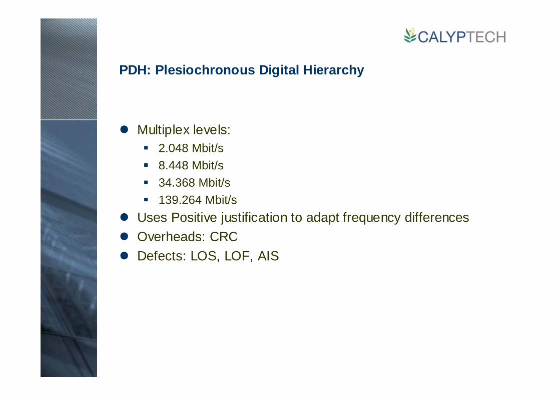
PDH: Plesiochronous Digital Hierarchy
Multiplex levels:2.048 Mbit/s8.448 Mbit/s34.368 Mbit/s139.264 Mbit/s
Uses Positive justification to adapt frequency differencesOverheads: CRCDefects: LOS, LOF, AIS
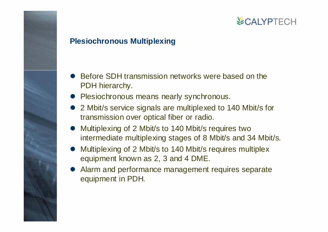
Plesiochronous Multiplexing
Before SDH transmission networks were based on the PDH hierarchy.Plesiochronous means nearly synchronous.2 Mbit/s service signals are multiplexed to 140 Mbit/s for transmission over optical fiber or radio.Multiplexing of 2 Mbit/s to 140 Mbit/s requires two intermediate multiplexing stages of 8 Mbit/s and 34 Mbit/s.Multiplexing of 2 Mbit/s to 140 Mbit/s requires multiplex equipment known as 2, 3 and 4 DME.Alarm and performance management requires separate equipment in PDH.
397.2 Mbit/s
32.084 Mbit/s
97.728 Mbit/s
6.312 Mbit/s
274.176 Mbit/s
6.312 Mbit/s
44.738 Mbit/s
1.544 Mbit/s
139.264Mbit/s
8.448 Mbit/s
34.368 Mbit/s
2.048 Mbit/s
Japan NorthAmerica
Europe
x 4
x 4
x 4
x 4x 4
x 5
x 3
x 4
x 7
x 6
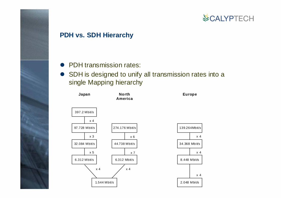
PDH vs. SDH Hierarchy
PDH transmission rates:SDH is designed to unify all transmission rates into a single Mapping hierarchy
1
64
2DME
3DME
2DME
3DME2
DME
4DME
2 Mb it/s 8 Mbi t/s 34 Mb it/s 140 Mbi t/s
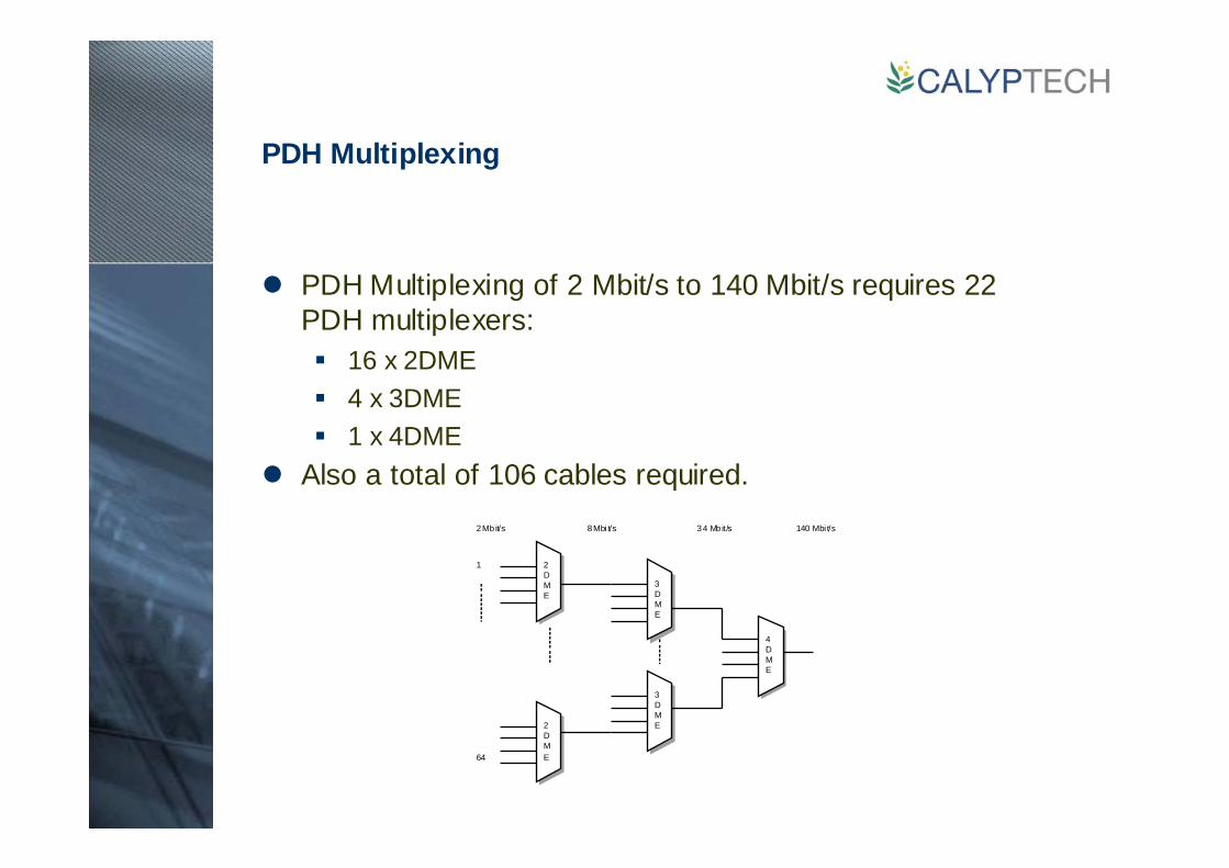
PDH Multiplexing
PDH Multiplexing of 2 Mbit/s to 140 Mbit/s requires 22 PDH multiplexers:
16 x 2DME4 x 3DME1 x 4DME
Also a total of 106 cables required.

PDH Add/Drop
If a small number of 2 Mbit/s streams passing through a site need to be dropped then in PDH this requires large amount of equipment to multiplex down to 2Mbit/s.
What is SDH?
The basis of Synchronous Digital Hierarchy (SDH) is synchronous multiplexing - data from multiple tributary sources is byte interleaved.In SDH the multiplexed channels are in fixed locations relative to the framing byte.Demultiplexing is achieved by gating out the required bytes from the digital stream. This allows a single channel to be ‘dropped’ from the data stream without demultiplexing intermediate rates as is required in PDH.
SDH Rates
SDH is a transport hierarchy based on multiples of 155.52 Mbit/sThe basic unit of SDH is STM-1:
STM-1 = 155.52 Mbit/s
STM-4 = 622.08 Mbit/s
STM-16 = 2588.32 Mbit/s
STM-64 = 9953.28 Mbit/sEach rate is an exact multiple of the lower rate therefore the hierarchy is synchronous.
STM-N AUG
xN
x1
x3
AU-4 VC-4
TUG-3
AU-3 VC-3
TUG-2
TU-3
C-4
C-3
TU-2 VC-2 C-2
TU-12 VC-12 C12
TU-11 VC-11 C-11
VC-3
x3
x7
x7
x1
x1
x3
x4
HOP
LOP
139264 kb/s
44736 kb/s(DS3)
34368 kb/s
6312 kb/s(DS2)
2048 kb/s
1544 kb/s(DS1)
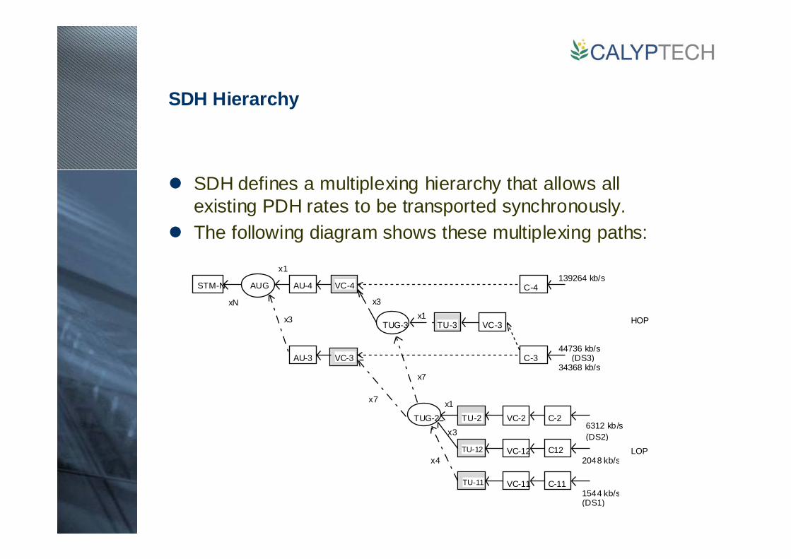
SDH Hierarchy
SDH defines a multiplexing hierarchy that allows all existing PDH rates to be transported synchronously.The following diagram shows these multiplexing paths:
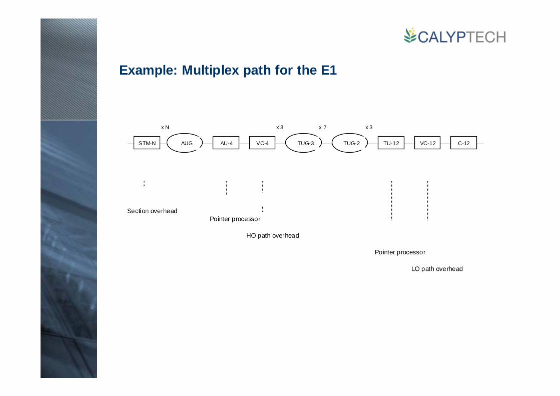
Example: Multiplex path for the E1
Section overheadPointer processor
HO path overhead
Pointer processor
LO path overhead
AUG AU-4 VC-4 TUG-2TUG-3 TU-12 VC-12 C-12STM-N
x N x 7x 3 x 3
Transport of PDH payloads
SDH is essentially a transport mechanism for carrying a large number of PDH payloads.A mechanism is required to map PDH rates into the STM frame.This function is performed by the container (C).A PDH channel must be synchronised before it can be mapped into a container.The synchroniser adapts the rate of an incoming PDH signal to SDH rate.
SDH
PDH
Bit stuffing
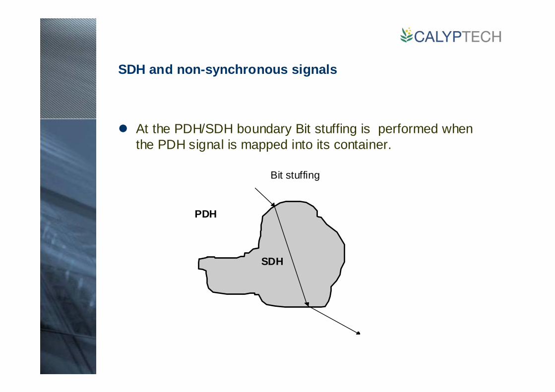
SDH and non-synchronous signals
At the PDH/SDH boundary Bit stuffing is performed when the PDH signal is mapped into its container.

SDH virtual Containers
Once a container has been created, path overhead byte are added to create a virtual container.Path overheads contain alarm, performance and other management information.A path through an SDH network exists from the point where a PDH signal is put into a container to where the signal is recovered from the container.The path overheads travel with the container over the path.

T1517990-95
VC-4
AU-4
AUG
STM-N
Container-4
VC-4
SOH AUG AUG
AU-4 PTR
Container-4VC-4 POH
AU-4 PTR VC-4
Logical association
Physical association
NOTE – Unshaded areas are phase aligned. Phase alignment between the unshaded and shaded areas is defined by thepointer (PTR) and is indicated by the arrow.
Mapping Virtual Containers
C-4 container being mapped into an STM frame via a VC-4 virtual container

2 Mbit/s PCM30 frame structure
The SDH frame rate is inherited from PCM.As with PCM, the SDH has 8 bits per time slot.As with PCM, the SDH frame rate in 125 us per frame.The following diagram shows the PCM30 frame:
TS31TS30 TS0TS17TS16TS15TS1TS0
125 us
T1518000-95
4
3
1
9
5
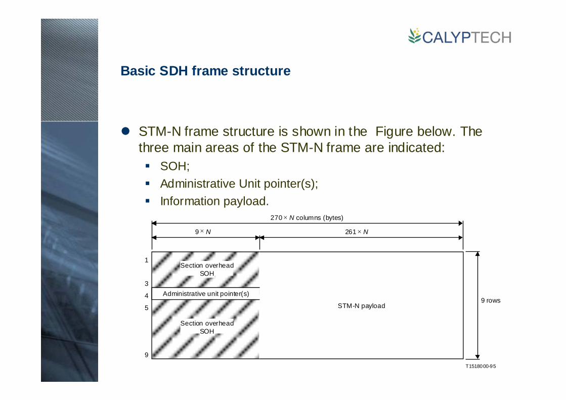
270 × N columns (bytes)
9 × N 261 × N
STM-N payload9 rows
Section overheadSOH
Section overheadSOH
Administrative unit pointer(s)
Basic SDH frame structure
STM-N frame structure is shown in the Figure below. The three main areas of the STM-N frame are indicated:
SOH;Administrative Unit pointer(s);Information payload.
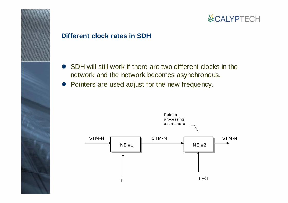
f f +δf
NE #1NE #1 NE #2STM-N STM-N STM-N
Pointerprocessingocurrs here
Different clock rates in SDH
SDH will still work if there are two different clocks in the network and the network becomes asynchronous.Pointers are used adjust for the new frequency.
N 1
K 3
F 3
H 4
F 2
G 1
C 2
B 3
J 1
T 1 5 18 2 3 0 - 95
V C -4 -X c
3
1
5
1
R S O H
M SO H
X- 1
C - 4 -X c
A U -n P T R s
S T M -NN × 2 7 0 b yte s
N × 2 6 1 b yte s
X × 2 6 1 b y te s
F ix e dstu f f
P T R P o in te r
N × 9
X × 2 6 0
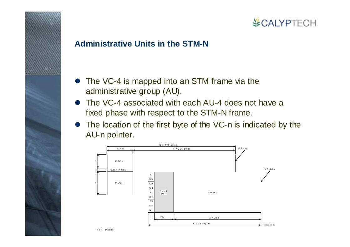
Administrative Units in the STM-N
The VC-4 is mapped into an STM frame via the administrative group (AU).The VC-4 associated with each AU-4 does not have a fixed phase with respect to the STM-N frame.The location of the first byte of the VC-n is indicated by the AU-n pointer.
Tributary Units in a VC-4
The VC-4 can carry a container -4 (C-4). The C4 carries a 140 Mbit/s PDH signal.The VC-4 forms what is known as an high order path.If lower speed PDH signals need to be transported these are mapped into a tributary unit (TU).The TUs are then multiplexed into a VC-4.The VC-n associated with each TU-n does not have a fixed phase relationship with respect to the start of the VC-4.The TU-n pointer is in a fixed location in the VC-4 and the location of the first byte of the VC-n is indicated by the TU-n pointer.
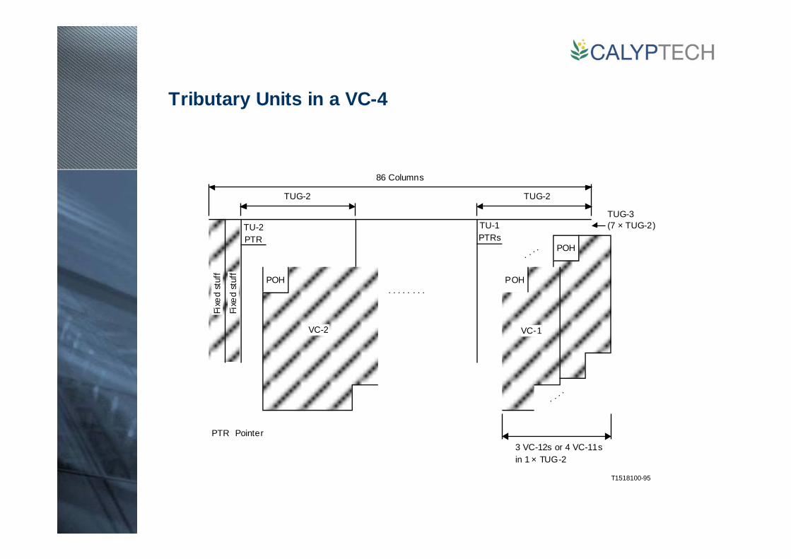
Tributary Units in a VC-4
T1518100-95
. . . .
. . . .
. . . . . . . .
TUG-2 TUG-2
POH POH
POH
VC-2 VC-1
TUG-3(7 × TUG-2)
3 VC-12s or 4 VC-11sin 1 × TUG-2
TU-2PTR
TU-1PTRs
86 Columns
PTR Pointer
Fixe
d st
uff
Fixe
d st
uff

T1523020-96
V 5
R R R R R R R R
R R R R R R R R
J 2
C1 C2 O O O O R R
R R R R R R R R
N 2
R R R R R R R R
K 4
C1 C2 R R R R R S 1
S 2 D D D D D D D
C1 C2 O O O O R R
R R R R R R R R
32 bytes
32 bytes
32 bytes
31 bytes
140bytes
Data bitFixed stuff bitOverhead bitJustification opportunity bitJustification control bit
DROSC
BIP-2 1 2
REI 3
RFI 4
Signal Label 5 6 7
RDI 8
Tributary units
2 Mbit/s are mapped asynchronously into a VC-12.VC-12s are distributed over four frames known as a VC multiframe.The figure shows this over a period of 500 µs.
V5 byte:

STM Section Overheads
Nine rows of nine bytes at the front of the SDH frame form the section overhead.The first three rows are the regenerator section overhead.The last six rows are the multiplex section overhead.
A1 A1 A1 A2 A2 A2 J0
B1 E1 E1 F1
D1 D2 D3
B2 B2 B2 K1 K2
D4 D5 D6
D7 D8 D9
D10 D11 D12
S1 Z1 Z1 Z2 Z2 M1 E2E2
9 Bytes
9 rows
RSOH
MSOH
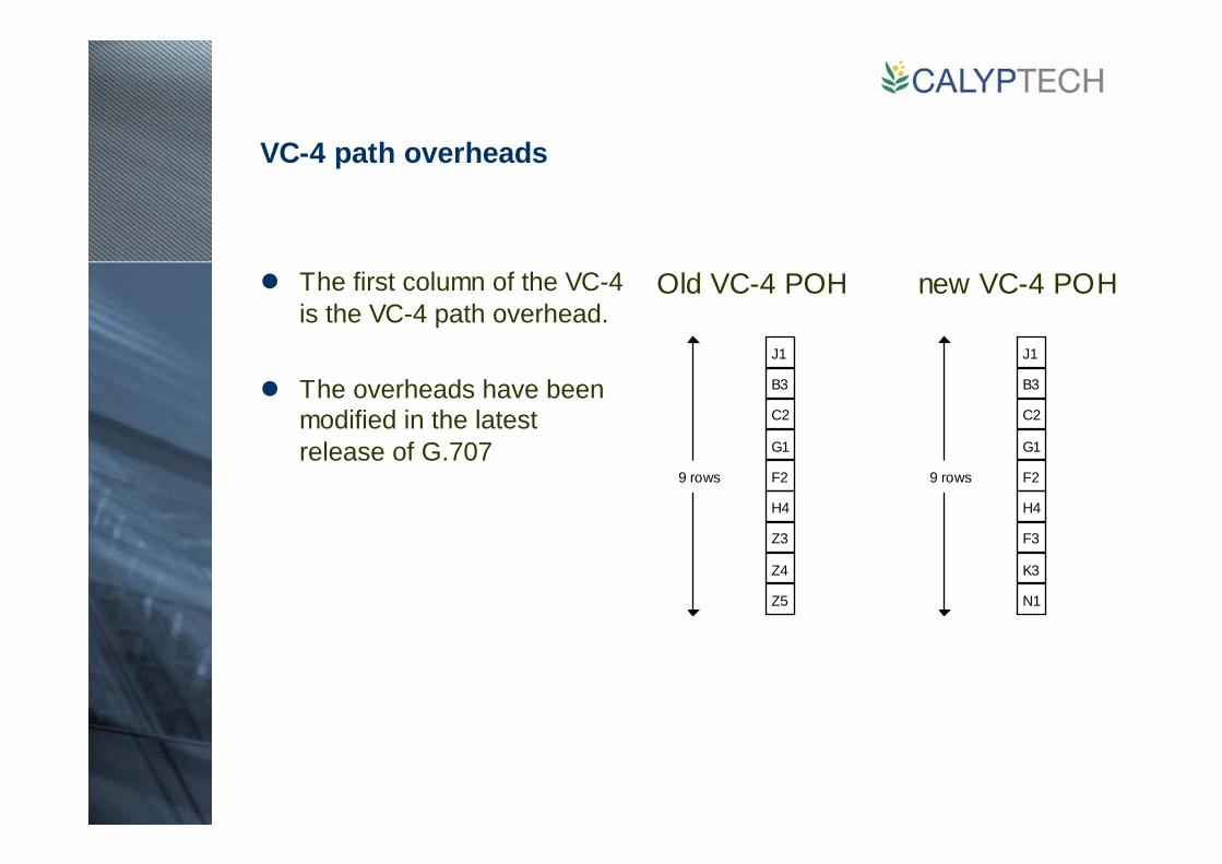
VC-4 path overheads
The first column of the VC-4 is the VC-4 path overhead.
The overheads have been modified in the latest release of G.707
Old VC-4 POH new VC-4 POH
J1
B3
C2
F2
H4
Z3
Z5
G1
9 rows
Z4
J1
B3
C2
F2
H4
F3
N1
G1
9 rows
K3

VC-12 overhead
The first byte of the VC-12 is the VC-12 path overhead.
The VC-12 frame is spread over four frames to form a VC-12 multiframe.
Each of the four frames in the multiframe contains an overhead byte.
The overheads have been modified in the latest release of G.707
V5
J2
Z6
Z7
VC-12
125 us35 bytes
125 us35 bytes
125 us35 bytes
125 us35 bytes
V5
J2
N2
K4
VC-12
125 us35 bytes
125 us35 bytes
125 us35 bytes
125 us35 bytes
old VC-12 OH new VC-12 OH

V5 Byte
The bits in the V5 byte are allocated as follows:
BIP-2 1 2
REI 3
RFI 4
Signal Label 5 6 7
RDI 8
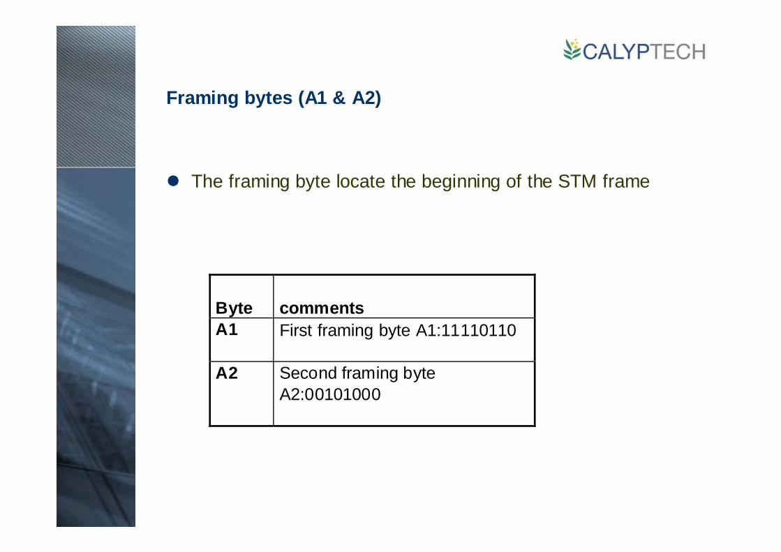
Framing bytes (A1 & A2)
The framing byte locate the beginning of the STM frame
Byte commentsA1 First framing byte A1:11110110
A2 Second framing byteA2:00101000
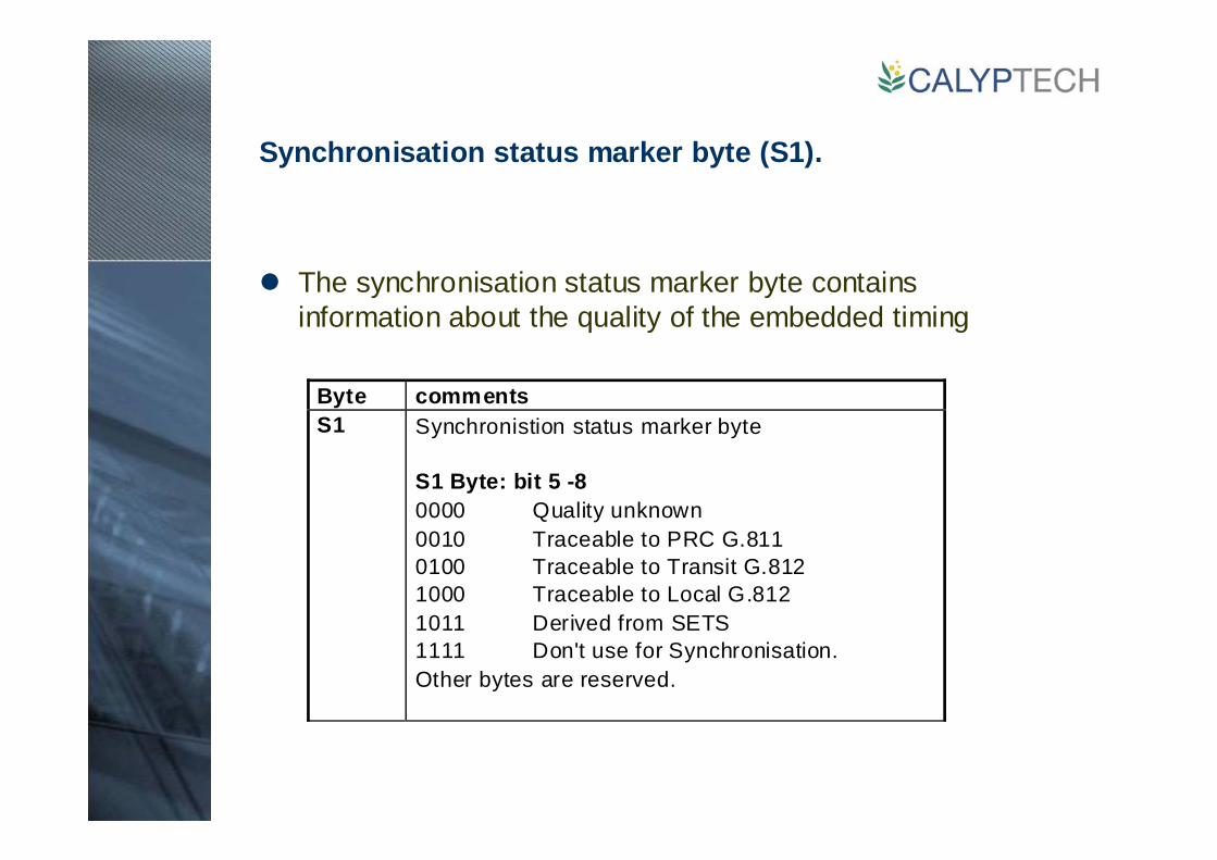
Synchronisation status marker byte (S1).
The synchronisation status marker byte contains information about the quality of the embedded timing
Byte commentsS1 Synchronistion status marker byte
S1 Byte: bit 5 -80000 Quality unknown0010 Traceable to PRC G.8110100 Traceable to Transit G.8121000 Traceable to Local G.8121011 Derived from SETS1111 Don't use for Synchronisation.Other bytes are reserved.

Bit interleaved parity (B1, B2, B3)
The BIP is calculated over the previous frame/multiframe
Regen OH
Mux OH
VC-4
9 columns 261 columns
9 rowsPath
OH
V5 bits 1 & 2: TU-12 frame
B1 parity - Entire frame B2 parity: Mux OH + AU-4
Regen OH
Mux OH
9 columns 261 columns
9 rows
B3 parity - Virtual Container
PayloadVC-4
AU-4
Regen OH
Mux OH
VC-4
9 columns 261 columns
9 rowsPath
OH
Payload
VC-4
AU-4
Regen OH
Mux OH
9 columns 261 columns
9 rows AU-4AU-4
TU-12 pointer
Path OH
TU-12
Payload
BIP Bits & Bytes Coverage
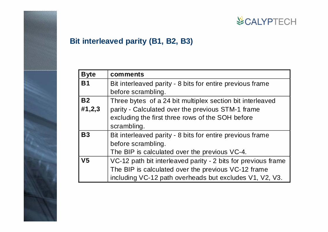
Bit interleaved parity (B1, B2, B3)
Byte commentsB1 Bit interleaved parity - 8 bits for entire previous frame
before scrambling.B2#1,2,3
Three bytes of a 24 bit multiplex section bit interleavedparity - Calculated over the previous STM-1 frameexcluding the first three rows of the SOH beforescrambling.
B3 Bit interleaved parity - 8 bits for entire previous framebefore scrambling.The BIP is calculated over the previous VC-4.
V5 VC-12 path bit interleaved parity - 2 bits for previous frameThe BIP is calculated over the previous VC-12 frameincluding VC-12 path overheads but excludes V1, V2, V3.
Orderwire (E1 & E2)
The E byte carry the orderwire channels. The relief byte is used for ring protection
E1 – Regenerator section orderwire
E2 – Multiplex section orderwire

DCC channels (D1 to D3 and D4 to D12)
The DCC channels are used Element Management Software to pass management information between sites.
Byte commentsD1 toD3
Regenerator section data communications channel(DCC)The D1 to D3 bytes are a 192 kbit/s DCC channel.
D4 toD12
Multiplex section data communications channelThe D4 to D12 bytes are a 576 kbit/s DCC channel.
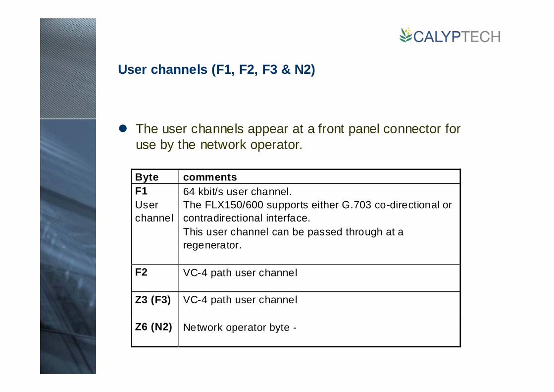
User channels (F1, F2, F3 & N2)
The user channels appear at a front panel connector for use by the network operator.
Byte commentsF1Userchannel
64 kbit/s user channel.The FLX150/600 supports either G.703 co-directional orcontradirectional interface.This user channel can be passed through at aregenerator.
F2 VC-4 path user channel
Z3 (F3) VC-4 path user channel
Z6 (N2) Network operator byte -
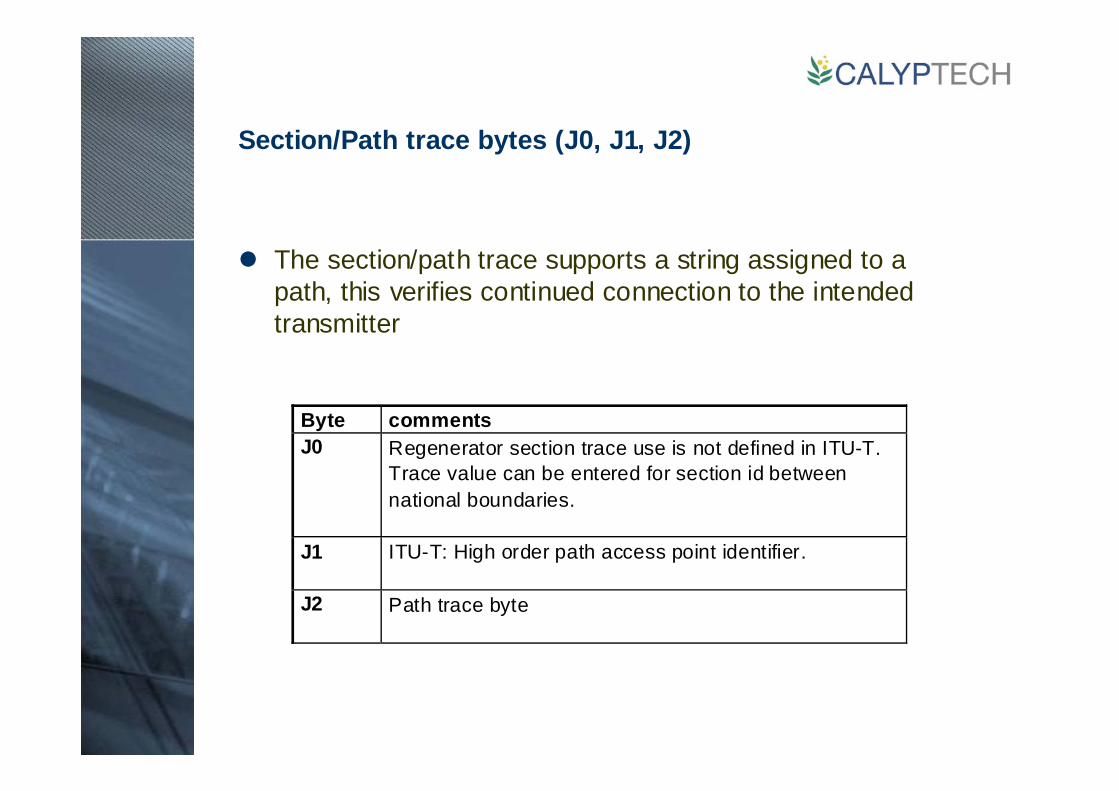
Section/Path trace bytes (J0, J1, J2)
The section/path trace supports a string assigned to a path, this verifies continued connection to the intended transmitter
Byte commentsJ0 Regenerator section trace use is not defined in ITU-T.
Trace value can be entered for section id betweennational boundaries.
J1 ITU-T: High order path access point identifier.
J2 Path trace byte
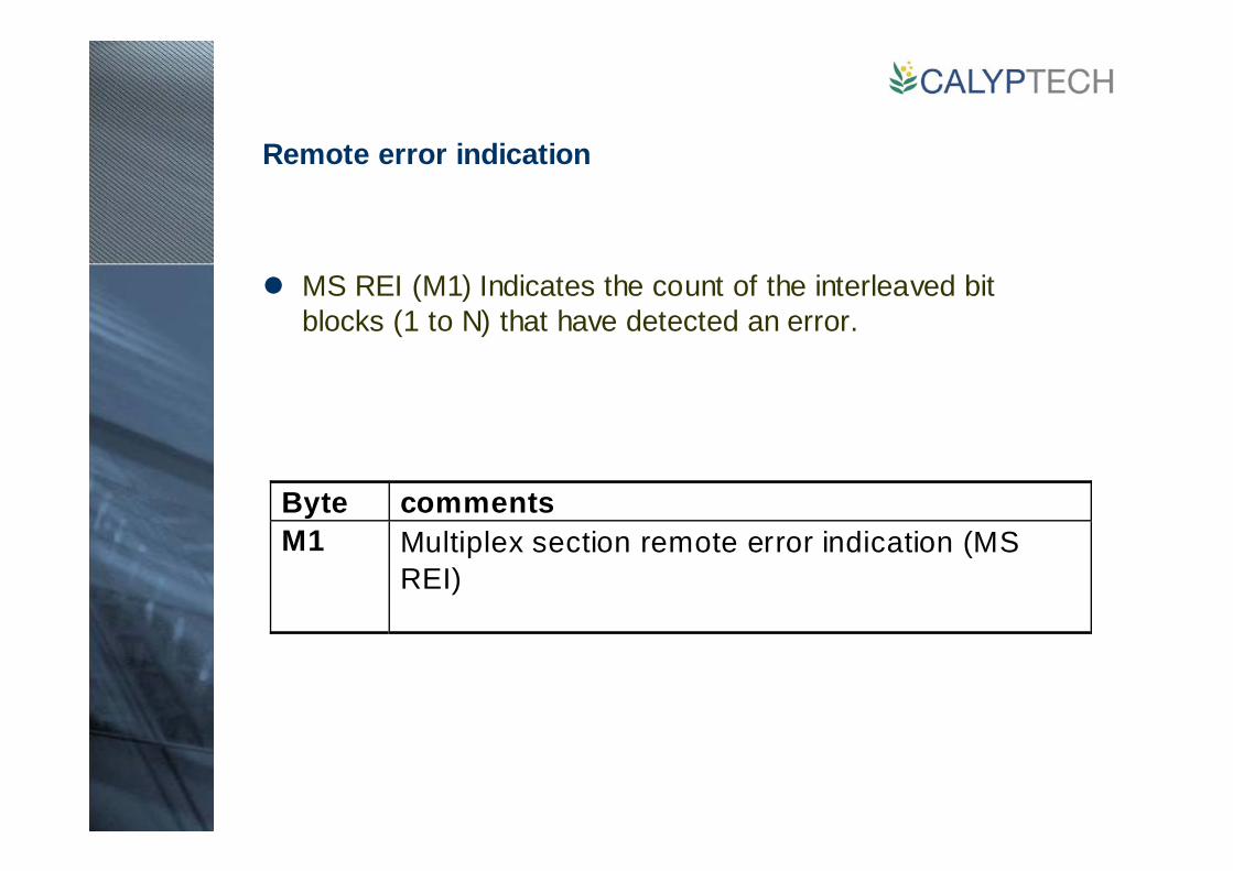
Remote error indication
MS REI (M1) Indicates the count of the interleaved bit blocks (1 to N) that have detected an error.
Byte commentsM1 Multiplex section remote error indication (MS
REI)

High order path management
Signal label (C2)
Path Status
Multiframe Pointer
Byte commentsC2 Signal label: This byte indicates the composit ion of the
VC-4.
Byte commentsG1 Path status byte. This byte is sent from the receiver
back to the originator.
Byte commentsH4 VC-4 multiframe pointer.
Indicates the multiframe position indicator for the VC-12

Low order path management
The VC-12 path overhead signals are held in the V5 byte.
Byte CommentsV5bit 3
Remote error indication (REI): set to one if oneor more error is detected at receiver in the BIP-2.Standard implementation on FLX and FLM
V5bit 4
Remote failure indication (RFI). Set to one if afailure is declared .
V5bit 5-7
VC-12 signal label.
V5bit 8
VC-12 path remote defect indication (RDI) Set to1 if an AIS or a signal failure condition isreceived.
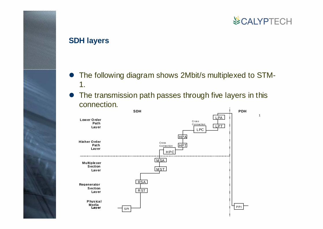
SDH layers
The following diagram shows 2Mbit/s multiplexed to STM-1.The transmission path passes through five layers in this connection.
1
P hys ica lMedia
Lay er
Multiple xerS ection
Lay er
RegeneratorS ection
Lay er
Cr os sConnec tion
Higher O rderPath
Lay er
Low er O rderPath
Lay er
CrossConnec tion
RST
RSA
MSA
MST
HPT
HPA
LPA
LPT
SPI PPI
LPC
HPC
SDH
Lay er
PDH
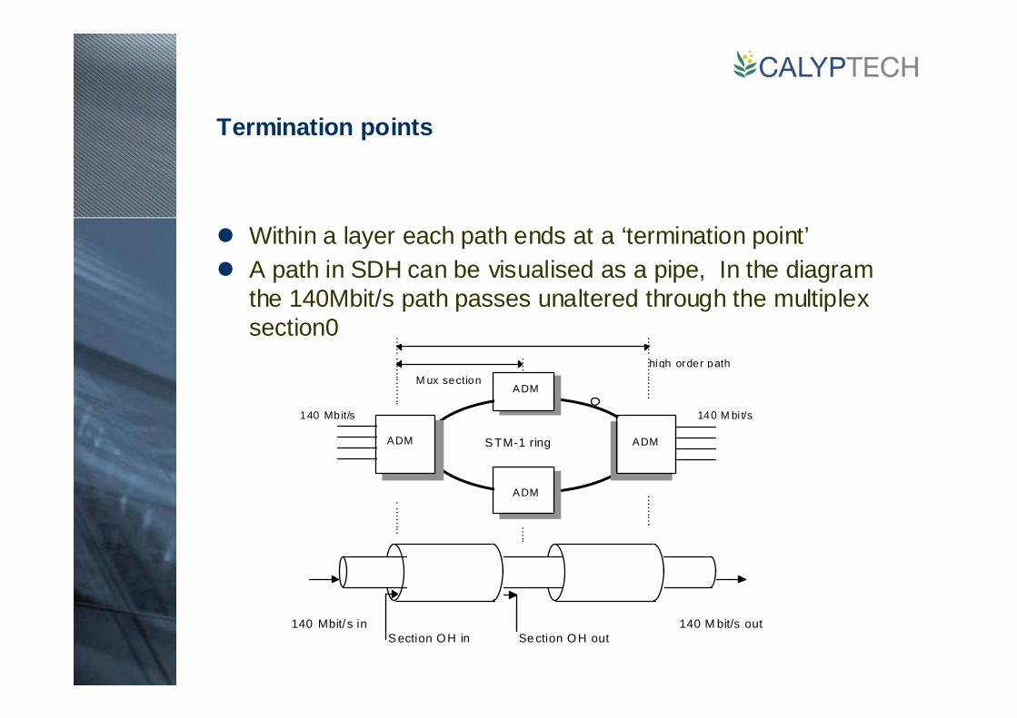
Termination points
Within a layer each path ends at a ‘termination point’A path in SDH can be visualised as a pipe, In the diagram the 140Mbit/s path passes unaltered through the multiplex section0
M ux section
ADM
high order path
140 Mbit/s
S TM-1 ringADM
140 M bi t/s
ADM
ADM
140 Mbit/ s in 140 M bit/s outS ection OH in Se ction OH out
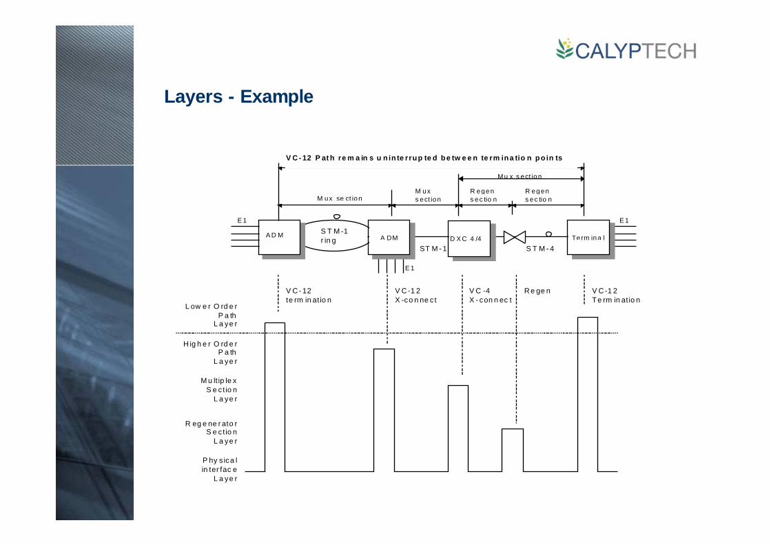
Layers - Example
ST M - 1
M ux se ct ion
Mu x s ect ion
R egens ec tio n
Term ina lD X C 4 /4A DM
R egens ec tio n
M uxs ect ion
E 1 E 1S T M -1r in g
S T M - 4
E 1
A D M
V C -4X - con n ec t
V C - 12te rm in at io n
V C -1 2X -co n ne c t
V C -1 2Te rm in at io n
L ow e r O rd e rP a th
L a ye r
H ig h e r O rd e rP a th
L a ye r
M u lt ip le xS e c t io n
L a ye r
R eg e ne r ato rS e c t io n
L a ye r
P hy s ica lin ter fac e
L a ye r
V C - 12 P at h re m a in s u n in te rrup te d be tw e e n te rm ina tio n po in ts
R e ge n

Alarms and layers
Each defect indication is associated with a layer
Mux section
ADM
Low order path
E1 E1STM-1ring
ADM
MultiplexerSection
Layer
RegeneratorSection
Layer
Higher OrderPath
Layer
Lower OrderPath
Layer
STM PhysicalMedia
LayerLayer
PDH PhysicalIn terface
LayerLO S
LO F
LO S
RS-BIP
MS-AIS
MS-RDIAU-AISAU-LO P
VC-4 REIVC-4 RDIVC-4 LOM
VC-12 AISVC-12 LO PVC-12 BIPVC-12 REI
VC-12 RDIVC-12 RFI
MS-BIP
VC-4 BIP
LOS
LOF
LOS
RS-BIP
MS-AIS
MS-RDIAU-AISAU-LOP
VC-4 RE IVC-4 RDIVC-4 LOM
VC-12 AISVC-12 LOPVC-12 BIPVC-12 REI
VC-12 RDIVC-12 RFI
MS-BIP
VC-4 BIP
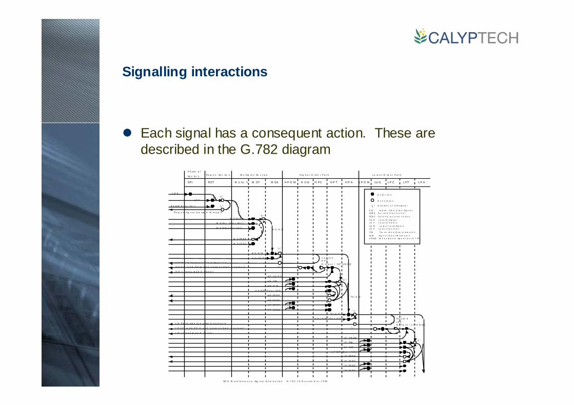
Signalling interactions
Each signal has a consequent action. These are described in the G.782 diagram
SPI RST N o t e 1 M ST M SA H P O M H U G H PC H P T H P A L P O M LU G L P C L PT L P A
Lo w e r O rd e r P a t hH ig h e r O rd e r P a t hM u ltip le x Se c t io nR e g e n Se c tio nP h ys ic a l
Se c tio n
L O P L o s s o f p o i n te r
FEB E Fa r e n d b l o c k e rr o r
L O S L o s s o f s i g n a lL O F L o s s o f fr a m e
"1 "
SD H M a in t e n a n c e Sig n a l In t e r a c t io n G .7 8 2 1 0 N o v e m b e r 1 9 92
L O S
L O M L o ss o f m u l t i fra m e
A IS A l a rm In d i c a t io n Si g n a l
D e te c ti o n
G e n e ra ti o n
In s e rt i o n o f A IS s i g n a l
FER F Fa r e n d re c e i v e f a i l u r e
SL M Si g n a l l a b e l M i s m a tc h
TIM T ra c e i d e n ti f i e r m i s m a tc h
U N EQ Un e q u ip p e d si g n a l p e r G 7 0 9
"1 "
"1 "
"1 "
"1 "
"1 "
" 1 "
" 1 "
"1 "
"1 "
LO F
R S- B IP E r ro r ( B 1 )
R e g e n s ig n a l p a sse d th ro u g h
M S- A I S
M S- Ex c Er ro r (B 2 )
M S- B IP E rr o r ( B 2 )
M S- FE R F
M S- FE R F
A U - A IS
A U - A IS
A U - LO P
H O P a t h s ig n a l p a sse d th r o u g h
H O V C w it h P O H a n d u n sp e c if ie d p a y lo a d
H O u n e q u ip p e d s ig n a l
H P - U N E Q
H P - TIM
H P - SL M
H P -B IP E rr o r ( B 3)
H P - FE R F
H P - FE R F
H P - FE B E
H P - FE B E
U n u se dH P CO u t p u t / H P - U N E Q
TU - A IS
TU - A IS
H P - LO M / TU -L O P
L O P a t h s ig n a l p a sse d t h r o u g h
L O V C w it h P O H a n d u n sp e c if ie d p a y lo a d
L O u n e q u ip p e d sig n a l
LP - U N EQ
LP - TIM
LP - SLM
L P -B IP Er ro r ( V 5 )
LP - FE R F
LP - FE R F
LP - FE B E
LP - FE B E
U n u se dLP CO u t p u t / L P -U N EQ
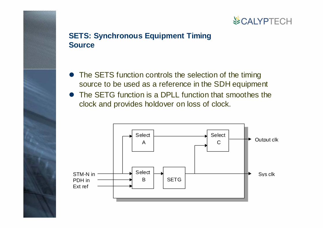
SETS: Synchronous Equipment Timing Source
The SETS function controls the selection of the timing source to be used as a reference in the SDH equipmentThe SETG function is a DPLL function that smoothes the clock and provides holdover on loss of clock.
Select A
Select B
Select C
SETGSTM-N inPDH inExt ref
Output clk
Sys clk
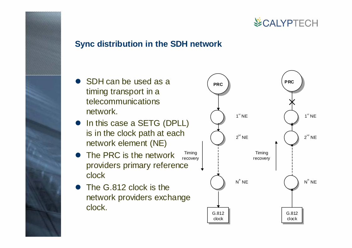
Sync distribution in the SDH network
SDH can be used as a timing transport in a telecommunications network.In this case a SETG (DPLL) is in the clock path at each network element (NE)The PRC is the network providers primary reference clockThe G.812 clock is the network providers exchange clock.
PRC PRC
1st NE
2nd
NE
Nth NE
1st NE
2nd
NE
Nth NE
Timingrecovery
Timingrecovery
G.812clock
G.812clock
Top Related