


Languages
Pages
Legal

INSTRUCTIONS Outboard Engines
Instruction for Connecting the Mechanical Control Module Conversion
(MCM) Box to Non-BRP Branded Remote Controls
SAFETY INFORMATION
The following symbols and/or signal words maybe used in this document:
These safety alert signal words mean:
ATTENTION!
BECOME ALERT!
YOUR SAFETY IS INVOLVED!
For safety reasons, this kit must be installed by an
authorized Evinrude® dealer. This instructionsheet is not a substitute for work experience.Additional helpful information may be found inother service literature.
DO NOT perform any work until you have readand understood these instructions completely.
Torque wrench tightening specifications muststrictly be adhered to.
Should removal of any locking fastener (lock tabs,locknuts, or patch screws) be required, alwaysreplace with a new one.
When replacement parts are required, use Evin-
rude/Johnson® Genuine Parts or parts with equiv-alent characteristics, including type, strength andmaterial. Use of substandard parts could result ininjury or product malfunction.
Always wear EYE PROTECTION AND APPRO-PRIATE GLOVES when using power tools.
Unless otherwise specified, engine must be OFF(not running) when performing this work.
Always be aware of parts that can move, such asflywheels, propellers, etc.
Some components may be HOT. Always wait forengine to cool down before performing work.
If you use procedures or service tools that are notrecommended in this instruction sheet, YOUALONE must decide if your actions might injurepeople or damage the outboard.
This instruction sheet may be translated into otherlanguages. In the event of any discrepancy, theEnglish version shall prevail.
TO THE INSTALLER: Give this sheet and theoperating instructions to the owner. Advise theowner of any special operation or maintenanceinformation contained in the instructions.
TO THE OWNER: Save these instructions in yourowner’s kit. This sheet contains informationimportant for the use and maintenance of yourengine.
� DANGERIndicates a hazardous situation which, if notavoided, will result in death or serious injury.
� WARNINGIndicates a hazardous situation which, if notavoided, could result in death or seriousinjury
� CAUTIONIndicates a hazardous situation which, if notavoided, could result in minor or moderatepersonal injury.
NOTICEIndicates an instruction which, if not fol-lowed, could severely damage engine compo-nents or other property.
1 of 4
*359033*Printed in the United States.© 2015 BRP US Inc. All rights reserved.TM, ® and the BRP logo are registered trademarks of Bombardier Recreational Products Inc. or its affiliates.
Non-BRP branded mechanical remote controlscan be used with the MCM Conversion Box andconnected to Evinrude E-TEC G2 74° V6 (3.4 L)outboards.
Use these instructions for the procedure to installremote control cables to the MCM ConversionBox.
Yamaha, Suzuki, and Honda Remote Controls:Use the existing SAE (or OEM brand) controlcables.
Mercury Remote Controls: Replace the existingcontrol cables with Teleflex 3300 type (SAE) con-trol cables. Assemble Cable Adapter Kit,P/N 778566, to the control box end of the SAEcables. Use the instructions included with the kit.
Control Cable Installation Verify the proper direction of the control cabletravel.• Shift pulls IN to engage FORWARD gear• Throttle pushes OUT to open the throttle
Attach Cable Adapter Kit, P/N 778563, to theengine-end of the SAE cables. Use the instruc-tions included with the kit.
IMPORTANT: Connect the throttle cable to thethrottle half of the MCM box. Connect the shift ca-ble to the shift half of the MCM box. Do NOT crossthe cables.
Yamaha, Suzuki, and Honda Remote Controls:Assemble the shift and throttle control cables tothe MCM box trunnion pocket at the #2 “centerpoint” of the cable anchor.
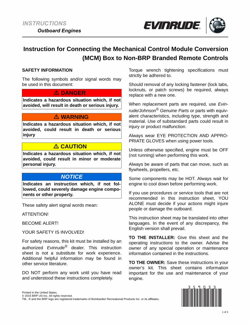
Mercury Remote Controls: Assemble the shiftand throttle control cables to the MCM trunnionpocket at the #3 “end point” of the cable anchor.
Shift the remote control to the FORWARD geardetent.
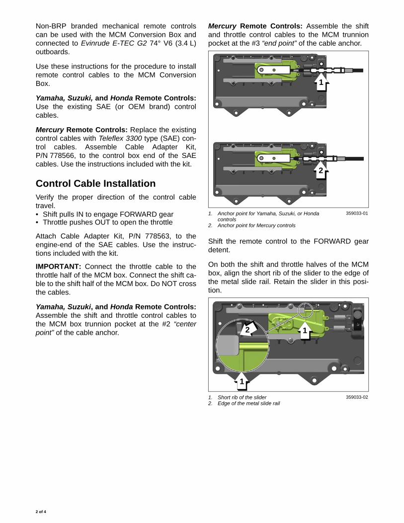
On both the shift and throttle halves of the MCMbox, align the short rib of the slider to the edge ofthe metal slide rail. Retain the slider in this posi-tion.
1. Anchor point for Yamaha, Suzuki, or Honda controls
2. Anchor point for Mercury controls
359033-01
1. Short rib of the slider2. Edge of the metal slide rail
359033-02
1
2
12
1
2 of 4
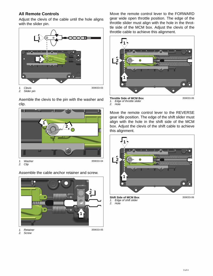
All Remote ControlsAdjust the clevis of the cable until the hole alignswith the slider pin.
Asemble the clevis to the pin with the washer andclip.
Assemble the cable anchor retainer and screw.
Move the remote control lever to the FORWARDgear wide open throttle position. The edge of thethrottle slider must align with the hole in the throt-tle side of the MCM box. Adjust the clevis of thethrottle cable to achieve this alignment.
Move the remote control lever to the REVERSEgear idle position. The edge of the shift slider mustalign with the hole in the shift side of the MCMbox. Adjust the clevis of the shift cable to achievethis alignment.
1. Clevis2. Slider pin
359033-03
1. Washer2. Clip
359033-04
1. Retainer2. Screw
359033-05
1
2
21
1
2
Throttle Side of MCM Box1. Edge of throttle slider2. Hole
359033-06
Shift Side of MCM Box1. Edge of shift slider2. Hole
359033-06
1
1
2
1
1
2
3 of 4

Move the remote control lever to the REVERSEwide open throttle position. The edge of the throt-tle slider will align to the position shown.
NOTE: It is normal for reverse throttle to have areduced stroke length.
Move the remote control lever to the NEUTRALidle position.
Use the instructions included with the MCM kit toassemble the halves of the box and complete theinstallation into the vessel.
Throttle Side of MCM Box1. Edge of throttle slider
359033-07
1
1
4 of 4
Top Related