


Languages
Pages
Legal

Q U I C K I N S T A L L G U I D E
Installing the Enphase Envoy-S MeteredTo install the Enphase Envoy-S Metered™ gateway with integrated meter, read and follow all warnings and instructions in this Guide and in the Enphase Envoy-S Installation and Operation Manual at: enphase.com/support. Safety warnings are listed on the back of this guide.
PREPARATIONA ) Download the latest version of the Enphase Installer
Toolkit mobile app and open it to log in to your Enlighten account. With this app, you can connect to the Envoy-S to track system installation progress. To download, go to enphase.com/toolkit or scan the QR code at right.
B ) Check the box for the following items:• Enphase Envoy-S Metered gateway• Two split-core current transformers (CTs) for production and
consumption metering• Length of DIN rail for mounting• Ferrite bead to attach to your Ethernet Cable, if used• Quick Install Guide (this document) and the Installation Supple-
ment (for multi-phase installations)
C ) Check that there is enough space in the switchboard to install CTs. Do not install the CTs in a panel where they exceed 75% of the wiring space of any cross-sectional area within the panel.
D ) You must install the Envoy-S Metered in an IP54-rated, or better enclosure with conduit attachment when installing outdoors. Do not drill holes on the top of the enclosure or anywhere that allows moisture ingress. Use an appropriately rated enclosure if hard wiring the Envoy-S indoors.
E ) If you are installing the Envoy-S in a multi-phase application, follow the instructions in the Installation Supplement.
F ) Decide how to connect the Envoy-S to the Internet: Wi-Fi, an Enphase Mobile Connect modem, or Ethernet.
G ) Make sure you have the following optional items, if needed:• Enphase Mobile Connect modem (order CELLMODEM-02)• Ethernet over power line communication (PLC) bridge with Ether-
net cables [order EPLC-02 (EU), EPLC-03 (UK) or EPLC-04 (AU)]• Ethernet cable [802.3, Cat5E or Cat6, unshielded twisted pair
(UTP)]. Do not use shielded twisted pair (STP) cable.H ) Install the PV modules and microinverters as directed by the installa-
tion manuals.I ) Create a paper installation map to record microinverter serial num-
bers and positions in the array. You will scan this map later using Installer Toolkit and your mobile device.• As you did with the microinverters, peel the removable label from
the bottom of the Envoy-S and affix it to the paper installation map.• Always keep a copy of the installation map for your records and to
upload to Enlighten later.
NOTE: If needed, you can find an installation map at the back of any Enphase Microinverter Quick Install Guide.
INSTALLATION
Choose a location for the Envoy-SA ) Install the Envoy-S Metered in an IP54-rated, or better enclosure
with conduit attachment when installing outdoors. Use an appropri-ately rated enclosure if hard wiring the Envoy-S indoors.
NOTE: Metallic enclosures may impair Wi-Fi signal strength.B ) Mount the Envoy-S horizontally using the included DIN rail.
1
(Model ENV-S-WM1-230)
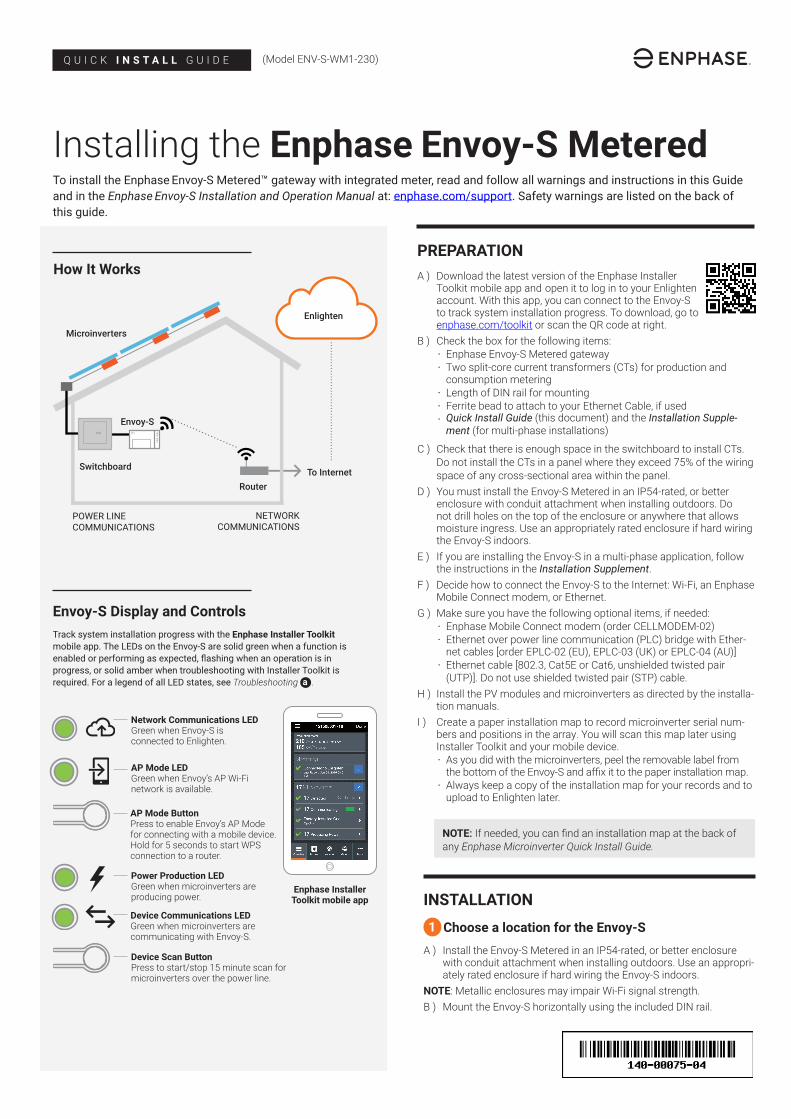
Envoy-S Display and Controls
Network Communications LED Green when Envoy-S is connected to Enlighten.
AP Mode LEDGreen when Envoy’s AP Wi-Fi network is available.
AP Mode ButtonPress to enable Envoy’s AP Mode for connecting with a mobile device. Hold for 5 seconds to start WPS connection to a router.
Power Production LED Green when microinverters are producing power.
Device Communications LEDGreen when microinverters are communicating with Envoy-S.
Device Scan ButtonPress to start/stop 15 minute scan for microinverters over the power line.
Track system installation progress with the Enphase Installer Toolkit mobile app. The LEDs on the Envoy-S are solid green when a function is enabled or performing as expected, flashing when an operation is in progress, or solid amber when troubleshooting with Installer Toolkit is required. For a legend of all LED states, see Troubleshooting a .
Enphase Installer Toolkit mobile app
How It Works
POWER LINE COMMUNICATIONS
NETWORK COMMUNICATIONS
Microinverters
Envoy-S
Switchboard
Router
Enlighten
To Internet
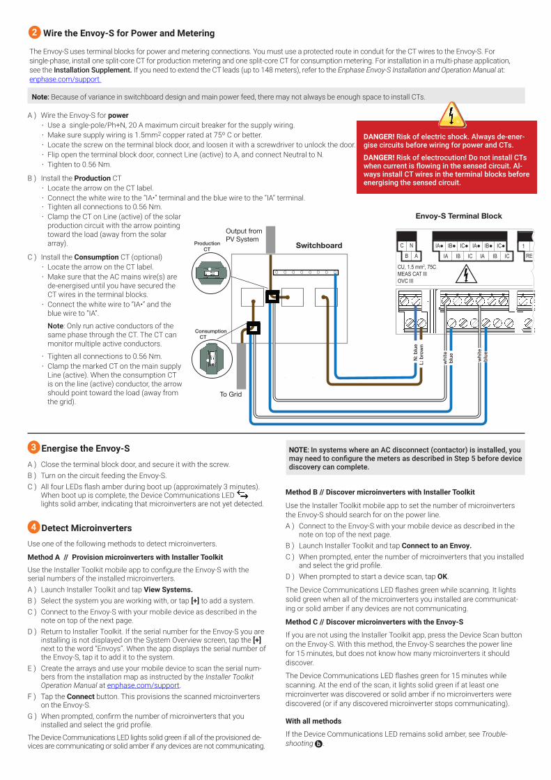
A ) Wire the Envoy-S for power• Use a single-pole/Ph+N, 20 A maximum circuit breaker for the supply wiring.• Make sure supply wiring is 1.5mm2 copper rated at 75º C or better.• Locate the screw on the terminal block door, and loosen it with a screwdriver to unlock the door.• Flip open the terminal block door, connect Line (active) to A, and connect Neutral to N. • Tighten to 0.56 Nm.
B ) Install the Production CT• Locate the arrow on the CT label.• Connect the white wire to the “IA•” terminal and the blue wire to the “IA” terminal. • Tighten all connections to 0.56 Nm.• Clamp the CT on Line (active) of the solar
production circuit with the arrow pointing toward the load (away from the solar array).
C ) Install the Consumption CT (optional)• Locate the arrow on the CT label.• Make sure that the AC mains wire(s) are
de-energised until you have secured the CT wires in the terminal blocks.
• Connect the white wire to “IA•” and the blue wire to “IA”.
Note: Only run active conductors of the same phase through the CT. The CT can monitor multiple active conductors.
• Tighten all connections to 0.56 Nm.• Clamp the marked CT on the main supply
Line (active). When the consumption CT is on the line (active) conductor, the arrow should point toward the load (away from the grid).
Wire the Envoy-S for Power and Metering
The Envoy-S uses terminal blocks for power and metering connections. You must use a protected route in conduit for the CT wires to the Envoy-S. For single-phase, install one split-core CT for production metering and one split-core CT for consumption metering. For installation in a multi-phase application, see the Installation Supplement. If you need to extend the CT leads (up to 148 meters), refer to the Enphase Envoy-S Installation and Operation Manual at: enphase.com/support.
Energise the Envoy-SA ) Close the terminal block door, and secure it with the screw.B ) Turn on the circuit feeding the Envoy-S.C ) All four LEDs flash amber during boot up (approximately 3 minutes).
When boot up is complete, the Device Communications LED lights solid amber, indicating that microinverters are not yet detected.
Detect MicroinvertersUse one of the following methods to detect microinverters.
Method A // Provision microinverters with Installer Toolkit
Use the Installer Toolkit mobile app to configure the Envoy-S with the serial numbers of the installed microinverters.A ) Launch Installer Toolkit and tap View Systems.B ) Select the system you are working with, or tap [+] to add a system.C ) Connect to the Envoy-S with your mobile device as described in the
note on top of the next page.D ) Return to Installer Toolkit. If the serial number for the Envoy-S you are
installing is not displayed on the System Overview screen, tap the [+] next to the word “Envoys”. When the app displays the serial number of the Envoy-S, tap it to add it to the system.
E ) Create the arrays and use your mobile device to scan the serial num-bers from the installation map as instructed by the Installer Toolkit Operation Manual at enphase.com/support.
F ) Tap the Connect button. This provisions the scanned microinverters on the Envoy-S.
G ) When prompted, confirm the number of microinverters that you installed and select the grid profile.
The Device Communications LED lights solid green if all of the provisioned de-vices are communicating or solid amber if any devices are not communicating.
Method B // Discover microinverters with Installer Toolkit
Use the Installer Toolkit mobile app to set the number of microinverters the Envoy-S should search for on the power line.A ) Connect to the Envoy-S with your mobile device as described in the
note on top of the next page.B ) Launch Installer Toolkit and tap Connect to an Envoy.C ) When prompted, enter the number of microinverters that you installed
and select the grid profile.D ) When prompted to start a device scan, tap OK.
The Device Communications LED flashes green while scanning. It lights solid green when all of the microinverters you installed are communicat-ing or solid amber if any devices are not communicating.
Method C // Discover microinverters with the Envoy-S
If you are not using the Installer Toolkit app, press the Device Scan button on the Envoy-S. With this method, the Envoy-S searches the power line for 15 minutes, but does not know how many microinverters it should discover.
The Device Communications LED flashes green for 15 minutes while scanning. At the end of the scan, it lights solid green if at least one microinverter was discovered or solid amber if no microinverters were discovered (or if any discovered microinverter stops communicating).
With all methods
If the Device Communications LED remains solid amber, see Trouble-shooting b .
2
Note: Because of variance in switchboard design and main power feed, there may not always be enough space to install CTs.
3
4
Envoy-S Terminal Block
Switchboard
Output from PV SystemProduction
CT
ConsumptionCT
L: b
row
n
blueN: b
lue
blue whi
te
whi
te
CU, 1.5 mm2, 75CMEAS CAT IIIOVC III
C
B
N
A
IA●
IA
IB●
IB
IC●
IC
IA●
IA
IB●
IB
IC●
IC1 2
REF
Production Consumption Digital Input
To Grid
DANGER! Risk of electric shock. Always de-ener-gise circuits before wiring for power and CTs.
DANGER! Risk of electrocution! Do not install CTs when current is flowing in the sensed circuit. Al-ways install CT wires in the terminal blocks before energising the sensed circuit.
NOTE: In systems where an AC disconnect (contactor) is installed, you may need to configure the meters as described in Step 5 before device discovery can complete.
WARNING: Do not remove power from the Envoy-S if the LEDs are flashing green. This indicates that a software upgrade is in progress.
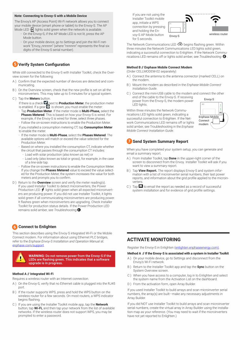
If you are not using the Installer Toolkit mobile app, initiate a WPS connection by pressing and holding the En-voy-S AP Mode button for 5 seconds.
The Network Communications LED begins flashing green. Within three minutes the Network Communications LED lights solid green, indicating a successful connection to Enlighten. If the Network Commu-nications LED remains off or lights solid amber, see Troubleshooting d .
Method B // Enphase Mobile Connect Modem (Order CELLMODEM-02 separately)A ) Connect the antenna to the antenna connector (marked CELL) on
the modem.B ) Mount the modem as described in the Enphase Mobile Connect
Installation Guide.C ) Connect the mini-USB cable to the modem and connect the other
end of the cable to the Envoy-S. If receiving power from the Envoy-S, the modem power LED lights.
Within three minutes the Network Commu-nications LED lights solid green, indicating a successful connection to Enlighten. If the Net-work Communications LED remains off or lights solid amber, see Troubleshooting in the Enphase Mobile Connect Installation Guide.
Send System Summary Report
When you have completed your system setup, you can generate and email a summary report.A ) From Installer Toolkit, tap Done in the upper-right corner of the
screen to disconnect from the Envoy. Installer Toolkit will ask if you want to view a summary report.
B ) Tap View Report. The report displays Envoy-S and system infor-mation with a list of microinverter serial numbers, their last power reports, and information about the grid profile applied to the microin-verters.
C ) Tap to email the report as needed as a record of successful system installation and for evidence of grid profile settings.
Register the Envoy-S in Enlighten (enlighten.enphaseenergy.com).
Method A // If the Envoy-S is associated with a system in Installer ToolkitA ) On your mobile device, go to Settings and disconnect from the
Envoy’s Wi-Fi network.B ) Return to the Installer Toolkit app and tap the Sync button on the
System Overview screen.C ) When you have access to a computer, log in to Enlighten and select
the system name from the Activation List on the dashboard.D ) From the activation form, open Array Builder.
If you used Installer Toolkit to build arrays and scan microinverter serial numbers, the array(s) are built —make any necessary adjustments in Array Builder.
If you did NOT use Installer Toolkit to build arrays and scan microinverter serial numbers, create the virtual array in Array Builder using the installa-tion map as your reference. (You may need to wait if the microinverters have not yet reported to Enlighten.)
Note: Connecting to Envoy-S with a Mobile Device
The Envoy’s AP (Access Point) Wi-Fi network allows you to connect your mobile device (smart phone or tablet) to the Envoy-S. The AP Mode LED lights solid green when the network is available.
• On the Envoy-S, if the AP Mode LED is not lit, press the AP Mode button.
• On your mobile device, go to Settings and join the Wi-Fi net-work “Envoy_nnnnnn” (where “nnnnnn” represents the final six digits of the Envoy-S serial number).
Verify System Configuration
While still connected to the Envoy-S with Installer Toolkit, check the Over-view screen for the following: A ) Confirm that the expected number of devices are detected and com-
municating.B ) On the Overview screen, check that the new profile is set on all the
microinverters. This may take up to 5 minutes for a typical system.C ) Tap the Meters button.
If there is a check next to Production Meter, the production meter is enabled. If a gear is shown, you must enable the meter:• Tap Production Meter. If the meter mode is Multi-Phase, select the
Phases Metered. This is based on how your Envoy-S is wired. For example, if the Envoy-S is wired for three, select three phases.
• Follow the on-screen instructions to enable the Production Meter.If you installed a consumption metering CT, tap Consumption Meter to enable the meter.• If the meter mode is Multi-Phase, select the Phases Metered. The
available options will match or exceed the value selected for the Production Meter.
• Based on where you installed the consumption CT, indicate whether the circuit that passes through the consumption CT includes:- Load with solar production (also known as net) or - Load only (also known as total or gross), for example, in the case
of a line-side tap.• Follow the on-screen instructions to enable the Consumption Meter.
If you change the Phases Metered value to exceed the value select-ed for the Production Meter, the system increases the value for both meters and prompts you to confirm.
D ) Return to the Overview screen and verify the meter reading(s). If you used Installer Toolkit to detect microinverters, the Power Production LED lights solid green when all expected microinvert-ers are producing power. If you did not use Installer Toolkit, it lights solid green if all communicating microinverters are producing power. It flashes green when microinverters are upgrading. Check Installer Toolkit for production status details. If the Power Production LED remains solid amber, see Troubleshooting c .
Connect to EnlightenThis section describes using the Envoy-S integrated Wi-Fi or the Mobile Connect modem. For information about using Ethernet PLC bridges, refer to the Enphase Envoy-S Installation and Operation Manual at: enphase.com/support.
Method A // Integrated Wi-Fi Requires a wireless router with an Internet connection.A ) On the Envoy-S, verify that no Ethernet cable is plugged into the RJ45
port. B ) If the router supports WPS, press and hold the WPS button on the
wireless router for a few seconds. On most routers, a WPS indicator begins flashing.
C ) If you are using the Installer Toolkit mobile app, tap the Network button, tap Wi-Fi, and then tap your network from the list of available networks. If the wireless router does not support WPS, you may be prompted to enter a password.
ACTIVATE MONITORING
7
6
5
wireless routerEnvoy-S
Enphase Mobile Connectmodem
Envoy-S
Method B // If the Envoy-S is NOT associated with a system in Installer ToolkitA ) Log into Enlighten and click Add a New System from the dashboard.B ) Enter the System, Installer, Owner, and Location information.C ) Enter the Envoy-S serial number.D ) Click Save to submit the form.E ) After the microinverters have reported to Enlighten, open Array
Builder from the activation form, and create the virtual array, using the installation map as your reference.
Enphase Customer Support: http://enphase.com/global/support-request/
SAFETYSafety and Advisory Symbols
DANGER: This indicates a hazardous situation, which if not avoided, will result in death or serious injury.
⚠ WARNING: This indicates a situation where failure to follow instruc-tions may be a safety hazard or cause equipment malfunction. Use extreme caution and follow instructions carefully.
✓ NOTE: This indicates information particularly important for optimal system operation. Follow instructions carefully.
Safety InstructionsDANGER: Risk of electric shock. Risk of fire. Do not attempt to repair the Envoy-S; it contains no user-serviceable parts. Tampering with or opening the Envoy-S will void the warranty. Warranty void if cover removed. If the Envoy-S fails, contact Enphase Customer Support for assistance (http://enphase.com/global/support-request/).
DANGER: Risk of electrocution! Do not install CTs when current flow-ing in the sensed circuit. Always install CT wires in the terminal blocks before energising the sensed circuit.
DANGER: Risk of electric shock. Do not use Enphase equipment in a manner not specified by the manufacturer. Doing so may cause death or injury to persons, or damage to equipment.
DANGER: Risk of electric shock. Be aware that installation of this equipment includes risk of electric shock. If you wire the Envoy-S at the sub-board, always de-energise the sub-board before beginning.
DANGER: Risk of electric shock. Risk of fire. Only qualified personnel should troubleshoot, install, or replace the Envoy-S.
DANGER: Risk of electric shock. Risk of fire. Do not wire unused termi-nals or terminal blocks on the Envoy-S.
⚠ WARNING: Before installing or using the Envoy-S, read all instructions and cautionary markings in the technical description and on the Envoy-S.
⚠ WARNING: Risk of equipment damage. If installing the Envoy-S in an enclosure, choose area for installation where ambient temperature does not exceed 46º C.
✓ NOTE: Do not install the CTs in a panel where they exceed 75% of the wiring space of any cross-sectional area within the panel, or refer to local standards for guidance.
✓ NOTE: Perform all electrical installations in accordance with all nation-al and local electrical codes.
✓ NOTE: To ensure optimal reliability and to meet warranty require-ments, the Enphase Envoy-S must be installed according to the instructions in this guide.
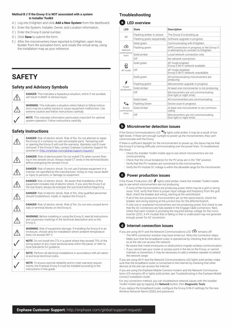
Troubleshooting
a LED overviewLED State Description
AllFlashing amber in unison The Envoy-S is booting upFlashing green sequentially Software upgrade in progress
Networkcommunica-
tions
Solid green Communicating with EnlightenFlashing green WPS connection in progress or the Envoy-S
is attempting to connect to EnlightenSolid amber Local network connection onlyOff No network connection
AP mode
Solid green AP mode enabled: Envoy-S Wi-Fi network available
Off AP mode disabled:Envoy-S Wi-Fi network unavailable
Power production
Solid green All communicating microinverters are producing
Flashing green Microinverter upgrade in progressSolid Amber At least one microinverter is not producingOff Microinverters are not communicating
(low light or night time)
Devicecommunica-
tions
Solid Green All microinverters are communicatingFlashing Green Device scan in progressSolid Amber At least one microinverter is not communi-
catingOff Microinverters are not communicating
(low light or night time)
b Microinverter detection issuesIf the Device Communications LED lights solid amber, it may be a result of low light levels. If there isn’t enough sunlight to power up the microinverters, they can’t communicate with the Envoy.If there is sufficient daylight for the microinverters to power up, the issue may be that the Envoy-S is having difficulty communicating over the power lines. To troubleshoot this issue:
• Check the Installer Toolkit mobile app to see which microinverters are not communicating.
• Check that the circuit breaker(s) for the PV array are in the “ON” position. • Verify that the PV modules are connected to the microinverters. • Verify the PV module DC voltage is within the allowable range for the microinverter.
c Power production issuesIf the Power Production LED lights solid amber, check the Installer Toolkit mobile app to see which microinverters are not producing:
• If none of the microinverters are producing power, there may be a grid or wiring issue. First, verify that there is proper input voltage and frequency from the grid. Next, check the breaker and wiring, starting at the switchboard.
• If all of the non-productive microinverters are on the same branch, check the breaker and wiring starting at the junction box for the affected branch.
• If only one or scattered microinverters are not producing power, first check to see that the AC connectors are fully seated in the Engage Cable connectors. Next, check that each module is providing the required startup voltage for the micro-inverter (22V). A PV module that is failing or that is undersized may not generate enough power for AC conversion.
d Internet connection issuesIf you are using Wi-Fi and the Network Communications LED remains off:
• The WPS connection window may have timed out. Retry the connection steps.• Make sure that the broadband router is operational by checking that other devic-
es at the site can access the network. • Be aware that metal enclosures or obstructions impede wireless communication. • If you cannot see your router or access point in the list on the Envoy, or cannot
maintain a connection, it may be necessary to add a wireless repeater to extend the network range.
If you are using Wi-Fi and the Network Communications LED lights solid amber, make sure that the broadband router is connected to the Internet by checking that other devices at the site can access the Internet.If you are using the Enphase Mobile Connect modem and the Network Communica-tions LED remains off or lights solid amber, see Troubleshooting in the Enphase Mobile Connect Installation Guide.For any connection method, you can troubleshoot network issues with the Installer Toolkit mobile app by tapping the Network button, then Diagnostic Tools.If you replace the broadband router, configure the Envoy-S Wi-Fi settings for the new Wireless Network Name (SSID) and password.
Top Related