


Languages
Pages
Legal


Installation GuideSavi Fixed Reader SR-650-101Version 1.0

Published May 2008
Part number 805-04399-001 Rev C
Documentation for Savi Fixed Reader SR-650-101Copyright © 2008 Savi Technology, Inc. All rights reserved. Unpublished rights reserved under the Copyright Laws of the United States.
EchoPoint, Savi, Savi SensorTag, Savi SmartChain, Savi SmartStart, Savi Technology, SaviTag, SmartChain, the EchoPoint Logo, the Savi Logo, the UDAP Logo, and UDAP are trademarks or registered trademarks of Savi Technology, Inc. in the United States and other countries.
Information in this manual is subject to change without notice and does not represent a commitment from the vendor. The software and/or databases described in this document are furnished under a license agreement or nondisclosure agreement. The software and/or databases may be used or copied only in accordance with the terms of the agreement. It is against the law to copy the software on any medium except as specifically allowed in the license or nondisclosure agreement.
THIS DOCUMENTATION CONTAINS CONFIDENTIAL INFORMATION AND TRADE SECRETS OF SAVI TECHNOLOGY, INC. USE, DISCLOSURE OR REPRODUCTION IS PROHIBITED WITHOUT THE PRIOR EXPRESS WRITTEN PERMISSION OF SAVI TECHNOLOGY, INC.
U.S. GOVERNMENT RIGHTS
Use, duplication or disclosure by the U.S. government is subject to restrictions set forth in the Savi Technology, Inc. license agreement and as provided in DFARS 227.7202-1(a) and 227.7202-3(a) (1995), DFARS 252.227-7013(c)(1)(ii) (OCT 1988), FAR 12.212(a) (1995), FAR 52.227-19 or FAR 52.227-14 (ALT III), as applicable. Savi Technology, Inc.
Other product names mentioned in this guide may be trademarks or registered trademarks of their respective owners and are hereby acknowledged.
Savi Technology A Lockheed Martin Company 351 East Evelyn Avenue Mountain View, CA 94041-1530 Phone: 1-650-316-4700 Facsimile: 1-650-316-4750 www.savi.com

FCC Registration Required for Operation under Rule 15.240 Radio transmissions from the SR-650-101 are governed in the US by FCC Part 15 rules, and in Canada by corresponding Industry Canada regulation RSS-210 . Still other regulations apply in Europe and other countries. The SR-650-101 is shipped with the default mode of operation corresponding to FCC 15.231. All prior Savi equipment complies with 15.231. Equipment operating under this rule does not require FCC Registration. FCC Rule 15.240 offers some advantages in thru-put and flexibility for applications involving containerized cargo. The SR-650-101 can be configured for operation under this rule only by a qualified technician downloading factory-supplied configuration files. There are restrictions in the geographical locations where such equipment may be deployed so as to maintain a 40 km separation from five long-range radar sites in the US and Alaska. The FCC requires notification of the locations where 15.240 operating equipment is to be installed. Savi Technology, Inc. notifies the FCC of the initial shipping destination. However, it is the responsibility of the end user to mail a notification of installation to the FCC as described in the form provided below upon initial installation. It is also required that the user mail a new notification in the event the equipment is re-located. The form is to be mailed to:
Experimental Licensing Branch Office of Engineering & Technology
Federal Communications Commission 445 12th Street, SW
Washington, DC 20554 ATTN: RFID Registration
Selected text from FCC Rule 15.240 Operation in the band 433.5 – 434.5 MHz
(a) “Operation under this section is restricted to devices that use radio frequency energy to identify the contents of commercial shipping containers. Operations must be limited to commercial and industrial areas such as ports, rail terminals and warehouses.”
(e) “To prevent interference to Federal Government radar systems, operation under the
provisions of this section is not permitted within 40 kilometers of the following locations:”
DoD Radar Site Latitude Longitude Beale Air Force Base 39o08’10”N 121o21’04”W Cape Cod Air Force Station 41o45’07”N 070o32’17”W Clear Air Force Station 64o55’16”N 143o05’02”W Cavalier Air Force Station 48o43’12” 097o54’00”W Eglin Air Force Base 30o43’12” 086o12’36”W

FCC RFID REGISTRATION FORM FOR FCC RULE 15.240
To:
Experimental Licensing Branch, OET Federal Communications Commission 445 12th Street, SW Washington, DC 20554 ATTN: RFID Registration
Subject: Registration for Savi Technology, Inc. Model SR-650-101 RFID Fixed Interrogator The following information concerning the end user and installation location is hereby submitted as required by FCC Rule 15.240: End User Company Name: _________________________________ Individual to Contact: _________________________________ Mailing Address of Contact: _________________________________
_________________________________ _________________________________
Street Address of Contact Office: _______________________________ _________________________________ _________________________________
Contact Telephone Number: _________________________________ Contact E-Mail Address: _________________________________ Street Address of Equipment Installation: ____________________________
____________________________ ____________________________
Latitude: _______________________Longitude: ______________________ FCC ID of Equipment: KL7-650R-V2 _____________________________ _________________ Contact Signature Date

Savi Fixed Reader SR-650 3
Contents1 Introduction
Features . . . . . . . . . . . . . . . . . . . . . . . . . . . . . . . . . . . . . . . . . . . . . 6
Reader Description . . . . . . . . . . . . . . . . . . . . . . . . . . . . . . . . . . . . . 6
Network Communication . . . . . . . . . . . . . . . . . . . . . . . . . . . . . . 6
Tag Communication . . . . . . . . . . . . . . . . . . . . . . . . . . . . . . . . . . 7
Specifications . . . . . . . . . . . . . . . . . . . . . . . . . . . . . . . . . . . . . . . 8
Models and Options . . . . . . . . . . . . . . . . . . . . . . . . . . . . . . . . . 11
Contacting Savi Global Support Services . . . . . . . . . . . . . . . . . . 13
2 Designating Locations and Connecting Cables
Planning a Site . . . . . . . . . . . . . . . . . . . . . . . . . . . . . . . . . . . . . . . 15
Connecting Power Cables to the Savi Fixed Reader . . . . . . . . . . 15
Connecting the Network Cables . . . . . . . . . . . . . . . . . . . . . . . . . 18
SaviNet Connection (RS-485) . . . . . . . . . . . . . . . . . . . . . . . . . 18
Ethernet Connection . . . . . . . . . . . . . . . . . . . . . . . . . . . . . . . . . 21
Applying Power to the Savi Fixed Reader . . . . . . . . . . . . . . . . . . 25
3 Managing the Reader Network
Identifying the Savi Fixed Reader in SmartChain Site Manager . 28
Adding and Configuring the Reader in SmartChain Site Manager . . . . . . . . . . . . . . . . . . . . . . . . . . . . . . . . . . . . . . . . . . . . 29
Discovering a Reader Using an Ethernet Connection . . . . . . . 29
Discovering a Reader Using a SaviNet Connection (RS-485) . 31

4 Savi Fixed Reader SR-650
Adding a Reader Manually Using an Ethernet Connection . . . 31
Setting the Host IP and Synchronizing Time . . . . . . . . . . . . . . 32
Configuring the Reader with Savi Retriever Using a SaviNet Connection (RS-485) . . . . . . . . . . . . . . . . . . . . . . . . . . . . . . . . . . . 33
Verifying Reader Communication . . . . . . . . . . . . . . . . . . . . . . . . . 34
4 Installing the Savi Fixed Reader
Positioning the Savi Fixed Reader . . . . . . . . . . . . . . . . . . . . . . . . 35
Mounting the Savi Fixed Reader . . . . . . . . . . . . . . . . . . . . . . . . . . 37
5 Reader Sustainment and Maintenance
Repair and Maintenance . . . . . . . . . . . . . . . . . . . . . . . . . . . . . . . . 39
Troubleshooting . . . . . . . . . . . . . . . . . . . . . . . . . . . . . . . . . . . . . . . 40
A Using Telnet to Connect to a Savi Fixed Reader
Setting Up the Savi Fixed Reader . . . . . . . . . . . . . . . . . . . . . . . . . 41
Configuring Your PC’s IP Address . . . . . . . . . . . . . . . . . . . . . . 41
Pinging the Savi Fixed Reader . . . . . . . . . . . . . . . . . . . . . . . . . 46
Configuring the Savi Fixed Reader . . . . . . . . . . . . . . . . . . . . . . 47
B Installing and Removing Heat Shrink Tubing
Installing Heat Shrink Tubing . . . . . . . . . . . . . . . . . . . . . . . . . . . . 56
Removing Heat Shrink Tubing . . . . . . . . . . . . . . . . . . . . . . . . . . . 56

C H A P T E R 1
Savi Fixed Reader SR-650-101 Installation Guide 5
Introduction 1You can use the Savi® Fixed Reader SR-650-101 to scan, detect, and collect tag information. The SR-650-101 reader is designed to communicate with all models of SaviTags, and forward the collected data to the Savi SmartChain® Site Manager or SmartChain® Client Tools host platforms. You can network multiple readers to cover large facilities.
Working with Savi Signposts, SR-650-101 readers provide a complete RFID solution for real-time, end-to-end visibility of goods and critical assets moving through the supply chain.
Figure 1-1 Savi Fixed Reader SR-650-101

C H A P T E R 1 Introduction
6 Savi Fixed Reader SR-650-101 Installation Guide
Features◆ Long-range, omnidirectional communication enables effective
monitoring of thousands of tagged items over a 328-foot (100 meters) radius—ideal for yards, terminals, and warehouses.
◆ Ethernet connectivity supports wired and wireless installations, allowing multiple readers to be easily networked together.
◆ Universal Data Appliance Protocol™ (UDAP™) provides interoperability with other data collection devices, including bar code scanners and other RFID readers.
◆ SmartChain Site Manager provides a seamless interface to the Savi SmartChain platform and applications.
◆ Rugged, weatherproof packaging permits indoor and outdoor usage.
Reader DescriptionThe Savi Fixed Reader SR-650-101 has an omnidirectional read pattern with an adjustable range of up to 300 feet (91.44 meters), and can be networked to provide cellular coverage of a nearly unlimited area. Its power source can be 92 to 250 VAC or 12 to 24 VDC. A portable tripod mount, a solar power unit, or a cable for powering the reader from a vehicle are all available for use with the SR-650-101 reader.
The Savi Fixed Reader SR-650-101 operates at 433.92 MHz.
Network CommunicationThe Savi Fixed Reader SR-650-101 supports two types of network protocols: SaviNet (RS-485) and Ethernet via RJ-45 connector; 10Base-T (TCP/IP).
The Savi Fixed Reader SR-650-101 is compatible with SaviNet installations using the RS-485 protocol, and can be used in a mixed configuration that includes both older Savi Fixed Interrogator 2.0 and SaviReader 410 models.

Reader Description
Savi Fixed Reader SR-650-101 Installation Guide 7
Tag CommunicationThe Savi Fixed Reader SR-650-101 can transmit control commands and data over a UHF link to SaviTags. In return, the SaviTags transmit status information, recognition codes, and data over the UHF link to the reader, depending on the commands the tag received.
The Savi Fixed Reader SR-650-101 supports three UHF air interface protocols for SaviTags, which are formats through which Savi products transmit data:
◆ Batch Collection System® (BCS)◆ Extended BCS (EBCS)◆ EchoPoint
BCS and EBCS air protocols support 20-bit tag identification; EchoPoint air protocol supports 32-bit tag identification.
The following table lists the SaviTag models that are compatible with the Savi Fixed Reader SR-650-101.
Tag Model Number Air Interface Protocols Support
SealTag II BCS Yes
SealTag III BCS Yes
ST-410-108 EBCS Yes
ST-410-113 No
ST-410-115 No
ST-410-118 EBCS Yes
ST-412U1 EBCS Yes
ST-602 EchoPoint Yes
ST-604 EchoPoint Yes
ST-645 EchoPoint Yes
ST-654 BCS, EBCS, and EchoPoint Yes
ST-655 BCS, EBCS, and EchoPoint Yes

C H A P T E R 1 Introduction
8 Savi Fixed Reader SR-650-101 Installation Guide
SpecificationsThe Savi Fixed Reader SR-650-101 can be mounted in permanent or semipermanent sites, as well as in a mobile vehicle. SR-650-101 readers are designed for indoor or outdoor use.
Specification Description
Physical characteristics Length: 12 inches (30.48 cm) in diameter
Height: 7 inches (17.78 cm)
Weight: 4.2 pounds (1.91 kg)
Case material: Polypropylene with UV inhibitors
Environment Temperature: -26°F to +140°F (-32°C to +60°C) operating; -40°F to +158°F (-40°C to +70°C) storage
Humidity: 100% condensing
RF receiver/transmitter UHF transceiver (uplink and downlink)
Frequency: 433.92 MHz
Range: Typical transmit range is approximately 328 feet (100 meters) line of sight from the reader to ST-65x and ST-41x tags. Typical transmit range is approximately 100 feet (30.48 meters) line of sight from the reader to ST-645 tags. Typical receive range is approximately 328 feet (100 meters) line of sight from all Savi tags
Modulation: FSK, deviation +/- 35KHz for receive, +/- 50KHz for transmit
Data rate: 27.8Kbps
Air protocol: BCS Commands, EBCS Commands (refer to Convergence RFID Air Protocol document)
EchoPoint Air Protocol 2.1 (refer to EchoPoint Air Protocol document)
✦ Two-way UHF commands
✦ Seal extension commands
Data coding: Manchester
Rx Signal Strength Indicator (RSSI): Supported
Architecture: Single UHF board with two channels
Maximum transmit power: 0.15mW

Reader Description
Savi Fixed Reader SR-650-101 Installation Guide 9
Network Interface:
✦ UDAP protocol over Ethernet 10Base-T
✦ Reader network supports wireless connectivity to host computer via external 802.11b communications
Memory On board non-volatile memory of 512 Kbytes for interim tag data
Tag compatibility All Savi RFID tags
Interfaces ✦ RS-232 interface via DB-9 female connector
Protocol: Savi Proprietary Serial Protocol
Data rate: 9600 Kbps
Flow control: CTS used for busy reader indication; half duplex communication
Data format: 8 data bits, none parity, 1 stop
RS-232 signals: TXD, RXD, CTS, RTS (connected, but not essential for operation)
✦ RS-485 2-wire differential via proprietary 4-pin differential
Protocol: SaviNet Proprietary Protocol
Data rate: 38.4 Kbps
Data format: 8 data bits, none parity, 1 stop
✦ Ethernet via RJ-45 connector; 10Base-T
Antenna Internal UHF: Orthogonal (omni) dual loop antenna
Shock and vibration MIL STD 810E Method 514.4, Category 10
Protection type Sealed to IP42, protection against objects larger than .04 inches (1mm) in diameter and protection from water falling as much as 15 degrees from vertical
Power AC Source: Universal Power Supply
92-250 VAC, 50/60 Hz, 300 mA max
DC Source: 12-24 VDC, 500 mA
Indicators: Standard seven-segment LED display
Specification Description

C H A P T E R 1 Introduction
10 Savi Fixed Reader SR-650-101 Installation Guide
Regulatory requirements Radiated emission (intentional):
U.S. emission standards as contained in FCC Part 15
Canada RSS210
European Community emission standards as contained in EN 300 220 (433 MHz)
Electromagnetic Immunity:
ESD compliance
Exposed to 8 kV air discharge or 4 kV contact discharge in accordance with EN 301 489-1
Radiated emission (unintentional):
U.S. emissions standards as contained in FCC Part 15
Medical Device EMC, IEC 60601-1-2
European Community emission standards as contained in EN 301 489-1
Safety approval:
U.S UL 1950
European EN 60950
Ordnance safety:
HERO pending; unit will meet requirements for 24” minimum safe separation distance
Accessories Savi Mounting Kit SRA-1001 (not included); Savi Heavy Duty Mounting Kit SRA-1024 (not included)
Specification Description
Reader Description
Savi Fixed Reader SR-650-101 Installation Guide 11
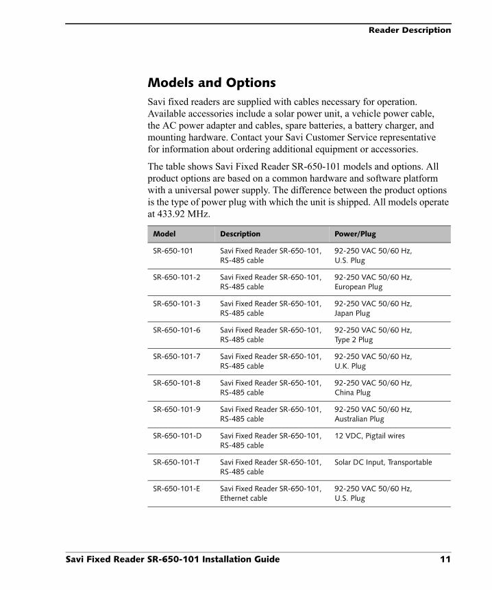
Models and OptionsSavi fixed readers are supplied with cables necessary for operation. Available accessories include a solar power unit, a vehicle power cable, the AC power adapter and cables, spare batteries, a battery charger, and mounting hardware. Contact your Savi Customer Service representative for information about ordering additional equipment or accessories.
The table shows Savi Fixed Reader SR-650-101 models and options. All product options are based on a common hardware and software platform with a universal power supply. The difference between the product options is the type of power plug with which the unit is shipped. All models operate at 433.92 MHz.
Model Description Power/Plug
SR-650-101 Savi Fixed Reader SR-650-101, RS-485 cable
92-250 VAC 50/60 Hz, U.S. Plug
SR-650-101-2 Savi Fixed Reader SR-650-101, RS-485 cable
92-250 VAC 50/60 Hz, European Plug
SR-650-101-3 Savi Fixed Reader SR-650-101, RS-485 cable
92-250 VAC 50/60 Hz, Japan Plug
SR-650-101-6 Savi Fixed Reader SR-650-101, RS-485 cable
92-250 VAC 50/60 Hz, Type 2 Plug
SR-650-101-7 Savi Fixed Reader SR-650-101, RS-485 cable
92-250 VAC 50/60 Hz, U.K. Plug
SR-650-101-8 Savi Fixed Reader SR-650-101, RS-485 cable
92-250 VAC 50/60 Hz, China Plug
SR-650-101-9 Savi Fixed Reader SR-650-101, RS-485 cable
92-250 VAC 50/60 Hz, Australian Plug
SR-650-101-D Savi Fixed Reader SR-650-101, RS-485 cable
12 VDC, Pigtail wires
SR-650-101-T Savi Fixed Reader SR-650-101, RS-485 cable
Solar DC Input, Transportable
SR-650-101-E Savi Fixed Reader SR-650-101, Ethernet cable
92-250 VAC 50/60 Hz, U.S. Plug

C H A P T E R 1 Introduction
12 Savi Fixed Reader SR-650-101 Installation Guide
SR-650-101-2E Savi Fixed Reader SR-650-101, Ethernet cable
92-250 VAC 50/60 Hz, European Plug
SR-650-101-3E Savi Fixed Reader SR-650-101, Ethernet cable
92-250 VAC 50/60 Hz, Japan Plug
SR-650-101-6E Savi Fixed Reader SR-650-101, Ethernet cable
92-250 VAC 50/60 Hz, Type 2 Plug
SR-650-101-7E Savi Fixed Reader SR-650-101, Ethernet cable
92-250 VAC 50/60 Hz, U.K. Plug
SR-650-101-8E Savi Fixed Reader SR-650-101, Ethernet cable
92-250 VAC 50/60 Hz, China Plug
SR-650-101-9E Savi Fixed Reader SR-650-101, Ethernet cable
92-250 VAC 50/60 Hz, Australian Plug
SR-650-101-DE Savi Fixed Reader SR-650-101, Ethernet cable
12 VDC, Pigtail wires
SR-650-101-TE Savi Fixed Reader SR-650-101, Ethernet cable
Solar DC Input, Transportable
Model Description Power/Plug
Contacting Savi Global Support Services
Savi Fixed Reader SR-650-101 Installation Guide 13
Contacting Savi Global Support ServicesIf you cannot find the information you need, contact Savi Global Support Services.
◆ Check www.savi.com/services/su.contact.shtml for contact information.◆ Send email to [email protected].◆ Call 1-888-994-7284 (North America only) or 650-316-4760 between
5 a.m. and 5 p.m. Pacific time.When you contact Savi Global Support Services by telephone or email, have the following information available:
◆ Contact information (company name, your name, email, and phone number)
◆ Problem description◆ Product type◆ Software version◆ Serial number or license information

C H A P T E R 1 Introduction
14 Savi Fixed Reader SR-650-101 Installation Guide

C H A P T E R 2
Savi Fixed Reader SR-650-101 Installation Guide 15
Designating Locations and Connecting Cables 2Before physically installing the Savi Fixed Reader SR-650-101, you must:
1. Consult a site plan to determine the reader’s installation location.
2. Connect power cables and network cables.
3. Supply power.
Planning a SiteTo plan a site you must conduct a site survey and plan the RFID network configuration. Once the site plan is in place, refer to it to determine where to install Savi fixed readers. Follow the directions in this manual to ensure proper installation of each Savi Fixed Reader SR-650-101.
Connecting Power Cables to the Savi Fixed ReaderNote: The Savi Fixed Reader SR-650-101 is rated for use in severe environments. For additional precautions, Savi recommends the use of heat shrink tubing (Savi part number 680-02423-001) for units subject to outdoor use.
Before you connect the Savi fixed reader’s power cable, be sure to check relevant configuration or wiring diagrams.
The power source can be 12 to 24 VDC or 92 to 250 VAC. The socket-outlet should be installed near the equipment and should be easily accessible. The Savi Fixed Reader SR-650-101 does not require adjustment or modification for different power sources. The appropriate power cable is supplied based on the requirements specified when the order was placed.

C H A P T E R 2 Designating Locations and Connecting Cables
16 Savi Fixed Reader SR-650-101 Installation Guide
You can also power the Savi Fixed Reader SR-650-101 from a Savi Solar Power Module or by vehicle power. A fixed-length, molded cable is supplied with the Solar Power Module. You can purchase the Vehicle Power Cable as an accessory.
To connect the power cable to the reader:
1. If you are installing the Savi Fixed Reader SR-650-101 in an outdoor location, slide heat shrink tubing onto the power cable before connecting the cable to the reader.
2. On the Savi fixed reader, plug the cable’s female connector into the power input socket. See Figure 2-1.
a. Turn the connector to align its notch on the side nearest the Savi fixed reader’s dome.
b. Firmly push the locking ring forward and rotate it clockwise to lock the connector.
Figure 2-1 Power connector
Insert the female connector of the power cable into the power input
Connector panel

Connecting Power Cables to the Savi Fixed Reader
Savi Fixed Reader SR-650-101 Installation Guide 17
Figure 2-2 Power cable
3. Ensure that the heat shrink tubing is protecting the power cable’s connector shell.
Position the heat shrink tubing so it is not completely against the reader’s connector panel and covering the entire connector shell but is .25 of an inch (6.35 mm) from the connector panel.
4. Apply heat to the heat shrink tubing to contract and bind the protective covering to the power cable and its connector shell.
For detailed instructions regarding application of the heat shrink tubing, follow the procedures in Appendix B.
Warning: To avoid static electricity shock, connect the network cables before applying power to the Savi fixed reader. Complete “Connecting the Network Cables” on page 18, and then proceed to “Applying Power to the Savi Fixed Reader” on page 25.
Connector shell
Plug to AC outlet

C H A P T E R 2 Designating Locations and Connecting Cables
18 Savi Fixed Reader SR-650-101 Installation Guide
Connecting the Network CablesBefore you connect the Savi fixed reader’s network cables, check relevant configuration or wiring diagrams.
Note: The Savi Fixed Reader SR-650-101 is rated for use in severe environments. For additional precautions, Savi recommends the use of heat shrink tubing (Savi part number 680-02423-001) for units subject to outdoor use.
You can connect the Savi fixed reader using two types of network protocols:
◆ SaviNet connection (RS-485)
◆ Ethernet via RJ-45 connector; 10Base-T
SaviNet Connection (RS-485)SaviNet requires an 8-foot (2.4 meters) network cable with an RS-485 to RS-232 converter on one end and an RS-485 connector on the other end to connect the Savi Fixed Reader SR-650-101 to the host computer.
With a SaviNet connection, you can:
◆ Connect one reader directly to a host computer
◆ Attach multiple readers in a daisy chain pattern
Connecting to the Host Computer
To directly connect the Savi Fixed Reader SR-650-101 to the host computer using the RS-485 port:
1. If you are installing the Savi fixed reader in an outdoor location, slide heat shrink tubing onto the network cable before connecting the cable to the reader.
For detailed instructions regarding application of the heat shrink tubing, follow the procedures in Appendix B.
2. Plug the SaviNet cable’s RS-485 female connector into the NETWORK IN port on the Savi fixed reader. Ensure that the notch is correctly aligned. See Figure 2-3.

Connecting the Network Cables
Savi Fixed Reader SR-650-101 Installation Guide 19
Note: The SaviNet cable with converter is provided with Savi software (such as Savi Retriever) since only one computer-connector cable is required per network. The SaviNet cable is also available separately (Savi part number 830-00911-001).
Figure 2-3 RS-485 ports
3. Push the locking ring forward firmly and rotate clockwise to lock the connector.
4. Connect the RS-232 converter end of the cable to the host computer’s RS-232 port.
Network In (RS-485 port)
Network Out(RS-485 port)

C H A P T E R 2 Designating Locations and Connecting Cables
20 Savi Fixed Reader SR-650-101 Installation Guide
Connecting Two or More Savi Fixed Readers
If you are connecting several Savi fixed readers in a daisy chain configuration, use a standard Savi-provided network cable to connect each reader, as shown in Figure 2-4.
Figure 2-4 Savi fixed readers in daisy chain configuration
To connect the multiple Savi fixed readers:
1. If you are installing the Savi fixed reader in an outdoor location, slide heat shrink tubing onto the network cables before connecting the cables to the reader.
For detailed instructions regarding application of the heat shrink tubing, follow the procedures in Appendix B.
2. Connect the first cable’s female connector (cable 1 in Figure 2-4) to the NETWORK IN port on the Savi fixed reader.
The other end of this cable connection connects to the host computer.
3. Using a second, unconnected cable (cable 2 in Figure 2-4), plug the cable’s male connector into the NETWORK OUT port on the Savi fixed reader.
4. Connect the female connector end of the second network cable (cable 2 in Figure 2-4) to the next reader’s NETWORK IN port.
To Host Computer
Network In
Network Out
Network In
Network In
Network In
Network Out
Network Out
Network Out
4
3
21

Connecting the Network Cables
Savi Fixed Reader SR-650-101 Installation Guide 21
5. Continue to link new readers as necessary (cables 3 and 4 in Figure 2-4). The final reader in the chain must be terminated with a matched resistive load (termination cable assembly) to prevent signal reflections in long cable runs.
Note: The termination cable assembly (Savi part number 830-04598-001) is included with the reader. If the distance between readers is greater than 100 feet (30.48 meters), additional network cables are available (Savi part number 830-00169-100). A cable adapter (Savi part number 625-00921-001) is included to connect two cables.
Ethernet ConnectionYou can connect the Savi Fixed Reader SR-650-101 directly to a network hub via the built-in Ethernet connection. The readers are the source of RFID tag read and service events. SmartChain Site Manager records, stores, and forwards these events to Savi SmartChain. SmartChain Site Manager also sends commands for reader management or control logic. The readers communicate with SmartChain Site Manager using UDAP.
SmartChain Site Manager and SmartChain are available separately from Savi Technology.

C H A P T E R 2 Designating Locations and Connecting Cables
22 Savi Fixed Reader SR-650-101 Installation Guide
To connect the Savi Fixed Reader SR-650-101 to an Ethernet hub:
1. Connect an RJ-45 connector to the Ethernet cable.
The other end of the Ethernet cable includes an RJ-45 connector with a protective connector shell.Figure 2-5 Ethernet cable and RJ-45 connector
RJ-45 connectorsRJ-45 connector with connector shell
Cable

Connecting the Network Cables
Savi Fixed Reader SR-650-101 Installation Guide 23
2. Cover the RJ-45 connector with an RJ-45 sleeve. Connect this end of the Ethernet cable to the Ethernet hub.Figure 2-6 RJ-45 connector and sleeve
3. Remove the protective cap from the Ethernet port on the Savi Fixed Reader SR-650-101.Figure 2-7 Ethernet port
Ethernet port

C H A P T E R 2 Designating Locations and Connecting Cables
24 Savi Fixed Reader SR-650-101 Installation Guide
4. Connect the RJ-45 connector with the connector shell into the Ethernet port.Figure 2-8 Connected Savi Fixed Reader SR-650-101
Note: Replace and tighten the protective cap when the Ethernet port is not used.

Applying Power to the Savi Fixed Reader
Savi Fixed Reader SR-650-101 Installation Guide 25
Applying Power to the Savi Fixed ReaderAfter connecting power and network cables, apply power to the reader by connecting the male connector end of the power cable to the appropriate power source, such as the Savi Solar Power Module or an AC outlet.
Figure 2-9 Savi Fixed Reader SR-650-101 LED display panel
To confirm that power is present in the reader:
1. Observe the indicators on the LED display panel. The power indicator should be illuminated whenever power is present.
a. During the initial power-on sequence, the Savi fixed reader concurrently displays a dot and a dash.
b. After this initial display, the reader identification number (ID) appears in the LED display as a sequence of five digits.
Savi fixed reader ID number 01234 displays: 0, then 1, then 2, then 3, and then 4 in sequence during the initialization process.
LED display panel

C H A P T E R 2 Designating Locations and Connecting Cables
26 Savi Fixed Reader SR-650-101 Installation Guide
c. After the ID display, the reader’s default IP address appears in the LED display.
Savi fixed reader IP address 10.7.19.11 displays: IP, then =, then 10, then 7, then 19, and then 11 in sequence.
Note: Upon changing the reader’s default IP address, the reader’s new IP address appears in the LED display. To change the reader’s IP address, see “Adding and Configuring the Reader in SmartChain Site Manager” on page 29.
d. The final state of the indicator displays a dot and a blinking dash.
2. If at any time you are not sure that the Savi fixed reader is operating properly, reset the reader by disconnecting and then reconnecting the power source.
After resetting the Savi Fixed Reader SR-650-101, it should repeat the power-on sequence described above.
The Savi fixed reader is now ready for you to verify communication functions.
Note: The Savi Fixed Reader SR-650-101 has a watchdog sensor that automatically resets the reader if power fluctuations or other interruptions occur that might affect the reader’s performance.

C H A P T E R 3
Savi Fixed Reader SR-650-101 Installation Guide 27
Managing the Reader Network 3The Savi Fixed Reader SR-650-101 communicates with the SmartChain Site Manager host computer, using the SaviNet (RS-485) or Ethernet protocols. When the reader communicates with the Savi Retriever host computer, only the SaviNet (RS-485) protocol is required.
This chapter provides the information you need to manage and configure your Savi Fixed Reader SR-650-101 with the appropriate host computer. It includes information about:
◆ Identifying readers in SmartChain Site Manager using the reader’s unique device number or serial number
◆ Adding and configuring readers for Ethernet and SaviNet (RS-485) connections with SmartChain Site Manager
◆ Configuring readers for SaviNet (RS-485) connection with Savi Retriever
Top Related