


Languages
Pages
Legal


1
WARNING: To ensure that drive is not unexpectedly started, turn off and lock out or tag power source before proceeding. Remove all external loads from drive before removing or servicing drive or accessories. Failure to observe these precautions could result in bodily injury.
Note: A screw conveyor drive consists of three sub- assemblies listed below.
Reducer – Includes speed reducer, shaft retainer, retainer 1. bolt and lockwasher.Adapter Assembly – Includes adapter bolts, lockwashers, 2. a lip type seal and a seal retaining ring.Drive Shaft – Includes shaft and key.3.
Make certain none of the parts have been damaged in shipment. Any shipping damage should be promptly reported to the carrier. Read all instructions in this manual before attempting to assemble or install the Screw Conveyor Drive. It is important that assembly be performed in the following sequence and that each step be completed before continuing to the next.
WARNING: Because of the possible danger to persons(s) or property from accidents which may result from the improper use of products, it is important that correct procedures be followed. Products must be used in accordance with the engineering information specified in the catalog. Proper installation, maintenance and operation procedures must be observed. The instructions in the instruction manuals must be followed. Inspections should be made as necessary to assure safe operation under prevailing conditions. Proper guards and other suitable safety devices or procedures as may be desirable or as may be specified in safety codes should be provided, and are neither provided by Baldor Electric Company nor are the responsibility of Baldor Electric Company. This unit and its associated equipment must be installed, adjusted and maintained by qualified personnel who are familiar with the construction and operation of all equipment in the system and the potential hazards involved. When risk to persons or property may be involved, a holding device must be an integral part of the driven equipment beyond the speed reducer output shaft.
Installation and Parts Replacement Manual for DODGE®
Double Reduction Screw Conveyor and
Hydroil Screw Conveyor DriveSCXT / HSCXT 1A SCXT / HSCXT 5C
SCXT / HSCXT 2A SCXT / HSCXT 6A
SCXT / HSCXT 3B SCXT / HSCXT 7A
SCXT / HSCXT 4B SCXT 8A
These instructions must be read thoroughly before installation or operation.
ASSEMBLY
Place reducer on blocks so that is lays flat with the input 1. shaft down.Position adapter on reducer output hub so that small 2. end (end with 12 holes) rests on the reducer. Select the 4 mounting holes to match the shaft used (see Fig. 1).Place adapter screws and lockwashers through adapter 3. and thread into reducer. Do no tighten.Lip Type Seals4. – Place seal in adapter so that spring faces out. Seal should be tapped evenly into place in the adapter with a small hammer, applying force only on the outer corner of the seal. Fill cavity between lips of seal with grease. Install seal retainer ring by tapping with a hammer. Apply grease to adapter section of shaft (middle section). Slide shaft, keyseated end first, into adapter and through reducer.
Note: Be extremely careful when sliding adapter section of shaft through seal to prevent seal lips from being damaged or rolled over.
Carefully place the reducer on its side. Rotate shaft to align 5. keyseats in shaft and output hub and install key. Install shaft retainer, lockwasher, and bolt. Tighten bolt to torque specified in Table 5.Lay reducer on blocks with input shaft down and tighten 6. adapter bolts to torque specified in Table 5.If waste packing is to be used, it may be installed through 7. access hole provided in the adapter. Waste packing, not furnished with the screw conveyor drive, may be used as a separate seal option or in combination with the lip seals.
SHAFTRETAINER
DRIVE SHAFTKEY
RETAINERBOLT AND
LOCK WASHER
ADAPTER BOLTAND LOCK WASHER
ADAPTER
SCREW CONVEYOR DRIVESPEED REDUCER
LIP SEAL ORFELT SEALS
SEALRETAINING
RING
DRIVESHAFT
Figure 1 - Assembly

2
OPTIONAL ADJUSTABLE PACKING ADAPTER – ASSEMBLY
Place reducer on blocks so that is lays flat with the input 1. shaft down.Position adapter on reducer output hub so that small 2. end (end with 12 holes) rests on the reducer. Select the 4 mounting holes to match the shaft used (see Fig. 1).Place adapter screws and lockwashers through adapter 3. and thread into reducer. Do not tighten.Install 2 screws in studs in the adapter. Use Loctite on 4. threads. See Fig. 2.Flatten both seals with a soft hammer. Place seals in 5. adapter, one on top of the other with joints offset from each other. Lay retaining ring loosely on top of the seals. Slide shaft, keyseated end first, into adapter and through reducer. Take care to clear the seals with the adapter section of the shaft. Once shaft has bottomed, seat retainer ring by tapping with a hammer. Install adjustable flange and secure with hex nuts provided.Carefully place the reducer on its side. Rotate shaft to 6. align keyseats in shaft and output hub and install key. Install shaft retainer, lockwasher, and bolt. Tighten bolt to torque specified in Table 5.Lay reducer on blocks with input shaft down and tighten 7. adapter bolts to torque specified in Table 5
Figure 2 - Optional Adjustable Packing Adapter
INSTALLATION
Use lifting bracket where applicable to lift reducer.1. Determine the running positions of the reducer. (See Fig. 2. 3) Note that the reducer is supplied with 6 plugs; 4 around the sides for horizontal installations and 1 on each face for vertical installations. These plugs must be arranged relative to the running positions as follows:
Horizontal Installations - Install the magnetic drain plug in the hole closest to the bottom of the reducer. Install the filter/ventilation plug in topmost hole. Of the 2 remaining plugs on the sides of the reducer, the lowest one is the minimum oil level plug.Vertical Installations - Install the filter/ventilation plug in the hole provided in the upper face of the reducer housing as installed. If space is restricted on the upper face, install the vent in the highest hole on the side of the reducer per Figure 3 using the optional vertical vent kit. Install a plug in the hole in the bottom face of the reducer. Do not use this hole for the magnetic drain plug. Install the magnetic drain plug in the lowest hole on the sides of the reducer. Of the remaining holes on the sides of the reducer, use the plug in the upper housing half for the minimum oil level plug.
HORIZONAL APPLICATIONS
VERTICAL MOUNT
Position A Position B Position C Position D
Position E Position F
B = Breather D = Drain L = Level P = Plug
Figure 3 - Mounting Positions
Below 15 RPM output speed, oil level must be adjusted to reach the highest oil level plug. If reducer position is to vary from those shown in Figure 1, either more or less oil may be required. Consult Dodge.
The running position of the reducer in a horizontal application is not limited to the four positions shown in Fig. 3. However, if running position is over 20° in position “B” & “D” or 5° in position “A” & “C”, either way from sketches, the oil level plug cannot be used safely to check the oil level, unless the reducer is swung to within 20° for position “A” & “C” or 5° for position “B” & “D” of the positions shown in Fig. 3. Because of the many possible positions of the reducer, it may be necessary or desirable to make special adaptations using the lubrication filling holes furnished along with other standard pipe fittings, stand pipes and oil level gauges as required.
Note: If motor mount, motor, and sheaves are to be installed on reducer before mounting screw conveyor drive to trough end, bypass step 3; perform steps 4 and 5, and then return to step 2.
Use lifting tab to hoist screw conveyor drive into position. 3. Slide shaft into screw and adapter over trough end studs. Only one set of adapter holes will fit over the trough end studs. If the mounted position of the screw conveyor drive varies more than 15° from any of the four horizontal mounting positions shown in Fig. 3, an incorrect set of holes has been selected for coupling adapter to reducer. This can be corrected by removing adapter screws and rotating the reducer to its proper position. Reinstall and tighten adapter screws to torque specifed in Table 5. Install lockwashers and tighten nuts on trough end studs. Attach drive shaft to screw.Motor Mount Installation:4.
The motor mount must be installed on the reducer as shown in Figure 4.
Remove the required housing bolts on the side of the reducer. Place the motor mount brackets in position and install the longer housing bolts supplied with the motor mount assembly. Do not fully tighten the housing bolts at this time.Install the bottom plate to the motor mount brackets and tighten with the hardware provided. Next, tighten the housing bolts to the torque values listed in Table 5.
Install the four adjusting studs to the bottom plate using the jam nuts provided and securely tighten. These nuts will not require any further adjustment. Add one additional jam nut to each stud and thread approximately to the middle of the stud. Install the top motor plate on top of the jam nuts. Assemble the remaining jam nuts on studs to secure top motor plate. Do not fully tighten these nuts yet.

3
Mount motor, drive and driven sheaves, and v-belts.
Note: Mount driven sheave as close to the reducer housing as practical.
Adjust v-belts to the proper tension by adjusting the jam nuts and securely tighten.
Check all bolts to insure that they are securely tightened.
Install sheave on input shaft as close to reducer as 5. practical.
CAUTION: Unit is shipped without oil. Add proper amount of recommended lubricant before operating. Failure to observe this precaution could result in damage to or destruction of the equipment.
Fill gear reducer with the recommended volume of lubricant 6. per table 1.
Figure 4 - Complete Drive
LUBRICATION
IMPORTANT: Because Torque-Arm reducers are shipped without oil, it is extremely important to add the proper amount of lubricant prior to operating reducer. For most applications a high-grade petroleum-base rust and oxidation inhibited (R&O) gear oil is suitable. Under severe conditions EP type oils can be used. See Table 1 for proper oil volume and viscosity requirement.
Follow instructions on reducer warning tags.
Lubrication is very important for satisfactory operation. The proper oil level must be maintained at all times. Frequent inspection, at least monthly, with the unit not running and allowing sufficient time for the oil to cool and the entrapped air to settle out of the oil should be made by removing the level plug and verifying the level is being maintained. If oil level is low, add the proper lubricant until the oil volume is increased to the correct level.
After an initial operation of about two weeks, the oil should be changed. If desired, this oil may be filtered and reused. After the initial break in period, under average industrial operating conditions, the lubricant should be changed every 2500 hours of operation. At every oil change, drain reducer and flush with kerosene, clean magnetic drain plug and refill to proper level with new lubricant.
Under extreme operating conditions, such as rapid rise and fall of temperature, dust, dirt, chemical particles, chemical fumes, or oil sump temperatures above 200°F, the oil should be changed every 1 to 3 months, depending on severity of conditions.
CAUTION: Too much oil will cause overheating and too little will result in gear failure. Check oil level regularly. Failure to observe this recaution could result in bodily injury.
Heating is a natural characteristic of enclosed gearing. A maximum gear case temperature approaching 200°F is not uncommon for some units operating in normal ambient temperatures of 80°F. When operating at the rated capacity with proper lubrication, no damage will result from this temperature. This maximum temperature was taken into consideration during the design of the reducer.

4
Table 1 - Oil Volumes
ReducerApproximate Volume of Oil to Fill Reducer to Oil Level Plug ① ⑤
② Position A ② Position B ② Position C ② Position D ② Position E ② Position F
Size Ratio ③ Qt ④ L ③ Qt ④ L ③ Qt ④ L ③ Qt ④ L ③ Qt ④ L ③ Qt ④ L
SCXT1A 9,15,25 1/2 .47 1/2 .47 5/8 .59 3/4 .71 1 .95 1-1/4 1.2
SCXT2A 9,15,25 7/8 .83 1 .95 5/8 .59 1 .95 1-5/8 1.54 1-3/4 1.66
SCXT3B 9,15,25 1-1/2 1.42 1-1/2 1.42 3/4 .71 2-1/4 2.13 2-5/8 2.48 3 2.84
SCXT4B 9,15,25 1-7/8 1.77 2-1/4 2.13 1-1/4 1.18 1-3/4 1.66 3-3/8 3.19 4-1/4 4.02
SCXT5C 9,15,25 3-1/2 3.31 4 3.79 3-1/4 3.08 4 3.79 7 6.62 8-5/8 8.16
SCXT6A 9,15,25 4-1/4 4.00 5 4.70 4-1/4 4.00 5 4.70 8-5/8 8.20 9-1/8 8.60
SCXT7A 9,15,25 6-1/2 6.15 8 7.57 7-1/4 6.86 9-1/4 8.75 15-3/8 14.6 16-3/8 15.5
SCXT8A 15,25 8-1/2 8.00 11 10.4 10-1/2 9.9 8-1/2 8.00 19-1/8 18.1 19-1/8 18.1
① Oil quantity is approximate. Service with lubricant until oil runs out of oil level hole.② Refer to Figure 3 for mounting positions.③ US measure: 1 quart = 32 fluid ounces = .94646 liters.④ Conversion from quarts rounded values.⑤ Below 15 RPM output speed, oil level must be adjusted to reach the highest oil level plug. If reducer position is to vary from those shown in Figure 3, either more or less oil may be required. Consult Dodge.
Table 2 - Oil Recommendations
ISO Grades For Ambient Temperatures of 15˚F to 60˚F
OutputRPM
(H)SCXT Reducer Size
1A 2A 3B 4B 5C 6A 7A 8A
201 – 300 320 320 220 220 220 220 220 220
151 – 200 320 320 220 220 220 220 220 220
126 – 150 320 320 320 220 220 220 220 220
101 – 125 320 320 320 320 320 220 220 220
81 – 100 320 320 320 320 320 220 220 220
41 – 80 320 320 320 320 320 220 220 220
11 – 40 320 320 320 320 320 320 320 320
1 – 10 320 320 320 320 320 320 320 320
ISO Grades For Ambient Temperatures of 15˚F to 60˚F
OutputRPM
(H)SCXT Reducer Size
1A 2A 3B 4B 5C 6A 7A 8A
201 – 300 220 220 150 150 150 150 150 150
151 – 200 220 220 150 150 150 150 150 150
126 – 150 220 220 220 150 150 150 150 150
101 – 125 220 220 220 220 150 150 150 150
81 – 100 220 220 220 220 220 150 150 150
41 – 80 220 220 220 220 220 150 150 150
11 – 40 220 220 220 220 220 220 220 220
1 – 10 220 220 220 220 220 220 220 220
Notes:1. Assumes auxiliary cooling where recommended in the catalog.2. Pour point of lubricant selected should be at least 10°F lower than expected minimum ambient starting temperature.3. Extreme pressure (EP) lubricants are not necessary for average operating conditions.4. Special lubricants may be required for food and drug industry applications where contact with the product being manufactured may occur. Consult a lubricationmanufacturer’s representative for his recommendations.5. For reducers operating in ambient temperatures between -22°F (-30°C) and 20°F (–6.6°C) use a synthetic hydrocarbon lubricant, 100 ISO grade or AGMA 3 grade(for example, Mobil SHC627). Above 125°F (51°C), consult DODGE Gear Application Engineering (864) 288-9050 for lubrication recommendation.6. Mobil SHC630 Series oil is recommended for high ambient temperatures.
5
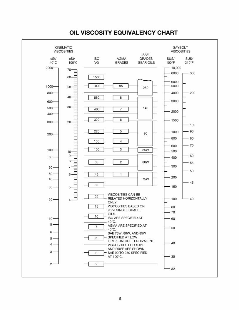
OIL VISCOSITY EQUIVALENCY CHART
2000
1000
800
600
500
400
300
200
100
80
60
50
40
30
20
10
8
6
5
4
3
2
70
60
50
40
30
20
10
8
5
4
9
7
6
1500
1000
680
460
320
220
150
100
68
8A
8
7
6
5
4
3
2
85W
250
140
90
80W
46
32
22
15
10
7
5
175W
3
2
300
200
150
100
80
70
60
50
40
35
32
400
500
600
800
1000
1500
2000
3000
4000
50006000
8000
10,000
cSt/40°C 100°C
cSt/ ISOVG
AGMAGRADES
GRADESGEAR OILS
SUS/100°F
SUS/210°F
SAE
KINEMATICVISCOSITIES
SAYBOLTVISCOSITIES
200
300
100
90
80
70
60
55
50
45
40VISCOSITIES CAN BERELATED HORIZONTALLYONLY.VISCOSITIES BASED ON96 VI SINGLE GRADEOILS.ISO ARE SPECIFIED AT40°C.AGMA ARE SPECIFIED AT40°C.SAE 75W, 80W, AND 85WSPECIFIED AT LOWTEMPERATURE. EQUIVALENTVISCOSITIES FOR 100°FAND 200°F ARE SHOWN.SAE 90 TO 250 SPECIFIEDAT 100°C.

6
GUIDELINES FOR SCXT REDUCER LONG-TERM STORAGE
During periods of long storage, or when waiting for delivery or installation of other equipment, special care should be taken to protect a gear reducer to have it ready to be in the best condition when placed into service.
By taking special precautions, problems such as seal leakage and reducer failure due to lack of lubrication, improper lubrication quantity, or contamination can be avoided. The following precautions will protect gear reducers during periods of extended storage:
Preparation:Drain oil from the unit. Add a vapor phase corrosion inhibiting 1. oil (VCI-105 oil by Daubert Chemical Co.) in accordance with Table 3.Seal the unit airtight. Replace the vent plug with a standard 2. pipe plug and wire the vent to the unit.Cover all unpainted exterior parts with a waxy rust 3. preventative compound that will keep oxygen away from the bare metal. (Non-Rust X-110 by Daubert Chemical Co. or equivalent)The instruction manuals and lubrication tags are paper and 4. must be kept dry. Either remove these documents and store them inside, or cover the unit with a durable waterproof cover which can keep moisture away.Protect reducer from dust, moisture, and other contaminants 5. by storing the unit in a dry area.In damp environments, the reducer should be packed inside 6. a moisture-proof container or an envelope of polyethylene containing a desiccant material. If the reducer is to be stored outdoors, cover the entire exterior with a rust preventative.
When placing the reducer into service:
Fill the unit to the proper oil level using a recommended 1. lubricant. The VCI oil will not affect the new lubricant.Clean the shaft extensions with petroleum solvents.2. Assemble the vent plug into the proper hole.3.
Follow the installation instructions provided in this manual.
Table 3 – Quantities of VCI #105 Oil
Reducer Size Quantity (Ounces / Milliliter)
SCXT1A 1 / 30
SCXT3B 1 / 30
SCXT2A 1 / 30
SCXT4B 1 / 30
SCXT5C 1 / 30
SCXT6A 2 / 59
SCXT7A 2 / 59
SCXT8A 3 / 89
REPLACEMENT OF PARTS
IMPORTANT: Using tools normally found in a maintenance department, a Dodge SCXT speed reducer can be disassembled and reassembled by careful attention to the instructions following.
Cleanliness is very important to prevent the introduction of dirt into the bearings and other parts of the reducer. A tank of clean solvent, an arbor press, and equipment for heating bearings and gears (for shrinking these parts on shafts) should be available.
Our factory is prepared to repair reducers for customers who do
not have proper facilities or who, for any reason, desire factory service.
The oil seals are contact lip seals. Considerable care should be used during disassembly and reassembly to avoid damage to the surface on which the seals rub.
The keyseat in the input shaft, as well as any sharp edges on the output hub should be covered with tape or paper before disassembly or reassembly. Also, be careful to remove any burrs or nicks on surfaces of the input shaft or output hub before disassembly or reassembly.
Ordering Parts: When ordering parts for reducer, specify reducer size number, reducer model number, part name, part number, and quantity.
It is strongly recommended that, when a pinion or gear is replaced, the mating pinion or gear is replaced also. If the large gear on the output hub must be replaced, it is recommended that an output hub assembly consisting of a gear assembled on a hub be ordered to ensure undamaged surfaces on the output hub where the output seals rub. However, if it is desired to use the old output hub, press the gear and bearing off and examine the rubbing surface under the oil seal carefully for possible scratching or other damage resulting from the pressing operation. To prevent oil leakage at the shaft oil seals, the smooth surface of the output hub must not be damaged.
If any parts must be pressed from a shaft or from the output hub, this should be done before ordering parts to make sure that none of the bearings or other parts are damaged in removal. Do not press against rollers or cage of any bearing.
Because old shaft oil seals may be damaged in disassembly, it is advisable to order replacements for these parts.
Removing Screw Conveyor Drive from Trough End
Disconnect an electrical power to the drive. Drain lubricant from reducer. Uncouple drive shaft and screw. Remove nuts from trough end studs. Support drive by means of hoist and carefully pull unit away from trough end to slide drive shaft out of screw.
Disassembly:Remove retainer bolt, lockwasher, and shaft retainer from 1. drive shaft. Pull drive shaft out of reducer from adapter side. Remove adapter.Position the reducer on its side and remove all housing 2. bolts. Drive dowel pins from housing. Using the three pry slots around the periphery of the flange, gently separate the housing halves. Open housing evenly to prevent damage to the parts inside.Lift input shaft, all gear assemblies, and bearing 3. assemblies from housing.Remove seals from housing.4. Remove bearings from shafts and hubs. Be careful not 5. to scratch or damage any assembly or seal area during bearing removal. The hub assembly can be disassembled for gear replacement but if scratching or grooving occurs on the hub, seal leakage will occur and the hub will need to be replaced.
Reassembly:Output Hub Assembly: Heat gear to 325°F to 350°F to 1. shrink onto hub. Heat bearings to 270°F to 290°F to shrink onto hub. Any damage to the hub surfaces where the oil seals rub will cause leakage, making it necessary to replace the hub.Countershaft Assembly: Heat gear to 325°F to 350°F and 2. bearings to 270°F to 290°F to shrink onto shaft.Input Shaft Assembly: Heat bearings 270°F to 290°F to 3. shrink onto shaft. Press bearings on shaft.

7
Drive the two dowel pins into place in the right-hand housing 4. half (backstop side).Place R.H. housing half on blocks to allow for protruding 5. end of output hub.Install all bearing cups in right-hand housing half, making 6. sure they are properly seated. SCXT1 and SCXT2 reducers use ball bearings on input and countershaft, tapered roller bearing cups are only used on the output bearings on these two sizes.Mesh output hub gear and small countershaft gear together 7. and set in place in housing. Set input shaft assembly in place in the housing. Make sure bearing rollers (cones) are properly seated in their cups.Make sure both housing halves are clean. Apply a continuous 8. 1/8” diameter bead of Dow Corning RTV732 sealant on the flange surface of the R.H. housing (make sure RTV is placed around all bolt holes). Set the left-hand housing half into position onto the dowel pins and gently tap with a soft hammer (rawhide, not lead hammer) until housing bolts can be used to draw housing halves together. Make sure reducer shafts do not bind while tightening housing bolts. Torque housing bolts per torque values listed in Table 5.Place the output bearing cup into the housing and tap into 9. place. Install the output seal carrier and draw down with two bolts 180° apart to 50 inch pounds of torque. Loosen both bolts then retighten finger tight only. Measure the clearance between the housing and carrier flange at each bolt and average the two values. Add 0.010” to the average reading and make up shim pack. Install shim pack between the carrier flange and the reducer housing. Torque the bolts to the value shown in Table 5. Using a magnetic base and dial indicator, check the axial end play. Add or remove shims until the axial endplay reading of the output hub is per Table 4.Repeat step 9 above for installing and adjusting the 10. countershaft and input bearings on sizes 3 through 8. Adjust the axial endplay per Table 4.Install input and output seals. Lightly coat the seal lips 11. with Mobilith AW2 All-Purpose grease or equivalent. The possibility of damage and consequent oil leakage can be decreased by covering all sharp edges with tape prior to seal installation. Seals should be pressed or tapped with a soft hammer evenly into place in the reducer housing, applying pressure only on the outer edge of the seals.
Extreme care should be used when installing seals to avoiddamage due to contact with sharp edges on the input shaft or output hub. A slight oil leak at the seals may be evident during initial running, but should disappear unless seals have been damaged.Install backstop cover. Make sure all bolts are tightened to 12. the correct torque values listed in Table 5.
Table 4 - Bearing Adjustment Tolerances
Reducer SizeBearing Endplay Values
Input Countershaft Output
SCXT1A N/A N/A .0005-.003 Loose
SCXT2A N/A N/A .0005-.003 Loose
SCXT3B .002-.004 Loose .0005-.003 Loose .0005-.003 Loose
SCXT4B .002-.004 Loose .0005-.003 Loose .0005-.003 Loose
SCXT5C .002-.004 Loose .0005-.003 Loose .0005-.003 Loose
SCXT6A .002-.004 Loose .0005-.003 Loose .0005-.003 Loose
SCXT7A .002-.004 Loose .0005-.003 Loose .0005-.003 Loose
SCXT8A .002-.004 Loose .0005-.003 Loose .0005-.003 Loose
Table 5 – Recommended Bolt Torque Values
Reducer SizeRecommended Torque (ft. lbs.)
HousingBolts
Output SealCarrier
C/S BearingCover
Input SealCarrier
SCXT1A 30 - 27 N/A N/A N/A
SCXT2A 30 - 27 N/A N/A N/A
SCXT3B 50 - 45 17 – 15 17 – 15 17 – 15
SCXT4B 50 - 45 30 – 27 30 – 27 30 – 27
SCXT5C 75 - 68 30 – 27 30 – 27 30 – 27
SCXT6A 75 - 68 30 – 27 30 – 27 30 – 27
SCXT7A 150 - 135 50 - 45 50 - 45 50 - 45
SCXT8A 150 - 135 30 – 27 30 – 27 30 – 27
Reducer SizeRecommended Torque (ft. lbs.)
Drive Shaft Adapter Bolts Backstop Cover
SCXT1A 150-135 30-27 5 – 4
SCXT2A 150-135 50-45 5 – 4
SCXT3B 260-234 75-68 5 – 4
SCXT4B 260-234 150-135 8 – 7
SCXT5C 260-234 150-135 8 – 7
SCXT6A 640-576 150-135 8 – 7
SCXT7A 640-576 150-135 8 – 7
SCXT8A 640-576 183-165 8 – 7
8
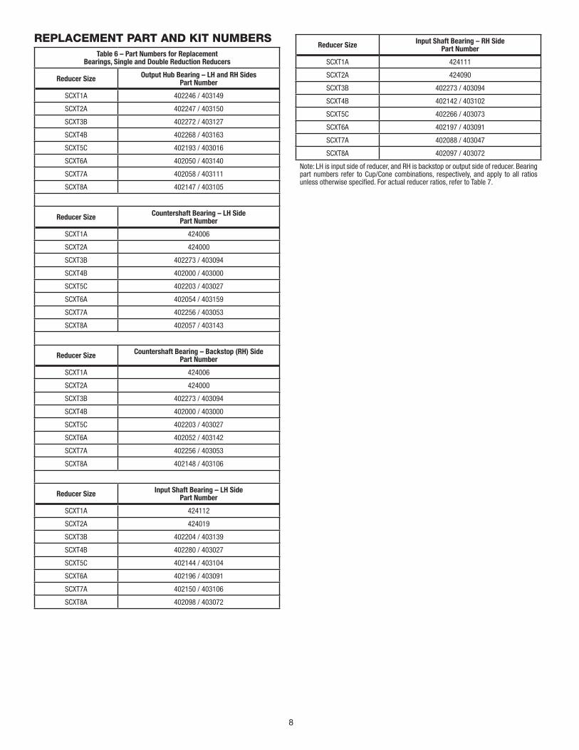
REPLACEMENT PART AND KIT NUMBERSTable 6 – Part Numbers for Replacement
Bearings, Single and Double Reduction Reducers
Reducer Size Output Hub Bearing – LH and RH Sides Part Number
SCXT1A 402246 / 403149
SCXT2A 402247 / 403150
SCXT3B 402272 / 403127
SCXT4B 402268 / 403163
SCXT5C 402193 / 403016
SCXT6A 402050 / 403140
SCXT7A 402058 / 403111
SCXT8A 402147 / 403105
Reducer Size Countershaft Bearing – LH Side Part Number
SCXT1A 424006
SCXT2A 424000
SCXT3B 402273 / 403094
SCXT4B 402000 / 403000
SCXT5C 402203 / 403027
SCXT6A 402054 / 403159
SCXT7A 402256 / 403053
SCXT8A 402057 / 403143
Reducer Size Countershaft Bearing – Backstop (RH) SidePart Number
SCXT1A 424006
SCXT2A 424000
SCXT3B 402273 / 403094
SCXT4B 402000 / 403000
SCXT5C 402203 / 403027
SCXT6A 402052 / 403142
SCXT7A 402256 / 403053
SCXT8A 402148 / 403106
Reducer Size Input Shaft Bearing – LH SidePart Number
SCXT1A 424112
SCXT2A 424019
SCXT3B 402204 / 403139
SCXT4B 402280 / 403027
SCXT5C 402144 / 403104
SCXT6A 402196 / 403091
SCXT7A 402150 / 403106
SCXT8A 402098 / 403072
Reducer Size Input Shaft Bearing – RH SidePart Number
SCXT1A 424111
SCXT2A 424090
SCXT3B 402273 / 403094
SCXT4B 402142 / 403102
SCXT5C 402266 / 403073
SCXT6A 402197 / 403091
SCXT7A 402088 / 403047
SCXT8A 402097 / 403072
Note: LH is input side of reducer, and RH is backstop or output side of reducer. Bearing part numbers refer to Cup/Cone combinations, respectively, and apply to all ratios unless otherwise specified. For actual reducer ratios, refer to Table 7.

9
Table 8 - Actual Ratios
Reducer SizeNominal Ratio
9:1 15:1 25:1
SCXT1A 9.44 15.35 25.64
SCXT2A 9.25 14.10 23.46
SCXT3B 8.91 14.88 24.71
SCXT4B 9.67 15.13 24.38
SCXT5C 8.95 15.40 25.56
SCXT6A 9.20 15.33 25.13
SCXT7A 9.61 15.23 24.59
SCXT8A N/A 15.08 24.62
Table 7 - Replacement Parts Kit Numbers
Reducer Size Ratio Seal Kit
Ouput Hub
Assembly
CountershaftAssembly Bearing Kit(s)
SCXT1A
9:1
272711 391029
392100
N/A15:1 392090
25:1 392091
SCXT2A
9:01
272712 392105
392101
N/A15:1 392092
25:1 392093
SCXT3B
9:1
389720 389702
389729389587 Input389588 C/S
389589 Output15:1 389700
25:1 389701
SCXT4B
9:1
389721 389709
389730389590 Input389591 C/S
389592 Output15:1 389707
25:1 389708
SCXT5C
9:1
389722 389716
389731389593 Input389595 C/S
389596 Output15:1 389714
25:1 389715
SCXT6A
9:1
246340 390988
392140
N/A15:1 391171
25:1 391186
SCXT7A
9:1
247345 390990
392141
N/A15:1 391196
25:1 391197
SCXT8A
15:1
248340 390993
391184
N/A25:1 391185
24:1 390998
Seal Kit consists of Input Seal, Output Seals, Backstop Cover Gasket and RTV Sealant.Output Hub Assembly consists of Output Hub, Output Gear and Gear Key.Countershaft Assembly consists of Countershaft Pinion, Countershaft Gear and Gear Key.Bearing Kit consists of LH and RH Output Bearing Cup/Cone, LH and RH CountershaftBearing Cup/Cone (double reduction only) and LH and RH Input Bearing Cup/Cone.

10
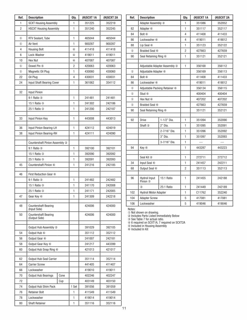
Parts for SCXT / HSCXT 1A and 2A Double Reduction Screw Conveyor and Hydroil Screw Conveyor Drive
11
Ref. Description Qty. (H)SCXT 1A (H)SCXT 2A
1 SCXT Housing Assembly 1 351225 352219
2 HSCXT Housing Assembly 1 351240 352245
① RTV Sealant, Tube 1 465044 465044
① Air Vent 1 900287 900287
4 Housing Bolt ④ 411418 411418
6 Lock-Washer ④ 419011 419011
10 Hex Nut ④ 407087 407087
① Dowel Pin ⑤ 2 420063 420063
① Magnetic Oil Plug 1 430060 430060
22 Oil Plug 4 430031 430031
24 Input Shaft Bearing Cover 1 361062 354112
32 Input Pinion
9:1 Ratio ③ 1 241481 241481
15:1 Ratio ③ 1 241302 242186
25:1 Ratio ③ 1 241200 242187
33 Input Pinion Key 1 443008 443013
36 Input Pinion Bearing-LH 1 424112 424019
38 Input Pinion Bearing-RH 1 424111 424090
Countershaft Pinion Assembly ②
9:1 Ratio ③ 1 392100 392101
15:1 Ratio ③ 1 392090 392092
25:1 Ratio ③ 1 392091 392093
45 Countershaft Pinion ⑥ 1 241216 242185
46 First Reduction Gear ⑥
9:1 Ratio ③ 1 241482 242482
15:1 Ratio ③ 1 241170 242008
25:1 Ratio ③ 1 241171 242005
47 Gear Key ⑥ 1 241309 242218
48 Countershaft Bearing(Input Side)
424006 424000
50 Countershaft Bearing(Output Side)
424006 424000
Output Hub Assembly ② 391029 392105
54 Output Hub ⑥ 351112 352112
56 Output Gear ⑥ 241007 242181
58 Output Gear Key ⑥ 241217 443399
60 Output Hub Snap Ring ⑥ 421013 421017
62 Output Hub Seal Carrier 351114 352114
64 Carrier Screw 441405 411407
66 Lockwasher 419010 419011
70 Output Hub Bearings Cone 402246 402247
72 Cup 403149 403150
74 Output Hub Shim Pack 1 Set 391056 391059
76 Retainer Bolt 1 411549 411549
78 Lockwasher 1 419014 419014
80 Shaft Retainer 1 351116 352116
Ref. Description Qty. (H)SCXT 1A (H)SCXT 2A
Adapter Assembly ② 1 351086 352052
82 Adapter ⑥ 1 351117 352117
84 Bolt ⑥ 4 411408 411433
86 Lockwasher ⑥ 4 419011 419012
88 Lip Seal ⑥ 1 351123 352122
① Braided Seal ⑥ 2 427663 427659
90 Seal Retaining Ring ⑥ 1 351121 352121
Adjustable Adapter Assembly ② 1 356168 356112
① Adjustable Adapter ⑥ 356169 356113
84 Bolt ⑥ 411408 411433
86 Lockwasher ⑥ 419011 419012
① Adjustable Packing Retainer ⑥ 356134 356115
① Stud ⑥ 400404 400404
① Hex Nut ⑥ 407202 407202
① Braided Seal ⑥ 427663 427659
90 Seal Retaining Ring ⑥ 351121 352121
92 Drive 1-1/2” Dia. 1 351094 352090
Shaft ② 2” Dia. 1 351095 352091
2-7/16” Dia. 1 351096 352092
3” Dia. 1 351097 352093
3-7/16” Dia. 1 --- ---
94 Key ⑥ 1 443287 443223
Seal Kit ② 1 272711 272712
34 Input Seal ⑥ 1 241457 242211
68 Output Seal ⑥ 2 351113 352113
96 Hydroil Input Pinion ③
15:1 Ratio 1 241455 242188
③ 25:1 Ratio 1 241449 242189
102 Hydroil Motor Adapter 1 C11762 352240
104 Adapter Screw 5 417081 417081
106 Lockwasher 5 419046 419046
Notes:① Not shown on drawing.② Includes Parts Listed Immediately Below③ See Table 7 for actual ratio.④ 6 required on SCXT1A, 7 required on SCXT2A⑤ Included in Housing Assembly⑥ Included In Kit

12
Parts for SCXT / HSCXT 3B, 4B and 5C Double Reduction Screw Conveyor and Hydroil Screw Conveyor Drive

13
Ref. Description Qty. (H)SCXT3B
(H)SCXT4B
(H)SCXT5C
1 Housing Assembly 1 243538 244569 245589
① RTV Sealant, Tube 1 465044 465044 465044
① Air Vent 1 900287 900287 904287
4 Housing Bolt 8 411440 411442 411464
6 Lock-Washer 8 419012 419012 419013
10 Hex Nut 8 407089 407089 407091
① Dowel Pin ④ 2 420063 420063 304624
① Magnetic Oil Plug 1 430060 430060 430062
14 Oil Plug 4 430031 430031 430033
24 Input Shaft Bearing Cover 1 243560 244493 245226
26 Bearing Cover Screw 4 416524 411035 411394
27 Lockwasher 4 --- 419009 419009
28 Input Bearing Shim Pack 2Sets
389704 389711 389732
29 Input Shaft Seal Carrier 1 243543 244577 245597
32 Input Pinion
9:1 Ratio ③ 1 243549 244579 245599
15:1 Ratio ③ 1 243550 244580 245600
25:1 Ratio ③ 1 243551 244581 245601
33 Input Pinion Key 1 443032 443082 443096
Input Bearing Kit ② 389587 389590 389594
36 Input Bearing-LH ⑤ Cone 1 402204 402280 402144
37 ⑤ Cup 1 403139 403027 403104
38 Input Bearing-RH ⑤ Cone 1 402273 402142 402266
39 ⑤ Cup 1 403094 403102 403073
44 Countershaft Bearing ShimPack
2Sets
389705 389712 389718
Countershaft Assembly ②
9:1 Ratio ③ 1 389729 389730 389731
15:1 Ratio ③ 1 389700 389707 389714
25:1 Ratio ③ 1 389701 389708 389715
45 Countershaft with Pinion ⑤ 1 243555 244590 245596
First Reduction Gear ⑤
9:1 Ratio ③ 1 243237 244482 245482
15:1 Ratio ③ 1 243238 244214 245214
25:1 Ratio ③ 1 243239 244212 245212
47 Gear Key ⑤ 1 D8242 D8243 D8243
Countershaft Bearing Kit ② 1 389588 389591 389595
48 Countershaft Bearing - LH ⑤ Cone 1 402273 402000 402203
49 ⑤ Cup 1 403094 403000 403027
50 Countershaft bearing - RH ⑤ Cone 1 402273 402000 402203
51 ⑤ Cup 1 403094 403000 403027
Output Hub Assembly ② 1 389702 389709 389716
54 Output Hub ⑤ 1 243557 244589 245591
56 Output Gear ⑤ 1 243570 244188 245186
58 Output Gear Key ⑤ 1 243216 354087 355064
62 Output Hub Seal Carrier 1 243547 244591 245592
64 Carrier Screw 6 411390 411407 411407
66 Lockwasher 6 419010 419011 419011
Ref. Description Qty. (H)SCXT3B
(H)SCXT4B
SCXT5C
Output Bearing Kit ② 1 389589 389592 389596
70 Output Hub Bearings ⑤ Cone 2 402272 402268 402193
72 ⑤ Cup 2 403127 403163 403016
74 Output Hub Shim Pack 2 Sets
389706 389713 389719
76 Retainer Bolt 1 411551 411551 411551
78 Lockwasher 1 419016 419016 419016
80 Shaft Retainer 1 353053 354088 355065
Adapter Assembly ② 1 353047 354121 355072
82 Adapter ⑤ 1 353081 354081 355047
84 Bolt ⑤ 4 411456 411483 411483
86 Lockwasher ⑤ 4 419013 419014 419014
88 Lip Seal ⑤ 1 353085 354115 355067
① Braided Seal ⑤ 2 427658 427664 427674
90 Seal Retaining Ring ⑤ 1 353054 354089 355066
Adjustable Adapter Assembly ② 1 356163 356149 356158
① Adjustable Adapter ⑤ 1 356164 356150 356159
84 Bolt ⑤ 4 411456 411483 411483
86 Lockwasher ⑤ 4 419013 419014 419014
① Adjustable Packing Retainer ⑤ 1 356166 356152 356161
① Stud ⑤ 2 400404 400404 400404
① Hex Nut ⑤ 2 407202 407202 407202
① Braided Seal ⑤ 3 427658 427664 427674
90 Seal Retaining Ring ⑤ 1 353054 354089 355066
92 Drive 1-1/2” Dia. 1 243562 244594 ---
Shaft ② 2” Dia. 1 243563 244595 355175
2-7/16” Dia. 1 243564 244596 355176
3” Dia. 1 243565 244597 355177
3-7/16” Dia. 1 --- 244598 355178
94 Key ⑤ 1 443089 443114 443239
Seal Kit ② 1 389720 389721 389722
34 Input Seal ⑤ 1 243558 244524 355011
68 Output Seal ⑤ 2 243578 244673 245545
25 Input Bearing Cover Gasket ⑤ 1 243561 244593 245220
96 Hydroil Input Pinion
15:1 Ratio ③ 1 243553 244583 245603
25:1 Ratio ③ 1 243554 244584 245604
102 Hydroil Motor Adapter
15:1 Ratio ③ 1 243539 244572 245606
25:1 Ratio ③ 1 243541 244572 245607
104 Adapter Screw 4 417081 417108 415023
106 Lockwasher
15:1 Ratio ③ 4 419046 419047 ---
25:1 Ratio ③ 4 419046 419047 419047
Notes:① Not shown on drawing.② Includes Parts Listed Immediately Below③ See Table 7 for actual ratio.④ Included in Housing Assembly⑤ Part of Kit Listed above

14
Parts for SCXT / HSCST 6A thru 8A Double ReductionScrew Conveyor and Hydroil Screw Conveyor Drive

15
Ref. Description Qty. (H)SCXT6A
(H)SCXT7A
SCXT8A
1 Housing Assembly 1 356279 356280 248487
① RTV Sealant, Tube 1 465044 465044 465044
① Air Vent 1 904287 904287 904287
① Air Vent Bushing 1 --- 430079 430079
4 Housing Bolt ⑤ 411466 411498 411499
6 Lock-Washer ⑤ 419013 419016 419016
10 Hex Nut ⑤ 407091 407095 407095
12 Dowel Pin ⑦ 2 304624 304624 304624
① Magnetic Oil Plug 1 430062 430064 430064
① Oil Plug 1 430033 430035 430035
24 Input Shaft Bearing Cover 4 246226 246226 248226
26 Bearing Cover Screw 6 411394 411394 411394
27 Lockwasher 6 419009 419009 419009
28 Input Bearing Shim Pack 2Sets
391164 390420 390038
29 Input Shaft Seal Carrier 1 246184 247320 258023
32 Input Pinion
9:1 Ratio ③ 1 246481 247479 248482
15:1 Ratio ③ 1 246290 247370 248370
25:1 Ratio ③ 1 246291 247371 248371
33 Input Pinion Key 1 443113 443127 443133
36 Input Bearing-LH Cone 1 402196 402150 402098
37 Cup 1 403091 430106 403072
38 Input Bearing-RH Cone 402197 402088 402097
39 Cup 403091 403047 403072
44 Countershaft Bearing ShimPack
2Sets
391165 390429 391182
Countershaft Assembly ②
9:1 Ratio ④ 1 392140 392141 ---
15:1 Ratio ④ 1 391171 391196 391184
25:1 Ratio ④ 1 391186 391197 391185
45 Countershaft with Pinion ③ 1 246294 247002 248002
46 First Reduction Gear ③
9:1 Ratio ④ 1 246482 247478 248483
15:1 Ratio ④ 1 246292 247008 248213
25:1 Ratio ④ 1 246293 247005 248214
47 Gear Key ③ 1 245218 247218 248218
48 Countershaft Bearing-LH
Cone 1 402054 402256 402057
49 Cup 1 403159 403053 403143
50 Countershaft Bearing-RH
Cone 1 402052 402256 402148
51 Cup 1 403142 403053 403106
Output Hub Assembly ② 390988 390990 390993
54 Output Hub ③ 246338 247338 248332
56 Output Gear ③ 246295 247215 248215
58 Output Gear Key ③ 245217 245217 248217
Ref. Description Qty. (H)SCXT6A
(H)SCXT7A
SCXT8A
62 Output Hub Seal Carrier 1 246187 247315 258021
64 Carrier Screw ⑥ 411408 411433 411408
66 Lockwasher ⑥ 419011 419012 419011
Output Hub Bearings Cone 2 402050 402058 402147
Cup 2 403140 403111 403105
Output Hub Shim Pack 2Sets
391187 390444 390048
76 Retainer Bolt 1 411552 411552 411552
78 Lockwasher 1 419020 419020 419020
80 Shaft Retainer 1 356047 356191 248486
Adapter Assembly ② 1 356055 356187 248470
82 Adapter ② 1 356049 356189 248471
84 Bolt ② 4 411487 411496 411496
86 Lockwasher ② 4 419014 419016 419016
88 Lip Seal ② 1 355054 355054 355054
① Braided Seal ② 2 427687 427687 ---
90 Seal Retaining Ring ② 1 356054 356054 248481
Adjustable Adapter Assembly ② 1 356154 356192 ---
① Adjustable Adapter ③ 1 356155 356193 ---
84 Bolt ③ 4 411487 411496 ---
86 Lockwasher ③ 4 419014 419016 ---
① Adjustable Packing Retainer ③ 1 356157 356157 ---
① Stud ③ 2 400404 400404 ---
① Hex Nut ③ 2 407202 407202 ---
① Braided Seal ③ 3 427687 427687 ---
90 Seal Retaining Ring ③ 1 356054 356054 ---
92 Drive 1-1/2” Dia. 1 356040 356180 ---
Shaft ② 2” Dia. 1 356041 356181 ---
2-7/16” Dia. 1 356042 356182 ---
3” Dia. 1 356043 356183 248473
3-7/16” Dia. 1 356044 356184 248474
94 Key ③ 1 443288 443289 443289
Seal Kit ② 1 246340 247345 248340
Input Seal ③ 1 242210 242210 248211
Output Seal ③ 2 246310 247310 258019
Input Bearing Cover Gasket ③ 1 246220 246220 248220
96 Hydroil Input Pinion Ratio ④
15:1 1 246230 247463 ---
Ratio ④ 25:1 1 246286 247462 ---
102 Hydroil Motor Adapter 1 246465 247464 ---
104 Adapter Screw 6 417108 417141 ---
106 Lockwasher 6 419047 419048 ---
Notes:① Not shown on drawing.② Includes Parts Listed Immediately Below③ Included in Kit④ See Table 7 for actual ratio.⑤ 8 required on SCXT6A and SCXT7A, 11 required on SCXT8A, ⑥ 18 Required on SCXT6A, 20 Required on SCXT7A, and 24 Required on SCXT8A. ⑦ Included in Housing Assembly

World Headquarters
P.O. Box 2400, Fort Smith, AR 72902-2400 U.S.A., Ph: (1) 479.646.4711, Fax (1) 479.648.5792, International Fax (1) 479.648.5895
Dodge Product Support
6040 Ponders Court, Greenville, SC 29615-4617 U.S.A., Ph: (1) 864.297.4800, Fax: (1) 864.281.2433
www.baldor.com
© Baldor Electric CompanyMN1611 (499305)
All Rights Reserved. Printed in USA.4/10 TCP 25,000*1611-0410*
Top Related