


Languages
Pages
Legal

The features and characteristics of the most important methods of
measuring the flowrate and quantities of flowing fluids are described
and compared.
Numerous practical details provide the user with valuable information
about flow metering in industrial applications.
Ind
ustr
ial flo
w m
easu
rem
en
t
Industrial flow measurement Basics and practice
D1
84
B0
75
U0
2 R
ev.
08
09
.20
11

This document including all its parts is copyright protected.
Translation, reproduction and distribution in any form – including edited or excerpts – in particularreproductions, photo-mechanical, electronic or storage in information retrieval and data processingor network systems without the express consent of the copyright holder is expressly prohibited and violations will be prosecuted.
The editor and the team of authors kindly request your understanding that, due to the large amount of data described, they cannot assume any liability for the correctness of all these data.
In case of doubt, the cited source documents, standards and regulations are valid.
© 2011 ABB Automation Products GmbH
Industrial Flow MeasurementBasics and Practice
Authors: F. Frenzel, H. Grothey, C. Habersetzer, M. Hiatt, W. Hogrefe, M. Kirchner, G. Lütkepohl, W. Marchewka, U. Mecke, M. Ohm, F. Otto, K.-H. Rackebrandt, D. Sievert, A. Thöne, H.-J. Wegener, F. Buhl, C. Koch, L. Deppe, E. Horlebein, A. Schüssler, U. Pohl, B. Jung, H. Lawrence, F. Lohrengel, G. Rasche, S. Pagano, A. Kaiser, T. Mutongo
ABB Automation Products GmbH

Introduction
In the recent decades, the market for the products of the industrial process industrieshas changed greatly. The manufacture of mass products has shifted to locations whereraw materials are available economically. Competitive pressures have forced a swingto specialization as well as to an ability to adapt to customers desires. The systems aredesigned so that the economic data, such as raw material properties, raw materialcosts, batch sizes, are quickly integrated into the processes. An important consider-ation is the assurance and improvement of product quality.
The operation of such systems requires a high degree of automation. With the assis-tance of process technology the control of the procedures can be optimized and per-sonnel requirements minimized. The process control technology assures that processcycles are documented so that the quality of the product is always traceable.
The most important prerequisite for automation is knowledge of the actual process pa-rameters, which can be ascertained utilizing measurement instruments. If the actionsdependent on the measurements are to be realized then the specifications must natu-rally be qualitatively high. Therefore, the measurement instrument requires:
• high accuracy• easily understandable functionality• easy operation and maintenance• testability even without a test bench• self monitoring • error signalling / self-diagnostics• communication ability
The planner of an industrial process system assumes in advance that the measure-ment error limits will be satisfied. However, it is not always possible to divorce oneselffrom the problems associated with the measuring point.
This publication for industrial flow measurement aims at supporting practitioners insolving their versatile and demanding tasks. At the same time, it is intended to providea vivid overview of the basic measuring principles and their limitations to interestednewcomers.
Advanced developments and a well-structured, global network of ABB research cen-ters are the basis for innovative products and solutions. ABB products are manufac-tured at powerful production sites by experienced and committed staff using the latestmethods and technologies. Competent and friendly sales support and after-sales ser-vice round off ABB's range of products and services.
5

We hope you will enjoy reading this publications and take advantage of its practicaluse. We would like to thank all authors who have contributed to creating this publica-tion. Any suggestions and comments from your side are welcome and will flow into thedevelopment process of new technological solutions.
ABB – Power and productivity for a better world
6
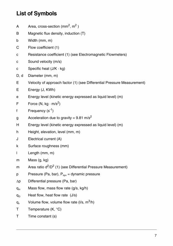
List of Symbols
A Area, cross-section (mm2, m2 )
B Magnetic flux density, induction (T)
b Width (mm, m)
C Flow coefficient (1)
c Resistance coefficient (1) (see Electromagnetic Flowmeters)
c Sound velocity (m/s)
c Specific heat (J/K · kg)
D, d Diameter (mm, m)
E Velocity of approach factor (1) (see Differential Pressure Measurement)
E Energy (J, KWh)
e Energy level (kinetic energy expressed as liquid level) (m)
F Force (N, kg · m/s2)
f Frequency (s-1)
g Acceleration due to gravity = 9.81 m/s2
H Energy level (kinetic energy expressed as liquid level) (m)
h Height, elevation, level (mm, m)
J Electrical current (A)
k Surface roughness (mm)
l Length (mm, m)
m Mass (g, kg)
m Area ratio d2/D2 (1) (see Differential Pressure Measurement)
p Pressure (Pa, bar), Pdyn = dynamic pressure
Δp Differential pressure (Pa, bar)
qm Mass flow, mass flow rate (g/s, kg/h)
qQ Heat flow, heat flow rate (J/s)
qv Volume flow, volume flow rate (l/s, m3/h)
T Temperature (K, °C)
T Time constant (s)
7
t Time (s)
U Electrical voltage (V)
V Volume (mm3, m3, l)
v Velcocity (m/s)
W Weighting factor (1) (see Electromagnetic Flowmeters)
β Diameter ratio d/D ;1< (see Differential Pressure Measurement)
γ Thermal volume expansion coefficient (K-1)
Δ Difference, spec. differential pressure Δp
ε Expansion coefficient (1)
η Dynamic viscosity (Pa · s)
χ Electrical conductivity (S/cm)
λ Resistance coefficient, coefficient of friction (1) (see Free SurfaceMeasurements)
μ Flow coefficient (1), (see Weir)
ν Kinematic viscosity (m2/s)
ρ Density (kg/m3, g/cm3)
Φ Magnetic flux (Wb, Vs)
ω Angular velocity (s-1)
Fr Froude number (1)
Re Reynolds number (1)
St Strouhal number (1)
VUZ Viscosity Influence Number (1)
8

Content Page
1 Introduction to the Physics of Flow Rate and Total Flow Measurements 131.1 Measured Variables . . . . . . . . . . . . . . . . . . . . . . . . . . . . . . . . . . . . . . . . . . . 131.2 Fluid Mechanics Concepts . . . . . . . . . . . . . . . . . . . . . . . . . . . . . . . . . . . . . . 151.2.1 Viscosity . . . . . . . . . . . . . . . . . . . . . . . . . . . . . . . . . . . . . . . . . . . . . . . . . . . . 151.2.2 Reynolds Number . . . . . . . . . . . . . . . . . . . . . . . . . . . . . . . . . . . . . . . . . . . . . 151.2.3 Flow Regimes . . . . . . . . . . . . . . . . . . . . . . . . . . . . . . . . . . . . . . . . . . . . . . . . 161.2.4 Flow Separation . . . . . . . . . . . . . . . . . . . . . . . . . . . . . . . . . . . . . . . . . . . . . . 171.2.5 Energy Equations and Flow Rate . . . . . . . . . . . . . . . . . . . . . . . . . . . . . . . . . 191.2.6 Channel Hydraulics . . . . . . . . . . . . . . . . . . . . . . . . . . . . . . . . . . . . . . . . . . . . 23
2 Flow Rate and Total Flow Measurement of Gases and Liquids . . . . . . . 292.1 Volume Totalizers . . . . . . . . . . . . . . . . . . . . . . . . . . . . . . . . . . . . . . . . . . . . . 302.1.1 Oval Gear Totalizers . . . . . . . . . . . . . . . . . . . . . . . . . . . . . . . . . . . . . . . . . . 302.1.2 Oscillating Piston Totalizers . . . . . . . . . . . . . . . . . . . . . . . . . . . . . . . . . . . . . 332.1.3 Lobed Impeller Gas Totalizers . . . . . . . . . . . . . . . . . . . . . . . . . . . . . . . . . . . 362.1.4 Turbine Totalizers . . . . . . . . . . . . . . . . . . . . . . . . . . . . . . . . . . . . . . . . . . . . . 382.1.5 Vortex Flowmeters . . . . . . . . . . . . . . . . . . . . . . . . . . . . . . . . . . . . . . . . . . . . 452.1.6 Swirl Flowmeters . . . . . . . . . . . . . . . . . . . . . . . . . . . . . . . . . . . . . . . . . . . . . . 572.2 Flowmeters . . . . . . . . . . . . . . . . . . . . . . . . . . . . . . . . . . . . . . . . . . . . . . . . . . 672.2.1 Flowmeters for Differential Pressure Measurement . . . . . . . . . . . . . . . . . . . 672.2.2 Compact Orifice Flowmeters . . . . . . . . . . . . . . . . . . . . . . . . . . . . . . . . . . . . . 782.2.3 Wedge Meters for Critical Applications . . . . . . . . . . . . . . . . . . . . . . . . . . . . . 792.2.4 Pitot Flowmeters . . . . . . . . . . . . . . . . . . . . . . . . . . . . . . . . . . . . . . . . . . . . . . 822.2.5 Variable Area Flowmeters . . . . . . . . . . . . . . . . . . . . . . . . . . . . . . . . . . . . . . 852.2.6 Electromagnetic Flowmeters . . . . . . . . . . . . . . . . . . . . . . . . . . . . . . . . . . . . 1022.2.7 Ultrasonic Flowmeters . . . . . . . . . . . . . . . . . . . . . . . . . . . . . . . . . . . . . . . . 1372.2.8 Coriolis Mass Flowmeters . . . . . . . . . . . . . . . . . . . . . . . . . . . . . . . . . . . . . 1402.2.9 Thermal Mass Flowmeters for Gases . . . . . . . . . . . . . . . . . . . . . . . . . . . . . 1512.3 Flow in Open Channels and Free Surface Pipelines . . . . . . . . . . . . . . . . . . 1572.3.1 Flow Measurement in Open Channels . . . . . . . . . . . . . . . . . . . . . . . . . . . . 1572.3.2 Flow Measurement in Free Surface Pipelines . . . . . . . . . . . . . . . . . . . . . . . 165
3 Regulations and Requirements Regarding Quality, Environment, Safety and Data Protection . . . . . . . . . . . . . . . . . . . . . . . . . . . . . . . . . . . 173
3.1 Integrated Management System . . . . . . . . . . . . . . . . . . . . . . . . . . . . . . . . . 1733.2 Degrees of Protection per EN 60529 (Excerpts from the Standard Sheet) . 1763.3 Requirements Regarding Interference Immunity (EMC) . . . . . . . . . . . . . . . 1793.4 Explosion Protection . . . . . . . . . . . . . . . . . . . . . . . . . . . . . . . . . . . . . . . . . . 1823.4.1 International Orientation of Explosion Protection . . . . . . . . . . . . . . . . . . . . 1833.4.2 Terms and Definitions . . . . . . . . . . . . . . . . . . . . . . . . . . . . . . . . . . . . . . . . . 1843.4.3 Types of Protection in Europe and North America . . . . . . . . . . . . . . . . . . . 1913.4.4 Approvals According to the FM Approval Standards . . . . . . . . . . . . . . . . . . 1963.4.5 Approvals in Accordance with the CSA Standards . . . . . . . . . . . . . . . . . . . 1963.4.6 Free Movement of Goods Related to Explosion-Proof Electrical Devices . 197
9

3.4.7 Identification of Equipment . . . . . . . . . . . . . . . . . . . . . . . . . . . . . . . . . . . . . 1973.5 GOST Approvals for Flow Measurement . . . . . . . . . . . . . . . . . . . . . . . . . . 1993.5.1 Russia . . . . . . . . . . . . . . . . . . . . . . . . . . . . . . . . . . . . . . . . . . . . . . . . . . . . . 1993.5.2 Belarus, Ukraine and Kazakhstan . . . . . . . . . . . . . . . . . . . . . . . . . . . . . . . . 2053.6 SIL - Functional Safety Standards . . . . . . . . . . . . . . . . . . . . . . . . . . . . . . . 2073.7 Pressure Equipment Directive 97/23/EC . . . . . . . . . . . . . . . . . . . . . . . . . . . 2093.8 Corrosion . . . . . . . . . . . . . . . . . . . . . . . . . . . . . . . . . . . . . . . . . . . . . . . . . . . 2133.9 Data Transmission . . . . . . . . . . . . . . . . . . . . . . . . . . . . . . . . . . . . . . . . . . . 2143.9.1 Standardized Pneumatic Signal . . . . . . . . . . . . . . . . . . . . . . . . . . . . . . . . . 2143.9.2 Standardized Electrical Analog Signal . . . . . . . . . . . . . . . . . . . . . . . . . . . . 2153.9.3 Switch Outputs . . . . . . . . . . . . . . . . . . . . . . . . . . . . . . . . . . . . . . . . . . . . . . 2153.9.4 HART Protocol . . . . . . . . . . . . . . . . . . . . . . . . . . . . . . . . . . . . . . . . . . . . . . 2163.9.5 Fieldbus in Process Automation . . . . . . . . . . . . . . . . . . . . . . . . . . . . . . . . . 2183.9.6 FOUNDATION Fieldbus . . . . . . . . . . . . . . . . . . . . . . . . . . . . . . . . . . . . . . . 2203.10 Calibration and Official Verification . . . . . . . . . . . . . . . . . . . . . . . . . . . . . . . 2213.10.1 Why Calibrate? . . . . . . . . . . . . . . . . . . . . . . . . . . . . . . . . . . . . . . . . . . . . . . 2213.10.2 Terms and Definitions . . . . . . . . . . . . . . . . . . . . . . . . . . . . . . . . . . . . . . . . . 2213.10.3 Methods of Flow Calibration . . . . . . . . . . . . . . . . . . . . . . . . . . . . . . . . . . . . 2223.10.4 Test Bench for Liquid Flow Measurement . . . . . . . . . . . . . . . . . . . . . . . . . . 2233.10.5 Test Bench for Gas Flow Measurement . . . . . . . . . . . . . . . . . . . . . . . . . . . 2253.10.6 Approvals of Test Benches and Products . . . . . . . . . . . . . . . . . . . . . . . . . . 2273.10.7 Calibration Possibilities at ABB . . . . . . . . . . . . . . . . . . . . . . . . . . . . . . . . . . 2303.10.8 Measuring Instruments Directive (MID) . . . . . . . . . . . . . . . . . . . . . . . . . . . . 2333.10.9 OIML (Organisation Internationale de Métrologie Légale) . . . . . . . . . . . . . 234
4 Device Selection Criteria . . . . . . . . . . . . . . . . . . . . . . . . . . . . . . . . . . . . . 2354.1 Flowmeters for Closed Pipings . . . . . . . . . . . . . . . . . . . . . . . . . . . . . . . . . . 2364.1.1 Influences of the Measuring Medium Properties . . . . . . . . . . . . . . . . . . . . . 2404.1.2 Flow Regime Effects . . . . . . . . . . . . . . . . . . . . . . . . . . . . . . . . . . . . . . . . . . 2444.1.3 Ranges of Application and Technical Limit Values . . . . . . . . . . . . . . . . . . . 2484.1.4 Performance Specifications and Properties of the Flowmeters . . . . . . . . . . 2524.1.5 Installation and Maintenance . . . . . . . . . . . . . . . . . . . . . . . . . . . . . . . . . . . 2584.2 Flowmeters for Channels and Free Surface Pipings . . . . . . . . . . . . . . . . . . 2624.2.1 Solids in the Measuring Medium . . . . . . . . . . . . . . . . . . . . . . . . . . . . . . . . . 2634.2.2 Gas Content . . . . . . . . . . . . . . . . . . . . . . . . . . . . . . . . . . . . . . . . . . . . . . . . 2634.2.3 Flow Regime Effects . . . . . . . . . . . . . . . . . . . . . . . . . . . . . . . . . . . . . . . . . . 264
5 Overview of the Outstanding Meter Features . . . . . . . . . . . . . . . . . . . . . 2695.1 Oval Gear Meters, Oscillating Piston Meters . . . . . . . . . . . . . . . . . . . . . . . 2695.2 Lobed Impeller Meters . . . . . . . . . . . . . . . . . . . . . . . . . . . . . . . . . . . . . . . . 2695.3 Turbine Meters . . . . . . . . . . . . . . . . . . . . . . . . . . . . . . . . . . . . . . . . . . . . . . 2705.4 Vortex Flowmeters . . . . . . . . . . . . . . . . . . . . . . . . . . . . . . . . . . . . . . . . . . . 2705.5 Swirl Flowmeters . . . . . . . . . . . . . . . . . . . . . . . . . . . . . . . . . . . . . . . . . . . . . 2715.6 Differential Pressure Flowmeters . . . . . . . . . . . . . . . . . . . . . . . . . . . . . . . . 2715.7 Variable Area Flowmeters . . . . . . . . . . . . . . . . . . . . . . . . . . . . . . . . . . . . . . 2725.8 Electromagnetic Flowmeters . . . . . . . . . . . . . . . . . . . . . . . . . . . . . . . . . . . . 272
10
5.9 Ultrasonic Flowmeters . . . . . . . . . . . . . . . . . . . . . . . . . . . . . . . . . . . . . . . . . 2735.10 Coriolis Mass Flowmeters . . . . . . . . . . . . . . . . . . . . . . . . . . . . . . . . . . . . . . 2745.11 Thermal Mass Flowmeters . . . . . . . . . . . . . . . . . . . . . . . . . . . . . . . . . . . . . 2745.12 Weirs . . . . . . . . . . . . . . . . . . . . . . . . . . . . . . . . . . . . . . . . . . . . . . . . . . . . . . 2755.13 Venturi Flumes . . . . . . . . . . . . . . . . . . . . . . . . . . . . . . . . . . . . . . . . . . . . . . 2755.14 Electromagnetic Flowmeters in Culverts . . . . . . . . . . . . . . . . . . . . . . . . . . . 2765.15 Electromagnetic Flowmeter FXP4000 for Partially Full Pipelines . . . . . . . . 276
6 Keywords for the Operating Conditions and Requirements on the Measuring Point . . . . . . . . . . . . . . . . . . . . . . . . . . . . . . . . . . . . . . 277
7 Standards and Regulations . . . . . . . . . . . . . . . . . . . . . . . . . . . . . . . . . . . 279
8 Materials, Corrosion Resistance Tables . . . . . . . . . . . . . . . . . . . . . . . . . 281
9 References . . . . . . . . . . . . . . . . . . . . . . . . . . . . . . . . . . . . . . . . . . . . . . . . . 289
11

1 Introduction to the Physics of Flow Rate and Total Flow Measurements
1.1 Measured Variables
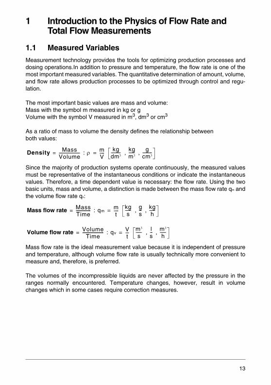
Measurement technology provides the tools for optimizing production processes anddosing operations.In addition to pressure and temperature, the flow rate is one of themost important measured variables. The quantitative determination of amount, volume,and flow rate allows production processes to be optimized through control and regu-lation.
The most important basic values are mass and volume: Mass with the symbol m measured in kg or gVolume with the symbol V measured in m3, dm3 or cm3
As a ratio of mass to volume the density defines the relationship between both values:
Since the majority of production systems operate continuously, the measured valuesmust be representative of the instantaneous conditions or indicate the instantaneousvalues. Therefore, a time dependent value is necessary: the flow rate. Using the twobasic units, mass and volume, a distinction is made between the mass flow rate qm andthe volume flow rate qv:
Mass flow rate is the ideal measurement value because it is independent of pressureand temperature, although volume flow rate is usually technically more convenient tomeasure and, therefore, is preferred.
The volumes of the incompressible liquids are never affected by the pressure in theranges normally encountered. Temperature changes, however, result in volumechanges which in some cases require correction measures.
: , ,
: , ,
: , ,
Density MassVolume-----------------------= ρ m
V-----=
kgdm3---------- kg
m3------ g
cm3----------
Mass flow rate MassTime----------------= qm
mt
-----=kgs
------ gs--- kg
h------
Volume flow rate VolumeTime
-----------------------= qvVt----=
m3
s------ l
s--- m3
h------
13
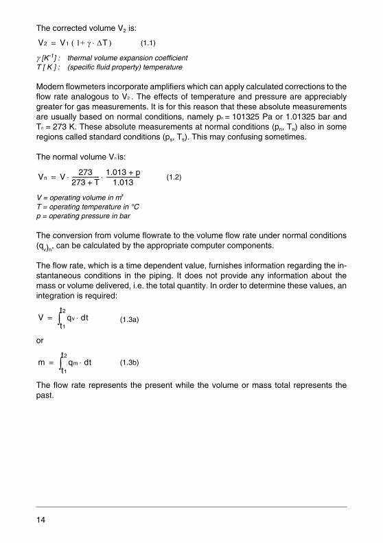
The corrected volume V2 is:
γ [K-1] : thermal volume expansion coefficientT [ K ] : (specific fluid property) temperature
Modern flowmeters incorporate amplifiers which can apply calculated corrections to theflow rate analogous to V2 . The effects of temperature and pressure are appreciablygreater for gas measurements. It is for this reason that these absolute measurementsare usually based on normal conditions, namely pn = 101325 Pa or 1.01325 bar andTn = 273 K. These absolute measurements at normal conditions (pn, Tn) also in someregions called standard conditions (ps, Ts). This may confusing sometimes.
The normal volume Vn is:
V = operating volume in m3
T = operating temperature in °C p = operating pressure in bar
The conversion from volume flowrate to the volume flow rate under normal conditions(q
v)n, can be calculated by the appropriate computer components.
The flow rate, which is a time dependent value, furnishes information regarding the in-stantaneous conditions in the piping. It does not provide any information about themass or volume delivered, i.e. the total quantity. In order to determine these values, anintegration is required:
or
The flow rate represents the present while the volume or mass total represents thepast.
(1.1)
(1.2)
(1.3a)
(1.3b)
V2 V1 ( 1+ γ ΔT )⋅=
Vn V 273273 T+-------------------- 1.013 + p
1.013-------------------------⋅ ⋅=
V qv
t1
t2
∫ dt⋅=
m qm
t1
t2
∫ dt⋅=
14
1.2 Fluid Mechanics Concepts
1.2.1 Viscosity
The viscosity of a fluid characterizes its ability to resist shape changes and is definedas its resistance to shear forces. This is a result of the internal friction in the fluid causedby the forces between the molecules. Since the molecular movement is related to thetemperature, the viscosity is also a function of the temperature. The absolute viscosityη in Pa·s (Pascal-second) is defined as follows: 1 Pascal-second is the absolute vis-cosity of the laminar flow of a homogeneous fluid between two flat parallel layersspaced 1 meter apart with a velocity difference of 1 m/s and in which a shear force of1 Pascal exists.
The kinematic viscosity ν is a density related viscosity and has units of m2/s:
This fluid property, viscosity, also exists in gases. The values are appreciably smallerthan for liquids and increase with temperature. For liquids the viscosity reduces withincreasing temperature.
1.2.2 Reynolds Number
The Reynolds Number Re is a characteristic number utilized in similarity techniques.With it, it is possible to project values measured with a particular flowing fluid to anotherfluid with different viscosity and density values, but with similar geometric relationships:
d: pipe diameter in mv: average flow velocity in m/s:ν: kinematic viscosity in m2/s
(1.4)
(1.5)
ν ηρ---= Pa s m3⋅ ⋅
kg--------------------------
m2
s-------=
Re d v⋅ν
---------- [ 1 ]=
15
1.2.3 Flow Regimes
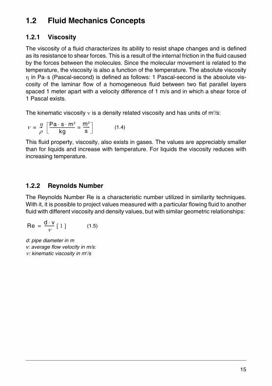
At low velocities and high viscosities the fluid flows in layers, meaning that the fluid par-ticles move in well ordered adjacent sliding layers. This is known as laminar flow inwhich the layers do not mix with one another.
Fig. 1-1: Laminar Flow Velocity Profile
The velocity distribution shows that the frictional forces at the stationary pipe wall exertthe highest retarding force and that from layer to layer the velocity increases to its max-imum value, which occurs in the middle of the pipe.
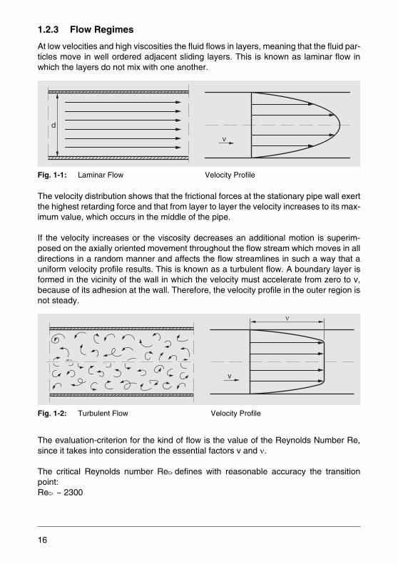
If the velocity increases or the viscosity decreases an additional motion is superim-posed on the axially oriented movement throughout the flow stream which moves in alldirections in a random manner and affects the flow streamlines in such a way that auniform velocity profile results. This is known as a turbulent flow. A boundary layer isformed in the vicinity of the wall in which the velocity must accelerate from zero to v,because of its adhesion at the wall. Therefore, the velocity profile in the outer region isnot steady.
Fig. 1-2: Turbulent Flow Velocity Profile
The evaluation-criterion for the kind of flow is the value of the Reynolds Number Re,since it takes into consideration the essential factors v and ν.
The critical Reynolds number ReCr defines with reasonable accuracy the transitionpoint:ReCr ~ 2300
v
d
v
16

Tab. 1-1: Flow Effects
Under ideal conditions the transition can occur at higher Reynolds numbers. This un-stable condition changes immediately to the stable turbulent condition at the slighteststimulus, e.g. due to a flow disturbance.
Almost all flowmeters operate at flow velocities in the turbulent range. In specific casesmay transitional flow as a mixture of laminar and turbulent flow, with e. g. turbulence inthe center of the pipe, and laminar flow near the edges appear.
1.2.4 Flow Separation
As already mentioned, there exists at the wall of the flow conduit a boundary layer inwhich the flow velocity increases from zero to v. A projecting obstruction at the wall ex-tends the length of the boundary layer and restrains the fluid even more in the vicinityof the wall so that downstream of this restriction a dead zone with a slightly negativepressure exists. The fluid flows from the region of higher velocity into this dead zoneand creates vortices.
Fig. 1-3: Dead Zone with Vortex Formation
Kind of flow Re < 2300 Re > 2300
Kind of flow laminar turbulent
Pressure drop in piping, measuring device small appreciable
Velocity profile parabolic approx. rectangular
Relationship of the average value of the flowvelocity to the maximum velocity at the center of the pipe
0.5 0.8...0.9
Vortex formation
Acceleration Restraining
17
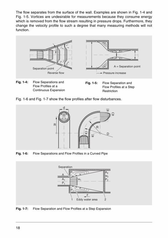
The flow separates from the surface of the wall. Examples are shown in Fig. 1-4 andFig. 1-5. Vortices are undesirable for measurements because they consume energywhich is removed from the flow stream resulting in pressure drops. Furthermore, theychange the velocity profile to such a degree that many measuring methods will notfunction.
Fig. 1-4: Flow Separations and Flow Profiles at a Continuous Expansion
Fig. 1-6 and Fig. 1-7 show the flow profiles after flow disturbances.
Fig. 1-6: Flow Separations and Flow Profiles in a Curved Pipe
Fig. 1-7: Flow Separation and Flow Profiles at a Step Expansion
Separation point
Reverse flow
A = Separation point
Pressure increase
Fig. 1-5: Flow Separation and Flow Profiles at a StepRestriction
RR
Dw
w
w
wd
A
A1 w1P1
P1
P1
A2w2P2
1 2
Separation
Eddy water area
F
18
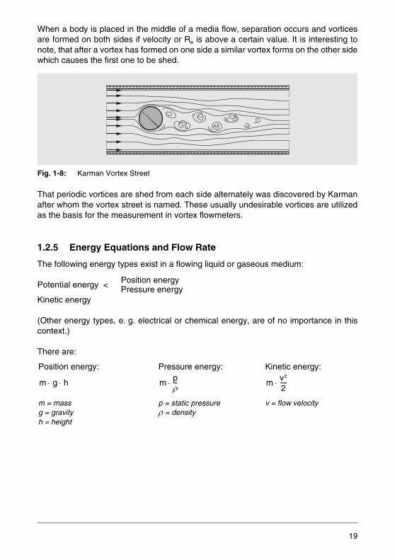
When a body is placed in the middle of a media flow, separation occurs and vorticesare formed on both sides if velocity or Re is above a certain value. It is interesting tonote, that after a vortex has formed on one side a similar vortex forms on the other sidewhich causes the first one to be shed.
Fig. 1-8: Karman Vortex Street
That periodic vortices are shed from each side alternately was discovered by Karmanafter whom the vortex street is named. These usually undesirable vortices are utilizedas the basis for the measurement in vortex flowmeters.
1.2.5 Energy Equations and Flow Rate
The following energy types exist in a flowing liquid or gaseous medium:
Position energy Potential energy < Pressure energyKinetic energy
(Other energy types, e. g. electrical or chemical energy, are of no importance in thiscontext.)
There are:
Position energy:
m = massg = gravityh = height
Pressure energy:
p = static pressure ρ = density
Kinetic energy:
v = flow velocity
m g h⋅ ⋅ m pρ---⋅ m v2
2-----⋅
19

Their sum is:
The Bernoulli law of conservation of energy states that the sum of the energy at everylocation in the flow passage must remain constant (expansion must be considered forcompressible gases), when energy is neither externally added nor removed. Based onthe mass flow q
m this yields:
This equation can be simplified because there are only minor position changes in a pip-ing so that the potential energy can be neglected:
Or, when comparing two reference points (Fig. 1-9):
Fig. 1-9: Piping Expansion
Rearranging equation (1.9), the basic equation for the pressure drop becomes:
(1.6)
(1.7)
(1.8)
(1.9)
(1.10)
E m g h m pρ--- m v2
2-----⋅+⋅+⋅ ⋅=
g h pρ---
v2
2-----= constant+ +⋅
pρ---
v2
2----- = constant+
p1
ρ----- v12
2------- p2
ρ----- v22
2-------+=+
p1
p2
v1 v2
Δp p1 p2 ρ2--- v22 v12–( )=–=
20
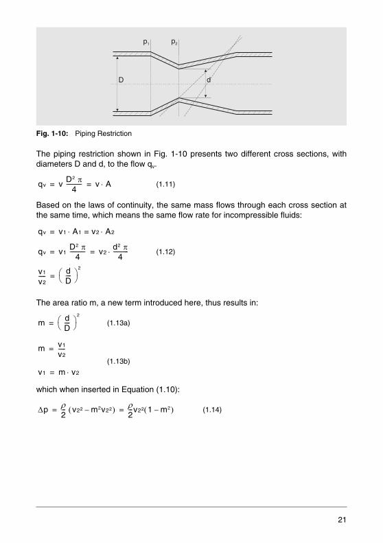
Fig. 1-10: Piping Restriction
The piping restriction shown in Fig. 1-10 presents two different cross sections, withdiameters D and d, to the flow qv.
Based on the laws of continuity, the same mass flows through each cross section atthe same time, which means the same flow rate for incompressible fluids:
The area ratio m, a new term introduced here, thus results in:
which when inserted in Equation (1.10):
(1.11)
(1.12)
(1.13a)
(1.13b)
(1.14)
p1 p2
D d
qv v D2 π4
----------- v A⋅= =
qv v1 A1 v2 A2⋅=⋅=
qv v1 D2 π4
----------- v2d2 π
4-----------⋅= =
v1
v2----- d
D---- ⎝ ⎠
⎛ ⎞2
=
m dD---- ⎝ ⎠
⎛ ⎞2
=
m v1
v2-----=
v1 m v2⋅=
Δp ρ2--- v22 m2v22–( ) ρ
2---v22 1 m2–( )= =
21
Replacing v2 with:
From this results the flow rate:
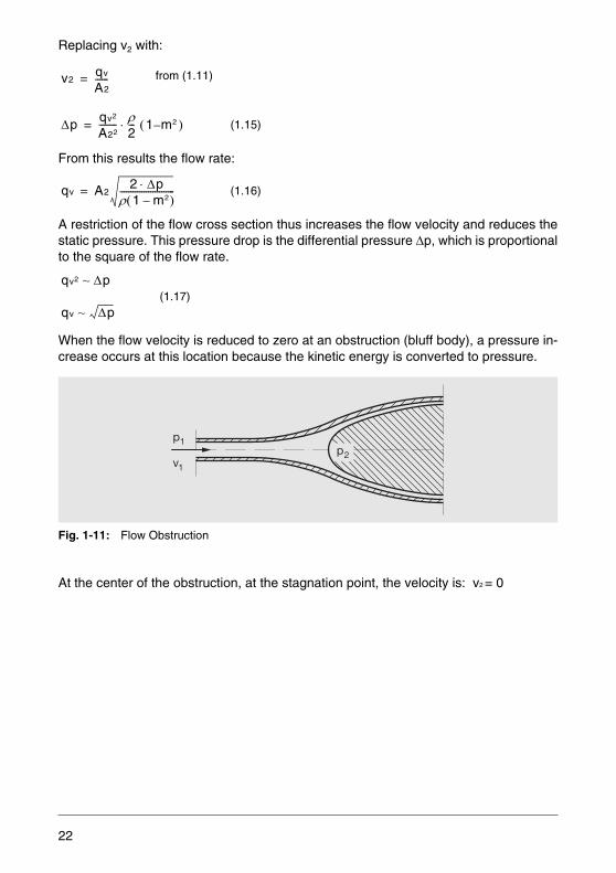
A restriction of the flow cross section thus increases the flow velocity and reduces thestatic pressure. This pressure drop is the differential pressure Δp, which is proportionalto the square of the flow rate.
When the flow velocity is reduced to zero at an obstruction (bluff body), a pressure in-crease occurs at this location because the kinetic energy is converted to pressure.
Fig. 1-11: Flow Obstruction
At the center of the obstruction, at the stagnation point, the velocity is: v2 = 0
from (1.11)
(1.15)
(1.16)
(1.17)
v2qv
A2------=
Δp qv2
A22-------- ρ
2--- 1 m2 )–(⋅=
qv A22 Δp⋅
ρ 1 m2–( )-------------------------=
qv2 ~ Δp
qv ~ Δp
p2
p1
v1
22
It follows from Equation (1.9):
The total pressure p2 at the stagnation point is thus the total of the static pressure p1 andthe converted dynamic pressure:
Pdyn = .
Therefore, if both of these pressure values are known, then the flow velocity and thusthe pressure can be calculated from:
This relationship is used to determine the flow velocity for stagnation pressure mea-surements.
1.2.6 Channel Hydraulics
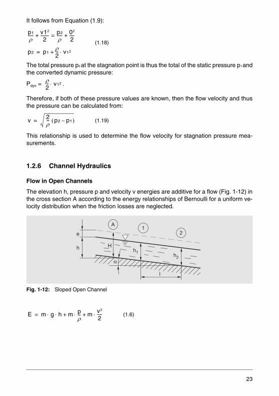
Flow in Open Channels
The elevation h, pressure p and velocity v energies are additive for a flow (Fig. 1-12) inthe cross section A according to the energy relationships of Bernoulli for a uniform ve-locity distribution when the friction losses are neglected.
Fig. 1-12: Sloped Open Channel
(1.18)
(1.19)
(1.6)
p1
ρ----- v12
2-------- p2
ρ----- 02
2-----+=+
p2 p1ρ2--- v12⋅+=
ρ2--- v12⋅
v 2ρ--- p2 p1–( )=
A1
2
h1h2
H
l
α
e
h
E m g h m pρ--- m v2
2-----⋅+⋅+⋅ ⋅=
23
Neglecting the atmospheric pressure which is constant and does not influence this dis-cussion and expressing the energy values as fluid heights the equation can be writtenas:
The expression:
e =
symbolizes the conversion of the kinetic energy into potential energy expressed as afluid elevation. The curve e is the energy line.
Based on the laws of continuity, the energy contents at points 1 and 2 must be thesame:
To investigate the flow conditions for different slopes, the elevation difference is includ-ed:
After simplification and algebraic rearrangement, the expression for the slope of the up-per water surface for rectangular cross sections is:
Substituting v = a noteworthy limiting velocity vlim is reached, the wave propaga-tion velocity. It is identical to the propagation velocity of flat waves. In Equation 1.23 atvlim, the term is:
(1.20)
(1.21)
(1.22a)
(1.22b)
(1.23)
H h v2
2g------- h e+=+=
v2
2g-------
h1v12
2g------- h2
v22
2g-------+=+
h1 l αtan v12
2g------- h2
v22
2g-------+=+⋅+
h2 h1v12 v22–
2g--------------------- l αtan⋅=––
h2 h1–l
----------------- αtan
1 v2
g h⋅-----------–
--------------------≈
g h⋅
1 v2
g h⋅----------- 0=–
24
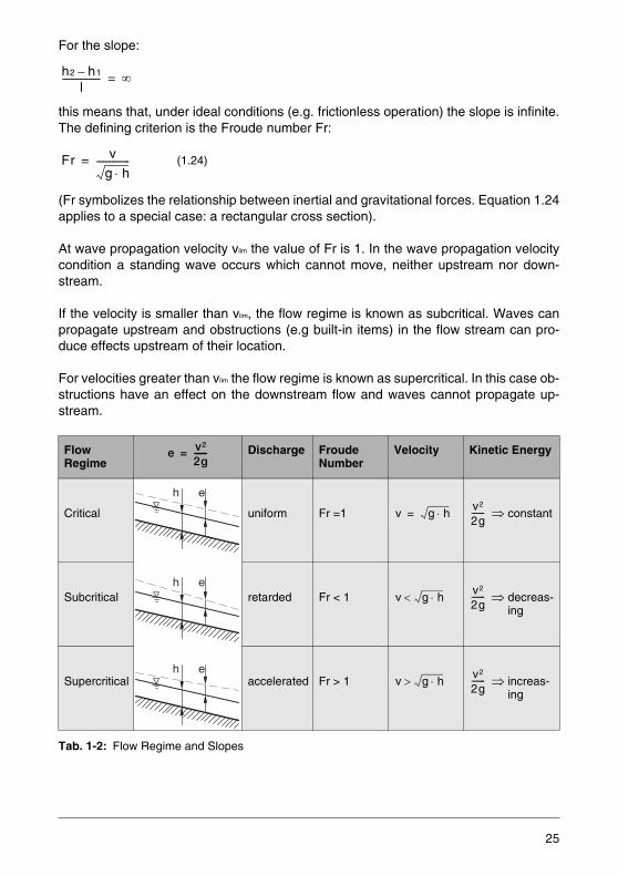
For the slope:
this means that, under ideal conditions (e.g. frictionless operation) the slope is infinite.The defining criterion is the Froude number Fr:
(Fr symbolizes the relationship between inertial and gravitational forces. Equation 1.24applies to a special case: a rectangular cross section).
At wave propagation velocity vlim the value of Fr is 1. In the wave propagation velocitycondition a standing wave occurs which cannot move, neither upstream nor down-stream.
If the velocity is smaller than vlim, the flow regime is known as subcritical. Waves canpropagate upstream and obstructions (e.g built-in items) in the flow stream can pro-duce effects upstream of their location.
For velocities greater than vlim the flow regime is known as supercritical. In this case ob-structions have an effect on the downstream flow and waves cannot propagate up-stream.
Tab. 1-2: Flow Regime and Slopes
(1.24)
Flow Regime
Discharge Froude Number
Velocity Kinetic Energy
Critical uniform Fr =1 ⇒ constant
Subcritical retarded Fr < 1 ⇒ decreas- ing
Supercritical accelerated Fr > 1 ⇒ increas- ing
h2 h1–l
----------------- ∞=
Fr v
g h⋅---------------=
e v2
2g-----=
eh
eh
eh
v g h⋅=v2
2g------
v g h⋅< v2
2g------
v g h⋅> v2
2g------
25
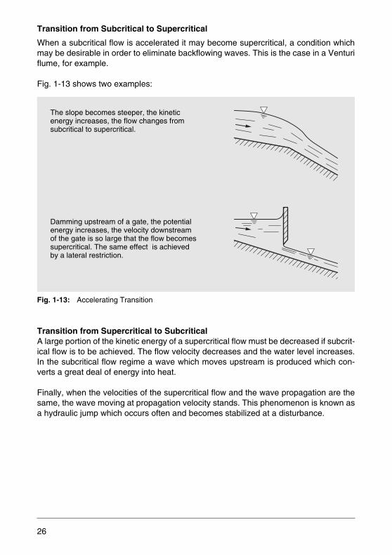
Transition from Subcritical to Supercritical
When a subcritical flow is accelerated it may become supercritical, a condition whichmay be desirable in order to eliminate backflowing waves. This is the case in a Venturiflume, for example.
Fig. 1-13 shows two examples:
Fig. 1-13: Accelerating Transition
Transition from Supercritical to SubcriticalA large portion of the kinetic energy of a supercritical flow must be decreased if subcrit-ical flow is to be achieved. The flow velocity decreases and the water level increases.In the subcritical flow regime a wave which moves upstream is produced which con-verts a great deal of energy into heat.
Finally, when the velocities of the supercritical flow and the wave propagation are thesame, the wave moving at propagation velocity stands. This phenomenon is known asa hydraulic jump which occurs often and becomes stabilized at a disturbance.
The slope becomes steeper, the kinetic energy increases, the flow changes from subcritical to supercritical.
Damming upstream of a gate, the potential energy increases, the velocity downstream of the gate is so large that the flow becomes supercritical. The same effect is achieved by a lateral restriction.
26
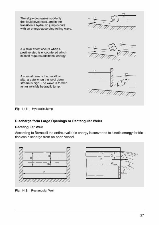
Fig. 1-14: Hydraulic Jump
Discharge form Large Openings or Rectangular Weirs
Rectangular Weir
According to Bernoulli the entire available energy is converted to kinetic energy for fric-tionless discharge from an open vessel.
Fig. 1-15: Rectangular Weir
The slope decreases suddenly, the liquid level rises, and in the transition a hydraulic jump occurs with an energy-absorbing rolling wave.
A similar effect occurs when apositive step is encountered which in itself requires additional energy.
A special case is the backflowafter a gate when the level down-stream is high. The wave is formedas an invisible hydraulic jump.
b
x
dx Vmax.
VxX
hh
27
At a depth x there is the discharge velocity:
Through the area Ax = b · dx the flow qvx = Ax · vx comes out:
The following is valid for the entire opening:
Losses actually occur in the discharge which are incorporated in the discharge coeffi-cient μ:
This equation forms the basis of the measurement calculation for meter tubes and mea-suring channels.
(1.25)
(1.26a)
(1.26b)
(1.27)
vx 2g x⋅=
qvx b dx 2g x⋅⋅ ⋅=
qv b
0
h
∫ 2g x⋅ dx⋅=
qv23--- b h 2g h⋅⋅ ⋅ ⋅=
qv23--- b 2g h3 2/⋅ ⋅ ⋅=
qv23--- μ b 2g h3 2/⋅ ⋅ ⋅=
28
2 Flow Rate and Total Flow Measurement of Gases and Liquids
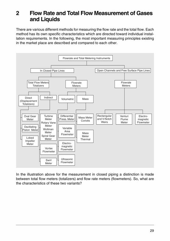
There are various different methods for measuring the flow rate and the total flow. Eachmethod has its own specific characteristics which are directed toward individual instal-lation requirements. In the following, the most important measuring principles existingin the market place are described and compared to each other.
In the illustration above for the measurement in closed piping a distinction is madebetween total flow meters (totalizers) and flow rate meters (flowmeters). So, what arethe characteristics of these two variants?
UltrasonicFlowmeter
Direct(Displacement
Totalizers)
Total Flow MetersTotalizers
Indirect
Oval GearMeter
OscillatingPiston Meter
LobedImpellerMeter
VortexFlowmeter
SwirlMeter
TurbineMeter
Rotary VaneMeter
WoltmanMeter
Spiral GearMeter
MassVolumetric
FlowrateMeters
In Closed Pipe Lines Open Channels and Free Surface Pipe Lines
Flowrate and Total Metering Instruments
FlowrateMeters
DifferentialPress. Meter
VariableArea
Flowmeter
Electro-magnetic
Flowmeter
Rectangularand V-Notch
Weirs
Electro-magnetic
Flowmeter
VenturiFlumeMeter
Mass MeterCoriolis
MassMeter
Thermal
29
Total flow meters, usually volume totalizers, are devices filled with a defined volumewhich is then measured and integrated to determine the total flow volume. Direct vol-ume totalizers have movable measuring chambers with a defined volume (comparableto a line of buckets). Indirect volume totalizers, on the contrary, do not have closedmeasuring chambers, but work either mechanically using rotary vanes and transportingpartial volumes between the vanes, or electrically with pulses that are proportional tothe volume.
Flowmeters also use the direct method for measured value acquisition. They measureeither the flow velocity or the kinetic energy of the flow.
The user faces the difficult task of selecting the technically best and most cost effectivemeasuring device for his application. The following device descriptions and selectioncriteria are intended to assist in that choice.
2.1 Volume Totalizers
Volume totalizers with moving measuring chambers driven by the measuring mediumare also known as displacement meters. They are suitable for both gases and liquids.They are direct volume totalizers since they transport the measuring medium in cham-bers with defined, geometrically limited volumes.
Among the direct volume totalizers are those with measuring vanes – also called tur-bine totalizers – and volume totalizers with forced flow changes. In this method a pulsetotal is generated which represents a specific – not geometrically bounded – volume,for example the quantity which produces one complete revolution of a rotary vane to-talizer.
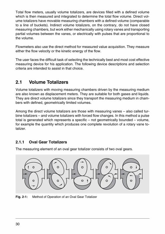
2.1.1 Oval Gear Totalizers
The measuring element of an oval gear totalizer consists of two oval gears.
Fig. 2-1: Method of Operation of an Oval Gear Totalizer
30
The driving liquid produces the required torque, which varies as a function of the gearposition, to rotate the gears.
For example, the torques on the lower gear in the left side of Fig. 2-1 cancel each otherwhile the torque on the upper gear is one sided and actually causes the rotation.Around the upper gear a bounded crescent like volume exists which is pushed towardsthe outlet of the meter. Each rotation of the pair of oval gears transports a defined liquidvolume.
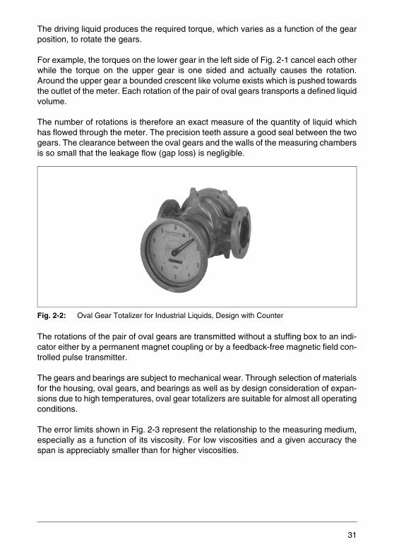
The number of rotations is therefore an exact measure of the quantity of liquid whichhas flowed through the meter. The precision teeth assure a good seal between the twogears. The clearance between the oval gears and the walls of the measuring chambersis so small that the leakage flow (gap loss) is negligible.
Fig. 2-2: Oval Gear Totalizer for Industrial Liquids, Design with Counter
The rotations of the pair of oval gears are transmitted without a stuffing box to an indi-cator either by a permanent magnet coupling or by a feedback-free magnetic field con-trolled pulse transmitter.
The gears and bearings are subject to mechanical wear. Through selection of materialsfor the housing, oval gears, and bearings as well as by design consideration of expan-sions due to high temperatures, oval gear totalizers are suitable for almost all operatingconditions.
The error limits shown in Fig. 2-3 represent the relationship to the measuring medium,especially as a function of its viscosity. For low viscosities and a given accuracy thespan is appreciably smaller than for higher viscosities.
31
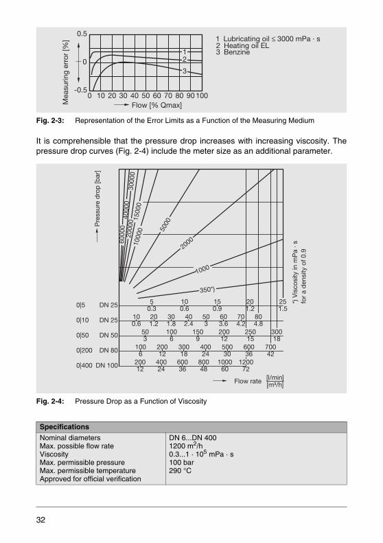
Fig. 2-3: Representation of the Error Limits as a Function of the Measuring Medium
It is comprehensible that the pressure drop increases with increasing viscosity. Thepressure drop curves (Fig. 2-4) include the meter size as an additional parameter.
Fig. 2-4: Pressure Drop as a Function of Viscosity
Specifications
Nominal diametersMax. possible flow rateViscosityMax. permissible pressureMax. permissible temperatureApproved for official verification
DN 6...DN 4001200 m2/h0.3...1 · 105 mPa · s100 bar290 °C
0
0
10
3
21
20 30 40 50 60 70 80 90 100
2 Heating oil EL3 Benzine
1 Lubricating oil 3000 mPa s≤ ·
Flow [% Qmax]Mea
surin
g er
ror
[%]
-0.5
0.5
1000
350*)
2000
5000
1000
015
000
2000
060
000
4000
030
000
[l/min][m³/h]Flow rate
Pre
ssur
e d
rop
[bar
]
*)V
isco
sity
in m
Pa
s·fo
r a
den
sity
of 0
.9DN 25 5
0.3100.6
150.9
201.2
251.5
201.2
100.6
503
1006
20012
40024
60036
80048
100060
120072
20012
30018
40024
50030
60036
70042
1006
1509
20012
25015
30018
301.8
402.4
503
603.6
704.2
804.8DN 25
DN 50
DN 100
DN 80
0|5
0|10
0|50
0|200
0|400
32
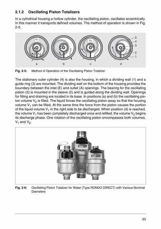
2.1.2 Oscillating Piston Totalizers
In a cylindrical housing a hollow cylinder, the oscillating piston, oscillates eccentrically.In this manner it transports defined volumes. The method of operation is shown in Fig.2-5.
Fig. 2-5: Method of Operation of the Oscillating Piston Totalizer
The stationary outer cylinder (4) is also the housing, in which a dividing wall (1) and aguide ring (3) are mounted. The dividing wall on the bottom of the housing provides theboundary between the inlet (E) and outlet (A) openings. The bearing for the oscillatingpiston (5) is mounted in the sleeve (2) and is guided along the dividing wall. Openingsfor filling and draining are located in its base. In positions (a) and (b) the oscillating pis-ton volume V2 is filled. The liquid forces the oscillating piston away so that the housingvolume V1 can be filled. At the same time the force from the piston causes the portionof the liquid volume V1 in the right side to be discharged. When position (d) is reached,the volume V1 has been completely discharged once and refilled, the volume V2 beginsits discharge phase. One rotation of the oscillating piston encompasses both volumes,V1 and V2.
Fig. 2-6: Oscillating Piston Totalizer for Water (Type RONDO DIRECT) with Various Nominal Diameters
E A
V2V1
543
21
a b c d
33

The movement of the piston bearing (2) is transmitted to an indicator using a magnetand follower arrangement. A magnetic coupling is not utilized in the RONDO DIRECTOscillating Piston Totalizer. The rotary motion of the piston is transmitted directly fromthe piston to the totalizer.
Since the oscillating piston wears rapidly, proper material selection is very important.Various materials are available such as gray cast iron, bronze, hard rubber, carbon andplastics. For high temperature operation an intermediate spacer is used to provide ad-ditional separation from the totalizer. Oscillating piston totalizers are especially used forwater and oil measurement.
Fig. 2-7: Representation of the Measuring Error as a Function of the Viscosity
The error curves in Fig. 2-7 indicate the high accuracy attainable at high viscosity dueto a decrease in leakage losses (gap losses). The oscillating piston totalizers are stilloperational at viscosities as high as 10,000 mPa·s.
Meas. range 1:5(for liquefied gas)
Measuring range 1:10
Flow rate [Qmax]
12
43
5
2 5mPa · s
4 0.5mPa · s5 0.25mPa · s
3 1mPa · s
1 100mPa · s
Mea
surin
g er
ror
[%]
-0.5
0.5
0
0 10 25 50 75 100
34
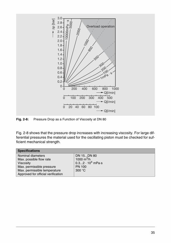
Fig. 2-8: Pressure Drop as a Function of Viscosity at DN 80
Fig. 2-8 shows that the pressure drop increases with increasing viscosity. For large dif-ferential pressures the material used for the oscillating piston must be checked for suf-ficient mechanical strength.
Specifications
Nominal diametersMax. possible flow rateViscosityMax. permissible pressureMax. permissible temperatureApproved for official verification
DN 15...DN 801000 m3/h0.3...2 · 104 mPa·sPN 100300 °C
1000
0mP
a· s
5000
2000
1000
800
300
200
100
1mPa · s
500
0
0 100 200 300 400 500
0 20 40 60 80 100
200 400 600 800 1000
Overload operation
00.20.40.60.81.01.21.41.61.82.02.22.42.62.83.0
Q[l/min]
Q[l/min]
Q[l/min]
35

2.1.3 Lobed Impeller Gas Totalizers
Two rotating impellers, designed with a figure eight cross section, rotate in opposite di-rections due to the forces exerted by the gas being measured. The shape of the impel-lers prevents contact while the gap between them remains constant.
Fig. 2-9: Method of Operation of the Lobed Impeller Gas Totalizer
A gear drive external to the measuring chamber synchronizes the impellers. Duringeach rotation four crescent shaped volumes are moved through the measuring cham-ber. The number of rotations is proportional to the gas flow. The rotation is coupled us-ing an adjustable fine tooth gear train to the totalizer.
Fig. 2-10: Lobed Impeller Gas Totalizer
An unmeasured flow, which is a function of the pressure drop, flows through the gaps.The negative error is compensated by an adjustment. The viscosity of gases increasesat high pressures and reduces the losses in the gaps which compensates for the higherlosses which would otherwise exist due to the higher pressure difference.
36
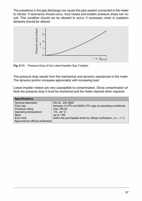
The pulsations in the gas discharge can cause the pipe system connected to the meterto vibrate. If resonance should occur, loud noises and sudden pressure drops can re-sult. This condition should not be allowed to occur; if necessary noise or pulsationdampers should be utilized.
Fig. 2-11: Pressure Drop of the Lobed Impeller Gas Totalizer
The pressure drop results from the mechanical and dynamic resistances in the meter.The dynamic portion increases appreciably with increasing load.
Lobed impeller meters are very susceptible to contamination. Since contamination af-fects the pressure drop it must be monitored and the meter cleaned when required.
Specifications
Nominal diametersFlow ratePressure ratingOperating temperatureSpanError limitApproved for official verification
DN 40...DN 3000between 3 m3/h and 6500 m3/h (gas at operating conditions)max. PN 25-10...40 °Cup to 1:50within the permissible limits for official verification, i.e. < 1 %
Pre
ssur
e d
rop
[mb
ar]
0
1
2
3
[Qmax]
37

2.1.4 Turbine Totalizers
Turbine totalizers are indirect volume totalizers in which the flow causes a vaned rotorto revolve. The number of rotor revolutions is proportional to the total flow and the fre-quency of the revolutions to the flow rate.
The various designs are differentiated by the direction of the inflow and by the methodutilized for measured value acquisition.
Rotary Vane Totalizer
The flow entry is tangential and causes the wheel to revolve in the rotary vane totalizer.A gear train is utilized to transmit the rotations of the wheel axle to the totalizer which,in wetted designs, is located in the measuring medium. Rotary vane totalizers are avail-able as single jet (Fig. 2-12a) and as multijet designs (Fig. 2-12b).
Fig. 2-12: Rotary Vane Totalizer
Dry design units separate the indicator chamber from the measuring chamber andtransmit the rotation via a magnetic coupling. Rotary vane totalizers are used as do-mestic water meters and also, in hot water design, as volume measuring elements forsmaller heat quantity totalizers.
Fig. 2-13: Error Curve of a Multijet Rotary Vane Totalizer
a b
5
0
-51 3 10 100
low
er li
mit
Mea
surin
g ra
nge
Ran
gese
par
atio
n
Upper measuring range
Nom
inal
rat
ing
Lowermeasuring range
Flow rate [%]
Mea
surin
ger
ror
[%]
0.4
38

Fig. 2-13 shows the error curve with reference to the limits specified in the German Ver-ification Act, i.e. ± 2 % (cold water)/ ± 3 % (warm water) in the upper and lower mea-suring range.
Fig. 2-14: Cross Section of a Single Jet Totalizer (Type PICOFLUX)
Fig. 2-15: Cross Section of a Multijet Totalizer (Type OPTIMA ARTIST)
SpecificationsNominal sizes (based on the flow rate)Smallest possible flow rateLargest possible flow rateViscosity limitApproved for official verification
0.6...15 m3/h12 l/h30 m3/h≤ 5 mPa·s
39
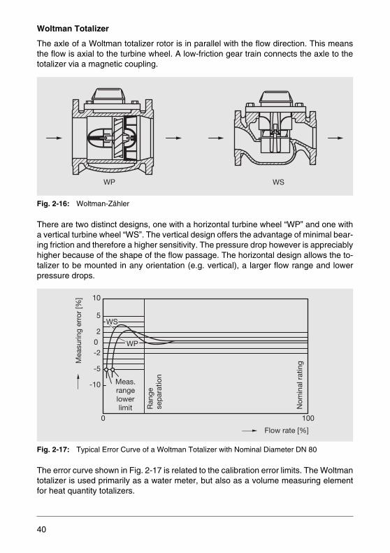
Woltman Totalizer
The axle of a Woltman totalizer rotor is in parallel with the flow direction. This meansthe flow is axial to the turbine wheel. A low-friction gear train connects the axle to thetotalizer via a magnetic coupling.
Fig. 2-16: Woltman-Zähler
There are two distinct designs, one with a horizontal turbine wheel “WP” and one witha vertical turbine wheel “WS”. The vertical design offers the advantage of minimal bear-ing friction and therefore a higher sensitivity. The pressure drop however is appreciablyhigher because of the shape of the flow passage. The horizontal design allows the to-talizer to be mounted in any orientation (e.g. vertical), a larger flow range and lowerpressure drops.
Fig. 2-17: Typical Error Curve of a Woltman Totalizer with Nominal Diameter DN 80
The error curve shown in Fig. 2-17 is related to the calibration error limits. The Woltmantotalizer is used primarily as a water meter, but also as a volume measuring elementfor heat quantity totalizers.
WP WS
WP
WS
-10
-5
-202
5
10
0 100
Nom
inal
rat
ing
Meas.rangelowerlimit R
ange
sep
arat
ion
Mea
surin
g er
ror
[%]
Flow rate [%]
40
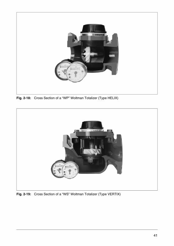
Fig. 2-18: Cross Section of a “WP” Woltman Totalizer (Type HELIX)
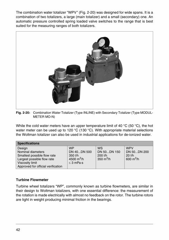
Fig. 2-19: Cross Section of a “WS” Woltman Totalizer (Type VERTIX)
41
The combination water totalizer “WPV” (Fig. 2-20) was designed for wide spans. It is acombination of two totalizers, a large (main totalizer) and a small (secondary) one. Anautomatic pressure controlled spring loaded valve switches to the range that is bestsuited for the measuring ranges of both totalizers.
Fig. 2-20: Combination Water Totalizer (Type INLINE) with Secondary Totalizer (Type MODUL-METER MO-N)
While the cold water meters have an upper temperature limit of 40 °C (50 °C), the hotwater meter can be used up to 120 °C (130 °C). With appropriate material selectionsthe Woltman totalizer can also be used in industrial applications for de-ionized water.
Turbine Flowmeter
Turbine wheel totalizers “WP”, commonly known as turbine flowmeters, are similar intheir design to Woltman totalizers, with one essential difference: the measurement ofthe rotation is made electrically with almost no feedback on the rotor. The turbine rotorsare light in weight producing minimal friction in the bearings.
Specifications
DesignNominal diametersSmallest possible flow rateLargest possible flow rateViscosity limitApproved for official verification
WPDN 40...DN 500350 l/h4500 m3/h≤ 3 mPa·s
WSDN 50...DN 150200 l/h350 m3/h
WPVDN 50...DN 20020 l/h600 m3/h
42
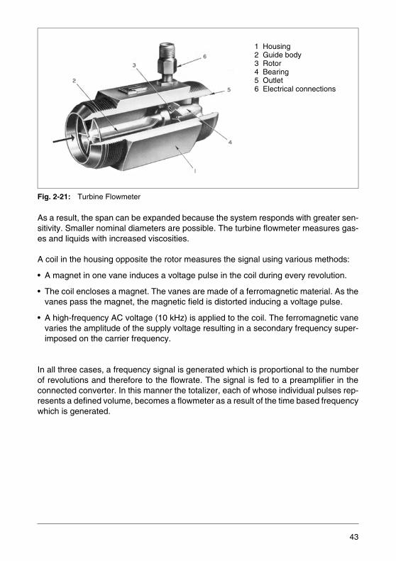
Fig. 2-21: Turbine Flowmeter
As a result, the span can be expanded because the system responds with greater sen-sitivity. Smaller nominal diameters are possible. The turbine flowmeter measures gas-es and liquids with increased viscosities.
A coil in the housing opposite the rotor measures the signal using various methods:
• A magnet in one vane induces a voltage pulse in the coil during every revolution.
• The coil encloses a magnet. The vanes are made of a ferromagnetic material. As thevanes pass the magnet, the magnetic field is distorted inducing a voltage pulse.
• A high-frequency AC voltage (10 kHz) is applied to the coil. The ferromagnetic vanevaries the amplitude of the supply voltage resulting in a secondary frequency super-imposed on the carrier frequency.
In all three cases, a frequency signal is generated which is proportional to the numberof revolutions and therefore to the flowrate. The signal is fed to a preamplifier in theconnected converter. In this manner the totalizer, each of whose individual pulses rep-resents a defined volume, becomes a flowmeter as a result of the time based frequencywhich is generated.
1 Housing2 Guide body3 Rotor4 Bearing5 Outlet6 Electrical connections
43
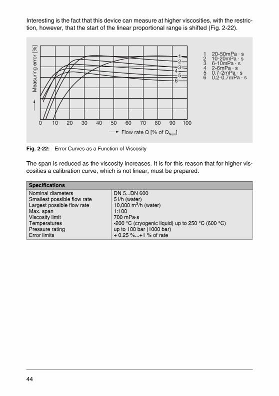
Interesting is the fact that this device can measure at higher viscosities, with the restric-tion, however, that the start of the linear proportional range is shifted (Fig. 2-22).
Fig. 2-22: Error Curves as a Function of Viscosity
The span is reduced as the viscosity increases. It is for this reason that for higher vis-cosities a calibration curve, which is not linear, must be prepared.
Specifications
Nominal diametersSmallest possible flow rateLargest possible flow rateMax. spanViscosity limitTemperaturesPressure ratingError limits
DN 5...DN 6005 l/h (water)10,000 m3/h (water)1:100700 mPa·s-200 °C (cryogenic liquid) up to 250 °C (600 °C)up to 100 bar (1000 bar)+ 0.25 %...+1 % of rate
0 10 20 30 40 50 60 70 80 90 100
123
45
6
Mea
surin
g er
ror
[%]
Flow rate Q [% of Q ]Nom
2 10-20mPa · s
4 2-6mPa · s
6 0.2-0.7mPa · s5 0.7-2mPa · s
3 6-10mPa · s
1 20-50mPa · s
44

A special turbine flowmeter variation is the turbine gas totalizer for measuring large gasflows. The gas flow velocity is increased by a reducer at the inlet with a ring shapedcross section and guided over the freely turning rotor. The revolutions which are mea-sured are mechanically transmitted to the totalizer using a gear train.
This instrument is often used for the custody transfer of natural gas for which it has re-ceived certification approval.
2.1.5 Vortex Flowmeters
Why does the flag flap in the breeze? Why does a taut line (power line) sing in the wind?There are numerous examples of the effects of vortex formation at bodies around whichthere is flow. What is actually happening?
As already mentioned in Chapter 1.2.4 a flow obstruction causes vortices. On a freestanding body vortices are formed on both sides which are alternately shed resulting inthe formation of a Karman Vortex Street. The flag mentioned above reacts to theprogress of the vortex street, the taut wire vibrates at the vortex shedding frequency.
Fig. 2-23: Measuring Principle of a Vortex Flowmeter
Specifications
Nominal diametersSmallest possible flow rateLargest possible flow rateSpanCalibration error limitsTemperature limits
DN 50...DN 6002.5 m3/h (at operating conditions)25,000 m3/h1:20+1 % of rate (span 1:5)-10...50 °C
1 2
1 Bluff body2 Piezo-sensor
45
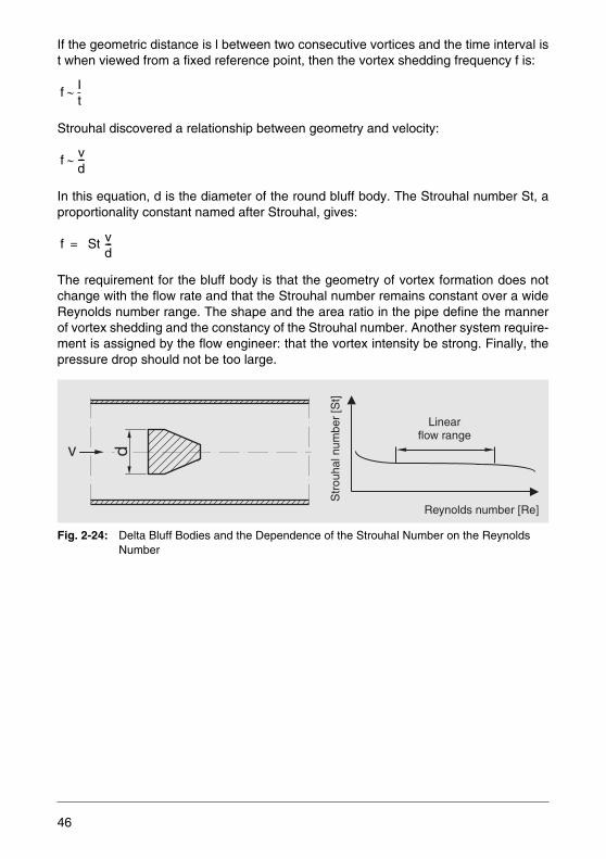
If the geometric distance is l between two consecutive vortices and the time interval ist when viewed from a fixed reference point, then the vortex shedding frequency f is:
Strouhal discovered a relationship between geometry and velocity:
In this equation, d is the diameter of the round bluff body. The Strouhal number St, aproportionality constant named after Strouhal, gives:
The requirement for the bluff body is that the geometry of vortex formation does notchange with the flow rate and that the Strouhal number remains constant over a wideReynolds number range. The shape and the area ratio in the pipe define the mannerof vortex shedding and the constancy of the Strouhal number. Another system require-ment is assigned by the flow engineer: that the vortex intensity be strong. Finally, thepressure drop should not be too large.
Fig. 2-24: Delta Bluff Bodies and the Dependence of the Strouhal Number on the Reynolds Number
f It-∼
f vd---∼
f St vd---=
Str
ouha
l num
ber
[St]
Reynolds number [Re]
Linearflow range
dv
46
The optimum shape of the bluff body has been determined empirically and through cal-culations. ABB has selected the delta shape.
The minimum Reynolds number value Remin defines the lower range value, i.e. the spandecreases with increasing viscosity. The upper Re limit is so high that it is negligible forthe upper range value.
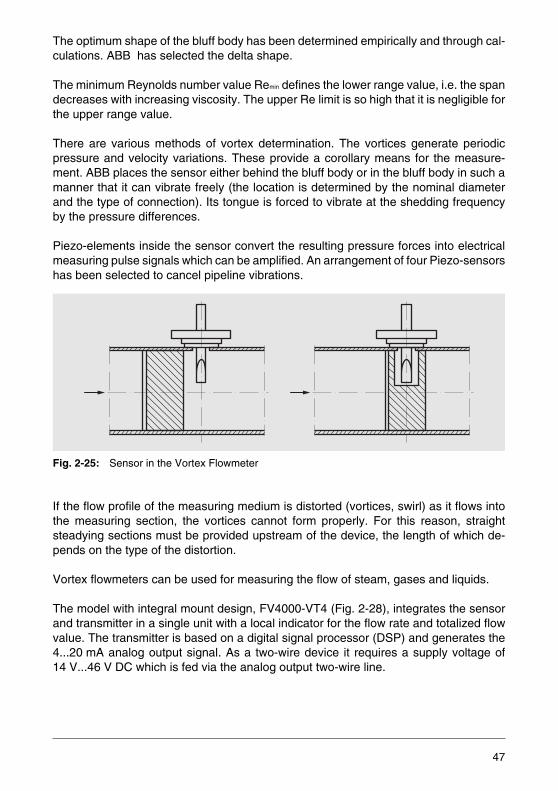
There are various methods of vortex determination. The vortices generate periodicpressure and velocity variations. These provide a corollary means for the measure-ment. ABB places the sensor either behind the bluff body or in the bluff body in such amanner that it can vibrate freely (the location is determined by the nominal diameterand the type of connection). Its tongue is forced to vibrate at the shedding frequencyby the pressure differences.
Piezo-elements inside the sensor convert the resulting pressure forces into electricalmeasuring pulse signals which can be amplified. An arrangement of four Piezo-sensorshas been selected to cancel pipeline vibrations.
Fig. 2-25: Sensor in the Vortex Flowmeter
If the flow profile of the measuring medium is distorted (vortices, swirl) as it flows intothe measuring section, the vortices cannot form properly. For this reason, straightsteadying sections must be provided upstream of the device, the length of which de-pends on the type of the distortion.
Vortex flowmeters can be used for measuring the flow of steam, gases and liquids.
The model with integral mount design, FV4000-VT4 (Fig. 2-28), integrates the sensorand transmitter in a single unit with a local indicator for the flow rate and totalized flowvalue. The transmitter is based on a digital signal processor (DSP) and generates the4...20 mA analog output signal. As a two-wire device it requires a supply voltage of14 V...46 V DC which is fed via the analog output two-wire line.
47
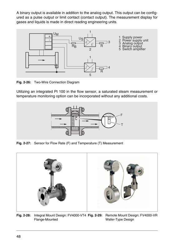
A binary output is available in addition to the analog output. This output can be config-ured as a pulse output or limit contact (contact output). The measurement display forgases and liquids is made in direct reading engineering units.
Fig. 2-26: Two-Wire Connection Diagram
Utilizing an integrated Pt 100 in the flow sensor, a saturated steam measurement ortemperature monitoring option can be incorporated without any additional costs.
Fig. 2-27: Sensor for Flow Rate (F) and Temperature (T) Measurement
Fig. 2-28: Integral Mount Design: FV4000-VT4Flange-Mounted
+UM
US
RB R
1
3
4
1
2
5R
- 2 Power supply unit
4 Binary output5 Switch amplifier
3 Analog output
1 Supply power
F
T
Fig. 2-29: Remote Mount Design: FV4000-VRWafer-Type Design
48
The transmitter can also be mounted remotely at a distance from the sensor if a specialcable (Fig. 2-29) is used. It can be attached to the wall or installed using a pipe mount-ing toolkit.
Two-Wire Design with Fieldbus Interface
The transmitter is designed in two-wire technology, i.e. the power supply and the digitalcommunication of the fieldbus interface utilize the same cable. In parallel, a switch out-put is available for limit value or system monitoring. In the event of a power failure allstored data are saved in a nonvolatile memory.
The Asset Vision Basic device management tool can be used for operating and config-uring intelligent field instruments, utilizing the FDT/DTM technology. A data exchangewith a complete range of field instruments can be accomplished over various commu-nication paths. The main operational purposes are the parameter display, configura-tion, diagnostics and data management for all intelligent field devices which them-selves satisfy the communication requirements.
PROFIBUS PA CommunicationThe transmitter is suited for connection to a DP/PA segment coupler.
PROFIBUS PA Protocol
Function blocks: 2 x Al, 1 x TOT GSD files: -PA139700 (1 x Al) (device data files) -PA139740 (1 x AI, 1 x TOT)
-ABB_05DC (2 x Al, 1 x TOT + manufacturer-specific data)
49
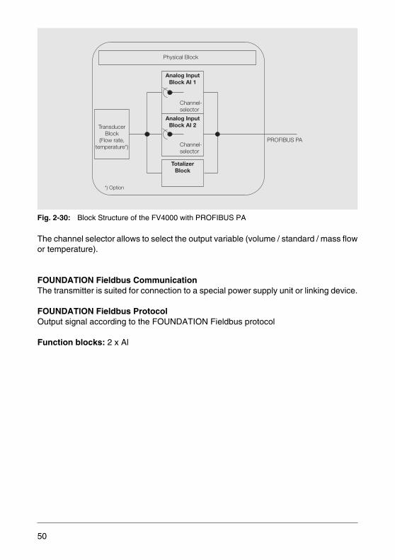
Fig. 2-30: Block Structure of the FV4000 with PROFIBUS PA
The channel selector allows to select the output variable (volume / standard / mass flowor temperature).
FOUNDATION Fieldbus CommunicationThe transmitter is suited for connection to a special power supply unit or linking device.
FOUNDATlON Fieldbus ProtocolOutput signal according to the FOUNDATION Fieldbus protocol
Function blocks: 2 x Al
PROFIBUS PA
*) Option
Physical Block
Channel-selector
Channel-selector
TransducerBlock
(Flow rate,temperature*)
Analog InputBlock AI 1
Analog InputBlock AI 2
TotalizerBlock
50
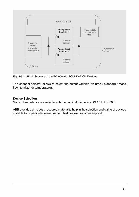
Fig. 2-31: Block Structure of the FV4000 with FOUNDATION FieIdbus
The channel selector allows to select the output variable (volume / standard / massflow, totalizer or temperature).
Device SelectionVortex flowmeters are available with the nominal diameters DN 15 to DN 300.
ABB provides at no cost, resource material to help in the selection and sizing of devicessuitable for a particular measurement task, as well as order support.
FOUNDATIONFieldbus
*) Option
Resource Block
Channel-selector
Channel-selector
TransducerBlock
(Flow rate,temperature*)
Analog InputBlock AI 1
Analog InputBlock AI 2
FF compatiblecommunication
stack
51

Dimensioning of the Measuring Ranges
Tab. 2-1: Vortex Flowmeter FV4000, Measuring Ranges
The values in the table are intended to be used as references. The – seen from thephysical point of view – actually achievable lower range values primarily depend on theoperating density or viscosity of the measuring medium and the presence/absence ofvibrations and/or pulsations. The measuring ranges for which the specified accuracy isreached depend on the minimum required Reynolds number, as below this number nolinear relationship can be established between the vortex shedding frequency and theflow velocity.
Nominal Diameter Water Gas
DN inch Span [m3/h] Span [m3/h]
15 ½ 0.5...6 4...24
25 1 0.8...18 14...150
40 1½ 2.4...48 30...390
50 2 3.0...70 40...500
80 3 8.0...170 90...1200
100 4 10.0...270 150...1900
150 6 30.0...630 300...4500
200 8 70.0...1100 250...8000
250 10 60.0...1700 800...14000
300 12 95.0...2400 1400...20000
ρ 1000 kg m3⁄=
v 1 106m2 s⁄⋅=
ρ 1 2· kg m3⁄,=
η 18 2, 106 Pa s⋅ ⋅=
52
To avoid cavitation, a positive pressure must be maintained in the measuring sectionwhich can be calculated as follows:
p2 = Static gauge pressure downstream of the devicepD = Steam pressure of liquid at operating temperatureΔp = Pressure drop (diagram Fig. 2-32)
When selecting devices for gas or steam measurement, it must be taken into accountthat the values in the table refer to air and that the vortex flowmeter measures in unitsat operating conditions. For this reason, first the operating density must be calculated:
(ρN = Standard density)
Then the flow rate in units at operating conditions is calculated:
qm = Mass flow rate in kg/hqn = Standard flow in m3/h
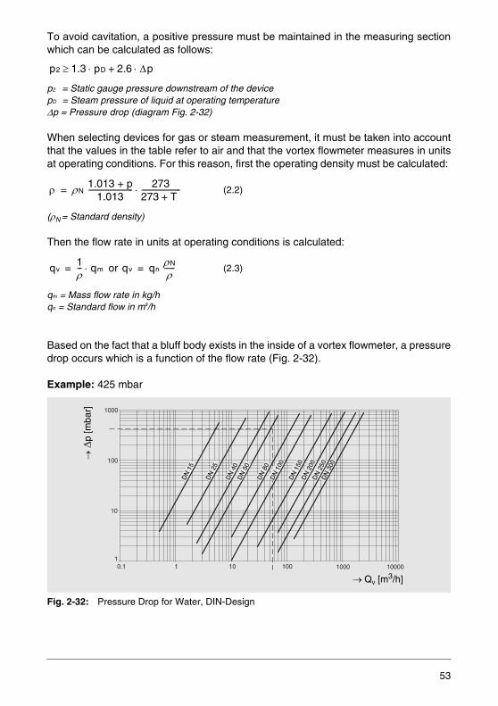
Based on the fact that a bluff body exists in the inside of a vortex flowmeter, a pressuredrop occurs which is a function of the flow rate (Fig. 2-32).
Example: 425 mbar
Fig. 2-32: Pressure Drop for Water, DIN-Design
(2.2)
or (2.3)
p2 1.3 pD 2.6 Δp⋅+⋅≥
ρ ρN 1.013 + p1.013
------------------------- 273273 T +----------------------⋅=
qv1ρ--- qm⋅= qv qn ρN
ρ------=
1
10
100
1000
0.1 1 10 100 1000 10000
DN
15
DN
25
DN
40
DN
50
DN
80
DN
100
DN
150
DN
200
DN
250
DN
300
→ Δ
p [m
bar]
→ Qv [m3/h]
53
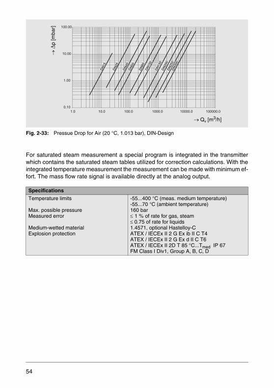
Fig. 2-33: Pressue Drop for Air (20 °C, 1.013 bar), DIN-Design
For saturated steam measurement a special program is integrated in the transmitterwhich contains the saturated steam tables utilized for correction calculations. With theintegrated temperature measurement the measurement can be made with minimum ef-fort. The mass flow rate signal is available directly at the analog output.
Specifications
Temperature limits
Max. possible pressureMeasured error
Medium-wetted materialExplosion protection
-55...400 °C (meas. medium temperature)-55...70 °C (ambient temperature)160 bar≤ 1 % of rate for gas, steam≤ 0.75 of rate for liquids1.4571, optional Hastelloy-CATEX / IECEx II 2 G Ex ib II C T4ATEX / IECEx II 2 G Ex d II C T6ATEX / IECEx II 2D T 85 °C...Tmed IP 67FM Class I Div1, Group A, B, C, D
0.10
1.00
10.00
100.00
1.0 10.0 100.0 1000.0 10000.0 100000.0
DN
150
DN
200
DN
250
DN
300
DN
15
DN
25
DN
50
DN
40
DN
80D
N10
0
→ Δ
p [m
bar]
→ Qv [m3/h]
54
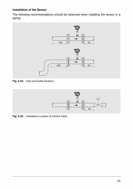
Installation of the Sensor
The following recommendations should be observed when installing the sensor in apiping:
Fig. 2-34: Inlet and Outlet Sections
Fig. 2-35: Installation Location of Control Valve
15D 5D
25D 5D
5D
55
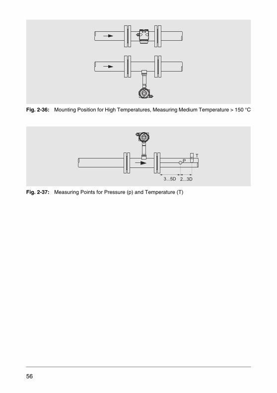
Fig. 2-36: Mounting Position for High Temperatures, Measuring Medium Temperature > 150 °C
Fig. 2-37: Measuring Points for Pressure (p) and Temperature (T)
3...5D 2...3D
TP
56
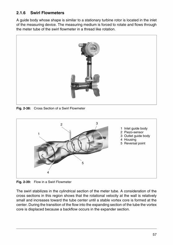
2.1.6 Swirl Flowmeters
A guide body whose shape is similar to a stationary turbine rotor is located in the inletof the measuring device. The measuring medium is forced to rotate and flows throughthe meter tube of the swirl flowmeter in a thread like rotation.
Fig. 2-38: Cross Section of a Swirl Flowmeter
Fig. 2-39: Flow in a Swirl Flowmeter
The swirl stabilizes in the cylindrical section of the meter tube. A consideration of thecross sections in this region shows that the rotational velocity at the wall is relativelysmall and increases toward the tube center until a stable vortex core is formed at thecenter. During the transition of the flow into the expanding section of the tube the vortexcore is displaced because a backflow occurs in the expander section.
2 3
1
4
5
1 Inlet guide body2 Piezo-sensor3 Outlet guide body4 Housing5 Reversal point
57
The vortex core forms a spiral like secondary rotation whose frequency is linearly pro-portional to the flow rate over a wide range. This secondary rotation is measured witha Piezo-sensor. The Piezo-sensor utilizes the resultant pressure differences for itspulse measurements.
The same sensors are used in both the swirl and vortex flowmeters. The vortex shed-ding frequency is between 1 and 2000 Hz; the higher frequencies indicating higher flowrates.
In the transmiter the sensor signals are converted into further processable outputs. Thesame transmitters as described for the vortex flowmeters are used.
Fig. 2-40: Integral Mount Design: FS4000-ST4
Swirl flowmeters can be used for measuring the flow of liquids, gases and steam.
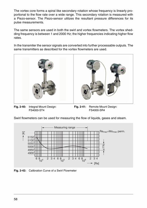
Fig. 2-42: Calibration Curve of a Swirl Flowmeter
Fig. 2-41: Remote Mount Design: FS4000-SR4
6 8104 6432 8
105 6432 4328106
490049505000505051005150
Measuring rangeRemax=Momax perm.
±1%
[K]
[Re]
58
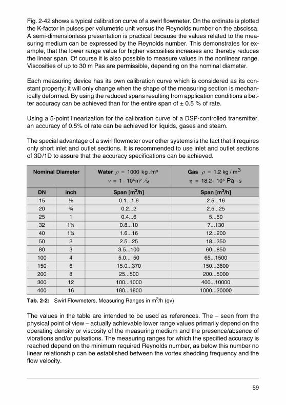
Fig. 2-42 shows a typical calibration curve of a swirl flowmeter. On the ordinate is plottedthe K-factor in pulses per volumetric unit versus the Reynolds number on the abscissa.A semi-dimensionless presentation is practical because the values related to the mea-suring medium can be expressed by the Reynolds number. This demonstrates for ex-ample, that the lower range value for higher viscosities increases and thereby reducesthe linear span. Of course it is also possible to measure values in the nonlinear range.Viscosities of up to 30 m Pas are permissible, depending on the nominal diameter.
Each measuring device has its own calibration curve which is considered as its con-stant property; it will only change when the shape of the measuring section is mechan-ically deformed. By using the reduced spans resulting from application conditions a bet-ter accuracy can be achieved than for the entire span of ± 0.5 % of rate.
Using a 5-point linearization for the calibration curve of a DSP-controlled transmitter,an accuracy of 0.5% of rate can be achieved for liquids, gases and steam.
The special advantage of a swirl flowmeter over other systems is the fact that it requiresonly short inlet and outlet sections. It is recommended to use inlet and outlet sectionsof 3D/1D to assure that the accuracy specifications can be achieved.
Tab. 2-2: Swirl Flowmeters, Measuring Ranges in m3/h (qv)
The values in the table are intended to be used as references. The – seen from thephysical point of view – actually achievable lower range values primarily depend on theoperating density or viscosity of the measuring medium and the presence/absence ofvibrations and/or pulsations. The measuring ranges for which the specified accuracy isreached depend on the minimum required Reynolds number, as below this number nolinear relationship can be established between the vortex shedding frequency and theflow velocity.
Nominal Diameter Water Gas
DN inch Span [m3/h] Span [m3/h]
15 ½ 0.1...1.6 2.5...16
20 ¾ 0.2...2 2.5...25
25 1 0.4...6 5...50
32 1¼ 0.8...10 7...130
40 1¼ 1.6...16 12...200
50 2 2.5...25 18...350
80 3 3.5...100 60...850
100 4 5.0... 50 65...1500
150 6 15.0...370 150...3600
200 8 25...500 200...5000
300 12 100...1000 400...10000
400 16 180...1800 1000...20000
ρ 1000 kg m3⁄=
v 1 106m2 s⁄⋅=
ρ 1.2 kg / m3=
η 18.2 106 Pa s⋅ ⋅=
59
Device Selection
Swirl flowmeters are with the nominal diameters DN 15...DN 400. Tab. 2-2 shows thecorresponding measuring ranges. For liquid measurements the maximum flow velocityis 6 m/s, for gases it is 50 m/s.
ABB provides, at no cost, resource material to help in the selection and sizing of devic-es suitable for a particular measurement task, as well as order support.
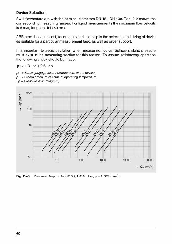
It is important to avoid cavitation when measuring liquids. Sufficient static pressuremust exist in the measuring section for this reason. To assure satisfactory operationthe following check should be made:
p2 = Static gauge pressure downstream of the devicepD = Steam pressure of liquid at operating temperature Δp = Pressure drop (diagram)
Fig. 2-43: Pressure Drop for Air (22 °C; 1,013 mbar, ρ = 1.205 kg/m3)
p2 1.3 pD 2.6 Δp⋅+⋅≥
0.1
1
10
100
1000
1 10 100 1000 10000 100000
DN 15
DN 20
DN 40
DN 50
DN 80
DN 100
DN 150
DN 200
DN 300
DN 400
DN 25
DN 32
→ Δ
p [m
bar]
→ Qv [m3/h]
60
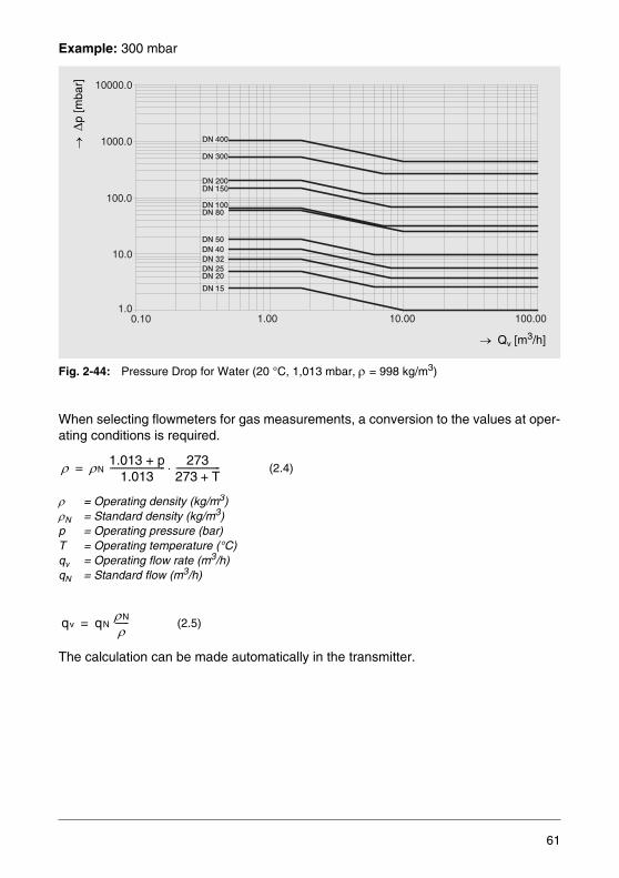
Example: 300 mbar
Fig. 2-44: Pressure Drop for Water (20 °C, 1,013 mbar, ρ = 998 kg/m3)
When selecting flowmeters for gas measurements, a conversion to the values at oper-ating conditions is required.
ρ = Operating density (kg/m3)ρN = Standard density (kg/m3)p = Operating pressure (bar)T = Operating temperature (°C)qv = Operating flow rate (m3/h)qN = Standard flow (m3/h)
The calculation can be made automatically in the transmitter.
(2.4)
(2.5)
1.0
10.0
100.0
1000.0
10000.0
0.10 1.00 10.00 100.00
DN 15
DN 50DN 40
DN 25
DN 200DN 150
DN 100DN 80
DN 300
DN 20
DN 32
DN 400
→ Qv [m3/h]
→ Δ
p [m
bar]
ρ ρN 1.013 + p1.013
------------------------- 273273 T+--------------------⋅=
qv qN ρN
ρ------=
61

Transmitter
The transmitter used for the swirl flowmeter is the same as the one described for thevortex flowmeter.
Specifications
Temperature limits
Max. possible pressureMeasured errorMedium-wetted materialsExplosion protection
-55...280 °C (meas. medium temperature)-55...70 °C (ambient temperature) 40 bar0.5 % of rate1.4571 (Hastelloy C)ATEX / IECEx II 2 G Ex ib II C T4ATEX / IECEx II 2 G Ex d II C T6ATEX / IECEx II 2D T 85 °C...Tmed IP 67FM Class I Div1, Group A, B, C, D
62
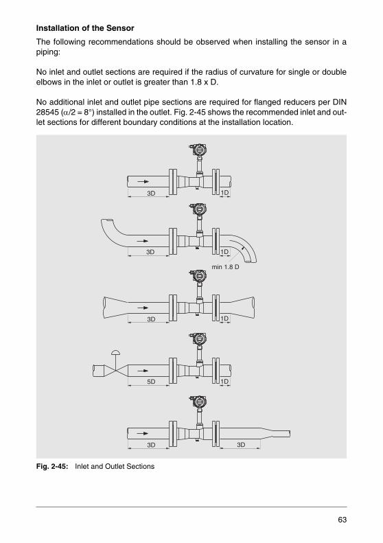
Installation of the Sensor
The following recommendations should be observed when installing the sensor in apiping:
No inlet and outlet sections are required if the radius of curvature for single or doubleelbows in the inlet or outlet is greater than 1.8 x D.
No additional inlet and outlet pipe sections are required for flanged reducers per DIN28545 (α/2 = 8°) installed in the outlet. Fig. 2-45 shows the recommended inlet and out-let sections for different boundary conditions at the installation location.
Fig. 2-45: Inlet and Outlet Sections
3D
3D 1D
1D
min 1.8 D
3D
5D
1D
1D
3D 3D
63

Fig. 2-46: Mounting Position for High Measuring Medium Temperatures > 150 °C
Multivariable Devices
Devices, which measure more that one physical variable are referred to as multivari-able measuring devices. They can be provided with an optional Pt 100 for integratedtemperature measurement directly in the sensor.
To convert the flow measurements to normal or mass units in many instances an addi-tional temperature measurement is all that is required, e.g. for saturated steam or forgas measurements when the pressure remains constant.
Compensation of Pressure Effects
Integrated Temperature MeasurementMeasuring the temperature and the flow rate at the same location provides appreciableadvantages:
– High accuracy through optimal positioning of the temperature sensor– No cabling– Short response time
Fig. 2-47: Sensor for Flow Rate (F) and Temperature (T) Measurement
F
T
64

Pressure and Temperature Compensation
If the process conditions are such that pressure variations occur or the measuring me-dium is superheated steam, then an integrated temperature measurement alone is notsufficient to convert the gas flow volume measurements to mass, standard or steammass flow values. For these applications swirl and vortex flowmeters in conjunctionwith flow computer units are the best choice. The power supply is realized via the flowcomputer unit.
Components Used
– Vortex or swirl flowmeter– Transmitter for absolute pressure– Resistance thermometer, optionally with integral transmitter– Flow computer unit
Flow computer unit
Temperature sensor
Pressure transmitter
Flowmeter
65
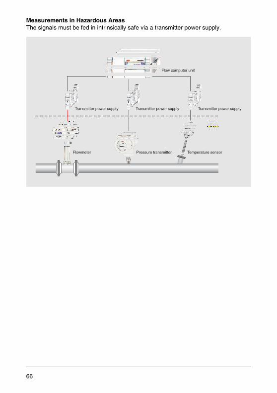
Measurements in Hazardous Areas The signals must be fed in intrinsically safe via a transmitter power supply.
Flow computer unit
Temperature sensorPressure transmitterFlowmeter
Transmitter power supplyTransmitter power supply Transmitter power supply
66
2.2 Flowmeters
2.2.1 Flowmeters for Differential Pressure Measurement
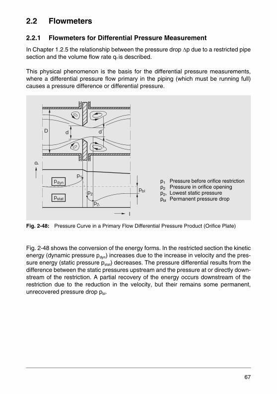
In Chapter 1.2.5 the relationship between the pressure drop Δp due to a restricted pipesection and the volume flow rate qv is described.
This physical phenomenon is the basis for the differential pressure measurements,where a differential pressure flow primary in the piping (which must be running full)causes a pressure difference or differential pressure.
Fig. 2-48: Pressure Curve in a Primary Flow Differential Pressure Product (Orifice Plate)
Fig. 2-48 shows the conversion of the energy forms. In the restricted section the kineticenergy (dynamic pressure pdyn) increases due to the increase in velocity and the pres-sure energy (static pressure pstat) decreases. The pressure differential results from thedifference between the static pressures upstream and the pressure at or directly down-stream of the restriction. A partial recovery of the energy occurs downstream of therestriction due to the reduction in the velocity, but their remains some permanent,unrecovered pressure drop pbl.
p1
p2
p2,
pdyn
pstat
d´dD
pbl
p
I
p1 Pressure before orifice restrictionp2 Pressure in orifice openingp2, Lowest static pressurepbl Permanent pressure drop
67
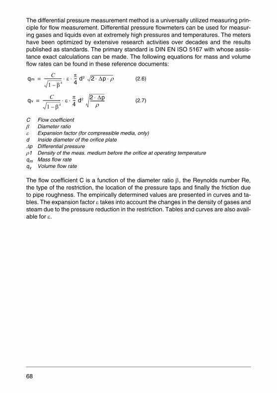
The differential pressure measurement method is a universally utilized measuring prin-ciple for flow measurement. Differential pressure flowmeters can be used for measur-ing gases and liquids even at extremely high pressures and temperatures. The metershave been optimized by extensive research activities over decades and the resultspublished as standards. The primary standard is DIN EN ISO 5167 with whose assis-tance exact calculations can be made. The following equations for mass and volumeflow rates can be found in these reference documents:
C Flow coefficient β Diameter ratio ε Expansion factor (for compressible media, only) d Inside diameter of the orifice plateΔp Differential pressure ρ1 Density of the meas. medium before the orifice at operating temperature qm Mass flow rateqv Volume flow rate
The flow coefficient C is a function of the diameter ratio β, the Reynolds number Re,the type of the restriction, the location of the pressure taps and finally the friction dueto pipe roughness. The empirically determined values are presented in curves and ta-bles. The expansion factor ε takes into account the changes in the density of gases andsteam due to the pressure reduction in the restriction. Tables and curves are also avail-able for ε.
(2.6)
(2.7)
qmC
1 β4–------------------ ε π
4--- d2 2 Δp ρ⋅ ⋅⋅ ⋅=
qvC
1 β4–------------------ ε π
4--- d2 2 Δp⋅
ρ---------------⋅ ⋅=
68
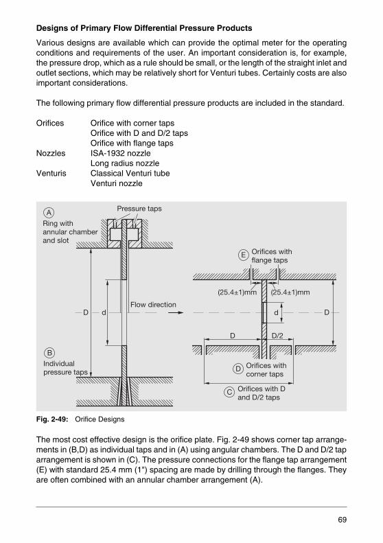
Designs of Primary Flow Differential Pressure Products
Various designs are available which can provide the optimal meter for the operatingconditions and requirements of the user. An important consideration is, for example,the pressure drop, which as a rule should be small, or the length of the straight inlet andoutlet sections, which may be relatively short for Venturi tubes. Certainly costs are alsoimportant considerations.
The following primary flow differential pressure products are included in the standard.
Orifices Orifice with corner tapsOrifice with D and D/2 tapsOrifice with flange taps
Nozzles ISA-1932 nozzleLong radius nozzle
Venturis Classical Venturi tubeVenturi nozzle
Fig. 2-49: Orifice Designs
The most cost effective design is the orifice plate. Fig. 2-49 shows corner tap arrange-ments in (B,D) as individual taps and in (A) using angular chambers. The D and D/2 taparrangement is shown in (C). The pressure connections for the flange tap arrangement(E) with standard 25.4 mm (1") spacing are made by drilling through the flanges. Theyare often combined with an annular chamber arrangement (A).
Flow direction
A
Ring withannular chamberand slot
B
Individualpressure taps
Pressure taps
E Orifices withflange taps
C Orifices with Dand D/2 taps
D Orifices withcorner taps
(25.4±1)mm
dd D
D
D
D/2
(25.4±1)mm
69

Nozzles have lower pressure drops, but require especially precise manufacture. Fig.2-50 (B) shows an ISA 1932 nozzle and its installation with corner taps (A, lower) andwith an annular chamber (upper). Long radius nozzles (C, D) are available for large andsmall diameters. Their installation is shown in (A).
Fig. 2-50: Nozzle Designs
Venturi tubes and Venturi nozzles are characterized by small pressure drops. Both arealso available in shortened versions. The fact that the pressure drop is an importantfactor in evaluating the various designs is shown by the curves (Fig. 2-52).
Pressure drop means energy loss and increased pumping/compression.
A B C D
F
Ød
Øc
ØD
Ød
ØD
ØD
FØ
d ØD
Flowdirection
0.6041 d
0.6041dD/2 0.6d D
/2
0.6ddD-d 2
d> D23
d> D23
d7 6
H H H
d2 3 Ø
dF
Largediameter ratio0.25 0.8≤ β ≤
Smalldiameter ratio0.20 0.5≤ β ≤
70
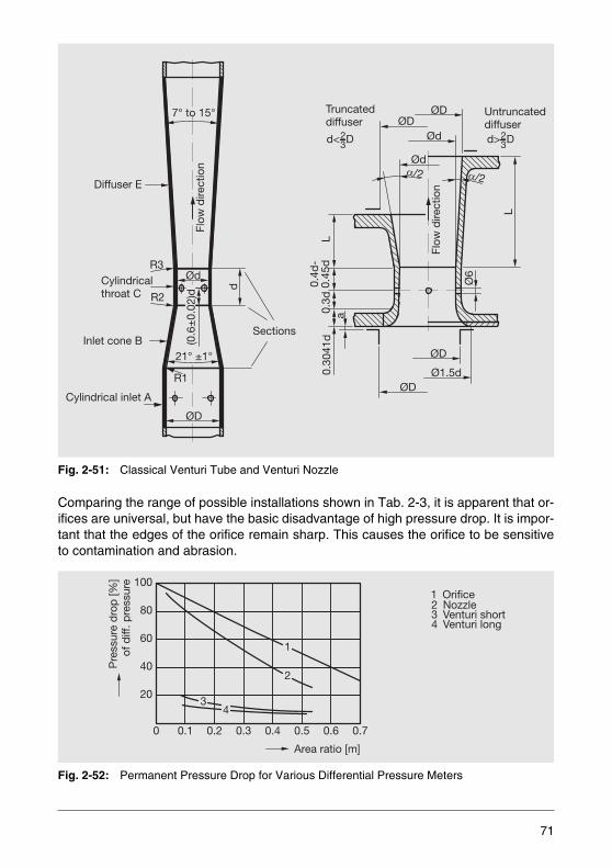
Fig. 2-51: Classical Venturi Tube and Venturi Nozzle
Comparing the range of possible installations shown in Tab. 2-3, it is apparent that or-ifices are universal, but have the basic disadvantage of high pressure drop. It is impor-tant that the edges of the orifice remain sharp. This causes the orifice to be sensitiveto contamination and abrasion.
Fig. 2-52: Permanent Pressure Drop for Various Differential Pressure Meters
Diffuser E
Cylindricalthroat C
Inlet cone B
Cylindrical inlet A
R3
R2
Sections
d
7° to 15°
Flow
dire
ctio
n
Ød
ØD
(0.6
±0.
02)d
21° ±1°
L
Ø6
a0.
3041
d0.
3dL
0.4d
-0.
45d
Ød
Ød
ØDTruncateddiffuser
Untruncateddiffuser
ØD
Ø1.5dØD
ØD
Flow
dire
ctio
n
d< D23 d> D2
3
R1
20
40
60
80
100
1
2
34
Pre
ssur
e d
rop
[%]
of d
iff. p
ress
ure
2 Nozzle
4 Venturi long3 Venturi short
1 Orifice
Area ratio [m]
0 0.1 0.2 0.3 0.4 0.5 0.6 0.7
71
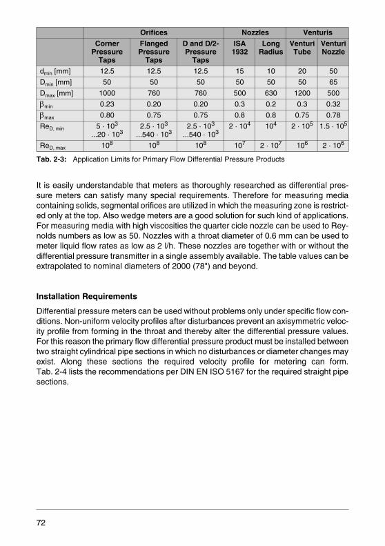
Tab. 2-3: Application Limits for Primary Flow Differential Pressure Products
It is easily understandable that meters as thoroughly researched as differential pres-sure meters can satisfy many special requirements. Therefore for measuring mediacontaining solids, segmental orifices are utilized in which the measuring zone is restrict-ed only at the top. Also wedge meters are a good solution for such kind of applications.For measuring media with high viscosities the quarter cicle nozzle can be used to Rey-nolds numbers as low as 50. Nozzles with a throat diameter of 0.6 mm can be used tometer liquid flow rates as low as 2 l/h. These nozzles are together with or without thedifferential pressure transmitter in a single assembly available. The table values can beextrapolated to nominal diameters of 2000 (78") and beyond.
Installation Requirements
Differential pressure meters can be used without problems only under specific flow con-ditions. Non-uniform velocity profiles after disturbances prevent an axisymmetric veloc-ity profile from forming in the throat and thereby alter the differential pressure values.For this reason the primary flow differential pressure product must be installed betweentwo straight cylindrical pipe sections in which no disturbances or diameter changes mayexist. Along these sections the required velocity profile for metering can form.Tab. 2-4 lists the recommendations per DIN EN ISO 5167 for the required straight pipesections.
Orifices Nozzles Venturis
CornerPressure
Taps
FlangedPressure
Taps
D and D/2-Pressure
Taps
ISA1932
LongRadius
VenturiTube
VenturiNozzle
dmin [mm] 12.5 12.5 12.5 15 10 20 50
Dmin [mm] 50 50 50 50 50 50 65
Dmax [mm] 1000 760 760 500 630 1200 500
βmin 0.23 0.20 0.20 0.3 0.2 0.3 0.32
βmax 0.80 0.75 0.75 0.8 0.8 0.75 0.78
ReD, min 5 · 103
...20 · 1032.5 · 103
...540 · 1032.5 · 103
...540 · 1032 · 104 104 2 · 105 1.5 · 105
ReD, max 108 108 108 107 2 · 107 106 2 · 106
72
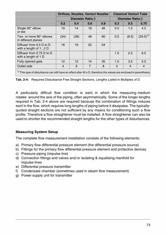
Tab. 2-4: Required Disturbance Free Straight Sections, Lengths Listed in Multiples of D
A particularly difficult flow condition is swirl, in which the measuring mediumrotates around the axis of the piping, often asymmetrically. Some of the longer lengthsrequired in Tab. 2-4 above are required because the combination of fittings inducesswirl in the flow, which requires long lengths of piping before it dissipates. The typically-quoted straight sections are not sufficient by any means for conditioning such a flowprofile. Therefore a flow straightener must be installed. A flow straightener can also beused to shorten the recommended straight lengths for the other types of disturbances.
Measuring System Setup
The complete flow measurement installation consists of the following elements:
a) Primary flow differential pressure element (the differential pressure source)b) Fittings for the primary flow differential pressure element and protective devicesc) Pressure piping (impulse line)d) Connection fittings and valves and/or isolating & equalising manifold for
impulse linese) Differential pressure transmitterf) Condensate chamber (sometimes used in steam flow measurement)g) Power supply unit for transmitter
Orifices, Nozzles, Venturi Nozzles Classical Venturi Tube
Diameter Ratio β Diameter Ratio β0.2 0.4 0.6 0.8 0.3 0.5 0.75
Single 90° elbowor tee
10 14 18 46 0.5 1.5 4.5
Two or more 90° elbowsin different planes
(34) (36) 48 80 0.5 (8.5) (29.5)1)
Diffuser from 0.5 D to Dwith a length of 1...2 D
16 16 22 54
Diffuser from 0.75 D to D with a length of 1 D
1.5 2.5 6.5
Fully opened gate 12 12 14 30 1.5 3.5 5.5
Outlet side 4 6 7 8 4 4 4
1) This type of disturbance can still have an affect after 40 x D, therefore the values are enclosed in parenthesis.
73
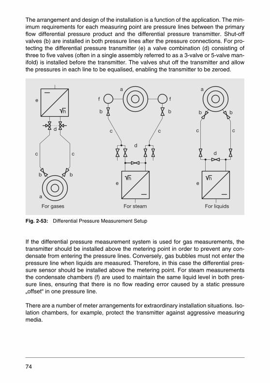
The arrangement and design of the installation is a function of the application. The min-imum requirements for each measuring point are pressure lines between the primaryflow differential pressure product and the differential pressure transmitter. Shut-offvalves (b) are installed in both pressure lines after the pressure connections. For pro-tecting the differential pressure transmitter (e) a valve combination (d) consisting ofthree to five valves (often in a single assembly referred to as a 3-valve or 5-valve man-ifold) is installed before the transmitter. The valves shut off the transmitter and allowthe pressures in each line to be equalised, enabling the transmitter to be zeroed.
Fig. 2-53: Differential Pressure Measurement Setup
If the differential pressure measurement system is used for gas measurements, thetransmitter should be installed above the metering point in order to prevent any con-densate from entering the pressure lines. Conversely, gas bubbles must not enter thepressure line when liquids are measured. Therefore, in this case the differential pres-sure sensor should be installed above the metering point. For steam measurementsthe condensate chambers (f) are used to maintain the same liquid level in both pres-sure lines, ensuring that there is no flow reading error caused by a static pressure„offset“ in one pressure line.
There are a number of meter arrangements for extraordinary installation situations. Iso-lation chambers, for example, protect the transmitter against aggressive measuringmedia.
e
h
d
c c
b b
a
For gases
a
f
b
c c
d
e
For steam
b
f
h
a
h
b
c
d
e
For liquids
c
b
74
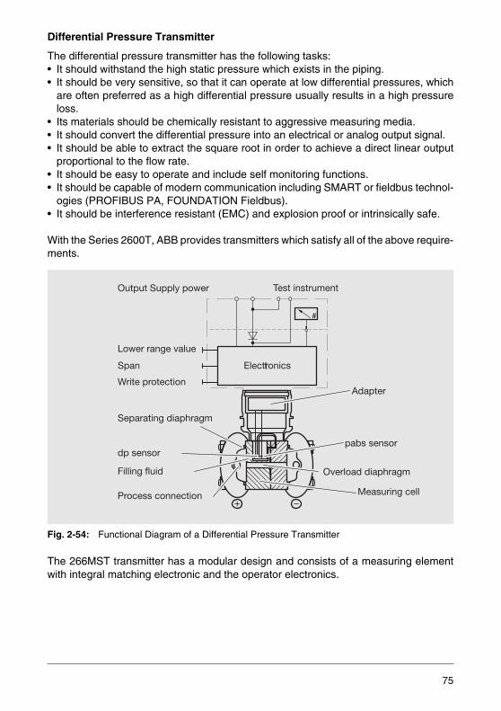
Differential Pressure Transmitter
The differential pressure transmitter has the following tasks:• It should withstand the high static pressure which exists in the piping.• It should be very sensitive, so that it can operate at low differential pressures, which
are often preferred as a high differential pressure usually results in a high pressureloss.
• Its materials should be chemically resistant to aggressive measuring media.• It should convert the differential pressure into an electrical or analog output signal.• It should be able to extract the square root in order to achieve a direct linear output
proportional to the flow rate.• It should be easy to operate and include self monitoring functions.• It should be capable of modern communication including SMART or fieldbus technol-
ogies (PROFIBUS PA, FOUNDATION Fieldbus).• It should be interference resistant (EMC) and explosion proof or intrinsically safe.
With the Series 2600T, ABB provides transmitters which satisfy all of the above require-ments.
Fig. 2-54: Functional Diagram of a Differential Pressure Transmitter
The 266MST transmitter has a modular design and consists of a measuring elementwith integral matching electronic and the operator electronics.
#
Separating diaphragm
dp sensorpabs sensor
Adapter
Filling fluid
Process connection
Overload diaphragm
Measuring cell
Lower range value
Span
Write protection
Output Supply power Test instrument
Electronicst
75
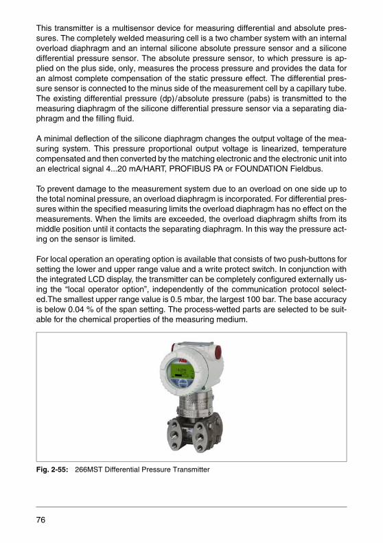
This transmitter is a multisensor device for measuring differential and absolute pres-sures. The completely welded measuring cell is a two chamber system with an internaloverload diaphragm and an internal silicone absolute pressure sensor and a siliconedifferential pressure sensor. The absolute pressure sensor, to which pressure is ap-plied on the plus side, only, measures the process pressure and provides the data foran almost complete compensation of the static pressure effect. The differential pres-sure sensor is connected to the minus side of the measurement cell by a capillary tube.The existing differential pressure (dp)/absolute pressure (pabs) is transmitted to themeasuring diaphragm of the silicone differential pressure sensor via a separating dia-phragm and the filling fluid.
A minimal deflection of the silicone diaphragm changes the output voltage of the mea-suring system. This pressure proportional output voltage is linearized, temperaturecompensated and then converted by the matching electronic and the electronic unit intoan electrical signal 4...20 mA/HART, PROFIBUS PA or FOUNDATION Fieldbus.
To prevent damage to the measurement system due to an overload on one side up tothe total nominal pressure, an overload diaphragm is incorporated. For differential pres-sures within the specified measuring limits the overload diaphragm has no effect on themeasurements. When the limits are exceeded, the overload diaphragm shifts from itsmiddle position until it contacts the separating diaphragm. In this way the pressure act-ing on the sensor is limited.
For local operation an operating option is available that consists of two push-buttons forsetting the lower and upper range value and a write protect switch. In conjunction withthe integrated LCD display, the transmitter can be completely configured externally us-ing the “local operator option”, independently of the communication protocol select-ed.The smallest upper range value is 0.5 mbar, the largest 100 bar. The base accuracyis below 0.04 % of the span setting. The process-wetted parts are selected to be suit-able for the chemical properties of the measuring medium.
Fig. 2-55: 266MST Differential Pressure Transmitter
76
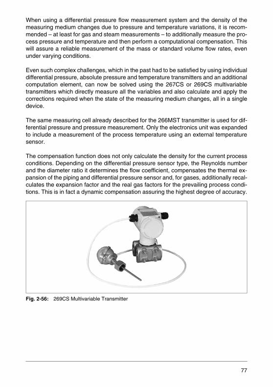
When using a differential pressure flow measurement system and the density of themeasuring medium changes due to pressure and temperature variations, it is recom-mended – at least for gas and steam measurements – to additionally measure the pro-cess pressure and temperature and then perform a computational compensation. Thiswill assure a reliable measurement of the mass or standard volume flow rates, evenunder varying conditions.
Even such complex challenges, which in the past had to be satisfied by using individualdifferential pressure, absolute pressure and temperature transmitters and an additionalcomputation element, can now be solved using the 267CS or 269CS multivariabletransmitters which directly measure all the variables and also calculate and apply thecorrections required when the state of the measuring medium changes, all in a singledevice.
The same measuring cell already described for the 266MST transmitter is used for dif-ferential pressure and pressure measurement. Only the electronics unit was expandedto include a measurement of the process temperature using an external temperaturesensor.
The compensation function does not only calculate the density for the current processconditions. Depending on the differential pressure sensor type, the Reynolds numberand the diameter ratio it determines the flow coefficient, compensates the thermal ex-pansion of the piping and differential pressure sensor and, for gases, additionally recal-culates the expansion factor and the real gas factors for the prevailing process condi-tions. This is in fact a dynamic compensation assuring the highest degree of accuracy.
Fig. 2-56: 269CS Multivariable Transmitter
77
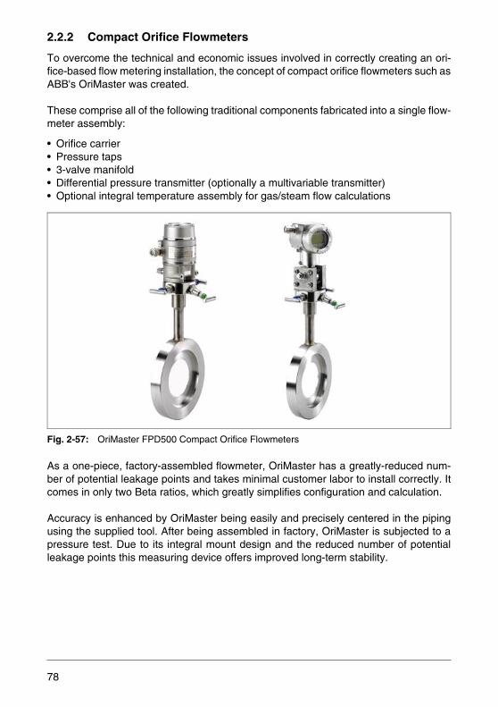
2.2.2 Compact Orifice Flowmeters
To overcome the technical and economic issues involved in correctly creating an ori-fice-based flow metering installation, the concept of compact orifice flowmeters such asABB's OriMaster was created.
These comprise all of the following traditional components fabricated into a single flow-meter assembly:
• Orifice carrier• Pressure taps• 3-valve manifold• Differential pressure transmitter (optionally a multivariable transmitter)• Optional integral temperature assembly for gas/steam flow calculations
Fig. 2-57: OriMaster FPD500 Compact Orifice Flowmeters
As a one-piece, factory-assembled flowmeter, OriMaster has a greatly-reduced num-ber of potential leakage points and takes minimal customer labor to install correctly. Itcomes in only two Beta ratios, which greatly simplifies configuration and calculation.
Accuracy is enhanced by OriMaster being easily and precisely centered in the pipingusing the supplied tool. After being assembled in factory, OriMaster is subjected to apressure test. Due to its integral mount design and the reduced number of potentialleakage points this measuring device offers improved long-term stability.
78
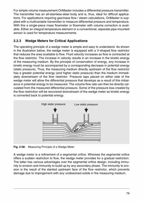
For simple volume measurement OriMaster includes a differential pressure transmitter.The transmitter has an all-stainless-steel body and is, thus, ideal for difficult applica-tions. For applications requiring gas/mass flow / steam calculations, OriMaster is sup-plied with a multivariable transmitter to measure differential pressure and temperature.With this a single-piece mass flowmeter or flowmeter with volume correction is avail-able. Either an integral temperature element or a conventional, separate pipe-mountedsensor is used for temperature measurements.
2.2.3 Wedge Meters for Critical Applications
The operating principle of a wedge meter is simple and easy to understand. As shownin the illustration below, the wedge meter is equipped with a V-shaped flow restrictorthat reduces the area available to flow. Fluid velocity increases as flow is contracted atthe flow restrictor. The increase in velocity results in an increase in the kinetic energyof the measuring medium. By the principle of conservation of energy, any increase inkinetic energy must be accompanied by a corresponding decrease in potential energy(static pressure). Thus, the measuring medium directly upstream of the flow restrictorhas a greater potential energy (and higher static pressure) than the medium immedi-ately downstream of the flow restrictor. Pressure taps placed on either side of thewedge meter will allow the differential pressure that develops as a result of this imbal-ance in potential energy to be measured. The volume flow rate can then be directly cal-culated from the measured differential pressure. Some of the pressure loss created bythe flow restriction will be recovered downstream of the wedge meter as kinetic energyis converted back to potential energy.
Fig. 2-58: Measuring Principle of a Wedge Meter
A wedge meter is a refinement of a segmental orifice. Whereas the segmental orificeoffers a sudden restriction to flow, the wedge meter provides for a gradual restriction.The latter has various advantages over the segmental orifice design, including immu-nity to erosion and immunity to build-up by any secondary phase. The immunity to ero-sion is the result of the slanted upstream face of the flow restrictor, which preventsdamage due to impingement with any undissolved solids in the measuring medium.
High static pressure Low static pressure
79
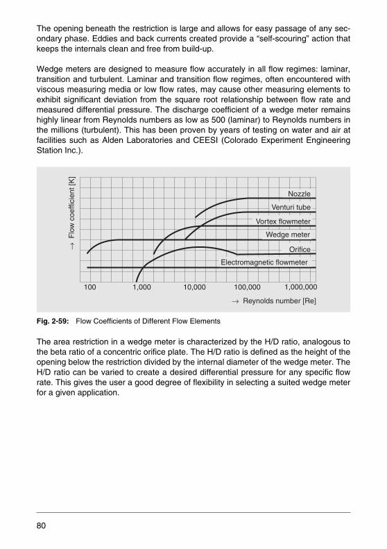
The opening beneath the restriction is large and allows for easy passage of any sec-ondary phase. Eddies and back currents created provide a “self-scouring” action thatkeeps the internals clean and free from build-up.
Wedge meters are designed to measure flow accurately in all flow regimes: laminar,transition and turbulent. Laminar and transition flow regimes, often encountered withviscous measuring media or low flow rates, may cause other measuring elements toexhibit significant deviation from the square root relationship between flow rate andmeasured differential pressure. The discharge coefficient of a wedge meter remainshighly linear from Reynolds numbers as low as 500 (laminar) to Reynolds numbers inthe millions (turbulent). This has been proven by years of testing on water and air atfacilities such as Alden Laboratories and CEESI (Colorado Experiment EngineeringStation Inc.).
Fig. 2-59: Flow Coefficients of Different Flow Elements
The area restriction in a wedge meter is characterized by the H/D ratio, analogous tothe beta ratio of a concentric orifice plate. The H/D ratio is defined as the height of theopening below the restriction divided by the internal diameter of the wedge meter. TheH/D ratio can be varied to create a desired differential pressure for any specific flowrate. This gives the user a good degree of flexibility in selecting a suited wedge meterfor a given application.
Venturi tube
Vortex flowmeter
Wedge meter
Orifice
Electromagnetic flowmeter
Nozzle
→F
low
coe
ffici
ent [
K]
→ Reynolds number [Re]
100 1,000 10,000 100,000 1,000,000
80
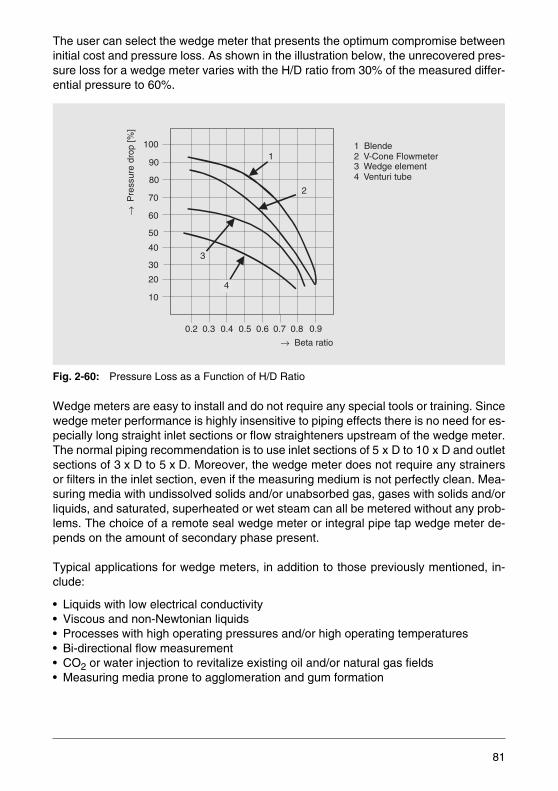
The user can select the wedge meter that presents the optimum compromise betweeninitial cost and pressure loss. As shown in the illustration below, the unrecovered pres-sure loss for a wedge meter varies with the H/D ratio from 30% of the measured differ-ential pressure to 60%.
Fig. 2-60: Pressure Loss as a Function of H/D Ratio
Wedge meters are easy to install and do not require any special tools or training. Sincewedge meter performance is highly insensitive to piping effects there is no need for es-pecially long straight inlet sections or flow straighteners upstream of the wedge meter.The normal piping recommendation is to use inlet sections of 5 x D to 10 x D and outletsections of 3 x D to 5 x D. Moreover, the wedge meter does not require any strainersor filters in the inlet section, even if the measuring medium is not perfectly clean. Mea-suring media with undissolved solids and/or unabsorbed gas, gases with solids and/orliquids, and saturated, superheated or wet steam can all be metered without any prob-lems. The choice of a remote seal wedge meter or integral pipe tap wedge meter de-pends on the amount of secondary phase present.
Typical applications for wedge meters, in addition to those previously mentioned, in-clude:
• Liquids with low electrical conductivity• Viscous and non-Newtonian liquids• Processes with high operating pressures and/or high operating temperatures• Bi-directional flow measurement• CO2 or water injection to revitalize existing oil and/or natural gas fields• Measuring media prone to agglomeration and gum formation
100
90
80
70
60
50
40
30
20
10
0.2 0.3 0.4 0.5 0.6 0.7 0.8 0.9
→P
ress
ure
drop
[%]
→ Beta ratio
1
2
3
1 Blende2 V-Cone Flowmeter3 Wedge element4 Venturi tube
4
81

2.2.4 Pitot Flowmeters
Averaging Pitot Tube
An averaging pitot tube is an insertion or fixed probe which spans the process pipe di-ameter. The outer pitot tube of the probe has a number of pressure sensing ports facingupstream which are positioned at equal annular points in accordance with a log-lineardistribution.
Fig. 2-61: Schema of an Averaging Pitot Tube
The total pressures developed at each upstream port are the sum of two pressures -the static pressure and the pressure caused by the impact of the flowing medium.These pressures are averaged within the probe and the resultant pressure is the highpressure output component of the probe. The spacing of the ports ensures that the re-sultant average represents the medium velocity of the measuring medium across thepipe diameter.
The low pressure component is generated from a single sensing port located on thedownstream side of the probe, measuring the static pressure. The difference betweenthe two pressures is proportional to the flow rate as follows:
Q = Volume flow ratek = ConstantA = Cross-section of the pipe/ducth = Generated differential pressurer = Density of the measuring medium
Differential pressure output connected to a differential pressure transmitter
High pressure sideLow pressure side
Torbar head
Torbar fitting
Low pressure chamber
Internalaveraging tube
Outer pitot tube
Q = k. A. hρ--- 1/2
82
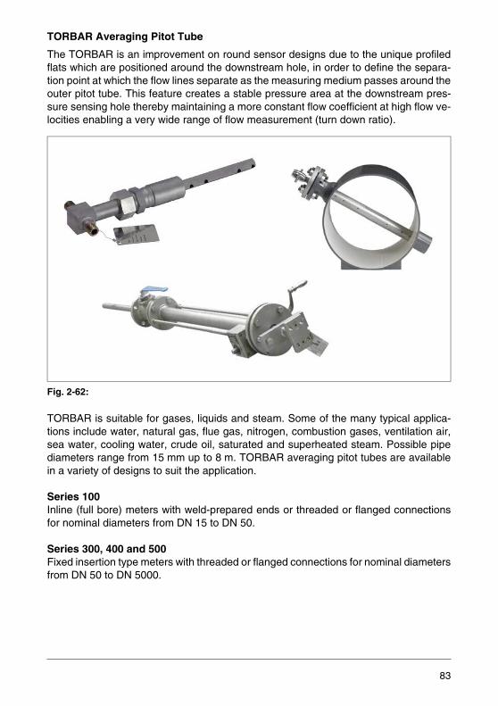
TORBAR Averaging Pitot Tube
The TORBAR is an improvement on round sensor designs due to the unique profiledflats which are positioned around the downstream hole, in order to define the separa-tion point at which the flow lines separate as the measuring medium passes around theouter pitot tube. This feature creates a stable pressure area at the downstream pres-sure sensing hole thereby maintaining a more constant flow coefficient at high flow ve-locities enabling a very wide range of flow measurement (turn down ratio).
Fig. 2-62:
TORBAR is suitable for gases, liquids and steam. Some of the many typical applica-tions include water, natural gas, flue gas, nitrogen, combustion gases, ventilation air,sea water, cooling water, crude oil, saturated and superheated steam. Possible pipediameters range from 15 mm up to 8 m. TORBAR averaging pitot tubes are availablein a variety of designs to suit the application.
Series 100Inline (full bore) meters with weld-prepared ends or threaded or flanged connectionsfor nominal diameters from DN 15 to DN 50.
Series 300, 400 and 500 Fixed insertion type meters with threaded or flanged connections for nominal diametersfrom DN 50 to DN 5000.
83
Series 600, 700 and 800 Withdrawable insertion type meters with threaded or flanged connections for nominaldiameters from DN 50 to DN 5000. Retraction of the probe from the piping can option-ally utilize an easy-to-operate geared retraction system.Each series covers a defined range of nominal pipe diameters, static pressures anddifferential pressures. A special software is available to simplify the calculation, selec-tion and specification of the best suited TORBAR flowmeter for the respective applica-tion.
TORBAR flowmeters have been successfully used on a large variety of flow applica-tions throughout the world in many different industries. Among these are:
Applications where TORBAR flowmeters have been used successfully include the flowmeasurement of:
The versatility of TORBAR flowmeters makes them ideal for flue stack flow rate mea-surement. The ABB SG 2000 system introduces advanced features. With its secondaryaveraging feature, two piece design option, and power purge facility, this flowmeter of-fers a reliable method for determining the flue gas flow rate.
• Oil production (onshore, offshore)• Oil refining• Nuclear power• Food and beverages• Chemical• Pharmaceutical• Water distribution
• Water treatment• Effluent treatment• Power generation• Building services• Gas processing• HVAC• Gas transmission
• Natural gas• Flue gas• Nitrogen gas• Hydrocarbon gas• Methane gas• Combustion gas• Sour gas• Exhaust gas• Coke oven gas• Carbon dioxide gas• Petrol vapor• Ventilation air• Compressed air• Hot air
• Solvent laden air• Saturated air• Saturated steam• Superheated steam• Sea water• Cooling water• River water• Waste water• Potable water• Liquid oxygen• Crude oil• Nitric acid• Red wine• Liquid petroleum gas (LPG)
84

2.2.5 Variable Area Flowmeters
The flowrate of gases and liquids can be determined simply, yet relatively accuratelywith variable area flowmeters. The measuring medium flows upward through a verticalconical tube whose diameter increases in the upward direction. The upward flowing flu-id lifts a float located in the tube to a height so that the annulus has an area which re-sults in an equilibrium of the forces acting on the float.
Fig. 2-63: Operating Principle of the Variable Area Flowmeter
Three forces act on the float (Fig. 2-63). Downward the gravitational force FG acts:
There are two forces acting in an upward direction.The buoyancy force FA and the flow resistance force FS:
Vs: Volume of the floatms: Mass of the floatρs: Density of the floatρm: Density of the measuring mediumcw: Resistance coefficientAs: Cross-sectional area of the float at the reading edgev: Flow velocity of the measuring mediumDK: Inside diameter of the cone at the reading point DS: Diameter of the float at the reading edge
(2.8)
(2.9)
(2.10)
Rea
din
g ed
ge
DS
FS
FA
FG
DK
FG Vs ρs g⋅ ⋅=
FA Vs ρm g⋅ ⋅=
Fs cw Asρm v2⋅
2----------------⋅ ⋅=
85

At equilibrium or a the float position:
The flow rate is:
The resistance coefficient cw is converted to the flow coefficient:
α is a function of the geometric shape of the meter tube and the float and above all, ofthe diameter ratio. α also includes the friction effect. This empirically determined valuedefines device-specific characteristic curves which are incorporated into the basic cal-culation.
The general variable area flowmeter equation can be formulated taking into account allthe aforementioned equations.
Volume flow rate:
Mass flow rate:
The annulus available for the flow changes as a result of the conical form of the metertube with the elevation of the float. Thus, the float height provides information regardingthe flow rate. When a glass meter tube is used, the measured value can be read directlyfrom a scale.
In comparison to the differential pressure flow measuring method there is a physicalanalogy which is evident from the similarity of the basic equations. The essential differ-ence is mechanical, because the flow area remains constant in a differential pressureflowmeter and the pressure difference varies with flow rate while in the variable areaflowmeter the flow area varies to suit the flow rate and the pressure difference remainsconstant.
(2.11)
(2.12)
(2.13)
(2.14
(2.15)
FG FA FS+=
qv v A v π4--- Dk2 Ds2–( )=⋅=
α 1cw------=
qvα
ρm------ Ds g ms ρm 1 ρm
ρs------–⎝ ⎠
⎛ ⎞⋅ ⋅=
qm α Ds⋅ g ms ρm 1 ρm
ρs------–⎝ ⎠
⎛ ⎞⋅ ⋅=
86
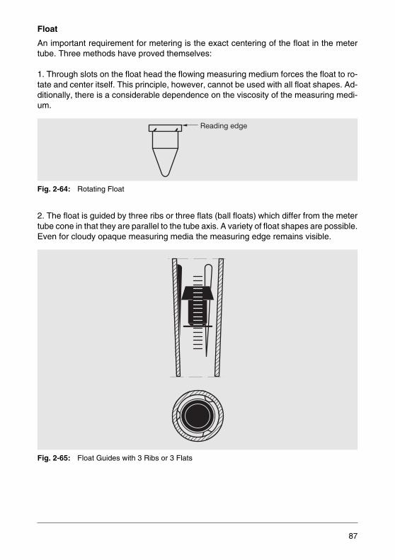
Float
An important requirement for metering is the exact centering of the float in the metertube. Three methods have proved themselves:
1. Through slots on the float head the flowing measuring medium forces the float to ro-tate and center itself. This principle, however, cannot be used with all float shapes. Ad-ditionally, there is a considerable dependence on the viscosity of the measuring medi-um.
Fig. 2-64: Rotating Float
2. The float is guided by three ribs or three flats (ball floats) which differ from the metertube cone in that they are parallel to the tube axis. A variety of float shapes are possible.Even for cloudy opaque measuring media the measuring edge remains visible.
Fig. 2-65: Float Guides with 3 Ribs or 3 Flats
Reading edge
87
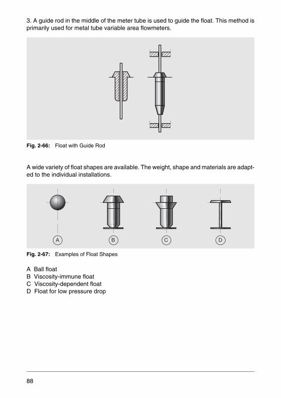
3. A guide rod in the middle of the meter tube is used to guide the float. This method isprimarily used for metal tube variable area flowmeters.
Fig. 2-66: Float with Guide Rod
A wide variety of float shapes are available. The weight, shape and materials are adapt-ed to the individual installations.
Fig. 2-67: Examples of Float Shapes
A Ball floatB Viscosity-immune float C Viscosity-dependent floatD Float for low pressure drop
A B C D
88

The ball float is the measuring element preferably used for purgemeters. Its weight canbe determined by selecting from a variety of materials. Shape changes are not possi-ble.
Therefore the flow coefficient is defined. The ball shape is responsible for the viscosityeffect.
Fig. 2-68: Viscosity Effects for the Various Float Shapes
Fig. 2-68 illustrates the effect of viscosity on the flow rate indication. The curve for theball float (1) stands out in particular because there is no linear region. That means thatevery change in viscosity results in indication changes. Remember, that for many fluidssmall changes in temperature can result in viscosity changes.
The float with the cone directed downward (Fig. 2-64 and Fig. 2-67c) is used rather inlarger sized variable area flowmeters than in small ones. The linear region of the curvein Fig. 2-68/2 is relatively small. This confirms the statement made about the rotatingfloats. Appreciably more insensitive is the float shape shown in Fig. 2-67b. The corre-sponding curve in Fig. 2-68/3 has a long linear region. Such a device is unaffected byrelatively large changes in viscosity, however, for the same size meter, 25% less flowrate can be metered than for the previously described float. The majority of the variableare flowmeters manufactured by ABB include a viscosity-immune float.
Finally there are the very light floats (Fig. 2-67d) with relatively low pressure drops. Thisdesign requires minimum upstream pressures and is usually preferred for gas flowmeasurement.
1
2
3 3 Viscosity immunefloat
2 Float with downwardoriented cone
1 Ball float
Flow
rat
e[q
v]
Viscosity [ ]ν
89
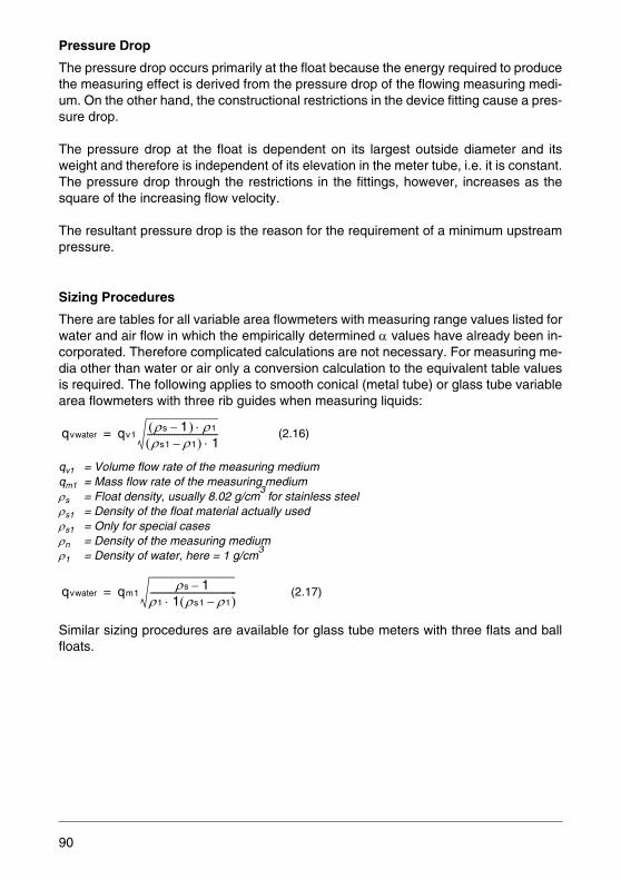
Pressure Drop
The pressure drop occurs primarily at the float because the energy required to producethe measuring effect is derived from the pressure drop of the flowing measuring medi-um. On the other hand, the constructional restrictions in the device fitting cause a pres-sure drop.
The pressure drop at the float is dependent on its largest outside diameter and itsweight and therefore is independent of its elevation in the meter tube, i.e. it is constant.The pressure drop through the restrictions in the fittings, however, increases as thesquare of the increasing flow velocity.
The resultant pressure drop is the reason for the requirement of a minimum upstreampressure.
Sizing Procedures
There are tables for all variable area flowmeters with measuring range values listed forwater and air flow in which the empirically determined α values have already been in-corporated. Therefore complicated calculations are not necessary. For measuring me-dia other than water or air only a conversion calculation to the equivalent table valuesis required. The following applies to smooth conical (metal tube) or glass tube variablearea flowmeters with three rib guides when measuring liquids:
qv1 = Volume flow rate of the measuring mediumqm1 = Mass flow rate of the measuring mediumρs = Float density, usually 8.02 g/cm
3 for stainless steel
ρs1 = Density of the float material actually usedρs1 = Only for special casesρn = Density of the measuring mediumρ1 = Density of water, here = 1 g/cm
3
Similar sizing procedures are available for glass tube meters with three flats and ballfloats.
(2.16)
(2.17)
qvwater qv1ρs 1–( ) ρ1⋅ρs1 ρ1–( ) 1⋅
--------------------------------=
qvwater qm1ρs 1–
ρ1 1 ρs1 ρ1–( )⋅---------------------------------------=
90

Example:
It is necessary to calculate the gas density ρB relative to air before converting to equiv-alent table values for air:
ρn = Density of gas at normal conditionsTn = 273.15 KT = [°C]pn = 1.013 bar p = [bar] ρ1 = Density of gas at operating conditions
Equation 2.16 can be simplified for gases (ρs << ρw; ρs1 << ρ1) to:
Measuring medium Ammonia, liquidMass flow rate qm 1500 kg/h
Density ρ 0.68 kg/l
Dyn. viscosity η 0.23 mPas
Operating pressure 15 bar Operating temperature 20 °C
From equation (2.17):
l/h
This water equivalent value is used in the tables for the selecteddevice to determine the meter size.
(2.18)
(2.19)
qvwater 1500 8.02 1–0.68 1 8.02 0.68–( )⋅------------------------------------------------------=
qvwater 1779=
ρnAir 1.293 [kg / m3]=
ρBρn
1.293--------------- Tn
Tn T+---------------- pn p+
pn---------------⋅ ⋅=
qv( )n qv1ρs ρ1⋅ρs1 ρn⋅------------------=
91

Use this equation and the dimensionless ratio to calculate the ρs for the air table values:
or for the mass flow rate qm:
Example:
Viscosity Effects
After selection of the flow meter size the viscosity effects should be checked using theviscosity influence value, VUZ:
η = Current viscosity value of the measuring medium.
(2.20)
(2.21)
Measuring medium Ammonia, gaseous Flow rate qm 1500 kg/l
Density ρn 0.7714 kg/m3 Pressure p 5 bar
Temperature T 100 °C
from equations (2.18) and (2.19):
(2.22)
qv( )nAir qv1ρs ρB⋅
ρs1----------------=
qv( )nAirqm1
1.293--------------- ρs
ρs1 ρB⋅-------------------⋅=
ρB0.77141.293
------------------ 273373---------- 6.013
1.013--------------- 2.592=⋅ ⋅=
qv( )nAir15001.293--------------- 8.02
8.02 2.592⋅------------------------------- 720.6 m3/h=⋅=
VUZ η ρs ρw–ρs1 ρ1–( )ρ1 ρw⋅
------------------------------------------ η ρ1 1–ρs1 ρ1–( )ρ1
-------------------------------= =
92

The calculated viscosity influence value must be smaller than the value listed in the flowrate tables.The flow rates are unaffected by viscosities less than the calculated valueeven when the viscosity changes. If the calculated viscosity influence value exceedsthe listed values, then the device must be calibrated using the current viscosity.
Example:
Variable area flowmeters can be selected and exactly calculated in a much simpler wayusing the ABB calculation software “flow calc”.
Device Selection
A typical range of variable are flowmeter products includes a metal tube and a glasstube line that are used for the most different applications:
Fig. 2-69: Comparison of Metal Tube and Glass Tube VA Flowmeters
Measuring medium Ammonia Dyn. viscosity η 0.23 m · Pas
Density ρ 0.68 kg/l
Float density ρs = ρs1 8.02 (stainless steel)
In the table a viscosity influence value of 28 is specified; the calculated value is much smaller. There is no viscosity effect.
VUZ 0.23 8.02 1–(8.02 0.68) 0.68⋅–------------------------------------------------- 0.27= =
Metal tube Glass tube
• High pressure and temperature conditions
• Opaque measuring media
• Steam applications• High flow rate• Current and contact
outputs• HART communication• Digital display
• Low-cost solution
• Visual check of measuring medium
• Extremely low pressure conditions
• Clear, transparent measuring medium
93

Device Description of Purgemeters
Purgemeters are built small and designed for small flow rates with local indication. Allare designed so that the meter tubes can be exchanged and include a needle valve toset the flow rate. The span is 1:10 or 1:12.5 for scale lengths between 38 and 250 mm.A ball float is used. The accuracy is a function of the meter tube material and the scalelength.
For water, or equivalently calculated other liquids, the upper range value is between0.03 l/h and 140 l/h, for air and gases it is between 2.88 and 4330 l/h.
“SNAP-IN” Purgemaster Series FAG6100
"SNAP-IN" is an elegant method for exchanging meter tubes. The meter tube holderand seals in the upper fitting are spring loaded so that the meter tube can be pushedup and pulled out towards the bottom. A polycarbonate protection cap locks the metertube in place. An integrated non-return valve prevents reverse flow. A DVGW certificatehas been granted.
Fig. 2-70: FAG6100 Series
Materials
HousingMeter tube holderMeter tubeFloatO-ringsProtection cap
Stainless steel1.4401 brassBorosilicate glass, TrogamidGlass, sapphire, tantalum, 1.4401, CarboloyBuna N, Viton A, ethylene-propylenePolycarbonate
FAG6100-31 withdifferential pressure regulator
FAG6100-32
94
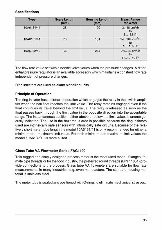
Specifications
The flow rate value set with a needle valve varies when the pressure changes. A differ-ential pressure regulator is an available accessory which maintains a constant flow rateindependent of pressure changes.
Ring initiators are used as alarm signalling units.
Principle of Operation
The ring initiator has a bistable operation which engages the relay in the switch ampli-fier when the ball float reaches the limit value. The relay remains engaged even if thefloat continues its travel beyond the limit value. The relay is released as soon as thefloat passes back through the limit value in the opposite direction into the acceptablerange. The instantaneous position, either above or below the limit value, is unambigu-ously indicated. The use in the hazardous area is possible because the ring initiatorsused are intrinsically safe sensors with intrinsically safe circuits. Because of the rela-tively short meter tube length the model 10A6131/41 is only recommended for either aminimum or a maximum limit value. For both minimum and maximum limit values themodel 10A6132/42 is more suited.
Glass Tube VA Flowmeter Series FAG1190
This rugged and simply designed process meter is the most used model. Flanges, fe-male pipe threads or for the food industry, the preferred round threads (DIN 11851) pro-vide connections to the process. Glass tube VA flowmeters are suitable for flow ratemeasurements in many industries, e.g. oven manufacture. The standard housing ma-terial is stainless steel.
The meter tube is sealed and positioned with O-rings to eliminate mechanical stresses.
Type Scale Length(mm)
Housing Length(mm)
Meas. Rangefor Water
10A6134/44 38 120 3...48 cm3/hto
3...132 l/h
10A6131/41 70 151 24...264 cm3/hto
10...105 l/h
10A6132/42 130 264 2.6...32 cm3/hto
11.2...140 l/h
95
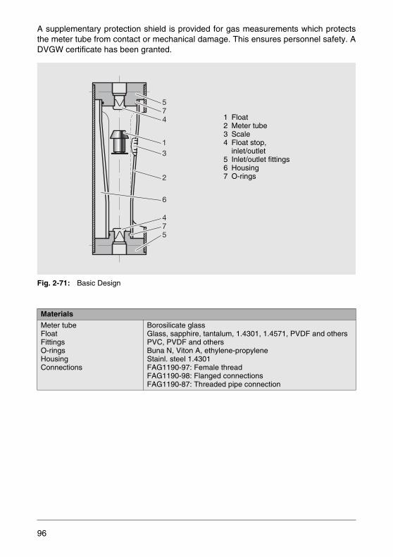
A supplementary protection shield is provided for gas measurements which protectsthe meter tube from contact or mechanical damage. This ensures personnel safety. ADVGW certificate has been granted.
Fig. 2-71: Basic Design
Materials
Meter tubeFloatFittingsO-ringsHousingConnections
Borosilicate glassGlass, sapphire, tantalum, 1.4301, 1.4571, PVDF and othersPVC, PVDF and othersBuna N, Viton A, ethylene-propyleneStainl. steel 1.4301FAG1190-97: Female threadFAG1190-98: Flanged connectionsFAG1190-87: Threaded pipe connection
574
574
13
2
6
1 Float2 Meter tube3 Scale4 Float stop,
inlet/outlet5 Inlet/outlet fittings6 Housing7 O-rings
96
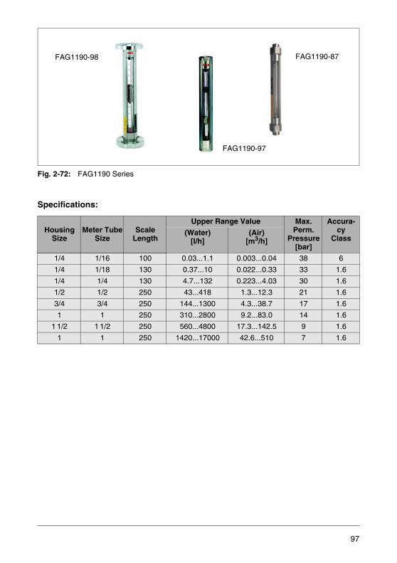
Fig. 2-72: FAG1190 Series
Specifications:
HousingSize
Meter TubeSize
ScaleLength
Upper Range Value Max. Perm.
Pressure[bar]
Accura-cy
Class(Water)
[l/h](Air)
[m3/h]
1/4 1/16 100 0.03...1.1 0.003...0.04 38 6
1/4 1/18 130 0.37...10 0.022...0.33 33 1.6
1/4 1/4 130 4.7...132 0.223...4.03 30 1.6
1/2 1/2 250 43...418 1.3...12.3 21 1.6
3/4 3/4 250 144...1300 4.3...38.7 17 1.6
1 1 250 310...2800 9.2...83.0 14 1.6
1 1/2 1 1/2 250 560...4800 17.3...142.5 9 1.6
1 1 250 1420...17000 42.6...510 7 1.6
FAG1190-98
FAG1190-97
FAG1190-87
97
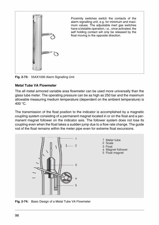
Fig. 2-73: 55AX1000 Alarm Signalling Unit
Metal Tube VA Flowmeter
The all metal armored variable area flowmeter can be used more universally than theglass tube meter. The operating pressure can be as high as 250 bar and the maximumallowable measuring medium temperature (dependent on the ambient temperature) is400 °C.
The transmission of the float position to the indicator is accomplished by a magneticcoupling system consisting of a permanent magnet located in or on the float and a per-manent magnet follower on the indicator axis. The follower system does not lose itscoupling even when the float takes a sudden jump due to a flow rate change. The guiderod of the float remains within the meter pipe even for extreme float excursions.
Fig. 2-74: Basic Design of a Metal Tube VA Flowmeter
Proximity switches switch the contacts of thealarm signalling unit, e.g. for minimum and maxi-mum values. The adjustable inert gas switcheshave a bistable operation, i.e., once activated, theself holding contact will only be released by thefloat moving in the opposite direction.
N
S
N
S
N S
1
2
3
4
5
2 Scale
4 Magnet follower5 Float magnet
3 Float
1 Meter tube
98
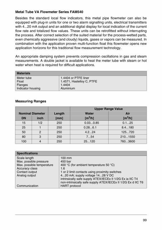
Metal Tube VA Flowmeter Series FAM540
Besides the standard local flow indicators, this metal pipe flowmeter can also beequipped with plug-in units for one or two alarm signalling units, electrical transmitterswith 4...20 mA output and an additional digital display for local indication of the currentflow rate and totalized flow values. These units can be retrofitted without interruptingthe process. After correct selection of the suited material for the process-wetted parts,even chemically aggressive (and cloudy) liquids, gases or vapors can be measured. Incombination with the application proven multi-function float this flowmeter opens newapplication horizons for this traditional flow measurement technology.
An appropriate damping system prevents compression oscillations in gas and steammeasurements. A double jacket is available to heat the meter tube with steam or hotwater when heat is required for difficult applications.
Measuring Ranges
Materials
Meter tubeFloatFlangesIndicator housing
1.4404 or PTFE liner1.4571, Hastelloy C, PTFE1.4404Aluminium
Upper Range Value
Nominal Diameter Length Water Air
DN inch [mm] [m3/h] [m3/h]
15 1/2 250 0.03...0.85 0.1...25
25 1 250 0.28...6.1 8.4...180
50 2 250 4.2...24 125...720
80 3 250 7...54 210...1550
100 4 250 25...120 760...3600
Specifications
Scale lengthMax. possible pressureMax. possible temperatureAccuracy classContact outputAnalog output
Communication
100 mm450 bar400 °C (for ambient temperature 50 °C)1.61 or 2 limit contacts using proximity switches4...20 mA; supply voltage 14...28 V DCintrinsically safe supply ATEX/IECEx II 1/2G Ex ia IIC T4non-intrinsically safe supply ATEX/IECEx II 1/2G Ex d IIC T6HART protocol
99

Electrical Transmitter
All metal tube flowmeters with transmitters are designed so that the mechanical indica-tor will continue to operate even if the transmitter should fail. This means that the mea-sured value can always be read at the meter location even if the transmission of theelectrical signals has been interrupted.
The transmitter is a two-wire device. It allows to access and change all measuring pa-rameters if required.
The transmitter monitors itself and includes automatic error diagnostics. Three pro-gramming switches are accessible when the cover is removed. It is also possible toconfigure the transmitter through magnetic pen operation without opening the cover. Ahigh-contrast two-line LCD display is provided for viewing the measured values and pa-rameters.
Fig. 2-75: Metal Tube VA Flowmeter Series FAM540
FAM541Standard design
FAM544Hygienic design
FAM545PTFE-lined
FAM546Heat jacket design
For universal application
For food and bever-age/pharmaceutical applications
For aggres-sive media
For temperature-sensitive processes
100

Armored Purgemeter Series FAM3200
This small variable area flowmeter in an all-metal design allows to readily measure theflow rate of gases and liquids under extreme conditions. Cloudy liquids, which are com-mon in the chemical, petrochemical and pharmaceutical industries, present no prob-lems to this flowmeter.
Even in the laboratory, for gas analyzers and wherever the prevailing conditions ex-clude the use of a glass tube meter, the advantages of the small armored purgemetercome to the fore.
Fig. 2-76: Design Types Section View
Materials
Medium-wetted partsO-ringsIndicator housingCap
1.4571, PVDFViton A, Buna NAluminium, stainless steelPolycarbonate, Trogamid, stainless steel with glass window
Specifications
Min. meas. range
Max. meas. range
Scale lengthMax. perm. pressureMax. perm. temperatureAccuracy classAnalog outputContact output
0.1...1.0 l/h water0.008...0.048 m3/h air300...3000 l/h water8...90 m3/h air60 mm100 bar150 °C64...20 mA1 or 2 limit values using proximity switches
FAM3200-25
FAM3200-25
FAM3200-20
101

2.2.6 Electromagnetic Flowmeters
If an electrical conductor is moved in a magnetic field which is perpendicular to the di-rection of motion and to the conductor, an electrical voltage is induced in the conductorwhose magnitude is proportional to the magnetic field strength and the velocity of themovement. This characterization of the laws of induction also applies to the movementof a conductive liquid in a pipe through a magnetic field.
Fig. 2-77: Operating Principle of an Electromagnetic Flowmeter
For the resulting electromagnetic flowmeter the following equation applies:
with the induction B, the flow velocity v and the conductor length (pipe diameter) D.
The flow rate qv through the cross section A under consideration is
Combining the two equations results in the defining relationship for the measuring sys-tem:
(2.23)
(2.24)
UE
y
z
x
BD
E
v
Magnet coil
Meter tube inelectrode plane
Measuring electrode
Measuring voltage
Uo B v D⋅ ⋅∼
qv A v D2π4
---------- v⋅=⋅=
Uo qv∼
102
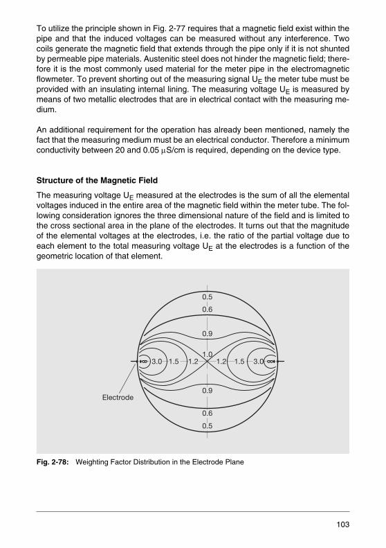
To utilize the principle shown in Fig. 2-77 requires that a magnetic field exist within thepipe and that the induced voltages can be measured without any interference. Twocoils generate the magnetic field that extends through the pipe only if it is not shuntedby permeable pipe materials. Austenitic steel does not hinder the magnetic field; there-fore it is the most commonly used material for the meter pipe in the electromagneticflowmeter. To prevent shorting out of the measuring signal UE the meter tube must beprovided with an insulating internal lining. The measuring voltage UE is measured bymeans of two metallic electrodes that are in electrical contact with the measuring me-dium.
An additional requirement for the operation has already been mentioned, namely thefact that the measuring medium must be an electrical conductor. Therefore a minimumconductivity between 20 and 0.05 μS/cm is required, depending on the device type.
Structure of the Magnetic Field
The measuring voltage UE measured at the electrodes is the sum of all the elementalvoltages induced in the entire area of the magnetic field within the meter tube. The fol-lowing consideration ignores the three dimensional nature of the field and is limited tothe cross sectional area in the plane of the electrodes. It turns out that the magnitudeof the elemental voltages at the electrodes, i.e. the ratio of the partial voltage due toeach element to the total measuring voltage UE at the electrodes is a function of thegeometric location of that element.
Fig. 2-78: Weighting Factor Distribution in the Electrode Plane
Electrode
0.5
0.5
0.6
0.6
0.9
1.0
0.9
1.21.53.0 1.2 1.5 3.0
103
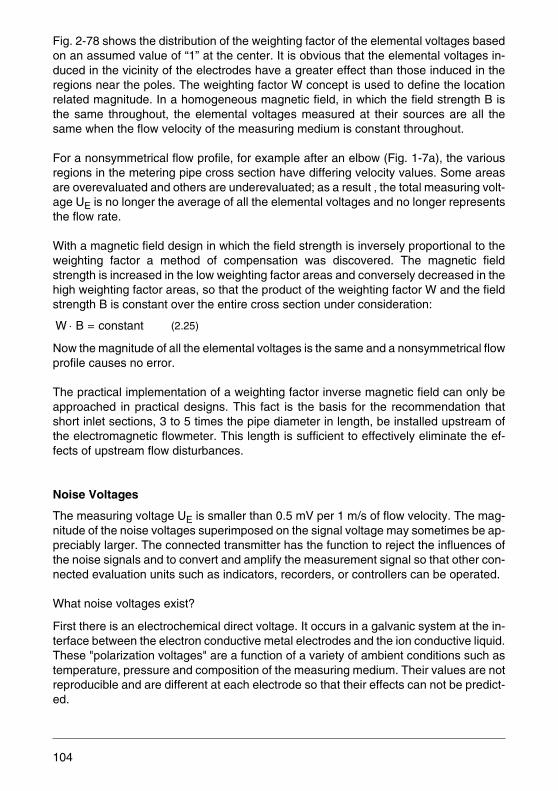
Fig. 2-78 shows the distribution of the weighting factor of the elemental voltages basedon an assumed value of “1” at the center. It is obvious that the elemental voltages in-duced in the vicinity of the electrodes have a greater effect than those induced in theregions near the poles. The weighting factor W concept is used to define the locationrelated magnitude. In a homogeneous magnetic field, in which the field strength B isthe same throughout, the elemental voltages measured at their sources are all thesame when the flow velocity of the measuring medium is constant throughout.
For a nonsymmetrical flow profile, for example after an elbow (Fig. 1-7a), the variousregions in the metering pipe cross section have differing velocity values. Some areasare overevaluated and others are underevaluated; as a result , the total measuring volt-age UE is no longer the average of all the elemental voltages and no longer representsthe flow rate.
With a magnetic field design in which the field strength is inversely proportional to theweighting factor a method of compensation was discovered. The magnetic fieldstrength is increased in the low weighting factor areas and conversely decreased in thehigh weighting factor areas, so that the product of the weighting factor W and the fieldstrength B is constant over the entire cross section under consideration:
Now the magnitude of all the elemental voltages is the same and a nonsymmetrical flowprofile causes no error.
The practical implementation of a weighting factor inverse magnetic field can only beapproached in practical designs. This fact is the basis for the recommendation thatshort inlet sections, 3 to 5 times the pipe diameter in length, be installed upstream ofthe electromagnetic flowmeter. This length is sufficient to effectively eliminate the ef-fects of upstream flow disturbances.
Noise Voltages
The measuring voltage UE is smaller than 0.5 mV per 1 m/s of flow velocity. The mag-nitude of the noise voltages superimposed on the signal voltage may sometimes be ap-preciably larger. The connected transmitter has the function to reject the influences ofthe noise signals and to convert and amplify the measurement signal so that other con-nected evaluation units such as indicators, recorders, or controllers can be operated.
What noise voltages exist?
First there is an electrochemical direct voltage. It occurs in a galvanic system at the in-terface between the electron conductive metal electrodes and the ion conductive liquid.These "polarization voltages" are a function of a variety of ambient conditions such astemperature, pressure and composition of the measuring medium. Their values are notreproducible and are different at each electrode so that their effects can not be predict-ed.
(2.25)W B constant=⋅
104

The magnetic coils are capacitively coupled to the signal lines and to the electrodes in-side the flowmeter sensor. This coupled “capacitive noise” voltage is a function of theexcitation voltage and of the internal impedance of the measuring section and is there-fore also a function of the conductivity of the measuring medium. Careful shieldingmeasures, especially when the conductivity is low, can prevent stray capacitance influ-ences.
The signal lines in the device are the connection elements coming from the electrodesand are brought together at the top of the metering pipe and together with the measur-ing medium form a single turn loop in which the excitation circuit induces a “transformervoltage”.
Precise mechanical assembly and orderly placement of the lines minimize this voltage.Liquid filled flowmeters, particularly in the larger sizes, are good conductors of groundcurrents from a nonsymmetrical electrical distribution system.
Fig. 2-79: Conductive Loop in a Transformer
The voltage differential existing between the electrodes due to these currents inducesan additional “external” noise voltage, which can be prevented by shunting the groundcurrent around the meter. This can be achieved through a parallel connected low resis-tance grounded conductor (large copper wire).
To reduce the noise voltages various means are employed which are a function of thedifferent types of magnetic field excitation to prevent either their generation or their ef-fects. Direct current voltages, e.g. polarization voltages, can be blocked by capacitivelycoupling to the transmitter.
105
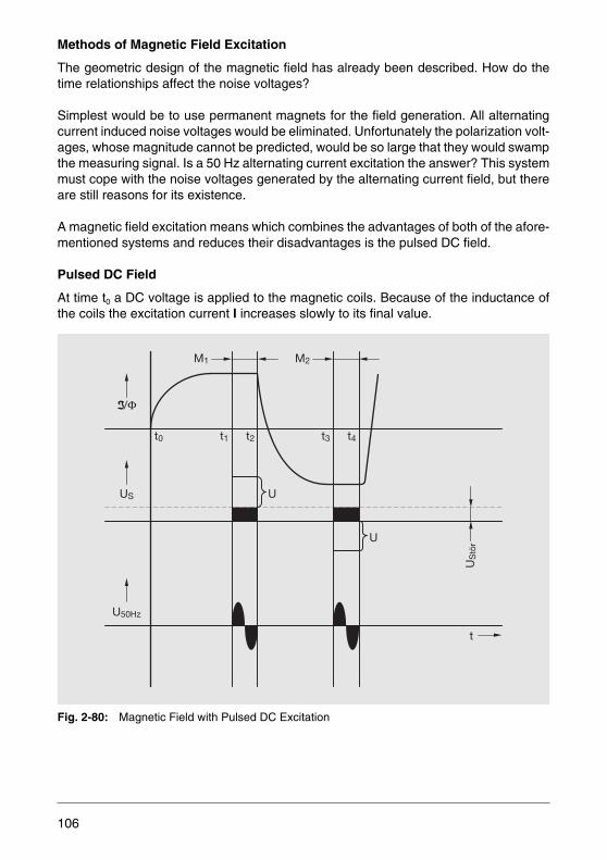
Methods of Magnetic Field Excitation
The geometric design of the magnetic field has already been described. How do thetime relationships affect the noise voltages?
Simplest would be to use permanent magnets for the field generation. All alternatingcurrent induced noise voltages would be eliminated. Unfortunately the polarization volt-ages, whose magnitude cannot be predicted, would be so large that they would swampthe measuring signal. Is a 50 Hz alternating current excitation the answer? This systemmust cope with the noise voltages generated by the alternating current field, but thereare still reasons for its existence.
A magnetic field excitation means which combines the advantages of both of the afore-mentioned systems and reduces their disadvantages is the pulsed DC field.
Pulsed DC Field
At time t0 a DC voltage is applied to the magnetic coils. Because of the inductance ofthe coils the excitation current I increases slowly to its final value.
Fig. 2-80: Magnetic Field with Pulsed DC Excitation
US U
t0 t1 t2 t3 t4
U50Hz
t
U
M1 M2
US
tör
106
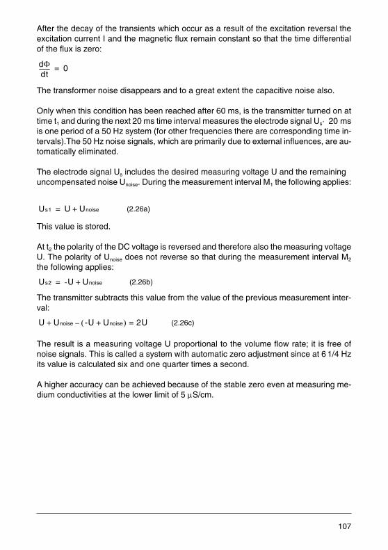
After the decay of the transients which occur as a result of the excitation reversal theexcitation current I and the magnetic flux remain constant so that the time differentialof the flux is zero:
The transformer noise disappears and to a great extent the capacitive noise also.
Only when this condition has been reached after 60 ms, is the transmitter turned on attime t1 and during the next 20 ms time interval measures the electrode signal Us· 20 msis one period of a 50 Hz system (for other frequencies there are corresponding time in-tervals).The 50 Hz noise signals, which are primarily due to external influences, are au-tomatically eliminated.
The electrode signal Us includes the desired measuring voltage U and the remaininguncompensated noise Unoise. During the measurement interval M1 the following applies:
This value is stored.
At t2 the polarity of the DC voltage is reversed and therefore also the measuring voltageU. The polarity of Unoise does not reverse so that during the measurement interval M2
the following applies:
The transmitter subtracts this value from the value of the previous measurement inter-val:
The result is a measuring voltage U proportional to the volume flow rate; it is free ofnoise signals. This is called a system with automatic zero adjustment since at 6 1/4 Hzits value is calculated six and one quarter times a second.
A higher accuracy can be achieved because of the stable zero even at measuring me-dium conductivities at the lower limit of 5 μS/cm.
(2.26a)
(2.26b)
(2.26c)
dΦdt-------- 0=
Us1 U Unoise+=
Us2 -U Unoise+=
U Unoise -U Unoise+( ) 2U=–+
107
AC Magnetic Field
The pulsed DC field has some limitations when a fast measurement is required and the160 ms measurement cycle is too long.
An example is the filling technology in which extremely short measurement intervalsare coupled with exact valve closure characteristics. Another application is the mea-surement of two-phase media, i.e. the hydraulic transport of solids like, for example,paper pulp or dredged material. With direct current excitation these measuring mediagenerate a noise voltage that is superimposed on the measuring signal and results inerrors. These noise voltages do not occur with alternating current excitation.
The field excitation is provided directly from the mains voltage (e.g. 50 or 60 Hz) or froma driver circuit in the transmitter. Due to the high inductance of the magnetic coils, themagnetic flux Φ lags to the excitation current I by almost 90°.
The measuring voltage U is in phase with Φ, i.e. it is a sinusoidal voltage at mains fre-quency whose amplitude is proportional to the flow rate. The various noise voltages arefed together with the signal voltages to the connected transmitter which must sort themout accordingly.
The DC noise voltages (polarization voltages) are capacitively decoupled. The ACnoise voltages (transformer and capacitive voltages) are not in phase with the measur-ing voltage U. Their effects are automatically compensated using phase selective cir-cuits.
Unfortunately, the amplitude or phase of the external AC noise voltages cannot be pre-dicted. All components that are not in phase with the measuring voltage U are automat-ically compensated. Only the in-phase component affects the measuring signal, result-ing in an unstable zero. This noise component is eliminated by static compensation ofthe measured values that exist at zero flow.
The zero adjustment can be automated when a defined zero flow occurs during themeasurement. This is, for example, the case in filling processes. When the closed shut-off valve signals a “stand-still”, the transmitter receives the command for zero correc-tion. AC field excitation allows for a minimum conductivity of the measuring mediumdown to 20 μS/cm. This conductivity limit can be reduced to 0.5 μS/cm with an imped-ance converter. Continued development of this technology has resulted in a driver cir-cuit which will provide an excitation current at a frequency considerably higher than thenormal line frequency of 50 or 60 Hz. Using this technology, mains frequency inducednoise components can be automatically compensated and the zero stability is almostas accurate as when a pulsed DC excitation is used.
108
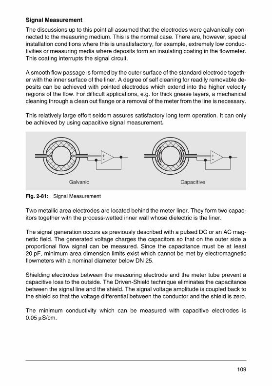
Signal Measurement
The discussions up to this point all assumed that the electrodes were galvanically con-nected to the measuring medium. This is the normal case. There are, however, specialinstallation conditions where this is unsatisfactory, for example, extremely low conduc-tivities or measuring media where deposits form an insulating coating in the flowmeter.This coating interrupts the signal circuit.
A smooth flow passage is formed by the outer surface of the standard electrode togeth-er with the inner surface of the liner. A degree of self cleaning for readily removable de-posits can be achieved with pointed electrodes which extend into the higher velocityregions of the flow. For difficult applications, e.g. for thick grease layers, a mechanicalcleaning through a clean out flange or a removal of the meter from the line is necessary.
This relatively large effort seldom assures satisfactory long term operation. It can onlybe achieved by using capacitive signal measurement.
Fig. 2-81: Signal Measurement
Two metallic area electrodes are located behind the meter liner. They form two capac-itors together with the process-wetted inner wall whose dielectric is the liner.
The signal generation occurs as previously described with a pulsed DC or an AC mag-netic field. The generated voltage charges the capacitors so that on the outer side aproportional flow signal can be measured. Since the capacitance must be at least20 pF, minimum area dimension limits exist which cannot be met by electromagneticflowmeters with a nominal diameter below DN 25.
Shielding electrodes between the measuring electrode and the meter tube prevent acapacitive loss to the outside. The Driven-Shield technique eliminates the capacitancebetween the signal line and the shield. The signal voltage amplitude is coupled back tothe shield so that the voltage differential between the conductor and the shield is zero.
The minimum conductivity which can be measured with capacitive electrodes is0.05 μS/cm.
+-
+-
CapacitiveGalvanic
109
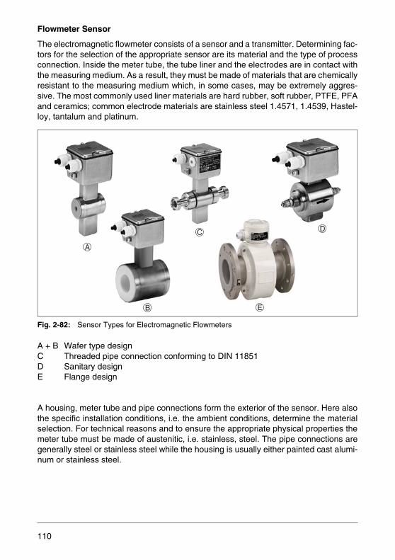
Flowmeter Sensor
The electromagnetic flowmeter consists of a sensor and a transmitter. Determining fac-tors for the selection of the appropriate sensor are its material and the type of processconnection. Inside the meter tube, the tube liner and the electrodes are in contact withthe measuring medium. As a result, they must be made of materials that are chemicallyresistant to the measuring medium which, in some cases, may be extremely aggres-sive. The most commonly used liner materials are hard rubber, soft rubber, PTFE, PFAand ceramics; common electrode materials are stainless steel 1.4571, 1.4539, Hastel-loy, tantalum and platinum.
Fig. 2-82: Sensor Types for Electromagnetic Flowmeters
A + B Wafer type designC Threaded pipe connection conforming to DIN 11851 D Sanitary designE Flange design
A housing, meter tube and pipe connections form the exterior of the sensor. Here alsothe specific installation conditions, i.e. the ambient conditions, determine the materialselection. For technical reasons and to ensure the appropriate physical properties themeter tube must be made of austenitic, i.e. stainless, steel. The pipe connections aregenerally steel or stainless steel while the housing is usually either painted cast alumi-num or stainless steel.
A
B
C D
E
110
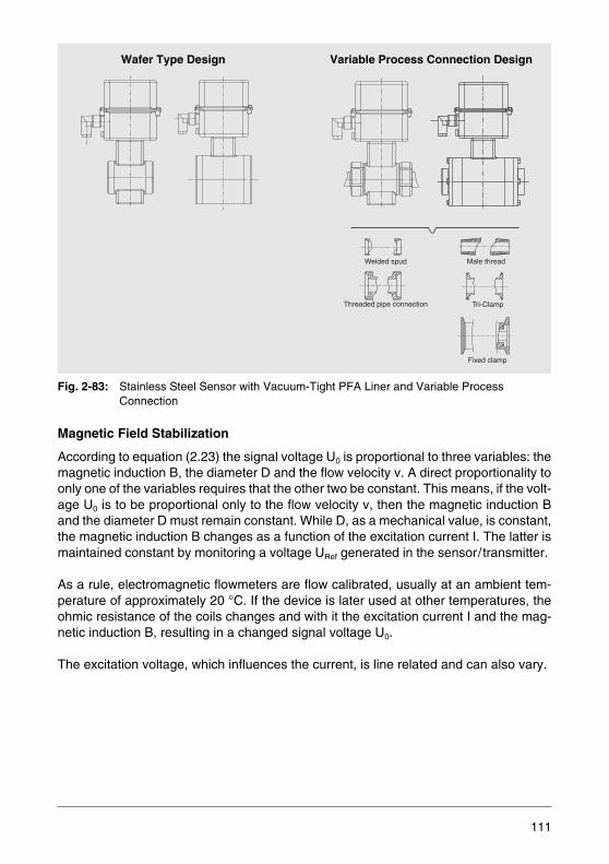
Fig. 2-83: Stainless Steel Sensor with Vacuum-Tight PFA Liner and Variable Process Connection
Magnetic Field Stabilization
According to equation (2.23) the signal voltage U0 is proportional to three variables: themagnetic induction B, the diameter D and the flow velocity v. A direct proportionality toonly one of the variables requires that the other two be constant. This means, if the volt-age U0 is to be proportional only to the flow velocity v, then the magnetic induction Band the diameter D must remain constant. While D, as a mechanical value, is constant,the magnetic induction B changes as a function of the excitation current I. The latter ismaintained constant by monitoring a voltage URef generated in the sensor/transmitter.
As a rule, electromagnetic flowmeters are flow calibrated, usually at an ambient tem-perature of approximately 20 °C. If the device is later used at other temperatures, theohmic resistance of the coils changes and with it the excitation current I and the mag-netic induction B, resulting in a changed signal voltage U0.
The excitation voltage, which influences the current, is line related and can also vary.
Welded spud
Threaded pipe connection Tri-Clamp
Male thread
Fixed clamp
Wafer Type Design Variable Process Connection Design
111
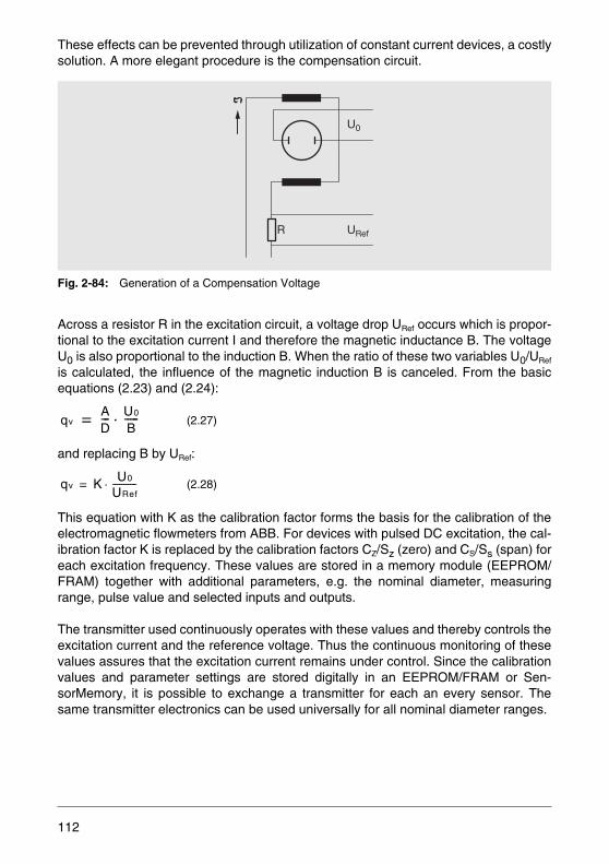
These effects can be prevented through utilization of constant current devices, a costlysolution. A more elegant procedure is the compensation circuit.
Fig. 2-84: Generation of a Compensation Voltage
Across a resistor R in the excitation circuit, a voltage drop URef occurs which is propor-tional to the excitation current I and therefore the magnetic inductance B. The voltageU0 is also proportional to the induction B. When the ratio of these two variables U0/URef
is calculated, the influence of the magnetic induction B is canceled. From the basicequations (2.23) and (2.24):
and replacing B by URef:
This equation with K as the calibration factor forms the basis for the calibration of theelectromagnetic flowmeters from ABB. For devices with pulsed DC excitation, the cal-ibration factor K is replaced by the calibration factors CZ/Sz (zero) and CS/Ss (span) foreach excitation frequency. These values are stored in a memory module (EEPROM/FRAM) together with additional parameters, e.g. the nominal diameter, measuringrange, pulse value and selected inputs and outputs.
The transmitter used continuously operates with these values and thereby controls theexcitation current and the reference voltage. Thus the continuous monitoring of thesevalues assures that the excitation current remains under control. Since the calibrationvalues and parameter settings are stored digitally in an EEPROM/FRAM or Sen-sorMemory, it is possible to exchange a transmitter for each an every sensor. Thesame transmitter electronics can be used universally for all nominal diameter ranges.
(2.27)
(2.28)
U0
URefR
qvAD--- U0
B-----⋅=
qv K U0
URef-----------⋅=
112
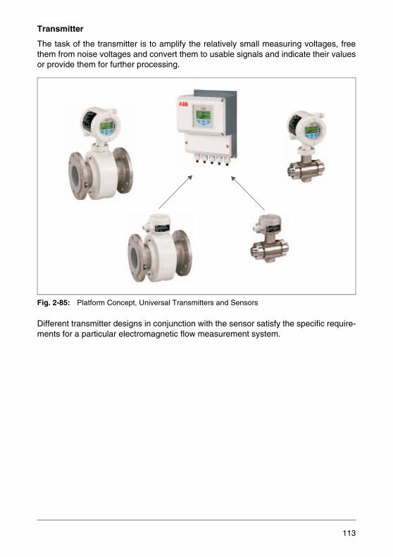
Transmitter
The task of the transmitter is to amplify the relatively small measuring voltages, freethem from noise voltages and convert them to usable signals and indicate their valuesor provide them for further processing.
Fig. 2-85: Platform Concept, Universal Transmitters and Sensors
Different transmitter designs in conjunction with the sensor satisfy the specific require-ments for a particular electromagnetic flow measurement system.
113
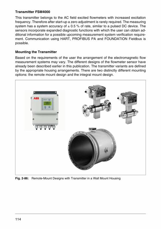
Transmitter FSM4000
This transmitter belongs to the AC field excited flowmeters with increased excitationfrequency. Therefore after start-up a zero adjustment is rarely required. The measuringsystem has a system accuracy of ± 0.5 % of rate, similar to a pulsed DC device. Thesensors incorporate expanded diagnostic functions with which the user can obtain ad-ditional information for a possible upcoming measurement system verification require-ment. Communication using HART, PROFIBUS PA and FOUNDATION Fieldbus ispossible.
Mounting the Transmitter
Based on the requirements of the user the arrangement of the electromagnetic flowmeasurement systems may vary. The different designs of the flowmeter sensor havealready been described earlier in this publication. The transmitter variants are definedby the appropriate housing arrangements. There are two distinctly different mountingoptions: the remote mount design and the integral mount design.
Fig. 2-86: Remote-Mount Designs with Transmitter in a Wall Mount Housing
114
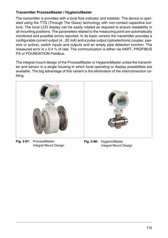
Transmitter ProcessMaster / HygienicMaster
The transmitter is provided with a local flow indicator and totalizer. The device is oper-ated using the TTG (Through The Glass) technology with non-contact capacitive but-tons. The local LCD display can be easily rotated as required to ensure readability inall mounting positions. The parameters related to the measuring point are automaticallymonitored and possible errors reported. In its basic version the transmitter provides aconfigurable current output (4...20 mA) and a pulse output (optoelectronic coupler, pas-sive or active), switch inputs and outputs and an empty pipe detection function. Themeasured error is ± 0.4 % of rate. The communication is either via HART, PROFIBUSPA or FOUNDATION Fieldbus.
The integral mount design of the ProcessMaster or HygienicMaster unites the transmit-ter and sensor in a single housing in which local operating or display possibilities areavailable. The big advantage of this variant is the elimination of the interconnection ca-bling.
Fig. 2-87: ProcessMasterIntegral Mount Design
Fig. 2-88: HygienicMasterIntegral Mount Design
115
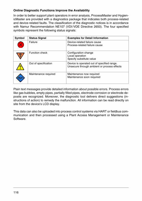
Online Diagnostic Functions Improve the Availability
In order to better support plant operators in error analysis, ProcessMaster and Hygien-icMaster are provided with a diagnostics package that indicates both process-relatedand device-related faults. The classification of the diagnostic notices is in accordancewith Namur Recommendation NE107 (VDI/VDE Directive 2650). The four specifiedsymbols represent the following status signals:
Plain text messages provide detailed information about possible errors. Process errorslike gas bubbles, empty pipes, partially filled pipes, electrode corrosion or electrode de-posits are recognized. Moreover, the diagnostic tool delivers direct suggestions (in-structions of action) to remedy the malfunction. All information can be read directly onsite from the device's LCD display.
This data can also be uploaded into process control systems via HART or fieldbus com-munication and then processed using a Plant Access Management or MaintenanceSoftware.
Symbol Status Signal Examples for Detail Information
Failure Device-related failure causeProcess-related failure cause
Function check Configuration changeLocal operationSpecify substitute value
Out of specification Device is operated out of specified range.Unsecure through ambient or process effects
Maintenance required Maintenance now requiredMaintenance soon required
116

Verification of Built-In Devices
ScanMaster is a DTM-based verification tool for checking the functionality and integrityof the transmitters and sensors of built-in ProcessMaster or HygienicMaster flowme-ters. Gradual changes like electrode deposits are logged by ProcessMaster orHygienicMaster 500 as trend data and can be read out and represented graphically byScanMaster. The tool provides any easy method for cyclic verification of all measuredvalues and of the functional reliability of the installed devices.The determined test andverification results are stored in a database and can be retrieved and printed as re-quired.
Fig. 2-89: SanMaster FZC500 Diagnostic and Verification Software
117
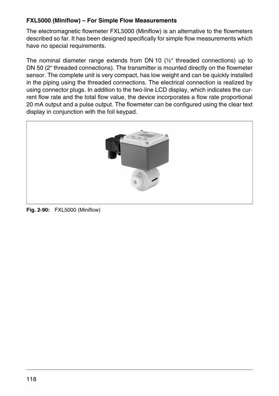
FXL5000 (Miniflow) – For Simple Flow Measurements
The electromagnetic flowmeter FXL5000 (Miniflow) is an alternative to the flowmetersdescribed so far. It has been designed specifically for simple flow measurements whichhave no special requirements.
The nominal diameter range extends from DN 10 (½“ threaded connections) up toDN 50 (2“ threaded connections). The transmitter is mounted directly on the flowmetersensor. The complete unit is very compact, has low weight and can be quickly installedin the piping using the threaded connections. The electrical connection is realized byusing connector plugs. In addition to the two-line LCD display, which indicates the cur-rent flow rate and the total flow value, the device incorporates a flow rate proportional20 mA output and a pulse output. The flowmeter can be configured using the clear textdisplay in conjunction with the foil keypad.
Fig. 2-90: FXL5000 (Miniflow)
118

FES7000 (Fill-MAG) – For Filling and Dosing Applications
Exact filling and dosing with high reproducibility often presents difficulties in conjunctionwith small but also with very large containers. These problems have been addressedand solved by ABB with an electromagnetic flowmeter based solution: FES7000 (Fill-MAG) and FXF2000 (COPA-XF).
Depending on the individual application requirements (measuring medium, fill and dos-ing time, boundary conditions, etc.) it is also possible to use mass, vortex and swirlflowmeters for batch processes. The control technology for mass flowmeters offers thesame comfort as an FES7000 system (for more detailed information about these de-vices see the corresponding device descriptions).
The FES7000 provides a very compact and intelligent electromagnetic flowmeter sys-tem whose major features are a fast response time and specialized software adaptedto batch and fill processes coupled with an ability to CIP/SIP clean the abrasion resis-tant sensor. This specialized software allows for filling and dosing processes with mea-surement periods ≥ 500 ms and assures a reproducibility of ≤ 0.2 % of rate. In a fill sys-tem the automatic measurement and correction of the second stage flow, which is afunction of the valve characteristics, is of great importance. Good and reproduciblemeasurement results can only be achieved with systems such as the FES7000, whichcan compensate for these effects and is suitable for a variety of diverse boundary con-ditions.
Flowmeter Technology
The FES7000 is a system with remote mount design. The transmitter is available as a19" plug-in unit and in a field housing. The process connection options for the stainlesssteel flowmeter sensor include all the usual commercially available connections. Cus-tomer-specific design variants are also possible.
The FES7000 system operates with defined input and output contacts (Fig. 2-91). Fourdifferent fill and preset volumes can be set directly at the transmitter or selected by anexternal fill volume selector switch or from a PC, PLC or distributed control system.
The fill cycle is initiated by a start signal which opens the valve. After the anticipatoryor end contact volumes have been reached the transmitter directly controls the fillvalve. Up to 32 transmitters can be connected using the RS 485 interface and config-ured via an operator station, PLC or transmitter dialog unit. The connection of additionalcomponents such as control loops, control elements (weigh scale) as well as printersis possible.
119
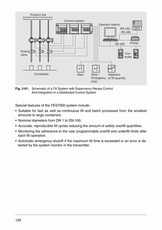
Fig. 2-91: Schematic of a Fill System with Supervisory Recipe ControlAnd Integration in a Distributed Control System
Special features of the FES7000 system include:
• Suitable for fast as well as continuous fill and batch processes from the smallestamounts to large containers.
• Nominal diameters from DN 1 to DN 100.
• Accurate, reproducible fill cycles reducing the amount of safety overfill quantities.
• Monitoring the adherence to the user programmable overfill and underfill limits aftereach fill operation.
• Automatic emergency shutoff if the maximum fill time is exceeded or an error is de-tected by the system monitor in the transmitter.
Containers
Dosingvalve
Product line
Operator stationSPS
PrinterRS 485
RS 232 /RS 485
Con-troller
Selectionof fill quantity
Stop /Emergencystop
Start
Control system
120
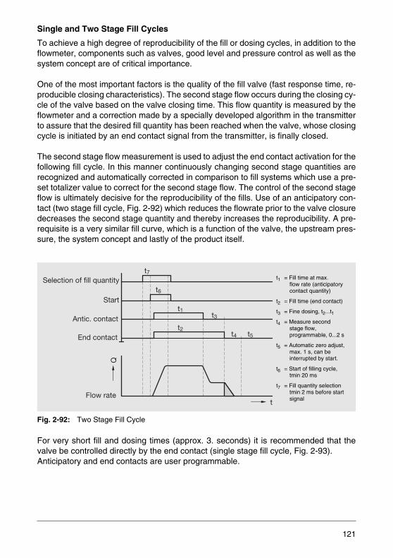
Single and Two Stage Fill Cycles
To achieve a high degree of reproducibility of the fill or dosing cycles, in addition to theflowmeter, components such as valves, good level and pressure control as well as thesystem concept are of critical importance.
One of the most important factors is the quality of the fill valve (fast response time, re-producible closing characteristics). The second stage flow occurs during the closing cy-cle of the valve based on the valve closing time. This flow quantity is measured by theflowmeter and a correction made by a specially developed algorithm in the transmitterto assure that the desired fill quantity has been reached when the valve, whose closingcycle is initiated by an end contact signal from the transmitter, is finally closed.
The second stage flow measurement is used to adjust the end contact activation for thefollowing fill cycle. In this manner continuously changing second stage quantities arerecognized and automatically corrected in comparison to fill systems which use a pre-set totalizer value to correct for the second stage flow. The control of the second stageflow is ultimately decisive for the reproducibility of the fills. Use of an anticipatory con-tact (two stage fill cycle, Fig. 2-92) which reduces the flowrate prior to the valve closuredecreases the second stage quantity and thereby increases the reproducibility. A pre-requisite is a very similar fill curve, which is a function of the valve, the upstream pres-sure, the system concept and lastly of the product itself.
Fig. 2-92: Two Stage Fill Cycle
For very short fill and dosing times (approx. 3. seconds) it is recommended that thevalve be controlled directly by the end contact (single stage fill cycle, Fig. 2-93). Anticipatory and end contacts are user programmable.
t7
t6
t1t3
t4 t5t2
t
Q
Flow rate
End contact
Antic. contact
Start
Selection of fill quantity t1 = Fill time at max. flow rate (anticipatory contact quantity)
t2 = Fill time (end contact)
t3 = Fine dosing, t2...t1
t4 = Measure secondstage flow,programmable, 0...2 s
t5 = Automatic zero adjust,max. 1 s, can beinterrupted by start.
t6 = Start of filling cycle,tmin 20 ms
t7 = Fill quantity selectiontmin 2 ms before start signal
121
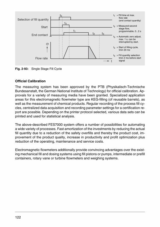
Fig. 2-93: Single Stage Fill Cycle
Official Calibration
The measuring system has been approved by the PTB (Physikalisch-TechnischeBundesanstalt, the German National Institute of Technology) for official calibration. Ap-provals for a variety of measuring media have been granted. Specialized applicationareas for this electromagnetic flowmeter type are KEG-filling (of reusable barrels), aswell as the measurement of chemical products. Regular recording of the process fill cy-cles, centralized data acquisition and recording parameter settings for a certification re-port are possible. Depending on the printer protocol selected, various data sets can beprinted and used for statistical analysis.
The above-described FES7000 system offers a number of possibilities for automatinga wide variety of processes. Fast amortization of the investments by reducing the actualfill quantity due to a reduction of the safety overfills and thereby the product cost, im-provement of the product quality, increase in productivity and profit optimization plusreduction of the operating, maintenance and service costs.
Electromagnetic flowmeters additionally provide convincing advantages over the exist-ing mechanical fill and dosing systems using fill pistons or pumps, intermediate or prefillcontainers, rotary vane or turbine flowmeters and weighing systems.
t5
t4
t2 t3t1
t
Q
Flow rate
End contact
Start
Selection of fill quantity
t1 = Fill time at max. flow rate(end contact quantity)
t2 = Measured secondstage flow,programmable, 0...2 s
t3 = Automatic zero adjust,max. 1 s, can beinterrupted by start.
t4 = Start of filling cycle,tmin 20 ms
t5 = Fill quantity selectiontmin 2 ms before startsignal
122
Advantages include:
• Wear-free system requiring low maintenance.
• CIP/SIP capability of the flowmeter reducing the cleaning and sterilization time.
• Shortest fill times for a variety of fill quantities possible because of the wide rangespan.
• Higher product output through optimal utilization of the system, because suctionphase and tare determination required by mechanical systems are eliminated.
• Communication possible with the measurement system including integrated statisti-cal functions.
FXF2000 (COPA-XF) – For Simple Filling and Dosing Applications
This flowmeter with integral mount design is an all stainless steel device. Due its smalldimensions it is ideal for cluster mounting in round and series filling machines.It is alsosuitable for continuous flow measurement, when only a pulse or current output is re-quired and display is not required for indication. The reproducibility of the device is0.2 % of rate for fill cycles longer than 2...4 seconds.
The flowmeter is available with nominal diameters from DN 3 to DN 100. All the usualcommercial process connections are available. Customer-specific connection variantsare also possible. For harsh operating conditions the FXF2000 includes an instrumentair connection for creating a protective air stream. The device is also available in a trop-icalized design with coated circuit boards.
The FXF2000 incorporates three different operating modes. In addition to the “Batch”operating mode for fill and dosing processes with a function as flow rate proportionalsensor and a pulse output, the “Conti” operating mode for continuous measurementwith an additional 0/4...20 mA current output is available. The “Filler” operating modeincludes the function as a stand-alone fill system and is mainly based on the FES7000technology described above.
As the FXF2000 basic functions just include a pure flowmeter functionality with fre-quency or current output and a standardized pulse output, additional hardware andsoftware are required for realizing fill and dosing processes. Value-loaded pulses mustbe totalized and processed using a presetting counter, PC, PLC or DCS.
123

Fill quantity preselection, utilization of single or two stage fill system, start/stop function,second stage flow measurement and correction, control and/or monitoring functions aswell as valve actuation are all functions which must be carried out by other evaluationelectronics connected to the flow rate sensor. These electronics or software have a tre-mendous effect on the quality of a fill and dosing system and the reproducibility of thefill processes. Fig. 2-96 shows a schematic of such a filling system.
Fig. 2-94: Flowmeter FXF2000 (COPA-XF)
Decisive for the development of such a device were the market demands for an eco-nomical, small and effective compact electromagnetic flowmeter in an integral mountstainless steel design for multivalve fillers with up to 168 fill valves.
Due the impressive number of fill valves per system and the possibility to develop andconfigure the required software in-house, this system concept became interesting fromtechnical and economic viewpoints.
One time developed software together with know-how can be transferred to many othersystems. Each system type can utilize the economical standard flowmeters, but is pro-vided with individually adapted software with different user interfaces and system-spe-cific components.
Fig. 2-95: Flowmeter FXF2000 (COPA-XF) with Integral Mount Design and Communication Capabilities
124
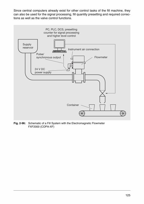
Since central computers already exist for other control tasks of the fill machine, theycan also be used for the signal processing, fill quantity presetting and required correc-tions as well as the valve control functions.
Fig. 2-96: Schematic of a Fill System with the Electromagnetic FlowmeterFXF2000 (COPA-XF)
PC, PLC, DCS, presettingcounter for signal processing
and higher level control
Supplyreservoir
Flowmeter
Instrument air connection
Container
24 V DCpower supply
Pulse/synchronous output
125

Communication Capabilities
For the configuration and control of the device two possibilities are available. If the de-vice requires service, a transmitter control unit with display can be plugged on.
If parameter changes for the process or information about the present status of the pro-cess is required the RS 485 interface can be used.
The ASCII Protocol allows for communication with a distributed control system, a pro-grammable logic controller or a PC with the required individual software. The connec-tion is made using a separate communication plug.
A complete solution including the monitoring of the flowmeter and parameter settingwithout the need to open the housing is provided by a dialog unit with integral display.
This new generation of volumetric operating fill machines with electromagnetic flowmeasurements instead of fill systems with intermediate or preset fill containers (limita-tions for fluid varieties and fill time) or weigh systems, takes advantage of the manybenefits which an electromagnetic flow measurement system offers. The CIP/SIP-cleanability, wear free and low maintenance technology, viscosity insensitivity coupledwith the wide span of the electromagnetic flowmeter with a simple and fast change overto other fill quantities results in quality improvements, product savings by reducingoverfills, productivity improvement and cost reductions.
126
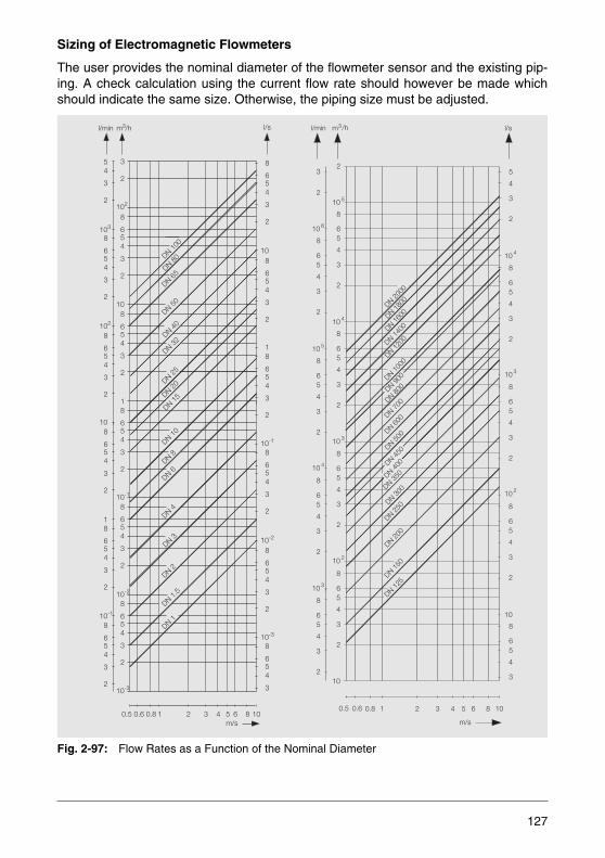
Sizing of Electromagnetic Flowmeters
The user provides the nominal diameter of the flowmeter sensor and the existing pip-ing. A check calculation using the current flow rate should however be made whichshould indicate the same size. Otherwise, the piping size must be adjusted.
Fig. 2-97: Flow Rates as a Function of the Nominal Diameter
l/min l/s3/hm
54
3
2
103
102
8
654
3
2
8
654
3
2
10-1
108
654
3
8
654
3
2
2
1
8
654
3
2
8
654
3
2
8
654
3
2
8
654
3
10-1
10-2
10-3
108
654
3
2
18
654
3
2
8
654
3
2
DN 100
DN 80
DN 65
DN 50
DN 40
DN 32
DN 25
DN 20
DN 15
DN 10
DN 8
DN 6
DN 4
DN 3
DN 2
DN 1.5
DN 1
32 4 5 6 8 1010.60.5m/s
10-3
10-1
10-2
8
654
3
2
8
654
3
2
8
654
3
2
1
108
654
3
2
102
8
654
3
2
3
2
0.8
5
4
3
2
10 4
8
65
4
3
2
10 3
8
65
4
3
2
10 2
8
65
4
3
2
8
65
4
3
10
3
2
8
65
4
3
2
8
65
4
3
2
8
65
4
3
2
8
65
4
3
2
l/min m3/h l/s
m/s
2 3 4 5 6 8 100.5 0.6 0.8 1
2
10 5
10 3
8
65
4
3
2
10 4
8
65
4
3
2
10 2
8
65
4
3
2
10
8
65
4
3
2
DN50
0DN60
0DN70
0DN80
0DN90
0DN10
00
DN16
00
DN12
00DN14
00
DN18
00DN20
00
DN12
5
DN15
0
DN20
0
DN25
0DN30
0DN35
0
10 6
10 5
10 4
10 3
DN 450
DN 400
127
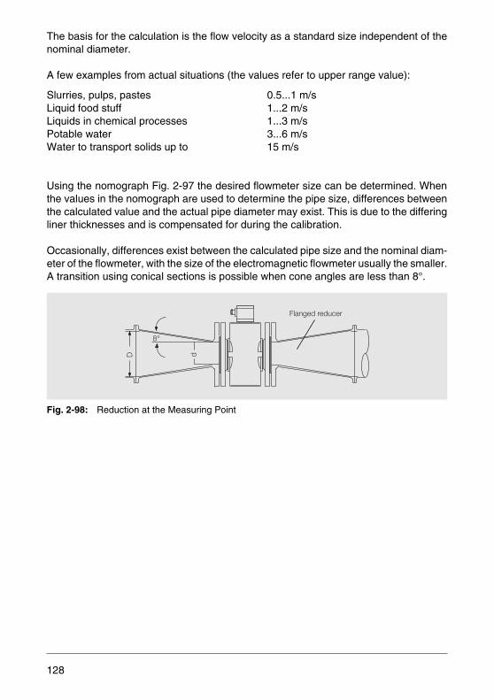
The basis for the calculation is the flow velocity as a standard size independent of thenominal diameter.
A few examples from actual situations (the values refer to upper range value):
Slurries, pulps, pastes 0.5...1 m/sLiquid food stuff 1...2 m/sLiquids in chemical processes 1...3 m/sPotable water 3...6 m/sWater to transport solids up to 15 m/s
Using the nomograph Fig. 2-97 the desired flowmeter size can be determined. Whenthe values in the nomograph are used to determine the pipe size, differences betweenthe calculated value and the actual pipe diameter may exist. This is due to the differingliner thicknesses and is compensated for during the calibration.
Occasionally, differences exist between the calculated pipe size and the nominal diam-eter of the flowmeter, with the size of the electromagnetic flowmeter usually the smaller.A transition using conical sections is possible when cone angles are less than 8°.
Fig. 2-98: Reduction at the Measuring Point
D d
8°
Flanged reducer
128

The pressure drop resulting from the 8° reduction can be calculated using the nomo-graph Fig. 2-99. For this the diameter ratio d/D must be calculated and the curve for thecurrent flow velocity v selected from the family of curves. The pressure drop Δp can beread at the intersection between these two values.
Fig. 2-99: Pressure Drop with Pipe Restriction
10
1
0.5 0.6 0.7 0.8 0.9
→ Diameter ratio d/D
v=8m/s
7m/s
6m/s
5m/s
4m/s
3m/s
2m/s
1m/s
100
→P
ress
ure
drop
Δp[m
bar]
129

Specifications
Tab. 2-5: Overview of Flowmeter Sensor and Transmitter Designs
Signal Measurement Galvanic
Magn. Field Excit. With Pulsed DC Excitation
Model ProcessMaster FEP300/500HygienicMaster FEH300/500
FXF2000 (COPA-XF)
Liner material DN PN DN PN Hard rubber 15...2000 10...100 Cl150...Cl600Soft rubber 50...2000 10...40 CL150/CL300Ceramic carbide 25...1000 10...40 CL150/CL300PTFE 10...600 10...40 CL150/CL300ETFE 25...1000 10...40 CL150/CL300PFA 3...200 10...40 CL150/CL300 3...100 10...40Peek 1...2 10
Electrode material Stainl. steel 1.4571 or 1.4539, Hastelloy C4 or B2, titanium, tantalum, platinum-iridium
Excitation frequency 6 1/4 Hz, 12 1/2 Hz or 25 Hz 12.5/25 Hz
Min. conductivity 5 μS/cm 5 μS/cm
Max. poss. pressure rat-ing
PN 100/Cl600 and higher PN 40/Cl300
Max. poss. temperature 180 °C 130 °C (150 °C)
Electrode design Standard electrode, pointed electrode
Process connection Flange DN 3...2000Wafer design DN 3...100Welded spud DN 3...100Threaded pipe conn. DN 3...100Tri-Clamp DN 3...100Male thread DN 3...251/8“ sanitary conn. DN 1...2
Wafer Des. DN 3...100Weld st. DN 3...100Thr. pipe conn. DN 3...100Tri-Clamp DN 3...100Fixed clamp DN 10...40Male thread DN 3...25
Upper range value 0.5...20 m/s 0.5...10 m/s
Max. meas.error
FEP300/FEH300: 0.4 % of rateopt. 0.2 % of rate
FEP500/FEH500: 0.3 % of rateopt. 0.2 % of rate
0.5...10 m/s0.5 % of rateReproducibility≤ 0.2 % of rate
Current output 4...20 mA, 4...12...20 mA selectable 0...5 mA, 0/2...10 mA,0/4...20 mA, 0...10...20 mA, 4...12...20 mA selectable
Load 0...600 Ω 0...600 Ω
Pulse output Passive, active Passive, active
Pulse width Selectable from 0.1 ms...2000 ms Selectable from 0.1 ms...2000 ms
Supply power Switch-mode power supply85...253 V AC16.8...26.4 V AC16.8...31.2 V DC
16.8...31.2 V DC
130
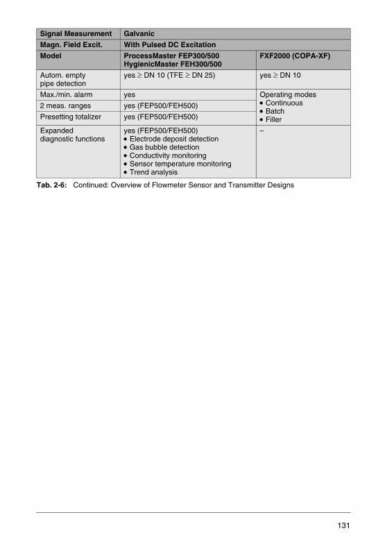
Tab. 2-6: Continued: Overview of Flowmeter Sensor and Transmitter Designs
Signal Measurement Galvanic
Magn. Field Excit. With Pulsed DC Excitation
Model ProcessMaster FEP300/500HygienicMaster FEH300/500
FXF2000 (COPA-XF)
Autom. emptypipe detection
yes ≥ DN 10 (TFE ≥ DN 25) yes ≥ DN 10
Max./min. alarm yes Operating modes• Continuous• Batch• Filler
2 meas. ranges yes (FEP500/FEH500)
Presetting totalizer yes (FEP500/FEH500)
Expandeddiagnostic functions
yes (FEP500/FEH500)• Electrode deposit detection• Gas bubble detection• Conductivity monitoring• Sensor temperature monitoring• Trend analysis
–
131
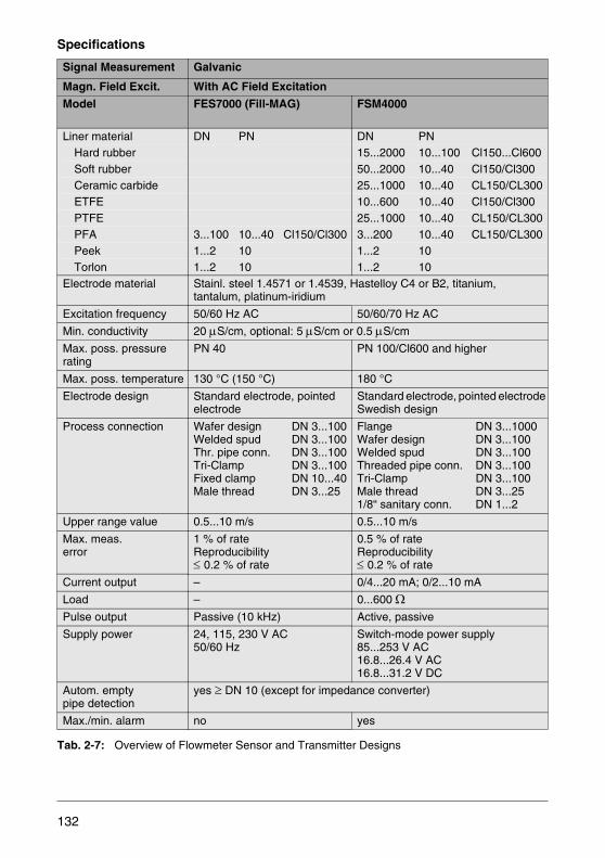
Specifications
Tab. 2-7: Overview of Flowmeter Sensor and Transmitter Designs
Signal Measurement Galvanic
Magn. Field Excit. With AC Field Excitation
Model FES7000 (Fill-MAG) FSM4000
Liner material DN PN DN PN Hard rubber 15...2000 10...100 Cl150...Cl600Soft rubber 50...2000 10...40 Cl150/Cl300Ceramic carbide 25...1000 10...40 CL150/CL300ETFE 10...600 10...40 Cl150/Cl300PTFE 25...1000 10...40 CL150/CL300PFA 3...100 10...40 Cl150/Cl300 3...200 10...40 CL150/CL300Peek 1...2 10 1...2 10Torlon 1...2 10 1...2 10
Electrode material Stainl. steel 1.4571 or 1.4539, Hastelloy C4 or B2, titanium,tantalum, platinum-iridium
Excitation frequency 50/60 Hz AC 50/60/70 Hz AC
Min. conductivity 20 μS/cm, optional: 5 μS/cm or 0.5 μS/cm
Max. poss. pressure rating
PN 40 PN 100/Cl600 and higher
Max. poss. temperature 130 °C (150 °C) 180 °C
Electrode design Standard electrode, pointed electrode
Standard electrode, pointed electrode Swedish design
Process connection Wafer design DN 3...100Welded spud DN 3...100Thr. pipe conn. DN 3...100Tri-Clamp DN 3...100Fixed clamp DN 10...40Male thread DN 3...25
Flange DN 3...1000Wafer design DN 3...100Welded spud DN 3...100Threaded pipe conn. DN 3...100Tri-Clamp DN 3...100Male thread DN 3...251/8“ sanitary conn. DN 1...2
Upper range value 0.5...10 m/s 0.5...10 m/s
Max. meas.error
1 % of rateReproducibility ≤ 0.2 % of rate
0.5 % of rateReproducibility ≤ 0.2 % of rate
Current output – 0/4...20 mA; 0/2...10 mA
Load – 0...600 Ω
Pulse output Passive (10 kHz) Active, passive
Supply power 24, 115, 230 V AC50/60 Hz
Switch-mode power supply85...253 V AC16.8...26.4 V AC16.8...31.2 V DC
Autom. empty pipe detection
yes ≥ DN 10 (except for impedance converter)
Max./min. alarm no yes
132

WaterMaster – For Water Applications
WaterMaster provides the flexibility to solve your most demanding water applications,enabling previously unattainable operational and financial benefits. WaterMaster is theultimate solution for flow measurement and management in sectors as diverse as wa-ter, wastewater, sewage and effluent. Innovative and versatile attributes allow toachieve interoperability within a wide range of asset management systems. WaterMas-ter delivers speed, simplicity and ease of use.
Advanced Sensor Design
The WaterMaster range is available in sizes DN 10 to DN 2400 (3/8 to 94 inch). Aninnovative octagonal sensor design improves the flow profile and reduces upstreamand downstream piping requirements for the most commonly installed sizes DN 40 toDN 200. Flowmeters with traditional sensor designs are used for sizes over DN 2000.Using a higher excitation frequency combined with advanced filtering, WaterMaster im-proves measurement accuracy by reducing liquid and electrode noise.
Submersible and Buriable Installation Options
All WaterMaster sensors have a rugged, robust construction to ensure a long, mainte-nance-free life under the most difficult conditions experienced in the water and wastewater industries. The sensors are, as standard, inherently submersible (IP68, NEMA6P), thus ensuring suitability for installation in chambers and metering pits which areliable to flooding. A unique feature of the WaterMaster sensors (DN 500 to DN 2400)is that they are buriable. Installation merely involves excavating to the undergroundpipe, fitting the sensor, cabling to the transmitter and then backfilling the hole.
Fig. 2-100: Electromagnetic Flowmeter WaterMaster
133
Custody Transfer
WaterMaster has an MID/OIML R49 Approval for Accuracy Classes 1 and 2 for pipingswith any mounting position and bidirectional flow. A water meter with MID approval issuitable for billing applications. It provides a high measuring accuracy and reliable mea-sured values.
Self-Calibration
A unique self-calibration concept developed by ABB (patent pending) has been imple-mented in WaterMaster. Compliance with OIML R49 Type P (Permanent) checking re-quirements requires that electromagnetic flowmeters have 'Checking Facilities', wherea simulated signal is fed into the input of the flow transmitter and the output is comparedand checked within predetermined limits. ABB's WaterMaster has taken this to the nextlevel. It uses this signal to not only check the accuracy, but also to perform automaticcalibration. This not only meets and exceeds the OIML R49 requirements, it alsomeans the device has the following features:
• Self-calibrating device.• No factory calibration necessary.• Calibration adjustment is continuous during normal running. • Exceptional long-term stability.• Very low temperature coefficient.• Measurement accuracy depends on one precision resistor only. • Adjustment % displayed to user for diagnostic use.• Alarm limits to trap hardware failures and out-of-range adjustments
VeriMaster Insitu Verification Software
WaterMaster can be expanded with the VeriMaster software for insitu verfication. Ver-iMaster is a PC application. When the PC is coupled to the WaterMaster through theinfrared service port, it generates a report on the accuracy of the complete flowmeter,both sensor and transmitter. This technology builds on over 10 years of ABB’s experi-ence in the field of insitu verification, through its leading CalMaster range. VeriMasteris a quick and easy to use utility, that uses the advanced self-calibration and diagnosticcapability of WaterMaster, coupled with fingerprinting technology. This allows to deter-mine the accuracy status of the WaterMaster flowmeter to within +/-1 % of its originalfactory calibration. VeriMaster also supports printing of calibration verification recordsfor regulatory compliance.
134

VeriMaster integrates with WaterMaster seamlessly, meaning:
• No interruption to any of the wiring.• No cover removal, with operation through the front glass using the infrared service
port. • No interruption to the measurement.
If desired, an operator can additionally check and record the accuracy of the currentand pulse outputs.
Improved Results through Digital Signal Processing
Digital Signal Processing (DSP) gives improved performance and enables real timemeasurements for maximum reliability. DSP allows the transmitter to separate the realsignal from the noise, thereby providing high quality outputs especially in harsh envi-ronments involving vibration, hydraulic noise and temperature fluctuation.
Speed, Ease and Security in the Field
Data storage in the WaterMaster using the “SensorMemory” principle eliminates theneed to match sensor and transmitter in the field. On initial installation, the self-config-uration sequence automatically replicates into the transmitter all calibration factors,nominal diameter and serial numbers as well as customer site specific settings. Thiseliminates the opportunity for errors and leads to increased speed of start-up. Redun-dant storage of data in both the sensor and transmitter memory is continually updatedduring all operations to ensure total integrity of the measurement. The on-board “Sen-sorMemory” eliminates the possible problems associated with pluggable data memorymodules. Easy access to wiring also minimizes the time for problem solving in the field.
Detailed Diagnostics for Rapid Decision Making
WaterMaster is proven to be robust and reliable, with unmatched diagnostic capabili-ties providing the right information to keep the process up and running. In accordancewith NAMUR NE107, alarms and warnings are classified as “maintenance required”,“function check”, “failure” and “outside of specification”.
135

AquaProbe – The Insertion Flowmeter
AquaProbe insertion flowmeters are used for clean water flow measurement. Compat-ible with ABB´s AquaMaster 3 and WaterMaster transmitters, the latest generationAquaProbe opens up new possibilities for both temporary and permanent installations.Supply options like battery, solar or wind power also makes AquaProbe ideal for use inchallenging locations.
AquaProbe can be fitted without interruption to the flow, even when the piping is underpressure. Contrary to full-bore electromagnetic flowmeters, the AquaProbe's magneticfield does not reside in the entire pipe cross-section. The flow velocity is only measuredat a representative point of the pipe section and then the flow rate is calculated fromthis in the transmitter. The accuracy of 2 % of rate is also assured for low flows. Withthis, AquaProbe is also suited for leakage monitoring in drinking water networks.
The ½“ connector on the sensor permits to connect a pressure transmitter to theAquaProbe, to provide pressure measurement capabilities in addition to flow measure-ment. In drinking water networks these two measured values (pressure and flow rate)allow to draw conclusions regarding the degree of incrustations/deposits in the piping.This is especially important for fire extinguishing pipe systems where incrustations ordeposits may affect the water throughput and, thus, cause danger in the event of a fire.
Fig. 2-101: AquaProbe system for permanent or temporary installations
136
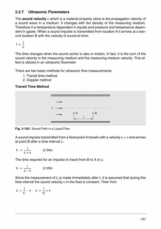
2.2.7 Ultrasonic Flowmeters
The sound velocity c which is a material property value is the propagation velocity ofa sound wave in a medium. It changes with the density of the measuring medium.Therefore it is temperature dependent in liquids and pressure and temperature depen-dent in gases. When a sound impulse is transmitted from location A it arrives at a sec-ond location B with the velocity of sound at time:
The time changes when the sound carrier is also in motion, in fact, it is the sum of thesound velocity in the measuring medium and the measuring medium velocity. This ef-fect is utilized in an ultrasonic flowmeter.
There are two basic methods for ultrasonic flow measurements:
1. Transit time method2. Doppler method
Transit Time Method
Fig. 2-102: Sound Path in a Liquid Flow
A sound impulse transmitted from a fixed point A travels with a velocity c + v and arrivesat point B after a time interval t1:
The time required for an impulse to travel from B to A is t2:
Since the measurement of t2 is made immediately after t1 it is assumed that during thistime interval the sound velocity c in the fluid is constant. Then from
(2.29a)
(2.29b)
t lc---=
v
lA B
t1l
c v+------------=
t2l
c v–------------=
c lt1---- v–= c l
t2---- v+=
137
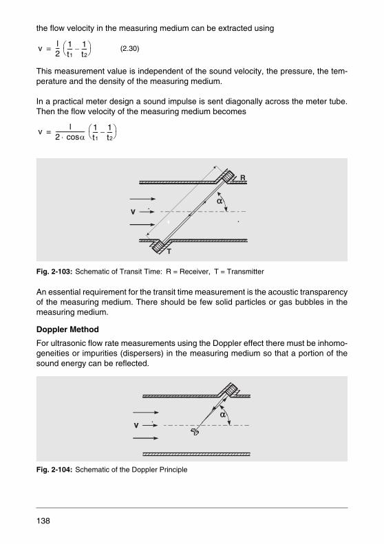
the flow velocity in the measuring medium can be extracted using
This measurement value is independent of the sound velocity, the pressure, the tem-perature and the density of the measuring medium.
In a practical meter design a sound impulse is sent diagonally across the meter tube.Then the flow velocity of the measuring medium becomes
Fig. 2-103: Schematic of Transit Time: R = Receiver, T = Transmitter
An essential requirement for the transit time measurement is the acoustic transparencyof the measuring medium. There should be few solid particles or gas bubbles in themeasuring medium.
Doppler Method
For ultrasonic flow rate measurements using the Doppler effect there must be inhomo-geneities or impurities (dispersers) in the measuring medium so that a portion of thesound energy can be reflected.
Fig. 2-104: Schematic of the Doppler Principle
(2.30)v l2--- 1
t1---- 1
t2----–⎝ ⎠
⎛ ⎞=
v l2 αcos⋅--------------------- 1
t1---- 1
t2----–⎝ ⎠
⎛ ⎞=
R
T
138
The sound wave with a transmitter frequency f1 impinges on a particle in the measuringmedium (solid particle or gas bubble) and is reflected. Therefore every particle acts asa moving transmitter with the transmitter frequency f1. The frequency shift Δf of the re-flected signal received is a function of the flow and sound velocities:
Since the sound velocity is a function of the temperature, pressure and composition ofthe measuring medium, even small changes in these variables affect the Doppler shiftand an appropriate compensation must be provided. The solution is to include a de-fined inlet section for the ultrasound, e.g. a sound path made of resin, in which a Piezotransmitter is cast.
Applying the refractive equation of Snellius
from which
and therefore
The factor cv/cos (β) can be determined. The Doppler shift is therefore essentially in-dependent of the sound velocity in the measuring medium. Only sound velocity chang-es in the acoustic inlet section change the Doppler frequency. This change can be de-termined beforehand and compensated.
Limitations of Ultrasonic Flow Measurement
For the ultrasonic flow measurement the flow velocity is measured within the narrowband of the sound beam. The calculated flow rate through the entire pipe cross-sectionis only valid for axissymmetric flow profiles. In order to assure that these conditions ex-ist, inlet sections with a length of up to 15 x D and outlet sections of up to 10 x D arerequired. It is possible to reduce the effects of nonsymmetrical flow by using two ormore sound beams for additional profile samples.
Δƒ 2 ƒ0 α( )cos vc---⋅ ⋅=
α( )cosc
------------------ β( )coscv
------------------=
Δƒ 2 ƒ0 cos β( ) vc---⋅ ⋅=
v cv
2 ƒ0 β( )cos⋅ ⋅------------------------------------ Δƒ constant= Δƒ⋅ ⋅=
139
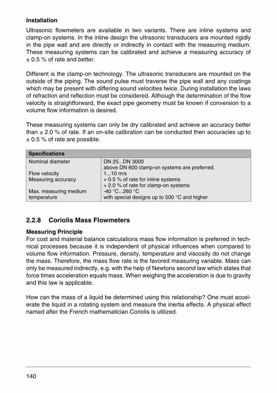
Installation
Ultrasonic flowmeters are available in two variants. There are inline systems andclamp-on systems. In the inline design the ultrasonic transducers are mounted rigidlyin the pipe wall and are directly or indirectly in contact with the measuring medium.These measuring systems can be calibrated and achieve a measuring accuracy of± 0.5 % of rate and better.
Different is the clamp-on technology. The ultrasonic transducers are mounted on theoutside of the piping. The sound pulse must traverse the pipe wall and any coatingswhich may be present with differing sound velocities twice. During installation the lawsof refraction and reflection must be considered. Although the determination of the flowvelocity is straightforward, the exact pipe geometry must be known if conversion to avolume flow information is desired.
These measuring systems can only be dry calibrated and achieve an accuracy betterthan ± 2.0 % of rate. If an on-site calibration can be conducted then accuracies up to± 0.5 % of rate are possible.
2.2.8 Coriolis Mass Flowmeters
Measuring PrincipleFor cost and material balance calculations mass flow information is preferred in tech-nical processes because it is independent of physical influences when compared tovolume flow information. Pressure, density, temperature and viscosity do not changethe mass. Therefore, the mass flow rate is the favored measuring variable. Mass canonly be measured indirectly, e.g. with the help of Newtons second law which states thatforce times acceleration equals mass. When weighing the acceleration is due to gravityand this law is applicable.
How can the mass of a liquid be determined using this relationship? One must accel-erate the liquid in a rotating system and measure the inertia effects. A physical effectnamed after the French mathematician Coriolis is utilized.
Specifications
Nominal diameter
Flow velocityMeasuring accuracy
Max. measuring medium temperature
DN 25...DN 3000above DN 600 clamp-on systems are preferred.1...10 m/s+ 0.5 % of rate for inline systems+ 2.0 % of rate for clamp-on systems-40 °C...260 °Cwith special designs up to 500 °C and higher
140
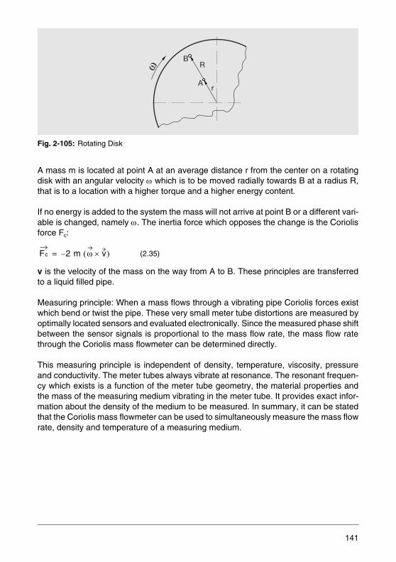
Fig. 2-105: Rotating Disk
A mass m is located at point A at an average distance r from the center on a rotatingdisk with an angular velocity ω which is to be moved radially towards B at a radius R,that is to a location with a higher torque and a higher energy content.
If no energy is added to the system the mass will not arrive at point B or a different vari-able is changed, namely ω. The inertia force which opposes the change is the Coriolisforce Fc:
v is the velocity of the mass on the way from A to B. These principles are transferredto a liquid filled pipe.
Measuring principle: When a mass flows through a vibrating pipe Coriolis forces existwhich bend or twist the pipe. These very small meter tube distortions are measured byoptimally located sensors and evaluated electronically. Since the measured phase shiftbetween the sensor signals is proportional to the mass flow rate, the mass flow ratethrough the Coriolis mass flowmeter can be determined directly.
This measuring principle is independent of density, temperature, viscosity, pressureand conductivity. The meter tubes always vibrate at resonance. The resonant frequen-cy which exists is a function of the meter tube geometry, the material properties andthe mass of the measuring medium vibrating in the meter tube. It provides exact infor-mation about the density of the medium to be measured. In summary, it can be statedthat the Coriolis mass flowmeter can be used to simultaneously measure the mass flowrate, density and temperature of a measuring medium.
(2.35)
B
A
R
r
Fc 2 m ω v×( )–=
141
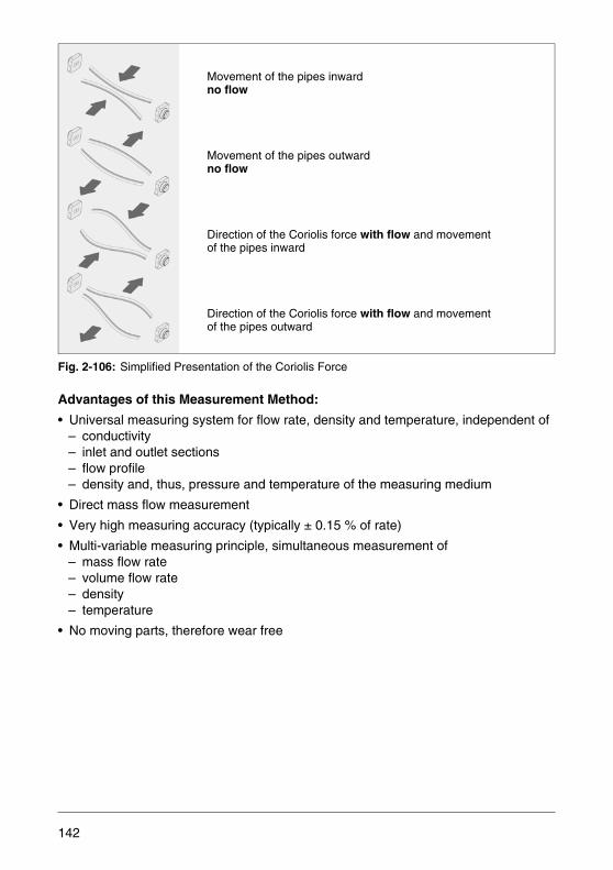
Fig. 2-106: Simplified Presentation of the Coriolis Force
Advantages of this Measurement Method:
• Universal measuring system for flow rate, density and temperature, independent of– conductivity– inlet and outlet sections– flow profile– density and, thus, pressure and temperature of the measuring medium
• Direct mass flow measurement
• Very high measuring accuracy (typically ± 0.15 % of rate)
• Multi-variable measuring principle, simultaneous measurement of– mass flow rate– volume flow rate– density– temperature
• No moving parts, therefore wear free
Movement of the pipes inwardno flow
Movement of the pipes outwardno flow
Direction of the Coriolis force with flow and movement of the pipes inward
Direction of the Coriolis force with flow and movement of the pipes outward
142
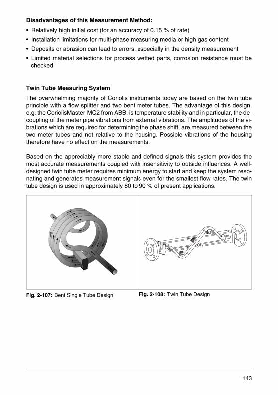
Disadvantages of this Measurement Method:
• Relatively high initial cost (for an accuracy of 0.15 % of rate)
• Installation limitations for multi-phase measuring media or high gas content
• Deposits or abrasion can lead to errors, especially in the density measurement
• Limited material selections for process wetted parts, corrosion resistance must bechecked
Twin Tube Measuring System
The overwhelming majority of Coriolis instruments today are based on the twin tubeprinciple with a flow splitter and two bent meter tubes. The advantage of this design,e.g. the CoriolisMaster-MC2 from ABB, is temperature stability and in particular, the de-coupling of the meter pipe vibrations from external vibrations. The amplitudes of the vi-brations which are required for determining the phase shift, are measured between thetwo meter tubes and not relative to the housing. Possible vibrations of the housingtherefore have no effect on the measurements.
Based on the appreciably more stable and defined signals this system provides themost accurate measurements coupled with insensitivity to outside influences. A well-designed twin tube meter requires minimum energy to start and keep the system reso-nating and generates measurement signals even for the smallest flow rates. The twintube design is used in approximately 80 to 90 % of present applications.
Fig. 2-107: Bent Single Tube Design Fig. 2-108: Twin Tube Design
143
Single Tube Measuring System
Besides the twin tube design there is also the single tube design, e.g. the ABB flowme-ter CoriolisMaster-MS2. In order to maintain the insensitivity to external vibrations, themeter tubes in this design are bent into loops. The amplitudes of the vibrations, andthereby the phase shift, are measured between the tube loops and not relative to thehousing. This principle offers distinct advantages for the smaller size meters becausea flow splitter in not required.
The straight single pipe design has advantages in that it can be more easily cleaned,has a reduced pressure drop and is less harsh on the measuring medium. However,these advantages come with a lower accuracy and a higher sensitivity to external vi-brations. Because of the straight meter tube, the amplitude differences must be mea-sured relative to the housing. If the housing is also vibrating, the effects are difficult tocompensate. Moreover, the measured signals are appreciable smaller which also con-tributes to the reduced accuracy mentioned earlier, especially for the density measure-ment.
It is difficult to start and keep a single straight tube resonating. The elasticity of a pipeis directly related to its wall thickness. Therefore vibrating straight tubes must be con-structed thin and are available only for limited nominal diameters. For abrasive or cor-rosive measuring media, however, the thin wall sections of the meter tube can add ad-ditional safety concerns.
Application Areas
Based on the advantages mentioned above it is not difficult to understand that this Co-riolis measurement principle is being preferred by more and more industries over othermeasuring principles. Of particular interest is the direct mass measurement, becausemany recipes or processes are based on the mass of the used materials. Previous de-pendence on density variations and therefore temperature or pressure changes areconcerns of the past. If in the past a volume measurement had to be converted to mass,the Coriolis technology allows to skip this step.
Since this principle is independent of the properties of the measuring medium, such asconductivity, flow profile, density, viscosity, etc., almost all materials can be measured:e.g. oils and fuels, cleaning agents and solvents, fats, silicone oil, alcohol, methane,fruit mixtures, starch, dyes, biozide, vinegar, catsup, mayonnaise, beer, milk, sugar so-lution, gases, liquefied gases, etc.
As a result of the simultaneous measurement of the density and temperature of themeasuring medium, a real time quality analysis of the medium can be made. If the den-sity of the measuring medium changes from the set point value, quality problems in theprocess are identified. Also the presence of air inclusions or similar effects can be mon-itored from the density signal.
144

In the food and beverage industry a decisive factor is the good cleanability of the instru-ments, even of a twin tube system, as the EHEDG-certified flowmeter sensor designfrom ABB has demonstrated. Furthermore the highly accurate mass and density mea-surements of the materials are a great advantage. Compositions can thus be monitoredonline. The concentrations of two phase measuring media can be determined from thedensity measurement using special software. Thus for the sugar concentration in a li-quid the °BRIX is readily available. Up to 3 different density-concentration curves canbe entered in the transmitter of the CoriolisMaster, so that every type of concentrationcan be measured.
In the chemical industry, the high-accuracy mass flow measurement is particularly im-portant. The variable explosion protection concept (Ex “e” and “i” exclusively definedby the customer's connections) including isolation and, not least, the additional securityof a flameproof enclosure around the meter tubes are also important advantages.ATEX Approvals up to Group 1 (Zone 0) have been granted. The high reproducibility(typically 0.1 % of rate) is a great advantage for control or fill processes.
In the petrochemical field the additional material compatibility per NACE and the rug-ged design are of importance, especially where extreme ambient conditions exist. Themeters are used in oil fields at -50 °C or in offshore applications where a highly corro-sive salt water environment is present. For this last application, ABB offers a specialprotective coating for the demanding North Sea applications.
In the paper industry the Coriolis mass flowmeters are predestined for use in the coat-ing and color kitchens. Problems always occurred due to the varying density of viscos-ity values; there e.g., the CoriolisMaster measures the mass directly, providing excel-lent stability and high accuracy. Also, the conversion from volume to mass flow unitshas become unnecessary.
Due to the multivariability, flexibility, high accuracy, wear resistance and ruggedness,the Coriolis mass flow measurement continues to conquer new markets and applica-tion fields. Although at first it may appear that the initial acquisition costs are higher theyoften become negligible when compared to the later savings due to more accurate andsimpler dosing. In contrast to the traditional measuring devices the measuring accuracyremains constant for a long time period at a minimum maintenance cost.
145
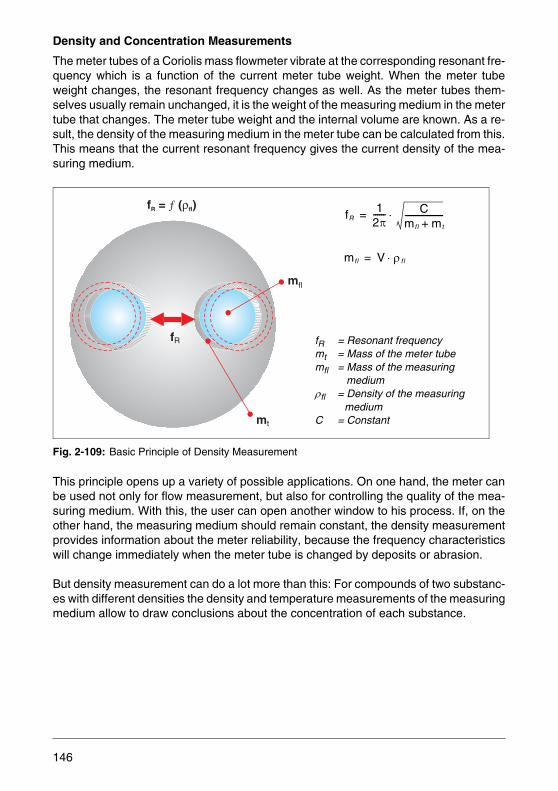
Density and Concentration Measurements
The meter tubes of a Coriolis mass flowmeter vibrate at the corresponding resonant fre-quency which is a function of the current meter tube weight. When the meter tubeweight changes, the resonant frequency changes as well. As the meter tubes them-selves usually remain unchanged, it is the weight of the measuring medium in the metertube that changes. The meter tube weight and the internal volume are known. As a re-sult, the density of the measuring medium in the meter tube can be calculated from this.This means that the current resonant frequency gives the current density of the mea-suring medium.
Fig. 2-109: Basic Principle of Density Measurement
This principle opens up a variety of possible applications. On one hand, the meter canbe used not only for flow measurement, but also for controlling the quality of the mea-suring medium. With this, the user can open another window to his process. If, on theother hand, the measuring medium should remain constant, the density measurementprovides information about the meter reliability, because the frequency characteristicswill change immediately when the meter tube is changed by deposits or abrasion.
But density measurement can do a lot more than this: For compounds of two substanc-es with different densities the density and temperature measurements of the measuringmedium allow to draw conclusions about the concentration of each substance.
mfl
mt
fR
f = ( )R flƒ ρfR
12π------ C
mf l mt+-------------------⋅=
mfl V ρf l⋅=
fR = Resonant frequencymt = Mass of the meter tubemfl = Mass of the measuring
mediumρfl = Density of the measuring
mediumC = Constant
146
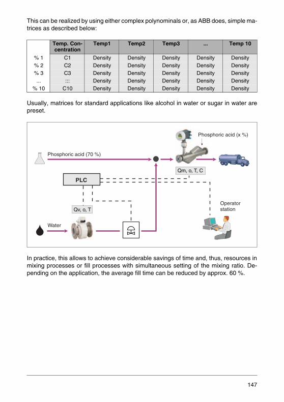
This can be realized by using either complex polynominals or, as ABB does, simple ma-trices as described below:
Usually, matrices for standard applications like alcohol in water or sugar in water arepreset.
In practice, this allows to achieve considerable savings of time and, thus, resources inmixing processes or fill processes with simultaneous setting of the mixing ratio. De-pending on the application, the average fill time can be reduced by approx. 60 %.
Temp. Con-centration
Temp1 Temp2 Temp3 ... Temp 10
% 1 C1 Density Density Density Density Density% 2 C2 Density Density Density Density Density% 3 C3 Density Density Density Density Density... ::: Density Density Density Density Density
% 10 C10 Density Density Density Density Density
�
Qm, o, T, C
Qv, o, T
Phosphoric acid (x %)
Operatorstation
Phosphoric acid (70 %)
Water
PLC
147
Frequently Asked Questions and Answers
What must be considered during the installation?These devices in comparison to the other flowmeters are relatively easy to install. Theycan be installed horizontally or vertically. Specific distances from elbows or valves, etc.are negligible because the measurements are unaffected by flow profile effects. Thedevices should be installed right before or after the flanges, but should not be attacheddirectly to the housing.
What effect do gas or air bubbles in the measuring medium have on the measurement?First gas bubbles tend to dampen the vibration of the pipes, which is compensated bya higher excitation current. If the gas content is not too large and has an essentially ho-mogeneous distribution, the mass flow measurement is hardly affected. The densitymeasurement however can be impaired. This can be explained by the measurementmethod. The resonant frequency of the vibrations is proportional the instantaneouslyvibrating mass, consisting of the measuring medium and the meter tubes. Assumingthat the tubes are completely filled, the density can be calculated from the equation:
If the pipes are not completely filled or contain a gas or air components then an errorwill occur.
How do solids affect the measurement?As long as the solids vibrate exactly the same as the meter tube and thereby add a con-tribution to the flow rate signal, there are no problems with the measurement. Decisiveis the relationship between the particle size (inertia) and the viscous forces (accelera-tion forces). The lower the viscosity the smaller the particle size should be. Generally,a self draining design is preferred, to prevent particles being deposited in the pipebends, especially when there is no flow.
What is affected if the back pressure is too low?When the back pressure is low the fullness of the meter tubes cannot be guaranteed,and also the danger that cavitation may occur exists when the vapor pressure is lessthan the system pressure.
What happens if the meter pipes are not completely filled?In this case the meter tubes cannot reach a stable vibrating condition and a measure-ment is no longer possible. This condition can be recognized by an unstable, too lowdensity signal and also by a large increase in the driver current.
m ρ V⋅=
148
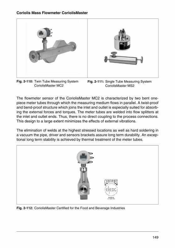
Coriolis Mass Flowmeter CoriolisMaster
Fig. 2-110: Twin Tube Measuring SystemCoriolisMaster MC2
The flowmeter sensor of the CoriolisMaster MC2 is characterized by two bent one-piece meter tubes through which the measuring medium flows in parallel. A twist-proofand bend-proof structure which joins the inlet and outlet is especially suited for absorb-ing the external forces and torques. The meter tubes are welded into flow splitters atthe inlet and outlet ends. Thus, there is no direct coupling to the process connections.This design to a large extent minimizes the effects of external vibrations.
The elimination of welds at the highest stressed locations as well as hard soldering ina vacuum the pipe, driver and sensors brackets assure long term durability. An excep-tional long term stability is achieved by thermal treatment of the meter tubes.
Fig. 2-112: CoriolisMaster Certified for the Food and Beverage Industries
Fig. 2-111: Single Tube Measuring SystemCoriolisMaster MS2
149

The optimized design of the flowmeter sensor in conjunction with the meter tube mate-rial 1.4435/316L allows unrestricted use in hygienic applications. The entire construc-tion consisting of meter tube, flow splitter and process connection has been tested andcertified per EHEDG. The CIP and SIP processes can be carried out at temperaturesup to 180 °C.
The CoriolisMaster transmitter is available in integral or remote mount design and in-corporates a digital signal processor (DSP) which allows for mass flow rate and densitymeasurements at the highest precision. An exceptional long term stability and reliabilityare the results. Self-diagnosis of the flowmeter sensor and transmitter and absolutezero stability are additional advantages.
150
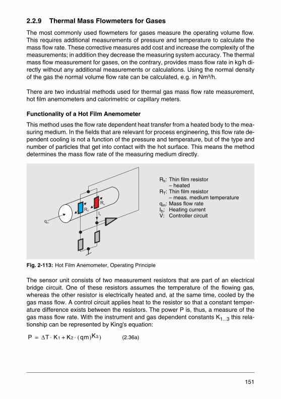
2.2.9 Thermal Mass Flowmeters for Gases
The most commonly used flowmeters for gases measure the operating volume flow.This requires additional measurements of pressure and temperature to calculate themass flow rate. These corrective measures add cost and increase the complexity of themeasurements; in addition they decrease the measuring system accuracy. The thermalmass flow measurement for gases, on the contrary, provides mass flow rate in kg/h di-rectly without any additional measurements or calculations. Using the normal densityof the gas the normal volume flow rate can be calculated, e.g. in Nm³/h.
There are two industrial methods used for thermal gas mass flow rate measurement,hot film anemometers and calorimetric or capillary meters.
Functionality of a Hot Film Anemometer
This method uses the flow rate dependent heat transfer from a heated body to the mea-suring medium. In the fields that are relevant for process engineering, this flow rate de-pendent cooling is not a function of the pressure and temperature, but of the type andnumber of particles that get into contact with the hot surface. This means the methoddetermines the mass flow rate of the measuring medium directly.
Fig. 2-113: Hot Film Anemometer, Operating Principle
The sensor unit consists of two measurement resistors that are part of an electricalbridge circuit. One of these resistors assumes the temperature of the flowing gas,whereas the other resistor is electrically heated and, at the same time, cooled by thegas mass flow. A control circuit applies heat to the resistor so that a constant temper-ature difference exists between the resistors. The power P is, thus, a measure of thegas mass flow rate. With the instrument and gas dependent constants K1...3 this rela-tionship can be represented by King's equation:
(2.36a)
RT
Rh
qm
Ih
Rh: Thin film resistor– heated
RT: Thin film resistor – meas. medium temperature
qm: Mass flow rateIh: Heating currentV: Controller circuit
P ΔT K1 K2 qm( )K3 )⋅+⋅=
151

This provides the measured value directly in the units kg/h or standard m3/h. The den-sity correction of the measured value otherwise required is no longer necessary. Thecompact design of the sensor unit assures a minimum pressure drop of typically1 mbar. For thin film sensors the response time is in the ms range. Vibration insensiti-vity and an extremely wide span at accuracies up to 1 % of rate are the rule for all ther-mal mass flowmeters.
Thermal Mass Flowmeter in Digital Technology
For digital devices the measuring principle described above was further developed toinclude a gas temperature measurement and appreciably extended diagnostic func-tions. The measuring range could be expanded to 1:150 due to the improved signalquality. The separate measurement of the gas temperature can be used to compensatefor the temperature dependence of the gas constants. The diagnostic functions can beused as a preventative maintenance tool to evaluate the operating time, temperaturespikes and system loads.
Technical Designs
Different device concepts were developed for pneumatic, test bench, machine con-struction, hygienic and chemical process applications. Their primary difference is thedesign of the sensor units, dependent on whether quick response, flexibility or chemicalresistance is required.
Devices for the Process Technology
With the Sensyflow FMT400-VTS and FMT500-IG flowmeters rugged, universal devicemodels are available for process applications. All models are connected to the processvia special pipe components which ensure a defined, reproducible installation condi-tion.
– Sensyflow FMT400-VTS is a flowmeter with integral mount design which directly provides a flow rate proportional 0/4…20 mA signal.
– The digital Sensyflow FMT500-IG is available with PROFIBUS DPV1 or analog/HART communication. It can be delivered with up to 4 characteristic curves for dif-ferent gases or pipe diameters.
For hygienic applications the Sensyflow FMT400-VTCS series flowmeters can beused. Special materials and an adapted sensor design make the devices capable ofCIP and SIP.
152
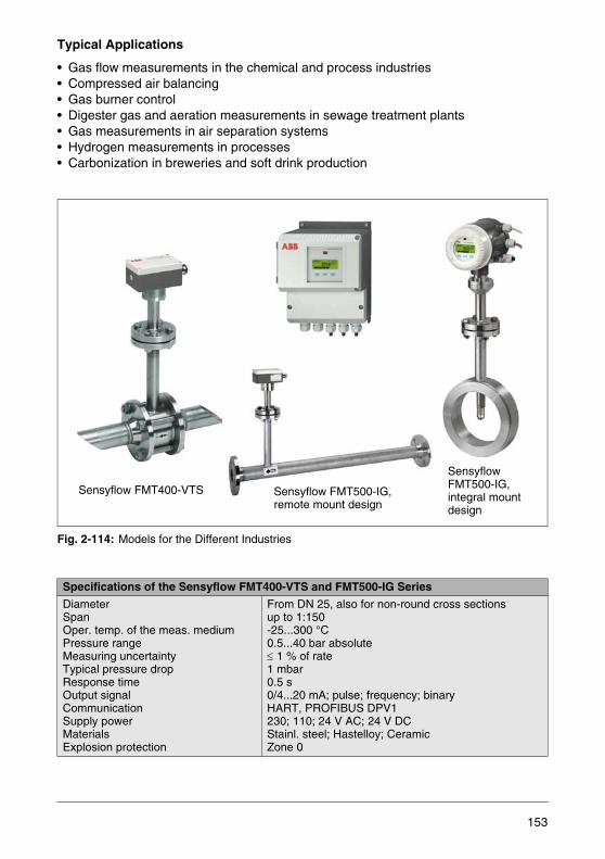
Typical Applications
• Gas flow measurements in the chemical and process industries• Compressed air balancing• Gas burner control• Digester gas and aeration measurements in sewage treatment plants• Gas measurements in air separation systems• Hydrogen measurements in processes• Carbonization in breweries and soft drink production
Fig. 2-114: Models for the Different Industries
Specifications of the Sensyflow FMT400-VTS and FMT500-IG Series
DiameterSpanOper. temp. of the meas. mediumPressure rangeMeasuring uncertaintyTypical pressure dropResponse timeOutput signalCommunicationSupply powerMaterialsExplosion protection
From DN 25, also for non-round cross sectionsup to 1:150-25...300 °C0.5...40 bar absolute≤ 1 % of rate1 mbar0.5 s0/4...20 mA; pulse; frequency; binaryHART, PROFIBUS DPV1230; 110; 24 V AC; 24 V DCStainl. steel; Hastelloy; CeramicZone 0
Sensyflow FMT400-VTS Sensyflow FMT500-IG,remote mount design
Sensyflow FMT500-IG,integral mount design
153
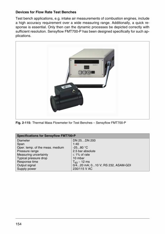
Devices for Flow Rate Test Benches
Test bench applications, e.g. intake air measurements of combustion engines, includea high accuracy requirement over a wide measuring range. Additionally, a quick re-sponse is essential. Only then can the dynamic processes be depicted correctly withsufficient resolution. Sensyflow FMT700-P has been designed specifically for such ap-plications.
Fig. 2-115: Thermal Mass Flowmeter for Test Benches – Sensyflow FMT700-P
Specifications for Sensyflow FMT700-P
DiameterSpanOper. temp. of the meas. mediumPressure rangeMeasuring uncertaintyTypical pressure dropResponse timeOutput signalSupply power
DN 25…DN 2001:40-25...80 °C2.5 bar absolute≤ 1% of rate10 mbarT63 ~ 12 ms0/4...20 mA; 0...10 V; RS 232, ASAM-GDI230/115 V AC
154
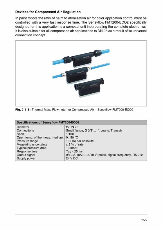
Devices for Compressed Air Regulation
In paint robots the ratio of paint to atomization air for color application control must becontrolled with a very fast response time. The Sensyflow FMT200-ECO2 specificallydesigned for this application is a compact unit incorporating the complete electronics.It is also suitable for all compressed air applications to DN 25 as a result of its universalconnection concept.
Fig. 2-116: Thermal Mass Flowmeter for Compressed Air – Sensyflow FMT200-ECO2
Specifications of Sensyflow FMT200-ECO2
DiameterConnectionsSpanOper. temp. of the meas. mediumPressure rangeMeasuring uncertaintyTypical pressure dropResponse timeOutput signalSupply power
to DN 25Small flange, G 3/8"...1", Legris, Transair1:1000...50 °C10 (16) bar absolute≤ 3 % of rate10 mbarT63 ~ 25 ms0/4...20 mA; 0...5/10 V; pulse, digital, frequency, RS 23224 V DC
155
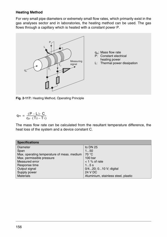
Heating Method
For very small pipe diameters or extremely small flow rates, which primarily exist in thegas analyses sector and in laboratories, the heating method can be used. The gasflows through a capillary which is heated with a constant power P.
Fig. 2-117: Heating Method, Operating Principle
The mass flow rate can be calculated from the resultant temperature difference, theheat loss of the system and a device constant C.
Specifications
DiameterSpanMax. operating temperature of meas. mediumMax. permissible pressureMeasured errorResponse timeOutput signalSupply powerMaterials
to DN 251...5070 °C100 bar< 1 % of rate1...5 s0/4...20; 0...10 V; digital24 V DCAluminium, stainless steel, plastic
T1qm
T2
L
P
Measuringsignal
qm: Mass flow rateP: Constant electrical
heating powerL: Thermal power dissipation
qmP( L ) C⋅–
cp T2 T1–( )⋅---------------------------------=
156

2.3 Flow in Open Channels and Free Surface Pipelines
2.3.1 Flow Measurement in Open Channels
Open channels are found extensively in the water and waste water industries. They arecharacterized by one surface bounded by the atmosphere. The same is valid for freesurface pipelines which are additionally found in the process industry.
Fig. 2-118: Flow Rate Measurement Methods
hh
hh
Indirect method using height measurement
With measuring weirs
With Venturi flumes
Velocity measurement in a free surface pipeline using an electro-magnetic flowmeter
Flowmeter in a fully filled culvert
Flowmeter for partially filled pipes
157

Measurement Methods
Measuring Weirs
For large water flows and small slopes where the water can be dammed and the flowstream is completely ventilated measuring overflows are the appropriate measuringequipment. Ventilation means that air has free access under the overflow so that thestream will separate and fall freely. Measuring weirs consist of thin wall plates withsharp metering edges placed perpendicular to the flow direction. Various shapes areused as a function of the application conditions. For smaller flow rates a V-notch weiris used.
Fig. 2-119: Thomson V-Notch Weir
Based on Equation (1.27) the flow through the V-notch weir is:
The discharge coefficient μ is a function of the ratio of the overflow height h to the weirheight w. The value can be determined using a complicated calculation procedure.Fig. 2-120 shows the μ values in curve form.
Fig. 2-120: Discharge Coefficient μ for a V-Notch Weir per Rehbock and Thomson
(2.37)
w
h
qv8
15------ μ α
2--- g h⋅tan h5 2/⋅ ⋅ ⋅=
μ
h [m
]
0h:w=
0.1 0.2 0.3 0.4 0.5 0.6 0.7 0.8 0.9 1.0
0.05
0.10
0.20
0.40
0.50
0.30
1.00
0.60 0.62 0.64 0.66 0.68 0.70
158
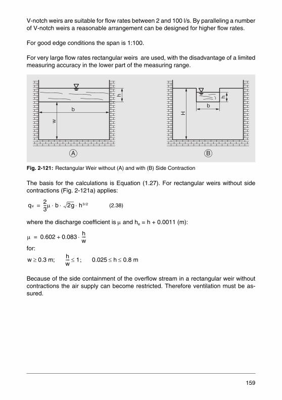
V-notch weirs are suitable for flow rates between 2 and 100 l/s. By paralleling a numberof V-notch weirs a reasonable arrangement can be designed for higher flow rates.
For good edge conditions the span is 1:100.
For very large flow rates rectangular weirs are used, with the disadvantage of a limitedmeasuring accuracy in the lower part of the measuring range.
Fig. 2-121: Rectangular Weir without (A) and with (B) Side Contraction
The basis for the calculations is Equation (1.27). For rectangular weirs without sidecontractions (Fig. 2-121a) applies:
where the discharge coefficient is μ and he = h + 0.0011 (m):
for:
Because of the side containment of the overflow stream in a rectangular weir withoutcontractions the air supply can become restricted. Therefore ventilation must be as-sured.
(2.38)
H
h
b
B
w
b
h
A
qv23---μ b 2g h3 2/⋅ ⋅ ⋅=
μ 0.602 0.083 hw----⋅+=
w 0.3 m;≥ hw---- 1;≤ 0.025 h 0.8 m≤ ≤
159
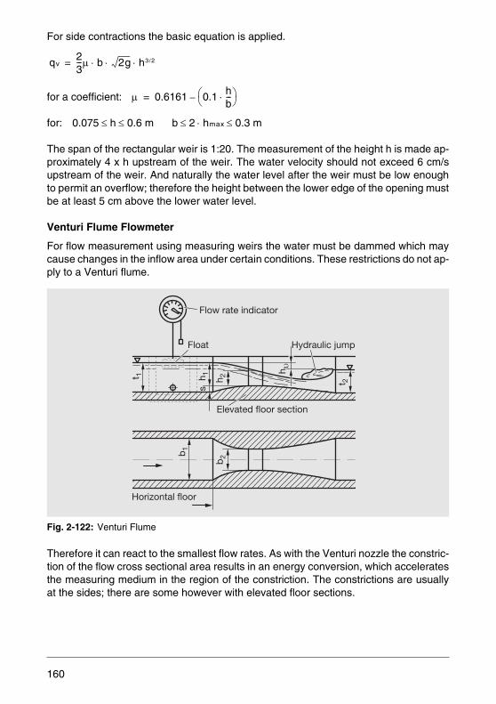
For side contractions the basic equation is applied.
for a coefficient:
for:
The span of the rectangular weir is 1:20. The measurement of the height h is made ap-proximately 4 x h upstream of the weir. The water velocity should not exceed 6 cm/supstream of the weir. And naturally the water level after the weir must be low enoughto permit an overflow; therefore the height between the lower edge of the opening mustbe at least 5 cm above the lower water level.
Venturi Flume Flowmeter
For flow measurement using measuring weirs the water must be dammed which maycause changes in the inflow area under certain conditions. These restrictions do not ap-ply to a Venturi flume.
Fig. 2-122: Venturi Flume
Therefore it can react to the smallest flow rates. As with the Venturi nozzle the constric-tion of the flow cross sectional area results in an energy conversion, which acceleratesthe measuring medium in the region of the constriction. The constrictions are usuallyat the sides; there are some however with elevated floor sections.
qv23---μ b 2g h3 2/⋅ ⋅ ⋅=
μ 0.6161 0.1 hb---⋅⎝ ⎠
⎛ ⎞–=
0.075 h 0.6 m≤ ≤ b 2 hmax 0.3 m≤⋅≤
b1
Horizontal floor
b2
t 1 h 1 h 2
h
t 2s
Hydraulic jumpFloat
Elevated floor section
Flow rate indicator
160
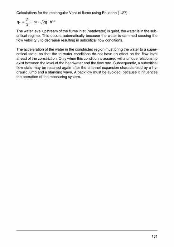
Calculations for the rectangular Venturi flume using Equation (1.27):
The water level upstream of the flume inlet (headwater) is quiet, the water is in the sub-critical regime. This occurs automatically because the water is dammed causing theflow velocity v to decrease resulting in subcritical flow conditions.
The acceleration of the water in the constricted region must bring the water to a super-critical state, so that the tailwater conditions do not have an effect on the flow levelahead of the constriction. Only when this condition is assured will a unique relationshipexist between the level of the headwater and the flow rate. Subsequently, a subcriticalflow state may be reached again after the channel expansion characterized by a hy-draulic jump and a standing wave. A backflow must be avoided, because it influencesthe operation of the measuring system.
qv23---μ b2 2g h3 2/⋅ ⋅ ⋅=
161
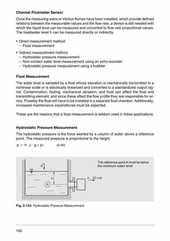
Channel Flowmeter Sensor
Once the measuring weirs or Venturi flumes have been installed, which provide definedrelations between the measurable values and the flow rate, a device is still needed withwhich the liquid level can be measured and converted to flow rate proportional values.The headwater level h can be measured directly or indirectly.
• Direct measurement method– Float measurement
• Indirect measurement method– Hydrostatic pressure measurement– Non-contact water level measurement using an echo-sounder– Hydrostatic pressure measurement using a bubbler
Float Measurement
The water level is sampled by a float whose elevation is mechanically transmitted to anonlinear scale or is electrically linearized and converted to a standardized output sig-nal. Contamination, fouling, mechanical abrasion, and frost can affect the float andtransmitting element, and since these affect the flow profile they are responsible for er-rors. Possibly the float will have to be installed in a separate float chamber. Additionally,increased maintenance expenditures must be expected.
These are the reasons that a float measurement is seldom used in these applications.
Hydrostatic Pressure Measurement
The hydrostatic pressure is the force exerted by a column of water above a referencepoint. The measured pressure is proportional to the height.
Fig. 2-123: Hydrostatic Pressure Measurement
(2.40)p h ρ g p0+⋅ ⋅=
h
P0
4... 20 mA
A
The reference point A must lie below the minimum water level.
162
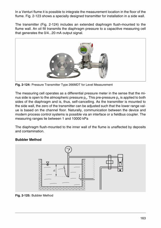
In a Venturi flume it is possible to integrate the measurement location in the floor of theflume. Fig. 2-123 shows a specially designed transmitter for installation in a side wall.
The transmitter (Fig. 2-124) includes an extended diaphragm flush-mounted to theflume wall. An oil fill transmits the diaphragm pressure to a capacitive measuring cellthat generates the 0/4...20 mA output signal.
Fig. 2-124: Pressure Transmitter Type 266MDT for Level Measurement
The measuring cell operates as a differential pressure meter in the sense that the mi-nus side is open to the atmospheric pressure po. This pre-pressure po is applied to bothsides of the diaphragm and is, thus, self-cancelling. As the transmitter is mounted tothe side wall, the zero of the transmitter can be adjusted such that the lower range val-ue is based on the channel floor. Naturally, communication between the device andmodern process control systems is possible via an interface or a fieldbus coupler. Themeasuring ranges lie between 1 and 10000 kPa
The diaphragm flush-mounted to the inner wall of the flume is unaffected by depositsand contamination.
Bubbler Method
Fig. 2-125: Bubbler Method
h
163
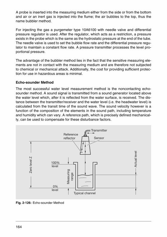
A probe is inserted into the measuring medium either from the side or from the bottomand air or an inert gas is injected into the flume; the air bubbles to the top, thus thename bubbler method.
For injecting the gas a purgemeter type 10A6100 with needle valve and differentialpressure regulator is used. After the regulator, which acts as a restriction, a pressureexists in the probe which is the same as the hydrostatic pressure at the end of the tube.The needle valve is used to set the bubble flow rate and the differential pressure regu-lator to maintain a constant flow rate. A pressure transmitter processes the level pro-portional pressure.
The advantage of the bubbler method lies in the fact that the sensitive measuring ele-ments are not in contact with the measuring medium and are therefore not subjectedto chemical or mechanical attack. Additionally, the cost for providing sufficient protec-tion for use in hazardous areas is minimal.
Echo-sounder Method
The most successful water level measurement method is the noncontacting echo-sounder method. A sound signal is transmitted from a sound generator located abovethe water level which, after it is reflected from the water surface, is received. The dis-tance between the transmitter/receiver and the water level (i.e. the headwater level) iscalculated from the transit time of the sound wave. The sound velocity however is afunction of the composition of the elements in the sound path, including temperatureand humidity which can vary. A reference path, which is precisely defined mechanical-ly, can be used to compensate for these disturbance factors.
Fig. 2-126: Echo-sounder Method
Act
ual l
evel
Typical channel
TransmitterReferencereflector Sensor
Mea
surin
gra
nge
100%
0%
level
level
Zer
o le
vel Z
164

A cone is installed at the sensor to protect against external influences, e.g. snow falland to shield against undesirable wall reflections.
The connected transmitter includes a microprocessor which uses stored curves for dif-ferent flume meters to calculate the flow rate proportional 0/4 ... 20 mA output signal.Naturally such transmitters provide self-monitoring functions, alarm contacts and vol-ume totalizers.
2.3.2 Flow Measurement in Free Surface Pipelines
There are closed pipeline systems which are not continuously filled with liquid but runpartially full because their size had to be selected to accommodate sporadic high flows.The most important example is in the waste water lines, in which the flow at night issmall, somewhat more during the day, but is extremely high after a rain storm. This ap-plication requires a flowmeter which provides accurate measuring values under allthese conditions.
The waste water containing solids prevents the installation of devices projecting intothe pipeline. Therefore, the ideal measuring device is an electromagnetic flowmeter.With one minor disadvantage: the actually measured variable is the flow velocity v.The desired flow rate is available only after multiplying by the filled cross sectional areaA, qv = v · A . Since A, as noted above, is constantly changing there are two possiblesolutions for the measurement. Either arrange the pipeline so that it always runs full orinstall the electromagnetic flowmeter FXP4000 specifically designed for these applica-tions.
Electromagnetic Flowmeter in a Culvert
A culvert (Fig. 2-127) can be used to assure that the pipe always runs full and a correctmeasurement can be made. An argument against the culverts is the danger that solidswill be deposited, especially in waste water applications.
Fig. 2-127: Electromagnetic Flowmeter in a Culvert
165
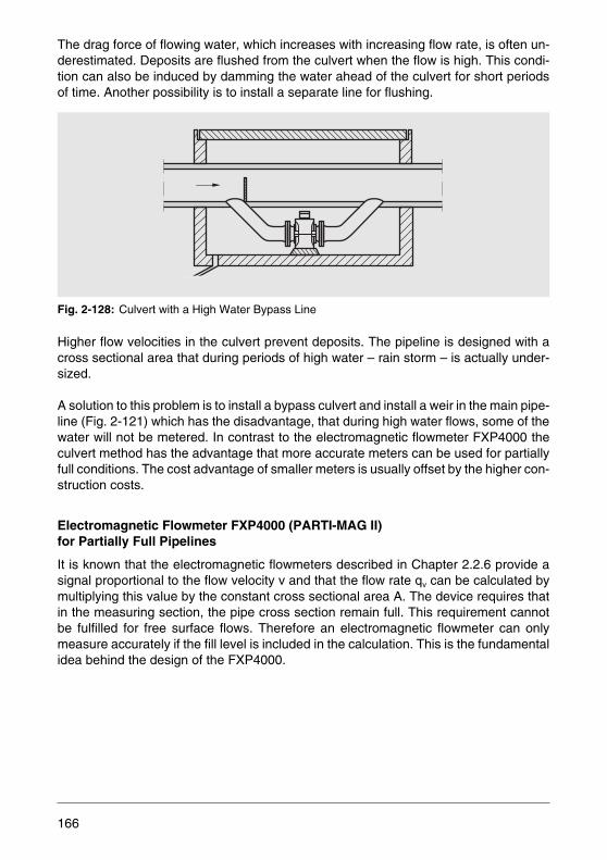
The drag force of flowing water, which increases with increasing flow rate, is often un-derestimated. Deposits are flushed from the culvert when the flow is high. This condi-tion can also be induced by damming the water ahead of the culvert for short periodsof time. Another possibility is to install a separate line for flushing.
Fig. 2-128: Culvert with a High Water Bypass Line
Higher flow velocities in the culvert prevent deposits. The pipeline is designed with across sectional area that during periods of high water – rain storm – is actually under-sized.
A solution to this problem is to install a bypass culvert and install a weir in the main pipe-line (Fig. 2-121) which has the disadvantage, that during high water flows, some of thewater will not be metered. In contrast to the electromagnetic flowmeter FXP4000 theculvert method has the advantage that more accurate meters can be used for partiallyfull conditions. The cost advantage of smaller meters is usually offset by the higher con-struction costs.
Electromagnetic Flowmeter FXP4000 (PARTI-MAG II) for Partially Full Pipelines
It is known that the electromagnetic flowmeters described in Chapter 2.2.6 provide asignal proportional to the flow velocity v and that the flow rate qv can be calculated bymultiplying this value by the constant cross sectional area A. The device requires thatin the measuring section, the pipe cross section remain full. This requirement cannotbe fulfilled for free surface flows. Therefore an electromagnetic flowmeter can onlymeasure accurately if the fill level is included in the calculation. This is the fundamentalidea behind the design of the FXP4000.
166
For the determination of two unknown values the laws of algebra state that two inde-pendent equations, or in this case, two measured values are required.
These measured values are determined as follows:
The volume flow to be measured flows through a meter tube insulated with a liner. Us-ing externally mounted magnet coils at the top and bottom, a magnetic field is generat-ed in the meter tube cross section.
Fig. 2-129: Design of the Flowmeter Sensor
As shown in Fig. 2-129, the transmitter of the FXP4000 flowmeter contains four pairsof electrodes installed at different “levels”. To measure the voltage induced in the flow-ing liquid the optimally placed electrode pair A, B or C, based on the fill level, is used.In this way flow rates from a fill level of 10 % all the way up to a full pipe condition canbe measured. This corresponds to 5 % of the cross sectional flow area.
The electrodes are installed perpendicular to the flow direction and to the magneticfield. The induced voltages are measured at these electrodes. When the pipe is full thisvoltage, as in the usual electromagnetic flowmeter, is a “direct measure” for the aver-age flow velocity.
In contrast, in a partially full pipeline the voltage measured at the electrodes must becorrected using a factor. It is determined using a curve stored in the transmitter.
Full pipe electrode
Upper magnetic coil
Liner
Electrode pair A
Electrode pair B
Lower magnetic coil
Electrode pair C
Electrode pair D
167
Fig. 2-130: Correction Curves for Flow Velocity Proportional Voltages Measured at Electrode Pairs A, B, C
The correction curves depicted in Fig. 2-130 show the relationship between two voltag-es Urec/ Uinj.
With the FXP4000 electromagnetic flowmeter a device has been designed that com-bines the advantages of the system described earlier and eliminates the disadvantageswhen the pipeline is partially full. There are no additional pressure drops, costly con-structions are eliminated, and the smallest flow rates at low levels or large flow rateswhen the pipeline is full can be metered.
Fig. 2-131: FXP4000 Electromagnetic Flowmeter Sensor and Transmitter
1 20
A
B
C
1
Urec / UinjUrec / Uinj(0)
F kor
r
168
The quality of the measurement is a function of the velocity profile in the filled state.The accuracy at a full pipeline condition is 1 % of rate; at partially full conditions an ac-curacy of 3 to 5 % of rate can be achieved down to a minimum fill level of 10 % DN.
Fig. 2-132: Flow Rates as a Function of the Nominal Diameter
10
3
4
56
2
8
8
2
65
4
3
10
2
3
3
4
56
2
8
8
2
65
4
3
2
5
4
3
3
4
56
2
8
10
3
4
56
2
8
8
65
4
3
10
10
l/min l/sm /h3
3
4
56
2
8
8
2
65
4
3
10
3
4
56
8
2DN 150
DN 200
DN 250DN 300
DN 350
DN 400
DN 500DN 600DN 700DN 800DN 900DN 100
0
5
104
3
104
3
2
2
103
10
10
10
2
5
4
3
3
2
6
8
2
4
56
8
DN 120
0DN 1
400
4
6
5
10
205 10 30 40 50 60 80 100 %
Vol
ume
flow
rat
e
Flow velocity m/s
Sizing The nominal diameter of the transmitter is determined using the adjoining nomo-graph based on the maximum flow rate under a full meter tube condition utilizing the current flow velocity
169
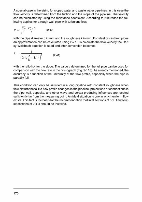
A special case is the sizing for sloped water and waste water pipelines. In this case theflow velocity is determined from the friction and the slope of the pipeline. The velocitycan be calculated by using the resistance coefficient. According to Nikuradse the fol-lowing applies for a rough wall pipe with turbulent flow:
with the pipe diameter d in mm and the roughness k in mm. For steel or cast iron pipesan approximation can be calculated using k = 1. To calculate the flow velocity the Dar-cy-Weisbach equation is used and after conversion becomes:
with the ratio hv/l for the slope. The value v determined for the full pipe can be used forcomparison with the flow rate in the nomograph (Fig. 2-118). As already mentioned, theaccuracy is a function of the uniformity of the flow profile, especially when the pipe ispartially full.
This condition can only be satisfied in a long pipeline with constant roughness whenflow disturbances like flow profile changes in the pipeline, projections or connections inthe pipe wall, deposits, and other wave and vortex producing influences are locatedsufficiently far from the measuring point. An ideal situation is one in which uniform flowexists. This fact is the basis for the recommendation that inlet sections of 5 x D and out-let sections of 2 x D should be installed.
(2.42)
(2.41)
v hv
l-----
2g d⋅λ
--------------⋅=
λ 1
2 lg dk----- 1.14+⎝ ⎠
⎛ ⎞2
------------------------------------------=
170
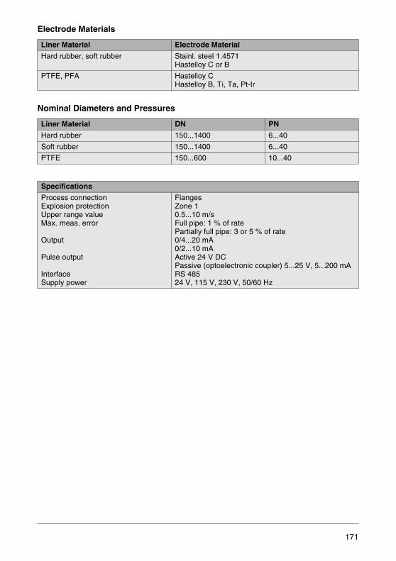
Electrode Materials
Nominal Diameters and Pressures
Liner Material Electrode Material
Hard rubber, soft rubber Stainl. steel 1.4571Hastelloy C or B
PTFE, PFA Hastelloy CHastelloy B, Ti, Ta, Pt-Ir
Liner Material DN PN
Hard rubber 150...1400 6...40
Soft rubber 150...1400 6...40
PTFE 150...600 10...40
Specifications
Process connectionExplosion protectionUpper range valueMax. meas. error
Output
Pulse output
InterfaceSupply power
FlangesZone 10.5...10 m/sFull pipe: 1 % of ratePartially full pipe: 3 or 5 % of rate0/4...20 mA0/2...10 mAActive 24 V DCPassive (optoelectronic coupler) 5...25 V, 5...200 mARS 48524 V, 115 V, 230 V, 50/60 Hz
171


3 Regulations and Requirements Regarding Quality, Environment, Safety and Data Protection
3.1 Integrated Management System
In order for a company to be financially viable it must operate in a correct, market-ori-ented manner. Therefore, the highest goal must be to fulfill the customers' require-ments. Optimal functionality and a long service lifetime at reasonable prices are expect-ed for the products. Product liability requires manufacturing in compliance with thesafety requirements, the applicable standards and regulations, and the generally rec-ognized codes of good practice.
In every company there were and are organizational and procedural systems for theaccomplishment of these tasks. The DIN EN ISO 9000 series of standards about qual-ity management systems worked out and issued in 1983 has become a well-proven ba-sis which allows for international comparability and requires constant monitoring by in-dependent organizations.
Additionally, ABB is committed to active quality and environmental awareness, to safe-ty at work and health protection of its staff, to compliance with the regulations concern-ing careful handling of personal data, and to an open information policy. The individualmanagement systems for quality, environmental protection, safety at work, health pro-tection and data and information protection have been united in a consistent system:the integrated management system.This system meets all requirements on a qualitymanagement system to ISO 9001, an environmental management system to ISO14001, a management system for safety at work and health protection to BS OHSAS18001 and all relevant national laws regarding the protection of data and information.
173
Fig. 3-1: Certificates
174

Fig. 3-2:
175

3.2 Degrees of Protection per EN 60529 (Excerpts from the Standard Sheet)
The standard EN 60529 classifies the protection of electrical equipment by housings,enclosures, or the like. It defines various degrees of protection (IP).
The standard 60529 includes:
• Protection of personnel against electric shock from parts that are energized duringoperation or from approach to such parts as well as protection against physical con-tact with moving parts within the equipment (housings) and protection of the equip-ment against entry of solid objects (physical contact and foreign object protection)
• Protection of equipment against damaging ingress of water (water protection)
Identification
The degrees of protection are designated by a code consisting of the two fixed codeletters IP (Ingress Protection Rating) followed by two code numbers which identify thedegree of protection.
The first code number indicates the degree of protection against physical contact andforeign bodies. The second code number indicates the degree of protection against thedamaging ingress of water.
For designating the full IP code (letters and numbers) the standardized term “Degreeof protection” is to be used.
A housing with the code shown in the example above is protected against the penetra-tion of solid foreign bodies with a diameter greater than 1 mm and against water spray.
If the degree of protection of a part of the equipment, e.g. the terminals, should be dif-ferent from the degree of protection of the main part, the IP code of the deviating partmust be specified separately. In this case, the lower degree of protection is indicatedfirst.
Example: Terminals IP 00 – Housing IP 54
Degree of protection EN 60529- IP 4 4
Name
EN standard number
Code letters
First code number (see Tab. 3-1)
Second code number (see Tab. 3-2)
176
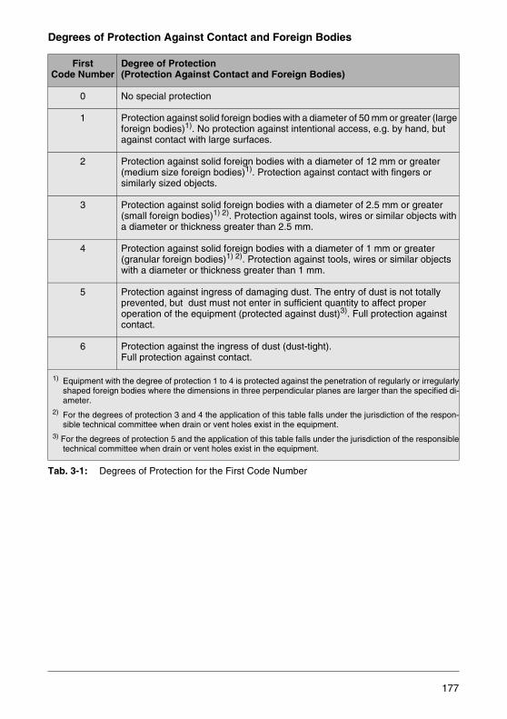
Degrees of Protection Against Contact and Foreign Bodies
Tab. 3-1: Degrees of Protection for the First Code Number
FirstCode Number
Degree of Protection(Protection Against Contact and Foreign Bodies)
0 No special protection
1 Protection against solid foreign bodies with a diameter of 50 mm or greater (large foreign bodies)1). No protection against intentional access, e.g. by hand, but against contact with large surfaces.
2 Protection against solid foreign bodies with a diameter of 12 mm or greater (medium size foreign bodies)1). Protection against contact with fingers orsimilarly sized objects.
3 Protection against solid foreign bodies with a diameter of 2.5 mm or greater (small foreign bodies)1) 2). Protection against tools, wires or similar objects with a diameter or thickness greater than 2.5 mm.
4 Protection against solid foreign bodies with a diameter of 1 mm or greater (granular foreign bodies)1) 2). Protection against tools, wires or similar objects with a diameter or thickness greater than 1 mm.
5 Protection against ingress of damaging dust. The entry of dust is not totally prevented, but dust must not enter in sufficient quantity to affect proper operation of the equipment (protected against dust)3). Full protection against contact.
6 Protection against the ingress of dust (dust-tight). Full protection against contact.
1) Equipment with the degree of protection 1 to 4 is protected against the penetration of regularly or irregularlyshaped foreign bodies where the dimensions in three perpendicular planes are larger than the specified di-ameter.
2) For the degrees of protection 3 and 4 the application of this table falls under the jurisdiction of the respon-sible technical committee when drain or vent holes exist in the equipment.
3) For the degrees of protection 5 and the application of this table falls under the jurisdiction of the responsibletechnical committee when drain or vent holes exist in the equipment.
177
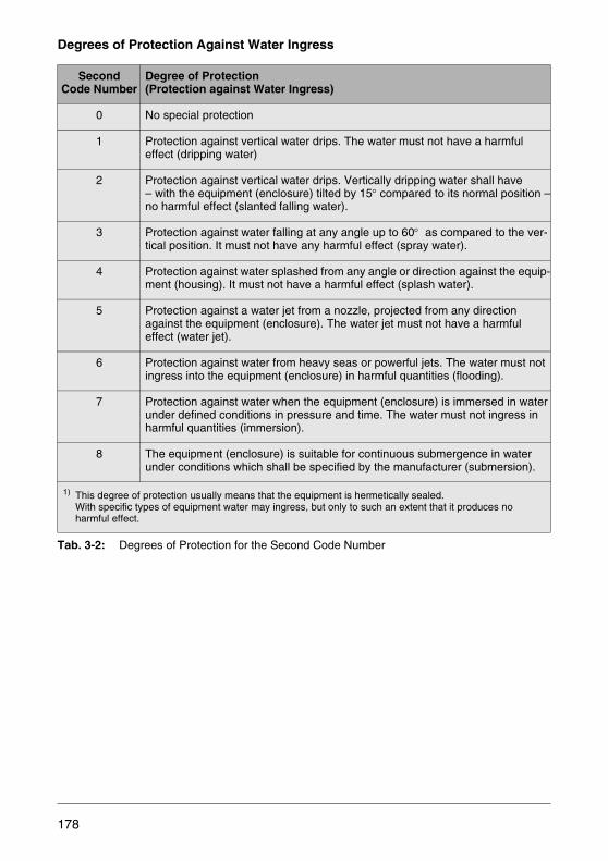
Degrees of Protection Against Water Ingress
Tab. 3-2: Degrees of Protection for the Second Code Number
SecondCode Number
Degree of Protection (Protection against Water Ingress)
0 No special protection
1 Protection against vertical water drips. The water must not have a harmfuleffect (dripping water)
2 Protection against vertical water drips. Vertically dripping water shall have– with the equipment (enclosure) tilted by 15° compared to its normal position –no harmful effect (slanted falling water).
3 Protection against water falling at any angle up to 60° as compared to the ver-tical position. It must not have any harmful effect (spray water).
4 Protection against water splashed from any angle or direction against the equip-ment (housing). It must not have a harmful effect (splash water).
5 Protection against a water jet from a nozzle, projected from any direction against the equipment (enclosure). The water jet must not have a harmful effect (water jet).
6 Protection against water from heavy seas or powerful jets. The water must notingress into the equipment (enclosure) in harmful quantities (flooding).
7 Protection against water when the equipment (enclosure) is immersed in waterunder defined conditions in pressure and time. The water must not ingress in harmful quantities (immersion).
8 The equipment (enclosure) is suitable for continuous submergence in waterunder conditions which shall be specified by the manufacturer (submersion).
1) This degree of protection usually means that the equipment is hermetically sealed. With specific types of equipment water may ingress, but only to such an extent that it produces no harmful effect.
178

3.3 Requirements Regarding Interference Immunity (EMC)
The measuring electronics of flowmeters are constantly becoming more efficient andmore compact. Digital data processing with its microprocessors has opened up new av-enues for new communications, diagnostic functions, and short response times. Theintegral mount design also requires new ways in terms of the power supply. Advancedmeasuring electronics are usually provided with switch-mode power supplies. In orderto ensure reliable functionality and a high immunity to interference, the measuring elec-tronics are subjected to various tests. Electromagnetic compatibility (EMC) plays an es-sential role.
With the advent of the common European market, the European Union has adoptedvarious directives. It is stipulated that all devices released to the European market mustcomply with the valid directives. This is visible to the customer through the CE markthat has to be attached to the devices, and the CE declaration of conformity deliveredwith the devices.
Over the years, the measuring electronics and, thus, the requirements on the test pro-cedures have considerably changed. The EMC Directive has been revised to meetthese new requirements. Since July 20, 2007, the new EMC Directive 2004/108/EChas been in force and applied by the manufacturers.
At national level, the new EMC Directive 2004/108/EC has been implemented, amongothers, through the generic standards EN 61000-6-2:2005 (Immunity standard for in-dustrial environments) and EN 61000-6-4:2007 (Emission standard for industrial envi-ronments). EN 61326 is the product standard for Electrical equipment for measure-ment, control and laboratory use. All ABB flowmeters comply with these standards anddirectives.
Besides the requirements stipulated in EMC Directive 2004/108/EC, there are addition-al requirements, for example for the chemical industry, which are defined in the NA-MUR Recommendations. Here, more stringent test requirements are stipulated than inthe EMC Directive, for example a higher immunity test level.
Moreover, there exist special requirements from the Organisation Internationale deMétrologie Légale (OIML) (English name: International Organization of Legal Metrolo-gy) regarding the measuring accuracy under the influence of electromagnetic interfer-ence.
179
Types of Interference
In the context of electromagnetic compatibility (EMC) a distinction is made between twodifferent types of interference:
• The conducted interference is transmitted directly from the interference source viathe supply or signal line to the load. For example, a clicking noise that you hear onyour radio may be caused by your electrical water boiler being switched off. The au-tomatic switch-off of the water boiler's supply voltage generates a voltage pulse, thespectrum of which lies within the audible frequency range. When voltage pulses ofthis kind are transmitted via the radio power cord, the clicking interference occurs.
• The radiated interference is transmitted to the load via electromagnetic fields and canbe received, for example, by a printed circuit board track operating as an antenna.Also, capacitive or inductive coupling of electrical or magnetic fields is possible. Anexample of radiated interference is a cell phone communication coupled into a radio.The reason for this may be an insufficiently shielded loudspeaker.
Interference Causes
An interference signal may be caused by a voltage variations in time or by currents, e.g.resulting from a switching operation. These produce periodic voltage or current chang-es. The currents and voltages of the interference source that are variable in time causemagnetic or electrical fields which may generate an interference signal at the load.In-terference sources may have the following technical or natural causes:
• Variations in / interruptions of the supply voltage• Electromagnetic fields, generated by transmitters operating in the frequency range
from few kHz (long wave transmission) up to several GHz (cell phones, microwaveovens).
• Lightning electromagnetic pulses (LEMP)• Surge voltage pulses caused by switching operations in low-voltage networks• High-frequency, low-power burst pulses caused by switching operations of switch-
mode power supplies• Electrostatic discharge (ESD)• High-frequency signals produced by load changes of microprocessors or frequency
converters• A nuclear electromagnetic pulse (NEMP) produced by a nuclear weapon explosion
Interference signals are often generated by electrical switches, relays, contactors, flu-orescent lamps, solenoid valves, electric motors, radio transceivers or atmospheric dis-turbances like lightning.
180
Evaluation of the Interference Response
The interference response of a device is a means of evaluating how a device reacts inthe event of a disturbance or interference. There are three evaluation criteria:
• No reduction in functionality.Mainly analog devices may be affected within their error limits. Purely digital devicesmust not be affected at all.
• Reduction in functionality.A certain reduction of the functionality while the device is subjected to the interfer-ence is permissible under the proviso that the device is capable of automatically re-suming normal operation once the interference is over. No permanent damage maybe caused.
• Loss of functionality.Evaluated is primarily the functional failure at the onset of an interference until an au-tomatic or manual restart occurs. When the tolerances are exceeded or underscored,the devices must be capable of restarting automatically or must remain, ready for re-start, in their defined fail-safe position.
Limitation of Interferences
Interferences can be limited by EMI/RFI shielding of the interference source or by pro-viding a sufficient interference immunity of the load.
In order to achieve an EMC compliant circuit layout, the following measures are taken:
• Avoid unnecessary switching operations• Perform unavoidable switching operations as slowly as technically possible• Limit unavoidable interference as far as possible by using the appropriate design el-
ements on site (e.g. RC elements for interference shielding, shielded housings or cables)
• Choose a PCB layout that complies with the EMC requirements (e.g. adapt the length of the PCB tracks to the frequency, use grounding planes for shielding)
• Ensure sufficient interference immunity (e.g. through filters, blocking capacitors orfailure-tolerant software)
Regarding the overall EMC protection independent of the individual devices, the follow-ing is aspired:
• Determine interference sources and loads through system analyses.• Provide for sufficient shielding.• Keep the specified distances.• Improve the interference immunity of the load.
Electromagnetic compatibility of plants and systems can be reliably realized by intro-ducing an interference protection concept with defined conditions for the devices to beused.
181
3.4 Explosion Protection
Among the variety of products and intermediate products of the chemical and industrialprocess industries there are many which can form explosive mixtures with other prod-ucts or with the oxygen in the air. Measurement and control equipment that comes intocontact with such mixtures must not cause an explosion, but must nevertheless oper-ate effectively.
In order for an explosion to occur, a number of events must occur simultaneously:
• A sufficient degree of dispersion (degree of scattering) for mist or dust require particlesizes between 0.1 and 0.001 mm. For gases this degree is provided by nature.
• Only when the concentration of a flammable substance in air exceeds a minimum val-ue does the danger of an explosion exist. On the other hand there is a maximum val-ue (a too rich mixture) above which an explosion can no longer take place.
• Naturally a sufficient amount of the mixture must be available. As little as 10 liters ofan explosive mixture are considered to be dangerous.
• An ignition source must provide sufficient energy in order to initiate the explosion.
Considering these criteria some measures to prevent an explosion inevitably come tomind:
Explosive mixtures are to be avoided, their quantity is to be limited, ignition must beprevented and, in a worst case scenario, the impact of an explosion must be mitigated.
These measures are considered during the design of the instruments. For example, thespace in which an explosive mixture can accumulate is kept very small or the energycontent of a possible spark source is minimized or the explosion is restricted to a smallspace.
182

3.4.1 International Orientation of Explosion Protection
All over the world, the explosion protection is governed by different, country-specificnational standards. For ABB products this means: the same technical design, but dif-ferent, country-specific approvals. Only in this way a worldwide commercialization canbe achieved with little product variance, and customers throughout the world can usethe same product. On the customer side, this strategy yields cost reductions, e.g. fortraining, project planning and maintenance of the corresponding products.
Tab. 3-3: Overview of Important Country-specific Standards, Approvals and Approval Bodies
Basically, the requirements for all approvals are similar to each other and pursue thesame goal: prevent, according to the state of the art, that an explosion can occur in aplant that has been instrumented in compliance with the national explosion protectionrequirements.
European Union
USA Canada Russia Ukraine Australia
Directive / Standard / Approval Body
ATEX– PTB– EXAM
BBG– KEMA– TÜV Nord– ZELM– IBExU ...
FM Ex-ApprovalUL Ex-Approval
CSA-Certificate
GOST Russia
GOST Ukraine
IECEx
Validity No restrictions No restric-tions
No restric-tions
3 years 3 years No restric-tions
Production SupervisionAuditing
yes yes yes no no yes
183
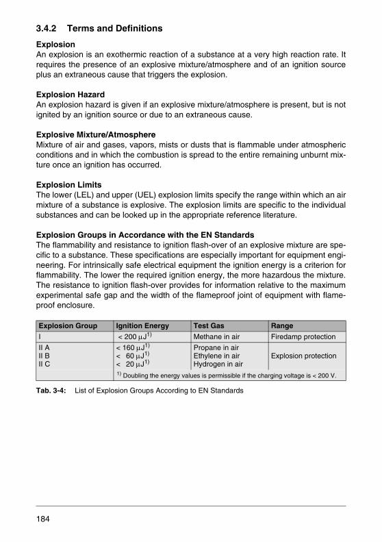
3.4.2 Terms and Definitions
ExplosionAn explosion is an exothermic reaction of a substance at a very high reaction rate. Itrequires the presence of an explosive mixture/atmosphere and of an ignition sourceplus an extraneous cause that triggers the explosion.
Explosion HazardAn explosion hazard is given if an explosive mixture/atmosphere is present, but is notignited by an ignition source or due to an extraneous cause.
Explosive Mixture/AtmosphereMixture of air and gases, vapors, mists or dusts that is flammable under atmosphericconditions and in which the combustion is spread to the entire remaining unburnt mix-ture once an ignition has occurred.
Explosion LimitsThe lower (LEL) and upper (UEL) explosion limits specify the range within which an airmixture of a substance is explosive. The explosion limits are specific to the individualsubstances and can be looked up in the appropriate reference literature.
Explosion Groups in Accordance with the EN StandardsThe flammability and resistance to ignition flash-over of an explosive mixture are spe-cific to a substance. These specifications are especially important for equipment engi-neering. For intrinsically safe electrical equipment the ignition energy is a criterion forflammability. The lower the required ignition energy, the more hazardous the mixture.The resistance to ignition flash-over provides for information relative to the maximumexperimental safe gap and the width of the flameproof joint of equipment with flame-proof enclosure.
Tab. 3-4: List of Explosion Groups According to EN Standards
Explosion Group Ignition Energy Test Gas Range
I < 200 μJ1) Methane in air Firedamp protection
II AII BII C
< 160 μJ1)
< 60 μJ1)
< 20 μJ1)
Propane in airEthylene in airHydrogen in air
Explosion protection
1) Doubling the energy values is permissible if the charging voltage is < 200 V.
184
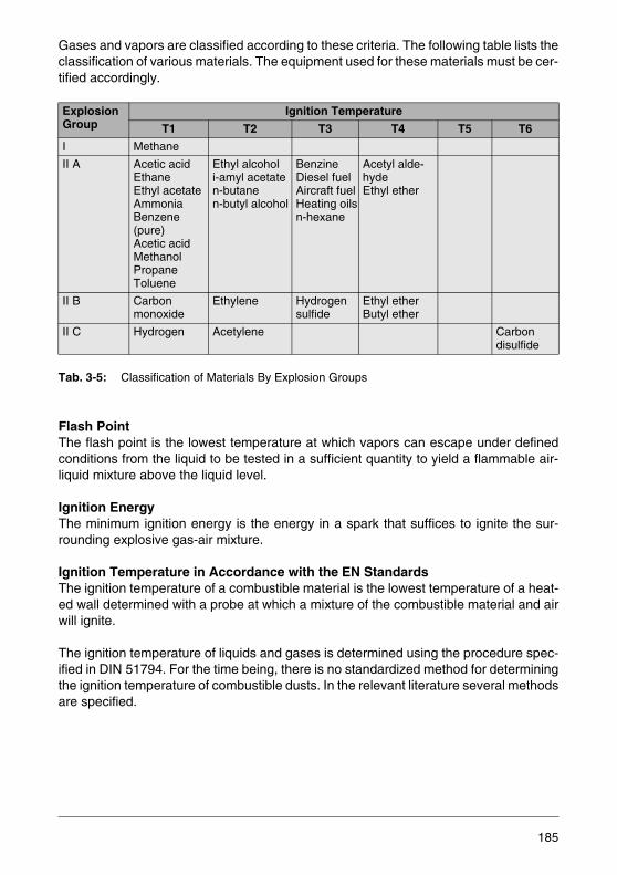
Gases and vapors are classified according to these criteria. The following table lists theclassification of various materials. The equipment used for these materials must be cer-tified accordingly.
Tab. 3-5: Classification of Materials By Explosion Groups
Flash PointThe flash point is the lowest temperature at which vapors can escape under definedconditions from the liquid to be tested in a sufficient quantity to yield a flammable air-liquid mixture above the liquid level.
Ignition Energy The minimum ignition energy is the energy in a spark that suffices to ignite the sur-rounding explosive gas-air mixture.
Ignition Temperature in Accordance with the EN StandardsThe ignition temperature of a combustible material is the lowest temperature of a heat-ed wall determined with a probe at which a mixture of the combustible material and airwill ignite.
The ignition temperature of liquids and gases is determined using the procedure spec-ified in DIN 51794. For the time being, there is no standardized method for determiningthe ignition temperature of combustible dusts. In the relevant literature several methodsare specified.
ExplosionGroup
Ignition Temperature
T1 T2 T3 T4 T5 T6
I Methane
II A Acetic acidEthaneEthyl acetateAmmoniaBenzene (pure)Acetic acidMethanolPropaneToluene
Ethyl alcoholi-amyl acetaten-butane n-butyl alcohol
BenzineDiesel fuelAircraft fuelHeating oilsn-hexane
Acetyl alde-hydeEthyl ether
II B Carbon monoxide
Ethylene Hydrogen sulfide
Ethyl etherButyl ether
II C Hydrogen Acetylene Carbon disulfide
185
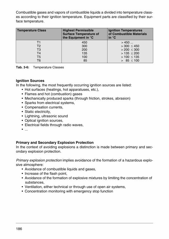
Combustible gases and vapors of combustible liquids a divided into temperature class-es according to their ignition temperature. Equipment parts are classified by their sur-face temperature.
Tab. 3-6: Temperature Classes
Ignition SourcesIn the following, the most frequently occurring ignition sources are listed:
• Hot surfaces (heatings, hot apparatuses, etc.), • Flames and hot (combustion) gases• Mechanically produced sparks (through friction, strokes, abrasion)• Sparks from electrical systems,• Compensation currents,• Static electricity,• Lightning, ultrasonic sound• Optical ignition sources,• Electrical fields through radio waves,• ...
Primary and Secondary Explosion ProtectionIn the context of avoiding explosions a distinction is made between primary and sec-ondary explosion protection.
Primary explosion protection implies avoidance of the formation of a hazardous explo-sive atmosphere:
• Avoidance of combustible liquids and gases,• Increase of the flash point,• Avoidance of the formation of explosive mixtures by limiting the concentration of
substances,• Ventilation, either technical or through use of open air systems,• Concentration monitoring with emergency stop function
Temperature Class Highest PermissibleSurface Temperature of the Equipment in °C
Ignition Temperaturesof Combustible Materialsin °C
T1T2T3T4T5T6
45030020013510085
> 450 ...> 300 ≤ 450> 200 ≤ 300> 135 ≤ 200> 100 ≤ 135> 85 ≤ 100
186

Secondary explosion protection includes all measures that can be taken to prevent theignition of a hazardous atmosphere:
• No effective ignition source- Intrinsically safe equipment- Flameproof enclosure of the ignition source to prevent external ignition Powder filling Encapsulation Flameproof enclosure Pressurized enclosure ...
Zones in Accordance with the EN Standard
The hazardous area is divided into three zones. The probability of the existence of apotentially hazardous atmosphere is a criterion for the division as described below:
For Gases, Vapors and Mists (EN 60079-10)Zone 0: Area, in which a potentially explosive atmosphere in the form of a mixture of
air and combustible gases, vapors or mists is present continuously, for longperiods or frequently.Category: 1 G
Zone 1: Area in which, during normal operation, a potentially explosive atmospherein the form of a mixture of air and combustible gases, vapors or mists canoccur occasionally.Category: 2 G
Zone 2: Area in which, during normal operation, a potentially explosive atmospherein the form of a mixture of air and combustible gases, vapors or mists occursnot at all or only for a short time period.Category: 3 G
For Dusts (EN 61241-10)Zone 20: Area in which a potentially explosive atmosphere in the form of a cloud of com-
bustible dust in air is present continuously, for long periods or frequently. Category: 1 D
Zone 21: Area in which, during normal operation a potentially explosive atmospherein the form of a cloud of combustible dust in air can occur.Category: 2 D
187
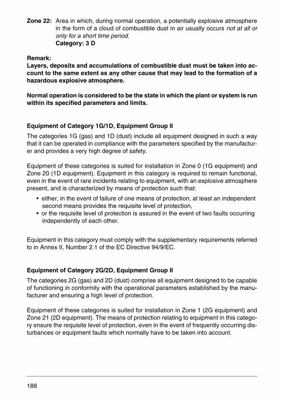
Zone 22: Area in which, during normal operation, a potentially explosive atmospherein the form of a cloud of combustible dust in air usually occurs not at all oronly for a short time period.Category: 3 D
Remark:Layers, deposits and accumulations of combustible dust must be taken into ac-count to the same extent as any other cause that may lead to the formation of ahazardous explosive atmosphere.
Normal operation is considered to be the state in which the plant or system is runwithin its specified parameters and limits.
Equipment of Category 1G/1D, Equipment Group II
The categories 1G (gas) and 1D (dust) include all equipment designed in such a waythat it can be operated in compliance with the parameters specified by the manufactur-er and provides a very high degree of safety.
Equipment of these categories is suited for installation in Zone 0 (1G equipment) andZone 20 (1D equipment). Equipment in this category is required to remain functional,even in the event of rare incidents relating to equipment, with an explosive atmospherepresent, and is characterized by means of protection such that:
• either, in the event of failure of one means of protection, at least an independent second means provides the requisite level of protection,
• or the requisite level of protection is assured in the event of two faults occurring independently of each other.
Equipment in this category must comply with the supplementary requirements referredto in Annex II, Number 2.1 of the EC Directive 94/9/EC.
Equipment of Category 2G/2D, Equipment Group II
The categories 2G (gas) and 2D (dust) comprise all equipment designed to be capableof functioning in conformity with the operational parameters established by the manu-facturer and ensuring a high level of protection.
Equipment of these categories is suited for installation in Zone 1 (2G equipment) andZone 21 (2D equipment). The means of protection relating to equipment in this catego-ry ensure the requisite level of protection, even in the event of frequently occurring dis-turbances or equipment faults which normally have to be taken into account.
188
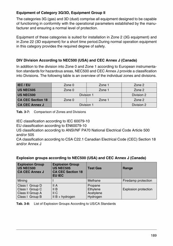
Equipment of Category 3G/3D, Equipment Group II
The categories 3G (gas) and 3D (dust) comprise all equipment designed to be capableof functioning in conformity with the operational parameters established by the manu-facturer and ensuring a normal level of protection.
Equipment of these categories is suited for installation in Zone 2 (3G equipment) andin Zone 22 (3D equipment) for a short time period.During normal operation equipmentin this category provides the required degree of safety.
DIV Division According to NEC500 (USA) and CEC Annex J (Canada)
In addition to the division into Zone 0 and Zone 1 according to European instrumenta-tion standards for hazardous areas, NEC500 and CEC Annex J provide a classificationinto Divisions. The following table is an overview of the individual zones and divisions.
Tab. 3-7: Comparison of Zones and Divisions
IEC classification according to IEC 60079-10EU classification according to EN60079-10US classification according to ANSI/NF PA70 National Electrical Code Article 500 and/or 505CA classification according to CSA C22.1 Canadian Electrical Code (CEC) Section 18 and/or Annex J
Explosion groups according to NEC500 (USA) and CEC Annex J (Canada)
Tab. 3-8: List of Explosion Groups According to US/CA Standards
IEC / EU Zone 0 Zone 1 Zone 2
US NEC505 Zone 0 Zone 1 Zone 2
US NEC500 Division 1 Division 2
CA CEC Section 18 Zone 0 Zone 1 Zone 2
CA CEC Annex J Division 1 Division 2
Explosion GroupUS NEC500CA CEC Annex J
Explosion GroupUS NEC505CA CEC Section 18EU IEC
Test Gas Range
Mining I Methane Firedamp protection
Class I Group DClass I Group CClass II Group AClass I Group B
II AII BII CII B + hydrogen
PropaneEthyleneAcetyleneHydrogen
Explosion protection
189

Temperature Classes According to NEC500 (USA) and CEC Annex J (Canada)
Tab. 3-9: Division of Temperature Classes According to US/CA Standards
Max.Surface Temperature
US NEC505CA CEC Section 18EU IEC
US NEC 500CA CEC Annex J
450 °C300 °C280 °C260 °C230 °C215 °C200 °C180 °C165 °C160 °C135 °C120 °C100 °C 85 °C
T1T2
T3
T4
T5T6
T1T2T2AT2BT2CT2DT3T3AT3BT3CT4T4AT5T6
190
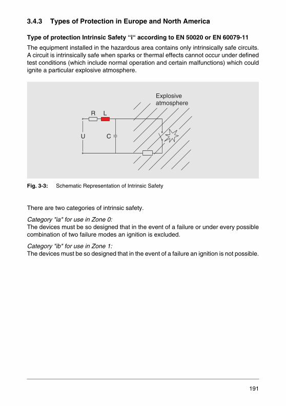
3.4.3 Types of Protection in Europe and North America
Type of protection Intrinsic Safety “i“ according to EN 50020 or EN 60079-11
The equipment installed in the hazardous area contains only intrinsically safe circuits.A circuit is intrinsically safe when sparks or thermal effects cannot occur under definedtest conditions (which include normal operation and certain malfunctions) which couldignite a particular explosive atmosphere.
Fig. 3-3: Schematic Representation of Intrinsic Safety
There are two categories of intrinsic safety.
Category "ia" for use in Zone 0:The devices must be so designed that in the event of a failure or under every possiblecombination of two failure modes an ignition is excluded.
Category "ib" for use in Zone 1:The devices must be so designed that in the event of a failure an ignition is not possible.
R L
U C
Explosiveatmosphere
191
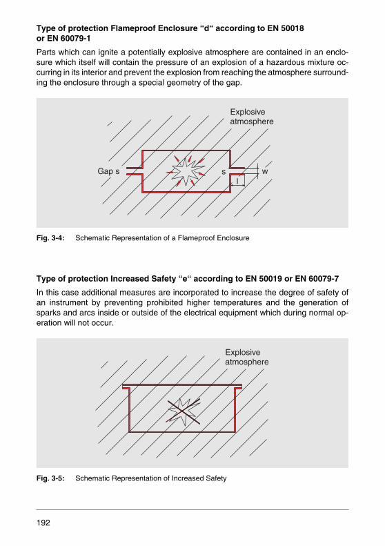
Type of protection Flameproof Enclosure “d“ according to EN 50018 or EN 60079-1
Parts which can ignite a potentially explosive atmosphere are contained in an enclo-sure which itself will contain the pressure of an explosion of a hazardous mixture oc-curring in its interior and prevent the explosion from reaching the atmosphere surround-ing the enclosure through a special geometry of the gap.
Fig. 3-4: Schematic Representation of a Flameproof Enclosure
Type of protection Increased Safety “e“ according to EN 50019 or EN 60079-7
In this case additional measures are incorporated to increase the degree of safety ofan instrument by preventing prohibited higher temperatures and the generation ofsparks and arcs inside or outside of the electrical equipment which during normal op-eration will not occur.
Fig. 3-5: Schematic Representation of Increased Safety
l
Explosiveatmosphere
Gap s s w
Explosiveatmosphere
192

Type of protection Pressurized Enclosure “p“ according to EN 50016 or EN 60079-13
The entry of an explosive atmosphere into the housing of electrical equipment is pre-vented by filling the interior of the housing with an ignition protecting gas (air, inert orother appropriate gas) under a pressure greater than that of the surrounding atmo-sphere. The overpressure is maintained with or without constant flushing with protec-tive gas.
Fig. 3-6: Schematic Representation of Pressurized Enclosure
Type of protection Oil Immersion “o“ according to EN 50015 or EN 60079-6
Electrical equipment or parts thereof are made safe by by surrounding them with oil sothat an explosive atmosphere on the surface or outside of the housing will not beignited.
Fig. 3-7: Schematic Representation of Oil-Immersion
P
h↑↓
193
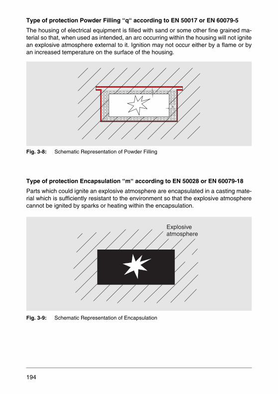
Type of protection Powder Filling “q“ according to EN 50017 or EN 60079-5
The housing of electrical equipment is filled with sand or some other fine grained ma-terial so that, when used as intended, an arc occurring within the housing will not ignitean explosive atmosphere external to it. Ignition may not occur either by a flame or byan increased temperature on the surface of the housing.
Fig. 3-8: Schematic Representation of Powder Filling
Type of protection Encapsulation “m“ according to EN 50028 or EN 60079-18
Parts which could ignite an explosive atmosphere are encapsulated in a casting mate-rial which is sufficiently resistant to the environment so that the explosive atmospherecannot be ignited by sparks or heating within the encapsulation.
Fig. 3-9: Schematic Representation of Encapsulation
↓
↑d
h↑
Explosiveatmosphere
194
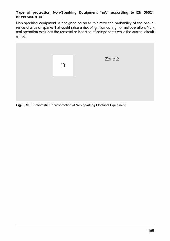
Type of protection Non-Sparking Equipment “nA“ according to EN 50021or EN 60079-15
Non-sparking equipment is designed so as to minimize the probability of the occur-rence of arcs or sparks that could raise a risk of ignition during normal operation. Nor-mal operation excludes the removal or insertion of components while the current circuitis live.
Fig. 3-10: Schematic Representation of Non-sparking Electrical Equipment
Zone 2
n
195

3.4.4 Approvals According to the FM Approval Standards
Flowmeters from ABB fulfill the following FM standards, depending on the certificationand field of application:
• Intrinsically Safe Apparatus and Associated Apparatus for use in Class I, II and III, Division 1, and Class I, Zone 0 and 1.Hazardous (Classified) Locations. Approval Standard Class Number 3610.
• Nonincendive Electrical Equipment foruse in Class I and II, Division 2, and Class III, Divisions 1 and 2.Hazardous (Classified) Locations. Approval Standard Class Number 3611.
• Explosionproof Electrical Equipment General Requirements.Approval Standard Class Number 3615.
The corresponding operating instruction and the Control Drawing must be observedwhen installing the device. Additionally, the National Electrical Code (NEC) must be ob-served for the installation.
3.4.5 Approvals in Accordance with the CSA Standards
Flowmeters from ABB fulfill one or more of the following CSA standards, depending onthe certification and field of application:
• CAN/CSA-E60079-11:02 Electrical apparatus for explosive gas atmospheres -Part 11: Intrinsic safety „i“C22.2 No.213-M1987 (Reaffirmed 1999) Non-incendive Electrical Equipmentfor use in Class I, Division 2. Hazardous Locations.
• C22.2 No. 30-M1986 (Reaffirmed 1999) Explosion-proof Enclosuresfor use in Class I. Hazardous Locations.
The corresponding operating instruction and the Control Drawing must be observedwhen installing the device. Additionally, the Canadian Electrical Code (CEC) Part I(Safety Standard for Electrical Installation) must be observed for installation.
196

3.4.6 Free Movement of Goods Related to Explosion-Proof ElectricalDevices
The prerequisite for the free movement of goods within the European Community isgoverned by EC Directives. Since July 1st, 2003, the Directive 94/9/EC (ATEX 95, for-merly 100a) must be applied.
Additionally, ATEX 95 a conformity evaluation of the Quality Assurance of the manu-facturer, which includes special requirements for explosion proof equipment during de-velopment, design and manufacturing.
Device that have been tested in accordance with ATEX 95 and for which a Type Exam-ination Certificate has been granted by the certifying body are additionally identified bya CE mark. The identification number of the test body who has evaluated the qualityassurance is also added.
The specifications and the safety-relevant sections of the operating instruction must beprovided in the national language of the country where the product is used.
3.4.7 Identification of Equipment
Equipment intended for use in hazardous areas must be uniquely identified by the man-ufacturer. To comply with EN 50014 or EN 60079-0 / EN 50020 or EN 60079-11 theequipment must be labeled with the following information:
• Manufacturer name and address• CE mark• Designation of the series and type• Serial number, if applicable• Year of manufacture• Special identification for the prevention of explosions in conjunction with the identifi-
cation of the category
• For the equipment group II the letter “G” (for areas in which potentially explosive gas,vapor, mist and air mixtures are present) and/or the letter “D”(for areas where dust may form potentially explosive atmospheres).
197
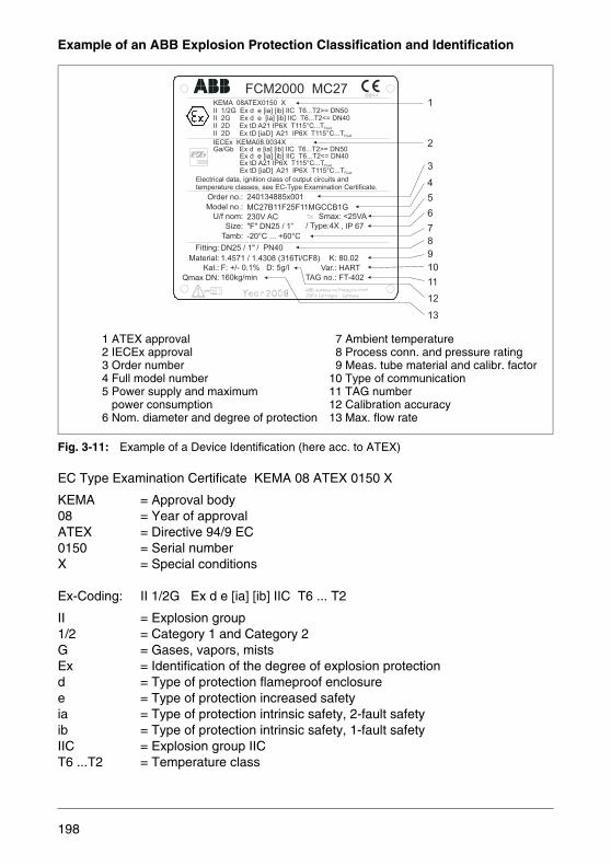
Example of an ABB Explosion Protection Classification and Identification
Fig. 3-11: Example of a Device Identification (here acc. to ATEX)
EC Type Examination Certificate KEMA 08 ATEX 0150 X
KEMA = Approval body08 = Year of approvalATEX = Directive 94/9 EC0150 = Serial numberX = Special conditions
Ex-Coding: II 1/2G Ex d e [ia] [ib] IIC T6 ... T2
II = Explosion group1/2 = Category 1 and Category 2G = Gases, vapors, mistsEx = Identification of the degree of explosion protectiond = Type of protection flameproof enclosuree = Type of protection increased safetyia = Type of protection intrinsic safety, 2-fault safetyib = Type of protection intrinsic safety, 1-fault safetyIIC = Explosion group IICT6 ...T2 = Temperature class
FCM2000 MC27
2
1
3
4
5
6
7
8
9
10
11
12
13
Order no.:
Model no.:
U/f nom:
Tamb:
Size:
Electrical data, ignition class of output circuits and
KEMA 08ATEX0150 X
IECEx KEMA08.0034X
II 1/2G Ex d e [ia] [ib] IIC T6...T2>= DN50
Ga/Gb Ex d e [ia] [ib] IIC T6...T2>= DN50
II 2G Ex d e [ia] [ib] IIC T6...T2<= DN40II 2D Ex tD A21 IP6X T115°C...TFluid
Ex tD A21 IP6X T115°C...TFluid
II 2D Ex tD [iaD] A21 IP6X T115°C...TFluid
Ex tD [iaD] A21 IP6X T115°C...TFluid
Ex d e [ia] [ib] IIC T6...T2<= DN40
temperature classes, see EC-Type Examination Certificate.
Fitting:
Material:
Kal.:
Qmax DN: TAG no.: FT-402
240134885x001
Smax: <25VA
"F" DN25 / 1” / Type:4X
DN25 / 1"
160kg/min
F: +/- 0.1% D: 5g/l Var.: HART
1.4571 / 1.4308 (316Ti/CF8)
, IP 67
-20°C ... +60°C
/ PN40
K: 80.02
230V AC
MC27B11F25F11MGCCB1G
1 ATEX approval2 IECEx approval3 Order number4 Full model number5 Power supply and maximum
power consumption6 Nom. diameter and degree of protection
7 Ambient temperature8 Process conn. and pressure rating9 Meas. tube material and calibr. factor
10 Type of communication11 TAG number12 Calibration accuracy13 Max. flow rate
198
3.5 GOST Approvals for Flow Measurement
Note: ABB cannot assume any liability regarding possible legal amendments of the ap-proval procedures or formalities nor for possible legal regulations that are additionallyvalid in Russia, Belarus, Ukraine and Kazakhstan.
3.5.1 Russia
GOST-R Certificate of Conformity
The GOST-R certificate is obligatory.
OriginThe designation “Gost-R Certificate of Conformity” has established itself in the courseof time. It is a translation from the Russian word for “compliance certificate” meaningthat the certified product meets the requirments of the corresponding GOST standards.
Introduction of the GOST-R Certification System
In 1989, the Russian authorities introduced preliminary regulations for the assuranceof products manufactured and commercialized in Russia in order to provide for con-sumer protection. In the early 90ies these regulations have come into force. This wasthe legal and technical basis for the creation of the national certification system. From1992 on these regulations have been put into practice.
All products that are produced or imported into the Russian Federation are subjectedto obligatory certification. The GOST-R Certificate of Conformity corresponds to the CEDeclaration of Conformity.
The GOST-R certificate differs from the CE declaration in that the CE Declaration ofConformity can be issued by the manufacturer himself whereas the GOST-R Certificateof Conformity can only be awarded by an external certification company.
199

Certification Process
First the products are inspected either in the laboratory or on site. An expert from thecertification company verifies the inspection results and then decides whether a certif-icate can be awarded or not. The customs tariff number and the OKP code (Russianproduct classification code) are determined. Then the certificate is issued. Certifiedproducts are subjected to marking obligations and must be identified accordingly on thepacking, on the name plate and in the product documentation.
The certificate is an important paper of the export documents when exporting productsto Russia. Besides the GOST-R Certification there are other certifications and approv-als. On the Russian domestic market these certificates are an essential quality featurethe advertising effect of which should not be underestimated. The end user considersa certificate as a token of high quality.
There are, however, product groups that do not require the GOST-R certification. Forthese products so-called negative certificates are issued.
There are various types of GOST-R certificates:
Contract-Related CertificateThis certificate is issued for a sales contract and is valid until the terms of the contractare fulfilled. The contract must be concluded with a Russian customer who imports the products intoRussia.
Certificates with a Validity Period of 1 to 3 YearsWith this type of certificate the exporting company can export their products as oftenas required within the specified time period. For a certificate with a validity of 3 yearsthe Russian authorities require onsite audit inspections at the manufacturer's plant.
200
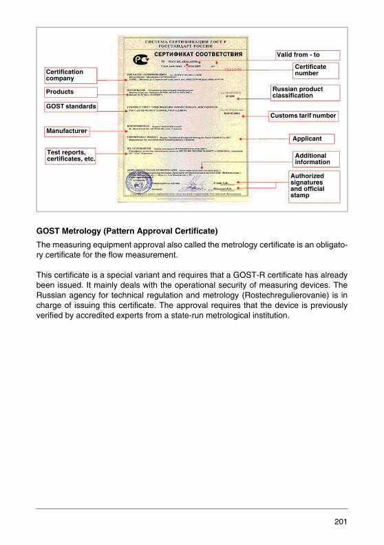
GOST Metrology (Pattern Approval Certificate)
The measuring equipment approval also called the metrology certificate is an obligato-ry certificate for the flow measurement.
This certificate is a special variant and requires that a GOST-R certificate has alreadybeen issued. It mainly deals with the operational security of measuring devices. TheRussian agency for technical regulation and metrology (Rostechregulierovanie) is incharge of issuing this certificate. The approval requires that the device is previouslyverified by accredited experts from a state-run metrological institution.
Certification company
Products
GOST standards
Test reports, certificates, etc.
Valid from - to
Applicant
Certificate number
Russian product classification
Additional information
Authorized signatures and official stamp
Manufacturer
Customs tarif number
201
The registration includes the entry of the device in the database of the regulatory au-thority. The advantage is that an already registered device does not have to be re-reg-istered.
GOST Explosion Protection
The GOST-EX certificate is obligatory for explosion proof flowmeters. GOST-EX certi-fications are performed by accredited Russian test laboratories. Approvals of this kindare always required when products with ATEX approval are imported into Russia. Theapproval is based on the valid EC type examination certificates in accordance withATEX95.
The approval procedure includes, among other things, the inspection of the manufac-turer plant and a type inspection of specific selected product types through the com-missioned Russian certification agency. The certificate has a validity period of up tothree years. Prolongation of the validity period must be requested in good time beforeits expiry. The entire approval procedure will take approximately three to four months.
202
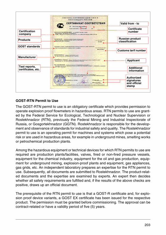
GOST-RTN Permit to Use
The GOST-RTN permit to use is an obligatory certificate which provides permission tooperate explosion proof flowmeters in hazardous areas. RTN permits to use are grant-ed by the Federal Service for Ecological, Technological and Nuclear Supervision orRostekhnadzor (RTN), previously the Federal Mining and Industrial Inspectorate ofRussia, or Gosgortekhnadzor (GGTN). Rostekhnadzor is responsible for the develop-ment and observance of standards for industrial safety and quality. The Rostekhnadzorpermit to use is an operating permit for machines and systems which pose a potentialrisk or are used in hazardous areas, for example in underground mines, smelting worksor petrochemical production plants.
Among the hazardous equipment or technical devices for which RTN permits to use arerequired are production plants/facilities, valves, fired or non-fired pressure vessels,equipment for the chemical industry, equipment for the oil and gas production, equip-ment for underground mining, explosion-proof plants and equipment, gas appliances,gas grids, etc. An independent laboratory prepares an expertise for the RTN permit touse. Subsequently, all documents are submitted to Rostekhnadzor. The product-relat-ed documents and the expertise are examined by experts. An expert then decideswhether all safety requirements are fulfilled and, if the results of the above checks arepositive, draws up an official document.
The prerequisite of the RTN permit to use is that a GOST-R certificate and, for explo-sion proof device variants, a GOST EX certificate has been issued for the respectiveproduct. The permission must be granted before commissioning. The approval can becontract-related or have a validity period of five (5) years.
Certification company
Products
GOST standards
Test reports, certificates, etc.
Valid from - to
Applicant
Certificate number
Russian product classification
Additional information
Authorized signatures and official stamp
Manufacturer
Customs tarif number
203
204

3.5.2 Belarus, Ukraine and Kazakhstan
Certification for Belarus
Generally speaking the certification procedure for Belarus is similar to those in theCommonwealth of Independent States (CIS) and the Russian Federation. There are,however, some differences which must be taken into account in order to provide for anunproblematic and quick exportation of products to Belarus.
The official certification institution of Belarus is the Department on Supervision of SafeWorks Realization in the Industry of the Ministry for Emergency Situations of BelarusRepublic (Gospromnadzor). Like its Russian counterpart Gospromnadzor grants certif-icates on the basis of an expertise submitted by accredited experts after having com-pleted the accreditation procedure. In their expertise the experts confirm that the prod-uct to be imported complies with the regulatory rules of Belarus. As a rule, inspectionson site are required.
Mandatory certificates for flowmeters are – similar to Russia – the metrology certificateand the EX-Promatomnadzor certificate which unites the Russian GOST-EX certificateand the RTN permit to use in a single certificate.
Certification for Ukraine
The regulatory rules for Ukraine regarding the import of foreign products are basicallythe same as for the Russian Federation (Russia), but may differ in details. The equiv-alent to the GOST-R certificate is the UkrSEPRO certificate which, for the time being,is considered as not obligatory for flowmeters. Moreover, the following certificates maybe required in both Ukraine and the Russian Federation (Russia) for the importation offlowmeters in individual cases:
• Metrology certificate• GOST-EX certificate with expert decision• DVSC certificate (EX operating permit)
In Ukraine the certification procedure itself is more complex than in Russia and requiresadditional expert knowledge regarding the national decrees and laws in order to be ableto successfully complete the certification process.Another difference is the proceedingof the accredited test institutes. The majority of the required tests and examinations areperformed directly at the manufacturer's site. Usually, the experts must visit the com-pany.
205
Certification for Kazakhstan
The regulatory rules for Kazakhstan regarding the import of foreign products are basi-cally the same as for the Russian Federation (Russia), but may differ in details. Theequivalent for the GOST-R certificate is the GOST-K certificate. Moreover, the follow-ing certificates are required in both Kazakhstan and the Russian Federation (Russia)for the import and marketing of flowmeters:
• GOST-K Certificate: may be obtained on site by own sales representatives. • EX Permit to Use and EX Permission: unites the GOST-EX certificate and the RTN
permit to use according to the Russian standard. • Metrology Certificate: is issued by the KasInMetr authority. The certification procedure itself is more complex than in Russia and requires addition-al expert knowledge regarding the national decrees and laws. Moreover, higher certifi-cation costs have to be expected. Another difference is the proceeding of the accredit-ed test institutes. The majority of the required tests and examinations are performeddirectly at the manufacturer's site. Usually, the experts must visit the company.
206

3.6 SIL - Functional Safety Standards
The standards IEC 61508 and IEC 61511 provide methods for the risk assessment ofsafety-related systems. They define four safety integrity levels and describe measuresfor mastering the risks of plant parts. In order to determine the SIL level of a device, allfield devices are subjected to the demanding test conditions and analyses of the IEC.
With the Council Directive 96/82/EC (“Seveso II Directive”) the European Union hascreated the legal basis for the operation of plants with hazard potential. The Germanimplementation of the Directive 96/82/EC in national legislation is the Hazardous Inci-dent Ordinance in the Federal Act for the Protection against Imissions (12th. BImSchV)as of April 26, 2000.
By July 31, 2004, the Hazardous Incident Ordinance referred to the standardsDIN 19250 and 19251 with the requirements classes 1 - 8 for the construction of safety-related process control equipment. Since August 1, 2004, the Hazardous Incident Or-dinance has referred to DIN EN 61508 and DIN EN 61511 which match the contents ofthe IEC 61508 / IEC 61511 standards. They define four safety integrity levels (SIL1 toSIL4) which describe the measures to be taken for mastering the risks of plant partsand to which the field devices and actuators must comply.
In order to be able to evaluate whether or not a device is suited for a safety chain withspecific SIL requirements, the field devices are analyzed and verified in co-operationwith an independent institution.
The hardware structure of the electronics is assessed by performing a Failure Mode,Effect and Diagnostics Analysis (FMEDA)Considering the (electro)mechanic compo-nents, the failure rates of a device, for example a flowmeter, can then be determined.Basically, three parameters are calculated from the FMEDA for this purpose: the Hard-ware Failure Tolerance (HFT), the Safe Failure Fraction (SFF) and the Probablility ofFailure on Demand (PFD).
The software development process of SIL-certified flowmeters is subject to IEC 61508and, thus, is even beyond the requirements of IEC 61511.
Additionally, further general safety assessments of the field devices are performed. Inthe SIL Declaration of Conformity provided by the manufacturer in order to support thecustomer in selecting the appropriate devices for safety systems, the specified classi-fication always refers to the lowest SIL level.
207

For the purpose of achieving safe plant operation, in another step according to the IECregulations the entire safety systems consisting of the sensor/transmitters, control unitand actuator is considered and the SIL classification is made. Prior to the design andcalculation of the safety system a SIL assessment is performed for determining thesafety integrity level (e.g. SIL2) with which the safety system must comply.
ABB offers a special software which covers all aspects of plant certification from theSIL assessment to the design and calculation of the safety systems in accordance withIEC 61508. The software also logs and saves all decisions and calculation bases.
In daily operation of a plant, it is also necessary to check the safety systems in termsof their safety functions on a regular basis and record the results. To achieve this, indi-vidual test routines must be defined, executed and logged. A complex process, but abig advantage for the health, safety and environment.
In addition to its comprehensive instrumentation portfolio, ABB also offers a specialsoftware that manages the test routines and test results required in IEC 61508 for allsafety systems and provides them for statistics.
208

3.7 Pressure Equipment Directive 97/23/EC
Introduction
The Council Directive for Pressure Equipment 97/23/EC (Pressure Equipment Direc-tive, PED) belongs to a series of newly designed, harmonized EC directives intendedto remove the technical barriers to free trade within the Community. At the same timeit is a first step towards the product harmonization of pressure equipment with respectto the design, manufacturing and conformity assessment. The observance of specificsafety requirements is of special importance.
The Council Directive 97/23/EC has been published on July 9, 1997 in the Official Jour-nal of the European Community (OJ L181) and must be applied in all EC MemberStates since 2002, after having been implemented in national legislation.
Compliance with the provisions of this EC Directive, which includes several amend-ments with respect to the placement of pressure equipment on the market, is the re-sponsibility of the manufacturer, confirmed by the attachment of the CE mark and theissuance of the EC Declaration of Conformity.
Scope
The Pressure Equipment Directive applies to the placement on the market and com-missioning of pressure equipment and assemblies thereof with a maximum allowablepressure greater than 0.5 bar. It does not apply to the monitoring and repeated routinechecks of this equipment during operation. Pressure equipment covered by the scopeof this directive includes vessels, piping, safety accessories and pressure accessoriesand assemblies consisting of pressure equipment. A list of devices that are beyond thescope of the directive is found in the directive itself.
Essential Safety Requirements
According to the safety considerations of the Pressure Equipment Directive the obliga-tions arising from the essential requirements listed in Annex I apply to pressure equip-ment and assemblies where the corresponding hazard exists. The safety requirementsare compulsory. The manufacturer is under obligation to conduct a risk assessment inorder to identify the hazards which apply to his equipment on account of pressure. Thepressure equipment must be designed and constructed taking account of this analysis.The essential requirements are to be interpreted and applied in such a way as to takeaccount of the state of the art and current practice at the time of design and manufac-ture as well as of technical and economic considerations. Pressure equipment must bedesigned, manufactured and checked, and if applicable equipped and installed, in sucha way as to ensure its safety when put into service in accordance with the manfuactur-er's instructions.
As a result, measuring devices that are covered by the scope of the Pressure Equip-ment Directive but do not meet its requirements must not be placed on the market.
209
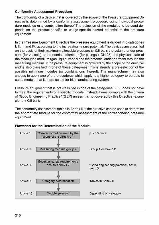
Conformity Assessment Procedure
The conformity of a device that is covered by the scope of the Pressure Equipment Di-rective is determined by a conformity assessment procedure using individual proce-dure modules or a combination thereof.The selection of the modules to be used de-pends on the product-specific or usage-specific hazard potential of the pressureequipment.
In the Pressure Equipment Directive the pressure equipment is divided into categoriesI, II, III and IV, according to the increasing hazard potential. The devices are classifiedon the basis of their maximum allowable pressure (> 0.5 bar), the volume under pres-sure (for vessels) or the nominal diameter (for pipings > DN 25), the physical state ofthe measuring medium (gas, liquid, vapor) and the potential endangerment through themeasuring medium. If the pressure equipment is covered by the scope of the directiveand is also classified in one of these categories, this is already a pre-selection of thepossible minimum modules (or combinations thereof). The manufacturer may alsochoose to apply one of the procedures which apply to a higher category to be able touse a module that is more suited for his manufacturing system.
Pressure equipment that is not classified in one of the categories I - IV does not haveto meet the requirements of a specific module. Instead, it must comply with the criteriaof “Good Engineering Practice” (GEP) unless it is not covered by this Directive (exam-ple: p < 0.5 bar).
The conformity assessment tables in Annex II of the directive can be used to determinethe appropriate module for the conformity assessment of the corresponding pressureequipment.
Flowchart for the Determination of the Module
Article 1 Covered or not covered by thescope of the directive ?
p > 0.5 bar ?
Article 9 Measuring medium group ? Group 1 or Group 2
Article 3Essential safety requirements
acc. to Annex I ? “Good engineering practice”, Art. 3, Item. 3
Article 9 Category determination Tables in Annex II
Article 10 Module selection Depending on category
210
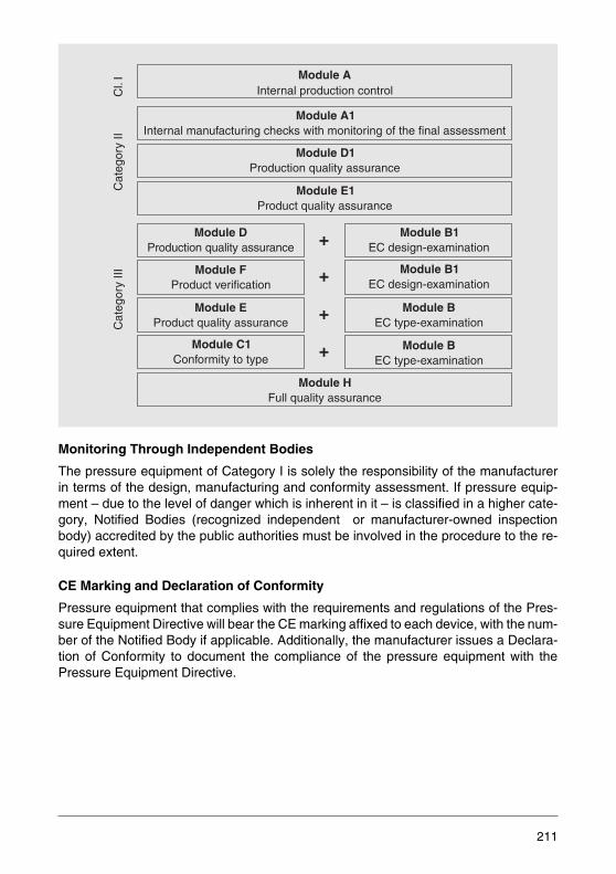
Monitoring Through Independent Bodies
The pressure equipment of Category I is solely the responsibility of the manufacturerin terms of the design, manufacturing and conformity assessment. If pressure equip-ment – due to the level of danger which is inherent in it – is classified in a higher cate-gory, Notified Bodies (recognized independent or manufacturer-owned inspectionbody) accredited by the public authorities must be involved in the procedure to the re-quired extent.
CE Marking and Declaration of Conformity
Pressure equipment that complies with the requirements and regulations of the Pres-sure Equipment Directive will bear the CE marking affixed to each device, with the num-ber of the Notified Body if applicable. Additionally, the manufacturer issues a Declara-tion of Conformity to document the compliance of the pressure equipment with thePressure Equipment Directive.
Module AInternal production control
Module A1Internal manufacturing checks with monitoring of the final assessment
Module D1Production quality assurance
Module E1Product quality assurance
Cl.
IC
ateg
ory
IIC
ateg
ory
III
Module DProduction quality assurance
Module FProduct verification
Module EProduct quality assurance
Module C1Conformity to type
Module B1EC design-examination
Module B1EC design-examination
Module BEC type-examination
Module BEC type-examination
Module HFull quality assurance
+
+
+
+
211

Implementation of the Pressure Equipment Directive by ABB
ABB consistently implements the Pressure Equipment Directive 97/23/EC for its flow-meters, among other devices, and is therefore entitled to issue the corresponding Dec-larations of Conformity. Flowmeters are pressure accessories covered by the scope ofthe Pressure Equipment Directive.
As a rule, ABB classifies its flowmeters in Category III, independently of their specificapplications. This category covers the highest potential level of danger which is possi-ble for piping components. This ensures that the maximum safety requirements interms of the design, manufacturing and conformity assessment procedure are takeninto account. Flowmeters with nominal diameters DN 25 or smaller also fulfill the basicrequirements of the Pressure Equipment Directive although they are not formally cov-ered by its scope.
Classification Example
Piping DN 100, PS = 32 bar, TS = 180 °C, liquid of Group 1, vapor pressure > 0.5 barabove atmospheric pressure
Fig. 3-12:
DN
PS
[bar
]
PS
· DN
=1000
PS
· DN
=3500
PS=0.5
DN
=25
DN
=10
0D
N=
100
DN
=35
0
-0.51
10
100
1000
0 1 10 25 100 3501000
212

3.8 Corrosion
Corrosion is defined as the destruction of materials through chemical reactions. Gen-erally, the concept is limited to a change of the structure of a metal caused by an aque-ous solution. This is electrolytic corrosion for which the generation of rust is a prime ex-ample.
Metals with their free electrons are good electrical conductors. The conductivity of cor-rosive aqueous solutions is small, the current transport is ionic. During corrosion, a pos-itive current flows into the liquid. This causes the positively charged metallic ions to mi-grate into the liquid. The intensity of this process is a function of the ionic mobility andit increases with increasing temperature and decreases with concentration increases.Also, voltage differentials augment the corrosion. That is why the non-noble metals,such as aluminum and iron, which are grouped at the negative end of the electromotiveseries, are severely attacked. Corrosion problems can be avoided by utilizing noblemetals.
Organic chemicals, plastics, also show destructive characteristics when they come incontact with aqueous solutions. In this case it is primarily substitution processes whichalter the material. Substitution is the replacement of an atom or atomic group by anoth-er atom or atomic group. A material with new chemical and physical characteristics isproduced. The resistance to the solution can deteriorate. In order to evaluate the largenumber of organic materials it is necessary to rely on the experiences of the manufac-turers which are summarized in corrosion resistance tables.
The corrosion resistance table (see Chapter 8) shows how the materials used by ABBwill react when they get in contact with chemical products.
213

3.9 Data Transmission
The primary task of the transmitter connected to the flowmeter sensor is is to producean output signal which is proportional to the measured value and which can be used byother secondary instruments connected to the transmitter (e.g.: indicators, recorders,controllers). As these secondary devices are universally installed, the output signalsmust be standardized.
With the advent of intelligent transmitters, electrical data systems have forged into theforefront. For the time being, however, analog signal transmission is still preferred.
Digital technology offers appreciable advantages:
• The number of electrical interconnections decreases dramatically because every out-put does not require its own leads.
• Communication is not limited to the transmission of the measuring signal. The dataexchange occurs in both directions which means that the access and setting of pa-rameters can be effected from the outside. An error diagnosis is possible at any time.
• The entire system can be expanded without great effort.
• Digital signals are not affected by external interference when they are transmitted viathe communication line.
3.9.1 Standardized Pneumatic Signal
Devices and systems with a pneumatic power supply are not used very often anymore.The reason for their decline is their limited capabilities when compared to digital tech-nology coupled with the large expenses incurred in providing the air supply and costlyinstallations.
214
3.9.2 Standardized Electrical Analog Signal
The most common standardized electrical signal is a direct current of 0 to 20 mA or 4to 20 mA. It is called an impressed direct current because it is independent of the elec-trical resistance up to a specific maximum load. The permissible load for flowrate trans-mitters is 750 or 1000 Ω, respectively.
3.9.3 Switch Outputs
There are two types of switch outputs. The continuous contact is used for status signalswith which an alarm condition or the reaching of a limit value can be indicated.
In the event of a dangerous condition, e.g during a device failure or for critical mea-sured values, an alarm is reported. The limit contact is of interest in terms of control,since its status could indicate possible changes in the course of the process. Examplesare the empty pipe detector contact, the signal for flow direction reversal and the max./min. conditions.
The pulse output has a completely different function. The generated pulses are signalsthat are proportional to the volume and can be integrated by a totalizer. In this mannera volume signal is generated from the flow rate. The totalizer indicates the total volumethat has flowed through the flowmeter during a specific time interval.
There are a number of methods to electrically design switch outputs. Relay contacts oroptocoupler outputs are passive. Current outputs or voltage pulse outputs are active.
215
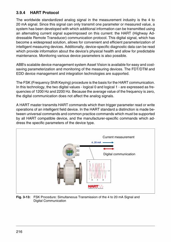
3.9.4 HART Protocol
The worldwide standardized analog signal in the measurement industry is the 4 to20 mA signal. Since this signal can only transmit one parameter or measured value, asystem has been developed with which additional information can be transmitted usingan alternating current signal superimposed on this current: the HART (Highway Ad-dressable Remote Transducer) communication protocol. This digital signal, which hasbecome a widespread solution, allows for convenient and efficient parameterization ofintelligent measuring devices. Additionally, device-specific diagnostic data can be readwhich provide information about the device's physical health and allow for predictablemaintenance. Monitoring various device parameters is also possible.
ABB's scalable device management system Asset Vision is available for easy and cost-saving parameterization and monitoring of the measuring devices. The FDT/DTM andEDD device management and integration technologies are supported.
The FSK (Frequency Shift Keying) procedure is the basis for the HART communication.In this technology, the two digital values - logical 0 and logical 1 - are expressed as fre-quencies of 1200 Hz and 2200 Hz. Because the average value of the frequency is zero,the digital communication does not affect the analog signals.
A HART master transmits HART commands which then trigger parameter read or writeoperations of an intelligent field device. In the HART standard a distinction is made be-tween universal commands and common practice commands which must be supportedby all HART compatible device, and the manufacturer-specific commands which ad-dress the specific parameters of the device type.
Fig. 3-13: FSK Procedure: Simultaneous Transmission of the 4 to 20 mA Signal and Digital Communication
Current measurement
Digital communication
216
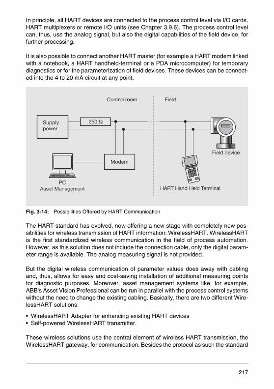
In principle, all HART devices are connected to the process control level via I/O cards,HART multiplexers or remote I/O units (see Chapter 3.9.6). The process control levelcan, thus, use the analog signal, but also the digital capabilities of the field device, forfurther processing.
It is also possible to connect another HART master (for example a HART modem linkedwith a notebook, a HART handheld-terminal or a PDA microcomputer) for temporarydiagnostics or for the parameterization of field devices. These devices can be connect-ed into the 4 to 20 mA circuit at any point.
Fig. 3-14: Possibilities Offered by HART Communication
The HART standard has evolved, now offering a new stage with completely new pos-sibilities for wireless transmission of HART information: WirelessHART. WirelessHARTis the first standardized wireless communication in the field of process automation.However, as this solution does not include the connection cable, only the digital param-eter range is available. The analog measuring signal is not provided.
But the digital wireless communication of parameter values does away with cablingand, thus, allows for easy and cost-saving installation of additional measuring pointsfor diagnostic purposes. Moreover, asset management systems like, for example,ABB's Asset Vision Professional can be run in parallel with the process control systemswithout the need to change the existing cabling. Basically, there are two different Wire-lessHART solutions:
• WirelessHART Adapter for enhancing existing HART devices• Self-powered WirelessHART transmitter.
These wireless solutions use the central element of wireless HART transmission, theWirelessHART gateway, for communication. Besides the protocol as such the standard
Field
Field device
HART Hand Held Terminal
Control room
Supplypower
250 Ω
Modem
PCAsset Management
217

also defines various security mechanisms which ensure availability and tap-proof wire-less signal transmission.
3.9.5 Fieldbus in Process Automation
Fieldbus systems are a communication medium for serial data exchange between de-centralized devices of the field level and the input peripherals of the process control lev-el. For process data acquisition in the field level not only intelligent measuring devicesand actuators with direct connections to the fieldbus are used but also intelligent re-mote I/O units as interface systems for conventional field devices.
Only two wires suffice for transmitting all relevant signals like input and output data, pa-rameters, diagnostic information and configuration schemes and - for additional appli-cations - the operating energy. If a field device has a high energy demand, this devicewill be supplied separately from the signal bus, i.e. a four-wire system is used insteadof a two-wire.
The use of a unique definition for the communication protocol allows the fieldbus to beopen to all field device vendors who use this protocol.In this manner it was possible toachieve interchangeability and also use the standard 4 to 20 mA signal for the fieldbustechnology.
Besides the considerably reduced cabling effort the fieldbus technology also providesother advantages. Every measured value is transmitted together with a status, an indi-cator for the reliability of the value and a module of the diagnostic capabilities of field-bus communication systems.
Standardized diagnostics and device-specific diagnostic information are available forall devices and communication components. Additionally, the measured value have anespecially high resolution as they are purely digital. Different transmission rates andconfiguration options for communication allow for perfect adaptation of the measure-ment and transmission operations to the process requirements.
After many years of successful use in industrial applications, the fieldbus technologieshave become a powerful, reliable and cost-saving alternative to conventional installa-tions with considerably more information.
218
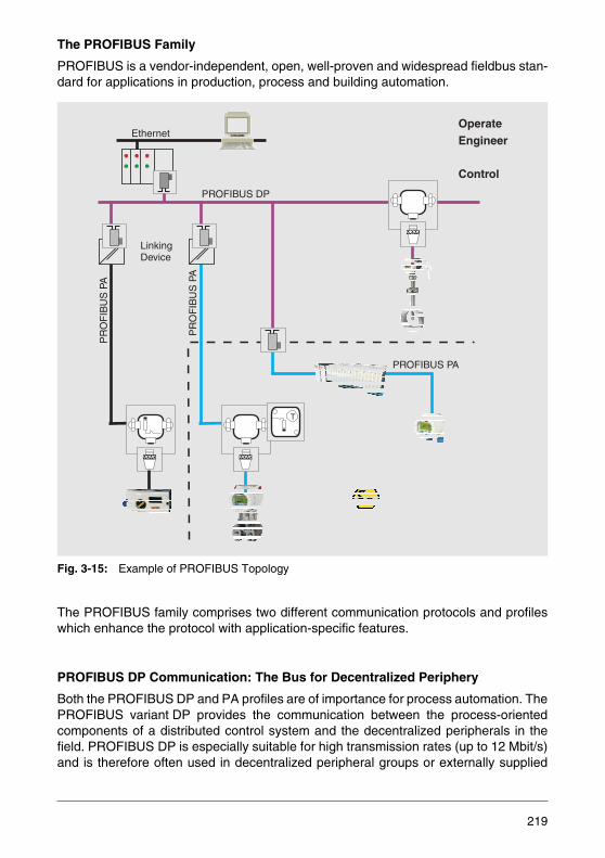
The PROFIBUS Family
PROFIBUS is a vendor-independent, open, well-proven and widespread fieldbus stan-dard for applications in production, process and building automation.
Fig. 3-15: Example of PROFIBUS Topology
The PROFIBUS family comprises two different communication protocols and profileswhich enhance the protocol with application-specific features.
PROFIBUS DP Communication: The Bus for Decentralized Periphery
Both the PROFIBUS DP and PA profiles are of importance for process automation. ThePROFIBUS variant DP provides the communication between the process-orientedcomponents of a distributed control system and the decentralized peripherals in thefield. PROFIBUS DP is especially suitable for high transmission rates (up to 12 Mbit/s)and is therefore often used in decentralized peripheral groups or externally supplied
T
OperateEngineer
Control
PROFIBUS DP
Ethernet
LinkingDevice
PR
OF
IBU
S P
A
PR
OF
IBU
S P
A
PROFIBUS PA
219
field devices such as positioners or flowmeters. PROFIBUS DP/V1 additionally allowsfor acyclic communication and, thus, the use of FDT/DTM or EDD tools for the param-eterization and monitoring of devices.
PROFIBUS PA Communication: Expansions for Process Automation
PROFIBUS PA was specifically developed for use with process technology. Intrinsicsafety and supply of the field devices via the two-wire bus line are possible and complywith the IEC 61158-2 Standard (Manchester Bus Powered – MBP Physics). This vari-ant is used for communication with two-wire supplied measuring devices and actuatorsin the field. PROFIBUS PA uses an expanded form of the DP protocol. The deviceproperties and behavior are described by so-called profiles and defined in the standard.Using coupler modules (segment couplers, gateways, linking devices) the PA bus linesare integrated in the PROFIBUS DP network. This ensures that all information in theentire PROFIBUS system (with DP and PA profile devices) is available in a consistentnetwork.
PROFINET
This additional communication protocol of the PROFIBUS family allowed for a success-ful start into the age of the industrial Ethernet. The technology can be used in differentmanners:
• As a bus system (mainly used in production automation)
• As a backbone network for heterogeneous networks with consistent basic communi-cation (connection to different network types via a proxy server)
So far, PROFINET has not yet gained noteworthy importance in the field of process au-tomation.
3.9.6 FOUNDATION Fieldbus
This fieldbus technology has been introduced approximately 10 years ago. It is mainlyused in America and provides two variants:
– HSE - High Speed Ethernet. This variant so far has not yet been applied very of-ten in industrial environments. Only controllers and linking devices use this proto-col.
– FF-H1. Similar to the PROFIBUS PA profile this protocol uses the MBP (Manchester coding with Bus Powering) physics and, thus, allows for direct pow-ering of the devices via the bus cable. A characteristic feature of H1 is the capa-bility to allow the field devices to take over and process simple control tasks by themselves (“control in the field”). This means that the network intelligence is in parts transferred to the field level. This option requires deterministic operation of the H1 protocol. Another typical feature of the FOUNDATION Fieldbus is the abil-ity to transmit alarms with a time stamp.
220
3.10 Calibration and Official Verification
3.10.1 Why Calibrate?
In the company the requirement for rigorous traceability of the test equipment to nation-al standards by calibrations to assure that everyone uses the “same measurementstick”, is essential both for suppliers who manufacture the products and for users whoinstall these parts with other parts, due to increasing national and international divisionof work and the resultant requirement for interchangeability.
In addition to the technical reasons, there are also legal aspects. The relevant direc-tives and regulations must also be observed together with contractual obligations withthe purchaser of the products (assurance of the quality of the product) and the respon-sibility to only bring products to the market place the safety of which is not compromisedby faults when they are used as intended. As far as contractual responsibilities for theaccuracy of the measuring devices were agreed, a nonfulfillment of these requirementsis a failure of a guaranteed property.
Proof of the selection of adequate test equipment and its proper operation within thescope of product liability is of great importance within the framework of product liability,because a systematic and completely documented test equipment monitoring in com-bination with continuous proof of the adequacy of the test equipment for the task is es-sential for a possible exoneration proof.
3.10.2 Terms and Definitions
Measuring DeviceA device that is to be used for measurements, either as a stand-alone unit or togetherwith other equipment.
Standard (Reference)Material measure, measuring device, reference material or measuring equipment in-tended to represent, maintain or reproduce a unit or one or more quantity values.
MeasurementThe totality of activities for determining a quantity value (represented as the product ofa numerical value and a unit, e.g. 1.23 m³/h).
221

CalibrationThe determination of the relationship between the specified values of a measuring de-vice and the values specified by standards for given conditions.
AdjustmentIn the context of measurement adjustment means setting or balancing a measuring de-vice in such a way that the measuring deviation is a small as possible.
Official VerificationVerification and marking of a measuring device and/or issuing of a calibration certificatefor a measuring device to determine and confirm that the device complies with the legalrequirements. This is to certify that it can be duly expected that the values measuredby this measuring device will lie within the error limits (within the re-calibration period)provided that the measuring device is handled in accordance with the recognized rulesof engineering.
Measurement UncertaintyParameter allocated to the measuring result and which specifies the spread of the(measured) values that can reasonably be assigned to the measured variable.
TraceabilityCapability of a measuring device (or the values of a standard) to be related to the ap-propriate normals, usually international or national standards, through an uninterruptedchain of reference measurements with the specified measuring uncertainties.
3.10.3 Methods of Flow Calibration
The commonly used measurement methods are:
Volumetric MethodProcedure to measure the volume flow rate of a liquid using a calibrated volume mea-surement tank (bell prover) and measuring the fill time.
Gravimetric MethodThis method is comparable to the volumetric method. In this case, however, the volumeof the liquid is measured by weighing, taking into account the density and the displacedamount of air.
222
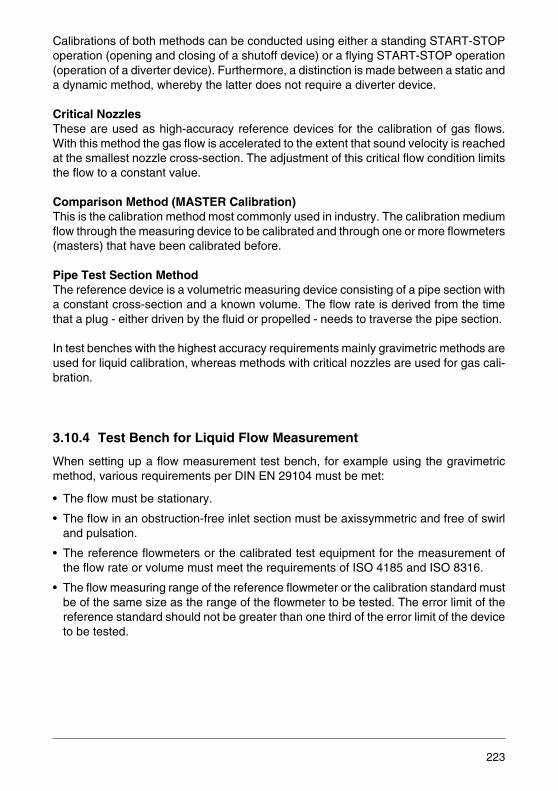
Calibrations of both methods can be conducted using either a standing START-STOPoperation (opening and closing of a shutoff device) or a flying START-STOP operation(operation of a diverter device). Furthermore, a distinction is made between a static anda dynamic method, whereby the latter does not require a diverter device.
Critical NozzlesThese are used as high-accuracy reference devices for the calibration of gas flows.With this method the gas flow is accelerated to the extent that sound velocity is reachedat the smallest nozzle cross-section. The adjustment of this critical flow condition limitsthe flow to a constant value.
Comparison Method (MASTER Calibration)This is the calibration method most commonly used in industry. The calibration mediumflow through the measuring device to be calibrated and through one or more flowmeters(masters) that have been calibrated before.
Pipe Test Section MethodThe reference device is a volumetric measuring device consisting of a pipe section witha constant cross-section and a known volume. The flow rate is derived from the timethat a plug - either driven by the fluid or propelled - needs to traverse the pipe section.
In test benches with the highest accuracy requirements mainly gravimetric methods areused for liquid calibration, whereas methods with critical nozzles are used for gas cali-bration.
3.10.4 Test Bench for Liquid Flow Measurement
When setting up a flow measurement test bench, for example using the gravimetricmethod, various requirements per DIN EN 29104 must be met:
• The flow must be stationary.
• The flow in an obstruction-free inlet section must be axissymmetric and free of swirland pulsation.
• The reference flowmeters or the calibrated test equipment for the measurement ofthe flow rate or volume must meet the requirements of ISO 4185 and ISO 8316.
• The flow measuring range of the reference flowmeter or the calibration standard mustbe of the same size as the range of the flowmeter to be tested. The error limit of thereference standard should not be greater than one third of the error limit of the deviceto be tested.
223

• The measuring equipment and the reference standard must be described in detail,including the traceability of the reference standard and the uncertainty of the measur-ing setup. The calculation of the uncertainty of the flow measurement must complywith ISO 5168, ISO 7066-1 and ISO 7066-2.
• The sensor must be installed between a straight, undisturbed inlet section of at least10 x D and an undisturbed outlet section of at least 5 x D. If swirl-free velocity profilesare required, flow straighteners must be installed.
• During the measurement, the sensor must be completely filled with liquid.
Additionally, the physical characteristics of the measuring medium, for example, den-sity and viscosity, must also be considered. Analogy calculations can be made usingthe Reynolds number which takes into account different flow regimes. Naturally, theother equipment on the test bench also have accuracies, which is so good that theyonly have minimal impact on the flow rate measurement results.
Fig. 3-16: Test Bench for Gravimetric Calibration and Comparison Calibration Methods
In the schematic diagram of a liquid test bench shown in Fig. 3-16 the water flowsthrough two comparison standards (2) which cross-check each other. The flowmeterbeing calibrated (3) is installed in a long, undisturbed pipe section. The control valve(4) and the pump (1) determine the set flow rate. The water can then either be returneddirectly to the supply reservoir (8) or by actuating the diverter (7) into the tank (5), whereits mass can be measured. The scale arrangement (6) itself is calibrated in periodic in-tervals with weights by the Office of Weights and Measures.
M M
M M M
MM
4 Test meter
Flow to tank
Flow from tank10
7
6
95 8
4
3
12
2 Comparison standard
5 Control valve6 Container7 Weighing cells8 Leak control Pt100
Supply reservoir9 Diverter
3 Flow straightener
1 Pump
10
224
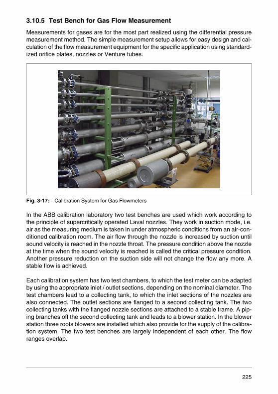
3.10.5 Test Bench for Gas Flow Measurement
Measurements for gases are for the most part realized using the differential pressuremeasurement method. The simple measurement setup allows for easy design and cal-culation of the flow measurement equipment for the specific application using standard-ized orifice plates, nozzles or Venture tubes.
Fig. 3-17: Calibration System for Gas Flowmeters
In the ABB calibration laboratory two test benches are used which work according tothe principle of supercritically operated Laval nozzles. They work in suction mode, i.e.air as the measuring medium is taken in under atmospheric conditions from an air-con-ditioned calibration room. The air flow through the nozzle is increased by suction untilsound velocity is reached in the nozzle throat. The pressure condition above the nozzleat the time when the sound velocity is reached is called the critical pressure condition.Another pressure reduction on the suction side will not change the flow any more. Astable flow is achieved.
Each calibration system has two test chambers, to which the test meter can be adaptedby using the appropriate inlet / outlet sections, depending on the nominal diameter. Thetest chambers lead to a collecting tank, to which the inlet sections of the nozzles arealso connected. The outlet sections are flanged to a second collecting tank. The twocollecting tanks with the flanged nozzle sections are attached to a stable frame. A pip-ing branches off the second collecting tank and leads to a blower station. In the blowerstation three roots blowers are installed which also provide for the supply of the calibra-tion system. The two test benches are largely independent of each other. The flowranges overlap.
225
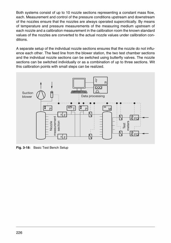
Both systems consist of up to 10 nozzle sections representing a constant mass flow,each. Measurement and control of the pressure conditions upstream and downstreamof the nozzles ensure that the nozzles are always operated supercritically. By meansof temperature and pressure measurements of the measuring medium upstream ofeach nozzle and a calibration measurement in the calibration room the known standardvalues of the nozzles are converted to the actual nozzle values under calibration con-ditions.
A separate setup of the individual nozzle sections ensures that the nozzle do not influ-ence each other. The feed line from the blower station, the two test chamber sectionsand the individual nozzle sections can be switched using butterfly valves. The nozzlesections can be switched individually or as a combination of up to three sections. Witthis calibration points with small steps can be realized.
Fig. 3-18: Basic Test Bench Setup
P T
FQ
FQ
P M
F
F
R
Suctionblower
Noz
zle
mea
sure
men
tse
ctio
n
Test
met
ers
Data processing
226

3.10.6 Approvals of Test Benches and Products
DAkkS Accreditation
ABB has a DAkkS calibration laboratory for flow measurement. This calibration labora-tory is accredited and monitored by Deutsche Akkreditierungsstelle GmbH (DAkkS, for-merly DKD). DAkkS has been founded by the Federal Republic of Germany, represent-ed by the BMWi (Federal Ministry of Economics and Technology). The issued DAkkScalibration certificates are proof of the traceability to the national standards as requiredin the DIN EN ISO 9000 and DIN EN ISO 17025 series of standards. Calibrations inDAkkS laboratories provide the user assurance of the reliability of the measurement re-sults, increase the confidence of the customer and provide competitiveness in the na-tional and international markets. They are the technological basis for the measurementand test equipment monitoring within the framework of quality assurance.
In the course of globalization the international reciprocal recognition of calibration cer-tificates is getting more and more important. Within in Europe, this is governed by amultilateral agreement (MLA) of the European Co-operation for Accreditation (EA),worldwide through the International Laboratory Accreditation Cooperation (ILAC).DAkkS calibration certificates are recognized by all signatory states of this agreement.
227
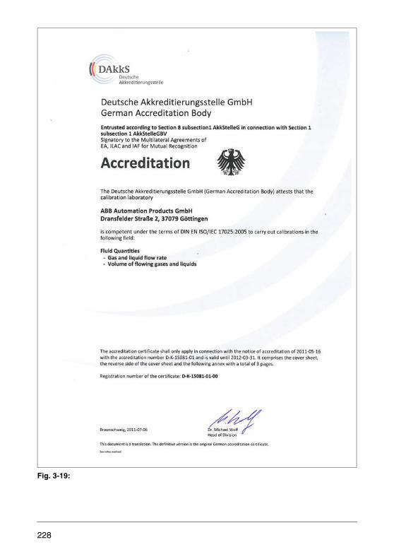
Fig. 3-19:
228

Testing of Measurement Devices for the Volume Measurement of Flowing Liquids (Certification Approval)
Various ABB test benches have received from PTB (German National Institute of Tech-nology and Science) the approval to calibrate approved certified measuring devices(see next section) as well as to perform technical tests in the presence of an officialfrom the Office of Weights and Measures. The calibration certificates issued (withoutmeasurement specifications, according to the calibration regulations) or test certifi-cates MEN (with measurement specifications) are proof of the traceability to nationalstandards.
Type Examination Approval for Intrastate Certified Calibrations (Germany)
In order to be able to calibrate a measuring device, it is not enough to have an approvedtest bench. The flowmeters themselves must also be approved by PTB for intrastateofficial verification in order to certify that they comply with the requirements of the cali-bration regulations. The Calibration Regulation EO 5 makes a distinction between dif-ferent measuring media and evaluates them individually. For this reason, the approvalincludes not only the device type, but also the nominal diameter, flow range and mea-suring medium. ABB has received the following approvals:
Approved and calibrated devices can be identified by their special name plate:
Fig. 3-20: Name Plate of Measuring Device with Approval for Certified Calibration of Water/Waste Water (Germany, only)
Approval Range Device Type Nominal Diameter Range
Cold water/waste water 6.221 Electromagnetic flowmeter
DN 25...DN 2000
Liquids other than waterfor example: • Milk• Brine• Beer• Wort• Beverage concentrate• Chemical liquids
5.721 Electromagnetic flowmeter
DN 25...DN 40, DN 65, DN 80DN 100...DN 150DN 25...DN 100DN 50...DN 100DN 25DN 25...DN 150
229
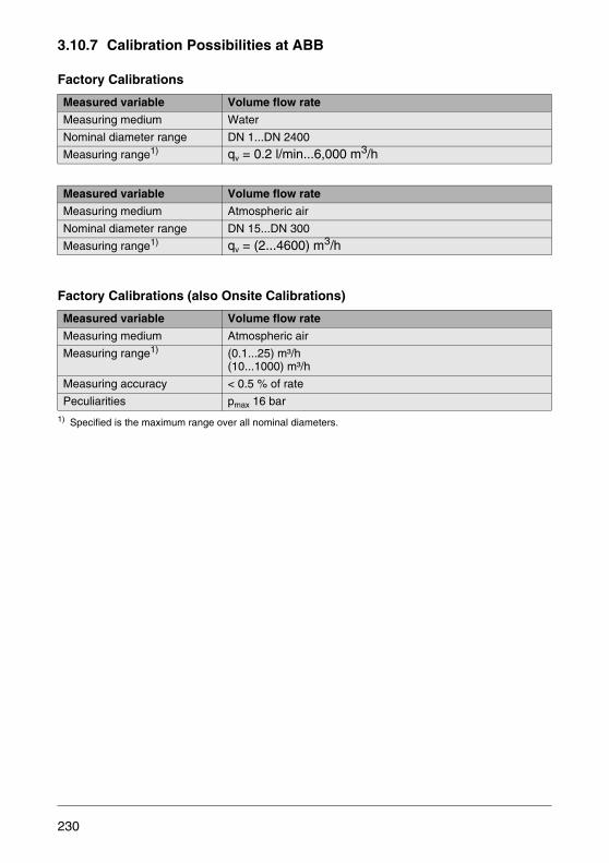
3.10.7 Calibration Possibilities at ABB
Factory Calibrations
Factory Calibrations (also Onsite Calibrations)
1) Specified is the maximum range over all nominal diameters.
Measured variable Volume flow rate
Measuring medium Water
Nominal diameter range DN 1...DN 2400
Measuring range1) qv = 0.2 l/min...6,000 m3/h
Measured variable Volume flow rate
Measuring medium Atmospheric air
Nominal diameter range DN 15...DN 300
Measuring range1) qv = (2...4600) m3/h
Measured variable Volume flow rate
Measuring medium Atmospheric air
Measuring range1) (0.1...25) m³/h(10...1000) m³/h
Measuring accuracy < 0.5 % of rate
Peculiarities pmax 16 bar
230
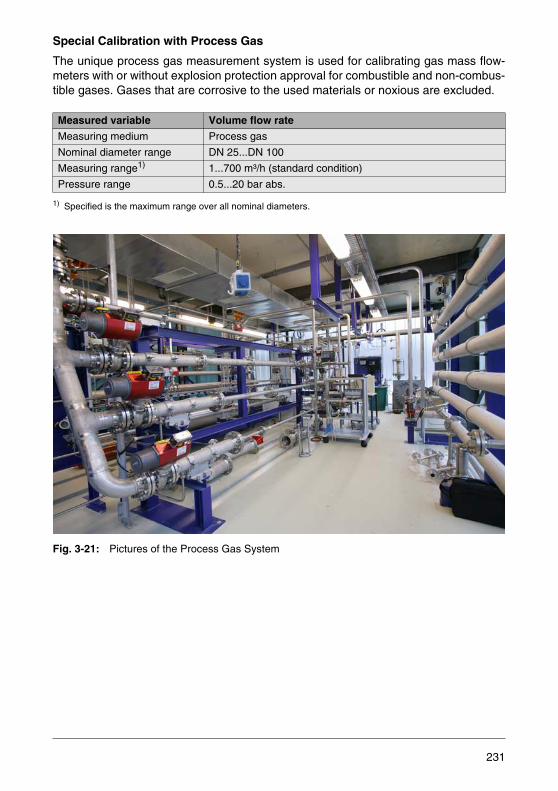
Special Calibration with Process Gas
The unique process gas measurement system is used for calibrating gas mass flow-meters with or without explosion protection approval for combustible and non-combus-tible gases. Gases that are corrosive to the used materials or noxious are excluded.
1) Specified is the maximum range over all nominal diameters.
Fig. 3-21: Pictures of the Process Gas System
Measured variable Volume flow rate
Measuring medium Process gas
Nominal diameter range DN 25...DN 100
Measuring range1) 1...700 m³/h (standard condition)
Pressure range 0.5...20 bar abs.
231
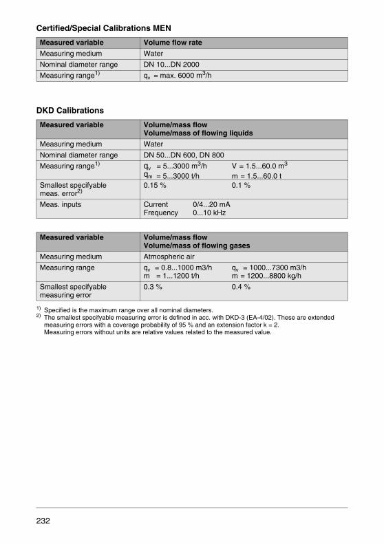
Certified/Special Calibrations MEN
DKD Calibrations
1) Specified is the maximum range over all nominal diameters.2) The smallest specifyable measuring error is defined in acc. with DKD-3 (EA-4/02). These are extended
measuring errors with a coverage probability of 95 % and an extension factor k = 2. Measuring errors without units are relative values related to the measured value.
Measured variable Volume flow rate
Measuring medium Water
Nominal diameter range DN 10...DN 2000
Measuring range1) qv = max. 6000 m3/h
Measured variable Volume/mass flowVolume/mass of flowing liquids
Measuring medium Water
Nominal diameter range DN 50...DN 600, DN 800
Measuring range1) qv = 5...3000 m3/h V = 1.5...60.0 m3 qm = 5...3000 t/h m = 1.5...60.0 t
Smallest specifyablemeas. error2)
0.15 % 0.1 %
Meas. inputs Current 0/4...20 mAFrequency 0...10 kHz
Measured variable Volume/mass flowVolume/mass of flowing gases
Measuring medium Atmospheric air
Measuring range qv = 0.8...1000 m3/h qv = 1000...7300 m3/hm = 1...1200 t/h m = 1200...8800 kg/h
Smallest specifyablemeasuring error
0.3 % 0.4 %
232

3.10.8 Measuring Instruments Directive (MID)
The Measuring Instruments Directive MID is a European directive that describes theprerequisites for placing on the market and putting in use measuring devices for legalmetrology (calibration) The directive was adopted by the European Parliament and in-corporated by the Member States of the European Union into national legislation. InGermany this resulted in the amendment of the already existing Verification Act.
Due to the harmonized standards in Europe, an approval is recognized in all MemberStates of the EU. The requirements in terms of the device technology are only roughlyoutlined in the MID, in order not to enforce technological restrictions. For detailed infor-mation please refer to the recommendations of the OIML (Organisation Internationalede Métrologie Légale).
For the conformity assessment different module combinations are possible:
Tab. 3-10: Overview of Module Combinations
MID Chronology and Transitional Period
The MID was adopted by the European Parliament in 2004 and had to be incorporatedinto national legislation within two years (by October 30, 2006, at the latest).
Type examination approvals issued before this date will be recognized for re-calibrationfor up to ten years after this deadline (i.e. until October 29, 2016).
Manufacturer Production Phases
Conformity Assessment
Modules B + F Modules B + D Module G (not for Water Meters)
Module H1
DevelopmentDesign
Unit Verification
Design ExaminationType Type Examination
(B)Type Examination
(B)
Series Production Quality Assurance
ofProduction Process (D)
Full Quality Assurance
Final Product
Product Verfication (F)
Declaration of Conformity and CE Marking
233

3.10.9 OIML (Organisation Internationale de Métrologie Légale)
The OIML is the International Organization for Legal Metrology having seat in Paris,France. It has already been existing for many years and has published various recom-mendations and documents for the worldwide standardization of the legal metrology.The OIML has a close cooperation with the PTB (German National Institute of Technol-ogy and Science).
OIML Recommendation R49 is valid for cold water meters, whereas flowmeters for liq-uids other than water fall under OIML Recommendation R117.
OIML R49 - Flowmeters for Cold Water
This directive describes the technical requirements on the device, the prerequisites forapproval and the tests to be performed (type examinations and routine tests). Theseinclude, for example:
– Accuracy classes (1 % and 2 %)– Measuring ranges in fixed steps– Flow ranges Q1 to Q4 (minimum flow to overload flow)– Flow measurement points, mounting position, inlet/outlet sections– Volume indication– Functional tests of devices with electronic equipment (e.g. EMC, vibration, tem-
perature)
OIML R117 - Flow Measurement of Liquids other than Water
This directive describes the technical requirements on the flowmeter and the entiremeasuring system, the prerequisites for approval and the tests to be performed (typeexaminations and routine tests). These include, for example:
– Various accuracy classes, depending on the measuring medium and application– Measuring ranges in fixed steps– Flow ranges Qmin to Qmax, with fixed ratio– Flow measurement points, mounting position, inlet/outlet sections– Indication of volume flow and mass flow (conversion requires special approval
procedure)– Functional tests of devices with electronic equipment (e.g. EMC, vibration, tem-
perature)– Suitability of the entire measuring system (e.g. pump, filter, gas separator)
234
4 Device Selection Criteria
By comparing the individual characteristics of volume totalizers and flowmeters, whichmust be considered from different points of view, this section of the manual attempts tocompile the most interesting aspects for instrument selection in order to provide a guideto the user. The various criteria are assembled in tables so that the applicability maybe readily ascertained for a particular situation.
Naturally it is not possible within the framework of this publication to be all encompass-ing.There are always special designs for individual applications, and the sizes and val-ues listed here are merely snapshots representing the current state of the art. They willcertainly be updated as technology continues to evolve.
Unfortunately, the initial cost is often the essential selection criterion. Lifecycle costs,for example for the preparation of the installation site, installation and maintenance, areoften considered as being of low priority or neglected for the most part. Additionally per-haps, considerations in terms of the long-term stability may play an important role indevice selection. The following comparison is intended to provide assistance in thisregard.
235
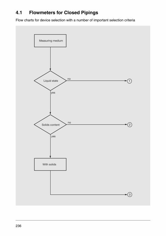
4.1 Flowmeters for Closed Pipings
Flow charts for device selection with a number of important selection criteria
3
2
1Liquid state
Measuring medium
With solids
no
no
yes
yes
Solids content
236

Lobed impellergas totalizer
Materialselection
Chemicallyaggressive
Thermal mass
Gas
Turbine
Diff. pressure
VFM
Coriolis mass
SFM
VAF
Inlet/outletsection
1
In addition to totalizer,is flow measurement required?
no
yes
yes
no
no no
yes
SFM Swirl flowmeterVAF Variable area flowmeterVFM Vortex flowmeter
Inlet/outletsection
237
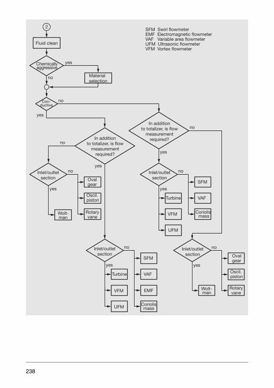
yes
2
yes
yes
no
no
no
yes
yes
no
yes
no
yes
no
yes
no
no
Fluid clean
Materialselection
Chemicallyaggressive
Con-ductive
In additionto totalizer, is flow
measurementrequired?
Inlet/outletsection
Wolt-man
Wolt-man
Coriolismass
SFM
VAF
Coriolismass
SFM
VAF
EMF
Turbine
UFM
VFM
Turbine
UFM
VFM
Ovalgear
Rotaryvane
Oscil.piston
In additionto totalizer, is flow
measurementrequired?
Inlet/outletsection
Inlet/outletsection
Inlet/outletsection Oval
gear
Oscil.piston
Rotaryvane
SFM Swirl flowmeterEMF Electromagnetic flowmeterVAF Variable area flowmeterUFM Ultrasonic flowmeterVFM Vortex flowmeter
238
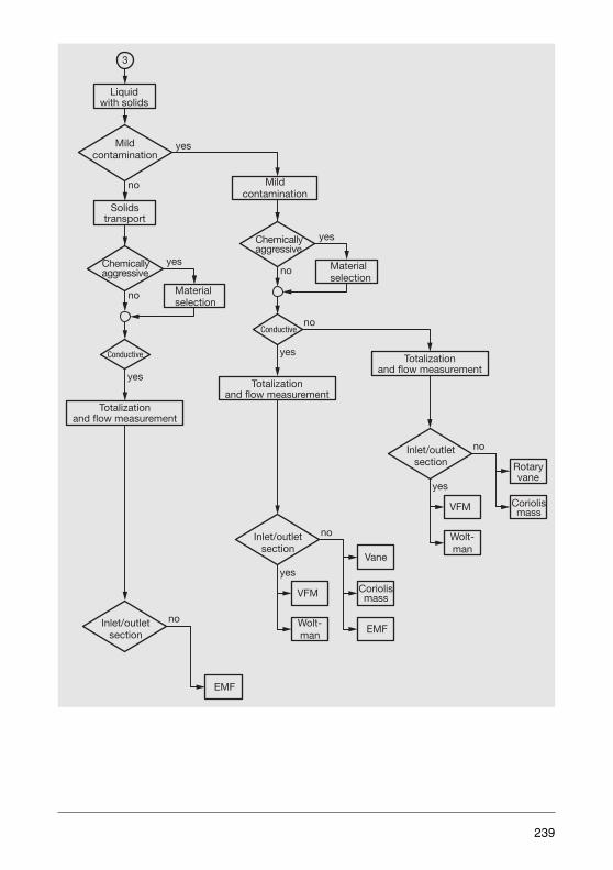
yes
3
no
yes
no
Liquidwith solids
Solidstransport
Mildcontamination
Totalizationand flow measurement
Vane
Wolt-man
Coriolismass
noInlet/outletsection
EMF
no
yes
EMF
VFM
Wolt-man
VFM
no
yes
yesChemicallyaggressive
no Materialselection
Conductive yes
yes
no
Mildcontamination
Chemicallyaggressive
Materialselection
Conductive
Totalizationand flow measurement
Totalizationand flow measurement
Inlet/outletsection
Inlet/outletsection
Coriolismass
Rotaryvane
239
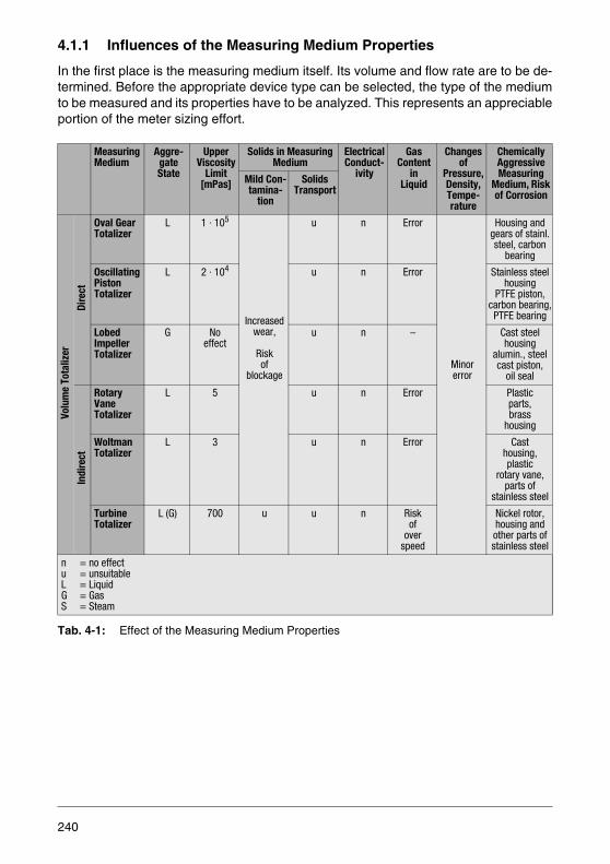
4.1.1 Influences of the Measuring Medium Properties
In the first place is the measuring medium itself. Its volume and flow rate are to be de-termined. Before the appropriate device type can be selected, the type of the mediumto be measured and its properties have to be analyzed. This represents an appreciableportion of the meter sizing effort.
Tab. 4-1: Effect of the Measuring Medium Properties
Measuring Medium
Aggre-gate State
UpperViscosity
Limit[mPas]
Solids in Measuring Medium
ElectricalConduct-
ivity
Gas Content
in Liquid
Changes of
Pressure,Density,Tempe-rature
Chemically Aggressive Measuring
Medium, Risk of Corrosion
Mild Con-tamina-
tion
SolidsTransport
Volu
me
Tota
lizer
Dire
ct
Oval GearTotalizer
L 1 · 105
Increasedwear,
Risk of
blockage
u n Error
Minorerror
Housing and gears of stainl. steel, carbon
bearing
Oscillating PistonTotalizer
L 2 · 104 u n Error Stainless steel housing
PTFE piston,carbon bearing,PTFE bearing
Lobed ImpellerTotalizer
G Noeffect
u n – Cast steelhousing
alumin., steelcast piston,
oil seal
Indi
rect
Rotary VaneTotalizer
L 5 u n Error Plasticparts, brass
housing
WoltmanTotalizer
L 3 u n Error Casthousing,plastic
rotary vane,parts of
stainless steel
TurbineTotalizer
L (G) 700 u u n Riskof
overspeed
Nickel rotor,housing and other parts of stainless steel
n = no effectu = unsuitableL = LiquidG = GasS = Steam
240

Tab. 4-2: Effect of the Measuring Medium Properties
Measuring Medium
AggregateState
UpperViscosity
Limit[mPas]
Solids in Meas. Medium Electr.Con-duct-ivity
Gas Content
inLiquid
Changes of
Pressure,Density,Tempe-rature
Chemically Aggressive Measuring
Medium, Risk of Corrosion
Mild Contami-nation
SolidsTrans-
port
Flow
met
er
VortexFlowmeter
L, G, S 7.5 Essentiallyinsensitive tocontamination
u n Cavitat-ion
effectspossible
Gas mea-surementaffected,
liquidmeasure-
ment unaffected
Stainless steel(Hastelloy)
Swirl Flowmeter
L, G, S 30(indep. of nominal
diameter)
u n Stainless steel(Hastelloy)
Differential PressureMeasurement
L, G, S seeTable2.4
Damage to me-tering edge,plugging ofpressure
tap connector
u n Error Effecton Δp
Stainless steel
VariableAreaFlowmeter
L, G, S 100(700)
Damage to
metering edge
u n Error Densitychangesbuoyancy
Stainless steelHastelloy,
PTFE, glass
Electro-magneticFlowmeter
L Noeffect
n n ≥ 0.5μs/cm
Error n PTFE, PFA, platinum
Ultrasonic Flowmeter
L (G) Re-effect
Only allowed for Doppler,
damping fortransit time
u n Error forDoppler,dampingfor transit
time
Soundvelocity
changes for Doppler
Stainless steel, PTFE
Mass Flowmeter,Coriolis
L (G) Noeffect
Possible withrestrictions
u n Error Density ismeasured variable
Stainl. steel Hastelloy
MassFlowmeter,Thermal
G Noeffect
Essentiallyinsensitive
to con-tamination
u n – n Stainl. steel,Hastelloy,ceramic
n = no effectu = unsuitableL = LiquidG = GasS = Steam
241
Viscosity Effects
Viscosity is a property of the measuring medium. Through use of the Reynolds numberit is possible to coordinate the viscosity effects and the dimensions of the measuringpoint. For Re < 2300 laminar flow exists with a large viscosity effect. The transition re-gion exists between approximately 2300 < Re < 3000 above which turbulence exists.In the turbulent region there are no limitations due to viscosity. Small Re values havevarying effects, depending on the measuring method.
For gas totalization or flow measurement the viscosity effect is hardly noticeable. Onlyfor small variable area flowmeters with light-weight floats does the effect increaseslightly in the lower measuring ranges.
The situation for liquids is quite different. Completely viscosity-independent are theelectromagnetic flowmeters and the mass flowmeters, although the pressure drop inthe latter is affected as a function of the length of the measuring section. Ultrasonicflowmeters have difficulties in the transition region from laminar to turbulent flow.
In Vortex, swirl and turbine flowmeters an increasing viscosity raises the lower rangevalue, thus reducing the span.
Oval gear and oscillating piston meters are ideal devices for high viscosities. At higherviscosity they become more accurate because of the decrease in gap losses.
A special float design helps to minimize the effects of viscosity in flowmeters of thistype.
Solids in the Measuring Medium
The presence of solids in the medium has various effects. First there is the usually un-desirable contamination,then there are mixtures such as pastes and slurries, and finallythere is the hydraulic transport of solids. Contamination is undesirable because itsamount and effects are difficult to predict. Gases can convey liquids or dust particles.Solid particles in a gas are dangerous because the gas flow velocities are high andtherefore the kinetic energy of the particles can be appreciable, so that they may be-come destructive or cause deposits .
The lobed impeller gas totalizer requires that the gases is filtered. In the startup phasea screen with 0.1 to 0.2 mm of mesh is recommended. Additionally, a flushing systemcan be used to remove dirt. In differential pressure and variable area flowmeters dustparticles may damage the highly sensitive metering edges.
Unclean liquids may cause a higher wear of rotary totalizers. In the worst case the ro-tating parts may become stuck. Vortex and swirl flowmeters flush minor contaminationthrough the meter.
242
If a non-conducting coating (oil, grease) in an electromagnetic flowmeter isolates theelectrically coupled electrodes from the liquid, then a meter with capacitively coupledelectrodes must be installed. A conductive coating, e.g. from magnetite, only results inmeasuring error when the medium (in this case water) has a conductivity of less than100 μS/cm. Otherwise, the electromagnetic flowmeters is the least affected meter.
A special case is the ultrasonic flowmeter, because the Doppler principle requires someforeign bodies as reflectors. The transit time principle can only tolerate a minor amountof dirt particles and will not operate if gas bubbles are present. Deposits affect thesound path and cause measuring errors.
A prerequisite for proper functioning of the mass flowmeter is that the solid particles fol-low the vibrations, which again is a function of the fluid viscosity. Therefore, with an in-creasing mass and inertia of the particle the risk of incorrect measurements increases.
Hydraulic Solids Transport
For hydraulic solids transport, e.g. for coal or dredging slurries, a piping system withoutany constrictions or obstructions is required. Increased abrasion is also alwayspresent. The flow measurement in sections of this kind is only possible with electro-magnetic flowmeters. The abrasion effect can be minimized by selecting the appropri-ate materials for the liner (ceramic carbide, PU, soft rubber) and electrodes (Hastelloy).The mass flow rate of the moving solids is generally the variable which is desired forhydraulic solids transport. Therefore a density meter (radioisotope density meter) anda volume flowmeter are combined and the mass flow rate is calculated from the productof the two values.
Deposits
Undesirable deposits in the pipings are removed with scrapers. The effectiveness ofthe scraper requires, among other things, a constant inside diameter along the entirelength of the piping. The flowmeter installed in the piping is of course subjected to thesame requirements, i.e., matching of the inside diameter without steps. Only electro-magnetic and ultrasonic flowmeters can be individually adapted. Multipipe mass flow-meters cannot be scraped at all.
Gas Content in a Liquid
The devices used for the flow measurement of liquids are volume flowmeters that arenot capable of differentiating between a gas and a liquid. For this reason, gaseous com-ponents in a liquid cause errors the magnitude of which is equal to the proportion of gasin the mixture. A correct measurement can be expected to be obtained with a Coriolismass flowmeter. But here also errors occur because of the damping characteristics ofthe gases.
243

Beyond these there are some side effects which must also be considered. For turbineflowmeters it might happen that larger gas bubbles could cause over speeding. Cavi-tation is readily generated at higher flow velocities particularly in Vortex and swirl flow-meters. In the Ultrasonic flowmeters using the transit time principle both the transit timeand the damping are changed so that even small gas bubbles can cause an effect. Er-rors are noted with as little as a 0.2% volume of gas.
Risk of Corrosion due to Aggressive Measuring Media
The effects of corrosion can only be avoided by proper material selection. A slight inat-tention, for example, in selecting the material for a gasket can result in an inoperativemeasuring device.
The complicated elements of volume totalizers are disadvantaged when it comes tomaterial selections. Therefore, these meters are not favored for applications with cor-rosive media. Rotary vane and Woltman meters are preferred for water measurements.
The flowmeters offer a variety material choices. For differential pressure flowmeters itis important to consider that not only the orifice must be corrosion resistant, but alsothe pressure lines and fittings. In certain installations an isolating fluid or gas is injectedinto the pressure line in order to prevent the entry of dangerous fluids.
Variable area flowmeters made of special materials are expensive and, therefore, rare-ly deployed. The same holds true for the mass flowmeters.
Suitable solutions to the problems are offered only by the electromagnetic and ultra-sonic flowmeters. The smooth meter tube can be coated with a corrosion resistant linersuch as PTFE, for example. Ultrasonic probes in ultrasonic flowmeters and electrodesin electromagnetic flowmeters are process-wetted, i.e. they extend through the pipe orliner and are, thus, in direct contact with the measuring medium. The ultrasonic probecan be protected with a stainless steel or Hastelloy coating. There are better alterna-tives available in the electromagnetic flowmeters. A wide variety of electrode materialsare available, ranging from stainless steel over Monel, Titanium, Hastelloy and Plati-num to Carbon.
4.1.2 Flow Regime Effects
The measuring medium flowing through the piping has characteristics which effect theflow regimes, particularly in combination with the pipeline configuration. On the otherhand, the measuring devices only have a limited ability to process these effects withouterrors. In other words, there are limitations which are characterized by the velocity pro-file and the Reynolds number.
244
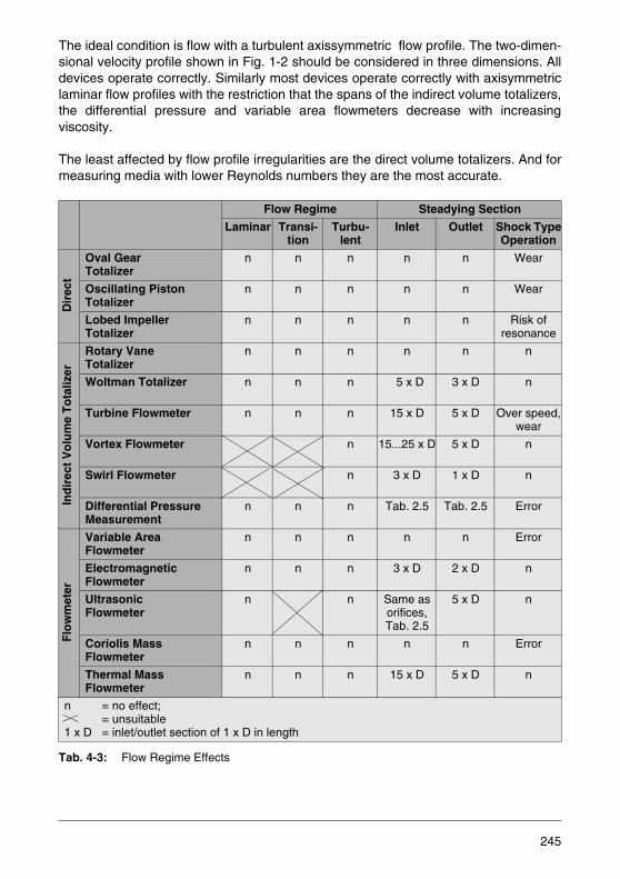
The ideal condition is flow with a turbulent axissymmetric flow profile. The two-dimen-sional velocity profile shown in Fig. 1-2 should be considered in three dimensions. Alldevices operate correctly. Similarly most devices operate correctly with axisymmetriclaminar flow profiles with the restriction that the spans of the indirect volume totalizers,the differential pressure and variable area flowmeters decrease with increasingviscosity.
The least affected by flow profile irregularities are the direct volume totalizers. And formeasuring media with lower Reynolds numbers they are the most accurate.
Tab. 4-3: Flow Regime Effects
Flow Regime Steadying Section
Laminar Transi-tion
Turbu-lent
Inlet Outlet Shock TypeOperation
Dir
ect
Oval Gear Totalizer
n n n n n Wear
Oscillating Piston Totalizer
n n n n n Wear
Lobed Impeller Totalizer
n n n n n Risk of resonance
Ind
irec
t V
olu
me
To
taliz
er
Rotary Vane Totalizer
n n n n n n
Woltman Totalizer n n n 5 x D 3 x D n
Turbine Flowmeter n n n 15 x D 5 x D Over speed,wear
Vortex Flowmeter n 15...25 x D 5 x D n
Swirl Flowmeter n 3 x D 1 x D n
Differential PressureMeasurement
n n n Tab. 2.5 Tab. 2.5 Error
Flo
wm
eter
Variable AreaFlowmeter
n n n n n Error
ElectromagneticFlowmeter
n n n 3 x D 2 x D n
UltrasonicFlowmeter
n n Same as orifices, Tab. 2.5
5 x D n
Coriolis Mass Flowmeter
n n n n n Error
Thermal Mass Flowmeter
n n n 15 x D 5 x D n
n = no effect; = unsuitable
1 x D = inlet/outlet section of 1 x D in length
245
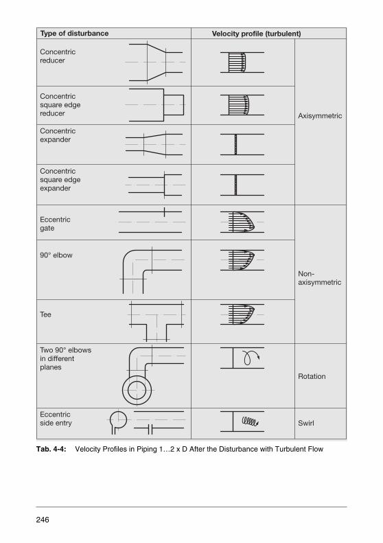
Tab. 4-4: Velocity Profiles in Piping 1…2 x D After the Disturbance with Turbulent Flow
Axisymmetric
Concentricsquare edgereducer
Concentricexpander
Concentricsquare edgeexpander
Eccentricgate
Non-axisymmetric
90° elbow
Tee
Two 90° elbowsin differentplanes
Rotation
Eccentricside entry Swirl
Type of disturbance Velocity profile (turbulent)
Concentricreducer
246
Disturbed flow profiles in turbulent flows must be considered independently of the de-vice type. Tab. 4-4 shows a number of examples of disturbances and their influence onthe velocity profile cross sections. Direct volume totalizers have no difficulty with suchchanges. The same holds true for variable area and Coriolis mass flowmeters as wellas for swirl flowmeters.
The differential pressure flowmeters are very sensitive to disturbances. Long, distur-bance-free straight pipe sections should provide for equilibration (Tab. 2-4). The ultra-sonic flowmeter is affected when its very narrow sound beam does not sense all thevelocity differences, which is very seldom the case. Therefore, requirements similar tothose for the differential pressure flowmeters are valid. The two or more beam ultrason-ic flowmeters are better suited for such conditions.
Axissymmetric flow profiles are good-natured disturbances that lose their effects aftereven short inlet sections. The step changes can, however, carry along wall vortices. In-direct totalizers, electromagnetic flowmeters and mass flowmeters do not encounterany problems.
The situation is quite different with non-symmetric profiles. Direct volume totalizers re-quire an inlet section of 10...15 x D (inlet and outlet sections are straight pipe sectionsthat have the same diameter as the measuring device; flow straighteners provide ameans for shortening the required section length), whereas electromagnetic flowme-ters demand only sections of 3...5 x D. Swirl and transverse vortices persist in straightsections over long distances. Since their effects on the measuring accuracy are appre-ciable, flow straighteners must be used to eliminate their effects.
The inlet sections listed in Tab. 4-3 should be installed upstream of the meters. Addi-tional outlet sections should be provided to prevent feedback from disturbances down-stream of the sensor. Their lengths are between 3 x D and 10 x D.
247
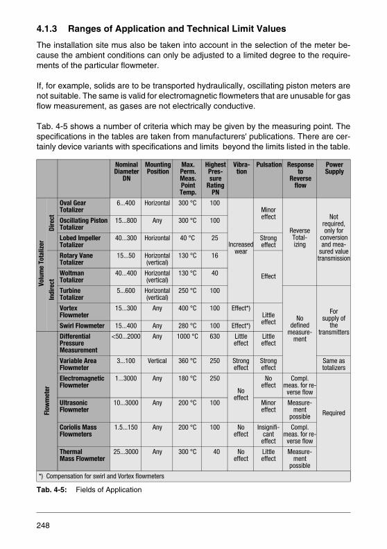
4.1.3 Ranges of Application and Technical Limit Values
The installation site mus also be taken into account in the selection of the meter be-cause the ambient conditions can only be adjusted to a limited degree to the require-ments of the particular flowmeter.
If, for example, solids are to be transported hydraulically, oscillating piston meters arenot suitable. The same is valid for electromagnetic flowmeters that are unusable for gasflow measurement, as gases are not electrically conductive.
Tab. 4-5 shows a number of criteria which may be given by the measuring point. Thespecifications in the tables are taken from manufacturers' publications. There are cer-tainly device variants with specifications and limits beyond the limits listed in the table.
Tab. 4-5: Fields of Application
Nominal Diameter
DN
MountingPosition
Max. Perm.Meas. PointTemp.
HighestPres-sure
RatingPN
Vibra-tion
Pulsation Responseto
Reverse flow
Power Supply
Volu
me
Tota
lizer
Dire
ct
Oval GearTotalizer
6...400 Horizontal 300 °C 100
Increasedwear
Minoreffect
ReverseTotal-izing
Notrequired,only for
conversionand mea-
sured valuetransmission
Oscillating PistonTotalizer
15...800 Any 300 °C 100
Lobed ImpellerTotalizer
40...300 Horizontal 40 °C 25 Strongeffect
Indi
rect
Rotary VaneTotalizer
15...50 Horizontal(vertical)
130 °C 16
EffectWoltmanTotalizer
40...400 Horizontal(vertical)
130 °C 40
TurbineTotalizer
5...600 Horizontal(vertical)
250 °C 100
Nodefined
measure-ment
For supply of
the transmitters
Vortex Flowmeter
15...300 Any 400 °C 100 Effect*)LittleeffectSwirl Flowmeter 15...400 Any 280 °C 100 Effect*)
Flow
met
er
Differential PressureMeasurement
<50...2000 Any 1000 °C 630 Littleeffect
Littleeffect
Variable Area Flowmeter
3...100 Vertical 360 °C 250 Strongeffect
Strongeffect
Same astotalizers
ElectromagneticFlowmeter
1...3000 Any 180 °C 250
Noeffect
Noeffect
Compl. meas. for re-
verse flow
Required
UltrasonicFlowmeter
10...3000 Any 200 °C 100 Minoreffect
Measure-ment
possible
Coriolis Mass Flowmeters
1.5...150 Any 200 °C 100 Noeffect
Insignifi-cant
effect
Compl. meas. for re-
verse flow
ThermalMass Flowmeter
25...3000 Any 300 °C 40 Noeffect
Littleeffect
Measure-ment
possible
*) Compensation for swirl and Vortex flowmeters
248

Pressure and Temperature
Housing strength due to its wall thickness and material selection, mechanical toleranc-es for temperature expansion, gasket type and material, sensors limits and the effectson the transmitting element; these are some of the considerations that have an effecton the device selection for high temperatures and pressures. For variable area flowme-ters a distinction is made between devices with glass tube and those with a metal tube.The pressure and temperature limitations for glass tube meters naturally lie far belowthose for metal tube meters.
Differential pressure flowmeter selection includes the fittings, pressure lines and trans-mitters. These parts must be designed appropriately. The limiting values for the trans-mitter are decisive for the entire system. As the maximum temperature limit for trans-mitters is usually around 120 °C, higher temperatures must be reduced accordingly byisolators in the pressure line.
Vibration
Piping vibrations primarily cause wear on the moving parts and bearings in volume to-talizers. In the oscillating elements in Vortex and mass flowmeters, the vibration fre-quencies are superimposed on the measurement frequencies, thus causing errors. Ifresonance occurs, parts may fracture. The ABB Vortex flowmeter is substantially in-sensitive to vibrations because of the separation of the sensor from thebluff body and the oscillation compensation in the sensor.
Because of its S-shape double tube design the CoriolisMaster mass flowmeter mea-sures differential signals which are essentially decoupled from external vibrations. Ad-ditionally, the digital filter technology assures wide insensitivity to external vibrations.Should the vibrations be the same as the excitation frequency, then the measurementscould be affected.
The relatively large mass of its float makes the device sensitive to vibrations. Therefore,snubbers should be used and the devices should be fixed to the wall.
Pulsation
Pulsation effects are a function of the inertia of the measuring system. Only when themeasuring element can follow the pulsations without lag will the measurement be un-affected.
Measuring devices with moving parts are, thus, subjected to increased wear. There-fore, it is essential to use the appropriate snubbers. Oval gear and oscillating pistonmeters have so much inertia that that they provide a degree of self damping sufficientfor averaging purposes. The measuring error will slightly increase.
249

In Chapter 2.1.3 the dangerous effect of pulsation on lobed impeller totalizers has al-ready been described. Turbine, vortex and swirl flowmeters measure the flow essen-tially without inertia, but they include time constant elements in the connected transmit-ters. Again the average is obtained with slightly larger errors. Gas turbine flowmetersare in danger when the rotational speed increases too quickly resulting in more bearingwear if over speeding occurs.
As a result of the nonlinear relationship between the flow rate and the differential pres-sure, the error in differential pressure flowmeters caused by pulsation also changesnonlinearly. Therefore, a damping device is definitely recommended, preferably usingstorage volumes or expansion tanks in the measuring medium line. The Hodgson num-ber can be used to calculate the required volumes. The damping elements in differen-tial pressure transmitters compensate for small pulsations.
The float of a variable area flowmeter tends to dance when pulsations are present.Therefore, damping elements must also be used here. Metal cone variable area flow-meters can be equipped with the appropriate damping elements.
Reverse Flow Measurement
An extreme form of pulsation can lead to reverse flow. On the other hand, many pipingsare specifically designed and used for bidirectional flow. Are there flowmeters whichcan also measure reverse flow?
Direct volume totalizers can naturally reverse their direction and totalize backwardswhen their secondary sides include appropriate provisions. The best solutions are pro-vided by the electromagnetic and mass flowmeters which provide all measurementsfor both flow directions and can switch automatically.
Power Supply
Measurement and control technology operates with measurement signals which mustbe transmitted over long distances. Therefore, all totalizers and flowmeters provide ap-propriate output signals the generation of which requires electrical power. The flowme-ters additionally require power supply for their operation.
When only local indication is needed, totalizers and variable area flowmeters do not re-quire electrical supply cables.
In very few cases 0.2 to 1 bar pneumatic standard signals are used. For this purposethe measuring devices must be equipped with the corresponding transmitters the pow-er of which is provided by a compressed air supply of 1.4 bar. Pneumatic transmittersare found in differential pressure and variable area flowmeters.
250

Grounding the Electromagnetic Flowmeters
Grounding per VDE 0100 is not only required because of safety considerations but alsoto assure proper operation of the flowmeter sensor. The signals measured at the elec-trodes are only a few millivolts in amplitude and can be affected by stray groundcurrents which may flow through the flowmeter or measuring path and may exceed atolerable degree. To comply with VDE 0100, Part 540, the sensors' grounding screwsmust be connected to functional ground (for explosion-proof designs per VDE 0165 toa potential equalization bonding conductor). For measurement reasons the ground po-tential and the signal potential of the measuring medium should be identical, if possible.No additional grounding via the terminals (power supply) is required. Plastic pipes orpipes with insulated liner are grounded by using a grounding plate or grounding elec-trodes. If the piping section is not free of stray currents, it is recommended that agrounding plate be installed on each side, i.e. upstream and downstream of the flow-meter.
Grounding electrodes are used when price considerations are decisive and no straycurrents are present. It should be noted that not all device variants can be specified withgrounding electrodes.
One grounding plate is installed when plastic or insulated pipings are used and for de-vice designs, which are not available with grounding electrodes.
Two grounding plates are installed for insulated pipings when stray potentials may existin the piping. This is also true when cathodic protection is used and the flowmeter sen-sor is to be installed electrically insulated in the piping so that the cathodic potential canbe shunted around the sensor.
251
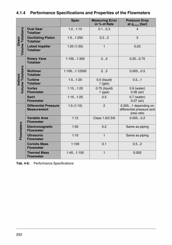
4.1.4 Performance Specifications and Properties of the Flowmeters
Tab. 4-6: Performance Specifications
Span Measuring Error in % of Rate
Pressure Dropat qvmax [bar]
Dir
ect
Vo
lum
e T
ota
lizer
s Oval Gear Totalizer
1:2...1:10 0.1...0.3 4
Oscillating Piston Totalizer
1:5...1:250 0.2...2 3
Lobed Impeller Totalizer
1:20 (1:50) 1 0,03
Ind
irec
tV
olu
me
To
taliz
ers
Rotary Vane Totalizer
1:100...1:350 2...3 0.25...0.75
Woltman Totalizer
1:100...1:12500 2...3 0.005...0.5
Turbine Totalizer
1:5...1:20 0.5 (liquid)1 (gas)
0.5...1
Vortex Flowmeter
1:15...1:20 0.75 (liquid)1 (gas)
0.9 (water)0.06 (air)
Swirl Flowmeter
1:15...1:25 0.5 0.7 (water)0.07 (air)
Flo
wm
eter
s
Differential PressureMeasurement
1:5 (1:10) 2 0.005...1 depending on differential pressure and
area ratio
Variable AreaFlowmeter
1:12 Class 1.6/2.5/6 0.005...0.2
ElectromagneticFlowmeter
1:50 0.2 Same as piping
UltrasonicFlowmeter
1:10 1 Same as piping
Coriolis Mass Flowmeter
1:100 0.1 0.5...2
Thermal Mass Flowmeter
1:40...1:150 1 0.002
252
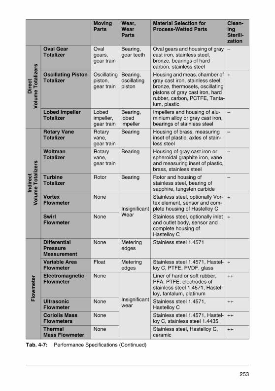
Tab. 4-7: Performance Specifications (Continued)
MovingParts
Wear,Wear Parts
Material Selection for Process-Wetted Parts
Clean-ingSterili-zation
Dir
ect
Vo
lum
e T
ota
lizer
s
Oval Gear Totalizer
Oval gears,gear train
Bearing,gear teeth
Oval gears and housing of gray cast iron, stainless steel, bronze, bearings of hard carbon, stainless steel
–
Oscillating Piston Totalizer
Oscillating piston,gear train
Bearing,oscillating piston
Housing and meas. chamber of gray cast iron, stainless steel, bronze, thermosets, oscillating pistons of gray cast iron, hard rubber, carbon, PCTFE, Tanta-lum, plastic
+
Lobed Impeller Totalizer
Lobed impeller,gear train
Bearing,lobed impeller
Impellers and housing of alu-minium alloy or gray cast iron, bearings of stainless steel
–
Ind
irec
tV
olu
me
To
taliz
ers
Rotary Vane Totalizer
Rotary vane,gear train
Bearing Housing of brass, measuring inset of plastic, axles of stain-less steel
–
Woltman Totalizer
Rotary vane,gear train
Bearing Housing of gray cast iron or spheroidal graphite iron, vane and measuring inset of plastic, brass, stainless steel
–
Turbine Totalizer
Rotor Bearing Rotor and housing ofstainless steel, bearing of sapphire, tungsten carbide
–
Vortex Flowmeter
None
InsignificantWear
Stainless steel, optionally Vor-tex element, sensor and com-plete housing of Hastelloy C
+
SwirlFlowmeter
None Stainless steel, optionally inlet and outlet body, sensor and complete housing of Hastelloy C
+
Flo
wm
eter
Differential PressureMeasurement
None Meteringedges
Stainless steel 1.4571
Variable AreaFlowmeter
Float Meteringedges
Stainless steel 1.4571, Hastel-loy C, PTFE, PVDF, glass
+
ElectromagneticFlowmeter
None
Insignificantwear
Liner of hard or soft rubber, PFA, PTFE, electrodes of stainless steel 1.4571, Hastel-loy, tantalum, platinum
++
UltrasonicFlowmeter
None Stainless steel 1.4571, Hastelloy C
++
Coriolis Mass Flowmeters
None Stainless steel 1.4571, Hastel-loy C, stainless steel 1.4435
++
Thermal Mass Flowmeter
None Stainless steel, Hastelloy C, ceramic
++
253
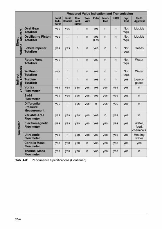
Tab. 4-8: Performance Specifications (Continued)
Measured Value Indication and TransmissionLocalIndi-cator
Limit Contact
Cur-rent
Output
Two-Wire
Pulse Inter-face
HART Expl. Prot
Certif.Approval
Dir
ect
Vo
lum
e T
ota
lizer
s Oval Gear Totalizer
yes yes n n yes n n Notrequ.
Liquids
Oscillating Piston Totalizer
yes n n n yes(Ex)
n n Notrequ.
Liquids
Lobed Impeller Totalizer
yes yes n n yes n n Notrequ.
Gases
Ind
irec
tV
olu
me
To
taliz
ers
Rotary Vane Totalizer
yes n n n yes n n Notrequ.
Water
Woltman Totalizer
yes n n n yes n n Notrequ.
Water
Turbine Totalizer
n n n n yes n n yes Liquids,gases
Vortex Flowmeter
yes yes yes yes yes yes yes yes n
Swirl Flowmeter
yes yes yes yes yes yes yes yes n
Flo
wm
eter
Differential PressureMeasurement
yes n yes yes n yes yes yes n
Variable AreaFlowmeter
yes yes yes yes yes n yes yes n
ElectromagneticFlowmeter
yes yes yes yes yes yes yes yes Water,food,
chemicals
UltrasonicFlowmeter
yes n yes yes yes yes yes yes Heatingwater
Coriolis Mass Flowmeter
yes yes yes n yes yes yes yes yes
Thermal Mass Flowmeter
yes yes yes n yes yes yes yes n
254
Span
The spans for oval gear and oscillating piston meters are a function of the viscosity ofthe measuring medium. They are 1 : 10 for viscosities up to approx. 300 mPas and in-crease to 1:20 for viscosities of 1 · 104 mPas. The conditions are exactly the oppositefor indirect totalizers and flowmeters. With increasing viscosity the linear lower rangevalue increases and reduces the span.
Because of the square root relationship which exists in the differential pressure mea-surement between the measured variable, the differential pressure and the flow rate,the span depends on the required measuring accuracy. A span of 1:3 promises a veryhigh measuring accuracy.
Electromagnetic and ultrasonic flowmeters represent a special situation in that their up-per range values can be set and, thus, optimized. Thermal mass flowmeters (gas mea-surement) achieve spans up to 1:150.
Error Limits
The error limits represent controversial specifications, because they are values pub-lished by the manufacturers for ideal boundary conditions. In practice deviations fromthe ideal conditions are common, so that additional stipulations must be made for theinstrument accuracies. It is important to realize that the accuracy may be based on thecurrently measured value (% of rate) or on the upper range value (% of max.). In theVDI/VDE Directive 2600 (4) the types of errors, reference values, and error conditionsare defined.Through special calibrations better accuracies can be achieved, which aregenerally valid only for a specific time period. Generally speaking, the error limits canbe affected by contamination, wear and physical changes.
The values listed in the table are based on the currently measured values [% of rate].Anexception is made for the specifications regarding the variable area flowmeters, sincein VDI/VDE 3513 Sheet 2 a classification class system is defined which is based on acombination or errors related to either the rate or the upper range value. 75% of the ofthe error values for an accuracy class are percent of rate values and the other 25% arepercent of max. values.
The sum of the two values yields the accuracy class: 1 - 2.6 - 2.5 - 4 - 6 - 10.
The accuracy is defined by two parameters, G and qG: Error limit G: Constantly per-missible error in % of rate that is valid above the linearity limit qG. Linearity limit qG:Flow limit in % of the max. value, above which the permissible relative error is constant.Below the linearity limit the permissible measuring error increases with decreasingmeasured value in inverse ratio.
255
Wear
Understandably, long-term reliability of the measurement is one of the major user re-quirements. Therefore, the mechanical wear must be kept to a minimum.
Wear is caused primarily by abrasion of the metering elements (through the measuringmedium) and by the bearing friction of the moving parts. Electromagnetic flowmeter canbe considered to be ideal because the smooth inside wall only shows wear when highlyabrasive media are measured such as lime slurries, sand-water mixtures, or coal-watermixtures in hydraulic solids transport. If the walls are lined with polyurethane or soft rub-ber then even these measuring media rarely cause difficulties.
Even though Vortex and swirl flowmeters have no moving parts, they do have partswhich extend into the measuring section. A specific size, hardness and edge sharp-ness of solid particles in the measuring medium must not be exceeded. A low dust con-tent in gases or plastic suspensions, however, is permissible.
In orifice metering the metering edge must remain sharp because, otherwise, even mi-nor changes may cause measuring errors. In extreme cases a nozzle can be used forlow concentrations of solid particles in the measuring medium. Even then the pressureconnections can create problems because they may become plugged. The meteringedge of a variable area flowmeter float is also precisely machined and must not bedamaged.
Bearing wear in totalizers with rotating meter bodies can be added to the difficultiesmentioned above. Even a very small quantity of solid particles in the measuring medi-um may considerably damage these devices. Ideally, the measured medium shouldfeature a certain tendency to lubricate.
256
Materials
Material selection always requires information about corrosion problems. Some mea-suring media are chemically harmless, but can become corrosive when small amountsof othermaterials are present, perhaps only contamination. Therefore care must be exercised.The variety of possible materials is especially restricted where complicated and difficultto manufacture parts are required. This is particularly true for volume totalizers and, toa certain extent, for swirl, vortex and mass flowmeters.
At first glance, differential pressure measurement would seem to present no problems.But not only the orifice plate or the nozzle must be manufactured of resistant materials.It is also important that the pressure line, fittings and transmitters are made of a mate-rial that is suitable for the measuring medium. Sometimes constant flushing of the pres-sure lines is used to help.
The price issue comes up for variable area flowmeters made of stainless steel. Theyare only installed if no supply power is available at the measuring point. The materialselection problem is solved almost ideally for electromagnetic flowmeters because thePTFE liner material can be used for almost all measuring media. Platinum is exception-ally good as an electrode material. It may also be possible to solve the electrode ma-terial problem by using the capacitive electrode design.
The ultrasonic flowmeter requires the proper protective tube material for the soundtransducer (transmitter/receiver).
Cleaning, Sterilization
Why must a closed piping be cleaned? There are various answers: deposits due to sed-imentation or adhesion reduce the cross sections, crystal formations block the flow,residue can contaminate the product. The ability to clean is a determining factor forflowmeter selection.
Where deposits are to be expected meters with moving parts are seldom installed. Dif-ficulties can also be encountered in installations of swirl, Vortex and thermal mass flow-meters. In the ultrasonic flowmeters the sound path is altered so that erroneous mea-surements may occur. In the Coriolis mass flowmeters deposits may cause a zeroshift. Nonconducting deposits affect the electromagnetic flowmeters unless the samemeter type with capacitive electrodes is installed. Electrically conductive deposits shortout the measuring signal and cause erroneous measurements.
257

Deposits are removed by flushing, dissolving, or by mechanical cleaning using a brushor scraper. An unobstructed cross-section is a big advantage for this method. Using ascraper even requires a piping with a defined diameter without internal steps. This re-quirement can only be met by the electromagnetic flowmeter, and perhaps by the ultra-sonic flowmeter. Residues remaining in the piping are a special problem in the food andbeverages industries, where bacteria may contaminate the final product. Thoroughcleaning and sterilization using steam, liquid cleaning agents, acids and bases aremandatory. This is usually accomplished using CIP (Cleaning In Place) and SIP (Ster-ilisation in Place) procedures, in which all elements in the system remain in place. TheCIP capability is determined by testing and confirmed by certificates. The oscillatingpiston meter must be disassembled for cleaning.
4.1.5 Installation and Maintenance
The user of measurement information expects a problem free installation of the meterand thereafter only wants to see accurate measurement values, the meter itself is nolonger of interest. Even though modern technology comes close to fulfilling these ex-pectations, regular monitoring can prevent failures. Therefore included in the selectionof a meter is the question regarding the capabilities of the maintenance personnel.
The flowmeter, e.g. a Vortex or thermal mass flowmeter, is installed in the piping in arelatively straightforward manner using flanged or threaded connections while givingconsideration to the inlet and outlet sections. At this point the requirement for stressfree installation must be emphasized because very often the meters are installed inexisting pipings, and existing stress is transferred to the meters. Wafer-type designrequires exact centering. And there are ultrasonic flowmeters the measuring elements(transmitter/receiver) of which are welded into the piping wall. This method produceserror free measurements only when an on-site calibration is conducted which takes intoaccount the actual piping geometry.
The work is essentially completed when totalizers and variable area flowmeters whichoperate without an external power supply are installed . Flowmeter sensors and sepa-rate transmitters communicate with each other with low-level signals that are sensititveto interference. For this reason special shielded cables are used. Flowmeters with in-tegral mount design do not require this effort.
258
An appreciable expense is required for differential pressure flowmeter installations. Inthis case, the pressure lines and various fittings must be installed and connected. Also,differential pressure transmitters require an external power supply.
All measuring devices are designed such that maintenance personnel can monitor theirproper functional operation using a simple tests. The majority of these devices are self-monitoring and report errors.
The wear in bearings and measuring elements of rotating totalizers can usually be bestdetermined by a visual examination. That is why these totalizers are designed such thatthey can be opened on site.
When installing electromagnetic flowmeters, it must be ensured that they are axissym-metrically fitted, that they are filled with the medium to be measured and that they arenot operated when empty. An exception is the FXP4000 flowmeter. This electromag-netic flowmeter is suitable for use in partially filled pipings. If it cannot be avoided thata system is sometimes run empty, the signal outputs are switched off accordingly, ei-ther via an external contact, for pipe sizes greater than DN 10 and cable lengths of upto 50 m (remote mount design), or automatically by means of an empty pipe detectorfunction. This avoids measuring errors in the measuring section when the pipe is emp-ty.
For the majority of installations it is fully sufficient to realize a straight inlet section of3 x D of the nominal diameter and an outlet section of 2 x D of the nominal diameter ofthe flowmeter sensor. These are the manufacturers' specifications. According to thereference conditions stipulated in EN 29104, for systems to be approved by theWeights and Measures Office, and to comply with the DVGW Directives other straightsection lengths are specified and must be observed.
Valves or other shut-off elements should be installed in the outlet section. A slight slopeof approx. 3 % is advantageous for degassing. It should be ensured that the imaginaryline which connects the two electrodes is horizontal if possible or no more than 45° fromthe horizontal, so that any air or gas bubbles cannot affect the measurement voltage.
259
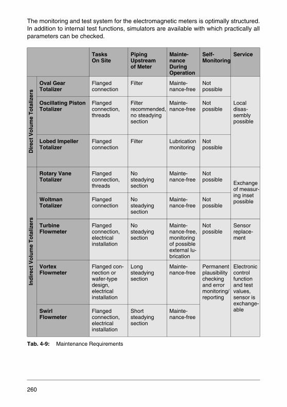
The monitoring and test system for the electromagnetic meters is optimally structured.In addition to internal test functions, simulators are available with which practically allparameters can be checked.
Tab. 4-9: Maintenance Requirements
TasksOn Site
Piping Upstream of Meter
Mainte-nance During Operation
Self-Monitoring
Service
Dir
ect
Vo
lum
e T
ota
lizer
s
Oval Gear Totalizer
Flangedconnection
Filter Mainte-nance-free
Not possible
Localdisas-semblypossible
Oscillating Piston Totalizer
Flangedconnection,threads
Filter recommended, no steadying section
Mainte-nance-free
Not possible
Lobed Impeller Totalizer
Flangedconnection
Filter Lubrication monitoring
Not possible
Ind
irec
t V
olu
me
To
taliz
ers
Rotary Vane Totalizer
Flangedconnection,threads
Nosteadyingsection
Mainte-nance-free
Not possible
Exchange of measur-ing insetpossibleWoltman
Totalizer Flangedconnection
Nosteadyingsection
Mainte-nance-free
Not possible
Turbine Flowmeter
Flangedconnection,electricalinstallation
Nosteadyingsection
Mainte-nance-free, monitoring of possible external lu-brication
Not possible
Sensorreplace-ment
Vortex Flowmeter
Flanged con-nection orwafer-typedesign,electricalinstallation
Longsteadyingsection
Mainte-nance-free
Permanentplausibility checkingand errormonitoring/reporting
Electroniccontrolfunction and testvalues,sensor isexchange-ableSwirl
FlowmeterFlangedconnection,electricalinstallation
Shortsteadyingsection
Mainte-nance-free
260

Tab. 4-10: Maintenance Efforts, Continued
TasksOn Site
Piping Upstream of Meter
Mainte-nance During Operation
Self-Monitoring
ServiceF
low
met
er
Differential PressureMeasurement
Center meter in flange, pres-sure line, fit-tings, transmit-ter, power supply
Long inlet and outlet sections
Regularinspection required
Not possible
Direct measure-mentat transmitter
Variable AreaFlowmeter
Flangedorthreaded connection
No regulations Mainte-nance-free
Permanentplausibilitychecking,error moni-toring andreporting
Glass flow-meterwith “SNAP-IN” design
ElectromagneticFlowmeter
Flangedconnection,electricalinstallation
Short inlet and outlet sections
Mainte-nance-free
El. control function and test values, simulators
UltrasonicFlowmeter
Flangedconnection,or weld-in socket, el. installation
Long inlet and outlet sections
Mainte-nance-free
Signalling few failures
Coriolis Mass Flowmeter
Flangedconnection,wall-mount-ing, electrical installation
No regulations Mainte-nance-free
Permanentplausibilitychecking,error moni-toring andreporting
Electronic control functions and test values
Thermal Mass Flowmeter
Flanged, wafer-type mounting and plug-in sensors
Inlet/outlet sections
Mainte-nance-free
Errorreporting
Measuringsensorcan be exchanged
261
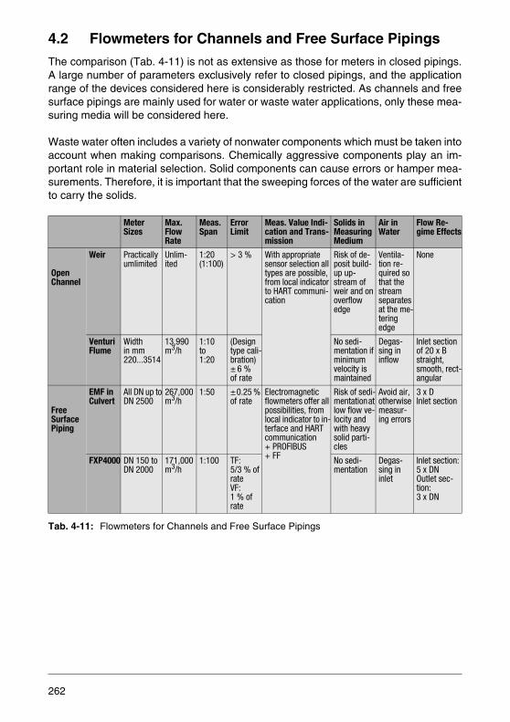
4.2 Flowmeters for Channels and Free Surface Pipings
The comparison (Tab. 4-11) is not as extensive as those for meters in closed pipings.A large number of parameters exclusively refer to closed pipings, and the applicationrange of the devices considered here is considerably restricted. As channels and freesurface pipings are mainly used for water or waste water applications, only these mea-suring media will be considered here.
Waste water often includes a variety of nonwater components which must be taken intoaccount when making comparisons. Chemically aggressive components play an im-portant role in material selection. Solid components can cause errors or hamper mea-surements. Therefore, it is important that the sweeping forces of the water are sufficientto carry the solids.
Tab. 4-11: Flowmeters for Channels and Free Surface Pipings
MeterSizes
Max.FlowRate
Meas. Span
Error Limit
Meas. Value Indi-cation and Trans-mission
Solids in Measuring Medium
Air in Water
Flow Re-gime Effects
OpenChannel
Weir Practicallyumlimited
Unlim-ited
1:20(1:100)
> 3 % With appropriate sensor selection all types are possible, from local indicator to HART communi-cation
Risk of de-posit build-up up-stream of weir and on overflow edge
Ventila-tion re-quired so that the stream separates at the me-tering edge
None
Venturi Flume
Widthin mm220...3514
13,990 m3/h
1:10to1:20
(Design type cali-bration)± 6 %of rate
No sedi-mentation if minimum velocity is maintained
Degas-sing in inflow
Inlet section of 20 x B straight, smooth, rect-angular
FreeSurfacePiping
EMF in Culvert
All DN up toDN 2500
267,000m3/h
1:50 ±0.25 % of rate
Electromagnetic flowmeters offer all possibilities, from local indicator to in-terface and HARTcommunication+ PROFIBUS+ FF
Risk of sedi-mentation at low flow ve-locity and with heavy solid parti-cles
Avoid air, otherwise measur-ing errors
3 x DInlet section
FXP4000 DN 150 toDN 2000
171,000m3/h
1:100 TF:5/3 % of rateVF:1 % of rate
No sedi-mentation
Degas-sing in inlet
Inlet section: 5 x DNOutlet sec-tion:3 x DN
262
4.2.1 Solids in the Measuring Medium
When the flow velocity in the dammed area ahead of a weir decreases the solid parti-cles carried along with the fluid will settle. The deposits change the geometric condi-tions and cause measuring errors. Floating particles change the geometry even moreand may plug the meter overflow.
The Venturi flume accelerates the fluid in its constricted areas and drives the solidsthrough. The floating particles may have a negative impact on the level measurement.Foam build up causes measurement errors which are a function of the type of sensorused.
In pipe culverts extremely low velocities can be present, leading to the formation of de-posits which, however, have little or no effect on the measurements. When the velocityincreases, the culvert is flushed (sand deposits in straight pipes are already carriedalong at velocities > 0.25 m/s).
4.2.2 Gas Content
The gas content is usually due to entrained air. Since all the devices discussed in thischapter measure the volume flow, the air content in the water is considered as fluid andcauses an error as large as the volume of the entrained air.
The weir requires ventilation through air entry at its sides so that the overflow streamcan separate from the metering edge and does not attach to the outer side of the weirdue to the presence of a vacuum. Air resulting from this ventilation causes no errorsbecause the level measurement is made approx. 4 x h upstream of the weir. Basicallyopen channel measurements are rarely affected by entrained air.
The FXP4000 also allows the measuring medium to deaerate within the inlet section.It is, however, possible that in fully filled pipings air remains in the water and cannotescape before reaching the measuring section. This may result in measuring errors.
In culverts air can be sucked in due to vortices in the inlet. This effect can be avoidedby increasing the air level upstream of the culvert (inlet shaft). When the incoming fluidfalls into the inlet shaft as a free stream the same air injection effects occur.
263

4.2.3 Flow Regime Effects
The flow regime effects in closed pipings have already been discussed in Chapter4.1.2. What is said there also applies in this situation, especially for electromagneticflowmeters in culverts. An additional parameter complicates the measurements in openchannels and that is the nature of the upper surface of the liquid because wave motionas the sensor seat will be included in the measurements. The weir is not as affected asthe Venturi flume.
The Venturi flume dams the flow in the water inlet section and thereby quiets the sur-face when subcritical flow is present. The inlet section should be straight with a con-stant cross sectional area without any unevenness.. The location of any hydraulic jumpshould be at least 20 x w (flume width) upstream of the Venturi flume. On the outlet sidethere is a requirement that in no case may backflow be present in the Venturi flumewhich could produce a level at the measuring point that corresponds to a higher flowrate. The Parshall flume allows for a slight backflow.
This backflow can be ideally handled in the FXP4000 electromagnetic flowmeter forpartially full pipings because this meter measures the combined dynamic effects of ve-locity and the utilized cross sectional area. This means that at zero flow no meteringsignal exists. The FXP4000 can measure flow in both directions. This means, it canalso measure the backflow.
The velocity distribution within the flow cross sectional area in the FXP4000 should beapproximately uniform. Therefore subcritical flow is preferred so that the irregularitiesthat might exist in the vicinity of a hydraulic jump can be avoided. Below are shownsome practical piping installations:
Fig. 4-1: Pipe Inlet
>10xD
>5xD
264
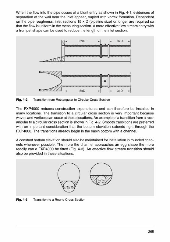
When the flow into the pipe occurs at a blunt entry as shown in Fig. 4-1, evidences ofseparation at the wall near the inlet appear, oupled with vortex formation. Dependenton the pipe roughness, inlet sections 15 x D (pipeline size) or longer are required sothat the flow is uniform in the measuring section. A more effective flow stream entry witha trumpet shape can be used to reduce the length of the inlet section.
Fig. 4-2: Transition from Rectangular to Circular Cross Section
The FXP4000 reduces construction expenditures and can therefore be installed inmany locations. The transition to a circular cross section is very important becausewaves and vortices can occur at these locations. An example of a transition from a rect-angular to a circular cross section is shown in Fig. 4-2. Smooth transitions are preferredwith an important consideration that the bottom elevation extends right through theFXP4000. The transitions already begin in the basin bottom with a channel.
A constant bottom elevation should also be maintained for installation in rounded chan-nels whenever possible. The more the channel approaches an egg shape the morereadily can a FXP4000 be fitted (Fig. 4-3). An effective flow stream transition shouldalso be provided in these situations.
Fig. 4-3: Transition to a Round Cross Section
5xD 3xD
5xD 3xD
265
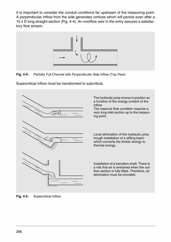
It is important to consider the conduit conditions far upstream of the measuring point.A perpendicular inflow from the side generates vortices which will persist even after a15 x D long straight section (Fig. 4-4). An overflow weir in the entry assures a satisfac-tory flow stream.
Fig. 4-4: Partially Full Channel with Perpendicular Side Inflow (Top View)
Supercritical inflow must be transformed to subcritical.
Fig. 4-5: Supercritical Inflow
The hydraulic jump moves in position as a function of the energy content of the inflow. The insecure flow condition requires a very long inlet section up to the measur-ing point.
Local elimination of the hydraulic jump trough installation of a stilling basin which converts the kinetic energy to thermal energy.
Installation of a transition shaft. There is a risk that air is entrained when the out-flow section is fully filled. Therefore, air elimination must be provided.
266

Fig. 4-6: Flat Gate in Outlet Section
The gate in the piping (Fig. 4-6) generates unsteady flow stream conditions. The hy-draulic influences upstream however are small. Therefore the measuring point shouldbe situated 1 to 3 x D ahead of the gate.
The upstream effects of disturbances downstream of the FXP4000 are relatively smallso that generally a short outlet section is sufficient. An example is the free fall exit(Fig. 4-7).
Fig. 4-7: Free Fall Downstream of the Measuring Point
The measuring point must far enough away so that the water surface level drop offcurve does not begin inside the meter. Usually, a distance of 3 x D is sufficient.
Occasionally, a measurement must be made after a channel bend which may includea sloped bottom (Fig. 4-8). The centrifugal forces produce a sloped surface with aperpendicular secondary flow. The local conditions determine possible measurementerrors.
Fig. 4-8: Cross Section Through a Channel Bend
267

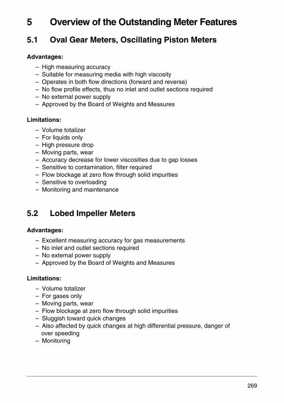
5 Overview of the Outstanding Meter Features
5.1 Oval Gear Meters, Oscillating Piston Meters
Advantages:
– High measuring accuracy – Suitable for measuring media with high viscosity – Operates in both flow directions (forward and reverse) – No flow profile effects, thus no inlet and outlet sections required – No external power supply – Approved by the Board of Weights and Measures
Limitations:
– Volume totalizer – For liquids only– High pressure drop – Moving parts, wear – Accuracy decrease for lower viscosities due to gap losses– Sensitive to contamination, filter required – Flow blockage at zero flow through solid impurities– Sensitive to overloading– Monitoring and maintenance
5.2 Lobed Impeller Meters
Advantages:
– Excellent measuring accuracy for gas measurements – No inlet and outlet sections required – No external power supply – Approved by the Board of Weights and Measures
Limitations:
– Volume totalizer – For gases only– Moving parts, wear – Flow blockage at zero flow through solid impurities – Sluggish toward quick changes– Also affected by quick changes at high differential pressure, danger of
over speeding– Monitoring
269
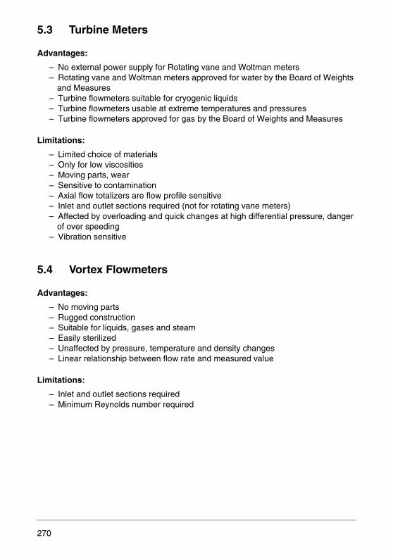
5.3 Turbine Meters
Advantages:
– No external power supply for Rotating vane and Woltman meters – Rotating vane and Woltman meters approved for water by the Board of Weights
and Measures – Turbine flowmeters suitable for cryogenic liquids– Turbine flowmeters usable at extreme temperatures and pressures– Turbine flowmeters approved for gas by the Board of Weights and Measures
Limitations:
– Limited choice of materials– Only for low viscosities – Moving parts, wear – Sensitive to contamination– Axial flow totalizers are flow profile sensitive– Inlet and outlet sections required (not for rotating vane meters) – Affected by overloading and quick changes at high differential pressure, danger
of over speeding– Vibration sensitive
5.4 Vortex Flowmeters
Advantages:
– No moving parts– Rugged construction – Suitable for liquids, gases and steam– Easily sterilized– Unaffected by pressure, temperature and density changes– Linear relationship between flow rate and measured value
Limitations:
– Inlet and outlet sections required– Minimum Reynolds number required
270
5.5 Swirl Flowmeters
Advantages:
– No moving parts – Short inlet and outlet sections → 3 x D/1 x D– Suitable for liquids, gases and steam– Excellent repeatability– Unaffected by pressure, temperature and density changes
Limitations:
– Pressure drop– Minimum Reynolds number required
5.6 Differential Pressure Flowmeters
Advantages:
– Universally suitable for liquids, gases and steam– Also usable in extreme situations, e.g. viscosity, due to variety of versions – Calculations possible for unusual situations– Suitable for extreme temperatures and pressures– Range changes possible– Low pressure drop for nozzles
Limitations:
– Square root relationship between flow rate and differential pressure, therefore smaller span
– Affected by pressure and density changes– Pressure drop for orifice plates– Edge sharpness for orifice plates must be assured, therefore no solids or
contamination– Very long inlet and outlet sections – Expensive installation requiring differential pressure lines, fittings and sensors– Installation and maintenance experience advantageous– High maintenance requirements
271
5.7 Variable Area Flowmeters
Advantages:
– Inexpensive– No external power supply required for local indication – Suitable for liquids, gases and steam– No inlet and outlet sections required – Simple meter design, therefore easy to install and maintain– Indication also with opaque liquids – Metal cone meter with transmitter– Metal cone meter can be sterilized, CIP tested
Limitations:
– Vertical mounting position– Constant pressure drop – Affected by density, temperature and viscosity changes– Solids damage metering edge, otherwise slight contamination allowed– Affected by pulsation and vibration– Expensive when exotic materials are required
5.8 Electromagnetic Flowmeters
Advantages:
– Unobstructed flow passage without projecting parts– No moving parts – No additional pressure drop – Essentially flow profile insensitive, only short inlet and outlet sections required – Unaffected by changes in temperature, density, viscosity, concentration and
electrical conductivity– Favorable choice of materials for chemically aggressive or abrasive measuring
media – Unaffected by contamination and deposits– Especially suitable for hydraulic solids transport– Can be sterilized, CIP tested – Linear relationship between flow rate and measured variable – Operates in both flow directions (forward and reverse) – Measuring range setting can be optimized– Low maintenance, but still easy to maintain– Approved by the Board of Weights and Measures
Limitations:
– For liquids only– Lower conductivity limit 0.05 μS/cm– Gas inclusions cause errors
272

5.9 Ultrasonic Flowmeters
Advantages:
– Unobstructed flow passage– No moving parts – No additional pressure drop – Favorable choice of materials for chemically aggressive liquids – Linear relationship between flow rate and measured variable – Low maintenance– Operates in both flow directions (forward and reverse) – Transit time meters unaffected by temperature, density and concentration – Later installation in existing pipe possible with individual elements, but onsite
calibration required
Limitations:
– Still problematic for liquid and gas measurements – Sound beam must traverse a representative cross section, therefore flow profile
dependent. Long inlet and outlet sections required– Errors due to deposits– Transit time meters require clean liquids– Doppler meters only for slight contamination or few gas bubbles– Doppler meters affected by sound velocity changes due to temperature, density
and concentration– Unsuitable for heavily contaminated liquids– Gas bubbles cause errors
273
5.10 Coriolis Mass Flowmeters
Advantages:
– True mass flow measurement– Additional temperature and density measurements– Very high accuracy for mass flow measurements– Highly accurate density measurement– Unaffected by pressure, temperature and viscosity– No inlet and outlet sections required– Operates in both flow directions (forward and reverse)– Can be sterilized, CIP tested, EHEDG certified– Measuring range settings can be optimized for flow rate and density– Self-draining
Limitations:
– Affected by gas inclusions– Vibration sensitive when improperly installed– Limited choice of materials – Nominal diameter limited at the top
5.11 Thermal Mass Flowmeters
Advantages:
– Direct gas mass flow measurement – No pressure and temperature compensation required– Very low pressure drop – High measuring accuracy– Large span– No moving parts – Rugged construction – Short response time – Easily sterilized
Limitations:
– For gases only– Inlet and outlet sections required
274

5.12 Weirs
Advantages:
– Simple design– Minimum space requirements at the measuring point– Low construction costs
Limitations:
– Damming, therefore higher space requirements upstream of the measuring point– Risk of deposit build up upstream of the weir, not suitable for waste water– Stream separation through ventilation must be assured– Affected by large floating items
5.13 Venturi Flumes
Advantages:
– No potential energy differences compared to the weir– Low pressure drop – Suitable for unclean waste water – Easy to maintain
Limitations:
– Nonlinear flow characteristic– Channel constriction resulting in damming of the headwater and risk of deposit
build up in the event of velocity decrease – Risk of plugging through larger floating items – Measurement impossible when backflow exists in tail water up to Venturi flume– Quality and reliability of the measurement depending on connected sensor – Installation costs
275

5.14 Electromagnetic Flowmeters in Culverts
Advantages:
– All the advantages of the electromagnetic flowmeters listed in Item 5.8– Smaller nominal diameter as compared to FXP4000, lower price– Higher accuracy than FXP4000
Limitations:
– Building required, cost intensive– Higher pressure drop as compared to FXP4000 – Risk of deposit build up in the event of too low flow velocity
5.15 Electromagnetic Flowmeter FXP4000 for Partially Full Pipelines
Advantages:
– All the advantages of the electromagnetic flowmeters listed in Item 5.8– No culverts required– No onsite calibration required – Unobstructed passage, no cables or mechanical parts across the pipe cross
section– No additional pressure drop– Direct installation in free surface pipes – Easy cleaning – Backwater is permissible– No risk of deposit build up, contrary to culverts– No constrictions through the measuring system, thus no backwater in free surface
pipes– Short inlet and outlet sections
Limitations:
– Minimum nominal diameter: DN 150
276
6 Keywords for the Operating Conditions and Requirements on the Measuring Point
When a measuring point is being planned, certain requirements must be satisfied in or-der for the desired measuring effect to be realized. Shall the meter provide informationby itself (for example through local indication) or support another function (for exampleas an actual value generator for a controller). The planner begins his preparations forthe meter selection by considering the operating conditions. He raises questions re-garding the measuring medium, the local conditions and the measured value presen-tation requirements. The following keyword summary is provided as a selection aid:
Properties of the Measuring Medium:
– Gas, steam: dry, wet – Liquids: gas and solids content, crystallizing component deposits, dust in gas– Density– Temperature, temperature variations, time relationships– Viscosity – Electrical conductivity, of the deposits – Chemical aggressiveness, material selection– Abrasion danger
Operating Conditions:
– Pipe nominal diameter– Design of a channel, slopes, damming– Pressure rating – Flow rate, smallest, largest value: type of flow changes (step changes)– Flow conditions: linear, turbulent flow
velocity distribution, swirl, pulsation– Bidirectional (forward and reverse)– Static pressure, pressure shock, pressure drop permissible
Ambient Conditions:
– Ambient temperature– Humidity effects, degree of protection– Dust entry, degree of protection– Vibration– Pipeline construction upstream and downstream of the measuring point – Explosion protection – Power supply, cabling – Electromagnetic and radio frequency interference – Mounting options
277

Measured Value Presentation:
– Measuring accuracy – Fixed, adjustable, internal, external measuring range– Internal, external monitoring capabilities– Local indication – Totalization, integration – Alarm signalling unit – Standardized analog output, what value? – Pulse output for remote totalization – Communication, which type?
- PROFIBUS, FOUNDATION Fieldbus- HART Protocol
– Explosion protection – Calibratability
278
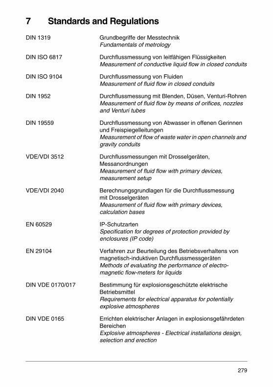
7 Standards and Regulations
DIN 1319 Grundbegriffe der Messtechnik Fundamentals of metrology
DIN ISO 6817 Durchflussmessung von leitfähigen Flüssigkeiten Measurement of conductive liquid flow in closed conduits
DIN ISO 9104 Durchflussmessung von Fluiden Measurement of fluid flow in closed conduits
DIN 1952 Durchflussmessung mit Blenden, Düsen, Venturi-RohrenMeasurement of fluid flow by means of orifices, nozzles and Venturi tubes
DIN 19559 Durchflussmessung von Abwasser in offenen Gerinnen und Freispiegelleitungen Measurement of flow of waste water in open channels and gravity conduits
VDE/VDI 3512 Durchflussmessungen mit Drosselgeräten, Messanordnungen Measurement of fluid flow with primary devices, measurement setup
VDE/VDI 2040 Berechnungsgrundlagen für die Durchflussmessung mit Drosselgeräten Measurement of fluid flow with primary devices, calculation bases
EN 60529 IP-Schutzarten Specification for degrees of protection provided by enclosures (IP code)
EN 29104 Verfahren zur Beurteilung des Betriebsverhaltens vonmagnetisch-induktiven Durchflussmessgeräten Methods of evaluating the performance of electro-magnetic flow-meters for liquids
DIN VDE 0170/017 Bestimmung für explosionsgeschützte elektrische Betriebsmittel Requirements for electrical apparatus for potentially explosive atmospheres
DIN VDE 0165 Errichten elektrischer Anlagen in explosionsgefährdetenBereichen Explosive atmospheres - Electrical installations design,selection and erection
279

DIN EN 50014 to 50020 Elektrische Betriebsmittel für explosionsgefährdete and 50028 Bereiche
Electrical apparatus for potentially explosive atmosphere
NAMUR NE 21 NAMUR-EmpfehlungElektro-magnetische Verträglichkeit NAMUR Recommendation Electromagnetic Compatibility (EMC)
280

8 Materials, Corrosion Resistance Tables
Included among the criteria for meter selection are the materials to be utilized. Of pri-mary interest are those materials which come in contact with the measuring medium.Also the ambient conditions must not be neglected where it is most important that hu-midity be considered.
Generally the user knows his measuring media so well that he can readily indicate suit-able materials. The following tables are provided for assistance. The listed informationis taken from manufacturers' publications. However, a guarantee for the completenessand correctness cannot be given.
The following list includes the available materials for the process-wetted parts in the in-dividual measuring devices.
Vortex Flowmeters:
Meter tube: Stainless steel 1.4571, Hastelloy CSensor: Stainless steel 1.4571, Hastelloy CShedder: Stainless steel 1.4571, Hastelloy CGasket: Graphite, PTFE, Viton A, Kalrez
Swirl Flowmeters:
Meter tube: Stainless steel 1.4571, Hastelloy CSensor: Stainless steel 1.4571, Hastelloy CShedder: Stainless steel 1.4571, Hastelloy CGasket: Graphite, PTFE, Viton A, Kalrez
Electromagnetic Flowmeters:
Liner Hard rubber, soft rubber, PFA, PTFE, Torlon, Peek,PVDF, Ceramic Carbide
Electrodes Stainless steel 1.4571, Hastelloy B, Hastelloy C, stainless steel 1.4539, Titanium, Tantalum, Platinum Iridium
Coriolis Mass Flowmeters:
Meter tube Stainless steel 1.4571, 1.4435, Hastelloy C
281
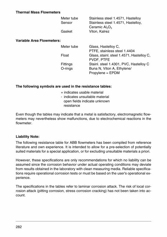
Thermal Mass Flowmeters
Meter tube Stainless steel 1.4571, HastelloySensor Stainless steel 1.4571, Hastelloy,
Ceramic Al2O3 Gasket Viton, Kalrez
Variable Area Flowmeters:
Meter tube Glass, Hastelloy C, PTFE, stainless steel 1.4404
Float Glass, stainl. steel 1.4571, Hastelloy C, PVDF, PTFE
Fittings Stainl. steel 1.4301, PVC, Hastelloy CO-rings Buna N, Viton A, Ethylene/
Propylene = EPDM
The following symbols are used in the resistance tables:
+ indicates usable material- indicates unsuitable material open fields indicate unknown resistance
Even though the tables may indicate that a metal is satisfactory, electromagnetic flow-meters may nevertheless show malfunctions, due to electrochemical reactions in theflowmeter.
Liability Note:
The following resistance table for ABB flowmeters has been compiled from referenceliterature and own experience. It is intended to allow for a pre-selection of potentiallysuited materials for a special application, or for excluding unsuitable materials a priori.
However, these specifications are only recommendations for which no liability can beassumed since the corrosion behavior under actual operating conditions may deviatefrom results obtained in the laboratory with clean measuring media. Reliable specifica-tions require operational corrosion tests or must be based on the user's operational ex-perience.
The specifications in the tables refer to laminar corrosion attack. The risk of local cor-rosion attack (pitting corrosion, stress corrosion cracking) has not been taken into ac-count.
282

Gas
eou
s/L
iqu
idE
lect
rica
l Co
nd
uct
ivit
y
Co
nce
ntr
atio
n (
%)
Tem
per
atu
re (
°C)
Metals Non-Metals
Sta
inl.
stee
l 1.4
301
Sta
inl.
stee
l 1.4
539
Sta
inl.
stee
l 1.4
541
Sta
inl.
stee
l 1.4
571
Has
tello
y B
Has
tello
y C
Tit
aniu
mT
anta
lum
Pla
tin
um
Har
d R
ub
ber
So
ft R
ub
ber
PF
AP
TF
EE
PD
MB
un
a N
Vit
on
AP
VD
FP
VC
Gla
ssA
I 2O
3
Acetic acid F - 100 40 + + + + + + + + + - - + + + - - - - + +
Acetic acid F + 50 80 + + + + + + + + + - - + + + + - + +
Acetic anhydride F + 100 20 + + + + + + + + + + + + + +
Acetylene G - 100 20 + + + + + + + + + + + + + + + +
Alum. chloride solution F + 30 70 - - - - + - - + + + + + + + + +
Alum. chloride solution F + 80 70 - - - - + - - + + + + + + +
Alum. sulfate solution F + 20 50 - - - + - + + + + + + + + + +
Alum. sulfate solution F + 50 50 - - - + - + + + + - - + + + +
Ammonia G - 100 50 + + + + + + + - + - - + + + + - - - + +
Ammonia solution F + 25 50 + + + + + + + - + - - + + + + + + + +
Aniline F - 100 25 + + + + - + + + + - - + + - + +
Argon G - 100 100 + + + + + + + + + + + + + + + + + + + +
Beer F + 10 + + + + + + + + + + + + + + + +
Benzene F - 100 50 + + + + + + + + + - - + + - - - - + +
Blood F + + + + + + + + + + + + + + + + + +
Brine F + 20 - - - - - + - + + + + + - + + + +
Bromine F - 100 20 - - - - - + - + + + + + - + +
Butane G - 100 50 + + + + + + + + + + + - + + - - + +
Butyl acetate F 100 50 + + + + + + + + + + + + - + - + +
Butyl alcohol F - 100 20 + + + + + + + + + + + + + + + +
Butylene G - 100 20 + + + + + + + + + + + + + + + + +
Calcium chloride solution F + 100 20 + + + + + + + + + + + + + + + + + +
Calcium hydroxide sol. F + 50 50 + + + + + + + - - + + + + + + + + +
Calcium hypochlor. sol. F + 20 50 - - - - - + + + + + + + + + +
Caprolactam F - 50 50 + + + + + - + +
Carbolic acid F - 90 50 - + + + + + + + + - - + + - - - + - + +
Carbon dioxide G - 100 50 + + + + + + + + + + + + + + + + + + +
Carbon tetrachloride F - 100 50 + + + + + + + + - - + + + - + + - + +
Carbonic acid F + 50 + + + + + + + + + + + + + + + + + - + +
Carboxylic acid, diluted F - 50 + + + + + + + + + + - + +
Chlorinated water F + 100 20 - - - + + - - + + + + + - + +
Chlorine dioxide, dry G - 100 20 + + + + - - + + + + +
283
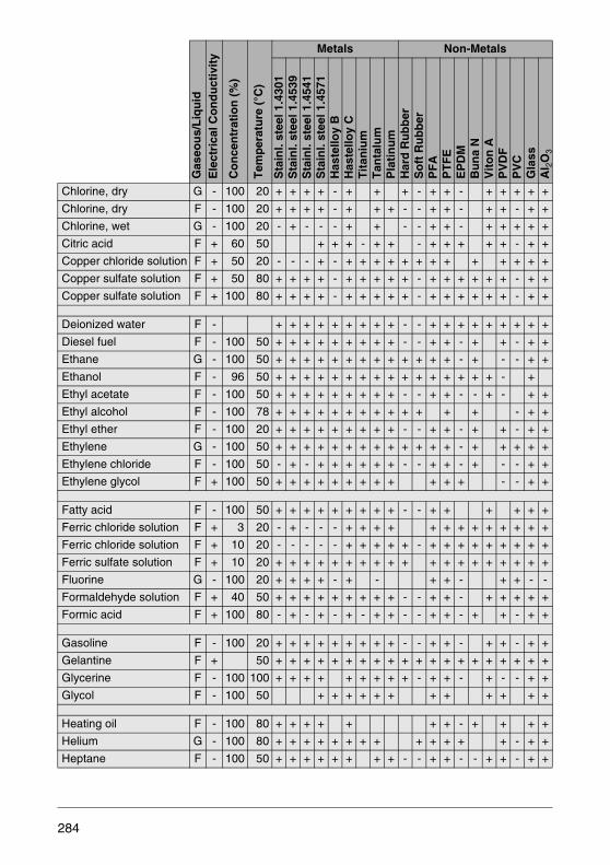
Chlorine, dry G - 100 20 + + + + - + + + - + + - + + + + +
Chlorine, dry F - 100 20 + + + + - + + + - - + + - + + - + +
Chlorine, wet G - 100 20 - + - - - + + - - + + - + + + + +
Citric acid F + 60 50 + + + - + + - + + + + + - + +
Copper chloride solution F + 50 20 - - - + - + + + + + + + + + + + + +
Copper sulfate solution F + 50 80 + + + + - + + + + + - + + + + + + - + +
Copper sulfate solution F + 100 80 + + + + - + + + + + - + + + + + + - + +
Deionized water F - + + + + + + + + + - - + + + + + + + + +
Diesel fuel F - 100 50 + + + + + + + + + - - + + - + + - + +
Ethane G - 100 50 + + + + + + + + + + + + + - + - - + +
Ethanol F - 96 50 + + + + + + + + + + + + + + + + - +
Ethyl acetate F - 100 50 + + + + + + + + + - - + + - - + - + +
Ethyl alcohol F - 100 78 + + + + + + + + + + + + + - + +
Ethyl ether F - 100 20 + + + + + + + + + - - + + - + + - + +
Ethylene G - 100 50 + + + + + + + + + + + + + - + + + + +
Ethylene chloride F - 100 50 - + - + + + + + + - - + + - + - - + +
Ethylene glycol F + 100 50 + + + + + + + + + + + + - - + +
Fatty acid F - 100 50 + + + + + + + + + - - + + + + + +
Ferric chloride solution F + 3 20 - + - - - + + + + + + + + + + + + +
Ferric chloride solution F + 10 20 - - - - - + + + + + - + + + + + + + + +
Ferric sulfate solution F + 10 20 + + + + + + + + + + + + + + + + + + +
Fluorine G - 100 20 + + + + - + - + + - + + - -
Formaldehyde solution F + 40 50 + + + + + + + + + - - + + - + + + + +
Formic acid F + 100 80 - + - + - + - + + - - + + - + + - + +
Gasoline F - 100 20 + + + + + + + + + - - + + - + + - + +
Gelantine F + 50 + + + + + + + + + + + + + + + + + + + +
Glycerine F - 100 100 + + + + + + + + + - + + - + - - + +
Glycol F - 100 50 + + + + + + + + + + + +
Heating oil F - 100 80 + + + + + + + - + + + +
Helium G - 100 80 + + + + + + + + + + + + + - + +
Heptane F - 100 50 + + + + + + + + - - + + - - + + - + +
Gas
eou
s/L
iqu
idE
lect
rica
l Co
nd
uct
ivit
y
Co
nce
ntr
atio
n (
%)
Tem
per
atu
re (
°C)
Metals Non-Metals
Sta
inl.
stee
l 1.4
301
Sta
inl.
stee
l 1.4
539
Sta
inl.
stee
l 1.4
541
Sta
inl.
stee
l 1.4
571
Has
tello
y B
Has
tello
y C
Tit
aniu
mT
anta
lum
Pla
tin
um
Har
d R
ub
ber
So
ft R
ub
ber
PF
AP
TF
EE
PD
MB
un
a N
Vit
on
AP
VD
FP
VC
Gla
ssA
I 2O
3
284

Hexane F - 100 50 + + + + + + + + + + - + + - + +
Hydrazine solution F + 25 20 + - + - + - - + + + - + + - -
Hydrobromic acid F + 48 50 - - - - + - - + + + + + + - + + + +
Hydrochloric acid F + 10 50 - - - - + - + + + + - + + - - + + + + +
Hydrochloric acid F + 37 20 - - - - + + - + + + - + + - - + + + + +
Hydrocyanic acid F + 100 20 + + + + + + + + + - - + + + + + +
Hydrofluoric acid F + 40 20 - - - - - + - - + + - + + - - - + + - -
Hydrofluoric acid F + 70 20 - - - - - + - - + - - + + - - - + - - -
Hydrogen G - 100 50 + + + + + + + + + + + + + + + + +
Hydrogen chloride G - 100 20 - + + + + + + + - - + + + + + + +
Hydrogen peroxide sol. F + 40 20 + + + + + - + - - - + + + + + - +
Hydrogen sulfide, dry G - 100 20 + + + + - + + + + + + + + + + + - + +
Kerosine F - 100 20 + + + + + + +
Krypton G - 100 50 + + + + + + + + + + + + + - + - - + +
Magnesium chloride s. F + 50 20 - - - - + + + + + + + + + + + + + + + +
Magnesium sulfate sol. F + 20 50 + + + + + - + + + + + + + + + + + + +
Malic acid F + 50 50 + + + + + + + + + + + + + + + + + + +
Methane G - 100 50 + + + + + + + + + + + + + - + + - - + +
Methanol = Methyl alc. F - 100 50 + + + + + + + + + + + + + + + - + - + +
Methylbenzene = Toluol F - 100 50 + + + + + + - - + + - - + + - + +
Methylene chloride G - 100 20 + + + + + + + + + - - + + - - - - - + +
Monochloroacetic acid F + 70 50 + + + + + + - - + + + - - - + +
Natural gas, dry G - 100 40 + + + + + + + + + - - + + - + + + + +
Neon G - 100 100 + + + + + + + + + + + + + +
Nitric acid F + 20 40 + + + + - + + + + - - + + - - - + + + +
Nitric acid F + 70 50 - + + + - - + + + - - + + - - - + - + +
Nitrogen G - 100 50 + + + + + + + + + + + + + + - - + +
Oleum F + 10 50 - - - - + - - - + - - + - - + - - + +
Oleum F + 20 20 - - - - + - - + + - - + - - + - - + +
Olive oil F - 50 + + + + + + + + + + - + + + + + - + +
Oxalic acid solution F + 10 50 - + - + + + - + + + - + + + + + - + +
Gas
eou
s/L
iqu
idE
lect
rica
l Co
nd
uct
ivit
y
Co
nce
ntr
atio
n (
%)
Tem
per
atu
re (
°C)
Metals Non-Metals
Sta
inl.
stee
l 1.4
301
Sta
inl.
stee
l 1.4
539
Sta
inl.
stee
l 1.4
541
Sta
inl.
stee
l 1.4
571
Has
tello
y B
Has
tello
y C
Tit
aniu
mT
anta
lum
Pla
tin
um
Har
d R
ub
ber
So
ft R
ub
ber
PF
AP
TF
EE
PD
MB
un
a N
Vit
on
AP
VD
FP
VC
Gla
ssA
I 2O
3
285
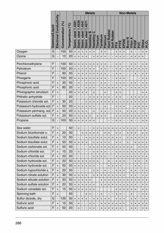
Oxygen G - 100 50 + + + + + + + + + + + + - - + +
Ozone G - 10 20 + + + + + + + + - - + + + - + + + +
Perchloroethylene F - 100 50 + + + + + + + + + - - + + - - + + - + +
Petroleum F - 100 20 + + + + + + + + - - + + - + + + + + +
Phenol F - 90 50 - + + + + + + + + - - + + - - - + - + +
Phosgene F - 100 20 + + + + + + + + + - - + + + - - + +
Phosphoric acid F + 30 50 - + - + + + - + + - - + + + - + + - + +
Phosphoric acid F + 80 20 - + - + + + - + + + + + + - - + + + + +
Photographic emulsion F + 20 + + + + + + + + + +
Phthalic anhydride F - 20 - - - - + + + + + + - + + - + + + + +
Potassium chloride sol. F + 30 20 - - - + + + + + + + + + + + + + + + + +
Potassium hydroxide sol. F + 50 20 + + + + + + - - + + + + - + + + +
Potassium permang. sol. F + 50 20 + + + + + + + - - + + + + + - +
Potassium sulfate sol. F + 20 50 + + + + + + + + + + + + + + + + +
Propane G - 100 50 + + + + + + - - + + - - + - - + +
Sea water F + 50 - + - - - + + + + + + + + + + + + - + +
Sodium bicarbonate s. F + 20 50 + + + + + + + + + + + + + +
Sodium bisulfate solut. F + 10 50 - - - + + + + + + + + + + + + + + + +
Sodium bisulfate solut. F + 50 50 + + + + + + + + + + + + + + + +
Sodium carbonate sol. F + 50 50 - - - - + + + + + + + + + + + + + + +
Sodium chloride sol. F + 10 20 - + - - - + + + + - - + + + + + + + + +
Sodium chloride sol. F + 20 20 - - - - - + + + + - - + + + + + + + + +
Sodium hydroxide sol. F + 20 50 + + + + + + + - + - + + + - - + + - +
Sodium hydroxide sol. F + 50 50 + + + + + + - - + + + + - - - + + - -
Sodium hypochloride s. F + 20 50 - - - - + + - + - - + + + + + - + +
Sodium nitrate solution F + 30 50 + + + + + + + + + + + + + + + - + +
Sodium silicate solution F + 30 50 + + + + + + + + + + + + + + + + + +
Sodium sulfate solution F + 20 50 + + + + + + + + + + + + + + + + - + +
Sodium vanadate sol. F + 10 50 + + + + + + + + + + + + + +
Spinning bath F + 50 + + - - + - - + + - + - + +
Sulfur dioxide, dry G - 100 50 + + + + - + + + + + + + + + + - + +
Sulfuric acid F + 10 50 - + - - + + - + + + + + + + + + + + +
Sulfuric acid F + 50 20 - + - - + + - + + + + + + - + + - + +
Gas
eou
s/L
iqu
idE
lect
rica
l Co
nd
uct
ivit
y
Co
nce
ntr
atio
n (
%)
Tem
per
atu
re (
°C)
Metals Non-Metals
Sta
inl.
stee
l 1.4
301
Sta
inl.
stee
l 1.4
539
Sta
inl.
stee
l 1.4
541
Sta
inl.
stee
l 1.4
571
Has
tello
y B
Has
tello
y C
Tit
aniu
mT
anta
lum
Pla
tin
um
Har
d R
ub
ber
So
ft R
ub
ber
PF
AP
TF
EE
PD
MB
un
a N
Vit
on
AP
VD
FP
VC
Gla
ssA
I 2O
3
286
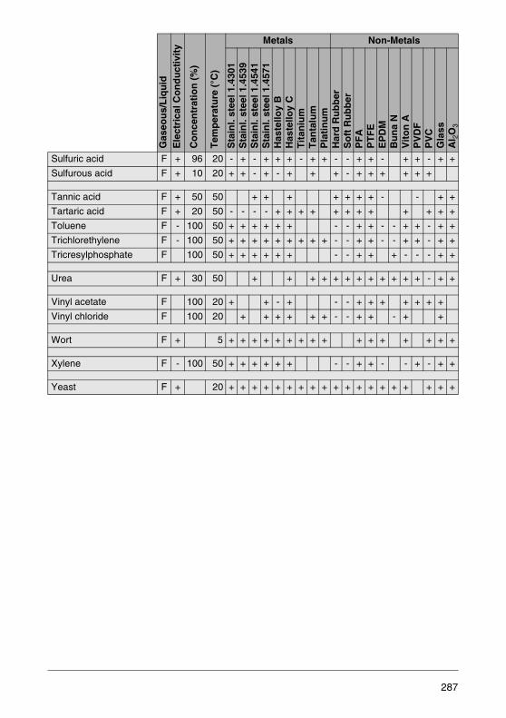
Sulfuric acid F + 96 20 - + - + + + - + + - - + + - + + - + +
Sulfurous acid F + 10 20 + + - + - + + + - + + + + + +
Tannic acid F + 50 50 + + + + + + + - - + +
Tartaric acid F + 20 50 - - - - + + + + + + + + + + + +
Toluene F - 100 50 + + + + + + - - + + - - + + - + +
Trichlorethylene F - 100 50 + + + + + + + + + - - + + - - + + - + +
Tricresylphosphate F 100 50 + + + + + + - - + + + - - - + +
Urea F + 30 50 + + + + + + + + + + + + - + +
Vinyl acetate F 100 20 + + - + - - + + + + + + +
Vinyl chloride F 100 20 + + + + + + - - + + - + +
Wort F + 5 + + + + + + + + + + + + + + + +
Xylene F - 100 50 + + + + + + - - + + - - + - + +
Yeast F + 20 + + + + + + + + + + + + + + + + + + +
Gas
eou
s/L
iqu
idE
lect
rica
l Co
nd
uct
ivit
y
Co
nce
ntr
atio
n (
%)
Tem
per
atu
re (
°C)
Metals Non-Metals
Sta
inl.
stee
l 1.4
301
Sta
inl.
stee
l 1.4
539
Sta
inl.
stee
l 1.4
541
Sta
inl.
stee
l 1.4
571
Has
tello
y B
Has
tello
y C
Tit
aniu
mT
anta
lum
Pla
tin
um
Har
d R
ub
ber
So
ft R
ub
ber
PF
AP
TF
EE
PD
MB
un
a N
Vit
on
AP
VD
FP
VC
Gla
ssA
I 2O
3
287


9 References
Eck, Bruno „Technische Strömungslehre“[Technical Fluid Mechanics] Springer-Verlag, Berlin
Hengstenberg, Sturm, „Messen, Steuern, Regeln in der Chemischen Technik“Winkler [Measurements, Control, Regulation in Chemical Processes]
Springer-Verlag, Berlin
Kalide, Wolfgang „Einführung in die technische Strömungslehre“[Introduction to Technical Fluid Mechanics] Carl Hauser Verlag, München
Naudascher, Eduard „Hydraulik der Gerinne und Gerinnebauwerke“[Open Channel and Channel Structure Hydraulics] Springer-Verlag, Wien, New York
Company Technical Literature:ABB Automation ProductsAerzener MaschinenbaufabrikBopp und ReutherDanfossMeineckeSiemens
Dechema-Werkstofftabelle: Dechema Frankfurt/Main[Materials table]
289

The features and characteristics of the most important methods of
measuring the flowrate and quantities of flowing fluids are described
and compared.
Numerous practical details provide the user with valuable information
about flow metering in industrial applications.
Ind
ustr
ial flo
w m
easu
rem
en
t
Industrial flow measurement Basics and practice
D1
84
B0
75
U0
2 R
ev.
08
09
.20
11
Top Related