


Languages
Pages
Legal

[email protected] | Tel: +39 (0) 41 9637540 | www.engys.eu
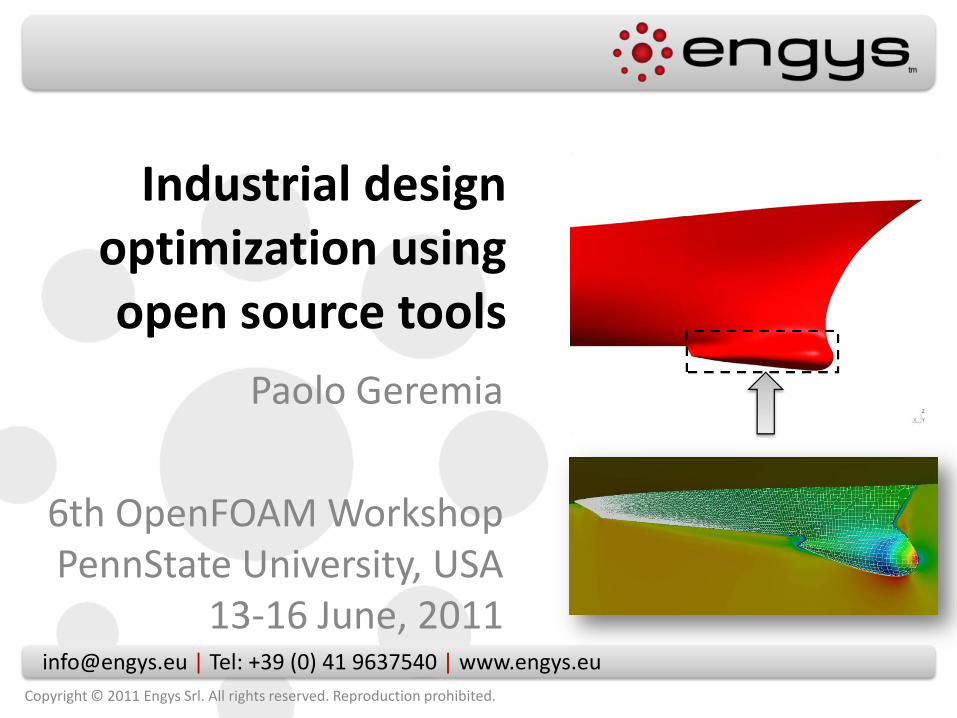
Industrial design optimization using open source tools
Paolo Geremia
6th OpenFOAM WorkshopPennState University, USA
13-16 June, 2011
Copyright © 2011 Engys Srl. All rights reserved. Reproduction prohibited.
Contents
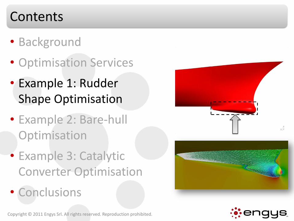
• Background
• Optimisation Services
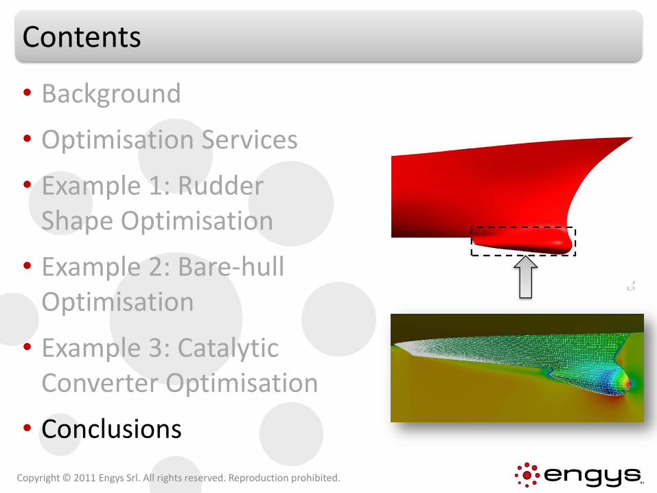
• Example 1: Rudder Shape Optimisation
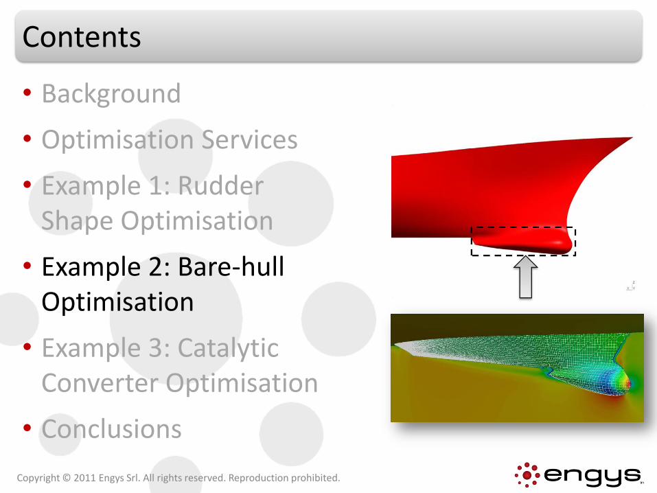
• Example 2: Bare-hull Optimisation
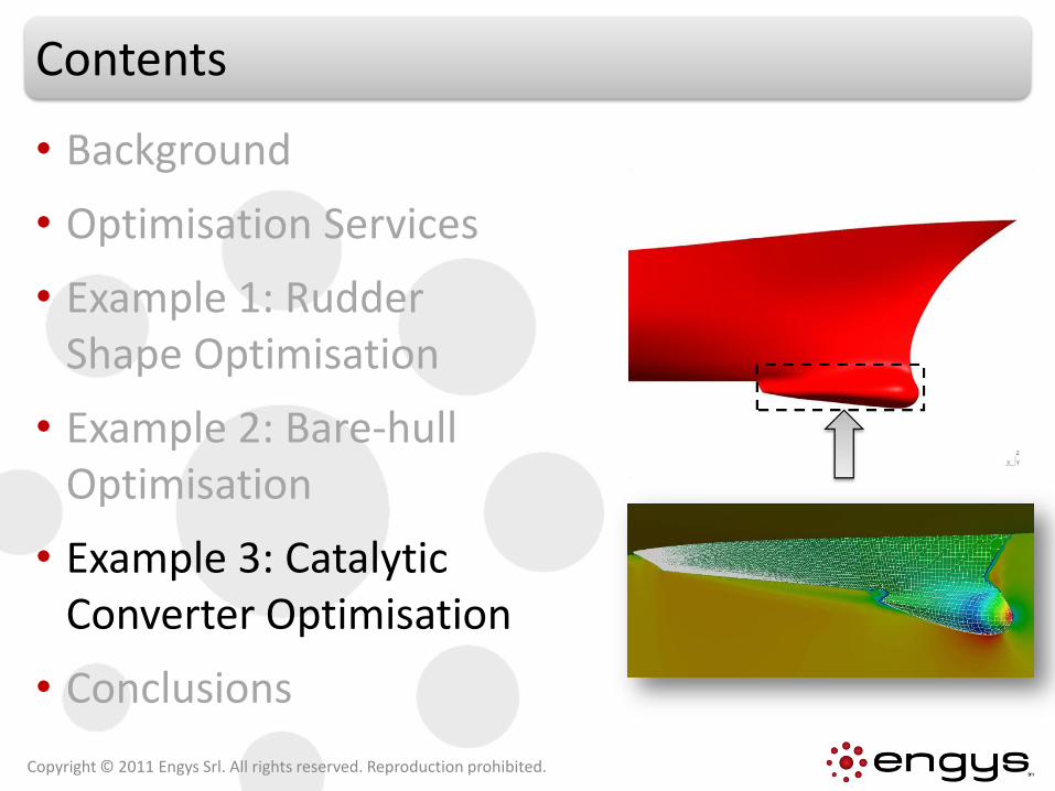
• Example 3: Catalytic Converter Optimisation
• Conclusions
Copyright © 2011 Engys Srl. All rights reserved. Reproduction prohibited.
Background
• 8+ years experience managing industrial CAE projects involving Multi-Disciplinary Optimisation methods
• 10+ years track-record using, developing and supporting FOAM/OPENFOAM® for industry
• Main optimisation platforms → modeFRONTIER (ESTECO)DAKOTA(Sandia OSS)
• More than 30 publications to date on multi-disciplinary optimisation(real industrial applications and proof-of-concept)
Copyright © 2011 Engys Srl. All rights reserved. Reproduction prohibited.
Why Optimisation?
• Multi-objective design optimisation techniques are ideal for:
Finding the optimal layout of the design solution
Automating the design process instead of trial-and-error approach
Multi-disciplinary process integration (e.g. CAD+Mesh+FEM+CFD)
Finding the most relevant design parameters affecting the solution
Evaluating the robustness and stability of a solution for a given range of parameters
Better understanding of design space response
Better design with reduction of costs and speed-up of time-to-market
Copyright © 2011 Engys Srl. All rights reserved. Reproduction prohibited.
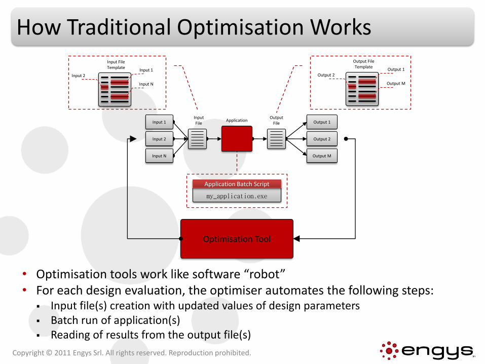
How Traditional Optimisation Works
• Optimisation tools work like software “robot”• For each design evaluation, the optimiser automates the following steps:
Input file(s) creation with updated values of design parameters Batch run of application(s) Reading of results from the output file(s)
Copyright © 2011 Engys Srl. All rights reserved. Reproduction prohibited.
Output 1
Output 2
Output M
Input 1
Input 2
Input N
Input File
Output File
Application
Input File Template
Input 2Input 1
Input N
Output File Template
Output 2Output 1
Output M
my_application.exe
Application Batch Script
Optimisation Tool
Contents
• Background
• Optimisation Services
• Example 1: Rudder Shape Optimisation
• Example 2: Bare-hull Optimisation
• Example 3: Catalytic Converter Optimisation
• Conclusions
Copyright © 2011 Engys Srl. All rights reserved. Reproduction prohibited.
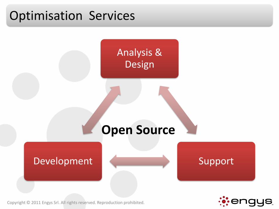
Optimisation Services
Analysis & Design
SupportDevelopment
Open Source
Copyright © 2011 Engys Srl. All rights reserved. Reproduction prohibited.
Optimisation Services
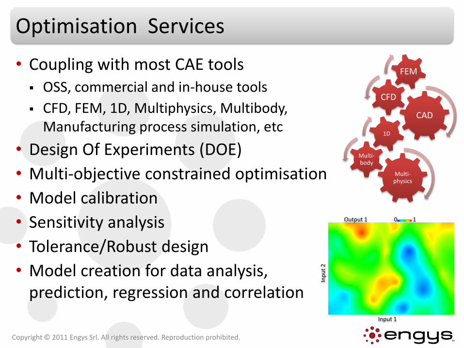
• Coupling with most CAE tools OSS, commercial and in-house tools
CFD, FEM, 1D, Multiphysics, Multibody, Manufacturing process simulation, etc
• Design Of Experiments (DOE)
• Multi-objective constrained optimisation
• Model calibration
• Sensitivity analysis
• Tolerance/Robust design
• Model creation for data analysis, prediction, regression and correlation
Copyright © 2011 Engys Srl. All rights reserved. Reproduction prohibited.
CAD
CFD
FEM
Multi-physics
Multi-body
1D
Input 1In
pu
t 2
0 1Output 1
Contents
• Background
• Optimisation Services
• Example 1: Rudder Shape Optimisation
• Example 2: Bare-hull Optimisation
• Example 3: Catalytic Converter Optimisation
• Conclusions
Copyright © 2011 Engys Srl. All rights reserved. Reproduction prohibited.

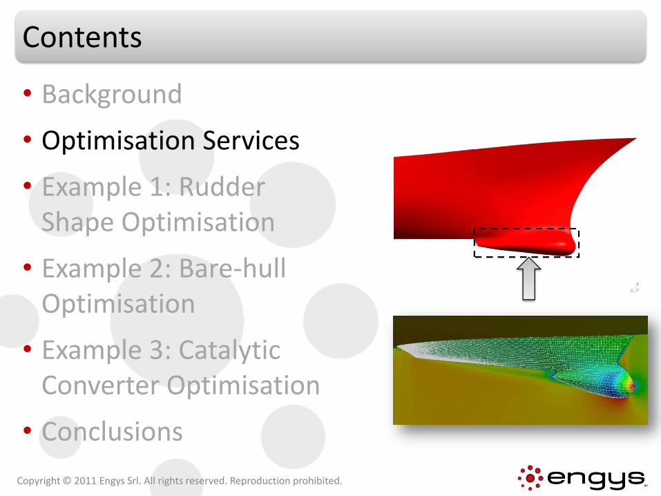
Example 1 | Rudder Shape Optimisation
• US Navy surface combatant ca. 1980 - Model 5415
• Twin open-water propellers driven by shafts supported by struts
• Optimisation problem: minimise forward resistance and maximise lift of 2D rudder hydrofoil
Copyright © 2011 Engys Srl. All rights reserved. Reproduction prohibited.
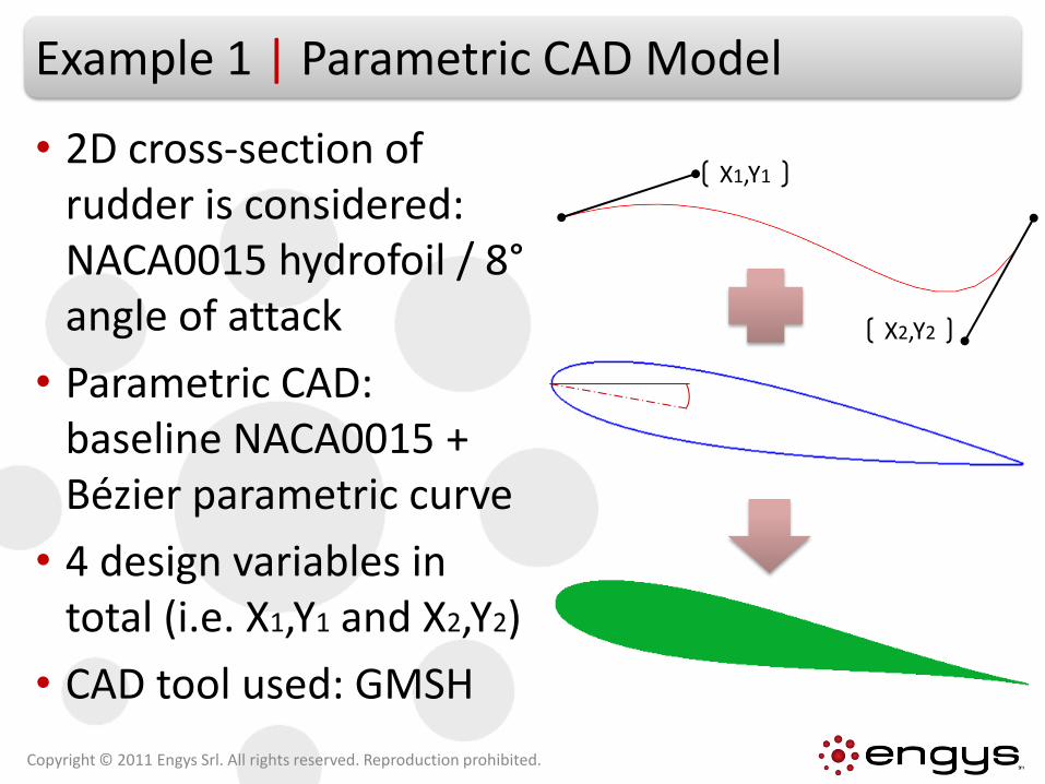
Example 1 | Parametric CAD Model
• 2D cross-section of rudder is considered: NACA0015 hydrofoil / 8°angle of attack
• Parametric CAD: baseline NACA0015 + Bézier parametric curve
• 4 design variables in total (i.e. X1,Y1 and X2,Y2)
• CAD tool used: GMSH
Copyright © 2011 Engys Srl. All rights reserved. Reproduction prohibited.
X1,Y1
X2,Y2
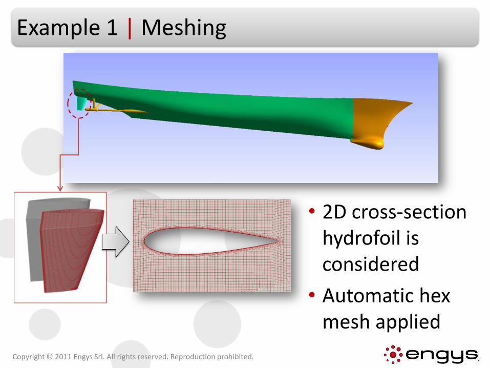
Example 1 | Meshing
• 2D cross-section hydrofoil is considered
• Automatic hex mesh applied
Copyright © 2011 Engys Srl. All rights reserved. Reproduction prohibited.
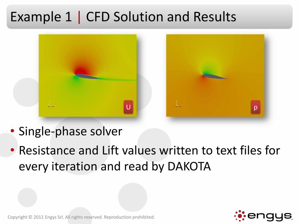
Example 1 | CFD Solution and Results
• Single-phase solver
• Resistance and Lift values written to text files for every iteration and read by DAKOTA
Copyright © 2011 Engys Srl. All rights reserved. Reproduction prohibited.
U p
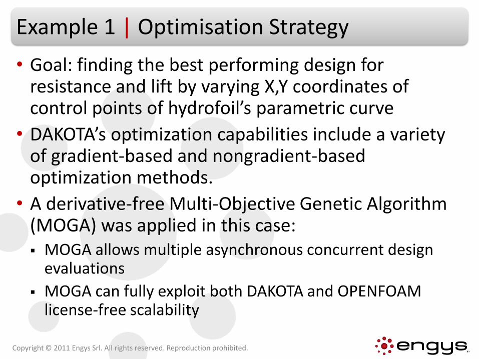
Example 1 | Optimisation Strategy
• Goal: finding the best performing design for resistance and lift by varying X,Y coordinates of control points of hydrofoil’s parametric curve
• DAKOTA’s optimization capabilities include a variety of gradient-based and nongradient-based optimization methods.
• A derivative-free Multi-Objective Genetic Algorithm (MOGA) was applied in this case: MOGA allows multiple asynchronous concurrent design
evaluations
MOGA can fully exploit both DAKOTA and OPENFOAM license-free scalability
Copyright © 2011 Engys Srl. All rights reserved. Reproduction prohibited.
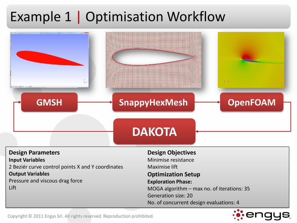
Example 1 | Optimisation Workflow
SnappyHexMeshGMSH
DAKOTA
OpenFOAM
Design ParametersInput Variables2 Beziér curve control points X and Y coordinates Output VariablesPressure and viscous drag forceLift
Design ObjectivesMinimise resistanceMaximise lift
Optimization Setup Exploration Phase:MOGA algorithm – max no. of iterations: 35Generation size: 20No. of concurrent design evaluations: 4
Copyright © 2011 Engys Srl. All rights reserved. Reproduction prohibited.
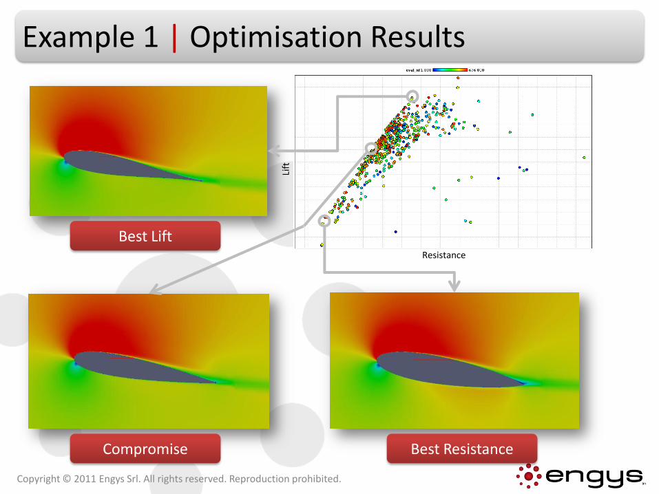
Example 1 | Optimisation Results
Copyright © 2011 Engys Srl. All rights reserved. Reproduction prohibited.
Resistance
Lift
Best ResistanceCompromise
Best Lift
Contents
• Background
• Optimisation Services
• Example 1: Rudder Shape Optimisation
• Example 2: Bare-hull Optimisation
• Example 3: Catalytic Converter Optimisation
• Conclusions
Copyright © 2011 Engys Srl. All rights reserved. Reproduction prohibited.
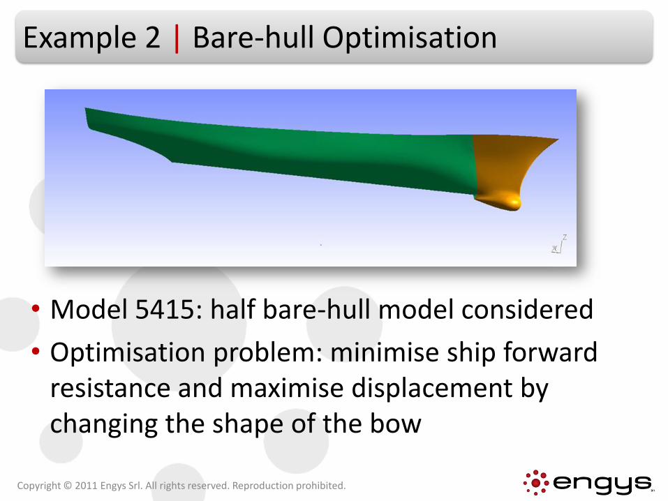
Example 2 | Bare-hull Optimisation
• Model 5415: half bare-hull model considered
• Optimisation problem: minimise ship forward resistance and maximise displacement by changing the shape of the bow
Copyright © 2011 Engys Srl. All rights reserved. Reproduction prohibited.
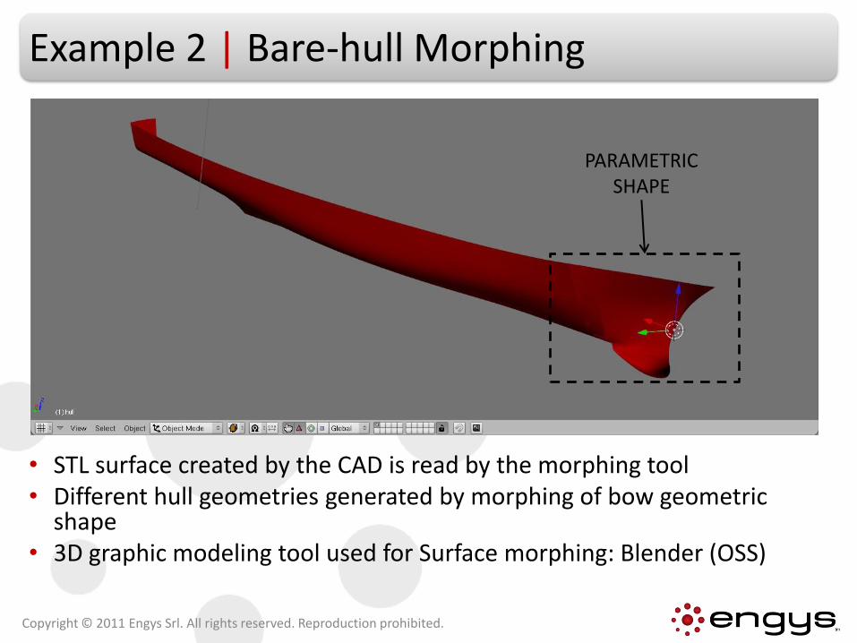
Example 2 | Bare-hull Morphing
• STL surface created by the CAD is read by the morphing tool• Different hull geometries generated by morphing of bow geometric
shape• 3D graphic modeling tool used for Surface morphing: Blender (OSS)
Copyright © 2011 Engys Srl. All rights reserved. Reproduction prohibited.
PARAMETRIC SHAPE
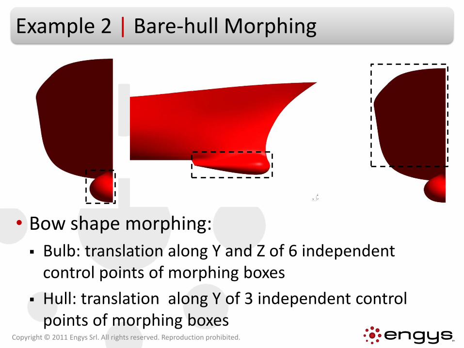
Example 2 | Bare-hull Morphing
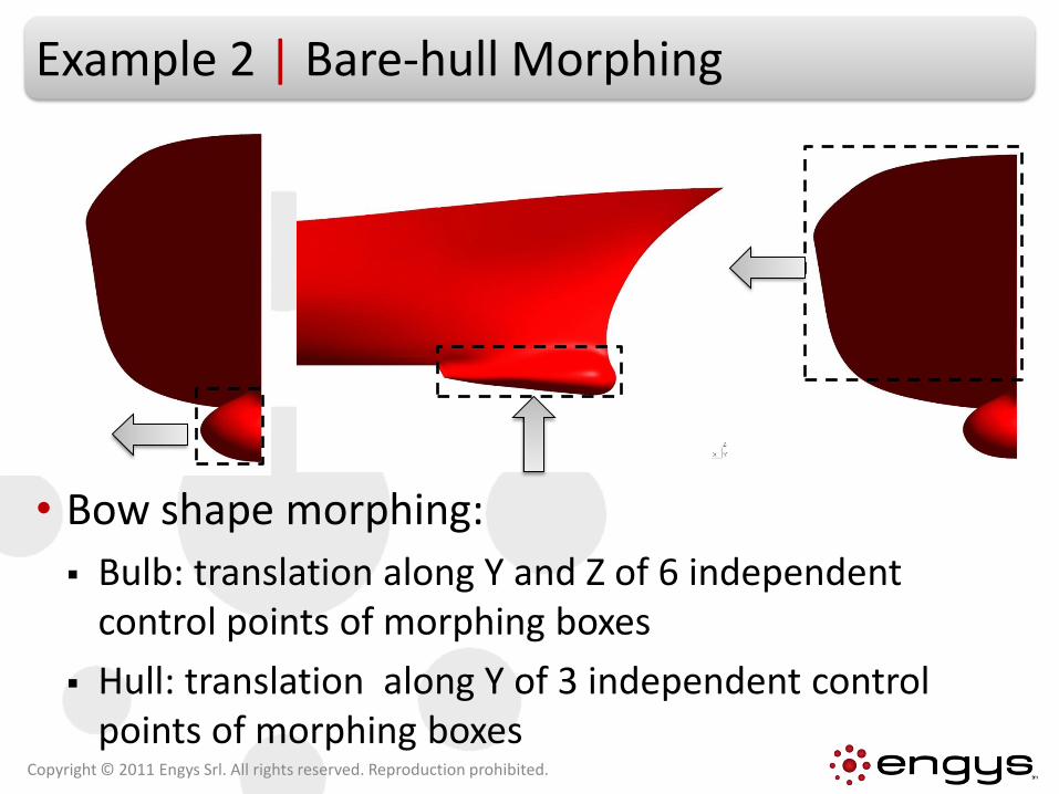
• Bow shape morphing:
Bulb: translation along Y and Z of 6 independent control points of morphing boxes
Hull: translation along Y of 3 independent control points of morphing boxes
Copyright © 2011 Engys Srl. All rights reserved. Reproduction prohibited.
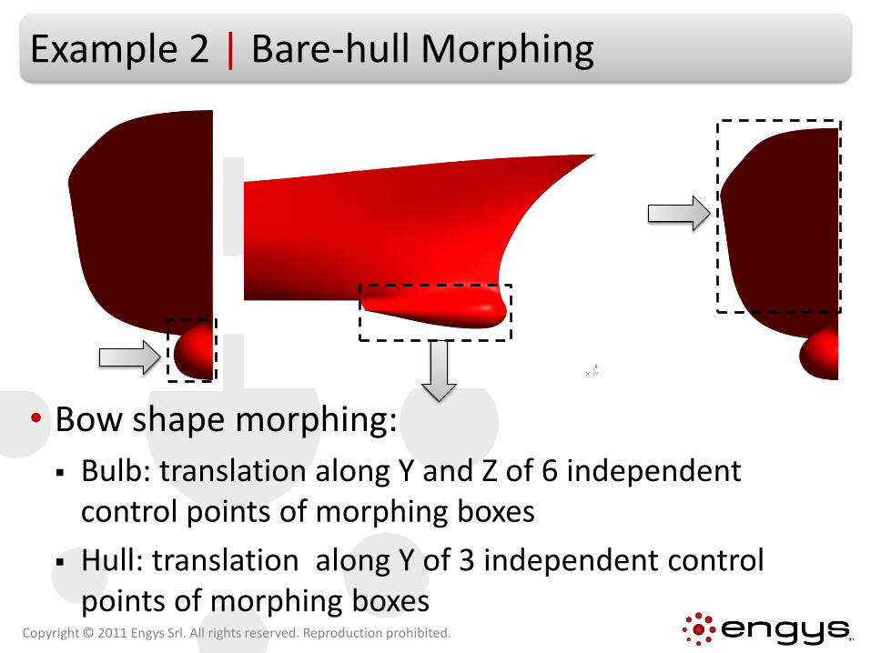
Example 2 | Bare-hull Morphing
• Bow shape morphing:
Bulb: translation along Y and Z of 6 independent control points of morphing boxes
Hull: translation along Y of 3 independent control points of morphing boxes
Copyright © 2011 Engys Srl. All rights reserved. Reproduction prohibited.
Example 2 | Bare-hull Morphing
• Bow shape morphing:
Bulb: translation along Y and Z of 6 independent control points of morphing boxes
Hull: translation along Y of 3 independent control points of morphing boxes
Copyright © 2011 Engys Srl. All rights reserved. Reproduction prohibited.
Example 2 | Bare-hull Mesh
Copyright © 2011 Engys Srl. All rights reserved. Reproduction prohibited.
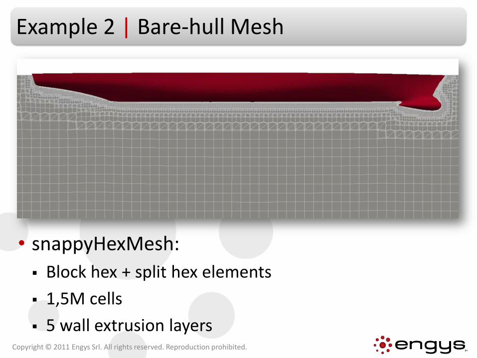
• snappyHexMesh:
Block hex + split hex elements
1,5M cells
5 wall extrusion layers
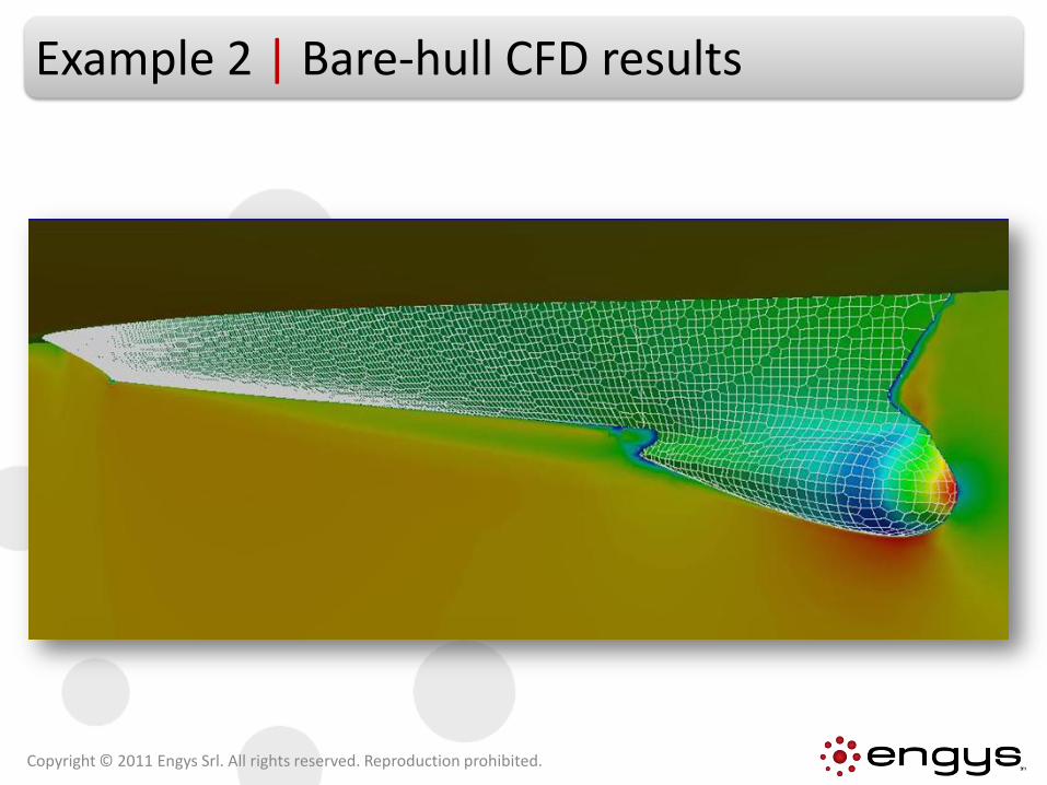
Example 2 | Bare-hull CFD results
Copyright © 2011 Engys Srl. All rights reserved. Reproduction prohibited.
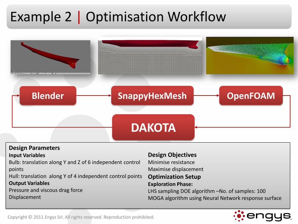
Example 2 | Optimisation Workflow
SnappyHexMeshBlender
DAKOTA
OpenFOAM
Design ParametersInput VariablesBulb: translation along Y and Z of 6 independent control pointsHull: translation along Y of 4 independent control pointsOutput VariablesPressure and viscous drag forceDisplacement
Design ObjectivesMinimise resistanceMaximise displacement
Optimization Setup Exploration Phase:LHS sampling DOE algorithm –No. of samples: 100MOGA algorithm using Neural Network response surface
Copyright © 2011 Engys Srl. All rights reserved. Reproduction prohibited.
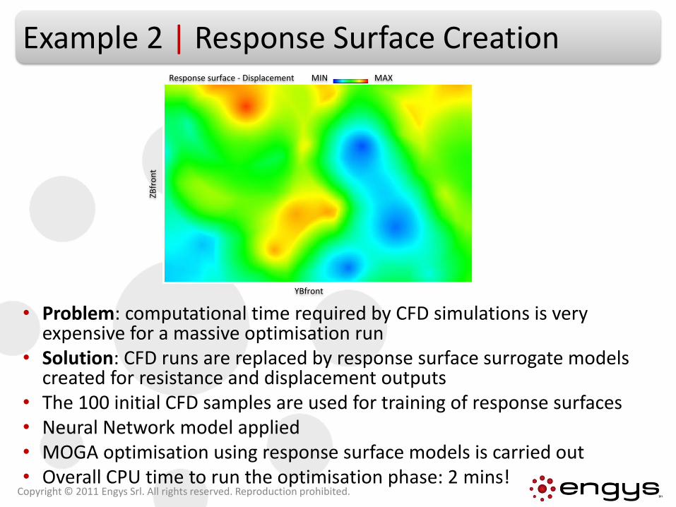
Example 2 | Response Surface Creation
• Problem: computational time required by CFD simulations is very expensive for a massive optimisation run
• Solution: CFD runs are replaced by response surface surrogate models created for resistance and displacement outputs
• The 100 initial CFD samples are used for training of response surfaces• Neural Network model applied• MOGA optimisation using response surface models is carried out• Overall CPU time to run the optimisation phase: 2 mins!
Copyright © 2011 Engys Srl. All rights reserved. Reproduction prohibited.
YBfront
ZBfr
on
t
MIN MAXResponse surface - Displacement
Example 2 | Bare-hull Optimal Shape
Copyright © 2011 Engys Srl. All rights reserved. Reproduction prohibited.
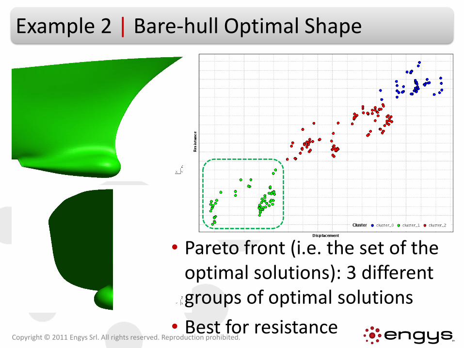
• Pareto front (i.e. the set of the optimal solutions): 3 different groups of optimal solutions
• Best for resistance
Example 2 | Bare-hull Optimal Shape
Copyright © 2011 Engys Srl. All rights reserved. Reproduction prohibited.
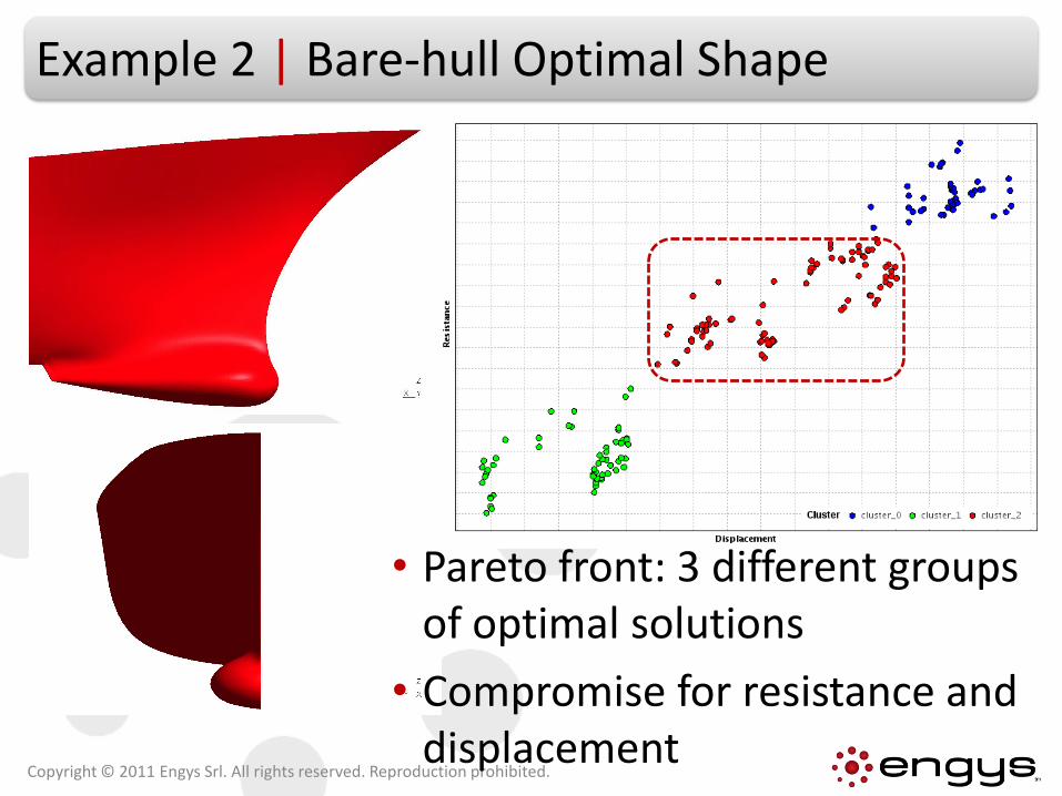
• Pareto front: 3 different groups of optimal solutions
• Compromise for resistance and displacement
Example 2 | Bare-hull Optimal Shape
Copyright © 2011 Engys Srl. All rights reserved. Reproduction prohibited.
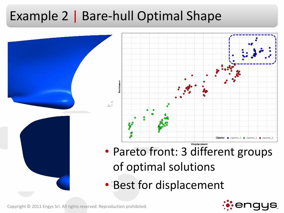
• Pareto front: 3 different groups of optimal solutions
• Best for displacement
Contents
• Background
• Optimisation Services
• Example 1: Rudder Shape Optimisation
• Example 2: Bare-hull Optimisation
• Example 3: Catalytic Converter Optimisation
• Conclusions
Copyright © 2011 Engys Srl. All rights reserved. Reproduction prohibited.
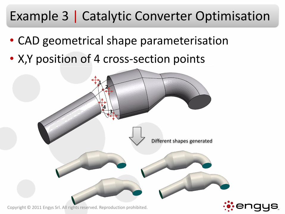
Example 3 | Catalytic Converter Optimisation
• CAD geometrical shape parameterisation
• X,Y position of 4 cross-section points
12
34
Different shapes generated
Copyright © 2011 Engys Srl. All rights reserved. Reproduction prohibited.
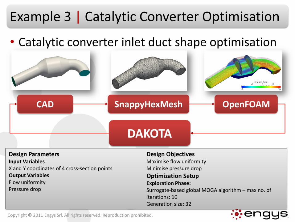
Example 3 | Catalytic Converter Optimisation
• Catalytic converter inlet duct shape optimisation
Copyright © 2011 Engys Srl. All rights reserved. Reproduction prohibited.
SnappyHexMeshCAD
DAKOTA
OpenFOAM
Design ParametersInput VariablesX and Y coordinates of 4 cross-section pointsOutput VariablesFlow uniformityPressure drop
Design ObjectivesMaximise flow uniformityMinimise pressure drop
Optimization Setup Exploration Phase:Surrogate-based global MOGA algorithm – max no. of iterations: 10Generation size: 32
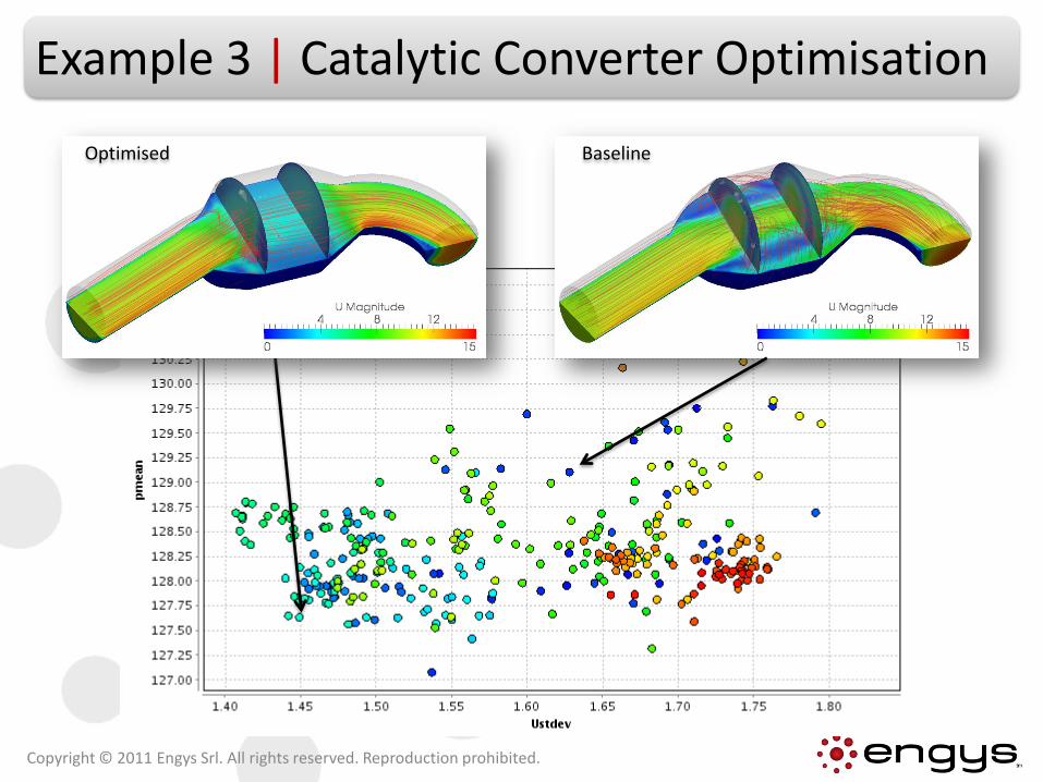
Example 3 | Catalytic Converter Optimisation
Copyright © 2011 Engys Srl. All rights reserved. Reproduction prohibited.
BaselineOptimised
Contents
• Background
• Optimisation Services
• Example 1: Rudder Shape Optimisation
• Example 2: Bare-hull Optimisation
• Example 3: Catalytic Converter Optimisation
• Conclusions
Copyright © 2011 Engys Srl. All rights reserved. Reproduction prohibited.
Conclusions
• The coupling between OSS DAKOTA and OPENFOAM was done successfully.
• Different shape parameterisation techniques were evaluated.
• DAKOTA capabilities were efficiently exploited for different naval and marine applications.
• Benefits of DAKOTA and OPENFOAM scalability are huge for product development speed-up and reduction in costs.
Copyright © 2011 Engys Srl. All rights reserved. Reproduction prohibited.
Disclaimer
Copyright © 2011 Engys Srl. All rights reserved. Reproduction prohibited.
[email protected] | Tel: +39 (0)41 9637540 | www.engys.eu
This document is the property of Engys Srl. Its contents, in whole orin part, are supplied in confidence and may not be copied,reproduced, translated, transferred, or reduced to any form,including electronic medium or machine-readable form, ortransmitted or publicly performed by any means, electronic orotherwise, without written authorisation issued by Engys Srl.Unauthorised distribution or use may give rise to a claim fordamages and/or be a criminal offence.
OPENFOAM® and OpenCFD® are registered trade marks of OpenCFD Ltd.None of Engys offerings are approved or endorsed by OpenCFD Limited, the producer of
the OpenFOAM software and owner of the OPENFOAM® and OpenCFD® trademarks.
Top Related