


Languages
Pages
Legal


Digital Control of Electric Drives
BE1M14DEP 1
Induction Motor Vector Control
Czech Technical University in Prague – Faculty of Electrical Engineering
O. Zoubek, J. Zdenek

2
● Scalar control● Vector control
Induction Motor Control Methods
BE1M14DEP 2

3
Three-phase Inverter
BE1M14DEP 3
4
● Disadvantages of scalar (U/f) control:
● Very low dynamics
Changes in the asynchronous machine take place at the speed given by the rotor time constant (ie, up to seconds on large machines)
● The input is the frequency - it is not possible to directly control of IM torque
● Not suitable for traction
● The motor torque is dependent on the slip frequency - it is still the same (the percentage with the lower output frequency of the drive increases)
● Advantages of scalar (U / f:) control:
● Simplicity of management (especially development)
Scalar Control Properties (U/f Method)
BE1M14DEP 4
5
Scalar Control - U/f Method)
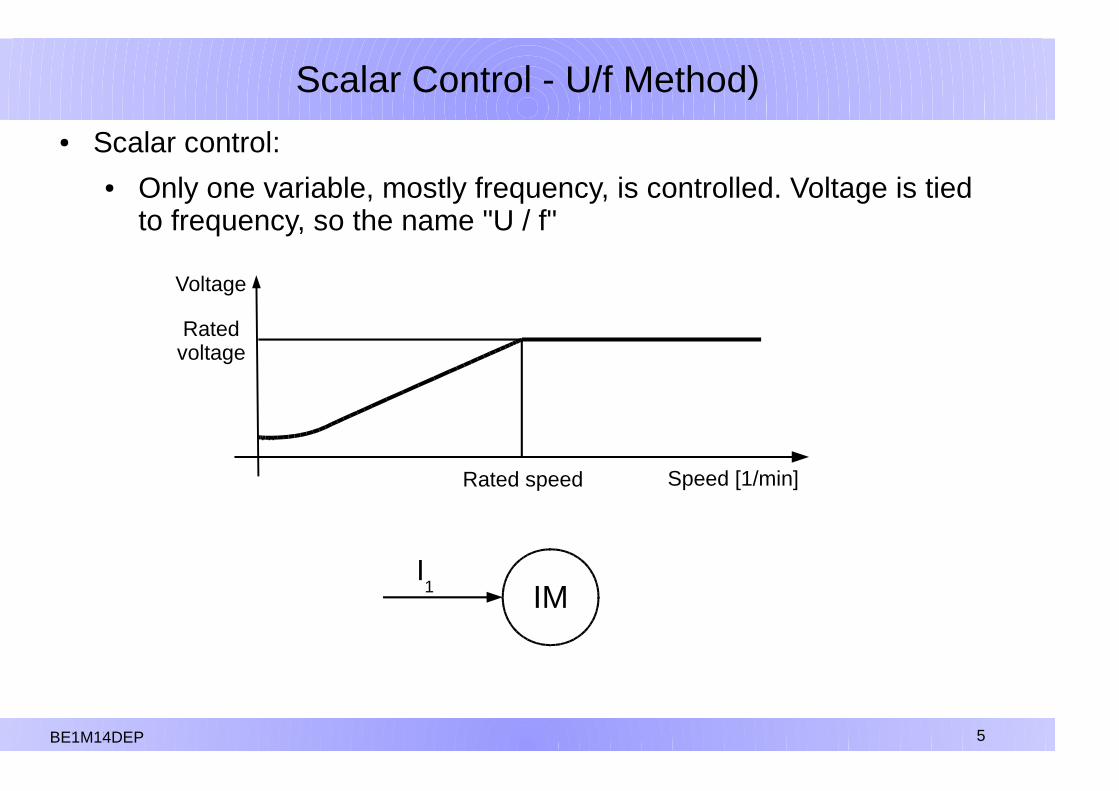
● Scalar control:● Only one variable, mostly frequency, is controlled. Voltage is tied
to frequency, so the name "U / f"
Speed [1/min]
Voltage
Rated speed
Ratedvoltage
IMI1
B1M14DEP 5BE1M14DEP 5
6
+
CR
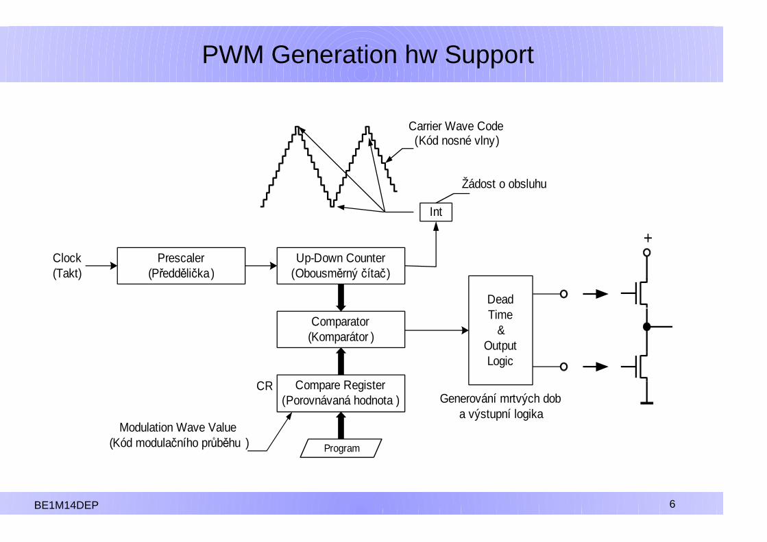
Prescaler(Předdělička)
Up-Down Counter(Obousměrný čítač)
Comparator(Komparátor )
Compare Register(Porovnávaná hodnota )
Program
DeadTime
&OutputLogic
Clock(Takt)
Int
Carrier Wave Code(Kód nosné vlny)
Modulation Wave Value(Kód modulačního průběhu )
Žádost o obsluhu
Generování mrtvých doba výstupní logika
PWM Generation hw Support
B1M14DEP 6BE1M14DEP 6

7
PWM Generation (One possible option)
B1M14DEP 7
+
Carrier Wave(Nosná vlna)
Modulation Wave(Modulační průběh)
Interrupt Request(Žádost o obsluhu)
PWM Output(Výstup PWM)
Time
+1
-1
0
PWM Output(Výstup PWM)
B1M14DEP 7BE1M14DEP 7
8
Vector Control
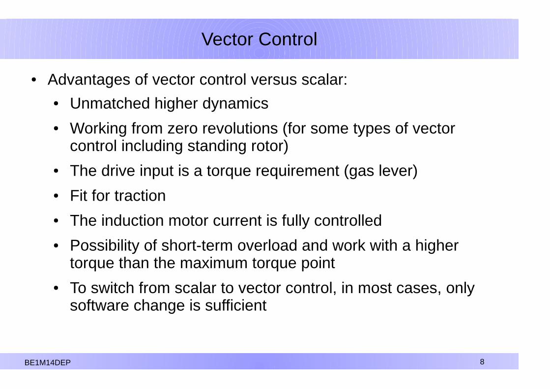
● Advantages of vector control versus scalar:● Unmatched higher dynamics● Working from zero revolutions (for some types of vector
control including standing rotor)● The drive input is a torque requirement (gas lever)● Fit for traction● The induction motor current is fully controlled● Possibility of short-term overload and work with a higher
torque than the maximum torque point● To switch from scalar to vector control, in most cases, only
software change is sufficient
B1M14DEP 8B1M14DEP 8B1M14DEP 8BE1M14DEP 8
9
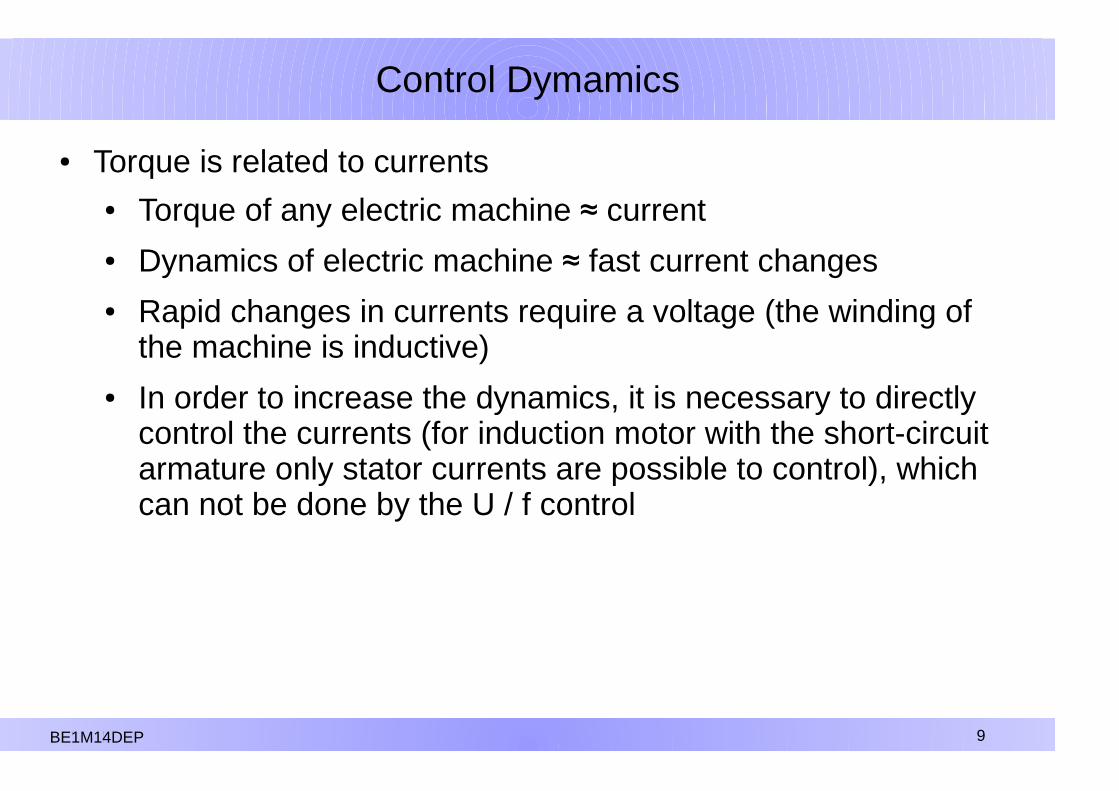
Control Dymamics
● Torque is related to currents● Torque of any electric machine ≈ current● Dynamics of electric machine ≈ fast current changes● Rapid changes in currents require a voltage (the winding of
the machine is inductive)● In order to increase the dynamics, it is necessary to directly
control the currents (for induction motor with the short-circuit armature only stator currents are possible to control), which can not be done by the U / f control
B1M14DEP 9B1M14DEP 9B1M14DEP 9BE1M14DEP 9

10
Vector Control
● Vector control:● Two quantities of the induction machine are controlled separately● Mostly, this is a stator current divided into two components:
– Current component affecting the magnetic flux– Current component affecting the torque
IMI1
IM
IM
IΨ→ =
B1M14DEP 10
DC machineIM machine
B1M14DEP 10B1M14DEP 10BE1M14DEP 10

11
Space Vector Idea
● The space vector can express the effect of all currents flowing through all phases of the electric machine stator
● Symmetrical winding is assumed for a three-phase, two-pole machine (the angle of rotation is 120 °)
● The expression can be modified provided the center point is not connected (i.e. i
a+i
b+i
c= 0) and after modifiying ej120° a ej240°
I 1
I=K i aib⋅ej⋅120 °i c⋅e
j⋅240 °
i =ℜ I =32⋅K⋅i a
I=K 32
i a j⋅32⋅i a2ib
i =ℑI =32⋅K⋅i b�i c=
32⋅K⋅i a2 i b
BE1M14DEP 11

12
Space Vector Idea
● The space vector can express the effect of all currents flowing through all phases of the electric machine stator
● Symmetrical winding is assumed for a three-phase, two-pole machine (the angle of rotation is 120 °)
● The expression can be modified provided the center point is not connected (i.e. i
a+i
b+i
c= 0) and after modifiying ej120° a ej240°
I 1
I=K i aib⋅ej⋅120 °i c⋅e
j⋅240 °
i =ℜ I =32⋅K⋅i a
I=K 32
i a j⋅32⋅i a2ib
i =ℑI =32⋅K⋅i b�i c=
32⋅K⋅i a2 i b
BE1M14DEP 12
Při vhodné volbě Kiα = ia

13
Clark Transformation
Clark's transformation converts the three phases (a, b, c) intotwo phases (α, β)For K = 2/3 Clark's transformation is expressed as:
ia
ibi
c
iα
iβ
Three phases of the machine →
→
Two axis
iα=i a iβ=√33⋅(i a+2 i b)
BE1M14DEP 13

14
Rotation of Coordinates
B1M14DEP 14
Space vector I in the coordinate system tied to the stator
Space vector I in coordinate system k
Where θk is the angle of rotation of the coordinate system k
I 1
I k
I k=
I 1⋅e
� j k
ik=iαcosθ
k+iβsinθ
ki l=�iαsinθk+iβcosθk
If the coordinate system (k, l) is rotated by the angle θk against (α, β):
BE1M14DEP 14

15
Park Transfomation
α
→
ω1
id=icosi sin
iq=�isini cos
θ
β
d
q
BE1M14DEP 15

16
Used Coordinate Systems
16BE1M14DEP 16
Coordinates Designation Rotationspeed
Coordinates tied to the stator α,β 0
Coordinates tied to the rotor k, l ω
Coordinates tied to the magnetic flux of the rotor d, q ω1

17
Induction Motor Torque
P=32∣U 1∣⋅∣I 1∣⋅cos=
32⋅ℜ U 1⋅
I 1∗Pro K=
23
BE1M14DEP 17

18
Induction Motor Torque
P=32∣U 1∣⋅∣I 1∣⋅cos=
32⋅ℜ U 1⋅
I 1∗For K=
23
U 1=R1⋅I 1
d 1
dt=R1⋅
I 1 j1 1
Voltage equation of induction motor stator windingwritten by space vectors:
BE1M14DEP 18
19
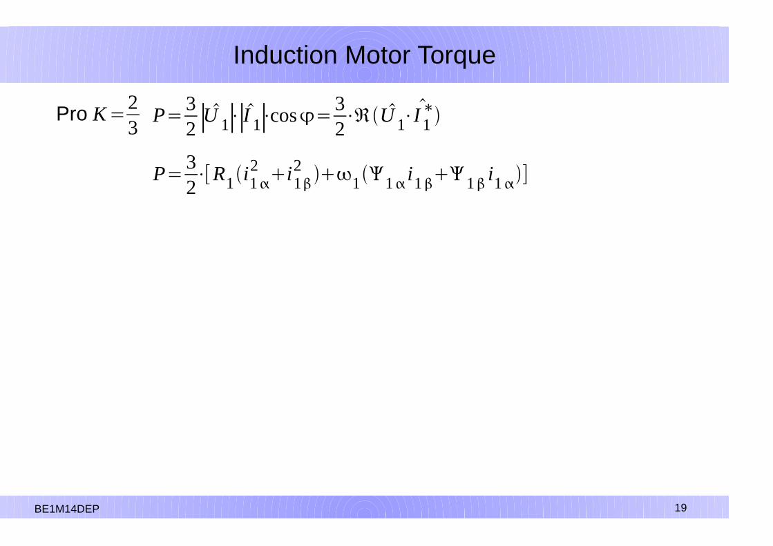
Induction Motor Torque
P=32∣U 1∣⋅∣I 1∣⋅cos=
32⋅ℜ U 1⋅
I 1∗Pro K=
23
P=32⋅[R1i1
2 i12 11 i11 i1]
BE1M14DEP 19
20
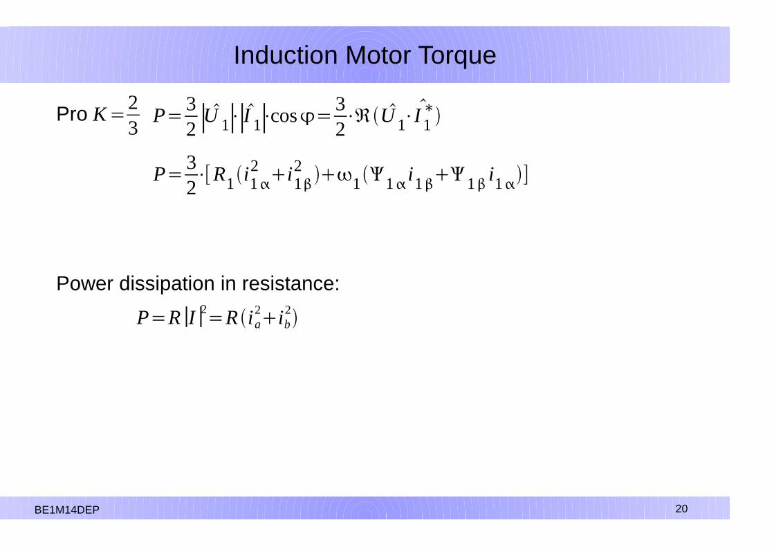
Induction Motor Torque
P=32∣U 1∣⋅∣I 1∣⋅cos=
32⋅ℜ U 1⋅
I 1∗Pro K=
23
P=32⋅[R1i1
2 i12 11 i11 i1]
Power dissipation in resistance:
P=R∣I∣2=Ri a2ib
2
BE1M14DEP 20

21
Induction Motor Torque
P=32∣U 1∣⋅∣I 1∣⋅cos=
32⋅ℜ U 1⋅
I 1∗Pro K=
23
P=32⋅[R1i1
2 i12 11 i11 i1]
Losses in the stator
P=R∣I∣2=Ri a2ib
2
BE1M14DEP 21

22
Induction Motor Torque
P=32∣U 1∣⋅∣I 1∣⋅cos=
32⋅ℜ U 1⋅
I 1∗Pro K=
23
P=32⋅[R1i1
2 i12 11 i11 i1]
Losses in the statorPower transmitted by
air gap from the stator to the rotor
BE1M14DEP 22

23
Induction Motor Torque
P=32∣U 1∣⋅∣I 1∣⋅cos=
32⋅ℜ U 1⋅
I 1∗Pro K=
23
BE1M14DEP 23
24
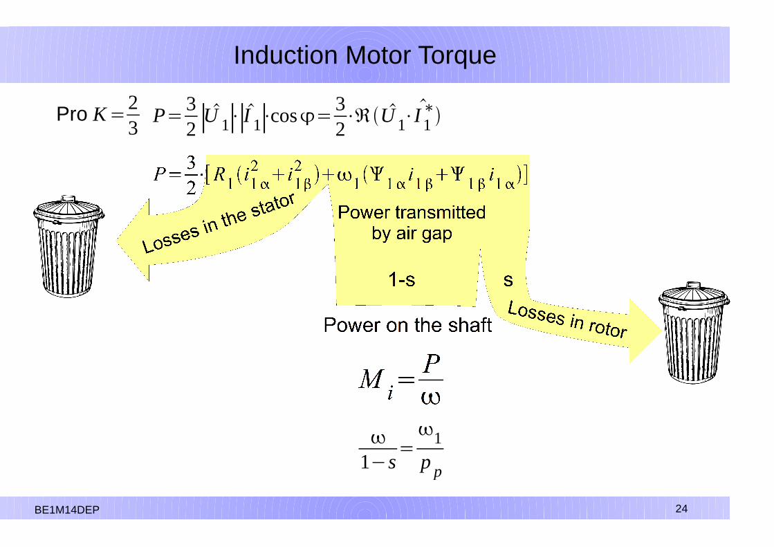
Induction Motor Torque
P=32∣U 1∣⋅∣I 1∣⋅cos=
32⋅ℜ U 1⋅
I 1∗Pro K=
23
1�s
=1
pp
BE1M14DEP 24

25
Induction Motor Torque
P=32∣U 1∣⋅∣I 1∣⋅cos=
32⋅ℜ U 1⋅
I 1∗Pro K=
23
BE1M14DEP 25
26
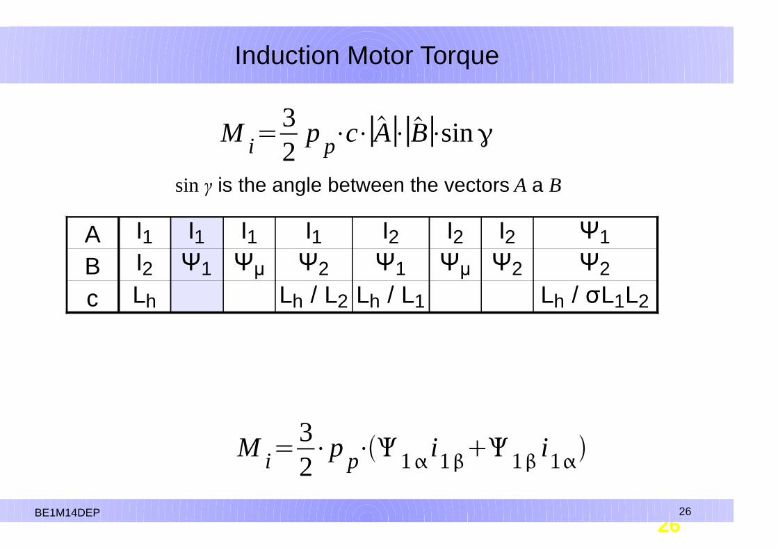
Induction Motor Torque
26BE1M14DEP 26
ABc
I1 I1 I1 I1 I2 I2 I2 Ψ1I2 Ψ1 Ψµ Ψ2 Ψ1 Ψµ Ψ2 Ψ2
Lh Lh / L2 Lh / L1 Lh / σL1L2
M i=32
pp⋅c⋅∣A∣⋅∣B∣⋅sin
sin γ is the angle between the vectors A a B
M i=32⋅pp⋅ 1 i1 1 i1

27
Induction Motor Torque
27BE1M14DEP 27
ABc
I1 I1 I1 I1 I2 I2 I2 Ψ1I2 Ψ1 Ψµ Ψ2 Ψ1 Ψµ Ψ2 Ψ2
Lh Lh / L2 Lh / L1 Lh / σL1L2
M i=32
pp⋅c⋅∣A∣⋅∣B∣⋅sin
sin γ is the angle between the vectors A a B
M i=32⋅pp⋅ 1 i1 1 i1
M i=32⋅pp⋅ 2d i1q 2q i1d ⋅
Lh
L2

28
Stator Current Components
M i=32⋅pp⋅ 2d i1q 2q i1d ⋅
Lh
L2
BE1M14DEP 28

29
Stator Current Components
BE1M14DEP 29
M i=32⋅pp⋅ 2d i1q 2q i1d ⋅
Lh
L2Ψ
2q is equal to zero because the (d, q) axis direction is given just
by the direction of Ψ2
M i=32⋅pp⋅ 2 i1q⋅
Lh
L2

30
Stator Current Components
BE1M14DEP 30
M i=32⋅pp⋅ 2d i1q 2q i1d ⋅
Lh
L2Ψ
2q is equal to zero because the (d, q) axis direction is given just
by the direction of Ψ2
M i=32⋅pp⋅ 2 i1q⋅
Lh
L2
M i≈i1q 2 i1q
stator current component
which affect the torque
Ψ2 is excitation

31
Stator Current Components
31BE1M14DEP 31
M i=32⋅pp⋅ 2d i1q 2q i1d ⋅
Lh
L2Ψ
2q is equal to zero because the (d, q) axis direction is given just
by the direction of Ψ2
M i=32⋅pp⋅ 2 i1q⋅
Lh
L2
M i≈i1q 2i1q
stator current component
which affects the torque
Ψ2 is excitation
d 2d
dt=
R2
L2Lh i1d�2d => 2 Lh i1d
i1d
stator current component
which affects magnetic flux

32
IM versus DC machine
BE1M14DEP 32
AM
i1q
i1d
ia
ib
i1q
≈ ia
i1d
≈ ib
The stator current of the three-phase induction short-circuit machinehas two stages of freedom (the third one is deleted because centerof windings is drawn outside) and can be divided into two componentsthat correspond to the armature current and the excitation of the DC motor.It is therefore possible to control independetly the torque and the excitationof induction machine.
DC machineIM machine
33
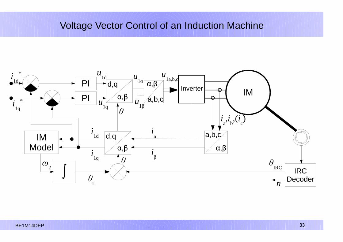
Voltage Vector Control of an Induction Machine
IMInverterPI
PI
IRCDecodern
θIRC
α,β
a,b,c
α,β
d,qIMModel
θr
α,β
d,q
θ
i1d
*
i1q
*
α,β
a,b,c
i1d
i1q
ia,i
b,(i
c)
iα
iβ
θ
u1d
u1q
u1α
u1β
u1a,b,c
∫ω
2
BE1M14DEP 33

34
Voltage Vector Control of an Induction Machine
34
IMInverterPI
PI
IRCDecodern
θIRC
α,β
a,b,c
α,β
d,qIMModel
θr
α,β
d,q
θ
i1d
*
i1q
*
α,β
a,b,c
i1d
i1q
ia,i
b,(i
c)
iα
iβ
θ
u1d
u1q
u1α
u1β
u1a,b,c
∫ω
2
Clark Transformation
i=i a i =33⋅i a2 i b
BE1M14DEP 34

35
Voltage Vector Control of an Induction Machine
35
AMstřídačPI
PI
IRCDecodern
θIRC
α,β
a,b,c
α,β
d,qIMModel
θr
α,β
d,q
θ
i1d
*
i1q
*
α,β
a,b,c
i1d
i1q
ia,i
b,(i
c)
iα
iβ
θ
u1d
u1q
u1α
u1β
u1a,b,c
∫ω
2
Park Transformation
id=i cosi sin
iq=�isini cos
BE1M14DEP 35

36
Voltage Vector Control of an Induction Machine
AMstřídačPI
PI
IRCDecodern
θIRC
α,β
a,b,c
α,β
d,qIMModel
θr
α,β
d,q
θ
i1d
*
i1q
*
α,β
a,b,c
i1d
i1q
ia,i
b,(i
c)
iα
iβ
θ
u1d
u1q
u1α
u1β
u1a,b,c
∫ω
2
Induction machine I1-n model
dΨ2
dt=
R2
L2(Lhi1d�Ψ2) ω2=
Lh R2
L2
i1qΨ2
B1M14DEP 36

37
Voltage Vector Control of an Induction Machine
AMstřídačPI
PI
IRCDecodern
θIRC
α,β
a,b,c
α,β
d,qIMModel
θr
α,β
d,q
θ
i1d
*
i1q
*
α,β
a,b,c
i1d
i1q
ia,i
b,(i
c)
iα
iβ
θ
u1d
u1q
u1α
u1β
u1a,b,c
∫ω
2
Induction machine I1-n model
d 2
dt=
R2
L2Lhi1d� 2 2=
Lh R2
L2
i1q
2
BE1M14DEP 37

38
Voltage Vector Control of an Induction Machine
AMstřídačPI
PI
IRCDecodern
θIRC
α,β
a,b,c
α,β
d,qIMModel
θr
α,β
d,q
θ
i1d
*
i1q
*
α,β
a,b,c
i1d
i1q
ia,i
b,(i
c)
iα
iβ
θ
u1d
u1q
u1α
u1β
u1a,b,c
∫ω
2
Induction machine I1-n model after
suitable substitution is used i 2= 2
Lhd i 2
dt=
R2
L2i1d�i 2 2=
R2
L2⋅
i1q
i 2
BE1M14DEP 38
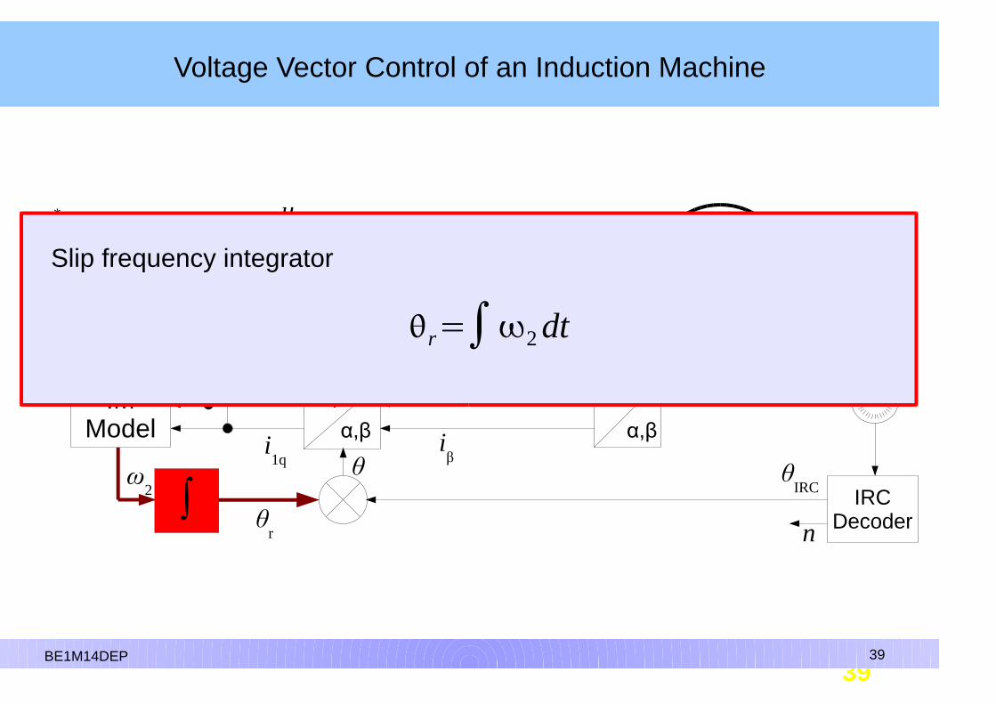
39
Voltage Vector Control of an Induction Machine
39
AMstřídačPI
PI
IRCDecodern
θIRC
α,β
a,b,c
α,β
d,qIMModel
θr
α,β
d,q
θ
i1d
*
i1q
*
α,β
a,b,c
i1d
i1q
ia,i
b,(i
c)
iα
iβ
θ
u1d
u1q
u1α
u1β
u1a,b,c
α,β
∫ω
2
Slip frequency integrator
r=∫2 dt
BE1M14DEP 39

40
Voltage Vector Control of an Induction Machine
40
IMstřídačPI
PI
IRCDecodern
θIRC
α,β
a,b,c
α,β
d,qIMModel
θr
α,β
d,q
θ
i1d
*
i1q
*
α,β
a,b,c
i1d
i1q
ia,i
b,(i
c)
iα
iβ
θ
u1d
u1q
u1α
u1β
u1a,b,c
α,β
∫ω
2
The IRC sensor decoder
BE1M14DEP 40
θ IRC=number of pulsespulses per rotation
⋅pp
2
41
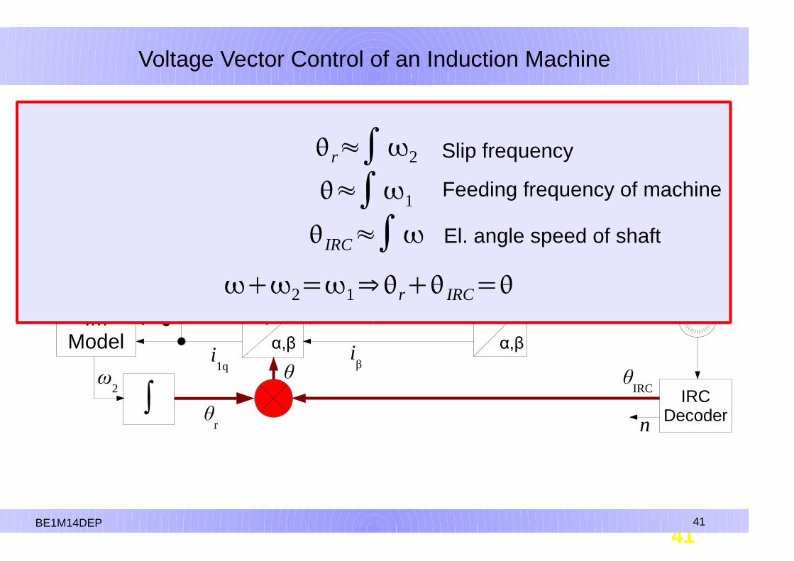
Voltage Vector Control of an Induction Machine
41
AMstřídačPI
PI
IRCDecodern
θIRC
α,β
a,b,c
α,β
d,qIMModel
θr
α,β
d,q
θ
i1d
*
i1q
*
α,β
a,b,c
i1d
i1q
ia,i
b,(i
c)
iα
iβ
θ
u1d
u1q
u1α
u1β
u1a,b,c
α,β
∫ω
2
BE1M14DEP 41
r≈∫2
≈∫1
IRC≈∫
Slip frequency
Feeding frequency of machine
El. angle speed of shaft
2=1⇒r IRC=

42
Voltage Vector Control of an Induction Machine
42
IMInverterPI
PI α,β
d,q
θ
i1d
*
i1q
*
α,β
a,b,c
i1d
ia,i
b,(i
c)
iα
u1d
u1q
u1α
u1β
u1a,b,c
ut =k pet ∫k i et dt
BE1M14DEP 42
dekodérIRCn
θIRC
α,βa,b,c
α,β
d,qIMModel
θr
i1q
iβ
θ
∫ω
2
PI controllers regulate each component of the current separatelyBoth components are DC (does not change with ω, ω
1 or ω
2)
The input to the controllers are the error values of the currents.The outputs are a voltage requirements.
ut =k pet ∫k i et dt
43
Voltage Vector Control of an Induction Machine
IMInverterPI
PI α,β
d,qi1d
*
i1q
*
α,β
a,b,c
u1d
u1q
u1α
u1β
u1a,b,c
B1M14DEP 43
dekodérIRCn
θIRC
α,β
a,b,c
α,β
d,qmodelAM
θr
i1d
i1q
ia,i
b,(i
c)
iα
iβ
θ
α,β
∫ω
2
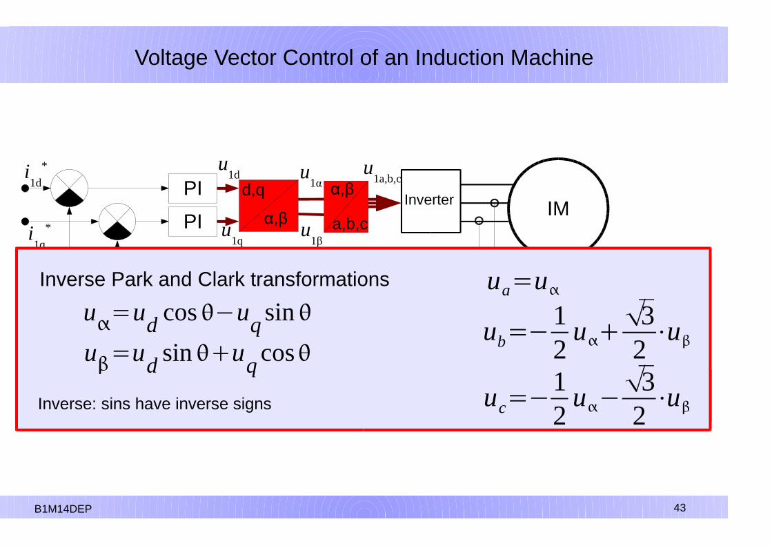
Inverse Park and Clark transformations
u=ud cos�uqsin
u=ud sinuqcos
Inverse: sins have inverse signs
ua=u
ub=�12
u32⋅u
uc=�12
u�32⋅u

44
Voltage Vector Control of an Induction Machine
BE1M14DEP 44
45
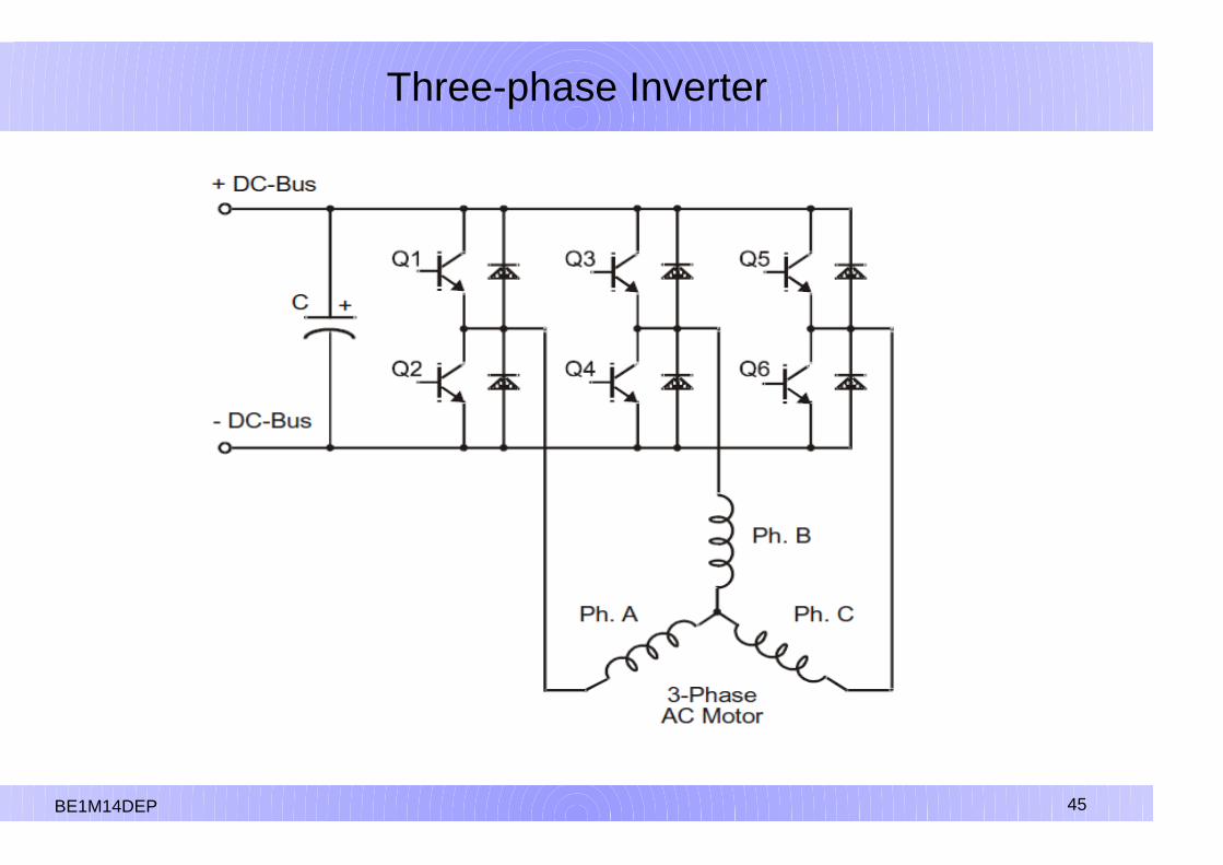
Three-phase Inverter
BE1M14DEP 45

46
Space Vector Modulation
Each of the three branches of the voltage converter always has only one of two transistor switched on. For the three branches it is 23 = 8 different states altogether.
a b c Ua-b Ub-c Ua-c výstup
0 0 0 0 0 0 nic
1 0 0 +UDC
0 -UDC
0°
1 1 0 0 +UDC
-UDC
60°
0 1 0 -UDC
+UDC
0 120°
0 1 1 -UDC
0 +UDC
180°
0 0 1 0 -UDC
+UDC
240°
1 0 1 +UDC
-UDC
0 300°
1 1 1 0 0 0 nic
BE1M14DEP 46

47
Space Vector Modulation
BE1M14DEP 47

48
Space Vector Modulation
BE1M14DEP 48

49
Space Vector Modulation
Six available active statesat the output of the inverter
BE1M14DEP 49
a
b
c
U0
U60U120
U180
U240 U300

50
Space Vector Modulation
To achieve a certain outputshould be combined over timeseveral output vectors,including zero vector.There are many ways,how to draw a vectorwhich differ in accuracy,computational difficultyand switching losses.However, the outputs alwayshave character PWM modulation.
The simplest method is:
PWMx=ux
2Umax
0.5
x∈{a ,b ,c}
BE1M14DEP 50
a
b
c
U0
U60

51
Space Vector Modulation
BE1M14DEP 51

52BE1M14DEP 52
Space Vector Modulation

53
Digital Control of Electric Drives
Induction Motor Vector Control
End
BE1M14DEP 53