


Languages
Pages
Legal

BowTie Range Design GuideIncludes use as a wall-diaphragm anchorage
in seismic upgrades

2
The BowTie range 3
Applications 4
BowTie Installation and Technical Specification 5
BowTie HD Installation and Technical Specification 6
Specification & Testing 7
Design Guidance 8
Design Example 11
Contents

3
The BowTie range
The BowTie HD is a larger tie and
comprises a more conventional threaded
profile. The tie is manufactured from
stainless steel, grade 304 as standard.
The thread is produced by cold rolling a
9mm (3/8”) round bar to leave a
threaded rod of nominal 12mm (1/2”)
diameter. It has a self-cutting tip at one
end and a short section of a reduced
diameter at the other to allow a fitting
tool to be connected for installation. The
intended use is tying masonry to joist
sides. Installation involves drilling a
clearance hole through the masonry
before driving the BowTie HD through
the first and subsequent joists, using a
setting tool fitted to a drill set on rotary
only, to create a mechanical connection
within the wood. HeliBond grout is used
to bond the outer end of the tie to the
masonry. A concealed installation is
achieved by patching the entry hole with
appropriate matching materials.
The Helifix BowTie connects masonry
walls to internal wood floor or ceiling
joists.There are two types of BowTie, the
standard BowTie and the BowTie HD.
The standard BowTie is a helically
shaped tie manufactured from stainless
steel, grade 316, as standard. This tie is
used when tying masonry to joist ends.
Ties are available in two standard
diameters, 8mm (5/16”) and 10mm
(3/8”), and in a variety of different lengths.
Installation requires the use of an electric
hammer drill and setting tool to drive
one end of the tie into the end of the
wood joist to produce a mechanical
connection. Access to the joist is
achieved by first drilling a small clearance
hole through the masonry. HeliBond
grout is used to bond the tail of the tie
to the masonry. A concealed installation
is achieved by patching the entry hole
with appropriate matching materials.
HeliBond, a high performance, injectable, non-shrink,
cementitious grout, is used to bond BowTies to
masonry. Refer to the HeliBond technical datasheet
for full details, available online.

4
Applications
BowTie HD• BowTie HDs are recommended when
installing into joist sides
• Quick, easy, non-disruptive external
installation
• Self-tapping design – no splitting of
timbers
• Effective in all common wall materials
• Suitable for hardwood use
• Easily tested for security of connection
• Fully concealed – no unsightly
external plates
• For stabilizing bowed external
building walls
• For seismic upgrades
BowTie HD into parallel joists through a solid wall
BowTie HD installedthrough blocker fittedbetween parallel joists
BowTie into joist endthrough a solid wall
BowTie HDs into roof space joists through a solid wall. Additional wood blockingand plywood overlay may be required to create the necessary diaphragm action
BowTies are used to stabilize or
reinforce building walls by securing
the masonry to the wood joists of
the internal floor and roof
diaphragms. They are installed
externally and provide a rapid, reliable
and economical solution that is fully
concealed as no unsightly external
plates are required.
BowTie• Standard helical BowTies are
recommended when installing into
joist ends
5
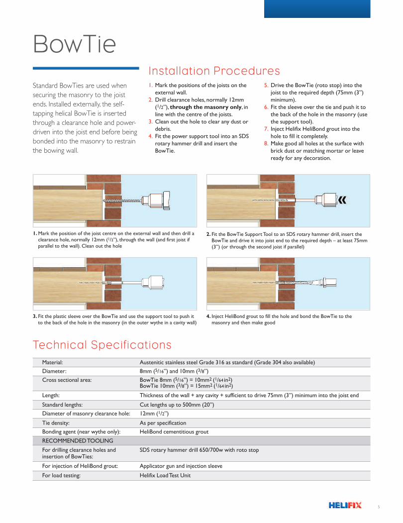
BowTieInstallation Procedures1. Mark the positions of the joists on the
external wall.
2. Drill clearance holes, normally 12mm
(1/2”), through the masonry only, in
line with the centre of the joists.
3. Clean out the hole to clear any dust or
debris.
4. Fit the power support tool into an SDS
rotary hammer drill and insert the
BowTie.
5. Drive the BowTie (roto stop) into the
joist to the required depth (75mm (3”)
minimum).
6. Fit the sleeve over the tie and push it to
the back of the hole in the masonry (use
the support tool).
7. Inject Helifix HeliBond grout into the
hole to fill it completely.
8. Make good all holes at the surface with
brick dust or matching mortar or leave
ready for any decoration.
1. mark the position of the joist centre on the external wall and then drill aclearance hole, normally 12mm (1/2”), through the wall (and first joist ifparallel to the wall). clean out the hole
2. Fit the BowTie Support Tool to an SDS rotary hammer drill, insert theBowTie and drive it into joist end to the required depth – at least 75mm(3”) (or through the second joist if parallel)
3. Fit the plastic sleeve over the BowTie and use the support tool to push itto the back of the hole in the masonry (in the outer wythe in a cavity wall)
4. Inject HeliBond grout to fill the hole and bond the BowTie to themasonry and then make good
Technical Specif ications
Material: Austenitic stainless steel Grade 316 as standard (Grade 304 also available)
Diameter: 8mm (5/16”) and 10mm (3/8”)
Cross sectional area: BowTie 8mm (5/16”) = 10mm2 (1/64 in2)BowTie 10mm (3/8”) = 15mm2 (1/64 in2)
Length: Thickness of the wall + any cavity + sufficient to drive 75mm (3”) minimum into the joist end
Standard lengths: Cut lengths up to 500mm (20”)
Diameter of masonry clearance hole: 12mm (1/2”)
Tie density: As per specification
Bonding agent (near wythe only): HeliBond cementitious grout
REcommEnDED ToolInG
For drilling clearance holes and SDS rotary hammer drill 650/700w with roto stopinsertion of BowTies:
For injection of HeliBond grout: Applicator gun and injection sleeve
For load testing: Helifix Load Test Unit
Standard BowTies are used when
securing the masonry to the joist
ends. Installed externally, the self-
tapping helical BowTie is inserted
through a clearance hole and power-
driven into the joist end before being
bonded into the masonry to restrain
the bowing wall.

6
1. mark the position of the joist centre on the external wall and then drill aclearance hole, normally 16mm (5/8”), through the wall. clean out the hole
2. Fit the BowTie HD Support Tool to an SDS rotary hammer drill, insertthe BowTie HD and drive it (off hammer) into, and through, the first andsecond joists
4. Fit the plastic sleeve over the BowTie HD and use the support tool topush it to the back of the hole in the wall (outer wythe in a cavity wall)
3. Test security of anchors in the joists
5. Inject HeliBond grout to fill the hole and bond the BowTie HD to themasonry and then make good
Technical Specif icationsMaterial: Austenitic stainless steel Grade 304 (1.4301)
Diameter: 12mm (1/2”)
Cross sectional area: 63mm2 (3/32in2)
Length: Thickness of the wall + any cavity + sufficient to drive into the second parallel joist(or third where specified)
Standard lengths: 1m and 1.5m (40” and 60”) – in packs of 5
Diameter of masonry clearance hole: 16mm (5/8”)
Tie density: As per specification. Refer to specification and testing information on page 7
Bonding agent (near wythe only): HeliBond cementitious grout
REcommEnDED ToolInG
For drilling clearance holes and SDS rotary hammer drill 650/700w with hammer-stopinsertion of BowTie HDs:
For installation of BowTie HDs: BowTie HD driver
For injection of HeliBond grout: Applicator gun
BowTie HD
The heavy duty BowTie HD is a
12mm (1/2”) diameter threaded bar
with a self-cutting end used to secure
the wall masonry to two or three
parallel joists. Installed externally for
minimum inconvenience, the BowTie
HD is inserted through a clearance
hole and then driven into the first
and subsequent joists before being
bonded into the masonry.
Installation Procedures1. Mark the positions of the joists on the
external wall.
2. Drill clearance holes, normally 16mm
(5/8”), through the masonry only, in
line with the centre of the joists.
3. Clean out the hole to clear any dust or
debris.
4. Fit the power support tool into an SDS
rotary hammer drill and insert the
BowTie HD.
5. Install the BowTie HD (with hammer off)
into and through the first and second
joists (and third joist, if specified). When
the BowTie HD is between joists,
proceed slowly and take care to avoid
‘whip’.
6. Fit the sleeve over the tie and push it to
the back of the hole in the masonry with
the BowTie Injection Tube.
7. Inject Helifix HeliBond grout into the
hole to fill it completely.
8. Make good all holes at the surface with
brick dust or matching mortar or leave
ready for any decoration.

7
BowTie type Minimum penetration Minimum penetration Condition of joist Recommended maximum when installed into when installed into achievable anchorage joist end joist side capacity (kN)***
10mm (3/8”) standard 60mm (21/2”) – Good* 2.0
10mm (3/8”) standard 80mm (31/8”) – Good* 3.0
10mm (3/8”) standard 100mm (4”) – Good* 4.0
10mm (3/8”) standard 120mm (43/4”) – Good* 4.5
12mm (1/2”) HD – 100mm (4”) Good* 9.0
12mm (1/2”) HD – 100mm (4”) Excellent** 17.0
12mm (1/2”) HD – 150mm (57/8”) Excellent** 17.0
Table 1. maximum achievable BowTie anchorage capacities in wood (Ismail 2014)
Specification & Testing
BowTie specifications must take into
account the engineering objectives and
the physical characteristics and condition
of the masonry and wood into which ties
are to be installed. Anchorage capacities
are dependent on these physical factors
and can be expected to vary from
building to building. On-site tension
testing may be undertaken to confirm
achievable loads. Guidance may be
sought from results of independent
testing listed below (Ismail 2014).
BowTie has been tested in New Zealand
using local materials to establish the
seismic performance of the system as a
wall-diaphragm anchorage. The test
programme included laboratory and
on-site testing into original hardwood
(Rimu), new build wood (H3 treated
pine), and historic clay brick masonry.
Characteristic maximum values are
presented in Tables 1 and 2.
Achievable anchorage capacities will
depend on the physical condition of the
wood and masonry present at site.
Thus appropriate care should be
exercised when using these values and
appropriate strength reduction factors
applied when designing wall-diaphragm
anchorages.
* Hard wood such as Rimu that has no signs of excessive moisture or rot, with borer less than 5% of the total surface area.
** Machine graded new H3 joists. *** Achievable loads should be tested on site.
BowTie type Minimum effective Minimum thickness Min URM* sliding Maximum achievable embedment of the wall shear strength (kPa) anchorage capacity (kN)**
8mm (5/16”)or 70mm (23/4”) – – 3 to 510mm (3/8”) standard to 210mm (81/4”)
12mm (1/2”) HD 210mm (81/4”) 220mm (85/8”) 150 11
12mm (1/2”) HD 310mm (121/4”) 330mm (13”) 150 13.5
Table 2. maximum achievable BowTie anchorage capacities resin-fixed into masonry (Ismail 2014)
* Unreinforced masonry must be free from any apparent cracking/damage, and anchors installed in bricks not mortar beds.
** Achievable loads should be tested on site.

8
The first step in the design of a parapet
restraint is to establish the design lateral
seismic forces. A linear static analysis
procedure, the Equivalent Static Lateral
Force Method, is normally performed for
assessing strength demands on an out-of-
plane URM parapet wall when subjected to
a design level earthquake. Although URM
response is highly inelastic and nonlinear, the
outlined detailed linear static method
provides a reasonable estimate of the
seismic demands. The procedure
reproduced herein was adapted by Ismail
(2014) from NZS1170.5 loading standards
(2004) and NZSEE guidelines (2006) for
the assessment of out of-plane URM walls.
Figure 1 shows the flow chart for the
calculation of seismic demands on the
anchorage.
Design out-of-plane lateral force for URM
walls can be calculated in accordance using
NZS 1170.5 (2004) defined spectra for
parts and portions (refer Equation 1),
where Cp(Tp) is the horizontal acceleration
coefficient; γ is the modal participation
factor for the rocking system; Rp is the part
risk factor and is taken as 1; and Ww is the
weight of the wall tributary area.
EqUATION 1
Vo* = cp(Tp)γRpWw
Design Guidance†
Notationbw Wall thickness (m)
C(0) Site hazard coefficient for
Tp = 0 sec (fraction of g)
CHi Floor acceleration coefficient for
level i (constant)
Ci(Tp) Part spectral shape factor at level i
(constant)
Cp(Tp) Horizontal acceleration coefficient
(fraction of g)
g Acceleration due to gravity (m/sec2)
he Wall height (N)
hi Height of the hinge location (m)
hn Total height of the structure (m)
N(0,D) Near-fault factor (constant)
Nt Axial load due to upper storeys (N)
R Return period factor (constant)
Rp Part risk factor (constant)
Tp Natural period of the wall (sec)
Vo* Design out-of-plane lateral force (N)
Ww Self weight of the wall (N)
Z Seismic hazard factor (constant)
γ Modal participation factor
(constant)
Step 1Calculate seismic demand (Vo*)
Calculate self weight of the twosegments of the parapet
Calculate horizontal accelerationcoefficient, Cp(Tp) and Cp(0.4)
Calculate modal participation factor
Calculate design lateral force, Vo*
Establish part risk factor, Rp inaccordance with NZS 1170.5:2004
Calculate design uniform pressure,vo*, and then force per anchorageby multiplying the design pressure
with the tributary area of eachwall-diaphragm anchor
i.e. vo* = Vo*/bwhe
Calculate period and find partspectral shape factor, Ci(Tp)
Find the maximum partspectral shape factor, Ci(0.4)
Calculate floor accelerationcoefficient, CHiCalculate C(0)
Establish hi, hn and he for bothsegments of the parapet
Establish factors Z, R, N(0, D) andCh(0) for site location and subsoilcharacteristics in accordance with
NZS 1170.5:2004
Figure 1 Flowchart of steps involved incalculating out-of-plane loads on URmwalls that would need to be resisted bythe wall-diaphragm anchorage
† Extract from Ismail (2014).
Solid Ground Ltd, Otago, NZ

9
For loads on out-of-plane URM walls
supported by flexible diaphragms, a design
horizontal acceleration coefficient for the
level of structure that supports the wall,
Cp(Tp), is calculated using Equation 2.
Where C(0) is the site hazard coefficient for
Tp = 0 sec and is calculated in accordance
with values suggested by NZS 1170.5
(2004) as given by Equation 3; CHi is the
floor acceleration coefficient for level i; and
Ci(Tp) is the part spectral shape factor at
level i.
EqUATION 2
cp(Tp) = c(0)cHici(Tp)
EqUATION 3
c(0) = ch(0)ZRn(0,D)
Where Ch(0) is the spectral shape factor
for Tp = 0 sec, values for different soil type
profiles; Z is the seismic hazard factor and
must be determined in accordance with
Section 3.1.4 of NZS 1170.5 (2004); R is the
return period factor and must be
determined in accordance with Section
3.1.5 of NZS 1170.5 (2004) but limited
such that ZR does not exceed 0.7; N(0,D) is
the near-fault factor and must be
determined in accordance with Section
3.1.6 of NZS 1170.5 (2004).
The floor acceleration coefficient, CHi, is
calculated using either of Equations 4 to 6
as appropriate for the floor height, hi, and if
two height limitations are satisfied then the
smaller of the two is used. In Equations 4 to
6, hi is the floor height supporting the out-
of-plane loaded URM walls and hn is the
total height of the structure. The part
spectral shape factor, Ci(Tp), is calculated
using Equation 7, where Tp is the natural
period of the URM wall.
EqUATION 4
cHi = 1 + hi
6
EqUATION 5
cHi = 1 + 10 hihn
EqUATION 6
cHi = 3
EqUATION 7
ci (Tp) = 2(1.75 –Tp)
for all hi < 12 m
for hi < 0.2 hn
for hi ≥ 0.2 hn
and 0.5 < ci(Tp) < 2.0
Wwhegγ =
8[0.083Ww(he + 16bw) + 2.25ntbw]
1.5γ =
1 +bw
he
Tp = 0.67he
1 + 2nt
Ww
[ ]
[ ]
EqUATION 10
EqUATION 11
][
( )
Tp = 2.67 1 +bw
2
he
The natural period for a URM wall is
established by solving the equation of
motion for free vibration. Typically, URM
walls can either have one way bending
deformation mode when supported
between two adjacent diaphragms or
perform as cantilever when supported at
the base only. Based on the location of
hinges and the boundary conditions,
equations of motion for free vibration/
rocking were solved and Equations 8 and 9
were established for continuous and
cantilever boundary conditions respectively.
EqUATION 8
EqUATION 9
Where Ww is the self-weight of the wall, Ntis the axial load due to upper storeys, bw is
wall thickness, g is accelerations due to
gravity and has a value of 9.81 m/sec2, and
he is the wall height.
For a laterally braced URM parapet wall, the
portion of parapet above bracing support
acts as cantilever wall and the parapet
portion between the bracing support and
roof anchorage acts as face loaded two-way
URM wall. Accordingly, the wall-bracing
anchorages are designed for a lateral force
based on the tributary area for the bracing
support and the calculated uniform seismic
lateral force. Figure 2 shows the deflected
shape of an out-of-plane loaded wall.
It must be noted that if wall-diaphragm
anchorage is insufficient at each floor
level then the wall would behave as a
cantilever over the full height, resulting in
an extremely small out-of-plane strength.
Where Ww is the self-weight of the wall, Nt
is the axial load due to upper storeys, bw is
the wall thickness and he is the wall height.
However, for anchorage design a maximum
horizontal acceleration coefficient Cp(0.4) of
Tp = 0.4 sec may be used in the calculation
of design out-of-plane lateral forces. Likewise
for out-of-plane loaded walls having an
aspect ratio of more than 10 and a small
overburden weight, a maximum modal
participation factor of 1.5 can be used.
However, for squat walls with large
overburden weights, a modal participation
factor for the rocking system is calculated
using Equation 10 and 11 for continuous and
cantilever boundary conditions respectively.
(( )[ ]
2 2 2
2
can
tile
ver
onew
ay b
endin
g
Figure 2 Deflected shapes of a properly securedURm wall when subjected to out-of-plane seismicforces

10
Based on the testing results, it can be
inferred that the tension capacity of a
Helifix BowTie HD, when installed as a
wall-diaphragm anchorage, is governed by
either steel yielding, or a tensile breakout of
masonry/wood, whichever is smaller. Steel
yielding has been well studied and
documented in building standards
(MSJC 2005; ICC 2010) and can be
estimated by using Equation 12.
EqUATION 12
øBan = øAb 0.75fu
and for ø=0.9, øBan = 0.68Abfu
Where: ø = strength reduction factor and
has a recommended value of 0.9 (MSJC
2005); Ab = is the effective cross sectional
area of the BowTie HD and fu = ultimate
tensile strength of BowTie HD (typical value
for ASTM 304 stainless steel fu = 520 MPa).
This results in a maximum dependable
tension capacity for one 12mm (1/2”) BowTie
HD of 11.34 kN. Whereas the tensile
breakout capacity of masonry is given by
Equation 13 in MSJC standards (MSJC 2005).
EqUATION 13
øBan = 0.332 øApt (fm)1/2
Where: Apt = projected area on masonry
surface of a right circular cone that can be
calculated as πlb2 where lb is the effective
embedment length of the BowTie HD; and
fm = masonry compression strength. The
MSJC standards (MSJC 2005) recommends
a ø value of 0.5 for masonry breakout. After
substituting the value of strength reduction
factor and based on recent comprehensive
New Zealand based research on URM
materials (Lumantarna 2012) it is deemed
that use of masonry flexural bond strength
(ffb) is more appropriate measure of
masonry tensile breakout. Therefore,
Equation 14 is recommended herein for
calculating the anchorage capacity of BowTie
HD when installed in New Zealand old
URM:
EqUATION 14
øBan = 0.5AptffbIt is noted here that ffb can be determined
ASTm (1996). ASTM E488-96: Standard test
methods for strength of anchors in concrete and
masonry elements. West Conshohoken, USA,
American Society for Testing and Materials
International.
Icc (2010). California existing building code.
Country Club Hills, US, International Code Council.
Ismail n. (2014). Seismic improvement of wall-
diaphragm anchorage using Helifix BowTie and
BowTie HD. Dunedin, Solid Ground Limited.
lumantarna, R. (2012). Characterisation of materials
in URM buildings in New Zealand. Department of
Civil and Environmental Engineering. Auckland, New
Zealand, University of Auckland. Ph.D.
mSJc (2005). ACI 530-05/ASCE 5-05/TMS 402-05:
Building code requirements for masonry structures.
Boulder, CO, USA, The Masonry Society.
nZSEE (2006). Assessment and improvement of the
structural performance of buildings in earthquakes:
recommendations of a NZSEE study group on
earthquake risk buildings. Wellington, NZ, New
Zealand Society for Earthquake Engineering.
nZSEE (2011). Assessment and improvement of
unreinforced masonry buildings for earthquake
resistance. Wellington, New Zealand Society for
Earthquake Engineering.
more accurately by undertaking onsite
testing. Typical value of ffb for pre-1930
URM buildings ranges from 0.1 – 0.4 MPa.
The shear strength of the Helifix BowTie HD
can similarly be calculated using the
Equations 15 and 16, corresponding to
strength of the system associated to tie
failure and masonry failure, respectively.
EqUATION 15
øBvn = 0.5Abfu
EqUATION 16
øBvn = 0.5Apvffb
Where: Ab = is the effective cross sectional
area of the BowTie HD; fy = tensile yield
strength of BowTie HD stainless steel
(typical value for ASTM 304 stainless steel fy= 200 MPa); Apv = projected area on
masonry surface of one-half of a right
circular cone that can be calculated as
0.5πlbe2 where lbe is the smaller of edge
distance or effective embedment length of
the BowTie HD; and fm = masonry
compression strength.
The withdrawal strength of a BowTie HD
can be estimated by considering mechanical
action between wood and tie bar. Equation
17 is a simplified, empirical equation
developed with the experimental results
and may be used to estimate the anchorage
capacity of Helifix BowTie HD when
installed in wood joists.
However, it is noted here that the bending
strength of joists, strength of associated
hardware, load path continuity, and
diaphragm strengths be checked using
NZS3603: Wood Structures Standards to
allow transfer of additional lateral force
transferred from BowTie HD to diaphragm
joists.
EqUATION 17
ø Btn = ølbfctWhere: ø Btn = the nominal tensile
Step 2Calculate capacity of one wall-diaphragm anchor (Bn)
References
anchorage capacity of BowTie HD; ø =
strength reduction factor, 0.9 recommended
for new Raidata Pine wood joists and 0.5 for
old wood joists of existing URM buildings; lb= effective embedment length of BowTie
HD; and fct = bearing strength per mm
embedment of BowTie HD in wood i.e. 170
N/mm. Note that the effect of age of wood
joists has been accounted for in the
recommended strength reduction factors.

11
Let us say we have calculated uniform
lateral pressure on a URM wall using
NZS1170.5 parts and portions spectra and
it is:
vo* = 3.89 kN/m2
If BowTie HD is installed every X m centre
to centre spacing then we get a demand on
each BowTie HD by calculating the
tributary area.
Bu = X × 3.300 × 3.89 = 12.84X kN
Step 1Demand onwall-diaphragmanchorage Bu
Step 3Required spacing of the BowTie HD
For the URM wall data, found from investigation, given in Table 1 we can then estimate
capacity of a Helifix BowTie HD.
Where: he = effective height of URM wall between two adjacent lines of wall-diaphragm
anchors; bw = nominal thickness of URM wall; tj = width of diaphragm joists; ffb = masonry
flexural bond strength; dj = depth of diaphragm joists; and sj = spacing of diaphragm joists.
It is also found that the diaphragm has sufficient sub-diaphragm action to transfer the total
anticipated lateral force to the rest of diaphragm.
i: Tensile strength of BowTie HD with Ab = 60 mm2 and fu = 520 MPa
ø Ban = 0.68Abfuø Ban = 0.68 × 60 × 520 = 21,216 N or 21.21 kN
ii: Masonry tensile breakout strength for 12 mm BowTie HD and HeliBond
standard installation
ø Ban = 0.5 Aptffb where Apt = πlb2
For a typical BowTie HD installed from exterior face of the wall, lb = bw
Apt = 3.1415 ×(210)2 = 138540.15 mm2
ø Ban = 0.5 × 138540.15 × 0.18
ø Ban = 12.47 kN
iii: Bearing strength of BowTie HD in Wood joists
ø Btn = ø lbfctø = 0.5 (for installation in damage free good condition existing Rimu joists)
fct = 170 N/mm (recommended for BowTie HD based on experimental investigations)
lb = 100 mm (when installed from side of two 50 mm (2”) wide joists)
ø Btn = 0.5 × 100 × 0.17
ø Btn = 8.5 kN
Nominal anchorage capacity of BowTie HD = 8.5 kN
8.5 kN = 12.84X kN
X = 0.66199 m or say round to nearest 50 mm (2”) or 100 mm (4”)
The recommended spacing then can be 600 mm (235/8”) o.c.
Step 2Capacity of wall-diaphragm anchorage
Design Example
Parameter he bw tj dj ffb sj Joist notes m mm mm MPa MPa mm
GoodValue 10 210 39.4 1.4 0.18 0.09
condition Rimu

Helifix
8521 FM 1976
PO Box 547 Converse
TX 78109
USA
Tel: 888-992-9989
email: [email protected]
www.helifix.com
Top Related