


Languages
Pages
Legal

INCH-POUND MIL-PRF-83536A 21 March 1997
SUPERSEDINGMIL-R-8353622 June 1990
PERFORMANCE SPECIFICATION
RELAYS, ELECTROMAGNETIC, ESTABLISHED RELIABILITY,GENERAL SPECIFICATION FOR
This specification is approved for use by all Departmentsand Agencies of the Department of Defense.
1. SCOPE
1.1 Scope. This specification covers the general requirements for electromagnetic, hermetically sealed relaysfor use in aircraft, missile, spacecraft, ship, and other primary vehicles or in ground support equipment (see6.1). These relays are designed to operate over the full range from low level to power switching with contactratings up to 25 amperes alternating current (ac) or direct current (dc). Specification sheets (see 3.1)specifying requirements for 25 ampere relays are for relays that have a maximum load rating of 25 amperes forresistive load only. All other load ratings (motor, inductive, lamp) are less than 25 amperes. The failure rate(FR) level is established at a confidence level of 90 percent for qualification and 60 percent for maintenance ofqualification based on 100,000 cycles at +125 C under the rated load conditions specified herein. Caution: Theuse of any coil voltage (see 6.1) less than the rated coil voltage will compromise the operation of the relay. For additional application and caution information, see 6.1.
1.2 Part or Identifying Number (PIN). The PIN consists of the letter "M", the basic number of the specificationsheet, an assigned dash number (see 3.1), and a suffix letter designating FR level (see table I) as shown in thefollowing example:
M83536 /10 -001 L * * * * * * * * Specification Specification Dash Failure designator sheet number number rate level
1.3 FR level designation. The FR level designation is shown in table I (see 4.6).
TABLE I. FR level designation.
FR level FR level designation (percent per 10,000 cycles)
L 3.0 M 1.0 P 0.1 R 0.01
| ||Beneficial comments (recommendations, additions, deletions) and any pertinent data which may be of ||use in improving this document should be addressed to: Commander, Electronic Support Flight AFMC, ||88 LOG/LGME, Bldg 280, Door 4, 4170 Hebble Crk Rd., WPAFB,OH 45433-5653, by using this Standardization ||Document Improvement Proposal (DD Form 1426) appearing at the end of this document or by letter. |
AMSC N/A Pg 1 of 45 FSC 5945DISTRIBUTION STATEMENT A. Approved for public release; distribution is unlimited.
MIL-PRF-83536A
2
2. APPLICABLE DOCUMENTS
2.1 General. The documents listed in this section are specified in sections 3, 4, and 5 of this specification. This section does not include documents cited in other sections of this specification or recommended foradditional information or as examples. While every effort has been made to ensure the completeness of this list,document users are cautioned that they must meet all specified requirements documents cited in sections 3, 4, and5 of this specification, whether or not they are listed.
2.2 Government documents.
2.2.1 Specifications, standards, and handbooks. The following specifications, standards, and handbooks form apart of this document to the extent specified herein. Unless otherwise specified, the issues of these documentsare those listed in the issue of the Department of Defense Index of Specifications and Standards (DODISS) andsupplement thereto, cited in the solicitation (see 6.2).
SPECIFICATIONS
FEDERAL
QQ-N-290 - Nickel Plating (Electrodeposited).
DEPARTMENT OF DEFENSE
MIL-PRF-12883 - Socket and Accessories for Plug-in Electronic Components, General Specification for.MIL-G-45204 - Gold Plating, Electrodeposited.
(See supplement 1 for list of specification sheets.)
STANDARDS
DEPARTMENT OF DEFENSE
MIL-STD-202 - Test Methods for Electronic and Electrical Component Parts.MIL-STD-690 - Failure Rate Sampling Plans and Procedures.MIL-STD-750 - Test Methods for Semiconductor Devices.MIL-STD-790 - Standard Practice for Established Reliability and High Reliability Qualified Products
List (QPL) Systems for Electrical, Electronic, and Fiber Optic Parts SpecificationsMIL-STD-883 - Test Methods and Procedures for Microelectronic Parts.MIL-STD-1276 - Leads for Electronic Component Parts.MIL-STD-1285 - Marking of Electrical and Electronic Parts.MIL-STD-1346 - Relays, Selection and Application.
HANDBOOKS
MIL-HDBK-454 - General Guidelines for Electronic Equipment.
(Unless otherwise indicated, copies of the above specifications, standards, and handbooks, are available fromthe Defense Printing Service Detachment Office, Building 4D, Customer Service, 700 Robbins Avenue, Philadelphia,PA 19111-5094.)
MIL-PRF-83536A
3
2.3 Non-Government publications. The following documents form a part of this document to the extent specifiedherein. Unless otherwise specified, the issues of the documents which are DoD adopted are those listed in theissue of the DoDISS cited in the solicitation. Unless otherwise specified, the issues of documents not listed inthe DoDISS are the issues of the documents cited in the solicitation (see 6.2).
AMERICAN NATIONAL STANDARDS INSTITUTE (ANSI)
ANSI/IEEE Y32.2 - Graphic Symbols for Electric and Electronic Diagrams.ANSI/NCSL Z540-1 - Calibration Laboratories and Measuring and Test Equipment - General Requirements.
(Application for copies should be addressed to the American National Standards Institute, Inc., 11 West 42ndStreet, New York, NY 10036-8002.)
ELECTRONIC INDUSTRIES ASSOCIATION (EIA)
EIA-557 - Statistical Process Control Systems.
(Application for copies should be addressed to the Electronics Industries Association, 2001 Eye Street, NW,Washington, DC 20006.)
INTERNATIONAL STANDARDS ORGANIZATION (ISO)
ISO-10012-1 - Quality Assurance Requirements for Measuring Equipment, Part 1: Equipment Metrological Confirmation System for Measuring.
(Application for copies should be addressed to the American National Standards Institute, Inc., 11 West 42ndStreet, New York, NY 10036-8002.)
2.4 Order of precedence. In the event of a conflict between the text of this document and the references citedherein (except for related associated specifications, specification sheets, or MS standards), the text of thisdocument takes precedence. Nothing in this document, however, supersedes applicable laws and regulations unless aspecific exemption has been obtained.
3. REQUIREMENTS
3.1 Specification sheets. The individual item requirements shall be as specified herein and in accordance withthe applicable specification sheet. In the event of any conflict between the requirements of this specificationand the specification sheet, the latter shall govern.
3.2 Qualification. Relays furnished under this specification shall be products that are authorized by thequalifying activity for listing on the applicable qualified products list (QPL) before contract award (see 4.4and 6.3). Authorized distributors which are approved to MIL-STD-790 distributor requirements by the QPLmanufacturers are listed in the QPL.
3.3 QPL system. The manufacturer shall establish and maintain a QPL system for parts covered by thisspecification. Requirements for this system are specified in MIL-STD-790 and MIL-STD-690 with details andexceptions specified in 4.2.1, 4.4.4, and 4.5. The confidence level for qualification is 90 percent and theconfidence level for maintenance of qualification is 60 percent. In addition, the manufacturer shall alsoestablish a Statistical Process Control (SPC) system that meets the requirements as described in 3.3.1.
3.3.1 SPC. The contractor shall implement and use SPC in the manufacturing process for parts covered by thisspecification. The SPC program shall be developed and maintained in accordance with EIA-557 or an equivalentsystem as approved by the qualifying activity. The SPC program shall be documented and maintained as part of theoverall product assurance program as specified in MIL-STD-790. The implementation date for SPC shall be 12 monthsfrom the date of revision A of this specification.
MIL-PRF-83536A
4
3.4 Materials. Materials used externally shall be fungus inert (see requirement 4 of MIL-HDBK-454),self-extinguishing, and shall not support combustion, nor give off noxious gases in harmful quantities. Materialsused internally shall not give off gases in quantities sufficient to cause explosion of sealed enclosures, causecontamination of the contacts or other parts of the relay that will adversely affect life or reliability, or formcurrent-carrying tracks when subjected to any of the tests specified herein. Ceramic used for external surfacesshall be glazed. The use of silicone (see 6.10) or silicone compounds for any purpose is prohibited. Theselection of materials shall be such as to provide maximum shelf life. Acceptance or approval of any constituentmaterial shall not be construed as a guaranty of the acceptance of the finished product.
3.4.1 Metals. Metals shall be of a corrosion-resistant type or shall be plated or treated to resist corrosion. The use of mercury or mercury compounds is prohibited. The use of magnesium or magnesium alloys is prohibited(not applicable to contact systems).
3.4.1.1 Plated finishes.
a. Pure tin plating is prohibited internally and externally (see 6.6.4.1). Use of tin-lead finishes areacceptable provided that the minimum lead content is 3 percent. Other tin-lead alloys are acceptable asapproved by the qualifying activity.
b. Pure zinc plating is prohibited internally and externally.
c. Pure cadmium plating is prohibited internally and externally.
3.4.1.2 Dissimilar metals. When dissimilar metals are used in intimate contact with each other, protectionagainst electrolysis and corrosion shall be provided. The use of dissimilar metals in contact, which tends towardactive electrolytic corrosion (particularly brass, copper, or steel used in contact with aluminum or aluminumalloy), is not acceptable. However, metal spraying or metal plating of dissimilar base metals to provide similaror suitable abutting surfaces is permitted. Dissimilar metals should be as defined in 6.6 through 6.6.4,inclusive. In hermetic seals, the 0.25 volt difference between the header material and the housing material isnot applicable.
3.4.2 Magnet wire. Magnet wire used shall enable the relay to meet the performance requirements of thisspecification.
3.5 Interface and construction requirements. Relays shall meet the interface and construction requirements asspecified in 3.1 (e.g. weight, physical dimensions, etc.).
3.5.1 Case. Unless otherwise specified (see 3.1), the case shall not be electrically connected to the contactsor coil; however, it may be used as part of the magnetic circuit.
3.5.1.1 Case grounding. When specified (see 3.1), means for connecting the relay case to ground shall beprovided.
3.5.2 Sealing process. Relays shall be dried, degassed, and backfilled with an atmosphere and sealed bywelding such that the requirements of this specification are met. Adjunct sealant (see 6.10), if used, mustcomply with the following characteristics:
a. Shall not extend above 20 percent of the length of the exposed terminals above the glass meniscus.
b. Trace color is permitted if it is a natural result of the sealant process.
c. Shall form, after curing, a permanent nonconductive, noncracking seal under all relay environments.
3.5.3 Contacts. Contacts shall have load ratings and arrangements (see MIL-STD-1285) as specified (see 3.1)and unless otherwise specified (see 3.1), shall be capable of carrying the maximum rated current continuously aswell as making and breaking the specified current under all environmental conditions specified herein.
3.5.4 Coils. Coils shall be adequately insulated electrically from the contacts and the case. The resistanceand rated voltage (or current) shall be as specified (see 3.1). Coils shall be designed for continuous operationat maximum rated voltage and temperature, unless otherwise specified (see 3.1).
MIL-PRF-83536A
3.5.4.1 Stabilization of permanent magnets. Permanent magnets and magnetic assemblies shall be artificiallyaged to minimize decay of flux levels. The residual induction (flux] in permanent magnetic assemblies shall bereduced to a level where it will not be affected by demagnetizing forces encountered in normal service,handling, and any tests specified herein. The retraceability characteristics shall be compatible with allperformance requirements of the relays.
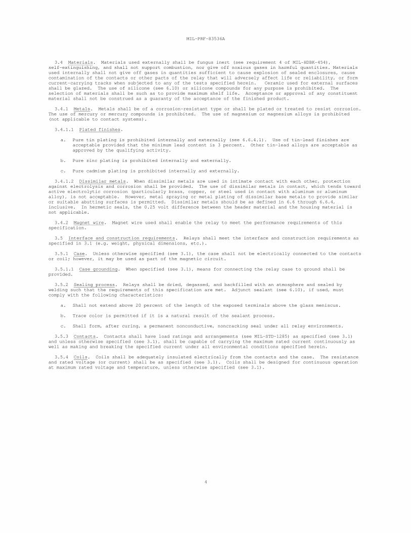
3.5.4.2 Coil terminal identification. Terminals identification shall be marked as specified and inaccordance with MIL-STD-1285. When specified, a bead of contrasting color shall be used to designate the X1(positive, if applicable) terminal (see figure 1 and MIL-STD-1285) (see 3.1).
FIGURE 1. Symbols and markings for terminals.
3.5.4.3 Latching relays. Latching relays with two coils shall be so designed thatenergized simultaneously, the contacts shall not achieve a neutral position (both thenormally open contacts are open). The relay shall be screened as specified in 3.12.8
if both coils arenormally closed andand 4.8.7.8. Specified
dropout-and hold values (voltage or current) and release time are not applicable to latching relays. -
3.5.5 Circuit diagram. The circuit diagram as specified shall be a terminal view. Circuit symbols shall bein accordance with ANSI Y32.2. For relays without an orientation tab, the circuit diagram, as specified (see3.1) shall be orientated so that when the relay is held with the circuit diagram right side up as shown, androtated away from the viewer about a horizontal axis through the diagram until the header terminals face theviewer, then each terminal shall be in the location shown in the circuit diagram.
3.5.6 Mounting means (see 3.1).
3.5.6.1 Bracket. Mounting brackets shall be an integral part of the relay, securely attached thereto in amanner to prevent any movement between the relay and the mounting bracket.
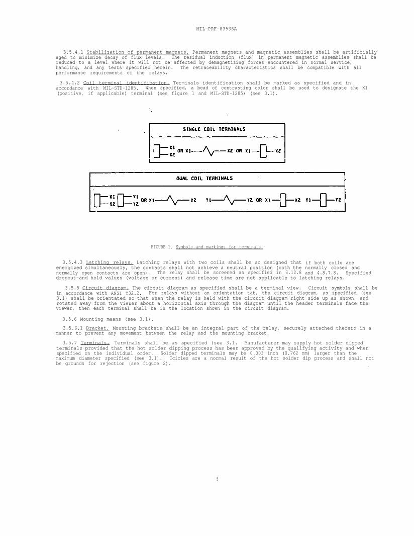
3.5.7 Terminals. Terminals shall be as specified (see 3.1. Manufacturer may supply hot solder dippedterminals provided that the hot solder dipping process has been approved by the qualifying activity and whenspecified on the individual order. Solder dipped terminals may be 0.003 inch (0.762 mm) larger than themaximum diameter specified (see 3.1). Icicles are a normal result of the hot solder dip process and shall notbe grounds for rejection (see figure 2). l
5
MIL-PRF-83536A
NOTES :1. No solder is allowed on the header surface. Components (relay terminals] after solder-dip shall be
capable of meeting method 208 of MIL-STD-202, solderability requirements.2. Solder-coat-thickness shall be 0.0001 inch (.00254 mm) minmum.
. . .
FIGURE 2.Solder-dip acceptability criteria (solder-icicle length limits).
3.5.7.1 Solder-hook terminals. Solder-hook terminals shall be designed to accommodate two conductors, eachrated to carry the maximum rated current of the contact or coil.
3.5.7.2 Wire leads. Wire leads shall be as specified (see 3.1).
3.5.7.2.1 Wire leads,solder pin (SP). Solder pin wire loads shall be as specified (see 3.1).
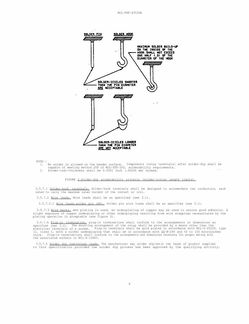
3.5.7.3 Wire marks. men plating is used, an underplating of copper may be used to assure good adhesion. Aslight exposure of copper underplaying or other underplaying resulting from wire wrappings necessitated by theplating operation is acceptable (see figure 3).
3.5.7.4 Plug-in termination. plug-in terminations shall conform to the arrangements or dimensions asspecified (see 3.1). The mounting arrangement of the relay shall be provided by a means other than theelectrical terminals of a socket. Plug-in terminals shall be gold plated in accordance with MIL-G-45204, type11, class I, with a nickel underplaying that shall be in accordance with QQ-N-290 and 50 to 150 microinchesthick. Plug-in terminations shall conform tothe associated sockets in MIL-S-12883.
the arrangements and dimensions necessary for proper mating with
3.5.7.5 Solder dip (retinning) leads. The manufacturer may solder dip/retin the leads of product suppliedto this specification provided the solder dip process has been approved by the qualifying activity.
6
MIL-PRF-83536A
3.5.7.5.1 Qualifying activity approval. Approval of the solder dip process will befollowing options. l Solder dip of gold-plated plug-in leads is not allowed.)criteria shall be in accordance with method 208 of MIL-STD-202:
based on one of theAll visual examination
a. When the original lead finish qualified was hot solder dip lead finish 52 of MIL-STD-1276 (the 200microinch thickness iS not applicable), the manufacturer shall use the same solder dip Process forretinning as is used in the original manufacture of the product.
b. When the lead originally qualified was not hot solder dip lead finish 52 as prescribed above, approvalfor the process to be used for solder dip shall be based on the following test procedure:
(1) six samples for each style and lead finish are subjected to the manufacturer’s solder dip process.Following the solder dip process, the relays shall be subjected to group A2 and group A4inspections.
(2)
(3)
(4)
Three of the six samples are then subjected to the solderability test (see 3.8). NO visualdefects are allowed.
Remaining three samples are subjected to the resistance to soldering heat test (see 3.18).
All six samples shall be subjected to group A2 and group A4 inspection. Minor scratching of theterminals due to insertion into test sockets shall not be cause for rejection.
7
MIL-PRF-83536A
8
3.5.7.5.2 Solder dip/ retinning options. The manufacturer may solder dip/retin as follows:
a. After the 100 percent group A1 screening tests and before the group A3 solderability test.
b. As a corrective action, if the lot fails the group A3 solderability test: Following the solderdip/retinning process of paragraph 4.7.2.2.2.2, as a minimum, insulation resistance (all terminals tocase) shall be tested, and the A4 tests shall be performed, as applicable.
c. For relays that have been subjected to and passed group A inspection: Following the solder dip/retinningprocess, insulation resistance (all terminals to case), seal, and visual/mechanical inspection shall beperformed.
3.5.8 Diodes. Relays supplied with diodes installed internally are not considered electrostatic discharge(ESD) sensitive. However, the diode may be ESD sensitive when not part of the coil circuit or wired internal tothe coil. In such a case, the diode shall be processed in accordance with the requirements specified in paragraph4.2.3. Manufacturers may, at their option, test diodes used internally as specified in method 3015 of MIL-STD-883modified to 16,000 volts to eliminate the need for the ESD protection program described in 4.2.3.
3.6 In-process inspection (see 4.7.1).
3.6.1 Diode in-process screening (see 4.7.1.1). Perform in-process screening as specified. In-processinspection is not required when JAN TX diodes or diodes screened to JAN TX are used. Waiver of in-processscreening requires qualifying activity approval.
3.7 Run-in screening (see 4.8.2). The contact miss detector's monitoring level shall be less than 100 ohms forrelays tested during cycling. Unless otherwise specified (see 3.1), any relay shall have a final insulationresistance measurement of 10,000 megohms or greater.
3.8 Solderability (see 4.8.3). The critical (examination) area of solid wire lead and pin terminals shall beat least 95 percent covered with a continuous new solder coating in accordance with method 208 of MIL-STD-202. For solder-hook terminals greater than .045 inch (1.1430 mm) in diameter, 95 percent of the total length offillet, which is between the standard wrap wire and the terminal, shall be tangent to the surface of the terminalbeing tested, and shall be free of pinholes, voids, etc. A ragged or interrupted line at the point of tangencybetween the fillet and the terminal under test shall be considered a failure.
3.9 Seal (see 4.8.4). There shall be no leakage in excess of 1 x 10 atmospheric cubic centimeters per second-8
of air (atm cm /s).3
3.10 Dielectric withstanding voltage (see 4.8.5). There shall be no leakage current in excess of 1milliampere (mA). After high level life tests, the dielectric withstanding voltage measured at atmospheric orreduced barometric pressure shall be at least 75 percent of the initial value (see 3.1).
3.11 Insulation resistance (see 4.8.6). The insulation resistance shall be 10,000 megohms or more, unlessotherwise specified (see 3.1). After the high level life tests, the insulation resistance shall be 1,000 megohmsor more unless otherwise specified (see 3.1).
MIL-PRF-83536A
9
3.12 Electrical characteristics (see 4.8.7). The following tests as specified in 3.12.1 through 3.12.8inclusive, shall comprise the electrical characteristics tests. Unless otherwise specified, electricalcharacteristics shall be 100 percent inspected and performed in the order as shown below. For the purposes ofthis specification, dropout value (voltage or current), hold value (voltage or current), and release time are notapplicable to latching relays. For latching relays pickup value (voltage or current) is equivalent to latch/resetvoltage, and operate time is equivalent to latch/reset time and shall apply to each coil.
3.12.1 Coil resistance (see 4.8.7.1). The coil resistance shall be as specified (see 3.1).
3.12.2 Maximum coil current (applicable to dc coils when specified and all ac coils) (see 4.8.7.2). Themaximum coil current shall be as specified (see 3.1).
3.12.3 Static contact resistance and contact voltage drop (see 4.8.7.3). Unless otherwise specified (see 3.1),the static contact resistance shall not exceed 0.05 ohm and the contact voltage drop shall not exceed 0.100 voltmaximum. In performing the contact voltage drop tests on plug-in relays, and in the event of a reading thatexceeds the maximum allowable contact voltage drop when measured external to the connector, a measurement may bemade directly at the pins of the relay. If the readings are then within the allowable limits, the relay will beconsidered to have passed.
3.12.4 Specified pickup or latch/reset, hold, and dropout values (voltages) (see 4.8.7.4). The specifiedpickup or latch/reset, hold, and dropout values (voltages) shall be as specified (see 3.1). Specified hold ordropout value (voltage or current) is not applicable to latching relays (see 6.1).
3.12.5 Operate and release time (see 4.8.7.5). The operate and release time shall be as specified (see 3.1). In multipole relays, during each of the operate and the release time measurements, the difference between thefirst moving contact to make and the last moving contact to make shall not exceed 1 ms. This shall be exclusiveof contact bounce. Release time is not applicable to latching relays.
3.12.5.1 Break before make (see 4.8.7.5.1). Moving contacts within a multipole relay shall show no evidence ofany open contact closing before all closed contacts have opened (see 3.1). This applies to either state of therelay.
3.12.6 Contact dynamic characteristics (see 4.8.7.6).
3.12.6.1 Contact bounce (see 4.8.7.6.1). The duration of the contact bounce shall not exceed 1.0 ms unlessotherwise specified (see 3.1).
3.12.6.1.1 Contact break bounce. Contact break bounce (when specified, see 3.1) shall be checked on release ofnormally open contacts and shall not exceed the specified value. Contact break bounce occurs when a closedcontact initially opens, then recloses one or more times before fully opening.
3.12.6.2 Contact stabilization time (see 4.8.7.6.2). The time to reach and maintain a static contactresistance state shall not exceed the value specified (see 3.1).
3.12.7 Coil transient suppression (applicable to dc operated relays with internal coil suppression) (see4.8.7.7). Coils of dc operated relays shall not generate a back electromotive force (EMF) greater than thatspecified (see 3.1).
3.12.8 Neutral screen (applicable to two coil latching relays only) (see 4.8.7.8). Latching relays shalleither not assume a neutral position or shall not fail to latch or reset after assuming a neutral position.
3.13 Thermal shock (see 4.8.8). Insulation resistance, specified pickup or latch/reset, hold, and dropoutvalues (voltages), and operate and release or latch/reset times shall meet the requirements of 3.11, 3.12.4, and3.12.5, respectively, at each temperature extreme. Following the temperature excursions, there shall be nocracking, peeling, or flaking of the finish; dielectric withstanding voltage at sea level atmospheric pressureshall meet the requirements of 3.10.
3.14 Shock (specified pulse) (see 4.8.9). Unless otherwise specified (see 3.1), there shall be no opening ofclosed contacts in excess of 10 microseconds (µs) and there shall be no closure or bridging of open contacts inexcess of 1 µs and no evidence of mechanical or electrical damage.
MIL-PRF-83536A
10
3.15 Vibration (see 4.8.10). Unless otherwise specified (see 3.1), there shall be no opening of closedcontacts in excess of 10 µs and there shall be no closure or bridging of open contacts in excess of 1 µs and noevidence of mechanical or electrical damage.
3.16 Acceleration (unless otherwise specified, see 3.1) (see 4.8.11). The contacts of the relay shall remainin the de-energized position with no voltage applied to the coil and in the energized position when rated coilvoltage is applied to the coil. Latching type relays shall remain in each latched position with no voltage on thecoil. Unless otherwise specified (see 3.1), there shall be no opening of closed contacts in excess of 10 µs andthere shall be no closure or bridging of open contacts in excess of 1 µs and no evidence of mechanical orelectrical damage.
3.17 Terminal strength (see 4.8.12). There shall be no evidence of loosening or breaking of the terminals, norshall there be any other damage which would adversely affect the normal operation of the relay. Bending ofterminals shall not be construed as damage.
3.18 Resistance to soldering heat (see 4.8.13). There shall be no damage which would adversely affect normaloperation of the relay.
3.19 Salt spray (see 4.8.14). There shall be no evidence of breaking, cracking, chipping, or flaking of thefinish, nor exposure of the base metal, due to corrosion, which would adversely affect the application orperformance characteristics of the relay.
3.20 Overload (applicable to high level load ratings only) (see 4.8.15). The voltage drop across closedcontacts shall be less than or equal to 10 percent of the applied load voltage and the voltage across opencontacts shall be 90 percent or more of the applied load voltage. The case-to-ground fuse shall remainelectrically continuous. Relays indicating failure, but not verified as failures per a failure verificationprocedure approved by the qualifying activity, may be returned to test. For failure criteria, see 3.23.
3.21 Rupture (applicable to high level load ratings only) (see 4.8.16). There shall be no electrical failure,such as contact welding or failure to make or break the specified rupture current. The fuse connected betweencase and load system ground or neutral shall remain electrically continuous. Relays indicating failure, but notverified as failures per a failure verification procedure approved by the qualifying activity, may be returned totest. For failure criteria, see 3.23.
3.22 Time current relay characteristics (see 4.8.17). There shall be no evidence of contact welding orsticking and the contact voltage drop shall meet the requirements of 3.12.3 after the test. The fuse connectedbetween case and load system ground or neutral shall remain electrically continuous. Relays indicating failure,but not verified as failures per a failure verification procedure approved by the qualifying activity, may bereturned to test.
3.23 Life (see 4.8.18). For low level testing, the contact miss detector's monitoring level shall be less thanor equal to 100 ohms (unless otherwise specified, see 3.1). For high level testing, the contact miss detector'smonitoring level shall be less than or equal to 10 percent of the applied load voltage and the voltage across opencontacts shall be 90 percent or more of the applied load voltage. Unless otherwise specified, the static contactresistance following cycling shall be no greater than twice the initial specified contact resistance requirement. The case to ground fuse shall remain electrically continuous. Relays having two or more sets of contacts andrated for multiphase (115/200 V ac, three-phase) shall be capable of switching multiphase on adjacent contacts. Phase to phase arcing shall constitute a failure. There shall be no mechanical or electrical failure. Welding ofcontacts, failure to make, carry, or break any rated load shall constitute a failure. The terminal temperaturerise shall not exceed +75 C. (Monitoring of terminal temperature rise applicable to qualification and group Ctesting only). If the lamp load is equal to or less than 0.5 times the motor load rating, the lamp load test neednot be run. Relays indicating failure, but not verified as failures per a failure verification procedure approvedby the qualifying activity, may be returned to test.
MIL-PRF-83536A
11
3.24 Intermediate current (see 4.8.19). During cycling, unless otherwise specified (see 3.1), the resistanceof a closed contact shall be less than or equal to 3 ohms and the voltage across an open contact shall be 90percent or more of applied load voltage. After cycling, the static contact resistance shall be measured at roomambient (25 C) and shall not exceed the limits as specified (see 3.1). Intermediate current shall not beconsidered a low level or high level contact load rating (see 6.1.1). There shall be no mechanical or electricalfailure. Welding of contacts, failure to make, carry or break the load, or failure of the fuse connected betweencase and load system ground or neutral shall constitute a failure. Relays indicating failure, but not verified asfailures per a failure verification procedure approved by the qualifying activity, may be returned to test. During post life tests, failure of a diode shall constitute a failure.
3.25 Mechanical life (see 4.8.20). After cycling, the insulation resistance and dielectric withstandingvoltage shall not exceed the limits as specified (see 3.1) and the operate and release times shall not exceed 120percent of the limits specified (see 3.1). There shall be no mechanical or electrical failure. Failure of thefuse connected between case and load system ground or neutral shall constitute a failure. For relays with diodes,failure of a diode shall constitute a failure. The manufacturer's test system shall have the means to ensure thatthe required number of test cycles have been performed.
3.26 Resistance to solvents (see 4.8.21). The marking shall remain legible.
3.27 Continuous current (see 4.8.22). There shall be no damage such as loosening of terminals, or anydeterioration of performance beyond the limits specified (see 3.1). The terminal temperature rise shall notexceed +75 C.
3.28 Internal moisture (see 4.8.23). The contact load shall be 10 mA to 50 mA at 10 mV dc to 50 mV dc. Whenmeasured within 5 seconds of contact closure, the contact resistance shall not exceed 100 milliohms.
3.29 Marking.
3.29.1 "JAN" brand. The United States Government has adopted, and is exercising legitimate control over thecertification marks "JAN" and "J", respectively, to indicate that items so marked or identified are manufacturedto, and meet all the requirements of specifications. Accordingly, items acquired to, and meeting all of thecriteria specified herein and in applicable specifications shall bear the certification mark "JAN" except thatitems too small to bear the certification mark "JAN" shall bear the letter "J". The "JAN" or "J" shall be placedon the first line above or below the "M" of the PIN or the "J" with the date code (example J8830). Itemsfurnished under contracts or orders which either permit or require deviation from the conditions or requirementsspecified herein or in applicable specifications shall not bear "JAN" or "J". In the event an item fails to meetthe requirements of this specification and the applicable specification sheets or associated specifications, themanufacturer shall remove completely the PIN and the "JAN" or the "J" from the sample tested and also from allitems represented by the sample. The "JAN" or "J" certification mark shall not be used on products acquired tocontractor drawings or specifications. The United States Government has obtained Certificate of RegistrationNumber 504,860 for the certification mark "JAN" and Registration Number 1,586,261 for the certification mark "J".
3.29.2 Identification marking (full). Relays shall be marked in accordance with method I of MIL-STD-1285 andshall include the following information:
a. PIN (see 1.2 and 3.1). The "JAN" or "J" shall not be marked in front of the PIN.
b. "JAN" or "J" brand. The "JAN or "J" shall appear directly above or below the "M" of the PIN.
c. Date code (at the option of the relay manufacturer the "J" with the date code may be used instead of3.29.2b). The date code shall provide traceability (see 4.2.1.1).
d. Source code.
e. Lot symbol (optional).
f. Rated coil voltage (or current) (see 3.1) and when applicable, operating frequency.
g. Coil resistance.
MIL-PRF-83536A
12
h. Contact rating (the highest dc resistive load rating shall be marked) (see 3.1).
i. Circuit diagram (see 3.5.5).
j. Terminal marking (when applicable, see 3.1 and 3.5.4.2).
3.29.3 FR level substitution. With procuring activity approval, relays qualified to lower (better) FR, may besubstituted for higher FR parts. For example, a relay qualified to FR level "P" (0.1 percent/10,000 cycles) maybe substituted for a FR "M" (1.0 percent/10,000 cycles) relay. Relays shall not be remarked unless specified inthe contract or order.
3.29.4 Interchangeability. All parts having the same PIN shall be directly and completely interchangeable witheach other with respect to installation and performance to the extent specified in the specification sheet (see3.1).
3.30 Header glass. Header glass may have small irregularities, such as bubbles, chips, and cracks. Microscopic examination with up to 10 power magnification shall be used. The acceptability of these defects willbe based on figure 4, and the following:
a. Broken or open blisters having sharp edges are not acceptable.
b. Blisters whose diameters exceed one-third the radial distance between terminal and the correspondingheader metal (for a cluster of blisters the combined diameters shall apply) are not acceptable.
c. Foreign material in or on the surface of the glass is not acceptable.
d. Dark spots (pigment concentrations) whose diameters exceed one-third the radial distance between terminaland the corresponding header metal are not acceptable.
e. Circumferential cracks which extend more than 90 percent are not acceptable (see figure 4).
f. Radial cracks whose lengths exceed one-third the distance between the terminal and corresponding headermetal are not acceptable (see figure 4).
g. Tangential cracks which are not confined to a single zone are not acceptable (see figure 4).
h. Surface chips whose lengths or widths exceed one-third the distance between the terminal andcorresponding header metal are not acceptable (see figure 4).
i. Chipped meniscuses are acceptable to the extent that they do not extend below the surface of the glass,and to the extent of 3.30h.
j. Meniscuses which extend up the terminal greater than 0.020 inch (0.51 mm) or one-third the terminaldiameter, whichever is greater, are not acceptable.
k. Peripheral cracks at the boundary of the glass and surrounding header metal are not acceptable.
l. Any terminals which appear to be separated from the glass are not acceptable.
In case of dispute, all relays shall meet the applicable insulation resistance, dielectric withstanding voltage,and seal requirements, regardless of the acceptability of the header glass.
3.31 Workmanship. The relays shall be fabricated in such a manner as to be uniform in quality, and shall befree from cracked or displaced parts, sharp edges, burrs, and other defects that will affect life, serviceability,and appearance.
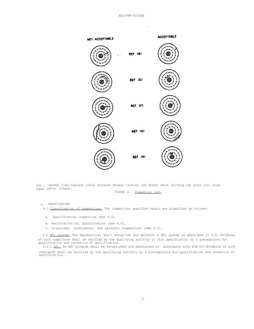
OTE :equal
4.
MIL-PRF-83536A
Dashed lines-indicate radial distance between terminal and header metal dividing the glass into threeparts (zones).
FIGURE 4. Inspection aid.
VERIFICATION
4.1 Classification of inspections. The inspections specified herein are classified as follows:
a. Qualification inspection (see 4.4).
b. Verification of. qualification (see 4.5).
c. In-process, conformance, and periodic inspections (see 4.7).
4.2 OPL system. The manufacturer shall establish and maintain a QPL system as described in 3.3. Evidence
of such compliance shall be verified by the qualifying activity of this specification as a prerequisite forqualification and retention of qualification.
4.2.1 SPC. An SPC program shall be established and maintained in accordance with EIA-557.Evidence of such
comliance shall be verified by the qualifying activity as a prerequisite for qualification and retention of qualification.
13
MIL-PRF-83536A
14
4.2.2 Traceability requirements. The manufacturer shall have a procedure whereby the lot date codes areassigned that incorporates traceability. The following list is the minimum required raw material/component partsand subassemblies for which traceability shall be applicable:
a. Header-contact subassembly with the lot number.
(1) Stationary and moving contact blade assembly (a contact may consist of a contact button and/orcontact blade) (when applicable).
(2) Header with glass to metal sealed leads in place with the lot number.
(3) Return spring(s).
(4) Diodes (when applicable) with the lot number.
(5) Magnets (when applicable).
b. Motor subassembly with the lot number.
(1) Moving contact blade assembly (a contact may consist of a contact button and/or contact blade) (whenapplicable).
(2) Wound coils with the lot number.
(3) Armature assembly.
(4) Diodes (when applicable) with the lot number.
(5) Magnets (when applicable).
(6) Return spring(s) (when applicable).
4.2.3 ESD protection program. This requirement is applicable to all manufacturers who handle ESD componentparts and/or materials in the relay manufacturing and/or testing process. The manufacturer shall establish andmaintain an ESD control program. Evidence of such compliance shall be verified by the qualifying activity of thisspecification as a prerequisite for qualification and continued qualification. As a minimum, this system mustaddress the identification of ESD sub-components and end items, facilities, training, design protection, handlingprocedures, marking, cleaning, preservation, packaging, and quality assurance. A model ESD control program isavailable from the qualifying activity and may be used as a guideline document. Further guidance for ESD controlis available from the EOS/ESD Association and the EIA.
4.3 Inspection conditions. Unless otherwise specified herein, the test conditions specified in the "GENERALREQUIREMENTS" section of MIL-STD-202 shall be considered for referee purposed only. All inspections may beperformed at ambient environmental conditions consistent with industry practice.
4.3.1 Power supply. Unless otherwise specified herein, the power supply shall have no more than 10 percentregulation at 110 percent of the specified test load current. A dc power supply shall have no more than 5 percentripple voltage. An ac power supply shall be within 1 percent of the specified frequency and shall be sinusoidalwith a form factor between 0.95 and 1.25.
4.3.2 Grounding. Unless otherwise specified (see 3.1), the negative side of the dc power supply shall begrounded. One side of single phase ac power supply shall be grounded.
4.3.3 Load conditions during tests. The coil(s) of the relay under test shall have one side connected to thecoil power supply ground. All tests during which the contacts are loaded and being cycled, except dielectricwithstanding voltage, shall be conducted with the case of the relay connected to the power supply ground orneutral through a normal blow fuse rated at 5 percent of the contact load maximum, but not less than 0.100 ampere.For relays with nongrounded case ratings, tests for isolated-case ratings may be made with the case electricallyisolated from the power supply ground.
MIL-PRF-83536A
15
4.3.4 Testing devices. Devices used in the testing of relays shall not load the contacts above 10 mA resistiveat 6 V dc or peak ac maximum open circuit unless otherwise specified herein.
4.3.5 Mounting relays for ambient temperature tests. When the relays are subjected to the testing specified in4.8.19 (intermediate current), they may be mounted on a heat sink in accordance with the following:
a. Each relay may be attached by its normal mounting means to a 0.063 inch (1.59 mm) thick minimum, flataluminum plate heat sink. The heat sink shall be designed to place every relay in the center of its ownsquare space whose total surface area (both sides) is eight times the outside surface area of the relay,excluding mounting. Relays without mounts shall be held to the heat sink with a metal strap 0.250 inch(6.35 mm) wide by 0.015 inch (0.38 mm) maximum thickness. The heat sink assembly shall be suspended bytwine or other nonheat conducting material. The leads shall not constitute a heat sink.
b. Chamber temperature shall be controlled to maintain the temperature at the specified ambient extremes(see 3.1).
4.3.6 Methods of examination and test. Application of coil power to relays under test shall be such that pluspolarity is applied to the color coded terminal when applicable; or to the lower numbered terminal when colorcoding is not used. Testing of latching relays shall be repeated with the relay in each operated position.
4.3.7 Tolerances. Unless otherwise specified (see 3.1), all electrical, environmental, and mechanicalparameters shall have a tolerance of ±10 percent.
4.3.8 Alternate test equipment. Test circuits and test equipment herein are intended to provide guidance tothe relay manufacturer. Use of any alternate test circuits and/or test equipment shall be approved by thequalifying activity prior to use.
4.3.9 Test equipment and inspection facilities. The manufacturer shall establish and maintain a calibrationsystem in accordance with ANSI/NCSL Z540-1, ISO-10012-1, or equivalent system as approved by the qualifyingactivity.
4.4 Qualification inspection. Qualification inspection shall be performed at a laboratory acceptable to theGovernment (see 6.3) on sample units produced with equipment and procedures normally used in production. Variables measurements are acceptable.
4.4.1 Qualification. Qualification shall be granted at the "L" or "M" FR initially and shall be based onresults of the qualification inspection specified in table II. A certification of construction to the materialsrequirements of 3.4, and the interface and construction requirements of 3.5 shall accompany the submission ofqualification inspection results to the qualifying activity.
4.4.1.1 Sample size. The number of relays to be subjected to qualification inspection shall be as specified intable II. The sample shall be selected from a production run and shall be produced with equipment or proceduresnormally used in production. The qualification sample shall be as defined in table II.
4.4.2 Inspection routine. Sample units shall be subjected to qualification inspection outlined in table II, inthe order shown, except that group Q2 through group Q10 inclusive, may be conducted concurrently. All sampleunits shall be subjected to the inspections of Q1. These sample units shall then be divided into nine groups asspecified in table II and subjected to the inspection specified for their particular group.
4.4.3 Failures. Failures in excess of those allowed in table II shall be cause for refusal to grantqualification approval.
MIL-PRF-83536A
16
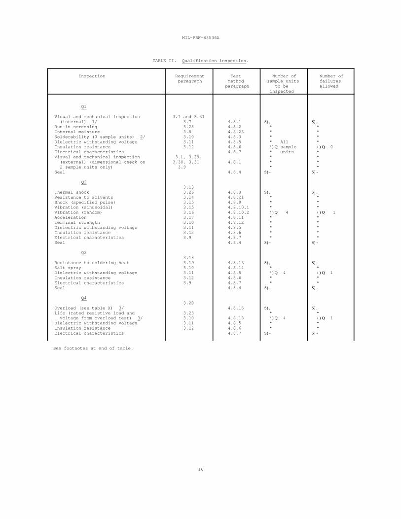
TABLE II. Qualification inspection.
Inspection Requirement Test Number of Number of paragraph method sample units failures
paragraph to be allowed inspected
Q1
Visual and mechanical inspection 3.1 and 3.31 (internal) 1/ 3.7 4.8.1 S), S), Run-in screening 3.28 4.8.2 * * Internal moisture 3.8 4.8.23 * * Solderability (3 sample units) 2/ 3.10 4.8.3 * * Dielectric withstanding voltage 3.11 4.8.5 * All * Insulation resistance 3.12 4.8.6 /)Q sample /)Q 0 Electrical characteristics 4.8.7 * units * Visual and mechanical inspection 3.1, 3.29, * * (external) (dimensional check on 3.30, 3.31 4.8.1 * * 2 sample units only) 3.9 * * Seal 4.8.4 S)- S)-
Q2
Thermal shock 3.26 4.8.8 S), S), Resistance to solvents 3.14 4.8.21 * * Shock (specified pulse) 3.15 4.8.9 * * Vibration (sinusoidal) 3.15 4.8.10.1 * * Vibration (random) 3.16 4.8.10.2 /)Q 4 /)Q 1 Acceleration 3.17 4.8.11 * * Terminal strength 3.10 4.8.12 * * Dielectric withstanding voltage 3.11 4.8.5 * * Insulation resistance 3.12 4.8.6 * * Electrical characteristics 3.9 4.8.7 * * Seal 4.8.4 S)- S)-
Q3
Resistance to soldering heat 3.19 4.8.13 S), S), Salt spray 3.10 4.8.14 * * Dielectric withstanding voltage 3.11 4.8.5 /)Q 4 /)Q 1 Insulation resistance 3.12 4.8.6 * * Electrical characteristics 3.9 4.8.7 * * Seal 4.8.4 S)- S)-
Q4
Overload (see table X) 3/ 4.8.15 S), S), Life (rated resistive load and 3.23 * * voltage from overload test) 3/ 3.10 4.8.18 /)Q 4 /)Q 1 Dielectric withstanding voltage 3.11 4.8.5 * * Insulation resistance 3.12 4.8.6 * * Electrical characteristics 4.8.7 S)- S)-
3.13
3.18
3.20
See footnotes at end of table.
MIL-PRF-83536A
17
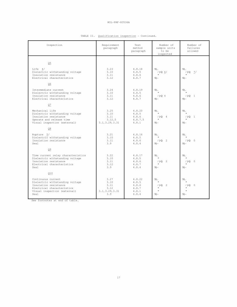
TABLE II. Qualification inspection - Continued.
Inspection Requirement Test Number of Number of paragraph method sample units failures
paragraph to be allowed inspected
Q5
Life 4/ 3.23 4.8.18 S), S), Dielectric withstanding voltage 3.10 4.8.5 /)Q 6/ /)Q 7/ Insulation resistance 3.11 4.8.6 * * Electrical characteristics 3.12 4.8.7 S)- S)-
Q6
Intermediate current 3.24 4.8.19 S), S), Dielectric withstanding voltage 3.10 4.8.5 * * Insulation resistance 3.11 4.8.6 /)Q 4 /)Q 1 Electrical characteristics 3.12 4.8.7 S)- S)-
Q7
Mechanical life 3.25 4.8.20 S), S), Dielectric withstanding voltage 3.10 4.8.5 * * Insulation resistance 3.11 4.8.6 /)Q 4 /)Q 1 Operate and release time 3.12.5 4.8.7.5 * * Visual inspection (external) 3.1,3.29,3.31 4.8.1 S)- S)-
Q8
Rupture 5/ 3.21 4.8.16 S), S), Dielectric withstanding voltage 3.10 4.8.5 * * Insulation resistance 3.11 4.8.6 /)Q 2 /)Q 0 Seal 3.9 4.8.4 S)- S)-
Q9
Time current relay characteristics 3.22 4.8.17 S), S), Dielectric withstanding voltage 3.10 4.8.5 * * Insulation resistance 3.11 4.8.6 /)Q 2 /)Q 0 Electrical characteristics 3.12 4.8.7 * * Seal 3.9 4.8.4 S)- S)-
Q10
Continuous current 3.27 4.8.22 S), S), Dielectric withstanding voltage 3.10 4.8.5 * * Insulation resistance 3.11 4.8.6 /)Q 2 /)Q 0 Electrical characteristics 3.12 4.8.7 * * Visual inspection (external) 3.1,3.29,3.31 4.8.1 * * Seal 3.9 4.8.4 S)- S)-
See footnotes at end of table.
MIL-PRF-83536A
18
TABLE II. Qualification inspection - Continued.
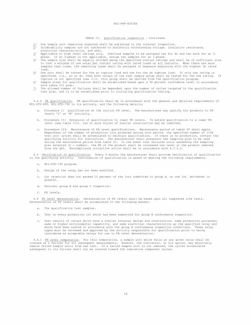
1/ One sample unit remaining unsealed shall be subjected to the internal inspection. 2/ Solderability samples are not subjected to dielectric withstanding voltage, insulation resistance,
electrical characteristics, and seal.3/ Applicable to high level ratings only. Overload samples to be assigned two for dc and two each for ac 3-
phase. If ac 3-phase is not applicable, assign two samples for ac 1-phase.4/ The sample size shall be equally divided among the specified contact ratings and shall be of sufficient size
to test a minimum of one relay per contact rating with rated loads on all contacts. When there are moresamples than loads, the remaining loads shall be assigned in sequence beginning with the highest dc ratedload.
5/ One unit shall be tested for the ac rupture load and one for the dc rupture load. If only one rating isspecified, i.e., ac or dc, then both relays of the test sample group shall be tested for the one rating. Ifrupture is not specified (see 3.1), this group shall be omitted from the qualification program.
6/ Sample sizes for qualification shall be established based upon a 90 percent confidence level in accordancewith table III plan.
7/ The allowed number of failures shall be dependent upon the number of cycles targeted in the qualificationtest plan, and is to be established prior to initiating qualification testing.
4.4.4 FR qualification. FR qualification shall be in accordance with the general and detailed requirements ofMIL-STD-690, MIL-STD-790 in its entirety, and the following details:
a. Procedure I: Qualification at the initial FR level. The manufacturer may qualify his products to FRlevels "L" or "M" initially.
b. Procedure II: Extension of qualification to lower FR levels. To extend qualification to a lower FRlevel (see table III), two or more styles of similar construction may be combined.
c. Procedure III: Maintenance of FR level qualifications. Maintenance period of table IV shall apply. Regardless of the number of production lots produced during this period, the specified number of lifetest unit cycles shall be accumulated to maintain qualification. If there is no production, contact thequalifying activity for instruction. The manufacturer shall preselect the sampling plan to be usedduring the maintenance period from table IV. In the event that failures occur exceeding the samplingplan selected (C = number), the FR of the product shall be increased one level or the product removedfrom the QPL. Noncompliance corrective action shall be in accordance with 4.7.3.3.
4.5 Verification of qualification. Every 6 months the manufacturer shall provide verification of qualificationto the qualifying activity. Continuation of qualification is based on meeting the following requirements.
a. MIL-STD-790 program.
b. Design of the relay has not been modified.
c. Lot rejection does not exceed 10 percent of the lots submitted to group A, or one lot, whichever isgreater.
d. Periodic group B and group C inspection.
f. FR levels.
4.6 FR level determination. Determination of FR levels shall be based upon all completed life tests. Determination of FR levels shall be accumulated in the following manner:
a. The qualification test samples.
b. Test on every production lot which has been submitted for group B conformance inspection.
c. Test results of relays which have a similar internal design and construction, same production processes,same or higher environmental capability, and same electrical characteristics as the qualified relay andwhich have been tested in accordance with the group B conformance inspection conditions. These relaytypes must be reviewed and approved by the activity responsible for qualification prior to beingconsidered as acceptable relays for use in FR level determination.
4.6.1 FR level computation. For this computation, a sample unit which fails at any given cycle shall beclassed as a failure for all subsequent measurements. However, the contractor, at his option, may physicallyremove failed sample units from the test. If a failed sample unit is not removed, the cycles accumulatedsubsequent to its failure shall not be counted toward the cumulative component cycles.
MIL-PRF-83536A
19
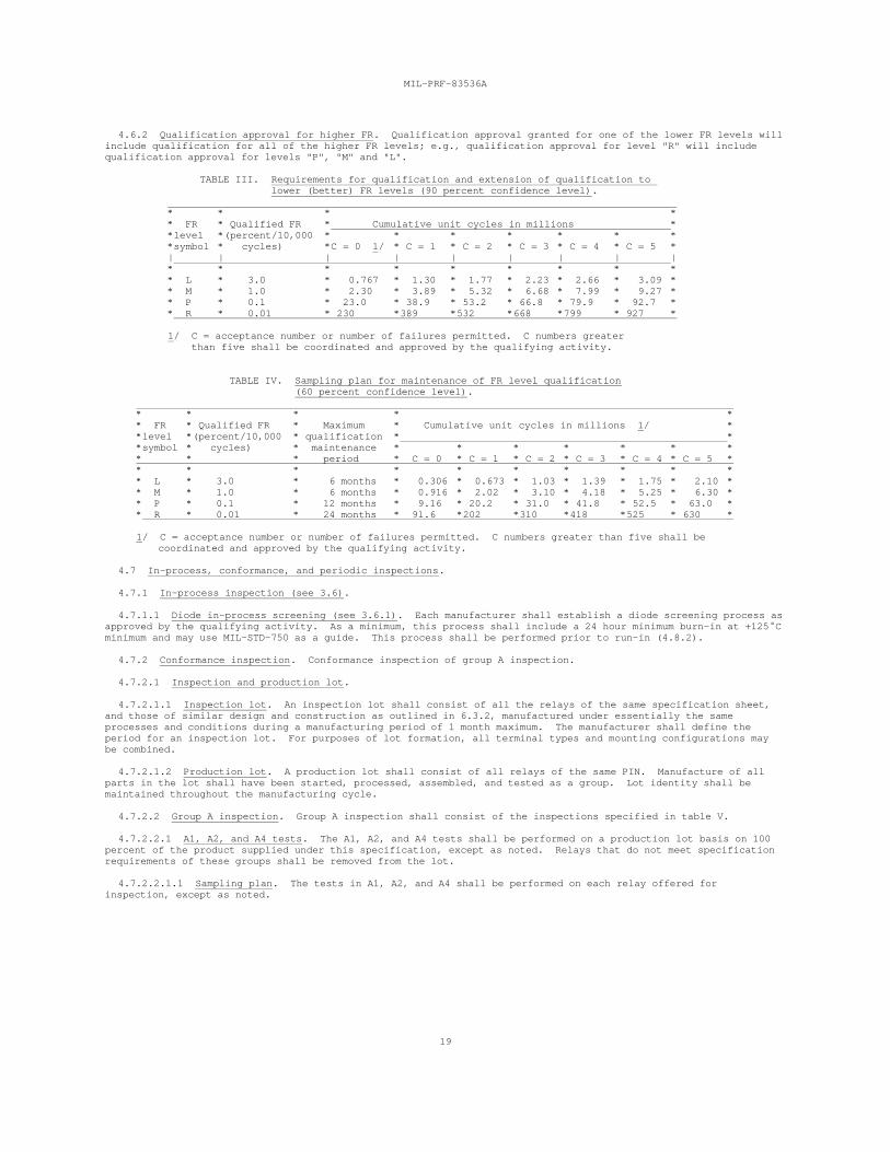
4.6.2 Qualification approval for higher FR. Qualification approval granted for one of the lower FR levels willinclude qualification for all of the higher FR levels; e.g., qualification approval for level "R" will includequalification approval for levels "P", "M" and "L".
TABLE III. Requirements for qualification and extension of qualification to lower (better) FR levels (90 percent confidence level).
* * * ** FR * Qualified FR * Cumulative unit cycles in millions **level *(percent/10,000 * * * * * * **symbol * cycles) *C = 0 1/ * C = 1 * C = 2 * C = 3 * C = 4 * C = 5 *| | | | | | | | |* * * * * * * * ** L * 3.0 * 0.767 * 1.30 * 1.77 * 2.23 * 2.66 * 3.09 ** M * 1.0 * 2.30 * 3.89 * 5.32 * 6.68 * 7.99 * 9.27 ** P * 0.1 * 23.0 * 38.9 * 53.2 * 66.8 * 79.9 * 92.7 ** R * 0.01 * 230 *389 *532 *668 *799 * 927 *
1/ C = acceptance number or number of failures permitted. C numbers greater than five shall be coordinated and approved by the qualifying activity.
TABLE IV. Sampling plan for maintenance of FR level qualification (60 percent confidence level).
* * * * ** FR * Qualified FR * Maximum * Cumulative unit cycles in millions 1/ **level *(percent/10,000 * qualification * **symbol * cycles) * maintenance * * * * * * ** * * period * C = 0 * C = 1 * C = 2 * C = 3 * C = 4 * C = 5 ** * * * * * * * * ** L * 3.0 * 6 months * 0.306 * 0.673 * 1.03 * 1.39 * 1.75 * 2.10 ** M * 1.0 * 6 months * 0.916 * 2.02 * 3.10 * 4.18 * 5.25 * 6.30 ** P * 0.1 * 12 months * 9.16 * 20.2 * 31.0 * 41.8 * 52.5 * 63.0 ** R * 0.01 * 24 months * 9l.6 *202 *310 *418 *525 * 630 *
1/ C = acceptance number or number of failures permitted. C numbers greater than five shall be coordinated and approved by the qualifying activity.
4.7 In-process, conformance, and periodic inspections.
4.7.1 In-process inspection (see 3.6).
4.7.1.1 Diode in-process screening (see 3.6.1). Each manufacturer shall establish a diode screening process asapproved by the qualifying activity. As a minimum, this process shall include a 24 hour minimum burn-in at +125 Cminimum and may use MIL-STD-750 as a guide. This process shall be performed prior to run-in (4.8.2).
4.7.2 Conformance inspection. Conformance inspection of group A inspection.
4.7.2.1 Inspection and production lot.
4.7.2.1.1 Inspection lot. An inspection lot shall consist of all the relays of the same specification sheet,and those of similar design and construction as outlined in 6.3.2, manufactured under essentially the sameprocesses and conditions during a manufacturing period of 1 month maximum. The manufacturer shall define theperiod for an inspection lot. For purposes of lot formation, all terminal types and mounting configurations maybe combined.
4.7.2.1.2 Production lot. A production lot shall consist of all relays of the same PIN. Manufacture of allparts in the lot shall have been started, processed, assembled, and tested as a group. Lot identity shall bemaintained throughout the manufacturing cycle.
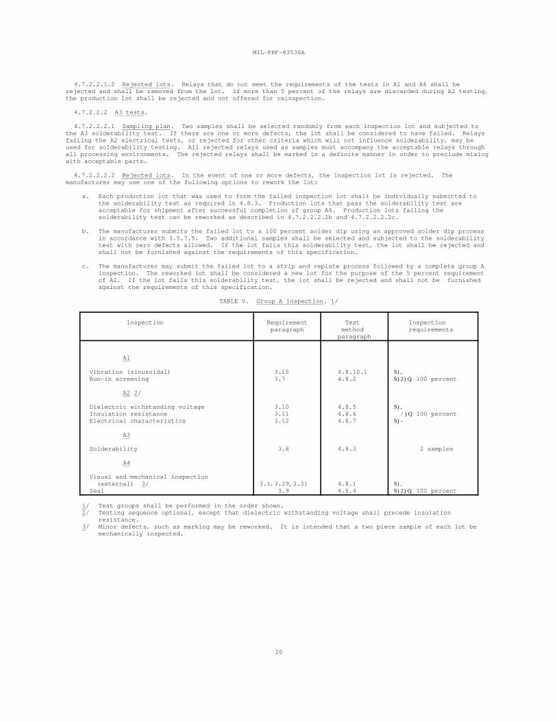
4.7.2.2 Group A inspection. Group A inspection shall consist of the inspections specified in table V.
4.7.2.2.1 A1, A2, and A4 tests. The A1, A2, and A4 tests shall be performed on a production lot basis on 100percent of the product supplied under this specification, except as noted. Relays that do not meet specificationrequirements of these groups shall be removed from the lot.
4.7.2.2.1.1 Sampling plan. The tests in A1, A2, and A4 shall be performed on each relay offered forinspection, except as noted.
MIL-PRF-83536A
20
4.7.2.2.1.2 Rejected lots. Relays that do not meet the requirements of the tests in A1 and A4 shall berejected and shall be removed from the lot. If more than 5 percent of the relays are discarded during A2 testing,the production lot shall be rejected and not offered for reinspection.
4.7.2.2.2 A3 tests.
4.7.2.2.2.1 Sampling plan. Two samples shall be selected randomly from each inspection lot and subjected tothe A3 solderability test. If there are one or more defects, the lot shall be considered to have failed. Relaysfailing the A2 electrical tests, or rejected for other criteria which will not influence solderability, may beused for solderability testing. All rejected relays used as samples must accompany the acceptable relays throughall processing environments. The rejected relays shall be marked in a definite manner in order to preclude mixingwith acceptable parts.
4.7.2.2.2.2 Rejected lots. In the event of one or more defects, the inspection lot is rejected. Themanufacturer may use one of the following options to rework the lot:
a. Each production lot that was used to form the failed inspection lot shall be individually submitted tothe solderability test as required in 4.8.3. Production lots that pass the solderability test areacceptable for shipment after successful completion of group A4. Production lots failing thesolderability test can be reworked as described in 4.7.2.2.2.2b and 4.7.2.2.2.2c.
b. The manufacturer submits the failed lot to a 100 percent solder dip using an approved solder dip processin accordance with 3.5.7.5. Two additional samples shall be selected and subjected to the solderabilitytest with zero defects allowed. If the lot fails this solderability test, the lot shall be rejected andshall not be furnished against the requirements of this specification.
c. The manufacturer may submit the failed lot to a strip and replate process followed by a complete group Ainspection. The reworked lot shall be considered a new lot for the purpose of the 5 percent requirementof A2. If the lot fails this solderability test, the lot shall be rejected and shall not be furnishedagainst the requirements of this specification.
TABLE V. Group A inspection. 1/
Inspection Requirement Test Inspection paragraph method requirements
paragraph
A1
Vibration (sinusoidal) 3.15 4.8.10.1 S), Run-in screening 3.7 4.8.2 S)2)Q 100 percent
A2 2/
Dielectric withstanding voltage 3.10 4.8.5 S), Insulation resistance 3.11 4.8.6 /)Q 100 percent Electrical characteristics 3.12 4.8.7 S)-
A3
Solderability 3.8 4.8.3 2 samples
A4
Visual and mechanical inspection (external) 3/ 3.1,3.29,3.31 4.8.1 S), Seal 3.9 4.8.4 S)2)Q 100 percent
1/ Test groups shall be performed in the order shown.2/ Testing sequence optional, except that dielectric withstanding voltage shall precede insulation
resistance.3/ Minor defects, such as marking may be reworked. It is intended that a two piece sample of each lot be
mechanically inspected.
MIL-PRF-83536A
21
4.7.3 Periodic inspections. Periodic inspections shall consist of group B and group C. Except where theresults of these inspections show noncompliance with the applicable requirements, delivery of products which havepassed group A shall not be delayed pending the results of these periodic inspections.
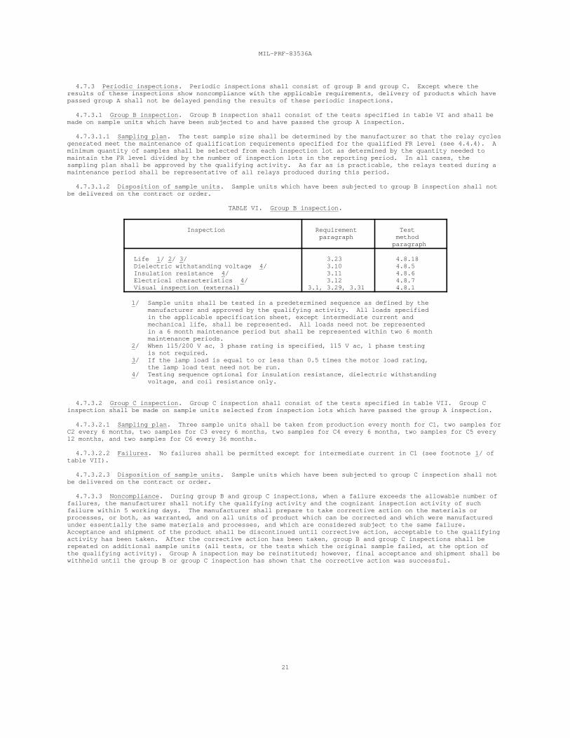
4.7.3.1 Group B inspection. Group B inspection shall consist of the tests specified in table VI and shall bemade on sample units which have been subjected to and have passed the group A inspection.
4.7.3.1.1 Sampling plan. The test sample size shall be determined by the manufacturer so that the relay cyclesgenerated meet the maintenance of qualification requirements specified for the qualified FR level (see 4.4.4). Aminimum quantity of samples shall be selected from each inspection lot as determined by the quantity needed tomaintain the FR level divided by the number of inspection lots in the reporting period. In all cases, thesampling plan shall be approved by the qualifying activity. As far as is practicable, the relays tested during amaintenance period shall be representative of all relays produced during this period.
4.7.3.1.2 Disposition of sample units. Sample units which have been subjected to group B inspection shall notbe delivered on the contract or order.
TABLE VI. Group B inspection.
Inspection Requirement Test paragraph method
paragraph
Life 1/ 2/ 3/ 3.23 4.8.18 Dielectric withstanding voltage 4/ 3.10 4.8.5 Insulation resistance 4/ 3.11 4.8.6 Electrical characteristics 4/ 3.12 4.8.7 Visual inspection (external) 3.1, 3.29, 3.31 4.8.1
1/ Sample units shall be tested in a predetermined sequence as defined by themanufacturer and approved by the qualifying activity. All loads specifiedin the applicable specification sheet, except intermediate current andmechanical life, shall be represented. All loads need not be representedin a 6 month maintenance period but shall be represented within two 6 monthmaintenance periods.
2/ When 115/200 V ac, 3 phase rating is specified, 115 V ac, 1 phase testingis not required.
3/ If the lamp load is equal to or less than 0.5 times the motor load rating,the lamp load test need not be run.
4/ Testing sequence optional for insulation resistance, dielectric withstandingvoltage, and coil resistance only.
4.7.3.2 Group C inspection. Group C inspection shall consist of the tests specified in table VII. Group Cinspection shall be made on sample units selected from inspection lots which have passed the group A inspection.
4.7.3.2.1 Sampling plan. Three sample units shall be taken from production every month for C1, two samples forC2 every 6 months, two samples for C3 every 6 months, two samples for C4 every 6 months, two samples for C5 every12 months, and two samples for C6 every 36 months.
4.7.3.2.2 Failures. No failures shall be permitted except for intermediate current in C1 (see footnote 1/ oftable VII).
4.7.3.2.3 Disposition of sample units. Sample units which have been subjected to group C inspection shall notbe delivered on the contract or order.
4.7.3.3 Noncompliance. During group B and group C inspections, when a failure exceeds the allowable number offailures, the manufacturer shall notify the qualifying activity and the cognizant inspection activity of suchfailure within 5 working days. The manufacturer shall prepare to take corrective action on the materials orprocesses, or both, as warranted, and on all units of product which can be corrected and which were manufacturedunder essentially the same materials and processes, and which are considered subject to the same failure. Acceptance and shipment of the product shall be discontinued until corrective action, acceptable to the qualifyingactivity has been taken. After the corrective action has been taken, group B and group C inspections shall berepeated on additional sample units (all tests, or the tests which the original sample failed, at the option ofthe qualifying activity). Group A inspection may be reinstituted; however, final acceptance and shipment shall bewithheld until the group B or group C inspection has shown that the corrective action was successful.
MIL-PRF-83536A
22
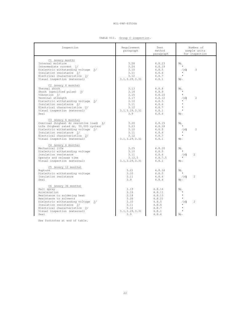
TABLE VII. Group C inspection.
Inspection Requirement Test Number of paragraph method sample units
paragraph for inspection
C1 (every month) Internal moisture 3.28 4.8.23 S), Intermediate current 1/ 3.24 4.8.19 * Dielectric withstanding voltage 2/ 3.10 4.8.5 /)Q 3 Insulation resistance 2/ 3.11 4.8.6 * Electrical characteristics 2/ 3.12 4.8.7 * Visual inspection (external) 3.1,3.29,3.31 4.8.1 S)-
C2 (every 6 months) Thermal shock 3.13 4.8.8 S), Shock (specified pulse) 3/ 3.14 4.8.9 * Vibration 3/ 3.15 4.8.10 * Terminal strength 3.17 4.8.12 /)Q 2 Dielectric withstanding voltage 2/ 3.10 4.8.5 * Insulation resistance 2/ 3.11 4.8.6 * Electrical characteristics 2/ 3.12 4.8.7 * Visual inspection (external) 3.1,3.29,3.31 4.8.1 * Seal 3.9 4.8.4 S)-
C3 (every 6 months) Overload (highest dc resistive load) 4/ 3.20 4.8.15 S), Life (highest rated dc, 50,000 cycles) 3.23 4.8.18 * Dielectric withstanding voltage 2/ 3.10 4.8.5 /)Q 2 Insulation resistance 2/ 3.11 4.8.6 * Electrical characteristics 2/ 3.12 4.8.7 * Visual inspection (external) 3.1,3.29,3.31 4.8.1 S)-
C4 (every 6 months) Mechanical life 3.25 4.8.20 S), Dielectric withstanding voltage 3.10 4.8.5 * Insulation resistance 3.11 4.8.6 /)Q 2 Operate and release time 3.12.5 4.8.7.5 * Visual inspection (external) 3.1,3.29,3.31 4.8.1 S)-
C5 (every 12 months) Rupture 3.21 4.8.16 S), Dielectric withstanding voltage 3.10 4.8.5 * Insulation resistance 3.11 4.8.6 /)Q 2 Seal 3.9 4.8.4 S)-
C6 (every 36 months) Salt spray 3.19 4.8.14 S), Acceleration 3.16 4.8.11 * Resistance to soldering heat 3.18 4.8.13 * Resistance to solvents 3.26 4.8.21 * Dielectric withstanding voltage 2/ 3.10 4.8.5 /)Q 2 Insulation resistance 2/ 3.11 4.8.6 * Electrical characteristics 2/ 3.12 4.8.7 * Visual inspection (external) 3.1,3.29,3.31 4.8.1 * Seal 3.9 4.8.4 S)-
See footnotes at end of table.
MIL-PRF-83536A
23
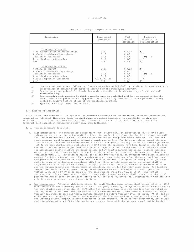
TABLE VII. Group C inspection - Continued.
Inspection Requirement Test Number of paragraph method sample units
paragraph for inspection
C7 (every 36 months) Time current relay characteristics 3.22 4.8.17 S), Dielectric withstanding voltage 3.10 4.8.5 * Insulation resistance 3.11 4.8.6 /)Q 2 Electrical characteristics 3.12 4.8.7 * Seal 3.9 4.8.4 S)-
C8 (every 36 months) Continuous current 3.27 4.8.22 S), Dielectric withstanding voltage 3.10 4.8.5 * Insulation resistance 3.11 4.8.6 /)Q 2 Electrical characteristics 3.12 4.8.7 * Visual inspection (external) 3.1,3.29,3.31 4.8.1 * Seal 3.9 4.8.4 S)-
1/ One intermediate current failure per 6 month retention period shall be permitted in accordance withFR groupings of similar relay types as approved by the qualifying activity.
2/ Testing sequence optional for insulation resistance, dielectric withstanding voltage, and coilresistance only.
3/ Each mounting configuration to which a manufacturer is qualified will be represented during thenormal continuous periodic testing period. It will usually take more than one periodic testingperiod to achieve testing of all of the applicable mountings.
4/ Applicable to high level load ratings.
4.8 Methods of inspection.
4.8.1 Visual and mechanical. Relays shall be examined to verify that the materials, external interface andconstruction, physical dimensions (only required where mechanical inspection is specified), marking, andworkmanship are in accordance with the applicable requirements (see 3.1, 3.4, 3.5, 3.29, 3.30, and 3.31). Paragraph 3.30 inspection requirements apply only when indicated.
4.8.2 Run-in screening (see 3.7).
a. High temperature. For qualification inspection only; relays shall be subjected to +125 C with rated voltage or current on the coil circuit for 1 hour for nonlatching relays; for latching relays, one coilshall be energized for 0.5 hour. At the end of this period, the pickup value (voltage), or latch andreset voltage, shall be measured to determine compliance to 3.1. For latching relays, repeat the testafter the other coil has been energized for 0.5 hour. For group A testing, relays shall be subjected to+125 C; the test chamber shall stabilize at +125 C after the specimens have been inserted into the testchamber. The test shall be performed with rated voltage or current on the coil for 15 minutes minimumfor nonlatching relays weighing one ounce or less and 30 minutes minimum for relays weighing over oneounce. At the end of each period, the specified pickup value (voltage) shall be measured to determinecompliance with 3.1. For latching relays, one of the two coils shall be energized with rated voltage orcurrent for 7.5 minutes minimum. For latching relays, repeat this test after the other coil has beenenergized with rated voltage or current for 7.5 minutes minimum. The specified pickup value (voltage)shall be measured to determine compliance with 3.1. While at this temperature, the relays shall besubjected to a 2,500 cycle run-in test. The cycling rate shall be calculated using the formulas belowand the maximum operate and release times as specified, see 3.1 for the relay under test. For latchingrelays, use the latch/reset times. Relays shall have the contacts loaded as follows: Open circuit loadvoltage 10 mV dc to 50 mV dc or peak ac. The load current shall be 10 µA to 50 µA. The contactresistance or voltage drop, as applicable, of each pair of mated contacts shall be monitored during 40percent minimum of each "on" and each "off" period. The test equipment shall automatically turn off whena failure occurs, or shall record every failure.
b. Low temperature. Following high temperature, for qualification only, relays shall be subjected to -65 Cwith the coil or coils de-energized for 1 hour. For group A testing, relays shall be subjected to -65 C;the test chamber shall stabilize at -65 C after the specimens have been inserted into the test chamber. The test shall be performed with the coil or coils de-energized for fifteen minutes minimum for relaysweighing one ounce or less and thirty minutes minimum for relays weighing over one ounce. At the end ofeither period, the specified dropout value (voltage) shall be measured to determine compliance with 3.1. For latching relays, dropout voltage measurement is not required. While at this temperature, the relaysshall be subjected to a 2,500 cycle run-in test in accordance with the procedure outlined in 4.8.2a.
MIL-PRF-83536A
24
4.8.2.1 Cycling-rate. The cycle rate shall be a maximum of 0.1/(maximum operate time (seconds) plus maximumrelease time (seconds)) cycles per second where the operate and release times are those of the relay under test.
Maximum cycle rate 0.1(cycles per second) =
Maximum operate time + maximum release time (seconds) (seconds)
For latching relays: 0.1Maximum cycle rate =
2X maximum latch/reset time (seconds)
4.8.3 Solderability (see 3.8). Relays shall be tested in accordance with method 208 of MIL-STD-202. Thefollowing details and exceptions shall apply: All terminations of each part shall be tested.
4.8.4 Seal (see 3.9). Relays shall be tested in accordance with 4.8.4.1 or 4.8.4.2, as applicable. In case ofdispute, method 1014 of MIL-STD-883, test condition B shall govern.
4.8.4.1 Relays sealed with a tracer gas. Relays sealed with a tracer gas shall be tested in accordance withmethod 112 of MIL-STD-202, or at the option of the manufacturer, method 1014 of MIL-STD-883. The followingdetails shall apply: Method 112 of MIL-STD-202:
a. Test condition C, procedure IV. Relays shall be back-filled with a helium tracer gas (90 percent dry gasand 10 percent helium). For gross leak, silicone oil shall not be used.
b. Leakage rate sensitivity: 1 X 10 atm cm /s of air.-8 3
c. Measurements after test: Not applicable.
d. Method 1014 of MIL-STD-883, test condition B (gross leak test not required).
4.8.4.2 Relays sealed without a tracer gas. Relays sealed without a tracer gas shall be tested in accordancewith method 1014 of MIL-STD-883. At the option of the manufacturer, 4.8.4.2a or 4.8.4.2b may be used. Thefollowing details shall apply:
a. Method 1014 MIL-STD-883:
(1) Test condition A1 or A2.
(2) Measurements after test: Perform a gross leak test in accordance with method 112 of MIL-STD-202,test condition A, B, or D. Silicone oil shall not be used. At the option of the manufacturer, thegross leak test of method 1014 of MIL-STD-883, test condition C, may be used.
b. Method 1014 of MIL-STD-883, test condition B (gross leak test not required).
4.8.4.3 Radioisotope dry gross leak test (optional). This test shall be used only to test devices thatinternally contain some krypton-85 absorbing medium, such as electrical insulation, organic, or molecular sievematerial. This test shall be permitted only if the following requirements are met:
a. A .005 inch (0.1270 mm) to .010 inch (0.2540 mm) diameter hole shall be made in a representative unit ofthe device to be tested. (This is a one time test that remains in effect until a design change is madein the relay internal construction.)
b. The device shall be subjected to this test condition. If the device exhibits a hard failure, this testcondition may be used for those devices represented by the test unit. If the device does not fail, thistest shall not be used and instead a +125 C fluorocarbon gross leak shall be performed in accordance withmethod 112, MIL-STD-202, test condition D, except the specimen shall be observed from the instant ofimmersion for 1 minute minimum to 3 minutes maximum.
4.8.4.3.1 Apparatus. The following apparatus shall be required for this test:
a. Radioactive tracer gas activation console containing krypton-85/dry nitrogen gas mixture.
b. Counting station with sufficient sensitivity to determine the radiation level of krypton-85 tracer gasinside the device.
c. Tracer gas mixture: Krypton-85/dry nitrogen with a minimum allowable specific activity of 100microcuries per atmosphere cubic centimeter. The specific activity of the krypton-85/dry nitrogenmixture shall be a known value and determined on a once-a-month basis as a minimum.
MIL-PRF-83536A
25
4.8.4.3.2 Procedure. The devices shall be placed in a radioactive tracer gas activation tank and the tankshall be evacuated to a pressure not to exceed 0.5 torr. The devices shall then be subjected to a minimum of 10psig of krypton-85/dry nitrogen gas mixture for 30 seconds. The gas mixture shall then be evacuated in storageuntil a pressure of 2.0 torr maximum exists in the activation tank. The evacuation shall be completed in 5minutes maximum. The evacuation tank shall then be backfilled with air (air wash). The devices shall then beremoved from the activation tank and leak tested within 2 hours after gas exposure with ascintillation-crystal-equipped counting station. Devices indicating 1,000 counts per minute or greater above theambient background of the counting station shall be considered a gross leak failure.
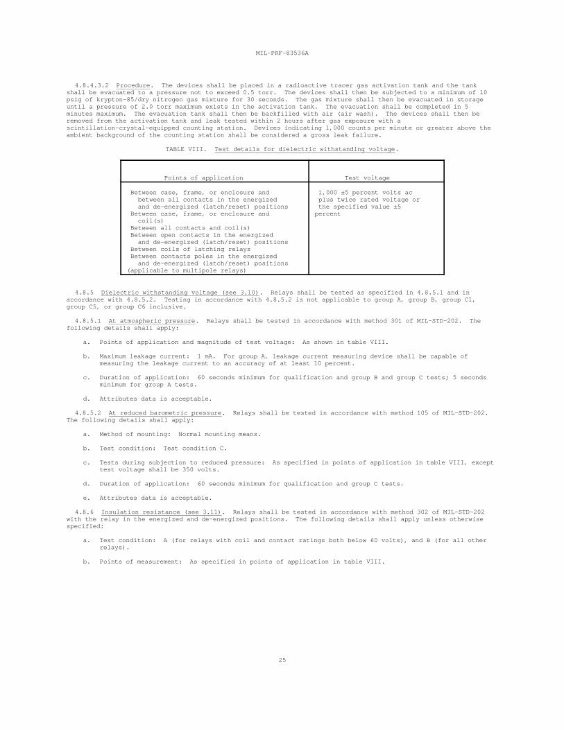
TABLE VIII. Test details for dielectric withstanding voltage.
Points of application Test voltage
Between case, frame, or enclosure and 1,000 ±5 percent volts ac between all contacts in the energized plus twice rated voltage or and de-energized (latch/reset) positions the specified value ±5 Between case, frame, or enclosure and percent coil(s) Between all contacts and coil(s) Between open contacts in the energized and de-energized (latch/reset) positions Between coils of latching relays Between contacts poles in the energized and de-energized (latch/reset) positions (applicable to multipole relays)
4.8.5 Dielectric withstanding voltage (see 3.10). Relays shall be tested as specified in 4.8.5.1 and inaccordance with 4.8.5.2. Testing in accordance with 4.8.5.2 is not applicable to group A, group B, group C1,group C5, or group C6 inclusive.
4.8.5.1 At atmospheric pressure. Relays shall be tested in accordance with method 301 of MIL-STD-202. Thefollowing details shall apply:
a. Points of application and magnitude of test voltage: As shown in table VIII.
b. Maximum leakage current: 1 mA. For group A, leakage current measuring device shall be capable ofmeasuring the leakage current to an accuracy of at least 10 percent.
c. Duration of application: 60 seconds minimum for qualification and group B and group C tests; 5 secondsminimum for group A tests.
d. Attributes data is acceptable.
4.8.5.2 At reduced barometric pressure. Relays shall be tested in accordance with method 105 of MIL-STD-202. The following details shall apply:
a. Method of mounting: Normal mounting means.
b. Test condition: Test condition C.
c. Tests during subjection to reduced pressure: As specified in points of application in table VIII, excepttest voltage shall be 350 volts.
d. Duration of application: 60 seconds minimum for qualification and group C tests.
e. Attributes data is acceptable.
4.8.6 Insulation resistance (see 3.11). Relays shall be tested in accordance with method 302 of MIL-STD-202with the relay in the energized and de-energized positions. The following details shall apply unless otherwisespecified:
a. Test condition: A (for relays with coil and contact ratings both below 60 volts), and B (for all otherrelays).
b. Points of measurement: As specified in points of application in table VIII.
MIL-PRF-83536A
26
4.8.7 Electrical characteristics (see 3.12).
4.8.7.1 Coil resistance (see 3.12.1). Relay coils shall be tested in accordance with method 303 of MIL-STD-202(see 6.9 for optional temperature conversion formula).
4.8.7.2 Maximum coil current (see 3.12.2). When rated voltage is applied to the coil terminals, the currentmust be within the limits as specified (see 3.1). Apply rated voltage for 5 seconds maximum.
4.8.7.3 Static contact resistance and contact voltage drop (see 3.12.3).
4.8.7.3.1 Static contact resistance. Relays shall be tested in accordance with method 307 of MIL-STD-202. Thefollowing details and exceptions shall apply:
a. Method of connection: Connection jigs or other suitable means.
b. Test load: 10 mA maximum at 6 V maximum (dc or peak ac). Post test loads for high level life andintermediate current: Current and voltage shall be the same as the life (for group B tests) orintermediate current (for group C1 tests) or 100 mA at 28 volts dc maximum.
c. Number of actuations prior to measurement: None.
d. Number of test activations: Three.
e. Number of measurements per activation: One in each closed contact position.
f. Points of measurements:
(1) Between all normally closed mated contacts.
(2) Between all normally open mated contacts, with the coil energized with rated coil voltage (orcurrent).
4.8.7.3.2 Contact voltage drop. Relays shall be tested in accordance with method 307 of MIL-STD-202. Thefollowing details and exceptions shall apply:
a. Method of connection: Connection jigs or other suitable means.
b. Test load: Rated resistive at 6 V maximum (dc or peak ac). Contacts shall not make or break this load.
c. Number of actuations prior to measurement: None.
d. Number of test activations: Ten. For group A, group B, group C1, and group C5, one reading per contactshall be used.
e. Number of measurements per activation: One in each closed contact positions. Unless otherwise specified(see 3.1), the contact voltage drop shall be measured within 2 seconds maximum.
f. Points of measurements:
(1) Between all normally closed mated contacts.
(2) Between all normally open mated contacts, with the coil energized with rated coil voltage (orcurrent).
g. Post test loads for high level life and intermediate current: Current and voltage shall be the same asthe life (for group B tests) or intermediate current (for group C1 tests) or 100 mA at 28 volts dcmaximum.
4.8.7.4 Specified pickup or latch/reset, hold, and dropout values (voltages) (see 3.12.4). Specified pickup orlatch/reset, hold, and dropout values (voltage) shall be measured as specified in 4.8.7.4.1, 4.8.7.4.2, 4.8.7.4.3,or 4.8.7.4.4. For qualification inspection, the relay shall be mounted in each of three mutually perpendicularplanes unless otherwise specified (see 3.1). For quality conformance inspection, the relay mounting position isoptional. A suitable indicating device shall be used to monitor contact position. During the test all contactsshall not change state (break or remake) when the coil is energized at or above the specified pickup orlatch/reset value (voltage); when the coil voltage is lowered to any value at or above specified hold value(voltage); or when the coil voltage is reduced from the specified dropout value (voltage) to zero. It ispermissible to perform specified pickup or latch/reset, hold, and dropout values (voltages) using step functionvoltage changes as specified in 4.8.7.4.1 or 4.8.7.4.2, 4.8.7.4.3, and 4.8.7.4.4. Due to the fact that slowramping will overheat relay coils and vary specified pickup or latch/reset, hold, and dropout values (voltages),the step function method shall be the governing method in cases of dispute. For qualification, and group Cinspections testing, specified pickup or latch/reset, hold, and dropout values (voltages) shall be measured atminimum, ambient, and maximum temperatures specified (see 3.1). Following group B, group C1, group C3, and groupC4 testing, the over the temperature range values for specified pickup, hold, and dropout shall apply at ambienttemperature.
4.8.7.4.1 Specified pickup value (voltage) (not applicable to latching relays). The voltage shall be increasedfrom zero until the relay operates, and the specified pickup value (voltage) shall be measured. It ispermissible to perform specified pickup value (voltage) using a step function voltage change as follows and asillustrated on figure 5. In addition to step function changes in voltage levels as depicted on figure 5, rapid
MIL-PRF-83536A
27
voltage ramps, rapidly increasing small incremental steps and combination of step functions and ramps may be usedto achieve the specified pickup, hold, and dropout values (voltages) sequencing.
a. Step up to the specified pickup value (voltage), contacts shall have transferred and all normally opencontacts shall be made.
b. Apply rated coil voltage.
c. Step down to specified hold value (voltage). Normally open contacts shall still be making.
d. Step down to specified dropout value (voltage). All contacts shall have transferred and all normallyclosed contacts shall be making.
e. Step down to zero voltage.
4.8.7.4.2 Specified latch/reset value (voltage) (applicable to latching relays only). Before measuring thespecified pickup value (voltage), establish that all contacts are in their last energized mode for latching relays(see 3.1). If not, apply rated voltage to establish last energized position. Gradually increase the voltage tothe latching coil until the contacts transfer and the specified operate (latch) value (voltage) shall be measured. Apply rated latching voltage and reduce to zero. Gradually increase the voltage to the reset coil until thecontacts transfer and the specified pickup (reset) value (voltage) shall be measured. It is permissible toperform maximum pickup (latch/reset) value (voltage) using a step function as follows and as illustrated on figure5.
a. Step up to specified latch value (voltage) for latching relay. The contacts shall have transferred tothe latch position.
b. Step up to rated voltage and then stepdown to zero.
c. Step up to specified reset value (voltage) for latching relays. The contacts shall have transferred toreset position.
d. Step up to rated voltage and then stepdown to zero.
4.8.7.4.3 Specified hold value (voltage) (not applicable to latching relays). Rated voltage shall be appliedto the coil. The voltage shall then be reduced to the specified hold value (voltage) (see 3.1 and 6.10). Allcontacts shall not change state. It is permissible to perform this test using the step function voltage programdescribed in 4.8.7.4.1 and on figure 5.
4.8.7.4.4 Specified dropout value (voltage) (not applicable to latching relays). Rated voltage shall beapplied to the coil. The voltage shall then be gradually reduced until all contacts return to the de-energizedposition and the specified dropout value (voltage) shall be measured. It is permissible to perform this testusing the step function voltage program described in 4.8.7.4.1 and on figure 5.
4.8.7.5 Operate and release time (see 3.12.5). Operate and release time shall be measured using anoscilloscope or other acceptable means approved by the qualifying activity. Rated voltage shall be applied to thecoil. Contact load conditions shall be 6 V dc maximum or peak ac at 10 mA maximum. The circuit shown on figure6, or equivalent, shall be used. The operate and release time shall be exclusive of contact bounce or contactstabilization time. Timing measurements shall be made on all contact sets. Release time is not applicable tolatching relays. Electronic instrumentation or other suitable means may be used for group A inspection. Determination of compliance to the simultaneously switching requirement shall be made, by comparing the highesttime to the lowest time of the poles as measured for operate and release time. The procedure for measurementshall be approved by the qualifying activity.
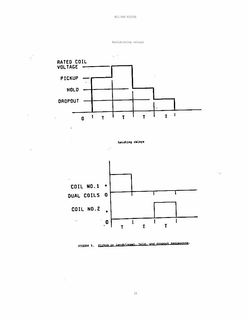
MIL-PRF-83536A
Nonlatching relays
28
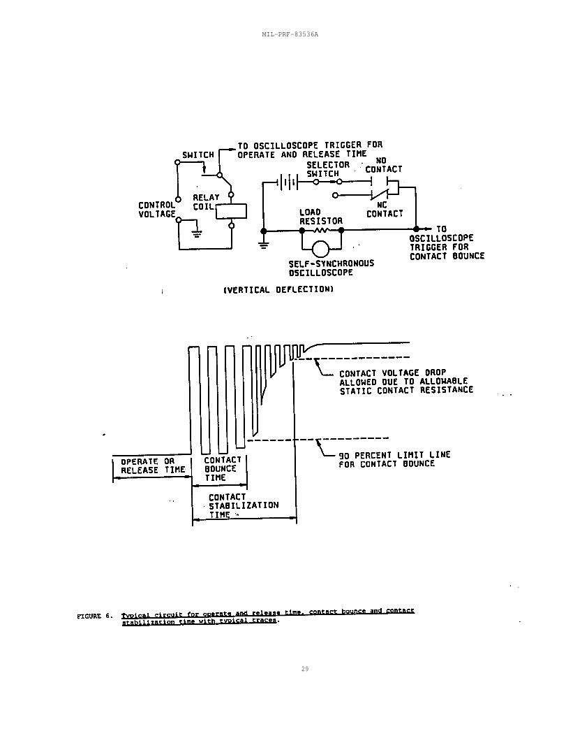
MIL-PRF-83536A
29
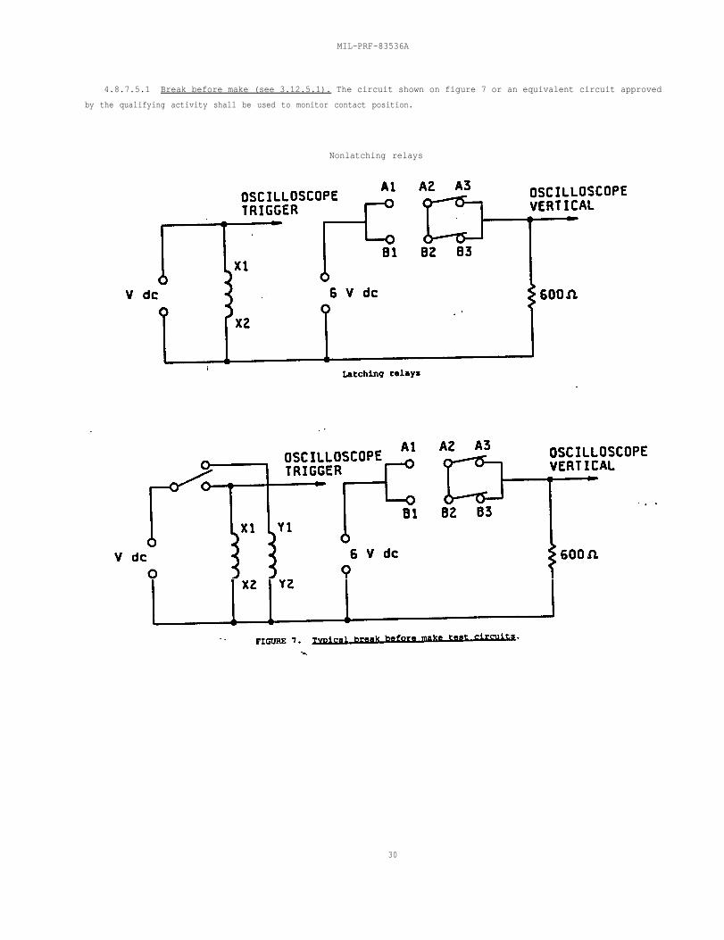
MIL-PRF-83536A
4.8.7.5.1 Break before make (see 3.12.5.1). The circuit shown on figure 7 or an equivalent circuit approved
by the qualifying activity shall be used to monitor contact position.
Nonlatching relays
30
MIL-PRF-83536A
31
4.8.7.6 Contact dynamic characteristics (see 3.12.6).
4.8.7.6.1 Contact bounce (see 3.12.6.1). Contact bounce shall be measured on each contact set using anoscilloscope or other acceptable means approved by the qualifying activity. The trace shall show contactswitching at operate and release and appropriate timing markers when using an oscilloscope. Rated voltage shallbe applied to the coil. Contacts shall be loaded with 6 V dc maximum or peak ac at 10 mA maximum. After highlevel rated load life and intermediate current tests, contact bounce shall be measured at 100 mA at 28 V dc. Acontact bounce shall be considered any occurrence equal to or greater than 90 percent of the open circuit voltagewith a pulse width of 10 µs or greater. The circuit shown on figure 6, or equivalent, shall be used.
4.8.7.6.2 Contact stabilization time (see 3.12.6.2). Contact stabilization time shall be measured on eachcontact set using an oscilloscope or other acceptable means approved by the qualifying activity. The equipmentshall have the capability of indicating a failure pulse width of greater than 1 µs. The trace shall show contactswitching at operate and release, appropriate timing markers, and maximum allowable contact voltage drop markers(which equates to the allowable static contact resistance). Rated voltage shall be applied to the coil. Contactsshall be loaded with 50 mV dc maximum or peak ac at 50 mA maximum. Contact stabilization time shall be defined asthe maximum time allowed for the contacts to reach and maintain a static contact resistance state following theactual operate or release time of the relay (essentially, it is the sum of the contact bounce time (see 6.10) andthe time for the dynamic contact resistance to stabilize to the static contact resistance). The circuit shown onfigure 6, or equivalent, shall be used. After high level rated load life and intermediate current tests, thecontacts shall be loaded at 100 mA at 28 V dc and contact bounce in lieu of contact stabilization time shall bemeasured as specified in 4.8.7.6.1.
4.8.7.7 Coil transient suppression (applicable to dc operated relays with internal coil suppression) (see3.12.7). The coil shall be connected as shown on figure 8 or by an equivalent test circuit and tested asspecified below.
NOTE: Voltage greater than the maximum specified may damage the coil transient suppression device.
a. The switching relay shall be a mercury wetted contact switching relay or a solid state relay without anybuilt-in transient suppression function. E is rated operating voltage for the relay under test. Theswitching relay is operated from a source voltage independent of E. CRO is cathode-ray oscilloscope witha rise time of 20 ns or less. The horizontal (time) deflection scale shall be set at 0.5 millisecond(ms) to 1 ms per division (0.5 ms/cm to 1 ms/cm), and the vertical (voltage) defection to such that thevertical gain provided accuracy in reading. Example: 5 V/cm for a 12 V back EMF limit, or 10 V/cm for a24 V back EMF limit. Both horizontal (time) and vertical (voltage) deflection traces shall be of acalibrated grid spacing (i.e., cm or mm).
b. The source, E, shall be a low impedance source capable of delivering the rated coil voltage with nolimiting resistor or potentiometer used to regulate the line voltage. (Having low source impedancerepresenting a typical application is more important than having the exact rated voltage.)
c. The switching relay shall be closed for a minimum of ten times the operate time of the test relay, orswitching relay whichever is longer, to allow the oscilloscope and circuit network to stabilize and thenopened to obtain the induced voltage deflection trace. Relay shall be cycled at 10 Hz ±2 Hz withapproximately equal open and closed times.
(1) The reading shall be observed on the oscilloscope or other equivalent electronic testinstrumentation. The magnitude of the induced voltage transient shall be noted. A typical trace ispresented on figure 9.
(2) The maximum value of three consecutive readings shall be noted.
(3) Unless otherwise specified, the temperature at the time of the testing shall be +25 C ±5 C.
d. For group A testing, only one measurement and other suitable tests methods may be used to verify that theback EMF (coil kick) is within the specified limit.
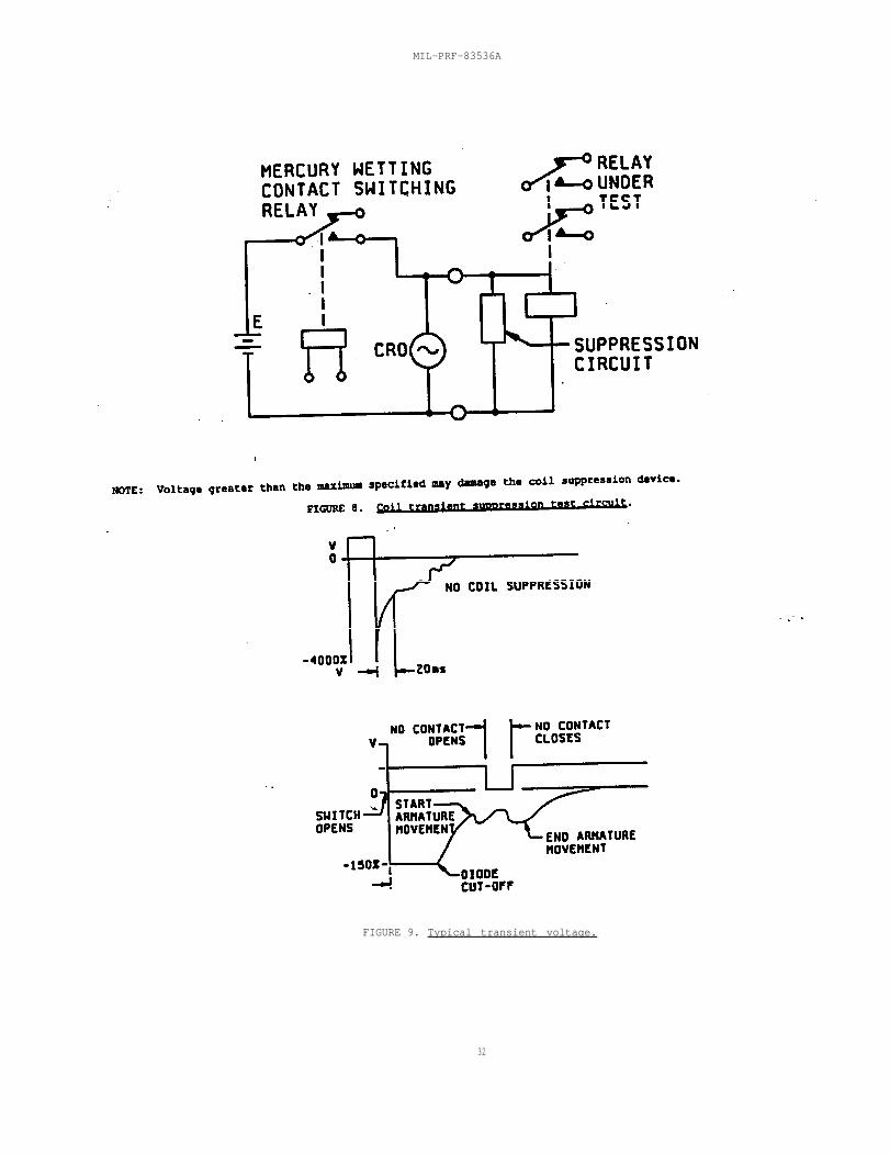
MIL-PRF-83536A
32
FIGURE 9. Typical transient voltage.
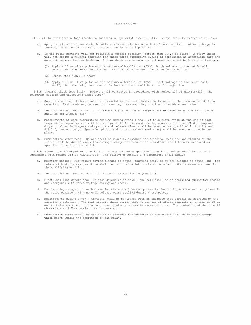
MIL-PRF-83536A
33
4.8.7.8 Neutral screen (applicable to latching relays only) (see 3.12.8). Relays shall be tested as follows:
a. Apply rated coil voltage to both coils simultaneously for a period of 10 ms minimum. After voltage isremoved, determine if the relay contacts are in neutral position.
b. If the relay contacts will not maintain a neutral position, repeat step 4.8.7.8a twice. A relay whichwill not assume a neutral position for these three successive cycles is considered an acceptable part anddoes not require further testing. Relays which remain in a neutral position shall be tested as follows:
(1) Apply a 10 ms ±1 ms pulse of the maximum allowable (at +25 C) latch voltage to the latch coil. Verify that the relay has latched. Failure to latch shall be cause for rejection.
(2) Repeat step 4.8.7.8a above.
(3) Apply a 10 ms ±1 ms pulse of the maximum allowable (at +25 C) reset voltage to the reset coil. Verify that the relay has reset. Failure to reset shall be cause for rejection.
4.8.8 Thermal shock (see 3.13). Relays shall be tested in accordance with method 107 of MIL-STD-202. Thefollowing details and exceptions shall apply:
a. Special mounting: Relays shall be suspended in the test chamber by twine, or other nonheat conductingmaterial. Test leads may be used for mounting; however, they shall not provide a heat sink.
b. Test condition: Test condition B, except exposure time at temperature extreme during the fifth cycleshall be for 2 hours each.
c. Measurements at each temperature extreme during steps 1 and 3 of this fifth cycle at the end of eachtemperature exposure, and with the relays still in the conditioning chamber, the specified pickup anddropout values (voltages) and operate and release time, shall be measured as specified in 4.8.7.4 and4.8.7.5, respectively. Specified pickup and dropout values (voltages) shall be measured in only oneplane.
d. Examination after test: Relays shall be visually examined for cracking, peeling, and flaking of thefinish, and the dielectric withstanding voltage and insulation resistance shall then be measured asspecified in 4.8.5.1 and 4.8.6.
4.8.9 Shock (specified pulse) (see 3.14). Unless otherwise specified (see 3.1), relays shall be tested inaccordance with method 213 of MIL-STD-202. The following details and exceptions shall apply:
a. Mounting method: For relays having flanges or studs, mounting shall be by the flanges or studs; and forrelays without flanges, mounting shall be by plugging into sockets, or other suitable means approved bythe qualifying activity.
b. Test condition: Test condition A, B, or C, as applicable (see 3.1).
c. Electrical load conditions: In each direction of shock, the coil shall be de-energized during two shocksand energized with rated voltage during one shock.
d. For latching relays: In each direction there shall be two pulses in the latch position and two pulses inthe reset position, with no coil voltage being applied during these pulses.
e. Measurements during shock: Contacts shall be monitored with an adequate test circuit as approved by thequalifying activity. The test circuit shall verify that no opening of closed contacts in excess of 10 µsand no false closure or bridging of open contacts occurs in excess of 1 µs. The contact load shall be 10mA maximum at 6 V dc maximum (dc or peak ac).
f. Examination after test: Relays shall be examined for evidence of structural failure or other damagewhich might impair the operation of the relay.
MIL-PRF-83536A
34
4.8.10 Vibration (see 3.15).
4.8.10.1 Vibration (sinusoidal). Unless otherwise specified (see 3.1), relays shall be tested in accordancewith method 204 of MIL-STD-202. The following details and exceptions shall apply:
a. Mounting method: As specified in 4.8.9a.
b. Electrical load conditions: For qualification and group C inspections, relays shall be tested with thecoil energized for 2 hours at rated voltage and with the coil de-energized for 2 hours, in each of thethree mutually perpendicular (x, y, and z) axes (for latching relays, relays shall be tested with thecoils de-energized; 2 hours with the latch coil last energized and 2 hours with the reset coil lastenergized in each of the 3 mutually perpendicular relay axes).
c. Test condition: Test condition D, except vibration level is the lesser of 0.195 inch (4.95 mm) doubleamplitude or 30 G, and frequency range is 10 Hz to 3,000 Hz unless otherwise specified (see 3.1).
d. Tests during vibration: As specified in 4.8.9e.
e. Examination after test: Prior to removal from test fixture and without disturbing the relay, applymaximum over the temperature range pickup voltage value (see 3.1) to the coil and verify that relaycontacts transfer. Remove coil voltage and verify that relay contacts transfer. Failure of relaycontacts to transfer shall be cause for rejection. After removal from test fixture, the relays shallthen be inspected for evidence of structural failure or other damage which might impair the operation ofthe relay.
f. Unless otherwise specified (see 3.1), for group A testing, only one cycle shall be performed over thefrequency range of 100 Hz to 3,000 Hz unless otherwise specified (see 3.1). The relay shall be vibratedin the direction of contact motion. At the option of the manufacturer, the relay production lot may bedivided in three equal groups and each group shall be tested in one of three mutually perpendicular axes(x, y, and z). When relays are tested as specified in the optional procedure, a failure of any relay inany axis shall require 100 percent inspection of all relays in the production lot in each axis. Thecycle shall consist of 3 minutes up with the coil energized with rated voltage and 3 minutes down withcoil de-energized. Latching relays shall remain in each latched position with no voltage applied to thecoils 3 minutes in the latch position and 3 minutes in the reset position.
4.8.10.2 Vibration (random). Unless otherwise specified, relays shall be tested in accordance with method 214of MIL-STD-202. The following details and exceptions shall apply:
a. Mounting method: As specified in 4.8.9a.
b. Electrical load conditions: Relays shall be tested with the coil energized at rated voltage for 7.5minutes and with the coil de-energized for 7.5 minutes, in each of three mutually perpendicular (x,y, andz) axes. Latching relays shall be tested with the coils de-energized; 7.5 minutes with the latch coillast energized and 7.5 minutes with the reset coil last energized. When applicable to group Ainspection, the test time shall be 3 minutes for each state described above.
c. Test condition: Test condition IG (0.4 G /Hz, 23.1 rms G) unless otherwise specified (see 3.1).2
d. Tests during vibration: As specified in 4.8.9e.
e. Examination after test: As specified in 4.8.10.1e.
4.8.11 Acceleration (unless otherwise specified, see 3.1 and 3.16). Relays shall be tested in accordance withmethod 212 of MIL-STD-202. The following detail and exceptions shall apply:
a. Mounting method: As specified in 4.8.9a.
b. Test conditions: Test condition A, 30 G's, unless otherwise specified (see 3.1). (Acceleration shall beapplied in each direction along three mutually perpendicular axes of the specimen. One axis shall be inthe direction most likely to cause malfunction.) In each direction, the coil shall be de-energized for 5minutes, rated coil voltage shall be momentarily applied; and the voltage shall be reduced to the maximumambient pickup voltage as specified (see 3.1) for 5 minutes. Latching relays shall remain in eachlatched position with no voltage applied to the coils. Contacts shall be monitored for proper position.
c. Examination after test: As specified in 4.8.9f.
4.8.12 Terminal strength (see 3.17). Relays shall be tested in accordance with method 211 of MIL-STD-202 inaccordance with the following, as specified in 3.1. Unless otherwise specified herein, two terminals of eachdiscrete design, size, and configuration shall be tested; however, if there is only one of such design, size, andconfiguration, it shall be tested.
4.8.12.1 Pull test (all terminal types). Terminals shall be tested as specified in test condition A, the forceshall be as specified (see 3.1).
4.8.12.2 Bend test (all terminal types). Each terminal shall be bent 20 degrees to 30 degrees in bothdirections from the normal axis in a given plane and after returning it to normal, the terminal shall be bent 20degrees to 30 degrees in both directions perpendicular to the previous plane. The terminals shall be returned totheir normal positions. Following the bend test, the applicable pull force specified in table IX shall be appliedto each terminal for a period of 15 seconds to 30 seconds.
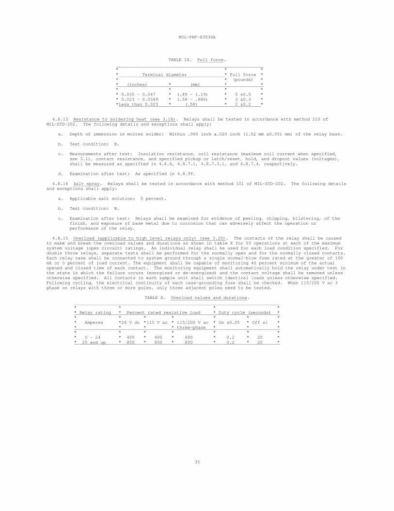
MIL-PRF-83536A
35
TABLE IX. Pull force.
* * ** Terminal diameter * Pull force ** * (pounds) ** (inches) * (mm) * ** * * ** 0.035 - 0.047 * (.89 - 1.19) * 5 ±0.5 ** 0.023 - 0.0349 * (.58 - .886) * 3 ±0.3 **Less than 0.023 * (.58) * 2 ±0.2 *
4.8.13 Resistance to soldering heat (see 3.18). Relays shall be tested in accordance with method 210 ofMIL-STD-202. The following details and exceptions shall apply:
a. Depth of immersion in molten solder: Within .060 inch ±.020 inch (1.52 mm ±0.051 mm) of the relay base.
b. Test condition: B.
c. Measurements after test: Insulation resistance, coil resistance (maximum coil current when specified,see 3.1), contact resistance, and specified pickup or latch/reset, hold, and dropout values (voltages),shall be measured as specified in 4.8.6, 4.8.7.1, 4.8.7.3.1, and 4.8.7.4, respectively.
d. Examination after test: As specified in 4.8.9f.
4.8.14 Salt spray. Relays shall be tested in accordance with method 101 of MIL-STD-202. The following detailsand exceptions shall apply:
a. Applicable salt solution: 5 percent.
b. Test condition: B.
c. Examination after test: Relays shall be examined for evidence of peeling, chipping, blistering, of thefinish, and exposure of base metal due to corrosion that can adversely affect the operation orperformance of the relay.
4.8.15 Overload (applicable to high level relays only) (see 3.20). The contacts of the relay shall be causedto make and break the overload values and durations as shown in table X for 50 operations at each of the maximumsystem voltage (open circuit) ratings. An individual relay shall be used for each load condition specified. Fordouble throw relays, separate tests shall be performed for the normally open and for the normally closed contacts. Each relay case shall be connected to system ground through a single normal-blow fuse rated at the greater of 100mA or 5 percent of load current. The equipment shall be capable of monitoring 40 percent minimum of the actualopened and closed time of each contact. The monitoring equipment shall automatically hold the relay under test inthe state in which the failure occurs (energized or de-energized) and the contact voltage shall be removed unlessotherwise specified. All contacts in each sample unit shall switch identical loads unless otherwise specified. Following cycling, the electrical continuity of each case-grounding fuse shall be checked. When 115/200 V ac 3phase on relays with three or more poles, only three adjacent poles need to be tested.
TABLE X. Overload values and durations.
* * * ** Relay rating * Percent rated resistive load * Duty cycle (seconds) ** * * * * * ** Amperes *28 V dc *115 V ac * 115/200 V ac * On ±0.05 * Off ±1 ** * * * three-phase * * ** * * * * * ** 0 - 24 * 400 * 400 * 600 * 0.2 * 20 ** 25 and up * 800 * 800 * 800 * 0.2 * 20 *
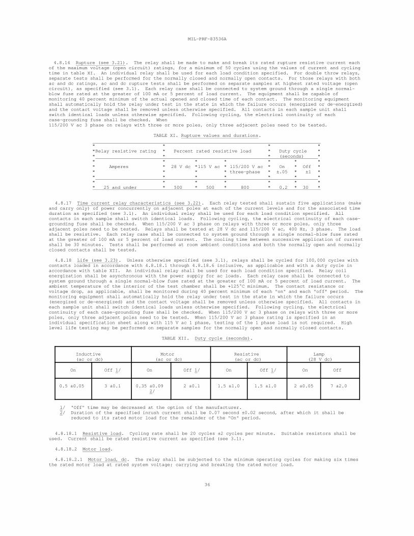
MIL-PRF-83536A
36
4.8.16 Rupture (see 3.21). The relay shall be made to make and break its rated rupture resistive current eachof the maximum voltage (open circuit) ratings, for a minimum of 50 cycles using the values of current and cyclingtime in table XI. An individual relay shall be used for each load condition specified. For double throw relays,separate tests shall be performed for the normally closed and normally open contacts. For those relays with bothac and dc ratings, ac and dc rupture tests shall be performed on separate samples at highest rated voltage (opencircuit), as specified (see 3.1). Each relay case shall be connected to system ground through a single normal-blow fuse rated at the greater of 100 mA or 5 percent of load current. The equipment shall be capable ofmonitoring 40 percent minimum of the actual opened and closed time of each contact. The monitoring equipmentshall automatically hold the relay under test in the state in which the failure occurs (energized or de-energized)and the contact voltage shall be removed unless otherwise specified. All contacts in each sample unit shallswitch identical loads unless otherwise specified. Following cycling, the electrical continuity of eachcase-grounding fuse shall be checked. When 115/200 V ac 3 phase on relays with three or more poles, only three adjacent poles need to be tested.
TABLE XI. Rupture values and durations.
* * * **Relay resistive rating * Percent rated resistive load * Duty cycle ** * * (seconds) ** * * * * * ** Amperes * 28 V dc *115 V ac * 115/200 V ac * On * Off ** * * * three-phase * ±.05 * ±1 ** * * * * * ** * * * * * ** 25 and under * 500 * 500 * 800 * 0.2 * 30 *
4.8.17 Time current relay characteristics (see 3.22). Each relay tested shall sustain five applications (makeand carry only) of power concurrently on adjacent poles at each of the current levels and for the associated timeduration as specified (see 3.1). An individual relay shall be used for each load condition specified. Allcontacts in each sample shall switch identical loads. Following cycling, the electrical continuity of each case-grounding fuse shall be checked. When 115/200 V ac 3 phase on relays with three or more poles, only threeadjacent poles need to be tested. Relays shall be tested at 28 V dc and 115/200 V ac, 400 Hz, 3 phase. The loadshall be resistive. Each relay case shall be connected to system ground through a single normal-blow fuse ratedat the greater of 100 mA or 5 percent of load current. The cooling time between successive application of currentshall be 30 minutes. Tests shall be performed at room ambient conditions and both the normally open and normallyclosed contacts shall be tested.
4.8.18 Life (see 3.23). Unless otherwise specified (see 3.1), relays shall be cycled for 100,000 cycles withcontacts loaded in accordance with 4.8.18.1 through 4.8.18.6 inclusive, as applicable and with a duty cycle inaccordance with table XII. An individual relay shall be used for each load condition specified. Relay coilenergization shall be asynchronous with the power supply for ac loads. Each relay case shall be connected tosystem ground through a single normal-blow fuse rated at the greater of 100 mA or 5 percent of load current. Theambient temperature of the interior of the test chamber shall be +125 C minimum. The contact resistance orvoltage drop, as applicable, shall be monitored during 40 percent minimum of each "on" and each "off" period. Themonitoring equipment shall automatically hold the relay under test in the state in which the failure occurs(energized or de-energized) and the contact voltage shall be removed unless otherwise specified. All contacts ineach sample unit shall switch identical loads unless otherwise specified. Following cycling, the electricalcontinuity of each case-grounding fuse shall be checked. When 115/200 V ac 3 phase on relays with three or morepoles, only three adjacent poles need to be tested. When 115/200 V ac 3 phase rating is specified in anindividual specification sheet along with 115 V ac 1 phase, testing of the 1 phase load is not required. Highlevel life testing may be performed on separate samples for the normally open and normally closed contacts.
TABLE XII. Duty cycle (seconds).
Inductive Motor Resistive Lamp (ac or dc) (ac or dc) (ac or dc) (28 V dc)
On Off 1/ On Off 1/ On Off 1/ On Off
0.5 ±0.05 3 ±0.1 0.35 ±0.09 2 ±0.1 1.5 ±1.0 1.5 ±1.0 2 ±0.05 7 ±2.0 2/
1/ "Off" time may be decreased at the option of the manufacturer. 2/ Duration of the specified inrush current shall be 0.07 second ±0.02 second, after which it shall be reduced to its rated motor load for the remainder of the "On" period.
4.8.18.1 Resistive load. Cycling rate shall be 20 cycles ±2 cycles per minute. Suitable resistors shall beused. Current shall be rated resistive current as specified (see 3.1).
4.8.18.2 Motor load.
4.8.18.2.1 Motor load, dc. The relay shall be subjected to the minimum operating cycles for making six timesthe rated motor load at rated system voltage; carrying and breaking the rated motor load.
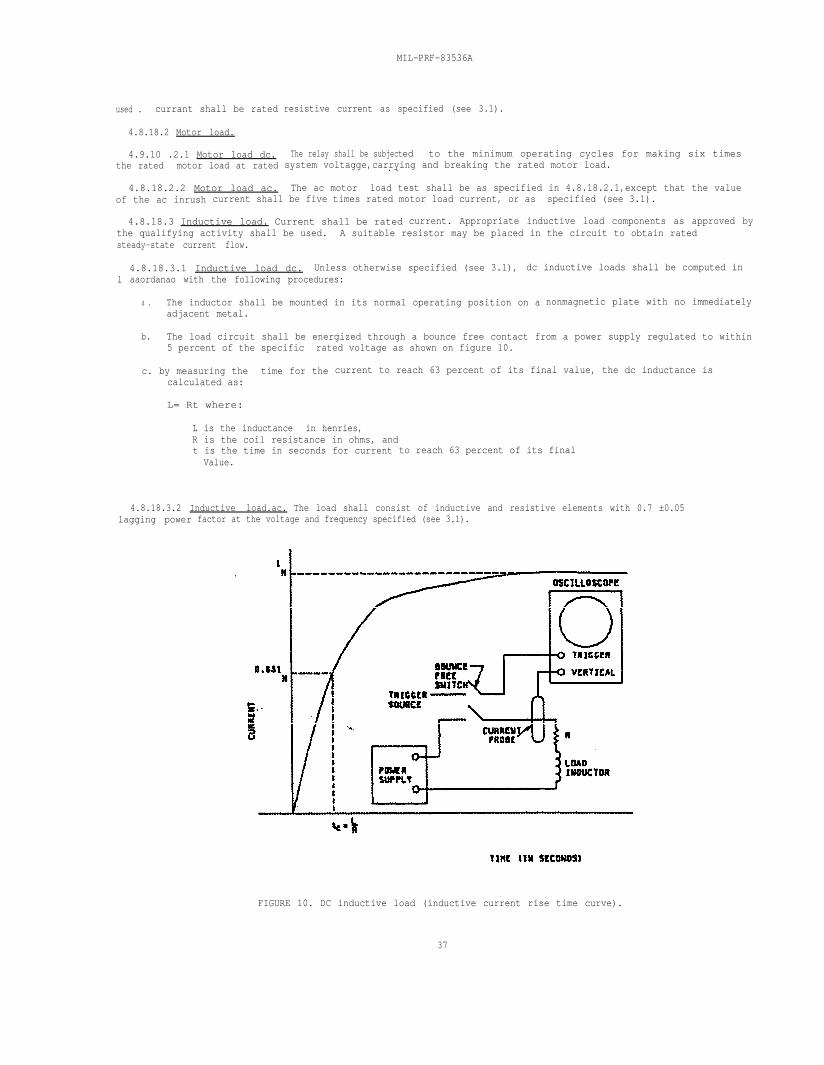
MIL-PRF-83536A
used . currant shall be rated
4.8.18.2 Motor load.
4.9.10 .2.1 Motor load dc.the rated motor load at rated
4.8.18.2.2 Motor load ac.
resistive current as specified (see 3.1).
The relay shall be subjected to the minimum operating cycles for making six timessystem voltagge,carrying and breaking the rated motor load.. .
The ac motor load test shall be as specified in 4.8.18.2.1,except that the valueof the ac inrush current shall be five times rated motor load current, or as specified (see 3.1).
4.8.18.3 Inductive load. Current shall be rated current. Appropriate inductive load components as approved bythe qualifying activity shall be used. A suitable resistor may be placed in the circuit to obtain ratedsteady-state current flow.
4.8.18.3.1 Inductive load dc. Unless otherwise specified (see 3.1), dc inductive loads shall be computed inl aaordanao with the following procedures:
a . The inductor shall be mounted in its normal operating position on a nonmagnetic plate with no immediatelyadjacent metal.
b. The load circuit shall be energized through a bounce free contact from a power supply regulated to within5 percent of the specific rated voltage as shown on figure 10.
c. by measuring the time for the current to reach 63 percent of its final value, the dc inductance iscalculated as:
L= Rt where:
L is the inductance in henries,R is the coil resistance in ohms, and
4.8.18.3.2 Inductive load.ac. The load shall consist of inductive and resistive elements with 0.7 ±0.05 lagging power
t is the time in seconds for currentValue.
factor at the voltage and frequency specified (see 3.1).
to reach 63 percent of its final
FIGURE 10. DC inductive load (inductive current rise time curve).
37
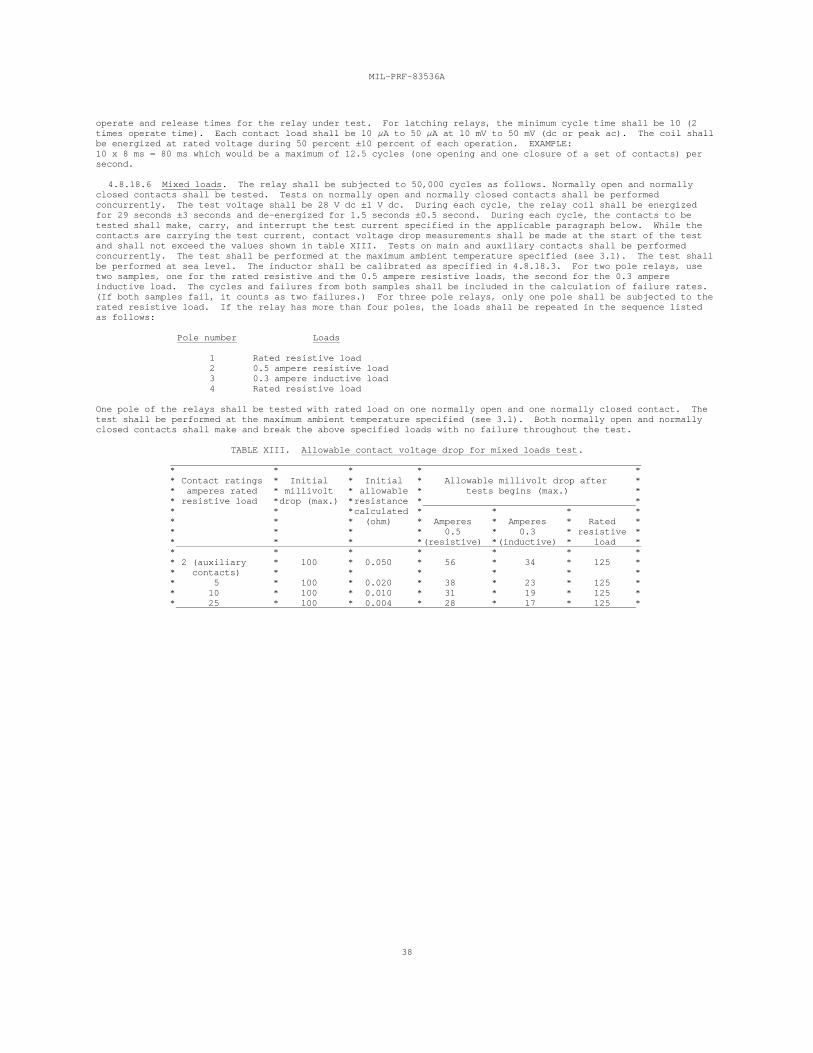
MIL-PRF-83536A
38
operate and release times for the relay under test. For latching relays, the minimum cycle time shall be 10 (2times operate time). Each contact load shall be 10 A to 50 A at 10 mV to 50 mV (dc or peak ac). The coil shallbe energized at rated voltage during 50 percent ±10 percent of each operation. EXAMPLE: 10 x 8 ms = 80 ms which would be a maximum of 12.5 cycles (one opening and one closure of a set of contacts) persecond.
4.8.18.6 Mixed loads. The relay shall be subjected to 50,000 cycles as follows. Normally open and normallyclosed contacts shall be tested. Tests on normally open and normally closed contacts shall be performedconcurrently. The test voltage shall be 28 V dc ±1 V dc. During each cycle, the relay coil shall be energizedfor 29 seconds ±3 seconds and de-energized for 1.5 seconds ±0.5 second. During each cycle, the contacts to betested shall make, carry, and interrupt the test current specified in the applicable paragraph below. While thecontacts are carrying the test current, contact voltage drop measurements shall be made at the start of the testand shall not exceed the values shown in table XIII. Tests on main and auxiliary contacts shall be performedconcurrently. The test shall be performed at the maximum ambient temperature specified (see 3.1). The test shallbe performed at sea level. The inductor shall be calibrated as specified in 4.8.18.3. For two pole relays, usetwo samples, one for the rated resistive and the 0.5 ampere resistive loads, the second for the 0.3 ampereinductive load. The cycles and failures from both samples shall be included in the calculation of failure rates. (If both samples fail, it counts as two failures.) For three pole relays, only one pole shall be subjected to therated resistive load. If the relay has more than four poles, the loads shall be repeated in the sequence listedas follows:
Pole number Loads
1 Rated resistive load 2 0.5 ampere resistive load 3 0.3 ampere inductive load 4 Rated resistive load
One pole of the relays shall be tested with rated load on one normally open and one normally closed contact. Thetest shall be performed at the maximum ambient temperature specified (see 3.1). Both normally open and normallyclosed contacts shall make and break the above specified loads with no failure throughout the test.
TABLE XIII. Allowable contact voltage drop for mixed loads test.
* * * * ** Contact ratings * Initial * Initial * Allowable millivolt drop after ** amperes rated * millivolt * allowable * tests begins (max.) ** resistive load *drop (max.) *resistance * ** * *calculated * * * ** * * (ohm) * Amperes * Amperes * Rated ** * * * 0.5 * 0.3 * resistive ** * * *(resistive) *(inductive) * load ** * * * * * ** 2 (auxiliary * 100 * 0.050 * 56 * 34 * 125 ** contacts) * * * * * ** 5 * 100 * 0.020 * 38 * 23 * 125 ** 10 * 100 * 0.010 * 31 * 19 * 125 ** 25 * 100 * 0.004 * 28 * 17 * 125 *
MIL-PRF-83536A
39
4.8.19 Intermediate current (see 3.24). Intermediate current shall not be considered a low level or high levelcontact load rating (see 6.1.1). Intermediate current life cycles shall not be used for FR determination ormaintenance. Relays shall be tested as specified in method 312 of MIL-STD-202. The following details andexceptions shall apply:
a. Maximum contact resistance: As specified in 3.24.
b. Coil energizing voltage: Rated voltage (see 3.1).
c. Cycling rate: 10 cycles ±2 cycles per minute with minimum of 75 percent coil "ON" time. For latchingrelays, the relay shall be in each position for approximately one-half the cycle time. Each coil shallbe energized for a minimum of 75 percent of each operation.
d. Contact current/voltage: 100 mA at 28 V dc.
e. Monitoring: At least 40 percent of the closed time of each contact during each cycle shall be monitoredfor contact resistance.
f. Number of cycles: 50,000 cycles.
g. Ambient temperature: +125 C minimum.
4.8.20 Mechanical life (see 3.25). Relays shall be cycled 300,000 cycles at room ambient temperature. Thecycling rate shall be as specified in 4.8.18.5. Each contact load shall be 10 A to 50 A at 10 mV to 50 mV (dcor peak ac). The coil shall be energized at rated voltage during 50 percent ±10 percent of each cycle. Mechanical life cycles shall not be used for FR determination or maintenance.
4.8.21 Resistance to solvents (see 3.26). Relays shall be tested in accordance with method 215 of MIL-STD-202except temperature of solvents a, b, and d shall be maintained at +63 C to +70 C. The following details andexceptions shall apply:
a. Portion to be brushed: All marking.
b. Optional procedure for solvent d is not applicable.
c. Specimens to be tested: One sample shall be tested with each solvent solution. For qualificationinspection, samples in excess of the available number of solvents shall be exempt from test. For group Ctesting, two additional samples shall be selected. The additional samples may be electrical rejects fromgroup A2.
d. Examination after test: Specimens shall be examined for legibility of marking.
4.8.22 Continuous current (see 3.27). This test shall be performed at the maximum temperature and altitudespecified. Other conditions of the test shall be in accordance with 4.8.18. During the first 3 hours of thistest, the relay coil shall not be energized. Normally closed contacts shall be loaded with the highest ratedresistive load. At the end of the 3 hour period with no change in the ambient conditions, the pickup voltage ofthe relays shall be determined and shall be within the limit specified. During the next portion of the test, therelay shall be energized continuously for 97 hours. The coil voltage shall be the maximum specified. Contactsthat are in the closed position when the relay coil is energized shall carry the rated resistive current at anyconvenient voltage. Immediately following the operating period and with the relay still at the specifiedtemperature, the relay shall be tested to determine that the energized function is completed when pickup voltageis applied. The relay shall sustain no visible damage such as loosening of terminals or loss of seal. Terminaltemperature rise shall be monitored throughout the test and shall not exceed +75 C.
4.8.23 Internal moisture (see 3.28). The relays shall be energized at rated coil voltage or current andstabilized at the maximum rated temperature specified (see 3.1). The relays shall then be held for 1 hour minimumwith the coils energized at rated voltage or current for nonlatching relays; for latching relays, one coil shallbe energized for 30 minutes minimum, then the other coil shall be energized for 30 minutes minimum. After 1 hourminimum the coil voltage or current shall be increased to 140 percent of rated coil voltage or current for 2minutes minimum for nonlatching relays and 2 minutes minimum for each coil of latching relays. After 2 minutes,the coil voltage or current shall be removed and the relays immediately transferred to a thermal chamberstabilized (prior to opening of the chamber) at the minimum rated temperature specified (see 3.1). The transferbetween chambers shall be accomplished in 5 minutes maximum. Immediately energize the coils with rated voltage orcurrent and maintain the relays at the minimum rated temperature after the chamber has restabilized for a periodof 1 hour minimum for nonlatching relays; for latching relays, one coil shall be energized for 30 minutes minimum,then the other coil shall be energized for 30 minutes minimum. After 1 hour minimum remove the coil voltage orcurrent (for non-latching relays), or remove the coil voltage or current and reapply to opposite coil (forlatching relays), and within 5 seconds of contact closure measure the contact resistance. The contact load shallbe 10 mA to 50 mA at 10 mV dc to 50 mV dc. The contact resistance across the closed contacts shall not exceed 100milliohms. If a relay indicates a failure, and icing of the test socket is suspected to be the cause of failureindication, one complete retest is permitted with the relay mounted in a different socket.
5. PACKAGING
5.1 Packaging. For acquisition purposes, the packaging requirements shall be as specified in the contract ororder (see 6.2). When actual packaging of materiel is to be performed by DoD personnel, these personnel need tocontact the responsible packaging activity to ascertain requisite packaging requirements. Packaging requirementsare maintained by the Inventory Control Point's packaging activity within the Military Department or DefenseAgency, or within the Military Department's System Command. Packaging data retrieval is available from the
MIL-PRF-83536A
40
managing Military Department's or Defense Agency's automated packaging files, CD-ROM products, or by contactingthe responsible packaging activity.
6. NOTES
(This section contains information of a general or explanatory nature which may be helpful, but is notmandatory.)
6.1 Intended use. Relays conforming to this specification are intended for use in electronic and communicationequipment. Their principal areas of application are for aircraft, missiles, spacecraft, and ground-supportelectronic and communication equipment. This does not preclude the use of these relays in other militaryapplications. Consult MIL-STD-1346 for selection and application information.
CAUTION: The use of any coil voltage less than the rated coil voltage will compromise the operation of the relay.
CAUTION: Transfer relay contacts are not to be used to ground load in one position and to 115 volt terminal inother position. Transfer relay contacts are to not be used to transfer load between phases, nor betweenunsynchronized ac sources.
CAUTION: When latching relays are installed in equipment, the latch and reset coils should not be pulsedsimultaneously. Coils should not be pulsed with less than the nominal coil voltage and the pulse width should bea minimum of three times the specified operate time of the relay. If these conditions are not followed, it ispossible for the relay to be in the magnetically neutral position.
6.1.1 Contact rating. The contact ratings of relays covered by this specification are based on load life testswhich establish the relay capability to switch rated loads. For the purposes of this specification, contact loadratings are defined as follows:
a. Low level: 10 A at 50 mV to 10 mA at 6 V.
b. Intermediate: 10 mA at 6 V to 100 mA at 28 V.
c. High level: Above 100 mA at 28 V.
6.1.2 FR level. FR level (percent per 10,000 cycles) as specified in table I, is based on an average of 10cycles per hour, per application, for 1,000 hours in accordance with MIL-STD-690.
6.1.3 Packaging provisions. The preservation, packing, and marking specified herein are intended for directshipments to the Government. However, at the option of the contractor or when so specified, the packagingprovisions herein are also applicable for the preparation of relays for shipment from the parts contractor to theoriginal equipment manufacturer.
6.2 Acquisition requirements. Acquisition documents must specify the following:
a. Title, number, and date of the specification, the applicable associated specification, and the completePIN (see 1.2).
b. Issue of DoDISS to be cited in the solicitation, and if required, the specific issue of individualdocuments referenced (see 2.1).
c. Levels of preservation and packing required (see 5.1).
d. If special or additional identification marking is required (see 3.29).
e. Marking requirements for FR level (see MIL-STD-690).
f. If the terminals are to be solder dipped (retinned).
MIL-PRF-83536A
41
6.3 Qualification. With respect to products requiring qualification, awards will be made only for productswhich are, at the time of award of contract, qualified for inclusion in the QPL whether or not such products haveactually been so listed by that date. The attention of the contractors is called to these requirements, andmanufacturers are urged to arrange to have the products that they propose to offer to the Federal Governmenttested for qualification in order that they may be eligible to be awarded contracts or orders for the productscovered by this specification. The activity responsible for the QPL is the Electronic Support Flight AFMC, 88LOG/LGME, 4170 Hebble Creek Rd., Bldg. 280, Door 24, WPAFB, OH 45433-5653; however, information pertaining toqualification of products may be obtained from the Defense Electronics Supply Center (DESC), 1507 Wilmington Pike,Dayton, OH 45444. Application for qualification tests are to be be made in accordance with provisions governingqualification SD-6 (see 6.3.1).
6.3.1 Provisions Governing Qualification SD-6. Copies of "Provisions Governing Qualification SD-6" may beobtained upon application to the Standardization Documents Order Desk, Building 4D, 700 Robbins, Philadelphia, PA 19111-5094.
6.3.2 Qualification and maintenance by similarity. This information is for reference only. Refer to theindividual specification sheets for detailed information.
6.3.2.1 Qualification by similarity. The graphic guide shown illustrates the relative complexity of individualspecification sheets within a style group for use in determining qualification inspection (reduced testing)candidate specification sheets. Arrow direction indicates flow towards less complex designs. Asterisk indicatesmost complex design of style group.
*/2 -----> /1 */4 -----> /3 */6 -----> /5 */8 -----> /7 */10 ----> /9 */13 ----> /12 */16 ----> /15 */19 ----> /18 */22 ----> /21 */24 ----> /23 */26 ----> /25
6.3.2.2 Maintenance by similarity. The data accumulated for the style groups listed below may be combined forgroup B and group C inspections maintenance and extension of FR levels in accordance with MIL-STD-690. Testing samples must be representative of production. Maintenance plan is contingent uponqualifying activity approval. Failures exceeding the sampling plan selected (C = number), regardless of thespecific specification sheet affected, affect all other specification sheets within the respective style group.
a. DPDT, low level to 5 amperes: /1, /2.
b. DPDT, low level to 5 amperes, magnetic latch: /3, /4.
c. 4PDT, low level to 5 amperes: /5, /6.
d. 4PDT, low level to 5 amperes, magnetic latch: /7, /8.
e. DPDT, low level to 10 amperes: /9, /10.
f. DPDT, low level to 10 amperes, magnetic latch: /12, /13.
g. 4PDT, low level to 10 amperes: /15, /16.
h. 4PDT, low level to 10 amperes, magnetic latch: /18, /19.
i. 3PDT, low level to 10 amperes: /21, /22.
j. 3PDT, low level to 10 amperes, magnetic latch: /23, /24.
k. 6PDT, low level to 10 amperes: /25, /26.
6.4 Shelf life. Relays conforming to this specification should be designed for a minimum of 7 years shelflife, following which the relays should be satisfactory for intended use without further conditioning.
MIL-PRF-83536A
42
6.5 Sealing. The following procedure is suggested as a guide; however, every effort should be made to utilizethe most effective procedure consistent with the state of the art.
a. Evacuate to less than 200 microns.
b. Heat to maximum rated ambient temperature with continued evacuation (see 3.1).
c. Maintain heat and vacuum for 12 hours or longer, continuing the treatment until a maximum pressure of 80microns is reached.
d. Turn off heaters and maintain pressure for 4 hours.
e. Close evacuation valve and fill chamber with the desired pressurizing gas.
f. Seal relay before removing from chamber.
6.6 Intermetallic contact. The finishing of metallic areas to be placed in intimate contact before assemblypresents a special problem, since intermetallic contact of dissimilar metals results in electrolytic couples whichpromote corrosion through galvanic action. To provide the required corrosion protection, intermetallic couplesare restricted to those permitted by table XIV. Table XIV shows metals and alloys (or plates) by groups whichhave common EMF within 0.05 volt when coupled with a saturated calomel electrode in sea-water at room ambienttemperatures. All members of a group are considered as completely compatible, one with the other. Compatiblecouples between groups have been specified in table XIV based on a potential difference of 0.25 volt maximum. Tosimplify any arithmetic involved, table XIV shows, in addition to EMF against a calomel electrode, a derived"anodic index" with group 1 (gold) as 0 and group 18 (magnesium) as 175. Subtraction of a lower group anodicindex gives the EMF difference in hundredths of a volt.
6.6.1 Groups. Table XIV sets up 18 primary groups. It may be noted that neither the metallurgical similarityor dissimilarity of metals is the parameter for selection of compatible couples. All members within a group,regardless of metallurgical similarity, are considered inherently nonsusceptible to galvanic action, when coupledwith any member within the group; for example, such dissimilar metals as platinum and gold. Similarly, suchbasically dissimilar alloys as austenitic stainless steel, silver-solder, and low brass (all members of group 5)are inherently nonsusceptible when coupled together.
6.6.2 Compatibility graphs. Permissible couple series are shown in table XIV by the graphs at the right. Members of groups connected by lines will form permissible couples. A O indicates the most cathodic member ofeach series, a an anodic member, and the arrow indicates the anodic direction.
6.6.3 Selection of compatible couples. Proper selection of metals in the design of equipment will result infewer intermetallic contact problems. For example, for sheltered exposure, neither silver nor tin requireprotective finishes. However, since silver has an anodic index of 15 and tin-plate 65, the EMF generated as acouple is 0.50 volt, which is not allowable by table XIV. In this case, other metals or plates will be required. It should be noted that, in intermetallic couples, the member with the higher anodic index is anodic to the memberwith the lower anodic index and will be susceptible to corrosion in the presence of an electrolytic medium. Ifthe surface area of the cathodic part is significantly greater than that of the anodic part, the corrosive attackon the contact area of the anodic part may be greatly intensified. Material selection for intermetallic contactparts, therefore, should establish the smaller part as the cathodic member of the couple, whenever practicable.
6.6.4 Plating. When base metals intended for intermetallic contact form couples not allowed by table XIV, theyare to be plated with those metals which will reduce the potential difference to that allowed by table XIV.
6.6.4.1 Tin plated finishes. Use of tin plating is prohibited (see 3.4.1.1a). Use of tin finishes can resultin tin whisker growth. Tin whisker growth can result in adverse effects on the operation of electronic equipmentsystems.
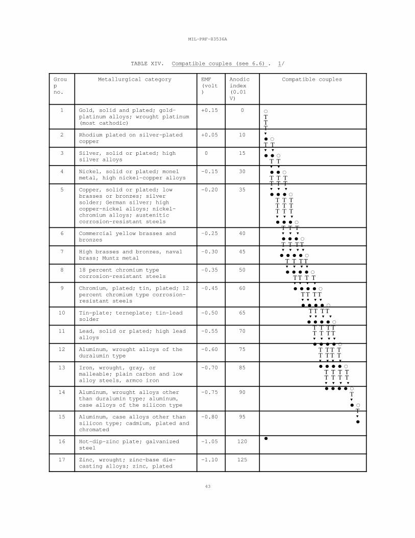
MIL-PRF-83536A
43
TTT
T T
T T T T T T T T T T T T T T T T T T T T T T T T T T T T T T T T T T T T T T T T T T T T T T T T T T T T T T T T T T T T T T T T T T
TABLE XIV. Compatible couples (see 6.6) . 1/
Grou Metallurgical category EMF Anodic Compatible couplesp (volt indexno. ) (0.01
V)
1 Gold, solid and plated; gold- +0.15 0platinum alloys; wrought platinum(most cathodic)
2 Rhodium plated on silver-plated +0.05 10copper
3 Silver, solid or plated; high 0 15silver alloys
4 Nickel, solid or plated; monel -0.15 30metal, high nickel-copper alloys
5 Copper, solid or plated; low -0.20 35brasses or bronzes; silversolder; German silver; highcopper-nickel alloys; nickel-chromium alloys; austeniticcorrosion-resistant steels
6 Commercial yellow brasses and -0.25 40bronzes
7 High brasses and bronzes, naval -0.30 45brass; Muntz metal
8 18 percent chromium type -0.35 50corrosion-resistant steels
9 Chromium, plated; tin, plated; 12 -0.45 60percent chromium type corrosion-resistant steels
10 Tin-plate; terneplate; tin-lead -0.50 65solder
11 Lead, solid or plated; high lead -0.55 70alloys
12 Aluminum, wrought alloys of the -0.60 75duralumin type
13 Iron, wrought, gray, or -0.70 85malleable; plain carbon and lowalloy steels, armco iron
14 Aluminum, wrought alloys other -0.75 90than duralumin type; aluminum,case alloys of the silicon type
15 Aluminum, case alloys other than -0.80 95silicon type; cadmium, plated andchromated
16 Hot-dip-zinc plate; galvanized -1.05 120steel
17 Zinc, wrought; zinc-base die- -1.10 125casting alloys; zinc, plated
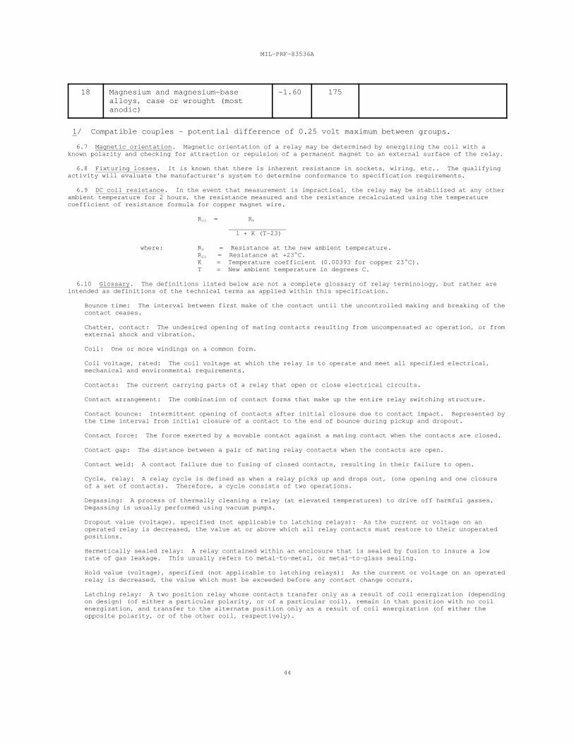
MIL-PRF-83536A
44
18 Magnesium and magnesium-base -1.60 175alloys, case or wrought (mostanodic)
1/ Compatible couples - potential difference of 0.25 volt maximum between groups.
6.7 Magnetic orientation. Magnetic orientation of a relay may be determined by energizing the coil with aknown polarity and checking for attraction or repulsion of a permanent magnet to an external surface of the relay.
6.8 Fixturing losses. It is known that there is inherent resistance in sockets, wiring, etc.. The qualifyingactivity will evaluate the manufacturer's system to determine conformance to specification requirements.
6.9 DC coil resistance. In the event that measurement is impractical, the relay may be stabilized at any otherambient temperature for 2 hours, the resistance measured and the resistance recalculated using the temperaturecoefficient of resistance formula for copper magnet wire.
R = R23 T
1 + K (T-23)
where: R = Resistance at the new ambient temperature.T
R = Resistance at +23 C.23
K = Temperature coefficient (0.00393 for copper 23 C). T = New ambient temperature in degrees C.
6.10 Glossary. The definitions listed below are not a complete glossary of relay terminology, but rather areintended as definitions of the technical terms as applied within this specification.
Bounce time: The interval between first make of the contact until the uncontrolled making and breaking of thecontact ceases.
Chatter, contact: The undesired opening of mating contacts resulting from uncompensated ac operation, or fromexternal shock and vibration.
Coil: One or more windings on a common form.
Coil voltage, rated: The coil voltage at which the relay is to operate and meet all specified electrical,mechanical and environmental requirements.
Contacts: The current carrying parts of a relay that open or close electrical circuits.
Contact arrangement: The combination of contact forms that make up the entire relay switching structure.
Contact bounce: Intermittent opening of contacts after initial closure due to contact impact. Represented bythe time interval from initial closure of a contact to the end of bounce during pickup and dropout.
Contact force: The force exerted by a movable contact against a mating contact when the contacts are closed.
Contact gap: The distance between a pair of mating relay contacts when the contacts are open.
Contact weld: A contact failure due to fusing of closed contacts, resulting in their failure to open.
Cycle, relay: A relay cycle is defined as when a relay picks up and drops out, (one opening and one closureof a set of contacts). Therefore, a cycle consists of two operations.
Degassing: A process of thermally cleaning a relay (at elevated temperatures) to drive off harmful gasses. Degassing is usually performed using vacuum pumps.
Dropout value (voltage), specified (not applicable to latching relays): As the current or voltage on anoperated relay is decreased, the value at or above which all relay contacts must restore to their unoperatedpositions.
Hermetically sealed relay: A relay contained within an enclosure that is sealed by fusion to insure a lowrate of gas leakage. This usually refers to metal-to-metal, or metal-to-glass sealing.
Hold value (voltage), specified (not applicable to latching relays): As the current or voltage on an operatedrelay is decreased, the value which must be exceeded before any contact change occurs.
Latching relay: A two position relay whose contacts transfer only as a result of coil energization (dependingon design) (of either a particular polarity, or of a particular coil), remain in that position with no coilenergization, and transfer to the alternate position only as a result of coil energization (of either theopposite polarity, or of the other coil, respectively).
MIL-PRF-83536A
45
Miss: Failure to establish the intended circuit conditions (high or low output resistance, as applicable).
Normally closed contacts: Those contacts that are closed with the relay de-energized.
Normally open contacts: Those contacts that are open with the relay de-energized.
Operate time: The interval between the application of a step function input signal and closing of allnormally open contacts. Bounce time is not included.
Pickup value (voltage), specified: As the current or voltage on an unoperated relay is increased, the value(voltage) at or below which all contacts must function.
Polarized relay: A relay, the operation of which is primarily dependent upon the direction (polarity) of theenergizing current(s) and the resultant magnetic flux. The opposite of neutral relay. Also called "polarrelay".
Relay: Most simply defined as an electrically controlled device that opens and closes electrical contacts toeffect the operation of other devices in the same or another electrical circuit.
Release time: The interval between the trailing edge of a step function input signal and closing of allnormally closed contacts. Bounce time is not included. Not applicable to latching relays.
Shelf life: A period of time a relay can be stored unused before detrimental changes occur which would causethe item not to properly perform its function within the requirements of this specification.
Silicone: Any of a group of semi-inorganic polymers based on the structural unit R Si0, where R is an2
organic group, characterized by wide range thermal stability, high lubricity, extreme water repellence, andphysiochemical inertness, used in adhesives, lubricants, protective coatings, paints, electrical insulation,synthetic rubber, and prosthetic replacements for bodily parts.
Transfer time: The time interval between the opening of the closed contact and the closing of the opencontact of a break-make-contact combination. For multipole relays, transfer time is defined as the intervalbetween the opening of the last closed contact and the closing of the first open contact of any set.
6.11 Subject term (key word) listing.
AC coilAll weldedCoil transient suppressionElectromagneticEstablished reliabilityHermetically sealedLow level contact ratingMagnetic latch
6.12 Changes from previous issue. Marginal notations are not used in this revision to identify changes withrespect to the previous issue due to the extensiveness of the changes.
CONCLUDING MATERIAL
Custodians: Preparing activity:Army - ER Air Force - 85Navy - ECAir Force - 85 Agent:
DLA - ESReview activities:
Navy - AS (Project number 5945-0950)Air Force - 99NASA - NADLA - ES
STANDARDIZATION DOCUMENT IMPROVEMENT PROPOSAL
INSTRUCTIONS
1. The preparing activity must complete blocks 1, 2, 3, and 8. In block 1, both the document number and revision letter should be given.
2. The submitter of this form must complete blocks 4, 5, 6, and 7.
3. The preparing activity must provide a reply within 30 days from receipt of the form.
NOTE: This form may not be used to request copies of documents, nor to request waivers, or clarification of requirements on current contracts. Commentssubmitted on this form do not constitute or imply authorization to waive any portion of the referenced document(s) or to amend contractual requirements.
I RECOMMEND A CHANGE: 1. DOCUMENT NUMBER 2. DOCUMENT DATE (YYMMDD) MIL-PRF-83536A 97-03-21
3. DOCUMENT TITLE RELAYS, ELECTROMAGNETIC, ESTABLISHED RELIABILITY, GENERAL SPECIFICATION FOR
4. NATURE OF CHANGE (Identify paragraph number and include proposed rewrite, if possible. Attach extra sheets as needed.)
5. REASON FOR RECOMMENDATION
6. SUBMITTER
a. NAME (Last, First, Middle initial) b. ORGANIZATION
c. ADDRESS (Include Zip Code) d. TELEPHONE (Include Area Code) 7. DATE SUBMITTED
(1) Commercial
(2) AUTOVON (If applicable)
(YYMMDD)
8. PREPARING ACTIVITY
a. NAME b. TELEPHONE (Include Area Code)88 LOG/LGMEP (1) Commercial (2) AUTOVON
(937) 656-2576 986-2576
c. ADDRESS (Include Zip Code) IF YOU DO NOT RECEIVE A REPLY WITHIN 45 DAYS, CONTACT:4170 Hebble Creek RoadBldg 280, Door 4Wright Patterson AFB, OH 45433-5653
Defense Quality and Standardization Office 5203 Leesburg Pike, Suite 1403, Falls Church, VA 22041-3466 Telephone (703) 756-2340 AUTOVON 289-2340
DD Form 1426, OCT 89 Previous editions are obsolete 198/290
Top Related