


Languages
Pages
Legal


IMPLEMENTATION OF r ELASTIC-PLASTIC STRUCTURAL ANALYSIS
INTO NASTRAN t
Alv in Levy, A. B. P i fko and P. La Og i l v i e
Grumman Aerospace Corporat ion, Bethpage N.Y
SUMWARY
E l as t i c -p las t i c ana ly t i c capabi 1 i t i e s have been incorporated i n t o the NASTRAN program. The present imp1 ementat i on includes a general r i g i d format and add i t iona l bulk data cards as we1 1 as two new modules. The modules are special ized t o include only per fec t p l a s t i c i t y o f the CTRMEM and CROD elements bu t can eas i l y be expanded t o include other p l a s t i c i t y theor ies and elements. The p rac t i ca l problem o f an e l a s t i c - p l a s t i c analysis of a sh ip 's bracket connect ion i s demonstrated and conpared t o an equivalent analys i s using Grumman 's PLANS program. The present work demonst rates the feas i b i 1 i t y o f i ncorporat irrg general e l a s t i c -p l as t i c capabi 1 i t ies i n t o NASTRAN.
INTRODUCTION
A feasi b i 1 i t y study on incorporat ing state-of - the-ar t nonl inear capabi 1 i t i e s i n t o NASTRAN has been conducted and reported on i n ref . 1. It was pointed out t h a t each class o f nonl inear behavior has a "best" so lu t ion strateqy. For an e las t i c -p las t i c analysfs, the " i n i t i a l - s t rd i nu approach i s t h e most e f f i c i e n t f i n i t e element a n a l y t i c method. I n t h i s approach, an incremental pseudo-load vector i s formulated assuming an i n i t i a l s t r a i n equal t o t he sum of the estimated p l a s t i c s t r a i n f o r the current increment and an equ i l ib r ium correct ion term which corrects f o r the d i f fe rence between the r e s u l t i n g p l a s t i c s t r a i n and assumed p l a s t i c s t r a i n o f the previous incremental step. This method, characterized by the p l a s t i c behavior being i ncorporated i n t o an incremental pseudo-1 oad vector, leaves the s t i f f ness matr ix unaltered from step t o step. Thus, the s t i f f n e s s matr ix nczd only be deconposed once. Consistent w i th the i n i t i a l - s t r a i n approach, ref . 2 provides the pseudo-load vector f o r m u l a t i ~ n due t o p l a s t i c behavior f o r a number of elements i n the NASTRAN 1 ibrary. The general approach i s t o t rans fe r the i n teg ra l form o f the pseudo -load vector i n t o a numerical representat ion by u t i l i z i n g various in tegra t ion schemes. For many o f the f i n i t e elements the choice o f the number and type o f in tegra t ion points i s l e f t t o the user. The choice o f i n teg ra t i on po in ts f o r the i n teg ra t i on o f the pseudo-load vector determines the al lowable va r ia t i on o f the p l a s t i c s t r a i n w i t h i n each element. This al lowable va r ia t i on can be changed by choosing a d i f f e r e n t set o f i n t e g r ~ t l o n po!nts, ' h i s may e l jmlnate the cos t ly process o f changing the
t P a r t i a l l y funded by David W. Taylor Naval Ship Research and Development Center, Bethesda, Maryland.
https://ntrs.nasa.gov/search.jsp?R=19840007538 2018-07-15T07:05:25+00:00Z

f i n i t e element i d e a l i z a t i o n i f t he p l a s t i c s t r a i n v a r i a t i o n was more co~nplex than o r i g i n a l l y modeled fo r . One may on ly have t o change the choice o f i n t e g r a t i o n points. A more complete d iscuss ion o f these methods i s given i n re f . 3.
The i n i t i a l - s t r a i r approach, as out1 ined above, has heen incorporated i n t o the NASTRAN prosram. This has been done by w r i t i n g a new r i g i d format a long w i t h LWO new ucdules. A1 so inc luded a re th ree new hulk data cards. 41 though the me thds a re general, on ly p e r f e c t l y - p l a s t i c behavior o f a membrane and a rod element have been i n i t i a l l y considered, Th:s f i r s t step i s s u f f i c i e n t t o examlne t he feas i b i 1 i t y and e f f i c i e n c y o f the implemenlea techniques w i t h i n t h e NASTRAN framework.
The &;-act i c a l problem of an e l a s t i c - p l as t i c s t r u c t u r a l ana lys is o f a sh i p ' s bracket connect ion has been c a r r i e d out us ing t he implemented NASTRAN program and t h e r e s u l t s have been compared t o those obL,:ned from the PLANS f i n i t e element computer program (ref . 4). The resu l t : a re i n exact agreement and t h c cpu t ime and associatad costs a re approximately the same.
ELASTIC -PLAST I C FORMULATION
The i n i t i a l - s t r d i n method i s chosen t c so lve small disnlacement p l a s t i c i t y problems. The govern in^ equation, d. ived from energy p r i n c i p l e s , i s w r i t t e n i n incremental form as fo l lows:
where [K] e l a s t i c ~ + , f f n e s s m a t r i x
(AU) = incremental displacement of ith step
lop I i . increnlcntal ex te rna l l oad o f ith step
incrementr l pseudo load based on i p red i c t ed i n e l a s t i c st i ; in of i thstep
( R 1, n equi 1 i b r i um co r rec t ion l:2n represent ing any ba lsnc ing
f o r c e due t o d r i f t from equ i l i b r i um du r i ng the increniental
appl i ca t i on o f t h e 1 oad
The e l z s t i c s t i f f n e s s ma t r i x i s found t o be
where [ B I i s obtained from the s t r a i n d i s p l a c e ~ n e n t r e l a t i t i t 1
ORIGINAL PAGE Is OF POOR QUALITY
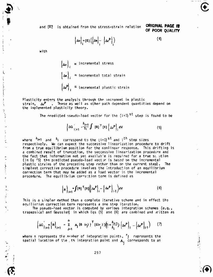
and [El i s obtained from the s t r ess - s t r a i n r e l a t i o n ORIGINAL PAGE 1s OF PO09 QUALllY
w i t h
1.0 I i E incremental s t ress
(Lli incremental t o t a l s t r a i n
i; (kp) incremental p l a s t i c s t r a i n i 1 I
P l a s t i c i t y enters t he ana lys is through t he increment i n p l a s t i c i. s t ra i n , & . These as we1 1 as o ther path dependent q u a n t i t i e s depend on
the impleqented p l a s t i c i t y theory. 2
* The n red ic ted .;seudo-load vector f o r the ( i+ l ) S t s tep i s found t o be
'i+l .- (AQ ,;+, -3; J [el [ E l ( ~ * P I ~ dV
. . where 'i+l and 6i correspond t the ( i + l ) S t and ith step s i r e s respect ively. We can expect the successive 1 inear i z a t ion procedure t o d r i f t
~. from a t r u e equ i l i b r i um p o s i t i o n f o r t he con l inear response. This d r i f t i n g i s a combined r e s u l t o f t runcat ion, t h e successive l i n e a r i z a t i o n procedure and .. the f a c t t h a t i n fo rmat ion not y e t ava i l ab ' e i s requi red f o r a t r u e sc i i t i o n - ( i n Eq '5) t h s p red ic ted pseudo-load v e c t w i s based on t he incremetital p l a s t i c s t r d i n s o f the preceding s tep ra the r them on the c u r r e i t step). The
s s implest c o r r e c t i v e procedure invo lves t h e i n t r oduc t ion o f an equi 1 i b r ium cor rec t ion term t h a t may be added as a load vector i r i t he incremental procedure. The equi l ib~. iurn co r re - , t i on term i s def ined a s
This i s a s impler method than a complete i t e r a t i v e scheme and i n e f f e c t t h o , equi 1 i r r i u m co r rec t i on term represents a one step i t e r a t i o n .
The pseudo-1 oad vector i s computed by v s r i ous i n t e g r a t i o n schemes (e.g. , trapezoiGa1 and Gaussian) i n which Eqs (5) and (G) are coabined and , w i t t e n as
7 where n represents t l e nl:;r,her o f i n t e g r a t i o n po;nts, j represents t h e
' L
s p a t i a l l o c a t i o n o f tt,e . t h i n t e g r a t i o n p o i n t and A corresponds t o an j
i n t e g r a t i o n weight f a c t o r f o r t h e j t h i n teg ra t i on point . The de r i va t i on o f t he pseudo-load vector f o r many o f t he NASTRAN elements i s presented i n re f . 2. The present study u t i l i z e s only t h e t r i a n g u l a r membrane element (CTRMEM) and t he extens I onal rod e l emcnt (CRCPI) .
IMPLEHENTATION OF ELASTIC-PLASTIC ANALYSIS INTO NASTRAN
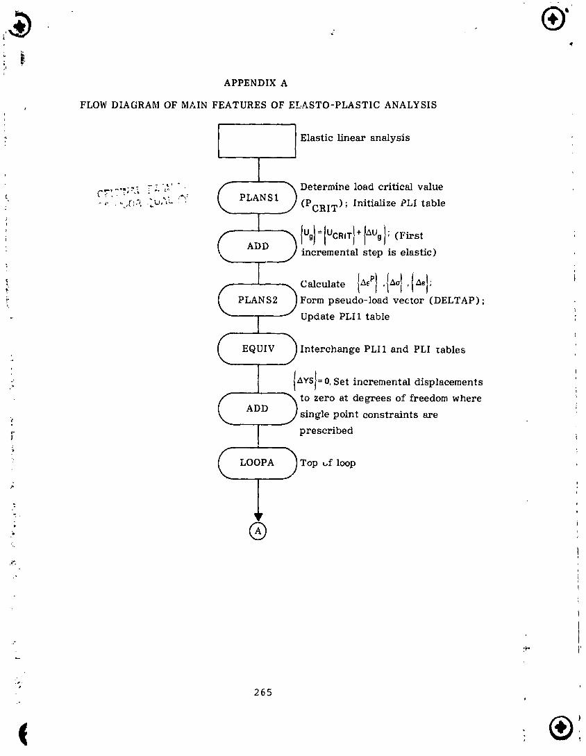
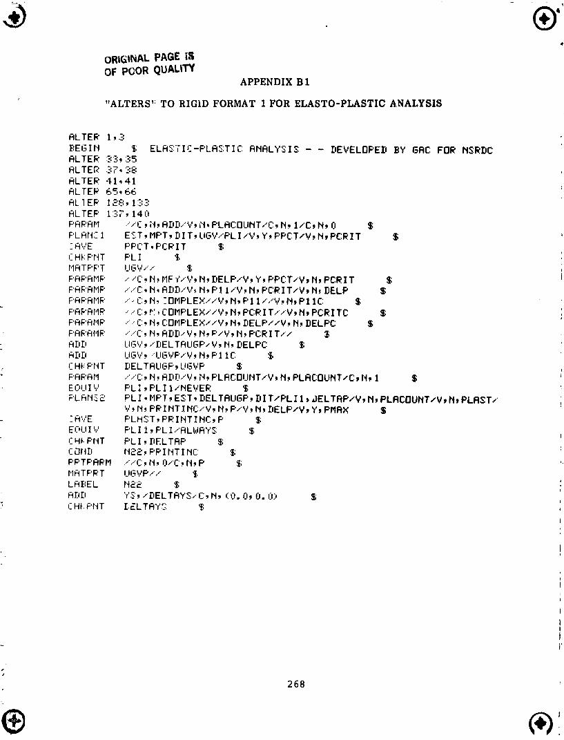
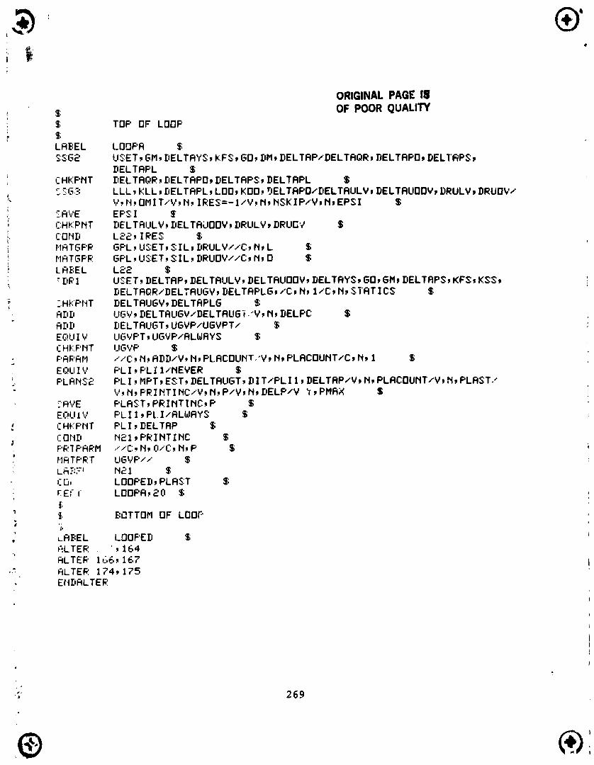
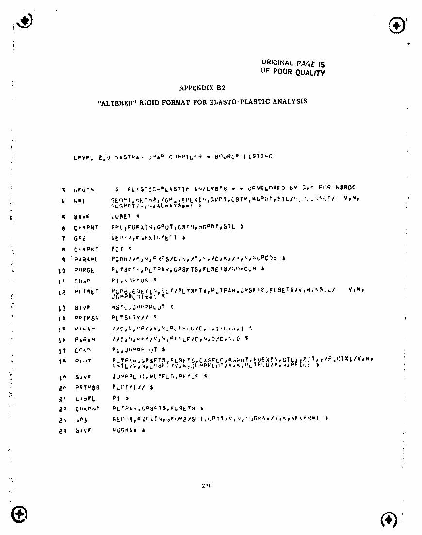
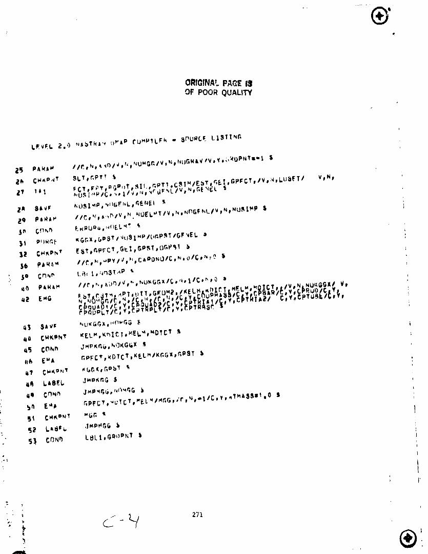
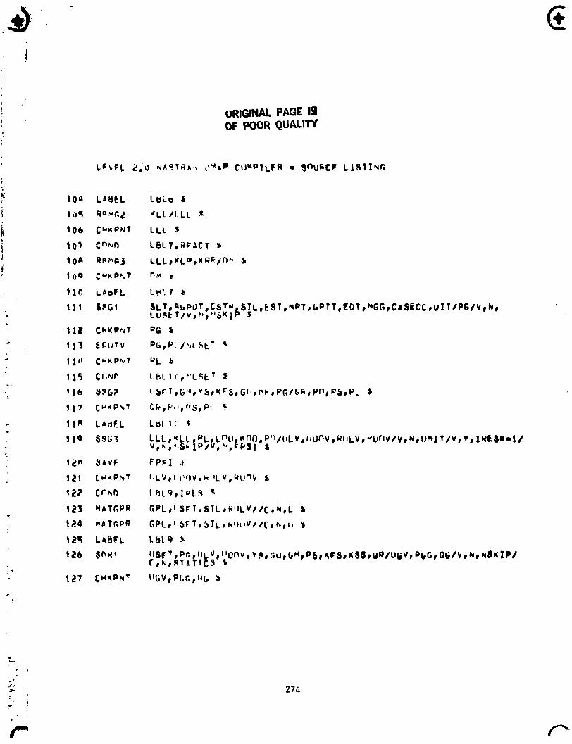
E l a s t i c - p l a s t i c c a p a b i l i t i e s have been incorporated i n t o t he NASTR?.N program. A f l w diagram, represent ing t h e i n t i t a l - s t r a i n method, i s shown i n Appen4ix A. The f unc t i on of each s tep i n the f low diagram i s explained. A correspondinq r i g i d format was w r i t t e n as a mod i f i ca t ion t o r i g i d format 1 (Level 17.0). m e ALTER package and r e s u l t i n g new r i g i d format are shown i n Appendices 01 and R2, respec t i ve ly .
Some o f t he important features of t h e new r i g i d format w i l l be mentioned. F i r s t l y , two new modules have been w r i t t en , PLANS1 and PLANS2. PLANS1 determines t he c r i t i c a l load, i.e., t h e lowest load amp1 i t ude f o r which a t l eas t one element s t ress po in t has become p las t i c . I n a d d i t i o n a new table, PLI, i s i n i t i a l i z e d . This t a b l e contains t he l a s t known f i e l d quan t i t i es s ~ c h as s t ress, s t r a i n and p l a s t i c s t r a i n . PLANS2 implements the e l a s t i c - p l a s t i c c o n s t i t u t i v e equations f o r incremental s t ress, s t r a i n and p l a s t i c s t r a i n . I n i t i a l l y on ly pe r f ec t p l a s t i c behavior o f the CTRMEM and CROO elements have been included. I n add i t i on PLANS2 updates the PLI t a b l e and forms the pspudo-load vector t he t he next p l a s t i c increment. The ca l cu la t i ons needed t o perform an e l a s t i c -p l as t i c ana lys is a re d iv ided i n t o thdse t h a t are performed one t i re and those t h a t are performed i n each incremental step, h o n g those t h a t a re performed once a re a l l t he usual funct ions necessary i n an e j a s t i c f i n i t e element analys is , i .e., reading input, a l l g lobal funct ions such as set: i ng up data tab les, and so l v i ng fqr
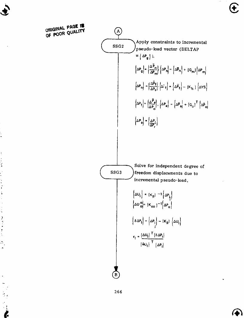
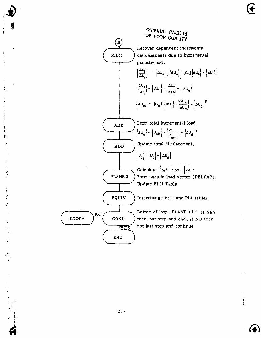
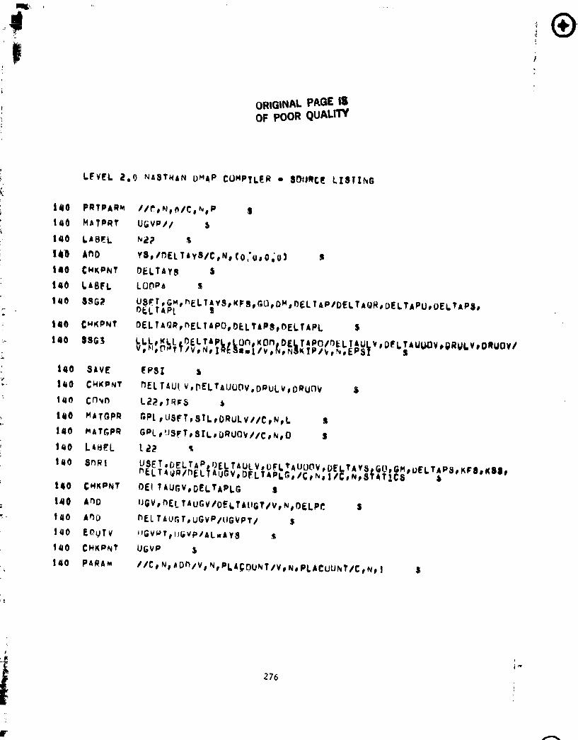
the e l a s t i c displacement f i e l d . These funct ions a re performed by t h e operat ional sequence cu r ren t l y i n r i g i d format 1 and are represented h:r the f i r s t b lock o f t he f low diagram. I n add i t ion , the c r i t i c a l load c a l c ~ l a t i o n and some p r e l iminary p l a s t i c ana lys is d e f i n i t i o n s are c a r r i e d crrt 3s shown i n the f law diagram above LOOPA, which i s the s t a r t of t he p l a s t i c i t y loop- The ca l cu la t i ons performed du r i ng each incremental step are contained i n the p l a s t i c i t y loop as shown i n the f low diagram. During edch pass through tDe p l ~ s t i c i t y loop t h e SSG3 module solves f o r t he incremental displacements due t o the p l a s t i c pseudo-load only. The incremental displacement due t o t h e ex te rna l load o r prescr ibed displacements a re known and a re added t o the incremental displacements due t o t he pseudo-load vector. The p l a s t i c i t y c o n s t i t u t i v e equat ions a re imp1 emented and t h e new pseudo-1 oad vector, t o be used ' - the next incremental step, i s formed (PLANS2). The p l a s t i c i t y loop i s repeated f o r each incremental step.
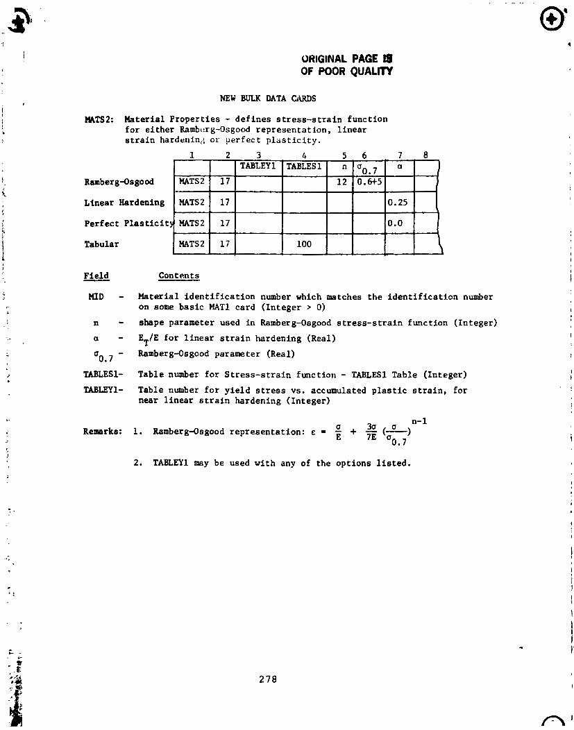
Three new bulk data cards have been added f o r l a t e r use i n a generzl e l a s t i c -p l as t i c a n a l y t i c capabi 1 i t y program. These are described i n Append: x C. The MATS2 bulk data card def ines t h e p l a s t i c mate r ia l p roper t ies ; the PLFAC2 bulk data card def ines tne load h i s t o r y and step s i ze in format ion; and t h e TABLEYl bulk data card def ines t he y i e l d s t ress as a funct :on of accumulattd p l a s t i c s t r a i n .

SAMPLE PROBLEM
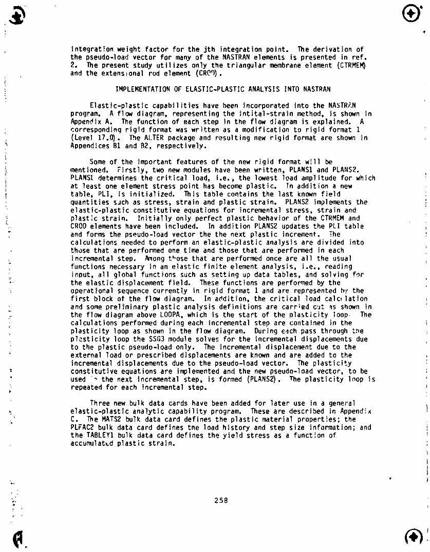
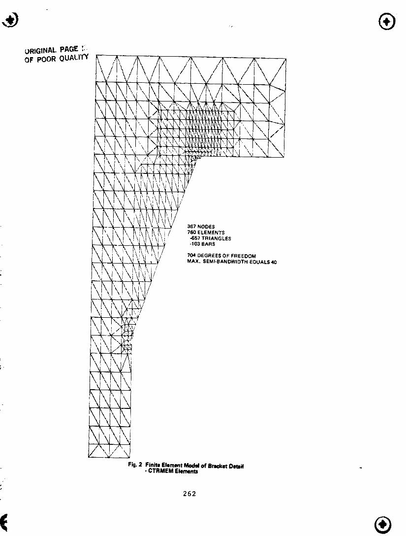
I n order t o va l i da te t he implemented NASTRAN c a p a b i l i t y an e l a s t i c - p l a s t i c ana lys is of a t y p i c a l s t r u c t u r a l d e t a i l o f a ship, namely a bracket connection, was performed us ing NASTRAN and t h e G r m a n PLANS program. Figure 1 shows the i n t e r s e c t i o n o f a ho r i zon ta l g i r d e r w i t h a t ransverse bulkhead. The shaded area represents the s t r u c t u r a l component t h a t was analyzed. Loads and boundary displacements on t h i s sec t ion were provided from a f i n i t e element model of the e n t i r e s t ructure. The f i n i t e element model consisted o f 657 membrane t r i a n q l e s f o r the webs, 103 rod elements f o r t he flanges (shown as do t ted l i r res i n Fig. 3) r e s u l t i n q i n 704 degrees o f freedom w i t h a semi-band w id th of 40. Figures 2 and 3 show t h e d e t a i l s o f t he f i n i t e element model. Figure 4 shows t he r e s u l t i n n j rowth of t he p l a s t i c reg ion o f the highest stressed sect i on.
The NASTRAN ana lys is was performed on a CDC cyber 172 computer and requi red 20 cpu seconds f o r each incremental step. The PLANS program,run on an I R M 37013033 computer, used 5 cpu seconds fo r each incremental step. The resu l t s from each program were i d e n t i c a l . Taking i n t o account the d i f ference between conputat ional speed of each computer (about 5:l) , t h e running t ime f o r the NASTRAN program i s compet i t ive w i t h t he PLANS proc 'am.
CONCLUSIONS
The present work demonstrates t h e feas i b i 1 i t y o f incorpora t ing e l a s t i c - p l a s t i c capahi l i t ies i n t o NASTRAN. The present imolementation included a general new r i g i d format and bulk data cards as we l l as two new modules. The modules a re spec ia l i zed t o inc lude only pe r f ec t p l a s t i c i t y o f the CTRMEM and CROD elements.
An extension of these c a p ~ b i l i t i e s t o inc lude general p l a s t i c behavior of the complete NASTRAN element 1 i b r a r y should present no new p i t f a l l s and w i l l be b r i e f l y out l ined. F i r s t l y , at? extens ion t o t h e f l ow char t and ALTER package would inc lude one new module, PLA5, used t o accumu!ate the t o t a l displacements (Table USVPAC) as w e l l as s t ress, s t r a i n and p l a s t i c s t r a i n (Table PLIAC) a t the end of each increment. It would apear as
PLA5 UGVP, PLI/UGVPAC ,PLIAC/V,N ,PLACOUNT/V,N ,P
I n addi t ion, new tab les would b t s e t up i n PLANS1 and would conta in element i n t e g r a t i o n p o i n t i n f o r m a t i ~ n . To form these tab les, use,. spec i f i ed informat ion wouid be suppl i e d on bu lk data cards through fiew element proper ty cards.
Module PLANS2 must be genera; i zed t o b u i l d a pseudo-load vector, Eq (7) , from the new tab les se t up i n PLANSl. I n add i t ion , t he p l a s t i c i t y theory contained i n PLANS% should be expanded t o include, i n a d d i t i o n t o per fec t p l a s t i c i t y , 1 inear strain-hardening, nonl inear s t ra in-hardening using e i t h e r a Ramberg-Osgood func t ion o r a s t r ess -s t ra i n tab le , o r any other theory cons is tant k i t h t he i n i t i a l s t r a i n approach t h a t the developer wants t o i ncorporate.

REFERENCES
1. Levy, A * , and Pifko, A.B., " F e a s i b i l i t y Study fo r the Incorporat ion of Nonl inear Capabi 1 i t y i n t o NASTRAN," Grumman Research Department Report, RE-593, Grumman Aerospace Corporation, January 1980.
2. Crouzet-Pascal, J., and Levy, A., "Pseudo-Load Formulation f o r NASTRAN mater ial Nonl inear Analysis using I n i t i a l -Strain Method," Grumman Research Department Report, RE-594, Grumman Aerospace Corporation, March 1980.
3. Levy, A * , and Pifko, A.R., "On Computational St rategies fo r Problems invol ving F las t i c i t y and Creep," In te rna t iona l Journal f o r Numerical Methods i n Engineering, Vol. 17, pp. 747-771 (1981).
4. Pifko, A.R., Levine, H.S., Armen, Jr. , H., and Levy, A,, "PLANS - A f i n i t e element program f o r nonl inear analys is o f structures," ASME Prepri n t 74-WA/PVP-6(1974) .
ORIGINAL PAGE B OF POOR QUALITY
AREA OF FINITE ELEMENT
Fig. 1 Sttrn~etural Detail of Bracket Ccamtier!
ORIGINAL PAGE I:, OF POOR Q U A C ~
Fig. 2 Finite Element Modal of Brrdtot Domil - CTRMEM Elemtm

Fig. 3 Finite Element M d e l of Bracket Detail - CROD Elemn* for Flanges
0RIGlrJl"rL F&f 13 OF POOR QUALlN

P = .3155
INITIAL YIELD
P = .4417
INITIAL PLASTICITY IN FLANGE
Fig. 4 Growth of the Elastio-Plastic Boundary in Region of L a r ~ t Stress
APPENDIX A
FLOW DIAGRAM OF MAIN FEATURES OF ELASTO-PLASTIC ANALYSIS
l - 7 Elastic linear analysis
- : - < I - , -my; 7,; i #.. ;. (y'... . Determine load critical value ., % : .,-:,: - C: , l.L:(!-*i, ,&e, b b . . PLANS1
('GRIT ; Initialize PLI table
(ugJ=(ucRITJ+ pug 1; ( ~ i r s t
incremental step is elastic)
Calculate ( A ~ P ) . ( ~ 0 1 . (be1 ;
Form pseudo-load vector (DELTAP) ;
Update PLI1 table
(G) Interchange PLI 1 and PLI tables
I ( ~ y s l - 0. Set incremental displacements
\ to zero at degrees of freedom where -
single point constraints are
prescribed
LOOPA Top clf loop
Apply constraints to incremental
pseudo-load vector (DELTAP
= 1 APg 1 1,
Solve for independent degree of
SSG3 freedom displacements due to
incremental pseudo-load,
(7) Recover dependent int!remental
displacements due to incremental
pseudo-load ,
AYS
d F - 7 Form total incremental load,
( ADD I Update total displacement,
,,,,ate ( A ~ P , 1 I , I*.) :
Form pseudo-load vector (DELTAP) ;
Update PLJ1 Table
EQUIV Interchange PLIl and PLI tables a Bottom of loop; PLAST <1 ? If YES
LOOPA then last step and end, if NO then
not last step and continue
ORIC;!NAL PAGE is OF POOR QUALITY
APPENDIX B1
"ALTERS': TO R IG iD FORMAT 1 FOR ELASTO-PLASTIC A.NALYSIS
HLTEP l r 3 BEG I N 9; ELAS'i 11: -PLfiI:T I S - - f: ANAL'tSI DEVELOPED BY GAC FOR NSRDC HLTER 339 35 ALTER .I-:?- 3E: ALTER 4 1 - 4 1 ALTEP 6,s- &t5 AL 1 EP 1287 1 :I:.> ALTEF' 137r 141:l F'AF'HI.1 ...'..,.'C 9 ;Jr ADD,..'Vr M. PLfiCOIJNTfCr Nr l / 'Cr Nr IJ $ F'LAIi:: 1 E"I.Tr MPTr D I Tr lIC,V*iPLI/'Vr Y r PPC:T/Vr Nr PC:RIT $ - rr f f , !~ PPC'T. F'C:RIT 9;
CHI.:F'PiT F'LI '1, P~ATPI;'T r_l~;~~i,..',,. 9; F'AF'APIF' .... <.'C'r Nr MF ~ ' l ' V r Nr DELPlWr Pr PPCT/'Vr Nr PCRIT S F'AF;.AI.lF ..>'....' Cr N. HDD/'Vr Nr P I 1 /'Vr Nr PCRIT/Vr Nr DELP $ PAF'F(MF' ....'.. C : r I J ~ ~ O M P L E X . " / ' V ~ N r F ' 1 1 / . , ' V r N ~ P l l C $
F'APtiPlR ,.. .>, C: r !.: 9 C'OMPLEX//Vr N PC:R I T//V r N 9 PCRI TC 9; F'HF'AMF' ...'...C:r Nr C:OflPLEX/'/Vr Nr DELP//Vr Nr DELPC S I ...'..*'C'r Nr fiDD/$'. N? F'/Vr N 9 PC:R 1 T// 3 ADD 1-16'4 r ,*'DELTfiUGP/Vr Nr DELPC 9; A 11 11 I-IISV r ~'l-lC,VF'/'V r N 2 P 1 1 C: % CHI: F'PiT DELTHUGFr UGVP % F'ARAM ,,'..*'C: r Nr HDD/'Vr Nr PLAC:OUNT/Vr Nr PLHCOUNT/Cr Nr 1 $ E 13 11 I i,! F'L:rPLIl/NEVER R F'LtiN.12 PL I - MF'T 7 EST- DELTAUGP r D I T/PL I 1 5 L)ELTHP/Vv Nr PLACOUNT/Vv N, PLAST/.
Or NT PF'1NTINC:~'Vr Nr P 4 " Nr DELP/Vr Y r PMAX - A!,!E
$ F'LHSTr PRINTXNCr P 9;
E [I 11 I !; F'L I 1 9 PL I .'HLWfi','S 9; CHI. F'NT F'LI 9 TIELTAP 9; C dtiD N22r PFINTINC: 9; F'F'TPHPN .,',.'CC r N r O/'C'. N:, P 1; PlATF'FT UB$(P/',,' 9. LAE:EL N22
6, '7. 9;
AD11 t . 2 I /.DELTAPS/C'rNr r:O. 0 9 0. 0) CHI. PPiT I.ELTA't::: 9;
1.Hk';F'IJT HIID HDD EQCI I V C HI;F'NT PFlk AM EI;!CI I V PLAI.1I:i'
"nI)E EC!U i V CYK'PNT C 0P1D PR1PARM MATPRT L fi F; ;-- I
1: Ll FEf I' f;
ORIGINAL PAGE I8 OF POOR QUALITY
TOP OF LOOP
LOflPA 9; USETr SMr DELTAYSr KFSr 609 DMr DELTAP/DELTAQRr IlELTRPOr DELTRPSr DEL THPL 5. DELTABRrDELTAPOrDELTAPSrDELTRPL $ LLLrKLLrDELTAPLrLOOrI(OO~rJELTRPO~DELTAULYrDELT~UOOVr~RULVrDRU0V~ Vr Nr ONIT/VrNr I R E S = - ~ / ~ ~ ~ N ~ N S K I P / V ~ N Y E P S I $ EPS I F DELTkULVr DELTHUOOVr DRLILVr DRLIC14 $ L22 r IRES 9; CPLr USETr S I L r DHULV/iCrNrL S GPL 9 USETr S I L r DRUOV//Cr Nr 0 $ L 2 2 $ USETr DELTAPr DELTAULVr DELTAUOOVr DELTAYSr GO? GMP DELTRPSr UFSs KSSr D E L T A Q R / D E L T A U G V ~ D E L T A P L ~ ~ ~ C ~ N ~ ~ ~ C C N ~ S P A T I C S $ DELTAUGV r DELTHPLG $ CIGVr DELTAUCV/DELTAUGS ."Vr Nr DELPC $ DELTAUGTrUGVP/UGVPT/ S UGVPTr UGVP/ALWAYS 5. UCVP $ //C r Nr HDD/V.Q Nr PLRCOUNT,'Vr Nr F'LACOUNT/Cr NY 1 S PLI rPLI l /NEVER S P L I ~ M P T ~ E S T ~ D E L T R U G T ~ D I T / P L I ~ ~ D E L T R P / V ~ N P P L R C O U N T / V ~ N ~ P L H S T . ~ PrNrPRINTINC/'VrNrP/VINIDELP/V LrPMK4 $ PLHSTr PRINTINCr P $ FLX 1 r PL,I/ALWAYS $ FL I I DELTAP $ N21rPHINTINC $ ,.'/Cr Nr O/'C:r Nr P S UC;$'P/, s Nc'l 9; LOOPED 9 PLAST $ LOOPAr20 S
BCTTOM OF LOOP P
LHBEL LOOPED S GLTER . ' r 164 HLTEF lG6r 167 HLTER 1749 175 EPIIlkLTER
ORlGiNAi PAGE 6 OF POOR QUALlW
APPENDIX B 2
"ALTERFD" RiGID FORMAT FOR ELASTO-PLASTIC ANALYSIS
ORfGfNANAC PABE W 9F POOR QUALIM

73 c m n C B L ~ , GLWL J
74 GPSP GPL ,GPqT,uSET, ! I IL/nGPST/V, Y,NlIGPST S
75 8 4 V f N L ) I ; P S T J
76 CnNn 1 bLu, hflijP;iT 5
77 UFP ( J G P S t , , , , , / / S
76 LAnFL Ldl-4

ORIGINAL PAGE 19 Of POOR QUALlW
K G G , I ~ Q ~ J / W P C F ! S
w q h' $
Ld?,?, .'w,=L f
U S € T # hG/Sk S
G* S;
USFT , G ~ # d G C # , , /dN%, # , 5
Uh.4 s
L B l Z 5
K ~ J h , ~ F r / $ I ~ G L ~ Y
YFF *

ORIGINAL PAGE IS OF POOR QUALITY
L)F P
P A R A M
PLAN81
S b V F
CWkPNT
n 4 t P R T
P A R I M P
P A R A M R
PAk'AMu
PA R A M R
C b R b M R
P ~ R A M R
A nD
ADD
CHKPNT
PAHAM
m u r v -
CL A N3E
ORIGINAL PAGE I8 OF POOR Q U A L ~
iro CWKPNT
I40 An0
146 AOL)
1 4 0 eoyrv 140 C H K P N ~
0 P A R A M

ORIGINAL PAGZ 13 OF POOR Q l i A L l n
L4BFL
END
ORIGINAL PAGE 18 OF POOR QUALITY
NEW BULK DATA CARDS
MATSZ: Material Proper t ies - d e f i n e s s t r e s s - s t r a i n funct ion f o r e i t h e r Rambcrg-Osgood representa t ion, l i n e a r s t r a i n hardanin,; o r pe r fec t p l a s t i c i t y .
Ramberg-Osgood
Linear Hardening
Perfect P l a s t i c i t
Tabular I I I I I I I
Field - Contents
MID - Mater ia l i d e n t i f i c a t i o n number which matches the i d e n t i f i c a t i o n number on some bas ic MAT1 card ( In teger > 0)
n - shape parameter used i n Ramberg-Osgood s t r e s s - s t r a i n function ( In teger)
a - ET/E f o r l i n e a r s t r a i n hardening (Real)
a - Ramberg-Osgood parameter (Real) 0.7
TABLES1- Table number f o r S t r e s s - s t r a i n functiort - TABLES1 Table ( In teger)
TABLEY1- Table number f o r y i e l d s t r e s s vs. accumulated p l a s t i c s t r a i n , f o r near l i n e a r s t r a i n hardening ( Integer)
0 30 0 n-1
Remarks: 1. Ramberg-Osgood representa t ion: E = - + - (-) E 7E a0.7
2. TABLEYl may be used with any of the opt ions l i s t e d .
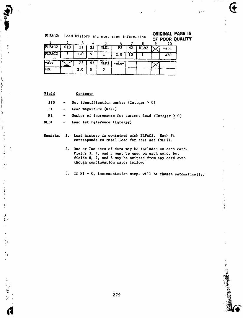
PLFACZ: Load h i s t o r y and s t e p s i z e inform,t ic ,n ORIGINAL PAGE 15 OF POOR QUALIW
Fie ld - Contents
- 5 6 7 8 9 10 ~m "1 PUC N L D ~ 1~ +abc
SID - S e t i d e n t i f i c a t i o n number ( In t ege r > 0)
P i - Load magnitude (Real)
N i - Number of increments f o r cu r ren t loed ( In t ege r > 0) - NLDi - Load set r e fe rence ( In t ege r )
Remarks: 1. Load h i s t o r y is contained wi th PLFAC2. Each P i corresponds t o t o t a l ioad f o r t ha t set (NLDi) .
LFAC 2 1 .O
2. One o r Two sets of d a t a may be included on each card . F i e l d s 3, 4, and 5 must be used on each card , but f i e l d s 6, 7, and 8 may be omit ted from any card even though con t inua t ion cards follow.
1
NLD3
2
+abc
+BC i
3. If N i = 0, incrementat ion s t e p s w i l l be chosen automa t i c a l l y .
2.0
1 / .,A
-etc-
10
P3
3.0
1 ABC
N3
5
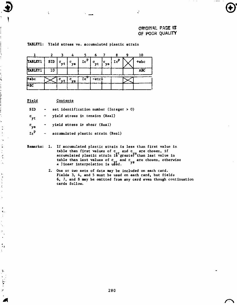
TABLEY1: Yield s t r e s s vs. accumulated p l a s t i c s t r a i n
1 I I I I I I V u LEY11 101 I I I 1 I I ABc
1 2 3 4 5 . 6 7 8 9 10
Fie ld - Contents
SID - s e t i d e n t i f i c a t i o n number ( In teger > 0)
a - yie ld s t r e s s i n tension (Real) Y t
LEY1 SID a a rep a a Y t YE Y t YS
u - yie ld s t r e s s i n shear (Real) YS
C E ~ +abc
CcP - acc-lated p l a s t i c s t r a i n (Real)
Remarks: 1. I f accumulated p l a s t i c s t r a i n i s l e s s than f i r s t value i n t a b l e then f i r s t values of a and a a r e chosen, i f accumulated p l a s t i c s t r a i n 18 greateTSthan l a s t value i n t a b l e than l a s t values of a + and a a r e chosen, otherwise a I inear in te rpo la t ion is uged.
2. One o r two s e t s of data may be included on each card. Fie lds 3, 4, and 5 must be used on each card, but f i e l d s 6, 7 , and 8 may be omitted from any card even though cenrinuation cards follow.
Top Related