


Languages
Pages
Legal

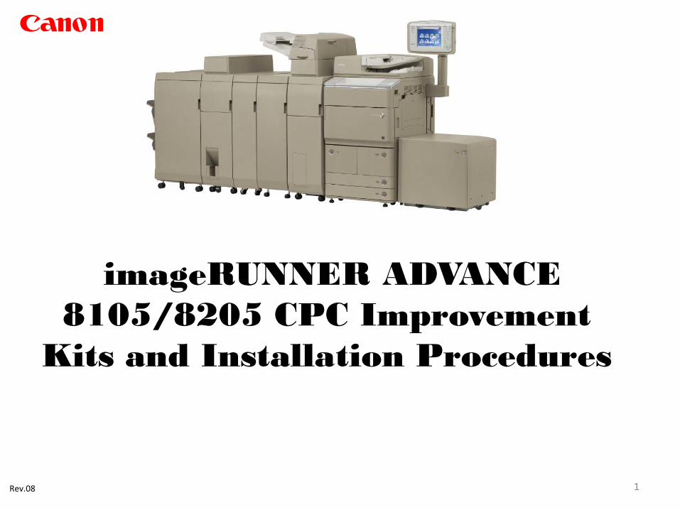
imageRUNNER ADVANCE 8105/8205 CPC Improvement
Kits and Installation Procedures
1 Rev.08
Canon
Important Note
2
IMPORTANT NOTE: Canon U.S.A. Inc. recommends the replacement of consumable and routine maintenance parts at the intervals recommended in the imageRUNNER ADVANCE 8105/8205 Series Service Manual. However, during the course of the installation of these kits, it is possible that additional severely worn and/or damaged parts may be encountered as the procedures in this manual are performed. To experience the maximum benefit of these CPC Improvement kits, the service technician may want to consider replacement of such parts (if applicable) at the time of this installation. For Kit “A”, we recommend performing the procedures in the order presented in this document. This will allow the Fixing Assembly to cool down before installing the countermeasure parts for “Off-Set”.
Kit Information
3
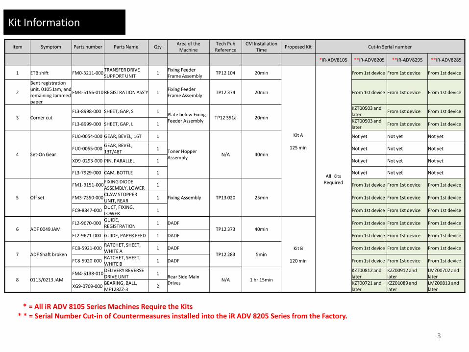
Item Symptom Parts number Parts Name Qty Area of the
Machine Tech Pub Reference
CM Installation Time
Proposed Kit Cut-in Serial number
*iR-ADV8105 **iR-ADV8205 **iR-ADV8295 **iR-ADV8285
1 ETB shift FM0-3211-000 TRANSFER DRIVE SUPPORT UNIT
1 Fixing Feeder Frame Assembly
TP12 104 20min
Kit A
125 min
All Kits Required
From 1st device From 1st device From 1st device
2
Bent registration unit, 0105 Jam, and remaining Jammed paper
FM4-5156-010 REGISTRATION ASS'Y 1 Fixing Feeder Frame Assembly
TP12 374 20min From 1st device From 1st device From 1st device
3 Corner cut FL3-8998-000 SHEET, GAP, S 1
Plate below Fixing Feeder Assembly
TP12 351a 20min
KZT00503 and later
From 1st device From 1st device
FL3-8999-000 SHEET, GAP, L 1 KZT00503 and later
From 1st device From 1st device
4 Set-On Gear
FU0-0054-000 GEAR, BEVEL, 16T 1
Toner Hopper Assembly
N/A 40min
Not yet Not yet Not yet
FU0-0055-000 GEAR, BEVEL, 13T/48T
1 Not yet Not yet Not yet
XD9-0293-000 PIN, PARALLEL 1 Not yet Not yet Not yet
FL3-7929-000 CAM, BOTTLE 1 Not yet Not yet Not yet
5 Off set
FM1-B151-000 FIXING DIODE ASSEMBLY, LOWER
1
Fixing Assembly TP13 020 25min
From 1st device From 1st device From 1st device
FM3-7350-000 CLAW STOPPER UNIT, REAR
1 From 1st device From 1st device From 1st device
FC9-8847-000 DUCT, FIXING, LOWER
1 From 1st device From 1st device From 1st device
6 ADF 0049 JAM FL2-9670-000
GUIDE, REGISTRATION
1 DADF TP12 373 40min
Kit B
120 min
From 1st device From 1st device From 1st device
FL2-9671-000 GUIDE, PAPER FEED 1 DADF From 1st device From 1st device From 1st device
7 ADF Shaft broken FC8-5921-000
RATCHET, SHEET, WHITE A
1 DADF TP12 283 5min
From 1st device From 1st device From 1st device
FC8-5920-000 RATCHET, SHEET, WHITE B
1 DADF From 1st device From 1st device From 1st device
8 0113/0213 JAM FM4-5138-010
DELIVERY REVERSE DRIVE UNIT
1 Rear Side Main Drives
N/A 1 hr 15min
KZT00812 and later
KZZ00912 and later
LMZ00702 and later
XG9-0709-000 BEARING, BALL, MF128ZZ-3
2 KZT00721 and later
KZZ01089 and later
LMZ00813 and later
* = All iR ADV 8105 Series Machines Require the Kits * * = Serial Number Cut-in of Countermeasures installed into the iR ADV 8205 Series from the Factory.

ETB Shift
Symptom:
The Electrostatic Transfer Belt (ETB) can at times displace toward the front or the rear side during normal operation. This symptom can cause the ETB to rub against the Transfer Frame, possibly causing the ETB to wear out pre-maturely.
Cause:
The ETB [3] was designed to stay in the center position of the ETB Ass’y [2]. However, if the position between the Fixing / Feeder Duplexing Ass’y [1] and the E.T.B Ass’y [2] is slightly off, the force which pulls the ETB [3] toward the rear or the front side is increased. If this occurs the ETB may [3] displace to the extreme front or the extreme rear side.
Factory:
The Transfer Drive Support Ass’y [B] (Figure 2) has been added along with the Transfer Drive Shaft Alignment Adjustment Mechanism to make it possible to service when displacement of the ETB [3] is out of specification.
4
Kit A
Parts Information: TRANSFER DRIVE SUPPORT UNIT FM0-3211-000

ETB Shift
Service work:
Perform the following steps when displacement of the ETB [3] is out of specification:
1. Open the Front Cover.
2. Slide out the Fixing / Feeder Duplexing Ass’y [1].
3. Check to see if ETB [3] has displaced toward the rear or the front side.
3-A. How to check the ETB displacement toward the rear side:
If the length [La] (Figure 3) between the engraved mark (straight line) of the Front Transfer Roller Holder [4] on the front side and ETB [3] is 8mm or more; continue to step 4.
3-B. How to check the ETB displacement toward the front side:
If the length [Lb] (Figure 4) between the engraved marks (straight line) of the Rear Transfer Roller Holder [5] on the rear side and ETB [3] is 8mm or more; continue to step 4.
5
Kit A
ETB Shift
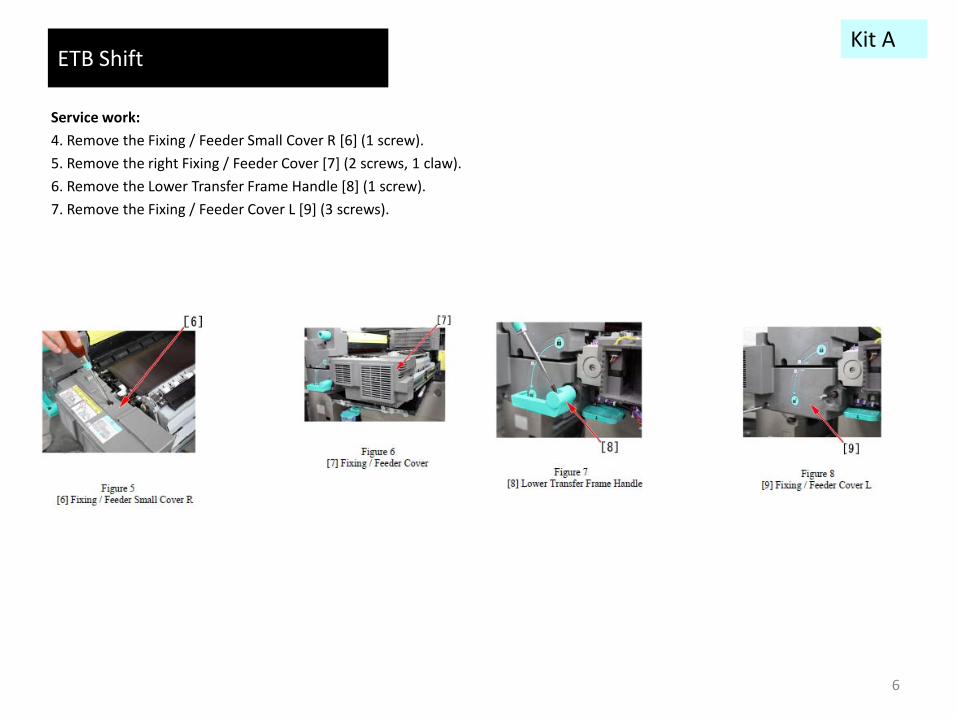
Service work:
4. Remove the Fixing / Feeder Small Cover R [6] (1 screw).
5. Remove the right Fixing / Feeder Cover [7] (2 screws, 1 claw).
6. Remove the Lower Transfer Frame Handle [8] (1 screw).
7. Remove the Fixing / Feeder Cover L [9] (3 screws).
6
Kit A

ETB Shift
Service work:
8. Remove the Transfer Duct Fan Unit [10] (2 screws, 1 connector).
9. Remove the ETB Ass'y.
10.Remove the Transfer Drive Unit [11] (3 screws, 1 connector).
11. From the Transfer Drive Unit [11], remove the DC Stepping Motor [12] (2 screws), the E-ring [13], the 26T Gear / 30T Pulley [14], the Cogged Timing Belt [15] and the Wire Saddle [16] (x 2pcs).
7
Kit A
ETB Shift
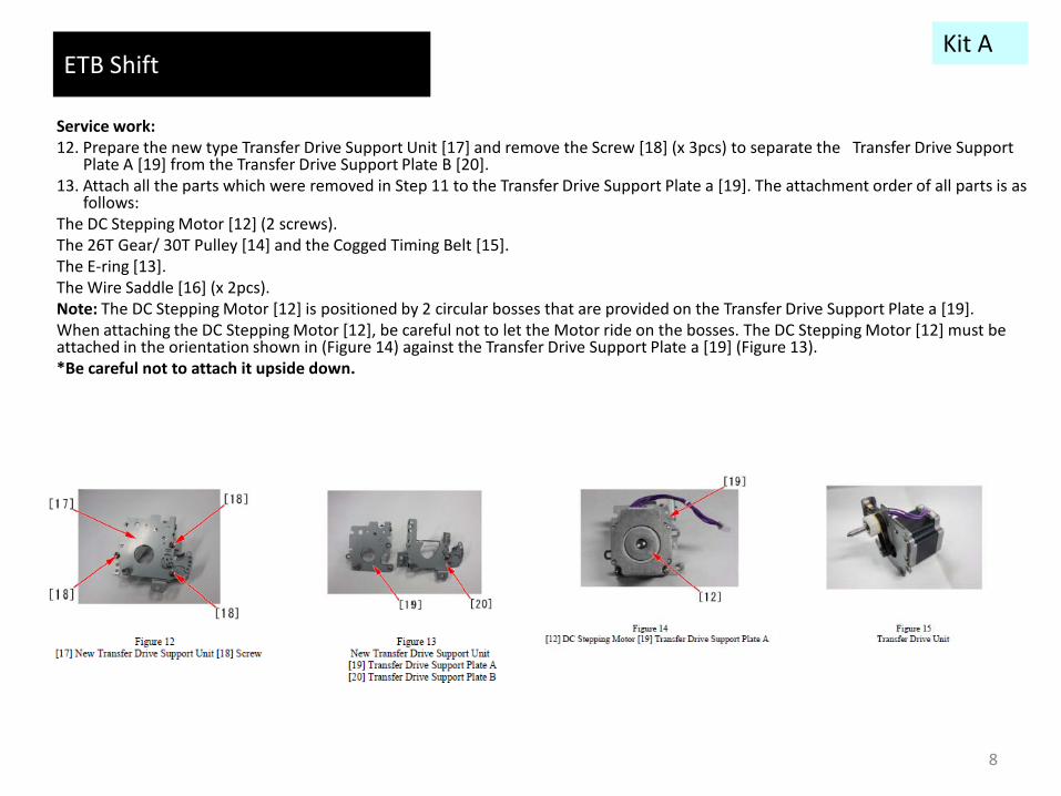
Service work: 12. Prepare the new type Transfer Drive Support Unit [17] and remove the Screw [18] (x 3pcs) to separate the Transfer Drive Support
Plate A [19] from the Transfer Drive Support Plate B [20]. 13. Attach all the parts which were removed in Step 11 to the Transfer Drive Support Plate a [19]. The attachment order of all parts is as
follows: The DC Stepping Motor [12] (2 screws). The 26T Gear/ 30T Pulley [14] and the Cogged Timing Belt [15]. The E-ring [13]. The Wire Saddle [16] (x 2pcs). Note: The DC Stepping Motor [12] is positioned by 2 circular bosses that are provided on the Transfer Drive Support Plate a [19]. When attaching the DC Stepping Motor [12], be careful not to let the Motor ride on the bosses. The DC Stepping Motor [12] must be attached in the orientation shown in (Figure 14) against the Transfer Drive Support Plate a [19] (Figure 13). *Be careful not to attach it upside down.
8
Kit A

ETB Shift
Service work: 14. Depending on the displacement direction of ETB, adjust the Transfer Drive Support Plate B [20] as follows: Loosen the screw [21]. If ETB has displaced toward the rear side, raise the position of the Cam Plate [22] (Figure 16) by 1 hole from the initial position as
shown in [D] (Figure 16); tighten the Screw [21]. If ETB has displaced toward the front side, lower the position of the Cam Plate [22] (Figure 16) by 1 hole from the initial position, as
shown in [E] (Figure 16); tighten the screw [21]. Note: Do not use the top and bottom holes on the Cam Plate [22]. When tightening the screw [21], be careful not to let the Cam Plate [22]
ride on the bosses of the Transfer Drive Support Plate B [20]. 15. Attach the Transfer Drive Support Plate B [20] to the Transfer Drive Support Plate A [19]. The Transfer Drive Support Plate A [19] is positioned by the 2 circular bosses which are provided on the Transfer Drive Support Plate B [20]. Note: When attaching the Transfer Drive Support Plate, be careful not to let the Support Plate B [20] ride on the bosses. Also, pay attention
not to damage the Cogged Timing Belt [15]. 16. Install all the removed parts (Steps 4 ~ 9) in the reverse order. How to check the improvement of the ETB displacement
1. In the Duplex mode, feed a total of 200 LTR-size paper. 2. Upon completion, check to see if displacement of the ETB is within specification.
9
Kit A
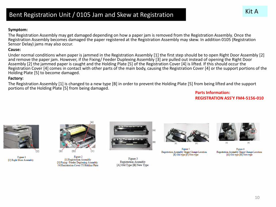
Bent Registration Unit / 0105 Jam and Skew at Registration Symptom: The Registration Assembly may get damaged depending on how a paper jam is removed from the Registration Assembly. Once the Registration Assembly becomes damaged the paper registered at the Registration Assembly may skew. In addition 0105 (Registration Sensor Delay) jams may also occur. Cause: Under normal conditions when paper is jammed in the Registration Assembly [1] the first step should be to open Right Door Assembly [2] and remove the paper jam. However, if the Fixing/ Feeder Duplexing Assembly [3] are pulled out instead of opening the Right Door Assembly [2] the jammed paper is caught and the Holding Plate [5] of the Registration Cover [4] is lifted. If this should occur the Registration Cover [4] comes in contact with other parts of the main body, causing the Registration Cover [4] or the support portions of the Holding Plate [5] to become damaged. Factory: The Registration Assembly [1] is changed to a new type [B] in order to prevent the Holding Plate [5] from being lifted and the support portions of the Holding Plate [5] from being damaged.
10
Kit A
Parts Information: REGISTRATION ASS'Y FM4-5156-010

Bent Registration Unit / 0105 Jam and Skew at Registration Service work: If the above symptom occurs, replace the Registration Assembly [1] with the new type [B]. The procedure of replacing the Registration Assembly [1] is as follows. (Refer to the service manual as well.) 1. Pull out the Fixing/ Feeder Duplexing Assembly [3]. 2. Remove the Fixing/ Feeder Right Front Upper Cover [6]. (1 screw) 3. Lift the ETB Assembly [7] in the direction of the arrow. 4. Disconnect the 2 connectors [8]. 5. Set the ETB assembly [7] back and remove the Registration Assembly [1]. (4 screws). 6. Install the new type Registration Assembly [B]. (4 screws) 7. Assemble the disassembled parts in reverse order to complete the work. Note: When installing the Registration Assembly [1] in the main body, perform the work with the attention to the following 2 points. When installing the Registration Assembly [1], be sure to check that the 2 positioning pins [9] are secured to the holes of the Fixing/ Feeder
Duplexing Assembly [3]. Be sure to follow the order as shown in the below figure P-12 to tighten the 4 screws.
11
Kit A

Corner Cut Kit A
12
Symptom: When LDGR or larger sized paper is used during duplex printing, the corner of the sheet may get cut off. The cut will be a triangular fragment (Figure 1) of paper left inside the main body. Cause: As the edge of paper goes into the gap [a] in-between the Left Deck Pick-up Unit [1] and the Left Deck Partition Plate [2] (Figure 2), the corner portion of the sheet may get cut off. Factory: To close up the gap [a] between the Left Deck Pick-up Unit [1] and the Left Deck Partition Plate [2], attach the newly added S Gap Sheet [3] and the L Gap Sheet [4] onto the Left Deck Partition Plate [2].
Parts Information: SHEET, GAP, S FL3-8998-000 SHEET, GAP, L FL3-8999-000
13
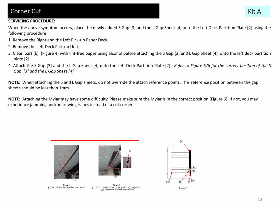
SERVICING PROCEDURE:
When the above symptom occurs, place the newly added S Gap [3] and the L Gap Sheet [4] onto the Left Deck Partition Plate [2] using the following procedure:
1. Remove the Right and the Left Pick-up Paper Deck.
2. Remove the Left Deck Pick-up Unit.
3. Clean part [b] (Figure 4) with lint-free paper using alcohol before attaching the S Gap [3] and L Gap Sheet [4] onto the left deck partition plate [2].
4. Attach the S Gap [3] and the L Gap Sheet [4] onto the Left Deck Partition Plate [2]. Refer to Figure 5/6 for the correct position of the S Gap [3] and the L Gap Sheet [4].
NOTE: When attaching the S and L Gap sheets, do not override the attach reference points. The reference position between the gap sheets should be less then 1mm. NOTE: Attaching the Mylar may have some difficulty. Please make sure the Mylar is in the correct position (Figure 6). If not, you may experience jamming and/or skewing issues instead of a cut corner.
Corner Cut Kit A

1) Open the Front Cover. 2) Open the Inner Cover (Primary Charging Air Supply Fan Unit). • 1 Screws (to loosen) 3) Remove the Inner Cover (Primary Charging Air Supply Fan Unit). • 1 Connector • 2 Protrusions
Note: When starting the host machine, be sure to set the Shutter from CLOSE to OPEN.
4) Move the lever in the direction of the arrow to close the Shutter.
5) Remove the Front Upper Cover. • 2 Hinge Pins • 2 Springs
6) Release the Lock Lever to remove the Toner Bottle.
7) Remove the Toner Receptacle Tray. • 1 Screw • 1 Protrusion
Note: 1. Toner can be accumulated in the Toner Receptacle Tray; therefore, be careful not to spill toner when removing. 2. Be sure to fit the protrusion into the groove of the plate to install.
8) Remove the Connecting Drive Unit. • 1 Screw
9) Pull out the Fixing Feed Unit.
Note: When pulling out the Fixing Feed Unit, be sure to place paper over the ETB Unit for protection.
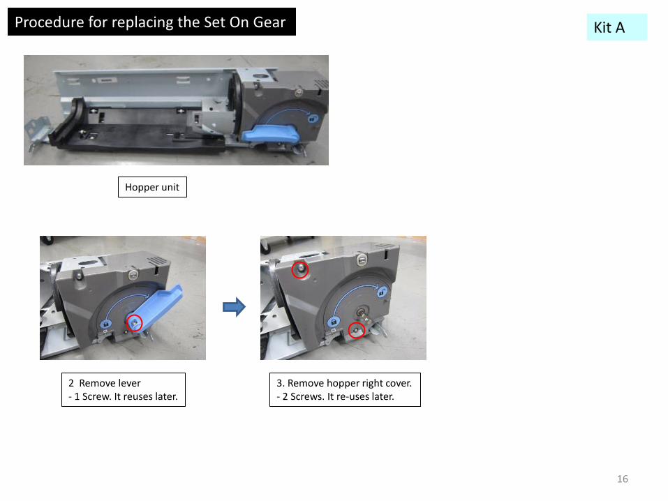
1. Remove hopper unit
Procedure for replacing the Set On Gear Kit A
14

10) Remove the Left Upper Cover 2. • 1 Screw • 1 Protrusion
11) Set the Fixing Feed Unit back. 12) Remove the Right Upper Inner Cover. • 4 Screws • 1 Connector • Harness
13) Set the Lock Lever back.
14) Remove the Hopper Unit. • 4 Screws • 2 Connectors • 1 Hook
Procedure for replacing the Set On Gear Kit A
15
Parts Information: GEAR, BEVEL, 16T FU0-0054-000 GEAR, BEVEL, 13T/48T FU0-0055-000 PIN, PARALLEL XD9-0293-000 CAM, BOTTLE FL3-7929-000
Procedure for replacing the Set On Gear
Hopper unit
2 Remove lever - 1 Screw. It reuses later.
3. Remove hopper right cover. - 2 Screws. It re-uses later.
Kit A
16

4. Remove hopper drive unit - 6 Screws. It reuses later - 2 Connectors
5. Remove lever idler gear - 3 screws. It reuses later
Procedure for replacing the Set On Gear Kit A
17
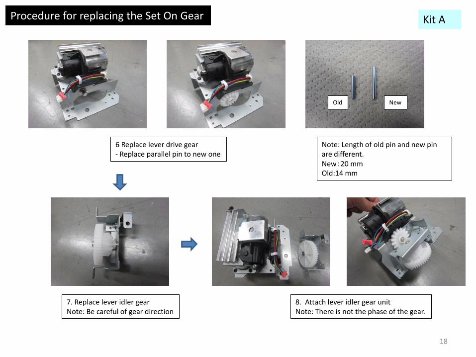
6 Replace lever drive gear - Replace parallel pin to new one
7. Replace lever idler gear Note: Be careful of gear direction
Note: Length of old pin and new pin are different. New:20 mm Old:14 mm
Old New
8. Attach lever idler gear unit Note: There is not the phase of the gear.
Procedure for replacing the Set On Gear Kit A
18

A: Cam plate should be moved as above picture.
B-1: Attach lever to hopper drive unit once. B-2: Keep lever as horizontal position. Then keep position of "figure A". At this condition, attach drive unit. (to align the phase of gear)
Cam plate
C: Hopper drive gear insert same time when attachment (There is not the phase of gear)
Hopper drive gear
9. Attach hopper driver unit.
10. Attach the remaining cover, connector then confirm operation. -In the condition that installed a cover, operate the handle from lock position to release position to confirm operation of cam plate and bottle tray.
Procedure for replacing the Set On Gear
If you haven’t replaced cam plate to new one yet, we recommend replacing it before attaching hopper unit to main engine.
Note: When installing the Hopper Unit, be sure to follow the order as shown in the figure to tighten screws.
Kit A
19
Replacement procedure for the Cam Plate
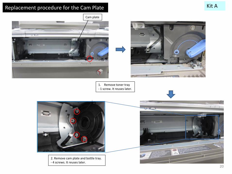
Cam plate
1. Remove toner tray - 1 screw. It reuses later.
2. Remove cam plate and bottle tray. - 4 screws. It reuses later.
Kit A
20

3. Remove cam plate - E-ring
4. Attach new cam plate to tray. - E-ring
Replacement procedure for the Cam Plate Kit A
21

5. Attach cam plate and bottle tray to hopper unit. - 4 Screws. Note: Red circle part is “boss”. Confirm the cam plate fits in to boss. And confirm tray doesn’t run onto the rail of the Hopper frame.
6. Attach the remaining parts. Note: Operate lever to confirm the operation of cam plate, bottle tray.
Replacement procedure for the Cam Plate Kit A
22

Off-Set Prints and Copies
Symptom:
Backside of paper becomes stained when printing.
Cause:
Since Toner [3] placed on paper [2] is also negatively charged, Toner [3] repels against the Pressure Roller, and then flies to and adheres to the Fixing Roller [4] before the paper [2] enters into the nip between the Fixing Roller [4] and the Pressure Roller [1] (Figure 2). Offset Toner is removed by the Cleaning Web, but a part of Offset Toner escapes through the Cleaning Web and persists on the Fixing Roller [4]. This escaped toner [5] is transferred to the Pressure Roller [1] at sheet to sheet interval and accumulates there. Toner [6] accumulated on the Pressure Roller [1] is heated up and adheres to the backside of the paper [2], which causes the backside stain (Figure 3).
Factory:
Diodes [7] and [8] were added to the electrical potential surfaces of the Fixing Assembly. The Fixing Roller [4] and the Pressure Roller [1] are adjusted so that the Pressure Roller [1] is made positively charged. The electrical potential on toner is negatively charged causing the toner to be drawn towards the Pressure Roller [1]. Therefore, toner does not fly to the Fixing Roller [4], which prevents Offset Toner from occurring.
23
Kit A
Parts Information: FIXING DIODE ASSEMBLY, LOWER FM1-B151-000 CLAW STOPPER UNIT, REAR FM3-7350-000 DUCT, FIXING, LOWER FC9-8847-000

Off-Set Prints and Copies
Service work: If the above symptom occurs, follow the steps below.
A. Replacing the Rear Claw Stopper Unit. B. Removing the Static Charge Eliminator on the Fixing Roller side C. Replacing the Lower Fixing Diode Assembly. D. Reassembling the removed parts
Note: Sufficient effects cannot be obtained from the countermeasure against Backside Stain only by adding the Diodes to the Fixing
Assembly in accordance with the steps A and C mentioned above. Be sure to perform the step B for removing the Static Charge Eliminator along with the steps A and C. In addition, the same Static Charge Eliminator with the one removed in the step B is previously attached in the new type Rear Claw Stopper Unit.
The followings two (2) parts are required for the operation: Rear Claw Stopper Unit Lower Fixing Diode Assembly In addition, the new type Lower Fixing Duct may be required depending on a product type. Refer to the "point to note about service work"
described at the end. A. How to replace the Rear Claw Stopper Unit:
1. Turn off the Main Power and pull out the Fixing/ Feeder Duplexing Assembly and remove the Fixing assembly. 2. Remove the old type Rear Claw Stopper Unit (Fixing Sub Thermistor 2 Holder) and mount the new type Rear Claw Stopper Unit [B] to which the diode is attached (1 connector, edge saddle and 1 screw).
24
Kit A
Off-Set Prints and Copies
Service work:
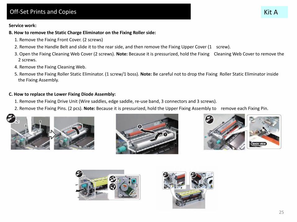
B. How to remove the Static Charge Eliminator on the Fixing Roller side:
1. Remove the Fixing Front Cover. (2 screws)
2. Remove the Handle Belt and slide it to the rear side, and then remove the Fixing Upper Cover (1 screw).
3. Open the Fixing Cleaning Web Cover (2 screws). Note: Because it is pressurized, hold the Fixing Cleaning Web Cover to remove the 2 screws.
4. Remove the Fixing Cleaning Web.
5. Remove the Fixing Roller Static Eliminator. (1 screw/1 boss). Note: Be careful not to drop the Fixing Roller Static Eliminator inside the Fixing Assembly.
C. How to replace the Lower Fixing Diode Assembly:
1. Remove the Fixing Drive Unit (Wire saddles, edge saddle, re-use band, 3 connectors and 3 screws).
2. Remove the Fixing Pins. (2 pcs). Note: Because it is pressurized, hold the Upper Fixing Assembly to remove each Fixing Pin.
25
Kit A

Off-Set Prints and Copies
Service work:
3. Disconnect the Connectors of the Heater Unit (wire saddle and 6 connectors).
4. Separate the Upper Fixing Assembly from the Lower Fixing Assembly.
5. Remove the Fixing Inlet Guide. [a] is a stepped screw and [b] is a binding screw.
6. Remove the Pressure Roller Unit.
7. Remove the Pressure Roller Static Eliminator Unit (2 screws).
8. Mount the new type Lower Fixing Diode Assembly [D] . Note: When mounting this Assembly, be sure to use the 2 screws [F] supplied together with the new type Lower Fixing Diode Assembly [D] instead of the 2 screws [E] removed in step 7 above.
26
Kit A

Off-Set Prints and Copies
Service work: D. Put the Fixing Assembly back in the Main Body after reassembling the removed parts from the Fixing Assembly. Points to note when attaching the Fixing Cleaning Web: 1. Be careful not to mistake the attaching direction of the Fixing Cleaning Web. The left below photo shows the correct direction. 2. If the Web is stained, attach the Fixing Cleaning Web after winding the Web around the Web Take-up Roller about a half turn to one
turn. Point to note about service work: When mounting the new type Lower Fixing Diode Assembly [D] , if the Lower Fixing Duct [9] is the old type [G], Lower Fixing Duct [G] and the new type Lower Fixing Diode Assembly [D] interfere with each other. In this case, remove the old type Lower Fixing Duct [G] (1 boss and 2 claws) and replace it with the new type [H].
27
Kit A

Replacement procedure for ADF 0049 JAM
New Old
New Old
FL2-9670-000
FL2-9671-000
1) Remove the front cover [1] and the rear cover [2].
2) Unscrew the 2 screws [1] to remove the left side cover [2].
3) Detach the reuse band [1] and the connector [2].
4) Detach the E-ring [1] attached on the front side of the feeder cover and the Open/Close cover stopper 1 [2].
5) Unscrew the 1 screw [1] to remove the guide pin [2] of the feeder cover and the feeder cover.
28
Kit B Parts Information: GUIDE, REGISTRATION FL2-9670-000 GUIDE, PAPER FEED FL2-9671-000

6) Open the open/close guide (lower) [1] and unscrew the 2 screws [2] to remove the registration inner guide [3].
7) Unscrew the 2 screws [1] to detach the registration guide [2]. [Caution] When attaching parts, attach the new type of the registration guide.(FL2-9670-000)
8) Unscrew the 2 screws [1] to detach the Paper feed guide assembly 2 [2].
9) Detach the plastic E-ring attached to the shaft of the Paper feed guide assembly 1 with fingers.
29
Replacement procedure for ADF 0049 JAM Kit B
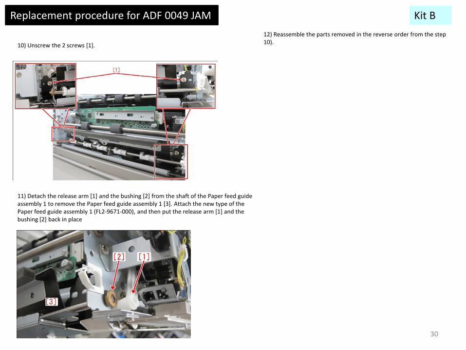
10) Unscrew the 2 screws [1].
11) Detach the release arm [1] and the bushing [2] from the shaft of the Paper feed guide assembly 1 to remove the Paper feed guide assembly 1 [3]. Attach the new type of the Paper feed guide assembly 1 (FL2-9671-000), and then put the release arm [1] and the bushing [2] back in place
12) Reassemble the parts removed in the reverse order from the step 10).
30
Replacement procedure for ADF 0049 JAM Kit B

ADF Shaft Broken
Symptom:
When the White Sheet Ratchet "A" [2] is pushed to close to the White Plate Assembly (Figure 1), the Ratchet Rotation Shaft [1] may break.
Cause:
The White Sheet Ratchet A [2] and the White Sheet Ratchet B [3] are fixed to the Ratchet Rotation Shaft [1].Therefore, if the White Plate Assembly is closed by holding the White Sheet Ratchet A [2], the overload to the Ratchet Rotation Shaft [1] may break the Ratchet Rotation Shaft [1].
Factory:
To prevent damage to the Ratchet Rotation Shaft [1] the shape of the White Sheet Ratchet A [2] and the White Sheet Ratchet B [3] have been modified in order to make them movable.
31
Kit B
Parts Information: RATCHET, SHEET, WHITE A FC8-5921-000 RATCHET, SHEET, WHITE B FC8-5920-000

4. Replacement procedure for ADF shaft broken countermeasure parts
1. Open ADF 2. Open ADF white sheet pressure panel 3. Remove shaft (Spring 2pcs and e-ring 2pcs) 4. Replace white sheet ratchet A and B to new one.
FC8-5921-000
New Old
FC8-5920-000
New Old
RATCHET, SHEET, WHITE A
RATCHET, SHEET, WHITE B
Spring, e-ring Spring, e-ring
32
Kit B

0113/0213 Jam Code
Symptom: 0113 Jam or 0213 jam may occur while the machine is in operation.0113 Jam : Outer delivery sensor delay jam0213 Jam : Outer delivery sensor stationary jam Cause: The Bushings [4] made of powdered metal are used in the delivery reverse drive unit [2] at the delivery reverse drive assembly [1]. And they [4] are also used in the reverse paper delivery assembly [3]. The sliding level of these bushings [4] is deteriorated because of the operation of the machine. As a result, the motor of the delivery reverse drive assembly [1] is put under an excessive load, causing 0113/ 0213 jams occur. Factory: To prevent damage to the Ratchet Rotation Shaft [1] the shape of the White Sheet Ratchet A [2] and the White Sheet Ratchet B [3] have been modified in order to make them movable.
33
Kit B
Parts Information: DELIVERY REVERSE DRIVE UNIT FM4-5138-010 BEARING, BALL, MF128ZZ-3 XG9-0709-000

0113 JAM countermeasure parts installation procedure
5. Remove outer paper delivery assembly.
A. Replace delivery reverse drive unit
1. Disconnect main body and accessories.
2. Remove box cover
Screws x3 Connector x1
Screw x1
4. Remove left cover
3. Remove rear cover and rear lower cover.
Kit B
34

6. Remove motor driver PCB unit 7. Remove duct (upper and lower)
Screws x2 Screws x5
You can complete installation without controller box removing. But we recommend to remove controller box, serviceability point of view.
Controller Box
0113 JAM countermeasure parts installation procedure Kit B
35

8. Remove connector support plate 9. Remove screws at harness guide that is located at upper and lower of drive motor.
Remove 3 screws
Screws x3
0113 JAM countermeasure parts installation procedure Kit B
36
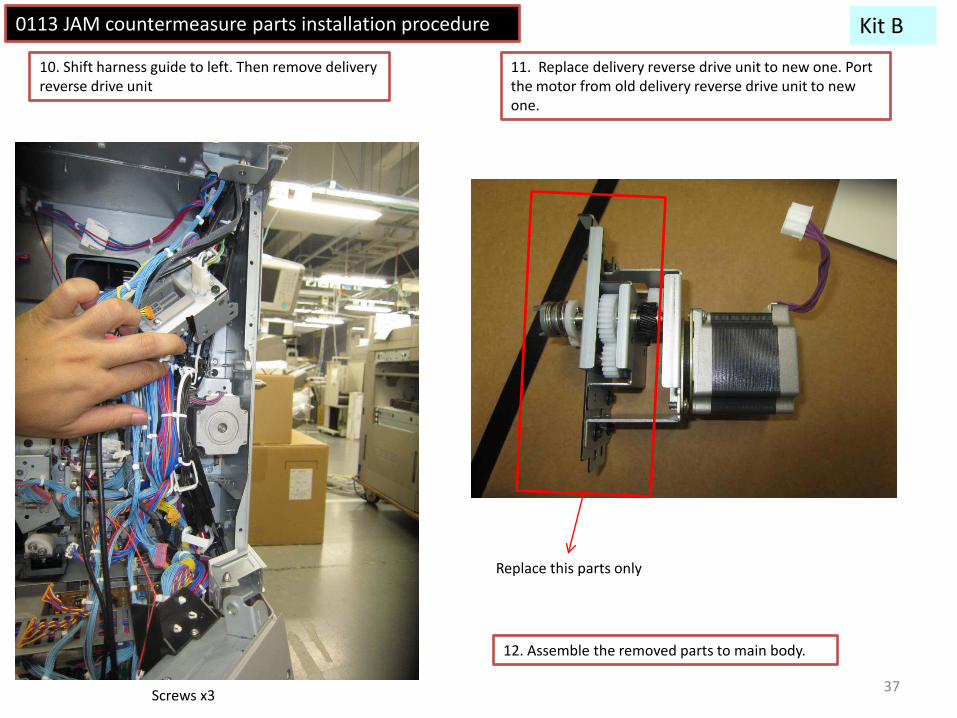
10. Shift harness guide to left. Then remove delivery reverse drive unit
11. Replace delivery reverse drive unit to new one. Port the motor from old delivery reverse drive unit to new one.
Replace this parts only
12. Assemble the removed parts to main body.
Screws x3
Kit B 0113 JAM countermeasure parts installation procedure
37

B. Replace bearing at delivery unit
Remove 2 screws from Delivery door
2-1. Pull out the Fixing Feed Unit
0113 JAM countermeasure parts installation procedure Kit B
38

2-3
Front Rear
Remove 3 gears
2-2
Rear
Replace bearing to new one (XG9-0709-000) at both front and rear.
Kit B 0113 JAM countermeasure parts installation procedure
39

Completed
40
Top Related