


Languages
Pages
Legal

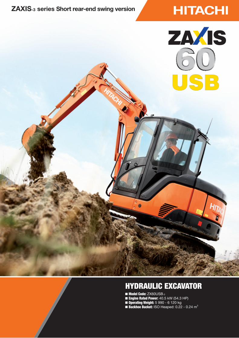
HYDRAULIC EXCAVATORModel Code: ZX60USB-3
Engine Rated Power: 40.5 kW (54.3 HP)Operating Weight: 5 990 - 6 120 kgBackhoe Bucket: ISO Heaped: 0.22 - 0.24 m3
ZAXIS-3 series Short rear-end swing version
2
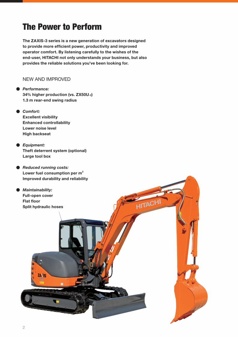
The Power to PerformThe ZAXIS-3 series is a new generation of excavators designed to provide more effi cient power, productivity and improved operator comfort. By listening carefully to the wishes of the end-user, HITACHI not only understands your business, but also provides the reliable solutions you’ve been looking for.
Performance:34% higher production (vs. ZX50U-2)1.3 m rear-end swing radius
Comfort:Excellent visibilityEnhanced controllabilityLower noise levelHigh backseat
Equipment:Theft deterrent system (optional)Large tool box
Reduced running costs:Lower fuel consumption per m3
Improved durability and reliability
Maintainability:Full-open coverFlat fl oorSplit hydraulic hoses
NEW AND IMPROVED
3
Notes: Some of the pictures in this brochure show an unmanned machine with attachments in an operating position. These were taken for demonstration purposes only and the actions shown are not recommended under normal operating conditions.
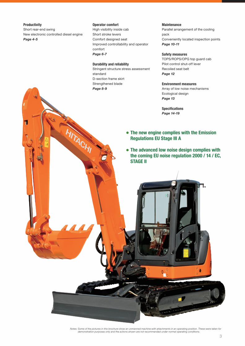
The new engine complies with the Emission Regulations EU Stage III A
The advanced low noise design complies with the coming EU noise regulation 2000 / 14 / EC, STAGE II
Operator comfortHigh visibility inside cab
Short stroke levers
Comfort designed seat
Improved controllability and operator
comfort
Page 6-7
Durability and reliabilityStringent structure stress assessment
standard
D-section frame skirt
Strengthened blade
Page 8-9
MaintenanceParallel arrangement of the cooling
pack
Conveniently located inspection points
Page 10-11
Safety measuresTOPS/ROPS/OPG top guard cab
Pilot control shut-off lever
Recoiled seat belt
Page 12
Environment measuresArray of low noise mechanisms
Ecological design
Page 13
Specifi cationsPage 14-19
ProductivityShort rear-end swing
New electronic controlled diesel engine
Page 4-5
4
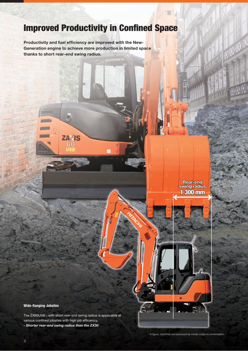
Rear-end Rear-end swing radiusswing radius1 300 mm1 300 mm
* In fi gure, machines are expressed by model codes for presentation.
Wide-Ranging Jobsites
The ZX60USB-3 with short rear-end swing radius is applicable at
various confi ned jobsites with high job effi ciency.
- Shorter rear-end swing radius than the ZX30
Improved Productivity in Confi ned SpaceProductivity and fuel effi ciency are improved with the New-Generation engine to achieve more production in limited space thanks to short rear-end swing radius.

5
Improved Productivity
Productivity is improved with increasing
actuator speeds by using the new-
generation engine.
34%* More Production (vs. ZX50U-2)* Varies depending on job conditions.
Powerful Operation (in P mode)
Earth-moving volume can be increased
with less fuel consumption in the
P mode.
15%* Higher Fuel Effi ciency (vs.
ZX50U-2) in Dump Truck Loading* Varies depending on jobs conditions.
OHV 4-Valve Engine
40.5 kW (54.3 HP) / 2000 min-1 (rpm)
The OHV 4-valve/4-cylinder engine
yields plenty of power for higher
production with less fuel consumption.
Fuel Injection System with Electronic Governor
The electronic governor is adopted
for precision control of fuel injection
timing and amount to suit the World
Emission Regulations Tier 3 and Stage
III A. This can produce plenty of power,
and reduce fuel consumption and PM
(Particulate Matter) emission due to
incomplete combustion.
EGR* System
Exhaust gas is partially mixed with
suction air for re-combustion. This
can control the oxygen density in the
combustion chamber to reduce NOx
(Nitrogen Oxides) emission while
yielding high output.
* Exhaust Gas Recirculation
Higher Production with Less Fuel Consumption
Clean and Powerful New-Generation Engine

6
Enhanced Operator ComfortOperator amenity, enhanced with better visibility and roomy space, makes possible more pleasant operation with less fatigue.
7
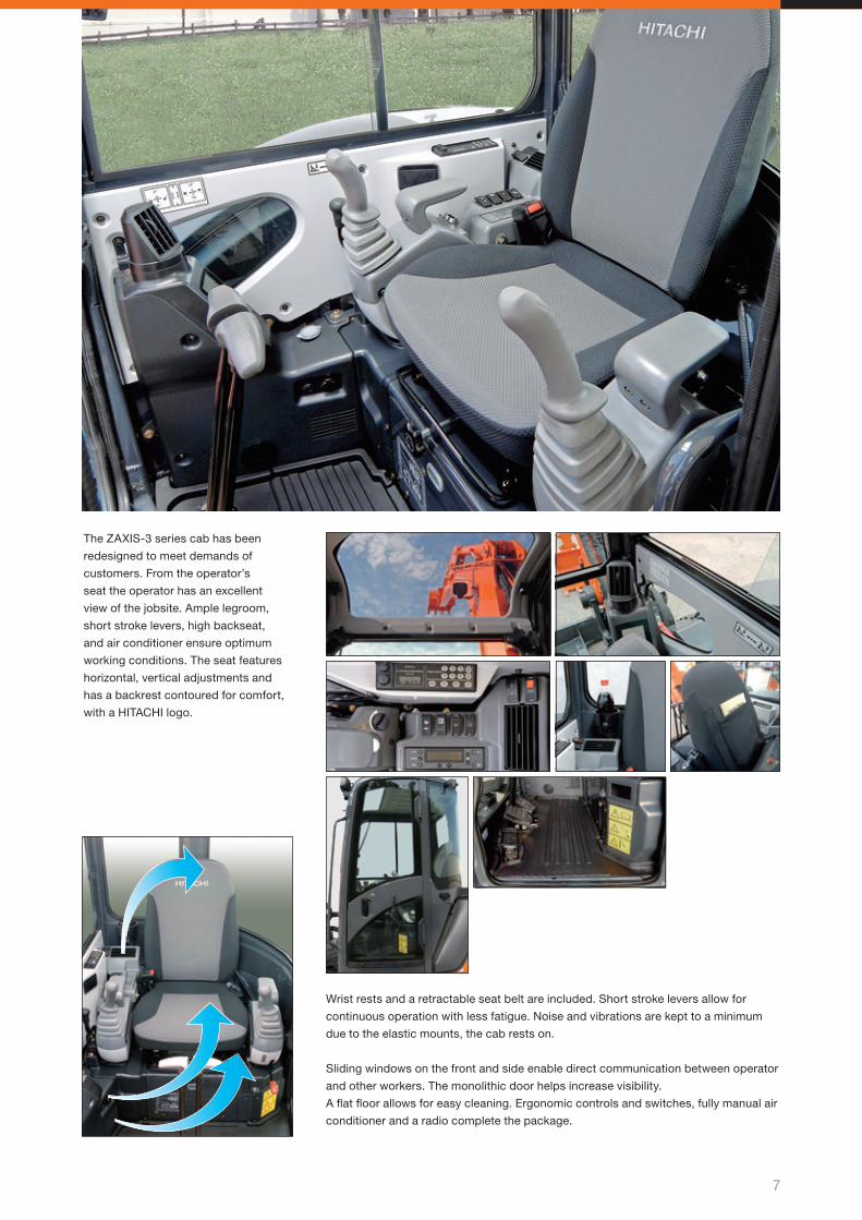
The ZAXIS-3 series cab has been
redesigned to meet demands of
customers. From the operator’s
seat the operator has an excellent
view of the jobsite. Ample legroom,
short stroke levers, high backseat,
and air conditioner ensure optimum
working conditions. The seat features
horizontal, vertical adjustments and
has a backrest contoured for comfort,
with a HITACHI logo.
Wrist rests and a retractable seat belt are included. Short stroke levers allow for
continuous operation with less fatigue. Noise and vibrations are kept to a minimum
due to the elastic mounts, the cab rests on.
Sliding windows on the front and side enable direct communication between operator
and other workers. The monolithic door helps increase visibility.
A fl at fl oor allows for easy cleaning. Ergonomic controls and switches, fully manual air
conditioner and a radio complete the package.
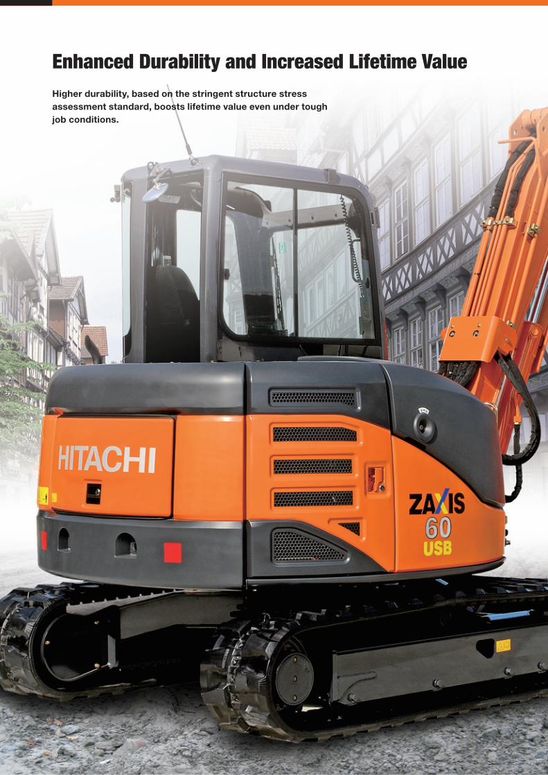
Enhanced Durability and Increased Lifetime ValueHigher durability, based on the stringent structure stress assessment standard, boosts lifetime value even under tough job conditions.
88
9
The D-section frame skirt has been proven for high rigidity of the upperstructure.
The box-section stay is utilized at the blade for higher durability.
One-piece boom swing post can reduce jerking effectively.
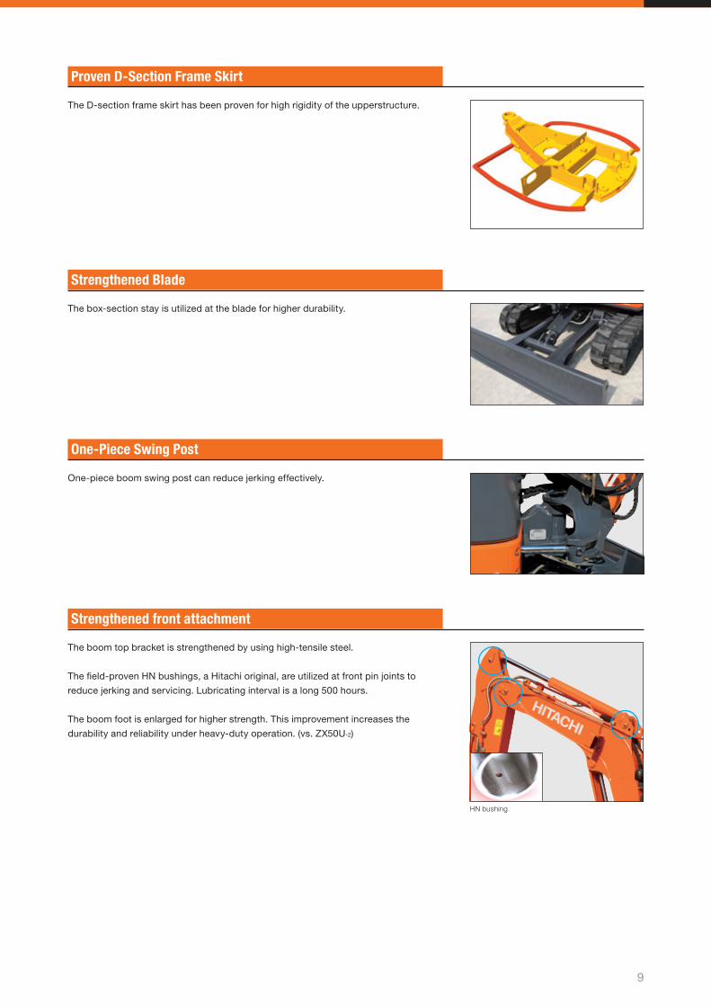
The boom top bracket is strengthened by using high-tensile steel.
The fi eld-proven HN bushings, a Hitachi original, are utilized at front pin joints to
reduce jerking and servicing. Lubricating interval is a long 500 hours.
The boom foot is enlarged for higher strength. This improvement increases the
durability and reliability under heavy-duty operation. (vs. ZX50U-2)
HN bushing
Proven D-Section Frame Skirt
Strengthened Blade
One-Piece Swing Post
Strengthened front attachment
10
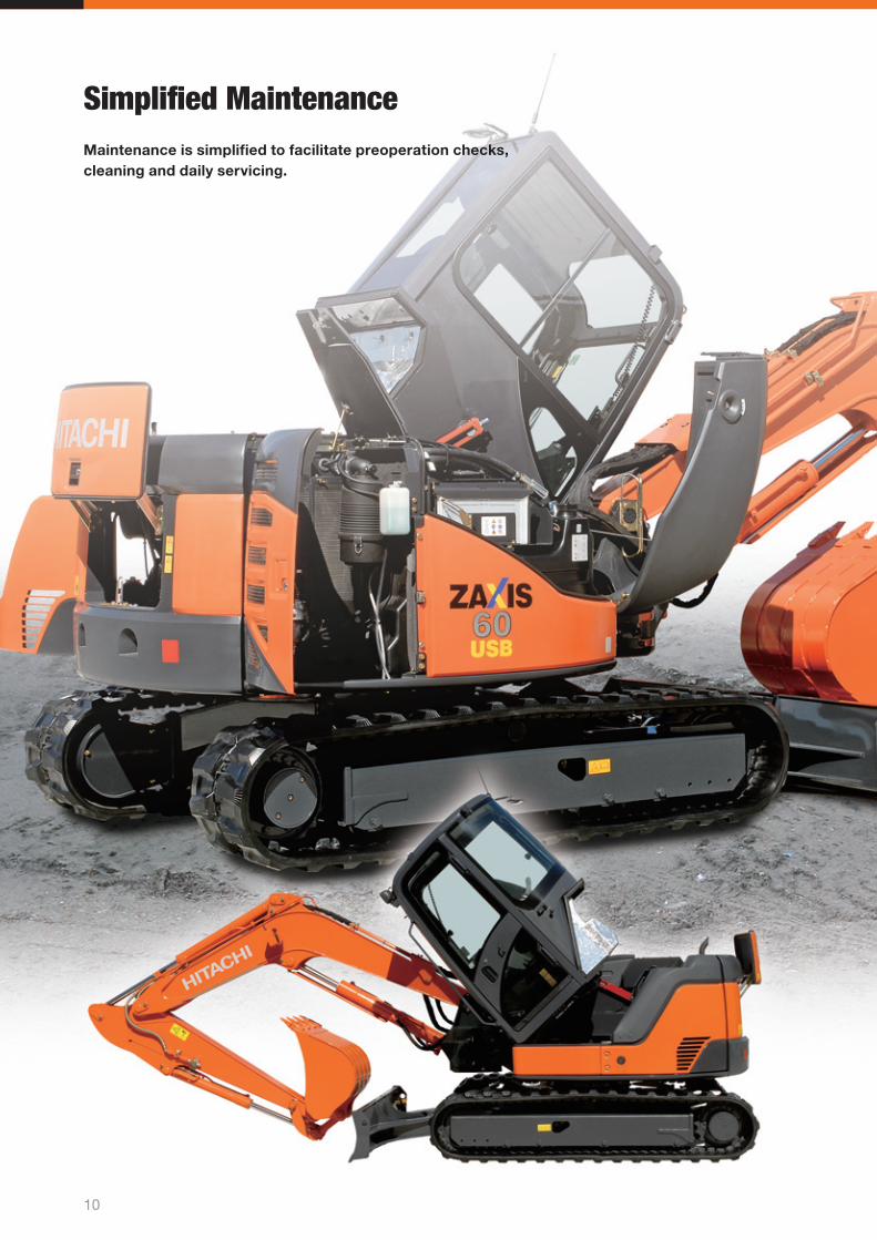
Simplifi ed MaintenanceMaintenance is simplifi ed to facilitate preoperation checks, cleaning and daily servicing.
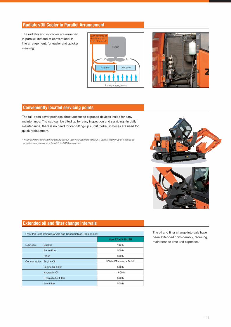
Easy removal of debris and dirt from blower, etc.
Engine
Radiator Oil Cooler
Parallel Arrangement
11
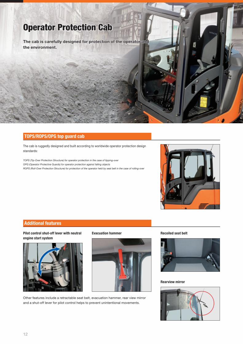
The full-open cover provides direct access to exposed devices inside for easy
maintenance. The cab can be tilted up for easy inspection and servicing. (In daily
maintenance, there is no need for cab tilting-up.) Split hydraulic hoses are used for
quick replacement.
* When using the fl oor tilt mechanism, consult your nearest Hitachi dealer. If bolts are removed or installed by
unauthorized personnel, mismatch to ROPS may occur.
The oil and fi lter change intervals have
been extended considerably, reducing
maintenance time and expenses.
The radiator and oil cooler are arranged
in parallel, instead of conventional in-
line arrangement, for easier and quicker
cleaning.
Radiator/Oil Cooler in Parallel Arrangement
Conveniently located servicing points
Extended oil and fi lter change intervals
Front Pin Lubricating Intervals and Consumables Replacement
New ZAXIS 60USB
Lubricant Bucket 100 h
Boom Foot 500 h
Front 500 h
Consumables Engine Oil 500 h (CF class or DH-1)
Engine Oil Filter 500 h
Hydraulic Oil 1 000 h
Hydraulic Oil Filter 500 h
Fuel Filter 500 h
Pilot control shut-off lever with neutral engine start system
Evacuation hammer
Other features include a retractable seat belt, evacuation hammer, rear view mirror
and a shut-off lever for pilot control helps to prevent unintentional movements.
Recoiled seat belt
Rearview mirror
12
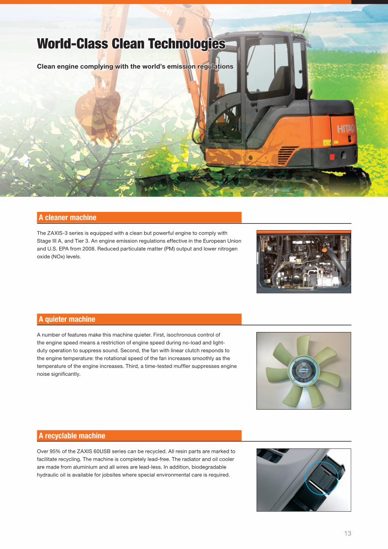
The cab is ruggedly designed and built according to worldwide operator protection design
standards:
TOPS (Tip-Over Protection Structure) for operator protection in the case of tipping-over
OPG (Operator Protective Guards) for operator protection against falling objects
ROPS (Roll-Over Protection Structure) for protection of the operator held by seat belt in the case of rolling-over
Operator Protection CabOperator Protection CabThe cab is carefully designed for protection of the operator and The cab is carefully designed for protection of the operator and the environment.the environment.
TOPS/ROPS/OPG top guard cab
Additional features
13
The ZAXIS-3 series is equipped with a clean but powerful engine to comply with
Stage III A, and Tier 3. An engine emission regulations effective in the European Union
and U.S. EPA from 2008. Reduced particulate matter (PM) output and lower nitrogen
oxide (NOx) levels.
Over 95% of the ZAXIS 60USB series can be recycled. All resin parts are marked to
facilitate recycling. The machine is completely lead-free. The radiator and oil cooler
are made from aluminium and all wires are lead-less. In addition, biodegradable
hydraulic oil is available for jobsites where special environmental care is required.
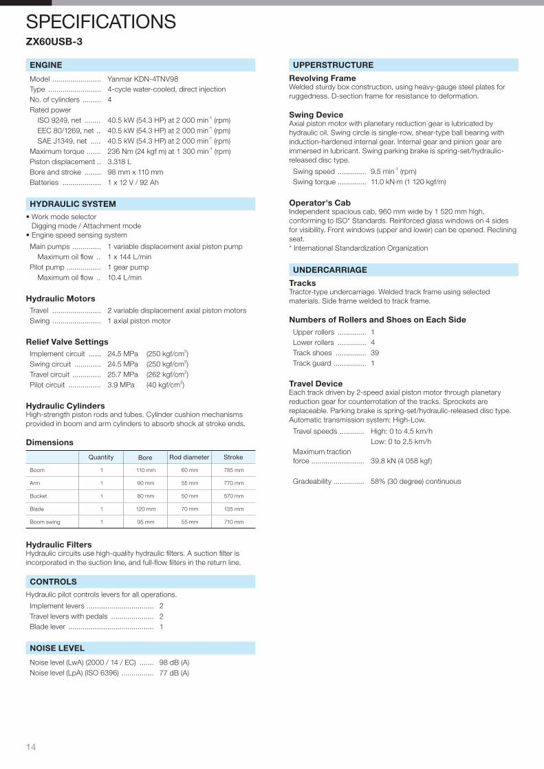
A number of features make this machine quieter. First, isochronous control of
the engine speed means a restriction of engine speed during no-load and light-
duty operation to suppress sound. Second, the fan with linear clutch responds to
the engine temperature: the rotational speed of the fan increases smoothly as the
temperature of the engine increases. Third, a time-tested muffl er suppresses engine
noise signifi cantly.
World-Class Clean TechnologiesWorld-Class Clean TechnologiesClean engine complying with the world’s emission regulationsClean engine complying with the world’s emission regulations
A cleaner machine
A quieter machine
A recyclable machine
ENGINE
Model ........................ Yanmar KDN-4TNV98Type .......................... 4-cycle water-cooled, direct injectionNo. of cylinders ......... 4Rated power
ISO 9249, net ........ 40.5 kW (54.3 HP) at 2 000 min-1 (rpm)EEC 80/1269, net .. 40.5 kW (54.3 HP) at 2 000 min-1 (rpm)SAE J1349, net ..... 40.5 kW (54.3 HP) at 2 000 min-1 (rpm)
Maximum torque ....... 236 Nm (24 kgf m) at 1 300 min-1 (rpm)Piston displacement .. 3.318 LBore and stroke ........ 98 mm x 110 mmBatteries ................... 1 x 12 V / 92 Ah
HYDRAULIC SYSTEM
• Work mode selectorDigging mode / Attachment mode
• Engine speed sensing system
Main pumps .............. 1 variable displacement axial piston pumpMaximum oil fl ow .. 1 x 144 L/min
Pilot pump ................. 1 gear pumpMaximum oil fl ow .. 10.4 L/min
Hydraulic MotorsTravel ........................ 2 variable displacement axial piston motorsSwing ........................ 1 axial piston motor
Relief Valve SettingsImplement circuit ...... 24.5 MPa (250 kgf/cm2)Swing circuit ............. 24.5 MPa (250 kgf/cm2)Travel circuit .............. 25.7 MPa (262 kgf/cm2)Pilot circuit ................ 3.9 MPa (40 kgf/cm2)
Hydraulic CylindersHigh-strength piston rods and tubes. Cylinder cushion mechanisms provided in boom and arm cylinders to absorb shock at stroke ends.
Dimensions
Quantity Bore Rod diameter Stroke
Boom 1 110 mm 60 mm 785 mm
Arm 1 90 mm 55 mm 770 mm
Bucket 1 80 mm 50 mm 570 mm
Blade 1 120 mm 70 mm 135 mm
Boom swing 1 95 mm 55 mm 710 mm
Hydraulic FiltersHydraulic circuits use high-quality hydraulic fi lters. A suction fi lter is incorporated in the suction line, and full-fl ow fi lters in the return line.
CONTROLS
Hydraulic pilot controls levers for all operations.
Implement levers ................................. 2Travel levers with pedals ..................... 2Blade lever .......................................... 1
NOISE LEVEL
Noise level (LwA) (2000 / 14 / EC) ....... 98 dB (A)Noise level (LpA) (ISO 6396) ................ 77 dB (A)
UPPERSTRUCTURE
Revolving FrameWelded sturdy box construction, using heavy-gauge steel plates for ruggedness. D-section frame for resistance to deformation.
Swing DeviceAxial piston motor with planetary reduction gear is lubricated by hydraulic oil. Swing circle is single-row, shear-type ball bearing with induction-hardened internal gear. Internal gear and pinion gear are immersed in lubricant. Swing parking brake is spring-set/hydraulic-released disc type.
Swing speed .............. 9.5 min-1 (rpm)Swing torque .............. 11.0 kN·m (1 120 kgf/m)
Operator's CabIndependent spacious cab, 960 mm wide by 1 520 mm high, conforming to ISO* Standards. Reinforced glass windows on 4 sides for visibility. Front windows (upper and lower) can be opened. Reclining seat.* International Standardization Organization
UNDERCARRIAGE
TracksTractor-type undercarriage. Welded track frame using selected materials. Side frame welded to track frame.
Numbers of Rollers and Shoes on Each SideUpper rollers .............. 1Lower rollers .............. 4Track shoes ............... 39Track guard ................ 1
Travel DeviceEach track driven by 2-speed axial piston motor through planetary reduction gear for counterrotation of the tracks. Sprockets are replaceable. Parking brake is spring-set/hydraulic-released disc type.Automatic transmission system: High-Low.
Travel speeds ............ High: 0 to 4.5 km/hLow: 0 to 2.5 km/h
Maximum traction force .......................... 39.8 kN (4 058 kgf)
Gradeability ............... 58% (30 degree) continuous
14
SPECIFICATIONSZX60USB-3
1515
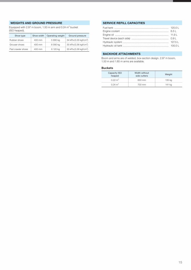
WEIGHTS AND GROUND PRESSUREEquipped with 2.97 m boom, 1.50 m arm and 0.24 m3 bucket (ISO heaped).
Shoe type Shoe width Operating weight Ground pressure
Rubber shoes 400 mm 5 990 kg 34 kPa (0.35 kgf/cm2)
Grouser shoes 400 mm 6 090 kg 35 kPa (0.36 kgf/cm2)
Pad crawler shoes 400 mm 6 120 kg 35 kPa (0.36 kgf/cm2)
SERVICE REFILL CAPACITIES
Fuel tank ............................................................................ 120.0 LEngine coolant ................................................................... 6.5 LEngine oil ........................................................................... 11.9 LTravel device (each side) .................................................... 0.9 LHydraulic system ................................................................ 127.5 LHydraulic oil tank ................................................................ 100.0 L
BACKHOE ATTACHMENTSBoom and arms are of welded, box-section design. 2.97 m boom, 1.50 m and 1.85 m arms are available.
Buckets
Capacity ISO heaped
Width without side cutters
Weight
0.22 m3 650 mm 135 kg
0.24 m3 700 mm 141 kg
16
A
A’
E
G
HK
J
I
D
B
C
F
L L’
A
B
P
Q
CN
D/D'
F
O
G
HI
J/K
E L
M
Ground Line
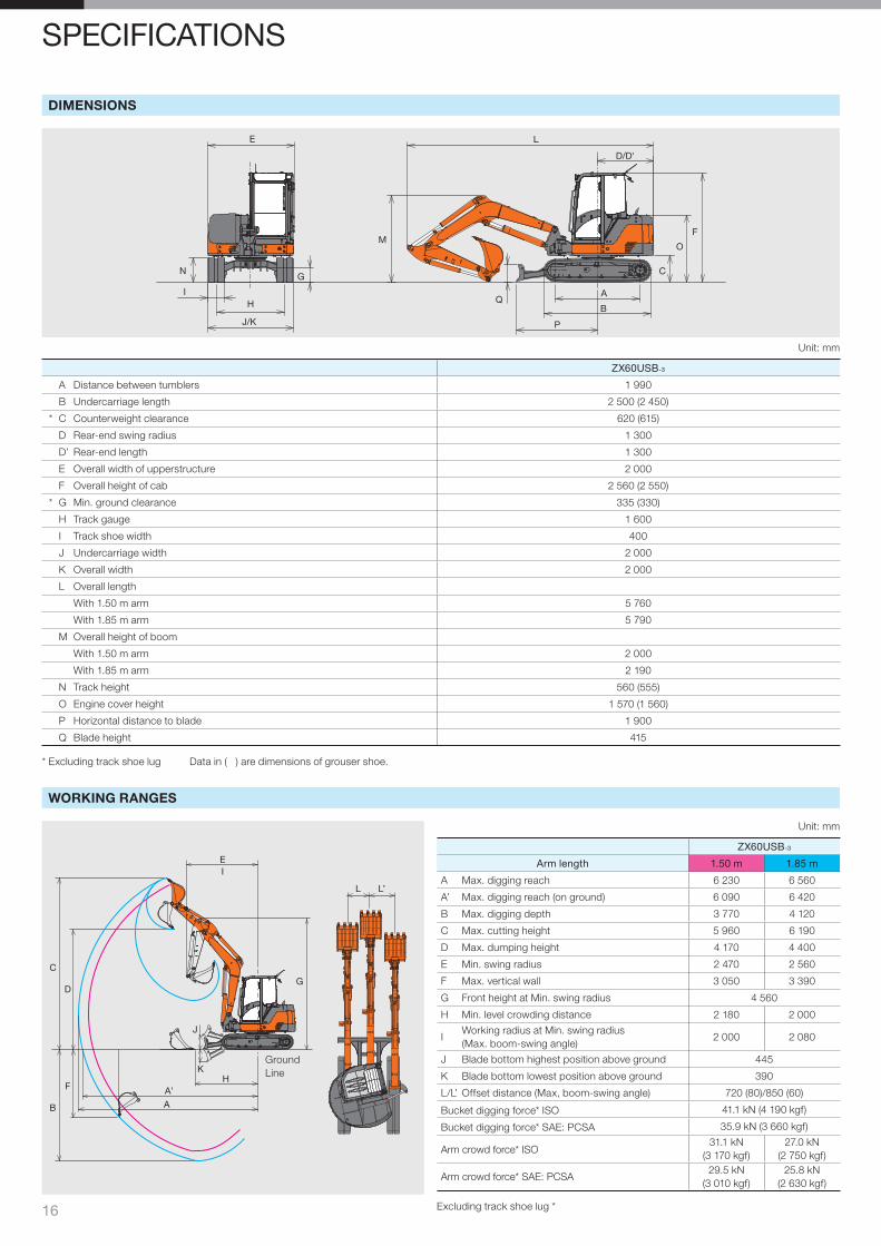
SPECIFICATIONS
DIMENSIONS
WORKING RANGES
Unit: mm
ZX60USB-3
A Distance between tumblers 1 990
B Undercarriage length 2 500 (2 450)
* C Counterweight clearance 620 (615)
D Rear-end swing radius 1 300
D’ Rear-end length 1 300
E Overall width of upperstructure 2 000
F Overall height of cab 2 560 (2 550)
* G Min. ground clearance 335 (330)
H Track gauge 1 600
I Track shoe width 400
J Undercarriage width 2 000
K Overall width 2 000
L Overall length
With 1.50 m arm 5 760
With 1.85 m arm 5 790
M Overall height of boom
With 1.50 m arm 2 000
With 1.85 m arm 2 190
N Track height 560 (555)
O Engine cover height 1 570 (1 560)
P Horizontal distance to blade 1 900
Q Blade height 415
* Excluding track shoe lug Data in ( ) are dimensions of grouser shoe.
Unit: mm
ZX60USB-3
Arm length 1.50 m 1.85 m
A Max. digging reach 6 230 6 560
A’ Max. digging reach (on ground) 6 090 6 420
B Max. digging depth 3 770 4 120
C Max. cutting height 5 960 6 190
D Max. dumping height 4 170 4 400
E Min. swing radius 2 470 2 560
F Max. vertical wall 3 050 3 390
G Front height at Min. swing radius 4 560
H Min. level crowding distance 2 180 2 000
IWorking radius at Min. swing radius(Max. boom-swing angle)
2 000 2 080
J Blade bottom highest position above ground 445
K Blade bottom lowest position above ground 390
L/L’ Offset distance (Max, boom-swing angle) 720 (80)/850 (60)
Bucket digging force* ISO 41.1 kN (4 190 kgf)
Bucket digging force* SAE: PCSA 35.9 kN (3 660 kgf)
Arm crowd force* ISO31.1 kN
(3 170 kgf)27.0 kN
(2 750 kgf)
Arm crowd force* SAE: PCSA29.5 kN
(3 010 kgf)25.8 kN
(2 630 kgf)
Excluding track shoe lug *
17
A
B
C
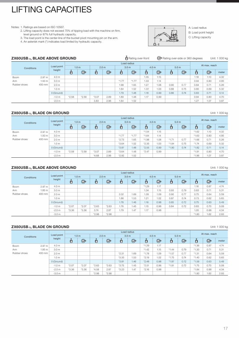
ZX60USB-3, BLADE ABOVE GROUND Rating over-front Rating over-side or 360 degrees Unit: 1 000 kg
ConditionsLoad point
height
Load radiusAt max. reach
1.0 m 2.0 m 3.0 m 4.0 m 5.0 m
meter
Boom 2.97 m
Arm 1.50 m
Rubber shoes 400 mm
4.0 m 1.35 1.15 1.18 1.10 4.32
3.0 m *1.77 *1.77 1.33 1.14 0.94 0.80 4.95
2.0 m 1.98 1.65 1.27 1.08 0.90 0.77 0.84 0.71 5.26
1.0 m 1.84 1.52 1.22 1.03 0.88 0.75 0.80 0.69 5.32
0 (Ground) 1.79 1.48 1.18 0.99 0.86 0.74 0.83 0.71 5.14
-1.0 m *2.58 *2.58 *3.07 2.89 1.80 1.48 1.17 0.99 0.94 0.80 4.70
-2.0 m 3.83 2.96 1.84 1.52 1.27 1.07 3.87
ZX60USB-3, BLADE ON GROUND Unit: 1 000 kg
ConditionsLoad point
height
Load radiusAt max. reach
1.0 m 2.0 m 3.0 m 4.0 m 5.0 m
meter
Boom 2.97 m
Arm 1.50 m
Rubber shoes 400 mm
4.0 m *1.54 1.15 *1.62 1.10 4.32
3.0 m *1.77 *1.77 *1.64 1.14 *1.63 0.80 4.95
2.0 m *2.73 1.65 *1.98 1.08 *1.71 0.77 *1.66 0.71 5.26
1.0 m *3.64 1.52 *2.35 1.03 *1.84 0.75 *1.74 0.69 5.32
0 (Ground) *3.87 1.48 *2.55 0.99 *1.90 0.74 *1.82 0.71 5.14
-1.0 m *2.58 *2.58 *3.07 2.89 *3.64 1.48 *2.47 0.99 *1.91 0.80 4.70
-2.0 m *4.68 2.96 *2.92 1.52 *1.96 1.07 3.87
LIFTING CAPACITIES
ZX60USB-3, BLADE ABOVE GROUND Unit: 1 000 kg
ConditionsLoad point
height
Load radiusAt max. reach
1.0 m 2.0 m 3.0 m 4.0 m 5.0 m
meter
Boom 2.97 m
Arm 1.85 m
Rubber shoes 400 mm
4.0 m *1.29 1.17 1.16 0.87 4.74
3.0 m 1.34 1.15 0.93 0.79 0.83 0.71 5.31
2.0 m 2.02 1.69 1.28 1.09 0.90 0.77 0.75 0.64 5.59
1.0 m 1.86 1.53 1.21 1.02 0.87 0.74 0.73 0.62 5.65
0 (Ground) 1.78 1.46 1.16 0.98 0.85 0.72 0.75 0.63 5.49
-1.0 m *2.07 *2.07 *2.63 *2.63 1.76 1.45 1.15 0.96 0.84 0.72 0.83 0.70 5.08
-2.0 m *3.36 *3.36 3.74 2.87 1.79 1.47 1.17 0.98 1.05 0.88 4.34
-3.0 m *2.98 *2.98 *1.80 1.62 2.93
ZX60USB-3, BLADE ON GROUND Unit: 1 000 kg
ConditionsLoad point
height
Load radiusAt max. reach
1.0 m 2.0 m 3.0 m 4.0 m 5.0 m
meter
Boom 2.97 m
Arm 1.85 m
Rubber shoes 400 mm
4.0 m *1.29 1.17 *1.36 0.87 4.74
3.0 m *1.42 1.15 *1.44 0.79 *1.30 0.71 5.31
2.0 m *2.31 1.69 *1.78 1.09 *1.57 0.77 *1.31 0.64 5.59
1.0 m *3.35 1.53 *2.19 1.02 *1.75 0.74 *1.40 0.62 5.65
0 (Ground) *3.81 1.46 *2.48 0.98 *1.87 0.72 *1.59 0.63 5.49
-1.0 m *2.07 *2.07 *2.63 *2.63 *3.75 1.45 *2.51 0.96 *1.81 0.72 *1.75 0.70 5.08
-2.0 m *3.36 *3.36 *4.58 2.87 *3.23 1.47 *2.16 0.98 *1.84 0.88 4.34
-3.0 m *2.98 *2.98 *1.80 1.62 2.93
A: Load radius
B: Load point height
C: Lifting capacity
Notes: 1. Ratings are based on ISO 10567.2. Lifting capacity does not exceed 75% of tipping load with the machine on fi rm,
level ground or 87% full hydraulic capacity.3. The load point is the center-line of the bucket pivot mounting pin on the arm.4. An asterisk mark (*) indicates load limited by hydraulic capacity.
18
LIFTING CAPACITIES
A
B
C
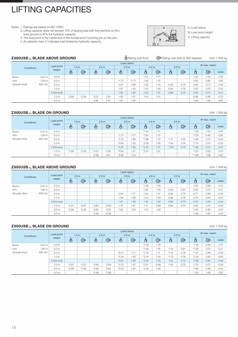
ZX60USB-3, BLADE ABOVE GROUND Rating over-front Rating over-side or 360 degrees Unit: 1 000 kg
ConditionsLoad point
height
Load radiusAt max. reach
1.0 m 2.0 m 3.0 m 4.0 m 5.0 m
meter
Boom 2.97 m
Arm 1.50 m
Grouser shoe 400 mm
4.0 m 1.37 1.17 1.20 1.03 4.32
3.0 m *1.77 *1.77 1.35 1.15 0.95 0.82 4.95
2.0 m 2.01 1.68 1.29 1.10 0.92 0.79 0.85 0.73 5.26
1.0 m 1.87 1.55 1.23 1.05 0.90 0.76 0.82 0.70 5.32
0 (Ground) 1.82 1.50 1.20 1.01 0.88 0.75 0.85 0.72 5.14
-1.0 m *2.58 *2.58 *3.07 2.95 1.83 1.51 1.19 1.01 0.96 0.82 4.70
-2.0 m 3.89 3.01 1.87 1.55 1.29 1.09 3.87
ZX60USB-3, BLADE ON GROUND Unit: 1 000 kg
ConditionsLoad point
height
Load radiusAt max. reach
1.0 m 2.0 m 3.0 m 4.0 m 5.0 m
meter
Boom 2.97 m
Arm 1.50 m
Grouser shoe 400 mm
4.0 m *1.54 1.17 *1.62 1.03 4.32
3.0 m *1.77 *1.77 *1.64 1.15 *1.63 0.82 4.95
2.0 m *2.73 1.68 *1.98 1.10 *1.71 0.79 *1.66 0.73 5.26
1.0 m *3.64 1.55 *2.35 1.05 *1.84 0.76 *1.74 0.70 5.32
0 (Ground) *3.87 1.50 *2.55 1.01 *1.90 0.75 *1.82 0.72 5.14
-1.0 m *2.58 *2.58 *3.07 2.95 *3.64 1.51 *2.47 1.01 *1.91 0.82 4.70
-2.0 m *4.68 3.01 *2.92 1.55 *1.96 1.09 3.87
ZX60USB-3, BLADE ABOVE GROUND Unit: 1 000 kg
ConditionsLoad point
height
Load radiusAt max. reach
1.0 m 2.0 m 3.0 m 4.0 m 5.0 m
meter
Boom 2.97 m
Arm 1.85 m
Grouser shoe 400 mm
4.0 m *1.29 1.19 1.03 0.89 4.74
3.0 m 1.36 1.16 0.94 0.81 0.85 0.73 5.31
2.0 m 2.05 1.71 1.30 1.11 0.92 0.79 0.77 0.66 5.59
1.0 m 1.89 1.56 1.23 1.04 0.89 0.76 0.74 0.63 5.65
0 (Ground) 1.81 1.49 1.18 1.00 0.86 0.73 0.76 0.65 5.49
-1.0 m *2.07 *2.07 *2.63 *2.63 1.79 1.47 1.17 0.98 0.86 0.73 0.84 0.72 5.08
-2.0 m *3.36 *3.36 3.80 2.93 1.82 1.50 1.19 1.00 1.06 0.90 4.34
-3.0 m *2.98 *2.98 *1.80 1.65 2.93
ZX60USB-3, BLADE ON GROUND Unit: 1 000 kg
ConditionsLoad point
height
Load radiusAt max. reach
1.0 m 2.0 m 3.0 m 4.0 m 5.0 m
meter
Boom 2.97 m
Arm 1.85 m
Grouser shoe 400 mm
4.0 m *1.29 1.19 *1.36 0.89 4.74
3.0 m *1.42 1.16 *1.44 0.81 *1.30 0.73 5.31
2.0 m *2.31 1.71 *1.78 1.11 *1.57 0.79 *1.31 0.66 5.59
1.0 m *3.35 1.56 *2.19 1.04 *1.75 0.76 *1.40 0.63 5.65
0 (Ground) *3.81 1.49 *2.48 1.00 *1.87 0.73 *1.59 0.65 5.49
-1.0 m *2.07 *2.07 *2.63 *2.63 *3.75 1.47 *2.51 0.98 *1.81 0.73 *1.75 0.72 5.08
-2.0 m *3.36 *3.36 *4.58 2.93 *3.23 1.50 *2.16 1.00 *1.84 0.90 4.34
-3.0 m *2.98 *2.98 *1.80 1.65 2.93
A: Load radius
B: Load point height
C: Lifting capacity
Notes: 1. Ratings are based on ISO 10567.2. Lifting capacity does not exceed 75% of tipping load with the machine on fi rm,
level ground or 87% full hydraulic capacity.3. The load point is the center-line of the bucket pivot mounting pin on the arm.4. An asterisk mark (*) indicates load limited by hydraulic capacity.

19
EQUIPMENT
HYDRAULIC SYSTEM
• Hydraulic pilot type control levers• Swing parking brake• Travel parking brake• Two-speed travel system• Auto-idling system• Water-separator for engine fuel
CABIN
• Pilot control shut-off lever with neutral engine start system
• ROPS/FOPS/TOPS cab• Fresh air introduction type air
conditioner• AM/FM radio• Window washer• Defroster• Ashtray• Reclining seat• Suspension seat• Auto idle• E mode• Retractable seat belt• Wrist rests• Spare power supply• Drink holder• Rearview mirror• Wiper
UNDERCARRIAGE
• 400 mm rubber shoes• Travel parking brake
UPPER STRUCTURE
• Front screens (radiator, oil cooler, air-con condenser)
• Tool box
FRONT ATTACHMENTS
• HN bushing• 1.50 m arm
STANDARD EQUIPMENT Standard equipment may vary by country, so please consult your Hitachi dealer for details.
OPTIONAL EQUIPMENT Optional equipment may vary by country, so please consult your Hitachi dealer for details.
• Air cleaner double-elements• Extra piping• Travel alarm• Auxiliary light
• Refuel pump• Auxiliary fl ow rate selector• 400 mm grouser shoes• 400 mm pad crawler shoes
• 1.50 m 4-side reinforced arm• 1.85 m arm• 1.85 m 4-side reinforced arm
• 0.22 m3 backhoe buckets (ISO Heaped)

KS-EN170EUHitachi Construction Machinerywww.hcme.com
These specifi cations are subject to change without notice. Illustrations and photos show the standard models, and may or may not include optional equipment, accessories, and all standard equipment with some differences in colour and features. Before use, read and understand the Operator’s Manual for proper operation.
Printed in the Netherlands
Top Related