


Languages
Pages
Legal


1
Hybrid APNT: Terrestrial Radionavigation to
Support Future Aviation Needs
Sherman Lo, Yu-Hsuan Chen, Shiwen Zhang, Per Enge, Stanford University
BIOGRAPHY
Sherman Lo is a senior research engineer at the Stanford
University GPS Laboratory.
Yu-Hsuan Chen is a research associate in GPS Laboratory
at Stanford University. He received his Ph.D. in electrical
engineering from National Cheng Kung University,
Taiwan in 2011.
Shiwen Zhang is a Ph.D. candidate Aeronautics &
Astronautics in GPS Laboratory at Stanford University.
Per Enge is the Vance D. and Arlene C. Coffman
Professor in the School of Engineering at Stanford
University and the director of the Stanford GPS
Laboratory.
1. INTRODUCTION
The Federal Aviation Administration (FAA) Alternative
Positioning Navigation & Timing (APNT) program is
developing and examining solutions to provide terrestrial
based radio-navigation capability that can support Next
Generation Air Transportation System (NextGen) even
with the loss of GNSS. Two technologies being
examined are improved distance measuring equipment
(DME) and passive ranging from DME and automatic
dependent surveillance broadcast (ADS-B) ground
stations. This paper details the concept and operation of
Hybrid APNT which combines these two options to form
a solution that contains the best features of each option.
Hybrid APNT combines true and passive ranging
transmissions, particularly from the same source, to allow
for the integrated use of DME and ADS-B ground stations
and improve key performance areas. The combination of
these ranging sources from the same ground station
enables synchronization of aircraft clock with the ground
and allows for interchangeable use of true and passive
ranges. The combination helps address two key
performance issues: coverage and capacity.
OUTLINE
This paper presents and details the concept of Hybrid
APNT, one of three APNT solutions being assessed by
the FAA. The background section covers the components
of hybrid APNT and the potential modification to today’s
existing systems that would enable hybrid APNT
capabilities. An important component of the Hybrid
APNT is passive ranging or pseudolites (PL). Terrestrial
pseudolites currently do not exist in the FAA navigational
infrastructure. Selected means of implementing passive
and true ranging on DME, ADS-B ground stations are
outlined.
Hybrid APNT alternative is then presented along with its
concept of operations. Hybrid APNT allows for many
operational modes which are outlined.
Finally, the benefits of hybrid APNT in terms of coverage
and capacity are analyzed. The analysis will show how
the increased coverage with different hybrid APNT over
traditional DME or pseudolites, even though the same
stations and signals are used.
2. BACKGROUND
The APNT group was formed to determine and develop
the promising solutions that provide FAA navigation,
surveillance and other services in the event of a Global
Positioning System (GPS) or GNSS degradation event
[1]. The need for APNT is particularly important as
envisioned use of GPS by aviation will increase in
coming years. Under NextGen, GPS will be the primary
means of navigation and surveillance. GPS will enable
the operations that are needed to handle the increased air
traffic levels anticipated in the 2025 time frame.
Currently, GPS is often the only system capable of
supporting many envisioned operations. Current legacy
terrestrial based navigation systems either cannot provide
the area navigation (RNAV) capabilities or the
performance needed for sustained future operations.
TARGETED PERFORMANCE
The APNT solution should sustain aviation operations in
the event of GPS unavailability. The solution will
provide RNAV capability for en route operations
throughout the conterminous United States (CONUS) as
well as terminal area coverage in major airspace. For
terminal operations, a minimum of RNAV down to 1.0
nautical mile (RNAV 1.0) is required. However, RNAV
or Required Navigation Performance (RNP) operations
down to 0.3 nautical miles (RNAV/RNP 0.3) may
desirable. Another potential target is to provide position
2
information for Automatic Dependent Surveillance -
Broadcast (ADS-B) to support 3-mile and 5-mile aircraft
separation. Currently, 3-mile separation rules require
92.6-meter position accuracy, which is a navigation
accuracy category (NACp) of 8 [2].
APNT ALTERNATIVES
Three concepts are currently being evaluated for APNT:
1) positioning based on traffic information services
broadcast (TIS-B) reports, 2) DME/DME, and 3) hybrid
APNT. In the first concept an aircraft would get its
position from ground transmitted TIS-B reports. TIS-B
position reports supplies aircraft positions as determined
by ground based surveillance - typically secondary
surveillance radar (SSR). TIS-B is an existing component
of FAA ADS-B operations. The second concept is to
improve the existing DME system with some additional
stations to cover current en route coverage gaps. Range
measurements from multiple DMEs, gathered using
scanning DME avionics, yields position and navigation
information. The final concept is the topic of this paper.
DISTANCE MEASURING EQUIPMENT (DME)
DME is an internationally accepted and adopted two-way
ranging system operating in the L-band of radio
frequencies between 960-1215 MHz. DME and TACAN
which adds an azimuth function for military users is
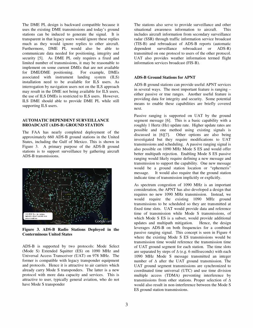
widely deployed worldwide. As seen in Figure 1, within
the United States, there are about 1100 DME or TACAN
stations that are operated.
Figure 1. DMEs and TACANs Operating in the
Conterminous United States
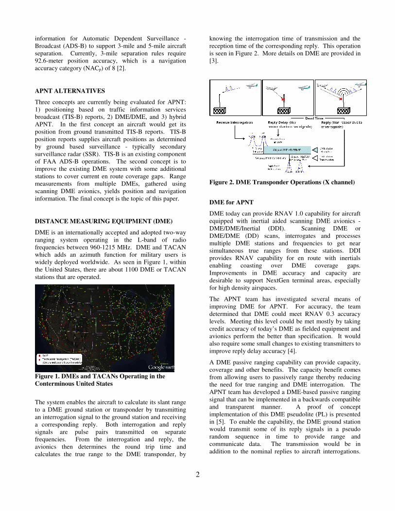
The system enables the aircraft to calculate its slant range
to a DME ground station or transponder by transmitting
an interrogation signal to the ground station and receiving
a corresponding reply. Both interrogation and reply
signals are pulse pairs transmitted on separate
frequencies. From the interrogation and reply, the
avionics then determines the round trip time and
calculates the true range to the DME transponder, by
knowing the interrogation time of transmission and the
reception time of the corresponding reply. This operation
is seen in Figure 2. More details on DME are provided in
[3].
Figure 2. DME Transponder Operations (X channel)
DME for APNT
DME today can provide RNAV 1.0 capability for aircraft
equipped with inertial aided scanning DME avionics -
DME/DME/Inertial (DDI). Scanning DME or
DME/DME (DD) scans, interrogates and processes
multiple DME stations and frequencies to get near
simultaneous true ranges from these stations. DDI
provides RNAV capability for en route with inertials
enabling coasting over DME coverage gaps.
Improvements in DME accuracy and capacity are
desirable to support NextGen terminal areas, especially
for high density airspaces.
The APNT team has investigated several means of
improving DME for APNT. For accuracy, the team
determined that DME could meet RNAV 0.3 accuracy
levels. Meeting this level could be met mostly by taking
credit accuracy of today’s DME as fielded equipment and
avionics perform the better than specification. It would
also require some small changes to existing transmitters to
improve reply delay accuracy [4].
A DME passive ranging capability can provide capacity,
coverage and other benefits. The capacity benefit comes
from allowing users to passively range thereby reducing
the need for true ranging and DME interrogation. The
APNT team has developed a DME-based passive ranging
signal that can be implemented in a backwards compatible
and transparent manner. A proof of concept
implementation of this DME pseudolite (PL) is presented
in [5]. To enable the capability, the DME ground station
would transmit some of its reply signals in a pseudo
random sequence in time to provide range and
communicate data. The transmission would be in
addition to the nominal replies to aircraft interrogations.
3
The DME PL design is backward compatible because it
uses the existing DME transmissions and today’s ground
stations can be induced to generate the signal. It is
transparent in that legacy users would ignore these replies
much as they would ignore replies to other aircraft.
Furthermore, DME PL would also be able to
communicate data needed for positioning, integrity and
security [5]. As DME PL only requires a fixed and
limited number of transmissions, it may be reasonable to
implement on some current DMEs that are not available
for DME/DME positioning. For example, DMEs
associated with instrument landing system (ILS)
installation need to be available for ILS users. As
interrogation by navigation users not on the ILS approach
may result in the DME not being available for ILS users,
the use of ILS DMEs is restricted to ILS users. However,
ILS DME should able to provide DME PL while still
supporting ILS users.
AUTOMATIC DEPENDENT SURVEILLANCE
BROADCAST (ADS-B) GROUND STATION
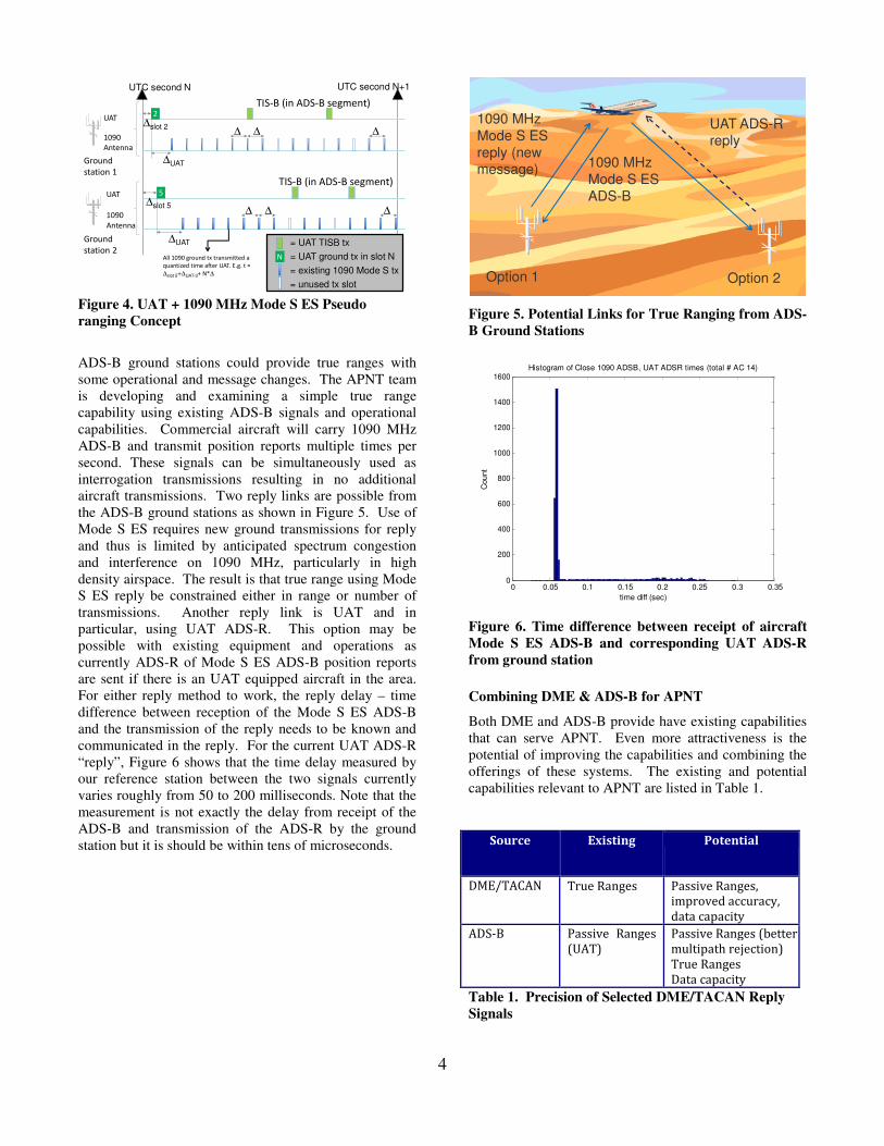
The FAA has nearly completed deployment of the
approximately 660 ADS-B ground stations in the United
States, including the Gulf of Mexico. This is shown in
Figure 3. A primary purpose of the ADS-B ground
stations is to support surveillance by gathering aircraft
ADS-B transmissions.
Figure 3. ADS-B Radio Stations Deployed in the
Conterminous United States
ADS-B is supported by two protocols: Mode Select
(Mode S) Extended Squitter (ES) on 1090 MHz and
Universal Access Transceiver (UAT) on 978 MHz. The
former is compatible with legacy transponder equipment
and protocols. Hence it is attractive to air carriers which
already carry Mode S transponders. The latter is a new
protocol with more data capacity and services. This is
attractive to user, typically general aviation, who do not
have Mode S transponder
The stations also serve to provide surveillance and other
situational awareness information to aircraft. This
includes aircraft information from secondary surveillance
radar (SSR) through traffic information service broadcast
(TIS-B) and rebroadcast of ADS-B reports (automatic
dependent surveillance rebroadcast or ADS-R)
transmitted on one protocol to users of the other protocol.
UAT also provides weather information termed flight
information services broadcast (FIS-B).
ADS-B Ground Stations for APNT
ADS-B ground stations can provide useful APNT services
in several ways. The most important feature is ranging –
either passive or true ranges. Another useful feature is
providing data for integrity and security. Some potential
means to enable these capabilities are briefly covered
next.
Passive ranging is supported on UAT by the ground
segment message [6]. This is a basic capability with a
roughly 1 Hertz (Hz) update rate. Higher update rates are
possible and one method using existing signals is
discussed in [6][7]. Other options are also being
investigated but they require modifications to UAT
transmissions and scheduling. A passive ranging signal is
also possible on 1090 MHz Mode S ES and would offer
better multipath rejection. Enabling Mode S ES passive
ranging would likely require defining a new message and
transmission to support the capability. One new message
would be a ground station location or “ephemeris”
message. It would also require that the ground station
indicate time of transmission implicitly or explicitly.
As spectrum congestion of 1090 MHz is an important
consideration, the APNT has also developed a design that
requires no new 1090 MHz transmission. Instead, we
would require the existing 1090 MHz ground
transmissions to be scheduled so they are transmitted at
fixed time slots. UAT would provide data and reference
time of transmission while Mode S transmissions, of
which Mode S ES is a subset, would provide additional
updates and multipath mitigation. Hence, the design
leverages ADS-B on both frequencies for a combined
passive ranging signal. This concept is seen in Figure 4
where the existing Mode S ES transmissions would be
transmission time would reference the transmission time
of UAT ground segment for each station. The time slots
are separated by steps of ∆ (e.g. 6 milliseconds) with each
1090 MHz Mode S message transmitted an integer
number of ∆ after the UAT ground transmission. The
UAT ground segment transmissions are synchronized to
coordinated time universal (UTC) and use time division
multiple access (TDMA) preventing interference by
transmissions from other stations. Proper selection of ∆
would also result in non-interference between the Mode S
ES ground station transmissions.
4
2UAT
1090
Antenna
5UAT
1090
Antenna
Ground
station 1
Ground
station 2
TIS-B (in ADS-B segment)
TIS-B (in ADS-B segment)
All 1090 ground tx transmitted a
quantized time after UAT. E.g. t =
∆slot 5+∆UAT-3+ N*∆
UTC second N UTC second N+1
∆UAT
∆ ∆ ∆
∆ ∆ ∆
∆slot 2
∆slot 5
∆UAT
= UAT ground tx in slot N
= existing 1090 Mode S tx
= unused tx slot
N
= UAT TISB tx
Figure 4. UAT + 1090 MHz Mode S ES Pseudo
ranging Concept
ADS-B ground stations could provide true ranges with
some operational and message changes. The APNT team
is developing and examining a simple true range
capability using existing ADS-B signals and operational
capabilities. Commercial aircraft will carry 1090 MHz
ADS-B and transmit position reports multiple times per
second. These signals can be simultaneously used as
interrogation transmissions resulting in no additional
aircraft transmissions. Two reply links are possible from
the ADS-B ground stations as shown in Figure 5. Use of
Mode S ES requires new ground transmissions for reply
and thus is limited by anticipated spectrum congestion
and interference on 1090 MHz, particularly in high
density airspace. The result is that true range using Mode
S ES reply be constrained either in range or number of
transmissions. Another reply link is UAT and in
particular, using UAT ADS-R. This option may be
possible with existing equipment and operations as
currently ADS-R of Mode S ES ADS-B position reports
are sent if there is an UAT equipped aircraft in the area.
For either reply method to work, the reply delay – time
difference between reception of the Mode S ES ADS-B
and the transmission of the reply needs to be known and
communicated in the reply. For the current UAT ADS-R
“reply”, Figure 6 shows that the time delay measured by
our reference station between the two signals currently
varies roughly from 50 to 200 milliseconds. Note that the
measurement is not exactly the delay from receipt of the
ADS-B and transmission of the ADS-R by the ground
station but it is should be within tens of microseconds.
1090 MHz
Mode S ES
ADS-B
UAT ADS-R reply
1090 MHz
Mode S ES
reply (new message)
Option 1 Option 2
Figure 5. Potential Links for True Ranging from ADS-
B Ground Stations
0 0.05 0.1 0.15 0.2 0.25 0.3 0.350
200
400
600
800
1000
1200
1400
1600Histogram of Close 1090 ADSB, UAT ADSR times (total # AC 14)
time diff (sec)
Count
Figure 6. Time difference between receipt of aircraft
Mode S ES ADS-B and corresponding UAT ADS-R
from ground station
Combining DME & ADS-B for APNT
Both DME and ADS-B provide have existing capabilities
that can serve APNT. Even more attractiveness is the
potential of improving the capabilities and combining the
offerings of these systems. The existing and potential
capabilities relevant to APNT are listed in Table 1.
Source Existing Potential
DME/TACAN True Ranges Passive Ranges,
improved accuracy,
data capacity
ADS-B Passive Ranges
(UAT) Passive Ranges (better
multipath rejection)
True Ranges
Data capacity
Table 1. Precision of Selected DME/TACAN Reply
Signals
5
Figure 7. DMEs (squares), TACANs (circles), & ADS-
B Radio Stations (pins) Deployed in the Conterminous
United States
The combined use of DME and ADS-B is attractive as it
may help significantly with key performance targets:
coverage, capacity, accuracy and integrity. Coverage is
especially challenging at low altitudes so a larger ground
station network can be very beneficial. As DME and
ADS-B ground stations are not collocated, together these
two systems provide network of roughly 1700
geographically separated ground stations within the
United States airspace. This is shown in Figure 7.
Ideally, APNT could combine DME and ADS-B ranges to
take advantage of both. This is the concept behind hybrid
APNT and there are many possibilities for hybrid APNT
to be implemented. Table 2 shows the existing systems
which cannot be easily used together and possible hybrid
APNT implementations based on improvements to DME,
ADS-B or both.
Scenario Passive
Ranging True Ranging Required
Upgrade or
Change
Existing ADS-B DME/TACAN
Hybrid APNT
using ADS-B
ADS-B DME/TACAN
ADS-B
ADS-B true
range
Hybrid APNT
using DME ADS-B
DME/TACAN
DME/TACAN DME PL
Hybrid APNT
w. ADS-B &
DME
ADS-B
DME/TACAN
DME/TACAN
ADS-B
ADS-B true
range & DME
PL
Table 2. Potential Operating Scenarios
3. HYBRID APNT CONCEPT & BENEFITS
The hybrid APNT concept combines the use of true and
passive ranges to offer advantages, particularly for
coverage and capacity, over pure true or passive ranges
alone. With the hybrid APNT infrastructure, a user can
position using passive ranges, true ranges or a
combination of these ranges. The power of hybrid APNT
concept comes from combine use of passive and true
ranges from one station. This provides both a range
measurement and synchronization of the avionics clock
with the ground. This is shown in Figure 8. The result is
that only one additional station providing any range
(passive or true) is needed for horizontal positioning.
Hence, with the envisioned infrastructure, the hybrid
APNT use of both types of ranging results for benefits
over use of true or passive ranging alone.
R1
ρ1
Figure 8. Passive & True Ranges from Same Ground
Station to Synchronize APNT avionics with Ground
For the purpose of the paper, DME ground stations are
presented as providing both true and passive ranges while
ADS-B ground stations only provide passive ranges.
However, concept is equally applicable with any of the
last three scenarios shown in Table 2. The concept
integrates naturally with the possibility of a more stable
aircraft clock to maintain synchronization with the
ground.
Concept of Operations
As multiple types and sources of ranging signals will be
transmitted, the ground infrastructure and potential
avionics can support several operational modes. Three
specific modes for hybrid APNT: 1) True ranging (DME
mode) 2) Passive ranging (PL mode) and 3) Hybrid or
mixed ranging (hybrid mode). The section will discuss
the features of each mode.
Since the DME infrastructure is a basis for hybrid APNT,
aircraft can operate using DME only. As much of the
existing commercial air fleet has installed DME/DME or
DDI avionics, this allows them to operate effectively
without new equipment. Furthermore, implementing
hybrid APNT would be transparent to existing scanning
DME equipped aircraft.
Hybrid APNT infrastructure also supports a solely one-
way pseudolite mode. Pseudolite mode provides both
high accuracy positioning and time synchronization with
unlimited capacity. While pseudolite mode requires more
stations - three PL stations are needed for horizontal
positioning, it may be desirable for certain operations and
users. At higher altitudes, there are generally enough PL
stations in view without requiring true range operations
6
and transmissions. This mode is also useful for power
constrained aircraft (e.g., unmanned aerial systems or
UAS) as passive ranging requires significantly less power
than DME operations as no active transmissions are
needed.
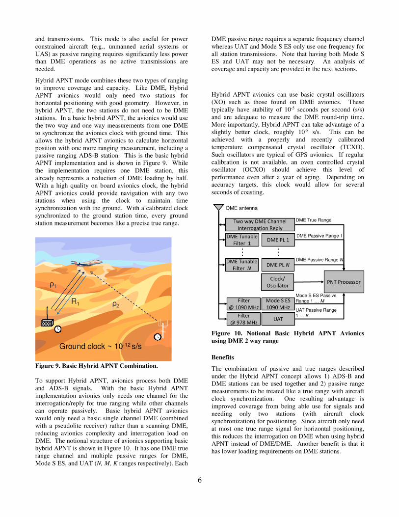
Hybrid APNT mode combines these two types of ranging
to improve coverage and capacity. Like DME, Hybrid
APNT avionics would only need two stations for
horizontal positioning with good geometry. However, in
hybrid APNT, the two stations do not need to be DME
stations. In a basic hybrid APNT, the avionics would use
the two way and one way measurements from one DME
to synchronize the avionics clock with ground time. This
allows the hybrid APNT avionics to calculate horizontal
position with one more ranging measurement, including a
passive ranging ADS-B station. This is the basic hybrid
APNT implementation and is shown in Figure 9. While
the implementation requires one DME station, this
already represents a reduction of DME loading by half.
With a high quality on board avionics clock, the hybrid
APNT avionics could provide navigation with any two
stations when using the clock to maintain time
synchronization with the ground. With a calibrated clock
synchronized to the ground station time, every ground
station measurement becomes like a precise true range.
R1 ρ2
ρ1
Ground clock ~ 10-12 s/s
Figure 9. Basic Hybrid APNT Combination.
To support Hybrid APNT, avionics process both DME
and ADS-B signals. With the basic Hybrid APNT
implementation avionics only needs one channel for the
interrogation/reply for true ranging while other channels
can operate passively. Basic hybrid APNT avionics
would only need a basic single channel DME (combined
with a pseudolite receiver) rather than a scanning DME,
reducing avionics complexity and interrogation load on
DME. The notional structure of avionics supporting basic
hybrid APNT is shown in Figure 10. It has one DME true
range channel and multiple passive ranges for DME,
Mode S ES, and UAT (N, M, K ranges respectively). Each
DME passive range requires a separate frequency channel
whereas UAT and Mode S ES only use one frequency for
all station transmissions. Note that having both Mode S
ES and UAT may not be necessary. An analysis of
coverage and capacity are provided in the next sections.
Hybrid APNT avionics can use basic crystal oscillators
(XO) such as those found on DME avionics. These
typically have stability of 10-5 seconds per second (s/s)
and are adequate to measure the DME round-trip time.
More importantly, Hybrid APNT can take advantage of a
slightly better clock, roughly 10-8 s/s. This can be
achieved with a properly and recently calibrated
temperature compensated crystal oscillator (TCXO).
Such oscillators are typical of GPS avionics. If regular
calibration is not available, an oven controlled crystal
oscillator (OCXO) should achieve this level of
performance even after a year of aging. Depending on
accuracy targets, this clock would allow for several
seconds of coasting.
PNT ProcessorClock/
Oscillator
Mode S ES
1090 MHz
UAT
Two way DME Channel
Interrogation Reply
DME PL 1
Filter
@ 1090 MHz
Filter
@ 978 MHz
DME Tunable
Filter 1
DME True Range
DME Passive Range 1
Mode S ES Passive Range 1 … M
UAT Passive Range
1 … K
DME PL NDME Tunable
Filter N
……
DME Passive Range N
DME antenna
Figure 10. Notional Basic Hybrid APNT Avionics
using DME 2 way range
Benefits
The combination of passive and true ranges described
under the Hybrid APNT concept allows 1) ADS-B and
DME stations can be used together and 2) passive range
measurements to be treated like a true range with aircraft
clock synchronization. One resulting advantage is
improved coverage from being able use for signals and
needing only two stations (with aircraft clock
synchronization) for positioning. Since aircraft only need
at most one true range signal for horizontal positioning,
this reduces the interrogation on DME when using hybrid
APNT instead of DME/DME. Another benefit is that it
has lower loading requirements on DME stations.
7
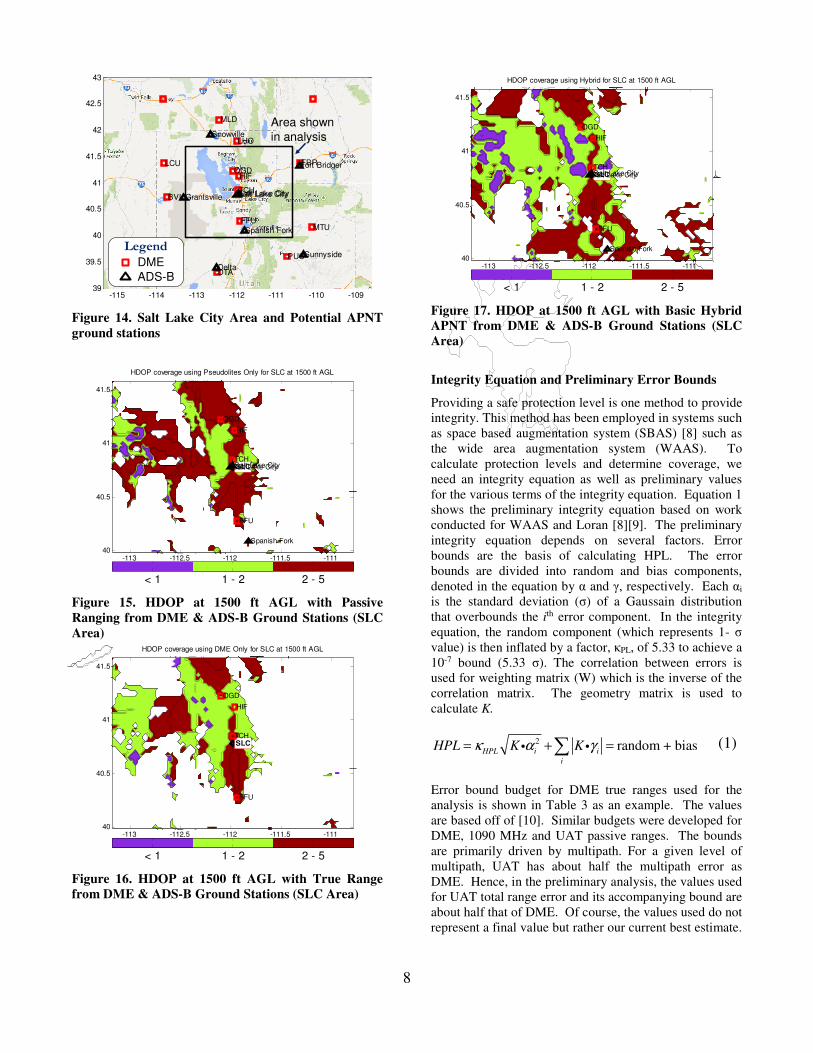
4. PRELIMINARY COVERAGE ANALYSES
One benefit of hybrid APNT is improved coverage. It
will have better coverage than pseudolites only. The
basic hybrid APNT implementation also should generally
have comparable or better coverage than true ranging
from DME or ADS-B ground station. The benefit over
latter occurs because hybrid APNT allows for the
combined use of both DME and ADS-B ground stations.
A basic coverage tool was developed to examine the
benefits of hybrid APNT. For the analysis, two regions
are examined: 1) San Francisco (SF) Bay Area and 2) Salt
Lake (SL) City Area. The coverage tool calculates the
line of sight (LOS) at each examined altitude using a 4/3rd
earth model for radio horizon. The coverage range is
assumed to be about 100 nautical miles (nm). The
horizontal dilution of precision (HDOP) and horizontal
protection level (HPL) coverage is shown in this paper.
The HDOP is used to illustrate the geometry dependence.
As coverage typically driven by integrity, the coverage of
targeted HPL is examined. The calculation of HPL
depends on the bound models for the various components
of range and position error. While these have been
developed for the potential APNT signals, they are
preliminary.
San Francisco represents a region with good DME
coverage with only a few ADS-B ground stations. These
ground stations are located at San Francisco airport
(SFO), Woodside and San Jose. The Woodside ADS-B is
close to an existing DME/TACAN station. There are
several ADS-B ground stations at SFO to support airport
surveillance. Figure 11 to Figure 13 show the HDOP for
pseudolite, DME and basic Hybrid APNT at 500 feet
above ground level (AGL), respectively. DME and ADS-
B stations are labeled as red squares and black triangles,
respectively. pseudolite coverage is the worst. DME and
basic Hybrid APNT HDOP coverage is similar with DME
better in some places and Hybrid better in others.
SF
NUQ
OAK
OSI
PYE
SAU
SFO
SGD
SJC
SUU
San Jose
San Carlos
San FranciscoSan Francisco
HDOP coverage using Pseudolites Only for SF at 500 ft AGL
-123.5 -123 -122.5 -122 -121.5
37
37.2
37.4
37.6
37.8
38
38.2
38.4
< 1 1 - 2 2 - 5
Figure 11. HDOP at 500 ft AGL with Passive Ranging
from DME & ADS-B Ground Stations (SF Area)
SF
NUQ
OAK
OSI
PYE
SAU
SFO
SGD
SJC
SUU
HDOP coverage using DME Only for SF at 500 ft AGL
-123.5 -123 -122.5 -122 -121.5
37
37.2
37.4
37.6
37.8
38
38.2
38.4
< 1 1 - 2 2 - 5
Figure 12. HDOP at 500 ft AGL with True Ranging
from DME Ground Stations (SF Area)
SF
NUQ
OAK
OSI
PYE
SAU
SFO
SGD
SJC
SUU
San Jose
San Carlos
San FranciscoSan Francisco
HDOP coverage using Hybrid for SF at 500 ft AGL
-123.5 -123 -122.5 -122 -121.5
37
37.2
37.4
37.6
37.8
38
38.2
38.4
< 1 1 - 2 2 - 5
Figure 13. HDOP at 500 ft AGL with Basic Hybrid
APNT, DME & ADS-B Ground Stations (SF Area)
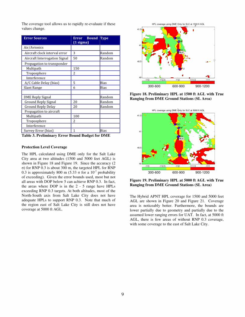
Salt Lake represents a challenging area for APNT due to
the surrounding mountainous terrain. SL is essentially
surrounded by mountains, especially towards the east.
Figure 14 shows the analysis region centered on Salt Lake
City International Airport (SLC) along with the DME,
TACAN and ADS-B stations around the analysis area.
Figure 15 to Figure 17 show the HDOP for PL, DME and
basic Hybrid APNT at 1500 feet AGL. There are a few
ADS-B stations used (one to the west, northwest and
southwest) that are used by outside the region displayed
in the figure. Because of the additional ADS-B ground
stations and their favorable geometry, hybrid shows
significant improvement in coverage than DME.
8
-115 -114 -113 -112 -111 -110 -10939
39.5
40
40.5
41
41.5
42
42.5
43
BVL
DTA
FBR
FFU
HIF
LCU
LHO
MLD
MTU
OGD
PUC
TCH
Sunnyside
Fort Bridger
Grantsville
Spanish Fork
Snowville
Delta
Salt Lake CitySalt Lake City
Legend
DME
ADS-B
Area shown
in analysis
Figure 14. Salt Lake City Area and Potential APNT
ground stations
SLC
FFU
HIF
OGD
TCH
Spanish Fork
Salt Lake CitySalt Lake City
HDOP coverage using Pseudolites Only for SLC at 1500 ft AGL
-113 -112.5 -112 -111.5 -11140
40.5
41
41.5
< 1 1 - 2 2 - 5
Figure 15. HDOP at 1500 ft AGL with Passive
Ranging from DME & ADS-B Ground Stations (SLC
Area)
SLC
FFU
HIF
OGD
TCH
HDOP coverage using DME Only for SLC at 1500 ft AGL
-113 -112.5 -112 -111.5 -11140
40.5
41
41.5
< 1 1 - 2 2 - 5
Figure 16. HDOP at 1500 ft AGL with True Range
from DME & ADS-B Ground Stations (SLC Area)
SLC
FFU
HIF
OGD
TCH
Spanish Fork
Salt Lake CitySalt Lake City
HDOP coverage using Hybrid for SLC at 1500 ft AGL
-113 -112.5 -112 -111.5 -11140
40.5
41
41.5
< 1 1 - 2 2 - 5
Figure 17. HDOP at 1500 ft AGL with Basic Hybrid
APNT from DME & ADS-B Ground Stations (SLC
Area)
Integrity Equation and Preliminary Error Bounds
Providing a safe protection level is one method to provide
integrity. This method has been employed in systems such
as space based augmentation system (SBAS) [8] such as
the wide area augmentation system (WAAS). To
calculate protection levels and determine coverage, we
need an integrity equation as well as preliminary values
for the various terms of the integrity equation. Equation 1
shows the preliminary integrity equation based on work
conducted for WAAS and Loran [8][9]. The preliminary
integrity equation depends on several factors. Error
bounds are the basis of calculating HPL. The error
bounds are divided into random and bias components,
denoted in the equation by α and γ, respectively. Each αi
is the standard deviation (σ) of a Gaussain distribution
that overbounds the ith error component. In the integrity
equation, the random component (which represents 1- σ
value) is then inflated by a factor, κPL, of 5.33 to achieve a
10-7 bound (5.33 σ). The correlation between errors is
used for weighting matrix (W) which is the inverse of the
correlation matrix. The geometry matrix is used to
calculate K.
2 random + bias
HPL i i
i
HPL K Kκ α γ= + =∑i i (1)
Error bound budget for DME true ranges used for the
analysis is shown in Table 3 as an example. The values
are based off of [10]. Similar budgets were developed for
DME, 1090 MHz and UAT passive ranges. The bounds
are primarily driven by multipath. For a given level of
multipath, UAT has about half the multipath error as
DME. Hence, in the preliminary analysis, the values used
for UAT total range error and its accompanying bound are
about half that of DME. Of course, the values used do not
represent a final value but rather our current best estimate.
9
The coverage tool allows us to rapidly re-evaluate if these
values change.
Error Sources Error Bound
(1 sigma) Type
Air/Avionics
Aircraft clock interval error 3 Random
Aircraft Interrogation Signal 50 Random
Propagation to transponder
Multipath 150
Troposphere 2
Interference
A/C Cable Delay (bias) 5 Bias
Slant Range 6 Bias
DME Reply Signal Random
Ground Reply Signal 20 Random
Ground Reply Delay 20 Random
Propagation to aircraft
Multipath 100
Troposphere 2
Interference
Survey Error (bias) 1 Bias
Table 3. Preliminary Error Bound Budget for DME
Protection Level Coverage
The HPL calculated using DME only for the Salt Lake
City area at two altitudes (1500 and 5000 feet AGL) is
shown in Figure 18 and Figure 19. Since the accuracy (2
σ) for RNP 0.3 is about 300 m, the targeted HPL for RNP
0.3 is approximately 800 m (5.33 σ for a 10-7 probability
of exceeding). Given the error bounds used, most but not
all areas with DOP below 5 can achieve RNP 0.3. In fact,
the areas where DOP is in the 2 - 5 range have HPLs
exceeding RNP 0.3 targets. At both altitudes, most of the
North-South axis from Salt Lake City does not have
adequate HPLs to support RNP 0.3. Note that much of
the region east of Salt Lake City is still does not have
coverage at 5000 ft AGL.
SLC
FFU
HIF
OGD
TCH
HPL coverage using DME Only for SLC at 1500 ft AGL
-113 -112.5 -112 -111.5 -11140
40.5
41
41.5
300-600 600-900 900-1200
Figure 18. Preliminary HPL at 1500 ft AGL with True
Ranging from DME Ground Stations (SL Area)
SLC
FFU
HIF
OGD
TCH
HPL coverage using DME Only for SLC at 5000 ft AGL
-113 -112.5 -112 -111.5 -11140
40.5
41
41.5
300-600 600-900 900-1200
Figure 19. Preliminary HPL at 5000 ft AGL with True
Ranging from DME Ground Stations (SL Area)
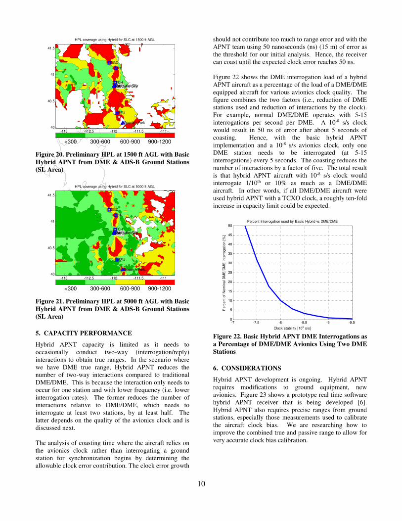
The Hybrid APNT HPL coverage for 1500 and 5000 feet
AGL are shown in Figure 20 and Figure 21. Coverage
area is noticeably better. Furthermore, the bounds are
lower partially due to geometry and partially due to the
assumed lower ranging errors for UAT. In fact, at 5000 ft
AGL, there is few areas of without RNP 0.3 coverage,
with some coverage to the east of Salt Lake City.
10
SLC
FFU
HIF
OGD
TCH
Spanish Fork
Salt Lake CitySalt Lake City
HPL coverage using Hybrid for SLC at 1500 ft AGL
-113 -112.5 -112 -111.5 -11140
40.5
41
41.5
<300 300-600 600-900 900-1200
Figure 20. Preliminary HPL at 1500 ft AGL with Basic
Hybrid APNT from DME & ADS-B Ground Stations
(SL Area)
SLC
FFU
HIF
OGD
TCH
Spanish Fork
Salt Lake CitySalt Lake City
HPL coverage using Hybrid for SLC at 5000 ft AGL
-113 -112.5 -112 -111.5 -11140
40.5
41
41.5
<300 300-600 600-900 900-1200
Figure 21. Preliminary HPL at 5000 ft AGL with Basic
Hybrid APNT from DME & ADS-B Ground Stations
(SL Area)
5. CAPACITY PERFORMANCE
Hybrid APNT capacity is limited as it needs to
occasionally conduct two-way (interrogation/reply)
interactions to obtain true ranges. In the scenario where
we have DME true range, Hybrid APNT reduces the
number of two-way interactions compared to traditional
DME/DME. This is because the interaction only needs to
occur for one station and with lower frequency (i.e. lower
interrogation rates). The former reduces the number of
interactions relative to DME/DME, which needs to
interrogate at least two stations, by at least half. The
latter depends on the quality of the avionics clock and is
discussed next.
The analysis of coasting time where the aircraft relies on
the avionics clock rather than interrogating a ground
station for synchronization begins by determining the
allowable clock error contribution. The clock error growth
should not contribute too much to range error and with the
APNT team using 50 nanoseconds (ns) (15 m) of error as
the threshold for our initial analysis. Hence, the receiver
can coast until the expected clock error reaches 50 ns.
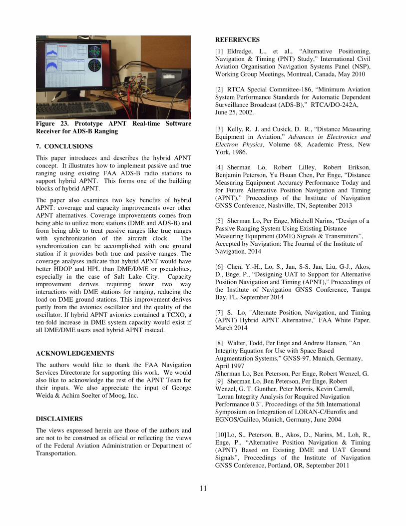
Figure 22 shows the DME interrogation load of a hybrid
APNT aircraft as a percentage of the load of a DME/DME
equipped aircraft for various avionics clock quality. The
figure combines the two factors (i.e., reduction of DME
stations used and reduction of interactions by the clock).
For example, normal DME/DME operates with 5-15
interrogations per second per DME. A 10-8 s/s clock
would result in 50 ns of error after about 5 seconds of
coasting. Hence, with the basic hybrid APNT
implementation and a 10-8 s/s avionics clock, only one
DME station needs to be interrogated (at 5-15
interrogations) every 5 seconds. The coasting reduces the
number of interactions by a factor of five. The total result
is that hybrid APNT aircraft with 10-8 s/s clock would
interrogate 1/10th or 10% as much as a DME/DME
aircraft. In other words, if all DME/DME aircraft were
used hybrid APNT with a TCXO clock, a roughly ten-fold
increase in capacity limit could be expected.
-9.5-9-8.5-8-7.5-70
5
10
15
20
25
30
35
40
45
50P
erc
ent
of
Nom
inal D
ME
/DM
E inte
rrogation [
%]
Clock stability [10x s/s]
Percent Interrogation used by Basic Hybrid vs DME/DME
Figure 22. Basic Hybrid APNT DME Interrogations as
a Percentage of DME/DME Avionics Using Two DME
Stations
6. CONSIDERATIONS
Hybrid APNT development is ongoing. Hybrid APNT
requires modifications to ground equipment, new
avionics. Figure 23 shows a prototype real time software
hybrid APNT receiver that is being developed [6].
Hybrid APNT also requires precise ranges from ground
stations, especially those measurements used to calibrate
the aircraft clock bias. We are researching how to
improve the combined true and passive range to allow for
very accurate clock bias calibration.
11
Figure 23. Prototype APNT Real-time Software
Receiver for ADS-B Ranging
7. CONCLUSIONS
This paper introduces and describes the hybrid APNT
concept. It illustrates how to implement passive and true
ranging using existing FAA ADS-B radio stations to
support hybrid APNT. This forms one of the building
blocks of hybrid APNT.
The paper also examines two key benefits of hybrid
APNT: coverage and capacity improvements over other
APNT alternatives. Coverage improvements comes from
being able to utilize more stations (DME and ADS-B) and
from being able to treat passive ranges like true ranges
with synchronization of the aircraft clock. The
synchronization can be accomplished with one ground
station if it provides both true and passive ranges. The
coverage analyses indicate that hybrid APNT would have
better HDOP and HPL than DME/DME or pseudolites,
especially in the case of Salt Lake City. Capacity
improvement derives requiring fewer two way
interactions with DME stations for ranging, reducing the
load on DME ground stations. This improvement derives
partly from the avionics oscillator and the quality of the
oscillator. If hybrid APNT avionics contained a TCXO, a
ten-fold increase in DME system capacity would exist if
all DME/DME users used hybrid APNT instead.
ACKNOWLEDGEMENTS
The authors would like to thank the FAA Navigation
Services Directorate for supporting this work. We would
also like to acknowledge the rest of the APNT Team for
their inputs. We also appreciate the input of George
Weida & Achim Soelter of Moog, Inc.
DISCLAIMERS
The views expressed herein are those of the authors and
are not to be construed as official or reflecting the views
of the Federal Aviation Administration or Department of
Transportation.
REFERENCES
[1] Eldredge, L., et al., “Alternative Positioning,
Navigation & Timing (PNT) Study,” International Civil
Aviation Organisation Navigation Systems Panel (NSP),
Working Group Meetings, Montreal, Canada, May 2010
[2] RTCA Special Committee-186, “Minimum Aviation
System Performance Standards for Automatic Dependent
Surveillance Broadcast (ADS-B),” RTCA/DO-242A,
June 25, 2002.
[3] Kelly, R. J. and Cusick, D. R., “Distance Measuring
Equipment in Aviation,” Advances in Electronics and
Electron Physics, Volume 68, Academic Press, New
York, 1986.
[4] Sherman Lo, Robert Lilley, Robert Erikson,
Benjamin Peterson, Yu Hsuan Chen, Per Enge, “Distance
Measuring Equipment Accuracy Performance Today and
for Future Alternative Position Navigation and Timing
(APNT),” Proceedings of the Institute of Navigation
GNSS Conference, Nashville, TN, September 2013
[5] Sherman Lo, Per Enge, Mitchell Narins, “Design of a
Passive Ranging System Using Existing Distance
Measuring Equipment (DME) Signals & Transmitters”,
Accepted by Navigation: The Journal of the Institute of
Navigation, 2014
[6] Chen, Y.-H., Lo, S., Jan, S-S. Jan, Liu, G-J., Akos,
D., Enge, P., “Designing UAT to Support for Alternative
Position Navigation and Timing (APNT),” Proceedings of
the Institute of Navigation GNSS Conference, Tampa
Bay, FL, September 2014
[7] S. Lo, "Alternate Position, Navigation, and Timing
(APNT) Hybrid APNT Alternative," FAA White Paper,
March 2014
[8] Walter, Todd, Per Enge and Andrew Hansen, “An
Integrity Equation for Use with Space Based
Augmentation Systems,” GNSS-97, Munich, Germany,
April 1997
/Sherman Lo, Ben Peterson, Per Enge, Robert Wenzel, G.
[9] Sherman Lo, Ben Peterson, Per Enge, Robert
Wenzel, G. T. Gunther, Peter Morris, Kevin Carroll,
"Loran Integrity Analysis for Required Navigation
Performance 0.3", Proceedings of the 5th International
Symposium on Integration of LORAN-C/Eurofix and
EGNOS/Galileo, Munich, Germany, June 2004
[10] Lo, S., Peterson, B., Akos, D., Narins, M., Loh, R.,
Enge, P., “Alternative Position Navigation & Timing
(APNT) Based on Existing DME and UAT Ground
Signals”, Proceedings of the Institute of Navigation
GNSS Conference, Portland, OR, September 2011
Top Related