


Languages
Pages
Legal


HP Array Configuration Utility User Guide
Oracle Solaris 10 for x86/x64 Systems
Sixth edition April 2010

Legal notices
© Copyright 2007-10 Hewlett-Packard Development Company, L.P.
Confidential computer software. Valid license from HP required for possession, use or copying. Consistent with FAR 12.211 and12.212, Commercial Computer Software, Computer Software Documentation, and Technical Data for Commercial Items arelicensed to the U.S. Government under vendor's standard commercial license.
The information contained herein is subject to change without notice. The only warranties for HP products and services are setforth in the express warranty statements accompanying such products and services. Nothing herein should be construed asconstituting an additional warranty. HP shall not be liable for technical or editorial errors or omissions contained herein.
Microsoft and Windows are U.S. registered trademarks of Microsoft Corporation. Intel is a trademark of Intel Corporation in theU.S. and other countries. Java™ is a U.S. trademark of Sun Microsystems, Inc. AMD is a trademark of Advanced Micro Devices,Inc.

Contents 3
Contents
Getting Started ....................................................................................................................................5
Features .....................................................................................................................................................5
Advanced Features .....................................................................................................................................5
System requirements....................................................................................................................................6
Hardware Requirements .........................................................................................................................6
Software Requirements ...........................................................................................................................6
Package Installation and Configuration ...................................................................................................7
Unpacking the Distribution ...........................................................................................................................7
Installing the Array Configuration Utility ........................................................................................................7
Installing into a GRUB-based Miniroot ...........................................................................................................8
Package maintenance...........................................................................................................................9
Package Removal .......................................................................................................................................9
Package Upgrade.......................................................................................................................................9
Using the Command Line Interface........................................................................................................10
Overview of the ACU CLI...........................................................................................................................10
Running the CLI....................................................................................................................................10
CLI syntax ...........................................................................................................................................10
Keyword abbreviations.........................................................................................................................11
Hiding warning prompts .......................................................................................................................12
Querying a device ...............................................................................................................................12
Help ...................................................................................................................................................12
Typical procedures....................................................................................................................................13
Creating a logical drive........................................................................................................................13
Modifying the controller chassis name....................................................................................................15
Deleting target devices .........................................................................................................................15
Identifying devices ...............................................................................................................................15
Expanding an array .............................................................................................................................16
Extending a logical drive ......................................................................................................................16
Managing spare drives ........................................................................................................................17
Migrating a logical drive ......................................................................................................................17
Changing the Rebuild Priority setting......................................................................................................18
Changing the Expand Priority setting .....................................................................................................18
Changing the controller cache ratio .......................................................................................................18
Changing the surface scan delay time....................................................................................................19
Re-enabling a failed logical drive ..........................................................................................................19
Enabling or disabling the drive cache ....................................................................................................19
Enabling or disabling the array accelerator ............................................................................................19
Setting the target..................................................................................................................................20
Rescanning the system..........................................................................................................................21
Generating a diagnostic report .............................................................................................................21
Erasing a physical or logical drive.........................................................................................................21
Entering or deleting a license key ..........................................................................................................22
Secure Erase .......................................................................................................................................23
Advanced Capacity Expansion .............................................................................................................24
RAID 60 (fault tolerance) ......................................................................................................................24
Probability of logical drive failure.........................................................................................................25

Contents 4
Factors involved in logical drive failure .......................................................................................................25
Drive arrays and fault-tolerance methods ...............................................................................................26
Drive arrays .............................................................................................................................................26
Fault-tolerance methods .............................................................................................................................28
Hardware-based fault-tolerance methods ................................................................................................29
Comparing the hardware-based RAID methods .......................................................................................35
Selecting a RAID method ......................................................................................................................35
Alternative fault-tolerance methods..............................................................................................................36
Diagnosing array problems .................................................................................................................37
Diagnostic tools ........................................................................................................................................37
ADU...................................................................................................................................................37
POST messages ...................................................................................................................................37
Server Diagnostics ...............................................................................................................................37
Glossary ...........................................................................................................................................38

Getting Started 5
Getting Started
FeaturesThe HP Array Configuration Utility (ACU) is a command line interface utility that can be used online (while
the operating system is resident). The utility has different operating modes, enabling faster configuration
or greater control over the configuration option, depending on the task. ACU also enables several array
features:
Online array capacity expansion
Logical drive capacity extension
Assignment of online spares
RAID or stripe size migration
Advanced FeaturesSome ACU features are available only for later versions of ACU, Smart Array firmware, and Smart Array
drivers. For HPQaculi 2.0.0 with firmware revision 5.10 and CPQary3 1.90 or later, the following
features are available:
Dual Domain/Port—Smart Array P800
108 HDD Maximum—Smart Array E500, P400, P400i, P800
64 LUN Support—Smart Array E500, P400, P400i, P800
Dual Path SATA—Smart Array P800
Hot Replacing Expanders—Smart Array P800
HPQacucli-3.0.1 and CPQary3 2.2.0 or later adds support for a new series of firmware for Smart Array
SAS controllers:
SAP410i
SAP410
SAP212
SAP712m
SAP410i, SAP410, SAP212, SAP712m and SAP411 controllers add support for the following features.
Secure Erase
Advanced Capacity Expansion
RAID Support of RAID 50 and RAID 60
Surface Analysis Configurability
HPQacucli-3.1.0 and CPQary3 2.2.0 or later adds support for a new series of firmware for Smart Array
SAS Controllers:
SAP411
HPQacucli-3.1.0 and above adds support for these new features:
ACUCLI now retains a command history of previously executed commands, which can be accessedby using the keyboard arrow keys.
ACUCLI allows command completion by pressing ‘Tab’ key

Getting Started 6
Generate diagnostic information about a specified or all controllers on the system
System requirements
Hardware RequirementsAn HP ProLiant server for which the HPQacucli package is supported. A list of supported ProLiant models is
provided in the RELEASE NOTES provided in the HPQacucli package or online at http://www.hp.com/go/solaris.
Software RequirementsThe HPQacucli package has very few software requirements, as follows:
Oracle Solaris 10 8/07 or later
HP Smart Array Controller Driver version 2.40 or later

Package Installation and Configuration 7
Package Installation and Configuration
Unpacking the DistributionThe Array Configuration Utility is distributed as a gzip-compressed tar file which must be unpacked before
use. The instructions below can be used on Solaris and other similar operating systems for which the
tar(1) or gunzip(1) tools are available.
1. Download the HPQacucli distribution compressed tar file to a temporary local directory, such as
/var/tmp. The name of the tar file has the form HPQacucli-x.y.z-
solaris10.i386.tar.gz.
2. Uncompress and un-tar the compressed tar file to extract the HPQacucli package:
$ cd /var/tmp
$ gunzip HPQacucli-x.y.z-solaris10-i386.tar.gz
$ tar xvf HPQacucli-x.y.z-solaris10- i386.tar
$ cd HPQacucli-x.y.z-solaris10-i386
$ more LICENSE.HPQacucli
$ more RELEASENOTES.HPQacucli
The distribution contains the following components:
LICENSE.HPQacucli — Text file containing the end-user license which governs use of the distribution and its contents.
RELEASENOTES.HPQacucli — Text file containing the release notes for the distribution.
INSTALLNOTES.HPQacucli — Text file containing the installation notes for the distribution.
HPQacucli-x.y.z-solaris10-i386.pkg — Solaris package for the ACUCLI utility
LICENSE.libstdc++ — GNU General Public License
NOTE: You must agree to the terms of the license in order to install and use the HPQacucli packageand its components.
Installing the Array Configuration UtilityUse the following procedure to install the Array Configuration utility on to an existing Solaris 10 system. If
necessary, unpack the distribution as described above under “Unpacking the Distribution”.
Log in as root and use pkgadd (1M) to install the HPQacucli package.
$ pwd
/var/tmp/HPQacucli-x.y.z-solaris10-i386
$ su
# pkgadd -d HPQacucli-<x.y.z>-solaris10-i386.pkg
Installation of <HPQacucli> was successful.
A message similar to the above is displayed following a successful installation.
Package Installation and Configuration 8
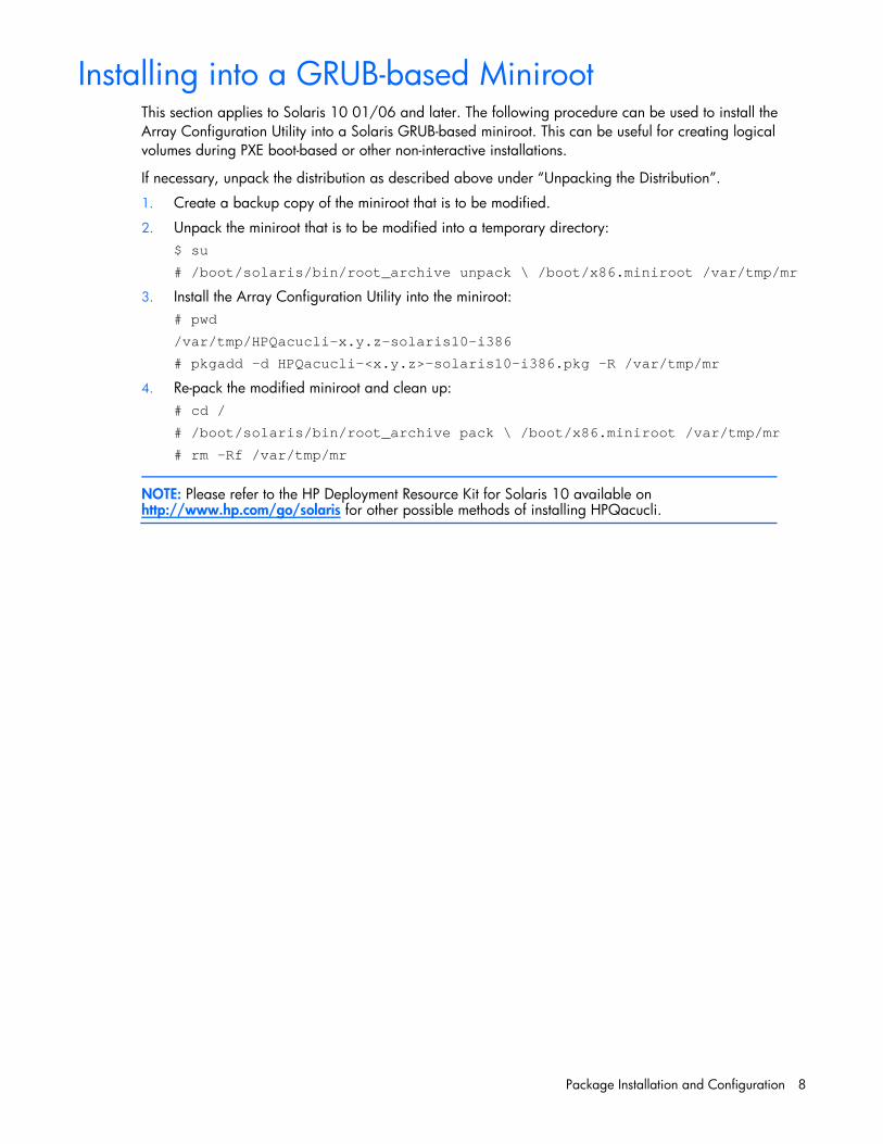
Installing into a GRUB-based MinirootThis section applies to Solaris 10 01/06 and later. The following procedure can be used to install the
Array Configuration Utility into a Solaris GRUB-based miniroot. This can be useful for creating logical
volumes during PXE boot-based or other non-interactive installations.
If necessary, unpack the distribution as described above under “Unpacking the Distribution”.
1. Create a backup copy of the miniroot that is to be modified.
2. Unpack the miniroot that is to be modified into a temporary directory:
$ su
# /boot/solaris/bin/root_archive unpack \ /boot/x86.miniroot /var/tmp/mr
3. Install the Array Configuration Utility into the miniroot:
# pwd
/var/tmp/HPQacucli-x.y.z-solaris10-i386
# pkgadd -d HPQacucli-<x.y.z>-solaris10-i386.pkg -R /var/tmp/mr
4. Re-pack the modified miniroot and clean up:
# cd /
# /boot/solaris/bin/root_archive pack \ /boot/x86.miniroot /var/tmp/mr
# rm -Rf /var/tmp/mr
NOTE: Please refer to the HP Deployment Resource Kit for Solaris 10 available onhttp://www.hp.com/go/solaris for other possible methods of installing HPQacucli.

Package maintenance 9
Package maintenance
Package RemovalTo remove the HPQacucli package, use pkgrm(1M):
$ su
# pkgrm HPQacucli
pkgrm will stop the acucli utility, if necessary, and remove the package and its components from the
system.
IMPORANT: pkgrm should be run on the server from which the package is being removed. It isrecommended that the -R option to pkgrm not be used because, in addition to removing files,package removal must also unconfigure the smf(5) service, which cannot be done if pkgrm isoperating on an alternate root.
Package UpgradeTo upgrade the HPQacucli package, first remove the existing version of the package, and then add the
desired version of the package:
1. Remove the current package:
$ su
# pkgrm HPQacucli
2. Add the new package, following the steps outlined above in “Package Installation”.
IMPORANT: Replacing the HPQacucli package without first removing the previously installedHPQacucli package is not recommended and may result in undefined behavior.
Using the Command Line Interface 10
Using the Command Line Interface
Overview of the ACU CLIThe HP Array Configuration Utility is a command line utility that can be used online to create new logical
volumes, delete logical volumes, enable online array capacity expansion, extend logical drive capacity,
assign online spares, migrate RAID configurations or stripe size, perform a Secure Erase, or make use of
advanced capacity expansion. In addition, the HP Array Configuration Utility can be used for getting
information about HP Smart Array controllers and the devices connected to the controller.
Running the CLIYou can open the CLI in either Console mode or Command mode. In Console mode, you can adjust
several configuration parameters on several devices without having to restart ACU each time. Command
mode is more suitable for an isolated change of just one configuration parameter on one device.
The command syntax used to open the ACU CLI depends on the desired mode of operation:
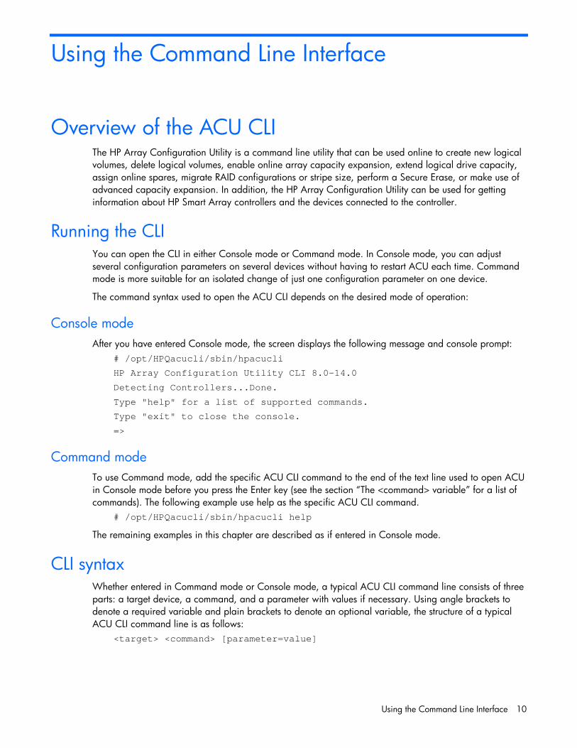
Console mode
After you have entered Console mode, the screen displays the following message and console prompt:
# /opt/HPQacucli/sbin/hpacucli
HP Array Configuration Utility CLI 8.0-14.0
Detecting Controllers...Done.
Type "help" for a list of supported commands.
Type "exit" to close the console.
=>
Command mode
To use Command mode, add the specific ACU CLI command to the end of the text line used to open ACU
in Console mode before you press the Enter key (see the section “The <command> variable” for a list of
commands). The following example use help as the specific ACU CLI command.
# /opt/HPQacucli/sbin/hpacucli help
The remaining examples in this chapter are described as if entered in Console mode.
CLI syntaxWhether entered in Command mode or Console mode, a typical ACU CLI command line consists of three
parts: a target device, a command, and a parameter with values if necessary. Using angle brackets to
denote a required variable and plain brackets to denote an optional variable, the structure of a typical
ACU CLI command line is as follows:
<target> <command> [parameter=value]
Using the Command Line Interface 11
The <target> variable
This variable provides the path to a target device. The device can be a controller, an array, a logical
drive, or a physical drive. For example:
controller slot=3
controller csn=E03TMLJ135
controller serialnumber=P56350D9IP903J
controller slot=3 array A
controller chassisname="A" array A logicaldrive 2
controller chassisname="A" physicaldrive 1:0
You can also specify that an operation be performed on several similar devices at the same time. For
example:
controller all
controller slot=3 logicaldrive 2
The <command> variable
The <command> variable can be any of the following words or phrases:
add
create
delete
help
modify
remove
rescan
set
target
diag
Some commands require a parameter, and some parameters require a value. The descriptions of the
commands in the rest of this chapter provide examples of some usable parameters and variables for those
cases that need them.
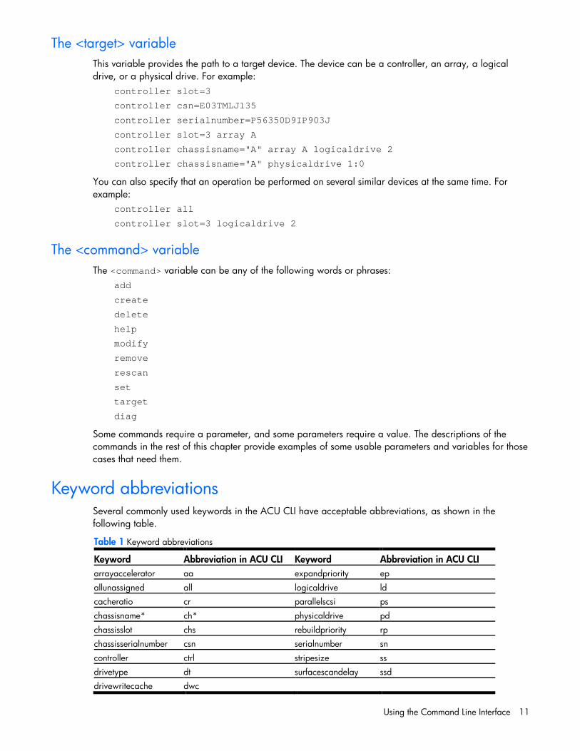
Keyword abbreviationsSeveral commonly used keywords in the ACU CLI have acceptable abbreviations, as shown in the
following table.
Table 1 Keyword abbreviations
Keyword Abbreviation in ACU CLI Keyword Abbreviation in ACU CLI
arrayaccelerator aa expandpriority ep
allunassigned all logicaldrive ld
cacheratio cr parallelscsi ps
chassisname* ch* physicaldrive pd
chassisslot chs rebuildpriority rp
chassisserialnumber csn serialnumber sn
controller ctrl stripesize ss
drivetype dt surfacescandelay ssd
drivewritecache dwc

Using the Command Line Interface 12
*The CLI also uses this keyword and abbreviation for the terms box name and RAID array ID.
Hiding warning promptsWhen entering a command for an operation that can potentially destroy user data, the CLI displays a
warning and prompts for input (a y or n) before continuing the operation. This situation is undesirable
when running batch file scripts. To prevent warning prompts from being displayed, use the term forced as
a parameter.
Example command:
ctrl ch="Lab4" ld 1 delete forced
Querying a deviceIf you do not know what values a parameter can have, you can sometimes query the device to find
available parameters by entering a ? as the value of the parameter.
Example command:
=> ctrl ch="Lab4" ld 1 modify raid=0 ss=?
A typical screen response in this case could be:
Available options are:
8
16 (current value)
32
64
128 (default)
256
For information about which parameters can be queried, refer to the CLI help (“Help”).
HelpTo get help with the CLI, enter help at the CLI prompt as follows:
=> help
This command does not need a target variable or a parameter.
Using the Command Line Interface 13
Typical proceduresThe following sections describe some common ACU CLI procedures.
Creating a logical driveWhen you use the CLI to create a logical drive, the array that holds the logical drive is created implicitly.
Syntax:
<target> create type=ld [parameter=value]
To create a logical drive on a new array, specify both the controller and the drives that are to constitute
the new array. You can specify each drive individually, or you can specify a drive range. For example:
ctrl slot=5 create type=ld drives=1:0,1:1,1:3 raid=adg
ctrl slot=5 create type=ld drives=1:1-1:3 raid=adg
To create a logical drive on an existing array, specify the array. You do not need to specify the drives in
this case because they are already defined. For example:
ctrl slot=5 array A create type=ld size=330 raid=adg
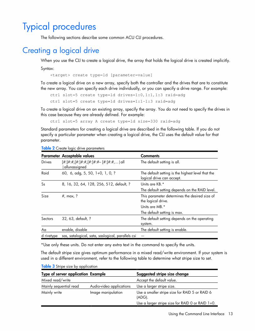
Standard parameters for creating a logical drive are described in the following table. If you do not
specify a particular parameter when creating a logical drive, the CLI uses the default value for that
parameter.
Table 2 Create logic drive parameters
Parameter Acceptable values Comments
Drives [#:]#:#,[#:]#:#,[#:]#:#– [#:]#:#,...|all
|allunassigned
The default setting is all.
Raid 60, 6, adg, 5, 50, 1+0, 1, 0, ? The default setting is the highest level that the
logical drive can accept.
Ss 8, 16, 32, 64, 128, 256, 512, default, ? Units are KB.*
The default setting depends on the RAID level.
Size #, max, ? This parameter determines the desired size of
the logical drive.
Units are MB.*
The default setting is max.
Sectors 32, 63, default, ? The default setting depends on the operating
system.
Aa enable, disable The default setting is enable.
d rivetype sas, satalogical, sata, saslogical, parallels csi —
*Use only these units. Do not enter any extra text in the command to specify the units.
The default stripe size gives optimum performance in a mixed read/write environment. If your system is
used in a different environment, refer to the following table to determine what stripe size to set.
Table 3 Stripe size by application
Type of server application Example Suggested stripe size change
Mixed read/write Accept the default value.
Mainly sequential read Audio-video applications Use a larger stripe size.
Mainly write Image manipulation Use a smaller stripe size for RAID 5 or RAID 6
(ADG).
Use a larger stripe size for RAID 0 or RAID 1+0.

Using the Command Line Interface 14
*Not all controllers support RAID 6 (ADG).
Sample scenario
Consider a situation in which you want to create two arrays in MSA20 storage enclosure. One of these
arrays needs two logical drives, while the other needs only one.
First, determine what physical drives are available and what their properties are:
=> ctrl ch="Lab 4" pd all show
For this sample scenario, the screen response is:
MSA20 in Lab OK)
unassigned physicaldrive OK)
physicaldrive physicaldrive OK)
Knowing this information, you can now create the first array with one logical drive:
=> ctrl ch="Lab 4" create type=ld drives=1:4
Now, verify that the array has been created:
=> ctrl ch="Lab 4" pd all show
In this case, the screen response is:
MSA20 in Lab 4 array A
physicaldrive 1:4 (box 1:bay4, SATA, 250GB, OK)
unassigned
physicaldrive 1:7 (box 1:bay7, SATA, 250GB, OK)
physicaldrive 1:8 (box 1:bay8, SATA, 250GB, OK)
The second array is to be created on the two remaining physical drives. Before creating this array,
determine what RAID options are available for these drives:
=> ctrl ch="Lab 4" create type=ld drives=1:7,1:8 size=300 raid=?
The response in this case is:
Available options are: 0 1+0 (default value)
Now create the new array:
=> ctrl ch="Lab 4" create type=ld drives=1:7,1:8 size=300 raid=1+0
It is not strictly necessary to specify the RAID level in this example because it is the highest possible level
for this scenario and will be used by default. However, it is included in the command as an example.
Now verify that the array has been formed:
=> ctrl ch="Lab 4" pd all show
The screen response is:
MSA20 in Lab 4 array A
physicaldrive 1:4 (box 1:bay4, SATA, 250GB, OK)
array B
physicaldrive 1:7 (box 1:bay7, SATA, 250GB, OK)
physicaldrive 1:8 (box 1:bay8, SATA, 250GB, OK)
Create the second logical drive on this array. There are two possible ways for creating subsequent logical
drives. You can create logical drives by specifying the implicitly created array name shown in the first
example. You can also use the physical drives in the array to distinguish which array to create the logical
drives shown in the second example.
Example:

Using the Command Line Interface 15
=> ctrl ch="Lab 4" array B create type=ld size=900
=> ctrl ch="Lab 4" create type=ld drives=1:7,1:8 size=333
Finally, verify that the logical drives have all been created correctly:
=> ctrl ch="Lab 4" ld all show
MSA20 in Lab 4 array A
logicaldrive 1 (232.9 GB, RAID 0, OK)
array B
logicaldrive 2 (298 MB, RAID 1+0, OK)
logicaldrive 3 (900 MB, RAID 1+0, OK)
logicaldrive 4 (330 MB, RAID 1+0, OK)
Modifying the controller chassis nameIf a controller is configured with at least one logical drive, you can assign the controller a simplified name
(the chassis name) to make it easier to identify and enter the correct controller in a command.
Syntax:
<target> modify ch="new chassis name"
where <target> is a controller. Example commands:
=> ctrl sn=P56350D9IP903J modify ch="Lab 6"
=> ctrl ch="Lab 4" modify ch="Lab 6"
Deleting target devicesSyntax:
<target> delete [forced]
where <target> can be a controller, array, or logical drive. Except in the case of controllers, you can
delete several devices simultaneously if they are of similar type by using the all keyword.
Because deleting a target device can result in data loss, the screen displays a warning prompt unless you
include the forced parameter.
Example commands:
=> ctrl ch="Lab 4" delete forced
=> ctrl slot=3 ld all delete
Identifying devicesYou can enter a command that causes the LEDs on target devices to blink, enabling you to identify the
devices. The LEDs continue to blink until you enter the command to stop them blinking.
Syntax:
<target> modify led=on|off
Example commands:
=> ctrl ch="Lab 4" modify led=on
=> ctrl ch="Lab 4" modify array A led=off

Using the Command Line Interface 16
Expanding an arrayYou can increase the storage space on an array by adding physical drives. However, the added drives
must be of the same type (for example, parallel SCSI or SATA), and they must each have a capacity no
less than that of the existing drives in the array.
NOTE: An array expansion, logical drive extension, or logical drive migration takes about 15
minutes per gigabyte, or considerably longer time if the controller has battery-backed cache. While
this process is occurring, no other expansion, extension, or migration can occur simultaneously on
the same controller.
An array expansion, logical drive extension, or logical drive migration is not supported if the controller
does not have a battery-backed cache.
Syntax:
<target> add drives=[#:]#:#,[#:]#:#,[#: #:#- [#:]#:#,...|allunassigned[forced]
where <target> is an array (or a logical drive, if the array contains only one logical drive). The
parameter forced represses warning message prompts.
If you add an odd number of drives to an array that contains at least one RAID 1+0 logical drive, the CLI
displays a prompt that asks if it is acceptable to convert the RAID1+0 logical drive to RAID 5 (or RAID 6
(ADG) if the controller supports this RAID level). Adding the forced parameter to the command prevents
this prompt from appearing.
Example commands:
=> ctrl slot=3 array A add drives=1:0,1:1
=> ctrl slot=4 ld 1 add drives=allunassigned
=> ctrl slot=5 array A add drives=1:1,1:5
Extending a logical driveIf the operating system supports logical drive extension, you can use any unassigned capacity on an
array to enlarge one or more of the logical drives on the array.
NOTE: An array expansion, logical drive extension, or logical drive migration takes about 15
minutes per gigabyte, or considerably longer time if the controller has battery-backed cache. While
this process is occurring, no other expansion, extension, or migration can occur simultaneously on
the same controller.
An array expansion, logical drive extension, or logical drive migration is not supported if the controller
does not have a battery-backed cache.
Syntax:
<target> modify size=#|max|? [forced]
where <target> is a logical drive.
If the operating system does not support logical drive extension, carrying out this command would make
data on the logical drive unavailable. Therefore, the CLI displays a warning prompt as a safeguard in
case you are using such an operating system. To prevent the prompt from appearing, use the forced
parameter.
Example commands:
=> ctrl slot=3 ld 1 modify size=max

Using the Command Line Interface 17
=> ctrl slot=4 ld 1 modify size=?
=> ctrl slot=3 ld 2 modify size=500 forced
Managing spare drivesAssigning online spares to an array enables you to postpone replacement of faulty drives. However, it
does not increase the fault-tolerance level of any logical drives in the array. For example, a logical drive
in a RAID 5 configuration suffers irretrievable data loss if two physical drives fail, regardless of the
number of spare drives assigned to it.
Syntax:
<target> add spares=[#:]#:#,[#:]#:#,[#:]#:#- [#:] #:#,...|allunassigned[forced]
<target> remove spares=[#:]#:#,[#:]#:#,[#:]#:#- [#:]#:#,...|all
where <target> is an array. If the array contains only one logical drive, the logical drive can also be
the target. The parameter forced represses warning message prompts.
Example commands:
=> ctrl slot=3 array B add spares=1:6
=> ctrl slot=4 arrayall add spares=1:5,1:7
=> ctrl slot=5 array A add spares=1:1,1:5
=> ctrl slot=5 arrayA remove spares=1:1,1:5
Migrating a logical driveThis command enables you to adjust the stripe size (data block size) or RAID level of a selected logical
drive. For information about selecting an appropriate stripe size or RAID level, refer to the tables in the
"Creating a logical drive" and "Selecting a RAID method" sections.
Consider the following factors before performing a migration:
For some RAID-level migrations to be possible, you might need to add one or more drives to the array.
For migration to a larger stripe size to be possible, the array might need to contain unused drive space.
This extra space is necessary because some of the larger data stripes in the migrated array are likely to
be inefficiently filled.
NOTE: An array expansion, logical drive extension, or logical drive migration takes about 15
minutes per gigabyte, or considerably longer time if the controller has battery-backed cache. While
this process is occurring, no other expansion, extension, or migration can occur simultaneously on
the same controller.
An array expansion, logical drive extension, or logical drive migration is not supported if the controller
does not have a battery-backed cache.
Syntax:
<target> modify [raid=0|1+0|1|5|6|adg|?] [ss=8 |16|32|64|128|256|default|?]
where <target> is a logical drive.
The following limitations apply to this command:
You cannot simultaneously query the RAID level and the stripe size of any given logical drive.
If you do not specify a RAID level for a query or migration, the CLI uses the existing value by default.

Using the Command Line Interface 18
If you do not specify a stripe size, the CLI uses the default stripe size value for the RAID level that youspecify.
Example commands:
=> ctrl slot=3 ld 1 modify raid=1 => ctrl slot=4 ld 2 modify ss=16
=> ctrl slot=2 ld 3 modify raid=5 ss=16
Changing the Rebuild Priority settingThe Rebuild Priority setting determines the urgency with which the controller treats an internal command to
rebuild a failed logical drive.
At the low setting, normal system operations take priority over a rebuild.
At the medium setting, rebuilding occurs for half of the time, and normal system operations occur forthe rest of the time.
At the high setting, the rebuild takes precedence over all other system operations.
If the logical drive is part of an array that has an online spare, rebuilding begins automatically when
drive failure occurs. If the array does not have an online spare, rebuilding begins when the failed
physical drive is replaced.
<target> modify rp=high | medium | low
where <target> is a Controller.
Example command:
=> ctrl slot=3 modify rp=high
Changing the Expand Priority settingThe Expand Priority setting determines the urgency with which the controller treats an internal command to
expand an array.
At the low setting level, normal system operations take priority over an array expansion.
At the medium setting, expansion occurs for half of the time, and normal system operations occur forthe rest of the time.
At the high setting, the expansion takes precedence over all other system operations.
Syntax:
<target> modify ep=high | medium | low
where <target> is a controller.
Example command:
=> ctrl slot=3 modify ep=high
Changing the controller cache ratioThe controller cache ratio setting determines the amount of memory allocated to read and write
operations. Different types of applications have different optimum settings. You can change the ratio only
if the controller has a battery-backed cache (because only battery-backed cache can be used for write
cache) and if there are logical drives configured on the controller.
Syntax:
<target> modify cr=#/#|?
where <target> is a controller, and #/# is the cache ratio in the format read percentage/write
percentage.

Using the Command Line Interface 19
Example command:
=> ctrl slot=3 modify cr=25/75
Changing the surface scan delay timeThe setting for the surface scan delay determines the time interval for which a controller must be inactive
before a surface scan analysis is started on the physical drives that are connected to it.
Surface scan analysis is an automatic background process that ensures that you can recover data if a
drive failure occurs. The scanning process checks physical drives in fault-tolerant logical drives for bad
sectors, and in RAID 5 or RAID 6 (ADG) configurations, it also verifies the consistency of parity data.
Syntax:
<target> modify ssd=#
where <target> is a controller and # is a number between 1 and 30. This number determines the delay
time in seconds, but you do not need to include units with the command.
Example command:
=> ctrl sn=P56350D9IP903J modify ssd=3
Re-enabling a failed logical driveIf a logical drive has failed and the data on it is invalid or non-recoverable, you can re-enable the logical
drive so that it can be reused. This process preserves the structure of the logical drive and merely deletes
data, whereas a delete command applied to a logical drive deletes the logical drive structure as well as
the data.
Syntax:
<target> modify reenable [forced]
Example command:
=> ctrl slot=3 ld 1 modify reenable forced
Enabling or disabling the drive cacheOn controllers and drives that support physical drive write cache, you can use this command to enable or
disable the write cache for all drives on the controller.
CAUTION: Because physical drive write cache is not battery-backed, you could lose data if a power
failure occurs during a write process. To minimize this possibility, use a backup power supply.
<target> modify drivewritecache=enable | disable [forced]
where <target> is a controller that supports drive write cache. Example command:
=> ctrl slot=5 modify dwc=enable
Enabling or disabling the array acceleratorIf the controller has an array accelerator, you can disable it or re-enable it for specified logical drives.
Note: Disabling the array accelerator for a logical drive reserves use of the accelerator cache for other
logical drives on the array. This feature is useful if you want the other logical drives to have the maximum
possible performance (for example, if the logical drives contain database information).
Syntax:
Using the Command Line Interface 20
<target> modify aa=enable|disable
where <target> is a logical drive. Example command:
=> ctrl slot=3 ld 1 modify aa=enable
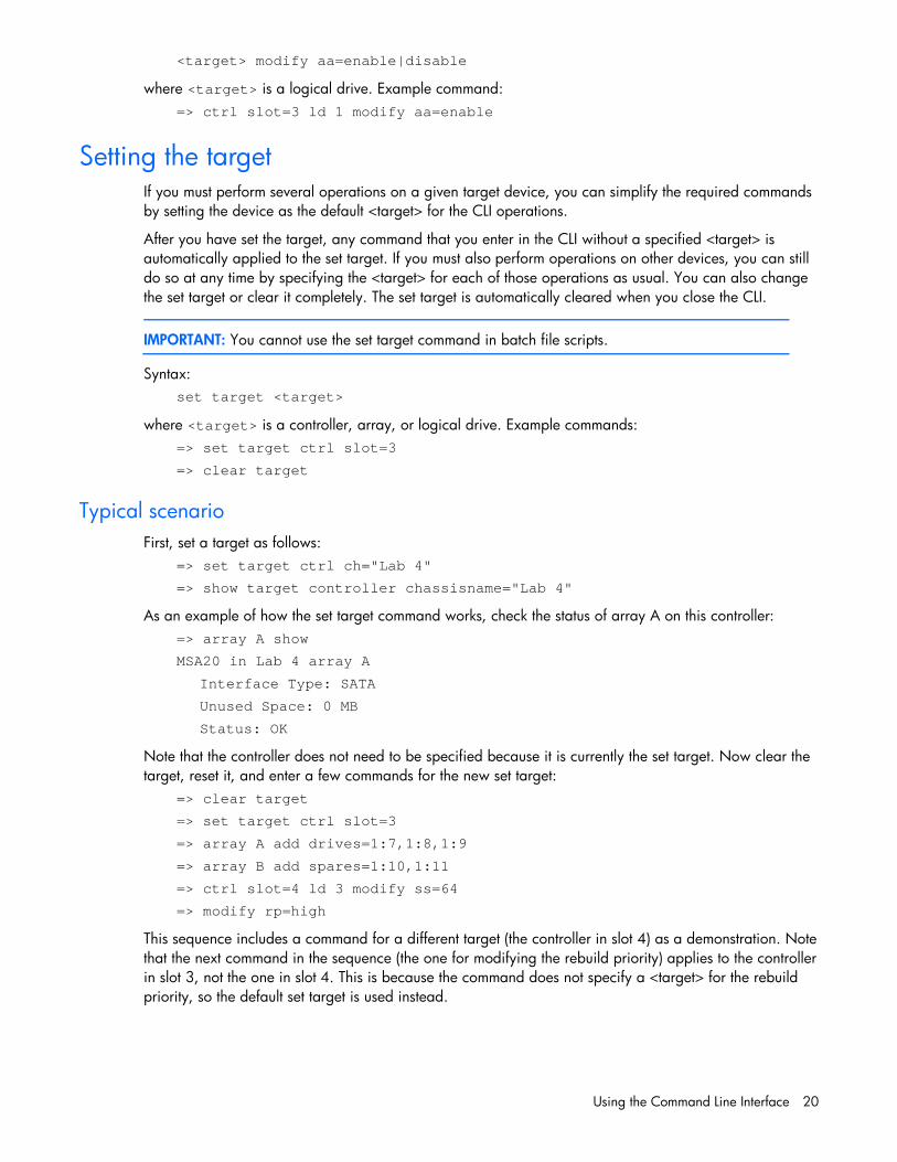
Setting the targetIf you must perform several operations on a given target device, you can simplify the required commands
by setting the device as the default <target> for the CLI operations.
After you have set the target, any command that you enter in the CLI without a specified <target> is
automatically applied to the set target. If you must also perform operations on other devices, you can still
do so at any time by specifying the <target> for each of those operations as usual. You can also change
the set target or clear it completely. The set target is automatically cleared when you close the CLI.
IMPORTANT: You cannot use the set target command in batch file scripts.
Syntax:
set target <target>
where <target> is a controller, array, or logical drive. Example commands:
=> set target ctrl slot=3
=> clear target
Typical scenario
First, set a target as follows:
=> set target ctrl ch="Lab 4"
=> show target controller chassisname="Lab 4"
As an example of how the set target command works, check the status of array A on this controller:
=> array A show
MSA20 in Lab 4 array A
Interface Type: SATA
Unused Space: 0 MB
Status: OK
Note that the controller does not need to be specified because it is currently the set target. Now clear the
target, reset it, and enter a few commands for the new set target:
=> clear target
=> set target ctrl slot=3
=> array A add drives=1:7,1:8,1:9
=> array B add spares=1:10,1:11
=> ctrl slot=4 ld 3 modify ss=64
=> modify rp=high
This sequence includes a command for a different target (the controller in slot 4) as a demonstration. Note
that the next command in the sequence (the one for modifying the rebuild priority) applies to the controller
in slot 3, not the one in slot 4. This is because the command does not specify a <target> for the rebuild
priority, so the default set target is used instead.

Using the Command Line Interface 21
Rescanning the systemA rescan detects devices that have been added to the system since the previous rescan or since the ACU
CLI was started, whichever is more recent.
Syntax:
Use the word rescan directly at the ACU CLI prompt, without any target device or parameters.
Example command:
rescan
Generating a diagnostic reportThe diag command outputs diagnostic information about a specified controller or all controllers on the
system.
Syntax:
<target> diag <file=filename> [ris=on|off] [xml=on|off] [zip=on|off]
where the following is designated:
• <target> is a controller or all controllers
• <file=filename> designates the target file in which the diagnostic information is saved
• [ris=on|off] determines whether RIS information is or is not included
• [xml=on|off] outputs diagnostic information in formatted XML
• [zip=on|off] compresses the output to a zipped file. Default behavior is uncompressed.
Example commands:
=> ctrl all diag file=c:\allcontrollers.txt xml=on
=> ctrl slot=4 diag file=c:\ctrl_slot4.txt ris=off zip=on
=> ctrl ch="mybox" diag file=mybox.txt ris=on xml=off zip=on
Erasing a physical or logical driveSyntax:
<target> modify [erase
erasepattern=zero|random_zero|random_random_zero][deleteaftererase=yes|n
o]
where the target can be any valid physical drive or logical drive. The option to delete the target after
erasing it is valid only if the target is a logical drive.
To stop an erase process at any time, enter the stoperase command.
Example commands:
=> ctrl slot=3 ld 2 modify erase erasepattern=zero
=> ctrl slot=4 ld=all modify erase erasepattern=random_zero
=> ctrl slot=3 ld 2 modify stoperase

Using the Command Line Interface 22
Entering or deleting a license keySome advanced configuration tasks (available only on certain controller models) can be performed only
after software is installed on the controller and a license key is registered to activate the software.
Syntax:
<target> add [lk=xxxxx-xxxxx-xxxxx-xxxxx-xxxxx]
where the target is any valid controller. The hyphens are optional.
To delete a license key, use a standard delete command but use the license key (not the controller) as
the target:
<target> delete
Example commands:
=> ctrl slot=5 lk=12345-65432-78787-43434-24680 delete
=> ctrl slot=4 add lk=9876543210222224444466666
Shrinking an arraySome controllers may not support this option or may require a license key to enable this feature.
You can shrink the size of an array by removing a drive from an existing array. Observe the following
criteria:
• After the shrink, the array must have sufficient capacity to contain all of the configured logical
volumes.
• You may not remove drives from the array if the resulting number of drives does not support the fault
tolerance (RAID level) of any existing logical drive. For example, if you have an array with four
physical drives and a RAID 5 logical drive, you can remove, at most, one drive, because RAID 5
requires at least three physical drives.
• If the array contains a RAID 1+0 logical drive, you can remove only an even number of drives.
• If the array contains a compound RAID (RAID 50 or RAID 60) logical drive, you can remove drives
only in multiples of the number of parity groups. For example, an array with 10 physical drives and
a RAID 50 logical drive can be shrunk by removing two or four drives only.
Syntax:
<target> remove drives=[#:]#:#-[#:]#:#
where <target> is an array, and the specified physical drives are being removed to shrink the array.
For example, in an existing array (array a), six drives (1e:1:4-1e:1:9) are in use. With all criteria met,
you can shrink the array to four drives by removing the last two drives with the command: <array a>
remove drives=1e:1:8-1e:1:9
Example commands:
Using the Command Line Interface 23
=> array a remove drives=1e:1:12-1e:1:14
=> array b remove drives=1c:1:6-1c:1:7
Moving an arraySome controllers may not support this option or may require a license key to enable this feature.
You can move an array by designating different physical drives for the array. To move the array, each of
the physical drives where the array will reside must meet the following criteria:
• It must be an unassigned drive.
• It must be of the same type as the physical drives currently in the source array (for example, SATA or
SAS).
• The destination drives must have sufficient capacity to hold all the logical drives present in the source
array.
Like array creation and expansion, the useable space in all drives is reduced to the size of the smallest
physical drive in the destination disk set.
Moving an array automatically removes any previously assigned spare drives. If spares are assigned to
the existing array, they must be designated for the array when it is moved.
Syntax:
<target> modify drives=[#:]#:#-[#:]#:# spares=[#:]#:#-[#:]#:#
where <target> is an array, and the specified physical drives are the new destination for the array.
For example, in an existing array, three 72-GB SAS drives (1e:1:4-1e:1:6) are the source. Another drive
of the same size is the spare (1e:1:9). With all criteria met, you can move the array to three different 72-
GB SAS drives by specifying the new destination drives in the command (1e:1:12-1e:1:14). To maintain
the same spare drive, be sure to designate the spare drive for the moved array.
Example commands:
=> array a modify drives=1e:1:12-1e:1:14 spares=1e:1:9
=> array b modify drives=1c:1:6-1c:1:7
Secure EraseThe Secure Erase process of ACUCLI erases the data of the selected physical/logical drive. Secure erase
is supported on SAP410i, SAP410, SAP212, SAP712m, and SAP411 controllers. This feature is
available on purchasing/activating the license key for these controllers.
Commands supported: enableeraseddrive
erase erasepattern=zero | random_zero | random_random_zero
deleteaftererase=yes|no
stoperase
Using the Command Line Interface 24
NOTE: Firmware takes a physical drive offline whenever an erase is queued or running. Once the
erase is completed the drive needs to reenabled. If no argument is specified for "erasepattern" by
default "random_random_zero" will be selected.
Examples:
controller slot=5 physicaldrive 1E:1:1 modify enableeraseddrive
controller slot=5 logicaldrive 1 modify erase erasepattern=zerodeleteaftererase=yes
controller slot=5 physicaldrive 1E:1:1 modify erase erasepattern=zero
controller slot=5 logicaldrive 1 modify stoperase
controller slot=5 physicaldrive 1E:1:1 modify stoperase
Advanced Capacity ExpansionHigher capacity migration use capacity transformation to remove logical drives by shrinking and then
expanding them ONLINE. Standard migration and expansion will stay standard. ACE is supported on
SAP410i, SAP410, SAP212 and SAP712m controllers. This feature is available by purchasing and
activating the license key for these controllers.
RAID 60 (fault tolerance)Supported with minimum of 8 drives, with 4 available. Target benefit is to split RAID across the external
boxes. RAID 60 can be supported on all servers. (Blades not supported until JBOD Expander available).
RAID 60 is supported on SAP410i, SAP410, SAP212 and SAP712m controllers. This feature is available
by purchasing and activating the license key for these controllers.

Probability of logical drive failure 25
Probability of logical drive failure
Factors involved in logical drive failureThe probability that a logical drive will fail depends on the RAID-level setting and on the number and type of
physical drives in the array. If the logical drive does not have an online spare, the following results apply:
A RAID 0 logical drive fails if only one physical drive fails.
A RAID 1+0 logical drive fails if any two failed physical drives are mirrored to each other.
○ The maximum number of physical drives that can fail without causing failure of the logical driveis n/2, where n is the number of hard drives in the array. In practice, a logical drive usually failsbefore this maximum is reached. As the number of failed physical drives increases, it becomesincreasingly likely that the newly failed drive is mirrored to a previously failed drive.
○ The minimum number of physical drive failures that can cause the logical drive to fail is two. Thissituation occurs when the two failed drives are mirrored to each other. As the total number ofdrives in the array increases, the probability that the only two failed drives in an array aremirrored to each other decreases.
A RAID 5 logical drive fails if two physical drives fail.
A RAID 6 (ADG) logical drive fails when three physical drives fail.
RAID 50 configurations can tolerate one failed drive in each parity group.
RAID 60 configurations can tolerate two failed drives in each parity group.
At any given RAID level, the probability of logical drive failure increases as the number of physical drives in the
logical drive increases. This principle is illustrated more quantitatively in the graph "Figure 1 Probability of logical
drive failure vs. number of drives in array". The data for this graph is calculated from the MTBF value for a typical
physical drive, assuming that no online spares are present. If an online spare is added to any of the fault-tolerant
RAID configurations, the probability of logical drive failure is further decreased
Figure 1 Probability of logical drive failure vs. number of drives in array

Drive arrays and fault-tolerance methods 26
Drive arrays and fault-tolerance methods
Drive arraysThe capacity and performance of a single physical (hard) drive is adequate for home users. However,
business users demand higher storage capacities, higher data transfer rates, and greater protection
against data loss when drives fail.
Connecting extra physical drives (Pn in the figure) to a system increases the total storage capacity but has
no effect on the efficiency of read/write (R/W) operations. Data can still be transferred to only one
physical drive at a time.

Drive arrays and fault-tolerance methods 27
With an array controller installed in the system, the capacity of several physical drives can be combined
into one or more virtual units called logical drives (also called logical volumes and denoted by Ln in the
figures in this section). Then, the read/write heads of all the constituent physical drives are active
simultaneously, reducing the total time required for data transfer.
Because the read/write heads are active simultaneously, the same amount of data is written to each drive
during any given time interval. Each unit of data is called a block (denoted by Bn in the figure), and
adjacent blocks form a set of data stripes (Sn) across all the physical drives that comprise the logical
drive.
For data in the logical drive to be readable, the data block sequence must be the same in every stripe.
This sequencing process is performed by the array controller, which sends the data blocks to the drive
write heads in the correct order.
A natural consequence of the striping process is that each physical drive in a given logical drive will
contain the same amount of data. If one physical drive has a larger capacity than other physical drives in
the same logical drive, the extra capacity is wasted because it cannot be used by the logical drive.
The group of physical drives containing the logical drive is called a drive array, or just array (denoted by
An in the figure). Because all the physical drives in an array are commonly configured into just one

Drive arrays and fault-tolerance methods 28
logical drive, the term array is often used as a synonym for logical drive. However, an array can contain
several logical drives, each of a different size.
Each logical drive in an array is distributed across all of the physical drives within the array. A logical
drive can also extend across more than one port on the same controller, but it cannot extend across more
than one controller.
Drive failure, although rare, is potentially catastrophic. For arrays that are configured as shown in the
previous figure, failure of any physical drive in the array causes every logical drive in the array to suffer
irretrievable data loss. To protect against data loss due to physical drive failure, logical drives are
configured with fault tolerance.
For any configuration except RAID 0, further protection against data loss can be achieved by assigning a
drive as an online spare (or hot spare). This drive contains no data and is connected to the same
controller as the array. When any other physical drive in the array fails, the controller automatically
rebuilds information that was originally on the failed drive to the online spare. The system is thus restored
to full RAID-level data protection, although it now no longer has an online spare. (However, in the unlikely
event that another drive in the array fails while data is being rewritten to the spare, the logical drive will
still fail.)
When you configure an online spare, it is automatically assigned to all logical drives in the same array.
Additionally, you do not need to assign a separate online spare to each array. Instead, you can configure
one hard drive to be the online spare for several arrays if the arrays are all on the same controller.
Fault-tolerance methodsSeveral fault-tolerance methods exist. Those most often used with Smart Array controllers are hardware-
based RAID methods.
Two alternative fault-tolerance methods that are sometimes used are also described ("
Drive arrays and fault-tolerance methods 29
Alternative fault-tolerance methods"). However, hardware-based RAID methods provide a much more
robust and controlled fault-tolerance environment, so these alternative methods are seldom used.
Hardware-based fault-tolerance methodsHP recommends the following hardware-based methods for use with Smart Array controllers:
RAID 0 — Data Striping only (no fault tolerance)
RAID 1+0 — Drive Mirroring
RAID 5 — Distributed Data Guarding
RAID 6 (ADG) — Advanced Data Guarding
RAID 50 – Striping of Distributed Parity
RAID 60 – Striping of Double Parity
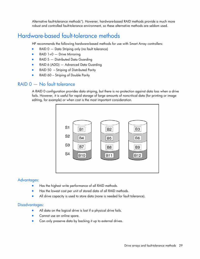
RAID 0 — No fault tolerance
A RAID 0 configuration provides data striping, but there is no protection against data loss when a drive
fails. However, it is useful for rapid storage of large amounts of noncritical data (for printing or image
editing, for example) or when cost is the most important consideration.
Advantages:
Has the highest write performance of all RAID methods.
Has the lowest cost per unit of stored data of all RAID methods.
All drive capacity is used to store data (none is needed for fault tolerance).
Disadvantages:
All data on the logical drive is lost if a physical drive fails.
Cannot use an online spare.
Can only preserve data by backing it up to external drives.

Drive arrays and fault-tolerance methods 30
RAID 1+0 — drive mirroring
In a RAID 1 +0 configuration, data is duplicated to a second drive.
When the array has more than two physical drives, drives are mirrored in pairs.
In each mirrored pair, the physical drive that is not busy answering other requests answers any read
requests that are sent to the array. (This behavior is called load balancing.) If a physical drive fails, the
remaining drive in the mirrored pair can still provide all the necessary data. Several drives in the array
can fail without incurring data loss, as long as no two failed drives belong to the same mirrored pair.
This fault-tolerance method is useful when high performance and data protection are more important than
the cost of physical drives.
NOTE: When there are only two physical drives in the array, this fault-tolerance method is often
referred to as RAID 1.

Drive arrays and fault-tolerance methods 31
Advantages:
Has the highest read performance of any fault-tolerant configuration.
No data is lost when a drive fails, as long as no failed drive is mirrored to another failed drive (upto half of the physical drives in the array can fail).
Disadvantages:
This method is expensive (many drives are needed for fault tolerance).
Only half of the total drive capacity is usable for data storage.
RAID 5 — distributed data guarding
In a RAID 5 configuration, data protection is provided by parity data (denoted by Px,y in the figure). This
parity data is calculated stripe by stripe from the user data that is written to all other blocks within that
stripe. The blocks of parity data are distributed evenly over every physical drive within the logical drive.
When a physical drive fails, data that was on the failed drive can be calculated from the remaining parity
data and user data on the other drives in the array. This recovered data is usually written to an online
spare in a process called a rebuild.
This configuration is useful when cost, performance, and data availability are equally important.
Advantages:
Has high read performance.
Data is not lost if one physical drive fails.
More drive capacity is usable than with RAID 1+0—parity information requires only the storagespace equivalent to one physical drive.
Disadvantages:
Has relatively low write performance.
Data is lost if a second drive fails before data from the first failed drive is rebuilt.
Drive arrays and fault-tolerance methods 32
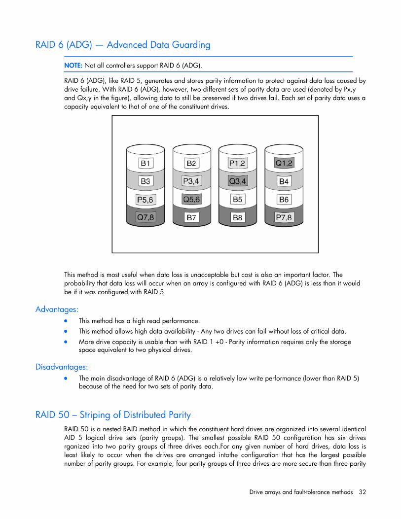
RAID 6 (ADG) — Advanced Data Guarding
NOTE: Not all controllers support RAID 6 (ADG).
RAID 6 (ADG), like RAID 5, generates and stores parity information to protect against data loss caused by
drive failure. With RAID 6 (ADG), however, two different sets of parity data are used (denoted by Px,y
and Qx,y in the figure), allowing data to still be preserved if two drives fail. Each set of parity data uses a
capacity equivalent to that of one of the constituent drives.
This method is most useful when data loss is unacceptable but cost is also an important factor. The
probability that data loss will occur when an array is configured with RAID 6 (ADG) is less than it would
be if it was configured with RAID 5.
Advantages:
This method has a high read performance.
This method allows high data availability - Any two drives can fail without loss of critical data.
More drive capacity is usable than with RAID 1 +0 - Parity information requires only the storagespace equivalent to two physical drives.
Disadvantages:
The main disadvantage of RAID 6 (ADG) is a relatively low write performance (lower than RAID 5)because of the need for two sets of parity data.
RAID 50 – Striping of Distributed Parity
RAID 50 is a nested RAID method in which the constituent hard drives are organized into several identical
AID 5 logical drive sets (parity groups). The smallest possible RAID 50 configuration has six drives
rganized into two parity groups of three drives each.For any given number of hard drives, data loss is
least likely to occur when the drives are arranged intothe configuration that has the largest possible
number of parity groups. For example, four parity groups of three drives are more secure than three parity

Drive arrays and fault-tolerance methods 33
groups of four drives. However, less data can be stored on the array with the larger number of parity
groups.RAID 50 is particularly useful for large databases, file servers, and application servers.
Advantages:
Higher performance than for RAID 5, especially during writes.
Better fault tolerance than either RAID 0 or RAID 5.
Up to n physical drives can fail (where n is the number of parity groups) without loss of data, as longas the failed drives are in different parity groups.
Disadvantages:
All data is lost if a second drive fails in the same parity group before data from the first failed drivehas finished rebuilding.
A greater percentage of array capacity is used to store redundant or parity data than withnonnested RAID methods.
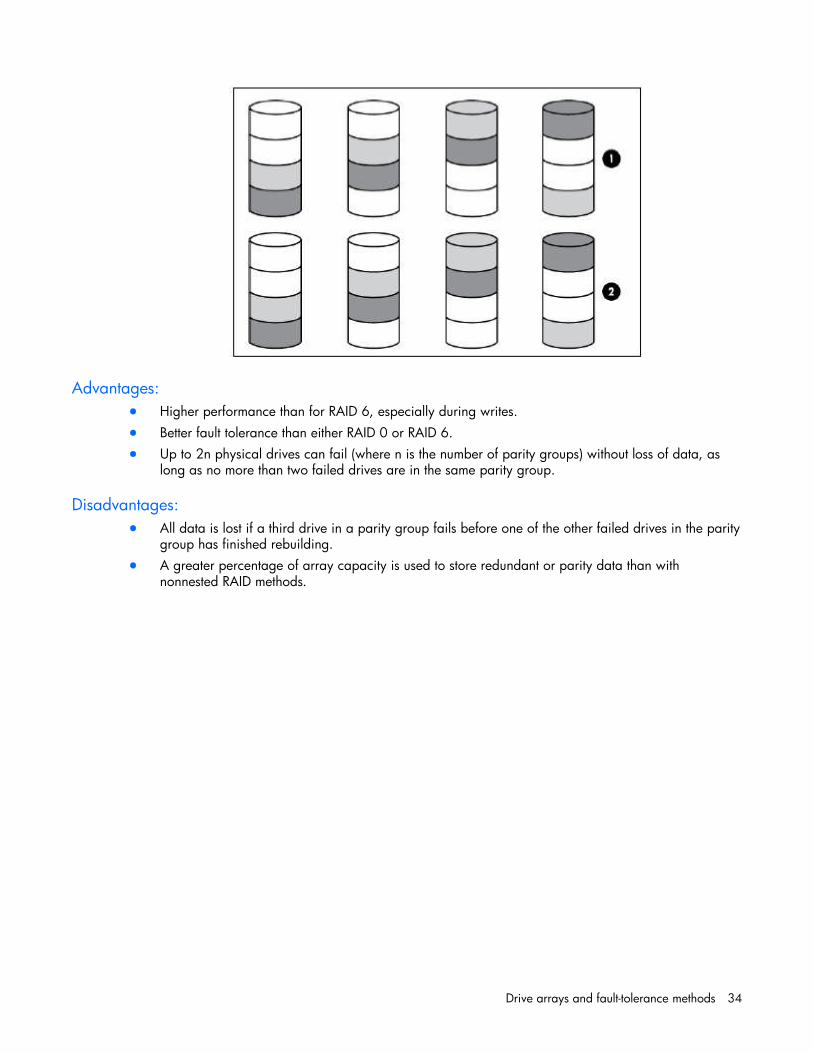
RAID 60 – Striping of Double Parity
RAID 60 is a nested RAID method in which the constituent hard drives are organized into several identical
RAID 6 logical drive sets (parity groups). The smallest possible RAID 60 configuration has eight drives
organized into two parity groups of four drives each.For any given number of hard drives, data loss is
least likely to occur when the drives are arranged into the configuration that has the largest possible
number of parity groups. For example, five parity groups of four drives are more secure than four parity
groups of five drives. However, less data can be stored on the array with the larger number of parity
groups.RAID 60 is particularly useful for data archives and high-availability solutions.
Drive arrays and fault-tolerance methods 34
Advantages:
Higher performance than for RAID 6, especially during writes.
Better fault tolerance than either RAID 0 or RAID 6.
Up to 2n physical drives can fail (where n is the number of parity groups) without loss of data, aslong as no more than two failed drives are in the same parity group.
Disadvantages:
All data is lost if a third drive in a parity group fails before one of the other failed drives in the paritygroup has finished rebuilding.
A greater percentage of array capacity is used to store redundant or parity data than withnonnested RAID methods.

Drive arrays and fault-tolerance methods 35
Comparing the hardware-based RAID methods
NOTE: Not all controllers support RAID 6 (ADG).
Table 4 Create logic drive parameters
Item RAID 0 RAID 1+0 RAID 5 RAID 6 (ADG)
Alternative name Striping (no fault
tolerance)
Mirroring Distributed Data
Guarding
Advanced Data
Guarding
Formula for numberof drives
usable for data (n = total number
of drives in array)
n n/2 n-1 n-2
Fraction of drive space usable* 100% 50% 67% to 93% 50% to 96%
Minimum number of physical
drives
1 2 3 4
Tolerates failure of one physical
drive
No Yes Yes Yes
Tolerates simultaneous failure of
more than one physical drive
No Only if no two
failed drives are
in the same
mirrored pair
No Yes
Read performance High High High High
Write performance High Medium Low Low
Relative cost Low High Medium Medium
*Values for the fraction of drive space usable are calculated with these assumptions: (1) all physical
drives in the array have the same capacity; (2) online spares are not used; (3) no more than 14 physical
drives are used per array for RAID 5; and (4) no more than 56 drives are used with RAID 6 (ADG).
Selecting a RAID method
NOTE: Not all controllers support RAID 6 (ADG).
Table 5 Create logic drive parameters
Most important criterion Also important Suggested RAID level
Fault tolerance Cost effectiveness I/O performance RAID 6 (ADG), RAID 1 +0, RAID 50, RAID 60
Cost effectiveness Fault tolerance I/O performance RAID 6 (ADG)
RAID 5 (RAID 0 if fault tolerance is not required)
I/O performance Cost effectiveness Fault tolerance RAID 5 (RAID 0 if fault tolerance is not required)
RAID 1+0, RAID 50, RAID 60

Drive arrays and fault-tolerance methods 36
Alternative fault-tolerance methodsYour operating system may also support software-based RAID or controller duplexing.
Software-based RAID resembles hardware-based RAID, except that the operating system works with
logical drives as if they were physical drives. To protect against data loss caused by physical drive
failure, each logical drive must be in a different array from the others.
Controller duplexing uses two identical controllers with independent, identical sets of drives containing
identical data. In the unlikely event of a controller failure, the remaining controller and drives will service
all requests.
Neither of these alternative fault-tolerance methods supports online spares or automatic data recovery, nor
do they support auto-reliability monitoring or interim data recovery.
If you decide to use one of these alternative methods, configure your arrays with RAID 0 for maximum
storage capacity and refer to your operating system documentation for further implementation details.

Diagnosing array problems 37
Diagnosing array problems
Diagnostic toolsSeveral diagnostic tools provide feedback about problems with arrays. The most important are:
ADUThis utility is available on both the SmartStart CD and the HP website - http://www.hp.com/support. The
meanings of the various ADU error messages are provided in the HP Servers Troubleshooting Guide.
POST messagesSmart Array controllers produce diagnostic error messages at reboot. Many of these POST messages are
self-explanatory and suggest corrective actions. For more information about POST messages, refer to the
HP Servers Troubleshooting Guide.
Server DiagnosticsTo use Server Diagnostics:
1. Insert the SmartStart CD into the server CD-ROM drive.
2. Click Agree when the license agreement appears, and click the Maintenance tab.
3. Click Server Diagnostics, and follow the on-screen prompts and instructions.
Glossary 38
Glossary
ADG Advanced Data Guarding (also known as RAID 6)
ADU Array Diagnostics Utility
MSA Modular Smart Array
MTBF Mean Time Between Failures
POST Power-On Self Test
Top Related