


Languages
Pages
Legal


Horizontal Production Solutions Presented by Samuel Michaud ICoTA 2011
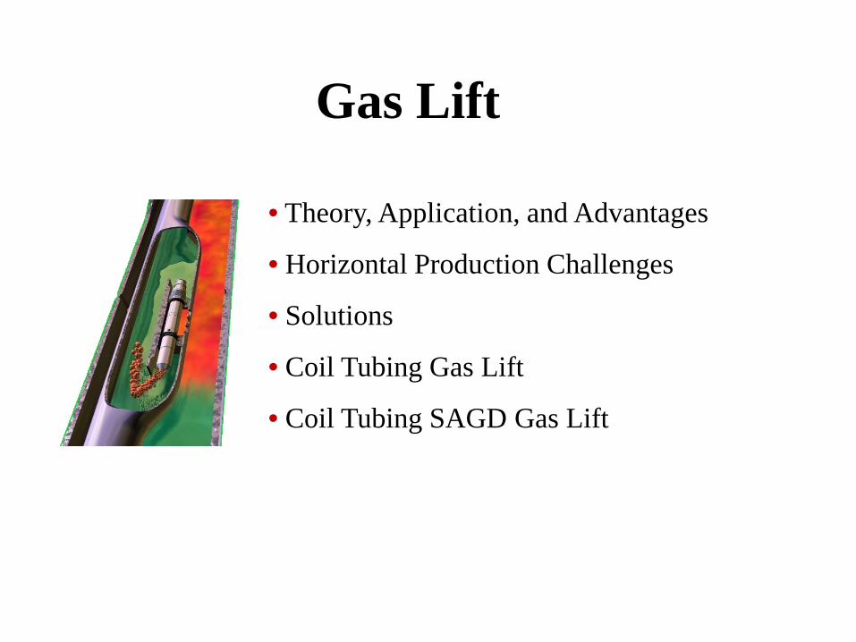
Gas Lift
• Theory, Application, and Advantages
• Horizontal Production Challenges
• Solutions
• Coil Tubing Gas Lift
• Coil Tubing SAGD Gas Lift

• To lift as deep as possible within constraints of production system
• Inject gas requirements through one single valve station
Theory / Application - Gas Lift Objectives and Process

Produced Hydrocarbons Out
Injection Gas In
Side Pocket Mandrel with Gas Lift Valve
Completion Fluid
Side Pocket Mandrel with Gas Lift Valve
Single Production Packer
Side Pocket Mandrel with Gas Lift Valve
Return dead or loaded wells back to production
Increase production in flowing wells
Wide range of production rates
Remove or unload fluids from gas wells and/or keep gas well unloaded
Good operation in high GOR wells
Back flow salt water disposal or injection wells
No moving parts
Sand production not a major problem
Applications

Horizontal Production Challenges
• Challenges with traditional methods of artificial lift providing lift from the HZ section
• Logistics of getting equipment down around the 90 degree heel
• Life span and maintenance of equipment run past 90 degrees • Commonly a lot of sand build-up in HZ section

Horizontal Production– Gas Lift
Injecting gas down the annulus to the crossover packer
At the packer injection gas goes from annulus to tubing and injecting down tubing through horizontal section “sweeping” entire horizontal leg
Formation production is annular flow in the horizontal leg then returning to tubing production in the vertical section via the crossover packer

Coil Tubing Solutions – Gas Lift • Coil tubing gas lift (bull plug / valve) can be run down into
HZ section of tubing with ease • Simple , reliable , minimal intervention to set up • Unloading valves/mandrels can be spliced in to coil if required
(low injection pressure) • No moving parts - no rod wear - nothing to get jammed with
sand • No rig intervention required in most cases, can use existing
tubing string • Locked and packed into any profile nipple • Low BHP wells , extended perforated intervals • Below deviations where it is to risky to run packers

9
Coiled Tubing Gas Lift - Downhole Components
Formation
Injection Gas
Flow Line
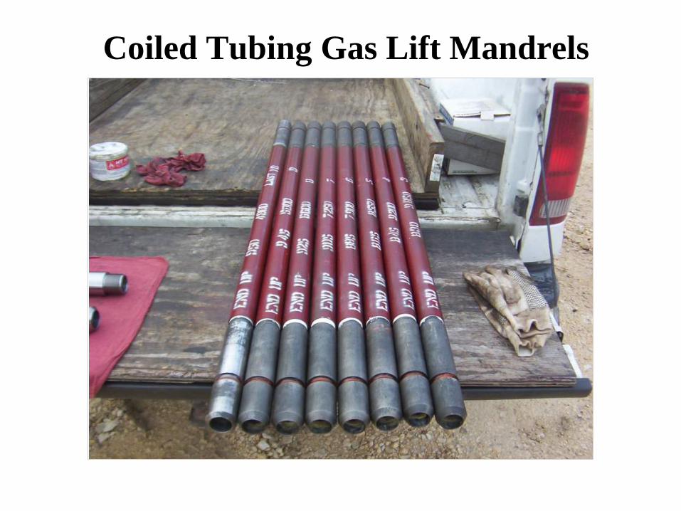
Coiled Tubing Gas Lift Mandrels Valves
Coiled Tubing
Bull Plug

How A Gas Lift Valve Works
3 1/2-in. Casing
1 1/4-in. Coiled Tubing
Gas Lift Valve
Nitrogen Charge
Gas Lift Mandrel

Coil Tubing Gas Lift Valves • Reduced running OD gas lift mandrels with internally
mounted gas lift valves
• CT connectors are installed above and below each mandrel
• These special mandrels and valves are also used in pack-off and slim-hole, jointed pipe gas lift applications
• Provides gas lift applications without pulling well completion
13
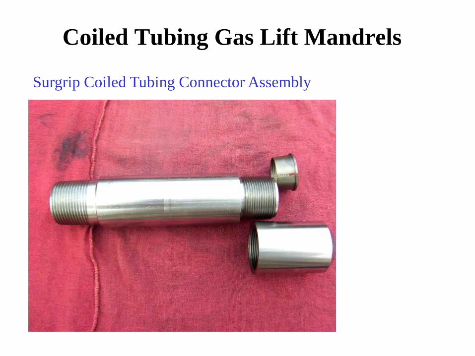
Coiled Tubing Gas Lift Mandrels
Surgrip Coiled Tubing Connector Assembly

Coiled Tubing Gas Lift Surface Components
CT Wellhead Connector
Formation
Injection Gas
Flow Line

Gas Lift Theory / Application - SAGD • Gas lift was one of the first artificial lift choices for SAGD operations. Gas Lift was
chosen due to the low cost and its ability to accommodate the elevated temperature conditions and high fluid production rates.
• Gas lift deployed is a “poor boy” version which is simple completion consisting of production tubing landed in the producing interval – usually two strings one in heel and one near the toe. Coil tubing is run concentrically in the production tubing and gas is injected down the coil and production flows up the tubing (micro-annulus)
• Gas Lift currently accounts for ~ 45% of the market share in SAGD operations • Inject gas into producing conduit to reduce fluid density , thus reducing the gradient • Reduce the FBHP enough to allow fluids to flow to surface without mechanical
interference • Control injection volumes for optimal production • Maintain a stable pressure drop across orifice valve to ensure stable inflow and
consistent injection volumes which are commonly very low ~ 3-5 e3m3/day

Coil Tubing Gas Lift - Evaluation
0 200 400 600 800 1000 1200 14000
200
400
600
800
1000
1200
1400
1600
1800
Offset (meters)Tr
ue V
ert D
epth
(met
ers)
Deviation Profile ( Whd @ 3.40 meters )

Coil Tubing Gas Lift - Evaluation
Inflow OutflowCTbg OD = 19.05 OutflowCTbg OD = 25.40 OutflowCTbg OD = 31.75 OutflowCTbg OD = 38.10OutflowCTbg OD = 44.45
FLOW RATE (m̂ 3/d)35302520151050
FLOW
ING
BTM
PRE
S
(kp
ag)
12000
10000
8000
6000
4000
2000
0
SIZING COIL
Inflow/Outflow Plot - NODAL ANALYSIS - GAS LIFT

Coil Tubing Gas Lift - Evaluation
TVD vs PresQg inj = 999.9 TVD vs PresQg inj = 5000 TVD vs PresQg inj = 10000TVD vs TempQg inj = 999.9 TVD vs TempQg inj = 5000 TVD vs TempQg inj = 10000TVD vs Inj Gas PresQg inj = 999.9 TVD vs Inj Gas PresQg inj = 5000 TVD vs Inj Gas PresQg inj = 10000
PRESSURE (kpag)7000600050004000300020001000
TEMPERATURE (C)70605040302010
TRUE
VER
TICA
L DE
PTH
(
m)
2000
1500
1000
500
0
Pressure Profile
Rate = 25.0 m̂ 3/d
Fluid Properties : Oil Gr = 801.7 Kg/m3 Gas Gr = 0.65 Water Gr = 1.06 WLR = 30.0 % GOR = 100.0 m̂ 3/m̂ 3
Wellbore Data : WHP = 1000.0 kPag TVD = 1678.0 m Corr =Hage/Brown Anul/73.0X31.75/ 2399 Csg/114./ 2799

Coil Tubing Gas Lift - Evaluation
MD vs PresQg inj = 999.9 MD vs PresQg inj = 5000 MD vs PresQg inj = 10000MD vs TempQg inj = 999.9 MD vs TempQg inj = 5000 MD vs TempQg inj = 10000MD vs Inj Gas PresQg inj = 999.9 MD vs Inj Gas PresQg inj = 5000 MD vs Inj Gas PresQg inj = 10000
PRESSURE (kpag)7000600050004000300020001000
TEMPERATURE (C)70605040302010
MEA
SURE
D DE
PTH
(
m)
3000
2500
2000
1500
1000
500
0
Pressure Profile
Rate = 25.0 m̂ 3/d
Fluid Properties : Oil Gr = 801.7 Kg/m3 Gas Gr = 0.65 Water Gr = 1.06 WLR = 30.0 % GOR = 100.0 m̂ 3/m̂ 3
Wellbore Data : WHP = 1000.0 kPag TVD = 1678.0 m Corr =Hage/Brown Anul/73.0X31.75/ 2399 Csg/114./ 2799

Hydraulic Jet Pump
• Theory – How They Work
• Applications – Where/Why They are Used
• Advantages
• Coil Tubing Jet Pumps

Power Fluid
Supply Power Fluid
Pump Energy Source
Power Fluid
Energy Transfer Pump
Production + Exhaust
Power Fluid
The use of high pressure fluids pumped from the surface to drive down-hole pumps.
Theory – How They Work

Power Fluid
Nozzle
Throat
Combination of Fluids
Diffuser
Formation Fluid
Theory – How They Work

Nozzle Throat Diffuser
Power Fluid Pressure
Power Fluid Velocity
PN
Ps Pa
Pd
Theory – How They Work

PN QN
PS QS
Pd Qt
PS QS
Secondary Flow
High Velocity Core
Mixed Flow
Nozzle Throat Diffuser
Theory – How They Work
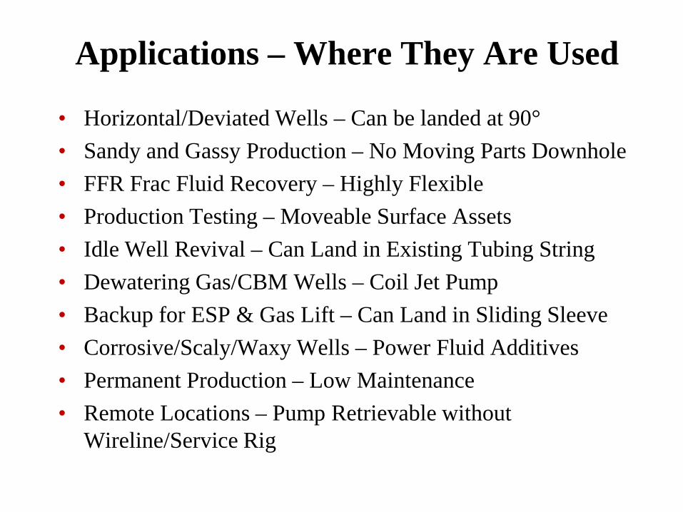
Applications – Where They Are Used
• Horizontal/Deviated Wells – Can be landed at 90° • Sandy and Gassy Production – No Moving Parts Downhole • FFR Frac Fluid Recovery – Highly Flexible • Production Testing – Moveable Surface Assets • Idle Well Revival – Can Land in Existing Tubing String • Dewatering Gas/CBM Wells – Coil Jet Pump • Backup for ESP & Gas Lift – Can Land in Sliding Sleeve • Corrosive/Scaly/Waxy Wells – Power Fluid Additives • Permanent Production – Low Maintenance • Remote Locations – Pump Retrievable without
Wireline/Service Rig

Hydraulic Jet Pump - Advantages • No moving parts downhole • High volume capability • Run and retrieve via wireline or “free”
circulation • Deviated and horizontal wells • No rods in tubing • Tolerant of solids, corrosive fluids, gas • Excellent for producing viscous crude • Adaptable to existing BHA’s and
sliding sleeves • Repairable at well site • Low pump maintenance, easy to
repair

1-1/4 in. Jet “Free” Pump
Power Fluid
Well Fluid
Produced Fluid
Standing Valve
Tubing Packer
Gas
Coiled or Conventional Tubing
Pump Cavity
-Casing Used As Gas Vent for Liquid Wells or Gas Production for Gas Wells
• Installs without pulling tubing • Can be run in directional or
horizontally completed wells • Capable of “free pump” operation;
circulates in and out hydraulically • Jet pump design adaptable to a wide
variety of well conditions and configurations
Coil Tubing Jet Pump

Coil Tubing Jet Pump Wellhead
Injection Line
Production Line
Coil Wellhead Standard Wellhead

• Each jet pump application will have unique surface requirements. • Essentially what is needed: 1. Reservoir Vessel / Separator – Stores produced fluid and power fluid, dumps to
flowline or storage tank. Can act as a separator or be used in conjunction with another separation vessel, provides power fluid to Triplex.
2. Multiplex or HPS Pump – Provides power fluid to the jet pump. Can be fed either from a separation vessel or from water tanks.
Jet Pump Surface Setup - NW Alberta
Jet Pumping – Surface Equipment

Jet Pumping – Surface Equipment
Circulation Valve
Accumulator Vessel
Reservoir
Triplex
Relief Valve
Gas Separator
Fluid Line
Gas Line
H
Relief Valve
Pulsation Dampener
Well Head
Production
Tubing
Lubricator

Issues With Production: • Highly deviated wells • Unknown well capability
Coil Jet Pump Solution: • Produced variable rates from 8 – 130m3/day • Enabled client to develop PI/IPR’s for each well • No operating expenses were incurred to change the nozzles and throats as they were installed “free style” • Pumps have operated with no incidents or downtime
Coil Jet Pump – Case Study

© Copyright 2011 Weatherford ALL RIGHTS RESERVED
THE OPINIONS PROVIDED ARE DELIVERED FOR INFORMATION PURPOSES ONLY AND ON AN “AS IS” BASIS. CLIENT SHALL NOT DISCLOSE
UNLESS EXPRESSLY PERMITTED BY WEATHERFORD. WEATHERFORD MAKES NO WARRANTY, EXPRESS OR IMPLIED, INCLUDING, BUT NOT
LIMITED TO, THE WARRANTIES OF MERCHANTABILITY AND/OR FITNESS FOR A PARTICULAR PURPOSE. ANY ACTION BY CLIENT IS AT ITS OWN RISK