


Languages
Pages
Legal


HEINEMANN® J/S SERIES CIRCUIT BREAKERS
The Power of Reliability
Heinemann® ProductsCommercial Controls Business Unit
Eaton 1936 J/S Circuit Brk Rev1 6/20/02 5:17 PM Page 2

HEINEMANN® CIRCUIT BREAKERS
J/S Series Circuit BreakersDESCRIPTION
Low-cost Heinemann “J”hydraulic magnetic circuitbreakers have long been theOEM designer’s first choice for a wide range ofapplications such as a simplesingle-pole circuit breaker forON/OFF switching withovercurrent protection, or amulti-pole breaker with built-inauxiliary functions for alarm orcontrol purposes.
Small, lightweight Series J/Scircuit breakers are especiallywell suited for use whereequipment must be kept assmall as possible, such as incrowded control panels or inportable or military applications.Additionally, Series J/S circuitbreakers impose minimumpanel mounting restrictions onthe designer. While they arevisually attractive for use onfront panels, they can bemounted out of the way incramped quarters wherenecessary. Because they aremagnetically actuated, Series J/S circuit breakersgenerate negligible heat under load and may beinstalled as close together asrequirements dictate.
For marine installations inclosed areas near a fuel-linejoint, Heinemann offers theMAS and MES breakers withUL recognized ignition-protected construction.
SPECIFICATIONS
Electrical RatingsStandard Maximum Voltages:250V at 50/60 and 400 Hz,65V DC.
Current Rating: Any integral or fractional valuefrom 0.020 to 50A, AC or DC.See table on page 4.
Interrupting Capacities:See table on page 4.
Trip Curves: See page 4.
Environmental DataDesigned to meet therequirements of MIL-C-55629.
Fungus and MoistureResistance: Tested for moistureresistance per MIL-STD-202,Method 106, tested for salt sprayresistance per MIL-STD-202,Method 101. 1 Ferrous partsincorporate special moistureresistant finish. Springs, casesand handles are made fromfungus resistant materials.
Humidity:Tested in accordance withMIL-STD-202, Method 103, test condition “A”.
Shock and Vibration:Tested for shock in accordancewith MIL-STD-202, Method 213,
test condition “I” (100 Gs at sixmilliseconds). Tested forvibration in accordance withMIL-STD-202, Method 204: 10to 500 Hz, 10 Gs, 0.06" totalexcursion on three mutuallyperpendicular planes. Vibrationtests are conducted withbreakers carrying full-ratedcurrent. Shock and vibration
specifications apply to timedelay breakers only.
Operating Temperature Range:-40°C to +85°C.
Dielectric Strength: Tested in accordance withMIL-STD-202, Method 301:1500V 50/60 or 400 Hz; 1100VDC (or twice rating plus 1000V).Meets VDE requirementsof 3750V.
Insulation Resistance:100MΩ minimum at 500V DC,per MIL-STD-202, Method 302.
Endurance:50/60 Hz breakers are subjectedto an endurance test consisting of10,000 ON/OFF operations; 6000at rated current and voltage, 4000at no load.
Approximate Weights: J/1S – 2.5 oz., J/2S – 5 oz.,J/3S – 7.5 oz., J/4S – 10 oz.
Notes:1. Specify voltage-rated coils
separately. Example: CatalogNumber JA1S-A5. Voltagecoil, intermittent-duty, tripson voltage specified, Curve P.
2. Relay trip poles. Alwaysspecify load values for coil
and contacts separately.Standard contact ratingsupplied is 30A. Example:Catalog Number JA1S-B6;coil 5A 65V DC, Curve 3;contacts 30A 250V 50/60Hz. Does not apply to VDE construction.
2
Q Note: Where environment contains concentrations of dirt, grit, dust, pumice or corrosive chemicals, type J/S breakers should be housed in suitable enclosures.
Heinemann is a registered trademark of the Eaton Corporation.
Description . . . . . . . . . . . . . . . .2
Specifications . . . . . . . . . . . . . .2
Trip Curves . . . . . . . . . . . . . . . .4
Internal Circuits . . . . . . . . . .8-10
Dimensions . . . . . . . . . . . .12-15
How to Order . . . . . . . . . . .16-19
Additional Products . . . . .20
TABLE OF CONTENTS Page
Eaton 1936 J/S Circuit Brk Rev1 6/20/02 5:17 PM Page 3

3. UL/CSA models arelabeled with the UL/CSA-rated voltage. Thecatalog number on thebreaker label will containa special suffix A, L orAD indicating a UL/CSAmodel. See page 17.
4. VDE – Approvedbreakers are markedwith the VDE registration#223 for SeriesJ/S breakers.
5. If voltage is rectifier-produced DC, furnishseparately: (a) Full- orhalf-wave rectification,(b) number of phases,(c) filtered or unfiltered.
6. Positive polarity shouldalways be connected tothe terminal marked “Line.”
7. Voltage rated shunt/tapcoils provide tripping online voltage.
APPROVALSSuitable for domestic orworld market applications,the Series J/S (to 30A AC, to50A DC) are UL recognizedas supplementary protectorsunder UL1077 and CSAcertified as components.Approvals include VDE 0660and 0806, IEC 380 and SEV.
For marine installations inclosed areas near a fuel-linejoint, Heinemann offerscircuit breakers with ULrecognized ignition-protected construction.
UL and CSA recognition1, 2, 3 and 4 pole breakersin Series JA/S, JB/S, JC/S,JE/S are recognized as
supplementary protectorsper UL Standard UL 1077(UL File No. E-67155), andcertified in CSA File No. LR-9646-46. Recognition andcertification covers all currentratings from 0.1 to 30A ACand to 50A DC, up to 277VAC maximum, 50/60 Hz; upto 240V maximum, 400 Hz,and up to 65V DC maximum.UL recognition and CSAcertification at 415V, 50/60Hz, refers to 3 pole modelsused only in a three-phrasewye-connected circuit andbacked up with a HeinemannSeries CD3 or CD4 480V100A breaker as groupcontroller, providing aninterrupting capacity of 1500A.
3
JA/S Breaker• Basic JA/S Breaker• Applications: Power supplies, controls systems,
EDP equipment• Easy installation – round boss eliminate
square cuts• Adapter plate to fit existing panels• 1, 2, 3 or 4 pole(s)• Instant color-coding with selection of nine
standards colors• Choice of terminals: Quick-on or screw
JA/S AC/DC Breaker• For AC/DC circuits to 250V 50/60 Hz and to 65V
DC, 0.02 to 30A• Multi-pole versions contain white toggle with
handle tie• 6/32 standard UNC mounting clips• 1, 2 and 3 pole(s)
JB/S Breaker• Snap-in installation through rectangular cutout
reduces need for special installation hardwareor tools
• May be snapped side by side into single openingwhile maintaining constant pole spacing
• Clean matte finish on front escutcheon• 1, 2, 3 or 4 pole(s)
JC/S Breaker• Rocker handle design available in standard
colors: white, gray or black• Custom rocker colors also available• ON and OFF legend are recessed-molded• May be installed on common panel cutout• ON only operation option: Helps prevent
accidental or deliberate shut-off of equipment• 1, 2, 3 or 4 pole(s)
JE/S Breaker• Sealed-mount breaker• Suited for environments where water spray and
splash exist, ie. marine equipment• Panel cutout sealed by O-ring at the base of the
threaded gland bushing• Bright metal ON/OFF switchplate is supplied
as standard• 1, 2 and 3 pole(s)
MAS and MES Breaker• Ignition-protected for use aboard gasoline-
powered marine craft• MAS: Standard toggle handles similar to JA/S• MES: Sealed-mount bat handles similar to JE/S• Current ratings from 0.10 to 30A• Sealed construction will withstand internal are
without igniting an explosive external atmosphere• 1 pole
J Series Product Line Overview
Eaton 1936 J/S Circuit Brk Rev1 6/20/02 5:17 PM Page 4
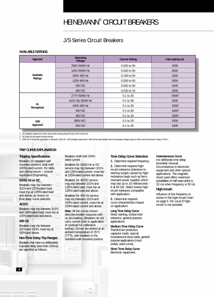
AVAILABLE RATINGS
Approval
AvailableRatings
ULRecognized
VDEApproved
HEINEMANN® CIRCUIT BREAKERS
J/S Series Circuit Breakers
1 AC breakers require four times rated series fusing using K5 fuses (15A minimum).2 DC units do not require backup fusing.3 380V AC is European equivalent to domestic 250V AC. JA/S breakers approved to VDE will be dual labeled with the European voltage rating of 380V and the domestic rating of 250 V.
4
Operating Current Rating Interrupting (A)Voltage
250V 50/60 Hz 0.020 to 50 1000
125V 50/60 Hz 0.020 to 50 2000
250V 400 Hz 0.100 to 50 1000
125V 400 Hz 0.200 to 50 2000
65V DC 0.020 to 50 1000
80V DC 0.020 to 15 1000
277V 50/60 Hz 0.1 to 30 50001
415V 3fy 50/60 Hz 0.1 to 30 1500
240V 400 Hz 0.1 to 30 10001
65V DC 0.1 to 50 10002
80V DC 0.1 to 15 10002
380V AC3 0.1 to 25 1500
65V DC 0.1 to 25 1000
Tripping SpecificationsBreakers (in standard wall-mounted position) shall hold100% rated current. For tableand ceiling mount – consultApplication Engineering.
50/60 Hz or DCBreakers may trip between 101% and 125% rated load;must trip at 125% rated load and above, as shown on time delay curve selected.
AC/DCBreakers may trip between 101%and 135% rated load; must trip at135% rated load and above.
400 HzBreakers may trip between 101% and 150%, must trip at150% and above.
Non-Time Delay Trip RangesBreakers that have no deliberatelyimposed delay (less than 100ms)are specified as follows.
Breakers shall hold 100% rated current.
Breakers for 50/60 Hz or DCservice may trip between 101%and 125% rated current, must tripat 125% rated current and above.
Breakers for AC/DC service may trip between 101% and 135% rated load; must trip at135% rated load and above.
Breakers for 400 Hz servicemay trip between 101% and150% rated current, must trip at150% rated current and above.
Note: All the curves showndescribe breaker response withno pre-loading. (Breakers do notcarry current prior to applicationof overload for calibrationtesting.) Curves are plotted at anambient temperature of 25°C(77°F), with breakers in thestandard wall-mounted position.
Time Delay Curve Selection1. Determine required frequency.
2. Determine required high-inrush tolerance (tolerance tostarting surges caused by high-resistance loads such as ferro-resonant power supplies whichmay last up to 10 milliseconds -8 at 60 Hz). Select lowest high-inrush tolerance compatible with application.
3. Determine requiredcurve characteristics basedon application:
Long Time Delay CurveMotor starting, locked rotortolerance, general purposeapplications.
Medium Time Delay CurveTransformer protection,capacitor loads, specialincandescent lamp loads, generalpurpose applications (mostwidely used curve).
Short Time Delay CurveElectronic equipment.
Instantaneous Curve(no deliberate time delayprovided) Unusualcircumstances in electronicequipment and other specialapplications. The magneticshunt used offers maximumpossibilities on half wave which is10 ms when frequency is 50 Hz.
High-InrushInfluence of line frequency isshown in the high-inrush charton page 5. For curve P, high-inrush is not possible.
TRIP CURVE EXPLANATION
Eaton 1936 J/S Circuit Brk Rev1 6/20/02 5:17 PM Page 5

Nominal DCR and Impedance
DC Delays 60 Hz Delays 400 Hz Delays(Resistance in Ohms) Curves (Impedance in Ohms) Curves (Impedance in Ohms) Curves
Current RatingP-1-2-3 DuCon P-1-2-3 DuConAmperes
10-20-30 251-252-253 2-3-20-30 10-20-30 251-252-253 2-3-20-30 P-1-2-3
0.05 447 730 730 418 836 809 744
0.10 127 182 174 139 176 186 200
0.5 4.12 7.0 6.4 3.99 7.3 6.4 9.36
1 0.86 1.65 1.67 0.917 1.580 1.780 1.74
5 0.050 0.069 0.069 0.051 0.073 0.068 0.074
10 0.014 0.0181 0.0177 0.016 0.0172 0.0158 0.021
15 0.0059 0.0164 0.0146 0.0060 0.0162 0.0155 0.0101
20 0.0045 0.0068 0.0067 0.0046 0.0067 0.0068 0.0060
30 0.0031 0.0028 0.0028 0.0031 0.0031 0.0029 0.0037
50 0.0017 0.0020 0.0019 0.0017 0.0020 0.0019 0.0024
DCR and impedance based on 100% rated current applied and stabilized a minimum of one hour. Tolerance: 0.02A to 2.5A, ±20%; 2.6A to 20A, ±25%; 21A to 50A, ±50%.
5
PERCENT OF RATED CURRENT VS. SECONDS DELAY
Inrush Delay 100% 125% 135% 150% 200% 300% 400% 500% 600% 700% 800% 900% 1000% 1100% 1200%
50/60 Hz 2 No Trip 10 – 110 — 4.5 – 50 1.7 – 18 .55 – 6 .25 – 2.8 .11 – 1.9 .05 – 1.5 .025 – 1.2 .015 – .8 .011 – .41 .01 – .2 .009 – .1 .008 –.05
8x 3 No Trip 1 – 12 — .4 – 5 .15 – 1.9 .054 – .64 .03 – 30 .017 – .2 .01 – 1.4 .007 – .09 .005 – .06 .004 – .05 .004 – .05 .004 – .046 .004 – .04
50/60 Hz10 No Trip 60 – 700 — 30 – 350 10 – 120 3.4 – 42 2 – 22 1.1 – 12.5 .5 – 8 .17 – 5.2 .05 – 4 .02 – 3.4 .01 – 3 .008 – 2.5 .008 – 2
20 No Trip 10 – 110 — 4.5 – 50 1.7 – 18 .54 – 6.9 .3 – 4 .18 – 2.75 .1 – 2 .04 – 1.4 .02 – 1 .013 – .75 .01 – .5 .01 – .25 .01 – 118x
30 No Trip 1 – 12 — .4 – 5 .15 – 1.9 .052 – .73 .03 – .4 .02 – .27 .015 – .2 .012 – .14 .01 – .1 .008 – .074 .006 – .06 .005 – .053 .005 – .05
50/60 Hz251 No Trip 75 – 400 — 35 – 170 15 – 70 5 – 25 3 – 15 2 – 9.5 1.5 – 8 .9 – 7 .5 – 6 .4 – 5 .3 – 5 .2 – 5 .1 – 4
252 No Trip 10 – 100 — 6 – 55 2.5 – 20 .85 – 4.5 .45 – 2.5 .3 – 1.8 .22 – 1.6 .15 – 1.5 .1 – 1.4 .08 – 1.2 .07 – 1 .06 – .9 .05 – .725x
253 No Trip 45 – 345 — .4 – 4.5 .16 – 1.6 .06 –.46 .05 – .4 .04 – .35 .03 – .3 .025 – .25 .02 – .22 .015 – .2 .012 – .15 .009 – .12 .008 – .08
2 No Trip 6 – 80 — 2.5 – 30 .8 – 10 .25 – 3.7 .15 – 2 .09 – 1.2 .05 – .8 .021 – .5 .01 – .3 .006 – .17 .005 – .1 .004 – .06 .004 – .04
3 No Trip 1 – 12 — .4 – 5 .15 – 1.9 .054 – .64 .03 – .3 .017 – .2 .01 – .14 .007 – .09 .005 – .06 .004 – .052 .004 – .05 .004 – .046 .004 – .04
DC 10 No Trip 60 – 700 — 30 – 350 10 – 120 3.4 – 42 2 – 22 1.1 – 12.5 .5 – 8 .17 – 5.2 .05 – 4 .02 – 3.4 .01 – 3 .008 – 2.5 .008 – 2
20 No Trip 10 – 110 — 4.5 – 50 1.7 – 18 .54 – 6.9 .3 – 4 .18 – 2.75 .1 – 2 .04 – 1.4 .02 – 1 .013 – .75 .01 – .5 .01 – .25 .01 – .1
30 No Trip 1 – 12 — .4 – 5 .15 – 1.9 .052 – .73 .03 – .4 .02 – .27 .015 – .2 .012 – .14 .01 – .1 .008 – .074 .006 – .06 .005 – .053 .005 – .05
1 No Trip — — 30 – 350 10 – 120 3.4 – 35 2 – 25 .86 – 19 .25 – 10 .06 – 2.6 .02 – .6 .012 – .25 .01 – .15 .008 – .12 .008 – .1
400 Hz 2 No Trip — — 6 – 70 2.5 – 26 .85 – 8.5 .4 – 5 23 – 3.1 .1 – 2 .02 – 1.1 .01 – .6 .01 – .3 .01 – .15 .009 – .085 .008 – .05
3 No Trip — — .6 – 7 .2 – 2.3 .075 – .84 .04 – .5 .02 – .37 .01 – .25 .006 – .18 .005 – .12 .004 – .075 .004 – .05 .004 – .042 .004 – .04
50/60 Hz 2 No Trip — 7 – 80 4.5 – 50 1.7 – 18 .55 – 6 .25 – 2.8 .11 – 1.9 .05 – 1.5 .025 – 1.2 .015 – .8 .011 – .41 .01 – .2 .009 – .1 .008 – .05
DC 8x 3 No Trip — .6 – 9 .4 – 5 .15 – 1.9 .054 – .64 .03 – .3 .017 – .2 .01 – .14 .007 – .09 .005 – .06 .004 – .052 .004 – .05 .004 – .046 .004 – .04
Non- InstantDelay “P” No Trip .1 .06 .05 .034 .02 .015 .012 .011 .011 .011 .011 .011 .011 .011
Delay Max. Time
TRIP CURVES (CONTINUED)
0%
1000%
% In
10ms 20ms 30msTime
1500%
1800%
2200%
2500%
8ms
7, 8, 9
7, 8, 9
50 Hz60 Hz
4, 5, 6
4, 5, 6
HIGH-INRUSH
Eaton 1936 J/S Circuit Brk Rev1 6/20/02 5:17 PM Page 6

HEINEMANN® CIRCUIT BREAKERS
J/S Series Circuit Breakers – Time Delay Curves
6
0 100
150
.01
.001
.1
1
10
100
1000
10,000
200 300 400 500 600CURRENT – PERCENT OF AMPERE RATING
TRIP
TIM
E –
SECO
NDS
700 800 900 1000 1100 1200125
20 50/60 Hz or DC Medium 18X Hi-Inrush
0 100
150
.01
.001
.1
1
10
100
1000
10,000
200 300 400 500 600CURRENT – PERCENT OF AMPERE RATING
TRIP
TIM
E –
SECO
NDS
700 800 900 1000 1100 1200125
30 50/60 Hz or DC Short 18X Hi-Inrush
0 100
150
.01
.001
.1
1
10
100
1000
10,000
200 300 400 500 600CURRENT – PERCENT OF AMPERE RATING
TRIP
TIM
E –
SECO
NDS
700 800 900 1000 1100 1200125
10 50/60 Hz or DC Long 18X Hi-Inrush
0 100
150
.01
.001
.1
1
10
100
1000
10,000
200 300 400 500 600CURRENT – PERCENT OF AMPERE RATING
TRIP
TIM
E –
SECO
NDS
700 800 900 1000 1100 1200125
251 50/60 Hz Long 25X Hi-Inrush
0 100
150
.01
.001
.1
1
10
100
1000
10,000
200 300 400 500 600CURRENT – PERCENT OF AMPERE RATING
TRIP
TIM
E –
SECO
NDS
700 800 900 1000 1100 1200125
2 50/60 Hz Medium 8X Hi-Inrush
0 100
150
.01
.001
.1
1
10
100
1000
10,000
200 300 400 500 600CURRENT – PERCENT OF AMPERE RATING
TRIP
TIM
E –
SECO
NDS
700 800 900 1000 1100 1200125
3 50/60 Hz Short 8X Inrush
0 100
150
.01
.001
.1
1
10
100
1000
10,000
200 300 400 500 600CURRENT – PERCENT OF AMPERE RATING
TRIP
TIM
E –
SECO
NDS
700 800 900 1000 1100 1200135
2 DC 50/60 Hz Medium 8X Inrush
0 100
150
.01
.001
.1
1
10
100
1000
10,000
200 300 400 500 600CURRENT – PERCENT OF AMPERE RATING
TRIP
TIM
E –
SECO
NDS
700 800 900 1000 1100 1200135
3 DC 50/60 Hz Short 8X Inrush
Eaton 1936 J/S Circuit Brk Rev1 6/20/02 5:17 PM Page 7

Time Delay Curves
7
0 100
150
.01
.001
.1
1
10
100
1000
10,000
200 300 400 500 600CURRENT – PERCENT OF AMPERE RATING
TRIP
TIM
E –
SECO
NDS
700 800 900 1000 1100 1200125
252 50/60 Hz Medium 25X Hi-Inrush
0 100
150
.01
.001
.1
1
10
100
1000
10,000
200 300 400 500 600CURRENT – PERCENT OF AMPERE RATING
TRIP
TIM
E –
SECO
NDS
700 800 900 1000 1100 1200125
2 DC Medium 8X Inrush
0 100
150
.01
.001
.1
1
10
100
1000
10,000
200 300 400 500 600CURRENT – PERCENT OF AMPERE RATING
TRIP
TIM
E –
SECO
NDS
700 800 900 1000 1100 1200125
253 50/60 Hz Short 25X Hi-Inrush
0 100
150
.01
.001
.1
1
10
100
1000
10,000
200 300 400 500 600CURRENT – PERCENT OF AMPERE RATING
TRIP
TIM
E –
SECO
NDS
700 800 900 1000 1100 1200125
3 DC Short 8X Inrush
0 100
150
.01
.001
.1
1
10
100
1000
10,000
200 300 400 500 600CURRENT – PERCENT OF AMPERE RATING
TRIP
TIM
E –
SECO
NDS
700 800 900 1000 1100 1200
1 400 Hz Long 8X Inrush
0 100
150
.01
.001
.1
1
10
100
1000
10,000
200 300 400 500 600CURRENT – PERCENT OF AMPERE RATING
TRIP
TIM
E –
SECO
NDS
700 800 900 1000 1100 1200
2 400 Hz Medium 8X Inrush
0 100
150
.01
.001
.1
1
10
100
1000
10,000
200 300 400 500 600CURRENT – PERCENT OF AMPERE RATING
TRIP
TIM
E –
SECO
NDS
700 800 900 1000 1100 1200
3 400 Hz Short 8X Inrush
0 100
150
.01
.001
.1
1
10
100
1000
10,000
200 300 400 500 600
CURRENT – PERCENT OF AMPERE RATING
TRIP
TIM
E –
SECO
NDS
700 800 900 1000 1100 1200125
P 50/60 Hz / DC / 400 Hz Instant Delay (max. time)
Eaton 1936 J/S Circuit Brk Rev1 6/20/02 5:17 PM Page 8

HEINEMANN® CIRCUIT BREAKERS
J/S Series Circuit Breakers
Q Alarm switch only actuated with electrical trip.
C (11)
NO (14)
NC (12)
Line (1)
Load (2)
Line (1)
Load (2)
C (11)
NO (14)
NC (12)
Line (1)
Load (2)
Line (1) B
Load (2) A
Shunt (3) D
8
INTERNAL CIRCUITS
Circuit Diagrams Description Auxiliary Inrush CodesContact
No 0
Switch only (without Switch coil) with or without
auxiliary contact.
Yes 12
No 8x 3
The contacts and the coil Series Trip are in series. It is often No 25x 8
used as the main switch.
No 25x 38
Yes 8x 2
The contacts and the Series coil are in series. Auxiliary
Trip With contacts are placed behind Yes 25x 9Auxiliary the circuit breaker and Contact mechanically connected
to the releasing system.
Yes 25x 39Q
Enables two loads to be checked by means of a single
No 8x 5circuit breaker. Only releases if there is an overload in the main circuit. Sum of two
Shunt Tap nominal currents must not exceed the peak current of the contacts. Also possible
No 25x 32to adjust tripping through a potentiometer betweenload terminals.
Eaton 1936 J/S Circuit Brk Rev1 6/20/02 5:17 PM Page 9

2 Code 63: With flying leads Ducon terminals, further information on request.
Line (1) B
Load (2) C
Relay (A1) D
Relay (A2) A
Line (1) B
Load (2) A
Shunt (3) D
Line (1) B
Load (2) A
Shunt (3) D
Line (1) B
Load (2) A
Relay (A2) D
Relay (A1) C
U
9
INTERNAL CIRCUITS (CONTINUED)
Circuit Diagrams Description Auxiliary Inrush CodesContact
No 8x 6
Relay Trip
No 25x 23
No 8x 7Dual rating circuit breakersare suitable for apparatusoperating under two
Dual Rating different currents or voltages. As far as possible, the currents must be in the ratio of one to two with a maximum of 25 to 50 A. No 25x 27
This version is used both No 8x 15
for the protection of the Dual load finding itself in series
Control with the circuit breaker and (Ducon) for the release via a voltage.
The main coil is in series with the contact and the Ducon coil is shunt trip. No 25x 25
No 8x 16
Dual ControlDucon Same function as codes 15
(Series + and 25, but both coils are No 25x 26Relay) electrically separated.
Yes 8x 632
For releasing the circuit breakerby the intermediary of a monitoror a safety device installed at adistance. Contacts areelectrically separated from thecoil. All the currents and voltageswithin the permissible limits canbe used. Coils are either currentor voltage sensitive. Can besupplied on request with adielectric strength ranging up to2500 V on alternating current50/60 Hz between the coil andthe contacts.
Eaton 1936 J/S Circuit Brk Rev1 6/20/02 5:17 PM Page 10

HEINEMANN® CIRCUIT BREAKERS
J/S Series Circuit Breakers
10
These internal circuits have nomain contact. When combinedwith another pole, they permitcompliance with the safetyregulations dictated by IEC 950.
The required minimum creepdistance between twogalvanically separated electriccircuits can thus be attained.
No 8x 86Relay Trip
(safetyexecution)
No 8x 98
Yes 8x 99
Mid Trip
Circuit Diagrams Description Auxiliary Inrush CodesContact
Line (1) B
Load (2) A
Shunt (3) D
C (11)
NO (14)
NC (12)
Line (1)
Load (2)
Internal Circuit represented: 98, 99
Internal Circuit represented: 76, 86, 96
Series overload. Mid-trip handle position.
Eaton 1936 J/S Circuit Brk Rev1 6/20/02 5:17 PM Page 11

Color Caps
11
ACCESSORIES
Protective Shield Screw-Type Connectors
Convert quick-on line and load terminals to screw type. Kit contains two quick-on female connectors withscrew termination.
Rating Customer-supplied Crimp-on Connectors
up to 20A ARK-LS Quick-connect female #3000H9AB AMP, Inc. Faston Female #41202 or equivalent.
20 to 30A Hoffman Industrial Products female #DF-1210T-250 or equivalent.
Color Catalog Number
Black 121-76002
Gray 121-76004
Red 121-76005
Green 121-76006
Blue 121-76007
White 121-76008
Yellow 121-76009
Brown 121-76012
Orange 121-76013
Pole Catalog Number
1 006-10211
2 006-10244
3 006-10245
Catalog No. 009-18091
This kit adapts panels cut for Heinemann Series AM/Rbreakers to accept Series JA/S models. Order one kit perpole. Plate fastens to panel with two customer-supplied #6-32 screws.
Adapter Plate
Eaton 1936 J/S Circuit Brk Rev1 6/20/02 5:17 PM Page 12

HEINEMANN® CIRCUIT BREAKERS
J/S Series Circuit Breakers DIMENSIONSDimensions are given hereonly as a preliminary guideto specifying. Final
engineering drawingsshould be made from thelatest Heinemann factorydrawings, available on
request. For metric threads,consult factory.
Tolerance: ±0.81 (0.032)except where noted.
DIMENSIONS APPROXIMATE IN MM (INCHES)
SERIES JA/S
1 2
50.8(2.000)
14.99 Dia.(0.590)
30.99(1.220)
26.67(1.050) 42.16
(1.660)
39.62(1.560)
34.93(1.375)
19.05(0.750)9.53
(0.375)
A A
See Note 56-32 Mounting Clips(Two Per Pole) See Note 3
38.1(1.500)
19.05(0.750)
9.53(0.375)
28.58(1.125)
57.15(2.250)
19.05(0.750)
49.02(1.930)
17.65(0.695)
48.21(1.898)
39.50(1.555)
0.46(0.018)
3.30(0.130)
19.05(0.750)
12.7(0.500)5.59 (0.220)
0.79 (0.031)
27° 5°+–
27° 5°+–
3.96(0.156)
42.16(1.660)
Dia.
26.57(1.046)
15.88 (0.625)± 0.254 (0.010) Dia.
5.08(0.200)
# 8-32 Screws
6.35(0.250)
6.60(0.260)
1.70(0.067) Dia.
Series Trip ConstructionQUICK-ON TERM. A3 B3 C3 A8 B8
ALT. SCREW TERM. T3 V3 W3 T8 V8
NOTE: For screw-type terminals, see VoltageFrequency column on selection table, pages 16 &18. World Market requires screw-type terminals tobe used on ratings above 20A. 1 Pole Panel Cutout
for Multi-Pole Cutouts, use 19.05 (0.750)between center lines.
Section AA
Alternate Terminals
Notes:
1. 0.200 (5.08) is the maximum depthof recess in the breaker foraccommodating mounting screws.When determining the mountingscrew length, do not exceed“mounting panel thickness” plus“0.200 (5.08) dimension.”
2. Breakers shown have handle tiesinstalled. Refer to Handle Locationon selection table, page 18, for various handle configurations.
3. Extended back supplied onbreakers with special functioncircuits. Supplied on otherconstructions at manufacturer’soption.
4. Internal Circuit codes:“A” and “T” = 50/60 Hz.“B” and “V” = DC. “W” = 400 Hz.
5. M3-0.5 pitch, metric mountingthreads available.
6. Handles marked ON/OFF areavailable.
7. Overload protection and/or switchconstruction cannot be supplied inthe same pole as relay trip.
Eaton 1936 J/S Circuit Brk Rev1 6/20/02 5:17 PM Page 13

SERIES JA/S (CONTINUED)
13
DIMENSIONS APPROXIMATE IN MM (INCHES)
Shunt Tap ConstructionQUICK-ON TERM. A5 B5 C5
ALT. SCREW TERM. T5 V5 W518.03
(0.710)
35.0(1.378)
15.49(0.610)
0.79(0.031)
6.35(0.250)
1.70(0.067) Dia.
18.03(0.710)
35.0(1.378)
0.79(0.031)
6.35(0.250)
1.70(0.067) Dia.
SERIES JB/S
OFF
ON
62.23(2.450)
24.26(0.955)
OFF
ON
OFF
ON
43.18(1.700)
OFF
ON
OFF
ON
62.23(2.450)
48.02(1.930)
39.50(1.555)
9.5(0.3
0.317(0.125)
OFF
ON
1 Pole19.56 (0.770)
± 0.254 (0.010)
55.50 (2.187) ± 0.812 (0.032)
2 Pole38.74 (1.525)
± 0.254 (0.010)
3 Pole57.91 (2.280)
± 0.254 (0.010)
Relay Trip ConstructionQUICK-ON TERM.* A86 B86 C86
A6 B6 C6
See Note 4 on page 12
Beveled Panel Mount Bezel – Mounting Code: 24
Panel Cutout
OFF
ON
65.99(2.598)
19.05(0.750)
OFF
ON
OFF
ON
38.1(1.500)
OFF
ON
OFF
ON
57.15(2.250)
48.02(1.930)
39.50(1.555)
9.52(0.375)
0.317(0.125)
OFF
ON
Flush Panel Mount (Matte Finish) – Mounting Code: 00
1 Pole 2 Pole 3 Pole
1 Pole 2 Pole 3 Pole
*Quick-On Terminals for Domestic Markets.
Eaton 1936 J/S Circuit Brk Rev1 6/20/02 5:17 PM Page 14

CIRCUIT BREAKER
J/S Series Circuit BreakersDIMENSIONS APPROXIMATE IN MM (INCHES)
SERIES JC/S
39.50(1.555)
12.7(0.500)
48.21(1.898)
49.02(1.930)
39.62(1.560)
5.59(0.220)
LINE
LOAD
50.8(2.000)0.79
(0.031)
6.35(0.250)
18.67(0.735)
1.70(0.067) Dia.
3.96(0.156) Dia. Hole
34.93(1.375)
42.16(1.660)
21.08(0.830) 15.88
(0.625)
31.75(1.250)
58.80(2.315)
10.41(0.410)
19.05(0.750)
9.53(0.375) 9.53 (0.375)
Rocker Handle Markingand Color as Specified 19.05
(0.750)
9.53(0.375) 19.05
(0.750)19.05
(0.750)
38.1(1.500)
ON
OFF
27.76(1.093)21.08
(0.830)
* 42.16(1.660)
* 46.03(1.812)
* 6-32 Threaded Mtg. Holes Provided at Any One Set of Three Holes Centers Shown
* 52.32(2.060)
35.99(1.417)
23.01(0.906)
30.99(1.220)
ON
OFF
ON
OFF
19.05(0.750)
Typ.
28.58(1.125)
Typ.
57.15(2.250)
57.15(2.250)
Recommended Panel Thickness – 1.02 (0.040)/2.54 (0.100)
ON
OFF
ON
OFF
ON
OFF
Series Trip ConstructionQUICK-ON TERM. A3 B3 A8 B8
ALT. SCREW TERM. T3 V3 T8 V8
Panel Cutout
1 Pole
3 Pole
2 Pole
14
Eaton 1936 J/S Circuit Brk Rev1 6/20/02 5:17 PM Page 15

SERIES JE/S
30.00(1.220)
Wide x Deep Keyway
12.70 (0.50)Wide Nut
50.80(2.000)
9.53(0.375) Dia.
19.05(0.750)
38.10(1.500)
ON/OFF Plate
1.57(0.062)
0.76(0.030)
44.45(1.750)
12.7(0.500)
15.88(0.625)
53.98(2.125)
39.62(1.560)
5.59(0.220)
0.79(0.031)
5.13(0.202) Dia.
6.35(0.250)
1.70(0.067) Dia.
2.49(0.098)
9.53(0.375)
34.93(1.375)
ON
OFF
ON
OFF
O-RingLINE
LOAD
3/8-52 Thread(1/2-32 Thread Available)
Nut
Lock Washer
17°8.5°
SERIES JC/S (CONTINUED)
17.86(0.705)
2.20(0.087)
17.45(0.687)
7.50(0.295)
0.50(0.020)
2.80(0.110)1.30
(0.051)Dia.
C
NO
NC
16.51(0.650)
23.88(0.940)
7.50 (0.295)
7.50 (0.295)0.50 (0.020)
Series-Trip with Auxiliary Switch World/VDE SwitchRated Over 42V Domestic Market Auxiliary SwitchRated 125/250V AC
Series-Trip with Auxiliary Switch World/VDESwitch Rated Under 42V (Contact CustomerService Center for Catalog Number)
DIMENSIONS APPROXIMATE IN MM (INCHES)
Series Trip ConstructionQUICK-ON TERM. A3 B3 C3 A8 B8
ALT. SCREW TERM. T3 V3 W3 T8 V8
Consult factory for 3 pole breakerdimensions *1/2-32 THD. Available
1 Pole 2 Pole
Panel Cutout
15
Eaton 1936 J/S Circuit Brk Rev1 6/20/02 5:17 PM Page 16

HEINEMANN® CIRCUIT BREAKERS
J/S Series Circuit Breakers HOW TO ORDER Standard Circuit Breakers — Series J/STo determine your Complete Catalog Number, start with the appropriate Series Prefix and add the appropriate Code Letters and/or Numbersas in the example below. Any part number with greater than 25 digits including dashes will be shipped with a factory-assigned part number.
There is a choice of up to 6 Frequency and Internal Circuit Poles. Example shows 1 pole.
Product Type Poles SeriesSuffix Voltage Internal
Frequency Circuit
JA 1 S – A 2 –
SELECTION TABLE
Poles
1
2
3
4
N/A Yes Switch 0 –(No Overload Coil)
8X Yes Series Trip 2 –w/Aux. Switch
8X Yes Series Trip 3 –
8X Shunt/Tap 5 –
8X No Relay Trip 6 –
18X Yes Series Trip 8 –
18X Yes Series Trip 9 –w/Aux. Switch
25X Yes Series Trip 38 –
25X Yes Series Trip 39 –w/Aux. Switch
Voltage Frequency
Frequency Terminal Max CodeType Volts
Product Type
Description Handle Color Mounting Codeand Marking Threads
50/60 Hz Push-on 25A A
50/60 Hz #8-32 Screw 30A T
50/60 Hz #10-32 Screw 50A K
DC Push-on 25A B
DC #8-32 Screw 30A V
DC #10-32 Screw 50A L
60 Hz/DC Push-on 25A D
60 Hz/DC #8-32 Screw 30A E
60 Hz/DC #10-32 Screw 50A R
400 Hz Push-on 25A C
400 Hz #8-32 Screw 30A W
400 Hz #10-32 Screw 50A N
Internal Circuit
Inrush VDE Internal CodeCode Approval Circuit
S –
SeriesSuffix
Toggle Handle White On/Off 6-32 JA
Snap-in Mount White On/Off N/A JB
Rocker Handle White On/Off 6-32 JC
Sealed Bat Toggle N/A JE
16
Add each appropriate Number or Letter...
1 If catalog number being specified does not meet the above parameters,see pages 18-19 for non-standard catalog numbers.
2 Handles supplied on each pole (contact Customer Service Center formultipole JE breakers). Handle ties supplied unassembled in kits for multipoleJA breakers. JB and JC multipole units have ties installed.
3 3/8-32 thread on JE1S. Contact Customer Service Center for JE2S and JE3S.4 JE/S Series is only available in 1, 2 and 3 poles.5 Voltage, frequency and internal circuit for first pole on left as viewed
from front panel, or for all pole if identical.
6 Single Letter Code – Add a dash after the internal circuit code. DoubleLetter Code – Remove dash after J__S section and add dash after theinternal circuit code. Ex: JA1SA38-_.
7 Screw terminals available on line and load terminals only. VDE approvedunits require screw terminals above 20A.
8 Please contact Customer Service Center for additional non-standardinternal circuits. Repeat frequency and internal construction steps forsecond and third poles, and subsequent poles if different from first.
9 Please contact Customer Service Center for VDE availability.
Eaton 1936 J/S Circuit Brk Rev1 6/20/02 5:17 PM Page 17

Approval VoltageCurrent
Time Delay Curve Voltage RatingRatings
A – 0030 – 02 E
Approval Voltage
UL CodeApplication
Current Ratings
Ampere
Time Delay Curves
Inrush Time Frequency CodeLevel Delay
Voltage Rating
Rating Code
50/60 Hz8X Long DC 400 Hz – 01
50/60 Hz DC
50/60 Hz8X Medium DC 400 Hz – 02
50/60 Hz DC
50/60 Hz8X Short DC 400 Hz – 03
50/60 Hz DC
50/60 Hz18X Long DC – 10
50/60 Hz DC
50/60 Hz18X Medium DC – 20
50/60 Hz DC
50/60 Hz18X Short DC – 30
50/60 Hz DC
50/60 Hz25X LongDC
– 251
50/60 Hz25X MediumDC
– 252
50/60 Hz25X ShortDC
– 253
50/60 Hz– Instant DC – 0P
400Hz
–Switch
50/60 Hz
OnlyDC – 0S
400 Hz
0-250V AC E
251-277V AC F
415V AC G
0-65V DC N
VDE 380V AC and 65V DC H
From0R20 to 0030
(.2 to 30A)
250V AC,50/60 Hz: 65V DC, A –240V AC, 400 Hz
Non-UL – –Recognized
17
Complete Catalog Number: JA1S–A2–A–0030–02E
0 On multipole units one auxiliary switch is supplied. It is located in the left polewhen viewed from the front of the breaker. See pages 18-19 for non-standardcatalog numbers when additional switches or pole locations are required.
See page 4 for UL-Recognized ratings. Contact Customer Service Centerfor additional UL codes.
Current Rating Code for Standard catalog numbers required a 4 digitcode. Examples: 5A would be 0005; 35A would be 0035. A value lessthan 1A requires a character "R" in place of the decimal point whenordering. Examples: 0.10A would be 0R10; 2.5A would be 02R5.
q See time delay curves on pages 6-7 for required delay.w VDE 0660 approval applies to DC and 50/60 Hz internal circuits listed
under the VDE approval column on the facing page.
Eaton 1936 J/S Circuit Brk Rev1 6/20/02 5:17 PM Page 18

HEINEMANN® CIRCUIT BREAKERS
J/S Series Circuit Breakers HOW TO ORDER Non-standard Circuit Breakers — Series J/STo determine your Complete Catalog Number, start with the appropriate Series Prefix and add the appropriate Code Letters and/or Numbersas in the example below. Any part number with greater than 25 digits including dashes will be shipped with a factory-assigned part number.
SELECTION TABLE
SeriesPrefix
JA
JB
JC
JE
Handle Location
Handle Code
– A
– B
– D
– E
– J
– L
Handle Color& Marking
Color Code& Marking
Mounting Code
Mounting Code
JB/S Snap-in 00Flush Edge
#6-32 UNC Thread 01
M3-0.5 Metric 04Thread
3/8-32 Thread on 11JE1S
1/2-32 Thread onJE1, 2, 3 with 17
additional insert
JB/S Snap-in 24extended side edge
Poles
1
2
3
4
N/A No Switch 0(No Overload Coil)
8X Yes Series Trip 2w/Aux. Switch
8X No Series Trip 3
8X No Shunt/Tap 5
8X No Relay Trip 6
18X Yes Series Trip 8
18X Yes Series Trip 9
8X No DuCon 15
8X No DuCon Series & Relay 16
18X No DuCon with 25Shunt/Tap Voltage Coil
18X No DuCon Series & Relay 26
25X No Series Trip 38
25X Yes Series Trip 39
18X No Relay Coil 86
8X No Mid-trip alarm with 99Alarm Switch
Voltage Frequency
Frequency Terminal Max CodeType Volts
50/60 Hz Push-on 25A A
50/60 Hz #8-32 Screw 30A T
50/60 Hz #10-32 Screw 50A K
DC Push-on 25A B
DC #8-32 Screw 30A V
DC #10-32 Screw 50A L
60 Hz/DC Push-on 25A D
60 Hz/DC #8-32 Screw 30A E
60 Hz/DC #10-32 Screw 50A R
400 Hz Push-on 25A C
400 Hz #8-32 Screw 30A W
400 Hz #10-32 Screw 50A N
Internal Circuit
Inrush Aux. Internal CodeCode Switch Circuit
Black A –ON/OFF
Black I –I-O
White B –ON/OFF
White J –I-O
Red D –ON/OFF
Red L –I-O
Green E –ON/OFF
Green M –I-O
BlackON/OFF AA –
I-O
WhiteON/OFF BB –
I-O
RedON/OFF DD –
I-O
GreenON/OFF EE –
I-O
1 See page 3 for Series descriptions.2 JE/S Series is only available in 1, 2 and 3 poles.3 Voltage, frequency and internal circuit for first pole on left as viewed
from front panel, or for all poles if identical.4 Internal Circuit Diagrams are shown on pages 8 – 10. Please contact
Customer Service Center for additional internal circuits. Repeat frequencyand internal construction steps for second and third poles, and subsequent poles if different from first.
5 Screw terminals available on line and load terminals only. VDE approvedunits require screw terminals above 20A.
6 Please contact Customer Service Center for VDE availability.7 For World Market use. This pole does not contain breaker contacts.8 Other configurations available. Please contact Customer Service Center.9 Available with JA/S Series only.0 Not available with JE/S Series. Handle tie kit is not available with JC/S Series.18
There is a choice of up to 6 Frequency and Internal Circuit Poles. Example shows 2.
SeriesSuffix
Add each appropriate Number or Letter...
S –
SeriesPrefix Poles Series
Suffix Voltage Internal Voltage InternalFrequency Circuit Frequency Circuit
Handle Location
Handle Color& Marking
MountingCode
JA 2 S – A 3 A 2 – L B – 24
Eaton 1936 J/S Circuit Brk Rev1 6/20/02 5:17 PM Page 19

Market
Market Code
Domestic D –
VDE H –Approved
TUVApproved T –and CEMarked
Terminals
Description Code
.250 Push-on A –Terminals
#8-32 Screw B –
#10-32 Screw C –
M4 Thread forCircuit Board P –Connection
M5 Screw F –
M4 Screw V –
Approval Voltage
UL CodeApplication
Auxiliary Switch
Type Rating Terminals Code
SPDT 10A .110 QC 52
SPDT 0.1A .110 QC 54
SPDT 10A .187 QC 07
SPST 10A .187 QC 70
SPST 10A .110 QC 71
SPDT 15A Screw 6-32 72
SPDT 1A Screw 6-32 73
Current Ratings
Ampere
Time Delay Curves
Inrush Time Frequency CodeLevel Delay
50/60 Hz8X Long DC 400 Hz – 01
50/60 Hz DC
50/60 Hz8X Medium DC 400 Hz – 02
50/60 Hz DC
50/60 Hz8X Short DC 400 Hz – 03
50/60 Hz DC
50/60 Hz18X Long DC – 10
50/60 Hz DC
50/60 Hz18X Medium DC – 20
50/60 Hz DC
50/60 Hz18X Short DC – 30
50/60 Hz DC
50/60 Hz25X LongDC
– 251
50/60 Hz25X MediumDC
– 252
50/60 Hz25X ShortDC
– 253
50/60 Hz– Instant DC – 0P
400Hz
–Switch
50/60 Hz
OnlyDC – 0S
400 Hz
Standard color for marking is white except black if used on white.q JE/S Series is available with A and I marking only.w Please contact Customer Service Center for JE2S and JE3S.e VDE approval pending. Only applicable as indicated in Internal Circuit
column on page 18.r TUV approval pending. Only applicable as indicated in Internal Circuit
column on page 18.
t Other auxiliary switches available. Please contact Customer Service Center.y Only 52 and 54 are VDE rated, must be used with World Market/VDE.u All ratings between 0.02A and 30A are available. Contact Customer Service
Center for availability and delivery times. A value less than 1A requires thecharacter “R” in place of the decimal point when ordering. For example,2.5A would be specified as 02R5 in the part number. Ratings above 30Aare available with DC only (10-32 screw terminals required).
19
Complete Catalog Number: JA2S–A3A2–LB–24C–D–L–07–0030–02
From– 0R02 to – 0030
(.2 to 30A)
250V AC,50/60 Hz: 80V DC, A –
240V, 400 Hz
277V AC L –50/60 Hz
415V AC AD –50/60 Hz
Non-UL NU –Recognized
TerminalsUS/European
Approval Voltage Auxiliary SwitchCurrent
Time Delay CurveApprovals Ratings
C – D – L – 07 – 0030 – 02
Eaton 1936 J/S Circuit Brk Rev1 6/20/02 5:17 PM Page 20

KD1 JS DMS AM/R AM1P C GH GJ GJ1P(100-600A)
GJ1P(601-1200A)
10’000 A
50’000 A
1’000 A
100 A
10 A
1 A
Propak
100’000 A
Eaton Corporation Eaton SACommercial Controls Business Unit Commercial Controls Business Unit4201 N. 27th Street CH-1345 Le Lieu, SwitzerlandMilwaukee, WI 53216 Tel: + 41 21 841 9211; Fax: + 41 21 841 9200www.commercialcontrols.eaton.com
Europe and Far East Customer ServiceAmericas Customer Service Tel: + 41 21 841 9211; Fax: + 41 21 841 9200Phone: (800) 962-0820; Phone: (414) 449-6207Fax: (414) 449-6118
Commercial ControlsPublication CB.CAT.JS.01 / C.1 Supersedes Publication DI-129
©2001 Eaton Corporation
CIRCUIT BREAKER SELECTION GUIDE
HEINEMANN® CIRCUIT BREAKERS
For the Widest Selection of Circuit Protection, from 0.01 to 1200 Amperes, Look to Eaton.
Ampere Rating (A) Interrupting Capacity (A) 1 ADS Series for Europe and Asia.
Eaton 1936 J/S Circuit Brk Rev1 6/20/02 5:17 PM Page 1
Top Related