


Languages
Pages
Legal


CHAPTER 2PCU ARCHITECTURE
CHAPTER 3BSS/PCU COMMANDS AND
STATISTICS
CHAPTER 4PCU STATISTICS
CHAPTER 5GSN ARCHITECTURE
CHAPTER 1 GPRS REVIEW

CHAPTER 7SGSN STATISTICS
ATTRIBUTES
CHAPTER 8GGSN STATISTICS
ATTRIBUTES
CHAPTER 9APPENDIX
CHAPTER 10GLOSSARY
CHAPTER 6SGSN CONFIGURATION
PARAMETERS

Network Solutions Sector
GPRS01GPRS ARCHITECTURE
FOR TRAININGPURPOSES
ONLY
ISSUE 1 REVISION 2


FOR TRAININGPURPOSES ONLY
ISSUE 1REVISION 2
GPRS01GPRS
ARCHITECTURE


GPRS01GPRS ARCHITECTURE


�MOTOROLA LTD. 2000 GPRS01: GPRS Architecture
FOR TRAINING PURPOSES ONLY
i
ISSUE 1 REVISION 2
GPRS01GPRS Architecture
� Motorola 1993, 1994, 1995, 1996, 1997, 1998, 1999All Rights ReservedPrinted in the U.K.

ISSUE 1 REVISION 2
�MOTOROLA LTD. 2000GPRS01: GPRS Architecture
FOR TRAINING PURPOSES ONLY
ii
Copyrights, notices and trademarks
CopyrightsThe Motorola products described in this document may include copyrighted Motorola computerprograms stored in semiconductor memories or other media. Laws in the United States and othercountries preserve for Motorola certain exclusive rights for copyright computer programs, including theexclusive right to copy or reproduce in any form the copyright computer program. Accordingly, anycopyright Motorola computer programs contained in the Motorola products described in this documentmay not be copied or reproduced in any manner without the express written permission of Motorola.Furthermore, the purchase of Motorola products shall not be deemed to grant either directly or byimplication, estoppel or otherwise, any license under the copyrights, patents or patent applications ofMotorola, except for the rights that arise by operation of law in the sale of a product.
RestrictionsThe software described in this document is the property of Motorola. It is furnished under a licenseagreement and may be used and/or disclosed only in accordance with the terms of the agreement.Software and documentation are copyright materials. Making unauthorized copies is prohibited bylaw. No part of the software or documentation may be reproduced, transmitted, transcribed, storedin a retrieval system, or translated into any language or computer language, in any form or by anymeans, without prior written permission of Motorola.
AccuracyWhile reasonable efforts have been made to assure the accuracy of this document, Motorolaassumes no liability resulting from any inaccuracies or omissions in this document, or from the useof the information obtained herein. Motorola reserves the right to make changes to any productsdescribed herein to improve reliability, function, or design, and reserves the right to revise thisdocument and to make changes from time to time in content hereof with no obligation to notify anyperson of revisions or changes. Motorola does not assume any liability arising out of the applicationor use of any product or circuit described herein; neither does it convey license under its patentrights of others.
Trademarks
and MOTOROLA are trademarks of Motorola Inc.UNIX is a registered trademark in the United States and other countries, licensed exclusively throughX/Open Company Limited.Tandem , Integrity , Integrity S2 , and Non-Stop-UX are trademarks of Tandem ComputersIncorporated.X Window System , X and X11 are trademarks of the Massachusetts Institute of Technology.Looking Glass is a registered trademark of Visix Software Ltd.OSF/Motif is a trademark of the Open Software Foundation.Ethernet is a trademark of the Xerox Corporation.Wingz is a trademark and INFORMIX is a registered trademark of Informix Software Ltd.SUN, SPARC, and SPARCStation are trademarks of Sun Microsystems Computer Corporation.IBM is a registered trademark of International Business Machines Corporation.HP is a registered trademark of Hewlett Packard Inc.

ISSUE 1 REVISION 2 General information
�MOTOROLA LTD. 2000 GPRS01: GPRS Architecture
FOR TRAINING PURPOSES ONLY
1
General information
Important notice
If this manual was obtained when you attended a Motorola training course, it will not beupdated or amended by Motorola. It is intended for TRAINING PURPOSES ONLY. If itwas supplied under normal operational circumstances, to support a major softwarerelease, then corrections will be supplied automatically by Motorola in the form ofGeneral Manual Revisions (GMRs).
Purpose
Motorola Global System for Mobile Communications (GSM) Technical Education manualsare intended to support the delivery of Technical Education only and are not intended toreplace the use of Customer Product Documentation.
Failure to comply with Motorola’s operation, installation and maintenanceinstructions may, in exceptional circumstances, lead to serious injury or death.
WARNING
These manuals are not intended to replace the system and equipment training offered byMotorola, although they can be used to supplement and enhance the knowledge gainedthrough such training.

ISSUE 1 REVISION 2General information
�MOTOROLA LTD. 2000GPRS01: GPRS Architecture
FOR TRAINING PURPOSES ONLY
2
Cross references
Throughout this manual, cross references are made to the chapter numbers and sectionnames. The section name cross references are printed bold in text.
This manual is divided into uniquely identified and numbered chapters that, in turn, aredivided into sections. Sections are not numbered, but are individually named at the topof each page, and are listed in the table of contents.
Text conventions
The following conventions are used in the Motorola GSM manuals to represent keyboardinput text, screen output text and special key sequences.
Input
Characters typed in at the keyboard are shown like this.
Output
Messages, prompts, file listings, directories, utilities, and environmentalvariables that appear on the screen are shown like this.
Special key sequences
Special key sequences are represented as follows:
CTRL–c Press the Control and c keys at the same time.
ALT–f Press the Alt and f keys at the same time.
| Press the pipe symbol key.
CR or RETURN Press the Return (Enter) key. The Return key isidentified with the ↵ symbol on both the X terminal andthe SPARCstation keyboards. The SPARCstationkeyboard Return key is also identified with the wordReturn.

ISSUE 1 REVISION 2 First aid in case of electric shock
�MOTOROLA LTD. 2000 GPRS01: GPRS Architecture
FOR TRAINING PURPOSES ONLY
3
First aid in case of electric shock
Warning
Do not touch the victim with your bare hands until the electric circuit isbroken.Switch off. If this is not possible, protect yourself with dry insulatingmaterial and pull or push the victim clear of the conductor.
WARNING
Artificialrespiration
In the event of an electric shock it may be necessary to carry out artificial respiration.Send for medical assistance immediately.
Burns treatment
A warning is used to alert the reader to possible hazards that could cause loss of life,physical injury, or ill health. This includes hazards introduced during maintenance, forexample, the use of adhesives and solvents, as well as those inherent in the equipment.
1. Do not attempt to remove clothing adhering to the burn.
2. If help is available, or as soon as artificial respiration is no longer required, coverthe wound with a dry dressing.
3. Do not apply oil or grease in any form.

ISSUE 1 REVISION 2Reporting safety issues
�MOTOROLA LTD. 2000GPRS01: GPRS Architecture
FOR TRAINING PURPOSES ONLY
4
Reporting safety issues
Introduction
A caution means that there is a possibility of damage to systems, or individual items ofequipment within a system. However, this presents no danger to personnel.
Procedure
Whenever a safety issue arises:
1. Make the equipment concerned safe, for example, by removing power.
2. Make no further attempt to tamper with the equipment.
3. Report the problem directly to GSM Customer Network Resolution Centre+44 (0)1793 430040 (telephone) and follow up with a written report by fax+44 (0)1793 430987 (fax).
4. Collect evidence from the equipment under the guidance of the Customer NetworkResolution Centre.

ISSUE 1 REVISION 2 Warnings and cautions
�MOTOROLA LTD. 2000 GPRS01: GPRS Architecture
FOR TRAINING PURPOSES ONLY
5
Warnings and cautions
Introduction
The following describes how warnings and cautions are used in this manual and in allmanuals of the Motorola GSM manual set.
Warnings
Definition
A warning is used to alert the reader to possible hazards that could cause loss of life,physical injury, or ill health. This includes hazards introduced during maintenance, forexample, the use of adhesives and solvents, as well as those inherent in the equipment.
Example and format
Do not look directly into fibre optic cables or optical data in/out connectors.Laser radiation can come from either the data in/out connectors orunterminated fibre optic cables connected to data in/out connectors.
WARNING
Cautions
Definition
A caution means that there is a possibility of damage to systems, or individual items ofequipment within a system. However, this presents no danger to personnel.
Example and format
Do not use test equipment that is beyond its calibration due date when testingMotorola base stations.
CAUTION
ISSUE 1 REVISION 2General warnings
�MOTOROLA LTD. 2000GPRS01: GPRS Architecture
FOR TRAINING PURPOSES ONLY
6
General warnings
Introduction
Observe the following warnings during all phases of operation, installation andmaintenance of the equipment described in the Motorola GSM manuals. Failure tocomply with these warnings, or with specific warnings elsewhere in the Motorola GSMmanuals, violates safety standards of design, manufacture and intended use of theequipment. Motorola assumes no liability for the customer’s failure to comply with theserequirements.
Warning labelsPersonnel working with or operating Motorola equipment must comply with any warninglabels fitted to the equipment. Warning labels must not be removed, painted over orobscured in any way.
Specificwarnings
Warnings particularly applicable to the equipment are positioned on the equipment andwithin the text of this manual. These must be observed by all personnel at all times whenworking with the equipment, as must any other warnings given in text, on the illustrationsand on the equipment.
High voltageCertain Motorola equipment operates from a dangerous high voltage of 230 V ac singlephase or 415 V ac three phase mains which is potentially lethal. Therefore, the areaswhere the ac mains power is present must not be approached until the warnings andcautions in the text and on the equipment have been complied with.
To achieve isolation of the equipment from the ac supply, the mains input isolator mustbe set to off and locked.
Within the United Kingdom (UK) regard must be paid to the requirements of theElectricity at Work Regulations 1989. There may also be specific country legislationwhich need to be complied with, depending on where the equipment is used.
RF radiationHigh RF potentials and electromagnetic fields are present in the base station equipmentwhen in operation. Ensure that all transmitters are switched off when any antennaconnections have to be changed. Do not key transmitters connected to unterminatedcavities or feeders.
Refer to the following standards:
� ANSI IEEE C95.1-1991, IEEE Standard for Safety Levels with Respect to HumanExposure to Radio Frequency Electromagnetic Fields, 3kHz to 300GHz.
� CENELEC 95 ENV 50166-2, Human Exposure to Electromagnetic Fields HighFrequency (10kHz to 300GHz).
Laser radiationDo not look directly into fibre optic cables or optical data in/out connectors. Laserradiation can come from either the data in/out connectors or unterminated fibre opticcables connected to data in/out connectors.

ISSUE 1 REVISION 2 General warnings
�MOTOROLA LTD. 2000 GPRS01: GPRS Architecture
FOR TRAINING PURPOSES ONLY
7
Liftingequipment
When dismantling heavy assemblies, or removing or replacing equipment, the competentresponsible person must ensure that adequate lifting facilities are available. Whereprovided, lifting frames must be used for these operations. When equipments have to bemanhandled, reference must be made to the Manual Handling of Loads Regulations1992 (UK) or to the relevant manual handling of loads legislation for the country in whichthe equipment is used.
Do not ...... substitute parts or modify equipment.
Because of the danger of introducing additional hazards, do not install substitute parts orperform any unauthorized modification of equipment. Contact Motorola if in doubt toensure that safety features are maintained.
Battery supplies
Do not wear earth straps when working with standby battery supplies.
Toxic material
Certain Motorola equipment incorporates components containing the highly toxic materialBeryllium or its oxide Beryllia or both. These materials are especially hazardous if:
� Beryllium materials are absorbed into the body tissues through the skin, mouth, ora wound.
� The dust created by breakage of Beryllia is inhaled.
� Toxic fumes are inhaled from Beryllium or Beryllia involved in a fire.
See the Beryllium health and safety precautions section for further information.

ISSUE 1 REVISION 2Human exposure to radio frequency energy (PCS1900 only)
�MOTOROLA LTD. 2000GPRS01: GPRS Architecture
FOR TRAINING PURPOSES ONLY
8
Human exposure to radio frequency energy (PCS1900 only)
IntroductionThis equipment is designed to generate and radiate radio frequency (RF) energy. Itshould be installed and maintained only by trained technicians. Licensees of the FederalCommunications Commission (FCC) using this equipment are responsible for insuringthat its installation and operation comply with FCC regulations designed to limit humanexposure to RF radiation in accordance with the American National Standards InstituteIEEE Standard C95.1-1991, IEEE Standard for Safety Levels with Respect to HumanExposure to Radio Frequency Electromagnetic Fields, 3kHz to 300GHz.
DefinitionsThis standard establishes two sets of maximum permitted exposure limits, one forcontrolled environments and another, that allows less exposure, for uncontrolledenvironments. These terms are defined by the standard, as follows:
Uncontrolled environment
Uncontrolled environments are locations where there is the exposure of individuals whohave no knowledge or control of their exposure. The exposures may occur in livingquarters or workplaces where there are no expectations that the exposure levels mayexceed those shown for uncontrolled environments in the table of maximum permittedexposure ceilings.
Controlled environmentControlled environments are locations where there is exposure that may be incurred bypersons who are aware of the potential for exposure as a concomitant of employment, byother cognizant persons, or as the incidental result of transient passage through areaswhere analysis shows the exposure levels may be above those shown for uncontrolledenvironments but do not exceed the values shown for controlled environments in thetable of maximum permitted exposure ceilings.
Maximumpermittedexposures
The maximum permitted exposures prescribed by the standard are set in terms ofdifferent parameters of effects, depending on the frequency generated by the equipmentin question. At the frequency range of this Personal Communication System equipment,1930-1970MHz, the maximum permitted exposure levels are set in terms of powerdensity, whose definition and relationship to electric field and magnetic field strengths aredescribed by the standard as follows:
Power density (S)
Power per unit area normal to the direction of propagation, usually expressed in units ofwatts per square metre (W/m2) or, for convenience, units such as milliwatts per squarecentimetre (mW/cm2). For plane waves, power density, electric field strength (E) andmagnetic field strength (H) are related by the impedance of free space, 377 ohms. Inparticular,
� ���
���� ���� ��
where E and H are expressed in units of V/m and A/m, respectively, and S in units ofW/m2. Although many survey instruments indicate power density units, the actualquantities measured are E or E2 or H or H2.

ISSUE 1 REVISION 2 Human exposure to radio frequency energy (PCS1900 only)
�MOTOROLA LTD. 2000 GPRS01: GPRS Architecture
FOR TRAINING PURPOSES ONLY
9
Maximumpermittedexposureceilings
Within the frequency range, the maximum permitted exposure ceiling for uncontrolledenvironments is a power density (mW/cm2) that equals f/1500, where f is the frequencyexpressed in MHz, and measurements are averaged over a period of 30 minutes. Themaximum permitted exposure ceiling for controlled environments, also expressed inmW/cm2, is f/300 where measurements are averaged over 6 minutes. Applying theseprinciples to the minimum and maximum frequencies for which this equipment is intendedto be used yields the following maximum permitted exposure levels:
Uncontrolled Environment Controlled Environment
1930MHz 1970MHz 1930MHz 1970MHz
Ceiling 1.287mW/cm2 1.313mW/cm2 6.433mW/cm2 6.567mW/cm2
If you plan to operate the equipment at more than one frequency, compliance should beassured at the frequency which produces the lowest exposure ceiling (among thefrequencies at which operation will occur).
Licensees must be able to certify to the FCC that their facilities meet the above ceilings.Some lower power PCS devices, 100 milliwatts or less, are excluded from demonstratingcompliance, but this equipment operates at power levels orders of magnitude higher, andthe exclusion is not applicable.
Whether a given installation meets the maximum permitted exposure ceilings depends, inpart, upon antenna type, antenna placement and the output power to which thisequipment is adjusted. The following example sets forth the distances from the antennato which access should be prevented in order to comply with the uncontrolled andcontrolled environment exposure limits as set forth in the ANSI IEEE standards andcomputed above.
ISSUE 1 REVISION 2Human exposure to radio frequency energy (PCS1900 only)
�MOTOROLA LTD. 2000GPRS01: GPRS Architecture
FOR TRAINING PURPOSES ONLY
10
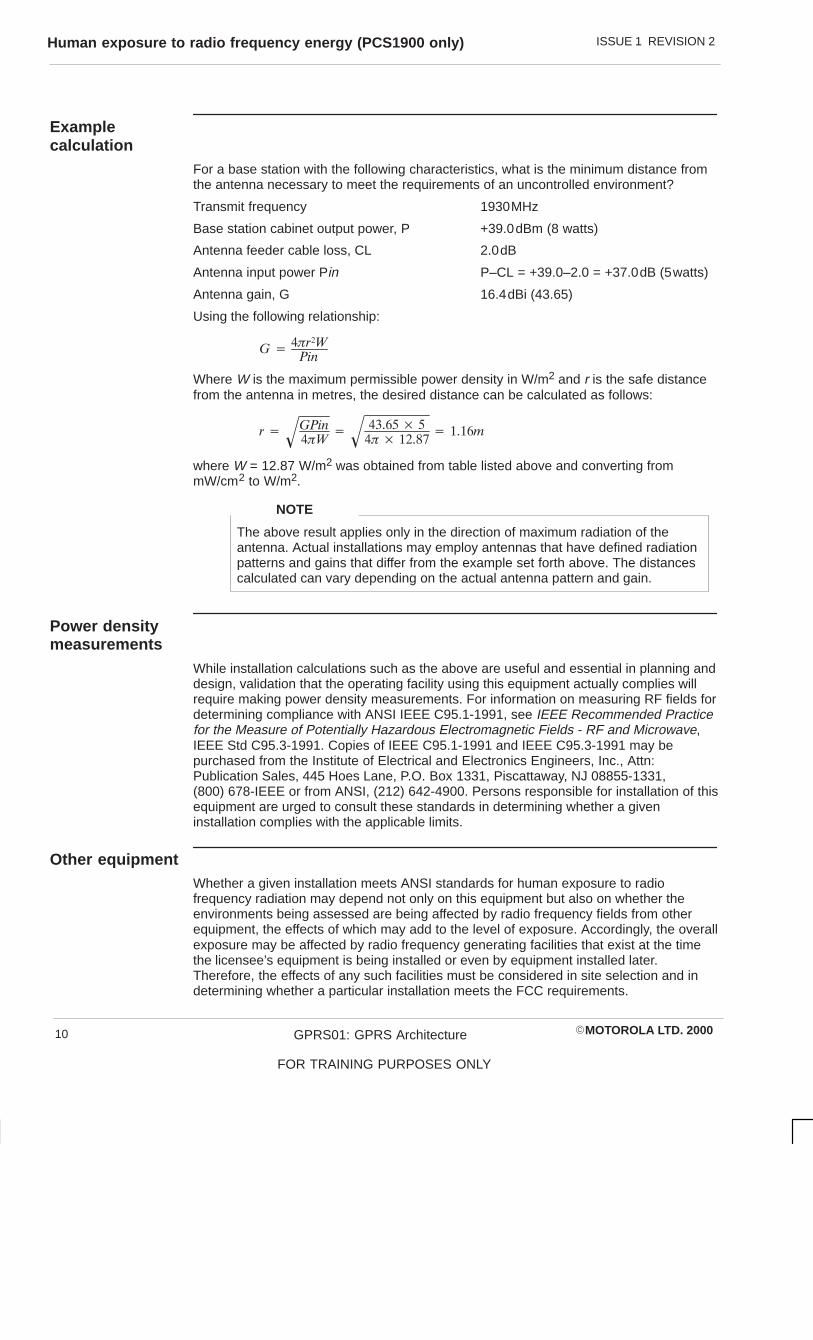
Examplecalculation
For a base station with the following characteristics, what is the minimum distance fromthe antenna necessary to meet the requirements of an uncontrolled environment?
Transmit frequency 1930MHz
Base station cabinet output power, P +39.0dBm (8 watts)
Antenna feeder cable loss, CL 2.0dB
Antenna input power Pin P–CL = +39.0–2.0 = +37.0dB (5watts)
Antenna gain, G 16.4dBi (43.65)
Using the following relationship:
� ������
���
Where W is the maximum permissible power density in W/m2 and r is the safe distancefrom the antenna in metres, the desired distance can be calculated as follows:
� �����
���� �
������ �
��� ������ � �����
where W = 12.87 W/m2 was obtained from table listed above and converting frommW/cm2 to W/m2.
The above result applies only in the direction of maximum radiation of theantenna. Actual installations may employ antennas that have defined radiationpatterns and gains that differ from the example set forth above. The distancescalculated can vary depending on the actual antenna pattern and gain.
NOTE
Power densitymeasurements
While installation calculations such as the above are useful and essential in planning anddesign, validation that the operating facility using this equipment actually complies willrequire making power density measurements. For information on measuring RF fields fordetermining compliance with ANSI IEEE C95.1-1991, see IEEE Recommended Practicefor the Measure of Potentially Hazardous Electromagnetic Fields - RF and Microwave,IEEE Std C95.3-1991. Copies of IEEE C95.1-1991 and IEEE C95.3-1991 may bepurchased from the Institute of Electrical and Electronics Engineers, Inc., Attn:Publication Sales, 445 Hoes Lane, P.O. Box 1331, Piscattaway, NJ 08855-1331,(800) 678-IEEE or from ANSI, (212) 642-4900. Persons responsible for installation of thisequipment are urged to consult these standards in determining whether a giveninstallation complies with the applicable limits.
Other equipmentWhether a given installation meets ANSI standards for human exposure to radiofrequency radiation may depend not only on this equipment but also on whether theenvironments being assessed are being affected by radio frequency fields from otherequipment, the effects of which may add to the level of exposure. Accordingly, the overallexposure may be affected by radio frequency generating facilities that exist at the timethe licensee’s equipment is being installed or even by equipment installed later.Therefore, the effects of any such facilities must be considered in site selection and indetermining whether a particular installation meets the FCC requirements.

ISSUE 1 REVISION 2 Beryllium health and safety precautions
�MOTOROLA LTD. 2000 GPRS01: GPRS Architecture
FOR TRAINING PURPOSES ONLY
11
Beryllium health and safety precautions
Introduction
Beryllium (Be), is a hard silver/white metal. It is stable in air, but burns brilliantly inOxygen.
With the exception of the naturally occurring Beryl ore (Beryllium Silicate), all Berylliumcompounds and Beryllium metal are potentially highly toxic.
Health issues
Beryllium Oxide is used within some components as an electrical insulator. Captive withinthe component it presents no health risk whatsoever. However, if the component shouldbe broken open and the Beryllium Oxide, which is in the form of dust, released, thereexists the potential for harm.
Inhalation
Inhalation of Beryllium Oxide can lead to a condition known as Berylliosis, the symptomsof Berylliosis are similar to Pneumonia and may be identified by all or any of thefollowing:
Mild poisoning causes fever, shortness of breath, and a cough that producesyellow/green sputum, or occasionally bloodstained sputum. Inflammation of the mucousmembranes of the nose, throat, and chest with discomfort, possibly pain, and difficultywith swallowing and breathing.
Severe poisoning causes chest pain and wheezing which may progress to severeshortness of breath due to congestion of the lungs. Incubation period for lung symptomsis 2-20 days.
Exposure to moderately high concentrations of Beryllium in air may produce a veryserious condition of the lungs. The injured person may become blue, feverish with rapidbreathing and raised pulse rate. Recovery is usual but may take several months. Therehave been deaths in the acute stage.
Chronic response. This condition is more truly a general one although the lungs aremainly affected. There may be lesions in the kidneys and the skin. Certain featuressupport the view that the condition is allergic. There is no relationship between thedegree of exposure and the severity of response and there is usually a time lag of up to10 years between exposure and the onset of the illness. Both sexes are equallysusceptible. The onset of the illness is insidious but only a small number of exposedpersons develop this reaction.
First aid
Seek immediate medical assistance. The casualty should be removed immediately fromthe exposure area and placed in a fresh air environment with breathing supported withOxygen where required. Any contaminated clothing should be removed. The casualtyshould be kept warm and at rest until medical aid arrives.

ISSUE 1 REVISION 2Beryllium health and safety precautions
�MOTOROLA LTD. 2000GPRS01: GPRS Architecture
FOR TRAINING PURPOSES ONLY
12
Skin contact
Possible irritation and redness at the contact area. Persistent itching and blisterformations can occur which usually resolve on removal from exposure.
First aid
Wash area thoroughly with soap and water. If skin is broken seek immediate medicalassistance.
Eye contact
May cause severe irritation, redness and swelling of eyelid(s) and inflammation of themucous membranes of the eyes.
First aid
Flush eyes with running water for at least 15 minutes. Seek medical assistance as soonas possible.
Handlingprocedures
Removal of components from printed circuit boards (PCBs) is to take place only atMotorola approved repair centres.
The removal station will be equipped with extraction equipment and all other protectiveequipment necessary for the safe removal of components containing Beryllium Oxide.
If during removal a component is accidently opened, the Beryllium Oxide dust is to bewetted into a paste and put into a container with a spatula or similar tool. The spatula/toolused to collect the paste is also to be placed in the container. The container is then to besealed and labelled. A suitable respirator is to be worn at all times during this operation.
Components which are successfully removed are to be placed in a separate bag, sealedand labelled.
Disposalmethods
Beryllium Oxide or components containing Beryllium Oxide are to be treated ashazardous waste. All components must be removed where possible from boards and putinto sealed bags labelled Beryllium Oxide components. These bags must be given to thesafety and environmental adviser for disposal.
Under no circumstances are boards or components containing Beryllium Oxide to be putinto the general waste skips or incinerated.
Product life cycleimplications
Motorola GSM and analogue equipment includes components containing Beryllium Oxide(identified in text as appropriate and indicated by warning labels on the equipment).These components require specific disposal measures as indicated in the preceding(Disposal methods) paragraph. Motorola will arrange for the disposal of all suchhazardous waste as part of its Total Customer Satisfaction philosophy and will arrangefor the most environmentally ‘friendly’ disposal available at that time.

ISSUE 1 REVISION 2 General cautions
�MOTOROLA LTD. 2000 GPRS01: GPRS Architecture
FOR TRAINING PURPOSES ONLY
13
General cautions
Introduction
Observe the following cautions during operation, installation and maintenance of theequipment described in the Motorola GSM manuals. Failure to comply with thesecautions or with specific cautions elsewhere in the Motorola GSM manuals may result indamage to the equipment. Motorola assumes no liability for the customer’s failure tocomply with these requirements.
Caution labels
Personnel working with or operating Motorola equipment must comply with any cautionlabels fitted to the equipment. Caution labels must not be removed, painted over orobscured in any way.
Specific cautions
Cautions particularly applicable to the equipment are positioned within the text of thismanual. These must be observed by all personnel at all times when working with theequipment, as must any other cautions given in text, on the illustrations and on theequipment.
Fibre optics
The bending radius of all fibre optic cables must not be less than 30 mm.
Static discharge
Motorola equipment contains CMOS devices that are vulnerable to static discharge.Although the damage caused by static discharge may not be immediately apparent,CMOS devices may be damaged in the long term due to static discharge caused bymishandling. Wear an approved earth strap when adjusting or handling digital boards.
See Devices sensitive to static for further information.

ISSUE 1 REVISION 2Devices sensitive to static
�MOTOROLA LTD. 2000GPRS01: GPRS Architecture
FOR TRAINING PURPOSES ONLY
14
Devices sensitive to static
Introduction
Certain metal oxide semiconductor (MOS) devices embody in their design a thin layer ofinsulation that is susceptible to damage from electrostatic charge. Such a charge appliedto the leads of the device could cause irreparable damage.
These charges can be built up on nylon overalls, by friction, by pushing the hands intohigh insulation packing material or by use of unearthed soldering irons.
MOS devices are normally despatched from the manufacturers with the leads shortedtogether, for example, by metal foil eyelets, wire strapping, or by inserting the leads intoconductive plastic foam. Provided the leads are shorted it is safe to handle the device.
Special handlingtechniques
In the event of one of these devices having to be replaced observe the followingprecautions when handling the replacement:
� Always wear an earth strap which must be connected to the electrostatic point(ESP) on the equipment.
� Leave the short circuit on the leads until the last moment. It may be necessary toreplace the conductive foam by a piece of wire to enable the device to be fitted.
� Do not wear outer clothing made of nylon or similar man made material. A cottonoverall is preferable.
� If possible work on an earthed metal surface. Wipe insulated plastic work surfaceswith an anti-static cloth before starting the operation.
� All metal tools should be used and when not in use they should be placed on anearthed surface.
� Take care when removing components connected to electrostatic sensitivedevices. These components may be providing protection to the device.
When mounted onto printed circuit boards (PCBs), MOS devices are normally lesssusceptible to electrostatic damage. However PCBs should be handled with care,preferably by their edges and not by their tracks and pins, they should be transferreddirectly from their packing to the equipment (or the other way around) and never leftexposed on the workbench.

ISSUE 1 REVISION 2 Motorola GSM manual set
�MOTOROLA LTD. 2000 GPRS01: GPRS Architecture
FOR TRAINING PURPOSES ONLY
15
Motorola GSM manual set
Introduction
The following manuals provide the information needed to operate, install and maintain theMotorola GSM equipment.
Generic manuals
The following are the generic manuals in the GSM manual set, these manuals arerelease dependent:
Classificationnumber Name Order number
GSM-100-101 System Information: General 68P02901W01. . . . . . . . . . . . . . . . . . . GSM-100-201 Operating Information: GSM System Operation 68P02901W14. . . GSM-100-202 Operating Information: Scaleable OMC System
Administration 68P02901W19. . . . . . . . . . . . . . . . . . . . . . . . . . . . . . . GSM-100-311 Technical Description: OMC in a GSM System 68P02901W31. . . . GSM-100-313 Technical Description: OMC Database Schema 68P02901W34. . . GSM-100-320 Technical Description: BSS Implementation 68P02901W36. . . . . . . GSM-100-321 Technical Description: BSS Command Reference 68P02901W23. GSM-100-403 Installation & Configuration: GSM System
Configuration 68P02901W17. . . . . . . . . . . . . . . . . . . . . . . . . . . . . . . . GSM-100-423 Installation & Configuration: BSS Optimization 68P02901W43. . . . GSM-100-413 Installation & Configuration: Scaleable OMC
Clean Install 68P02901W47. . . . . . . . . . . . . . . . . . . . . . . . . . . . . . . . . GSM-100-501 Maintenance Information: Alarm Handling at
the OMC 68P02901W26. . . . . . . . . . . . . . . . . . . . . . . . . . . . . . . . . . . . GSM-100-520 Maintenance Information: BSS Timers 68P02901W58. . . . . . . . . . . GSM-100-521 Maintenance Information: Device State Transitions 68P02901W57GSM-100-523 Maintenance Information: BSS Field
Troubleshooting 68P02901W51. . . . . . . . . . . . . . . . . . . . . . . . . . . . . . GSM-100-503 Maintenance Information: GSM Statistics
Application 68P02901W56. . . . . . . . . . . . . . . . . . . . . . . . . . . . . . . . . . GSM-100-721 Software Release Notes: BSS/RXCDR 68P02901W72. . . . . . . . . . GSM-100-712 Software Release Notes: Scaleable OMC System 68P02901W74.
Index of Operations 68P02900W81. . . . . . . . . . . . . . . . . . . . . . . . . . .
Related manuals
The following are related Motorola GSM manuals:
Classificationnumber Name Order number
GSM-001-103 System Information: BSS Equipment Planning 68P02900W21. . . . GSM-002-103 System Information: DataGen 68P02900W22. . . . . . . . . . . . . . . . . . GSM-002-703 Software Release Notes: DataGen 68P02900W76. . . . . . . . . . . . . . GSM-005-103 System Information: Advance Operational Impact 68P02900W25. GSM-008-403 Installation & Configuration: Network Health Analyst 68P02900W36GSM-008-703 Software Release Notes: Network Health Analyst 68P02900W77. GSM-006-202 Operating Information: OMC System
Administration (OSI) 68P02901W10. . . . . . . . . . . . . . . . . . . . . . . . . . GSM-006-413 Installation & Configuration: OSI Clean Install 68P02901W39. . . . . GSM-006-712 Software Release Notes: OMC OSI System 68P02901W70. . . . . .

ISSUE 1 REVISION 2Motorola GSM manual set
�MOTOROLA LTD. 2000GPRS01: GPRS Architecture
FOR TRAINING PURPOSES ONLY
16
Service manuals
The following are the service manuals in the GSM manual set, these manuals are notrelease dependent. The internal organization and makeup of service manual sets mayvary, they may consist of from one to four separate manuals, but they can all be orderedusing the overall catalogue number shown below:
Classificationnumber Name Order number
GSM-100-020 Service Manual: BTS 68P02901W37. . . . . . . . . . . . . . . . . . . . . . . . . . GSM-100-030 Service Manual: BSC/RXCDR 68P02901W38. . . . . . . . . . . . . . . . . . GSM-105-020 Service Manual: M-Cell2 68P02901W75. . . . . . . . . . . . . . . . . . . . . . . GSM-106-020 Service Manual: M-Cell6 68P02901W85. . . . . . . . . . . . . . . . . . . . . . . GSM-201-020 Service Manual: M-Cellcity 68P02901W95. . . . . . . . . . . . . . . . . . . . . GSM-202-020 Service Manual: M-Cellaccess 68P02901W65. . . . . . . . . . . . . . . . . . GSM-203-020 Service Manual: M-Cellarena 68P02902W36. . . . . . . . . . . . . . . . . . . GSM-206-020 Service Manual: M-Cellarenamacro 68P02902W15. . . . . . . . . . . . . . . GSM-205-020 Service Manual: Horizonmacro Indoor 68P02902W06. . . . . . . . . . . GSM-204-020 Service Manual: Horizonmacro Outdoor 68P02902W12. . . . . . . . . . GSM-207-020 Service Manual: Horizonoffice 68P02902W46. . . . . . . . . . . . . . . . . . GSM-101-SERIES ExCell4 Documentation Set 68P02900W50. . . . . . . . . . . . . . . . . . . . GSM-103-SERIES ExCell6 Documentation Set 68P02900W70. . . . . . . . . . . . . . . . . . . . GSM-102-SERIES TopCell Documentation Set (GSM900) 68P02901W80. . . . . . . . . . . GSM-104-SERIES TopCell Documentation Set (DCS1800) 68P02902W80. . . . . . . . . . GSM-200-SERIES M-Cellmicro Documentation Set 68P02901W90. . . . . . . . . . . . . . . . .
Classificationnumber
The classification number is used to identify the type and level of a manual. For example,manuals with the classification number GSM-100-2xx contain operating information.
Order number
The Motorola 68P order (catalogue) number is used to order manuals.
Orderingmanuals
All orders for Motorola manuals must be placed with your Motorola Local Office orRepresentative. Manuals are ordered using the order (catalogue) number. Remember,specify the manual issue required by quoting the correct suffix letter.
ISSUE 1 REVISION 2 GMR amendment
�MOTOROLA LTD. 2000 GPRS01: GPRS Architecture
FOR TRAINING PURPOSES ONLY
17
GMR amendment
Introduction toGMRs
Changes to a manual that occur after the printing date are incorporated into the manualusing General Manual Revisions (GMRs). GMRs are issued to correct Motorola manualsas and when required. A GMR has the same identity as the target manual. Each GMR isidentified by a number in a sequence that starts at 01 for each manual at each issue.GMRs are issued in the form of loose leaf pages, with a pink instruction sheet on thefront.
GMR procedure
When a GMR is received, check on the GMR amendment record page of this manualthat previous GMRs, if any, have been incorporated. If not, contact your administrator orMotorola Local Office to obtain the missing GMRs. Remove and replace pages in thismanual, as detailed on the GMR pink instruction sheet.

ISSUE 1 REVISION 2GMR amendment record
�MOTOROLA LTD. 2000GPRS01: GPRS Architecture
FOR TRAINING PURPOSES ONLY
18
GMR amendment record
Instructions
When a GMR is inserted in this manual, the amendment record below must be filled in torecord the insertion. Retain the pink instruction sheet that accompanies each GMR andinsert it in a suitable place in this manual for future reference.
Amendmentrecord
Record the insertion of GMRs in this manual in the following table:
GMR number Incorporated by (signature) Date
01
02
03
04
05
06
07
08
09
10
11
12
13
14
15
16
17
18
19
20
21
22
23
24
25

ISSUE 1 REVISION 2 GMR amendment record
�MOTOROLA LTD. 2000 GPRS01: GPRS Architecture
FOR TRAINING PURPOSES ONLY
19

�MOTOROLA LTD. 2000 GPRS01: GPRS Architecture
FOR TRAINING PURPOSES ONLY
i
Chapter 1
GPRS Review

ISSUE 1 REVISION 2
�MOTOROLA LTD. 2000GPRS01: GPRS Architecture
FOR TRAINING PURPOSES ONLY
ii

ISSUE 1 REVISION 2
�MOTOROLA LTD. 2000 GPRS01: GPRS Architecture
FOR TRAINING PURPOSES ONLY
iii
Chapter 1GPRS Review i. . . . . . . . . . . . . . . . . . . . . . . . . . . . . . . . . . . . . . . . . . . . . . . . . . . . . . .
Objectives 1–1. . . . . . . . . . . . . . . . . . . . . . . . . . . . . . . . . . . . . . . . . . . . . . . . . . . . . . . . . . . . . . . . .
GPRS Network Overview 1–2. . . . . . . . . . . . . . . . . . . . . . . . . . . . . . . . . . . . . . . . . . . . . . . . . . . . The GPRS Support Node Network (GSN) 1–2. . . . . . . . . . . . . . . . . . . . . . . . . . . . . . . . OMC–G 1–2. . . . . . . . . . . . . . . . . . . . . . . . . . . . . . . . . . . . . . . . . . . . . . . . . . . . . . . . . . . . . The Base Station System (BSS) 1–2. . . . . . . . . . . . . . . . . . . . . . . . . . . . . . . . . . . . . . . . The Mobile Station (MS) 1–2. . . . . . . . . . . . . . . . . . . . . . . . . . . . . . . . . . . . . . . . . . . . . . .
GPRS Application Protocols 1–4. . . . . . . . . . . . . . . . . . . . . . . . . . . . . . . . . . . . . . . . . . . . . . . . . . Base Station System GPRS Protocol (BSSGP) 1–4. . . . . . . . . . . . . . . . . . . . . . . . . . . Logical Link Control (LLC) 1–4. . . . . . . . . . . . . . . . . . . . . . . . . . . . . . . . . . . . . . . . . . . . . . Subnetwork Dependant Convergence Protocol (SNDCP) 1–4. . . . . . . . . . . . . . . . . . . Network Service (NS) 1–6. . . . . . . . . . . . . . . . . . . . . . . . . . . . . . . . . . . . . . . . . . . . . . . . . . GPRS Tunnelling Protocol (GTP) 1–6. . . . . . . . . . . . . . . . . . . . . . . . . . . . . . . . . . . . . . . . Internet Protocol (IP) 1–6. . . . . . . . . . . . . . . . . . . . . . . . . . . . . . . . . . . . . . . . . . . . . . . . . . User Datagram Protocol/Transmission Control Protocol (UDP/TCP) 1–6. . . . . . . . . .
GPRS Review 1–8. . . . . . . . . . . . . . . . . . . . . . . . . . . . . . . . . . . . . . . . . . . . . . . . . . . . . . . . . . . . . . System Overview 1–8. . . . . . . . . . . . . . . . . . . . . . . . . . . . . . . . . . . . . . . . . . . . . . . . . . . . . GPRS 52 Multiframe 1–10. . . . . . . . . . . . . . . . . . . . . . . . . . . . . . . . . . . . . . . . . . . . . . . . . . Um Air Interface 1–12. . . . . . . . . . . . . . . . . . . . . . . . . . . . . . . . . . . . . . . . . . . . . . . . . . . . . . Timeslot Configuration 1–14. . . . . . . . . . . . . . . . . . . . . . . . . . . . . . . . . . . . . . . . . . . . . . . . . Packet Traffic Channels 1–16. . . . . . . . . . . . . . . . . . . . . . . . . . . . . . . . . . . . . . . . . . . . . . . . MS Classes with Multislot Capability 1–18. . . . . . . . . . . . . . . . . . . . . . . . . . . . . . . . . . . . . Fixed Allocation Timeslot Assignment 1–20. . . . . . . . . . . . . . . . . . . . . . . . . . . . . . . . . . . . Mobility Management 1–22. . . . . . . . . . . . . . . . . . . . . . . . . . . . . . . . . . . . . . . . . . . . . . . . . . Timing Advance 1–24. . . . . . . . . . . . . . . . . . . . . . . . . . . . . . . . . . . . . . . . . . . . . . . . . . . . . . . Continuous Timing Advance 1–26. . . . . . . . . . . . . . . . . . . . . . . . . . . . . . . . . . . . . . . . . . . . Mobile Originated Packet Transfer 1–28. . . . . . . . . . . . . . . . . . . . . . . . . . . . . . . . . . . . . . . Downlink Mobile Terminated Packet Transfer 1–30. . . . . . . . . . . . . . . . . . . . . . . . . . . . . Uplink Packet Transfer 1–32. . . . . . . . . . . . . . . . . . . . . . . . . . . . . . . . . . . . . . . . . . . . . . . . . Mobile Terminated Packet Transfer 1–34. . . . . . . . . . . . . . . . . . . . . . . . . . . . . . . . . . . . . . Radio Link Control (RLC) 1–36. . . . . . . . . . . . . . . . . . . . . . . . . . . . . . . . . . . . . . . . . . . . . . . RLC Data ACK/NACK 1–38. . . . . . . . . . . . . . . . . . . . . . . . . . . . . . . . . . . . . . . . . . . . . . . . . Release of Uplink 1–40. . . . . . . . . . . . . . . . . . . . . . . . . . . . . . . . . . . . . . . . . . . . . . . . . . . . . GPRS Attach 1–42. . . . . . . . . . . . . . . . . . . . . . . . . . . . . . . . . . . . . . . . . . . . . . . . . . . . . . . . . GPRS Detach 1–46. . . . . . . . . . . . . . . . . . . . . . . . . . . . . . . . . . . . . . . . . . . . . . . . . . . . . . . . Paging for GPRS Downlink Transfer 1–48. . . . . . . . . . . . . . . . . . . . . . . . . . . . . . . . . . . . . PDP Context Activation 1–50. . . . . . . . . . . . . . . . . . . . . . . . . . . . . . . . . . . . . . . . . . . . . . . . PDP Context Modification Procedure 1–54. . . . . . . . . . . . . . . . . . . . . . . . . . . . . . . . . . . . PDP Context Deactivation 1–54. . . . . . . . . . . . . . . . . . . . . . . . . . . . . . . . . . . . . . . . . . . . . . PDP Context Deactivation Initiated by GGSN Procedure 1–54. . . . . . . . . . . . . . . . . . . Routing Area Update Procedure 1–56. . . . . . . . . . . . . . . . . . . . . . . . . . . . . . . . . . . . . . . . . Combined RA/LA Update in the case of Inter SGSN RA Update Procedure 1–58. .

ISSUE 1 REVISION 2
�MOTOROLA LTD. 2000GPRS01: GPRS Architecture
FOR TRAINING PURPOSES ONLY
iv

ISSUE 1 REVISION 2 Objectives
�MOTOROLA LTD. 2000 GPRS01: GPRS Architecture
FOR TRAINING PURPOSES ONLY
1–1
ObjectivesOn completion of this chapter the student will be able to:
� Identify the functional entities of GPRS
� Describe the GPRS network with regards to GSM
� Identify the GPRS/GSM control channels

ISSUE 1 REVISION 2GPRS Network Overview
�MOTOROLA LTD. 2000GPRS01: GPRS Architecture
FOR TRAINING PURPOSES ONLY
1–2
GPRS Network OverviewThe diagram opposite shows a simplified General Packet Radio Service (GPRS)network. Each network component is illustrated once, however, many of the componentswill occur several times throughout a network.
The principal network component groups are:
The GPRSSupport NodeNetwork (GSN)
The GPRS Support Node Network (GSN) is the main element in the GPRSinfrastructure. It is a high performance, broadband packet switching node that providesconnection and interworking with various data networks, mobility management anddelivery of data packets to mobile stations. The GSN Network is made of the followingcomponent groups.
� CommHub – The GSN CommHub is the central connection point for thecomponents in a GPRS system. It provides LAN connectivity between GPRScomponents through Ethernet and WAN connectivity to data networks outside theGPRS system.
� ISS – The Integrated Support Services provides GPRS system components withthe current time, domain name translation and network information.
� GGSN – The Gateway GPRS Support Node provides network access to externalhosts so they can communicate with MSs. It also decapsulates and forwardsexternal data networks packets to the appropriate data network.
� SGSN – The Serving GPRS Support Node detects and tracks GPRS MSs in itsservice area and provides a reliable, secure data channel as the MS movesbetween cells.
OMC–GThe OMC-G enables operators to use an NT graphical user interface (GUI) whenmanaging the GPRS components. System operators use the OMC–G to configure andmonitor system components and view performance data.
The Base StationSystem (BSS)
The Base Station System provides the radio frequency link between the GPRS networkinfrastructure and mobile subscribers throughout the operational area. A BSS consists ofthree components:
� Base Station Controller (BSC)
� Base Station Transceiver (BTS)
� Packet Control Unit (PCU) – The Packet Control Unit (PCU) performs radiofunctions and GPRS network functions. It has interfaces to the OMC-R, BSC andthe SGSN.
The MobileStation (MS)
The MSs can belong to three classes A, B or C the class determines whether GPRS andCircuit Switched services can be carried out at the same time or not. The mobiles arealso divided in to multi slot classes that determine the mobile capability of sending andreceiving over multiple slots in a TDMA frame.

ISSUE 1 REVISION 2 GPRS Network Overview
�MOTOROLA LTD. 2000 GPRS01: GPRS Architecture
FOR TRAINING PURPOSES ONLY
1–3
For TrainingPurposesOnly
Coursecode –Section ?
MSCBSC
SGSN
GGSN
BTSInternet
Com
mH
ub
ISS
GSN Network
Frame Relay
PCUAbis
GDS
A
Gb
Gi Router
RXCDR
ISSUE 1 REVISION 2GPRS Application Protocols
�MOTOROLA LTD. 2000GPRS01: GPRS Architecture
FOR TRAINING PURPOSES ONLY
1–4
GPRS Application Protocols
Base StationSystem GPRSProtocol(BSSGP)
Base Station System GPRS Protocol uses Frame relay protocol to provide the radiorelated Qualiity Of Service (QOS) and routing information required to transmit user databetween an SGSN and a BSS. In the SGSN, it forms an interface between Radio LinkControl (RLC)/ Media Access Control (MAC) derived information from the BSS andLogical Link Control (LLC) frames from the SGSN. In the BSS, it acts as an interfacebetween LLC frames from the SGSN and RLC/MAC from the BSS.
The functions of the BSSGP protocol are to:
� Provide a connectionless link between the SGSN and the BSS.
� Transfer data unconfirmed between the SGSN and the BSS.
� Provide tools for the bi-directional control of the flow of data between the SGSNand the BSS.
� Handle paging requests from the SGSN to the BSS.
� Give support for the flushing of old messages from the BSS, for example when anMS changes BSSs.
� Support multiple layer 2 links between the SGSN and the BSS.
Logical LinkControl (LLC)
The LLC provides a highly reliable logical connection between the SGSN and the MS andas such spans the Gb and Um interfaces. In addition the LLC has been designed to beindependent of the underlying radio interface protocols. The LLC includes functions for:
� Provision of one or more logical link connections discriminated between by meansof the Service Access Point Identifier (SAPI).
� Sequence Control
� Error detection and Recovery
� Flow Control
� Ciphering
SubnetworkDependantConvergenceProtocol(SNDCP)
Network Layer protocols are intended to be capable of operating over services derivedfrom a wide variety of submetworks and data links. GPRS supports several network layerprotocols providing protocol transparency for the users of the service. Introduction of newnetwork layer protocols to be transferred over GPRS shall be possible without anychanges to GPRS. Therefore, all functions related to the transfer of Network layerProtocol Data Units (N–PDUs) shall be carried out in a transparent way by GPRSnetwork entities using Subnetwork Dependant Convergence Protocol (SNDCP). Anotherfunction of SNDCP is to improve channel efficiency fulfilled by protocol compression anddata compression.

ISSUE 1 REVISION 2 GPRS Application Protocols
�MOTOROLA LTD. 2000 GPRS01: GPRS Architecture
FOR TRAINING PURPOSES ONLY
1–5
GSM RF
LLC
SNDCP
IP
GSM RF
RLC/
MAC
BSSGP
Network
Service
L1 Bis
BSSGP
Network
Service
L1 Bis
LLC
SNDCP
L1
L2
IP
TCP/
UDP
GTP
RLC/
MAC
L1
L2
IP
TCP/
UDP
GTP
IP
MS BSS SGSN GGSN

ISSUE 1 REVISION 2GPRS Application Protocols
�MOTOROLA LTD. 2000GPRS01: GPRS Architecture
FOR TRAINING PURPOSES ONLY
1–6
Network Service(NS)
The Network Service (NS) transports the BSSGP PDUs. The Network Service Controlentity is responsible for the following functions:
� NS SDU transmission: The NS SDUs shall be transmitted on the NS–VCs. The NSSDUs are encapsulated into Network Service Control PDUs, which in turn areencapsulated into Sub–Network Service PDUs.
� Load sharing: The load sharing function distributes the NS SDU traffic amongst theavailable (i.e. unblocked) NS–VCs of a group.
� NS–VC management: A blocking procedure is used by an NS entity to inform anNS peer entity when an NS–VC becomes unavailable for NS user traffic. Anunblocking procedure is used for the reverse operation. A reset procedure is usedbetween peer NS entities in order to set an NS–VC to a determined state, afterevents resulting in possibly inconsistent states of the NS–VC at both sides of theGb interface. A test procedure is used to check that an NS–VC is operatingproperly between peer NS entities.
GPRS TunnellingProtocol (GTP)
GPRS Tunnelling Protocol (GTP) allows multiprotocol packets to be tunnelled throughthe GPRS backbone between GPRS Support Nodes (GSNs). GTP tunnels user data andsignalling between GSNs in the GPRS network. GTP uses Transmission ControlProtocol/Internet Protocol (TCP/IP) and User Datagram Protocol/Internet Protocol(UDP/IP) protocols to communicate between SGSN and GGSN. GTP simultaneouslysupports two operation modes for information transfer between the GGSN and theSGSN: acknowledged and unacknowledged.
Internet Protocol(IP)
Internet Protocol is the GPRS protocol used for routing user data and control signallingwithin the GSN, as well as from the Internet.
User DatagramProtocol/Transmission ControlProtocol(UDP/TCP)
User Datagram Protocol (UDP) carries GTP PDUs for protocols that do not need areliable data link. UDP also provides protection against corrupted GTP PDUs.
Transmission Control Protocol (TCP)_carries GTP PDUs for protocols requiring reliabledata link. TCP also provides flow control and protection against lost and corrupted GTPPDUs.

ISSUE 1 REVISION 2 GPRS Application Protocols
�MOTOROLA LTD. 2000 GPRS01: GPRS Architecture
FOR TRAINING PURPOSES ONLY
1–7
GSM RF
LLC
SNDCP
IP
GSM RF
RLC/
MAC
BSSGP
Network
Service
L1 Bis
BSSGP
Network
Service
L1 Bis
LLC
SNDCP
L1
L2
IP
TCP/
UDP
GTP
RLC/
MAC
L1
L2
IP
TCP/
UDP
GTP
IP
MS BSS SGSN GGSN

ISSUE 1 REVISION 2GPRS Review
�MOTOROLA LTD. 2000GPRS01: GPRS Architecture
FOR TRAINING PURPOSES ONLY
1–8
GPRS Review
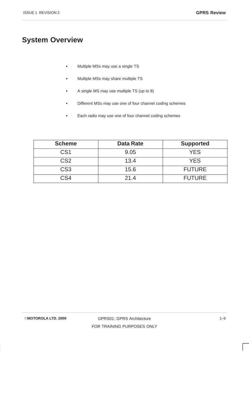
SystemOverview
GPRS is a set of new GSM Bearer and Teleservices providing Packet modeTransmission with the PLMN and external networks. It allows the MSs to send andreceive data in an end to end packet transfer without using resources used for circuitswitches.
GPRS will be able to provide both Point to Point (PTP) and Point to Multipoint (PTM).
The GSM radio is broken down for efficient use by data users.
� Multiple MSs may use a single timeslot
� Multiple MSs may share multiple timeslots
� A single MS may use multiple timeslots (up to eight)
� Different MSs may use uplink or downlink radio resource
� Each radio may use one of four channel coding schemes to get up to 21.4kbps ofdata per timeslot
The channel coder firmware will support CS1 and CS2 for GPRS at GSNI.
Scheme Data Rate Supported
CS1 9.05 YES
CS2 13.4 YES
CS3 15.6 NO
CS4 21.4 NO
ISSUE 1 REVISION 2 GPRS Review
�MOTOROLA LTD. 2000 GPRS01: GPRS Architecture
FOR TRAINING PURPOSES ONLY
1–9
System Overview
� Multiple MSs may use a single TS
� Multiple MSs may share multiple TS
� A single MS may use multiple TS (up to 8)
� Different MSs may use one of four channel coding schemes
� Each radio may use one of four channel coding schemes
Scheme Data Rate Supported
CS1 9.05 YES
CS2 13.4 YES
CS3 15.6 FUTURE
CS4 21.4 FUTURE
ISSUE 1 REVISION 2GPRS Review
�MOTOROLA LTD. 2000GPRS01: GPRS Architecture
FOR TRAINING PURPOSES ONLY
1–10
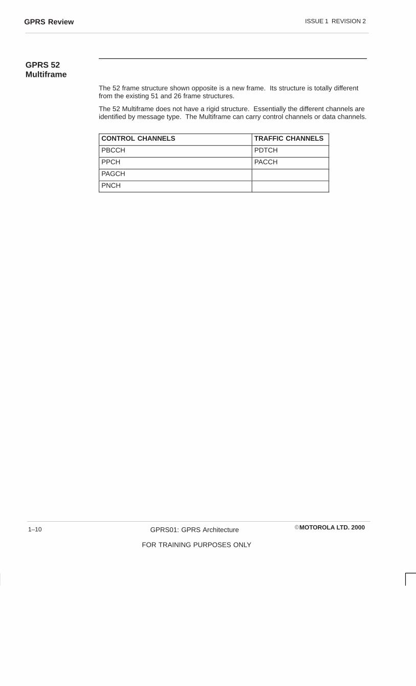
GPRS 52Multiframe
The 52 frame structure shown opposite is a new frame. Its structure is totally differentfrom the existing 51 and 26 frame structures.
The 52 Multiframe does not have a rigid structure. Essentially the different channels areidentified by message type. The Multiframe can carry control channels or data channels.
CONTROL CHANNELS TRAFFIC CHANNELS
PBCCH PDTCH
PPCH PACCH
PAGCH
PNCH

ISSUE 1 REVISION 2 GPRS Review
�MOTOROLA LTD. 2000 GPRS01: GPRS Architecture
FOR TRAINING PURPOSES ONLY
1–11
52 Multiframe structure
B0
B1
B2
�
B3
B4
B5
�
B6
B7
B8
�
B9
B10
B11
�
�
��= IDLE FRAMEB(n)= 4 Frame radio block

ISSUE 1 REVISION 2GPRS Review
�MOTOROLA LTD. 2000GPRS01: GPRS Architecture
FOR TRAINING PURPOSES ONLY
1–12
Um Air Interface
GPRS uses one or more timeslots per call known as Packet Data Channel (PDCH).PDCHs are physical channels which consist of various logical channels.
Packet Common Control Channel (PCCH) – comprises logical channels for commoncontrol signalling of packet data.
Packet Random Access Channel (PRACH) – Ul only.
Uplink only, mapped on to the PDCH or the PACH. Used by the MS to initiate uplinktransfer, e.g. sending data or paging response.
Packet Paging Channel (PPCH) – downlink only
PPCH is used to page an MS prior to downlink transfer.
Packet Access Grant Channel (PAGCH) – downlink only
PAGCH used in packet transfer establishment phase to send resource assignment to anMS prior to packet transfer.
Note: Resource Assignment for a downlink assignment can be sent on the PACCH if theMS is currently involved in a Packet Transfer.
Packet Broadcast Control Channel (PBCCH) – downlink only
PBCCH broadcasts Packet Data specific information if the PBCCH is not allocated thenthe BCCH is used to broadcast Packet Data Specific Information.

ISSUE 1 REVISION 2 GPRS Review
�MOTOROLA LTD. 2000 GPRS01: GPRS Architecture
FOR TRAINING PURPOSES ONLY
1–13
Um Air Interface
CCH
CCCH BCCHCCCHCCCH BCCHCCCH
RACH PCH/AGCH CBCH
RACH PPCH PAGCHRACH PNCH
PCCCH
PCCH
PBCCH
ISSUE 1 REVISION 2GPRS Review
�MOTOROLA LTD. 2000GPRS01: GPRS Architecture
FOR TRAINING PURPOSES ONLY
1–14
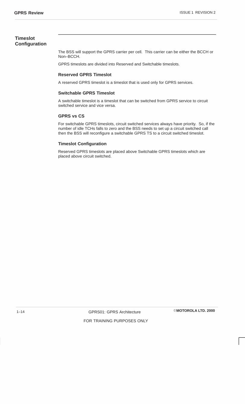
TimeslotConfiguration
The BSS will support the GPRS carrier per cell. This carrier can be either the BCCH orNon–BCCH.
GPRS timeslots are divided into Reserved and Switchable timeslots.
Reserved GPRS Timeslot
A reserved GPRS timeslot is a timeslot that is used only for GPRS services.
Switchable GPRS Timeslot
A switchable timeslot is a timeslot that can be switched from GPRS service to circuitswitched service and vice versa.
GPRS vs CS
For switchable GPRS timeslots, circuit switched services always have priority. So, if thenumber of idle TCHs falls to zero and the BSS needs to set up a circuit switched callthen the BSS will reconfigure a switchable GPRS TS to a circuit switched timeslot.
Timeslot Configuration
Reserved GPRS timeslots are placed above Switchable GPRS timeslots which areplaced above circuit switched.

ISSUE 1 REVISION 2 GPRS Review
�MOTOROLA LTD. 2000 GPRS01: GPRS Architecture
FOR TRAINING PURPOSES ONLY
1–15
Timeslot configuration
TCH
TCH
TCH
SW
SW
RES
RES
RES
TCH= Circuit switched TSSW= GPRS Switchable TSRES= GPRS Reserved TS
TS0
TS1
TS2
TS3
TS4
TS5
TS6
TS7

ISSUE 1 REVISION 2GPRS Review
�MOTOROLA LTD. 2000GPRS01: GPRS Architecture
FOR TRAINING PURPOSES ONLY
1–16
Packet TrafficChannels
One Packet Data Traffic Channel (PDTCH) is mapped to one physical channel. Up to 8PDTCH with different TS but some frequency parameters can be allocated to one MS atthe same time.
Packet Associated Control Channel (PACCH)
One Packet Associated Control Channel (PACCH) is mapped on to one physicalchannel. PACCH is dynamically allocated on a block basis. It provides signallinginformation including acknowledgements, power control and timing advance information.The PACCH can also be used for resource allocation messages, whilst the MS is alreadycarrying out packet transfer.
If a single PDTCH is assigned to an MS then the PACCH will be assigned on the samephysical channel. If multiple PDTCHs are assigned to a mobile then the PACCH isalways allocated on one of the Packet Data Channels (PDCHs) on which the PDTCHsare allocated.
PACCH is bi-directional in nature. In other words whilst the assignment might be uplinkor downlink, if PDTCHs are assigned on the uplink then one corresponding downlinktimeslot must be monitored for the possible occurrences of the PACCH. At the sametime, the MS can use the uplink assignment to send a PACCH at any time.
PDTCHs Dynamic Allocation
Dynamic Allocation allows multiple MSs to use the same uplink resource. This isaccomplished by using the Uplink State Flag (USF) , a 3 bit flag that can be used to allowup to 7 mobiles to access the same resource.
If, for example, a mobile is allocated in the assignment command timeslot 0, 2 and 3 thenthe mobile will monitor the downlink PDCH timeslots 0, 2 and 3 for its assigned USFvalue.
If the mobile receives the USF on a downlink block then on the next uplink block themobile will transmit and also on the next 3 blocks if USF granularity is set to 1.
UL PDTCH Fixed Allocation
Fixed Allocation uses the Packet Uplink Assignment to communicate a detailed fixeduplink resource allocation to the MS. This fixed allocation consists of a start frame, slotassignment and block assignment bitmap to represent the assigned blocks per timeslot.
PACCH the MS will transmit a ul PACCH at any time. To gain a dl PACCH the fixedallocation will purposely have gaps to allow the MS to monitor all PDCH for a PACCHaddressed to it. To this purpose the network will leave sets of 3 timeslot gaps in theuplink fixed allocation for the purpose of transmission of the dl PACCH.
During transfer of RLC/MAC blocks a mobile station may request to continue theTempoary Block Flow (TBF) by transmitting a Packet Resource Request on the ulPACCH. The network then responds with a Packet Resource Reassignment on the dlPACCH.

ISSUE 1 REVISION 2 GPRS Review
�MOTOROLA LTD. 2000 GPRS01: GPRS Architecture
FOR TRAINING PURPOSES ONLY
1–17
UL PDTCH Fixed Allocation
ÈÈÈÈÈÈÈÈÈÈÈÈ
ÈÈÈÈÈÈÈÈÈÈÈÈÈÈÈ
ÈÈÈÈÈÈÈÈÈÈÈÈÈÈÈ
ÈÈÈÈÈÈÈÈÈÈÈÈÈÈÈ
ÈÈÈÈÈÈÈÈÈÈÈÈÈÈÈ
ÈÈÈÈÈÈÈÈÈÈÈÈÈÈÈ
ÈÈÈÈÈÈÈÈÈÈÈÈ
ÈÈÈÈÈÈÈÈÈÈÈÈ
ÈÈÈÈÈÈÈÈÈÈÈÈ
ÈÈÈÈÈÈÈÈÈÈÈÈ
ÈÈÈÈÈÈÈÈÈÈÈÈ
ÈÈÈÈÈÈÈÈÈÈÈÈÈÈÈÈÈÈÈÈÈÈÈÈÈÈÈÈÈÈ
ÈÈÈÈÈÈÈÈÈÈÈÈÈÈÈÈÈÈÈÈÈÈÈÈÈÈÈÈÈÈ
TS0 TS1 TS2 TS3 TS4 TS5 TS6 TS7
B0 B1 B2 � B3 B4 B5 � B6 B7 B8 � B9 B10 B11 �
ÈÈÈÈÈÈÈÈÈÈÈÈÈÈÈ
B0 B1 B2 � B3 B4 B5 � B6 B7 B8 � B9 B10 B11 �
ÈÈÈÈÈÈÈÈÈÈÈÈ
= MS assigned blocks + timeslots

ISSUE 1 REVISION 2GPRS Review
�MOTOROLA LTD. 2000GPRS01: GPRS Architecture
FOR TRAINING PURPOSES ONLY
1–18
MS Classes withMultislotCapability
Phase 2+ Mobiles have the capability to use multiple slots in one TDMA frame in bothuplink and downlink. They are split into classes 1 through 29.
The mobiles are split into two types:
� Type 1 MS are not required to transmit and receive at the same time
� Type 2 MS are required to transmit and receive at the same time
Tt = Time to transmit.
Tr = Time to receive.
a = A measurement report is made
b = No measurement report made
a) = 1 with frequency hopping = 0 without frequency hoppingb) = 1 with frequency hopping or change from Rx to Tx = 0 without frequency hopping or no change from Rx to Txc) = 1 with frequency hopping or change from Tx to Rx = 0 without frequency hopping and no change from Tx to Rx
Type 1 MS are not required to transmit and receive at the same timeType 2 MS are required to be able to transmit and receive at the same time.

ISSUE 1 REVISION 2 GPRS Review
�MOTOROLA LTD. 2000 GPRS01: GPRS Architecture
FOR TRAINING PURPOSES ONLY
1–19
MS Classes with Multislot capabilitiesMultislot Maximum number of slots Minimum number of slots Type
Rx Tx Sum Tta Ttb Tra TrbDefault
1 1 1 2 3 2 4 2 1
2 2 1 3 3 2 3 1 1
3 2 2 3 3 2 3 1 1
4 3 1 4 3 1 3 1 1
5 2 2 4 3 1 3 1 1
6 3 2 4 3 1 3 1 1
7 3 3 4 3 1 3 1 1
8 4 1 5 3 1 2 1 1
9 3 2 5 3 1 2 1 1
10 4 2 5 3 1 2 1 1
11 4 3 5 3 1 2 1 1
12 4 4 5 2 1 2 1 1
13 3 3 NA NA a) 3 a) 2
14 4 4 NA NA a) 3 a) 2
15 5 5 NA NA a) 3 a) 2
16 6 6 NA NA a) 2 a) 2
17 7 7 NA NA a) 1 0 2
18 8 8 NA NA 0 0 0 2
19 6 2 NA 3 b) 2 c) 1
20 6 3 NA 3 b) 2 c) 1
21 6 4 NA 3 b) 2 c) 1
22 6 4 NA 2 b) 2 c) 1
23 6 6 NA 2 b) 2 c) 1
24 8 2 NA 3 b) 2 c) 1
25 8 3 NA 3 b) 2 c) 1
26 8 4 NA 3 b) 2 c) 1
27 8 4 NA 2 b) 2 c) 1
28 8 6 NA 2 b) 2 c) 1
29 8 8 NA 2 b) 2 c) 1

ISSUE 1 REVISION 2GPRS Review
�MOTOROLA LTD. 2000GPRS01: GPRS Architecture
FOR TRAINING PURPOSES ONLY
1–20
Fixed AllocationTimeslotAssignment
Fixed allocation presents particular restrictions to the allocation of Packet Data Channels(PDCHs) to multislot mobiles. In particular, the assignment must not conflict with therules for Packet Associated Control Channel (PACCH) monitoring or transmission andmeasurements of neighbour cells.
If for instance a multislot mobile station Class 4 is assigned a 3 timeslot Temporary BlockFlow (TBF) downlink and no uplink TBF. In this example the Packet DownlinkAssignment does not assign Measurement Mapping Parameters to the mobile so the MSmust make neighbour cell power measurement in 24 out of every 26 TDMA frames.
For multislot Class 4 mobiles the time needed for the MS to make a neighbour cell signalmeasurement and then get ready to transmit is 3 timeslots. Therefore the mobile canmake a measurement in every TDMA frame.
If the mobile is polled on timeslot 1, with a Relative Reserved Block Period (RRBP) ofzero (to send PACCH from next RLC/MAC Block on timeslot 1), then the mobile willtransmit a PACCH on timeslot 1. This transmission obeys the time needed for the mobileto transmit for multislot Class 4 which is 1 TS. It also conforms to the time needed tocarry out neighbour cell measurements.

ISSUE 1 REVISION 2 GPRS Review
�MOTOROLA LTD. 2000 GPRS01: GPRS Architecture
FOR TRAINING PURPOSES ONLY
1–21
Fixed Allocation Timeslot Assignment
ÉÉÉÉ
ÄÄÄÄÄÄÄÄ
ÉÉÉÉ
ÉÉÉÉ
ÄÄÄÄ
ÉÉÉÉÉÉÉÉ
ÉÉÉÉÉÉÉÉ
ÄÄÄÄ
ÉÉÉÉ
ÉÉÉÉÉÉÉÉ
ÄÄÄÄ
ÉÉÉÉ
ÉÉÉÉ
ÉÉÉÉÉÉÉÉ
ÉÉÉÉ
ÉÉÉÉ
ÉÉÉÉ
ÉÉÉÉÉÉÉÉ
ÉÉÉÉÉÉÉÉ
ÉÉÉÉ
ÉÉÉÉ
ÉÉÉÉ
ÉÉÉÉ
ÉÉÉÉÉÉÉÉ
ÉÉÉÉ
ÉÉÉÉÉÉÉÉ
ÉÉÉÉ
ÉÉÉÉ
ÉÉÉÉ
ÉÉÉÉÉÉÉÉ
ÉÉÉÉ
ÉÉÉÉÉÉÉÉ
ÉÉÉÉ
0 1 2 3 4 5 6 7
ÉÉÉÉÉÉÉÉ
ÉÉÉÉ
ÉÉÉÉ
ÉÉÉÉ0 1 2 3 4 5 6 7
RLC/MAC Block
poll
Downlink
Uplink
Ttb= 1 Tra= 3
Multislot class 4 (Rx= 3, Tx= 1, Sum= 4, 3 timeslot downlink TBF, with a poll on timeslot 1 (the natural timeslot)

ISSUE 1 REVISION 2GPRS Review
�MOTOROLA LTD. 2000GPRS01: GPRS Architecture
FOR TRAINING PURPOSES ONLY
1–22
MobilityManagement
Mobility Management (MM) activities are related to a GPRS subscriber and characterisedby 3 MM states. Each state describes a different level of functionality and informationallocated. These information sets are denoted by MM contexts at the SGSN and theMS.
Idle
In GPRS IDLE the subscriber is not attached to the GPRS Mobility Management. TheMS and SGSN context hold no location or routing information for the mobile. The GPRSMobile is seen as not reachable for PTP data transfers. PLMN selection and reselectionare performed by the MS.
Standby State (Stby)
In Stby state the subscriber is attached to the GPRS Mobility Management. The MS andthe SGSN have established MM contexts for the subscribers IMSI.
The subscriber may now receive pages for data transfers. Transmission and reception ofdata is not possible in this state.
� MS performs GPRS cell reselection and routing area
� MS updates SGSN if it enters a new RA
� MS may activate or deactivate PDP contexts
Ready State
The Ready state corresponds to the Stby state extended by location information for thesubscriber at call level. The MS performs MM procedures to notify the network with theactual selected cell. GPRS cell selection and reselection may be done by the MS, oroptionally controlled by the network.
An identifier of the cell is placed in the BSSGP header of the packet data from the MS.
The MS may send and receive PTP PDUs in this state. The network initiates no networkpages for an MS in the Ready State.
– MS may activate or deactivate PDP contexts
– MS may stay in the Ready State with or without Radio Resources allocated.

ISSUE 1 REVISION 2 GPRS Review
�MOTOROLA LTD. 2000 GPRS01: GPRS Architecture
FOR TRAINING PURPOSES ONLY
1–23
Idle/Stby/Ready
IDLE
READY
STANDBY
GPRS Attach
GPRS Detach
PDU transmission
READY timer expiryorForce to STANDBY
STANDBYtimer expiry
IDLE
READY
STANDBY
GPRS Attach
GPRS Detachor
Cancel Location
PDU reception
READY timerexpiryorForce toSTANDBYorAbnormal RLCcondition
MM State Model of MS MM State Model of SGSN
STANDBYtimer expiry
or cancellocation

ISSUE 1 REVISION 2GPRS Review
�MOTOROLA LTD. 2000GPRS01: GPRS Architecture
FOR TRAINING PURPOSES ONLY
1–24
Timing Advance
Packet Data Transmission is inherently ‘bursty’, by this the data transfer is notcontinuous. This presents problems with maintaining the correct timing advance for anMS during a data transfer.

ISSUE 1 REVISION 2 GPRS Review
�MOTOROLA LTD. 2000 GPRS01: GPRS Architecture
FOR TRAINING PURPOSES ONLY
1–25
Timing advance
Data Transmission

ISSUE 1 REVISION 2GPRS Review
�MOTOROLA LTD. 2000GPRS01: GPRS Architecture
FOR TRAINING PURPOSES ONLY
1–26
ContinuousTiming Advance
The initial timing advance is based on the single access burst carrying the PacketChannel Request. The estimated timing advance value is passed to the MS via thePacket Immediate Assignment. This value is used by the MS until continuous timingadvance update provides a new value.
In continuous timing advance the mobile sends in a special access burst in an idle slot forthe network to derive the timing advance. In the downlink the network sends a timingadvance value via the Packet Associated Control Channel (PACCH) which is transmittedduring the idle timeslots of the 52 multiframe.
Timing Advance Index gives the MS the position to send the access burst. For example,TAI = 1 refers to idle timeslot 2. The network will then update the MS timing advance inthe next Timing Advance Message and also the next 3 TA messages. The mobile onlyhas to read the message once.

ISSUE 1 REVISION 2 GPRS Review
�MOTOROLA LTD. 2000 GPRS01: GPRS Architecture
FOR TRAINING PURPOSES ONLY
1–27
Timing advance
B0 B1 B2 0 B3 B4 B5 1 B6 B7 B8 2 B9 B10 B11 3
52-multiframe number n:Uplink TAI=0 TAI=1
Downlink TA message 1
B0 B1 B2 4 B3 B4 B5 5 B6 B7 B8 6 B9 B10 B11 7
52-multiframe number n + 1:Uplink TAI=2 TAI=3
TAI message 1
Downlink TA message 1 TAI message 1
B0 B1 B2 8 B3 B4 B5 9 B6 B7 B8 10 B9 B10 B11 11
52-multiframe number n + 2:Uplink TAI=4 TAI=5
Downlink TA message 2 TAI= message 2
B0 B1 B2 12 B3 B4 B5 13 B6 B7 B8 14 B9 B10 B11 15
52-multiframe number n + 3:Uplink TAI=6 TAI=7
Downlink TA message 2 TAI= message 2
B0 B1 B2 16 B3 B4 B5 17 B6 B7 B8 18 B9 B10 B11 19
52-multiframe number n + 4:Uplink TAI=8 TAI=9
Downlink TA message 3
B0 B1 B2 20 B3 B4 B5 21 B6 B7 B8 22 B9 B10 B11 23
52-multiframe number n + 5:Uplink TAI=10 TAI=11
TAI message 3
Downlink TA message 3 TAI message 3
B0 B1 B2 24 B3 B4 B5 25 B6 B7 B8 26 B9 B10 B11 27
52-multiframe number n + 6:Uplink TAI=12 TAI=13
Downlink TA message 4 TAI= message 4
B0 B1 B2 28 B3 B4 B5 29 B6 B7 B8 30 B9 B10 B11 31
52-multiframe number n + 7:Uplink TAI=14 TAI=15
Downlink TA message 4 TAI= message 4
B0 – B11= Radio blocks idle bursts are numbered from 0 to 31

ISSUE 1 REVISION 2GPRS Review
�MOTOROLA LTD. 2000GPRS01: GPRS Architecture
FOR TRAINING PURPOSES ONLY
1–28
MobileOriginatedPacket Transfer
On entry into a cell, the mobile will read System Information Messages 3,4,7 or 8. Thecell, if it supports GPRS, will transmit System Information message 13 and optionally 14and 15.
The MS initiates the Packet Access Procedure by the sending of a Channel Requestmessage on the RACH. The RSS forwards the RACH to the Pack Control Unit (PCU).The PCU then generates the Immediate Assignment allocating a Packet Data Channel(PDCH) from its pool of resources.
The MS now sends on the PDCH a Packet Resource Request requesting FixedAllocation , which will indicate the priority of the data, the number of octets of data theMS uses to transfer and the requested bandwidth, e.g. 500 Kbps.
The PCU will respond with the Packet Resource Assignment on the Packet AssociatedControl Channel (PACCH). This message assigns timeslots to the mobile and theallocated blocks to transmit on. Also within the message will be the Temporary FlowIndentifier (TFI) to identify the Temporary Block Flow (TBF) for transmitting the airinterface.
TFI Temporary Flow Indentifier
TBF Temporary Block Flow

ISSUE 1 REVISION 2 GPRS Review
�MOTOROLA LTD. 2000 GPRS01: GPRS Architecture
FOR TRAINING PURPOSES ONLY
1–29
Mobile Originated Packet Transfer (No PBCCH)
PCU RSS MS
SYSTEM INFORMATION BCCH
PACKET CHANNEL REQUEST RACH
GSL TO RSL
PACKET IMMEDIATE ASSIGNMENT AGCH
PACKET RESOURCE REQUEST PACCH
PACKET RESOURCE ASSIGNMENT PACCH
DATA BLOCK PDTCH
DATA BLOCK PDTCH
SYSTEM INFORMATION

ISSUE 1 REVISION 2GPRS Review
�MOTOROLA LTD. 2000GPRS01: GPRS Architecture
FOR TRAINING PURPOSES ONLY
1–30
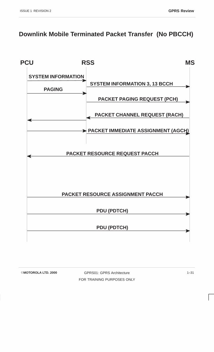
Downlink MobileTerminatedPacket Transfer
As before, on entry to the cell the mobile will read system information messages on theBCCH. If GPRS is present in the cell then the system information messages will indicatethis and also the presence of system information message 13. The Information message13 gives the information of power control, priority access, classes allowed. Informationmessage 14 gives information of reference frequency lists and mobile allocationsapplicable to packet access in a cell. Information message 15 gives information onpacket power control interference measurements.
If the mobile is in the Standby state then the network may page the mobile to transferPDUs. Paging sent from the SGSN will be handled by the Packet Control Unit (PCU)and dependent on the state of the mobile will result in paging by routing area or in a cell.
The mobile will respond with an RACH with a cause value indicating GPRS. The RSSwill pass this channel request to the PCU which will allocate a PDCH for 2 phase access.This is sent to the mobile on the AGCH.
The set up is now as before as mobile originated Packet Transfer.
ISSUE 1 REVISION 2 GPRS Review
�MOTOROLA LTD. 2000 GPRS01: GPRS Architecture
FOR TRAINING PURPOSES ONLY
1–31
Downlink Mobile Terminated Packet Transfer (No PBCCH)
PCU RSS MS
SYSTEM INFORMATION 3, 13 BCCH
PACKET PAGING REQUEST (PCH)
PACKET RESOURCE REQUEST PACCH
PACKET RESOURCE ASSIGNMENT PACCH
PDU (PDTCH)
PDU (PDTCH)
SYSTEM INFORMATION
PAGING
PACKET CHANNEL REQUEST (RACH)
PACKET IMMEDIATE ASSIGNMENT (AGCH)

ISSUE 1 REVISION 2GPRS Review
�MOTOROLA LTD. 2000GPRS01: GPRS Architecture
FOR TRAINING PURPOSES ONLY
1–32
Uplink PacketTransfer
Once the Access and Assignment is complete, the mobile awaits its allocated blocks onthe allocated Packet Data Channels (PDCHs). Once the allocated blocks arrive the MSshall begin to transmit Radio Link Control (RLC) data blocks on its Packet Data TrafficChannels (PDTCHs).
These RLC data blocks are all uniquely identified by the Temporary Flow Indentifier (TFI).The unique identification on the TFI is included in every RLC data or control block relatedto the Temporary Block Flow (TBF). Because each radio block contains an identifier(TFI) all received blocks are correctly associated a particular LLC frame and a particularMS.
The network will acknowledge transfers by sending Packet Uplink ACK/NACK messageson the Packet Associated Control Channel (PACCH) during gaps in the uplink allocation.The message contains the status of the received RLC data blocks. The message mayalso update the timing advance, power control parameters and assign uplink resources toa fixed mobile.
The mobile will continue transmitting the RLC data blocks, retransmitting those datablocks indicated by the network until it reaches its last RLC data block.

ISSUE 1 REVISION 2 GPRS Review
�MOTOROLA LTD. 2000 GPRS01: GPRS Architecture
FOR TRAINING PURPOSES ONLY
1–33
Uplink Packet Transfer
MSNetwork
DATA BLOCK
ACCESS AND ASSIGNMENT
DATA BLOCK
DATA BLOCK
DATA BLOCK
TEMP ACK/NACK
DATA BLOCK
DATA BLOCK
DATA BLOCK
DATA BLOCK
DATA BLOCK
DATA BLOCK
DATA BLOCK
DATA BLOCK
TEMP ACK/NACK
DATA BLOCK
DATA BLOCK (LAST)
FINAL PACKET ACK//NACK
PACKET RESOURCE ASSIGNMENT

ISSUE 1 REVISION 2GPRS Review
�MOTOROLA LTD. 2000GPRS01: GPRS Architecture
FOR TRAINING PURPOSES ONLY
1–34
MobileTerminatedPacket Transfer
As before with Mobile Originate Packet Transfer the network assigns a unique TemporaryFlow Identifier (TFI) with regards to the downlink Temproary Block Flow (TBF) and a setof Packet Data Channels (PDCHs) to be used for the downlink transfer and a TBF statingtime (optional ).
The MS on reception of the downlink assignment will either attempt to decode everydownlink block on its assigned PDCHs or it is sent on TBF starting time, wait on theCCCH until the TDMA framenumber indicated by the TBF starting time.
When the mobile receives an Radio Link Control (RLC) data block addressed to itself andwith a polling indication in the uplink radio block specified in the header, then the mobilewill transmit an ACK/NACK or control message (mobile will only transmit a RLC/MACcontrol message instead of ACK/NACK, at most, every fourth time it is polled).
The network initiates a release of a downlink TBF by sending an RLC data block with theFinal Bit Indicator (FBI) and a valid polling indication. The mobile shall transmit a PacketACK/NACK in the uplink radio block specified.

ISSUE 1 REVISION 2 GPRS Review
�MOTOROLA LTD. 2000 GPRS01: GPRS Architecture
FOR TRAINING PURPOSES ONLY
1–35
Mobile terminated packet transfer
PCU MS
ACCESS AND ASSIGNMENT
FINAL PACKET ACK/NACK PACCH
DATA BLOCK PDTCH
DATA BLOCK (POLLING) PDTCH
TEMP PACKET ACK/NACK PACCH
DATA BLOCK PDTCH
DATA BLOCK (LAST/POLLING)

ISSUE 1 REVISION 2GPRS Review
�MOTOROLA LTD. 2000GPRS01: GPRS Architecture
FOR TRAINING PURPOSES ONLY
1–36
Radio LinkControl (RLC)
The Radio Link Control (RLC) function is responsible for:
� Interface allowing transfer of UC PDUs between the Logical Link Control (LLC)Layer and the Media Access Control (MAC) function
� Segmentation of LLC PDUs into RLC data blocks and re-assembly of RLC datablocks into LLC PDUs
� Backwards Error Correction (BEC) Procedures enabling selective retransmissionof RLC data blocks
An RLC connection comprises two peer entities. Each RLC endpoint has a receiver thatreceives RLC data blocks. Each RLC endpoint has a transmitter that transmits RLC datablocks.

ISSUE 1 REVISION 2 GPRS Review
�MOTOROLA LTD. 2000 GPRS01: GPRS Architecture
FOR TRAINING PURPOSES ONLY
1–37
Radio link control (RLC)
RLC
MAC
PhysicalLayer
LLC
RLC
MAC
PhysicalLayer
LLC
RLC
MAC
PhysicalLayer
FH FCSINFORMATION FIELD
BH INFO FIELD BCS BH INFO FIELD BCS BH INFO FIELD BCS
NORMALBURST
NORMALBURST
NORMALBURST
NORMALBURST
LLC
RLC/MAC
PHYSICALLAYER

ISSUE 1 REVISION 2GPRS Review
�MOTOROLA LTD. 2000GPRS01: GPRS Architecture
FOR TRAINING PURPOSES ONLY
1–38
RLC DataACK/NACK
The Radio Link Control (RLC) peers each have a receive and transmit window of 0 –127. The window size is 64 blocks. The sending side can transmit blocks within awindow of 64 blocks and the receiving side periodically sends temporary ACK/NACKmessages. Every such message acknowledges all correctly received blocks and canrequest erroneously received RLC data blocks for retransmission.
Each RLC data block contains a block sequence number (BSN) in the range 0 – 127. Inthe send side a variable V(s) denotes the next in sequence RLC data block to be sent, onthe receive side a variable V(R) denotes the next in sequence RLC block to be received.
Acknowledge state variables, the send side has an acknowledge variable V(a) thatcontains the BSN of the oldest RLC block that has not been acknowledged. On theReceive side the variable V(Q) denotes the oldest RLC data block that has not beenreceived.
The send side maintains an Acknowledge state array V(B), an array of 128 elementsindicating the acknowledgement status of transmitted RLC data blocks that are eitherpending – ACK or NACKED or INVALID.
The order of transmitted RLC blocks is the oldest RLC block that has been NACKED. Ifthe sliding window is still open, i.e. V(S) <V(A) +K then the next RLC data block withBSN = V(S) shall be transmitted and the V(B) array element set to PENDING – ACK.
Once the V(S) = V(A) + K, in other words the window is stalled. Then the send side shalltransmit the oldest element in V(B) that has the value PENDING – ACK.

ISSUE 1 REVISION 2 GPRS Review
�MOTOROLA LTD. 2000 GPRS01: GPRS Architecture
FOR TRAINING PURPOSES ONLY
1–39
Radio Link Control (RLC) data Ack/Nack
MS PCU
BSN= 2
RLC BLOCK BSN= 0
RLC BLOCK BSN= 1
ACK 0, 1 NACK 2
RLC BLOCK BSN= 2
BSN= 3
BSN= 65
BSN= 2
BSN= 3
ACK 2 – 65
BSN= 66
Va= 0
Va= 2
Stalled
Vq= 2

ISSUE 1 REVISION 2GPRS Review
�MOTOROLA LTD. 2000GPRS01: GPRS Architecture
FOR TRAINING PURPOSES ONLY
1–40
Release of Uplink
Temporary Block Flow (TBF)
The mobile station sends in the Radio Link Control (RLC) data block a Countdown Value(CV) to indicate to the network the last RLC data block that will be sent in the uplink TBF.The CV is calculated as a value dependant on the number of Timeslots assigned on theuplink and the total number of RLC data blocks in the TBF and a broadcast parameterBS – CV – MAX.
BS – CV – MAX is the number of blocks the countdown will begin before the last block istransmitted. For example, as BS – CV – MAX of 4 would mean that the last 4 blocks willcount down to 0. A CV of 15 is the norm value for RLC data blocks.

ISSUE 1 REVISION 2 GPRS Review
�MOTOROLA LTD. 2000 GPRS01: GPRS Architecture
FOR TRAINING PURPOSES ONLY
1–41
Release of uplink
15 3 2 1 0
BS_CV_MAX= 4
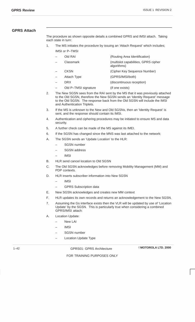
ISSUE 1 REVISION 2GPRS Review
�MOTOROLA LTD. 2000GPRS01: GPRS Architecture
FOR TRAINING PURPOSES ONLY
1–42
GPRS Attach
The procedure as shown opposite details a combined GPRS and IMSI attach. Takingeach state in turn:
1. The MS initiates the procedure by issuing an ‘Attach Request’ which includes;
IMSI or P–TMSI
– Old RAI (Routing Area Identification)
– Classmark (multislot capabilities, GPRS cipher algorithms)
– CKSN (Cipher Key Sequence Number)
– Attach Type (GPRS/IMSI/both)
– DRX (discontinuous reception)
– Old P–TMSI signature (if one exists)
2. The New SGSN sees from the RAI sent by the MS that it was previously attachedto the Old SGSN, therefore the New SGSN sends an ‘Identity Request’ messageto the Old SGSN. The response back from the Old SGSN will include the IMSIand Authentication Triplets.
3. If the MS is unknown to the New and Old SGSNs, then an ‘Identity Request’ issent, and the response should contain its IMSI.
4. Authentication and ciphering procedures may be initiated to ensure MS and datasecurity.
5. A further check can be made of the MS against its IMEI.
6. If the SGSN has changed since the MNS was last attached to the network:
A. The SGSN sends an ‘Update Location’ to the HLR:
– SGSN number
– SGSN address
– IMSI
B. HLR send cancel location to Old SGSN
C. The Old SGSN acknowledges before removing Mobility Management (MM) andPDP contexts.
D. HLR inserts subscriber information into New SGSN
– IMSI
– GPRS Subscription data
E. New SGSN acknowledges and creates new MM context
F. HLR updates its own records and returns an acknowledgement to the New SGSN.
7. Assuming the Gs interface exists then the VLR will be updated by use of ‘LocationUpdate’ by the SGSN. This is particularly true when considering a combinedGPRS/IMSI attach:
A. Location Update:
– New LAI
– IMSI
– SGSN number
– Location Update Type

ISSUE 1 REVISION 2 GPRS Review
�MOTOROLA LTD. 2000 GPRS01: GPRS Architecture
FOR TRAINING PURPOSES ONLY
1–43
Attach
MS BSSNEWSGSN
OLDSGSN GGSN EIR
NEWMSC/VLR HLR
OLDMSC/VLR
1. Attach Request
2. Identification Request
2. Identification Response
3. Identity Request
3. Identity Response
4. Authentication
5. IMEI Check
6a. Update Location
6b. Cancel Location
6c. Cancel Location Ack
6d. Insert Subscriber Data
6e. Insert Subscriber Data Ack
6f. Update Location Ack
7a. Location Updating Request
7b. Update Location
7c. Cancel Loc Ack
7d. Cancel Loc Ack
7e. Insert Subscriber Data
7f. Insert Subscriber Data
7g. Update Location Ack
7h. Location Updating Accept
8. Attach Accept
9. Attach Complete
10. TMSI Reallocation Complete

ISSUE 1 REVISION 2GPRS Review
�MOTOROLA LTD. 2000GPRS01: GPRS Architecture
FOR TRAINING PURPOSES ONLY
1–44
B. New VLR indicates to HLR of a location update
HLR takes over and cancels the location in the Old VLR (c and D), before insertingnew subscriber information in the New VLR (e). Finally the HLR acknowledges tothe New VLR.
C. The New VLR acknowledges the ‘Location Update’ back to the SGSN.
8. The SGSN sends an ‘Attach Accept’ to the MS containing:
– P–TMSI
– VLR TMSI
9. If the P–TMSI or VLR TMSI have been changed by the SGSN then the MS needsto acknowledge.
10. If the VLR TMSI has been changed and acknowledged by the MS, then the SGSNneeds to acknowledge back to the VLR.

ISSUE 1 REVISION 2 GPRS Review
�MOTOROLA LTD. 2000 GPRS01: GPRS Architecture
FOR TRAINING PURPOSES ONLY
1–45
Attach
MS BSSNEWSGSN
OLDSGSN GGSN EIR
NEWMSC/VLR HLR
OLDMSC/VLR
1. Attach Request
2. Identification Request
2. Identification Response
3. Identity Request
3. Identity Response
4. Authentication
5. IMEI Check
6a. Update Location
6b. Cancel Location
6c. Cancel Location Ack
6d. Insert Subscriber Data
6e. Insert Subscriber Data Ack
6f. Update Location Ack
7a. Location Updating Request
7b. Update Location
7c. Cancel Loc Ack
7d. Cancel Loc Ack
7e. Insert Subscriber Data
7f. Insert Subscriber Data
7g. Update Location Ack
7h. Location Updating Accept
8. Attach Accept
9. Attach Complete
10. TMSI Reallocation Complete

ISSUE 1 REVISION 2GPRS Review
�MOTOROLA LTD. 2000GPRS01: GPRS Architecture
FOR TRAINING PURPOSES ONLY
1–46
GPRS Detach
With respect to the diagrams shown opposite we should consider the three defineddetach procedures.
The top diagram on the opposite page details the Detach procedure that is initiated bythe MS.
1. The MS initiates by sending Detach Request
– Detach Type
– Switch Off (switch off or not)
2. If GPRS detach then the PDP context needs to be deleted in the GGSN
3. If IMSI detach, the SGSN sends IMSI detach to the VLR
4. If the MS wishes to remain IMSI attached and remove its GPRS context in theVLR
5. If the switch off parameter indicated that the MS was being switched off, then the‘Detach Accept’ is not sent.
If the detach is initiated by the SGSN, then the sequence is similar to that above, exceptthat the initial message detailed in 1 above is started by the SGSN. Stages 2 and 4above are used as shown in the middle diagram on the opposite page.
The detach sequence could be started by the HLR as shown in bottom diagram on theoppsite page, by the use of a ‘Cancel Location’ MAP message. Following the ‘CancelLocation’ message, the procedure is much the same as for the SGSN initiated detachprocedure.

ISSUE 1 REVISION 2 GPRS Review
�MOTOROLA LTD. 2000 GPRS01: GPRS Architecture
FOR TRAINING PURPOSES ONLY
1–47
Detach
MS BSS SGSN GGSN MSC/VLR
1. Detach Request2. Delete PDP Context Request
2. Delete PDP Context Response
3. IMSI Detach Indication
4. GPRS Detach Indication5. Detach Accept
MS BSS SGSN GGSN MSC/VLR
1. Detach Request2. Delete PDP Context Request
2. Delete PDP Context Response
3. GPRS Detach Indication4. Detach Accept
MS BSS SGSN GGSN MSC/VLR
3. Delete PDP Context Request
4. GPRS Detach Indication
1. Cancel Location2. Detach Request
3. Delete PDP Context Response
5. Detach Request
6. Cancel Location Ack
HLR
HLR
HLR

ISSUE 1 REVISION 2GPRS Review
�MOTOROLA LTD. 2000GPRS01: GPRS Architecture
FOR TRAINING PURPOSES ONLY
1–48
Paging for GPRSDownlinkTransfer
An MS has to be paged by the SGSN before a downlink transfer can occur. The pagingprocess is shown opposite and detailed below:
1. SGSN receives Protocol Data Units (PDUs) for an MS from the network and pagesthe MS.
2. The SGSN sends a BSSGP Paging Request:
– IMSI
– P–TMSI
– Area (Routing Area)
– Channel Needed (indicates GPRS paging)
– QoS (Quality of Service)
– DRX
3. The BSS pages the MS with:
– P–TMSI
– Channel Needed
4. The MS shall respond by use of a Receive Ready or Information frame
5. The BSS, upon receipt of the Logical Link Control (LLC) frame, adds an identifierof the cell and sends the complete LLC frame to the SGSN.

ISSUE 1 REVISION 2 GPRS Review
�MOTOROLA LTD. 2000 GPRS01: GPRS Architecture
FOR TRAINING PURPOSES ONLY
1–49
GPRS Paging Area
MS BSS SGSN
1. PDP PDU
2. Paging Request
3. GPRS Page Request
4. Any LLC Frame
5. Any LLC Frame

ISSUE 1 REVISION 2GPRS Review
�MOTOROLA LTD. 2000GPRS01: GPRS Architecture
FOR TRAINING PURPOSES ONLY
1–50
PDP ContextActivation
PDP Context Activation is shown in the diagram oppsite and follows the sequence shownhere:
1. The MS sends an ‘Activate PDP Context Request’ containing:
– NSAPI
– PDP type
– PDP Address (leaves blank to request dynamic address)
– Access Point Name (reference point to external network, viaDNS)
– QoS Requested
– PDP Configuration Options
2. Security Functions may be executed
3. The SGSN then determines the GGSN to address via a combination of:
– IMSI + NSAPI (= TID)
– (GGSN will allocate dynamic PDP Address if left blank above)
‘Create PDP Context Request’ containing:
– PDP Type
– PDP Address
– Access Point Name
– QoS Negotiated
– TID
– Selection Mode (subscribed or non–subscribed APN)
– PDP Configuration Options
‘Create PDP Context Response’ containing:
– TID
– PDP Address
– BB Protocol (TCP or UDP over Gn)
– Reordering Required (reorder of N–PDUs from GGSN before delivery)
– PDP configuration options
– QoS Negotiated
– Cause
4. The SGSN inserts the NSAPI along with the GGSN address in its PDP context. Ifthe MS requested a dynamic address then it is inserted into the SGSNs PDPcontext. SGSN returns:
– PDP Type
– PDP Address
– NSAPI
– QoS Negotiated
– Radio Priority Level
– PDP Configuration Options
The SGSN is now able to route PDUs between the GGSN and MS.
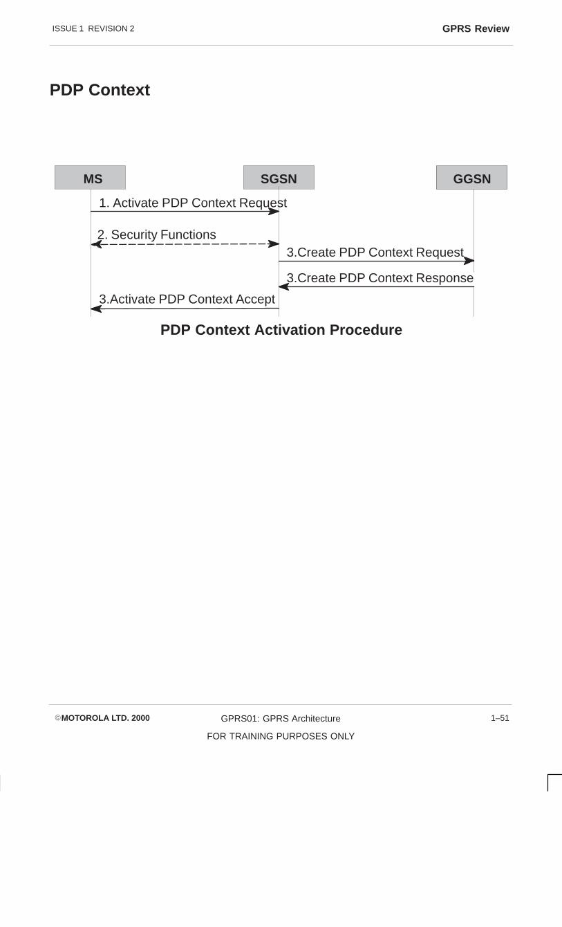
ISSUE 1 REVISION 2 GPRS Review
�MOTOROLA LTD. 2000 GPRS01: GPRS Architecture
FOR TRAINING PURPOSES ONLY
1–51
PDP Context
MS SGSN GGSN
1. Activate PDP Context Request
2. Security Functions3.Create PDP Context Request
3.Create PDP Context Response
3.Activate PDP Context Accept
PDP Context Activation Procedure

ISSUE 1 REVISION 2GPRS Review
�MOTOROLA LTD. 2000GPRS01: GPRS Architecture
FOR TRAINING PURPOSES ONLY
1–52
In the diagram opposite the network is requesting PDP context activation. In thisinstance the GGSN has received PDP PDUs from an external network and because noPDP context has been previously established then the network has to start thesequence.
The network may employ techniques such as:
Mobile station Not Reachable for GPRS flag (MNRG), the SGSN, GGSN and HLR,which will prevent the GGSN from trying to contact the mobile when it is switched offor out of coverage area.
The GGSN may decide to discard future PDP PDUs as a result of previousunsuccessful delivery attempts.
The GGSN may store the address of the SGSN for a particular PDP context and soeliminate the need for communicating with the HLR.
1. The GGSN has received PDP PDU for an MS and has decided to initiate theNetwork–Requested PDP Context Activation procedure.
2. The GGSN may need to request routing information from the HLR for a mobile it isunaware of the supporting SGSN. The response from the HLR would include:
IMSISGSN AddressMobile State Not Reachable Reason (containing MNRG flag)
3. GGSN sends a ‘PDU Notification Request’ containing:
IMSIPDP TypePDP Address
With the SGSN responding to the request to indicate that it will communicate with theMS.
4. The SGSN sends a ‘Request PDP Context Activation’ containing:
PDP TypePDP Address
5. The PDP context activation procedure detailed earlier is now used to complete theprocess, before PDUs can be transported.

ISSUE 1 REVISION 2 GPRS Review
�MOTOROLA LTD. 2000 GPRS01: GPRS Architecture
FOR TRAINING PURPOSES ONLY
1–53
PDP Context
MS SGSN HLR
Successful Network-requested PDP Context Activation Procedure
GGSN
1. PDP PDU
3.PDU Notfication Request
2. Send Routeing Info for GPRS Ack
2. Send Routeing Info for GPRS
3.PDU Notfication Response
4.Request PDP Context Activation
5. PDP Context Activation Procedure

ISSUE 1 REVISION 2GPRS Review
�MOTOROLA LTD. 2000GPRS01: GPRS Architecture
FOR TRAINING PURPOSES ONLY
1–54
PDP ContextModificationProcedure
In the upper diagram opposite the PDP context can be modified by the procedure shown.This would be requested in particular instances, e.g. change of Quality of Service (QoS)parameters, possibly because the GGSN was unable to provide the full range ofparameters. Thus:
1. The SGSN could request an ‘Update PDP Context Request’
TIDQos Negotiated
2. The GGSN will return with:
TIDQoS Negotiated
3. The SGSN sends a ‘Modify PDP Context’
NSAPIQoS NegotiatedRadio Priority Level
4. The MS should acknowledge the new parameters before they take effect.
PDP ContextDeactivation
The next diagrams detail how the PDP context may be deactivated
PDP Context Deactivation Initiated by MS Procedure:
1. MS sends a ‘Deactivate PDP Context Request’ containing the NSAPI to theSGSN.
2. Security Functions (optional)
3. The SGSN sends a ‘Delete PDP Context Request’ containing TID. GGSNremoves PDP context and sends a valid response.
4. The SGSN sends a ‘response’ to the MS containing the NSAPI.
PDP ContextDeactivationInitiated byGGSN Procedure
1. The GGSN sends a ‘ Delete PDP Context Request’ containing the TID.
2. The SGSN sends a ‘Deactivate PDP Context’ message together with the NSAPI tothe MS, which deletes the PDP context and responds with the same NSAPI to theSGSN.
3. The SGSN then responds with the TID to the GGSN. If the PDP Address wasdynamic, then the GGSN releases the PDP Address for use by a subsequentactivation.

ISSUE 1 REVISION 2 GPRS Review
�MOTOROLA LTD. 2000 GPRS01: GPRS Architecture
FOR TRAINING PURPOSES ONLY
1–55
Altering PDP Context
MS GGSN
4. Modify PDP Context Accept
1.Update PDP Context Request
2.Update PDP Context Response
3. Modify PDP Context Request
PDP Context Modification Procedure
SGSN
MS GGSN
3. Delete PDP Context Request
PDP Context Deactivation Initiated by MS Procedure
SGSN
MS GGSN
1. Delete PDP Context Request
3. Delete PDP Context Accept
PDP Context Deactivation Initiated by GGSN
SGSN
2. Security Functions
3. Delete PDP Context Response
1. Deactivate PDP Context Request
4. Deactivate PDP Context Accept
2. Deactivate PDP Context Accept
2. Deactivate PDP Context Request
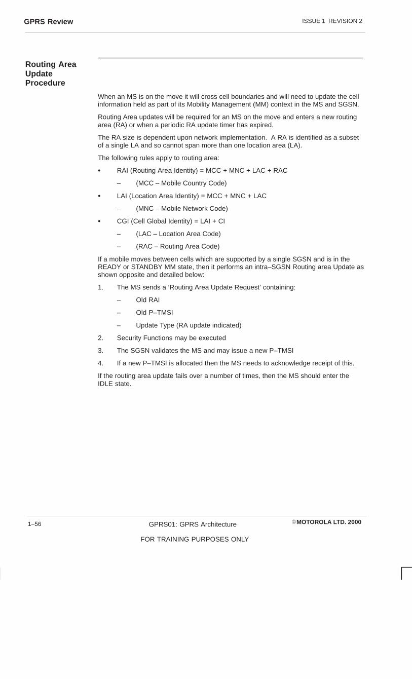
ISSUE 1 REVISION 2GPRS Review
�MOTOROLA LTD. 2000GPRS01: GPRS Architecture
FOR TRAINING PURPOSES ONLY
1–56
Routing AreaUpdateProcedure
When an MS is on the move it will cross cell boundaries and will need to update the cellinformation held as part of its Mobility Management (MM) context in the MS and SGSN.
Routing Area updates will be required for an MS on the move and enters a new routingarea (RA) or when a periodic RA update timer has expired.
The RA size is dependent upon network implementation. A RA is identified as a subsetof a single LA and so cannot span more than one location area (LA).
The following rules apply to routing area:
� RAI (Routing Area Identity) = MCC + MNC + LAC + RAC
– (MCC – Mobile Country Code)
� LAI (Location Area Identity) = MCC + MNC + LAC
– (MNC – Mobile Network Code)
� CGI (Cell Global Identity) = LAI + CI
– (LAC – Location Area Code)
– (RAC – Routing Area Code)
If a mobile moves between cells which are supported by a single SGSN and is in theREADY or STANDBY MM state, then it performs an intra–SGSN Routing area Update asshown opposite and detailed below:
1. The MS sends a ‘Routing Area Update Request’ containing:
– Old RAI
– Old P–TMSI
– Update Type (RA update indicated)
2. Security Functions may be executed
3. The SGSN validates the MS and may issue a new P–TMSI
4. If a new P–TMSI is allocated then the MS needs to acknowledge receipt of this.
If the routing area update fails over a number of times, then the MS should enter theIDLE state.

ISSUE 1 REVISION 2 GPRS Review
�MOTOROLA LTD. 2000 GPRS01: GPRS Architecture
FOR TRAINING PURPOSES ONLY
1–57
MS BSS SGSN
2. Security Functions
3. Routeing Area Update Accepts
4. Routeing Area Update Acknowledge
1. Routeing Area Update Request

ISSUE 1 REVISION 2GPRS Review
�MOTOROLA LTD. 2000GPRS01: GPRS Architecture
FOR TRAINING PURPOSES ONLY
1–58
Combined RA/LAUpdate in thecase of InterSGSN RA UpdateProcedure
If the moving MS crosses cell/Routing Area (RA) boundaries which are supported bydifferent SGSNs, then an Inter SGSN RA Update should be performed.
There may be a need to update the Routing Area (RA) and additionally the LA may needto be updated for the IMSI attached mobile. To prevent excess messages to theVLR/HLR, then the LA update can be combined into the GPRS RA update.
A combined RA/LA update is shown opposite and detailed below:
1. The MS sends a ‘Routing Area Update Request’ containing:
– Old RAI
– Old P–TMSI Signature (allocated by SGSN)
– Update Type
The BSS shall add an identifier of the cell where the message was received beforepassing the message to the SGSN.
2. The New SGSN shall be able to determine the Old SGSN from the old RoutingArea identity (RAI) and the new RAI and Location Area Identity (LAI) from the cellidentifier added by the BSS.
The new SGSN context request to the Old SGSN containing:
– Old RAI
– Temporary Logical Link Identity (TLLI)
– Old P–TMSI Signature
– New SGSN Address
In order to get the MM and PDP contexts for the MS.
The Old SGSN responds with:
– MM Context
– PDP Contexts
– LLC Acknowledge
The Old SGSN stores the New SGSN Address until the old MM context is cancelled toallow the Old SGSN to forward data packets to the new SGSN. The Old SGSN starts atimer.
3. Security Functions. Optional
4. New SGSN sends ‘SGSN Context Acknowledge’ to Old SGSN.
5. The Old SGSN starts tunnelling of buffered N–PDUs to the New SGSN. AdditionalN–PDUs received from the GGSN before timer in 2) above expires is alsotunneled.
6. The New SGSN sends ‘Update PDP Context’ to GGSN:
– New SGSN Address, TID and Negotiated Quality of Service (QoS).
– GGSN responds with TID.

ISSUE 1 REVISION 2 GPRS Review
�MOTOROLA LTD. 2000 GPRS01: GPRS Architecture
FOR TRAINING PURPOSES ONLY
1–59
Combined RA/LA Update
MS BSSNEWSGSN
OLDSGSN GGSN
NEWMSC/VLR HLR
OLDMSC/VLR
1. Routing Area Update request
2. SGSN Context Request
2. SGSN Context Response
3. Security Functions
4. SGSN context Acknowledge
5. Forward packets
6. Update PDP Context Request
7. Update location
12a. Update Location
12d. Insert Subscriber Data
12e. Insert Subscriber Data Ack
14 Routing Area Update Accept
15. Routing Area Update Complete
16. TMSI Reallocation Complete
6. Update PDP Context Response
8. Cancel Location
8. Cancel Location Ack
9. Insert Subscriber Data
9. Insert Subscriber Data Ack
10. Update Location Ack
11. Location Updating Request
12b. Cancel Location
12c Cancel Location Ack
12f. Update Location Ack
13. Location Updating Accept

ISSUE 1 REVISION 2GPRS Review
�MOTOROLA LTD. 2000GPRS01: GPRS Architecture
FOR TRAINING PURPOSES ONLY
1–60
7. The New SGSN informs the HLR of the change of SGSN by sending ‘UpdateLocation’:
– SGSN Number
– SGSN Address
– IMSI
8. HLR sends a ‘Cancel Location’ to the Old SGSN in order to remove the MM andPDP contexts.
9. The HLR ‘Inserts Subscriber Data’ into the New SGSN:
– IMSI
– GPRS Subscription Data
10. The HLR acknowledges the ‘Update Location’ with IMSI to New SGSN.
11. The New SGSN ‘Location Update Request’ to the VLR to update the LA,containing:
– New LAI
– IMSI
– SGSN Number
– Location Update Type
12. If the Location Update is Inter–MSC the New VLR informs the HLR. The HLRcancels the old location and inserts the new data into the New VLR.
13. If the location update is successful the new VLR allocates a new TMSI to theSGSN.
14. The New SGSN establishes MM and PDP contexts for the MS and responds tothe MS with:
– P–TMSI
– VLR TMSI
– LLC Acknowledge
– P–TMSI Signature
15. MS confirms allocation of TMSI and P–TMSI and LLC acknowledge.
16. The New SGSN sends TMSI reallocation complete message to VLR.

�MOTOROLA LTD. 2000 GPRS01: GPRS Architecture
FOR TRAINING PURPOSES ONLY
i
Chapter 2
PCU Architecture

ISSUE 1 REVISION 2
�MOTOROLA LTD. 2000GPRS01: GPRS Architecture
FOR TRAINING PURPOSES ONLY
ii

ISSUE 1 REVISION 2
�MOTOROLA LTD. 2000 GPRS01: GPRS Architecture
FOR TRAINING PURPOSES ONLY
iii
Chapter 2PCU Architecture i. . . . . . . . . . . . . . . . . . . . . . . . . . . . . . . . . . . . . . . . . . . . . . . . . . .
Objectives 2–1. . . . . . . . . . . . . . . . . . . . . . . . . . . . . . . . . . . . . . . . . . . . . . . . . . . . . . . . . . . . . . . . .
Packet Control Unit (PCU) 2–2. . . . . . . . . . . . . . . . . . . . . . . . . . . . . . . . . . . . . . . . . . . . . . . . . . . The GPRS solution 2–4. . . . . . . . . . . . . . . . . . . . . . . . . . . . . . . . . . . . . . . . . . . . . . . . . . . .
Device Equipage 2–6. . . . . . . . . . . . . . . . . . . . . . . . . . . . . . . . . . . . . . . . . . . . . . . . . . . . . . . . . . . BSC Site Device Equipage Hierarchy 2–6. . . . . . . . . . . . . . . . . . . . . . . . . . . . . . . . . . . . PCU Site Device Equipage Hierarchy 2–8. . . . . . . . . . . . . . . . . . . . . . . . . . . . . . . . . . . . Packet Interface Control Processor 2–10. . . . . . . . . . . . . . . . . . . . . . . . . . . . . . . . . . . . . . PCU System Processor 2–12. . . . . . . . . . . . . . . . . . . . . . . . . . . . . . . . . . . . . . . . . . . . . . . . Packet Resource Processor 2–14. . . . . . . . . . . . . . . . . . . . . . . . . . . . . . . . . . . . . . . . . . . . Initial Configuration 2–16. . . . . . . . . . . . . . . . . . . . . . . . . . . . . . . . . . . . . . . . . . . . . . . . . . . . Cell INS/OOS 2–18. . . . . . . . . . . . . . . . . . . . . . . . . . . . . . . . . . . . . . . . . . . . . . . . . . . . . . . . GSL and RSL State Changes 2–20. . . . . . . . . . . . . . . . . . . . . . . . . . . . . . . . . . . . . . . . . . . Carrier State Changes 2–22. . . . . . . . . . . . . . . . . . . . . . . . . . . . . . . . . . . . . . . . . . . . . . . . . Carrier Activation 2–24. . . . . . . . . . . . . . . . . . . . . . . . . . . . . . . . . . . . . . . . . . . . . . . . . . . . . . Mobile Originated Packet Access and Transfer 2–26. . . . . . . . . . . . . . . . . . . . . . . . . . . . Mobile Terminated Packet Access and Transfer 2–28. . . . . . . . . . . . . . . . . . . . . . . . . . . Gb Interface 2–30. . . . . . . . . . . . . . . . . . . . . . . . . . . . . . . . . . . . . . . . . . . . . . . . . . . . . . . . . . Frame Relay Functional Unit 2–32. . . . . . . . . . . . . . . . . . . . . . . . . . . . . . . . . . . . . . . . . . . . Gb Functional Unit 2–34. . . . . . . . . . . . . . . . . . . . . . . . . . . . . . . . . . . . . . . . . . . . . . . . . . . . Gb Router (GR) 2–36. . . . . . . . . . . . . . . . . . . . . . . . . . . . . . . . . . . . . . . . . . . . . . . . . . . . . . . Gateway Transmit Manager 2–36. . . . . . . . . . . . . . . . . . . . . . . . . . . . . . . . . . . . . . . . . . . . Network Service Test 2–36. . . . . . . . . . . . . . . . . . . . . . . . . . . . . . . . . . . . . . . . . . . . . . . . . . Flow Control Buffer Manager (FBM) 2–36. . . . . . . . . . . . . . . . . . . . . . . . . . . . . . . . . . . . . Fault Management 2–38. . . . . . . . . . . . . . . . . . . . . . . . . . . . . . . . . . . . . . . . . . . . . . . . . . . . Fault Detection and Handling System 2–40. . . . . . . . . . . . . . . . . . . . . . . . . . . . . . . . . . . System Audit Process 2–42. . . . . . . . . . . . . . . . . . . . . . . . . . . . . . . . . . . . . . . . . . . . . . . . . Configuration Management 2–44. . . . . . . . . . . . . . . . . . . . . . . . . . . . . . . . . . . . . . . . . . . . . PCU Central Authority (pCA) 2–46. . . . . . . . . . . . . . . . . . . . . . . . . . . . . . . . . . . . . . . . . . .

ISSUE 1 REVISION 2
�MOTOROLA LTD. 2000GPRS01: GPRS Architecture
FOR TRAINING PURPOSES ONLY
iv
ISSUE 1 REVISION 2 Objectives
�MOTOROLA LTD. 2000 GPRS01: GPRS Architecture
FOR TRAINING PURPOSES ONLY
2–1
ObjectivesOn completion of this section the student will be able to:
� Understand the generic function of the Packet Control Unit (PCU) Entities
� Identify the functional units of the:
– PCU System Processor
– Packet Resource Processor
– Packet Interface Control Processor
– PCI to PCI Bridge
� Identify the signalling between functional entities of the PCU and the BSS andSGSN

ISSUE 1 REVISION 2Packet Control Unit (PCU)
�MOTOROLA LTD. 2000GPRS01: GPRS Architecture
FOR TRAINING PURPOSES ONLY
2–2
Packet Control Unit (PCU)The new BSS functionality for GPRS mainly resides at the Packet Controller Unit (PCU).The PCU includes the handling of frame relay, Network Services Signalling, BSSGPsignalling, routing of signalling messages, Radio Link Control (RLC) and Media AccessControl (MAC) preload and transferring of user data.
User data is routed to the PCU via the CCU uplink from the BTS to the BSC and thenover E1 to the PCU. At the PCU the RLC Blocks are reformulated in Logical Link Control(LLC) frames and forwarded to the SGSN.
BSSGP signalling and NS signalling shall occur between the PCU and the SGSN usingframe relay protocol. There is also signalling between existing functional process at theBSC such as the BSP and the PCU via the E1 Span, as well as between the PCU andChannel Coders.

ISSUE 1 REVISION 2 Packet Control Unit (PCU)
�MOTOROLA LTD. 2000 GPRS01: GPRS Architecture
FOR TRAINING PURPOSES ONLY
2–3
SGSN
PCUBSC
BTS
NS – SIG
BSSGP SIG
GSL
GDS (TRAU)
RSL
RTF
GDS (LAPD)

ISSUE 1 REVISION 2Packet Control Unit (PCU)
�MOTOROLA LTD. 2000GPRS01: GPRS Architecture
FOR TRAINING PURPOSES ONLY
2–4
The GPRSsolution
The GPRS solution is a compact PCI based solution. The CPCI–PCU cabinet isconnected to the BSC using E1 spans and the SGSN by E1 using frame relay as thenetwork service.
The Packet Control Unit (PCU) comprises 3 different boards which are defined below:
MPROC
The MPROC is the system slot processor which is responsible for bus arbitration andCPCI clock generation. It shall contain interface and BSSGP protocol functions and shallbe called the PCU System Processor. Only one PCU System Processor (PSP) may beequipped at a PCU.
DPROC
The DPROC boards are non–system slot boards which have two PMC sockets and canhost two different functions. The DPROC can be configured as either a Packet InterfaceControl Processor (PICP) or as a Packet Resource Processor (PRP).
If configured as the PICP the DPROC shall contain up to 2 PMC modules to provide theE1 interfaces. The E1 interface can support the Gb interface or the GPRS Data Stream(GDS) interface, including the GPRS Signalling Link (GSL).
If configured as a PRP, the DPROC performs Air Interface scheduling and either one ortwo of the PMC sockets may also be used for the PMC modules which provide GDS linksfor data only not signalling. A single processor can support a pool of 120 radio timeslotsof which 30 radio timeslots can be active at any one time.
Bridge
The Bridge known as the PCI to PCI Bridge (PPB) allows an MPROC to be linked to aseparate bus. The PPB and MPROC are paired boards.

ISSUE 1 REVISION 2 Packet Control Unit (PCU)
�MOTOROLA LTD. 2000 GPRS01: GPRS Architecture
FOR TRAINING PURPOSES ONLY
2–5
PCU CageP
RP
or
PIC
P
PR
P o
r P
ICP
PR
P o
r P
ICP
PR
P o
r P
ICP
PR
P o
r P
ICP
PR
P o
r P
ICP
PS
P
PP
B
PS
P
PR
P o
r P
ICP
PR
P o
r P
ICP
PR
P o
r P
ICP
PR
P o
r P
ICP
PR
P o
r P
ICP
PR
P o
r P
ICP
1 2 3 4 5 6 7 8 15 1613 14
PP
B
9 10 11 12

ISSUE 1 REVISION 2Device Equipage
�MOTOROLA LTD. 2000GPRS01: GPRS Architecture
FOR TRAINING PURPOSES ONLY
2–6
Device Equipage
BSC Site DeviceEquipageHierarchy
Two new devices, the Packet Control Unit (PCU) and GPRS Signalling Link (GSL) maybe equipped and managed at the BSC. The PCU appears much like a remote site at theBSC and may only be equipped at the BSC.
A PCU device is equipped and managed at the BSC. A GSL device is managed at boththe BSC and the PCU site. The operator must equip the GSL at the PCU site and acorresponding GSL device will be equipped at the BSC.

ISSUE 1 REVISION 2 Device Equipage
�MOTOROLA LTD. 2000 GPRS01: GPRS Architecture
FOR TRAINING PURPOSES ONLY
2–7
BSC Site Device Equipage Hierarchy
BSC SITE
BTS SITE PCU
CELL CAGE
COMB KSW GCLK BSP BTP GPROC CSFP DHP EAS MSI
MMS*
LCF OMF BTF XBL MTL OML CBL GSL*
PATH
DRI
RTF
16Kbps RSL
Associated RTF
64Kbps RSL
CAB
*Indicates auto-equipped device

ISSUE 1 REVISION 2Device Equipage
�MOTOROLA LTD. 2000GPRS01: GPRS Architecture
FOR TRAINING PURPOSES ONLY
2–8
PCU Site DeviceEquipageHierarchy
When a Packet Control Unit (PCU) device is equipped at the BSC a CAB and CAGE willautomatically be equipped at the PCU site.
Devices managed under the PCU site use the text “pcu” rather than a location number incommands, e.g. “equip pcu DPROC”.

ISSUE 1 REVISION 2 Device Equipage
�MOTOROLA LTD. 2000 GPRS01: GPRS Architecture
FOR TRAINING PURPOSES ONLY
2–9
PCU Site – Device Equipage Hierarchy
CAB*
CAGE*
DPROC (PICP) DPROC (PRP)PSP
MSI
MMS*
GDS (LAPD)GBL
GSL
* Indicates auto-equipped device
When a PCU is equipped at the BSC, a CAB and CAGE device will beautomatically equipped at the PCU site. The PCU device exists only at theBSC. The highest device in the PCU site equippage hierarchy is the CABdevice.
GDS (TRAU)
MSI
MMS*
GDS (TRAU)

ISSUE 1 REVISION 2Device Equipage
�MOTOROLA LTD. 2000GPRS01: GPRS Architecture
FOR TRAINING PURPOSES ONLY
2–10
Packet InterfaceControlProcessor
The Packet Interface Control Processor (PICP) is a function residing on a DPROC. APICP is made up of functional units.
A Gb functional unit to terminate the Gb links, the function to determine whether anLogical Link Control (LLC) frame is user data, SGSN – MS signalling or BSSGPsignalling. The LLC frame is then routed to the appropriate board based on LLC frametype.
� Route signalling for paging messages to appropriate cell.
� Routing of flushing of queued SDU at appropriate cell
� Routing flow control of downlink traffic
� Queuing MS Packets based on priority queues
GPRS Signalling Link (GSL) LAPD functional unit for synchronisation of LAPD link overGSL between the PCU and the BSC.
A TRAU functional unit created for the synchronisation and handling of Packet ControlUnit (PCU) frames between the PCU and the BSC.
A PICP Status functional unit for debugging mechanisms, statistics and alarms.
Finally an I/O functional unit is created for routing messages between the functional unitson the PICP and the functional units on the PCU System Processor (PSP).

ISSUE 1 REVISION 2 Device Equipage
�MOTOROLA LTD. 2000 GPRS01: GPRS Architecture
FOR TRAINING PURPOSES ONLY
2–11
Packet Interface Control Processor
TRAU I/O
GSLLAPDMGR
TRAU FU
GBFU
FRAME RELAY
BSC Comm E1
BSC Comm E1
Gb link E1
Gb link E1
PMC 860 Dual E1
PPC 860 Dual E1
PMC 860 Dual E1
TOGWMFUs
Toother GB FUs
Gateway Manager
(GWM)
PP750
PICP
To PRP To PSP
GSL/TRAUFrame Relay
I/O
PICP status(alarms, stats,debugging)
PICP

ISSUE 1 REVISION 2Device Equipage
�MOTOROLA LTD. 2000GPRS01: GPRS Architecture
FOR TRAINING PURPOSES ONLY
2–12
PCU SystemProcessor
The PCU System Processor (PSP) resides on the MPROC. As well as control of busarbitration the PSP has the following functional units:
GB Manager
GB manager handling blocking/unblocking and reset
Gateway Manager (GWM)
The Gateway Manager handles the following function:
1. Code loading of objects during initialisation and reset
2. Board initialisation and startup for software processes
3. Handling database information and changing affected functional units
4. Fault management functions (i.e. fault detection, fault recovery, etc.)
5. Collection of statistics from functional units and forwarding to the CSP on theGPROC
6. Collection of cell list for BSC – BTS Dynamic Allocation purposes
7. Audit Procedures
8. Alarm Collection and Relaying
9. Cell resource sharing (i.e. balancing of cells) across equipped PRPs
The PCU GWM acts as the interface to the BSC FM, SM, IP, CM, MMI, CP, Statsprocess, CSP as well as RSS.
An I/O function is created on the PSP for communication with the Packet ResourceProcessor (PRP) and PICP functional units.
Finally a PSP status unit provision for delaying mechanisms, alarms, stats.

ISSUE 1 REVISION 2 Device Equipage
�MOTOROLA LTD. 2000 GPRS01: GPRS Architecture
FOR TRAINING PURPOSES ONLY
2–13
PCU System Processor (PSP)
GSL/TRAU Frame Relay
I/O
PICP status(alarms, stats,
debugging)
PICP
(GatewayManager)
PSP status(alarms, stats,
debugging)
PSP
Interface to: CMFM
RSSCP
CSP
Gb manager
PRP status(alarms, stats,
debugging)
Cell 1
UPLINK
PacketScheduler
Power controlTiming
Advance
DOWNLINK
Paging,Sys Info,Accessgrants
RLC Segmenting
LLC Cat
I/O
Cell 2
Cell N
PRP
FCBM
I/O

ISSUE 1 REVISION 2Device Equipage
�MOTOROLA LTD. 2000GPRS01: GPRS Architecture
FOR TRAINING PURPOSES ONLY
2–14
Packet ResourceProcessor
The Packet Resource Processor (PRP) is where all radio related processing takes place.The PRP performs all of RLC/MAC processing, air interface scheduling and framesynchronisation on the BTS facing channels. The following functional units provide thisfunctionality:
Packet Scheduler
Packet Scheduler is created to handle all scheduling of Packet Data Channels (PDCHs)on a per call per Quality of Service (QoS) level basis.
CCCH Paging Manager
The CCCH Paging Manager processes the paging messages coming from the SGSN tothe BSC/BTS.
Downlink Segmentor
Downlink Segmentor segments Logical Link Control (LLC) frames into Radio Link Control(RLC) data blocks to be transmitted over the air interface.
Uplink Concentrator
Uplink Concentrator concentrates all the RLC data blocks for a Temporary Block Flow(TBF) into a LLC frame.
Timeslot Resource Shifter (TRS)
Determines which TS are active in the PRP board to support GPRS traffic.
System Information Manager (SYM)
The Systems Information Manager builds and sends GPRS system information over theBCCH.
I/O Function
I/O function is used for routing between the functional units on the PRP and the PICPand PSP/
Flow Control Buffer Management (FBM)
Flow Control Buffer management is a functional unit residing on the PRP to handle allpackets received by the SGSN.

ISSUE 1 REVISION 2 Device Equipage
�MOTOROLA LTD. 2000 GPRS01: GPRS Architecture
FOR TRAINING PURPOSES ONLY
2–15
PCU Resource Processor
GSL/TRAU Frame Relay
I/O
PICP status(alarms, stats,
debugging)
PICP
(GatewayManager)
PSP status(alarms, stats,
debugging)
PSP
Interface to: CMFM
RSSCP
CSP
Gb manager
PRP status(alarms, stats,
debugging)
Cell 1
UPLINK
PacketScheduler
Power controlTiming
Advance
DOWNLINK
Paging,Sys Info,Accessgrants
RLC Segmenting
LLC Cat
I/O
Cell 2
Cell N
PRP
FCBM
I/O

ISSUE 1 REVISION 2Device Equipage
�MOTOROLA LTD. 2000GPRS01: GPRS Architecture
FOR TRAINING PURPOSES ONLY
2–16
InitialConfiguration
1. To begin Initialisation, the BSC IP will instruct the BSC Exec DISP to bring up theGSL as specified in the database. On the PCU at the PCU System Processor(PSP) an IP (pIP) and EXEC DLSP bring up the other side of the default GSL.
2. Once communication is established the BSC IP queries the pIP for the set ofobjects currently residing at the PCU to determine which new objects requiresending. The required set are transferred from the BSC to the PCU. Thedatabase is included in this transfer.
3. The PSP, once the download is complete, will determine which card is in each slotof the PCU and download the appropriate objects and database information toeach DPROC and PMC. The database is stored in non–volatile memory at thePSP.
4. The PSP now distributes the configured number of cells in the database across thePRPs. It also creates router tables of cell to router and distributes this table to allboards to allow communications.
5. The Gateway Manager (GWM) now initiates process startup at the PRPs andPICPs
6. The GBL interface is now initialised as the GSL is brought into service. The PSPnow indicates to the BSC CA that the PCU is enabled and registers for calls.

ISSUE 1 REVISION 2 Device Equipage
�MOTOROLA LTD. 2000 GPRS01: GPRS Architecture
FOR TRAINING PURPOSES ONLY
2–17
pIP + BSC IP bring up default GSL
BSC IP queries PCU pIP for set of objects
BSC IP download objects if required
pIP downloads appropriate objects to each DPROC + PMC
PSP distributes configured cells across PRPs
GWM starts up PRPs + PICPs
GBL initialised + GSL brought into service
PSP indicates PCU enabled + registers for cells

ISSUE 1 REVISION 2Device Equipage
�MOTOROLA LTD. 2000GPRS01: GPRS Architecture
FOR TRAINING PURPOSES ONLY
2–18
Cell INS/OOS
For cells using the BCCH, when a cell comes in service the BSC CA will send a CellState Change message to the Gateway Manager (GWM) indicating INS. The GWMresponds with an acknowledgement.
The GWM forwards this information to the GB manager who acknowledges and indicatesto the correct Packet Resource Processor (PRP) that the cell is now available for GPRS.
The Packet Resource Manager (PRP) will formulate new packet system informationmessages to the Cell Resource Manager (CRM) indicating Quality of Service (QoS)barred. The GBM also notifies the SGSN via a BSSGP Virtual Circuit (BVC) unblock thatthe cell has come into service. After acknowledgement from the SGSN the GBM willindicate that the cell is in service to the PRP, will generate system information and unbarthe QoS levels via the CRM.
Cell OOS follows the same format only that the BVC block message to the SGSN fromthe GBM is independent of the PRP acknowledgement of GPRS being unavailable in thecell.

ISSUE 1 REVISION 2 Device Equipage
�MOTOROLA LTD. 2000 GPRS01: GPRS Architecture
FOR TRAINING PURPOSES ONLY
2–19
BSC CA GWM GBM PRP SGSN CP RSS CCU
Cell StateChangeIns
Cell Ins
Cell StateChangeAck
Cell Ins Ack
GPRSAvailable
System Information
BCCH Sys Info
GPRS Available Ack
New PSI (QOS Barred)
BVC Unblock
BVC Unblock Ack
Cell Ins
Cell Ins
New PSI (QOS Un-barred)
New GPRS Sys Info
New GPRS Sys Info
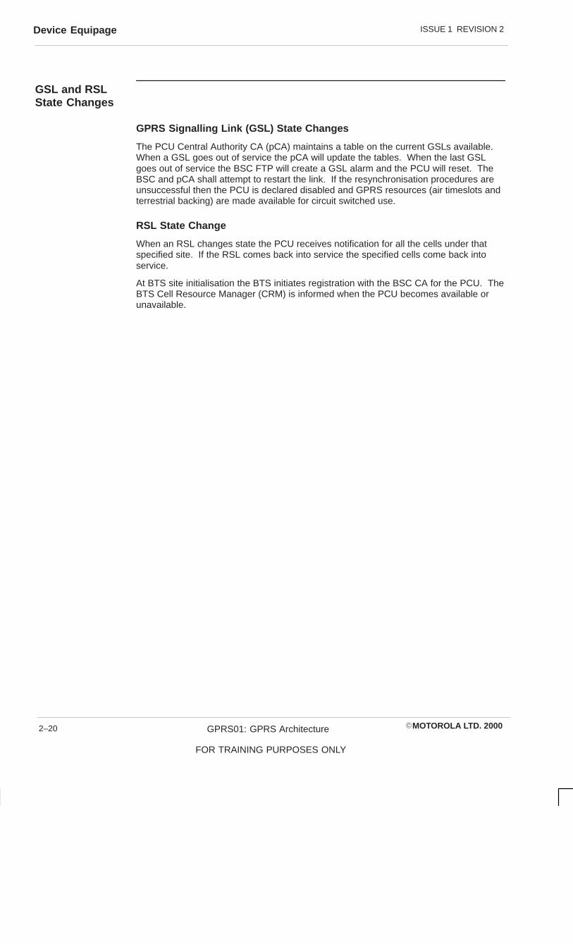
ISSUE 1 REVISION 2Device Equipage
�MOTOROLA LTD. 2000GPRS01: GPRS Architecture
FOR TRAINING PURPOSES ONLY
2–20
GSL and RSLState Changes
GPRS Signalling Link (GSL) State Changes
The PCU Central Authority CA (pCA) maintains a table on the current GSLs available.When a GSL goes out of service the pCA will update the tables. When the last GSLgoes out of service the BSC FTP will create a GSL alarm and the PCU will reset. TheBSC and pCA shall attempt to restart the link. If the resynchronisation procedures areunsuccessful then the PCU is declared disabled and GPRS resources (air timeslots andterrestrial backing) are made available for circuit switched use.
RSL State Change
When an RSL changes state the PCU receives notification for all the cells under thatspecified site. If the RSL comes back into service the specified cells come back intoservice.
At BTS site initialisation the BTS initiates registration with the BSC CA for the PCU. TheBTS Cell Resource Manager (CRM) is informed when the PCU becomes available orunavailable.

ISSUE 1 REVISION 2 Device Equipage
�MOTOROLA LTD. 2000 GPRS01: GPRS Architecture
FOR TRAINING PURPOSES ONLY
2–21
GPRS Signalling Link (GSL) State Changes
Last GSL OOS
– GSL ALARM
– PCU RESET
– GB DISCONNECT
RSL State Changes
– PCU notified of cell state change
– BTS CRM QUERY BSC CA for PCU STATUS

ISSUE 1 REVISION 2Device Equipage
�MOTOROLA LTD. 2000GPRS01: GPRS Architecture
FOR TRAINING PURPOSES ONLY
2–22
Carrier StateChanges
The respective packet scheduler for the cell receives Carrier State Change messagefrom the Cell Resource Manager (CRM) when a GPRS carrier it is responsible for goesout of service. The Packet Scheduler (PS) notifies the SGSN of the cell being out ofservice via the GB manager.
If the carrier out of service is not the BCCH carrier then new system information may besent to indicate GPRS unavailable.

ISSUE 1 REVISION 2 Device Equipage
�MOTOROLA LTD. 2000 GPRS01: GPRS Architecture
FOR TRAINING PURPOSES ONLY
2–23
CRM PS/SYSINFO
GBM SGSN
CARRIER STATECHANGE
CELL OOS
BVC BLOCK
CARRIER STATECHANGE ACK
BVC BLOCK ACK
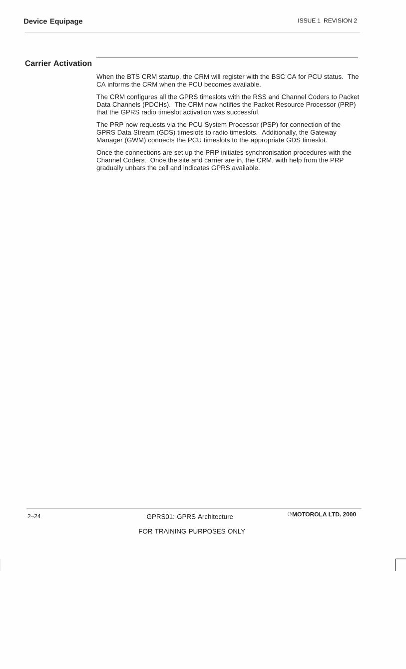
ISSUE 1 REVISION 2Device Equipage
�MOTOROLA LTD. 2000GPRS01: GPRS Architecture
FOR TRAINING PURPOSES ONLY
2–24
Carrier Activation
When the BTS CRM startup, the CRM will register with the BSC CA for PCU status. TheCA informs the CRM when the PCU becomes available.
The CRM configures all the GPRS timeslots with the RSS and Channel Coders to PacketData Channels (PDCHs). The CRM now notifies the Packet Resource Processor (PRP)that the GPRS radio timeslot activation was successful.
The PRP now requests via the PCU System Processor (PSP) for connection of theGPRS Data Stream (GDS) timeslots to radio timeslots. Additionally, the GatewayManager (GWM) connects the PCU timeslots to the appropriate GDS timeslot.
Once the connections are set up the PRP initiates synchronisation procedures with theChannel Coders. Once the site and carrier are in, the CRM, with help from the PRPgradually unbars the cell and indicates GPRS available.

ISSUE 1 REVISION 2 Device Equipage
�MOTOROLA LTD. 2000 GPRS01: GPRS Architecture
FOR TRAINING PURPOSES ONLY
2–25
BSC SM BSC CA BTS PSP PICPPRP (per cell procedures)
GPRS Carrier Status
Note that the BTS shall initiate entitynotification registrationat site init and RSLinservice
BSC CA has beennotified the PCU is in–service
PCU Available
PCU Ins
PCU Connection Requests (radio channel/PCU timeslot)
PCU Connection Requests (radio channel/PCU timeslot)
OK
PCU Connection Assignments
PCU Connection Assignments
Packet SystemInformation
(to bar mobiles)
Initiate synchronizationwith the Channel Coders

ISSUE 1 REVISION 2Device Equipage
�MOTOROLA LTD. 2000GPRS01: GPRS Architecture
FOR TRAINING PURPOSES ONLY
2–26
MobileOriginatedPacket Accessand Transfer
On initiation of uplink packet transfer the BSS shall provide the capability to handle apacket channel request on a Packet Associated Control Channel (PACCH). On receiptof a RACH the RSS forwards the RACH to the Packet Scheduler. The resource isassigned by the Packet Scheduler and the Access Grant functional unit generates theimmediate assignment which is returned to the RSS for transmission on AGCH.
After access and assignment the Uplink functional unit will collect all the radio blocks sentfrom the MS, identified by the Temporary Flow Indentifier (TFI) and reassemble all theradio blocks for each TFI into an Logical Link Control (LLC) frame. The LLC frame isthen sent to the Gb functional unit to be placed in an uplink queue to be serviced byFrame Relay and sent to the SGSN.

ISSUE 1 REVISION 2 Device Equipage
�MOTOROLA LTD. 2000 GPRS01: GPRS Architecture
FOR TRAINING PURPOSES ONLY
2–27
RSS
CHANNEL REQUEST
MS ACCESSGRANT FU
CHANNEL REQUEST (ON THE RACH)
IMMEDIATE ASSIGNMENTIMMEDIATE ASSIGNMENT (ON THE AGCH)
MS UPLINK FU
ASSEMBLE FU
GB FR SGSNACCESS ANDASSIGNMENT
PDTCH
PDTCH
PDTCH
DATA BLOCK
DATA BLOCK
DATA BLOCK
PACCH
PDTCH
PDTCH
PACCH
TEMPORARY PACKET ACK/NACK
DATA BLOCK
DATA BLOCK (LAST)
FINAL PACKETACK/NACK

ISSUE 1 REVISION 2Device Equipage
�MOTOROLA LTD. 2000GPRS01: GPRS Architecture
FOR TRAINING PURPOSES ONLY
2–28
MobileTerminatedPacket Accessand Transfer
On receipt of a Paging message from the SGSN, the pCA will forward a Packet PagingRequest over the PCH. The MS will respond with a Packet Channel Request on thePACH and following an assignment will move to the assigned Packet Data Channels(PDCHs) and send a Packet Paging Response, which has a Temporary Logical LinkIdentity (TLLI) and an Logical Link Control (LLC) frame with a TLLI.
On receipt of the LLC frame from the SGSN, the Frame Relay unit strips out the FrameRelay header and passes the frame onto the Gb functional unit, which strips off theBSSGP header and passes the frame down to the segmentation functional unit, whichsplits the frame into RLC/MAC radio blocks for sending on PDCHs assigned to themobile.

ISSUE 1 REVISION 2 Device Equipage
�MOTOROLA LTD. 2000 GPRS01: GPRS Architecture
FOR TRAINING PURPOSES ONLY
2–29
PACKET CHANNEL REQUEST
MS ACCESSGRANT FU
(ON THE RACH)
PACKET IMMEDIATE ASSIGNMENT(ON THE AGCH)
MS DL FU SEGMENTATI
ON
GB FR SGSNACCESS ANDASSIGNMENT
PDTCH
PDTCH
PDTCH
DATA BLOCK
DATA BLOCK
DATA BLOCK (POLLING)
PACCH
PDTCH
PACCH
PACCH
TEMPORARY PACKET ACK/NACK
DATA BLOCK
DATA BLOCK (LAST POLLING))
FINAL PACKET ACK/NACK
PACKET RESOURCE REQUEST
PACKET RESOURCE ASSIGNMENTOPTIONAL
PACCH
PACCH
PDTCHDATA BLOCK

ISSUE 1 REVISION 2Device Equipage
�MOTOROLA LTD. 2000GPRS01: GPRS Architecture
FOR TRAINING PURPOSES ONLY
2–30
Gb Interface
The interface to the SGSN is a new network interface for the BSS defined by GPRS asthe Gb interface. The Gb interface is a packet interface using Frame Relay PVCs. Twotypes of information flow on the Gb interface, signalling and data. Two protocols workover the Gb interface, these are the Base Station System GPRS Protocol (BSSGP)protocol and the underlying NS (Frame Relay).
Frame Relay includes Network and Link layer functions. It performs data transmission,load sharing and link layer node management.
The BSSGP layer provides Quality of Service (QoS), radio and routing and signalling fornode management between the BSS and the SGSN. The BSS provides downlink flowcontrol between the BSS and the SGSN, it consists of:
� One queue per cell provided in the BSSGP layer
� Flow Control

ISSUE 1 REVISION 2 Device Equipage
�MOTOROLA LTD. 2000 GPRS01: GPRS Architecture
FOR TRAINING PURPOSES ONLY
2–31
PCU SGSN
BSSGP
NS
FR
EI
BSSGP
NS
FR
EI

ISSUE 1 REVISION 2Device Equipage
�MOTOROLA LTD. 2000GPRS01: GPRS Architecture
FOR TRAINING PURPOSES ONLY
2–32
Frame RelayFunctional Unit
At the time of system setup of the Packet Control Unit (PCU), the Frame Relay functionalunit will be initialised. The transmit and receive buffers and the timer resources areinitialised on the Packet Interface Control Processor (PICP) for Layer 2 buffering of uplinkand downlink data on the Gb interface.
The Frame Relay functional unit will hold in Non Volatile memory a mapping of local DLCIand the physical interface (i.e. E1). The SGSN also holds a similar mapping. Each PCUwill only be able to connect to one and only one SGSN.
DLCI 0 is used to send PVC status messages. The maximum number of DLCIs that canbe indicated in the frame size of 1600 octets is 318. This means that 318 DLCIs can beset up per physical bearer. The status messages are used to confirm the end to endavailability of all PVCs on a GBL.

ISSUE 1 REVISION 2 Device Equipage
�MOTOROLA LTD. 2000 GPRS01: GPRS Architecture
FOR TRAINING PURPOSES ONLY
2–33
Frame Relay Functional Unit
– Transmit and Receive Buffers
– NVRAM MAPPING DLCI + GBL
– DLCI O PVC STATUS MESSAGES

ISSUE 1 REVISION 2Device Equipage
�MOTOROLA LTD. 2000GPRS01: GPRS Architecture
FOR TRAINING PURPOSES ONLY
2–34
Gb FunctionalUnit
The Gb functional unit is divided into the following processes:
� Gb Manager (GBM)
� Gb Router (GR)
� Gateway Transmit Manager (GTM)
� Network Service Test (NST)
� Flow Control Buffer Manager (FBM)
GBM
The GB Manager manages BSSGP Virtual Circuit (BVC) (cell) and NS–VC (PVC)management procedures. The Gb Manager (GBM) maintains internal tables monitoringthe state of BVCs and NS–VCs and the mapping between them. The GBM isresponsible for the monitoring of the Gbl link status and generating the appropriatealarms. The GBM will inform the Gateway Manager (GWM) of any change in GBLstatus.
The GBM manages the BVC and NS–VC block, reset and unblock procedures. It shallgenerate the appropriate alarms. The FR functional unit at the Packet Control Unit(PCU) shall detect when the last GBL goes out of service and reports it to the GBM,which in turn reports the event to the pFTP and informs the pFCP to generate an alarm.
The GBM is also responsible for sending Radio Status messages to the SGSN (i.e. BTSnot MS) and the handling of Routing Area (RA) capability procedures.

ISSUE 1 REVISION 2 Device Equipage
�MOTOROLA LTD. 2000 GPRS01: GPRS Architecture
FOR TRAINING PURPOSES ONLY
2–35
Gb Functional Unit
NST
Gb Manager
Flow ControlBuffer Manager
GatewayTransmitManager
Gb Router

ISSUE 1 REVISION 2Device Equipage
�MOTOROLA LTD. 2000GPRS01: GPRS Architecture
FOR TRAINING PURPOSES ONLY
2–36
Gb Router (GR)
The Gb Router (GR) validates and routes downlink PDUs. The GR routes the downlinkPDUs to the appropriate Flow Control Buffer Manager (FBM) which will pass the PDU tothe air functional units for transmission over the air.
The GR is also responsible for the routing of paging messages to the appropriate Pagingfunction on a Packet Resource Processor.
GatewayTransmitManager
The Gateway Transmit Manager (GTM) gathers and transmits uplink PDUs on thecorrect NS–VC. The air functional unit concatenates the uplink Logical Link Control(LLC) frame and the load sharing function chooses the appropriate NS–VC from theNS–VC group serving the BSSGP Virtual Circuit Identifier (BVCI) for transmission by theGbFu to the SGSN. The GTM gathers the PDUs from the various cells and passes themto the FR functional unit for transmission over a given DLCI and Gbl.
Network ServiceTest
The Network Service Test (NST) periodically tests NS–VCs to see if they are alive. TheNST also sends test messages on each alive NS–VC and responds to test messagesfrom the SGSN by sending back an acknowledgement on the same NS–VC.
Flow ControlBuffer Manager(FBM)
The Flow Control Buffer Manager ensures that opened downlink LLC frames aretransmitted over the air within their delay class limitations. The FBM performs flowcontrol using either XON/XOFF or the ‘leaky bucket’ algorithm. When using the ‘leakybucket’ algorithm the configurable parameters of the maximum size of the downlink bufferand maximum data rate the SGSN can transmit data to the mobiles will govern thealgorithm. The FBM will send at a configurable interval flow control messages to theSGDN to govern the downlink data transfer.
The FBM is also responsible for the flushing of a mobile LLC PDUs from a cell queue forthat mobile and informing the packet scheduler to delete the mobiles context for that cell.

ISSUE 1 REVISION 2 Device Equipage
�MOTOROLA LTD. 2000 GPRS01: GPRS Architecture
FOR TRAINING PURPOSES ONLY
2–37
NST
– Periodic testing of NSVCs
– Ensure queued dl LLC frames transmitted within their delay class
– Flushing of LLC frames
FBM

ISSUE 1 REVISION 2Device Equipage
�MOTOROLA LTD. 2000GPRS01: GPRS Architecture
FOR TRAINING PURPOSES ONLY
2–38
FaultManagement
The Fault Management software at the Packet Control Unit (PCU) may be split into twomain areas; the fault detection and handling system and the Central Authority (pCA).The Fault Management software is responsible for the detection of any alarms anddeciding upon any hardware /software reconfiguration in response to these alarms.
The PCU Central Authority, under the direction of the fault handling and detectionsystem, is responsible for carrying out the reconfiguration.

ISSUE 1 REVISION 2 Device Equipage
�MOTOROLA LTD. 2000 GPRS01: GPRS Architecture
FOR TRAINING PURPOSES ONLY
2–39
Fault Management
Fault Detection and Handling
CentralAuthority

ISSUE 1 REVISION 2Device Equipage
�MOTOROLA LTD. 2000GPRS01: GPRS Architecture
FOR TRAINING PURPOSES ONLY
2–40
Fault Detectionand HandlingSystem
This area of Operations and Maintenance is responsible for the detection, collection,reporting and deciding actions to be taken if faults appear in the Packet Control Unit(PCU).
The system is based around three processes:
1. The Fault Collection Process (pFCP)
This process exists at every DPROC at a site. It collects alarm reports from all processesthat exist on its particular DPROC. This process automatically acknowledges receipt ofan alarm and then passes all alarms indications up to the fault translation process.
2. Fault Translation Process (pFTP)
This process exists on the PCU System Processor (PSP) as part of the GWM functionalunit, and works with various processes to keep the integrity of the site. All alarms at thePCU are reported to the pFTP. The pFTP forwards alarms to the Agent at the BSC andgenerates messages to the pCA for device transitions, as needed, based on faultsreported.
3. System Audit Process (pSAP)
The System Audit Process exists on every DPROC at a site. This process periodicallyaudits the PCU software and any faults found are forwarded to the Fault TranslationProcess via the Fault Collection Process.

ISSUE 1 REVISION 2 Device Equipage
�MOTOROLA LTD. 2000 GPRS01: GPRS Architecture
FOR TRAINING PURPOSES ONLY
2–41
Fault Translation Process
OMC-R
AGENT
pCA
pFTP
pFCP
PCU DEVICES

ISSUE 1 REVISION 2Device Equipage
�MOTOROLA LTD. 2000GPRS01: GPRS Architecture
FOR TRAINING PURPOSES ONLY
2–42
System AuditProcess
The Packet Control Unit (PCU) System Audit Process follows much the samearchitecture as the BSS. A Site System Audit Process (pSSAP) resides on the PCUSystem Processor (PSP) as part of the Gateway Manager (GWM) functional unit. ThePSP performs the audits of the PCU and communicates directly with the BSC MMI andSAP.
The DPROCs contain a local process responsible for auditing the DPROC upon which itresides.
The SAP will detect faulty/degrading hardware and software through the use of audittests and if a failure is detected it is reported to the pfTP.
There are three types of System Audit Process:
� Site System Audit Process – one per site and will result in an audit of all availablehardware in the PCU.
� Cage System Audit Process – has the same functionality as the Site System AuditProcess. This has been provided for future multi cage PCUs.
� Device System Audit Process – responsible for auditing the device on which itresides.
The System Operator can turn the audit functionality ON/OFF on a device, cage or persite basis. The System Operator can modify the audit schedules for a specific device orcage, e.g. device audit.

ISSUE 1 REVISION 2 Device Equipage
�MOTOROLA LTD. 2000 GPRS01: GPRS Architecture
FOR TRAINING PURPOSES ONLY
2–43
System Audit Process
� Monitor the status of the PCU
� Three types of Audit process
– Site System Audit Process (pSSAP)
– Cage System Audit Process (pCSAP)
– Device Audit Process
� MMI Control (OMC, TTY)

ISSUE 1 REVISION 2Device Equipage
�MOTOROLA LTD. 2000GPRS01: GPRS Architecture
FOR TRAINING PURPOSES ONLY
2–44
ConfigurationManagement
The Configuration Management (CM) Software is responsible for managing and updatingthe main configuration database at either a BSC, BTS or PCU. This database isdownloaded as an object file and contains all the site parameters such as siteconfiguration and device functionality distribution.
The CM process at the BSC communicates with the pCM process in the same manneras a remote BTS. If database changes are listed as at the PCU then the BSC CM willforward the changes to the PCU Configuration Management (pCM). There is no MMIfunctionality at the PCU so the pCM has reduced functionality compared to the CM at theBSC.
The pCM process resides on the PCU System Processor (PSP) as part of the GatewayManager functional unit. The pCM receives the CM database object from the BSC. Aftertranslation the database object is stored on compact flash on the PSP. The translatedobject is cross–loaded to the DPROC boards equipped in the database with code objectsat initialisation.

ISSUE 1 REVISION 2 Device Equipage
�MOTOROLA LTD. 2000 GPRS01: GPRS Architecture
FOR TRAINING PURPOSES ONLY
2–45
Configuration Management
BSC CM BSC CA
PSP pCM
Compact Flash Memory
MASTERDATABASE
Slave pCM Slave pCM
Database Copy
Database Copy
DPROC DPROC

ISSUE 1 REVISION 2Device Equipage
�MOTOROLA LTD. 2000GPRS01: GPRS Architecture
FOR TRAINING PURPOSES ONLY
2–46
PCU CentralAuthority (pCA)
On site initialisation, the central authority (pCA) process is created and queries thedatabase to obtain site configuration and device equipage data. The central authority isthen responsible for creating all the necessary software processes on the DPROCS, aswell as downloading and ”bringing into service” all peripheral boards and devices. Oncompletion of site initialisation, the pCA then works as an independent process with adynamic database keeping track of the state of all devices and software functions on itssite.
If a fault indication occurs at the site and the fault detection and handling system decidesthat a device or software identity must be taken out of service, then it is the pCA that willperform this task. If the fault detection and handling system decides to bring anotherdevice or software entity into service, in response to that alarm indication then it is thepCA that will supervise the downloading/initialisation of the device or software entity. Itmay be the case that the system operator wishes to remove or insert a device fromservice with a MMI command, it is the pCA that carries out the action.
In both of the above cases, once the reconfiguration has occurred, the pCA will updatethe device state of each entity in its dynamic database.
However, if the site is re–initialised the pCA process is lost and the device states areerased. The pCA is then created by the initialisation process, the pCA reads thedatabase and the initialisation procedure starts again.
The pCA is responsible for informing the router process when software processes arecreated, destroyed or moved. This allows the router process to modify the router tableswhich are used by the executive to support the ”flexible interprocess communications”feature.

ISSUE 1 REVISION 2 Device Equipage
�MOTOROLA LTD. 2000 GPRS01: GPRS Architecture
FOR TRAINING PURPOSES ONLY
2–47
PCU Central Authority Functions
A. Site Initialisation
1. Queries for database for site configuration and equipage.
2. Downloading software to the hardware
3. Create Software on DPROCS
4. Creating routing tables
5. Creating state tables
B. Initiate and Direct Configuration Changes
1. Hardware
2. Software
3. Updating Router
4. Updating state tables

ISSUE 1 REVISION 2Device Equipage
�MOTOROLA LTD. 2000GPRS01: GPRS Architecture
FOR TRAINING PURPOSES ONLY
2–48

�MOTOROLA LTD. 2000 GPRS01: GPRS Architecture
FOR TRAINING PURPOSES ONLY
i
Chapter 3
BSS/PCU Commands

ISSUE 1 REVISION 2
�MOTOROLA LTD. 2000GPRS01: GPRS Architecture
FOR TRAINING PURPOSES ONLY
ii

ISSUE 1 REVISION 2
�MOTOROLA LTD. 2000 GPRS01: GPRS Architecture
FOR TRAINING PURPOSES ONLY
iii
Chapter 3BSS/PCU Commands i. . . . . . . . . . . . . . . . . . . . . . . . . . . . . . . . . . . . . . . . . . . . . . .
Objectives 3–1. . . . . . . . . . . . . . . . . . . . . . . . . . . . . . . . . . . . . . . . . . . . . . . . . . . . . . . . . . . . . . . . .
PCU 3–2. . . . . . . . . . . . . . . . . . . . . . . . . . . . . . . . . . . . . . . . . . . . . . . . . . . . . . . . . . . . . . . . . . . . . . PSP 3–2. . . . . . . . . . . . . . . . . . . . . . . . . . . . . . . . . . . . . . . . . . . . . . . . . . . . . . . . . . . . . . . . . Dependencies 3–2. . . . . . . . . . . . . . . . . . . . . . . . . . . . . . . . . . . . . . . . . . . . . . . . . . . . . . . .
DPROC 3–4. . . . . . . . . . . . . . . . . . . . . . . . . . . . . . . . . . . . . . . . . . . . . . . . . . . . . . . . . . . . . . . . . . .
MSI 3–6. . . . . . . . . . . . . . . . . . . . . . . . . . . . . . . . . . . . . . . . . . . . . . . . . . . . . . . . . . . . . . . . . . . . . . .
MMS Device 3–8. . . . . . . . . . . . . . . . . . . . . . . . . . . . . . . . . . . . . . . . . . . . . . . . . . . . . . . . . . . . . . . MMS Priority 3–8. . . . . . . . . . . . . . . . . . . . . . . . . . . . . . . . . . . . . . . . . . . . . . . . . . . . . . . . . GDS or GBL 3–8. . . . . . . . . . . . . . . . . . . . . . . . . . . . . . . . . . . . . . . . . . . . . . . . . . . . . . . . . .
GPRS Data Stream (GDS) 3–10. . . . . . . . . . . . . . . . . . . . . . . . . . . . . . . . . . . . . . . . . . . . . . . . . . .
GPRS Signalling Link (GSL) 3–12. . . . . . . . . . . . . . . . . . . . . . . . . . . . . . . . . . . . . . . . . . . . . . . . . .
GBL Device 3–14. . . . . . . . . . . . . . . . . . . . . . . . . . . . . . . . . . . . . . . . . . . . . . . . . . . . . . . . . . . . . . . .
LCF 3–16. . . . . . . . . . . . . . . . . . . . . . . . . . . . . . . . . . . . . . . . . . . . . . . . . . . . . . . . . . . . . . . . . . . . . . .
GPRS Carrier 3–18. . . . . . . . . . . . . . . . . . . . . . . . . . . . . . . . . . . . . . . . . . . . . . . . . . . . . . . . . . . . . .
Reconfiguration of suitable GPRS PDCHs 3–20. . . . . . . . . . . . . . . . . . . . . . . . . . . . . . . . . . . . .
BSSGP Virtual Circuit (BVC) Blocking and Unblocking 3–22. . . . . . . . . . . . . . . . . . . . . . . . . . .
BVC Reset 3–24. . . . . . . . . . . . . . . . . . . . . . . . . . . . . . . . . . . . . . . . . . . . . . . . . . . . . . . . . . . . . . . . .
Flow Control 3–26. . . . . . . . . . . . . . . . . . . . . . . . . . . . . . . . . . . . . . . . . . . . . . . . . . . . . . . . . . . . . . .
Network Service Block, Reset, Unblock, Test 3–28. . . . . . . . . . . . . . . . . . . . . . . . . . . . . . . . . . .
Network Service Test 3–30. . . . . . . . . . . . . . . . . . . . . . . . . . . . . . . . . . . . . . . . . . . . . . . . . . . . . . . .
Network Service 3–32. . . . . . . . . . . . . . . . . . . . . . . . . . . . . . . . . . . . . . . . . . . . . . . . . . . . . . . . . . . .
Network Service Virtual Connection Group 3–34. . . . . . . . . . . . . . . . . . . . . . . . . . . . . . . . . . . . .
Gb Addressing 3–36. . . . . . . . . . . . . . . . . . . . . . . . . . . . . . . . . . . . . . . . . . . . . . . . . . . . . . . . . . . . .
Network Service Virtual Connection 3–38. . . . . . . . . . . . . . . . . . . . . . . . . . . . . . . . . . . . . . . . . . .
BSSGP Virtual Circuit Identifier (BVCI) 3–40. . . . . . . . . . . . . . . . . . . . . . . . . . . . . . . . . . . . . . . .
GPRS Signalling BVCI 3–42. . . . . . . . . . . . . . . . . . . . . . . . . . . . . . . . . . . . . . . . . . . . . . . . . . . . . .
Routing Area 3–44. . . . . . . . . . . . . . . . . . . . . . . . . . . . . . . . . . . . . . . . . . . . . . . . . . . . . . . . . . . . . . .
N3102 3–46. . . . . . . . . . . . . . . . . . . . . . . . . . . . . . . . . . . . . . . . . . . . . . . . . . . . . . . . . . . . . . . . . . . . .

ISSUE 1 REVISION 2
�MOTOROLA LTD. 2000GPRS01: GPRS Architecture
FOR TRAINING PURPOSES ONLY
iv
ISSUE 1 REVISION 2 Objectives
�MOTOROLA LTD. 2000 GPRS01: GPRS Architecture
FOR TRAINING PURPOSES ONLY
3–1
ObjectivesOn completion of this chapter the student will be able to:
� Describe the device/function dependancy within the database structure
� Equip and understand the database fields associated with equipping a PCU

ISSUE 1 REVISION 2PCU
�MOTOROLA LTD. 2000GPRS01: GPRS Architecture
FOR TRAINING PURPOSES ONLY
3–2
PCUEquipping a PCU at a BSS is done using the equip 0 pcu command. Equipping the PCUautomatically equips the cab and cage. Only one CAB and one cage can be equippedwith a PCU.
Restrictions to the PCU equipage are:
� PCU cannot be equipped when the GPRS feature is restricted.
� One PCU only per BSS
� PCU can only be equipped if land_layer_l_mode is set to E1
PSP
The PCU System Processor (PSP) is equipped on the MPROC at the PCU. Is thedevice that describes an MPROC board which is the master processor in the PCU.
Dependencies
� GPRS feature must be unrestricted
� PSP may only be equipped at a PCU
� Sysgen mode cannot be left if a PCU is equipped and no PSP is equipped

ISSUE 1 REVISION 2 PCU
�MOTOROLA LTD. 2000 GPRS01: GPRS Architecture
FOR TRAINING PURPOSES ONLY
3–3
equip 0 pcu
��������������� �
�������
����
equip PCU PSP
Enter the PSP identifier: 0

ISSUE 1 REVISION 2DPROC
�MOTOROLA LTD. 2000GPRS01: GPRS Architecture
FOR TRAINING PURPOSES ONLY
3–4
DPROCThe Data Processor Board is the non–system processor board at the PCU. Theseboards may have up to two PMC modules fitted dependent on the required function.
DPROCs may only be fitted and equipped in slots 1 – 6 and slots 11 – 16, the remainingslots being taken by the MPROC and the PCI to PCI Bridge (PPB).
There are two types of DPROC, Packet Interface Control Processor (PICP) and PacketResource Processor. A maximum of 6 PICPs may be equipped at the PCU and amaximum of 10 PRPs may be equipped at the PCU.
PRPs should not be equipped in slots 1 and 2 of the PCU cage as the default slot oninitialisation to bring up the GPRS Signalling Link (GSL) to gain code download is via slot1 or 2 through a PICP.

ISSUE 1 REVISION 2 DPROC
�MOTOROLA LTD. 2000 GPRS01: GPRS Architecture
FOR TRAINING PURPOSES ONLY
3–5
equip PCU DPROC
Enter the DPROC ID: <*>
* 1–6, 11–16
Enter the DPROC type: <*>
* PRP or PICP

ISSUE 1 REVISION 2MSI
�MOTOROLA LTD. 2000GPRS01: GPRS Architecture
FOR TRAINING PURPOSES ONLY
3–6
MSITo equip the PMC module the MSI device has been modified. The PMC module is usedto support the connection of the GBL to the PCU or the GPRS Data Stream (GDS) andGPRS Signalling Link (GSL) to the PCU.
These is a new MSI type called the E1–PMC to add this interface card to the MSI device.
To equip the E1–PMC MSI can only be carried out at a PCU. A maximum of 12 DPROCPICP MSIs can be equipped with a maximum of two E1–PMCs to any PICP. Each PRPmay be equiped with up to 2 MSI.
The first identifier of the E1–PMC must be unique, the second refers to the DPROC thatthe E1–PMC is mounted on.
The final prompt for the DPROC socket refers to the module identifier for the DPROCboard that the E1–PMC is being equipped. Each DPROC is capable of holding twoE1–PMCs.

ISSUE 1 REVISION 2 MSI
�MOTOROLA LTD. 2000 GPRS01: GPRS Architecture
FOR TRAINING PURPOSES ONLY
3–7
equip PCU MSI
Enter the MSI identifier: <*>* 0–23
Enter the DPROC id: <*>* 1–6, 11–16
Enter the DPROC Socket: <*>* 1,2

ISSUE 1 REVISION 2MMS Device
�MOTOROLA LTD. 2000GPRS01: GPRS Architecture
FOR TRAINING PURPOSES ONLY
3–8
MMS DeviceTo equip the two ports on the PMC module the MMS command has been extended. TheMMSs for a PMC are automatically equipped when a MSI is equipped.
MMS Priority
The MMS priority for a PICP MMS may not be set to a non–zero value, nor can the MMSat the BSC that is part of a GPRS Data Stream (GDS).
GDS or GBL
All MMSs on the same MSI must be configured for the same destination.

ISSUE 1 REVISION 2 MMS Device
�MOTOROLA LTD. 2000 GPRS01: GPRS Architecture
FOR TRAINING PURPOSES ONLY
3–9
MMS Device
PICP
PMC 860E1
PMC 860E1
E1
E1
E1
E1GBL
GDS

ISSUE 1 REVISION 2GPRS Data Stream (GDS)
�MOTOROLA LTD. 2000GPRS01: GPRS Architecture
FOR TRAINING PURPOSES ONLY
3–10
GPRS Data Stream (GDS)The GPRS Data Stream device refers to the traffic route between the PCU and the BSC.This is a E1 connection between a BSC MMS and a PCU MMS. The GPRS DataStream (GDS) may or may not have an associated GPRS Signalling Link (GSL). If theGDS carries a GSL then one timeslot is required for GSL LAPD signalling, the rest forGPRS traffic.
A maximum of 12 GDSs may be equipped and to allow default connectivity for codedownload for the PCU a GDS must be equipped and GSL equipped to the GDS (LAPD)of either:
� Timeslot 1 of span 0 of an E1–PMC Module in PMC Socket 1 of a PICP in Slot 1
� Timeslot 1 of span 0 of an E1–PMC module in PMC Socket 1 of a PICP in Slot 2

ISSUE 1 REVISION 2 GPRS Data Stream (GDS)
�MOTOROLA LTD. 2000 GPRS01: GPRS Architecture
FOR TRAINING PURPOSES ONLY
3–11
equip PCU GDS
Enter the GDS Identifier: <*>* 0–11
Enter the BSC MMS Identifier: <*> <*>
Enter the PCU MMS Identifier: <*> <*>
Enter the GDS type: <*>0 – TRAU GDS1 – LAPD GDS

ISSUE 1 REVISION 2GPRS Signalling Link (GSL)
�MOTOROLA LTD. 2000GPRS01: GPRS Architecture
FOR TRAINING PURPOSES ONLY
3–12
GPRS Signalling Link (GSL)The GPRS Signalling LInk (GSL) is a 64Kbps LAPD signalling link on a timeslot on aGPRS Data Stream (GDS). The GSL is used for signalling and code download forcommunication between the PCU and the GSL.
The maximum GSLs that may be equipped to a PCU are 6, with a maximum of twoGSLs to any GDS. The first GSL equipped to a GDS will use timeslot 1 of the GDS andthe second GSL equipped to the same GDS will use timeslot 2.
A GSL must be equipped to the default location to allow code download. The maximumnumber of GSLs equipped must not exceed the maximum number of GSLs that the LCFscan manage.

ISSUE 1 REVISION 2 GPRS Signalling Link (GSL)
�MOTOROLA LTD. 2000 GPRS01: GPRS Architecture
FOR TRAINING PURPOSES ONLY
3–13
equip PCU GSL
Enter the GSL identifier: <*>* 0–5
Enter the Unique GDS identifier: <*>* 0–11

ISSUE 1 REVISION 2GBL Device
�MOTOROLA LTD. 2000GPRS01: GPRS Architecture
FOR TRAINING PURPOSES ONLY
3–14
GBL DeviceThe GBL device refers to the configured number of timeslots on a E1 span between thePCU and the SGSN. This is the physical interface for the Frame Relay network service.One GBL is allowed per E1 span, the number of timeslots is a configurable parameter.
To maintain the Frame Relay link, unidirectional signalling incorporates periodic pollingbetween the PCU and the network. The PCU sends a STATUS ENQUIRY messageevery polling cycle (governed by T391) the network responds with a STATUS message.A count of the polling cycles is kept by the counter N391 at a set number of polling cyclescalled a FULL STATED ENQUIRY message is sent.
The network may also POLL the PCU set by a Polling Verification timer T392. The ErrorThreshold counter (N392) and the Monitored Events counter (N393) keep track of eventsand errors on the link.

ISSUE 1 REVISION 2 GBL Device
�MOTOROLA LTD. 2000 GPRS01: GPRS Architecture
FOR TRAINING PURPOSES ONLY
3–15
equip PCU GBL
Enter the GBL identifier: <*>* 0–3
Enter the 1st and 2nd MMS identifier:<*> <*>* MSI id 0–11* MMS id 0 or 1
Enter starting timeslot: <*>* 1–31
Enter the ending timeslot: <*>* 1–31
Enter the T391 timer: <*>* 5–29 seconds
Enter the T392 timer: <*>* 6–30 seconds
Enter the N391 counter: <*>* 1–255 polling cycles
Enter the N392 counter: <*>* 1–10 number of errors
Enter the N393 counter: <*>* 1–10 number of events

ISSUE 1 REVISION 2LCF
�MOTOROLA LTD. 2000GPRS01: GPRS Architecture
FOR TRAINING PURPOSES ONLY
3–16
LCFGPRS Signalling Link (GSL) Links are managed at the BSC by LCFs. To manage thisthe LCF device has been modified. The number of GSLs that an LCF can manage isreferred to by max_gsls. This maximum may not exceed 6. The LCF can manage GSLsalong with any combination of other link devices, for example RSLs, CBLs, GSLs, MTLs.
The number of GSLs supported by the LCF must not exceed the maximum number it cansupport.
The maximum number of GSLs per LCF are defined by the number of available GPROCslots and is limited to six. During LCF equipage the maximum number of MTLs , MBLsand GSLs are specified. The total number of these combined must be less than
gproc_slots – Reserved HDLC Channels

ISSUE 1 REVISION 2 LCF
�MOTOROLA LTD. 2000 GPRS01: GPRS Architecture
FOR TRAINING PURPOSES ONLY
3–17
equip bsc LCF
Enter the function ID for the LCF:
Enter the number of MTLS the LCF can manage:
Enter the number of CBLs the LCF can manage:
Enter the number of GSLs the LCF can manage:<*>* 0–6

ISSUE 1 REVISION 2GPRS Carrier
�MOTOROLA LTD. 2000GPRS01: GPRS Architecture
FOR TRAINING PURPOSES ONLY
3–18
GPRS CarrierThe BSS shall support Reserved and Switchable GPRS timeslots. A reserved GPRSTimeslot is a timeslot used for GPRS use only. A Switchable GPRS Timeslot is atimeslot that can be switched from GPRS usage to circuit switched and vice versa.
The BSS supports one GPRS carrier per cell and this carrier may be the BCCH or thenon–BCCH. The maximum number of GPRS timeslots configured depends on whether aseparate GPRS carrier is provided. If a non–BCCH carrier is chosen then up to 8timeslots may be configured for GPRS.
To support this new RTF, parameters have been added:
� max_gprs_pdch
� res_gprs_pdch
The parameter max_gprs_pdch specifies the maximum number of Packet Data Channels(PDCHs)s which will be configured on the carrier starting from the highest order timeslot.The parameter res_gprs_pdch specifies the number of PDCHs configured on the carrierthat will be reserved for GPRS use only. The number of Reserved GPRS timeslots mustnot exceed the maximum GPRS PDCH. All GPRS timeslots must have the same FHIand the same Training Sequence Code.

ISSUE 1 REVISION 2 GPRS Carrier
�MOTOROLA LTD. 2000 GPRS01: GPRS Architecture
FOR TRAINING PURPOSES ONLY
3–19
Timeslot Configuration Examples
BCCHBCCHBCCHBCCH
TCH
BCCHBCCHBCCHBCCH
TCH
SW
SW
RES
RES
RES
TCH
TCH
TCH
TCH
TCH
TCH
TCH
TCH
BCCH
TCH
TCH
TCH
TCH
TCH
TCH
TCH
SW
SW
SW
RES
RES
RES
RES
RES
TCH
TCH
TCH
TCH
TCH
TCH
TCH
SW
SW
SW
SW
SW
SW
SW
SW
0
1
2
3
4
5
6
7
Example A Example B Example C
BCCHCARRIER
CARRIER2
BCCHCARRIER
CARRIER2
BCCHCARRIER
CARRIER2
max_gprs_pdch <*> * 0 – 8res_gprs_pdch <*> * 0 – 8

ISSUE 1 REVISION 2Reconfiguration of suitable GPRS PDCHs
�MOTOROLA LTD. 2000GPRS01: GPRS Architecture
FOR TRAINING PURPOSES ONLY
3–20
Reconfiguration of suitable GPRS PDCHsThe order of priority within a cell is circuit switched calls followed by packet data calls.The BSS supports dynamic switching between Packet Data Traffic Channels (PDTCH)sand TCHs and vice versa. If it is necessary for the BSS to use any switched timeslotsthe BSS shall use them by triggering a reconfiguration frame PDTCH to TCH.
If the timeslot was in use by any GPRS mobiles, the PCU will broadcast the releasenotification on the Packet Associated Control Channels (PACCHs). If there is additionaldownlink data to send the BSS will reassign a channel using the AGCH. If the MS hasmore data to send the PCU will rely on the MS to Re RACH.
When a circuit switched call is greater than gprs_reconfig_thresh_idle_tch then the BSSwill reconfigure the channel back to a PDTCH. If the threshold of idle TCHs has beenexceeded and the cell has gprs_intraho_allwd set then the BSS will perform an intracellhandover of the mobile to an idle TCH and reconfigure the channel to a PDTCH.

ISSUE 1 REVISION 2 Reconfiguration of suitable GPRS PDCHs
�MOTOROLA LTD. 2000 GPRS01: GPRS Architecture
FOR TRAINING PURPOSES ONLY
3–21
Reconfiguration
gprs_intraho_allwd <*>
* 0 = NO INTRACELL HANDOVERS ALLOWED
1 = INTRACELL HANDOVERS ALLOWED
gprs_reconfig_thresh_idle_tch <*>
* 1–5 IDLE RESOURCES

ISSUE 1 REVISION 2BSSGP Virtual Circuit (BVC) Blocking and Unblocking
�MOTOROLA LTD. 2000GPRS01: GPRS Architecture
FOR TRAINING PURPOSES ONLY
3–22
BSSGP Virtual Circuit (BVC) Blocking and UnblockingA BSS may block a BVC because of:
� Operation and maintenance of a cell
� Equipment failure at the BSS
� Cell equipment failure at the BSS
� Cell traffic congestion
The BSS when blocking a BSSGP Virtual Circuit (BVC) will mark the BVC as blocked,discarding any traffic sent to the BVC in the uplink direction. The cell associated with theBVC will not accept any data in the downlink. The BSS sends a BVC_BLOCK PDU tothe SGSN (containing the BSSGP Virtual Circuit Identifier (BVCI) of the BVC to beblocked and a cause element) and starts the timer T1. The SGSN on receipt of theBVC_BLOCK PDU will mark the BVC as blocked and stop transmitting traffic on thatBVC. The SGSN then acknowledges the blocking of the BVC with a BVC_BLOCK_ACKPDU to the BSS. Receipt of the BVC_BLOCK_ACK PDU will stop T1.
If the BVC_BLOCK_ACK PDU is not received before expiry of T1 then the BSS shallrepeat sending the BVC_BLOCK PDU for a maximum of BVC_BLOCK RETRIED.
Unblocking operates in the same method using a BVC_UNBLOCK PDU sent to theSGSN and starting T1, the BSS will re–send the BVC_UNBLOCK PDU forBVC_UNBLOCK RETRIED. On receipt of a BVC_UNBLOCK ACK from a SGSN theBVC is marked as unblocked.

ISSUE 1 REVISION 2 BSSGP Virtual Circuit (BVC) Blocking and Unblocking
�MOTOROLA LTD. 2000 GPRS01: GPRS Architecture
FOR TRAINING PURPOSES ONLY
3–23
BVC Block/Unblock
PCU SGSN
BVC – BLOCK PDU
��
BVC – BLOCK PDU
BVC – BLOCK ACK PDU
BVC – UNBLOCK PDU
BVC – UNBLOCK ACK PDU
��
��
�� ������� � �
� � �����������������
��������� ������
� � ��� ������������ ������
��������� �������������
� � ����� ������������ ������
��������� �������������
��������
�������

ISSUE 1 REVISION 2BVC Reset
�MOTOROLA LTD. 2000GPRS01: GPRS Architecture
FOR TRAINING PURPOSES ONLY
3–24
BVC ResetThe purpose of the BVC_Reset procedure is to resynchronise the GPRS BSSGP VirtualCircuit (BVC) contexts at a BSS and SGSN. This ensures communication in a knownstate. A BVC_Reset procedure could be initiated due to a system failure, an underlyingnetwork service failure or a change in the transmission capability of the underlyingnetwork service.
The sequence is similar to the BVC block/unblock procedure. The BSS or SGSN sendsa BVC_RESET PDU to its Peer and starts the guard timer. bssgp_t2_timer if the entitydoes not receive a BVC_RESET_ACK before expiry of T2 then the entity will re–send theBVC_RESET PDU for BVC_RESET_RETRIES before stopping the procedure andinforming the O&M system. On receipt of a BVC_RESET_ACK the T2 timer is stopped.

ISSUE 1 REVISION 2 BVC Reset
�MOTOROLA LTD. 2000 GPRS01: GPRS Architecture
FOR TRAINING PURPOSES ONLY
3–25
BVC Reset
PCU SGSN
BVC – RESET PDU
�
BVC – RESET PDU
BVC – RESET PDU
�
�
�� ����������� �
� � �����������������
��������� ������
� � ������ ���������� ������
��������� �������������
������
��������
BSSGP_RESET
RETRIES
������
BVC – RESET ACK PDU

ISSUE 1 REVISION 2Flow Control
�MOTOROLA LTD. 2000GPRS01: GPRS Architecture
FOR TRAINING PURPOSES ONLY
3–26
Flow ControlThe principle of flow control is the BSS sends to the SGSN flow control parameters. TheSGSN performs flow control on each MS and BSSGP Virtual Circuit (BVC). The flowcontrol is performed first on each LLC_SDU, first by MS flow control mechanism, andthen by the BVC flow control mechanism.
The convention is that the SGSN should not transmit more data than can be contained inthe BSS buffer for a BVC or individual MS.
The variables sent are a Bucket size for each cell and MS the Bmax should be largeenough to accommodate at least one LLC–SDU. Also sent is the leak rate (R) to beapplied to the bucket. The frequency of flow control information is governed by a setableparameter C.
The formula B* = B + L(p) – (Tc – Tp) x R
Where:
B = Bucket Counter – size of last LLC SDU sent to PCU from the SGSN
B* = Predicted Value of Bucket Counter, which includes the size of the LLC PDUawaiting transmission to the PCU
L(p) = Length of LLC – SDU waiting to be transmitted from the SGSN
Tp = Time the last LLC– SDU was transferred to the PCU
Tc = Arrival time of LLC–SDU at the SGSN from the GGSN
R = Leak rate of the bucket at the PCU
When an LLC–SDU packet arrives at current time Tc, the variable B* is set to thepredicted bucket size as if the LLC–SDU was sent to the BSS. This is given by theprevious bucket size plus the new LLC–SDU size B* = B + L(p). To take account of theleakage since the last compliant LLC–SDU packet the calculation R* (Tc–Tp) is used.
If B* is less than zero then the Bucket Counter is set to the L(p) of the LLC–SDU as is Tpset to Tc and the LLC–SDU is passed as the BSS is ready to receive another LLCpacket.
If B* is not equal to zero but is less than Bmax, in other words would not exceed thebuffer, the LLC packet is passed to the BSS and B is set to B* and Tp to Tc.

ISSUE 1 REVISION 2 Flow Control
�MOTOROLA LTD. 2000 GPRS01: GPRS Architecture
FOR TRAINING PURPOSES ONLY
3–27
Flow Control
Arrival of LLC PDU pwith length L(p) at time Tc
B*= B + L(p) – (Tc – Tp) x R B* < 0?
B= L(p)
Tp= TcB* >Bmax?
B= B*
yes
no
no
Delay LLC PDU Pass LLC PDU�������� ��� �
�� � ��������������������
���������!�� � ��� �� ������� �����
��"��� �����!���������������������
�������������� � � �
��� ����������������������������
����������� ����������������������������������������������
����������������������������������������������

ISSUE 1 REVISION 2Network Service Block, Reset, Unblock, Test
�MOTOROLA LTD. 2000GPRS01: GPRS Architecture
FOR TRAINING PURPOSES ONLY
3–28
Network Service Block, Reset, Unblock, TestThe Gb Manager (GBM) manages the NS–VC block, reset and unblock procedures. AnyNS–VC failure reported by the FR functional unit will result in an NS–VC block being sentto the SGSN by the GBM and informing other PCU processes of the change in NS–VCstatus.
The NS–VC Block PDU will be sent at the expiry of ns_block_timer and forns_block_retries until receipt of NS_BLOCK–ACK PDU.
When an NS_VC comes into service, the GBM first starts a reset procedure to ensurethat both ends are at the same state. The peer entity sends an NS_RESET PDU to itspeer and starts ns_reset timer. At the expiry of the timer the peer re–sends theNS_RESET PDU for a period of time governed by ns_reset_period. Once anNS_RESET ACK has been received the ns_reset_timer is stopped and the NS_VC ismarked as blocked.
The GBM then initiates the Test Procedure on the NS_VC. After initiation of the testprocedure the GBM then unblocks the NS_VC. The peer entity sends an NS_UNBLOCKPDU and starts ns_block_timer. On expiry of the timer the peer entity sends another NSUNBLOCK PDU for NS_UNBLOCK_RETRIES. On receipt of an NS_UNBLOCK_ACKPDU the timer is stopped.

ISSUE 1 REVISION 2 Network Service Block, Reset, Unblock, Test
�MOTOROLA LTD. 2000 GPRS01: GPRS Architecture
FOR TRAINING PURPOSES ONLY
3–29
Network Service
PCU SGSN
NS_UNBLOCK PDU
NS_BLOCKACK PDU
NS_BLOCK PDU
������������� �
�� ����� �����������
���������� ������
�� ������ ������� ������
�� ������� ������� ������
�������������
�� ��� �� �����������
����������� ������
�� ��� �� ������������
��������� ������
NS_BLOCKTIMER
NS_BLOCK PDU
NS_RESET BLOCK PDU
NS_RESET ACK PDU
NS_UNBLOCK ACK PDU
NS_BLOCKTIMER
NS_RESETTIMER
NS_BLOCKTIMER
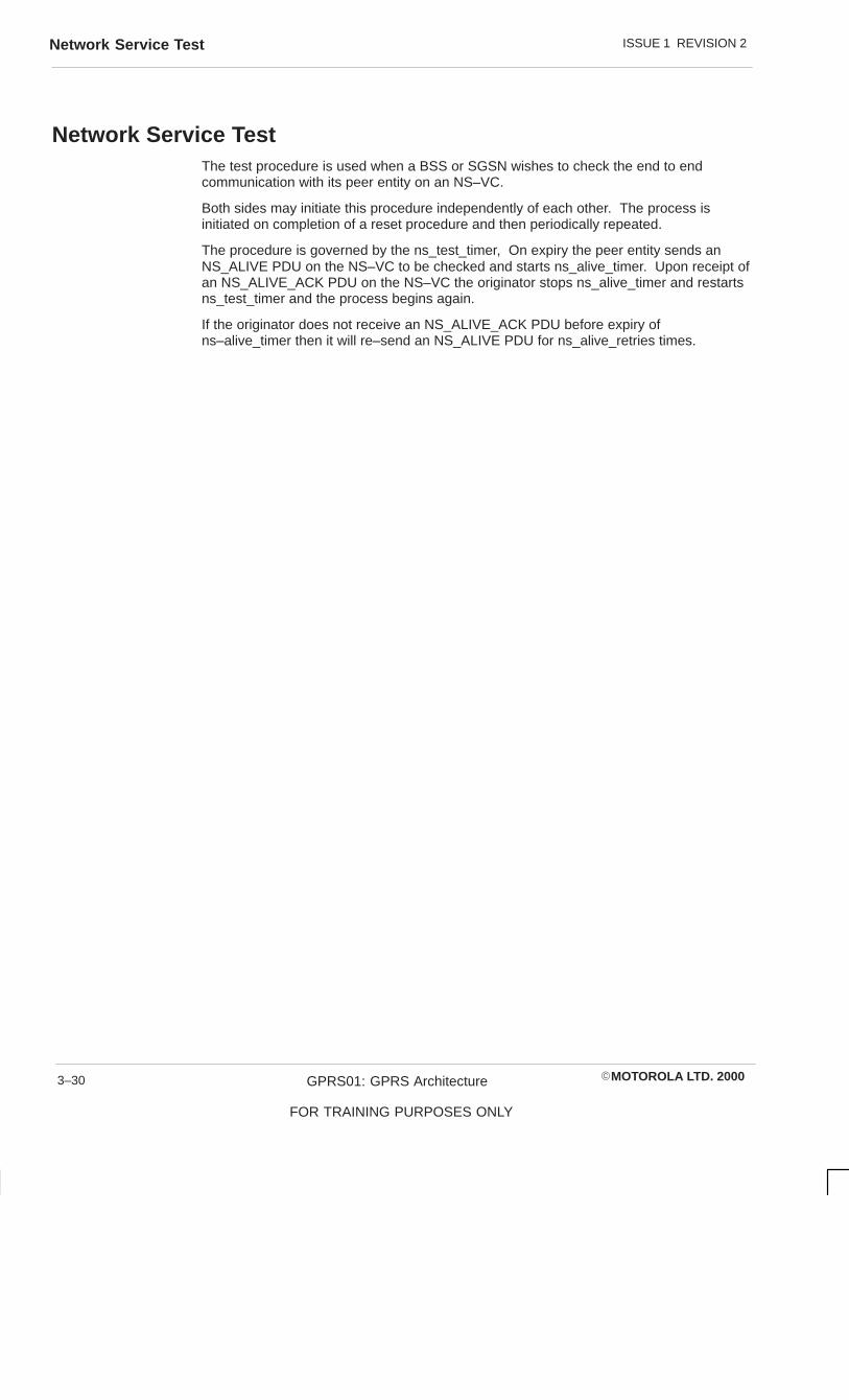
ISSUE 1 REVISION 2Network Service Test
�MOTOROLA LTD. 2000GPRS01: GPRS Architecture
FOR TRAINING PURPOSES ONLY
3–30
Network Service TestThe test procedure is used when a BSS or SGSN wishes to check the end to endcommunication with its peer entity on an NS–VC.
Both sides may initiate this procedure independently of each other. The process isinitiated on completion of a reset procedure and then periodically repeated.
The procedure is governed by the ns_test_timer, On expiry the peer entity sends anNS_ALIVE PDU on the NS–VC to be checked and starts ns_alive_timer. Upon receipt ofan NS_ALIVE_ACK PDU on the NS–VC the originator stops ns_alive_timer and restartsns_test_timer and the process begins again.
If the originator does not receive an NS_ALIVE_ACK PDU before expiry ofns–alive_timer then it will re–send an NS_ALIVE PDU for ns_alive_retries times.
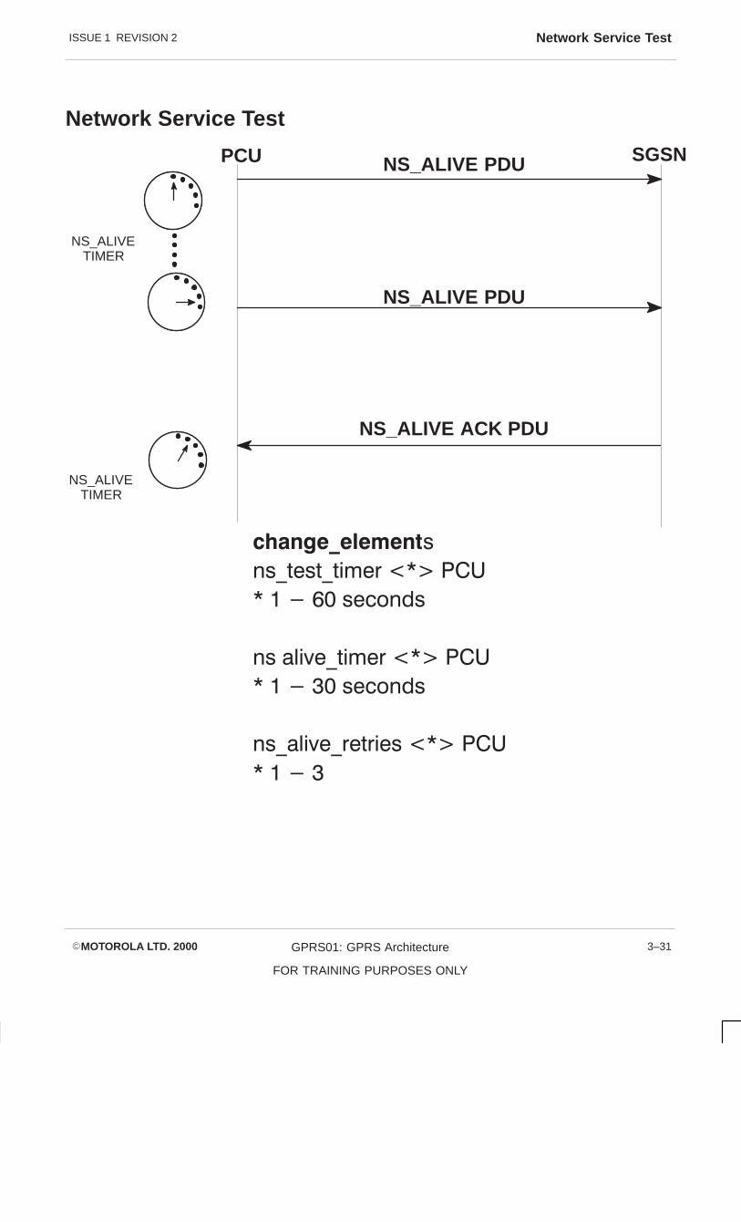
ISSUE 1 REVISION 2 Network Service Test
�MOTOROLA LTD. 2000 GPRS01: GPRS Architecture
FOR TRAINING PURPOSES ONLY
3–31
Network Service Test
PCU SGSNNS_ALIVE PDU
������������� �
�� ���� �������������
���������� ������
�� � ����������������
���������� ������
�� � ������������ ������
�������
NS_ALIVE ACK PDU
NS_ALIVETIMER
NS_ALIVETIMER
NS_ALIVE PDU

ISSUE 1 REVISION 2Network Service
�MOTOROLA LTD. 2000GPRS01: GPRS Architecture
FOR TRAINING PURPOSES ONLY
3–32
Network ServiceThe Network Service performs the transport of NS SDUs between the SGSN and theBSS. The services provided are:
� Network Service SDU transfer
� Network congestion indication
� Status indication
An SGSN and a BSS may use different physical links for connecting to each other. Eachphysical link is locally (at each side of Gb interface) identified by means of a physical linkidentifier.
Each physical link supports one or more Network Service Virtual Links (NS–VL). EachNS–VL is identified by means of a Network Service Virtual Link Identifier. Thesignificance (i.e. local or end to end) depends on the configuration of the Gb interface.The NS_VLI is the association of the Frame Relay DLCI and the bearer channelidentifier.
In order to provide end to end communication between the SGSN and the BSSirrespective of the exact configuration of the Gb interface the Network Service VirtualConnection is used. The NS_VCs are end to end virtual connections between the BSSand the SGSN. At each end of the Gb interface there is a one to one correspondencebetween NS_VCs and NS_VLs. An NS_VC is identified by the means of a NetworkService Virtual Connection Identifier (NS_VCI).
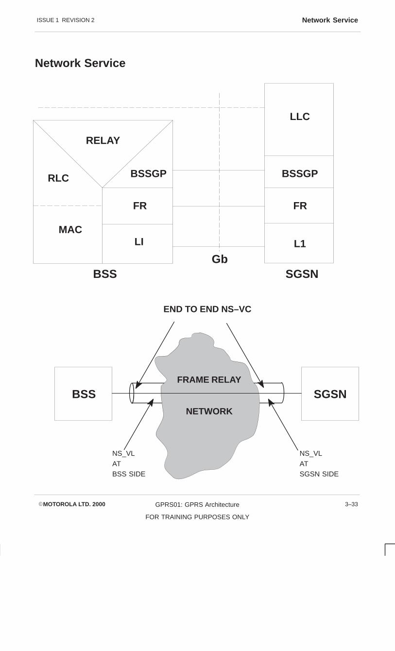
ISSUE 1 REVISION 2 Network Service
�MOTOROLA LTD. 2000 GPRS01: GPRS Architecture
FOR TRAINING PURPOSES ONLY
3–33
Network Service
LLC
BSSGP
FR
L1
RELAY
BSSGP
FR
RLC
MACLI
BSSGb
SGSN
END TO END NS–VC
BSS SGSNFRAME RELAY
NETWORK
NS_VL
ATSGSN SIDE
NS_VL
ATBSS SIDE

ISSUE 1 REVISION 2Network Service Virtual Connection Group
�MOTOROLA LTD. 2000GPRS01: GPRS Architecture
FOR TRAINING PURPOSES ONLY
3–34
Network Service Virtual Connection GroupThe Network Service Virtual Connection Group groups together all the NS_VC providingcommunication between the same peer NS entities.
The network service provides a communication path between remote NS user entities.These communication paths are called BSSGP Virtual Cicuits (BVCs). Each BVC isidentified by a BSSGP Virtual Connection Identifier and is unique amongst all networkelements connected to the SGSN.
Each BVC is supported by one group of NS_VCs. Each group of NS_VCs may supportone or more BVCs.

ISSUE 1 REVISION 2 Network Service Virtual Connection Group
�MOTOROLA LTD. 2000 GPRS01: GPRS Architecture
FOR TRAINING PURPOSES ONLY
3–35
Network Service Virtual Group
BSSGP
NSCONTROL
FR
BSSGP
NSCONTROL
FR
BVCI
NS – VCI
NS – VLI NS – VLI
FRNETWORK

ISSUE 1 REVISION 2Gb Addressing
�MOTOROLA LTD. 2000GPRS01: GPRS Architecture
FOR TRAINING PURPOSES ONLY
3–36
Gb AddressingIn the diagram opposite, an example of two types of Gb interface are shown; anintermediate frame relay network and a point to point frame relay network.
In an intermediate network the Network Service Virtual Link identifier, made up of theDLCI and bearer channel identification, has only local significance. The Network ServiceVirtual Connection Identification has an end to end significance and is part of an NSVCgroup serving a BSSGP Virtual Connection Identification which identifies a cell orsignalling channel for a BSS at both ends of the Gb interface.
In a point to point frame relay network, where the BSS and SGSN are directly connected,the major change is that the DLCI and Bearer Channel identification no longer have localsignificance but have end to end significance.

ISSUE 1 REVISION 2 Gb Addressing
�MOTOROLA LTD. 2000 GPRS01: GPRS Architecture
FOR TRAINING PURPOSES ONLY
3–37
Gb Addressing
BSS #1
BSS #2
PTPCell 1
PTPCell 2
PTPCell 1
Signalling
Signalling
BVC1=2
BVC1=3
NSE1=1
BVC1=0
BVC1=2
BVC1=0
NSE1=2
NS–VC1=a
NS–VC1=b
NS–VC1=c
NS–VC1=d
NS–VC1=e
NS–VC1=f
DLCI=16
DLCI=137
DLCI=51
DLCI=43
DLCI=16
DLCI=259
Bearer Channel = 1
E1
Bearer Channel = 2
E1
Bearer Channel = 3
E1
Bearer Channel = 4
E1
Bea
rer
Cha
nnel
= 5
E1
Bea
rer
Cha
nnel
= 6
E1
DLCI=98
DLCI=17
DLCI=16
DLCI=21
DLCI=302
DLCI=511
NS–VC1=a
NS–VC1=b
NS–VC1=e
NS–VC1=c
NS–VC1=d
NS–VC1=f
SGSN
BVC1=2
BVC1=3
BVC1=0
NSE1=1
BVC1=2
BVC1=0
NSE1=2
FRAME
RELAY
NETWORK

ISSUE 1 REVISION 2Network Service Virtual Connection
�MOTOROLA LTD. 2000GPRS01: GPRS Architecture
FOR TRAINING PURPOSES ONLY
3–38
Network Service Virtual ConnectionThe NSVC command associates an NSVCI to a Network Service Virtual LinkIdentification and also specifies the committed information rate and burst size and burstexcess.
The NSVC must be mapped to a GBL before it can be mapped to an NSVC group orgroups. A DLCI must be unique within a single GBL and may be received within otherGBLs.
Parameter Minimum Maximum
NS_VCI 0 65535
DLCI 16 991
GBL_ID 0 3
An NSVCI is a unique identification between the BSS and SGSN.

ISSUE 1 REVISION 2 Network Service Virtual Connection
�MOTOROLA LTD. 2000 GPRS01: GPRS Architecture
FOR TRAINING PURPOSES ONLY
3–39
Network Service Virtual Connection (NSVC)
add_nsvc <NS_VCI><GBL_ID><DLCI>
Enter the committed Information Rate <*>* 0 –1984 in Kbps
Enter the committed Burst Size <*>* 0 – 1984 in Kbps
Enter the Burst Excess <*>* 0 – 1984 Kbps

ISSUE 1 REVISION 2BSSGP Virtual Circuit Identifier (BVCI)
�MOTOROLA LTD. 2000GPRS01: GPRS Architecture
FOR TRAINING PURPOSES ONLY
3–40
BSSGP Virtual Circuit Identifier (BVCI)The BSSGP Virtual Connection Identifier uniquely identifies a cell within a BSS or asignalling BVCI to that cell. The PCU maintains a table mapping each cell to a uniqueBVCI and all BSSGP signalling such as paging to a separate BVCI.
The BVCI is a new cell element and is included in the prompt for add_cell. A BVCI mustbe unique within a BSS.
Parameter Minimum Maximum Definition
BVCI 2 65535 Specifies the BVCI
A BVCI must be mapped to a cell before a BVCI may be mapped to an NSVC group.
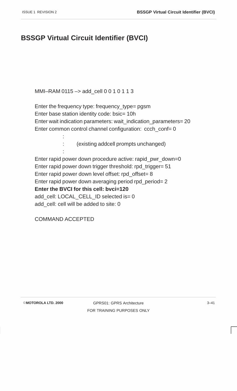
ISSUE 1 REVISION 2 BSSGP Virtual Circuit Identifier (BVCI)
�MOTOROLA LTD. 2000 GPRS01: GPRS Architecture
FOR TRAINING PURPOSES ONLY
3–41
BSSGP Virtual Circuit Identifier (BVCI)
MMI–RAM 0115 –> add_cell 0 0 1 0 1 1 3
Enter the frequency type: frequency_type= pgsmEnter base station identity code: bsic= 10hEnter wait indication parameters: wait_indication_parameters= 20Enter common control channel configuration: ccch_conf= 0
:: (existing addcell prompts unchanged):
Enter rapid power down procedure active: rapid_pwr_down=0Enter rapid power down trigger threshold: rpd_trigger= 51Enter rapid power down level offset: rpd_offset= 8Enter rapid power down averaging period rpd_period= 2Enter the BVCI for this cell: bvci=120add_cell: LOCAL_CELL_ID selected is= 0add_cell: cell will be added to site: 0
COMMAND ACCEPTED

ISSUE 1 REVISION 2GPRS Signalling BVCI
�MOTOROLA LTD. 2000GPRS01: GPRS Architecture
FOR TRAINING PURPOSES ONLY
3–42
GPRS Signalling BVCIThe GB map command allows an NSVC group to be allocated for BSSGP signalling butthe command does not specify the BSSGP Virtual Circuit Identifier (BVCI) identification.Traffic BVCIs are associated with cells and are equipped with add_cell.
To equip a BVCI within a BSS for signalling the element gprs_sig_bvci has been added.This command specifies the unique value for the BVCI for BSSGP signalling.

ISSUE 1 REVISION 2 GPRS Signalling BVCI
�MOTOROLA LTD. 2000 GPRS01: GPRS Architecture
FOR TRAINING PURPOSES ONLY
3–43
SIG BVCI
change _element gprs_sig_bvci <*> PCU
* 0–65535 BVCI identifier

ISSUE 1 REVISION 2Routing Area
�MOTOROLA LTD. 2000GPRS01: GPRS Architecture
FOR TRAINING PURPOSES ONLY
3–44
Routing AreaThe Routing Area is a new definition to allow the separation of the network into routingareas. This has the advantage of allowing the tracking of mobiles within routing areas asa mobile will carry out routing area updates when crossing routing area boundaries. TheRouting Area Code is an additional one byte identifier in the cell identifier of GPRS cellsand is broadcast in System Information message 3.
To allow the mobile to quickly discover if a cell is GPRS enabled and in a different routingarea, Routing Area (RA) colour is used. RA colour has 8 possible variations and isbroadcast in system information message 3, allowing the mobile to quickly identify arouting area boundary and apply the correct response of a routing area update and alsocell reselect hystersis.
The location of an MS in STANDBY state is known in the SGSN on RA level. Thismeans that the mobile is paged in the Routing Area where the MS is located whenmobile terminated packet data arrives at the SGSN. A Routing area is a subset of oneand only one location area.
LAI = MCC + MNC + LAC
RAI = MCC + MNC + LAC + RAC
CGI = LAI + (RAC) + CI
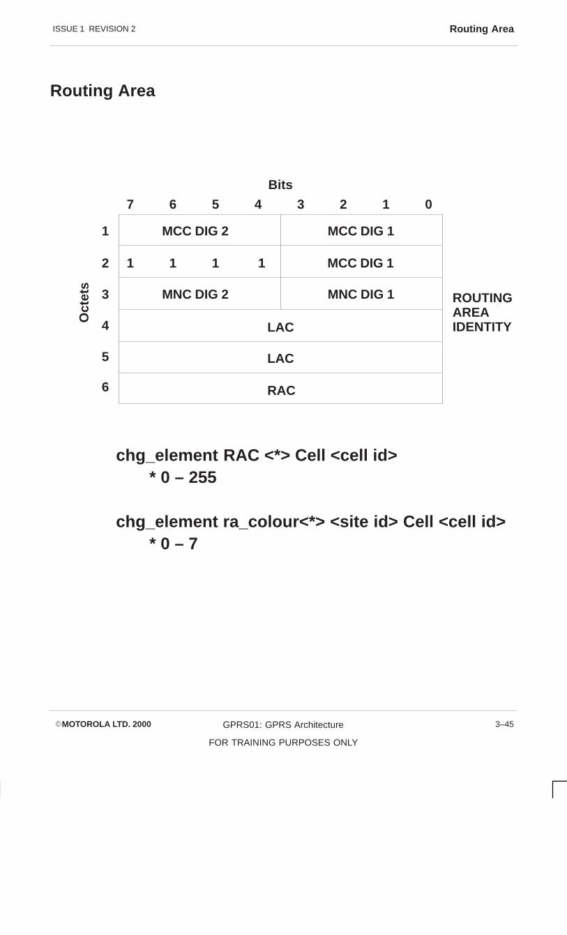
ISSUE 1 REVISION 2 Routing Area
�MOTOROLA LTD. 2000 GPRS01: GPRS Architecture
FOR TRAINING PURPOSES ONLY
3–45
Routing Area
MCC DIG 11
2
6
3
4
5
7 6 5 4 3 2 1 0
MCC DIG 2
1 1 1 1 MCC DIG 1
MNC DIG 1MNC DIG 2
LAC
LAC
RAC
ROUTINGAREAIDENTITY
chg_element RAC <*> Cell <cell id>* 0 – 255
chg_element ra_colour<*> <site id> Cell <cell id>* 0 – 7
Oct
ets
Bits

ISSUE 1 REVISION 2N3102
�MOTOROLA LTD. 2000GPRS01: GPRS Architecture
FOR TRAINING PURPOSES ONLY
3–46
N3102To ensure that a mobile does not continue transmission of an uplink data transfer whenconnection to the network has been lost the counter N3102 and timer T3182 are used.
Every time an uplink ACK/NACK message is received by the mobile the counter N3102is incremented by a value set by gprs_ms_pan_inc up to the maximum ofgprs_ms_pan_max which sets the upper limit of counter N3102.
If the transmit window is stalled as V(S) = V(a) + K (the next RLC/MAC block to be sentis equal to the oldest RLC/MAC block pending acknowledgement, plus the window sizeK). Then the timer T3182 is started and the mobile will retransmit the oldest RLC/MACblock with a NACKED value of the oldest block pending ACK. These blocks aretransmitted with a Stall Indicator set to indicate to the network that the mobile is stalledawaiting an ACK/NACK. If T3182 expires the mobile decrements the counter N3102 bygprs_ms_pan_dec and performs an Abnormal release and then a random access to gainresources to send the uplink.
This condition repeats every time T3132 expires, until N3102 < 0 at which the mobile willperform an abnormal release and a cell reselection.

ISSUE 1 REVISION 2 N3102
�MOTOROLA LTD. 2000 GPRS01: GPRS Architecture
FOR TRAINING PURPOSES ONLY
3–47
N3102
gprs_ms_pan_dec <*><site id> Cell <cell id>* 0 – 7
gprs_ms_pan_inc <*><site id> Cell <cell id>
gprs_ms_pan_max <*> <site id> Cell <cell id>
V(s)= V(a) + K
T3182
gprs_ms_pa_max
N3102

ISSUE 1 REVISION 2N3102
�MOTOROLA LTD. 2000GPRS01: GPRS Architecture
FOR TRAINING PURPOSES ONLY
3–48

�MOTOROLA LTD. 2000 GPRS01: GPRS Architecture
FOR TRAINING PURPOSES ONLY
i
Chapter 4
PCU Statistics Application

ISSUE 1 REVISION 2
�MOTOROLA LTD. 2000GPRS01: GPRS Architecture
FOR TRAINING PURPOSES ONLY
ii

ISSUE 1 REVISION 2
�MOTOROLA LTD. 2000 GPRS01: GPRS Architecture
FOR TRAINING PURPOSES ONLY
iii
Chapter 4PCU Statistics Application i. . . . . . . . . . . . . . . . . . . . . . . . . . . . . . . . . . . . . . . . . . .
PCU Statistics Application 4–1. . . . . . . . . . . . . . . . . . . . . . . . . . . . . . . . . . . . . . . . . . . . . . . . . . . Objectives 4–1. . . . . . . . . . . . . . . . . . . . . . . . . . . . . . . . . . . . . . . . . . . . . . . . . . . . . . . . . . .
GPRS Performance Measurements 4–2. . . . . . . . . . . . . . . . . . . . . . . . . . . . . . . . . . . . . . . . . . . Introduction to GPRS performance statistics 4–2. . . . . . . . . . . . . . . . . . . . . . . . . . . . . . Description of Gb interface 4–2. . . . . . . . . . . . . . . . . . . . . . . . . . . . . . . . . . . . . . . . . . . . . GBL statistics 4–2. . . . . . . . . . . . . . . . . . . . . . . . . . . . . . . . . . . . . . . . . . . . . . . . . . . . . . . . . Description of accessibility statistics 4–3. . . . . . . . . . . . . . . . . . . . . . . . . . . . . . . . . . . . . Accessibility statistics 4–3. . . . . . . . . . . . . . . . . . . . . . . . . . . . . . . . . . . . . . . . . . . . . . . . . . Throughput statistics 4–3. . . . . . . . . . . . . . . . . . . . . . . . . . . . . . . . . . . . . . . . . . . . . . . . . . Dynamic allocation statistics 4–3. . . . . . . . . . . . . . . . . . . . . . . . . . . . . . . . . . . . . . . . . . . .
GBL Statistic Diagrams 4–4. . . . . . . . . . . . . . . . . . . . . . . . . . . . . . . . . . . . . . . . . . . . . . . . . . . . . .
GBL_DL_DATA_THRPUT 4–9. . . . . . . . . . . . . . . . . . . . . . . . . . . . . . . . . . . . . . . . . . . . . . . . . . .
GBL_DL_DATA_THRPUT_HIST 4–10. . . . . . . . . . . . . . . . . . . . . . . . . . . . . . . . . . . . . . . . . . . . . .
GBL_FLOW_CTRL_SENT 4–11. . . . . . . . . . . . . . . . . . . . . . . . . . . . . . . . . . . . . . . . . . . . . . . . . . .
GBL_FLUSH_REQS 4–12. . . . . . . . . . . . . . . . . . . . . . . . . . . . . . . . . . . . . . . . . . . . . . . . . . . . . . . .
GBL_LINK_INS 4–13. . . . . . . . . . . . . . . . . . . . . . . . . . . . . . . . . . . . . . . . . . . . . . . . . . . . . . . . . . . .
GBL_PAGING_REQS 4–14. . . . . . . . . . . . . . . . . . . . . . . . . . . . . . . . . . . . . . . . . . . . . . . . . . . . . . .
GBL_UL_DATA_THRPUT 4–15. . . . . . . . . . . . . . . . . . . . . . . . . . . . . . . . . . . . . . . . . . . . . . . . . . .
GBL_UL_DATA_THRPUT_HIST 4–16. . . . . . . . . . . . . . . . . . . . . . . . . . . . . . . . . . . . . . . . . . . . . .
GBL_UNAVAILABLE 4–17. . . . . . . . . . . . . . . . . . . . . . . . . . . . . . . . . . . . . . . . . . . . . . . . . . . . . . . .
Accessibility Statistic Diagrams 4–18. . . . . . . . . . . . . . . . . . . . . . . . . . . . . . . . . . . . . . . . . . . . . . .
CHANNEL_REQS_REC 4–23. . . . . . . . . . . . . . . . . . . . . . . . . . . . . . . . . . . . . . . . . . . . . . . . . . . . .
CHANNEL_REQS_REJECT 4–24. . . . . . . . . . . . . . . . . . . . . . . . . . . . . . . . . . . . . . . . . . . . . . . . .
GPRS_ACCESS_PER_AGCH 4–25. . . . . . . . . . . . . . . . . . . . . . . . . . . . . . . . . . . . . . . . . . . . . . .
GPRS_ACCESS_PER_PCH 4–26. . . . . . . . . . . . . . . . . . . . . . . . . . . . . . . . . . . . . . . . . . . . . . . . .
GPRS_ACCESS_PER_RACH 4–27. . . . . . . . . . . . . . . . . . . . . . . . . . . . . . . . . . . . . . . . . . . . . . . .
GPRS_CHANNELS_SWITCHED 4–28. . . . . . . . . . . . . . . . . . . . . . . . . . . . . . . . . . . . . . . . . . . . .
MS_CLASS_1_10_REQ 4–29. . . . . . . . . . . . . . . . . . . . . . . . . . . . . . . . . . . . . . . . . . . . . . . . . . . . .
MS_CLASS_11_20_REQ 4–30. . . . . . . . . . . . . . . . . . . . . . . . . . . . . . . . . . . . . . . . . . . . . . . . . . . .
MS_CLASS_21_29_REQ 4–31. . . . . . . . . . . . . . . . . . . . . . . . . . . . . . . . . . . . . . . . . . . . . . . . . . . .
Throughput Statistic Diagrams 4–33. . . . . . . . . . . . . . . . . . . . . . . . . . . . . . . . . . . . . . . . . . . . . . . .
AIR_DL_DATA_BLKS 4–37. . . . . . . . . . . . . . . . . . . . . . . . . . . . . . . . . . . . . . . . . . . . . . . . . . . . . . .
AIR_UL_DATA_BLKS 4–38. . . . . . . . . . . . . . . . . . . . . . . . . . . . . . . . . . . . . . . . . . . . . . . . . . . . . . .
DL_CHAN_ASGN_DURATION 4–39. . . . . . . . . . . . . . . . . . . . . . . . . . . . . . . . . . . . . . . . . . . . . . .
TOTAL_AIR_DL_AVAILABLE_BW 4–40. . . . . . . . . . . . . . . . . . . . . . . . . . . . . . . . . . . . . . . . . . . .
TOTAL_AIR_UL_AVAILABLE_BW 4–41. . . . . . . . . . . . . . . . . . . . . . . . . . . . . . . . . . . . . . . . . . . .
UL_CHAN_ASGN_DURATION 4–42. . . . . . . . . . . . . . . . . . . . . . . . . . . . . . . . . . . . . . . . . . . . . . .

ISSUE 1 REVISION 2
�MOTOROLA LTD. 2000GPRS01: GPRS Architecture
FOR TRAINING PURPOSES ONLY
iv

ISSUE 1 REVISION 2 PCU Statistics Application
�MOTOROLA LTD. 2000 GPRS01: GPRS Architecture
FOR TRAINING PURPOSES ONLY
4–1
PCU Statistics Application
Objectives
On completion of this chapter the student will be able to:
� Understand the meaning of each Statistic pegged at the PCU.

ISSUE 1 REVISION 2GPRS Performance Measurements
�MOTOROLA LTD. 2000GPRS01: GPRS Architecture
FOR TRAINING PURPOSES ONLY
4–2
GPRS Performance Measurements
Introduction toGPRSperformancestatistics
This chapter includes descriptions of the General Packet Radio Service (GPRS)statistics. GPRS statistics are organized in the following groups:
� Gb link (GBL) statistics.
� Accessibility statistics.
� Throughput statistics.
� Dynamic allocation statistics.
Description ofGb interface
The GBL device refers to the configured number of timeslots on an E1 span between thePacket Control Unit (PCU) and the Serving GPRS Support Node (SGSN). This interfaceis referred to as the Gb interface. The Gb interface allows many users to be multiplexedover a common physical resource. GPRS signalling and user data are sent on the samephysical resource. That is, no dedicated physical resources are required to be allocatedfor signalling purposes.
GBL statistics
The GBL measurement types are listed as follows:
� GBL_DL_DATA_THRPUT
� GBL_DL_DATA_THRPUT_HIST
� GBL_FLOW_CTRL_SENT
� GBL_FLUSH_REQS
� GBL_LINK_INS
� GBL_PAGING_REQS
� GBL_UL_DATA_THRPUT
� GBL_UL_DATA_THRUT_HIST
� GBL_UNAVAILABLE

ISSUE 1 REVISION 2 GPRS Performance Measurements
�MOTOROLA LTD. 2000 GPRS01: GPRS Architecture
FOR TRAINING PURPOSES ONLY
4–3
Description ofaccessibilitystatistics
Accessiblility statistics are used to measure how effectively GPRS resources are beingaccessed. These measurements are used to assist the operator in planning thenecessary resources needed for the mobile to efficiently access the network.
Accessibilitystatistics
The accessiblility statistics are listed as follows:
� CHANNEL_REQS_REC
� CHANNEL_REQS_REJECT
� DL_CHAN_ASGN_DURATION
� GPRS_ACCESS_PER_AGCH
� GPRS_ACCESS_PER_PCH
� GPRS_ACCESS_PER_RACH
� GPRS_CHANNELS_SWITCHED
� UL_CHAN_ASGN_DURATION
Throughputstatistics
The throughput statistics are listed as follows:
� AIR_UL_DATA_BLKS
� AIR_DL_DATA_BLKS
� DL_CHAN_ASGN_DURATION
� GBL_DL_DATA_THRPUT
� GBL_DL_DATA_THRPUT_HIST
� GBL_UL_DATA_THRPUT
� GBL_UL_DATA_THRPUT_HIST
� TOTAL_AIR_UL_AVAILABLE_BW
� TOTAL_AIR_DL_AVAILABLE_BW
� UL_CHAN_ASGN_DURATION
Dynamicallocationstatistics
The dynamic allocation statistics are listed as follows:
� GPRS_DYNET_FAILURES
� GPRS_DYNET_RES_REQS
� GPRS_DYNET_SWI_REQS


ISSUE 1 REVISION 2GBL Statistic Diagrams
�MOTOROLA LTD. 2000GPRS01: GPRS Architecture
FOR TRAINING PURPOSES ONLY
4–4
GBL Statistic DiagramsFigure 4-1 to Figure 4-5 show how the GBL statistics function within the BSS/PCU.
GBL_DL_DATA_THRPUT
GBL_DL_DATA_THRPUT_TIME_PERIOD
Bearer chan 1
DLCI = 45
DLCI = 55
DLCI = 45
DLCI = 55
Figure 4-1 GBL_DL_DATA_THRPUT

ISSUE 1 REVISION 2 GBL Statistic Diagrams
�MOTOROLA LTD. 2000 GPRS01: GPRS Architecture
FOR TRAINING PURPOSES ONLY
4–5
Figure 4-2 is a ladder diagram detailing the statistic gbl_flow_ctrl_sent when it ispegged. It also shows the request and the response messages sent from the BSS/PCUto the SGSN.
BSSGP FLOW CONTROL PDU
BSSGP FLOW CONTROL ACK PDU
BSS/PCU SGSN
GBL_FLOW_CTRL_SENT
Figure 4-2 GBL_FLOW_CTRL_SENT
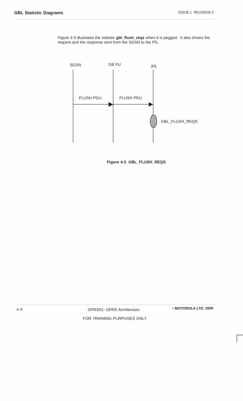
ISSUE 1 REVISION 2GBL Statistic Diagrams
�MOTOROLA LTD. 2000GPRS01: GPRS Architecture
FOR TRAINING PURPOSES ONLY
4–6
Figure 4-3 illustrates the statistic gbl_flush_reqs when it is pegged. It also shows therequest and the response sent from the SGSN to the PS.
FLUSH PDU FLUSH PDU
SGSN GB FU PS
GBL_FLUSH_REQS
Figure 4-3 GBL_FLUSH_REQS

ISSUE 1 REVISION 2 GBL Statistic Diagrams
�MOTOROLA LTD. 2000 GPRS01: GPRS Architecture
FOR TRAINING PURPOSES ONLY
4–7
Figure 4-4 is a ladder diagram detailing the statistic gbl_paging_reqs when it is pegged.It also shows the request and the response messages sent from the SGSN to theBSS/PCU and the mobile station.
MSBSS/PCU
Channel Request (RACH)
Immediate Assignment (AGCH)
SGSN
BSSGP PS PDU
GBL_PAGING_REQS
PACKET PAGING REQEST (PCH)
Figure 4-4 GBL_PAGING_REQS

ISSUE 1 REVISION 2GBL Statistic Diagrams
�MOTOROLA LTD. 2000GPRS01: GPRS Architecture
FOR TRAINING PURPOSES ONLY
4–8
Figure 4-5 illustrates the statistic gbl_ul_data_thrput .
GBL_UL_DATA_THRPUT
GBL_UL_DATA_THRPUT_TIME_PERIOD
Bearer chan 1
DLCI = 45
DLCI = 55
DLCI = 45
DLCI = 55
Figure 4-5 GBL_UL_DATA_THRPUT

ISSUE 1 REVISION 2 GBL_DL_DATA_THRPUT
�MOTOROLA LTD. 2000 GPRS01: GPRS Architecture
FOR TRAINING PURPOSES ONLY
4–9
GBL_DL_DATA_THRPUT
Description
This statistic measures the number of megabits transmitted on the downlink Gb link(GBL) for a given period of time. The Packet Control Unit (PCU) will then calculate theinstantaneous throughput by dividing the number of megabits received in the timeinterval. The time interval gbl_dl_thrput_time_period will be programmable.
The PCU will filter this statistic by computing a moving average of the instantaneousthroughput. The number of instantaneous throughput samplesnum_gbl_dl_data_thrput_samples used to compute the moving average will also beprogrammable.
Refer to Figure 4-5 for an illustration of this statistic.
Pegging
This statistic is pegged by calculating the number of megabits received by the PCUduring the interval, gbl_dl_thrput_time_period .
Analysis
This statistic can be used for the trend analysis of the average downlink throughput of theGBL.
Reference None.
Usage Network planning.
Congestion.
Basis GBL
Type Gauge.

ISSUE 1 REVISION 2GBL_DL_DATA_THRPUT_HIST
�MOTOROLA LTD. 2000GPRS01: GPRS Architecture
FOR TRAINING PURPOSES ONLY
4–10
GBL_DL_DATA_THRPUT_HIST
Description
This statistic is a histogram of the total downlink data throughput on the GBL for ameasurement period at the PCU.
The number of bins in the histogram is 10 and the ranges are programmable shown inTable 4-1.
Table 4-1 GBL_DL_DATA_THRPUT_HIST bins 0 – 600
Bin Range
0 0 – 30
1 31 – 71
2 71 – 110
3 111 – 140
4 141 – 170
5 171 – 230
6 231 – 300
7 301 – 400
8 401 – 500
9 501 – 600
Pegging
This statistic is pegged by calculating the number of megabits transmitted by the PCUduring the interval gbl_dl_thrput_time_period .
Analysis
This statistic can be used for the trend analysis of GBL downlink throughput.
Reference None.
Usage Network planning.
Congestion.
Quality of service monitoring: Networkaccessibility.
Basis GBL.
Type Normal Distribution.

ISSUE 1 REVISION 2 GBL_FLOW_CTRL_SENT
�MOTOROLA LTD. 2000 GPRS01: GPRS Architecture
FOR TRAINING PURPOSES ONLY
4–11
GBL_FLOW_CTRL_SENT
Description
This statistic indicates the number of flow control messages sent by the BSS to theServing GPRS Support Node (SGSN).
Each cell has a buffer that holds downlink data. When a cell buffer reaches apredetermined threshold, a flow control message is sent to the SGSN.
Flow control is performed to match the flow of downlink data with air throughput.
Refer to Figure 4-2 for an illustration of this statistic.
Pegging
This statistic pegs the number of flow control messages sent by the BSS and is peggedevery time a flow control message is sent.
Analysis
This statistic can be used for trend analysis of the number of flow control messages sentby the BSS.
Reference None.
Usage Network planning.
Congestion.
Quality of service monitoring: Networkaccessibility.
Basis Cell.
Type Counter.

ISSUE 1 REVISION 2GBL_FLUSH_REQS
�MOTOROLA LTD. 2000GPRS01: GPRS Architecture
FOR TRAINING PURPOSES ONLY
4–12
GBL_FLUSH_REQS
Description
This statistic counts the number of flush requests received on the GBL.
Refer to Figure 4-3 for an illustration of this statistic.
Pegging
This statistic is pegged each time a flush request is received on the GBL to flush theLogical Link Control (LLC) Protocol Data Unit (PDU) for a particular mobile station.
Analysis
This statistic can be used for the trend analysis of the number of flushable messagesreceived by the BSS.
Reference None.
Usage Network planning.
Congestion.
Basis BSS.
Type Counter.

ISSUE 1 REVISION 2 GBL_LINK_INS
�MOTOROLA LTD. 2000 GPRS01: GPRS Architecture
FOR TRAINING PURPOSES ONLY
4–13
GBL_LINK_INS
Description
This duration statistic will be started by the GPRS PCU each time the GBL becomes inservice (INS). The statistic GBL_LINK_INS willl stop each time the GBL has gone out ofservice.
The time available for this statistic will be reported in milliseconds.
Pegging
The timer for this statistic will start once the GBL transitions to the B-U state. The timerfor this statistic will stop once the GBL is no longer in the B-U state.
Analysis
This statistic can be used for trend analysis of the utilization of in-service GBL.
Reference None.
Usage Network accessibility
Fault finding.
Protocol utiliztion.
Basis GBL.
Type Duration.

ISSUE 1 REVISION 2GBL_PAGING_REQS
�MOTOROLA LTD. 2000GPRS01: GPRS Architecture
FOR TRAINING PURPOSES ONLY
4–14
GBL_PAGING_REQS
Description
This statistic counts the number of paging requests received on the GBL.
Refer to Figure 4-4 and Figure 4-8 for an illustration of this statistic.
Pegging
This statistic is pegged each time a page request is received on the GBL to page amobile.
Analysis
This statistic can be used for the trend analysis of the number of circuit switched andpacket switched pages received by the BSS from the SGSN.
Reference None.
Usage Network planning.
Congestion.
Basis BSS.
Type Counter.

ISSUE 1 REVISION 2 GBL_UL_DATA_THRPUT
�MOTOROLA LTD. 2000 GPRS01: GPRS Architecture
FOR TRAINING PURPOSES ONLY
4–15
GBL_UL_DATA_THRPUT
Description
This statistic measures the number of kilobits of data information transmitted on theuplink of the GBL for a given period of time. The PCU will then calculate theinstantaneous throughput by dividing the number of megabits transmitted by the timeinterval.
The time interval gbl_ul_thrput_period will be programmable. The PCU will filter thisstatistic by computing a moving average of the instantaneous throughput. The number ofinstantaneous throughput samples num_gbl_ul_thrput_samples used to compute themoving average will also be programmable.
Refer to Figure 4-5 for an illustration of this statistic.
Pegging
This statistic is pegged by calculating the number of megabits received by the PCUduring the interval, gbl_ul_thrput_period .
The number of bins in the histogram is 10 and the ranges are programmable shown inTable 4-2.
Table 4-2 GBL_UL_DATA_THRPUT_HIST bins 0 – 600
Bin Range
0 0 – 30
1 31 – 71
2 71 – 110
3 111 – 140
4 141 – 170
5 171 – 230
6 231 – 300
7 301 – 400
8 401 – 500
9 501 – 600
Analysis
This statistic can be used for the trend analysis of the average uplink throughput of theGBL.
Reference None.
Usage Network planning.
Congestion.
Basis GBL.
Type Gauge.

ISSUE 1 REVISION 2GBL_UL_DATA_THRPUT_HIST
�MOTOROLA LTD. 2000GPRS01: GPRS Architecture
FOR TRAINING PURPOSES ONLY
4–16
GBL_UL_DATA_THRPUT_HIST
Description
This statistic is a histogram of the total uplink data throughput on the GBL for ameasurement period at the PCU.
The number of bins in the histogram is 10 and the ranges are programmable.
Pegging
This statistic is pegged by calculating the number of megabits transmitted by the PCUduring the interval gbl_ul_thrput_time_period .
Analysis
This statistic can be used for the trend analysis of GBL uplink throughput.
Reference None.
Usage Network planning.
Congestion.
Quality of service monitoring: Networkaccessiblility.
Basis GBL.
Type Normal Distribution.

ISSUE 1 REVISION 2 GBL_UNAVAILABLE
�MOTOROLA LTD. 2000 GPRS01: GPRS Architecture
FOR TRAINING PURPOSES ONLY
4–17
GBL_UNAVAILABLE
Description
This statistic is the duration that the GBL is out of service. This statistic will stop whenthe GBL becomes in service.
The available time will be reported in milliseconds.
Pegging
The timer for this statistic is started when the GBL transitions to a state which is not B-U.It is stopped when the GBL is in the B-U state.
Analysis
This statistic can be used for trend analysis of the duration of GBL outages, includingthose caused by operator interaction.
Reference None.
Usage Network accessibility.
Fault finding.
Basis GBL.
Type Duration.


ISSUE 1 REVISION 2Accessibility Statistic Diagrams
�MOTOROLA LTD. 2000GPRS01: GPRS Architecture
FOR TRAINING PURPOSES ONLY
4–18
Accessibility Statistic DiagramsFigure 4-6 is a ladder diagram detailing the statistic channel_req_rej when it is pegged.It also shows the request and the response messages sent from the BSS/PCU to themobile station.
Immediate Assignment (AGCH)
MSBSS/PCU
Packet Resource Request
CHANNEL_REQ_REJ
PACKET ACESS REJECT
Figure 4-6 Accessibility CHANNEL_REQ_REJ

ISSUE 1 REVISION 2 Accessibility Statistic Diagrams
�MOTOROLA LTD. 2000 GPRS01: GPRS Architecture
FOR TRAINING PURPOSES ONLY
4–19
Figure 4-7 is a ladder diagram detailing the statistics gprs_access_per_rach andgprs_access_per_agch when pegging occurs. It also shows the request and theresponse messages sent from the BSS/PCU to the mobile station.
MSBSS/PCU
Channel Request (RACH)
GPRS_ACCESS_PER_RACH
GPRS_ACCESS_PER_AGCH
Immediate Assignment (AGCH)
Figure 4-7 GPRS_ACCESS_PER_RACH and GPRS_ACCESS_PER_AGCH

ISSUE 1 REVISION 2Accessibility Statistic Diagrams
�MOTOROLA LTD. 2000GPRS01: GPRS Architecture
FOR TRAINING PURPOSES ONLY
4–20
Figure 4-8 is a ladder diagram detailing the statistics gbl_paging_reqs ,gprs_access_per_pch , gprs_access_per_rach , and gprs_access_per_agch whenpegging occurs. It also shows the request and response messages sent from the SGSNto the BSS/PCU and to the mobile station.
MSBSS/PCU
Channel Request (RACH)
GPRS_ACCESS_PER_RACH
GPRS_ACCESS_PER_AGCH
Immediate Assignment (AGCH)
SGSN
BSSGP PS PDU
GBL_PAGING_REQS
GPRS_ACCESS_PER_PCH
PACKET PAGING REQEST (PCH)
Figure 4-8 Accessiblility and GBL statistics

ISSUE 1 REVISION 2 Accessibility Statistic Diagrams
�MOTOROLA LTD. 2000 GPRS01: GPRS Architecture
FOR TRAINING PURPOSES ONLY
4–21
Figure 4-9 is a ladder diagram detailing three MS class type statistics and when peggingoccurs. It also shows the request and response messages sent from the BSS/PCU tothe mobile station.
Immediate Assignment (AGCH)
MSBSS/PCU
Packet Resource Request
MS_CLASS_1_10_REQ
MS_CLASS_11_20_REQ
MS_CLASS_21_29_REQ
CHANNEL_REQ_REC
Figure 4-9 MS CLASS Statistics
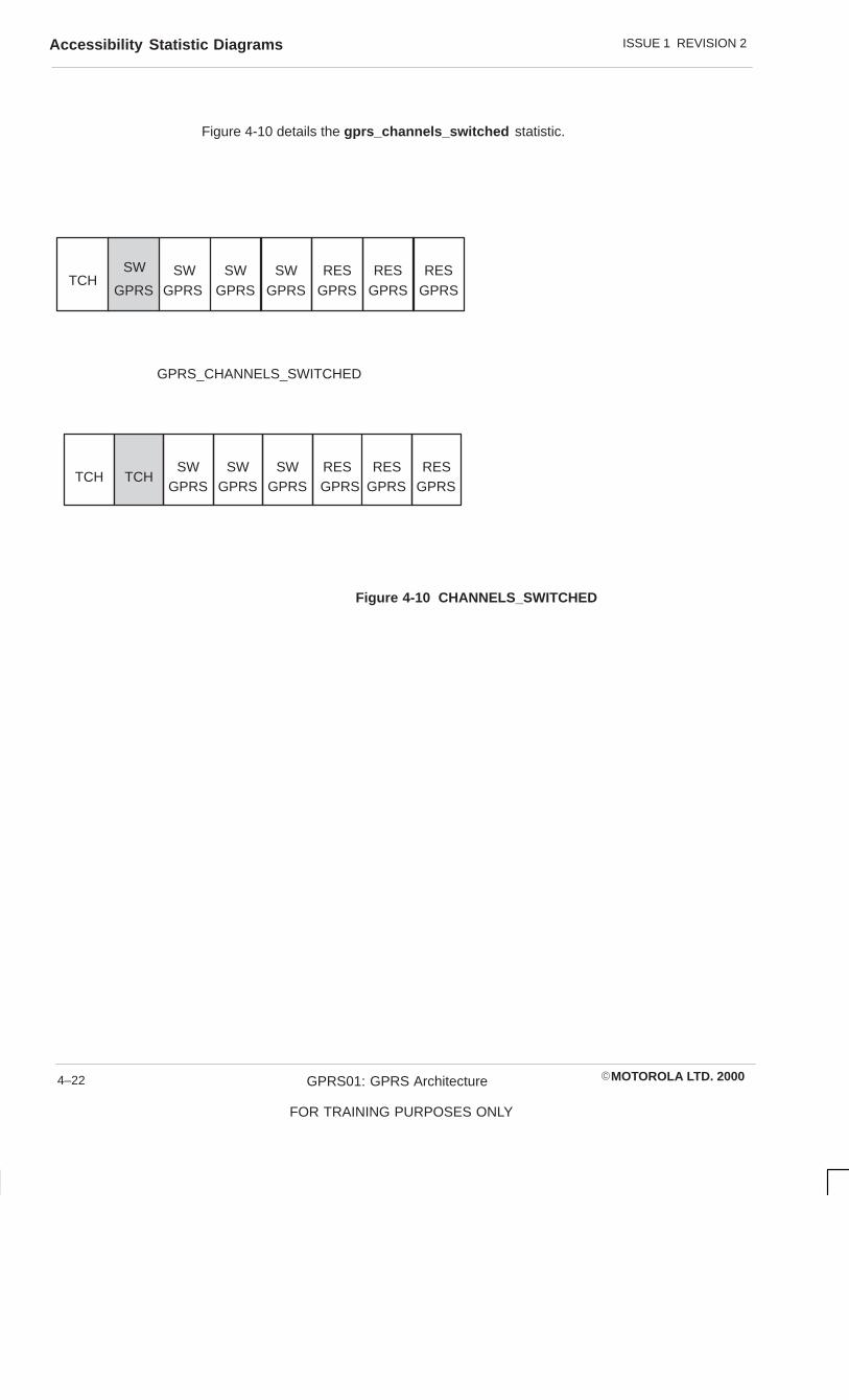
ISSUE 1 REVISION 2Accessibility Statistic Diagrams
�MOTOROLA LTD. 2000GPRS01: GPRS Architecture
FOR TRAINING PURPOSES ONLY
4–22
Figure 4-10 details the gprs_channels_switched statistic.
TCHSW
GPRSRESSW
GPRSRESSW
GPRSSW RES
TCHSW RES
TCHRESSW
GPRSSW RES
GPRS_CHANNELS_SWITCHED
GPRS GPRS GPRSGPRS
GPRS GPRS GPRSGPRS GPRS
Figure 4-10 CHANNELS_SWITCHED

ISSUE 1 REVISION 2 CHANNEL_REQS_REC
�MOTOROLA LTD. 2000 GPRS01: GPRS Architecture
FOR TRAINING PURPOSES ONLY
4–23
CHANNEL_REQS_REC
Description
This statistic counts the number of channel or resource request messages received bythe Packet Control Unit (PCU).
Refer to Figure 4-9 for an illustration of this statistic.
Pegging
This statistic pegs for each channel request message received by the PCU.
Analysis
Reference None.
Usage Network planning.
Basis Cell.
Type Counter.

ISSUE 1 REVISION 2CHANNEL_REQS_REJECT
�MOTOROLA LTD. 2000GPRS01: GPRS Architecture
FOR TRAINING PURPOSES ONLY
4–24
CHANNEL_REQS_REJECT
Description
This statistic measures the number of packet channel or resource request received bythe PCU that were rejected.
Refer to Figure 4-6 for an illustration of this statistic.
Pegging
This statistic is pegged when an immediate assignment reject message is sent to the MSin response to a packet channel or resource request. This is due to no channels beingavailable to be allocated.
Analysis
Reference None.
Usage Network planning.
Congestion.
Basis Cell.
Type Counter.

ISSUE 1 REVISION 2 GPRS_ACCESS_PER_AGCH
�MOTOROLA LTD. 2000 GPRS01: GPRS Architecture
FOR TRAINING PURPOSES ONLY
4–25
GPRS_ACCESS_PER_AGCH
Description
This statistic counts the Immediate Assignment messages sent on the Access GrantChannel (AGCH) of a cell for packet data service.
The air interface message on the AGCH for packet immediate assignment andimmediate assignment reject, will contain only on MS.
Access Grants for more than one MS may be contained in one Access Grant message.An Access Grant for more than one MS is only pegged once. This count includesImmediate Assignment, Immediate Extended, and Immediate Assignment Rejectmessages sent on the AGCH of a cell.
Refer to Figure 4-7 and Figure 4-8 for an illustration of this statistic.
Pegging
This statistic is pegged when an access grant message is sent on the AGCH on a cell forpacket data service.
Analysis
This statistic can be used for trend analysis of Immediate Assignment messages sent onthe AGCH of a cell.
Reference None.
Usage Radio resource allocation statistics.
Network planning.
Basis Cell.
Type Counter.

ISSUE 1 REVISION 2GPRS_ACCESS_PER_PCH
�MOTOROLA LTD. 2000GPRS01: GPRS Architecture
FOR TRAINING PURPOSES ONLY
4–26
GPRS_ACCESS_PER_PCH
Description
This statistic counts Paging Request messages sent on the Paging Channel (PCH) of acell for GPRS mobiles.
Pages for circuit switch and packet switch MS can be combined in on PCH message.
Refer to Figure 4-8 for an illustration of this statistic.
Pegging
This statistic is pegged when at least one general packet radio system (GPRS) mobile iscontained in the message sent over the PCH.
Analysis
This statistic can be used for trend analysis of paging request messages sent on thePCH of a cell for packet and GPRS mobile system.
Reference None.
Usage Radio resource allocation statistics.
Network planning.
Basis Cell.
Type Counter.

ISSUE 1 REVISION 2 GPRS_ACCESS_PER_RACH
�MOTOROLA LTD. 2000 GPRS01: GPRS Architecture
FOR TRAINING PURPOSES ONLY
4–27
GPRS_ACCESS_PER_RACH
Description
This statistic counts Channel Request messages sent on the Random Access Channel(RACH) of a cell.
Pegging
Refer to Figure 4-7 and Figure 4-8 for an illustration of this statistic.
Analysis
This statistic can be used for trend analysis of Immediate Assignment messages sent onthe RACH of a cell.
Reference None.
Usage Radio resource allocation statistics.
Network planning.
Basis Cell.
Type Counter.

ISSUE 1 REVISION 2GPRS_CHANNELS_SWITCHED
�MOTOROLA LTD. 2000GPRS01: GPRS Architecture
FOR TRAINING PURPOSES ONLY
4–28
GPRS_CHANNELS_SWITCHED
Description
This statistic counts the number of times that a Packet Data Traffic Channel (PDTCH) isswitched to a Traffic Channel (TCH).
Refer to Figure 4-10 for an illustration for this statistic.
Pegging
This statistic will be incremented each time a PDTCH is switched to a TCH or when aTCH is switched to a PDTCH.
Analysis
Reference None.
Usage
Basis Cell.
Type Counter.

ISSUE 1 REVISION 2 MS_CLASS_1_10_REQ
�MOTOROLA LTD. 2000 GPRS01: GPRS Architecture
FOR TRAINING PURPOSES ONLY
4–29
MS_CLASS_1_10_REQ
Description
This counter array statistic tracks the number of requests received for the mobile stationclasses 1 through 10.
Refer to Figure 4-9 for an illustration of this statistic.
The units of each bin are 10 requests shown in Table 4-3.
Table 4-3 MS_CLASS_1_10_REQ bins 1 through 10
Bin Scenario Description
0 MS_CLASS_1_REQ Number of requests for class 1
1 MS_CLASS_2_REQ Number of requests for class 2
2 MS_CLASS_3_REQ Number of requests for class 3
3 MS_CLASS_4_REQ Number of requests for class 4
4 MS_CLASS_5_REQ Number of requests for class 5
5 MS_CLASS_6_REQ Number of requests for class 6
6 MS_CLASS_7_REQ Number of requests for class 7
7 MS_CLASS_8_REQ Number of requests for class 8
8 MS_CLASS_9_REQ Number of requests for class 9
9 MS_CLASS_10_REQ Number of requests for class 10
Pegging
This is one of three stats that is pegged every time there is an uplink request from anMS. The other two are MS_CLASS_11_19_REQ and MS_CLASS_20_29_REQ .
Analysis
Reference GSM 05.02, 6.2.0, Annex B.
Usage Network planning.
Basis Cell.
Type Counter array.
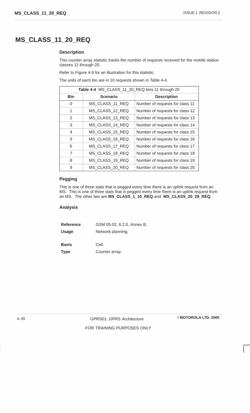
ISSUE 1 REVISION 2MS_CLASS_11_20_REQ
�MOTOROLA LTD. 2000GPRS01: GPRS Architecture
FOR TRAINING PURPOSES ONLY
4–30
MS_CLASS_11_20_REQ
Description
This counter array statistic tracks the number of requests received for the mobile stationclasses 11 through 20.
Refer to Figure 4-9 for an illustration for this statistic.
The units of each bin are in 10 requests shown in Table 4-4.
Table 4-4 MS_CLASS_11_20_REQ bins 11 through 20
Bin Scenario Description
0 MS_CLASS_11_REQ Number of requests for class 11
1 MS_CLASS_12_REQ Number of requests for class 12
2 MS_CLASS_13_REQ Number of requests for class 13
3 MS_CLASS_14_REQ Number of requests for class 14
4 MS_CLASS_15_REQ Number of requests for class 15
5 MS_CLASS_16_REQ Number of requests for class 16
6 MS_CLASS_17_REQ Number of requests for class 17
7 MS_CLASS_18_REQ Number of requests for class 18
8 MS_CLASS_19_REQ Number of requests for class 19
9 MS_CLASS_20_REQ Number of requests for class 20
Pegging
This is one of three stats that is pegged every time there is an uplink request from anMS. This is one of three stats that is pegged every time there is an uplink request froman MS. The other two are MS_CLASS_1_10_REQ and MS_CLASS_20_29_REQ .
Analysis
Reference GSM 05.02, 6.2.0, Annex B.
Usage Network planning.
Basis Cell.
Type Counter array.

ISSUE 1 REVISION 2 MS_CLASS_21_29_REQ
�MOTOROLA LTD. 2000 GPRS01: GPRS Architecture
FOR TRAINING PURPOSES ONLY
4–31
MS_CLASS_21_29_REQ
Description
This counter array statistic tracks the number of requests received for the mobile stationclasses 21 through 29.
Refer to Figure 4-9 for an illustration for this statistic.
The units of each bin are in 10 requests shown in Table 4-5.
Table 4-5 MS_CLASS_21_29_REQ bins 21 through 29
Bin Scenario Description
0 MS_CLASS_21_REQ Number of requests for class 21
1 MS_CLASS_22_REQ Number of requests for class 22
2 MS_CLASS_23_REQ Number of requests for class 23
3 MS_CLASS_24_REQ Number of requests for class 24
4 MS_CLASS_25_REQ Number of requests for class 25
5 MS_CLASS_26_REQ Number of requests for class 26
6 MS_CLASS_27_REQ Number of requests for class 27
7 MS_CLASS_28_REQ Number of requests for class 28
8 MS_CLASS_29_REQ Number of requests for class 29
Pegging
This is one of three stats that is pegged every time there is an uplink request from anMS. This is one of three stats that is pegged every time there is an uplink request froman MS. The other two are MS_CLASS_1_10_REQ and MS_CLASS_11_19_REQ .
Analysis
Reference GSM 05.02, 6.2.0, Annex B.
Usage Network planning.
Basis Cell.
Type Counter array.

ISSUE 1 REVISION 2MS_CLASS_21_29_REQ
�MOTOROLA LTD. 2000GPRS01: GPRS Architecture
FOR TRAINING PURPOSES ONLY
4–32

ISSUE 1 REVISION 2 Throughput Statistic Diagrams
�MOTOROLA LTD. 2000 GPRS01: GPRS Architecture
FOR TRAINING PURPOSES ONLY
4–33
Throughput Statistic DiagramsFigure 4-11 is a ladder diagram detailing the statistic air_ul_data_blks and whenpegging occurs. It also shows the request and response messages sent from theBSS/PCU to the mobile station.
PACKET UPLINK ASSIGNMENT
MSBSS/PCU
DATA BLOCK
AIR_UL_DATA_BLKS
QOS1 QOS2 QOS3 QOS4CS1 CS1 CS1 CS1
QOS1 QOS2 QOS3 QOS4CS2 CS2 CS2 CS2
Figure 4-11 Uplink Data Transfer

ISSUE 1 REVISION 2Throughput Statistic Diagrams
�MOTOROLA LTD. 2000GPRS01: GPRS Architecture
FOR TRAINING PURPOSES ONLY
4–34
Figure 4-12 is a ladder diagram detailing the statistic air_dl_data_blks and whenpegging occurs. It also shows the request and response messages sent from theBSS/PCU to the mobile station.
PACKET DOWNLINK ASSIGNMENT
MSBSS/PCU
DATA BLOCK
AIR_DL_DATA_BLKS
QOS1 QOS2 QOS3 QOS4CS1 CS1 CS1 CS1
QOS1 QOS2 QOS3 QOS4CS2 CS2 CS2 CS2
Figure 4-12 Downlink Data Transfer

ISSUE 1 REVISION 2 Throughput Statistic Diagrams
�MOTOROLA LTD. 2000 GPRS01: GPRS Architecture
FOR TRAINING PURPOSES ONLY
4–35
Figure 4-13 illustrates the dl_chan_asgn_duration statistic.
1
PDCH PDCH PDCH PDCH PDCH PDCH PDCH PDCH
MS
5
25
1 PDCH
MS
25
2 PDCH35
DL_CHAN_ASGN_DURATION
INC IN DECISECONDS
2 3 4 6 7 85
II I
Figure 4-13 Downlink Channels Assigned Duration

ISSUE 1 REVISION 2Throughput Statistic Diagrams
�MOTOROLA LTD. 2000GPRS01: GPRS Architecture
FOR TRAINING PURPOSES ONLY
4–36
Figure 4-14 illustrates the ul_chan_asgn_duration statistic.
1
PDCH PDCH PDCH PDCH PDCH PDCH PDCH PDCH
MS
5
25
1 PDCH
MS
25
2 PDCH35
UL_CHAN_ASGN_DURATION
INC IN DECISECONDS
2 3 4 6 7 85
II I
Figure 4-14 Uplink Channels Assigned Duration

ISSUE 1 REVISION 2 AIR_DL_DATA_BLKS
�MOTOROLA LTD. 2000 GPRS01: GPRS Architecture
FOR TRAINING PURPOSES ONLY
4–37
AIR_DL_DATA_BLKS
Description
This counter array statistic reports the number of blocks sent by the PCU for each qualityof service level and coding scheme combination. The count is rounded to the nearest100 blocks.
Refer to Figure 4-12 for an illustration of this diagram.
The counters are defined in Table 4-6.
Table 4-6 AIR_DL_DATA_BLKS counters
Bin Scenario Description
0 QOS1_CS1 Quality of service level 1, coding scheme 1
1 QOS2_CS1 Quality of service level 2, coding scheme 1
2 QOS3_CS1 Quality of service level 3, coding scheme 1
3 QOS4_CS1 Quality of service level 4, coding scheme 1
4 QOS1_CS2 Quality of service level 1, coding scheme 2
5 QOS2_CS2 Quality of service level 2, coding scheme 2
6 QOS3_CS2 Quality of service level 3, coding scheme 2
7 QOS4_CS2 Quality of service level 4, coding scheme 2
Pegging
The appropriate bin is incremented by the amount of data blocks sent for the quality ofservice and coding scheme.
Analysis
This statistic shall be pegged at the PCU.
Reference
Usage Network planning.
Basis Cell.
Type Counter array.

ISSUE 1 REVISION 2AIR_UL_DATA_BLKS
�MOTOROLA LTD. 2000GPRS01: GPRS Architecture
FOR TRAINING PURPOSES ONLY
4–38
AIR_UL_DATA_BLKS
Description
This counter array statistic reports the number of data blocks received by the PCU foreach qualilty of service level and coding scheme combination. The count is rounded tothe nearest 100 blocks.
Refer to Figure 4-11 for an illustration of this statistic.
The counters are defined in Table 4-7.
Table 4-7 AIR_UL_DATA_BLKS counters
Bin Scenario Description
0 QOS1_CS1 Quality of service level 1, coding scheme 1
1 QOS2_CS1 Quality of service level 2, coding scheme 1
2 QOS3_CS1 Quality of service level 3, coding scheme 1
3 QOS4_CS1 Quality of service level 4, coding scheme 1
4 QOS1_CS2 Quality of service level 1, coding scheme 2
5 QOS2_CS2 Quality of service level 2, coding scheme 2
6 QOS3_CS2 Quality of service level 3, coding scheme 2
7 QOS4_CS2 Quality of service level 4, coding scheme 2
Pegging
The appropriate bin is incremented by the amount of data blocks received for the qualityof service and coding scheme.
Analysis
This statistic shall be pegged at the PCU.
Reference None.
Usage Network planning.
Basis Cell.
Type Counter array.
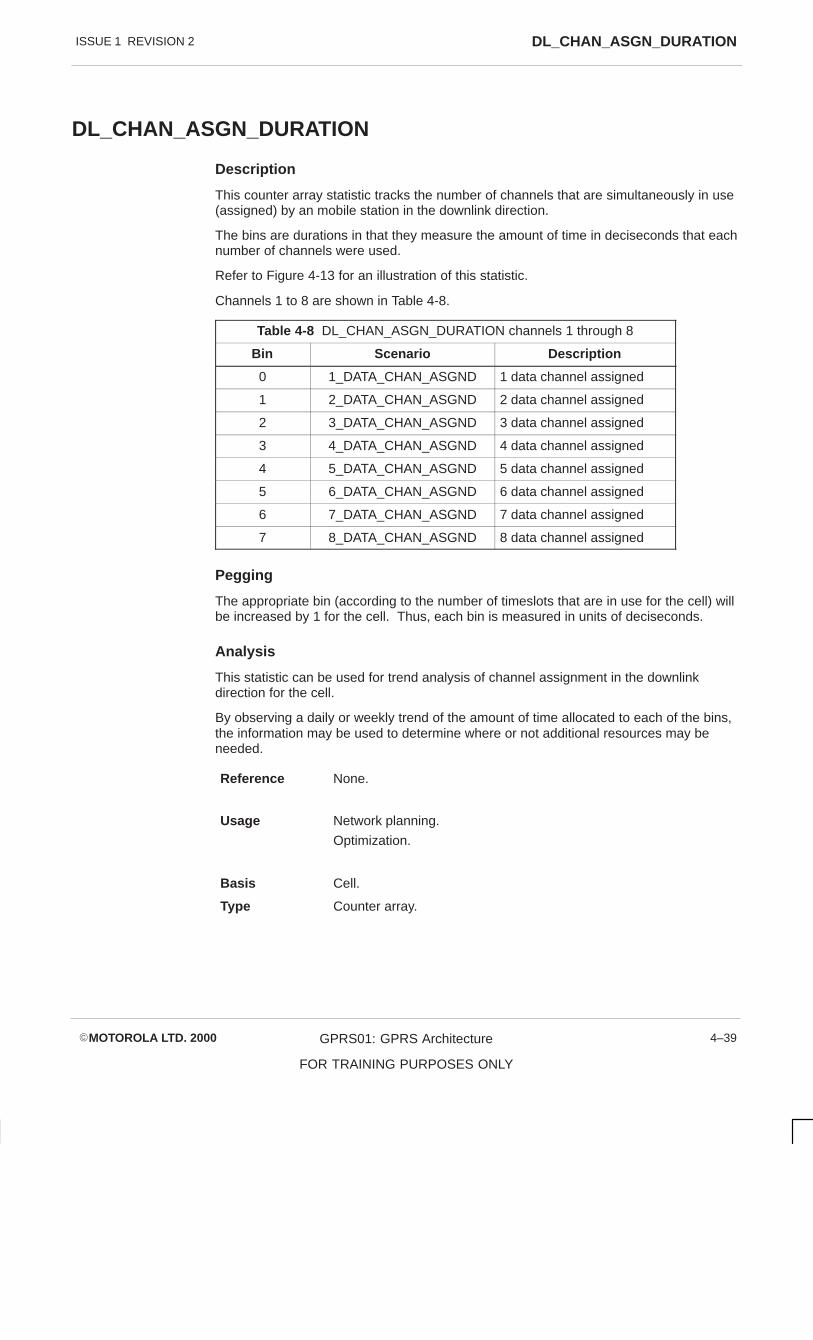
ISSUE 1 REVISION 2 DL_CHAN_ASGN_DURATION
�MOTOROLA LTD. 2000 GPRS01: GPRS Architecture
FOR TRAINING PURPOSES ONLY
4–39
DL_CHAN_ASGN_DURATION
Description
This counter array statistic tracks the number of channels that are simultaneously in use(assigned) by an mobile station in the downlink direction.
The bins are durations in that they measure the amount of time in deciseconds that eachnumber of channels were used.
Refer to Figure 4-13 for an illustration of this statistic.
Channels 1 to 8 are shown in Table 4-8.
Table 4-8 DL_CHAN_ASGN_DURATION channels 1 through 8
Bin Scenario Description
0 1_DATA_CHAN_ASGND 1 data channel assigned
1 2_DATA_CHAN_ASGND 2 data channel assigned
2 3_DATA_CHAN_ASGND 3 data channel assigned
3 4_DATA_CHAN_ASGND 4 data channel assigned
4 5_DATA_CHAN_ASGND 5 data channel assigned
5 6_DATA_CHAN_ASGND 6 data channel assigned
6 7_DATA_CHAN_ASGND 7 data channel assigned
7 8_DATA_CHAN_ASGND 8 data channel assigned
Pegging
The appropriate bin (according to the number of timeslots that are in use for the cell) willbe increased by 1 for the cell. Thus, each bin is measured in units of deciseconds.
Analysis
This statistic can be used for trend analysis of channel assignment in the downlinkdirection for the cell.
By observing a daily or weekly trend of the amount of time allocated to each of the bins,the information may be used to determine where or not additional resources may beneeded.
Reference None.
Usage Network planning.
Optimization.
Basis Cell.
Type Counter array.

ISSUE 1 REVISION 2TOTAL_AIR_DL_AVAILABLE_BW
�MOTOROLA LTD. 2000GPRS01: GPRS Architecture
FOR TRAINING PURPOSES ONLY
4–40
TOTAL_AIR_DL_AVAILABLE_BW
Description
This statistic counts the total number of Radio Link Control (RLC) data blocks availablefor downlink transfer at the PCU.
Pegging
The amount of available bandwidth is calculated by summing up the number of availableRLC blocks in a second (50, each takes up 20 milliseconds) and then multiplying by thenumber of timeslots both in use and not in use for GPRS.
Analysis
Reference None.
Usage Network planning.
Network accessiblility.
Basis Cell.
Type Counter.

ISSUE 1 REVISION 2 TOTAL_AIR_UL_AVAILABLE_BW
�MOTOROLA LTD. 2000 GPRS01: GPRS Architecture
FOR TRAINING PURPOSES ONLY
4–41
TOTAL_AIR_UL_AVAILABLE_BW
Description
This statistic counts the total number of RLC data blocks available for uplink transfer atthe PCU.
Pegging
The amount of available bandwidth is calculated by summing up the number of availableRLC blocks in a second (50, each one takes up 20 milliseconds), and then multiplying bythe number of timeslots both in use and not in use for GPRS.
Analysis
Reference None.
Usage Network planning.
Network accessiblity.
Basis Cell.
Type Counter.

ISSUE 1 REVISION 2UL_CHAN_ASGN_DURATION
�MOTOROLA LTD. 2000GPRS01: GPRS Architecture
FOR TRAINING PURPOSES ONLY
4–42
UL_CHAN_ASGN_DURATION
Description
This counter array statistic tracks the number of channels that are simultaneously in use(assigned) by a mobile station in the uplink direction.
The bins are durations in that they measure the amount of time in deciseconds that eachnumber of channels were used.
Refer to Figure 4-14 for an illustration of this statistic.
Channels 1 to 8 are shown in Table 4-9.
Table 4-9 DL_CHAN_ASGN_DURATION channels 1 through 8
Bin Scenario Description
0 1_DATA_CHAN_ASGND 1 data channel assigned
1 2_DATA_CHAN_ASGND 2 data channel assigned
2 3_DATA_CHAN_ASGND 3 data channel assigned
3 4_DATA_CHAN_ASGND 4 data channel assigned
4 5_DATA_CHAN_ASGND 5 data channel assigned
5 6_DATA_CHAN_ASGND 6 data channel assigned
6 7_DATA_CHAN_ASGND 7 data channel assigned
7 8_DATA_CHAN_ASGND 8 data channel assigned
Pegging
The appropriate bin (according to the number of timeslots are in use for the cell) will beincreased by 1 for the cell. Thus, each bin is measured in units of deciseconds.
Analysis
This statistic can be used for trend analysis of channel assignment in the uplink directionfor the cell.
By observing a daily or weekly trend of the amount of time allocated to each of the bins,the information may be used to determine where or not additional resources may beneeded.
Reference None.
Usage Network planning.
Optimization.
Basis Cell.
Type Counter array.

�MOTOROLA LTD. 2000 GPRS01: GPRS Architecture
FOR TRAINING PURPOSES ONLY
i
Chapter 5
GSN Architecture
ISSUE 1 REVISION 2
�MOTOROLA LTD. 2000GPRS01: GPRS Architecture
FOR TRAINING PURPOSES ONLY
ii

ISSUE 1 REVISION 2
�MOTOROLA LTD. 2000 GPRS01: GPRS Architecture
FOR TRAINING PURPOSES ONLY
iii
Chapter 5GSN Architecture i. . . . . . . . . . . . . . . . . . . . . . . . . . . . . . . . . . . . . . . . . . . . . . . . . . .
Objectives 5–1. . . . . . . . . . . . . . . . . . . . . . . . . . . . . . . . . . . . . . . . . . . . . . . . . . . . . . . . . . . . . . . . .
GPRS Overview 5–2. . . . . . . . . . . . . . . . . . . . . . . . . . . . . . . . . . . . . . . . . . . . . . . . . . . . . . . . . . . . GSN in GPRS 5–2. . . . . . . . . . . . . . . . . . . . . . . . . . . . . . . . . . . . . . . . . . . . . . . . . . . . . . . . GSN Software Architecture 5–4. . . . . . . . . . . . . . . . . . . . . . . . . . . . . . . . . . . . . . . . . . . . . SGSN Architecture 5–6. . . . . . . . . . . . . . . . . . . . . . . . . . . . . . . . . . . . . . . . . . . . . . . . . . . . Functional Entities and Hardware Mapping 5–8. . . . . . . . . . . . . . . . . . . . . . . . . . . . . . . CPX 8216 5–10. . . . . . . . . . . . . . . . . . . . . . . . . . . . . . . . . . . . . . . . . . . . . . . . . . . . . . . . . . . . System Configuration 5–12. . . . . . . . . . . . . . . . . . . . . . . . . . . . . . . . . . . . . . . . . . . . . . . . . . I/O Configurations 5–14. . . . . . . . . . . . . . . . . . . . . . . . . . . . . . . . . . . . . . . . . . . . . . . . . . . . . Power Supply 5–16. . . . . . . . . . . . . . . . . . . . . . . . . . . . . . . . . . . . . . . . . . . . . . . . . . . . . . . . . MCP 750 – L252 5–18. . . . . . . . . . . . . . . . . . . . . . . . . . . . . . . . . . . . . . . . . . . . . . . . . . . . . . MCP750 5–20. . . . . . . . . . . . . . . . . . . . . . . . . . . . . . . . . . . . . . . . . . . . . . . . . . . . . . . . . . . . . PMC 860 Module 5–22. . . . . . . . . . . . . . . . . . . . . . . . . . . . . . . . . . . . . . . . . . . . . . . . . . . . . ATTACH 5–24. . . . . . . . . . . . . . . . . . . . . . . . . . . . . . . . . . . . . . . . . . . . . . . . . . . . . . . . . . . . . ATTACH 5–26. . . . . . . . . . . . . . . . . . . . . . . . . . . . . . . . . . . . . . . . . . . . . . . . . . . . . . . . . . . . . ATTACH 5–28. . . . . . . . . . . . . . . . . . . . . . . . . . . . . . . . . . . . . . . . . . . . . . . . . . . . . . . . . . . . . ATTACH 5–30. . . . . . . . . . . . . . . . . . . . . . . . . . . . . . . . . . . . . . . . . . . . . . . . . . . . . . . . . . . . . Detach 5–32. . . . . . . . . . . . . . . . . . . . . . . . . . . . . . . . . . . . . . . . . . . . . . . . . . . . . . . . . . . . . . Explicit Detach 5–34. . . . . . . . . . . . . . . . . . . . . . . . . . . . . . . . . . . . . . . . . . . . . . . . . . . . . . . . Explicit Detach 5–36. . . . . . . . . . . . . . . . . . . . . . . . . . . . . . . . . . . . . . . . . . . . . . . . . . . . . . . . Implicit Detach 5–38. . . . . . . . . . . . . . . . . . . . . . . . . . . . . . . . . . . . . . . . . . . . . . . . . . . . . . . . Routing Area Update 5–40. . . . . . . . . . . . . . . . . . . . . . . . . . . . . . . . . . . . . . . . . . . . . . . . . . Blocking User Data Transfer 5–40. . . . . . . . . . . . . . . . . . . . . . . . . . . . . . . . . . . . . . . . . . . . Modify GMM Context 5–40. . . . . . . . . . . . . . . . . . . . . . . . . . . . . . . . . . . . . . . . . . . . . . . . . .
Session Management 5–42. . . . . . . . . . . . . . . . . . . . . . . . . . . . . . . . . . . . . . . . . . . . . . . . . . . . . . . PDP Context Activation MS Initiated 5–44. . . . . . . . . . . . . . . . . . . . . . . . . . . . . . . . . . . . . PDP Context Activation – Transmission function 5–46. . . . . . . . . . . . . . . . . . . . . . . . . . . Uplink Activation 5–48. . . . . . . . . . . . . . . . . . . . . . . . . . . . . . . . . . . . . . . . . . . . . . . . . . . . . . PDP Context Accept 5–48. . . . . . . . . . . . . . . . . . . . . . . . . . . . . . . . . . . . . . . . . . . . . . . . . . . Activate Downlink 5–50. . . . . . . . . . . . . . . . . . . . . . . . . . . . . . . . . . . . . . . . . . . . . . . . . . . . . PDP Context Deactivation 5–52. . . . . . . . . . . . . . . . . . . . . . . . . . . . . . . . . . . . . . . . . . . . . . Paging for GPRS Downlink Transfer 5–54. . . . . . . . . . . . . . . . . . . . . . . . . . . . . . . . . . . . . Paging 5–56. . . . . . . . . . . . . . . . . . . . . . . . . . . . . . . . . . . . . . . . . . . . . . . . . . . . . . . . . . . . . . . Transmission Function 5–58. . . . . . . . . . . . . . . . . . . . . . . . . . . . . . . . . . . . . . . . . . . . . . . . . SNDCP Peer to Peer 5–60. . . . . . . . . . . . . . . . . . . . . . . . . . . . . . . . . . . . . . . . . . . . . . . . . . SNDCP XID Parameters 5–60. . . . . . . . . . . . . . . . . . . . . . . . . . . . . . . . . . . . . . . . . . . . . . . LLC Peer to Peer 5–62. . . . . . . . . . . . . . . . . . . . . . . . . . . . . . . . . . . . . . . . . . . . . . . . . . . . . GGSN – PDP Context Activation 5–64. . . . . . . . . . . . . . . . . . . . . . . . . . . . . . . . . . . . . . . .

ISSUE 1 REVISION 2
�MOTOROLA LTD. 2000GPRS01: GPRS Architecture
FOR TRAINING PURPOSES ONLY
iv

ISSUE 1 REVISION 2 Objectives
�MOTOROLA LTD. 2000 GPRS01: GPRS Architecture
FOR TRAINING PURPOSES ONLY
5–1
ObjectivesOn completion of this course the students will be able to:
� Identify the major components of the GSN
� Understand the Generic function of GSN entities
� Identify the signalling between GSN entities for Mobility Management and SessionManagement
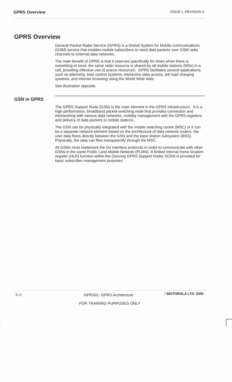
ISSUE 1 REVISION 2GPRS Overview
�MOTOROLA LTD. 2000GPRS01: GPRS Architecture
FOR TRAINING PURPOSES ONLY
5–2
GPRS OverviewGeneral Packet Radio Service (GPRS) is a Global System for Mobile communications(GSM) service that enables mobile subscribers to send data packets over GSM radiochannels to external data networks.
The main benefit of GPRS is that it reserves specifically for times when there issomething to send. the same radio resource is shared by all mobile stations (MSs) in acell, providing effective use of scarce resources. GPRS facilitates several applications,such as telemetry, train control systems, interactive data access, toll road chargingsystems, and internet browsing using the World Wide Web.
See illustration opposite.
GSN in GPRS
The GPRS Support Node (GSN) is the main element in the GPRS infrastructure. It is ahigh performance, broadband packet-switching node that provides connection andinterworking with various data networks, mobility management with the GPRS registers,and delivery of data packets to mobile stations.
The GSN can be physically integrated with the mobile switching centre (MSC) or it canbe a separate network element based on the architecture of data network routers. theuser data flows directly between the GSN and the base station subsystem (BSS).Physically, the data can flow transparently through the MSC.
All GSNs must implement the Gn interface protocols in order to communicate with otherGSNs in the same Public Land Mobile Network (PLMN). A limited internal home locationregister (HLR) function within the (Serving GPRS Support Node) SGSN is provided forbasic subscriber management purposes.

ISSUE 1 REVISION 2 GPRS Overview
�MOTOROLA LTD. 2000 GPRS01: GPRS Architecture
FOR TRAINING PURPOSES ONLY
5–3
Example of a GPRS system

ISSUE 1 REVISION 2GPRS Overview
�MOTOROLA LTD. 2000GPRS01: GPRS Architecture
FOR TRAINING PURPOSES ONLY
5–4
GSN SoftwareArchitecture
The GSN software architecture is designed on five functional planes. They are:
1. Control function
� Signalling information between different GPRS components, such as MS Attachand PDP activate.
� Macroscopic MS Context information
2. Transmission function
� Data traffic transmission between different GPRS components
� Microscopic MS Context Information
3. OAMP function
� Interface with OMC–G
� Interface with Control and Transmission function for collection of OAMP data (e.g.Statistics)
� Interface for forwarding of alarms to the OMC–G from the Control function andTransmission function
� Configuration Management of Control and Transmission function
4. Accounting Metering function
� Interface with external billing system
� Collection of billing information from Control and Transmission function
5. Network Support function
� Domain name server
� Time server

ISSUE 1 REVISION 2 GPRS Overview
�MOTOROLA LTD. 2000 GPRS01: GPRS Architecture
FOR TRAINING PURPOSES ONLY
5–5
System Framework
Billing/AccountingSystem
Network Support Server
OMC-G
Control Function
Transmission Function
Acc
ount
ing
Met
erin
g F
unct
ion
Acc
ount
ing
Met
erin
g F
unct
ion
OA
MP
Fun
ctio
n

ISSUE 1 REVISION 2GPRS Overview
�MOTOROLA LTD. 2000GPRS01: GPRS Architecture
FOR TRAINING PURPOSES ONLY
5–6
SGSNArchitecture
Functional Entities
The SGSN consists of the following software functional entities:
SGSN – CONTROL
Part of the Control Plane, the SGSN–CONTROL is responsible for handling SGSNsignalling, such as MS attach, PDP activate.
It contains macroscopic information about the MS, i.e. VLR
Transmission Function
The SGSN Transmission function is made up of two functional entities, theSGSN–GNPROC and the SGSN–GBPROC.
SGSN–GNPROC – Part of the transmission plane and responsible for GTP, Relay,SNDCP and LLC protocols. It serves as an anchor and point for an MS within an SGSN.Responsible for paging of MSs and receiving/forwarding data to/from the appropriateSGSN–GBPROC. The GNPROC contains microscopic MS context information; MS MMstate, PDP state and cell location.
SGSN–GBPROC – Also part of the transmission plane responsible for BSSGP protocol.Each GBPROC is connected to one BSS via a number of E1 links. The GBPROC isresponsible for QOS scheduling and flow control. The functional entity contains cell andframe relay PVC mapping.
SS7 Function
The SGSN has a number of interfaces to other network entities that use the SS7 protocolstack for signalling exchange. The SS7 function is the functional component identified tohandle these interfaces. For the trial system the SGSN SS7 function holds a internalHLR database to simulate a GR interface to a HLR.

ISSUE 1 REVISION 2 GPRS Overview
�MOTOROLA LTD. 2000 GPRS01: GPRS Architecture
FOR TRAINING PURPOSES ONLY
5–7
SGSN Architecture
SS7 FUNCTION
HLR
CONTROL FUNCTION
SGSN – CONTROL
SF
SGSN GNPROC
SGSN GbPROC
FR E1 FR E1
BSS
COMMHUB

ISSUE 1 REVISION 2GPRS Overview
�MOTOROLA LTD. 2000GPRS01: GPRS Architecture
FOR TRAINING PURPOSES ONLY
5–8
FunctionalEntities andHardwareMapping
The functional entities for the SGSN can be mapped to the same processor board ordistributed among processor boards. This allows the configuration of GSN to adapt tothe different needs of networks.
SGSN Architecture
The SGSN functional entities will be split into functions. The Control function and theTransmission function.
Control Function
The Control function will comprise an instance of SGSN–control and SGSN–OAMP. TheControl function holds the OAMP function for the CF and the TF.
Transmission Function
The SGSN–GBPROC and SGSN–GNPROC are combined together to form theTransmission function on a processor board. The board will have 2 mezzanine interfaceboards supporting up to 4 E1s to allow connection to the BSS.
SS7 Function
The SS7 function holds a internal HLR simulating a Gr interface to a HLR.

ISSUE 1 REVISION 2 GPRS Overview
�MOTOROLA LTD. 2000 GPRS01: GPRS Architecture
FOR TRAINING PURPOSES ONLY
5–9
Functional entities and hardware mapping
SF SGSN–CF SGSN TF
SF
HLR
OAMP
sgsn – control
tf
sgsn – gbproc
sgsn – gnproc
E1I/F
BSC

ISSUE 1 REVISION 2GPRS Overview
�MOTOROLA LTD. 2000GPRS01: GPRS Architecture
FOR TRAINING PURPOSES ONLY
5–10
CPX 8216
The CPX 8216 is a sixteen slot, high availability Compact PCI system with two separatesix slot Compact PCI 1/0 domains and the capability to contain redundant CPU modulesand redundant Hot–Swap Controller (HSC) modules in the remaining 2 slots of eachdomain.
CPX 8216 is designed as a highly reliable system by providing several levels of systemreliability based on hardware and software. The system allows for integration of standardoff–the–shelf Compact PCI hardware.

ISSUE 1 REVISION 2 GPRS Overview
�MOTOROLA LTD. 2000 GPRS01: GPRS Architecture
FOR TRAINING PURPOSES ONLY
5–11

ISSUE 1 REVISION 2GPRS Overview
�MOTOROLA LTD. 2000GPRS01: GPRS Architecture
FOR TRAINING PURPOSES ONLY
5–12
SystemConfiguration
The CPX 8216 is a flexible system that allows for multiple configuration of processorcontrol, its redundancy and peripheral configurations.
Three possible configurations:
� Simpler system containing a single CPU and Hop Swap Controller controlling bothdomains.
� An active/passive system where one pair of CPU and HSC control both domainswith a stby CPU and HSC.
� Active/Active – each CPU runs a single domain while also serving as a backup tothe other CPU.
For field trial the backplane is not used and there is no system slot processor.

ISSUE 1 REVISION 2 GPRS Overview
�MOTOROLA LTD. 2000 GPRS01: GPRS Architecture
FOR TRAINING PURPOSES ONLY
5–13
I/O
S
T
LO
I/O
S
T
LO
I/O
S
T
LO
I/O
S
T
LO
I/O
S
T
LO
I/O
S
T
LO
I/O
S
T
LO
I/O
S
T
LO
I/O
S
T
LO
I/O
S
T
LO
I/O
S
T
LO
I/O
S
T
LO
I/O
I/O
S
T
LO
I/O
S
T
LO
HSC
A
I/O
CPU
A
CPU
I/O DOMAIN BI/O DOMAIN A
I/O
S
T
LO
I/O
S
T
LO
I/O
S
T
LO
I/O
S
T
LO
I/O
S
T
LO
I/O
S
T
LO
I/O
S
T
LO
I/O
S
T
LO
I/O
S
T
LO
I/O
S
T
LO
I/O
S
T
LO
I/O
S
T
LO
I/O I/O
I/O
S
T
LO
I/O
S
T
LO
CPU
B
HSC
A
CPU
B
I/O I/O
CPU
A
HSC
B
CPU
I/O DOMAIN BI/O DOMAIN A
I/O
S
T
LO
I/O
S
T
LO
I/O
S
T
LO
I/O
S
T
LO
I/O
S
T
LO
I/O
S
T
LO
I/O
S
T
LO
I/O
S
T
LO
I/O
S
T
LO
I/O
S
T
LO
I/O
S
T
LO
I/O
S
T
LO
I/O I/O
I/O
S
T
LO
I/O
S
T
LO
CPU
B
HSC
A
CPU
B
I/O I/O
CPU
A
HSC
B
CPU
PASSIVECU/HSC
I/O DOMAIN BI/O DOMAIN A
ACTIVE CPU ACTIVE HSC
Simplex
Active /Passive
Active/Active

ISSUE 1 REVISION 2GPRS Overview
�MOTOROLA LTD. 2000GPRS01: GPRS Architecture
FOR TRAINING PURPOSES ONLY
5–14
I/OConfigurations
The CPX 8216 contains two independent eight slot Compact PCI buses. One slot ineach bus is dedicated to a system processor and the other is needed for the hop swapcontroller (HSC). This leaves six slots on each bus to support 1/0 devices ornon–system processors.

ISS
UE
1 RE
VIS
ION
2G
PR
S O
verview
�M
OTO
RO
LA LT
D. 2000
GP
RS
01: GP
RS
Architecture
FO
R T
RA
ININ
G P
UR
PO
SE
S O
NLY
5–15
12
34
56
78
910
1112
1314
1516
Rear S
lots
Front S
lots
I/O Slot (Black
I/O Slot (Black
I/O Slot (Black
I/O Slot (Black
I/O Slot (Black
I/O Slot (Black
CPU (Red)
None
CPU (Red)
None
CPU Tms (Red)
Bridge (Tan)
CPU Tms (Red)
Bridge (Tan)
I/O Tms (Black
I/O Slot (Black
I/O Slot (Black
I/O Slot (Black
I/O Slot (Black
I/O Slot (Black
I/O Slot (Black
I/O Tms (Black
I/O Tms (Black
I/O Tms (Black
I/O Tms (Black
I/O Tms (Black
I/O Tms (Black
I/O Tms (Black
I/O Tms (Black
I/O Tms (Black
I/O Tms (Black
I/O Tms (Black
Backplane

ISSUE 1 REVISION 2GPRS Overview
�MOTOROLA LTD. 2000GPRS01: GPRS Architecture
FOR TRAINING PURPOSES ONLY
5–16
Power Supply
The CPX 8216 requires a minimum of two power/fan slot modules and a fan only slotmodule to provide adequate cooling. The system can contain a third power supply/fanslot as part of an N+1 strategy. The modules are hot swapable for AC and DCenvironments.
The fans on the power supplies provide the forced air cooling for the cage. Only two fansare necessary for adequate system cooling with the third fan providing N+1 coolingredundancy.
The power distribution panel is located in the rear of the chassis below the transitionmodule card cage, distributes Ac or DC input power to the system power supplies.These three versions of power distribution power supply; AC, single input DC and dualinput DC.
Power Supply O/P
VOLTAGE REGULATION MINIMUM LOAD MAXIMUM LOAD
+5.06V �3% 0.5A 40.0A
+3.36V �3% 0.5A 40.0A
–12.1V �5% 0.3A 8.0A
+12.1V �5% 0.3A 4.0A
Power Supply I/P
VOLTAGE FREQUENCY INPUT CURRENT
AC 90 – 132
or 190 – 260Vac
47 – 63Hz 6.0A max at 115Vac
3A max at 220Vac
DC 40 – 72Vdc – 113A – 48Vdc at 475V

ISSUE 1 REVISION 2 GPRS Overview
�MOTOROLA LTD. 2000 GPRS01: GPRS Architecture
FOR TRAINING PURPOSES ONLY
5–17

ISSUE 1 REVISION 2GPRS Overview
�MOTOROLA LTD. 2000GPRS01: GPRS Architecture
FOR TRAINING PURPOSES ONLY
5–18
MCP 750 – L252
MCP 750 is a single slot single board computer equipped with an MCP 750 power PCTM 750 series microprocessor. The card has the following characteristics:
� 128 MB DRAM
� One MB flash memory on board (16 bit)
� Additional 64 bit 8 MB flash memory
� Compact flash memory with 48MB compact flash
� One 10/100 Base TX Ethernet port
� One Async Serial port
� One PMC slot
� USB

ISSUE 1 REVISION 2 GPRS Overview
�MOTOROLA LTD. 2000 GPRS01: GPRS Architecture
FOR TRAINING PURPOSES ONLY
5–19

ISSUE 1 REVISION 2GPRS Overview
�MOTOROLA LTD. 2000GPRS01: GPRS Architecture
FOR TRAINING PURPOSES ONLY
5–20
MCP750
MCP 750 offers many features desirable in a Compact PCI computer system, such as:
Compact PCI Bus – MCP750 interfaces to a Compact Peripheral Component Bus (CPCI)using a PCI to PCI bridge. This device allows 64 bit primary and secondary data accessto the CPCI bus on the cage backplane and the on–board local CPCI bus.
The I/0 peripheral interfaces present on the onboard PCI bus include:
� 10/100 Base T Ethernet interface
� UDB host controller
� Fast EIDE interface
� One PMC slot
From the ISA bus are:
� 2 async serial ports
� 2 async/synch serial ports
� keyboard port
� mouse port
� floppy disk controller
� parallel port
� real time clock
� NVRAM
Key to the MCP750 is the industry standard mezzanine interface (DCI Mezzanine Card).PCI modules offer a variety of possibility for 1/0 expansion.

ISSUE 1 REVISION 2 GPRS Overview
�MOTOROLA LTD. 2000 GPRS01: GPRS Architecture
FOR TRAINING PURPOSES ONLY
5–21
MCP 750 Block Diagram

ISSUE 1 REVISION 2GPRS Overview
�MOTOROLA LTD. 2000GPRS01: GPRS Architecture
FOR TRAINING PURPOSES ONLY
5–22
PMC 860 Module
The PMC/860 module has been designed to provide network interface functionality for E1or T1 lines on a single slot PMC format via the front panel or via rear transition module1/0.
PMC/860 provides:
� PCI bus interface via PMC connectors
� 2 E1 or T1 line interfaces via front panel
� Serial 1/0 port
� 40mhz Power DUICC processor
� 4MB DRAM
� 128 KB span
� Up to 2MB boot flash PROM
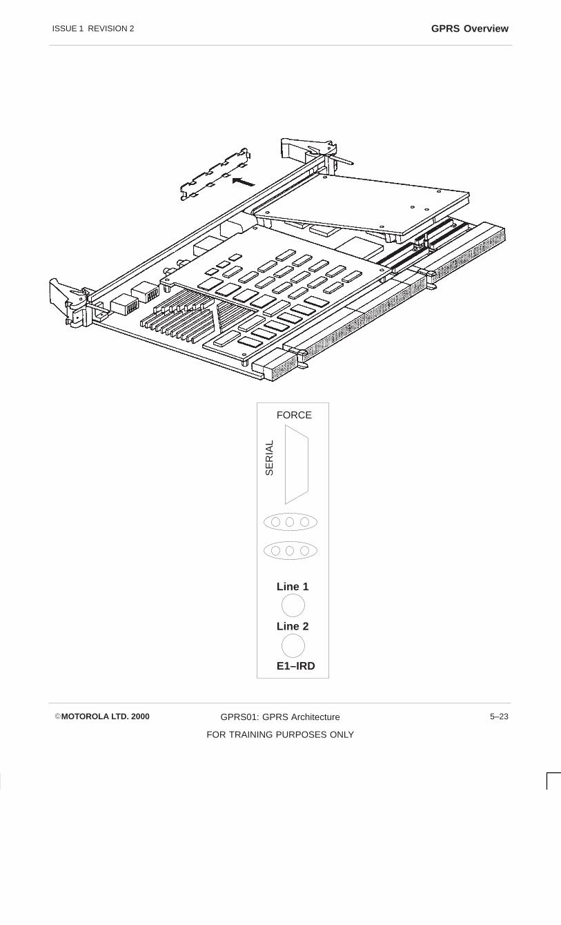
ISSUE 1 REVISION 2 GPRS Overview
�MOTOROLA LTD. 2000 GPRS01: GPRS Architecture
FOR TRAINING PURPOSES ONLY
5–23
FORCE
SE
RIA
L
Line 1
Line 2
E1–IRD

ISSUE 1 REVISION 2GPRS Overview
�MOTOROLA LTD. 2000GPRS01: GPRS Architecture
FOR TRAINING PURPOSES ONLY
5–24
ATTACH
The MS makes an Attach procedure by the sending of an Attach Request to the SGSN.The Request contains the information elements:–
� Attach Type – GPRS or IMSI or Combined Attach
� MS Network Capability – SMS + Encryption Algorithm capab
� Ciphering Key Sequence
� QOS Parameters
� Force to Stby
� Old P–TMSI or IMSI
� MS Radio Access Capabilities – includes power capability multiple class
� Old RAI
� Requested ready timer value
If the mobile identifies itself using a PTMSI for which the SGSN CF has no GPRSMobility Management (GMM) context, then Subscriber Identification takes place to gainthe MS IMSI. If the IMSI is included in the Attach Request then examination of the IMSIto determine if the MS belongs to the SGSN PLMN is carried out.
Subscriber Identification is performed by the SGSN CF sending an Identity Request tothe MS requesting the MS IMSI. The MS will respond with an IDENTITY RESPONSEcontaining the IMSI.

ISSUE 1 REVISION 2 GPRS Overview
�MOTOROLA LTD. 2000 GPRS01: GPRS Architecture
FOR TRAINING PURPOSES ONLY
5–25
MS CF
ATTACH REQUEST
IDENTITY REQUEST
IDENTITY RESPONSE

ISSUE 1 REVISION 2GPRS Overview
�MOTOROLA LTD. 2000GPRS01: GPRS Architecture
FOR TRAINING PURPOSES ONLY
5–26
ATTACH
HLR Interaction
As the SGSN CF does not have a GMM context for the MS, the HLR must be updatedwith the location of the MS by sending an HPDATE LOCATION LOCATION messageidentifying the SGSN and including the MS IMSI.
Updating the HLR with the new MS location results in the HLR sending the SGSN thesubscriber data.
FIELD DESCRIPTION
IMSI IMSI is the main reference key.
MSISDN The basic MSISDN of the MS.
SGSN Number The SS7 address of the SGSN currently serving thisMS.
SGSN Address The IP address of the SGSN currently serving thisMS.
SMS Parameters SMS–related parameters, e.g. operator–determinedbarring.
MS Purged for GPRS Indicates that the MM and PDP contexts of the MSare deleted from the SGSN.
MNRG Indicates that the MS is not reachable through anSGSN, and that the MS is marked as not reachablefor GPRS at the SGSN and possibly at the GGSN.
GGSN–list The GSN number and optional IP address pairrelated to the GGSN that shall be contacted whenactivity from the MS is detected and MNRG is set.The GSN number shall be either the number of theGGSN or the protocol–converting GSN as describedin the subclauses “MAP–based GGSN – HLRSignalling” and “GTP and MAP–based GGSN – HLRSignalling”.
Each IMSI contains zero or more of the following PDP context subscription records:
PDP Type PDP type, e.g. X.25 or IP.
PDP Address PDP address, e.g. an X.121 address. This field shallbe empty if dynamic addressign is allowed.
QoS Profile Subscribed The quality of service profile subscribed for this PDPcontext. QoS Profile Subscribed is the default level ifa particular QoS profile is not requested.
VPLMN Address Allowed Specifies whether the MS is allowed to use the APNin the domain of the HPLMN only, or additionally theAPN in the domain of the VPLMN.
Access Point Name A label according to DNS naming conventionsdescribing the access point to the external packetdata network.
The SGSN CF creates an MM Context for MS and stores the MS GMM Contextinformation (IMSI, MS NETWORK CAPABILITIES, DRX PARAMETERS, CELL ID andRAI) and the MS PDP CONTEXT information (IMSI, PDP Address, QoS Subscribed,Dynamic Address Allowed, VPLMN address allowed and Access Point Name.

ISSUE 1 REVISION 2 GPRS Overview
�MOTOROLA LTD. 2000 GPRS01: GPRS Architecture
FOR TRAINING PURPOSES ONLY
5–27
MS CF
ATTACH REQUEST
IDENTITY REQUEST
IDENTITY RESPONSE
HLR
UPDATE LOCATION
INSERT SUBSCRIBER DATA
INSERT SUBSCRIBER DATA ACK
UPDATE LOCATION

ISSUE 1 REVISION 2GPRS Overview
�MOTOROLA LTD. 2000GPRS01: GPRS Architecture
FOR TRAINING PURPOSES ONLY
5–28
ATTACH
If the Attach Request message is valid, and the SGSN CF has identified the MS and itbelongs to the SGSN PLM, then the SGSN CF will attempt to configure the TransmissionFunction (TF). The configuration will allocate a new Local TLLI and create a TF GMMcontext.
TLLI Assignment Procedure
Temporary Logical Link Identity (TLLI) consists of 32 bits built either on the basis of aP–TMSI in the case of local or foreign TLLI or a random number in the case of RandomTLLI. MS derives TLLI from the P–TMSI allocated to it from the SGSN.
TLLI BITS
31 30 29 28 27 26–0 TYPE OF TLLI
1 1 T T T T Local
1 0 T T T T Foreign
0 1 1 1 1 R Random
T = Bits derived from P–TMSI
R = Random Bits
A local TLLI is the same as a P–TMSI with the high order bits 31 and 30 set to one andthe rest of the bits set to the P–TMSI. The CF and Tf share the responsibility for theformation of the TLLI, the CL being responsible for the top 16 bits and the TF beingresponsible for the bottom 16 bits.
The CF encodes the portion of the local TLLI and passes it to the TF in the CreateMMCtx_REQ message along with GMM context information for the MS for the TF tostore in its Mobility Management (MM) context.
The TF creates an MM entity for the MS, storing the MM timer values, IMSI, RadioAccess Capabilities and DRX Parameters. The TF concedes its half of the TLLI andreturns the completed local TLLI to the SGSN CF in the CREATEMMCtx_CNF message.The CF now has the complete local TLLI and therefore the P–TMSI as Local TLLI =P–TMSI.

ISSUE 1 REVISION 2 GPRS Overview
�MOTOROLA LTD. 2000 GPRS01: GPRS Architecture
FOR TRAINING PURPOSES ONLY
5–29
MS CF
ATTACH REQUEST
IDENTITY REQUEST
IDENTITY RESPONSE
HLR
UPDATE LOCATION
INSERT SUBSCRIBER DATA
INSERT SUBSCRIBER DATA ACK
UPDATE LOCATION ACK
TF
CREATE MMCTx – REQ
INSERT SUBSCRIBER DATA
CREATE MMCTx – CNF
ATTACH ACCEPT
ATTACH COMPLETE

ISSUE 1 REVISION 2GPRS Overview
�MOTOROLA LTD. 2000GPRS01: GPRS Architecture
FOR TRAINING PURPOSES ONLY
5–30
ATTACH
The SGSN CF, upon return of the complete Local TLLI/P–TMSI from the TF, will send theATTACH ACCEPT message to the MS containing:–
� Attach Result – GPRS only or combined GPRS/IMSI attached Force to Stby
� Periodic RA Timer
� Radio Priority for SMS – Radio Priority Level 1–4
� Routing Area Identification
� Alloc PTMSI – P–TMSI = Local TLLI
� Ready Timer Value – SGSN Configured Value
The GPRS Mobility Management (GMM) context at the SGSN CF will go toGMM–REGISTERED PENDING until the MS replies with the ATTACH CompleteMessage. On receipt of the complete message from the MS using the assigned LocalTLLI the GMM state goes to GMM–REGISTERED.
GPRS Attach Failure Response
Identity Request Timer T3322 STARTED IDENTITY REQ
RANGE 8 SECS STOPPED IDENTITY RESP
RE–SEND MAXIMUM MAX_ACCEPT_ATTEMPT
Attach Accept T3350 STARTED ACCEPT ACCEPT
STOPPED ATTACH COMPLETE
RE–SEND MAXIMUM MAX_IDENTIFICATION_ATTEMPT
If the Attach fails due to either HLR having no need of IMSI or Failure of Transmissionfunction or Communication failure, the CF will send an Attach Reject to the MS andperform an Implicit Detach and log the event.
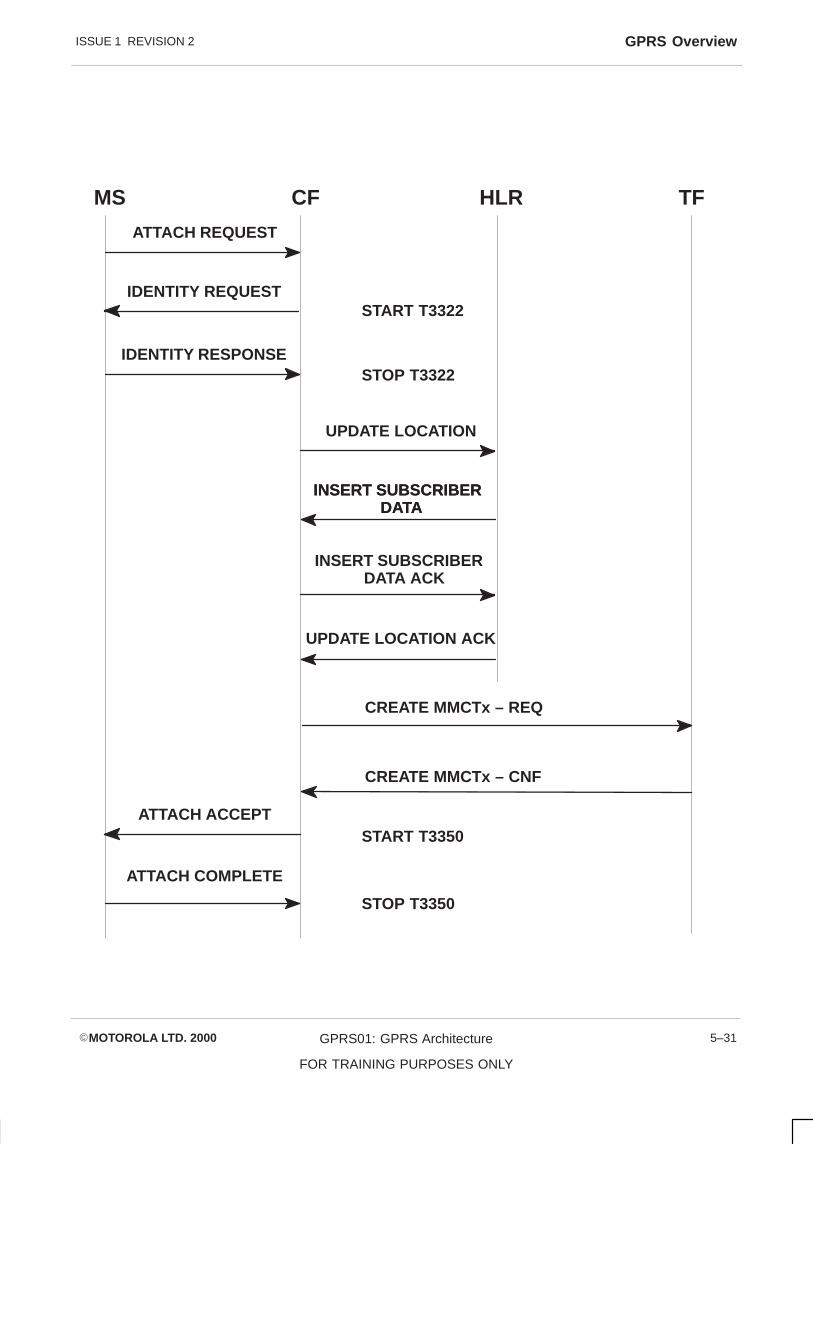
ISSUE 1 REVISION 2 GPRS Overview
�MOTOROLA LTD. 2000 GPRS01: GPRS Architecture
FOR TRAINING PURPOSES ONLY
5–31
MS CF
ATTACH REQUEST
IDENTITY REQUEST
IDENTITY RESPONSE
HLR
UPDATE LOCATION
INSERT SUBSCRIBER DATA
INSERT SUBSCRIBER DATA ACK
UPDATE LOCATION ACK
TF
CREATE MMCTx – REQ
INSERT SUBSCRIBER DATA
CREATE MMCTx – CNF
ATTACH ACCEPT
ATTACH COMPLETE
START T3350
STOP T3350
START T3322
STOP T3322

ISSUE 1 REVISION 2GPRS Overview
�MOTOROLA LTD. 2000GPRS01: GPRS Architecture
FOR TRAINING PURPOSES ONLY
5–32
Detach
The Detach function enables a mobile to become detached from the network or for thenetwork to detach a mobile from the network. There are two types of detach; Implicitand Explicit detach.
Explicit Detach: MS or Network explicitly requests detach.
Implicit Detach: Occurs in either or both MS and SGSN. No messages exchanged between MS and SGSN.
Reason: Mobile Reachable Timer ExpirationLower Layer Failure occursPaging Fault occursTransmission Configuration occurs
Switch Off
If the Detach is implicit then messaging is passed between the MS and SGSN which willindicate if the detach is due to switch off or not. The result of a detach request with adetach type indicating switch off = TRUE means a Detach Accept message would not bereturned by the network.

ISSUE 1 REVISION 2 GPRS Overview
�MOTOROLA LTD. 2000 GPRS01: GPRS Architecture
FOR TRAINING PURPOSES ONLY
5–33
MS SGSN
DETACH REQUEST
DETACH RESPONSE
DETACH REQUEST
or
DETACH RESPONSE
MS SGSN
DETACH REQUEST
SWITCH OFF = TRUE

ISSUE 1 REVISION 2GPRS Overview
�MOTOROLA LTD. 2000GPRS01: GPRS Architecture
FOR TRAINING PURPOSES ONLY
5–34
Explicit Detach
Explicit Detach is an MS or SGSN detach explicitly requested by one of the elements.Reasons for an Explicit detach could be due to:
1. Insert Subscriber Data from the HLR
2. Unexpected signalling or PTP PDU transfer faults
3. GTP error indication from GGSN
The Control Function (CF) on initiation of an Explicit Detach will attempt to:
1. Message the MS to Detach
2. Delete all active associated PDP contexts in the GGSN if possible
3. Deactivate active associated PDP contexts in the SSGN TF
4. Deactivate associated GMM context in the TF and move to GMM_Deregisteredstate for MS
On initiation of an Explicit Detach from the MS the SGSN CF uses the detach type todetermine the actions required for the detach.
The SGSN CF retrieves the GMM context and PDP context information from its ownGMM context and PDP context and the TF GMM context + PDP context using theGetMMCtx_PE2 message.

ISSUE 1 REVISION 2 GPRS Overview
�MOTOROLA LTD. 2000 GPRS01: GPRS Architecture
FOR TRAINING PURPOSES ONLY
5–35
MS CF
DETACH REQUEST SGSN
GET MMCTx – REQ
SGSN
TFTLLI, IMSI, DETACH TYPE,
FORCE TO STBY
(TLLI, IMSI)
GET MMCTx – CNF
TLLI, IMSI, MM CTX INFO

ISSUE 1 REVISION 2GPRS Overview
�MOTOROLA LTD. 2000GPRS01: GPRS Architecture
FOR TRAINING PURPOSES ONLY
5–36
Explicit Detach
Once the GMM context and active associated PDP contexts have been recovered by theSGSN CF, the PDP contexts are deactivated by sending a Delete PDP Context Requestmessage to GGSN, identifying the PDP contexts by their TID (IMSI and NSAPI). Todelete the PDP contexts at the SGSN TF the message Delete Contx_Req is sentidentifying each PDP context by their IMSI, NSAPI, TLLI. On return of responsemessages from the GGSN and TF that the PDP contexts have been deleted the CF canput its PDP contexts for the MS to INACTIVE.
The SGSN CF can now send the Detach Accept message (identified by TLLI) to the MS.To allow this message the GMM context for MS is maintained at the TF to allow thismessage to be sent. The time T_CF_TXCTL_DELAY01 controls a delay after sending ofDetach Accept before the SGSN CF can send Delete MMCntx_Req to the TF to removethe GMM context for the MS and put the MM context at the SGSN CF to idle.
Network Initiated Explicit Detach
A network initiated detach follows the same procedure as an MS initiated detach. Thedifference is that the Detach Request contains a GMM cause value to indicate why thedetach was initiated. The network will proceed to delete all PDP contexts for the MS andwill wait until the reception of Detach Accept before deleting the GMM Context for the TFand putting the SGSN CF GMM Context to idle for the MS.

ISSUE 1 REVISION 2 GPRS Overview
�MOTOROLA LTD. 2000 GPRS01: GPRS Architecture
FOR TRAINING PURPOSES ONLY
5–37
MS CF
DETACH REQUEST
SGSN
GET MMCtx – REQ
TFSGSN
TLLI, IMSI, detach type, force to stby
(TLLI, IMSI)
GET MMCtx – CNF (TLLI, IMSI, MMCTx info)
GGSN
Delete PDP Context Request(TID)
Delete PDP Context Response(TID)
SGSNTF
Delete PDP Cntx – Req (TLLI, NSAPI, IMSI)
Delete PDP Cntx – Cnf (TLLI, NSAPI, IMSI RESULT CODE)
DETACH ACCEPT
(TLLI)START T_CF_TxCTL_DELAY01
EXPIRY T_CF_TxCTL_DELAY01
DELETE MMCTX – Req (TLLI, IMSI)
DELETE MMCTX – Cnf (TLLI, IMSI, RESULT CODE)

ISSUE 1 REVISION 2GPRS Overview
�MOTOROLA LTD. 2000GPRS01: GPRS Architecture
FOR TRAINING PURPOSES ONLY
5–38
Implicit Detach
Implicit Detach occurs when a Lower Layer Failure occurs or GMM Mobile ReachableTimer expires. This occurs in both the MS and SGSN and each separately follow aprocedure to become GPRS detached. It is called Implicit Detach as there is nomessaging between the MS and the SGSN.
The procedure for an Implicit Detach is on the arrival of a Status_Ind message from theTransmission Function (TF) indicating Mobile Reachable Timer expiry or Lower LayerFailure or a Page Ind where the SGSN cannot find a GMM context associated with theIMSI.
The SGSN CF then follows the detach procedure without sending a Detach Requiredmessage to the MS. Removing GMM and PDP contexts from the TF and GGSN andchanging the PDP context to inactive and the GMM Context is idle for the MS.

ISSUE 1 REVISION 2 GPRS Overview
�MOTOROLA LTD. 2000 GPRS01: GPRS Architecture
FOR TRAINING PURPOSES ONLY
5–39
MS CFSGSN
GET MMCtx – REQ
TFSGSN
TLLI, IMSI
GET MMCtx – CNF
GGSN
Delete PDP Context Request(TID)
Delete PDP Context Response(TID)
SGSNTF
Delete PDP Ctx – Req (TLLI, NSAPI, IMSI)
Delete PDP Ctx – Cnf (TLLI, NSAPI, IMSI RESULT CODE)
DELETE MMCTX – Req (TLLI, IMSI)
DELETE MMCTX – Cnf (TLLI, IMSI, RESULT CODE)
TLLI, IMSI, MMCtx info

ISSUE 1 REVISION 2GPRS Overview
�MOTOROLA LTD. 2000GPRS01: GPRS Architecture
FOR TRAINING PURPOSES ONLY
5–40
Routing AreaUpdate
A Routing area update occurs when a GPRS attached MS enters a new Routing Area(RA) or when the Periodic Routing Area timer has expired. There are two types ofRouting area updates; Intra SGSN – where the MS has moved into a Routing Areacontrolled by the same SGSN, or Inter SGSN – where the MS has entered a newRouting Area controlled by a new SGSN.
Intra SGSN
On receipt of a Routing Area Update, the SGSN CF must determine if there is a GMMcontext for the MS. If the MS used a Local TLLI then there must be a GMM context forthe MS for the Routing Area Update to be an Intra SGSN.
If the MS uses a foreign TLLI, the TF can not determine the IMSI for the MS. The CFcan convert the foreign TLLI to a Local TLLI and query the TF for the IMSI and MMContext information to check the Ready, Mobile Reachable, MS Radio Access Capability.
Blocking UserData Transfer
As the MS has entered into a new cell location, downlink user data transfer is suspendedfor the MS until the TF is updated with the new cell location. SGSN CF commands theTL using BLOCKTX_Req to stop dl data transfer.
Modify GMMContext
The CF now processes the Routing Area Update, the new Routing Area ld is desiredfrom the BSSGP layer which contains the Cell Global ID. If GMM context informationrequires change, such as Ready Timer values, the CF will modify the TF GMM contextand then send the Routing Area Accept.
The SGSN CF, upon completion of the Routing Area Update function, will unblock thedownlink data transfer at the SGSN TF.

ISSUE 1 REVISION 2 GPRS Overview
�MOTOROLA LTD. 2000 GPRS01: GPRS Architecture
FOR TRAINING PURPOSES ONLY
5–41
MS CF
ROUTING AREA UPDATE REQUEST
SGSN
GET MMCTx – REQ
SGSNTF
fTLLI, UPDATE TYPE, OLD RAI, MS RADIO ACCESSCAPABILITIES, REQ READYTIMER VALUES
(TLLI)
GET MMCTx – CNF
TLLI, IMSI, MMCTx INFO
BLOCKTx–REQ
(TLLI)
BLOCKTx–REQ
(TLLI)
MODIFY MMCtx–REQ
TLLI, IMSI, NEW CGI,TIMER VALUES, MSRADIO ACCESS CAPAB,DRX PARAMETERS
MODIFY MMCtx–CNF
TLLI, IMSI, RESULTROUTING AREA ACCEPT
TLLI, IMSI, Force to Stby,update result, RDY timer
Unblock Tx–REQ(TLLI)
Unblock Tx–CNF(TLLI)

ISSUE 1 REVISION 2Session Management
�MOTOROLA LTD. 2000GPRS01: GPRS Architecture
FOR TRAINING PURPOSES ONLY
5–42
Session ManagementSession Management is concerned with the management of virtual connections (PDPcontexts) between an MS and an SGSN and a GGSN. Each active PDP context definesa virtual path between the MS and a Destination PTP address.
Point to Point subscriptions contain subscriptions to one or more PDP addresses. EachPDP address is described by a PDP context in the MS, SGSN and the GGSN.
The Session Activation function activates a PDP context for a subscriber. The PDPcontext established will be for a specified quality of service (QoS) on a specified NSAPI.
The PDP state model for a PDP context has two states;
Active – the context holds the routing information necessary to process PDUs for a PDPaddress between an MS and GGSN. During Active state the PDP context is updatedaccording to changed subscriber location. Active state is permitted only when theMobility Management state is Standby or Ready.
Inactive – The PDP context does not contain the routing information necessary toprocess a PDU for a particular address . PDP contexts are moved to inactive stateduring deactivation procedure. The active PDP contexts for an MS are moved toINACTIVE when the MM state changes to IDLE.

ISSUE 1 REVISION 2 Session Management
�MOTOROLA LTD. 2000 GPRS01: GPRS Architecture
FOR TRAINING PURPOSES ONLY
5–43
PDP State Model
INACTIVE
ACTIVE
ACTIVATE PDPCONTEXT
DEACTIVATEPDP CONTEXT
orMM STATE
changes to idle

ISSUE 1 REVISION 2Session Management
�MOTOROLA LTD. 2000GPRS01: GPRS Architecture
FOR TRAINING PURPOSES ONLY
5–44
PDP ContextActivation MSInitiated
The MS initiates PDP context activation with an Activate PDP context request message.The message contains PDP context parameters required to set up a PDP contextbetween an MS and an SGSN and a GGSN. Information elements include:
– NSAPI
– PDP type
– PDP Address (leaves blank to request dynamic address)
– Access Point Name (reference point to external network, via DNS)
The SGSN CF on receipt of a session activation request retrieves the MobilityManagement context and the PDP context associated with the subscriber. Thisinformation was stored during the GPRS attach procedure.
The Control Function now validates the PDP context request to ensure that therequested QOS can be met. If the message is valid then the function continues. The CFfirst configures the Transmission function before the GGSN for the PDP context, thusallowing the buffering of PDUs from the GGSN to be buffered.

ISSUE 1 REVISION 2 Session Management
�MOTOROLA LTD. 2000 GPRS01: GPRS Architecture
FOR TRAINING PURPOSES ONLY
5–45
MS CFSGSN
ACTIVATE PDP CONTEXTREQUEST
CONTEXT FOR MS

ISSUE 1 REVISION 2Session Management
�MOTOROLA LTD. 2000GPRS01: GPRS Architecture
FOR TRAINING PURPOSES ONLY
5–46
PDP ContextActivation –Transmissionfunction
The Control Function (CF) sends a PDP context activation message detailing the TLLI,IMSI, NSAPI, QOS and GGSN IP address. This information allows the Transmissionfunction to set up and identify the virtual paths to route PDUs to and from the MS andGGSN. The Transmission Function (TF) will inform the SGSN of the result ofconfiguration for the PDP context.
GGSN Configuration
Once the TF has been configured for the PDP context, enabling the buffering of PDUs tothe MS from the GGSN, then the Control function attempts to activate the PDP context inthe GGSN. The GGSN that the SGSN CF selects can be determined from threesources:
� Access Point Name from Subscriber data from HLR
� Access Point Name from MS in PDP Context Request, used if APN is notspecified in Subscriber data.
� Default GGSN address configured in SGSN CF.
The Create PDP Context Request message is sent to the GGSN with the PDP contextinformation elements required to create a PDP context at the GGSN for the MS,including; SGSN address, TID, PDU negotiated, End User address and protocolconfiguration options.
The GGSN creates a new entry in its PDP context table, storing the informationnecessary to route PDUs from the SGSN to an external network entity.
The GGSN returns a PDP Context Response message indicating whether TCP or UDPwill be used to transport PDU between the SGSN and GGSN. Also included are the TID,GGSN address, Cause Value indicating the success of the function.

ISSUE 1 REVISION 2 Session Management
�MOTOROLA LTD. 2000 GPRS01: GPRS Architecture
FOR TRAINING PURPOSES ONLY
5–47
MS CFSGSN
TFSGSN
GGSN
Create PDP Context Request
Create PDP Context Response
Activate PDPContext Request
CONTEXT FOR MS
Create PDPCtx_REQ
Create PDPCtx_CNF

ISSUE 1 REVISION 2Session Management
�MOTOROLA LTD. 2000GPRS01: GPRS Architecture
FOR TRAINING PURPOSES ONLY
5–48
Uplink Activation
Once the SGSN Control Function (CF) has received a successful PDP ContextResponse from the GGSN, the function will activate the Uplink MS to External NetworkEntity. This ensures that the Transmission Function (TF) can process uplink PDUs fromthe MS when the Activate PDP Context Accept is sent to the MS. The Control Functionsends an Activate Uplink Req message to TF referring to the context by TLLI, IMSI andNSAPI and including the path protocol to be used for transport of PDUs, UDP or TCP.The TF will respond with Activate Uplink_CNF with result of function.
PDP ContextAccept
After receipt from the Transmission function of successful activation of the uplink, thecontrol function sends an Activate PDP Context Accept message to the MS. Themessage returns the PDP parameters for a PDP context. Included in the message are:
Transaction Identifier – from MS PDP Context Request Message
Negotiated QOS – Returned QOS profile
Negotiated LLC SAPI – Returned LLC SAPI
Radio Priority – Value for QOS
PDP Address – PDP address for MS
After sending the PDP Context Accept message the SGSN CF sets the CF PDP Contextfields with the PDP context information, NSAPI, Negotiated QOS, State, GGSN addressin use, PDP address, QOS Requested.
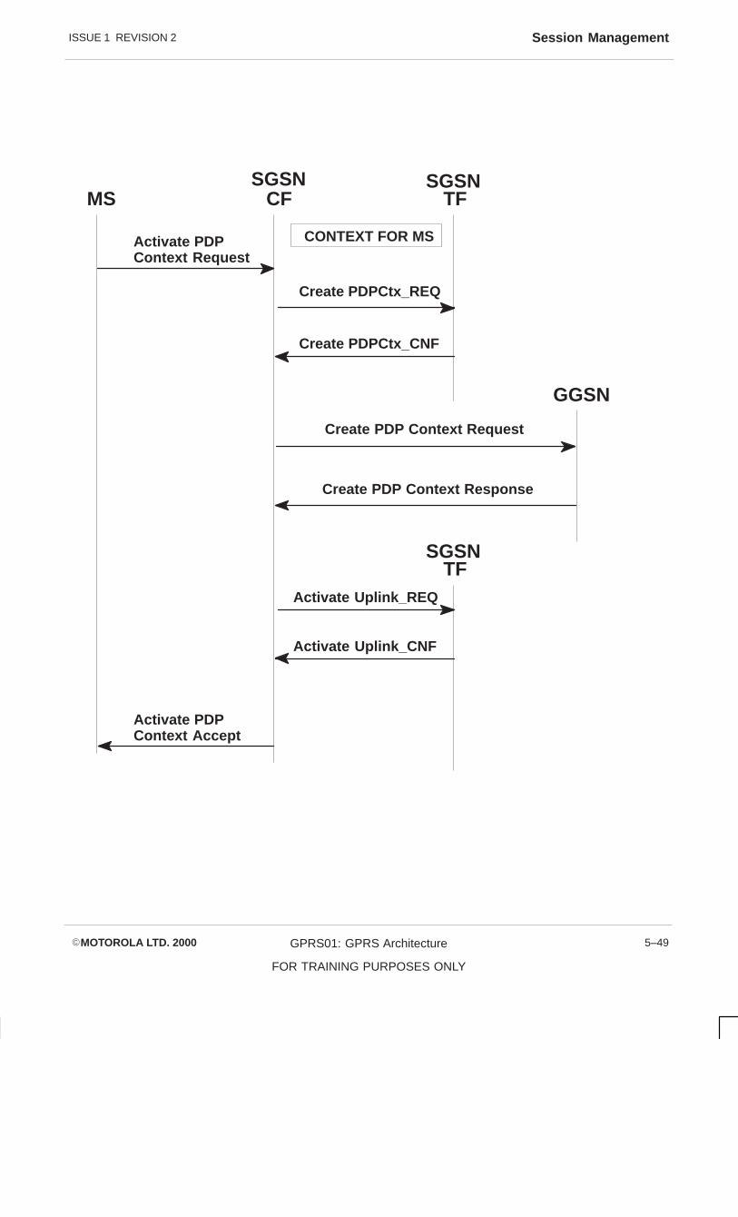
ISSUE 1 REVISION 2 Session Management
�MOTOROLA LTD. 2000 GPRS01: GPRS Architecture
FOR TRAINING PURPOSES ONLY
5–49
MS CFSGSN
TFSGSN
GGSN
Create PDP Context Request
Create PDP Context Response
Activate PDPContext Request
CONTEXT FOR MS
Create PDPCtx_REQ
Create PDPCtx_CNF
SGSNTF
Activate Uplink_REQ
Activate Uplink_CNF
Activate PDPContext Accept
ISSUE 1 REVISION 2Session Management
�MOTOROLA LTD. 2000GPRS01: GPRS Architecture
FOR TRAINING PURPOSES ONLY
5–50
ActivateDownlink
After sending an Activate PDP Context Accept message to the MS, the SGSN CF willactivate the Downlink with Activate Downlink_REQ to the TF with the reorder indicator toindicate if the PDUs should be delivered in sequence to the GGSN. Upon return of theActivate Downlink_CNF with an indicated success the CF will set the PDP context toActive.

ISSUE 1 REVISION 2 Session Management
�MOTOROLA LTD. 2000 GPRS01: GPRS Architecture
FOR TRAINING PURPOSES ONLY
5–51
MS CFSGSN
TFSGSN
GGSN
Create PDP Context Request
Create PDP Context Response
Activate PDPContext Request
CONTEXT FOR MS
Create PDPCtx_REQ
Create PDPCtx_CNF
SGSNTF
Activate Uplink_REQ
Activate Uplink_CNF
Activate PDPContext Accept SET PDP CONTEXT
Activate Downlink_REQ
Activate Uplink_CNF
ACTIVE PDP CONTEXT

ISSUE 1 REVISION 2Session Management
�MOTOROLA LTD. 2000GPRS01: GPRS Architecture
FOR TRAINING PURPOSES ONLY
5–52
PDP ContextDeactivation
The deactivation of a PDP Context for an MS can be initiated by the MS or the Network.An SGSN PDP context deactivation can be carried out without messaging the MS. Thismay be because the MS cannot be reached or the SGSN Control function needs to cleanup a session activation that has failed.
An MS initiated Deactivate Context Request comprising TLLI, IMSI, TI and a cause valuefor the deactivation, such as regular PDP context deactivating or insufficient resources.
The SGSN Control function now retrieves the GMM and PDP context for the MS from itsdata stores. The importance is the retrieval of the GGSN IP address to allow themessaging of the GGSN to deactivate the PDP context. The retrieved GGSN address isthen used to send the Delete PDP Context Request containing the TID (IMSI, NSDPI)which uniquely identifies the PDP context at the GGSN.
The SGSN CF will delete the TF PDP context regardless of whether the GGSN PDPdeactivate was successful or not. The SGSN CF sends the TF a Delete PDPCtx_REQmessage, identifying the TLLI, NSDPI of the PDP context to delete.
After return of the Delete PDPCtx_CNF from the TF the Control Function will set thePDP context to Inactive and send a Deactivate PDP Context Accept identified by TLLI,IMSI and TI containing the result code.

ISSUE 1 REVISION 2 Session Management
�MOTOROLA LTD. 2000 GPRS01: GPRS Architecture
FOR TRAINING PURPOSES ONLY
5–53
MS CFSGSN
GGSN
Delete PDP Context Request
Delete PDP Context Response
Deactivate PDPContext Request
CONTEXT FOR MS
SGSNTF
Delete PDPCtx–Request
Deactivate PDPContext Accept
GO INACTIVE
(TLLI, IMSI, TI, CAUSE)
(GGSN IP ADDRESS, TID)
(GGSN IP ADDRESS, TID)
(TLLI, IMSI, NSAPI)
Delete PDPCtx–Response
(TLLI, IMSI, NSAPI, RESULT CODE)
(TLLI, IMSI, TI, CAUSE)

ISSUE 1 REVISION 2Session Management
�MOTOROLA LTD. 2000GPRS01: GPRS Architecture
FOR TRAINING PURPOSES ONLY
5–54
Paging for GPRSDownlinkTransfer
An MS requires paging by the network if a downlink PDU or signalling PDU needs to betransferred to an MS in a Standby State. An MS in Standby cannot receive Point toPoint PDUs or signalling PDUs. The Paging Procedure will move the GPRS MobilityManagement (GMM) state of the MS to ready so any uplink LLC frame from the MS willput the GMM state at the SGSN to READY and is therefore a valid response to page.The SGSN only knows which routing area an MS was last in when the MMS is in standbystate.
The Paging function is initiated by the Transmission Function which, on receipt ofdownlink PDU for an MS in Standby state, notifies the SGSN CF that a PS Page isrequired with PDGE_IND. Prior to paging, the CF GMM Context information must beretrieved to be able to formulate the Page. The MS location is known by Routing Area, arouting area may be served by multiple BSS. Each BSS serving the routing area wherethe MS was last known to be located must be messaged to perform a page.
A BVCI for signalling is maintained for each BSS. The SGSN CF maintains a mapping ofBVCI SIG to RAI (Routing Area Identification). The SGSN CF sends out a paging PSPDU to each BSS serving the routing area of the MSs last known location.

ISSUE 1 REVISION 2 Session Management
�MOTOROLA LTD. 2000 GPRS01: GPRS Architecture
FOR TRAINING PURPOSES ONLY
5–55
MS
TFSGSN GGSN
CONTEXT MS
SGSNCF
DOWNLINK PDU
PAGE – IND
(TLLI, IMSI, CGI, DRX, MSRADIO ACCESS CAP)BSS
BSS
LLC FRAME
PAGE PSPDU START TIMERPAGE RESPONSE
PAGE PSPDU
(BVCI, IMSI, DRX, RAI, QOS PROFILE, PTMSI)
PAGE REPLIED – IND
(TLLI, IMSI)
STOP TIMERPAGE RESPONSE
ISSUE 1 REVISION 2Session Management
�MOTOROLA LTD. 2000GPRS01: GPRS Architecture
FOR TRAINING PURPOSES ONLY
5–56
Paging
Each Paging PSPDU contains the information elements necessary for the BSS to initiatepaging for an MS within a group of cells. The IMSI and DRX parameters allow the BSSto determine the paging population number of the MS. QOS profile indicates the priorityof the paging request relative to other Paging Request messages buffered in the BSS.This ensures that higher priority MS will be paged first. The MS is paged using theP_TMSI.
When an MS receives a paging message it will carry out a packet access procedure andsend an LLC frame. When the SGSN receives the LLC frame the GMM context ismoved to ready in the SGSN TF and a Page Response Indication is sent to the ControlFunction.
Receipt of a Page Response Indication from the TF will stop the paging function at theSGSN CF.
Page Response Timer T3313
The SGSN CF starts Page Response Timer T3133 after sending all Page PSPDU to theBSSs. Receipt of the Page Response Indication from the transmission function will stopthe timer and the paging function. Expiry of the Page Response timer will result in PagePS PDUs being sent to all BSSs within the routing area. The number of transmissions iscontrolled by MAX_PAGE_ATTEMPT.

ISSUE 1 REVISION 2 Session Management
�MOTOROLA LTD. 2000 GPRS01: GPRS Architecture
FOR TRAINING PURPOSES ONLY
5–57
MS
TFSGSN GGSN
CONTEXT MS
SGSNCF
DOWNLINK PDU
PAGE – IND
BSS
BSS
LLC FRAME
PAGE PSPDU START T3313
PAGE PSPDU
PAGE REPLIED – INDSTOP T3313
sgsnDnLinkPagingTimer (T3313)
Range 3 – 15 Secs
Default 8

ISSUE 1 REVISION 2Session Management
�MOTOROLA LTD. 2000GPRS01: GPRS Architecture
FOR TRAINING PURPOSES ONLY
5–58
TransmissionFunction
The SGSN Transmission Function (TF) is the functional component of the SGSN whichprovides. PDP PDU data transfer capabilities between the GGSN and the MS.
The TF interfaces to a BSS via a PMC module socket on the Gb link allows theexchange of signalling and user data. The Gb interface uses BSSGP, NS, FR and E1protocols.
The Gn interface uses GPRS Tunnelling protocol which operates over UDP/IP andTCP/IP and defines both signalling and data transfer between GSNs.

ISSUE 1 REVISION 2 Session Management
�MOTOROLA LTD. 2000 GPRS01: GPRS Architecture
FOR TRAINING PURPOSES ONLY
5–59
GGSN
Gn
Gb
Negotiation
*
CO
NT
RO
L IN
TE
RFA
CE
CO
NT
RO
L F
UN
CT
ION
UPLINK/DOWNLINKUSER DATA
SIGNALLING BETWEENSGSN AND GGSN
BSS
MS
L3M
M
LLC + SNDCPPeer to Peer
BSSGPPeer to Peer
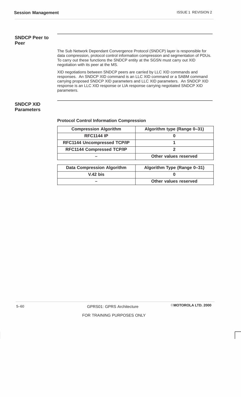
ISSUE 1 REVISION 2Session Management
�MOTOROLA LTD. 2000GPRS01: GPRS Architecture
FOR TRAINING PURPOSES ONLY
5–60
SNDCP Peer toPeer
The Sub Network Dependant Convergence Protocol (SNDCP) layer is responsible fordata compression, protocol control information compression and segmentation of PDUs.To carry out these functions the SNDCP entity at the SGSN must carry out XIDnegotiation with its peer at the MS.
XID negotiations between SNDCP peers are carried by LLC XID commands andresponses. An SNDCP XID command is an LLC XID command or a SABM commandcarrying proposed SNDCP XID parameters and LLC XID parameters. An SNDCP XIDresponse is an LLC XID response or LIA response carrying negotiated SNDCP XIDparameters.
SNDCP XIDParameters
Protocol Control Information Compression
Compression Algorithm Algorithm type (Range 0–31)
RFC1144 IP 0
RFC1144 Uncompressed TCP/IP 1
RFC1144 Compressed TCP/IP 2
– Other values reserved
Data Compression Algorithm Algorithm Type (Range 0–31)
V.42 bis 0
– Other values reserved

ISSUE 1 REVISION 2 Session Management
�MOTOROLA LTD. 2000 GPRS01: GPRS Architecture
FOR TRAINING PURPOSES ONLY
5–61
SNDCP LLC LLC SNDCP
LL_XID_REQ
XID
XID
LL_XID_IND
LL_XID_CNF
LL_XID_REQ
ORIGINATOR RECEIVER

ISSUE 1 REVISION 2Session Management
�MOTOROLA LTD. 2000GPRS01: GPRS Architecture
FOR TRAINING PURPOSES ONLY
5–62
LLC Peer to Peer
During Attach, PDP context activation and modification, LLC may negotiate externaloperating XID parameters for a SAPI with its peer LLC.
Negotiation takes place by exchanging XID frames or PDUs containing the parametersuntil a mutually acceptable set of parameters are arrived at.
LLC negotiates XID parameters when an XID frame is received from an MS or during anAttach procedure to negotiate XID parameters for the signalling SAPI, or during PDPcontext activation when SNDCP may issue an XID request for LLC to negotiate SNDCPparameters. LLC may choose to include LLC XID parameters in the same message asthe SNDCP parameters.

ISSUE 1 REVISION 2 Session Management
�MOTOROLA LTD. 2000 GPRS01: GPRS Architecture
FOR TRAINING PURPOSES ONLY
5–63

ISSUE 1 REVISION 2Session Management
�MOTOROLA LTD. 2000GPRS01: GPRS Architecture
FOR TRAINING PURPOSES ONLY
5–64
GGSN – PDPContextActivation
PDUs from MS to external data networks are transferred via SGSN and GGSN. TheGPRS Tunnelling Protocol (GTP) is used between SGSN and GGSN. Tunnels arecreated between the SGSN and GGSN before PDUs can be transferred. Create PDPContext creates a tunnel between the SGSN and GGSN when the MS wants to sendPDUs to an external network. Creating a tunnel between the SGSN and GGSN involvescreating a PDP context at the SGSN and GGSN.
The SGSN sends a Create PDP Context Request message to the GGSN specified eitherin the MS Create PDP Request message or the GGSN address specified in thesubscriber parameters from the HLR or the default GGSN address specified in the SGSNconfiguration.
The Create PDP Context Request from the SGSN is validated by the GGSN. If theTunnel ID (TID) is a new PDP context then the GGSN creates a new PDP context withthe values specified. The GGSN, once a PDP context has been activated, returns aCreate PDP context response with a cause value to indicate the success of the function.

ISSUE 1 REVISION 2 Session Management
�MOTOROLA LTD. 2000 GPRS01: GPRS Architecture
FOR TRAINING PURPOSES ONLY
5–65
SGSN GGSN
Create PDP Context Request
CREATE NEW PDP CONTEXT FOR MS
(TLLI, QOS, END USER PDPREQ)
Create PDP Context Reponse
(Response Accepted)

ISSUE 1 REVISION 2Session Management
�MOTOROLA LTD. 2000GPRS01: GPRS Architecture
FOR TRAINING PURPOSES ONLY
5–66

�MOTOROLA LTD. 2000 GPRS01: GPRS Architecture
FOR TRAINING PURPOSES ONLY
i
Chapter 6
SGSN configuration parameters

ISSUE 1 REVISION 2
�MOTOROLA LTD. 2000GPRS01: GPRS Architecture
FOR TRAINING PURPOSES ONLY
ii

ISSUE 1 REVISION 2 Introduction to SGSN configuration parameters
�MOTOROLA LTD. 2000 GPRS01: GPRS Architecture
FOR TRAINING PURPOSES ONLY
6–1
Introduction to SGSN configuration parameters
Purpose of thischapter
The purpose of this chapter is to provide reference information for SGSN configurationparameters.
How this chapteris structured
This chapter contains SGSN configuration parameters information, using the followingstructure to present that information:
� An introduction to the chapter and the chapter structure.
� Details of the MIB structure identifying the available SGSN objects.
� Parameter tables detailing the parameters available for each SGSN configurationobject.
� Reference diagrams, and explanations, of the purpose of the parameters.
� Data sheets containing information on the individual statistics identified in theattributes tables.
This information may be structured differently for training purposes
NOTE

ISSUE 1 REVISION 2Introduction to SGSN configuration parameters
�MOTOROLA LTD. 2000GPRS01: GPRS Architecture
FOR TRAINING PURPOSES ONLY
6–2
SGSN OIDstructure
Figure 6-1 illustrates the SGSN OID structure, with the emphasis on the configurationmanagement branch of the structure.
Sig
(3)
(1)
mot-gprs-sgsn
(1)
(2) Tx
(3)
(4) Meter
(5) Perf
(6) SW
(7) HA
(8) Op
(9) OAMP
System
SM
(2) SNDCP
(3) LLC
(4) BSSGP
(5) NS
(1)
GTP
GMM
(1) Params
(2) Tables
(1) E1 Link
FrameRelay
(5) NsvcFrPvc
(8) Nse
(12) NseNsvc
RaiNsei
(1)
(8)
(2)
GbLoadShareTransact
Figure 6-1 SGSN OID structure

ISSUE 1 REVISION 2 Introduction to SGSN configuration parameters
�MOTOROLA LTD. 2000 GPRS01: GPRS Architecture
FOR TRAINING PURPOSES ONLY
6–3
Parameter Tables
Details of the parameters available for each configuration management object can befound in the following tables:
Table 6-1 System
Table 6-2 Tx – SM
Table 6-3 Tx – SNDCP
Table 6-4 TX – LLC
Table 6-5 TX – BSSGP
Table 6-6 TX – NS Params
Table 6-7 Tx – NS Tables FrameRelay
Table 6-8 NSVC
Table 6-9 BVC
Table 6-10 Cell-BVC
Table 6-11 Sig – GTP
Table 6-12 Sig – GMM
Table 6-13 Sig – PlaneInformation
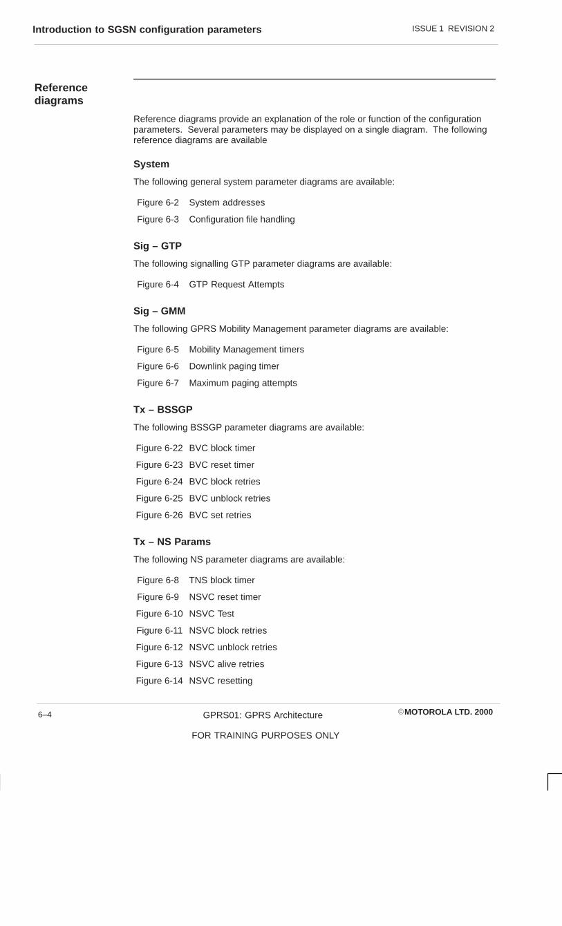
ISSUE 1 REVISION 2Introduction to SGSN configuration parameters
�MOTOROLA LTD. 2000GPRS01: GPRS Architecture
FOR TRAINING PURPOSES ONLY
6–4
Referencediagrams
Reference diagrams provide an explanation of the role or function of the configurationparameters. Several parameters may be displayed on a single diagram. The followingreference diagrams are available
System
The following general system parameter diagrams are available:
Figure 6-2 System addresses
Figure 6-3 Configuration file handling
Sig – GTP
The following signalling GTP parameter diagrams are available:
Figure 6-4 GTP Request Attempts
Sig – GMM
The following GPRS Mobility Management parameter diagrams are available:
Figure 6-5 Mobility Management timers
Figure 6-6 Downlink paging timer
Figure 6-7 Maximum paging attempts
Tx – BSSGP
The following BSSGP parameter diagrams are available:
Figure 6-22 BVC block timer
Figure 6-23 BVC reset timer
Figure 6-24 BVC block retries
Figure 6-25 BVC unblock retries
Figure 6-26 BVC set retries
Tx – NS Params
The following NS parameter diagrams are available:
Figure 6-8 TNS block timer
Figure 6-9 NSVC reset timer
Figure 6-10 NSVC Test
Figure 6-11 NSVC block retries
Figure 6-12 NSVC unblock retries
Figure 6-13 NSVC alive retries
Figure 6-14 NSVC resetting

ISSUE 1 REVISION 2 Introduction to SGSN configuration parameters
�MOTOROLA LTD. 2000 GPRS01: GPRS Architecture
FOR TRAINING PURPOSES ONLY
6–5
Tx – NS Tables
The following NS parameter diagrams are available:
Figure 6-15 Gb channel Id
Figure 6-16 SGSN WAN terminations
Figure 6-17 Frame Relay Status Enquiry
Figure 6-18 Gb interface error monitoring
Figure 6-19 NSVCI mapping
Figure 6-20 NSVC Link Id
Figure 6-21 Committed Information Rate

ISSUE 1 REVISION 2Configuration parameter tables
�MOTOROLA LTD. 2000GPRS01: GPRS Architecture
FOR TRAINING PURPOSES ONLY
6–6
Configuration parameter tables
Introduction toconfigurationparameter tables
This section of the manual details the parameters available for each SGSN configurationobject. The parameters available for each object are identified in individual object tables.
Systemparameters
The following table lists the SGSN general system parameters:
Table 6-1 SGSN general system parameters
OIDnumber
parameter
1 sgsnIpAddress
2 sgsnOMC–IpAddress
3 sgsnDefaultAPN
4 sgsnVersion
5 sgsnNetwork OperatorId–MCC
6 sgsnNetworkOperatorId-MNC
7 sgsnDiagConfigFileName
8 sgsnDumpConfigFileName
9 sgsnLoadConfigFileName
10 sgsnLoggingState
11 sgsnTracingState
SessionManagementparameters
The following table lists the SGSN transmit function Session Management parameters:
Table 6-2 SGSN Tx Session Management parameters
OIDnumber
parameter
1 sgsnMaxActivePDP-Context–PerIMSI

ISSUE 1 REVISION 2 Configuration parameter tables
�MOTOROLA LTD. 2000 GPRS01: GPRS Architecture
FOR TRAINING PURPOSES ONLY
6–7
SNDCPparameters
The following table lists the SGSN transmit function SNDCP parameters:
Table 6-3 SGSN Tx SNDCP parameters
OIDnumber
parameter
1 sgsnSNDCP–VersionNum
2 sgsnSNDCP–DataCompressionAlgorithm
3 sgsnNDCP–HeaderCompressionAlgorithm
4 sgsnNDCP–CompressionDirection
5 sgsnNDCP–MaxCompressionCodewords
6 sgsnNDCP–MaxCodewordLength
7 sgsnNDCP–CompressorShared
LLC parameters
The following table lists the SGSN transmit function LLC parameters:
Table 6-4 SGSN Tx LLC parameters
OIDnumber
parameter
1 sgsnLLC-VersionNum
BSSGPparameters
The following table lists the SGSN transmit function BSSGP parameters:
Table 6-5 SGSN Tx BSSGP parameters
OIDnumber
parameter
1 sgsnBSSGP-T1
2 sgsnBSSGP-T2
3 sgsnBSSGP-Bvc-BlockRetries
4 sgsnBSSGP-Bvc-UnblockRetries
5 sgsnBSSGP-Bvc-ResetRetries

ISSUE 1 REVISION 2Configuration parameter tables
�MOTOROLA LTD. 2000GPRS01: GPRS Architecture
FOR TRAINING PURPOSES ONLY
6–8
NS parameters
The following table lists the SGSN transmit function NS parameters:
Table 6-6 SGSN Tx NS parameters
OIDnumber
parameter
1 sgsnNS-TnsBlockTimer
2 sgsnNS-TnsResetTimer
3 sgsnNS-TnsTestInterval
4 sgsnNS-TnsAliveTimer
5 sgsnNS-BlockRetries
6 sgsnNS-UnblockRetries
7 sgsnNS-AliveRetries
8 sgsnNS-ResetPeriod
NS Frame Relaytable parameters
The following table lists the SGSN transmit function NS Frame Relay table parameters:
Table 6-7 SGSN Tx NS Frame Relay table parameters
OIDnumber
parameter
1 sgsnGb–FRRowStatus
2 sgsnGb–FRLinkId
3 sgsnGb–FRBearerChannelId
4 sgsnGb–FRDTE-DCE
5 sgsnGb–FRLMI-DLCI
6 sgsnGb–FRLMI-Std
7 sgsnGb–FRLMI-STDConform
8 sgsnGb–FRT391
9 sgsnGb–FRT392
10 sgsnGb–FRN391
11 sgsnGb–FRN392
12 sgsnGb–FRN393
13 sgsnGb–FRTimeSlot
14 sgsnGb–FR–EndTimeslot
15 sgsnGb-FR-MaxFrame
16 sgsnGb-FR-BitMask
17 sgsnGb-FR-FramingFormat
18 sgsnGb-FR-Encoding

ISSUE 1 REVISION 2 Configuration parameter tables
�MOTOROLA LTD. 2000 GPRS01: GPRS Architecture
FOR TRAINING PURPOSES ONLY
6–9
OIDnumber
parameter
19 sgsnGb–FR–LineBuildOut
20 sganGb-FR-Clocking
NS NsvcFrPvctable parameters
The following table lists the SGSN transmit function NS NsvcFrPvc table parameters:
Table 6-8 SGSN Tx NS NSVCFrPvc table parameters
OIDnumber
parameter
1 sgsnGb–NSVC-RowStatus
2 sgsnGb–NSVC-NSVCI
3 sgsnGb–NSVC-DLCI
4 sgsnGb–NSVC-LinkId
5 sgsnGb–NSVC-BearerChannelId
6 sgsnGb–NSVC-Frpvc-CIR
7 sgsnGb–NSVC-Frpvc-Bc
8 sgsnGb–NSVC-Frpvc-Be
9 sgsnGb–NSVC-Frpvc-StepCount
10 sgsnGb–NSVC-Frpvc-FlowStyle
BVC tableparameters
The following table lists the SGSN transmit function BVC table parameters:
Table 6-9 SGSN Tx NS table parameters
OIDnumber
parameter
1 sgsnGb–BVC–NseNsvcRowStatus
2 sgsnGb–BVC–BVCI
3 sgsnGb–BVC–BCVI–Type
4 sgsnGb–BVC–NSVCI
5 sgsnGb-BVC–SigBVCI

ISSUE 1 REVISION 2Configuration parameter tables
�MOTOROLA LTD. 2000GPRS01: GPRS Architecture
FOR TRAINING PURPOSES ONLY
6–10
Cell-PVCparameters
The following table lists the SGSN transmit function Cell-BVC table parameters:
Table 6-10 SGSN Cell-BVC parameters
OIDnumber
parameter
1 sgsnGb-Cell-BVC-Rowstatus
2 sgsnGb-Cell-BVC-MCC
3 sgsnGb-Cell-BVC-MNC
4 sgsnGb-Cell-BVC-LAC
5 sgsnGb-Cell-BVC-CI
6 sgsnGb-Cell-BVC-PTP-BVCI
Signalling GTPparameters
The following table lists the SGSN signalling GTP parameters:
Table 6-11 SGSN signalling GTP parameters
OIDnumber
parameter
1 sgsnGTP-N3RequestAttempts
Signalling GPRSMobilityManagementparameters
The following table lists the SGSN signalling GPRS Mobility Management parameters:
Table 6-12 SGSN signalling GPRS Mobility Management parameters
OIDnumber
parameter
1 sgsnStandbyTimer
2 sgsnReadyTimer
3 sgsnDnLinkPagingTimer
4 sgsnMaxPagingAttempts
5 sgsnPeriodicRAU-Timer

ISSUE 1 REVISION 2 Configuration parameter tables
�MOTOROLA LTD. 2000 GPRS01: GPRS Architecture
FOR TRAINING PURPOSES ONLY
6–11
Plane Controlparameters
The following table lists the SGSN signalling plane control table parameters:
Table 6-13 Plane Control parameters
OIDnumber
parameter
1 sgsnSigPlaneInfoRowStatus
2 sgsnSigPlaneInfo-MCC
3 sgsnSigPlaneInfo-MNC
4 sgsnSigPlaneInfo-LAC
5 sgsnSigPlaneInfo-CI
6 sgsnSigPlaneInfo-RAC
7 sgsnSigPlaneInfo-BVC

ISSUE 1 REVISION 2System parameter diagrams
�MOTOROLA LTD. 2000GPRS01: GPRS Architecture
FOR TRAINING PURPOSES ONLY
6–12
System parameter diagrams
Systemaddresses
The following diagram identifies the relationship of the system addresses of the SGSNconfiguration parameters. The sgsnIpAddress parameter specifies the logical IPaddress of the OAMP Agent within an SGSN. The sgsnOmcIpAddress parameterspecifies the IP address of the OMC-G for routing SNMP commands.
OMC-G
IP Address = sgsnOmcIpAddress
IP Address = sgsnIpAddress
Commhub
OAMP Agent
SGSN
Figure 6-2 System addresses

ISSUE 1 REVISION 2 System parameter diagrams
�MOTOROLA LTD. 2000 GPRS01: GPRS Architecture
FOR TRAINING PURPOSES ONLY
6–13
Configuration filehandling
The following diagram details how configuration files are handled within the GSN.System parameters (sgsnDiagConfigFileName and sgsnDumpConfigFileName )create a file name, or specify one that already exists, for storage of configurationinformation for diagnostic or archive (dump) purposes.
The sgsnLoadConfigFileName parameter creates a file name, or specifies one thatalready exists, for use when loading a configuration file.
OMC-G
Interface
ConfigurationData Store
GSN OAMP Agent
SNMP
GSN Sub Agent
SGSN Application
SNMPConfiguration
Data Store
Figure 6-3 Configuration file handling

ISSUE 1 REVISION 2sgsnIpAddress
�MOTOROLA LTD. 2000GPRS01: GPRS Architecture
FOR TRAINING PURPOSES ONLY
6–14
sgsnIpAddress
Description
This parameter identifies the IP address of a specific SGSN in a network.
Each SGSN has multiple IP addresses internally. The address defined here is the oneused by the OMC-G, that is, this is where the SGSN agent is running.
This parameter is initialized from /etc/hosts file using alias host name oamphost
Attributes
Value type Integer IP Address x.x.x.x
Valid range x = 0 to 255
Default value 0.0.0.0
Dependencies
Access read only
Status mandatory
Format
dot format, x.x.x.x
where:
0 <= x <= 255
Example
References

ISSUE 1 REVISION 2 sgsnOMC-IpAddress
�MOTOROLA LTD. 2000 GPRS01: GPRS Architecture
FOR TRAINING PURPOSES ONLY
6–15
sgsnOMC-IpAddress
Description
This parameter identifies the IP address of the managing OMC-G.
This parameter is initialized from /etc/hosts file using alias host name omcghost
Attributes
Value type Integer
Valid range 0 to 255
Default value 0.0.0.0
Dependencies
Access read only
Status mandatory
Format
dot format, x.x.x.x
where:
0 <= x <= 255
Example
References

ISSUE 1 REVISION 2sgsnDefaultAPN
�MOTOROLA LTD. 2000GPRS01: GPRS Architecture
FOR TRAINING PURPOSES ONLY
6–16
sgsnDefaultAPN
Description
This parameter identifies the default APN that the SGSN uses, according to the APNselection algorithm specified in GSM 03.60 v6.3.1.
The APN requirement is defined in GSM 03.03.
This parameter contains only the Network Identifier, it does not contain the APN OperatorIdentifier.
Attributes
Value type
Valid range 0 to 63
Default value
Dependencies
Access read - write
Status mandatory
Format
Example
References
GSM 03.60 v6.3.1.
GSM 03.03

ISSUE 1 REVISION 2 sgsnVersion
�MOTOROLA LTD. 2000 GPRS01: GPRS Architecture
FOR TRAINING PURPOSES ONLY
6–17
sgsnVersion
Description
This parameter identifies the software version that runs on the currently identified SGSN.
Attributes
Value type hexidecimal
Valid range 00 to ff (using lower case letters)
Default value GSN00.00.00.00
Dependencies
Access read only
Status mandatory
Format
GSN<system>.<major>.<minor>.<patch>
where:
<system> : GPRS system release number<major> : GSN major release number<minor> : GSN minor release number<patch> : GSN patch level
Example
References

ISSUE 1 REVISION 2sgsnNetworkOperatorId-MCC
�MOTOROLA LTD. 2000GPRS01: GPRS Architecture
FOR TRAINING PURPOSES ONLY
6–18
sgsnNetworkOperatorId-MCC
Description
This parameter is the Network Operator Identification - Mobile Country Code.
Attributes
Value type decimal
Valid range 0 to 9 (in ASCII format)
Default value 000
Dependencies None
Access read - write
Status mandatory
Format
3 decimal digits in ASCII format, with 0 padded at the front.
Example
References
CCITT Rec E.212 Annex A

ISSUE 1 REVISION 2 sgsnNetworkOperatorId-MNC
�MOTOROLA LTD. 2000 GPRS01: GPRS Architecture
FOR TRAINING PURPOSES ONLY
6–19
sgsnNetworkOperatorId-MNC
Description
This parameter is the Network Operator Identification - Mobile Network Code.
Attributes
Value type decimal
Valid range 0 to 9 (in ASCII format)
Default value 00
Dependencies None
Access read - write
Status mandatory
Format
2 decimal digits in ASCII format, with 0 padded at the front.
Example
References
GSM 03.03 v6.1.0

ISSUE 1 REVISION 2sgsnDiagConfigFileName
�MOTOROLA LTD. 2000GPRS01: GPRS Architecture
FOR TRAINING PURPOSES ONLY
6–20
sgsnDiagConfigFileName
Description
This parameter is the full path name of a configuration file to be sanity checked.
When this variable is SET the GSN checks whether the file exists or not. If not, the GSNcreates the file.
Attributes
Value type
Valid range 0 to 256
Default value
Dependencies
Access read - write
Status mandatory
Format
Example
References

ISSUE 1 REVISION 2 sgsnDumpConfigFileName
�MOTOROLA LTD. 2000 GPRS01: GPRS Architecture
FOR TRAINING PURPOSES ONLY
6–21
sgsnDumpConfigFileName
Description
This parameter is the full path name of a configuration file used for a configuration dump.
The SGSN creates the file if it does not already exist.
Attributes
Value type
Valid range 0 to 256
Default value
Dependencies
Access read - write
Status mandatory
Format
Example
References

ISSUE 1 REVISION 2sgsnLoadConfigFileName
�MOTOROLA LTD. 2000GPRS01: GPRS Architecture
FOR TRAINING PURPOSES ONLY
6–22
sgsnLoadConfigFileName
Description
This parameter is the full path name of a configuration file used for SGSN configurationsynchronization, or for configuration through a configuration file.
Attributes
Value type
Valid range 0 to 256
Default value
Dependencies
Access read - write
Status mandatory
Format
Example
References

ISSUE 1 REVISION 2 sgsnLoggingState
�MOTOROLA LTD. 2000 GPRS01: GPRS Architecture
FOR TRAINING PURPOSES ONLY
6–23
sgsnLoggingState
DescriptionThis parameter is used to specify the current level of SGSN logging.
Disable(0) : Default, only the traps are logged.
EnableLevel1(1) : Enable, INFO level.
� Provide supplementary information to an alarm.
� Security alert (for example: unauthorised access).
� Startup/shutdown logging.
� Failure of external components (for example: BSS and GGSN - fromthe perspective of the SGSN).
EnableLevel2(2) : Enable, Medium Verbose level.
� GPRS signalling failure (for example: Attach Reject, Activate Reject,Deactivate Reject).
� MS protocol failure (LLC, SNDCP, MM, SM).
EnableLevel3(3) : Enable, Verbose level.
� All signalling messages (L3MM. GAP, GTP), except the ones logged atthe Medium Verbose level.
� LLC reset.
EnableLevel4(4) : Enable, DEBUG level.
� Detailed logging of internal events, enabling support staff to performdebugging (for example: sequence of function calls, value of variableetc). Logs generated at this level are not expected to be fully understood by the operators.
Enabling the logging at a higher level automatically enables the logging at all lower levels.
Attributes
Value type Integer
Valid range 0 to 4
Default value 0
Dependencies
Access read - write
Status mandatory
Format
Example
References

ISSUE 1 REVISION 2sgsnTracingState
�MOTOROLA LTD. 2000GPRS01: GPRS Architecture
FOR TRAINING PURPOSES ONLY
6–24
sgsnTracingState
Description
This parameter is used to enable/disable SGSN tracing. (For R0 either all protocoltraces are enabled or all disabled).
Disable(0)
Enable(1)
Attributes
Value type Integer
Valid range 0 or 1
Default value 0
Dependencies
Access read - write
Status mandatory
Format
Example
References

ISSUE 1 REVISION 2 Signalling GTP parameter diagrams
�MOTOROLA LTD. 2000 GPRS01: GPRS Architecture
FOR TRAINING PURPOSES ONLY
6–25
Signalling GTP parameter diagrams
GTP RequestAttempts
The following diagram details the PDP Context Request message, which is repeated if noresponse is received during period T3 (mandatory timer). ThesgsnGtpN3RequestAttempts parameter is used to set the number of times (N3counter) that the request is repeated, each request lasting T3.
repeated N3 times
SGSN GGSN
Create PDP Context RequestT3
sgsnGTPN3RequestAttempts
Create PDP Context Request
Create PDP Context Request
Figure 6-4 GTP Request Attempts

ISSUE 1 REVISION 2sgsnGTP-N3RequestAttempts
�MOTOROLA LTD. 2000GPRS01: GPRS Architecture
FOR TRAINING PURPOSES ONLY
6–26
sgsnGTP-N3RequestAttempts
Description
The counter N3-REQUESTS holds the maximum number of attempts made by theSGSN to send a signalling request message.
Attributes
Value type integer
Valid range 1 to 5
Default value 3
Dependencies
Access read - write
Status mandatory
Format
Example
References
GSM 09.60 v5.0.0

ISSUE 1 REVISION 2 GPRS Mobility Management parameter diagrams
�MOTOROLA LTD. 2000 GPRS01: GPRS Architecture
FOR TRAINING PURPOSES ONLY
6–27
GPRS Mobility Management parameter diagrams
MobilityManagementtimers
The following diagram details the Mobility Management states of the mobile subscriber(MS).
The Ready timer determines how long the MS remains in the Ready state. The MS isreturned to the Idle state if a Detach command is received during the timer period. If thetimer expires (reaches the preset value) the MS is placed into the Standby state. Thetimer is over-ridden, and the MS placed into the Standy mode, if a Force to Standbycommand or Abnormal condition occurs.
The Standby timer determines how long the MS remains in the Standby state. The MS isreturned to the Ready state if a PDU is received during the timer period. If the timerexpires the MS is returned to the Idle state.
IDLE
READY
STANDBY
StandbyTimerExpiry
GPRSAttach
GPRSDetach
PDUReception
Ready Timer ExpiryorForce to StandbyorAbnormal Condition
sgsnStanbyTimer–1 = DeactivatedValid Range: 6 – 186 (in multiplesof 6)
sgsnReadyTimer–1 = Deactivated0 = Force to StandbyValid Range: 2 – 1800
Figure 6-5 Mobility Management timers

ISSUE 1 REVISION 2GPRS Mobility Management parameter diagrams
�MOTOROLA LTD. 2000GPRS01: GPRS Architecture
FOR TRAINING PURPOSES ONLY
6–28
Downlink pagingtimer
The following diagram details PDU paging messages used to determine the location ofthe recipient Mobile Subscriber (MS) in the routing area. The sgsnDnLinkPagingTimerparameter determines the value of the downlink paging timer, T3313. The timer governsthe waiting period between a PSPDU paging message being sent to all BSSs and theexpected Page Replied Indication response.
GGSN
Downlink PDU
Page–Ind
BSS#1
BSS#2
Page PSPDU
LLC FRAME
Page Replied –IND
SGSN TF
SGSN CF
StartT3313
StopT3313
MS
sgsnDnLinkPagingTimerRange 3 – 15 Secs
Default 8
Figure 6-6 Downlink paging timer

ISSUE 1 REVISION 2 GPRS Mobility Management parameter diagrams
�MOTOROLA LTD. 2000 GPRS01: GPRS Architecture
FOR TRAINING PURPOSES ONLY
6–29
Maximum pagingattempts
The following diagram details PDU paging messages. The PSPDU paging message issent to all BSS in a routing area and is repeated if a Page Replied Indicator response isnot received from the BSS before the expiry of T3313. The sgsnMaxPagingAttemptsparameter determines the number of times the paging attempt is repeated.
Page–Ind
Page PSPDU
SGSN TF SGSN CF
StartT3313
sgsnMaxPagingAttemptsRange 1 – 5Default 2
Page PSPDU
forMaxPagingAttempts
BSS#1
BSS#2
BSS#1
BSS#2
Figure 6-7 Maximum paging attempts


ISSUE 1 REVISION 2Network Service parameter diagrams
�MOTOROLA LTD. 2000GPRS01: GPRS Architecture
FOR TRAINING PURPOSES ONLY
6–30
Network Service parameter diagrams
NSVC block timer
The following diagram details NS block and unblock PDUs. The sgsnNsTnsBlockTimerparameter determines the period of the TNS block timer, which controls the NSVCblocking and unblocking procedures.
PCU SGSN
NS Block or Unblock PDU TNS Block
sgsnNsTnsBlockTimerRange 1 – 30 Secs
Default 3
NS Block or Unblock Ack PDU
Figure 6-8 NSVC block timer

ISSUE 1 REVISION 2 Network Service parameter diagrams
�MOTOROLA LTD. 2000 GPRS01: GPRS Architecture
FOR TRAINING PURPOSES ONLY
6–31
NSVC reset timer
The following diagram details NS reset PDUs. The sgsnNsTnsResetTimer parameterdetermines the period of the NSVC reset timer. The timer is started when the reset PDUis sent and stopped on receipt of the reset acknowledgement.
The NSVC Reset forces peer entities to a known (blocked) state. Once both entities areat the same state the NSVC unblock procedures can be carried out to bring the NSVCinto service.
PCU SGSN
NS Reset PDU TNS Reset
sgsnNsTnsResetTimerRange 1 – 60 Secs
Default 3
NS Reset Ack PDU
Figure 6-9 NSVC reset timer

ISSUE 1 REVISION 2Network Service parameter diagrams
�MOTOROLA LTD. 2000GPRS01: GPRS Architecture
FOR TRAINING PURPOSES ONLY
6–32
NSVC Test
The following diagram details the Network Service Test procedure. ThesgsnNsTnsAliveTimer parameter controls the NSVC test procedure. The timer isstarted when an NS alive PDU is sent to a peer entity, and is stopped on receipt of an NSAlive Acknowledge PDU.
The sgsnNsTnsTestInterval parameter governs the time between NSVC tests. Thetest interval is started on receipt of the NS alive Acknowledge PDU, and when it expiresthe next NSVC test is started.
PCU SGSN
NS Alive PDU
TNS Alive
sgsnNsTnsTestIntervalRange 1 – 60 Secs
Default 10
NS Alive Ack PDU
TNS TestInterval
TNS TestInterval
sgsnNsTnsAliveTimerRange 1 – 60 Secs
Default 3
Figure 6-10 NSVC Test
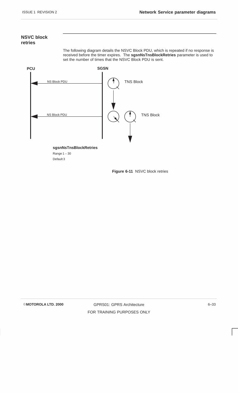
ISSUE 1 REVISION 2 Network Service parameter diagrams
�MOTOROLA LTD. 2000 GPRS01: GPRS Architecture
FOR TRAINING PURPOSES ONLY
6–33
NSVC blockretries
The following diagram details the NSVC Block PDU, which is repeated if no response isreceived before the timer expires. The sgsnNsTnsBlockRetries parameter is used toset the number of times that the NSVC Block PDU is sent.
PCU SGSN
NS Block PDU TNS Block
sgsnNsTnsBlockRetriesRange 1 – 30
Default 3
NS Block PDU TNS Block
Figure 6-11 NSVC block retries

ISSUE 1 REVISION 2Network Service parameter diagrams
�MOTOROLA LTD. 2000GPRS01: GPRS Architecture
FOR TRAINING PURPOSES ONLY
6–34
NSVC unblockretries
The following diagram details the NSVC Unblock PDU, which is repeated if no responseis received before the timer expires. The sgsnNsTnsUnblockRetries parameter is usedto set the number of times that the NSVC Unblock PDU is sent.
PCU SGSN
NS Unblock PDU TNS Unblock
sgsnNsTnsUnblockRetriesRange 1 – 30
Default 3
NS Unblock PDU TNS Unblock
Figure 6-12 NSVC unblock retries
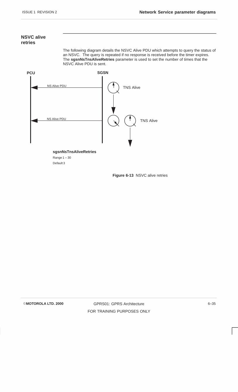
ISSUE 1 REVISION 2 Network Service parameter diagrams
�MOTOROLA LTD. 2000 GPRS01: GPRS Architecture
FOR TRAINING PURPOSES ONLY
6–35
NSVC aliveretries
The following diagram details the NSVC Alive PDU which attempts to query the status ofan NSVC. The query is repeated if no response is received before the timer expires.The sgsnNsTnsAliveRetries parameter is used to set the number of times that theNSVC Alive PDU is sent.
PCU SGSN
NS Alive PDU TNS Alive
sgsnNsTnsAliveRetriesRange 1 – 30
Default 3
NS Alive PDU TNS Alive
Figure 6-13 NSVC alive retries

ISSUE 1 REVISION 2Network Service parameter diagrams
�MOTOROLA LTD. 2000GPRS01: GPRS Architecture
FOR TRAINING PURPOSES ONLY
6–36
NSVC resetting
The following diagram details the NSVC resetting procedure. ThesgsnNsTnsResetPeriod parameter sets the period for the NSVC reset procedure.During this period NS Reset PDUs are sent to the peer entity, governed by the ResetTimer. Rest PDUs are sent until a rest acknowledgement is received or the Reset Periodexpires.
For this procedure to function the Rest Period must be set to a greater value than that ofthe Reset Timer.
PCU SGSN
NS Reset PDU TnsResetTimer
sgsnNsTnsResetPeriodRange 1 – 1000 Secs
Default 3
NS Reset PDU TnsResetTimerResetPeriod
ResetPeriod > TnsResetTimer
Figure 6-14 NSVC resetting

ISSUE 1 REVISION 2 sgsnNS-TnsBlockTimer
�MOTOROLA LTD. 2000 GPRS01: GPRS Architecture
FOR TRAINING PURPOSES ONLY
6–37
sgsnNS-TnsBlockTimer
Description
This parameter is the timer, in seconds, that guards the NS blocking and unblockingprocedures.
The blocking or unblocking message is attempted every sgsnNsTnsBlockTimer seconds,until the peer NS acknowledges or the number of retries (sgsnNsBlockRetries orsgsnNsUnblockRetries ) for the procedure is completed.
Attributes
Value type integer
Valid range 1 to 30
Default value 3
Dependencies
Access read - write
Status mandatory
Format
Example
References

ISSUE 1 REVISION 2sgsnNS-TnsResetTimer
�MOTOROLA LTD. 2000GPRS01: GPRS Architecture
FOR TRAINING PURPOSES ONLY
6–38
sgsnNS-TnsResetTimer
Description
This parameter is the timer, in seconds, that guards the NS reset procedure.
The reset is sent every sgsnNS–TnsResetTimer seconds, until the peer NSacknowledges or the sgsnNsResetPeriod expires. It must be less thansgsnNsResetPeriod .
Attributes
Value type integer
Valid range 1 to 60
Default value 3
Dependencies
Access read - write
Status mandatory
Format
Example
References

ISSUE 1 REVISION 2 sgsnNS-TnsTestInterval
�MOTOROLA LTD. 2000 GPRS01: GPRS Architecture
FOR TRAINING PURPOSES ONLY
6–39
sgsnNS-TnsTestInterval
Description
This parameter indicates the periodicity of the NS-VC test procedure, in seconds. It mustbe greater than sgsnNS-TnsAliveTimer .
Attributes
Value type integer
Valid range 1 to 60
Default value 10
Dependencies
Access read - write
Status mandatory
Format
Example
References

ISSUE 1 REVISION 2sgsnNS-TnsAliveTimer
�MOTOROLA LTD. 2000GPRS01: GPRS Architecture
FOR TRAINING PURPOSES ONLY
6–40
sgsnNS-TnsAliveTimer
Description
This parameter is the timer, in seconds, that guards the NS-VC test procedure.
The NsAlive PDU is sent to the peer every sgsnNsTnsAliveTimer seconds, until the peeracknowledges or the number of retries (sgsnNsAliveRetries ) is completed. It must beless than the sgsnNsTnsTestInterval .
Attributes
Value type integer
Valid range 1 to 30
Default value 3
Dependencies
Access read - write
Status mandatory
Format
Example
References
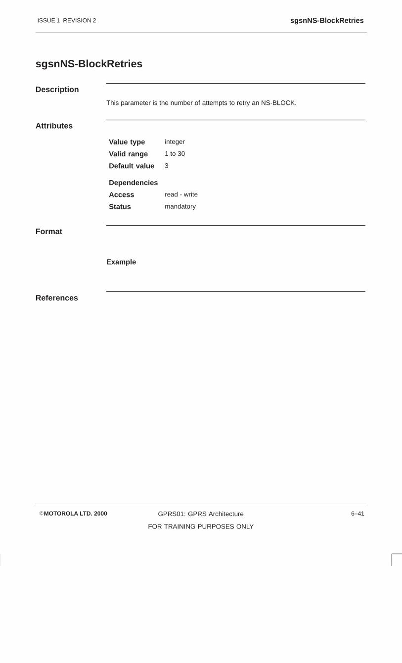
ISSUE 1 REVISION 2 sgsnNS-BlockRetries
�MOTOROLA LTD. 2000 GPRS01: GPRS Architecture
FOR TRAINING PURPOSES ONLY
6–41
sgsnNS-BlockRetries
Description
This parameter is the number of attempts to retry an NS-BLOCK.
Attributes
Value type integer
Valid range 1 to 30
Default value 3
Dependencies
Access read - write
Status mandatory
Format
Example
References

ISSUE 1 REVISION 2sgsnNsUnblockRetries
�MOTOROLA LTD. 2000GPRS01: GPRS Architecture
FOR TRAINING PURPOSES ONLY
6–42
sgsnNsUnblockRetries
Description
This parameter is the number of attempts to retry an NS-UNBLOCK.
Attributes
Value type integer
Valid range 1 to 30
Default value 3
Dependencies
Access read - write
Status mandatory
Format
Example
References

ISSUE 1 REVISION 2 sgsnNS-AliveRetries
�MOTOROLA LTD. 2000 GPRS01: GPRS Architecture
FOR TRAINING PURPOSES ONLY
6–43
sgsnNS-AliveRetries
Description
This parameter is the number of attempts to retry the NS-VC test procedure.
Attributes
Value type integer
Valid range 1 to 30
Default value 3
Dependencies
Access read - write
Status mandatory
Format
Example
References

ISSUE 1 REVISION 2sgsnNS-ResetPeriod
�MOTOROLA LTD. 2000GPRS01: GPRS Architecture
FOR TRAINING PURPOSES ONLY
6–44
sgsnNS-ResetPeriod
Description
This parameter is the period, in seconds, during which reset is attempted. It must begreater than sgsnNsTnsResetTimer .
Attributes
Value type integer
Valid range 1 to 1000
Default value 30
Dependencies
Access read - write
Status mandatory
Format
Example
References

ISSUE 1 REVISION 2 sgsnStandbyTimer
�MOTOROLA LTD. 2000 GPRS01: GPRS Architecture
FOR TRAINING PURPOSES ONLY
6–45
sgsnStandbyTimer
Description
T3315: The value of the Standby Timer in minutes.
As the timer will be encoded in decihours (1/10 of an hour) the unit of increment should be6 minutes. If the value X of the timer is not set to a multiple of 6, it will be truncated. Thetruncated value Y is the nearest multiple of 6, with:
X–6 < Y < X
If truncation occurs, while value Y will be used by the GSN applications, value X is stillreturned in response to a GET request on this variable.
The truncated value of sgsnStandbyTimer should always be greater than thetruncated value of sgsnPeriodicRAU-Timer by a multiple of 6.
Attributes
Value type Integer
Valid range –1 : indicates deactivated6 - 186 : actual timer value
Default value 60
Dependencies
Access read - write
Status mandatory
Format
Example
References
GSM 04.08 v5.6.2, CR A265

ISSUE 1 REVISION 2sgsnReadyTimer
�MOTOROLA LTD. 2000GPRS01: GPRS Architecture
FOR TRAINING PURPOSES ONLY
6–46
sgsnReadyTimer
Description
T3314: The value of the Ready Timer in seconds.
The timer will be encoded in seconds or minutes with certain units of increment,depending on the value to be encoded.
From 2 to 60 seconds, the encoding will be in seconds with the unit of increment 2seconds. If the value X of the timer, in the range 2 - 60 seconds, is not set to a multipleof 2 it will be truncated. The truncated value Y is the nearest multiple of 2, with:
X–2 < Y < X
From 61 to 1800 seconds, the encoding will be in minutes with the unit of increment 60seconds (1 minute). If the value X of the timer, in the range 61 - 1800 seconds, is not setto a multiple of 60 it will be truncated. The truncated value Y is the nearest multiple of60, with:
X–60 < Y < X
If truncation occurs, while value Y will be used by the GSN applications, value X is stillreturned in response to a GET request on this variable.
Attributes
Value type Integer
Valid range –1 : indicates deactivated0 : indicates Force to Standby2 - 1800: actual timer value
Default value 32
Dependencies
Access read - write
Status mandatory
Format
Example
References
GSM 04.08 v5.6.2, CR A265 Rev 5

ISSUE 1 REVISION 2 sgsnDnLinkPagingTimer
�MOTOROLA LTD. 2000 GPRS01: GPRS Architecture
FOR TRAINING PURPOSES ONLY
6–47
sgsnDnLinkPagingTimer
Description
T3313: The value of the Downlink transfer paging Timer in seconds.
Attributes
Value type Integer
Valid range 3 to 15
Default value 8
Dependencies
Access read - write
Status mandatory
Format
Example
References
GSM 04.08 v5.6.2, CR A265 Rev 5

ISSUE 1 REVISION 2sgsnMaxPagingAttempts
�MOTOROLA LTD. 2000GPRS01: GPRS Architecture
FOR TRAINING PURPOSES ONLY
6–48
sgsnMaxPagingAttempts
Description
This parameter identifies the maximum number of attempts to page an MS.
Attributes
Value type Integer
Valid range 1 to 5
Default value 2
Dependencies
Access read - write
Status mandatory
Format
Example
References
GSM introduced.

ISSUE 1 REVISION 2 sgsnPeriodicRAU-Timer
�MOTOROLA LTD. 2000 GPRS01: GPRS Architecture
FOR TRAINING PURPOSES ONLY
6–49
sgsnPeriodicRAU-Timer
Description
T3312: The value of the Periodic RAU (Routing Area Update) Timer in minutes.
As the timer will be encode in decihours (1/10 of an hour) the unit of increment should be6 minutes. If the value X of the timer is not set to a multiple of 6, it will be truncated. Thetruncated value Y is the nearest multiple of 6, with:
X–6 < Y < X
If truncation occurs, while value Y will be used by the GSN applications, value X is stillreturned in response to a GET request on this variable.
The truncated value of sgsnPeriodicRAU-Timer should always be smaller than thetruncated value of sgsnStandbyTimer by a multiple of 6.
Attributes
Value type Integer
Valid range –1 : indicates deactivated6 - 180 : actual timer value
Default value 54
Dependencies
Access read - write
Status mandatory
Format
Example
References
GSM 04.08 v5.6.2, CR A562


ISSUE 1 REVISION 2NS Tables parameter diagrams
�MOTOROLA LTD. 2000GPRS01: GPRS Architecture
FOR TRAINING PURPOSES ONLY
6–50
NS Tables parameter diagrams
Gb channel Id
The following diagram details an E1 bearer channel. The Id of this channel can bespecified by use of the sgsnFrBearerChannelId parameter.
Range: 0 – 30
DLCI = 177 DLCI = 177
DLCI = 45DLCI = 45
Bearer Channel
sgsnFrBearerChannelId
Default 0
Figure 6-15 Gb channel Id

ISSUE 1 REVISION 2 NS Tables parameter diagrams
�MOTOROLA LTD. 2000 GPRS01: GPRS Architecture
FOR TRAINING PURPOSES ONLY
6–51
SGSN WANterminations
The following diagram provides SGSN WAN termination details. The SGSN has tofunction as Data Terminal Equipment (DTE) or Data Communications Equipment (DCE),depending on the type of WAN interface. The SGSN is set to function as DTE or DCE byuse of the sgsnFrDteDce parameter.
sgsnFrDteDce
BSS SGSNGb
DCEDTE
Direct Connection
Gb Gb
DTE DTE
Range: 0 = DCE
1 = DTE
FrameRelay
ConnectionBSS SGSN
Figure 6-16 SGSN WAN terminations

ISSUE 1 REVISION 2NS Tables parameter diagrams
�MOTOROLA LTD. 2000GPRS01: GPRS Architecture
FOR TRAINING PURPOSES ONLY
6–52
Frame RelayStatus Enquiry
The following diagram details the Frame Relay Status Enquiry procedure. ThesgsnFrT391 parameter sets the period between Status Enquiry messages being sentfrom the user to the network.
Timer T392 is started when the Status response is sent from the network to the user, andthe next Status Enquiry should arrive before the timer expires. Parameter sgsnFrT392sets the value of the timer.
The complete status enquiry procedure is governed by counter N391, which determinesthe number of Status Enquiries that have to be sent before a Full Status Enquiry is sent.Parameter sgsnFrN391 sets the value of the counter.
UserNetwork
Status EnquiryT391
Status Enquiry
Full Status Enquiry
N391
Status
Status
Full Status
sgsnFrT391Range: 5 – 29 SecsDefault 10
T392
sgsnFrT392Range: 6 – 30 Secs
Default 15
sgsnFrT392 > sgsnFrT391
sgsnFrN391Range: 1 – 255Default 6
Figure 6-17 Frame Relay Status Enquiry

ISSUE 1 REVISION 2 NS Tables parameter diagrams
�MOTOROLA LTD. 2000 GPRS01: GPRS Architecture
FOR TRAINING PURPOSES ONLY
6–53
Gb Interfaceerror monitoring
The following diagram details the Gb Interface error monitoring, used in conjunction withthe Status response timer T392. Counter N393 monitors the number of error events, andis incremented each time the timer expires or an invalid Status Enquiry is received.Counter N392 monitors the number of contiguous error events. Parameter sgsnFrN393sets the maximum number of error events to be counted, and parameter sgsnFrN392sets the number of contiguous error events to be counted.
N393
N392
T392
sgsnFrN392Range 1 – 10
Default 3
Network
sgsnFrN393Range 1 – 10
Default 4
No Status Enquiry
sgsnFrN392 <= sgsnFrN393
Figure 6-18 Gb interface error monitoring

ISSUE 1 REVISION 2NS Tables parameter diagrams
�MOTOROLA LTD. 2000GPRS01: GPRS Architecture
FOR TRAINING PURPOSES ONLY
6–54
NSVCI mapping
The following diagram details the mapping between protocol layers. In a Point to Pointconnection the NSVCI and DLCI have end to end significance. In an intermediate FrameRelay network only the NSVCI has end to end significance.
BSSGP
NSVCI
DLCI
NSVCI
DLCI DLCI
Chan ID Chan ID
sgsnNsvcFrPvcDLCI
Range: 16 – 991
Default 16
FrameRelay
NS
E1
BSSGP
NS
FrameRelay
E1
sgsnNsvcFrPvcNSVCI
Range: 1 – 65535
BSSGP
FrameRelay
NS
E1
BSSGP
FrameRelay
NS
E1
Figure 6-19 NSVCI mapping

ISSUE 1 REVISION 2 NS Tables parameter diagrams
�MOTOROLA LTD. 2000 GPRS01: GPRS Architecture
FOR TRAINING PURPOSES ONLY
6–55
NSVC Link Id
The following diagram details a NSVC Link. ParametersgsnNsvcFrPvcBearerChannelId specifies the identity of a bearer channel within thelink, and parameter sgsnNsvcFrPvcPhyLinkId specifies the identity of the bearer link.
Range: 0 – 30
Bearer Link
DLCI = 177
DLCI = 45
Bearer Channel 1
sgsnNsvcFrPvcBearerChannelId
Default 0
Bearer Channel 2
DLCI = 55
DLCI = 23
Range: 0 – 3
sgsnNsvcFrPvcPhyLinkId
Default 0
Figure 6-20 NSVC Link Id

ISSUE 1 REVISION 2NS Tables parameter diagrams
�MOTOROLA LTD. 2000GPRS01: GPRS Architecture
FOR TRAINING PURPOSES ONLY
6–56
CommittedInformation Rate
The following diagram provides details of the Committed Information Rate (CIR). TheCIR is effectively the amount of information that can be transferred over a given period,and is set by parameter sgsnNsvcFrPvcCIR . Information transferred at the CIR rate isguaranteed to be delivered.
Due to the burst nature of information transfer, the required transfer may exceed theguaranteed limit. An agreed excess, Bc, may be permitted but the information may beeligible for discard. The size of the excess is set using parameter sgsnNsvcFrPvcBc .
It is possible that the excess may also be insufficient. An additional amount, Be, may beagreed but the information is likely to be discarded on entry. The size of the additionalamount is set using parameter sgsnNsvcFrPvcBe .
Bc
1
2
3
4
CIR
T
Guaranteed
Discard Eligible
Discard OnEntryBc + Be
Bits
sgsnNsvcFrPvcCIR
Range 1 – 2048000
Default 1
sgsnNsvcFrPvcBc
Range: 1 – 2048000
Default 1
sgsnNsvcFrPvcBe
Range: 1 – 2048000
Default 0
Figure 6-21 Committed Information Rate

ISSUE 1 REVISION 2 sgsnGb-FR-Table
�MOTOROLA LTD. 2000 GPRS01: GPRS Architecture
FOR TRAINING PURPOSES ONLY
6–57
sgsnGb-FR-Table
Description
This table lists the Frame Relay Bearer Channels for this SGSN.
Row Creation: For the successful creation of a row in this table, the underlyingphysical E1/T1 links must have already been in service.
Row Deletion: If the Bearer Channel defined by the row is not being referenced byany rows in the sgsnGb-Nsvc-Table , it is allowed to be deleted.Any other attempt at deleting it should be rejected.
Row Update Currently, the software does not have provision to update individualentry values for a row after it has been created. Updates can onlybe achieved by deleting the existing row and then inserting a newrow containing the new values, through separate managementrequests.
Attributes
Value type
Valid range
Default value
Dependencies
Access not accessible
Status mandatory
Format
Example
References

ISSUE 1 REVISION 2sgsnGb-FR-Entry
�MOTOROLA LTD. 2000GPRS01: GPRS Architecture
FOR TRAINING PURPOSES ONLY
6–58
sgsnGb-FR-Entry
Description
This parameter defines an entry for a single Frame Relay Bearer Channel.
Attributes
Value type
Valid range
Default value
Dependencies
Access not accessible
Status mandatory
Format
sgsnFrameRelayEntry ::=
SEQUENCE{
sgsnGb-FRRowStatus GSN-RowStatus,
sgsnGb-FRLinkId INTEGER,
sgsnGb-FRBearerChannelId INTEGER,
sgsnGb-FRDTE-Dce INTEGER,
sgsnGb-FRLMI-DLCI INTEGER,
sgsnGb-FRLMI-STD INTEGER,
sgsnGb-FRLMI-STD-Conform INTEGER,
sgsnGb-FRT391 INTEGER,
sgsnGb-FRT392 INTEGER,
sgsnGb-FRN391 INTEGER,
sgsnGb-FRN392 INTEGER,
sgsnGb-FRN393 INTEGER,
sgsnGb-FRStartTimeSlot
sgsnGb-FR-EndTimeslot
sgsnGb-FR-MaxFrame
sgsnGb-FR-BitMask
sgsnGb-FR-FramingFormat
sgsnGb-FR-Encoding
sgsnGb-FR-LineBuildout
sgsnGb-FR-Clocking
INTEGER,
INTEGER
INTEGER
OCTET STRING
INTEGER
INTEGER
INTEGER
INTEGER
}

ISSUE 1 REVISION 2 sgsnGb-FR-Entry
�MOTOROLA LTD. 2000 GPRS01: GPRS Architecture
FOR TRAINING PURPOSES ONLY
6–59
Example
References

ISSUE 1 REVISION 2sgsnGb-FR-RowStatus
�MOTOROLA LTD. 2000GPRS01: GPRS Architecture
FOR TRAINING PURPOSES ONLY
6–60
sgsnGb-FR-RowStatus
Description
This parameter indicates the status of a table row.
Attributes
Value type
Valid range
Default value undefined
Dependencies
Access read - write
Status mandatory
Format
Example
References

ISSUE 1 REVISION 2 sgsnGb–FR-LinkId
�MOTOROLA LTD. 2000 GPRS01: GPRS Architecture
FOR TRAINING PURPOSES ONLY
6–61
sgsnGb–FR-LinkId
Description
This parameter is the identifier of the Frame Relay bearer E1 link, unique within anSGSN. It is used by the SGSN to identify the physical E1/T1 link for configuring theFrame Relay WAN interfaces.
Attributes
Value type integer
Valid range 0 to 3
Default value
Dependencies
Access read only
Status mandatory
Format
Example
References

ISSUE 1 REVISION 2sgsnGb-FR-BearerChannelId
�MOTOROLA LTD. 2000GPRS01: GPRS Architecture
FOR TRAINING PURPOSES ONLY
6–62
sgsnGb-FR-BearerChannelId
Description
This parameter is the identifier of the Bearer Channel, unique within the SGSN for R0,unique within an E1/T1 link in R1. It is used by the SGSN to configure the Frame RelayWAN interfaces.
Attributes
Value type integer
Valid range 0 to 30
Default value
Dependencies
Access read only
Status mandatory
Format
Example
References

ISSUE 1 REVISION 2 sgsnGb-FR-Dte-Dce
�MOTOROLA LTD. 2000 GPRS01: GPRS Architecture
FOR TRAINING PURPOSES ONLY
6–63
sgsnGb-FR-Dte-Dce
Description
This parameter identifies the type of WAN interface, indicating which side of the networkthe SGSN is operating as. The allowable values are DCE (network side) and DTE (userside).
Attributes
Value type integer
Valid range 0 DCE1 DTE
Default value 1
Dependencies
Access read only
Status mandatory
Format
Example
References

ISSUE 1 REVISION 2sgsnGb–FR-LMI-DLCI
�MOTOROLA LTD. 2000GPRS01: GPRS Architecture
FOR TRAINING PURPOSES ONLY
6–64
sgsnGb–FR-LMI-DLCI
Description
This parameter identifies the DLCI value used by the Local Management Interface (LMI).This should be set to 0, which implies the default for the standard being used.
Attributes
Value type integer
Valid range 0 to 991
Default value 0
Dependencies
Access read only
Status mandatory
Format
Example
References

ISSUE 1 REVISION 2 sgsnGb-FR-LMI-STD
�MOTOROLA LTD. 2000 GPRS01: GPRS Architecture
FOR TRAINING PURPOSES ONLY
6–65
sgsnGb-FR-LMI-STD
Description
This parameter identifies the LMI standard to be used by FRS. The following options areavailable:
ITU: ITU-T Q.933 Annex-A
ANSI: Current version of ANSI T1.617 Annex D
Old ANSI: 1991 version of ANSI T1.617 Annex D
OGOF: Original group of 4
Attributes
Value type integer
Valid range 0 ITU1 ANSI2 Old ANSI3 OGOF
Default value 0
Dependencies
Access read only
Status mandatory
Format
Example
References

ISSUE 1 REVISION 2sgsnGb-FR-LMI-STD-Conform
�MOTOROLA LTD. 2000GPRS01: GPRS Architecture
FOR TRAINING PURPOSES ONLY
6–66
sgsnGb-FR-LMI-STD-Conform
Description
This parameter identifies conformance requirements over and above the localmanagement standard.
Attributes
Value type integer
Valid range 0 none1 Sprint
Default value 0
Dependencies
Access read only
Status mandatory
Format
Example
References

ISSUE 1 REVISION 2 sgsnGb-FR-T391
�MOTOROLA LTD. 2000 GPRS01: GPRS Architecture
FOR TRAINING PURPOSES ONLY
6–67
sgsnGb-FR-T391
Description
This parameter is the link integrity verification polling timer. This is the time, in seconds,between the STATUS ENQUIRY messages sent by FRS. The value should be less thanthat of the T392 timer, and is used when the SGSN is configured as DTE.
Attributes
Value type integer
Valid range 5 to 29
Default value 10
Dependencies
Access read only
Status mandatory
Format
Example
References

ISSUE 1 REVISION 2sgsnGb-FR-T392
�MOTOROLA LTD. 2000GPRS01: GPRS Architecture
FOR TRAINING PURPOSES ONLY
6–68
sgsnGb-FR-T392
Description
This parameter is the polling verification timer. This is the time, in seconds, between theSTATUS ENQUIRY messages, as expected by FRS when configured by FRS to detecterrors at the network side. The value should be greater than that of the T391 timer, andis used when the SGSN is configured as DCE.
Attributes
Value type integer
Valid range 6 to 30
Default value 15
Dependencies
Access read only
Status mandatory
Format
Example
References

ISSUE 1 REVISION 2 sgsnGb-FR-N391
�MOTOROLA LTD. 2000 GPRS01: GPRS Architecture
FOR TRAINING PURPOSES ONLY
6–69
sgsnGb-FR-N391
Description
This parameter is the full status polling counter. Every N391 cycles FRS requests aFULL STATUS ENQUIRY from the network to all PVCs.
Attributes
Value type integer
Valid range 1 to 255
Default value 6
Dependencies
Access read only
Status mandatory
Format
Example
References

ISSUE 1 REVISION 2sgsnGb-FR-N392
�MOTOROLA LTD. 2000GPRS01: GPRS Architecture
FOR TRAINING PURPOSES ONLY
6–70
sgsnGb-FR-N392
Description
This parameter is the error threshold value. If the number of errors detected by FRSreaches the threshold value within the last N393 events, the FRS can assume there is aservice affecting condition at the user-network interface. FRS stops transmitting dataand continues link verification procedures. FRS detects service restoration by detectingN392 consecutive events have occurred without error.
N392 should be less than or equal to N393
Attributes
Value type integer
Valid range 1 to 10
Default value 3
Dependencies
Access read only
Status mandatory
Format
Example
References

ISSUE 1 REVISION 2 sgsnGb-FR-N393
�MOTOROLA LTD. 2000 GPRS01: GPRS Architecture
FOR TRAINING PURPOSES ONLY
6–71
sgsnGb-FR-N393
Description
This parameter is the monitored events count. This value is used to set the count cycleused when counting consecutive error or non-error events. It allows FRS to detectwhether error or non-error events predominate.
N393 should be greater than or equal to N392.
If N393 is set to a value much less than N391, the link could go in and out of the errorcondition without the user equipment or network being notified.
Attributes
Value type integer
Valid range 1 to 10
Default value 4
Dependencies
Access read only
Status mandatory
Format
Example
References

ISSUE 1 REVISION 2sgsnGb-FR-StartTimeslot
�MOTOROLA LTD. 2000GPRS01: GPRS Architecture
FOR TRAINING PURPOSES ONLY
6–72
sgsnGb-FR-StartTimeslot
Description
This parameter specifies the timeslots of the bearer channel over the E1/T1 link. Thisparameter, together with sgsnGb-FR-EndTimeslot specifies a continuous span of theE1/T1 timeslots to be used for fractional support.
For an E1 interface, timeslots 0 and 16 are reserved.
Attributes
Value type Integer
Valid range 1 to 31
Default value 1
Dependencies
Access read only
Status mandatory
Format
Timeslots number range is from 0 to 31 and is mapped to the bits in the mask as follows:
timeslot #: 0 1 2 3 4 ... 31Bit in Mask: 0 1 2 3 4 ... 31
(counting from the least significant bit
Example
MSD LSD
000000fe hex = 00000000 00000000 00000000 11111110
Hence, timeslots 1 to 7 are being used by this bearer channel (timeslot 0 is reserved).
References

ISSUE 1 REVISION 2 sgsnGb-FR-EndTimeslot
�MOTOROLA LTD. 2000 GPRS01: GPRS Architecture
FOR TRAINING PURPOSES ONLY
6–73
sgsnGb-FR-EndTimeslot
Description
This parameter is the last timeslot of the bearer channel over the E1/T1 link. Togetherwith sgsnGb-FR-StartTimeslot this parameter specifies a continuous span of the E1/T1timeslots (DSO) to be used for fractional support.
For an E1 interface, timeslots 0 and 16 are reserved.
Attributes
Value type integer
Valid range 1 to 31
Default value 31
Dependencies
Access read only
Status mandatory
Format
Example
References

ISSUE 1 REVISION 2sgsnGb-FR-MaxFrame
�MOTOROLA LTD. 2000GPRS01: GPRS Architecture
FOR TRAINING PURPOSES ONLY
6–74
sgsnGb-FR-MaxFrame
Description
This parameter specifies the maximum size of the HDLC frame that the channel canreceive, inlusive of the 2 bytes CRC and 2 byte address.
Attributes
Value type integer
Valid range 1 to 1604
Default value 1604
Dependencies
Access read only
Status mandatory
Format
Example
References

ISSUE 1 REVISION 2 sgsnGb-FR-BitMask
�MOTOROLA LTD. 2000 GPRS01: GPRS Architecture
FOR TRAINING PURPOSES ONLY
6–75
sgsnGb-FR-BitMask
Description
This parameter defines the valid bits in each timeslot used for this channel.
For example, a 64bps timeslot would be specified with a BitMask 0xFF and a 56kbpswould be specified with BitMask 0x7F.
Attributes
Value type Octet String
Valid range 1
Default value ff
Dependencies
Access read only
Status mandatory
Format
Example
References

ISSUE 1 REVISION 2sgsnGb-FR-FramingFormat
�MOTOROLA LTD. 2000GPRS01: GPRS Architecture
FOR TRAINING PURPOSES ONLY
6–76
sgsnGb-FR-FramingFormat
Description
This parameter specifies the E1 framing format to be used on the entire E1 interface.
Attributes
Value type Integer
Valid range 0 E1CRC4
1 E1BF
Default value
Dependencies
Access read only
Status mandatory
Format
Example
References

ISSUE 1 REVISION 2 sgsnGb-FR-Encoding
�MOTOROLA LTD. 2000 GPRS01: GPRS Architecture
FOR TRAINING PURPOSES ONLY
6–77
sgsnGb-FR-Encoding
Description
This parameter defines the E1 encoding to be used on the entire E1 interface.
Attributes
Value type integer
Valid range 0 AMI
1 HDB3
Default value
Dependencies
Access read only
Status mandatory
Format
Example
References

ISSUE 1 REVISION 2sgsnGb-FR-LineBuildout
�MOTOROLA LTD. 2000GPRS01: GPRS Architecture
FOR TRAINING PURPOSES ONLY
6–78
sgsnGb-FR-LineBuildout
Description
This parameter defines the line buildout to be used on the entire E1 interface.
Attributes
Value type integer
Valid range 0 OHM_75
1 OHM_120
Default value
Dependencies
Access read only
Status mandatory
Format
Example
References

ISSUE 1 REVISION 2 sgsnGb-FR-Clocking
�MOTOROLA LTD. 2000 GPRS01: GPRS Architecture
FOR TRAINING PURPOSES ONLY
6–79
sgsnGb-FR-Clocking
Description
This parameter defines the transmitter clock reference to be used on the entire E1interface.
Attributes
Value type integer
Valid range 0 CLOCK_LOCAL
1 CLOCK_LOOP
Default value
Dependencies
Access read only
Status mandatory
Format
Example
References

ISSUE 1 REVISION 2sgsnMaxActivePDP-Context–PerIMSI
�MOTOROLA LTD. 2000GPRS01: GPRS Architecture
FOR TRAINING PURPOSES ONLY
6–80
sgsnMaxActivePDP-Context–PerIMSI
Description
This parameter identifies the maximum number of Active PDP Context per IMSI.
When set the parameter affects all IMSI, the number is not maintained for individualIMSI.
Attributes
Value type integer
Valid range 1 to 10
Default value 1
Dependencies
Access read - write
Status mandatory
Format
Example
References

ISSUE 1 REVISION 2 sgsnSNDCP-VersionNum
�MOTOROLA LTD. 2000 GPRS01: GPRS Architecture
FOR TRAINING PURPOSES ONLY
6–81
sgsnSNDCP-VersionNum
Description
This parameter identifies the version of GPRS SNDCP that is running.
Attributes
Value type integer
Valid range 0 to 15
Default value 0
Dependencies
Access read only
Status mandatory
Format
Example
References

ISSUE 1 REVISION 2sgsnSNDCP-DataCompressionAlgorithm
�MOTOROLA LTD. 2000GPRS01: GPRS Architecture
FOR TRAINING PURPOSES ONLY
6–82
sgsnSNDCP-DataCompressionAlgorithm
Description
This parameter identifies the preferred data compression algorithm.
Attributes
Value type integer
Valid range 0 : no compression1 : v.42 bis
Default value 1
Dependencies
Access read - write
Status mandatory
Format
Example
References

ISSUE 1 REVISION 2 sgsnSNDCP-HeaderCompressionAlgorithm
�MOTOROLA LTD. 2000 GPRS01: GPRS Architecture
FOR TRAINING PURPOSES ONLY
6–83
sgsnSNDCP-HeaderCompressionAlgorithm
Description
This parameter identifies the preferred header compression algorithm.
Attributes
Value type integer
Valid range 0 : no compression1 : tcp-ip
Default value 1
Dependencies
Access read - write
Status mandatory
Format
Example
References

ISSUE 1 REVISION 2sgsnSNDCP–CompressionDirection
�MOTOROLA LTD. 2000GPRS01: GPRS Architecture
FOR TRAINING PURPOSES ONLY
6–84
sgsnSNDCP–CompressionDirection
Description
v.42 bis P0. This parameter identifies the direction of the data compression. It defineswhether compression will be done on the uplink only, downlink only, both or none.
Attributes
Value type integer
Valid range 0 : none1 : uplink2 : downlink3 : both
Default value 3
Dependencies
Access read - write
Status mandatory
Format
Example
References

ISSUE 1 REVISION 2 sgsnSNDCP-MaxCompressionCodewords
�MOTOROLA LTD. 2000 GPRS01: GPRS Architecture
FOR TRAINING PURPOSES ONLY
6–85
sgsnSNDCP-MaxCompressionCodewords
Description
v.42 bis P1. This parameter identifies the maximum number of codewords the dictionarymay contain.
Attributes
Value type integer
Valid range 512 to 2048
Default value 2048
Dependencies
Access read - write
Status mandatory
Format
Example
References

ISSUE 1 REVISION 2sgsnSNDCP-MaxCodewordLength
�MOTOROLA LTD. 2000GPRS01: GPRS Architecture
FOR TRAINING PURPOSES ONLY
6–86
sgsnSNDCP-MaxCodewordLength
Description
v.42 bis P2. This parameter identifies the maximum length of text a codeword mayrepresent.
Attributes
Value type integer
Valid range 6 to 250
Default value 20
Dependencies
Access read - write
Status mandatory
Format
Example
References

ISSUE 1 REVISION 2 sgsnSNDCP-CompressorShared
�MOTOROLA LTD. 2000 GPRS01: GPRS Architecture
FOR TRAINING PURPOSES ONLY
6–87
sgsnSNDCP-CompressorShared
Description
This parameter identifies whether the preference is to have one data compressor perSAPI (that is, shared by multiple NSAPIs) or one compressor per NSAPI.
Attributes
Value type integer
Valid range 0 : not shared1 : shared
Default value 1
Dependencies
Access read - write
Status mandatory
Format
Example
References

ISSUE 1 REVISION 2sgsnGb-NSVC-Table
�MOTOROLA LTD. 2000GPRS01: GPRS Architecture
FOR TRAINING PURPOSES ONLY
6–88
sgsnGb-NSVC-Table
Description
This table lists the NS–VCs defined for this SGSN, and their mappings to the FR PVC.
Row Creation: For the successful creation of a row in this table, thereferred FR PVC must exist and have already beenproperly configured within the FR network or via directconnection with the BSS. The FR bearer channelreferred must have been configured.
Row Deletion: A row can only be deleted when no link Set has anyreference to the NS-VC defined by it. Any otherattempt at deleting it will be rejected.
Row Update Currently, the software does not have provision toupdate individual entry values for a row after it hasbeen created. Updates can only be achieved bydeleting the existing row and then inserting a new rowcontaining the new values, through separatemanagement requests.
Attributes
Value type
Valid range
Default value
Dependencies
Access not accessible
Status mandatory
Format
Example
References

ISSUE 1 REVISION 2 sgsnGb-NSVCTableEntry
�MOTOROLA LTD. 2000 GPRS01: GPRS Architecture
FOR TRAINING PURPOSES ONLY
6–89
sgsnGb-NSVCTableEntry
Description
Each entry contains one PVC definition and its mapping to the NS - VC.
Attributes
Value type
Valid range
Default value
Dependencies
Access not accessible
Status mandatory
Format
sgsnGb-NSVCTableEntry ::=
SEQUENCE{
sgsnGb-NSVC-RowStatus GSN-RowStatus,
sgsnGb-NSVC-NSVCI INTEGER,
sgsnGb-NSVC-DLCI INTEGER,
sgsnNGb-NSVC-PhyLinkId INTEGER,
sgsnGb-NSVC-BearerChannelId INTEGER,
sgsnGb-NSVC-CIR INTEGER,
sgsnGb-NSVC-Bc INTEGER,
sgsnGb-NSVC-Be INTEGER,
sgsnGb-NSVC-StepCount INTEGER,
sgsnGb-NSVCF-lowStyle INTEGER,
}
Example
References

ISSUE 1 REVISION 2sgsnGb-NSVC-RowStatus
�MOTOROLA LTD. 2000GPRS01: GPRS Architecture
FOR TRAINING PURPOSES ONLY
6–90
sgsnGb-NSVC-RowStatus
Description
This parameter indicates the status of conceptual rows.
Attributes
Value type
Valid range
Default value undefined
Dependencies
Access read - write
Status mandatory
Format
Example
References
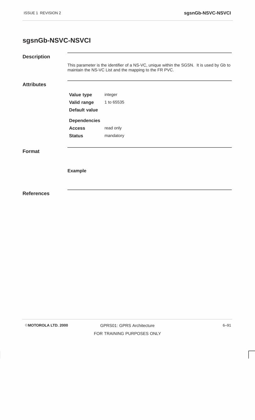
ISSUE 1 REVISION 2 sgsnGb-NSVC-NSVCI
�MOTOROLA LTD. 2000 GPRS01: GPRS Architecture
FOR TRAINING PURPOSES ONLY
6–91
sgsnGb-NSVC-NSVCI
Description
This parameter is the identifier of a NS-VC, unique within the SGSN. It is used by Gb tomaintain the NS-VC List and the mapping to the FR PVC.
Attributes
Value type integer
Valid range 1 to 65535
Default value
Dependencies
Access read only
Status mandatory
Format
Example
References

ISSUE 1 REVISION 2sgsnGb-NSVC-DLCI
�MOTOROLA LTD. 2000GPRS01: GPRS Architecture
FOR TRAINING PURPOSES ONLY
6–92
sgsnGb-NSVC-DLCI
Description
This parameter is the FR PVC Data Link Connection ID, unique per FR BearerChannel. Itis used, together with the BearerChannelId, by Gb to maintain the NS-VCI to PVCmapping.
The valid range is 16 to 991; 0 to 15 are reserved for FR and are therefore not availablefor general use.
Attributes
Value type integer
Valid range 16 to 991
Default value 16
Dependencies
Access read only
Status mandatory
Format
Example
References

ISSUE 1 REVISION 2 sgsnGb-NSVC-LinkId
�MOTOROLA LTD. 2000 GPRS01: GPRS Architecture
FOR TRAINING PURPOSES ONLY
6–93
sgsnGb-NSVC-LinkId
Description
This parameter is the identifier for the physical link (E1/T1) as defined in thesgsnGb-FR-Table .
Attributes
Value type integer
Valid range 0 to 3
Default value 0
Dependencies
Access read only
Status mandatory
Format
Example
References

ISSUE 1 REVISION 2sgsnGb-NSVC-BearerChannelId
�MOTOROLA LTD. 2000GPRS01: GPRS Architecture
FOR TRAINING PURPOSES ONLY
6–94
sgsnGb-NSVC-BearerChannelId
Description
This parameter is the FR Channel Identifier of the PVC associated with the NS-VC, asdefined in the sgsnGb-FR-Table .
Attributes
Value type integer
Valid range 0 to 30
Default value 0
Dependencies
Access read only
Status mandatory
Format
Example
References

ISSUE 1 REVISION 2 sgsnGb-NSVC-FR-PVC-CIR
�MOTOROLA LTD. 2000 GPRS01: GPRS Architecture
FOR TRAINING PURPOSES ONLY
6–95
sgsnGb-NSVC-FR-PVC-CIR
Description
This parameter is the committed information rate (bits/sec) at which the FR networktransfers information to the end system under normal conditions. The rate is averagedover time interval T, where T is calculated to be Bc/CIR.
The maximum value will be the rate of full E1 (32 x 64k)
Attributes
Value type integer
Valid range 1 to 2048000
Default value 1
Dependencies
Access read only
Status mandatory
Format
Example
References

ISSUE 1 REVISION 2sgsnGb-NSVCFRPVCBc
�MOTOROLA LTD. 2000GPRS01: GPRS Architecture
FOR TRAINING PURPOSES ONLY
6–96
sgsnGb-NSVCFRPVCBc
Description
This parameter is the committed burst size. This is the maximum amount of data (in bits)that the FR network agrees to transfer under normal conditions, during time interval T.This data may or may not be interrupted (that is, it may appear in one frame or severalframes).
Attributes
Value type integer
Valid range 1 to 2048000
Default value 1
Dependencies
Access read only
Status mandatory
Format
Example
References

ISSUE 1 REVISION 2 sgsnGb-NSVC-FR-PVC-Be
�MOTOROLA LTD. 2000 GPRS01: GPRS Architecture
FOR TRAINING PURPOSES ONLY
6–97
sgsnGb-NSVC-FR-PVC-Be
Description
This parameter is the maximum amount of uncommitted data (in bits) in excess of Bcthat the FR network will attempt to deliver, during time interval T. This data may or maynot be interrupted (that is, it may appear in one frame or several frames). Excess burstis marked discard eligible (DE) by the FRS driver.
Attributes
Value type integer
Valid range 0 to 2048000
Default value 0
Dependencies
Access read only
Status mandatory
Format
Example
References
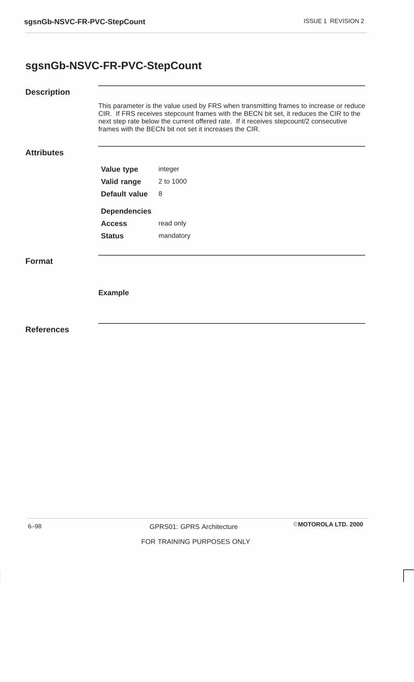
ISSUE 1 REVISION 2sgsnGb-NSVC-FR-PVC-StepCount
�MOTOROLA LTD. 2000GPRS01: GPRS Architecture
FOR TRAINING PURPOSES ONLY
6–98
sgsnGb-NSVC-FR-PVC-StepCount
Description
This parameter is the value used by FRS when transmitting frames to increase or reduceCIR. If FRS receives stepcount frames with the BECN bit set, it reduces the CIR to thenext step rate below the current offered rate. If it receives stepcount/2 consecutiveframes with the BECN bit not set it increases the CIR.
Attributes
Value type integer
Valid range 2 to 1000
Default value 8
Dependencies
Access read only
Status mandatory
Format
Example
References
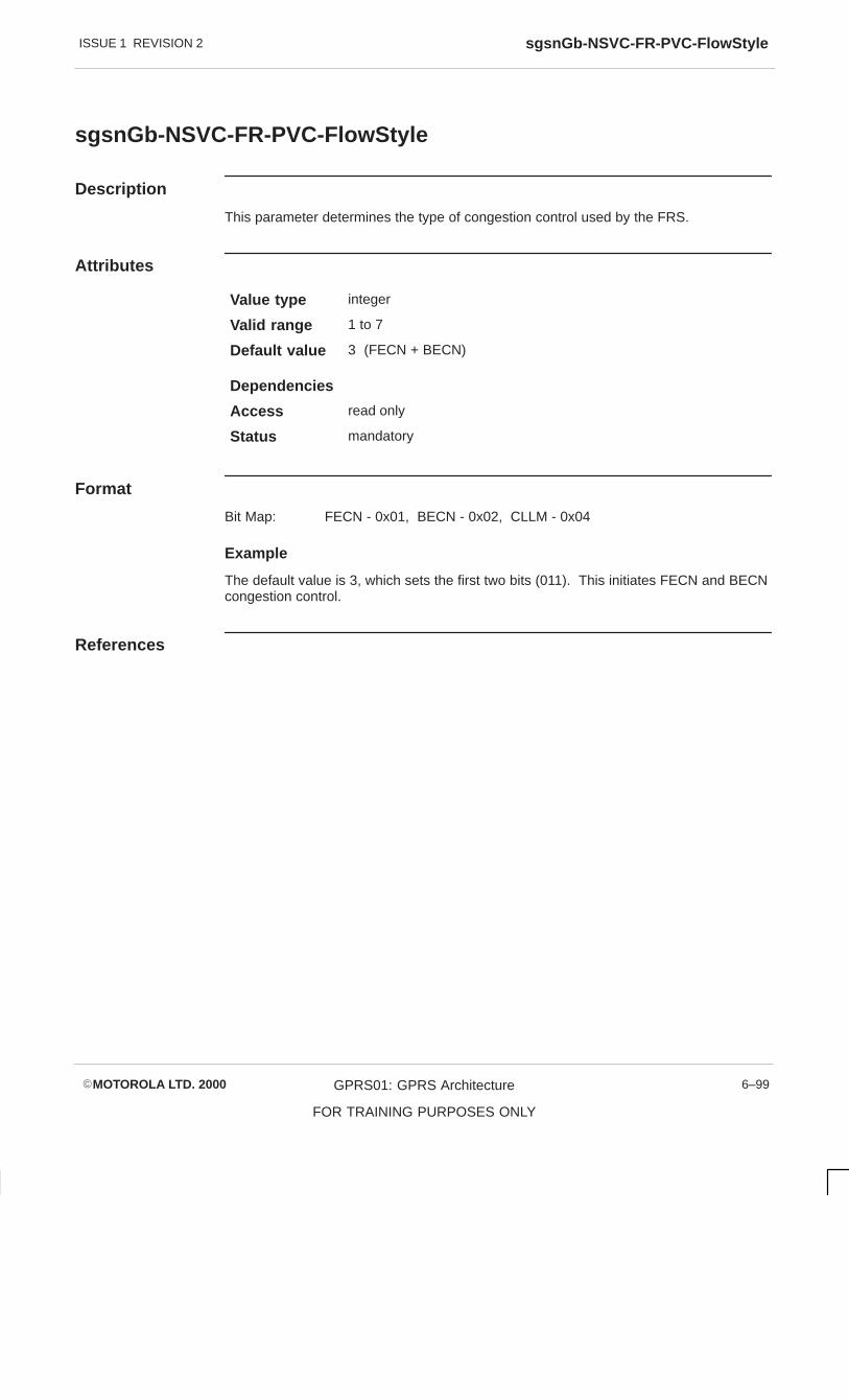
ISSUE 1 REVISION 2 sgsnGb-NSVC-FR-PVC-FlowStyle
�MOTOROLA LTD. 2000 GPRS01: GPRS Architecture
FOR TRAINING PURPOSES ONLY
6–99
sgsnGb-NSVC-FR-PVC-FlowStyle
Description
This parameter determines the type of congestion control used by the FRS.
Attributes
Value type integer
Valid range 1 to 7
Default value 3 (FECN + BECN)
Dependencies
Access read only
Status mandatory
Format
Bit Map: FECN - 0x01, BECN - 0x02, CLLM - 0x04
Example
The default value is 3, which sets the first two bits (011). This initiates FECN and BECNcongestion control.
References

ISSUE 1 REVISION 2sgsnLLC-VersionNum
�MOTOROLA LTD. 2000GPRS01: GPRS Architecture
FOR TRAINING PURPOSES ONLY
6–100
sgsnLLC-VersionNum
Description
This parameter identifies the version of GPRS LLC that is running.
Attributes
Value type integer
Valid range 0 to 15
Default value 0
Dependencies
Access read only
Status mandatory
Format
Example
References

ISSUE 1 REVISION 2 BSSGP parameter diagrams
�MOTOROLA LTD. 2000 GPRS01: GPRS Architecture
FOR TRAINING PURPOSES ONLY
6–101
BSSGP parameter diagrams
BVC block timer
The following diagram details BVC block and unblock messages. The sgsnBssgpT1parameter determines the period of the BVC block timer,T1, which controls the blockingand unblocking procedures. A block or unblock message is sent every T1 seconds untilthe appropriate acknowlegement is received.
PCU SGSN
BVC Block STARTT1
BVC Block ACK STOPT1
sgsnBssgpT1Range 1 – 30 Secs
Default 3
BVC Unblock
OR
BVC Unblock ACK
OR
Figure 6-22 BVC block timer

ISSUE 1 REVISION 2BSSGP parameter diagrams
�MOTOROLA LTD. 2000GPRS01: GPRS Architecture
FOR TRAINING PURPOSES ONLY
6–102
BVC reset timer
The following diagram details BVC reset messages. The sgsnBssgpT2 parameterdetermines the period of the BVC reset timer, T2. The timer is started when the resetmessage is sent and stopped on receipt of the reset acknowledgement.
The BVC Reset forces peer entities to a known (blocked) state. Once both entities are atthe same state the BVC unblock procedures can be carried out to bring the BVC intoservice.
PCU SGSN
BVC Reset STARTT2
BVC Reset ACK STOPT2
sgsnBssgpT2Range 1 – 1000 Secs
Default 60
Figure 6-23 BVC reset timer

ISSUE 1 REVISION 2 BSSGP parameter diagrams
�MOTOROLA LTD. 2000 GPRS01: GPRS Architecture
FOR TRAINING PURPOSES ONLY
6–103
BVC block retries
The following diagram details the BVC Block message, which is repeated if no responseis received during period T1. The sgsnBssgpBvcBlockRetries parameter is used toset the number of times that the BVC Block message is sent.
PCU SGSN
BVC Block T1
BVC Block T1
sgsnBssgpBvcBlockRetriesRange 1 – 30
Default 3
repeated for BVCBlockRetries
Figure 6-24 BVC block retries

ISSUE 1 REVISION 2BSSGP parameter diagrams
�MOTOROLA LTD. 2000GPRS01: GPRS Architecture
FOR TRAINING PURPOSES ONLY
6–104
BVC unblockretries
The following diagram details the BVC Unblock message, which is repeated if noresponse is received during period T1. The sgsnBssgpBvcUnblockRetries parameteris used to set the number of times that the BVC Unblock message is sent.
PCU SGSN
BVC Unblock T1
BVC Unblock T1
sgsnBssgpBvcUnblockRetriesRange 1 – 30
Default 3
repeated for BVCUnblockRetries
Figure 6-25 BVC unblock retries

ISSUE 1 REVISION 2 BSSGP parameter diagrams
�MOTOROLA LTD. 2000 GPRS01: GPRS Architecture
FOR TRAINING PURPOSES ONLY
6–105
BVC reset retries
The following diagram details the BVC Reset message, which is repeated if no responseis received during period T2. The sgsnBssgpBvcResetRetries parameter is used toset the number of times that the BVC Reset message is sent.
PCU SGSN
BVC Reset T2
BVC Reset T2
sgsnBssgpBvcResetRetriesRange 1 – 30
Default 3
repeated for BVCResetRetries
Figure 6-26 BVC set retries


ISSUE 1 REVISION 2sgsnGb-BVC-Table
�MOTOROLA LTD. 2000GPRS01: GPRS Architecture
FOR TRAINING PURPOSES ONLY
6–106
sgsnGb-BVC-Table
Description
This table lists the BVCI to NS-VCI mappings for this SGSN.
Row Creation: For the successful creation of a row in this table, the referredNS-VCI must have already been defined in thesgsnGb-NSVC-Table .
Row Deletion: A row may be deleted if the BVC defined by the row is not beingreferenced by any rows in sgsnGb-CellTable orsgsnSigPlaneInfoTable .
Row Update Currently, the software does not have provision to update individualentry values for a row after it has been created. Updates can onlybe achieved by deleting the existing row and then inserting a newrow containing the new values, through separate managementrequests.
Attributes
Value type
Valid range
Default value
Dependencies
Access not accessible
Status mandatory
Format
Example
References

ISSUE 1 REVISION 2 sgsnGb-BVC-TableEntry
�MOTOROLA LTD. 2000 GPRS01: GPRS Architecture
FOR TRAINING PURPOSES ONLY
6–107
sgsnGb-BVC-TableEntry
Description
This parameter defines one BVCI.
Attributes
Value type ???
Valid range ???
Default value ???
Dependencies
Access not accessible
Status mandatory
Format
sgsnGb-BVC-TableEntry ::=
SEQUENCE{
sgsnGb-BVC-RowStatus GSN-RowStatus,
sgsnGb-BVC-BVCI INTEGER,
sgsnGb-BVC-BVCI-Type INTEGER,
sgsnGb-BVC-NSVCI INTEGER,
sgsnNGb-BVC-SigBVCI INTEGER,
}
Example
References

ISSUE 1 REVISION 2sgsnGb-BVC-RowStatus
�MOTOROLA LTD. 2000GPRS01: GPRS Architecture
FOR TRAINING PURPOSES ONLY
6–108
sgsnGb-BVC-RowStatus
Description
This parameter indicates the status of a table row.
Attributes
Value type
Valid range
Default value undefined
Dependencies
Access read - write
Status mandatory
Format
Example
References

ISSUE 1 REVISION 2 sgsnGb-BVC-BVCI
�MOTOROLA LTD. 2000 GPRS01: GPRS Architecture
FOR TRAINING PURPOSES ONLY
6–109
sgsnGb-BVC-BVCI
Description
This parameter is the identifier of the BVC, unique within the SGSN. It is used by Gb tocommunicate with BSS over the end-to-end BVCs.
Attributes
Value type integer
Valid range 1 to 65535 (ffff hex)
Default value
Dependencies
Access read only
Status mandatory
Format
Example
References
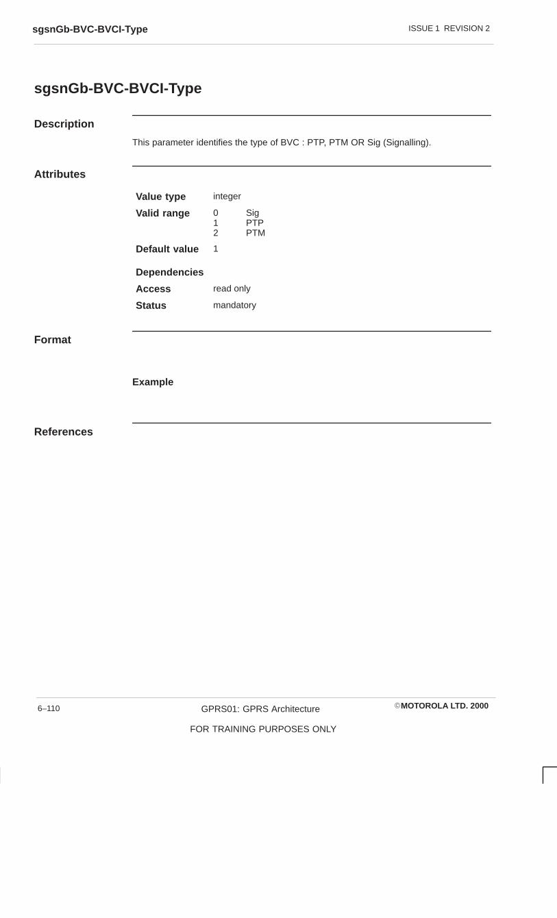
ISSUE 1 REVISION 2sgsnGb-BVC-BVCI-Type
�MOTOROLA LTD. 2000GPRS01: GPRS Architecture
FOR TRAINING PURPOSES ONLY
6–110
sgsnGb-BVC-BVCI-Type
Description
This parameter identifies the type of BVC : PTP, PTM OR Sig (Signalling).
Attributes
Value type integer
Valid range 0 Sig1 PTP2 PTM
Default value 1
Dependencies
Access read only
Status mandatory
Format
Example
References

ISSUE 1 REVISION 2 sgsnGb-BVC-NSVCI
�MOTOROLA LTD. 2000 GPRS01: GPRS Architecture
FOR TRAINING PURPOSES ONLY
6–111
sgsnGb-BVC-NSVCI
Description
This parameter identifies the NS-VC that serves this BVC. It is used by Gb to maintainthe BVCI to NS-VCI mapping. The parameter must be defined in sgsnGb-NSVC-Table .
Attributes
Value type integer
Valid range 1 to 65535 (ffff hex)
Default value 0
Dependencies
Access read only
Status mandatory
Format
Example
References

ISSUE 1 REVISION 2sgsnGb-BVC-SigBVCI
�MOTOROLA LTD. 2000GPRS01: GPRS Architecture
FOR TRAINING PURPOSES ONLY
6–112
sgsnGb-BVC-SigBVCI
Description
This parameter identifies the signalling BVC associated with the BVC/NS-VC pair (whenthe BVC is of the type PTP or PTM) being defined by the table row. It is used by Gb tocommunicate with BSS when the data BVC fails.
When the BVC in the BVC/NS-VC pair is a signalling BVC itself, this field will have avalue of 0. If the value of this field is not 0, it should already have been previouslydefined in the BVC table. It should be noted, that while 0 is not a valid BVCI value, it isallowed for this field.
Attributes
Value type integer
Valid range 0 to 65535 (ffff hex)
Default value
Dependencies sgsnGb-BVC-BVCI
Access read only
Status mandatory
Format
Example
References

ISSUE 1 REVISION 2 sgsnBSSGP-T1
�MOTOROLA LTD. 2000 GPRS01: GPRS Architecture
FOR TRAINING PURPOSES ONLY
6–113
sgsnBSSGP-T1
Description
This parameter is the timer, in seconds, that guards the blocking and unblockingprocedures.
The block or unblock is sent every sgsnBssgpT1 seconds until the peer acknowledges orthe number of retries (sgsnBssgpBvcBlockRetries orsgsnBssgpBvcUnblockRetries ) is completed.
Attributes
Value type integer
Valid range 1 to 30
Default value 3
Dependencies
Access read - write
Status mandatory
Format
Example
References

ISSUE 1 REVISION 2sgsnBSSGP–T2
�MOTOROLA LTD. 2000GPRS01: GPRS Architecture
FOR TRAINING PURPOSES ONLY
6–114
sgsnBSSGP–T2
Description
This parameter is the timer, in seconds, that guards the reset procedure.
The reset is sent every sgsnBssgpT2 seconds until the peer acknowledges or thenumber of retries (sgsnBssgpBvcResetRetries ) is completed.
Attributes
Value type integer
Valid range 1 to 1000
Default value 60
Dependencies
Access read - write
Status mandatory
Format
Example
References

ISSUE 1 REVISION 2 sgsnBSSGP–BVC-BlockRetries
�MOTOROLA LTD. 2000 GPRS01: GPRS Architecture
FOR TRAINING PURPOSES ONLY
6–115
sgsnBSSGP–BVC-BlockRetries
Description
This parameter indicates the number of attempts to retry a BVC-BLOCK.
Attributes
Value type integer
Valid range 1 to 30
Default value 3
Dependencies
Access read - write
Status mandatory
Format
Example
References

ISSUE 1 REVISION 2sgsnBSSGP-BVC-UnblockRetries
�MOTOROLA LTD. 2000GPRS01: GPRS Architecture
FOR TRAINING PURPOSES ONLY
6–116
sgsnBSSGP-BVC-UnblockRetries
Description
This parameter indicates the number of attempts to retry a BVC-UNBLOCK.
Attributes
Value type integer
Valid range 1 to 30
Default value 3
Dependencies
Access read - write
Status mandatory
Format
Example
References

ISSUE 1 REVISION 2 sgsnBSSGP-BVC-ResetRetries
�MOTOROLA LTD. 2000 GPRS01: GPRS Architecture
FOR TRAINING PURPOSES ONLY
6–117
sgsnBSSGP-BVC-ResetRetries
Description
This parameter indicates the number of attempts to retry a BVC-RESET.
Dependencies
Access read - write
Status mandatory
Format
Example
Attributes
Value type integer
Valid range 1 to 30
Default value 3
References

ISSUE 1 REVISION 2sgsnGb-Cell-Table
�MOTOROLA LTD. 2000GPRS01: GPRS Architecture
FOR TRAINING PURPOSES ONLY
6–118
sgsnGb-Cell-Table
Description
This table provides the Cell to BVCI mappings that are defined for this SGSN.
Row Creation: For the successful creation of a row in this table, the referred BVCImust have already been defined in the sgsnGb-BVC-Table .
Row Deletion: There is no restriction on row deletion.
Row Update Currently, the software does not have provision to update individualentry values for a row after it has been created. Updates can onlybe achieved by deleting the existing row and then inserting a newrow containing the new values, through separate managementrequests.
Attributes
Value type
Valid range
Default value
Dependencies
Access not accessible
Status mandatory
Format
Example
References

ISSUE 1 REVISION 2 sgsnGb-Cell-BVC-TableEntry
�MOTOROLA LTD. 2000 GPRS01: GPRS Architecture
FOR TRAINING PURPOSES ONLY
6–119
sgsnGb-Cell-BVC-TableEntry
Description
Each entry defines one <CGI, PTP–BVCI> pair.
Attributes
Value type
Valid range
Default value
Dependencies
Access not accessible
Status mandatory
Format
sgsnRaiNseiEntry ::=
SEQUENCE{
sgsnGb-Cell-BVCRowStatus GSN-RowStatus,
sgsnGb-Cell-BVCMCC Display String,
sgsnGb-Cell-BVCMNC Display String,
sgsnGb-Cell-BVCLAC INTEGER,
sgsnGb-Cell-BVC-CI INTEGER,
sgsnGb-Cell-BVC-PTP-BVCI INTEGER
}
Example
References

ISSUE 1 REVISION 2sgsnGb-Cell-BVCRowStatus
�MOTOROLA LTD. 2000GPRS01: GPRS Architecture
FOR TRAINING PURPOSES ONLY
6–120
sgsnGb-Cell-BVCRowStatus
Description
This parameter indicates the status of a table row.
Attributes
Value type
Valid range
Default value undefined
Dependencies
Access read - write
Status mandatory
Format
Example
References

ISSUE 1 REVISION 2 sgsnGb-Cell-BVC-MCC
�MOTOROLA LTD. 2000 GPRS01: GPRS Architecture
FOR TRAINING PURPOSES ONLY
6–121
sgsnGb-Cell-BVC-MCC
Description
This parameter identifies the Mobile Country Code.
Attributes
Value type display string
Valid range
Default value
Dependencies
Access read only
Status mandatory
Format
3 decimal digits in ASCII format, according to CCITT Rec E.212.
Example
References
CCITT Rec E.212

ISSUE 1 REVISION 2sgsnGb-Cell-BVCMNC
�MOTOROLA LTD. 2000GPRS01: GPRS Architecture
FOR TRAINING PURPOSES ONLY
6–122
sgsnGb-Cell-BVCMNC
Description
This parameter identifies the Mobile Network Code.
Attributes
Value type display string
Valid range
Default value
Dependencies
Access read only
Status mandatory
Format
2 decimal digits in ASCII format, according to CCITT Rec E.212.
Example
References
CCITT Rec E.212

ISSUE 1 REVISION 2 sgsnGb-Cell-BVCLAC
�MOTOROLA LTD. 2000 GPRS01: GPRS Architecture
FOR TRAINING PURPOSES ONLY
6–123
sgsnGb-Cell-BVCLAC
Description
This parameter identifies the Location Area Code.
Attributes
Value type integer
Valid range 0 to 65535
Default value
Dependencies
Access read only
Status mandatory
Format
2 bytes integer, according to TS GSM 04.08
Example
References
TS GSM 04.08

ISSUE 1 REVISION 2sgsnGb-Cell-BVC-CI
�MOTOROLA LTD. 2000GPRS01: GPRS Architecture
FOR TRAINING PURPOSES ONLY
6–124
sgsnGb-Cell-BVC-CI
Description
This parameter identifies the cell identity.
Attributes
Value type integer
Valid range 0 to 65535
Default value
Dependencies
Access read only
Status mandatory
Format
2 bytes integer, according to TS GSM 04.08
Example
References
TS GSM 04.08
ISSUE 1 REVISION 2 sgsnGb-Cell-BVC-PTP-BVCI
�MOTOROLA LTD. 2000 GPRS01: GPRS Architecture
FOR TRAINING PURPOSES ONLY
6–125
sgsnGb-Cell-BVC-PTP-BVCI
Description
This parameter is the identifier of the PTP BVCI serving this cell. It is used by Gb tomaintain the CGI to PTP BVCI mappings. It must be defined in sgsnGb-BVC-Table .
Attributes
Value type integer
Valid range 0 to 65535
Default value
Dependencies sgsnGb-BVC-BVCI
Access read only
Status mandatory
Format
Example
References
TS GSM 04.08

ISSUE 1 REVISION 2sgsnSigPlaneInfoTable
�MOTOROLA LTD. 2000GPRS01: GPRS Architecture
FOR TRAINING PURPOSES ONLY
6–126
sgsnSigPlaneInfoTable
Description
This table provides Signalling Plane Control Information for this SGSN. It is used by theSGSN to obtain the following mappings: CGI > RAI, CGI > SIG BVCI and RAI > SIGBVCI (PCU).
Row Creation: For succesful row creation, the referred BVCI must have alreadybeen defined in the sgsnGb-BVC-Table .
Row Deletion: No restrictions.
Row Update The software does not currently have the provision to updateindividual entry values after a row has been created. Updates canonly be achieved by deleting the existing row and then inserting anew row with the new values.
Attributes
Value type
Valid range
Default value
Dependencies
Access not accessible
Status mandatory
Format
Example
References

ISSUE 1 REVISION 2 sgsnSigPlaneInfoTableEntry
�MOTOROLA LTD. 2000 GPRS01: GPRS Architecture
FOR TRAINING PURPOSES ONLY
6–127
sgsnSigPlaneInfoTableEntry
Description
This parameter defines the entry structure for the sgsnSigPlaneInfoTable .
Attributes
Value type
Valid range
Default value
Dependencies
Access not accessible
Status mandatory
Format
sgsnSigPlaneInfoTableEntry ::=
SEQUENCE{
sgsnSigPlaneInfotRowStatus GSN-RowStatus,
sgsnSigPlaneInfo-MCC DISPLAYSTRING,
sgsnSigPlaneInfo-MNC DISPLAYSTRING,
sgsnSigPlaneInfo-LAC INTEGER,
sgsnSigPlaneInfo-CI INTEGER,
sgsnSigPlaneInfo-RAC
sgsnSigPlaneInfoSIG-BVCI
INTEGER,
INTEGER
}
Example
References

ISSUE 1 REVISION 2sgsnSigPlaneInfoRowStatus
�MOTOROLA LTD. 2000GPRS01: GPRS Architecture
FOR TRAINING PURPOSES ONLY
6–128
sgsnSigPlaneInfoRowStatus
Description
This parameter indicates the status of a table row.
Attributes
Value type
Valid range
Default value undefined
Dependencies
Access read - write
Status mandatory
Format
Example
References

ISSUE 1 REVISION 2 sgsnSigPlaneInfo-MCC
�MOTOROLA LTD. 2000 GPRS01: GPRS Architecture
FOR TRAINING PURPOSES ONLY
6–129
sgsnSigPlaneInfo-MCC
Description
This parameter identifies the Mobile Country Code.
Attributes
Value type integer
Valid range
Default value
Dependencies
Access read only
Status mandatory
Format
2 digits decimal in ASCII format, according to CCITT Rec E.212
Example
References
CCITT Rec E.212

ISSUE 1 REVISION 2sgsnSigPlaneInfo-MNC
�MOTOROLA LTD. 2000GPRS01: GPRS Architecture
FOR TRAINING PURPOSES ONLY
6–130
sgsnSigPlaneInfo-MNC
Description
This parameter identifies the Mobile Network Code.
Attributes
Value type
Valid range
Default value
Dependencies
Access read only
Status mandatory
Format
2 digits decimal in ASCII format, according to CCITT Rec E.212
Example
References
CCITT Rec E.212

ISSUE 1 REVISION 2 sgsnSigPlaneInfo-LAC
�MOTOROLA LTD. 2000 GPRS01: GPRS Architecture
FOR TRAINING PURPOSES ONLY
6–131
sgsnSigPlaneInfo-LAC
Description
This parameter identifies the Location Area Code.
Attributes
Value type integer
Valid range 0 to 65535
Default value
Dependencies
Access read only
Status mandatory
Format
2 digits decimal in ASCII format, according to TS GSM 04.08.
Example
References
TS GSM 04.08

ISSUE 1 REVISION 2sgsnSigPlaneInfo-CI
�MOTOROLA LTD. 2000GPRS01: GPRS Architecture
FOR TRAINING PURPOSES ONLY
6–132
sgsnSigPlaneInfo-CI
Description
This parameter identifies the Cell Identity.
Attributes
Value type integer
Valid range 0 to 65535
Default value
Dependencies
Access read only
Status mandatory
Format
2 bytes integer, according to TS GSM 04.08
Example
References
TS GSM 04.08

ISSUE 1 REVISION 2 sgsnSigPlaneInfo-RAC
�MOTOROLA LTD. 2000 GPRS01: GPRS Architecture
FOR TRAINING PURPOSES ONLY
6–133
sgsnSigPlaneInfo-RAC
Description
This parameter identifies the Routing Area Code, part of a Global identifier of a RoutingArea. RAI is defined as MCC + MNV + LAC + RAC, since the MCC, MNC and LAC arepreviously defined, the only remaining requirement is RAC, to form the RAI.
Attributes
Value type integer
Valid range 0 to 255
Default value
Dependencies
Access read only
Status mandatory
Format
1 bytes integer
Example
References

ISSUE 1 REVISION 2sgsnSigPlaneInfoSIG-BVCI
�MOTOROLA LTD. 2000GPRS01: GPRS Architecture
FOR TRAINING PURPOSES ONLY
6–134
sgsnSigPlaneInfoSIG-BVCI
Description
This parameter identifies the Signalling BVCI of a PCU and must be defined insgsnGb–BVC-Table .
Attributes
Value type integer
Valid range 1 to 65535
Default value
Dependencies
Access read only
Status mandatory
Format
1 bytes integer
Example
References

�MOTOROLA LTD. 2000 GPRS01: GPRS Architecture
FOR TRAINING PURPOSES ONLY
i
Chapter 7
SGSN Statistics Attributes

ISSUE 1 REVISION 2
�MOTOROLA LTD. 2000GPRS01: GPRS Architecture
FOR TRAINING PURPOSES ONLY
ii

ISSUE 1 REVISION 2 Introduction to SGSN statistics
�MOTOROLA LTD. 2000 GPRS01: GPRS Architecture
FOR TRAINING PURPOSES ONLY
7–1
Introduction to SGSN statistics
Purpose of thischapter
This chapter describes statistical measurements generated by the SGSN element of theGSN, in response to monitored network and system events.
How this chapteris structured
This chapters contains SGSN statistics information, using the following structure topresent that information:
� An introduction to the chapter and the chapter structure.
� Details of the MIB structure identifying the available SGSN objects.
� Attributes tables detailing the statistics attributes available for each SGSN object.
� Ladder diagrams describing when the statistics are generated (pegged).
� Traffic direction diagrams indicating the statistics applicable to uplink anddownlink traffic.
� Data sheets containing the attribute information of the individual statistics identifiedin the attributes tables.
This information may be structured differently for training purposes
NOTE
SGSN OIDstructure
The following illustration identifies the SGSN OID structure, which forms part of theoverall OID structure.

ISSUE 1 REVISION 2Introduction to SGSN statistics
�MOTOROLA LTD. 2000GPRS01: GPRS Architecture
FOR TRAINING PURPOSES ONLY
7–2
(1) System
(2) OAMP
(3) HA
(4) OP
(5) Gb
(6) Gn
(7) Sig
(8) Meter
(9) Perf
(10) SW
mot-gprs-sgsm
(1) diag
(2) action
(1) bssgp
(2) NS
(1) SM
(2) SNDCP
(3) LLC
(1) GTP
(2) GMM
Figure 7-1 SGSN OID structure
Attributes Tables
Details of the attributes available for each performance management object can be foundin the following tables:

ISSUE 1 REVISION 2 Introduction to SGSN statistics
�MOTOROLA LTD. 2000 GPRS01: GPRS Architecture
FOR TRAINING PURPOSES ONLY
7–3
Sig GTP Table 7-1
GTP_Gn Table 7-2
SNDCP Table 7-3
LLC Table 7-4
BSSGP Table 7-5
NS Table 7-6
FR NO TAG
L3MM Table 7-7
Misc Table 7-8
Ladder diagrams
The following performance management ladder diagrams are available:
Figure 7-2 Signalling GTP Session Activation statistics
Figure 7-3 Signalling GTP Protocol Error statistics
Figure 7-9 L3MM Attach statistics
Figure 7-10 L3MM Detach statistics
Figure 7-11 L3MM Session Activation statistics
Figure 7-12 L3MM Deactivation statistics
Figure 7-13 L3MM RA Update statistics
Traffic directiondiagrams
The following performance management traffic direction diagrams are available:
Figure 2-4 GTP_Gn protocol layer
Figure 2-5 SNDCP protocol layer
Figure 2-6 LLC protocol layer
Figure 2-7 BSSGP protocol layer
Figure 2-8 NS protocol layer


ISSUE 1 REVISION 2Signalling GTP statistics tables and diagrams
�MOTOROLA LTD. 2000GPRS01: GPRS Architecture
FOR TRAINING PURPOSES ONLY
7–4
Signalling GTP statistics tables and diagrams
Introduction tosignalling GTPtables anddiagrams
The information in this section is an aid to understanding the statistics function of aparticular SGSN object.
Table 7-1 identifies the statistics attributes available for the signalling GTP interface.
The following diagrams are used to explain when the statistics are pegged:
Figure 7-2 Signalling GTP Session Activation.
Figure 7-3 Signalling GTP Protocol Error.
Signallinginterface overGTP statistics
The following table details the statistics attributes available for sgsn-perf-gtp-sig :
Table 7-1 SGSN signalling GTP statistics attributes
OIDnumber
attribute
1 sgsnNumSuccessSessionActivationRcvd
2 sgsnNumUnsuccessSessionActivationRcvd
3 sgsnNumSessionActivationSent
4 sgsnNumProtocolErrorTooShort
5 sgsnNumProtocolErrorWrongHeader
6 sgsnNumProtocolErrorUnexpectedMsg

ISSUE 1 REVISION 2 Signalling GTP statistics tables and diagrams
�MOTOROLA LTD. 2000 GPRS01: GPRS Architecture
FOR TRAINING PURPOSES ONLY
7–5
Signalling GTPSessionActivationstatistics
The following is a ladder diagram detailing a Signalling GTP Session Activation Sent froma SGSN to a GGSN, and the expected responses. It also indicates the statistics peggedfor the Request and the responses.
sgsnNumSessionActivationSent
sgsnNumSuccessSessionActivationRcvd
sgsnNumUnsuccessSessionActivationRcvd
SGSN GGSN
PDP CONTEXT REQUEST
PDP CONTEXT ACCEPT
OR
PDP CONTEXT REJECT
Figure 7-2 Signalling GTP Session Activation

ISSUE 1 REVISION 2Signalling GTP statistics tables and diagrams
�MOTOROLA LTD. 2000GPRS01: GPRS Architecture
FOR TRAINING PURPOSES ONLY
7–6
Signalling GTPProtocol Errorstatistics
The following is a ladder diagram detailing a Signalling GTP Protocol Error statisticspegged as a result of incorrect signalling information received from the GGSN.
sgsnNumProtocolErrorTooShort
sgsnNumProtocolErrorWrongHeader
sgsnNumProtocolErrorUnexpectedMsg
SGSN GGSN
BAD SIGNALLING PDU
BAD SIGNALLING PDU
SIGNALLING PDU
Figure 7-3 Signalling GTP Protocol Error

ISSUE 1 REVISION 2 GTP_Gn statistics tables and diagrams
�MOTOROLA LTD. 2000 GPRS01: GPRS Architecture
FOR TRAINING PURPOSES ONLY
7–7
GTP_Gn statistics tables and diagrams
Introduction toGTP_Gn tablesand diagrams
The information in this section is an aid to understanding the statistics function of aparticular SGSN object.
Table 7-2 identifies the statistics attributes available for the GTP_Gn interface.
The following diagram is used to explain when the statistics are pegged:
Figure 7-4 GTP protocol layer.
Gn interfacestatistics
The following table details the statistics attributes available for sgsn-perf-gtp-gn :
Table 7-2 SGSN GTP_Gn interface statistics attributes
OIDnumber
attribute
1 sgsnNumCurrentGgsnConnections
2 sgsnNumGtpDataPacketSentToGGSN
3 sgsnNumGtpDatabytesSentToGGSN
4 sgsnNumGtpDataPacketsRcvdFromGGSN
5 sgsnNumGtpDataBytesRcvdFromGGSN
6 sgsnNumGtpDownLinkDataPacketsSent
7 sgsnNumGtpDownLinkDataBytesSent
8 sgsnNumGtpUpLinkDataPacketsRcvd
9 sgsnNumGtpUpLinkDataBytesRcvd
10 sgsnNumGtpUpLinkDataPacketsDropped
11 sgsnNumGtpDownLinkDataPacketsDropped

ISSUE 1 REVISION 2GTP_Gn statistics tables and diagrams
�MOTOROLA LTD. 2000GPRS01: GPRS Architecture
FOR TRAINING PURPOSES ONLY
7–8
GTP_Gn protocollayer
The following diagram details the traffic direction and statistics associated with the SGSNGTP_Gn protocol layer
SGSN
UplinkDownlinksgsnNumGtpDownLinkDataPacketsSentsgsnNumGtpDownLinkDataBytesSentsgsnNumGtpDataPacketsRcvdFromGGSNsgsnNumGtpDataBytesRcvdFromGGSNsgsnNumGtpDownLinkDataPacketsDropped
MS BSS GGSN
RLC
MAC
GSM RF
SNDCP
LLC
BSSGP
L1
L2
IP
TCP/UDP
GTP
IP
NetworkService
L1
L2
IP
TCP/UDP
GTP
NetworkService
L1 Bis
BSSGP
LLC
SNDCP
GSM RF
MAC
RLC
IP
Uplink Sent
Uplink Rcvd
Downlink Sent
Downlink Rcvd
L1 Bis
sgsnNumGtpUpLinkDataPacketsRcvdsgsnNumGtpUpLinkDataBytesRcvdsgsnNumGtpDataPacketsSentToGGSNsgsnNumGtpDataBytesSentToGGSNsgsnNumGtpUpLinkDataPacketsDropped
Figure 7-4 GTP protocol layer

ISSUE 1 REVISION 2 SNDCP statistics tables and diagrams
�MOTOROLA LTD. 2000 GPRS01: GPRS Architecture
FOR TRAINING PURPOSES ONLY
7–9
SNDCP statistics tables and diagrams
Introduction toSNDCP tablesand diagrams
The information in this section is an aid to understanding the statistics function of aparticular SGSN object.
Table 7-3 identifies the statistics attributes available for the SNDCP protocol layer.
The following diagram is used to explain when the statistics are pegged:
Figure 7-5 SNDCP protocol layer.
SNDCP statistics
The following table details the statistics attributes available for sgsn-perf-sndcp :
Table 7-3 SGSN SNDCP statistics attributes
OIDnumber
attribute
1 sgsnNumSndcpUpLinkDataPacketsSent
2 sgsnNumSndcpUpLinkDataBytesSent
3 sgsnNumSndcpDownLinkDataPacketsRcvd
4 sgsnNumsndcpDownLinkDataBytesRcvd
5 sgsnNumSndcpDownLinkDataPacketsSent
6 sgsnNumSndcpDownLinkDataBytesSent
7 sgsnNumSndcpUpLinkDataPacketsRcvd
8 sgsnNumSndcpUpLinkDataBytesRcvd
9 sgsnNumSndcpUpLinkDataPacketsDropped
10 sgsnNumSndcpDownLinkDataPacketsDropped

ISSUE 1 REVISION 2SNDCP statistics tables and diagrams
�MOTOROLA LTD. 2000GPRS01: GPRS Architecture
FOR TRAINING PURPOSES ONLY
7–10
SNDCP protocollayer
The following diagram details the traffic direction and statistics associated with the SGSNSNDCP protocol layer
SGSN
UplinkDownlinksgsnNumSndcpDownLinkDataPacketsSentsgsnNumSndcpDownLinkDataBytesSentsgsnNumSndcpDownLinkDataPacketsRcvdsgsnNumSndcpDownLinkDataBytesRcvdsgsnNumSndcpDownLinkDataPacketsDropped
MS BSS GGSN
RLC
MAC
GSM RF
SNDCP
LLC
BSSGP
L1
L2
IP
TCP/UDP
GTP
IP
NetworkService
L1
L2
IP
TCP/UDP
GTP
L1 Bis
BSSGP
LLC
SNDCP
GSM RF
MAC
RLC
IP
Uplink Sent
Uplink Rcvd
Downlink Sent
Downlink Rcvd
L1 Bis
sgsnNumSndcpUpLinkDataPacketsRcvdsgsnNumSndcpUpLinkDataBytesRcvdsgsnNumSndcpUpLinkDataPacketsSentsgsnNumSndcpUpLinkDataBytesSentsgsnNumSndcpUpLinkDataPacketsDropped
NetworkService
Figure 7-5 SNDCP protocol layer

ISSUE 1 REVISION 2 LLC statistics tables and diagrams
�MOTOROLA LTD. 2000 GPRS01: GPRS Architecture
FOR TRAINING PURPOSES ONLY
7–11
LLC statistics tables and diagrams
Introduction toLLC tables anddiagrams
The information in this section is an aid to understanding the statistics function of aparticular SGSN object.
Table 7-4 identifies the statistics attributes available for the LLC protocol layer.
The following diagram is used to explain when the statistics are pegged:
Figure 7-6 LLC protocol layer.
LLC statistics
The following table details the statistics attributes available for sgsn-perf-llc :
Table 7-4 SGSN LLC statistics attributes
OIDnumber
attribute
1 sgsnNumLlcDownLinkDataPacketsSent
2 sgsnNumLlcDownLinkDataBytesSent
3 sgsnNumLlcUpLinkDataPacketsRcvd
4 sgsnNumLlcUpLinkDataBytesRcvd
5 sgsnNumLlcDownLinkSignalPacketsSent
6 sgsnNumLlcDownLinkSignalBytesSent
7 sgsnNumLlcUpLinkSignalPacketsRcvd
8 sgsnNumLlcUpLinkSignalBytesRcvd
9 sgsnNumLlcUpLinkDataPacketsSent
10 sgsnNumLlcUpLinkDataBytesSent
11 sgsnNumLlcDownLinkDataPacketsRcvd
12 sgsnNumLlcDownLinkDataBytesRcvd
13 sgsnNumLlcUpLinkSignalPacketsSent
14 sgsnNumLlcUpLinkSignalBytesSent
15 sgsnNumLlcDownLinkSignalPacketsRcvd
16 sgsnNumLlcDownLinkSignalBytesRcvd
17 sgsnNumLlcUpLinkDataPacketsDropped
18 sgsnNumLlcDownLinkDataPacketsDropped
19 sgsnNumLlcUpLinkSignalPacketsDropped
20 sgsnNumLlcDownLinkSignalPacketsDropped
21 sgsnNumLlcPacketsResent

ISSUE 1 REVISION 2LLC statistics tables and diagrams
�MOTOROLA LTD. 2000GPRS01: GPRS Architecture
FOR TRAINING PURPOSES ONLY
7–12
LLC protocollayer
The following diagram details the traffic direction and statistics associated with the SGSNLLC protocol layer
L1 Bis
SGSN
UplinkDownlinksgsnNumLlcDownLinkDataPacketsSentsgsnNumLlcDownLinkDataBytesSent
sgsnNumLlcDownLinkDataPacketsRcvd
sgsnNumLlcDownLinkDataBytesRcvd
sgsnNumLlcDownLinkDataPacketsDropped
MS BSS GGSN
RLC
MAC
GSM RF
SNDCP
LLC
BSSGP
L1
L2
IP
TCP/UDP
GTP
IP
NetworkService
L1
L2
IP
TCP/UDP
GTP
NetworkService
L1 Bis
BSSGP
LLC
SNDCP
GSM RF
MAC
RLC
IP
Uplink Sent
Uplink Rcvd
Downlink Sent
Downlink Rcvd
sgsnNumLlcUpLinkDataPacketsRcvdsgsnNumLlcUpLinkDataBytesRcvd
sgsnNumLlcUpLinkDataPacketsSentsgsnNumLlcUpLinkDataBytesSent
sgsnNumLlcUpLinkDataPacketsDropped
sgsnNumLlcUpLinkSignalPacketsRcvdsgsnNumLlcUpLinkSignalBytesRcvd
sgsnNumLlcUpLinkSignalPacketsSentsgsnNumLlcUpLinkSignalBytesSent
sgsnNumLlcUpLinkSignalPacketsDropped
sgsnNumLlcDownLinkSignalPacketsSent
sgsnNumLlcDownLinkSignalBytesSent
sgsnNumLlcDownLinkSignalPacketsRcvdsgsnNumLlcDownLinkSignalBytesRcvd
sgsnNumLlcDownLinkSignalPacketsDropped
Figure 7-6 LLC protocol layer

ISSUE 1 REVISION 2 BSSGP statistics tables and diagrams
�MOTOROLA LTD. 2000 GPRS01: GPRS Architecture
FOR TRAINING PURPOSES ONLY
7–13
BSSGP statistics tables and diagrams
Introduction toBSSGP tablesand diagrams
The information in this section is an aid to understanding the statistics function of aparticular SGSN object.
Table 7-5 identifies the statistics attributes available for the BSSGP protocol layer.
The following diagram is used to explain when the statistics are pegged:
Figure 7-7 BSSGP protocol layer.
BSSGP statistics
The following table details the statistics attributes available for sgsn-perf-bssgp :
Table 7-5 SGSN BSSGP statistics attributes
OIDnumber
attribute
1 sgsnNumBssgpDownLinkDataPacketsSent
2 sgsnNumBssgDownLinkdataBytesSent
3 sgsnNumBssgpUpLinkDataPacketsRcvd
4 sgsnNumBssgpUpLinkDataBytesRcvd
5 sgsnNumBssgpUpLinkDataPacketsSent
6 sgsnNumBssgpUpLinkDataBytesSent
7 sgsnNumBssgpDownLinkDataPacketsRcvd
8 sgsnNumBssgpDownLinkDataBytesRcvd
9 sgsnNumBssgpUpLinkDataPacketsDropped
10 sgsnNumBssgpDownLinkDataPacketsDropped

ISSUE 1 REVISION 2BSSGP statistics tables and diagrams
�MOTOROLA LTD. 2000GPRS01: GPRS Architecture
FOR TRAINING PURPOSES ONLY
7–14
BSSGP protocollayer
The following diagam details the traffic direction and statistics associated with the SGSNBSSGP protocol layer
SGSN
UplinksgsnNumBssgpUpLinkDataPacketsRcvdsgsnNumBssgpUpLinkDataBytesRcvdsgsnNumBssgpUpLinkDataPacketsSentsgsnNumBssgpUpLinkDataBytesSentsgsnNumBssgpUpLinkDataPacketsDropped
DownlinksgsnNumBssgpDownLinkDataPacketsSentsgsnNumBssgpDownLinkDataBytesSentsgsnNumBssgpDownLinkDataPacketsRcvdsgsnNumBssgpDownLinkDataBytesRcvdsgsnNumBssgpDownLinkDataPacketsDropped
MS BSS GGSN
RLC
MAC
GSM RF
SNDCP
LLC
BSSGP
L1
L2
IP
TCP/UDP
GTP
IP
NetworkService
L1
L2
IP
TCP/UDP
GTP
L1 Bis
NetworkService
L1 Bis
BSSGP
LLC
SNDCP
GSM RF
MAC
RLC
IP
Uplink Sent
Uplink RcvdDownlink Sent
Downlink Rcvd
Figure 7-7 BSSGP protocol layer

ISSUE 1 REVISION 2 NS statistics tables and diagrams
�MOTOROLA LTD. 2000 GPRS01: GPRS Architecture
FOR TRAINING PURPOSES ONLY
7–15
NS statistics tables and diagrams
Introduction toNS tables anddiagrams
The information in this section is an aid to understanding the statistics function of aparticular SGSN object.
Table 7-6 identifies the statistics attributes available for the NS protocol layer.
The following diagram is used to explain when the statistics are pegged:
Figure 7-8 NS protocol layer.
NS statistics
The following table details the statistics attributes available for sgsn-perf-ns :
Table 7-6 SGSN NS statistics attributes
OIDnumber
attribute
1 sgsnNumNsDownLinkDataPacketsRcvd
2 sgsnNumNsDownLinkDataBytesRcvd
3 sgsnNumNsUpLinkDataPacketsSent
4 sgsnNumNsUpLinkDataBytesSent
5 sgsnNumNsUpLinkDataPacketsRcvd
6 sgsnNumNsUpLinkDataBytesRcvd
7 sgsnNumNsDownLinkDataPacketsSent
8 sgsnNumNsDownLinkDataBytesSent
9 sgsnNumNsUpLinkDataPacketsDropped
10 sgsnNumNsDownLinkDataPacketsDropped

ISSUE 1 REVISION 2NS statistics tables and diagrams
�MOTOROLA LTD. 2000GPRS01: GPRS Architecture
FOR TRAINING PURPOSES ONLY
7–16
NS protocol layer
The following diagram details the traffic direction and statistics associated with the SGSNNS protocol layer
SGSN
UplinksgsnNumNsUpLinkDataPacketsRcvdsgsnNumNsUpLinkDataBytesRcvdsgsnNumNsUpLinkDataPacketsSentsgsnNumNsUpLinkDataBytesSentsgsnNumNsUpLinkDataPacketsDropped
DownlinksgsnNumNsDownLinkDataPacketsSentsgsnNumNsDownLinkDataBytesSentsgsnNumNsDownLinkDataPacketsRcvdsgsnNumNsDownLinkDataBytesRcvdsgsnNumNsDownLinkDataPacketsDropped
MS BSS GGSN
RLC
MAC
GSM RF
SNDCP
LLC
BSSGP
L1
L2
IP
TCP/UDP
GTP
IP
NetworkService
L1
L2
IP
TCP/UDP
GTP
NetworkService
L1 Bis
BSSGP
LLC
SNDCP
GSM RF
MAC
RLC
IP
Uplink Sent
Uplink Rcvd
Downlink Sent
Downlink Rcvd
L1 Bis
Figure 7-8 NS protocol layer

ISSUE 1 REVISION 2 L3MM statistics tables and diagrams
�MOTOROLA LTD. 2000 GPRS01: GPRS Architecture
FOR TRAINING PURPOSES ONLY
7–17
L3MM statistics tables and diagrams
Introduction toL3MM tables anddiagrams
The information in this section is an aid to understanding the statistics function of aparticular SGSN object.
Table 7-7 identifies the statistics attributes available for the L3MM interface.
The following diagrams are used to explain when the statistics are pegged:
Figure 7-9 L3MM Attach.
Figure 7-10 L3MM Detach.
Figure 7-11 L3MM Session Activation.
Figure 7-12 L3MM Session Deactivation.
Figure 7-13 L3MM RA Update.
L3MM statistics
The following table details the statistics attributes available for sgsn-perf-l3mm :
Table 7-7 SGSN L3MM statistics attributes
OIDnumber
attribute
1 sgsnNumL3mmAttachReqRcvd
2 sgsnNumL3mmAttachAcceptSent
3 sgsnNumL3mmAttachRejectSent
4 sgsnNumL3mmDetachReqRcvd
5 sgsnNumL3mmDetachAcceptSent
6 sgsnNumL3mmSessionActivateReqRcvd
7 sgsnNumL3mmSessionActivateAcceptSent
8 sgsnNumL3mmSessionActivateRejectSent
9 sgsnNumL3SessionDeactivateReqRcvd
10 sgsnNumL3mmSessionDeactivateAcceptSent
11 sgsnNumL3mmRaUpdateReqRcvd
12 sgsnNumL3mmRaUpdateAcceptSent
13 sgsnNumL3mmRaUpdateRejectSent
14 sgsnNumL3mmMsPagingReqSent
15 sgsnNumL3mmSuccessfulPages

ISSUE 1 REVISION 2L3MM statistics tables and diagrams
�MOTOROLA LTD. 2000GPRS01: GPRS Architecture
FOR TRAINING PURPOSES ONLY
7–18
L3MM Attachstatistics
The following is a ladder diagram detailing an L3MM Attach Request from an MS to theSGSN, and the expected responses. It also indicates the statistics pegged for theRequest and the responses.
MS SGSN
ATTACH REQUEST
ATTACH ACCEPT
OR
ATTACH REJECT
sgsnNumL3mmAttachReqRcvd
sgsnNumL3mmAttachAcceptSent
sgsnNumL3mmAttachRejectSent
Figure 7-9 L3MM Attach

ISSUE 1 REVISION 2 L3MM statistics tables and diagrams
�MOTOROLA LTD. 2000 GPRS01: GPRS Architecture
FOR TRAINING PURPOSES ONLY
7–19
L3MM Detachstatistics
The following is a ladder diagram detailing an L3MM Detach Request from an MS to theSGSN, and the expected response. It also indicates the statistics pegged for theRequest and the response.
MS SGSN
DETACH REQUEST
DETACH ACCEPT
sgsnNumL3mmDetachReqRcvd
sgsnNumL3mmDetachAcceptSent
Figure 7-10 L3MM Detach

ISSUE 1 REVISION 2L3MM statistics tables and diagrams
�MOTOROLA LTD. 2000GPRS01: GPRS Architecture
FOR TRAINING PURPOSES ONLY
7–20
L3MM SessionActivationstatistics
The following is a ladder diagram detailing an L3MM Session Activation Request from anMS to the SGSN, and the expected responses. It also indicates the statistics pegged forthe Request and the responses.
MS SGSN
SESSION ACTIVATION REQUEST
SESSION ACTIVATION ACCEPT
OR
SESSION ACTIVATION REJECT
sgsnNumL3mmSessionActivateReqRcvd
sgsnNumL3mmSessionActivateAcceptSent
sgsnNumL3mmSessionActivateRejectSent
Figure 7-11 L3MM Session Activation

ISSUE 1 REVISION 2 L3MM statistics tables and diagrams
�MOTOROLA LTD. 2000 GPRS01: GPRS Architecture
FOR TRAINING PURPOSES ONLY
7–21
L3MM SessionDeactivationstatistics
The following is a ladder diagram detailing an L3MM Session Deactivation Request froman MS to the SGSN, and the expected response. It also indicates the statistics peggedfor the Request and the response.
MS SGSN
SESSION DEACTIVATION REQUEST
SESSION DEACTIVATION ACCEPT
sgsnNumL3mmSessionDeactivateReqRcvd
sgsnNumL3mmSessionDeactivateAcceptSent
Figure 7-12 L3MM Session Deactivation

ISSUE 1 REVISION 2L3MM statistics tables and diagrams
�MOTOROLA LTD. 2000GPRS01: GPRS Architecture
FOR TRAINING PURPOSES ONLY
7–22
L3MM RA Updatestatistics
The following is a ladder diagram detailing an L3MM RA Update Request from an MS tothe SGSN, and the expected responses. It also indicates the statistics pegged for theRequest and the responses.
MS SGSN
RA UPDATE REQUEST
RA UPDATE ACCEPT
OR
RA UPDATE REJECT
sgsnNumL3mmRAUpdateReqRcvd
sgsnNumL3mmRAUpdateAcceptSent
sgsnNumL3mmRAUpdateRejectSent
Figure 7-13 L3MM RA Update

ISSUE 1 REVISION 2 Miscellaneous statistics tables and diagrams
�MOTOROLA LTD. 2000 GPRS01: GPRS Architecture
FOR TRAINING PURPOSES ONLY
7–23
Miscellaneous statistics tables and diagrams
Introduction tomiscellaneoustables anddiagrams
The information in this section is an aid to understanding the statistics function of aparticular SGSN object.
Table 7-8 identifies the miscellaneous statistics attributes available.
The following diagram is used to explain when the statistics are pegged:
Miscellaneousstatistics
The following table details the statistics attributes available for sgsn-perf-misc :
Table 7-8 SGSN miscellaneous statistics attributes
OIDnumber
attribute
1 sgsnCurrentNumGprsAttachedMS
2 sgsnCurrentNumActivePdpSession
3 sgsnNumCells


ISSUE 1 REVISION 2sgsnNumSuccessSessionActivationRcvd
�MOTOROLA LTD. 2000GPRS01: GPRS Architecture
FOR TRAINING PURPOSES ONLY
7–24
sgsnNumSuccessSessionActivationRcvd
Description
This signalling statistic indicates the total number of Successful Session ActivationRequests received.
Pegging
The statistic is pegged when the SGSN receives a PDP Context Accept from the GGSN.
Analysis
This statistic indicates the number of session management contexts activated within theGSN.
Reference
None
Usage
Network Planning
Congestion Identification
Quality of Service Issues
Basis
GTP
Statistic
Statistic Type
Counter
Statistic Data
Integer ( 0 - 4,294,967,295 )

ISSUE 1 REVISION 2 sgsnNumUnsuccessSessionActivationRcvd
�MOTOROLA LTD. 2000 GPRS01: GPRS Architecture
FOR TRAINING PURPOSES ONLY
7–25
sgsnNumUnsuccessSessionActivationRcvd
Description
This signalling statistic indicates the total number of Unsuccessful Session ActivationRequests received.
Pegging
The statistic is pegged when the SGSN receives a PDP Context Reject from the GGSN.
Analysis
Reference
Usage
Network Planning
Congestion Identification
Quality of Service Issues
Basis
GTP
Statistic
Statistic Type
Counter
Statistic Data
Integer ( 0 - 4,294,967,295 )

ISSUE 1 REVISION 2sgsnNumSessionActivationSent
�MOTOROLA LTD. 2000GPRS01: GPRS Architecture
FOR TRAINING PURPOSES ONLY
7–26
sgsnNumSessionActivationSent
Description
This signalling statistic indicates the total number of Session Activation Requests sent.
Pegging
The statistic is pegged when the SGSN sends a PDP Context Request to the GGSN.
Analysis
Reference
Usage
Network Planning
Congestion Identification
Quality of Service issues
Basis
GTP
Statistic
Statistic Type
Counter
Statistic Data
Integer ( 0 - 4,294,967,295 )

ISSUE 1 REVISION 2 sgsnNumProtocolError-TooShort
�MOTOROLA LTD. 2000 GPRS01: GPRS Architecture
FOR TRAINING PURPOSES ONLY
7–27
sgsnNumProtocolError-TooShort
Description
This signalling statistic indicates the total number of protocol errors - message too short.
Pegging
The statistic is pegged when the SGSN receives a Bad Signalling PDU from the GGSN,such as a PDP Context Accept that is too short.
Analysis
Reference
Usage
Protocol Utilization
Fault Finding
Basis
GTP
Statistic
Statistic Type
Counter
Statistic Data
Integer ( 0 - 4,294,967,295 )

ISSUE 1 REVISION 2sgsnNumProtocolError-WrongHeader
�MOTOROLA LTD. 2000GPRS01: GPRS Architecture
FOR TRAINING PURPOSES ONLY
7–28
sgsnNumProtocolError-WrongHeader
Description
This signalling statistic indicates the total number of protocol errors - unknown orerroneous header.
Pegging
The statistic is pegged when the SGSN receives a Bad Signalling PDU from the GGSN,such PDP Context Accept with the wrong header.
Analysis
Reference
Usage
Protocol Utilization
Fault Finding
Basis
GTP
Statistic
Statistic Type
Counter
Statistic Data
Integer ( 0 - 4,294,967,295 )

ISSUE 1 REVISION 2 sgsnNumProtocolError-UnexpectedMsg
�MOTOROLA LTD. 2000 GPRS01: GPRS Architecture
FOR TRAINING PURPOSES ONLY
7–29
sgsnNumProtocolError-UnexpectedMsg
Description
This signalling statistic indicates the total number of protocol errors - unexpectedmessage.
Pegging
The statistic is pegged when the SGSN receives a signalling PDU from the GGSN thatwas not expected. For example, if the SGSN receives a PDP Context Accept withouthaving first sent a PDP Context Request.
Analysis
Reference
Usage
Protocol Utilization
Fault Finding
Basis
GTP
Statistic
Statistic Type
Counter
Statistic Data
Integer ( 0 - 4,294,967,295 )
ISSUE 1 REVISION 2sgsnNumCurrentGgsn-Connections
�MOTOROLA LTD. 2000GPRS01: GPRS Architecture
FOR TRAINING PURPOSES ONLY
7–30
sgsnNumCurrentGgsn-Connections
Description
This statistic indicates the current number of GGSN connections.
Pegging
The statistic is pegged when a new GGSN connection is made at the SGSN.
Analysis
The statistic can be used to monitor the connection load on an SGSN.
Reference
Usage
Network Planning
Congestion Identification
Basis
GTP Gn
Statistic
Statistic Type
Guage
Statistic Data
Integer ( 0 - 4,294,967,295 )

ISSUE 1 REVISION 2 sgsnNumGtpDataPacketsSentToGGSN
�MOTOROLA LTD. 2000 GPRS01: GPRS Architecture
FOR TRAINING PURPOSES ONLY
7–31
sgsnNumGtpDataPacketsSentToGGSN
Description
This statistic indicates the total number of GTP data packets sent to the GGSN.
Pegging
The statistic is pegged each time the GTP protocol layer sends a data packet to theGGSN.
Analysis
The statistic can be used in conjunction with sgsnNumGtpUpLinkDataPacketsRcvd toshow the SGSN data packet throughput in the uplink direction across the GTP protocollayer.
Reference
Usage
Network Planning
Congestion Identification
Loss Rates
Fault Finding
Basis
GTP Gn
Statistic
Statistic Type
Counter
Statistic Data
Integer ( 0 - 4,294,967,295 )

ISSUE 1 REVISION 2sgsnNumGtpDataBytesSentToGGSN
�MOTOROLA LTD. 2000GPRS01: GPRS Architecture
FOR TRAINING PURPOSES ONLY
7–32
sgsnNumGtpDataBytesSentToGGSN
Description
This statistic indicates the total number of GTP data bytes (including protocol headers)sent to the GGSN.
Pegging
The statistic is pegged each time the GTP protocol layer sends a data byte to the GGSN.
Analysis
The statistic can be used in conjunction with sgsnNumGtpUpLinkDataBytesRcvd toshow the SGSN data byte throughput in the uplink direction across the GTP protocollayer.
Reference
Usage
Network Planning
Congestion Identification
Loss Rates
Fault Finding
Basis
GTP Gn
Statistic
Statistic Type
Counter
Statistic Data
Integer ( 0 - 4,294,967,295 )

ISSUE 1 REVISION 2 sgsnNumGtpDataPacketsRcvdFromGGSN
�MOTOROLA LTD. 2000 GPRS01: GPRS Architecture
FOR TRAINING PURPOSES ONLY
7–33
sgsnNumGtpDataPacketsRcvdFromGGSN
Description
This statistic indicates the total number of GTP data packets received from the GGSN.
Pegging
The statistic is pegged each time the GTP protocol layer receives a data packet from theGGSN.
Analysis
The statistic can be used in conjunction with sgsnNumGtpDownLinkDataPacketsRcvdto show the SGSN data packet throughput in the downlink direction across the GTPprotocol layer.
Reference
Usage
Network Planning
Congestion Identification
Loss Rates
Fault Finding
Basis
GTP Gn
Statistic
Statistic Type
Counter
Statistic Data
Integer ( 0 - 4,294,967,295 )

ISSUE 1 REVISION 2sgsnNumGtpDataBytesRcvdFromGGSN
�MOTOROLA LTD. 2000GPRS01: GPRS Architecture
FOR TRAINING PURPOSES ONLY
7–34
sgsnNumGtpDataBytesRcvdFromGGSN
Description
This statistic indicates the total number of GTP data bytes (including protocol headers)received from the GGSN.
Pegging
The statistic is pegged each time the GTP protocol layer receives a data byte from theGGSN.
Analysis
The statistic can be used in conjunction with sgsnNumGtpDownLinkDataBytesRcvd toshow the SGSN data byte throughput in the downlink direction across the GTP protocollayer.
Reference
Usage
Network Planning
Congestion Identification
Loss Rates
Fault Finding
Basis
GTP Gn
Statistic
Statistic Type
Counter
Statistic Data
Integer ( 0 - 4,294,967,295 )

ISSUE 1 REVISION 2 sgsnNumGtpDownLinkDataPacketsSent
�MOTOROLA LTD. 2000 GPRS01: GPRS Architecture
FOR TRAINING PURPOSES ONLY
7–35
sgsnNumGtpDownLinkDataPacketsSent
Description
This statistic indicates the total number of data packets sent in the downlink direction (toSNDCP protocol layer).
Pegging
The statistic is pegged each time the GTP protocol layer sends a data packet to theSNDCP protocol layer.
Analysis
The statistic can be used in conjunction with sgsnNumGtpDataPacketsRcvdFromGGSN to show the SGSN data packet throughput in the downlink direction across theGTP protocol layer.
Reference
Usage
Network Planning
Congestion Identification
Loss Rates
Fault Finding
Basis
GTP Gn
Statistic
Statistic Type
Counter
Statistic Data
Integer ( 0 - 4,294,967,295 )

ISSUE 1 REVISION 2sgsnNumGtpDownLinkDataBytesSent
�MOTOROLA LTD. 2000GPRS01: GPRS Architecture
FOR TRAINING PURPOSES ONLY
7–36
sgsnNumGtpDownLinkDataBytesSent
Description
This statistic indicates the total number of data bytes (including protocol headers) sent inthe downlink direction (to SNDCP protocol layer).
Pegging
The statistic is pegged each time the GTP protocol layer sends a data byte to theSNDCP protocol layer.
Analysis
The statistic can be used in conjunction with sgsnNumGtpDataBytesRcvdFromGGSNto show the SGSN data byte throughput in the downlink direction across the GTPprotocol layer.
Reference
Usage
Network Planning
Congestion Identification
Loss Rates
Fault Finding
Basis
GTP Gn
Statistic
Statistic Type
Counter
Statistic Data
Integer ( 0 - 4,294,967,295 )

ISSUE 1 REVISION 2 sgsnNumGtpUpLinkDataPacketsRcvd
�MOTOROLA LTD. 2000 GPRS01: GPRS Architecture
FOR TRAINING PURPOSES ONLY
7–37
sgsnNumGtpUpLinkDataPacketsRcvd
Description
This statistic indicates the total number of data packets received in the uplink direction(from SNDCP protocol layer).
Pegging
The statistic is pegged each time the GTP protocol layer receives a data packet from theSNDCP protocol layer.
Analysis
The statistic can be used in conjunction with sgsnNumGtpDataPacketsSentToGGSN toshow the SGSN data packet throughput in the uplink direction across the GTP protocollayer.
Reference
Usage
Network Planning
Congestion Identification
Loss Rates
Fault Finding
Basis
GTP Gn
Statistic
Statistic Type
Counter
Statistic Data
Integer ( 0 - 4,294,967,295 )

ISSUE 1 REVISION 2sgsnNumGtpUpLinkDataBytesRcvd
�MOTOROLA LTD. 2000GPRS01: GPRS Architecture
FOR TRAINING PURPOSES ONLY
7–38
sgsnNumGtpUpLinkDataBytesRcvd
Description
This Gn statistic indicates the total number of data bytes (including protocol headers)received in the uplink direction (from SNDCP protocol layer).
Pegging
The statistic is pegged each time the GTP protocol layer receives a data byte from theSNDCP protocol layer.
Analysis
The statistic can be used in conjunction with sgsnNumGtpDataBytesSentToGGSN toshow the SGSN data byte throughput in the uplink direction across the GTP protocollayer.
Reference
Usage
Network Planning
Congestion Identification
Loss Rates
Fault Finding
Basis
GTP Gn
Statistic
Statistic Type
Counter
Statistic Data
Integer ( 0 - 4,294,967,295 )

ISSUE 1 REVISION 2 sgsnNumGtpUpLinkDataPacketsDropped
�MOTOROLA LTD. 2000 GPRS01: GPRS Architecture
FOR TRAINING PURPOSES ONLY
7–39
sgsnNumGtpUpLinkDataPacketsDropped
Description
This statistic indicates the total number of data packets dropped in the uplink direction.
Pegging
The statistic is pegged each time the GTP protocol layer drops a data packet receivedfrom the SNDCP protocol layer.
Analysis
The statistic can be used in conjunction with GTP uplink throughput statistics to identifyuplink loss rates across the GTP protocol layer.
Reference
Usage
Loss Rates
Fault Finding
Basis
GTP Gn
Statistic
Statistic Type
Counter
Statistic Data
Integer ( 0 - 4,294,967,295 )

ISSUE 1 REVISION 2sgsnNumGtpDownLinkDataPacketsDropped
�MOTOROLA LTD. 2000GPRS01: GPRS Architecture
FOR TRAINING PURPOSES ONLY
7–40
sgsnNumGtpDownLinkDataPacketsDropped
Description
This statistic indicates the total number of data packets dropped in the downlink direction.
Pegging
The statistic is pegged each time the GTP protocol layer drops a data packet receivedfrom the GGSN.
Analysis
The statistic can be used in conjunction with GTP downlink throughput statistics toidentify downlink loss rates across the GTP protocol layer.
Reference
Usage
Loss Rates
Fault Finding
Basis
GTP Gn
Statistic
Statistic Type
Counter
Statistic Data
Integer ( 0 - 4,294,967,295 )

ISSUE 1 REVISION 2 sgsnNumSndcpUpLinkDataPacketsSent
�MOTOROLA LTD. 2000 GPRS01: GPRS Architecture
FOR TRAINING PURPOSES ONLY
7–41
sgsnNumSndcpUpLinkDataPacketsSent
Description
This statistic indicates the total number of SNDCP data packets sent to the GTP protocollayer.
Pegging
The statistic is pegged each time the SNDCP protocol layer sends a data packet to theGTP protocol layer.
Analysis
The statistic can be used in conjunction with sgsnNumSndcpUpLinkDataPacketsRcvdto show the SGSN data packet throughput in the uplink direction across the SNDCPprotocol layer.
Reference
Usage
Network Planning
Congestion Identification
Loss Rates
Fault Finding
Basis
SNDCP
Statistic
Statistic Type
Counter
Statistic Data
Integer ( 0 - 4,294,967,295 )
ISSUE 1 REVISION 2sgsnNumSndcpUpLinkDataBytesSent
�MOTOROLA LTD. 2000GPRS01: GPRS Architecture
FOR TRAINING PURPOSES ONLY
7–42
sgsnNumSndcpUpLinkDataBytesSent
Description
This statistic indicates the total number of SNDCP data bytes (including protocolheaders) sent to the GTP protocol layer.
Pegging
The statistic is pegged each time the SNDCP protocol layer sends a data byte to theGTP protocol layer.
Analysis
The statistic can be used in conjunction with sgsnNumSndcpUpLinkDataBytesRcvd toshow the SGSN data byte throughput in the uplink direction across the SNDCP protocollayer.
Reference
Usage
Network Planning
Congestion Identification
Loss Rates
Fault Finding
Basis
SNDCP
Statistic
Statistic Type
Counter
Statistic Data
Integer ( 0 - 4,294,967,295 )

ISSUE 1 REVISION 2 sgsnNumSndcpDownLinkDataPacketsRcvd
�MOTOROLA LTD. 2000 GPRS01: GPRS Architecture
FOR TRAINING PURPOSES ONLY
7–43
sgsnNumSndcpDownLinkDataPacketsRcvd
Description
This statistic indicates the total number of SNDCP data packets received from the GTPprotocol layer.
Pegging
The statistic is pegged each time the SNDCP protocol layer receives a data packet fromthe GTP protocol layer.
Analysis
The statistic can be used in conjunction with sgsnNumSndcpDownLinkDataPacketsSent to show the SGSN data packet throughput in the downlink direction across theSNDCP protocol layer.
Reference
Usage
Network Planning
Congestion Identification
Loss Rates
Fault Finding
Basis
SNDCP
Statistic
Statistic Type
Counter
Statistic Data
Integer ( 0 - 4,294,967,295 )

ISSUE 1 REVISION 2sgsnNumSndcpDownLinkDataBytesRcvd
�MOTOROLA LTD. 2000GPRS01: GPRS Architecture
FOR TRAINING PURPOSES ONLY
7–44
sgsnNumSndcpDownLinkDataBytesRcvd
Description
This statistic indicates the total number of SNDCP data bytes (including protocolheaders) received from the GTP protocol layer.
Pegging
The statistic is pegged each time the SNDCP protocol layer receives a data byte fromthe GTP protocol layer.
Analysis
The statistic can be used in conjunction with sgsnNumSndcpDownLinkDataBytesSentto show the SGSN data byte throughput in the downlink direction across the SNDCPprotocol layer.
Reference
Usage
Network Planning
Congestion Identification
Loss Rates
Fault Finding
Basis
SNDCP
Statistic
Statistic Type
Counter
Statistic Data
Integer ( 0 - 4,294,967,295 )

ISSUE 1 REVISION 2 sgsnNumSndcpDownLinkDataPacketsSent
�MOTOROLA LTD. 2000 GPRS01: GPRS Architecture
FOR TRAINING PURPOSES ONLY
7–45
sgsnNumSndcpDownLinkDataPacketsSent
Description
This statistic indicates the total number of SNDCP data packets sent to the LLC protocollayer.
Pegging
The statistic is pegged each time the SNDCP protocol layer sends a data packet to theLLC protocol layer.
Analysis
The statistic can be used in conjunction with sgsnNumSndcpDownLinkDataPacketsRcvd to show the SGSN data packet throughput in the downlink direction across theSNDCP protocol layer.
Reference
Usage
Network Planning
Congestion Identification
Loss Rates
Fault Finding
Basis
SNDCP
Statistic
Statistic Type
Counter
Statistic Data
Integer ( 0 - 4,294,967,295 )

ISSUE 1 REVISION 2sgsnNumSndcpDownLinkDataBytesSent
�MOTOROLA LTD. 2000GPRS01: GPRS Architecture
FOR TRAINING PURPOSES ONLY
7–46
sgsnNumSndcpDownLinkDataBytesSent
Description
This statistic indicates the total number of SNDCP data bytes (including protocolheaders) sent to the LLC protocol layer.
Pegging
The statistic is pegged each time the SNDCP protocol layer sends a data byte to the LLCprotocol layer.
Analysis
The statistic can be used in conjunction with sgsnNumSndcpDownLinkDataBytesRcvd to show the SGSN data packet throughput in the downlink direction across theSNDCP protocol layer.
Reference
Usage
Network Planning
Congestion Identification
Loss Rates
Fault Finding
Basis
SNDCP
Statistic
Statistic Type
Counter
Statistic Data
Integer ( 0 - 4,294,967,295 )

ISSUE 1 REVISION 2 sgsnNumSndcpUpLinkDataPacketsRcvd
�MOTOROLA LTD. 2000 GPRS01: GPRS Architecture
FOR TRAINING PURPOSES ONLY
7–47
sgsnNumSndcpUpLinkDataPacketsRcvd
Description
This statistic indicates the total number of SNDCP data packets received from the LLCprotocol layer.
Pegging
The statistic is pegged each time the SNDCP protocol layer receives a data packet fromthe LLC protocol layer.
Analysis
The statistic can be used in conjunction with sgsnNumSndcpUpLinkDataPacketsSentto show the SGSN data packet throughput in the uplink direction across the SNDCPprotocol layer.
Reference
Usage
Network Planning
Congestion Identification
Loss Rates
Fault Finding
Basis
SNDCP
Statistic
Statistic Type
Counter
Statistic Data
Integer ( 0 - 4,294,967,295 )

ISSUE 1 REVISION 2sgsnNumSndcpUpLinkDataBytesRcvd
�MOTOROLA LTD. 2000GPRS01: GPRS Architecture
FOR TRAINING PURPOSES ONLY
7–48
sgsnNumSndcpUpLinkDataBytesRcvd
Description
This statistic indicates the total number of SNDCP data bytes (including protocolheaders) received from the LLC protocol layer.
Pegging
The statistic is pegged each time the SNDCP protocol layer receives a data byte fromthe LLC protocol layer.
Analysis
The statistic can be used in conjunction with sgsnNumSndcpUpLinkDataBytesSent toshow the SGSN data packet throughput in the uplink direction across the SNDCPprotocol layer.
Reference
Usage
Network Planning
Congestion Identification
Loss Rates
Fault Finding
Basis
SNDCP
Statistic
Statistic Type
Counter
Statistic Data
Integer ( 0 - 4,294,967,295 )

ISSUE 1 REVISION 2 sgsnNumSndcpUpLinkDataPacketsDropped
�MOTOROLA LTD. 2000 GPRS01: GPRS Architecture
FOR TRAINING PURPOSES ONLY
7–49
sgsnNumSndcpUpLinkDataPacketsDropped
Description
This statistic indicates the total number of SNDCP data packets dropped in the uplinkdirection.
Pegging
The statistic is pegged each time the SNDCP protocol layer drops a data packet receivedfrom the LLC protocol layer.
Analysis
The statistic can be used in conjunction with SNDCP uplink throughput statistics toidentify uplink loss rates across the SNDCP protocol layer.
Reference
Usage
Loss Rates
Fault Finding
Basis
SNDCP
Statistic
Statistic Type
Counter
Statistic Data
Integer ( 0 - 4,294,967,295 )

ISSUE 1 REVISION 2sgsnNumSndcpDownLinkDataPacketsDropped
�MOTOROLA LTD. 2000GPRS01: GPRS Architecture
FOR TRAINING PURPOSES ONLY
7–50
sgsnNumSndcpDownLinkDataPacketsDropped
Description
This statistic indicates the total number of SNDCP data packets dropped in the downlinkdirection.
Pegging
The statistic is pegged each time the SNDCP protocol layer drops a data packet receivedfrom the GTP protocol layer.
Analysis
The statistic can be used in conjunction with SNDCP downlink throughput statistics toidentify downlink loss rates across the SNDCP protocol layer.
Reference
Usage
Loss Rates
Fault Finding
Basis
SNDCP
Statistic
Statistic Type
Counter
Statistic Data
Integer ( 0 - 4,294,967,295 )

ISSUE 1 REVISION 2 sgsnNumLlcDownLinkDataPacketsSent
�MOTOROLA LTD. 2000 GPRS01: GPRS Architecture
FOR TRAINING PURPOSES ONLY
7–51
sgsnNumLlcDownLinkDataPacketsSent
Description
This statistic indicates the total number of LLC data packets sent to the BSSGP protocollayer.
Pegging
The statistic is pegged each time the LLC protocol layer sends a data packet to theBSSGP protocol layer.
Analysis
The statistic can be used in conjunction with sgsnNumLlcDownLinkDataPacketsRcvdto show the SGSN data packet throughput in the downlink direction across the LLCprotocol layer.
Reference
Usage
Network Planning
Congestion Identification
Loss Rates
Fault Finding
Basis
LLC
Statistic
Statistic Type
Counter
Statistic Data
Integer ( 0 - 4,294,967,295 )

ISSUE 1 REVISION 2sgsnNumLlcDownLinkDataBytesSent
�MOTOROLA LTD. 2000GPRS01: GPRS Architecture
FOR TRAINING PURPOSES ONLY
7–52
sgsnNumLlcDownLinkDataBytesSent
Description
This statistic indicates the total number of LLC data bytes (including protocol headers)sent to the BSSGP protocol layer.
Pegging
The statistic is pegged each time the LLC protocol layer sends a data byte to the BSSGPprotocol layer.
Analysis
The statistic can be used in conjunction with sgsnNumLlcDownLinkDataBytesRcvd toshow the SGSN data byte throughput in the downlink direction across the LLC protocollayer.
Reference
Usage
Network Planning
Congestion Identification
Loss Rates
Fault Finding
Basis
LLC
Statistic
Statistic Type
Counter
Statistic Data
Integer ( 0 - 4,294,967,295 )

ISSUE 1 REVISION 2 sgsnNumLlcUpLinkDataPacketsRcvd
�MOTOROLA LTD. 2000 GPRS01: GPRS Architecture
FOR TRAINING PURPOSES ONLY
7–53
sgsnNumLlcUpLinkDataPacketsRcvd
Description
This statistic indicates the total number of LLC data packets received from the BSSGPprotocol layer.
Pegging
The statistic is pegged each time the LLC protocol layer receives a data packet from theBSSGP protocol layer.
Analysis
The statistic can be used in conjunction with sgsnNumLlcUpLinkDataPacketsSent toshow the SGSN data packet throughput in the uplink direction across the LLC protocollayer.
Reference
Usage
Network Planning
Congestion Identification
Loss Rates
Fault Finding
Basis
LLC
Statistic
Statistic Type
Counter
Statistic Data
Integer ( 0 - 4,294,967,295 )

ISSUE 1 REVISION 2sgsnNumLlcUpLinkDataBytesRcvd
�MOTOROLA LTD. 2000GPRS01: GPRS Architecture
FOR TRAINING PURPOSES ONLY
7–54
sgsnNumLlcUpLinkDataBytesRcvd
Description
This statistic indicates the total number of LLC data bytes (including protocol headers)received from the BSSGP protocol layer.
Pegging
The statistic is pegged each time the LLC protocol layer receives a data byte from theBSSGP protocol layer.
Analysis
The statistic can be used in conjunction with sgsnNumLlcUpLinkDataBytesSent toshow the SGSN data byte throughput in the uplink direction across the LLC protocollayer.
Reference
Usage
Network Planning
Congestion Identification
Loss Rates
Fault Finding
Basis
LLC
Statistic
Statistic Type
Counter
Statistic Data
Integer ( 0 - 4,294,967,295 )

ISSUE 1 REVISION 2 sgsnNumLlcDownLinkSignalPacketsSent
�MOTOROLA LTD. 2000 GPRS01: GPRS Architecture
FOR TRAINING PURPOSES ONLY
7–55
sgsnNumLlcDownLinkSignalPacketsSent
Description
This statistic indicates the total number of LLC signalling packets sent to the BSSGPprotocol layer.
Pegging
The statistic is pegged each time the LLC protocol layer sends a signalling packet to theBSSGP protocol layer.
Analysis
The statistic can be used in conjunction with sgsnNumLlcDownLinkSignalPacketsRcvd to show the SGSN signal packet throughput in the downlink direction across theLLC protocol layer.
Reference
Usage
Network Planning
Congestion Identification
Loss Rates
Fault Finding
Basis
LLC
Statistic
Statistic Type
Counter
Statistic Data
Integer ( 0 - 4,294,967,295 )
ISSUE 1 REVISION 2sgsnNumLlcDownLinkSignalBytesSent
�MOTOROLA LTD. 2000GPRS01: GPRS Architecture
FOR TRAINING PURPOSES ONLY
7–56
sgsnNumLlcDownLinkSignalBytesSent
Description
This statistic indicates the total number of LLC signalling bytes (including protocolheaders) sent to the BSSGP protocol layer.
Pegging
The statistic is pegged each time the LLC protocol layer sends a signalling byte to theBSSGP protocol layer.
Analysis
The statistic can be used in conjunction with sgsnNumLlcDownLinkSignalBytesRcvdto show the SGSN signalling byte throughput in the downlink direction across the LLCprotocol layer.
Reference
Usage
Network Planning
Congestion Identification
Loss Rates
Fault Finding
Basis
LLC
Statistic
Statistic Type
Counter
Statistic Data
Integer ( 0 - 4,294,967,295 )

ISSUE 1 REVISION 2 sgsnNumLlcUpLinkSignalPacketsRcvd
�MOTOROLA LTD. 2000 GPRS01: GPRS Architecture
FOR TRAINING PURPOSES ONLY
7–57
sgsnNumLlcUpLinkSignalPacketsRcvd
Description
This statistic indicates the total number of LLC signalling packets received from theBSSGP protocol layer.
Pegging
The statistic is pegged each time the LLC protocol layer receives a signalling packet fromthe BSSGP protocol layer.
Analysis
The statistic can be used in conjunction with sgsnNumLlcUpLinkSignalPacketsSent toshow the SGSN signalling packet throughput in the uplink direction across the LLCprotocol layer.
Reference
Usage
Network Planning
Congestion Identification
Loss Rates
Fault Finding
Basis
LLC
Statistic
Statistic Type
Counter
Statistic Data
Integer ( 0 - 4,294,967,295 )

ISSUE 1 REVISION 2sgsnNumLlcUpLinkSignalBytesRcvd
�MOTOROLA LTD. 2000GPRS01: GPRS Architecture
FOR TRAINING PURPOSES ONLY
7–58
sgsnNumLlcUpLinkSignalBytesRcvd
Description
This statistic indicates the total number of LLC signalling bytes (including protocolheaders) received from the BSSGP protocol layer.
Pegging
The statistic is pegged each time the LLC protocol layer receives a signalling byte fromthe BSSGP protocol layer.
Analysis
The statistic can be used in conjunction with sgsnNumLlcUpLinkSignalBytesSent toshow the SGSN signalling byte throughput in the uplink direction across the LLC protocollayer.
Reference
Usage
Network Planning
Congestion Identification
Loss Rates
Fault Finding
Basis
LLC
Statistic
Statistic Type
Counter
Statistic Data
Integer ( 0 - 4,294,967,295 )

ISSUE 1 REVISION 2 sgsnNumLlcUpLinkDataPacketsSent
�MOTOROLA LTD. 2000 GPRS01: GPRS Architecture
FOR TRAINING PURPOSES ONLY
7–59
sgsnNumLlcUpLinkDataPacketsSent
Description
This statistic indicates the total number of LLC data packets sent to the SNDCP protocollayer.
Pegging
The statistic is pegged each time the LLC protocol layer sends a data packet to theSNDCP protocol layer.
Analysis
The statistic can be used in conjunction with sgsnNumLlcUpLinkDataPacketsRcvd toshow the SGSN data packet throughput in the Uplink direction across the LLC protocollayer.
Reference
Usage
Network Planning
Congestion Identification
Loss Rates
Fault Finding
Basis
LLC
Statistic
Statistic Type
Counter
Statistic Data
Integer ( 0 - 4,294,967,295 )

ISSUE 1 REVISION 2sgsnNumLlcUpLinkDataBytesSent
�MOTOROLA LTD. 2000GPRS01: GPRS Architecture
FOR TRAINING PURPOSES ONLY
7–60
sgsnNumLlcUpLinkDataBytesSent
Description
This statistic indicates the total number of LLC data bytes (including protocol headers)sent to the SNDCP protocol layer.
Pegging
The statistic is pegged each time the LLC protocol layer sends a data byte to the SNDCPprotocol layer.
Analysis
The statistic can be used in conjunction with sgsnNumLlcUpLinkDataBytesRcvd toshow the SGSN data byte throughput in the Uplink direction across the LLC protocollayer.
Reference
Usage
Network Planning
Congestion Identification
Loss Rates
Fault Finding
Basis
LLC
Statistic
Statistic Type
Counter
Statistic Data
Integer ( 0 - 4,294,967,295 )

ISSUE 1 REVISION 2 sgsnNumLlcDownLinkDataPacketsRcvd
�MOTOROLA LTD. 2000 GPRS01: GPRS Architecture
FOR TRAINING PURPOSES ONLY
7–61
sgsnNumLlcDownLinkDataPacketsRcvd
Description
This statistic indicates the total number of LLC data packets received from the SNDCPprotocol layer.
Pegging
The statistic is pegged each time the LLC protocol layer receives a data packet from theSNDCP protocol layer.
Analysis
The statistic can be used in conjunction with sgsnNumLlcDownLinkDataPacketsSentto show the SGSN data packet throughput in the downlink direction across the LLCprotocol layer.
Reference
Usage
Network Planning
Congestion Identification
Loss Rates
Fault Finding
Basis
LLC
Statistic
Statistic Type
Counter
Statistic Data
Integer ( 0 - 4,294,967,295 )

ISSUE 1 REVISION 2sgsnNumLlcDownLinkDataBytesRcvd
�MOTOROLA LTD. 2000GPRS01: GPRS Architecture
FOR TRAINING PURPOSES ONLY
7–62
sgsnNumLlcDownLinkDataBytesRcvd
Description
This statistic indicates the total number of LLC data bytes (including protocol headers)received from the SNDCP protocol layer.
Pegging
The statistic is pegged each time the LLC protocol layer receives a data byte from theSNDCP protocol layer.
Analysis
The statistic can be used in conjunction with sgsnNumLlcDownLinkDataBytesSent toshow the SGSN data byte throughput in the downlink direction across the LLC protocollayer.
Reference
Usage
Network Planning
Congestion Identification
Loss Rates
Fault Finding
Basis
LLC
Statistic
Statistic Type
Counter
Statistic Data
Integer ( 0 - 4,294,967,295 )

ISSUE 1 REVISION 2 sgsnNumLlcUpLinkSignalPacketsSent
�MOTOROLA LTD. 2000 GPRS01: GPRS Architecture
FOR TRAINING PURPOSES ONLY
7–63
sgsnNumLlcUpLinkSignalPacketsSent
Description
This statistic indicates the total number of LLC signalling packets sent to the SNDCPprotocol layer.
Pegging
The statistic is pegged each time the LLC protocol layer sends a signalling packet to theSNDCP protocol layer.
Analysis
The statistic can be used in conjunction with sgsnNumLlcUpLinkSignalPacketsRcvdto show the SGSN signal packet throughput in the uplink direction across the LLCprotocol layer.
Reference
Usage
Network Planning
Congestion Identification
Loss Rates
Fault Finding
Basis
LLC
Statistic
Statistic Type
Counter
Statistic Data
Integer ( 0 - 4,294,967,295 )

ISSUE 1 REVISION 2sgsnNumLlcUpLinkSignalBytesSent
�MOTOROLA LTD. 2000GPRS01: GPRS Architecture
FOR TRAINING PURPOSES ONLY
7–64
sgsnNumLlcUpLinkSignalBytesSent
Description
This statistic indicates the total number of LLC signalling bytes (including protocolheaders) sent to the SNDCP protocol layer.
Pegging
The statistic is pegged each time the LLC protocol layer sends a signalling byte to theSNDCP protocol layer.
Analysis
The statistic can be used in conjunction with sgsnNumLlcUpLinkSignalBytesRcvd toshow the SGSN signalling byte throughput in the uplink direction across the LLC protocollayer.
Reference
Usage
Network Planning
Congestion Identification
Loss Rates
Fault Finding
Basis
LLC
Statistic
Statistic Type
Counter
Statistic Data
Integer ( 0 - 4,294,967,295 )

ISSUE 1 REVISION 2 sgsnNumLlcDownLinkSignalPacketsRcvd
�MOTOROLA LTD. 2000 GPRS01: GPRS Architecture
FOR TRAINING PURPOSES ONLY
7–65
sgsnNumLlcDownLinkSignalPacketsRcvd
Description
This statistic indicates the total number of LLC signalling packets received from theSNDCP protocol layer.
Pegging
The statistic is pegged each time the LLC protocol layer receives a signalling packet fromthe SNDCP protocol layer.
Analysis
The statistic can be used in conjunction with sgsnNumLlcDownLinkSignalPacketsSent to show the SGSN signalling packet throughput in the downlink direction across theLLC protocol layer.
Reference
Usage
Network Planning
Congestion Identification
Loss Rates
Fault Finding
Basis
LLC
Statistic
Statistic Type
Counter
Statistic Data
Integer ( 0 - 4,294,967,295 )

ISSUE 1 REVISION 2sgsnNumLlcDownLinkSignalBytesRcvd
�MOTOROLA LTD. 2000GPRS01: GPRS Architecture
FOR TRAINING PURPOSES ONLY
7–66
sgsnNumLlcDownLinkSignalBytesRcvd
Description
This statistic indicates the total number of LLC signalling bytes (including protocolheaders) received from the SNDCP protocol layer.
Pegging
The statistic is pegged each time the LLC protocol layer receives a signalling byte fromthe SNDCP protocol layer.
Analysis
The statistic can be used in conjunction with sgsnNumLlcDownLinkSignalBytesSentto show the SGSN signalling byte throughput in the downlink direction across the LLCprotocol layer.
Reference
Usage
Network Planning
Congestion Identification
Loss Rates
Fault Finding
Basis
LLC
Statistic
Statistic Type
Counter
Statistic Data
Integer ( 0 - 4,294,967,295 )

ISSUE 1 REVISION 2 sgsnNumLlcUpLinkDataPacketsDropped
�MOTOROLA LTD. 2000 GPRS01: GPRS Architecture
FOR TRAINING PURPOSES ONLY
7–67
sgsnNumLlcUpLinkDataPacketsDropped
Description
This statistic indicates the total number of LLC data packets dropped in the uplinkdirection.
Pegging
The statistic is pegged each time the LLC protocol layer drops a data packet receivedfrom the BSSGP protocol layer.
Analysis
The statistic can be used in conjunction with LLC uplink data throughput statistics toidentify uplink data loss rates across the LLC protocol layer.
Reference
Usage
Loss Rates
Fault Finding
Basis
LLC
Statistic
Statistic Type
Counter
Statistic Data
Integer ( 0 - 4,294,967,295 )
ISSUE 1 REVISION 2sgsnNumLlcDownLinkDataPacketsDropped
�MOTOROLA LTD. 2000GPRS01: GPRS Architecture
FOR TRAINING PURPOSES ONLY
7–68
sgsnNumLlcDownLinkDataPacketsDropped
Description
This statistic indicates the total number of LLC data packets dropped in the downlinkdirection.
Pegging
The statistic is pegged each time the LLC protocol layer drops a data packet receivedfrom the SNDCP protocol layer.
Analysis
The statistic can be used in conjunction with LLC downlink data throughput statistics toidentify downlink data loss rates across the LLC protocol layer.
Reference
Usage
Loss Rates
Fault Finding
Basis
LLC
Statistic
Statistic Type
Counter
Statistic Data
Integer ( 0 - 4,294,967,295 )

ISSUE 1 REVISION 2 sgsnNumLlcUpLinkSignalPacketsDropped
�MOTOROLA LTD. 2000 GPRS01: GPRS Architecture
FOR TRAINING PURPOSES ONLY
7–69
sgsnNumLlcUpLinkSignalPacketsDropped
Description
This statistic indicates the total number of LLC signalling packets dropped in the uplinkdirection.
Pegging
The statistic is pegged each time the LLC protocol layer drops a signalling packetreceived from the BSSGP protocol layer.
Analysis
The statistic can be used in conjunction with LLC uplink signalling throughput statistics toidentify uplink signalling loss rates across the LLC protocol layer.
Reference
Usage
Loss Rates
Fault Finding
Basis
LLC
Statistic
Statistic Type
Counter
Statistic Data
Integer ( 0 - 4,294,967,295 )

ISSUE 1 REVISION 2sgsnNumLlcDownLinkSignalPacketsDropped
�MOTOROLA LTD. 2000GPRS01: GPRS Architecture
FOR TRAINING PURPOSES ONLY
7–70
sgsnNumLlcDownLinkSignalPacketsDropped
Description
This statistic indicates the total number of LLC signalling packets dropped in the downlinkdirection.
Pegging
The statistic is pegged each time the LLC protocol layer drops a signalling packetreceived from the SNDCP protocol layer.
Analysis
The statistic can be used in conjunction with LLC downlink signalling throughput statisticsto identify downlink signalling loss rates across the LLC protocol layer.
Reference
Usage
Loss Rates
Fault Finding
Basis
LLC
Statistic
Statistic Type
Counter
Statistic Data
Integer ( 0 - 4,294,967,295 )

ISSUE 1 REVISION 2 sgsnNumLlcPacketsResent
�MOTOROLA LTD. 2000 GPRS01: GPRS Architecture
FOR TRAINING PURPOSES ONLY
7–71
sgsnNumLlcPacketsResent
Description
This statistic indicates the total number of LLC packets resent.
Pegging
Analysis
Reference
Usage
Basis
LLC
Statistic
Statistic Type
Counter
Statistic Data
Integer ( 0 - 4,294,967,295 )
ISSUE 1 REVISION 2sgsnNumBssgpDownLinkDataPacketsSent
�MOTOROLA LTD. 2000GPRS01: GPRS Architecture
FOR TRAINING PURPOSES ONLY
7–72
sgsnNumBssgpDownLinkDataPacketsSent
Description
This BSSGP attribute indicates the total number of BSSGP data packets sent to the NSprotocol layer.
Pegging
The statistic is pegged each time the BSSGP protocol layer sends a data packet to theNS protocol layer.
Analysis
The statistic can be used in conjunction with sgsnNumBssgpDownLinkDataPacketsRcvd to show the SGSN data packet throughput in the downlink direction across theBSSGP protocol layer.
Reference
Usage
Network Planning
Congestion Identification
Loss Rates
Fault Finding
Basis
BSSGP
Statistic
Statistic Type
Counter
Statistic Data
Integer ( 0 - 4,294,967,295 )
ISSUE 1 REVISION 2 sgsnNumBssgpDownLinkDataBytesSent
�MOTOROLA LTD. 2000 GPRS01: GPRS Architecture
FOR TRAINING PURPOSES ONLY
7–73
sgsnNumBssgpDownLinkDataBytesSent
Description
This BSSGP attribute indicates the total number of BSSGP data bytes (including protocolheaders) sent to the NS protocol layer.
Pegging
The statistic is pegged each time the BSSGP protocol layer sends a data byte to the NSprotocol layer.
Analysis
The statistic can be used in conjunction with sgsnNumBssgpDownLinkDataBytesRcvd to show the SGSN data byte throughput in the downlink direction across theBSSGP protocol layer.
Reference
Usage
Network Planning
Congestion Identification
Loss Rates
Fault Finding
Basis
BSSGP
Statistic
Statistic Type
Counter
Statistic Data
Integer ( 0 - 4,294,967,295 )

ISSUE 1 REVISION 2sgsnNumBssgpUpLinkDataPacketsRcvd
�MOTOROLA LTD. 2000GPRS01: GPRS Architecture
FOR TRAINING PURPOSES ONLY
7–74
sgsnNumBssgpUpLinkDataPacketsRcvd
Description
This BSSGP attribute indicates the total number of BSSGP data packets received fromNS protocol layer.
Pegging
The statistic is pegged each time the BSSGP protocol layer receives a data packet fromthe NS protocol layer.
Analysis
The statistic can be used in conjunction with sgsnNumBssgpUpLinkDataPacketsSentto show the SGSN data packet throughput in the uplink direction across the BSSGPprotocol layer.
Reference
Usage
Network Planning
Congestion Identification
Loss Rates
Fault Finding
Basis
BSSGP
Statistic
Statistic Type
Counter
Statistic Data
Integer ( 0 - 4,294,967,295 )

ISSUE 1 REVISION 2 sgsnNumBssgpUpLinkDataBytesRcvd
�MOTOROLA LTD. 2000 GPRS01: GPRS Architecture
FOR TRAINING PURPOSES ONLY
7–75
sgsnNumBssgpUpLinkDataBytesRcvd
Description
This BSSGP attribute indicates the total number of BSSGP data bytes (including protocolheaders) received from NS protocol layer.
Pegging
The statistic is pegged each time the BSSGP protocol layer receives a data byte from theNS protocol layer.
Analysis
The statistic can be used in conjunction with sgsnNumBssgpUpLinkDataBytesSent toshow the SGSN data byte throughput in the uplink direction across the BSSGP protocollayer.
Reference
Usage
Network Planning
Congestion Identification
Loss Rates
Fault Finding
Basis
BSSGP
Statistic
Statistic Type
Counter
Statistic Data
Integer ( 0 - 4,294,967,295 )

ISSUE 1 REVISION 2sgsnNumBssgpUpLinkDataPacketsSent
�MOTOROLA LTD. 2000GPRS01: GPRS Architecture
FOR TRAINING PURPOSES ONLY
7–76
sgsnNumBssgpUpLinkDataPacketsSent
Description
This BSSGP attribute indicates the total number of BSSGP data packets sent to the LLCprotocol layer.
Pegging
The statistic is pegged each time the BSSGP protocol layer sends a data packet to theLLC protocol layer.
Analysis
The statistic can be used in conjunction with sgsnNumBssgpUpLinkDataPacketsRcvdto show the SGSN data packet throughput in the uplink direction across the BSSGPprotocol layer.
Reference
Usage
Network Planning
Congestion Identification
Loss Rates
Fault Finding
Basis
BSSGP
Statistic
Statistic Type
Counter
Statistic Data
Integer ( 0 - 4,294,967,295 )

ISSUE 1 REVISION 2 sgsnNumBssgpUpLinkDataBytesSent
�MOTOROLA LTD. 2000 GPRS01: GPRS Architecture
FOR TRAINING PURPOSES ONLY
7–77
sgsnNumBssgpUpLinkDataBytesSent
Description
This BSSGP attribute indicates the total number of BSSGP data bytes (including protocolheaders) sent to the LLC protocol layer.
Pegging
The statistic is pegged each time the BSSGP protocol layer sends a data byte to the LLCprotocol layer.
Analysis
The statistic can be used in conjunction with sgsnNumBssgpUpLinkDataBytesRcvd toshow the SGSN data byte throughput in the uplink direction across the BSSGP protocollayer.
Reference
Usage
Network Planning
Congestion Identification
Loss Rates
Fault Finding
Basis
BSSGP
Statistic
Statistic Type
Counter
Statistic Data
Integer ( 0 - 4,294,967,295 )

ISSUE 1 REVISION 2sgsnNumBssgpDownLinkDataPacketsRcvd
�MOTOROLA LTD. 2000GPRS01: GPRS Architecture
FOR TRAINING PURPOSES ONLY
7–78
sgsnNumBssgpDownLinkDataPacketsRcvd
Description
This BSSGP attribute indicates the total number of BSSGP data packets received fromthe LLC protocol layer.
Pegging
The statistic is pegged each time the BSSGP protocol layer receives a data packet fromthe LLC protocol layer.
Analysis
The statistic can be used in conjunction with sgsnNumBssgpDownLinkDataPacketsSent to show the SGSN data packet throughput in the downlink direction across theBSSGP protocol layer.
Reference
Usage
Network Planning
Congestion Identification
Loss Rates
Fault Finding
Basis
BSSGP
Statistic
Statistic Type
Counter
Statistic Data
Integer ( 0 - 4,294,967,295 )

ISSUE 1 REVISION 2 sgsnNumBssgpDownLinkDataBytesRcvd
�MOTOROLA LTD. 2000 GPRS01: GPRS Architecture
FOR TRAINING PURPOSES ONLY
7–79
sgsnNumBssgpDownLinkDataBytesRcvd
Description
This BSSGP attribute indicates the total number of BSSGP data bytes (including protocolheaders) received from the LLC protocol layer.
Pegging
The statistic is pegged each time the BSSGP protocol layer receives a data byte from theLLC protocol layer.
Analysis
The statistic can be used in conjunction with sgsnNumBssgpDownLinkDataBytesSentto show the SGSN data byte throughput in the downlink direction across the BSSGPprotocol layer.
Reference
Usage
Network Planning
Congestion Identification
Loss Rates
Fault Finding
Basis
BSSGP
Statistic
Statistic Type
Counter
Statistic Data
Integer ( 0 - 4,294,967,295 )

ISSUE 1 REVISION 2sgsnNumBssgpUpLinkDataPacketsDropped
�MOTOROLA LTD. 2000GPRS01: GPRS Architecture
FOR TRAINING PURPOSES ONLY
7–80
sgsnNumBssgpUpLinkDataPacketsDropped
Description
This BSSGP attribute indicates the total number of BSSGP data packets dropped in theuplink direction.
Pegging
The statistic is pegged each time the BSSGP protocol layer drops a data packet receivedfrom the NS protocol layer.
Analysis
The statistic can be used in conjunction with BSSGP uplink throughput statistics toidentify uplink loss rates across the BSSGP protocol layer.
Reference
Usage
Loss Rates
Fault Finding
Basis
BSSGP
Statistic
Statistic Type
Counter
Statistic Data
Integer ( 0 - 4,294,967,295 )
ISSUE 1 REVISION 2 sgsnNumBssgpDownLinkDataPacketsDropped
�MOTOROLA LTD. 2000 GPRS01: GPRS Architecture
FOR TRAINING PURPOSES ONLY
7–81
sgsnNumBssgpDownLinkDataPacketsDropped
Description
This BSSGP attribute indicates the total number of BSSGP data packets dropped in thedownlink direction.
Pegging
The statistic is pegged each time the BSSGP protocol layer drops a data packet receivedfrom the LLC protocol layer.
Analysis
The statistic can be used in conjunction with BSSGP downlink throughput statistics toidentify downlink loss rates across the BSSGP protocol layer.
Reference
Usage
Loss Rates
Fault Finding
Basis
BSSGP
Statistic
Statistic Type
Counter
Statistic Data
Integer ( 0 - 4,294,967,295 )

ISSUE 1 REVISION 2sgsnNumNsDownLinkDataPacketsRcvd
�MOTOROLA LTD. 2000GPRS01: GPRS Architecture
FOR TRAINING PURPOSES ONLY
7–82
sgsnNumNsDownLinkDataPacketsRcvd
Description
This statistic indicates the total number of NS data packets received from the BSSGPprotocol layer.
Pegging
The statistic is pegged each time the NS protocol layer receives a data packet from theBSSGP protocol layer.
Analysis
The statistic can be used in conjunction with sgsnNumNsDownLinkDataPacketsSentto show the SGSN data packet throughput in the downlink direction across the NSprotocol layer.
Reference
Usage
Network Planning
Congestion Identification
Loss Rates
Fault Finding
Basis
NS
Statistic
Statistic Type
Counter
Statistic Data
Integer ( 0 - 4,294,967,295 )

ISSUE 1 REVISION 2 sgsnNumNsDownLinkDataBytesRcvd
�MOTOROLA LTD. 2000 GPRS01: GPRS Architecture
FOR TRAINING PURPOSES ONLY
7–83
sgsnNumNsDownLinkDataBytesRcvd
Description
This statistic indicates the total number of NS data bytes (including protocol headers)received from the BSSGP protocol layer.
Pegging
The statistic is pegged each time the NS protocol layer receives a data byte from theBSSGP protocol layer.
Analysis
The statistic can be used in conjunction with sgsnNumNsDownLinkDataBytesSent toshow the SGSN data byte throughput in the downlink direction across the NS protocollayer.
Reference
Usage
Network Planning
Congestion Identification
Loss Rates
Fault Finding
Basis
NS
Statistic
Statistic Type
Counter
Statistic Data
Integer ( 0 - 4,294,967,295 )

ISSUE 1 REVISION 2sgsnNumNsUpLinkDataPacketsSent
�MOTOROLA LTD. 2000GPRS01: GPRS Architecture
FOR TRAINING PURPOSES ONLY
7–84
sgsnNumNsUpLinkDataPacketsSent
Description
This statistic indicates the total number of NS data packets sent to the BSSGP protocollayer.
Pegging
The statistic is pegged each time the NS protocol layer sends a data packet to theBSSGP protocol layer.
Analysis
The statistic can be used in conjunction with sgsnNumNsUpLinkDataPacketsRcvd toshow the SGSN data packet throughput in the uplink direction across the NS protocollayer.
Reference
Usage
Network Planning
Congestion Identification
Loss Rates
Fault Finding
Basis
NS
Statistic
Statistic Type
Counter
Statistic Data
Integer ( 0 - 4,294,967,295 )

ISSUE 1 REVISION 2 sgsnNumNsUpLinkDataBytesSent
�MOTOROLA LTD. 2000 GPRS01: GPRS Architecture
FOR TRAINING PURPOSES ONLY
7–85
sgsnNumNsUpLinkDataBytesSent
Description
This statistic indicates the total number of NS data bytes (including protocol headers)sent to the BSSGP protocol layer.
Pegging
The statistic is pegged each time the NS protocol layer sends a data byte to the BSSGPprotocol layer.
Analysis
The statistic can be used in conjunction with sgsnNumNsUpLinkDataBytesRcvd toshow the SGSN data byte throughput in the uplink direction across the NS protocol layer.
Reference
Usage
Network Planning
Congestion Identification
Loss Rates
Fault Finding
Basis
NS
Statistic
Statistic Type
Counter
Statistic Data
Integer ( 0 - 4,294,967,295 )

ISSUE 1 REVISION 2sgsnNumNsUpLinkDataPacketsRcvd
�MOTOROLA LTD. 2000GPRS01: GPRS Architecture
FOR TRAINING PURPOSES ONLY
7–86
sgsnNumNsUpLinkDataPacketsRcvd
Description
This statistic indicates the total number of NS data packets received from the FR protocollayer.
Pegging
The statistic is pegged each time the NS protocol layer receives a data packet from theFR protocol layer.
Analysis
The statistic can be used in conjunction with sgsnNumNsUpLinkDataPacketsSent toshow the SGSN data packet throughput in the uplink direction across the NS protocollayer.
Reference
Usage
Network Planning
Congestion Identification
Loss Rates
Fault Finding
Basis
NS
Statistic
Statistic Type
Counter
Statistic Data
Integer ( 0 - 4,294,967,295 )

ISSUE 1 REVISION 2 sgsnNumNsUpLinkDataBytesRcvd
�MOTOROLA LTD. 2000 GPRS01: GPRS Architecture
FOR TRAINING PURPOSES ONLY
7–87
sgsnNumNsUpLinkDataBytesRcvd
Description
This statistic indicates the total number of NS data bytes (including protocol headers)received from the FR protocol layer.
Pegging
The statistic is pegged each time the NS protocol layer receives a data byte from the FRprotocol layer.
Analysis
The statistic can be used in conjunction with sgsnNumNsUpLinkDataBytesSent toshow the SGSN data byte throughput in the uplink direction across the NS protocol layer.
Reference
Usage
Network Planning
Congestion Identification
Loss Rates
Fault Finding
Basis
NS
Statistic
Statistic Type
Counter
Statistic Data
Integer ( 0 - 4,294,967,295 )

ISSUE 1 REVISION 2sgsnNumNsDownLinkDataPacketsSent
�MOTOROLA LTD. 2000GPRS01: GPRS Architecture
FOR TRAINING PURPOSES ONLY
7–88
sgsnNumNsDownLinkDataPacketsSent
Description
This statistic indicates the total number of NS data packets sent to the FR protocol layer.
Pegging
The statistic is pegged each time the NS protocol layer sends a data packet to the FRprotocol layer.
Analysis
The statistic can be used in conjunction with sgsnNumNsDownLinkDataPacketsRcvdto show the SGSN data packet throughput in the downlink direction across the NSprotocol layer.
Reference
Usage
Network Planning
Congestion Identification
Loss Rates
Fault Finding
Basis
NS
Statistic
Statistic Type
Counter
Statistic Data
Integer ( 0 - 4,294,967,295 )

ISSUE 1 REVISION 2 sgsnNumNsDownLinkDataBytesSent
�MOTOROLA LTD. 2000 GPRS01: GPRS Architecture
FOR TRAINING PURPOSES ONLY
7–89
sgsnNumNsDownLinkDataBytesSent
Description
This statistic indicates the total number of NS data bytes (including protocol headers)sent to the FR protocol layer.
Pegging
The statistic is pegged each time the NS protocol layer sends a data byte to the FRprotocol layer.
Analysis
The statistic can be used in conjunction with sgsnNumNsDownLinkDataBytesRcvd toshow the SGSN data byte throughput in the downlink direction across the NS protocollayer.
Reference
Usage
Network Planning
Congestion Identification
Loss Rates
Fault Finding
Basis
NS
Statistic
Statistic Type
Counter
Statistic Data
Integer ( 0 - 4,294,967,295 )
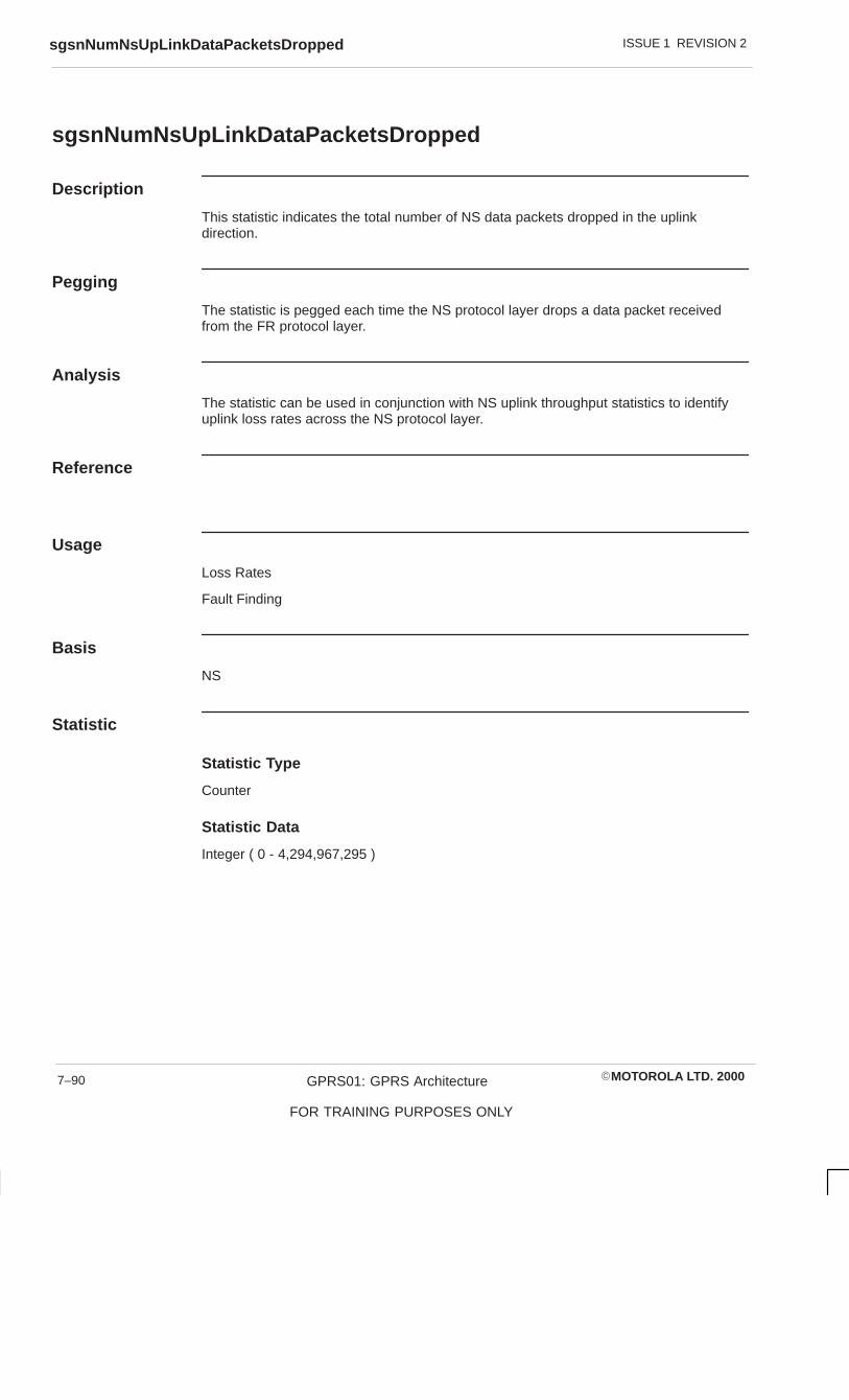
ISSUE 1 REVISION 2sgsnNumNsUpLinkDataPacketsDropped
�MOTOROLA LTD. 2000GPRS01: GPRS Architecture
FOR TRAINING PURPOSES ONLY
7–90
sgsnNumNsUpLinkDataPacketsDropped
Description
This statistic indicates the total number of NS data packets dropped in the uplinkdirection.
Pegging
The statistic is pegged each time the NS protocol layer drops a data packet receivedfrom the FR protocol layer.
Analysis
The statistic can be used in conjunction with NS uplink throughput statistics to identifyuplink loss rates across the NS protocol layer.
Reference
Usage
Loss Rates
Fault Finding
Basis
NS
Statistic
Statistic Type
Counter
Statistic Data
Integer ( 0 - 4,294,967,295 )

ISSUE 1 REVISION 2 sgsnNumNsDownLinkDataPacketsDropped
�MOTOROLA LTD. 2000 GPRS01: GPRS Architecture
FOR TRAINING PURPOSES ONLY
7–91
sgsnNumNsDownLinkDataPacketsDropped
Description
This statistic indicates the total number of NS data packets dropped in the downlinkdirection.
Pegging
The statistic is pegged each time the NS protocol layer drops a data packet receivedfrom the BSSGP protocol layer.
Analysis
The statistic can be used in conjunction with NS downlink throughput statistics to identifydownlink loss rates across the NS protocol layer.
Reference
Usage
Loss Rates
Fault Finding
Basis
GTP Gn
Statistic
Statistic Type
Counter
Statistic Data
Integer ( 0 - 4,294,967,295 )

ISSUE 1 REVISION 2sgsnNumL3mmAttachReqRcvd
�MOTOROLA LTD. 2000GPRS01: GPRS Architecture
FOR TRAINING PURPOSES ONLY
7–92
sgsnNumL3mmAttachReqRcvd
Description
This statistic indicates the total number of L3MM Attach Requests received.
Pegging
The statistic is pegged when the SGSN receives an Attach Request from a MS.
Analysis
Reference
Usage
Network Planning
Congestion Identification
Quality of Service Issues
Basis
L3MM
Statistic
Statistic Type
Counter
Statistic Data
Integer ( 0 - 4,294,967,295 )

ISSUE 1 REVISION 2 sgsnNumL3mmAttachAcceptSent
�MOTOROLA LTD. 2000 GPRS01: GPRS Architecture
FOR TRAINING PURPOSES ONLY
7–93
sgsnNumL3mmAttachAcceptSent
Description
This statistic indicates the total number of L3MM Attach Accepts sent.
Pegging
The statistic is pegged when the SGSN sends an Attach Accept to a MS.
Analysis
Reference
Usage
Network Planning
Congestion Identification
Quality of Service Issues
Basis
L3MM
Statistic
Statistic Type
Counter
Statistic Data
Integer ( 0 - 4,294,967,295 )

ISSUE 1 REVISION 2sgsnNumL3mmAttachRejectSent
�MOTOROLA LTD. 2000GPRS01: GPRS Architecture
FOR TRAINING PURPOSES ONLY
7–94
sgsnNumL3mmAttachRejectSent
Description
This statistic indicates the total number of L3MM Attach Rejects sent.
Pegging
The statistic is pegged when the SGSN sends an Attach Reject to a MS.
Analysis
Reference
Usage
Network Planning
Congestion Identification
Quality of Service Issues
Basis
L3MM
Statistic
Statistic Type
Counter
Statistic Data
Integer ( 0 - 4,294,967,295 )
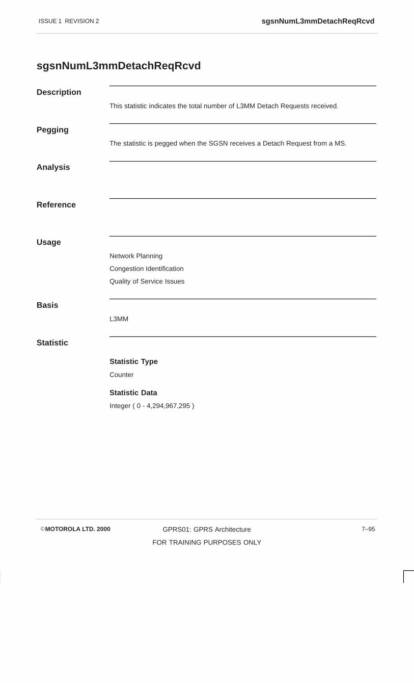
ISSUE 1 REVISION 2 sgsnNumL3mmDetachReqRcvd
�MOTOROLA LTD. 2000 GPRS01: GPRS Architecture
FOR TRAINING PURPOSES ONLY
7–95
sgsnNumL3mmDetachReqRcvd
Description
This statistic indicates the total number of L3MM Detach Requests received.
Pegging
The statistic is pegged when the SGSN receives a Detach Request from a MS.
Analysis
Reference
Usage
Network Planning
Congestion Identification
Quality of Service Issues
Basis
L3MM
Statistic
Statistic Type
Counter
Statistic Data
Integer ( 0 - 4,294,967,295 )

ISSUE 1 REVISION 2sgsnNumL3mmDetachAcceptSent
�MOTOROLA LTD. 2000GPRS01: GPRS Architecture
FOR TRAINING PURPOSES ONLY
7–96
sgsnNumL3mmDetachAcceptSent
Description
This statistic indicates the total number of L3MM Detach Accepts sent.
Pegging
The statistic is pegged when the SGSN sends a Detach Request to a MS.
Analysis
Reference
Usage
Network Planning
Congestion Identification
Quality of Service Issues
Basis
L3MM
Statistic
Statistic Type
Counter
Statistic Data
Integer ( 0 - 4,294,967,295 )

ISSUE 1 REVISION 2 sgsnNumL3mmSessionActivateReqRcvd
�MOTOROLA LTD. 2000 GPRS01: GPRS Architecture
FOR TRAINING PURPOSES ONLY
7–97
sgsnNumL3mmSessionActivateReqRcvd
Description
This statistic indicates the total number of L3MM Session Activate requests received.
Pegging
The statistic is pegged when the SGSN receives a Session Activation Request from aMS.
Analysis
Reference
Usage
Network Planning
Congestion Identification
Quality of Service Issues
Basis
L3MM
Statistic
Statistic Type
Counter
Statistic Data
Integer ( 0 - 4,294,967,295 )

ISSUE 1 REVISION 2sgsnNumL3mmSessionActivateAcceptSent
�MOTOROLA LTD. 2000GPRS01: GPRS Architecture
FOR TRAINING PURPOSES ONLY
7–98
sgsnNumL3mmSessionActivateAcceptSent
Description
This statistic indicates the total number of L3MM Session Activate accepts sent.
Pegging
The statistic is pegged when the SGSN sends a Session Activation Accept to a MS.
Analysis
Reference
Usage
Network Planning
Congestion Identification
Quality of Service Issues
Basis
L3MM
Statistic
Statistic Type
Counter
Statistic Data
Integer ( 0 - 4,294,967,295 )

ISSUE 1 REVISION 2 sgsnNumL3mmSessionActivateRejectSent
�MOTOROLA LTD. 2000 GPRS01: GPRS Architecture
FOR TRAINING PURPOSES ONLY
7–99
sgsnNumL3mmSessionActivateRejectSent
Description
This statistic indicates the total number of L3MM Session Activate rejects sent.
Pegging
The statistic is pegged when the SGSN sends a Session Activation Reject to a MS.
Analysis
Reference
Usage
Network Planning
Congestion Identification
Quality of Service Issues
Basis
L3MM
Statistic
Statistic Type
Counter
Statistic Data
Integer ( 0 - 4,294,967,295 )

ISSUE 1 REVISION 2sgsnNumL3mmSessionDeactivateReqRcvd
�MOTOROLA LTD. 2000GPRS01: GPRS Architecture
FOR TRAINING PURPOSES ONLY
7–100
sgsnNumL3mmSessionDeactivateReqRcvd
Description
This statistic indicates the total number of L3MM Session Deactivate requests received.
Pegging
The statistic is pegged when the SGSN receives a Session Deactivation Request from aMS.
Analysis
Reference
Usage
Network Planning
Congestion Identification
Quality of Service Issues
Basis
L3MM
Statistic
Statistic Type
Counter
Statistic Data
Integer ( 0 - 4,294,967,295 )

ISSUE 1 REVISION 2 sgsnNumL3mmSessionDeactivateAcceptSent
�MOTOROLA LTD. 2000 GPRS01: GPRS Architecture
FOR TRAINING PURPOSES ONLY
7–101
sgsnNumL3mmSessionDeactivateAcceptSent
Description
This statistic indicates the total number of L3MM Session Deactivate accepts sent.
Pegging
The statistic is pegged when the SGSN sends a Session Deactivation Accept to a MS.
Analysis
Reference
Usage
Network Planning
Congestion Identification
Quality of Service Issues
Basis
L3MM
Statistic
Statistic Type
Counter
Statistic Data
Integer ( 0 - 4,294,967,295 )

ISSUE 1 REVISION 2sgsnNumL3mmRaUpdateReqRcvd
�MOTOROLA LTD. 2000GPRS01: GPRS Architecture
FOR TRAINING PURPOSES ONLY
7–102
sgsnNumL3mmRaUpdateReqRcvd
Description
This statistic indicates the total number of L3MM RA Update requests received.
Pegging
The statistic is pegged when the SGSN receives a RA Update Request from a MS.
Analysis
Reference
Usage
Network Planning
Congestion Identification
Quality of Service Issues
Basis
L3MM
Statistic
Statistic Type
Counter
Statistic Data
Integer ( 0 - 4,294,967,295 )

ISSUE 1 REVISION 2 sgsnNumL3mmRaUpdateAcceptSent
�MOTOROLA LTD. 2000 GPRS01: GPRS Architecture
FOR TRAINING PURPOSES ONLY
7–103
sgsnNumL3mmRaUpdateAcceptSent
Description
This statistic indicates the total number of L3MM RA Update accepts sent.
Pegging
The statistic is pegged when the SGSN sends a RA Update Accept to a MS.
Analysis
Reference
Usage
Network Planning
Congestion Identification
Quality of Service Issues
Basis
L3MM
Statistic
Statistic Type
Counter
Statistic Data
Integer ( 0 - 4,294,967,295 )
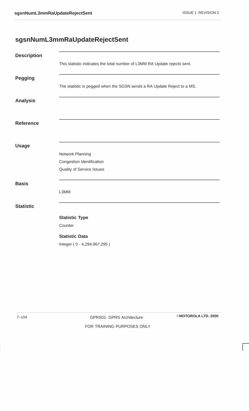
ISSUE 1 REVISION 2sgsnNumL3mmRaUpdateRejectSent
�MOTOROLA LTD. 2000GPRS01: GPRS Architecture
FOR TRAINING PURPOSES ONLY
7–104
sgsnNumL3mmRaUpdateRejectSent
Description
This statistic indicates the total number of L3MM RA Update rejects sent.
Pegging
The statistic is pegged when the SGSN sends a RA Update Reject to a MS.
Analysis
Reference
Usage
Network Planning
Congestion Identification
Quality of Service Issues
Basis
L3MM
Statistic
Statistic Type
Counter
Statistic Data
Integer ( 0 - 4,294,967,295 )

ISSUE 1 REVISION 2 sgsnNumL3mmMsPagingReqSent
�MOTOROLA LTD. 2000 GPRS01: GPRS Architecture
FOR TRAINING PURPOSES ONLY
7–105
sgsnNumL3mmMsPagingReqSent
Description
This statistic indicates the total number of L3MM MS paging requests sent (not thenumber of paging PCUs, in case a page request needs to be sent to multiple PCUs).
Pegging
The statistic is pegged when the SGSN sends a MS Paging Request to a MS.
Analysis
Reference
Usage
Network Planning
Congestion Identification
Quality of Service Issues
Basis
L3MM
Statistic
Statistic Type
Counter
Statistic Data
Integer ( 0 - 4,294,967,295 )

ISSUE 1 REVISION 2sgsnNumL3mmSuccessfulPages
�MOTOROLA LTD. 2000GPRS01: GPRS Architecture
FOR TRAINING PURPOSES ONLY
7–106
sgsnNumL3mmSuccessfulPages
Description
This statistic indicates the total number of successful pages (where the paged MS issuccessfully located).
Pegging
Analysis
Reference
Usage
Network Planning
Congestion Identification
Quality of Service Issues
Basis
L3MM
Statistic
Statistic Type
Counter
Statistic Data
Integer ( 0 - 4,294,967,295 )

ISSUE 1 REVISION 2 sgsnCurrentNumGprsAttachedMS
�MOTOROLA LTD. 2000 GPRS01: GPRS Architecture
FOR TRAINING PURPOSES ONLY
7–107
sgsnCurrentNumGprsAttachedMS
Description
This statistic indicates the current number of GPRS attached MS.
Pegging
Analysis
Reference
Usage
Network Planning
Congestion Identification
Basis
Miscellaneous
Statistic
Statistic Type
Gauge
Statistic Data
Integer ( 0 - 4,294,967,295 )

ISSUE 1 REVISION 2sgsnCurrentNumActivePdpSession
�MOTOROLA LTD. 2000GPRS01: GPRS Architecture
FOR TRAINING PURPOSES ONLY
7–108
sgsnCurrentNumActivePdpSession
Description
This statistic indicates the current number of active PDP sessions.
Pegging
Analysis
Reference
Usage
Network Planning
Congestion Identification
Basis
Miscellaneous
Statistic
Statistic Type
Gauge
Statistic Data
Integer ( 0 - 4,294,967,295 )

ISSUE 1 REVISION 2 sgsnNumCells
�MOTOROLA LTD. 2000 GPRS01: GPRS Architecture
FOR TRAINING PURPOSES ONLY
7–109
sgsnNumCells
Description
This statistic indicates the total number of cells.
Pegging
Analysis
Reference
Usage
Network Planning
Congestion Identification
Basis
Miscellaneous
Statistic
Statistic Type
Gauge
Statistic Data
Integer ( 0 - 4,294,967,295 )

ISSUE 1 REVISION 2sgsnNumCells
�MOTOROLA LTD. 2000GPRS01: GPRS Architecture
FOR TRAINING PURPOSES ONLY
7–110

ISSUE 1 REVISION 2 sgsnNumBssgpDownLinkDataPacketsSent
�MOTOROLA LTD. 2000 GPRS01: GPRS Architecture
FOR TRAINING PURPOSES ONLY
7–111
sgsnNumBssgpDownLinkDataPacketsSent
Description
This BSSGP attribute indicates the total number of BSSGP data packets sent to the NSprotocol layer.
Pegging
The statistic is pegged each time the BSSGP protocol layer sends a data packet to theNS protocol layer.
Analysis
The statistic can be used in conjunction with sgsnNumBssgpDownLinkDataPacketsRcvd to show the SGSN data packet throughput in the downlink direction across theBSSGP protocol layer.
Reference
?
Usage
Network Planning
Congestion Identification
Loss Rates
Fault Finding
Basis
BSSGP
Statistic
Statistic Type
Counter
Statistic Data
Integer ( 0 - 4,294,967,295 )
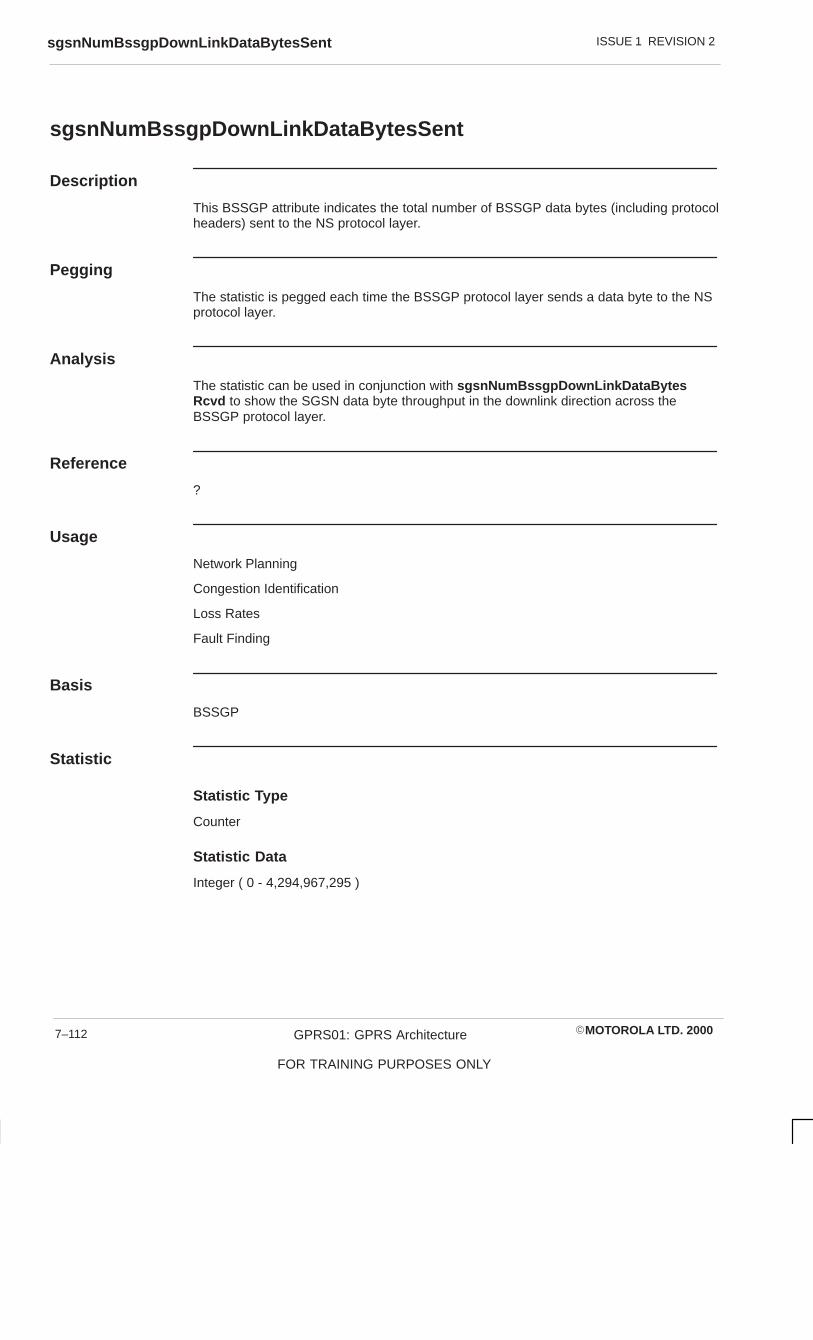
ISSUE 1 REVISION 2sgsnNumBssgpDownLinkDataBytesSent
�MOTOROLA LTD. 2000GPRS01: GPRS Architecture
FOR TRAINING PURPOSES ONLY
7–112
sgsnNumBssgpDownLinkDataBytesSent
Description
This BSSGP attribute indicates the total number of BSSGP data bytes (including protocolheaders) sent to the NS protocol layer.
Pegging
The statistic is pegged each time the BSSGP protocol layer sends a data byte to the NSprotocol layer.
Analysis
The statistic can be used in conjunction with sgsnNumBssgpDownLinkDataBytesRcvd to show the SGSN data byte throughput in the downlink direction across theBSSGP protocol layer.
Reference
?
Usage
Network Planning
Congestion Identification
Loss Rates
Fault Finding
Basis
BSSGP
Statistic
Statistic Type
Counter
Statistic Data
Integer ( 0 - 4,294,967,295 )

ISSUE 1 REVISION 2 sgsnNumBssgpUpLinkDataPacketsRcvd
�MOTOROLA LTD. 2000 GPRS01: GPRS Architecture
FOR TRAINING PURPOSES ONLY
7–113
sgsnNumBssgpUpLinkDataPacketsRcvd
Description
This BSSGP attribute indicates the total number of BSSGP data packets received fromNS protocol layer.
Pegging
The statistic is pegged each time the BSSGP protocol layer receives a data packet fromthe NS protocol layer.
Analysis
The statistic can be used in conjunction with sgsnNumBssgpUpLinkDataPacketsSentto show the SGSN data packet throughput in the uplink direction across the BSSGPprotocol layer.
Reference
?
Usage
Network Planning
Congestion Identification
Loss Rates
Fault Finding
Basis
BSSGP
Statistic
Statistic Type
Counter
Statistic Data
Integer ( 0 - 4,294,967,295 )
ISSUE 1 REVISION 2sgsnNumBssgpUpLinkDataBytesRcvd
�MOTOROLA LTD. 2000GPRS01: GPRS Architecture
FOR TRAINING PURPOSES ONLY
7–114
sgsnNumBssgpUpLinkDataBytesRcvd
Description
This BSSGP attribute indicates the total number of BSSGP data bytes (including protocolheaders) received from NS protocol layer.
Pegging
The statistic is pegged each time the BSSGP protocol layer receives a data byte from theNS protocol layer.
Analysis
The statistic can be used in conjunction with sgsnNumBssgpUpLinkDataBytesSent toshow the SGSN data byte throughput in the uplink direction across the BSSGP protocollayer.
Reference
?
Usage
Network Planning
Congestion Identification
Loss Rates
Fault Finding
Basis
BSSGP
Statistic
Statistic Type
Counter
Statistic Data
Integer ( 0 - 4,294,967,295 )

ISSUE 1 REVISION 2 sgsnNumBssgpUpLinkDataPacketsSent
�MOTOROLA LTD. 2000 GPRS01: GPRS Architecture
FOR TRAINING PURPOSES ONLY
7–115
sgsnNumBssgpUpLinkDataPacketsSent
Description
This BSSGP attribute indicates the total number of BSSGP data packets sent to the LLCprotocol layer.
Pegging
The statistic is pegged each time the BSSGP protocol layer sends a data packet to theLLC protocol layer.
Analysis
The statistic can be used in conjunction with sgsnNumBssgpUpLinkDataPacketsRcvdto show the SGSN data packet throughput in the uplink direction across the BSSGPprotocol layer.
Reference
?
Usage
Network Planning
Congestion Identification
Loss Rates
Fault Finding
Basis
BSSGP
Statistic
Statistic Type
Counter
Statistic Data
Integer ( 0 - 4,294,967,295 )

ISSUE 1 REVISION 2sgsnNumBssgpUpLinkDataBytesSent
�MOTOROLA LTD. 2000GPRS01: GPRS Architecture
FOR TRAINING PURPOSES ONLY
7–116
sgsnNumBssgpUpLinkDataBytesSent
Description
This BSSGP attribute indicates the total number of BSSGP data bytes (including protocolheaders) sent to the LLC protocol layer.
Pegging
The statistic is pegged each time the BSSGP protocol layer sends a data byte to the LLCprotocol layer.
Analysis
The statistic can be used in conjunction with sgsnNumBssgpUpLinkDataBytesRcvd toshow the SGSN data byte throughput in the uplink direction across the BSSGP protocollayer.
Reference
?
Usage
Network Planning
Congestion Identification
Loss Rates
Fault Finding
Basis
BSSGP
Statistic
Statistic Type
Counter
Statistic Data
Integer ( 0 - 4,294,967,295 )

ISSUE 1 REVISION 2 sgsnNumBssgpDownLinkDataPacketsRcvd
�MOTOROLA LTD. 2000 GPRS01: GPRS Architecture
FOR TRAINING PURPOSES ONLY
7–117
sgsnNumBssgpDownLinkDataPacketsRcvd
Description
This BSSGP attribute indicates the total number of BSSGP data packets received fromthe LLC protocol layer.
Pegging
The statistic is pegged each time the BSSGP protocol layer receives a data packet fromthe LLC protocol layer.
Analysis
The statistic can be used in conjunction with sgsnNumBssgpDownLinkDataPacketsSent to show the SGSN data packet throughput in the downlink direction across theBSSGP protocol layer.
Reference
?
Usage
Network Planning
Congestion Identification
Loss Rates
Fault Finding
Basis
BSSGP
Statistic
Statistic Type
Counter
Statistic Data
Integer ( 0 - 4,294,967,295 )
ISSUE 1 REVISION 2sgsnNumBssgpDownLinkDataBytesRcvd
�MOTOROLA LTD. 2000GPRS01: GPRS Architecture
FOR TRAINING PURPOSES ONLY
7–118
sgsnNumBssgpDownLinkDataBytesRcvd
Description
This BSSGP attribute indicates the total number of BSSGP data bytes (including protocolheaders) received from the LLC protocol layer.
Pegging
The statistic is pegged each time the BSSGP protocol layer receives a data byte from theLLC protocol layer.
Analysis
The statistic can be used in conjunction with sgsnNumBssgpDownLinkDataBytesSentto show the SGSN data byte throughput in the downlink direction across the BSSGPprotocol layer.
Reference
?
Usage
Network Planning
Congestion Identification
Loss Rates
Fault Finding
Basis
BSSGP
Statistic
Statistic Type
Counter
Statistic Data
Integer ( 0 - 4,294,967,295 )

ISSUE 1 REVISION 2 sgsnNumBssgpUpLinkDataPacketsDropped
�MOTOROLA LTD. 2000 GPRS01: GPRS Architecture
FOR TRAINING PURPOSES ONLY
7–119
sgsnNumBssgpUpLinkDataPacketsDropped
Description
This BSSGP attribute indicates the total number of BSSGP data packets dropped in theuplink direction.
Pegging
The statistic is pegged each time the BSSGP protocol layer drops a data packet receivedfrom the NS protocol layer.
Analysis
The statistic can be used in conjunction with BSSGP uplink throughput statistics toidentify uplink loss rates across the BSSGP protocol layer.
Reference
?
Usage
Loss Rates
Fault Finding
Basis
BSSGP
Statistic
Statistic Type
Counter
Statistic Data
Integer ( 0 - 4,294,967,295 )

ISSUE 1 REVISION 2sgsnNumBssgpDownLinkDataPacketsDropped
�MOTOROLA LTD. 2000GPRS01: GPRS Architecture
FOR TRAINING PURPOSES ONLY
7–120
sgsnNumBssgpDownLinkDataPacketsDropped
Description
This BSSGP attribute indicates the total number of BSSGP data packets dropped in thedownlink direction.
Pegging
The statistic is pegged each time the BSSGP protocol layer drops a data packet receivedfrom the LLC protocol layer.
Analysis
The statistic can be used in conjunction with BSSGP downlink throughput statistics toidentify downlink loss rates across the BSSGP protocol layer.
Reference
?
Usage
Loss Rates
Fault Finding
Basis
BSSGP
Statistic
Statistic Type
Counter
Statistic Data
Integer ( 0 - 4,294,967,295 )

ISSUE 1 REVISION 2 sgsnNumNsDownLinkDataPacketsRcvd
�MOTOROLA LTD. 2000 GPRS01: GPRS Architecture
FOR TRAINING PURPOSES ONLY
7–121
sgsnNumNsDownLinkDataPacketsRcvd
Description
This statistic indicates the total number of NS data packets received from the BSSGPprotocol layer.
Pegging
The statistic is pegged each time the NS protocol layer receives a data packet from theBSSGP protocol layer.
Analysis
The statistic can be used in conjunction with sgsnNumNsDownLinkDataPacketsSentto show the SGSN data packet throughput in the downlink direction across the NSprotocol layer.
Reference
?
Usage
Network Planning
Congestion Identification
Loss Rates
Fault Finding
Basis
NS
Statistic
Statistic Type
Counter
Statistic Data
Integer ( 0 - 4,294,967,295 )

ISSUE 1 REVISION 2sgsnNumNsDownLinkDataBytesRcvd
�MOTOROLA LTD. 2000GPRS01: GPRS Architecture
FOR TRAINING PURPOSES ONLY
7–122
sgsnNumNsDownLinkDataBytesRcvd
Description
This statistic indicates the total number of NS data bytes (including protocol headers)received from the BSSGP protocol layer.
Pegging
The statistic is pegged each time the NS protocol layer receives a data byte from theBSSGP protocol layer.
Analysis
The statistic can be used in conjunction with sgsnNumNsDownLinkDataBytesSent toshow the SGSN data byte throughput in the downlink direction across the NS protocollayer.
Reference
?
Usage
Network Planning
Congestion Identification
Loss Rates
Fault Finding
Basis
NS
Statistic
Statistic Type
Counter
Statistic Data
Integer ( 0 - 4,294,967,295 )
ISSUE 1 REVISION 2 sgsnNumNsUpLinkDataPacketsSent
�MOTOROLA LTD. 2000 GPRS01: GPRS Architecture
FOR TRAINING PURPOSES ONLY
7–123
sgsnNumNsUpLinkDataPacketsSent
Description
This statistic indicates the total number of NS data packets sent to the BSSGP protocollayer.
Pegging
The statistic is pegged each time the NS protocol layer sends a data packet to theBSSGP protocol layer.
Analysis
The statistic can be used in conjunction with sgsnNumNsUpLinkDataPacketsRcvd toshow the SGSN data packet throughput in the uplink direction across the NS protocollayer.
Reference
?
Usage
Network Planning
Congestion Identification
Loss Rates
Fault Finding
Basis
NS
Statistic
Statistic Type
Counter
Statistic Data
Integer ( 0 - 4,294,967,295 )

ISSUE 1 REVISION 2sgsnNumNsUpLinkDataBytesSent
�MOTOROLA LTD. 2000GPRS01: GPRS Architecture
FOR TRAINING PURPOSES ONLY
7–124
sgsnNumNsUpLinkDataBytesSent
Description
This statistic indicates the total number of NS data bytes (including protocol headers)sent to the BSSGP protocol layer.
Pegging
The statistic is pegged each time the NS protocol layer sends a data byte to the BSSGPprotocol layer.
Analysis
The statistic can be used in conjunction with sgsnNumNsUpLinkDataBytesRcvd toshow the SGSN data byte throughput in the uplink direction across the NS protocol layer.
Reference
?
Usage
Network Planning
Congestion Identification
Loss Rates
Fault Finding
Basis
NS
Statistic
Statistic Type
Counter
Statistic Data
Integer ( 0 - 4,294,967,295 )

ISSUE 1 REVISION 2 sgsnNumNsUpLinkDataPacketsRcvd
�MOTOROLA LTD. 2000 GPRS01: GPRS Architecture
FOR TRAINING PURPOSES ONLY
7–125
sgsnNumNsUpLinkDataPacketsRcvd
Description
This statistic indicates the total number of NS data packets received from the FR protocollayer.
Pegging
The statistic is pegged each time the NS protocol layer receives a data packet from theFR protocol layer.
Analysis
The statistic can be used in conjunction with sgsnNumNsUpLinkDataPacketsSent toshow the SGSN data packet throughput in the uplink direction across the NS protocollayer.
Reference
?
Usage
Network Planning
Congestion Identification
Loss Rates
Fault Finding
Basis
NS
Statistic
Statistic Type
Counter
Statistic Data
Integer ( 0 - 4,294,967,295 )

ISSUE 1 REVISION 2sgsnNumNsUpLinkDataBytesRcvd
�MOTOROLA LTD. 2000GPRS01: GPRS Architecture
FOR TRAINING PURPOSES ONLY
7–126
sgsnNumNsUpLinkDataBytesRcvd
Description
This statistic indicates the total number of NS data bytes (including protocol headers)received from the FR protocol layer.
Pegging
The statistic is pegged each time the NS protocol layer receives a data byte from the FRprotocol layer.
Analysis
The statistic can be used in conjunction with sgsnNumNsUpLinkDataBytesSent toshow the SGSN data byte throughput in the uplink direction across the NS protocol layer.
Reference
?
Usage
Network Planning
Congestion Identification
Loss Rates
Fault Finding
Basis
NS
Statistic
Statistic Type
Counter
Statistic Data
Integer ( 0 - 4,294,967,295 )

ISSUE 1 REVISION 2 sgsnNumNsDownLinkDataPacketsSent
�MOTOROLA LTD. 2000 GPRS01: GPRS Architecture
FOR TRAINING PURPOSES ONLY
7–127
sgsnNumNsDownLinkDataPacketsSent
Description
This statistic indicates the total number of NS data packets sent to the FR protocol layer.
Pegging
The statistic is pegged each time the NS protocol layer sends a data packet to the FRprotocol layer.
Analysis
The statistic can be used in conjunction with sgsnNumNsDownLinkDataPacketsRcvdto show the SGSN data packet throughput in the downlink direction across the NSprotocol layer.
Reference
?
Usage
Network Planning
Congestion Identification
Loss Rates
Fault Finding
Basis
NS
Statistic
Statistic Type
Counter
Statistic Data
Integer ( 0 - 4,294,967,295 )

ISSUE 1 REVISION 2sgsnNumNsDownLinkDataBytesSent
�MOTOROLA LTD. 2000GPRS01: GPRS Architecture
FOR TRAINING PURPOSES ONLY
7–128
sgsnNumNsDownLinkDataBytesSent
Description
This statistic indicates the total number of NS data bytes (including protocol headers)sent to the FR protocol layer.
Pegging
The statistic is pegged each time the NS protocol layer sends a data byte to the FRprotocol layer.
Analysis
The statistic can be used in conjunction with sgsnNumNsDownLinkDataBytesRcvd toshow the SGSN data byte throughput in the downlink direction across the NS protocollayer.
Reference
?
Usage
Network Planning
Congestion Identification
Loss Rates
Fault Finding
Basis
NS
Statistic
Statistic Type
Counter
Statistic Data
Integer ( 0 - 4,294,967,295 )

ISSUE 1 REVISION 2 sgsnNumNsUpLinkDataPacketsDropped
�MOTOROLA LTD. 2000 GPRS01: GPRS Architecture
FOR TRAINING PURPOSES ONLY
7–129
sgsnNumNsUpLinkDataPacketsDropped
Description
This statistic indicates the total number of NS data packets dropped in the uplinkdirection.
Pegging
The statistic is pegged each time the NS protocol layer drops a data packet receivedfrom the FR protocol layer.
Analysis
The statistic can be used in conjunction with NS uplink throughput statistics to identifyuplink loss rates across the NS protocol layer.
Reference
?
Usage
Loss Rates
Fault Finding
Basis
NS
Statistic
Statistic Type
Counter
Statistic Data
Integer ( 0 - 4,294,967,295 )

ISSUE 1 REVISION 2sgsnNumNsDownLinkDataPacketsDropped
�MOTOROLA LTD. 2000GPRS01: GPRS Architecture
FOR TRAINING PURPOSES ONLY
7–130
sgsnNumNsDownLinkDataPacketsDropped
Description
This statistic indicates the total number of NS data packets dropped in the downlinkdirection.
Pegging
The statistic is pegged each time the NS protocol layer drops a data packet receivedfrom the BSSGP protocol layer.
Analysis
The statistic can be used in conjunction with NS downlink throughput statistics to identifydownlink loss rates across the NS protocol layer.
Reference
?
Usage
Loss Rates
Fault Finding
Basis
GTP Gn
Statistic
Statistic Type
Counter
Statistic Data
Integer ( 0 - 4,294,967,295 )

ISSUE 1 REVISION 2 FR stats
�MOTOROLA LTD. 2000 GPRS01: GPRS Architecture
FOR TRAINING PURPOSES ONLY
7–131
FR statsDetails of Fr statistics attributes not available at this time.

ISSUE 1 REVISION 2sgsnNumL3mmAttachReqRcvd
�MOTOROLA LTD. 2000GPRS01: GPRS Architecture
FOR TRAINING PURPOSES ONLY
7–132
sgsnNumL3mmAttachReqRcvd
Description
This statistic indicates the total number of L3MM Attach Requests received.
Pegging
The statistic is pegged when the SGSN receives an Attach Request from a MS.
Analysis
?
Reference
?
Usage
Network Planning
Congestion Identification
Quality of Service Issues
Basis
L3MM
Statistic
Statistic Type
Counter
Statistic Data
Integer ( 0 - 4,294,967,295 )

ISSUE 1 REVISION 2 sgsnNumL3mmAttachAcceptSent
�MOTOROLA LTD. 2000 GPRS01: GPRS Architecture
FOR TRAINING PURPOSES ONLY
7–133
sgsnNumL3mmAttachAcceptSent
Description
This statistic indicates the total number of L3MM Attach Accepts sent.
Pegging
The statistic is pegged when the SGSN sends an Attach Accept to a MS.
Analysis
?
Reference
?
Usage
Network Planning
Congestion Identification
Quality of Service Issues
Basis
L3MM
Statistic
Statistic Type
Counter
Statistic Data
Integer ( 0 - 4,294,967,295 )

ISSUE 1 REVISION 2sgsnNumL3mmAttachRejectSent
�MOTOROLA LTD. 2000GPRS01: GPRS Architecture
FOR TRAINING PURPOSES ONLY
7–134
sgsnNumL3mmAttachRejectSent
Description
This statistic indicates the total number of L3MM Attach Rejects sent.
Pegging
The statistic is pegged when the SGSN sends an Attach Reject to a MS.
Analysis
?
Reference
?
Usage
Network Planning
Congestion Identification
Quality of Service Issues
Basis
L3MM
Statistic
Statistic Type
Counter
Statistic Data
Integer ( 0 - 4,294,967,295 )

ISSUE 1 REVISION 2 sgsnNumL3mmDetachReqRcvd
�MOTOROLA LTD. 2000 GPRS01: GPRS Architecture
FOR TRAINING PURPOSES ONLY
7–135
sgsnNumL3mmDetachReqRcvd
Description
This statistic indicates the total number of L3MM Detach Requests received.
Pegging
The statistic is pegged when the SGSN receives a Detach Request from a MS.
Analysis
?
Reference
?
Usage
Network Planning
Congestion Identification
Quality of Service Issues
Basis
L3MM
Statistic
Statistic Type
Counter
Statistic Data
Integer ( 0 - 4,294,967,295 )

ISSUE 1 REVISION 2sgsnNumL3mmDetachAcceptSent
�MOTOROLA LTD. 2000GPRS01: GPRS Architecture
FOR TRAINING PURPOSES ONLY
7–136
sgsnNumL3mmDetachAcceptSent
Description
This statistic indicates the total number of L3MM Detach Accepts sent.
Pegging
The statistic is pegged when the SGSN sends a Detach Request to a MS.
Analysis
?
Reference
?
Usage
Network Planning
Congestion Identification
Quality of Service Issues
Basis
L3MM
Statistic
Statistic Type
Counter
Statistic Data
Integer ( 0 - 4,294,967,295 )

ISSUE 1 REVISION 2 sgsnNumL3mmSessionActivateReqRcvd
�MOTOROLA LTD. 2000 GPRS01: GPRS Architecture
FOR TRAINING PURPOSES ONLY
7–137
sgsnNumL3mmSessionActivateReqRcvd
Description
This statistic indicates the total number of L3MM Session Activate requests received.
Pegging
The statistic is pegged when the SGSN receives a Session Activation Request from aMS.
Analysis
?
Reference
?
Usage
Network Planning
Congestion Identification
Quality of Service Issues
Basis
L3MM
Statistic
Statistic Type
Counter
Statistic Data
Integer ( 0 - 4,294,967,295 )

ISSUE 1 REVISION 2sgsnNumL3mmSessionActivateAcceptSent
�MOTOROLA LTD. 2000GPRS01: GPRS Architecture
FOR TRAINING PURPOSES ONLY
7–138
sgsnNumL3mmSessionActivateAcceptSent
Description
This statistic indicates the total number of L3MM Session Activate accepts sent.
Pegging
The statistic is pegged when the SGSN sends a Session Activation Accept to a MS.
Analysis
?
Reference
?
Usage
Network Planning
Congestion Identification
Quality of Service Issues
Basis
L3MM
Statistic
Statistic Type
Counter
Statistic Data
Integer ( 0 - 4,294,967,295 )
ISSUE 1 REVISION 2 sgsnNumL3mmSessionActivateRejectSent
�MOTOROLA LTD. 2000 GPRS01: GPRS Architecture
FOR TRAINING PURPOSES ONLY
7–139
sgsnNumL3mmSessionActivateRejectSent
Description
This statistic indicates the total number of L3MM Session Activate rejects sent.
Pegging
The statistic is pegged when the SGSN sends a Session Activation Reject to a MS.
Analysis
?
Reference
?
Usage
Network Planning
Congestion Identification
Quality of Service Issues
Basis
L3MM
Statistic
Statistic Type
Counter
Statistic Data
Integer ( 0 - 4,294,967,295 )

ISSUE 1 REVISION 2sgsnNumL3mmSessionDeactivateReqRcvd
�MOTOROLA LTD. 2000GPRS01: GPRS Architecture
FOR TRAINING PURPOSES ONLY
7–140
sgsnNumL3mmSessionDeactivateReqRcvd
Description
This statistic indicates the total number of L3MM Session Deactivate requests received.
Pegging
The statistic is pegged when the SGSN receives a Session Deactivation Request from aMS.
Analysis
?
Reference
?
Usage
Network Planning
Congestion Identification
Quality of Service Issues
Basis
L3MM
Statistic
Statistic Type
Counter
Statistic Data
Integer ( 0 - 4,294,967,295 )

ISSUE 1 REVISION 2 sgsnNumL3mmSessionDeactivateAcceptSent
�MOTOROLA LTD. 2000 GPRS01: GPRS Architecture
FOR TRAINING PURPOSES ONLY
7–141
sgsnNumL3mmSessionDeactivateAcceptSent
Description
This statistic indicates the total number of L3MM Session Deactivate accepts sent.
Pegging
The statistic is pegged when the SGSN sends a Session Deactivation Accept to a MS.
Analysis
?
Reference
?
Usage
Network Planning
Congestion Identification
Quality of Service Issues
Basis
L3MM
Statistic
Statistic Type
Counter
Statistic Data
Integer ( 0 - 4,294,967,295 )

ISSUE 1 REVISION 2sgsnNumL3mmRaUpdateReqRcvd
�MOTOROLA LTD. 2000GPRS01: GPRS Architecture
FOR TRAINING PURPOSES ONLY
7–142
sgsnNumL3mmRaUpdateReqRcvd
Description
This statistic indicates the total number of L3MM RA Update requests received.
Pegging
The statistic is pegged when the SGSN receives a RA Update Request from a MS.
Analysis
?
Reference
?
Usage
Network Planning
Congestion Identification
Quality of Service Issues
Basis
L3MM
Statistic
Statistic Type
Counter
Statistic Data
Integer ( 0 - 4,294,967,295 )

ISSUE 1 REVISION 2 sgsnNumL3mmRaUpdateAcceptSent
�MOTOROLA LTD. 2000 GPRS01: GPRS Architecture
FOR TRAINING PURPOSES ONLY
7–143
sgsnNumL3mmRaUpdateAcceptSent
Description
This statistic indicates the total number of L3MM RA Update accepts sent.
Pegging
The statistic is pegged when the SGSN sends a RA Update Accept to a MS.
Analysis
?
Reference
?
Usage
Network Planning
Congestion Identification
Quality of Service Issues
Basis
L3MM
Statistic
Statistic Type
Counter
Statistic Data
Integer ( 0 - 4,294,967,295 )

ISSUE 1 REVISION 2sgsnNumL3mmRaUpdateRejectSent
�MOTOROLA LTD. 2000GPRS01: GPRS Architecture
FOR TRAINING PURPOSES ONLY
7–144
sgsnNumL3mmRaUpdateRejectSent
Description
This statistic indicates the total number of L3MM RA Update rejects sent.
Pegging
The statistic is pegged when the SGSN sends a RA Update Reject to a MS.
Analysis
?
Reference
?
Usage
Network Planning
Congestion Identification
Quality of Service Issues
Basis
L3MM
Statistic
Statistic Type
Counter
Statistic Data
Integer ( 0 - 4,294,967,295 )

ISSUE 1 REVISION 2 sgsnNumL3mmMsPagingReqSent
�MOTOROLA LTD. 2000 GPRS01: GPRS Architecture
FOR TRAINING PURPOSES ONLY
7–145
sgsnNumL3mmMsPagingReqSent
Description
This statistic indicates the total number of L3MM MS paging requests sent (not thenumber of paging PCUs, in case a page request needs to be sent to multiple PCUs).
Pegging
The statistic is pegged when the SGSN sends a MS Paging Request to a MS.
Analysis
?
Reference
?
Usage
Network Planning
Congestion Identification
Quality of Service Issues
Basis
L3MM
Statistic
Statistic Type
Counter
Statistic Data
Integer ( 0 - 4,294,967,295 )

ISSUE 1 REVISION 2sgsnNumL3mmSuccessfulPages
�MOTOROLA LTD. 2000GPRS01: GPRS Architecture
FOR TRAINING PURPOSES ONLY
7–146
sgsnNumL3mmSuccessfulPages
Description
This statistic indicates the total number of successful pages (where the paged MS issuccessfully located).
Pegging
?
Analysis
?
Reference
?
Usage
Network Planning
Congestion Identification
Quality of Service Issues
Basis
L3MM
Statistic
Statistic Type
Counter
Statistic Data
Integer ( 0 - 4,294,967,295 )

ISSUE 1 REVISION 2 sgsnCurrentNumGprsAttachedMS
�MOTOROLA LTD. 2000 GPRS01: GPRS Architecture
FOR TRAINING PURPOSES ONLY
7–147
sgsnCurrentNumGprsAttachedMS
Description
This statistic indicates the current number of GPRS attached MS.
Pegging
?
Analysis
?
Reference
?
Usage
Network Planning
Congestion Identification
Basis
Miscellaneous
Statistic
Statistic Type
Counter
Statistic Data
Integer ( 0 - 4,294,967,295 )

ISSUE 1 REVISION 2sgsnCurrentNumActivePdpSession
�MOTOROLA LTD. 2000GPRS01: GPRS Architecture
FOR TRAINING PURPOSES ONLY
7–148
sgsnCurrentNumActivePdpSession
Description
This statistic indicates the current number of active PDP sessions.
Pegging
?
Analysis
?
Reference
?
Usage
Network Planning
Congestion Identification
Basis
Miscellaneous
Statistic
Statistic Type
Counter
Statistic Data
Integer ( 0 - 4,294,967,295 )

ISSUE 1 REVISION 2 sgsnNumCells
�MOTOROLA LTD. 2000 GPRS01: GPRS Architecture
FOR TRAINING PURPOSES ONLY
7–149
sgsnNumCells
Description
This statistic indicates the total number of cells.
Pegging
?
Analysis
?
Reference
?
Usage
Network Planning
Congestion Identification
Basis
Miscellaneous
Statistic
Statistic Type
Counter
Statistic Data
Integer ( 0 - 4,294,967,295 )
ISSUE 1 REVISION 2sgsnNumCells
�MOTOROLA LTD. 2000GPRS01: GPRS Architecture
FOR TRAINING PURPOSES ONLY
7–150

�MOTOROLA LTD. 2000 GPRS01: GPRS Architecture
FOR TRAINING PURPOSES ONLY
i
Chapter 8
GGSN statistics attributes

ISSUE 1 REVISION 2
�MOTOROLA LTD. 2000GPRS01: GPRS Architecture
FOR TRAINING PURPOSES ONLY
ii

ISSUE 1 REVISION 2
�MOTOROLA LTD. 2000 GPRS01: GPRS Architecture
FOR TRAINING PURPOSES ONLY
iii
Chapter 3GGSN statistics attributes i. . . . . . . . . . . . . . . . . . . . . . . . . . . . . . . . . . . . . . . . . . .
Introduction to Cisco GGSN statistics 3–1. . . . . . . . . . . . . . . . . . . . . . . . . . . . . . . . . . . . . . . . . . Purpose of this chapter 3–1. . . . . . . . . . . . . . . . . . . . . . . . . . . . . . . . . . . . . . . . . . . . . . . . How this chapter is structured 3–1. . . . . . . . . . . . . . . . . . . . . . . . . . . . . . . . . . . . . . . . . . . GGSN OID structure 3–2. . . . . . . . . . . . . . . . . . . . . . . . . . . . . . . . . . . . . . . . . . . . . . . . . . Attributes Tables 3–2. . . . . . . . . . . . . . . . . . . . . . . . . . . . . . . . . . . . . . . . . . . . . . . . . . . . . .
cgprsGtpCurRxPacketQueueSize 3–5. . . . . . . . . . . . . . . . . . . . . . . . . . . . . . . . . . . . . . . . . . . . .
cgprsGtpCurActivatedPDPcontextsCount 3–6. . . . . . . . . . . . . . . . . . . . . . . . . . . . . . . . . . . . . .
cgprsGtpCurUnexpectedRxGpduCount 3–7. . . . . . . . . . . . . . . . . . . . . . . . . . . . . . . . . . . . . . . .
cgprsGtpCurRejectedPDPContextActivationCount 3–8. . . . . . . . . . . . . . . . . . . . . . . . . . . . . .
cgprsGtpTotalPktsDropped 3–9. . . . . . . . . . . . . . . . . . . . . . . . . . . . . . . . . . . . . . . . . . . . . . . . . . .
cgprsGtpDroppedPktsTimeFrame 3–10. . . . . . . . . . . . . . . . . . . . . . . . . . . . . . . . . . . . . . . . . . . . .
cgprsGtpDroppedPktsCount 3–11. . . . . . . . . . . . . . . . . . . . . . . . . . . . . . . . . . . . . . . . . . . . . . . . . .
cgprsGtpCurMeanThroughputForPremiumQos 3–12. . . . . . . . . . . . . . . . . . . . . . . . . . . . . . . . .
cgprsGtpCurMeanThroughputForNormalQos 3–13. . . . . . . . . . . . . . . . . . . . . . . . . . . . . . . . . . .
cgprsGtpCurMeanThroughputForBestEffortQos 3–14. . . . . . . . . . . . . . . . . . . . . . . . . . . . . . . . .
cgprsGtpCurGSNBandwidthResourceUsed 3–15. . . . . . . . . . . . . . . . . . . . . . . . . . . . . . . . . . . .
cgprsGtpGSNTable 3–16. . . . . . . . . . . . . . . . . . . . . . . . . . . . . . . . . . . . . . . . . . . . . . . . . . . . . . . . .
cgprsGtpGSNEntry 3–18. . . . . . . . . . . . . . . . . . . . . . . . . . . . . . . . . . . . . . . . . . . . . . . . . . . . . . . . .
cgprsGtpGSNid 3–19. . . . . . . . . . . . . . . . . . . . . . . . . . . . . . . . . . . . . . . . . . . . . . . . . . . . . . . . . . . .
cgprsGtpGSNEchoFailedNotificationCount 3–20. . . . . . . . . . . . . . . . . . . . . . . . . . . . . . . . . . . . .
cgprsGtpTotalNumAllocIpAddr 3–21. . . . . . . . . . . . . . . . . . . . . . . . . . . . . . . . . . . . . . . . . . . . . . . .
cgprsGtpChargingMsgCount 3–22. . . . . . . . . . . . . . . . . . . . . . . . . . . . . . . . . . . . . . . . . . . . . . . . .
cgprsGtpLastGSNidNoRespToEcho 3–23. . . . . . . . . . . . . . . . . . . . . . . . . . . . . . . . . . . . . . . . . . .
cgprsGtpGSNidOfLastUnexpectedPDPContext 3–24. . . . . . . . . . . . . . . . . . . . . . . . . . . . . . . . .
cgprsGtpTIDOfLastUnexpectedPDPContext 3–25. . . . . . . . . . . . . . . . . . . . . . . . . . . . . . . . . . . .
cgprsGtpRejectReasonOfLastUnexpectedPDPContext 3–26. . . . . . . . . . . . . . . . . . . . . . . . . .
cgprsGtpNumAllocIpAddrTable 3–27. . . . . . . . . . . . . . . . . . . . . . . . . . . . . . . . . . . . . . . . . . . . . . .
cgprsGtpNumAllocIpAddrEntry 3–28. . . . . . . . . . . . . . . . . . . . . . . . . . . . . . . . . . . . . . . . . . . . . . .
cgprsGtpNumAllocIpAddr 3–29. . . . . . . . . . . . . . . . . . . . . . . . . . . . . . . . . . . . . . . . . . . . . . . . . . . .

ISSUE 1 REVISION 2
�MOTOROLA LTD. 2000GPRS01: GPRS Architecture
FOR TRAINING PURPOSES ONLY
iv

ISSUE 1 REVISION 2 Introduction to Cisco GGSN statistics
�MOTOROLA LTD. 2000 GPRS01: GPRS Architecture
FOR TRAINING PURPOSES ONLY
8–1
Introduction to Cisco GGSN statistics
Purpose of thischapter
This chapter describes statistical measurements generated by the Cisco GGSN elementof the GSN, in response to monitored network and system events.
How this chapteris structured
This chapters contains SGSN statistics information, using the following structure topresent that information:
� An introduction to the chapter and the chapter structure.
� Details of the MIB structure identifying the available SGSN objects.
� Attributes tables detailing the statistics attributes available for each SGSN object.
� Data sheets containing the attribute information of the individual statistics identifiedin the attributes tables.
This information may be structured differently for training purposes
NOTE

ISSUE 1 REVISION 2Introduction to Cisco GGSN statistics
�MOTOROLA LTD. 2000GPRS01: GPRS Architecture
FOR TRAINING PURPOSES ONLY
8–2
GGSN OIDstructure
The following illustration identifies the Cisco GGSN OID structure, with the emphasis onthe performance management branch of the structure.
Notifications
ciscoGprsGtp
(1) Objects
(2)
(1)
(2)
Config
Stats(1) General
(2) Ggsn
Figure 8-1 Cisco GGSN OID structure
Attributes Tables
Details of the attributes available for each performance management object can be foundin the following tables:
General Table 8-1
General GSN table Table 8-2
Ggsn Table 8-3
Ggsn NumAllocIpAddr table

ISSUE 1 REVISION 2 Introduction to Cisco GGSN statistics
�MOTOROLA LTD. 2000 GPRS01: GPRS Architecture
FOR TRAINING PURPOSES ONLY
8–3
Cisco GGSN General statistics
The following table details the statistics attributes available for cgprsGtpGeneralStats :
Table 8-1 GGSN General statistics attributes
OIDnumber
attribute
1 cgprsGtpCurRxPacketQueueSize
2 cgprsGtpCurActivatedPDPcontextsCount
3 cgprsGtpCurUnexpectedRxGpduCount
4 cgprsGtpCurRejectedPDPContextActivationCount
5 cgprsGtpTotalPktsDropped
6 cgprsGtpDroppedPktsTimeFrame
7 cgprsGtpDroppedPktsCount
8 cgprsGtpCurMeanThroughputForPremiumQos
9 cgprsGtpCurMeanThroughputForNormalQos
10 cgprsGtpCurMeanThroughputForBestEffortQos
11 cgprsGtpCurGSNBandwidthResourceUsed
Cisco GGSN General GSN table statistics
The following table details the statistics attributes available for cgprsGtpGeneralStats :
Table 8-2 GGSN General GSN table statistics attributes
OIDnumber
attribute
1 cgprsGtpGSNid
2 cgprsGtpGSNEchoFailedNotificationCount

ISSUE 1 REVISION 2Introduction to Cisco GGSN statistics
�MOTOROLA LTD. 2000GPRS01: GPRS Architecture
FOR TRAINING PURPOSES ONLY
8–4
Cisco GGSN statistics
The following table details the statistics attributes available for cgprsGtpGgsnStats :
Table 8-3 GGSN statistics attributes
OIDnumber
attribute
1 cgprsGtpTotalNumAllocIpAddr
2 cgprsGtpChargingMsgCount
3 cgprsGtpLastGSNidNoRespToEcho
4 cgprsGtpGSNidOfLastUnexpectedPDPContext
5 cgprsGtpTIDOfLastUnexpectedPDPContext
6 cgprsGtpRejectReasonOfLastUnexpectedPDPContext
Cisco GGSN NumAllocIpAddr table statistics
The following table details the statistics attributes available for cgprsGtpGgsnStats :
Table 8-4 GGSN NumAllocIpAddr table statistics attributes
OIDnumber
attribute
1 cgprsGtpNumAllocIpAddr

ISSUE 1 REVISION 2 cgprsGtpCurRxPacketQueueSize
�MOTOROLA LTD. 2000 GPRS01: GPRS Architecture
FOR TRAINING PURPOSES ONLY
8–5
cgprsGtpCurRxPacketQueueSize
Description
The current size of the Rx Packet Queue on the GSN node (for data received from theAPN, on the Gi interface).
Pegging
?
Analysis
?
Reference
?
Usage
?
Basis
GTP
Statistic
Statistic Type
Gauge 32
Statistic Data
packets

ISSUE 1 REVISION 2cgprsGtpCurActivatedPDPcontextsCount
�MOTOROLA LTD. 2000GPRS01: GPRS Architecture
FOR TRAINING PURPOSES ONLY
8–6
cgprsGtpCurActivatedPDPcontextsCount
Description
The current number of PDP contexts established on the GSN node.
Pegging
?
Analysis
?
Reference
?
Usage
?
Basis
GTP
Statistic
Statistic Type
Gauge 32
Statistic Data
PDP contexts
ISSUE 1 REVISION 2 cgprsGtpCurUnexpectedRxGpduCount
�MOTOROLA LTD. 2000 GPRS01: GPRS Architecture
FOR TRAINING PURPOSES ONLY
8–7
cgprsGtpCurUnexpectedRxGpduCount
Description
The total number of G–PDUs received from a SGSN for a non–existing or an inactivePDP context since system startup.
Pegging
?
Analysis
?
Reference
?
Usage
?
Basis
GTP
Statistic
Statistic Type
Counter
Statistic Data
PDUs

ISSUE 1 REVISION 2cgprsGtpCurRejectedPDPContextActivationCount
�MOTOROLA LTD. 2000GPRS01: GPRS Architecture
FOR TRAINING PURPOSES ONLY
8–8
cgprsGtpCurRejectedPDPContextActivationCount
Description
The total number of Rejected PDP Context activation, due to an overload or otherabnormal conditions since system startup.
Pegging
?
Analysis
?
Reference
?
Usage
?
Basis
GTP
Statistic
Statistic Type
Counter
Statistic Data
PDP contexts

ISSUE 1 REVISION 2 cgprsGtpTotalPktsDropped
�MOTOROLA LTD. 2000 GPRS01: GPRS Architecture
FOR TRAINING PURPOSES ONLY
8–9
cgprsGtpTotalPktsDropped
Description
Total number of packets dropped due to unknown GTP header, since the system wentup.
Pegging
?
Analysis
?
Reference
?
Usage
Basis
GTP
Statistic
Statistic Type
Counter
Statistic Data
packets

ISSUE 1 REVISION 2cgprsGtpDroppedPktsTimeFrame
�MOTOROLA LTD. 2000GPRS01: GPRS Architecture
FOR TRAINING PURPOSES ONLY
8–10
cgprsGtpDroppedPktsTimeFrame
Description
The time frame within which the number of GTP packets, defined bycgprsGtpDroppedPktsCount, are dropped.
Pegging
?
Analysis
?
Reference
?
Usage
?
Basis
GTP
Statistic
Statistic Type
Integer
Statistic Data
( –2147483648..2147483647 )

ISSUE 1 REVISION 2 cgprsGtpDroppedPktsCount
�MOTOROLA LTD. 2000 GPRS01: GPRS Architecture
FOR TRAINING PURPOSES ONLY
8–11
cgprsGtpDroppedPktsCount
Description
The number of packets dropped by GTP within cgprsGtpDroppedPktsTimeFrame.
Pegging
?
Analysis
?
Reference
?
Usage
?
Basis
GTP
Statistic
Statistic Type
Counter
Statistic Data
?

ISSUE 1 REVISION 2cgprsGtpCurMeanThroughputForPremiumQos
�MOTOROLA LTD. 2000GPRS01: GPRS Architecture
FOR TRAINING PURPOSES ONLY
8–12
cgprsGtpCurMeanThroughputForPremiumQos
Description
The mean throughput for premium class QOS users on the GSN.
Pegging
?
Analysis
?
Reference
?
Usage
?
Basis
GTP
Statistic
Statistic Type
Gauge 32
Statistic Data
bits/sec

ISSUE 1 REVISION 2 cgprsGtpCurMeanThroughputForNormalQos
�MOTOROLA LTD. 2000 GPRS01: GPRS Architecture
FOR TRAINING PURPOSES ONLY
8–13
cgprsGtpCurMeanThroughputForNormalQos
Description
The mean throughput for normal class QOS users on the GSN.
Pegging
?
Analysis
?
Reference
?
Usage
?
Basis
GTP
Statistic
Statistic Type
Gauge 32
Statistic Data
bits/sec

ISSUE 1 REVISION 2cgprsGtpCurMeanThroughputForBestEffortQos
�MOTOROLA LTD. 2000GPRS01: GPRS Architecture
FOR TRAINING PURPOSES ONLY
8–14
cgprsGtpCurMeanThroughputForBestEffortQos
Description
The mean throughput for a ’best effort’ class QOS users on the GSN.
Pegging
?
Analysis
?
Reference
?
Usage
?
Basis
GTP
Statistic
Statistic Type
Gauge 32
Statistic Data
bits/sec

ISSUE 1 REVISION 2 cgprsGtpCurGSNBandwidthResourceUsed
�MOTOROLA LTD. 2000 GPRS01: GPRS Architecture
FOR TRAINING PURPOSES ONLY
8–15
cgprsGtpCurGSNBandwidthResourceUsed
Description
The current amount of bandwidth resource used on the GSN. The current amount ofbandwidth resource available on GSN can be obtained by deducting the value of thisobject from the value of the object cgprsGtpGSNTotalBandwidthResource.
Pegging
?
Analysis
?
Reference
?
Usage
?
Basis
GTP
Statistic
Statistic Type
Gauge 32
Statistic Data
bits/sec

ISSUE 1 REVISION 2cgprsGtpGSNTable
�MOTOROLA LTD. 2000GPRS01: GPRS Architecture
FOR TRAINING PURPOSES ONLY
8–16
cgprsGtpGSNTable
Description
GSN peer table. The SGSN–GGSN peer relationship is established as follows:
� A table in DNS listing the APN and corresponding ip address of GGSN.
� When Mobile System (MS) wants service, it sends packets to a SGSN withspecific APN.
� SGSN asks DNS for ip address of a GGSN that service this APN.
� DHCP returns a GGSN.
� SGSN requires a path to the GGSN using GTP protocol.
� The SGSN and GGSN peer maintains path by sending echo request message toeach other. If one side fails in echo reply for certain times, the other side will senda trap to NMS.
Multiple–Multiple peer relationship, i.e. A SGSN have multiple GGSN as peers,while a GGSN have multiple SGSN peers, depending on routing path
NOTE
Path is kept in database.
NOTE
Type ???
Supported by OMC GUI ???
Dependencies ???
Access not accessible
Status mandatory
Syntax
SEQUENCE OF CgprsGtpGSNEntry
Format
Example ???
Values
Value type ???
Valid range ???
Default value ???

ISSUE 1 REVISION 2 cgprsGtpGSNTable
�MOTOROLA LTD. 2000 GPRS01: GPRS Architecture
FOR TRAINING PURPOSES ONLY
8–17
References

ISSUE 1 REVISION 2cgprsGtpGSNEntry
�MOTOROLA LTD. 2000GPRS01: GPRS Architecture
FOR TRAINING PURPOSES ONLY
8–18
cgprsGtpGSNEntry
Description
GSN entry. The entry is created when a path between a GGSN and SGSN is set up andthe end point of the path (either GGSN or SGSN) is not yet listed in the GSN peer table.The entry is deleted when the path is released, or the echo test message on the pathtimes out after the retry number, defined as cgprsGtpN3Request.
Type ???
Supported by OMC GUI ???
Dependencies ???
Access not accessible
Status mandatory
Syntax
cgprsGtpGSNEntry
Format
CgprsGtpGSNEntry ::=
SEQUENCE{
cgprsGtpGSNid
cgprsGtpGSNEchoFailedNotificationCount
}
Example
?
Values
Value type ???
Valid range ???
Default value ???
References
?

ISSUE 1 REVISION 2 cgprsGtpGSNid
�MOTOROLA LTD. 2000 GPRS01: GPRS Architecture
FOR TRAINING PURPOSES ONLY
8–19
cgprsGtpGSNid
Description
IP address that uniquely identifies a GSN node.
Pegging
?
Analysis
?
Reference
?
Usage
?
Basis
GTP
Statistic
Statistic Type
IpAddress
Statistic Data
?
ISSUE 1 REVISION 2cgprsGtpGSNEchoFailedNotificationCount
�MOTOROLA LTD. 2000GPRS01: GPRS Architecture
FOR TRAINING PURPOSES ONLY
8–20
cgprsGtpGSNEchoFailedNotificationCount
Description
The echo test failure count before the entry is deleted.
Pegging
?
Analysis
?
Reference
?
Usage
?
Basis
GTP
Statistic
Statistic Type
Counter
Statistic Data
?

ISSUE 1 REVISION 2 cgprsGtpTotalNumAllocIpAddr
�MOTOROLA LTD. 2000 GPRS01: GPRS Architecture
FOR TRAINING PURPOSES ONLY
8–21
cgprsGtpTotalNumAllocIpAddr
Description
The current number of total allocated ip addresses on the GGSN.
Pegging
?
Analysis
?
Reference
?
Usage
?
Basis
GTP
Statistic
Statistic Type
Counter
Statistic Data
allocated dynamic addresses

ISSUE 1 REVISION 2cgprsGtpChargingMsgCount
�MOTOROLA LTD. 2000GPRS01: GPRS Architecture
FOR TRAINING PURPOSES ONLY
8–22
cgprsGtpChargingMsgCount
Description
The current number of total charging messages in the queue.
Pegging
?
Analysis
?
Reference
?
Usage
?
Basis
GTP
Statistic
Statistic Type
Counter
Statistic Data
?

ISSUE 1 REVISION 2 cgprsGtpLastGSNidNoRespToEcho
�MOTOROLA LTD. 2000 GPRS01: GPRS Architecture
FOR TRAINING PURPOSES ONLY
8–23
cgprsGtpLastGSNidNoRespToEcho
Description
The name of the last peer GSN that does not reply to echo message.
Pegging
?
Analysis
?
Reference
?
Usage
?
Basis
GTP
Statistic
Statistic Type
DisplayString
Statistic Data
?
ISSUE 1 REVISION 2cgprsGtpGSNidOfLastUnexpectedPDPContext
�MOTOROLA LTD. 2000GPRS01: GPRS Architecture
FOR TRAINING PURPOSES ONLY
8–24
cgprsGtpGSNidOfLastUnexpectedPDPContext
Description
The name of the peer GSN whose PDP context is unexpected.
Pegging
?
Analysis
?
Reference
?
Usage
?
Basis
GTP
Statistic
Statistic Type
DisplayString
Statistic Data
?

ISSUE 1 REVISION 2 cgprsGtpTIDOfLastUnexpectedPDPContext
�MOTOROLA LTD. 2000 GPRS01: GPRS Architecture
FOR TRAINING PURPOSES ONLY
8–25
cgprsGtpTIDOfLastUnexpectedPDPContext
Description
The TID of the last unexpected PDP Context activation.
Pegging
?
Analysis
?
Reference
?
Usage
?
Basis
GTP
Statistic
Statistic Type
DisplyString
Statistic Data
?

ISSUE 1 REVISION 2cgprsGtpRejectReasonOfLastUnexpectedPDPContext
�MOTOROLA LTD. 2000GPRS01: GPRS Architecture
FOR TRAINING PURPOSES ONLY
8–26
cgprsGtpRejectReasonOfLastUnexpectedPDPContext
Description
The reason for rejecting the PDP Context activation.
Pegging
?
Analysis
?
Reference
?
Usage
?
Basis
GTP
Statistic
Statistic Type
DisplayString
Statistic Data
?

ISSUE 1 REVISION 2 cgprsGtpNumAllocIpAddrTable
�MOTOROLA LTD. 2000 GPRS01: GPRS Architecture
FOR TRAINING PURPOSES ONLY
8–27
cgprsGtpNumAllocIpAddrTable
Description
The table for currently allocated number of dynamic addresses associated with a givenAPN.
Type ???
Supported by OMC GUI ???
Dependencies ???
Access not accessible
Status mandatory
Syntax
SEQUENCE OF CgprsGtpNumAllocIpAddrEntry
Format
???
Example
Values
Value type ???
Valid range ???
Default value ???
References
?

ISSUE 1 REVISION 2cgprsGtpNumAllocIpAddrEntry
�MOTOROLA LTD. 2000GPRS01: GPRS Architecture
FOR TRAINING PURPOSES ONLY
8–28
cgprsGtpNumAllocIpAddrEntry
Description
The entry is created when a new APN is created. The entry is deleted when theassociated APN is deleted.
Type ???
Supported by OMC GUI ???
Dependencies ???
Access not accessible
Status mandatory
Syntax
cgprsGtpNumAllocIpAddrEntry
Format
CgprsGtpNumAllocIpAddrEntry ::=
SEQUENCE{
cgprsGtpNumAllocIpAddr
}
Example
?
Values
Value type ???
Valid range ???
Default value ???
References
?

ISSUE 1 REVISION 2 cgprsGtpNumAllocIpAddr
�MOTOROLA LTD. 2000 GPRS01: GPRS Architecture
FOR TRAINING PURPOSES ONLY
8–29
cgprsGtpNumAllocIpAddr
Description
Number of ip addresses allocated for the specifified APN (as identified bycgprsGtpAPNId).
Pegging
?
Analysis
?
Reference
?
Usage
?
Basis
GTP
Statistic
Statistic Type
Gauge 32
Statistic Data
?

ISSUE 1 REVISION 2cgprsGtpNumAllocIpAddr
�MOTOROLA LTD. 2000GPRS01: GPRS Architecture
FOR TRAINING PURPOSES ONLY
8–30

�MOTOROLA LTD. 2000 GPRS01: GPRS Architecture
FOR TRAINING PURPOSES ONLY
i
Chapter 9
Appendix

ISSUE 1 REVISION 2
�MOTOROLA LTD. 2000GPRS01: GPRS Architecture
FOR TRAINING PURPOSES ONLY
ii

ISSUE 1 REVISION 2
�MOTOROLA LTD. 2000 GPRS01: GPRS Architecture
FOR TRAINING PURPOSES ONLY
9–1
Timer GSM Name Use ValueT3313 T3313 Time out duration for page
response from MSDefault 8 SecondsUnits: SecondsRange 3 –15Ref GSM 4.08
MAX–PAGE–ATTEMPT
Maximum number ofattempts to page an MS
Default: 2Range: 1–5 Attempts
T3312 T3312 GMM Periodic RoutingArea Update Timer
Default 54 minutesRange 6 – 180 minutes in 6 minuteincreements–1 deactivates timerRef GSM 3.60
T3314 T3314 GMM Ready Timer Default 32 SecondsUnits: SecondsRange: 2–60 Seconds in 2 secondincrements or 61–180 in 60 secondincerments.–1 Deactivates Timer0 will force to standby
T3315 T3315 GMM Standby Timer Default: 60 MinutesUnits: MiniutesRange: 6–186 minutes in 6 minuteincremetns.–1 deactivates timerMust be greater than T3312
N3 N3 Maximum number ofattempts to send a GTPmessage to a GSN
Default: 3 AttemptsRange: 1–5 Attempts
bssgp_t1_timer T1 T1 specifies the duration ofthe guard timer for cellblocking and unblocking
Default: 3Units: SecondsRange: 30–120
bssgp_t2_timer T2 T1 specifies the duration ofthe guard timer for resetproceedures with the SGSN
Default: 60Units: SecondsRange: 1–120
bssgp_bock_retries BVC–BLOCK–RETRIES
bssgp_bock_retriesspecifeis the number ofretries generated for cellblock messages
Default: 3Range: 1–3
bssgp_unbock_retries BVC–UNBLOCK–RETRIES
bssgp_unbock_retriesspecifeis the number ofretries generated for cellunblock messages
Default: 3Range: 1–3
bssgp_reset_retries BVC–RESET–RETRIES
bssgp_reset_retriesspecifeis the number ofretries generated for resetmessages.
Default: 3Range: 1–3
ns_block_timer Tns–block Timer guards the NS–VCblocking and unblocking
Default: 3Units: SecondsRange: 1–30
ns_reset_timer Tns–reset Timer guards the NS–VCreset proceddure
Defualt: 40Units: SecondsRange: 1–120
ns_test_timer Tns–test Timer sets the period of theNS–VC test proceedure.The NS–VC is tested everyns_test_timer seconds
Default: 30Units: SecondsRange: 1–60

ISSUE 1 REVISION 2
�MOTOROLA LTD. 2000GPRS01: GPRS Architecture
FOR TRAINING PURPOSES ONLY
9–2
ns_alive_timer Tns–alive Timer guards the NS–VCtest proceedure
Default: 3Units: SecondsRange: 1–30
ns_block_retries NS–BLOCK–RETRIES
Timer specifies the numberof retries to block aNS–VC.
Default: 3Range: 1–3
ns_unblock_retries NS_UNBLOCK_RETRIES
Timer specifies the numberof retires generated tounblock the NS–VC
Default: 3Range: 1–3
ns_alive_retries NS_ALIVE_RETRIES
Timer specifes the numberof retries generated toestablish if a NS–VC isalive
Default: 3Range: 1–10
ns_reset_period Timer specifies the periodover which the BSS shallattempt to reset a NS–VC
Default: 125Units: SecondsRange: 1–250
bssgp_fc_period_c Th This timer specifies thefrequency of flow controlform the PCU to the SGSN
Default: 10Units: 10ths of a secondRange 1–1000
gprs_bs_cv_max Maximum count downvalue a mobile can have foruplink RLC data transfer
Default: 6Range: 0–15
bssgp_racap_retries T5 The bssgp_recap_retriesspecifies the number ofretries that the BSSgenerates forRA–Capabilty–Updatemessages
Default: 3Range: 1–3

�MOTOROLA LTD. 2000 GPRS01: GPRS Architecture
FOR TRAINING PURPOSES ONLY
i
Chapter 10
Glossary of technical terms and
abbreviations

ISSUE 1 REVISION 2
�MOTOROLA LTD. 2000GPRS01: GPRS Architecture
FOR TRAINING PURPOSES ONLY
ii

ISSUE 1 REVISION 2
�MOTOROLA LTD. 2000 GPRS01: GPRS Architecture
FOR TRAINING PURPOSES ONLY
iii
Chapter 9Glossary of technical terms and abbreviations i. . . . . . . . . . . . . . . . . . . . . . . .
Numbers 9–1. . . . . . . . . . . . . . . . . . . . . . . . . . . . . . . . . . . . . . . . . . . . . . . . . . . . . . . . . . . . . . . . . .
A 9–2. . . . . . . . . . . . . . . . . . . . . . . . . . . . . . . . . . . . . . . . . . . . . . . . . . . . . . . . . . . . . . . . . . . . . . . . .
B 9–5. . . . . . . . . . . . . . . . . . . . . . . . . . . . . . . . . . . . . . . . . . . . . . . . . . . . . . . . . . . . . . . . . . . . . . . . .
C 9–8. . . . . . . . . . . . . . . . . . . . . . . . . . . . . . . . . . . . . . . . . . . . . . . . . . . . . . . . . . . . . . . . . . . . . . . . .
D 9–12. . . . . . . . . . . . . . . . . . . . . . . . . . . . . . . . . . . . . . . . . . . . . . . . . . . . . . . . . . . . . . . . . . . . . . . . .
E 9–15. . . . . . . . . . . . . . . . . . . . . . . . . . . . . . . . . . . . . . . . . . . . . . . . . . . . . . . . . . . . . . . . . . . . . . . . .
F 9–17. . . . . . . . . . . . . . . . . . . . . . . . . . . . . . . . . . . . . . . . . . . . . . . . . . . . . . . . . . . . . . . . . . . . . . . . .
G 9–19. . . . . . . . . . . . . . . . . . . . . . . . . . . . . . . . . . . . . . . . . . . . . . . . . . . . . . . . . . . . . . . . . . . . . . . . .
H 9–21. . . . . . . . . . . . . . . . . . . . . . . . . . . . . . . . . . . . . . . . . . . . . . . . . . . . . . . . . . . . . . . . . . . . . . . . .
I 9–22. . . . . . . . . . . . . . . . . . . . . . . . . . . . . . . . . . . . . . . . . . . . . . . . . . . . . . . . . . . . . . . . . . . . . . . . . .
K 9–24. . . . . . . . . . . . . . . . . . . . . . . . . . . . . . . . . . . . . . . . . . . . . . . . . . . . . . . . . . . . . . . . . . . . . . . . .
L 9–25. . . . . . . . . . . . . . . . . . . . . . . . . . . . . . . . . . . . . . . . . . . . . . . . . . . . . . . . . . . . . . . . . . . . . . . . .
M 9–27. . . . . . . . . . . . . . . . . . . . . . . . . . . . . . . . . . . . . . . . . . . . . . . . . . . . . . . . . . . . . . . . . . . . . . . . .
N 9–31. . . . . . . . . . . . . . . . . . . . . . . . . . . . . . . . . . . . . . . . . . . . . . . . . . . . . . . . . . . . . . . . . . . . . . . . .
O 9–33. . . . . . . . . . . . . . . . . . . . . . . . . . . . . . . . . . . . . . . . . . . . . . . . . . . . . . . . . . . . . . . . . . . . . . . . .
P 9–35. . . . . . . . . . . . . . . . . . . . . . . . . . . . . . . . . . . . . . . . . . . . . . . . . . . . . . . . . . . . . . . . . . . . . . . . .
Q 9–38. . . . . . . . . . . . . . . . . . . . . . . . . . . . . . . . . . . . . . . . . . . . . . . . . . . . . . . . . . . . . . . . . . . . . . . . .
R 9–39. . . . . . . . . . . . . . . . . . . . . . . . . . . . . . . . . . . . . . . . . . . . . . . . . . . . . . . . . . . . . . . . . . . . . . . . .
S 9–42. . . . . . . . . . . . . . . . . . . . . . . . . . . . . . . . . . . . . . . . . . . . . . . . . . . . . . . . . . . . . . . . . . . . . . . . .
T 9–46. . . . . . . . . . . . . . . . . . . . . . . . . . . . . . . . . . . . . . . . . . . . . . . . . . . . . . . . . . . . . . . . . . . . . . . . .
U 9–49. . . . . . . . . . . . . . . . . . . . . . . . . . . . . . . . . . . . . . . . . . . . . . . . . . . . . . . . . . . . . . . . . . . . . . . . .
V 9–50. . . . . . . . . . . . . . . . . . . . . . . . . . . . . . . . . . . . . . . . . . . . . . . . . . . . . . . . . . . . . . . . . . . . . . . . .
W 9–51. . . . . . . . . . . . . . . . . . . . . . . . . . . . . . . . . . . . . . . . . . . . . . . . . . . . . . . . . . . . . . . . . . . . . . . .
X 9–52. . . . . . . . . . . . . . . . . . . . . . . . . . . . . . . . . . . . . . . . . . . . . . . . . . . . . . . . . . . . . . . . . . . . . . . . .
Z 9–53. . . . . . . . . . . . . . . . . . . . . . . . . . . . . . . . . . . . . . . . . . . . . . . . . . . . . . . . . . . . . . . . . . . . . . . . .

ISSUE 1 REVISION 2
�MOTOROLA LTD. 2000GPRS01: GPRS Architecture
FOR TRAINING PURPOSES ONLY
iv

ISSUE 1 REVISION 2 Numbers
�MOTOROLA LTD. 2000 GPRS01: GPRS Architecture
FOR TRAINING PURPOSES ONLY
10–1
Numbers# Number.
2 Mbit/s link As used in this manual set, the term applies to the European4-wire 2.048 Mbit/s digital line or link which can carry 30A-law PCM channels or 120 16 kbit/s GSM channels.
4GL 4th Generation Language.
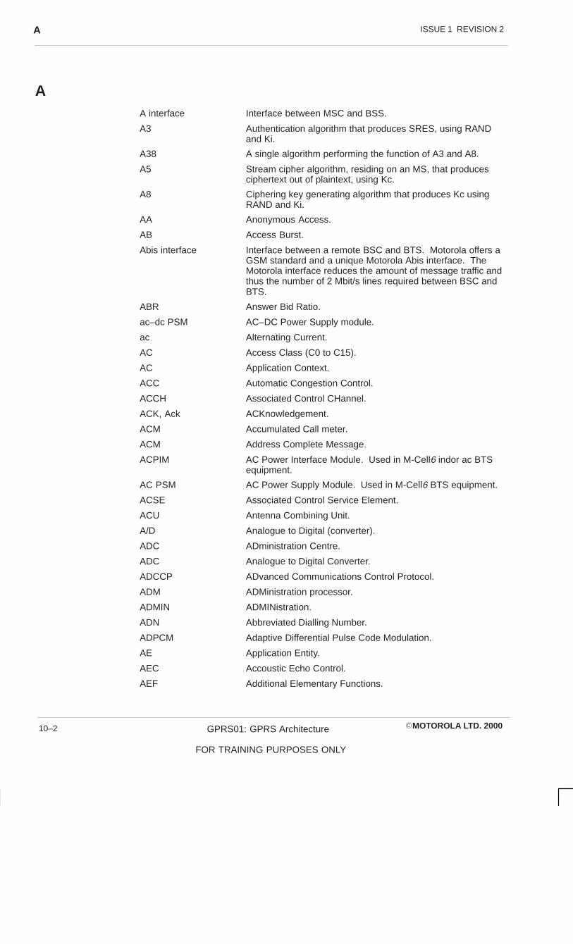
ISSUE 1 REVISION 2A
�MOTOROLA LTD. 2000GPRS01: GPRS Architecture
FOR TRAINING PURPOSES ONLY
10–2
AA interface Interface between MSC and BSS.
A3 Authentication algorithm that produces SRES, using RANDand Ki.
A38 A single algorithm performing the function of A3 and A8.
A5 Stream cipher algorithm, residing on an MS, that producesciphertext out of plaintext, using Kc.
A8 Ciphering key generating algorithm that produces Kc usingRAND and Ki.
AA Anonymous Access.
AB Access Burst.
Abis interface Interface between a remote BSC and BTS. Motorola offers aGSM standard and a unique Motorola Abis interface. TheMotorola interface reduces the amount of message traffic andthus the number of 2 Mbit/s lines required between BSC andBTS.
ABR Answer Bid Ratio.
ac–dc PSM AC–DC Power Supply module.
ac Alternating Current.
AC Access Class (C0 to C15).
AC Application Context.
ACC Automatic Congestion Control.
ACCH Associated Control CHannel.
ACK, Ack ACKnowledgement.
ACM Accumulated Call meter.
ACM Address Complete Message.
ACPIM AC Power Interface Module. Used in M-Cell6 indor ac BTSequipment.
AC PSM AC Power Supply Module. Used in M-Cell6 BTS equipment.
ACSE Associated Control Service Element.
ACU Antenna Combining Unit.
A/D Analogue to Digital (converter).
ADC ADministration Centre.
ADC Analogue to Digital Converter.
ADCCP ADvanced Communications Control Protocol.
ADM ADMinistration processor.
ADMIN ADMINistration.
ADN Abbreviated Dialling Number.
ADPCM Adaptive Differential Pulse Code Modulation.
AE Application Entity.
AEC Accoustic Echo Control.
AEF Additional Elementary Functions.
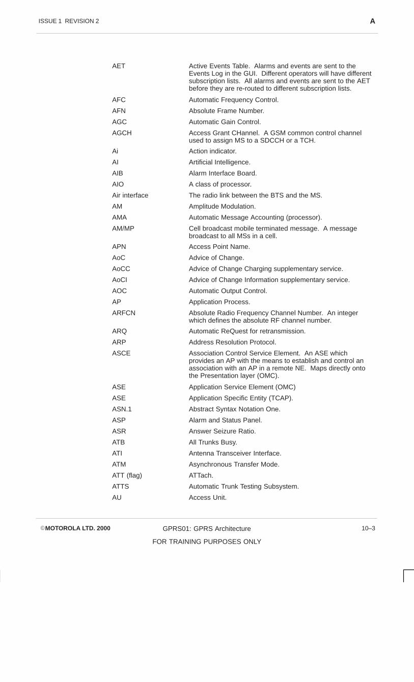
ISSUE 1 REVISION 2 A
�MOTOROLA LTD. 2000 GPRS01: GPRS Architecture
FOR TRAINING PURPOSES ONLY
10–3
AET Active Events Table. Alarms and events are sent to theEvents Log in the GUI. Different operators will have differentsubscription lists. All alarms and events are sent to the AETbefore they are re-routed to different subscription lists.
AFC Automatic Frequency Control.
AFN Absolute Frame Number.
AGC Automatic Gain Control.
AGCH Access Grant CHannel. A GSM common control channelused to assign MS to a SDCCH or a TCH.
Ai Action indicator.
AI Artificial Intelligence.
AIB Alarm Interface Board.
AIO A class of processor.
Air interface The radio link between the BTS and the MS.
AM Amplitude Modulation.
AMA Automatic Message Accounting (processor).
AM/MP Cell broadcast mobile terminated message. A messagebroadcast to all MSs in a cell.
APN Access Point Name.
AoC Advice of Change.
AoCC Advice of Change Charging supplementary service.
AoCI Advice of Change Information supplementary service.
AOC Automatic Output Control.
AP Application Process.
ARFCN Absolute Radio Frequency Channel Number. An integerwhich defines the absolute RF channel number.
ARQ Automatic ReQuest for retransmission.
ARP Address Resolution Protocol.
ASCE Association Control Service Element. An ASE whichprovides an AP with the means to establish and control anassociation with an AP in a remote NE. Maps directly ontothe Presentation layer (OMC).
ASE Application Service Element (OMC)
ASE Application Specific Entity (TCAP).
ASN.1 Abstract Syntax Notation One.
ASP Alarm and Status Panel.
ASR Answer Seizure Ratio.
ATB All Trunks Busy.
ATI Antenna Transceiver Interface.
ATM Asynchronous Transfer Mode.
ATT (flag) ATTach.
ATTS Automatic Trunk Testing Subsystem.
AU Access Unit.

ISSUE 1 REVISION 2A
�MOTOROLA LTD. 2000GPRS01: GPRS Architecture
FOR TRAINING PURPOSES ONLY
10–4
AuC Authentication Centre. A GSM network entity which providesthe functionality for verifying the identity of an MS whenrequested by the system. Often a part of the HLR.
AUT(H) AUThentication.
AUTO AUTOmatic mode.

ISSUE 1 REVISION 2 B
�MOTOROLA LTD. 2000 GPRS01: GPRS Architecture
FOR TRAINING PURPOSES ONLY
10–5
B
B Interface Interface between MSC and VLR.
BA BCCH Allocation. The radio frequency channels allocated in acell for BCCH transmission.
BAIC Barring of All Incoming Calls supplementary service.
BAOC Barring of All Outgoing Calls supplementary service.
BBBX Battery Backup Board.
BBH Base Band Hopping.
BCC BTS Colour Code.
BCCH Broadcast Control CHannel. A GSM control channel used tobroadcast general information about a BTS site on a per cellor sector basis.
BCD Binary Coded Decimal.
BCF Base station Control Function. The GSM term for the digitalcontrol circuitry which controls the BTS. In Motorola cell sitesthis is a normally a BCU which includes DRI modules and islocated in the BTS cabinet.
BCIE Bearer Capability Information Element.
BCU Base station Control Unit. A functional entity of the BSSwhich provides the base control function at a BTS site. Theterm no longer applies to a type of shelf (see BSC and BSU).
BCUP Base Controller Unit Power.
BER Bit Error Rate. A measure of signal quality in the GSMsystem.
BES Business Exchange Services.
BFI Bad Frame Indication.
BG Border Gateway.
BGP Border Gateway Protocol
BHCA Busy Hour Call Attempt.
BI all Barring of All Incoming call supplementary service.
BIB Balanced-line Interconnect Board. Provides interface to 12balanced (6-pair) 120 ohm (37-pin D-type connector) lines for2 Mbit/s circuits (See also T43).
BIC–Roam Barring of All Incoming Calls when Roaming outside theHome PLMN Country supplementary service.
BIM Balanced-line Interconnect Module.
Bin An area in a data array used to store information.
BL BootLoad. Also known as download. For example, databasesand software can be downloaded to the NEs from the BSS.
BLLNG BiLLiNG.
bit/s Bits per second (bps).
Bm Full rate traffic channel.
BN Bit Number. Number which identifies the position of aparticular bit period within a timeslot.

ISSUE 1 REVISION 2B
�MOTOROLA LTD. 2000GPRS01: GPRS Architecture
FOR TRAINING PURPOSES ONLY
10–6
BPF Bandpass Filter.
BPSM �BCU Power Supply Module.
BS Basic Service (group).
BS Bearer Service. A type of telecommunication service thatprovides the capability for the transmission of signalsbetween user-network interfaces. The PLMN connection typeused to support a bearer service may be identical to that usedto support other types of telecommunication service.
BSC Base Station Controller. A network component in the GSMPLMN which has the digital control function of controlling allBTSs. The BSC can be located within a single BTS cabinet(forming a BSS) but is more often located remotely andcontrols several BTSs (see BCF, BCU, and BSU).
BSG Basic Service Group.
BSIC Base Transceiver Station Identity Code. A block of code,consisting of the GSM PLMN colour code and a base stationcolour code. One Base Station can have several BaseStation Colour Codes.
BSIC-NCELL BSIC of an adjacent cell.
BSP Base Site control Processor (at BSC).
BSN Backward Sequence Number.
BSS Base Station System. The system of base station equipment(Transceivers, controllers and so on) which is viewed by theMSC through a single interface as defined by the GSM 08series of recommendations, as being the entity responsiblefor communicating with MSs in a certain area. The radioequipment of a BSS may cover one or more cells. A BSSmay consist of one or more base stations. If an internalinterface is implemented according to the GSM 08.5x seriesof recommendations, then the BSS consists of one BSC andseveral BTSs.
BSSAP BSS Application Part (of Signalling System No. 7) (DTAP +BSSMAP).
BSSC Base Station System Control cabinet. The cabinet whichhouses one or two BSU shelves at a BSC or one or two RXUshelves at a remote transcoder.
BSSGP Base Station System GPRS Protocol.
BSSMAP Base Station System Management Application Part (6-8).
BSSOMAP BSS Operation and Maintenance Application Part (ofSignalling System No. 7).
BSU Base Station Unit shelf. The shelf which houses the digitalcontrol modules for the BTS (p/o BTS cabinet) or BSC (p/oBSSC cabinet).
BT British Telecom.
BT Bus Terminator.
BTC Bus Terminator Card.
BTF Base Transceiver Function.
BTP Base Transceiver Processor (at BTS). One of the six basictask groups within the GPROC.

ISSUE 1 REVISION 2 B
�MOTOROLA LTD. 2000 GPRS01: GPRS Architecture
FOR TRAINING PURPOSES ONLY
10–7
BTS Base Transceiver Station. A network component in the GSMPLMN which serves one cell, and is controlled by a BSC.The BTS contains one or more Transceivers (TRXs).
Burst A period of modulated carrier less than one timeslot. Thephysical content of a timeslot.
BVCI BSSGP Virtual Circuit Identifiers.

ISSUE 1 REVISION 2C
�MOTOROLA LTD. 2000GPRS01: GPRS Architecture
FOR TRAINING PURPOSES ONLY
10–8
CC Conditional.
C Interface Interface between MSC and HLR/AUC.
C7 ITU-TSS Signalling System 7 (sometimes referred to as S7 orSS#7).
CA Cell Allocation. The radio frequency channels allocated to aparticular cell.
CA Central Authority.
CAB Cabinet.
CADM Country ADMinistration. The Motorola procedure used withinDataGen to create new country and network files in theDataGen database.
CAI Charge Advice Information.
CAT Cell Analysis Tool.
CB Cell Broadcast.
CB Circuit Breaker.
CBC Cell Broadcast Centre.
CBCH Cell Broadcast CHannel.
CBF Combining Bandpass Filter.
CBL Cell Broadcast Link.
CBM Circuit Breaker Module.
CBMI Cell Broadcast Message Identifier.
CBSMS Cell Broadcast Short Message Service.
CBUS Clock Bus.
CC Connection Confirm (Part of SCCP network connectivity).
CC Country Code.
CC Call Control.
CCB Cavity Combining Block, a three way RF combiner. Thereare two types of CCB, CCB (Output) and CCB (Extension).These, with up to two CCB Control cards, may comprise theTATI. The second card may be used for redundancy.
CCBS Completion of Calls to Busy Subscriber supplementaryservice.
CCCH Common Control CHannels. A class of GSM controlchannels used to control paging and grant access. IncludesAGCH, PCH, and RACH.
CCCH_GROUP Group of MSs in idle mode.
CCD Common Channel Distributor.
CCDSP Channel Coding Digital Signal Processor.
CCF Conditional Call Forwarding.
CCH Control CHannel. Control channels are channels which carrysystem management messages.
CCH Council for Communications Harmonization (referred to inGSM Recommendations).

ISSUE 1 REVISION 2 C
�MOTOROLA LTD. 2000 GPRS01: GPRS Architecture
FOR TRAINING PURPOSES ONLY
10–9
CCIT Comité Consultatif International Télégraphique etTéléphonique. This term has been superceded by ITU–TSS(International Telecommunications Union –Telecommunications Sector).
CCM Current Call Meter.
CCP Capability/Configuration Parameter.
CCPE Control Channel Protocol Entity.
CCS Hundred call-seconds. The unit in which amounts oftelephone traffic are measured. A single call lasting onehundred seconds is one CCS. See also erlang.
Cct Circuit.
CDB Control Driver Board.
CDE Common Desktop Environment. Part of the SUN software(crontab – cron job file).
CDR Call Detail Records.
CDUR Chargeable DURation.
CEB Control Equalizer Board (BTS).
CED Called station identifier.
CEIR Central Equipment Identity Register.
Cell By GSM definition, a cell is an RF coverage area. At anomni-site, cell is synonymous with site; at a sectored site, cellis synonymous with sector. This differs from analoguesystems where cell is taken to mean the same thing as site.(See below).
Omni Site1-Cell Site
(1 BTS)
6-Sector Siteor
6-Cell Site(6 BTSs)
1 Cell =1 Sector
CEND End of charge point.
CEPT Conférence des administrations Européennes des Postes etTelecommunications.
CERM Circuit Error Rate Monitor.
CF Conversion Facility.
CF all Call Forwarding services.
CFB Call Forwarding on mobile subscriber Busy supplementaryservice.
CFC Conditional Call Forward.
CFNRc Call Forwarding on mobile subscriber Not Reachablesupplementary service.
CFNRy Call Forwarding on No Reply supplementary service.

ISSUE 1 REVISION 2C
�MOTOROLA LTD. 2000GPRS01: GPRS Architecture
FOR TRAINING PURPOSES ONLY
10–10
CFU Call Forwarding Unconditional supplementary service.
Channel A means of one-way transmission. A defined sequence ofperiods (for example, timeslots) in a TDMA system; a definedfrequency band in an FDMA system; a defined sequence ofperiods and frequency bands in a frequency hopped system.
CIM Coaxial Interconnect Module.
CGF Charging Gateway Function.
CHP CHarging Point.
CHV Card Holder Verification information.
CKSN Ciphering Key Sequence Number.
CI Cell Identity. A block of code which identifies a cell within alocation area.
CI CUG Index.
CIC Circuit Identity Code.
CIR, C/I Carrier to Interference Ratio.
Ciphertext Unintelligible data produced through the use of encipherment.
CKSN Ciphering Key Sequence Number.
CLI Calling Line Identity.
CLIP Calling Line Identification Presentation supplementaryservice.
CLIR Calling Line Identification Restriction supplementary service.
CLK Clock.
CLKX Clock Extender half size board. The fibre optic link thatdistributes GCLK to boards in system (p/o BSS etc).
CLM Connectionless Manager.
CLR CLeaR.
CM Configuration Management. An OMC application.
CM Connection Management.
CMD CoMmanD.
CMM Channel Mode Modify.
CMIP Common Management Information Protocol.
CMISE Common Management Information Service Element. An ASEwhich provides a means to transfer management informationvia CMIP messages with another NE over an associationestablished by ASCE using ROSE (OMC).
CMR Cellular Manual Revision.
CNG CalliNg tone.
COLI COnnected Line Identity.
Collocated Placed together; two or more items together in the sameplace.
Coincident Cell A cell which has a co-located neighbour whose cell boundaryfollows the boundary of the said cell. The coincident cell hasa different frequency type, but the same BSIC, as that of theneighbour cell.

ISSUE 1 REVISION 2 C
�MOTOROLA LTD. 2000 GPRS01: GPRS Architecture
FOR TRAINING PURPOSES ONLY
10–11
COLP COnnected Line Identification Presentation supplementaryservice.
COLR COnnected Line Identification Restriction supplementaryservice.
CODEX Manufacturer’s name for a type of multiplexer and packetswitch commonly installed at the Motorola OMC-R.
COM Code Object Manager.
COM COMplete.
COMB Combiner.
CONNACK CONNect ACKnowledgement.
COMM, Comms COMMunications.
CommsLink Communications Link. (2Mbit/s)
CONF CONFerence circuit.
CONFIG CONFIGuration Control Program.
CP Call Processing.
CPU Central Processing Unit.
C/R Command/Response field bit.
CR Carriage Return (RETURN).
CR Connection Request (Part of SCCP network connectivity).
CRC Cyclic Redundancy Check (3 bit).
CRE Call RE-establishment procedure.
CREF Connection REFused (Part of SCCP network connectivity).
CRM Cell Resource Manager.
CRM-LS/HS Cellular Radio Modem-Low Speed/High Speed. Low speedmodem used to interwork 300 to 2400 bit/s data servicesunder V.22bis, V.23, or V.21 standards. High speed modemused to interwork 1200 to 9600 bit/s data services underV.22bis, V.32, or V.29/V.27ter/V.21 standards.
CRT Cathode Ray Tube (video display terminal).
CSFP Code Storage Facility Processor (at BSC and BTS).
CSP Central Statistics Process. The statistics process in the BSC.
CSPDN Circuit Switched Public Data Network.
CT Call Transfer supplementary service.
CT Channel Tester.
CT Channel Type.
CTP Call Trace Product (Tool).
CTR Common Technical Regulation.
CTS Clear to Send. Method of flow control (RS232 Interface).
CTU Compact Transceiver Unit (M-Cellhorizon radio).
CUG Closed User Group supplementary service.
Cumulative value The total value for an entire statistical interval.
CW Call Waiting supplementary service.

ISSUE 1 REVISION 2D
�MOTOROLA LTD. 2000GPRS01: GPRS Architecture
FOR TRAINING PURPOSES ONLY
10–12
D
D Interface Interface between VLR and HLR.
D/A Digital to Analogue (converter).
DAB Disribution Alarm Board.
DAC Digital to Analogue Converter.
DACS Digital Access Cross-connect System.
DAN Digital ANnouncer (for recorded announcements on MSC).
DAS Data Acquisition System.
DAT Digital Audio Tape.
DataGen Sysgen Builder System. A Motorola offline BSS binary objectconfiguration tool.
dB Decibel. A unit of power ratio measurement.
DB DataBase.
DB Dummy Burst (see Dummy burst).
DBA DataBase Administration/Database Administrator.
DBMS DataBase Management System.
dc Direct Current.
DCB Diversity Control Board (p/o DRCU).
DCCH Dedicated Control CHannel. A class of GSM controlchannels used to set up calls and report measurements.Includes SDCCH, FACCH, and SACCH.
DCD Data Carrier Detect signal.
DCE Data Circuit terminating Equipment.
DCF Data Communications Function.
DCF Duplexed Combining bandpass Filter. (Used inHorizonmacro).
DCN Data Communications Network. A DCN connects NetworkElements with internal mediation functions or mediationdevices to the Operations Systems.
DC PSM DC Power Supply Module.
DCS1800 Digital Cellular System at 1800 MHz. A cellular phonenetwork using digital techniques similar to those used in GSM900, but operating on frequencies of 1710 – 1785 MHz and1805 – 1880 MHz.
DDF Dual-stage Duplexed combining Filter. (Used inHorizonmacro).
DDS DataGen Directory Structure.
DDS Data Drive Storage.
DDS Direct Digital Synthesis.
DEQB Diversity Equalizer Board.
DET DETach.
DFE Decision Feedback Equalizer.
DGT Data Gathering Tool.

ISSUE 1 REVISION 2 D
�MOTOROLA LTD. 2000 GPRS01: GPRS Architecture
FOR TRAINING PURPOSES ONLY
10–13
DHCP Dynamic Host Configuration Protocol.
DHP Digital Host Processor.
DIA Drum Intercept Announcer.
DINO E1/HDSL Line termination module.
DINO T1 Line termination module.
DISC DISConnect.
Discon Discontiuous.
DIQ Diversity In phase and Quadrature phase.
DIR Device Interface Routine.
DL Data Link (layer).
DLCI Data Link Connection Identifier.
DLD Data Link Discriminator.
DLNB Diversity Low Noise Block.
DLSP Data Link Service Process.
DLSP Digital Link Signalling Processor.
Dm Control channel (ISDN terminology applied to mobile service).
DMA Deferred Maintenance Alarm. An alarm report level; animmediate or deferred response is required (see also PMA).
DMA Direct Memory Access.
DMR Digital Mobile Radio.
DMX Distributed Electronic Mobile Exchange (Motorola’snetworked EMX family).
DN Directory Number.
DNIC Data network identifier.
DNS Domain Name Server
Downlink Physical link from the BTS towards the MS (BTS transmits,MS receives).
DP Dial/Dialled Pulse.
DPC Destination Point Code. A part of the label in a signallingmessage that uniquely identifies, in a signalling network, the(signalling) destination point of the message.
DPC Digital Processing and Control board.
DPNSS Digital Private Network Signalling System (BT standard forPABX interface).
DPP Dual Path Preselector.
DPR, DPRAM Dual Port Random Access Memory.
DPSM Digital Power Supply Module.
DRAM Dynamic Random Access Memory.
DRC Data Rate Converter board. Provides data and protocolconversion between PLMN and destination network for 8circuits (p/o IWF).
DRCU Diversity Radio Channel Unit. Contains transceiver, digitalcontrol circuits, and power supply (p/o BSS) (see RCU).

ISSUE 1 REVISION 2D
�MOTOROLA LTD. 2000GPRS01: GPRS Architecture
FOR TRAINING PURPOSES ONLY
10–14
(D)RCU Generic term for radio channel unit. May be standard RCU ordiversity radio channel unit DRCU.
DRI Digital Radio Interface. Provides encoding/decoding andencryption/decryption for radio channel (p/o BSS).
DRIM Digital Radio Interface extended Memory. A DRI with extramemory.
DRIX DRI Extender half size board. Fibre optic link from DRI toBCU (p/o BSS).
DRX, DRx Discontinuous reception (mechanism). A means of savingbattery power (for example in hand-portable units) byperiodically and automatically switching the MS receiver onand off.
DS-2 German term for 2 Mbit/s line (PCM interface).
DSE Data Switching Exchange.
DSI Digital Speech Interpolation.
DSP Digital Signal Processor.
DSS1 Digital Subscriber Signalling No 1.
DSSI Diversity Signal Strength Indication.
DTAP Direct Transfer Application Part (6-8).
DTE Data Terminal Equipment.
DTF Digital Trunk Frame.
DT1 DaTa form 1 (Part of SCCP network connectivity).
DTI Digital Trunk Interface.
DTMF Dual Tone Multi-Frequency (tone signalling type).
DTR Data Terminal Ready signal. Method of flow control (RS232Interface).
DTRX Dual Transceiver Module. (Radio used in M-Cellarena andM-Cellarenamacro).
DTX, DTx Discontinuous Transmission (mechanism). A means ofsaving battery power (for example in hand-portable units) andreducing interference by automatically switching thetransmitter off when no speech or data are to be sent.
Dummy burst A period of carrier less than one timeslot whose modulation isa defined sequence that carries no useful information. Adummy burst fills a timeslot with an RF signal when noinformation is to be delivered to a channel.
DYNET DYnamic NETwork. Used to specify BTSs sharing dynamicresources.

ISSUE 1 REVISION 2 E
�MOTOROLA LTD. 2000 GPRS01: GPRS Architecture
FOR TRAINING PURPOSES ONLY
10–15
E
E See Erlang.
E Interface Interface between MSC and MSC.
EA External Alarms.
EAS External Alarm System.
Eb/No Energy per Bit/Noise floor.
EBCG Elementary Basic Service Group.
EC Echo Canceller. Performs echo suppression for all voicecircuits.
ECB Provides echo cancelling for telephone trunks for 30 channels(EC).
ECID The Motorola European Cellular Infrastructure Division.
ECM Error Correction Mode (facsimile).
Ec/No Ratio of energy per modulating bit to the noise spectraldensity.
ECT Event Counting Tool.
ECT Explicit Call Transfer supplementary service.
EEL Electric Echo Loss.
EEPROM Electrically Erasable Programmable Read Only Memory.
EGSM900 Extended GSM900.
EI Events Interface. Part of the OMC-R GUI.
EIR Equipment Identity Register.
EIRP Effective Isotropic Radiated Power.
EIRP Equipment Identity Register Procedure.
EL Echo Loss.
EM Event Management. An OMC application.
EMC ElectroMagnetic Compatibility.
EMF Electro Motive Force.
EMI Electro Magnetic Interference.
eMLPP enhanced Multi-Level Precedence and Pre-emption service.
EMMI Electrical Man Machine Interface.
EMU Exchange office Management Unit (p/o Horizonoffice)
EMX Electronic Mobile Exchange (Motorola’s MSC family).
en bloc Fr. — all at once (a CCITT #7 Digital Transmission scheme);En bloc sending means that digits are sent from one systemto another ~ (that is, all the digits for a given call are sent atthe same time as a group). ~ sending is the opposite ofoverlap sending. A system using ~ sending will wait until ithas collected all the digits for a given call before it attempts tosend digits to the next system. All the digits are then sent asa group.
EOT End of Tape.
EPROM Erasable Programmable Read Only Memory.

ISSUE 1 REVISION 2E
�MOTOROLA LTD. 2000GPRS01: GPRS Architecture
FOR TRAINING PURPOSES ONLY
10–16
EPSM Enhanced Power Supply Module (+27 V).
EQB Equalizer Board. Control circuit for equalization for 8 timeslots each with equalizing circuitry and a DSP (p/o RCU).
EQCP Equalizer Control Processor.
EQ DSP Equalizer Digitizer Signal Processor.
Erlang International (dimensionless) unit of traffic intensity defined asthe ratio of time a facility is occupied to the time it is availablefor occupancy. One erlang is equal to 36 CCS. In the USthis is also known as a traffic unit (TU).
ERP Ear Reference Point.
ERP Effective Radiated Power.
ERR ERRor.
ESP Electro-static Point.
ESQL Embedded SQL (Structured Query Language). An RDBMSprogramming interface language.
E-TACS Extended TACS (analogue cellular system, extended).
Ethernet Type of Local Area Network.
ETR ETSI Technical Report.
ETS European Telecommunication Standard.
ETSI European Telecommunications Standards Institute.
ETX End of Transmission.
EXEC Executive Process.

ISSUE 1 REVISION 2 F
�MOTOROLA LTD. 2000 GPRS01: GPRS Architecture
FOR TRAINING PURPOSES ONLY
10–17
F
F Interface Interface between MSC and EIR.
FA Fax Adaptor.
FA Full Allocation.
FA Functional Area.
FAC Final Assembly Code.
FACCH Fast Associated Control Channel. A GSM dedicated controlchannel which is associated with a TCH and carries controlinformation after a call is set up (see SDCCH).
FACCH/F Fast Associated Control Channel/Full rate.
FACCH/H Fast Associated Control Channel/Half rate.
FB Frequency correction Burst (see Frequency correction burst).
FC-AL Fibre Channel Arbitration Loop. (Type of hard disc).
FCCH Frequency Correction CHannel. A GSM broadcast controlchannel which carries information for frequency correction ofthe mobile (MS).
FCP Fault Collection Process (in BTS).
FCS Frame Check Sequence.
FDM Frequency Division Multiplex.
FDMA Frequency Division Multiple Access.
FDN Fixed Dialling Number.
FDP Fault Diagnostic Procedure.
FEC Forward Error Correction.
FEP Front End Processor.
FER Frame Erasure Ratio.
FFS, FS For Further Study.
FH Frequency Hopping.
FIB Forward Indicator Bit.
FIR Finite Impulse Response (filter type).
FK Foreign Key. A database column attribute; the foreign keyindicates an index into another table.
FM Fault Management (at OMC).
FM Frequency Modulation.
FMIC Fault Management Initiated Clear.
FMUX Fibre optic MUltipleXer.
FN Frame Number. Identifies the position of a particular TDMAframe within a hyperframe.
FOA First Office Application.
FOX Fibre Optic eXtender.
FR Full Rate. Refers to the current capacity of a data channel onthe GSM air interface, that is, 8 simultaneous calls per carrier(see also HR – Half Rate).
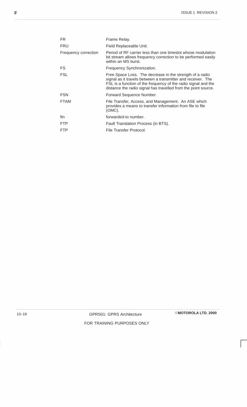
ISSUE 1 REVISION 2F
�MOTOROLA LTD. 2000GPRS01: GPRS Architecture
FOR TRAINING PURPOSES ONLY
10–18
FR Frame Relay.
FRU Field Replaceable Unit.
Frequency correction Period of RF carrier less than one timeslot whose modulationbit stream allows frequency correction to be performed easilywithin an MS burst.
FS Frequency Synchronization.
FSL Free Space Loss. The decrease in the strength of a radiosignal as it travels between a transmitter and receiver. TheFSL is a function of the frequency of the radio signal and thedistance the radio signal has travelled from the point source.
FSN Forward Sequence Number.
FTAM File Transfer, Access, and Management. An ASE whichprovides a means to transfer information from file to file(OMC).
ftn forwarded-to number.
FTP Fault Translation Process (in BTS).
FTP File Transfer Protocol.

ISSUE 1 REVISION 2 G
�MOTOROLA LTD. 2000 GPRS01: GPRS Architecture
FOR TRAINING PURPOSES ONLY
10–19
GG Interface Interface between VLR and VLR.
Gateway MSC An MSC that provides an entry point into the GSM PLMNfrom another network or service. A gateway MSC is also aninterrogating node for incoming PLMN calls.
GB, Gbyte Gigabyte.
GBIC Gigabit Interface Converter.
GCLK Generic Clock board. System clock source, one per site (p/oBSS, BTS, BSC, IWF, RXCDR).
GCR Group Call Register.
GDP Generic DSP Processor board. Interchangeable with the XCDRboard.
GDP E1 GDP board configured for E1 link usage.
GDP T1 GDP board configured for T1 link usage.
GGSN Gateway GPRS Support Node.
GHz Giga-Hertz (109).
GID Group ID. A unique number used by the system to identify auser’s primary group.
GMB GSM Multiplexer Board (p/o BSC).
GMR GSM Manual Revision.
GMSC Gateway Mobile-services Switching Centre (see GatewayMSC).
GMSK Gaussian Minimum Shift Keying. The modulation techniqueused in GSM.
GND GrouND.
GOS Grade of Service.
GPA GSM PLMN Area.
GPC General Protocol Converter.
GPROC Generic Processor board. GSM generic processor board: a68030 with 4 to 16 Mb RAM (p/o BSS, BTS, BSC, IWF,RXCDR).
GPROC2 Generic Processor board. GSM generic processor board: a68040 with 32 Mb RAM (p/o BSS, BTS, BSC, IWF, RXCDR).
GPRS General Packet Radio Service.
GPS Global Positioning by Satellite.
GR GPRS Register.
GSA GSM Service Area. The area in which an MS can be reachedby a fixed subscriber, without the subscriber’s knowledge ofthe location of the MS. A GSA may include the areas servedby several GSM PLMNs.
GSA GSM System Area. The group of GSM PLMN areasaccessible by GSM MSs.
GSM Groupe Spécial Mobile (the committee).
GSM Global System for Mobile communications (the system).

ISSUE 1 REVISION 2G
�MOTOROLA LTD. 2000GPRS01: GPRS Architecture
FOR TRAINING PURPOSES ONLY
10–20
GSM MS GSM Mobile Station.
GSM PLMN GSM Public Land Mobile Network.
GSN GPRS Support Node.
GSR GSM Software Release.
GT Global Title.
GTE Generic Table Editor. The Motorola procedure which allowsusers to display and edit MCDF input files.
GTP GPRS Tunnelling Protocol.
Guard period Period at the beginning and end of timeslot during which MStransmission is attenuated.
GUI Graphical User Interface.
GUI client A computer used to display a GUI from an OMC-R GUIapplication which is beingbrun on a GUI server.
GUI server A computer used to serve the OMC-R GUI applicationprocess running locally (on its processor) to other computers(Gui clients or other MMI processors).
GWY GateWaY (MSC/LR) interface to PSTN.

ISSUE 1 REVISION 2 H
�MOTOROLA LTD. 2000 GPRS01: GPRS Architecture
FOR TRAINING PURPOSES ONLY
10–21
HH Interface Interface between HLR and AUC.
H-M Human-Machine Terminals.
HAD, HAP HLR Authentication Distributor.
HANDO, Handover HANDOver. The action of switching a call in progress fromone radio channel to another radio channel. Handover allowsestablished calls to continue by switching them to anotherradio resource, as when an MS moves from one BTS area toanother. Handovers may take place between the followingGSM entities: timeslot, RF carrier, cell, BTS, BSS and MSC.
HCU Hybrid Combining Unit. (Used in Horizonmacro).
HDLC High level Data Link Control.
HDSL High bit-rate Digital Subscriber Line.
HLC High Layer Compatibility. The HLC can carry informationdefining the higher layer characteristics of a teleservice activeon the terminal.
HLR Home Location Register. The LR where the current locationand all subscriber parameters of an MS are permanentlystored.
HMS Heat Management System. The system that providesenvironmental control of the components inside the ExCell,TopCell and M-Cell cabinets.
HO HandOver. (see HANDO above).
HPU Hand Portable Unit.
HOLD Call hold supplementary service.
HPLMN Home PLMN.
HR Half Rate. Refers to a type of data channel that will doublethe current GSM air interface capacity to 16 simultaneouscalls per carrier (see also FR – Full Rate).
HS HandSet.
HSI/S High Speed Interface card.
HSM HLR Subscriber Management.
HSN Hopping Sequence Number.
HU Home Units.
HW Hardware.
Hyperframe 2048 superframes. The longest recurrent time period of theframe structure.

ISSUE 1 REVISION 2I
�MOTOROLA LTD. 2000GPRS01: GPRS Architecture
FOR TRAINING PURPOSES ONLY
10–22
I
I Information frames (RLP).
IA Incomming Access (closed user group (CUG) SS(supplementary service)).
IA5 International Alphanumeric 5.
IADU Integrated Antenna Distribution Unit. (The IADU is theequivalent of the Receive Matrix used on pre-M-Cell BTSs).
IAM Initial Address Message.
IAS Internal Alarm System.
IC Integrated Circuit.
IC Interlock Code (CUG SS).
IC(pref) Interlock Code op the preferential CUG.
ICB Incoming Calls Barred.
ICC Integrated Circuit(s) Card.
ICM In-Call Modification.
ICMP Internet Control Message Protocol.
ID, Id IDentification/IDentity/IDentifier.
IDN Integrated Digital Network.
IDS INFOMIX Database Server. (OMC-R relational databasemanagement system).
IE Information Element (signalling).
IEC International Electrotechnical Commission.
IEEE Institute of Electrical and Electronic Engineers.
IEI Information Element Identifier.
I-ETS Interim European Telecommunication Standard.
IF Intermediate Frequency.
IFAM Initial and Final Address Message.
IM InterModulation.
IMACS Intelligent Monitor And Control System.
IMEI International Mobile station Equipment Identity. Electronicserial number that uniquely identifies the MS as a piece orassembly of equipment. The IMEI is sent by the MS alongwith request for service.
IMM IMMediate assignment message.
IMSI International Mobile Subscriber Identity. Published mobilenumber (prior to ISDN) (see also MSISDN) that uniquelyidentifies the subscription. It can serve as a key to derivesubscriber information such as directory number(s) from theHLR.
IN Intelligent Network.
IN Interrogating Node. A switching node that interrogates anHLR, to route a call for an MS to the visited MSC.
INS IN Service.

ISSUE 1 REVISION 2 I
�MOTOROLA LTD. 2000 GPRS01: GPRS Architecture
FOR TRAINING PURPOSES ONLY
10–23
INS Intelligent Network Service.
InterAlg Interference Algorithm. A single interference algorithm in acell.
Interworking The general term used to describe the inter-operation ofnetworks, services, supplementary services and so on. Seealso IWF.
Interval A recording period of time in which a statistic is pegged.
Interval expiry The end of an interval.
I/O Input/Output.
IOS Intelligent Optimization Platform.
IP Initialisation Process.
IP Internet Protocol.
IPC Inter-Process Communication.
IP, INP INtermodulation Products.
IPR Intellectual PRoperty.
IPSM Integrated Power Supply Module (–48 V).
IPV4 Internet Protocol Version 4.
IPV6 Internet Protocol Version 6.
IPX (A hardware component).
ISAM Indexed Sequential Access Method.
ISC International Switching Centre.
ISDN Integrated Services Digital Network. An integrated servicesnetwork that provides digital connections betweenuser-network interfaces.
ISG Motorola Information Systems group (formally CODEX).
ISO International Organisation for Standardization.
ISQL Informix Structured Query Language.
ISS IP Support Server.
ISUP ISDN User Part (of signalling system No. 7).
IT Inactivity Test (Part of SCCP network connectivity).
ITC Information Transfer Capability.
ITU International Telecommunication Union.
ITU–TSS International Telecommunication Union – TelecommunicationsSector.
IWF InterWorking Function. A network functional entity whichprovides network interworking, service interworking,supplementary service interworking or signalling interworking.It may be a part of one or more logical or physical entities in aGSM PLMN.
IWMSC InterWorking MSC.
IWU InterWorking Unit.

ISSUE 1 REVISION 2K
�MOTOROLA LTD. 2000GPRS01: GPRS Architecture
FOR TRAINING PURPOSES ONLY
10–24
Kk kilo (103).
k Windows size.
K Constraint length of the convolutional code.
KAIO Kernal Asynchronous Input/Output.
kb, kbit kilo-bit.
kbit/s, kbps kilo-bits per second.
kbyte kilobyte.
Kc Ciphering key. A sequence of symbols that controls theoperation of encipherment and decipherment.
kHz kilo-Hertz (103).
Ki Individual subscriber authentication Key (p/o authenticationprocess of AUC).
KIO A class of processor.
KSW Kiloport SWitch board. TDM timeslot interchanger to connectcalls (p/o BSS).
KSWX KSW Expander half size board. Fibre optic distribution ofTDM bus (p/o BSS).
kW kilo-Watt.

ISSUE 1 REVISION 2 L
�MOTOROLA LTD. 2000 GPRS01: GPRS Architecture
FOR TRAINING PURPOSES ONLY
10–25
L
L1 Layer 1.
L2ML Layer 2 Management Link.
L2R Layer 2 Relay function. A function of an MS and IWF thatadapts a user’s known layer2 protocol LAPB onto RLP fortransmission between the MT and IWF.
L2R BOP L2R Bit Orientated Protocol.
L2R COP L2R Character Orientated Protocol.
L3 Layer 3.
L3MM Layer 3 Mobility Management.
LA Location Area. An area in which an MS may move freelywithout updating the location register. An LA may compriseone or several base station areas.
LAC Location Area Code.
LAI Location Area Identity. The information indicating the locationarea in which a cell is located.
LAN Local Area Network.
LANX LAN Extender half size board. Fibre optic distribution of LANto/from other cabinets (p/o BSS etc).
LAPB Link Access Protocol Balanced (of ITU–TSS Rec. x.25).
LAPD Link Access Protocol Data.
LAPDm Link Access Protocol on the Dm channel.
LC Inductor Capacitor (type of filter).
LCF Link Control Function.
LCN Local Communications Network.
LCP Link Control Processor.
LE Local Exchange.
LED Light Emitting Diode.
LF Line Feed.
LI Length Indicator.
LI Line Identity.
LLC Lower Layer Compatibility. The LLC can carry informationdefining the lower layer characteristics of the terminal.
LLC Logical Link Control.
LLC PDU LLC Protocol Data Unit.
Lm Traffic channel with capacity lower than a Bm.
LMP LAN Monitor Process.
LMS Least Mean Square.
LMSI Local Mobile Station Identity. A unique identity temporarilyallocated to visiting mobile subscribers in order to speed upthe search for subscriber data in the VLR, when the MSRNallocation is done on a per cell basis.
LMT Local Maintenance Terminal.

ISSUE 1 REVISION 2L
�MOTOROLA LTD. 2000GPRS01: GPRS Architecture
FOR TRAINING PURPOSES ONLY
10–26
LNA Low Noise Amplifier.
LND Last Number Dialled.
Location area An area in which a mobile station may move freely withoutupdating the location register. A location area may compriseone or several base station areas.
LPC Linear Predictive Code.
LPLMN Local PLMN.
LR Location Register. The GSM functional unit where MSlocation information is stored. The HLR and VLR are locationregisters.
LSSU Link Stations Signalling Unit (Part of MTP transport system).
LSTR Listener Side Tone Rating.
LTA Long Term Average. The value required in a BTS’s GCLKfrequency register to produce a 16.384 MHz clock.
LTE Local Terminal Emulator.
LTP Long Term Predictive.
LTU Line Terminating Unit.
LU Local Units.
LU Location Update.
LV Length and Value.

ISSUE 1 REVISION 2 M
�MOTOROLA LTD. 2000 GPRS01: GPRS Architecture
FOR TRAINING PURPOSES ONLY
10–27
MM Mandatory.
M Mega (106).
M-Cell Motorola Cell.
M&TS Maintenance and Troubleshooting. Functional area ofNetwork Management software which (1) collects anddisplays alarms, (2) collects and displays Software/Hardwareerrors, and (3) activates test diagnostics at the NEs (OMC).
MA Mobile Allocation. The radio frequency channels allocated toan MS for use in its frequency hopping sequence.
MAC Medium Access Control.
MACN Mobile Allocation Channel Number.
Macrocell A cell in which the base station antenna is generally mountedaway from buildings or above rooftop level.
MAF Mobile Additional Function.
MAH Mobile Access Hunting supplementary service.
MAI Mobile Allocation Index.
MAIDT Mean Accumulated Intrinsic Down Time.
MAINT MAINTenance.
MAIO Mobile Allocation Index Offset.
MAP Mobile Application Part (of signalling system No. 7). Theinter-networking signalling between MSCs and LRs and EIRs.
MAPP Mobile Application Part Processor.
MB, Mbyte Megabyte.
Mbit/s Megabits per second.
MCAP Motorola Cellular Advanced Processor.
MCC Mobile Country Code.
MCDF Motorola Customer Data Format used by DataGen for simpledata entry and retrieval.
MCI Malicious Call Identification supplementary service.
MCSC Motorola Customer Support Centre.
MCU Main Control Unit for M-Cell2/6. Also referred to as the MicroControl Unit in software.
MCUF Main Control Unit, with dual FMUX. (Used in M-Cellhorizon).
MCU-m Main Control Unit for M-Cell Micro sites (M-Cellm). Alsoreferred to as the Micro Control Unit in software.
MCUm The software subtype representation of the Field ReplaceableUnit (FRU) for the MCU-m.
MD Mediation Device.
MDG Mobile Detached Flag for GPRS.
MDL (mobile) Management (entity) - Data Link (layer).
ME Maintenance Entity (GSM Rec. 12.00).

ISSUE 1 REVISION 2M
�MOTOROLA LTD. 2000GPRS01: GPRS Architecture
FOR TRAINING PURPOSES ONLY
10–28
ME Mobile Equipment. Equipment intended to access a set ofGSM PLMN and/or DCS telecommunication services, butwhich does not contain subscriber related information.Services may be accessed while the equipment, capable ofsurface movement within the GSM system area, is in motionor during halts at unspecified points.
MEF Maintenance Entity Function (GSM Rec. 12.00).
MF MultiFrame.
MF Multi-Frequency (tone signalling type).
MF MultiFunction block.
MGMT, mgmt Management.
MGR Manager.
MHS Message Handling System.
MHS Mobile Handling Service.
MHz Mega-Hertz (106).
MI Maintenance Information.
MIB Management Information Base. A Motorola OMC-Rdatabase. There is a CM MIB and an EM MIB.
MIC Mobile Interface Controller.
Microcell A cell in which the base station antenna is generally mountedbelow rooftop level. Radio wave propagation is by diffractionand scattering around buildings, the main propagation iswithin street canyons.
min minute(s).
�s micro-second (10–6).
�BCU Micro Base Control Unit.
MIT Management Information Tree. Name of a file on theMotorola OMC-R.
MM Man Machine.
MM Mobility Management.
MME Mobile Management Entity.
MMF Middle Man Funnel process.
MMI Man Machine Interface. The method in which the userinterfaces with the software to request a function or changeparameters.
MMI client A machine configured to use the OMC-R software from anMMI server.
MMI processor MMI client/MMI server.
MMI server A computer which has its own local copy of the OMC-Rsoftware. It can run the OMC-R software for MMI clients tomount.
MML Man Machine Language. The tool of MMI.
MMS Multiple Serial Interface Link. (see also 2Mbit/s link)
MNC Mobile Network Code.
MNR Mobile Not Reachable Flag.

ISSUE 1 REVISION 2 M
�MOTOROLA LTD. 2000 GPRS01: GPRS Architecture
FOR TRAINING PURPOSES ONLY
10–29
MNT MaiNTenance.
MO Mobile Originated.
MO/PP Mobile Originated Point-to-Point messages.
MOMAP Motorola OMAP.
MoU Memorandum of Understanding.
MPC Multi Personal Computer (was p/o OMC).
MPH (mobile) Management (entity) - PHysical (layer) [primitive].
MPTY MultiParTY (Multi ParTY) supplementary service.
MPX MultiPleXed.
MRC Micro Radio Control Unit.
MRN Mobile Roaming Number.
MRP Mouth Reference Point.
MS Mobile Station. The GSM subscriber unit.
MSC Mobile-services Switching Centre, Mobile Switching Centre.
MSCM Mobile Station Class Mark.
MSCU Mobile Station Control Unit.
msec millisecond (.001 second).
MSI Multiple Serial Interface board. Intelligent interface to two2 Mbit/s digital links (see 2 Mbit/s link and DS-2) (p/o BSS).
MSIN Mobile Station Identification Number.
MSISDN Mobile Station International ISDN Number. Published mobilenumber (see also IMSI). Uniquely defines the mobile stationas an ISDN terminal. It consists of three parts: the CountryCode (CC), the National Destination Code (NDC) and theSubscriber Number (SN).
MSP Multiple Subscriber Profile.
MSRN Mobile Station Roaming Number. A number assigned by theMSC to service and track a visiting subscriber.
MSU Message Signal Unit (Part of MTP transport system). Asignal unit containing a service information octet and asignalling information field which is retransmitted by thesignalling link control, if it is received in error.
MT Mobile Terminated. Describes a call or short messagedestined for an MS.
MT (0, 1, 2) Mobile Termination. The part of the MS which terminates theradio transmission to and from the network and adaptsterminal equipment (TE) capabilities to those of the radiotransmission. MT0 is mobile termination with no support forterminal, MT1 is mobile termination with support for an S-typeinterface and MT2 is mobile termination with support for anR-type interface.
MTBF Mean Time Between Failure.
MTM Mobile-To-Mobile (call).
MTP Message Transfer Part.
MT/PP Mobile Terminated Point-to-Point messages.
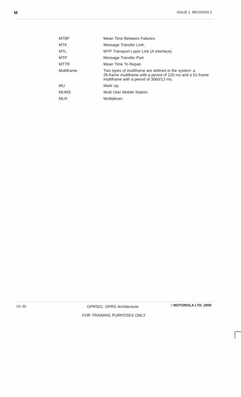
ISSUE 1 REVISION 2M
�MOTOROLA LTD. 2000GPRS01: GPRS Architecture
FOR TRAINING PURPOSES ONLY
10–30
MTBF Mean Time Between Failures.
MTK Message Transfer LinK.
MTL MTP Transport Layer Link (A interface).
MTP Message Transfer Part.
MTTR Mean Time To Repair.
Multiframe Two types of multiframe are defined in the system: a26-frame multiframe with a period of 120 ms and a 51-framemultiframe with a period of 3060/13 ms.
MU Mark Up.
MUMS Multi User Mobile Station.
MUX Multiplexer.

ISSUE 1 REVISION 2 N
�MOTOROLA LTD. 2000 GPRS01: GPRS Architecture
FOR TRAINING PURPOSES ONLY
10–31
NNAT Network Address Translation.
N/W Network.
NB Normal Burst (see Normal burst).
NBIN A parameter in the hoping sequence.
NCC Network (PLMN) Colour Code.
NCELL Neighbouring (of current serving) Cell.
NCH Notification CHannel.
ND No Duplicates. A database column attribute meaning thecolumn contains unique values (used only with indexedcolumns).
NDC National Destination Code.
NDUB Network Determined User Busy.
NE Network Element (Network Entity).
NEF Network Element Function block.
NET Norme Européennes de Telecommunications.
NETPlan Frequency planning tool.
NF Network Function.
NFS Network File System.
NHA Network Health Analyst. Optional OMC-R processor feature.
NIC Network Interface Card.
NIC Network Independent Clocking.
NIS Network Information Service. It allows centralised control ofnetwork information for example hostnames, IP addressesand passwords.
NIU Network Interface Unit.
NIU-m Network Interface Unit, micro.
NLK Network LinK processor(s).
Nm Newton metres.
NM Network Management (manager). NM is all activities whichcontrol, monitor and record the use and the performance ofresources of a telecommunications network in order toprovide telecommunication services to customers/users at acertain level of quality.
NMASE Network Management Application Service Element.
NMC Network Management Centre. The NMC node of the GSMTMN provides global and centralised GSM PLMN monitoringand control, by being at the top of the TMN hierarchy andlinked to subordinate OMC nodes.
NMSI National Mobile Station Identification number.
NMT Nordic Mobile Telephone system.
NN No Nulls. A database column attribute meaning the columnmust contain a value in all rows.
Normal burst A period of modulated carrier less than a timeslot.

ISSUE 1 REVISION 2N
�MOTOROLA LTD. 2000GPRS01: GPRS Architecture
FOR TRAINING PURPOSES ONLY
10–32
NPI Number Plan Identifier.
NRZ Non Return to Zero.
NSAP Network Service Access Point.
NSAPI Network Layer Service Access Point Identifier.
NSP Network Service Provider.
NSS Network Status Summary.
NT Network Termination.
NT Non Transparent.
NTAAB New Type Approval Advisory Board.
NTP Network Time Protocol.
NUA Network User Access.
NUI Network User Identification.
NUP National User Part (of signalling system No. 7).
NV NonVolatile.
NVRAM Non-Volatile Random Access Memory.
nW Nano-Watt (10–9).
ISSUE 1 REVISION 2 O
�MOTOROLA LTD. 2000 GPRS01: GPRS Architecture
FOR TRAINING PURPOSES ONLY
10–33
O
O Optional.
OA Outgoing Access (CUG SS).
O&M Operations and Maintenance.
OASCU Off-Air-Call-Set-Up. The procedure in which atelecommunication connection is being established whilst theRF link between the MS and the BTS is not occupied.
OCB Outgoing Calls Barred within the CUG.
OCXO Oversized Voltage Controlled Crystal Oscillator.
OD Optional for operators to implement for their aim.
OFL % OverFlow.
offline IDS shutdown state.
online IDS normal operatng state.
OIC Operator Initiated Clear.
OLM Off_Line MIB. A Motorola DataGen database, used to modifyand carry out Radio Frequency planning on multiple BSSbinary files.
OLR Overall Loudness Rating.
OMAP Operations and Maintenance Application Part (of signallingsystem No. 7) (was OAMP).
OMC Operations and Maintenance Centre. The OMC node of theGSM TMN provides dynamic O&M monitoring and control ofthe PLMN nodes operating in the geographical areacontrolled by the specific OMC.
OMC-G Operations and Maintenance Centre — Gateway Part.(Iridium)
OMC-G Operations and Maintenance Centre — GPRS Part.
OMC-R Operations and Maintenance Centre — Radio Part.
OMC-S Operations and Maintenance Centre — Switch Part.
OMF Operations and Maintenance Function (at BSC).
OML Operations and Maintenance Link.
OMP Operation and Maintenance Processor.
OMS Operation and Maintenance System (BSC–OMC).
OMSS Operation and Maintenance SubSystem.
OOS Out Of Service.
OPC Originating Point Code. A part of the label in a signallingmessage that uniquely identifies, in a signalling network, the(signalling) origination point of the message.
ORAC Olympus Radio Architecture Chipset.
OS Operating System.
OSI Open Systems Interconnection.
OSI RM OSI Reference Model.
OSF Operation Systems Function block.

ISSUE 1 REVISION 2O
�MOTOROLA LTD. 2000GPRS01: GPRS Architecture
FOR TRAINING PURPOSES ONLY
10–34
OSF/MOTIF Open Software Foundation Motif. The basis of the GUI usedfor the Motorola OMC-R MMI.
OSS Operator Services System.
Overlap Overlap sending means that digits are sent from one systemto another as soon as they are received by the sendingsystem. A system using ~ will not wait until it has received alldigits of a call before it starts to send the digits to the nextsystem. This is the opposite of en bloc sending where alldigits for a given call are sent at one time.

ISSUE 1 REVISION 2 P
�MOTOROLA LTD. 2000 GPRS01: GPRS Architecture
FOR TRAINING PURPOSES ONLY
10–35
PPA Power Amplifier.
PAB Power Alarm Board.
PABX Private Automatic Branch eXchange.
PACCH Packet Associated Control Channel
PAD Packet Assembler/Disassembler facility.
Paging The procedure by which a GSM PLMN fixed infrastructureattempts to reach an MS within its location area, before anyother network-initiated procedure can take place.
PATH CEPT 2 Mbit/s route through the BSS network.
PBUS Processor Bus.
PBX Private Branch eXchange.
PC Personal Computer.
PCH Paging CHannel. A GSM common control channel used tosend paging messages to the MSs.
PCHN Paging Channel Network.
PCHN Physical Channel.
PCM Pulse Code Modulation (see also 2 Mbit/s link which is thephysical bearer of PCM).
PCN Personal Communications Network.
PCR Preventative Cyclic Retransmission. A form of errorcorrection suitable for use on links with long transmissiondelays, such as satellite links.
PCU Packet Control Unit (p/o GPRS).
PCU Picocell Control unit (p/o M-Cellaccess).
pd Potential difference.
PD Protocol Discriminator.
PD Public Data.
PDB Power Distribution Board.
PDCH Packet Data Channel.
PDF Power Distribution Frame (MSC/LR).
PDN Public Data Networks.
PDN Packet Data Network.
PDTCH Packet Data traffic Channel.
PDU Power Distribution Unit.
PDU Protected Data Unit.
PDU Protocol Data Unit.
PEDC Pan European Digital Cellular.
Peg A single incremental action modifying the value of a statistic.
Pegging Modifying a statistical value.
PH Packet Handler.
PH PHysical (layer).

ISSUE 1 REVISION 2P
�MOTOROLA LTD. 2000GPRS01: GPRS Architecture
FOR TRAINING PURPOSES ONLY
10–36
PHI Packet Handler Interface.
PI Presentation Indicator.
Picocell A cell site where the base station antenna is mounted within abuilding.
PICS Protocol Implementation Conformance Statement.
PID Process IDentifier/Process ID.
PIM PCM Interface Module (MSC).
PIN Personal Identification Number.
PIN Problem Identification Number.
PIX Parallel Interface Extender half size board. Customer alarminterface (p/o BSS).
PIXT Protocol Implementation eXtra information for Testing.
PK Primary Key. A database column attribute, the primary key isa not-null, non-duplicate index.
Plaintext Unciphered data.
PlaNET Frequency planning tool.
PLL Phase Lock Loop (refers to phase locking the GCLK in theBTS).
PLMN Public Land Mobile Network. The mobile communicationsnetwork.
PM Performance Management. An OMC application.
PM-UI Performance Management User Interface.
PMA Prompt Maintenance Alarm. An alarm report level; immediateaction is necessary (see also DMA).
PMS Pseudo MMS.
PMUX PCM MUltipleXer.
PN Permanent Nucleus (of GSM).
PNE Présentation des Normes Européennes.
POI Point of Interconnection (with PSTN).
POTS Plain Old Telephone Service (basic telephone services).
p/o Part of.
pp, p-p Peak-to-peak.
PP Point-to-Point.
ppb Parts per billion.
PPE Primative Procedure Entity.
ppm Parts per million (x 10–6).
PPP Point to Point Protocol.
Pref CUG Preferential CUG.
Primary Cell A cell which is already optimized in the network and has aco-located neighbour whose cell boundary follows theboundary of the said cell. The primary cell has a preferredband equal to the frequency type of the coincident cell.
PROM Programmable Read Only Memory.

ISSUE 1 REVISION 2 P
�MOTOROLA LTD. 2000 GPRS01: GPRS Architecture
FOR TRAINING PURPOSES ONLY
10–37
Ps Location probability.
PSA Periodic Supervision of Accessability.
PSAP Presentation Services Access Point.
PSM Power Supply Module.
PSPDN Packet Switched Public Data Network. Public datacommunications network. x.25 links required for NE to OMCcommunications will probably be carried by PSPDN.
PSTN Public Switched Telephone Network. The UK land linetelephone network.
PSU Power Supply Unit.
PSW Pure Sine Wave.
PTM Point to Multipoint
PTM-G Point to Multipoint for Group.
PTM-M Point to Multipoint for Multicast.
PTO Public Telecommunications Operator.
PTP Point to Point.
PTP-CLNS Point to Point Connectionless Service.
PVC-CONS Point to Point Connection Oriented Service.
PUCT Price per Unit Currency Table.
PVC Permanent Virtual Circuit.
PW Pass Word.
PWR Power.
PXPDN Private eXchange Public Data Network.

ISSUE 1 REVISION 2Q
�MOTOROLA LTD. 2000GPRS01: GPRS Architecture
FOR TRAINING PURPOSES ONLY
10–38
QQA Q (Interface) – Adapter.
Q3 Interface between NMC and GSM network.
Q-adapter Used to connect MEs and SEs to TMN (GSM Rec. 12.00).
QAF Q-Adapter Function.
QEI Quad European Interface. Interfaces four 2 Mbit/s circuits toTDM switch highway (see MSI).
QIC Quarter Inch Cartridge (Data storage format).
QOS Quality Of Service.
Quiescent mode IDS intermediate state before shutdown.

ISSUE 1 REVISION 2 R
�MOTOROLA LTD. 2000 GPRS01: GPRS Architecture
FOR TRAINING PURPOSES ONLY
10–39
RR Value of reduction of the MS transmitted RF power relative to
the maximum allowed output power of the highest powerclass of MS (A).
RA RAndom mode request information field.
RA Routing Area.
RAB Random Access Burst.
RAC Routing Area Code.
RACCH Random Access Control CHannel. A GSM common controlchannel used to originate a call or respond to a page.
RACH Random Access CHannel.
RAI Routing Area Identity.
RAM Random Access Memory.
RAND RANDom number (used for authentication).
RATI Receive Antenna Transceiver Interface.
RAx Rate Adaptation.
RBDS Remote BSS Diagnostic System (a discontinued Motoroladiagnostic facility).
RBER Residual Bit Error Ratio.
RBTS Remote Base Transceiver Station.
RCB Radio Control Board (p/o DRCU).
RCI Radio Channel Identifier.
RCP Radio Control Processor.
RCU Radio Channel Unit. Contains transceiver, digital controlcircuits, and power supply (p/o BSS) (see DRCU).
RCVR Receiver.
RDBMS Relational DataBase Management System (INFORMIX).
RDI Radio Digital Interface System.
RDIS Restricted Digital Information.
RDM Reference Distribution Module.
RDN Relative Distinguished Name. A series of RDN form a uniqueidentifier, the distinguished name, for a particular networkelement.
REC, Rec RECommendation.
REJ REJect(ion).
REL RELease.
RELP Residual Excited Linear Predictive.
RELP-LTP RELP Long Term Prediction. A name for GSM full rate (seefull rate).
resync Resynchronize/resynchronization.
REQ REQuest.
Revgen A Motorola DataGen utility for producing an MMI script from abinary object database.

ISSUE 1 REVISION 2R
�MOTOROLA LTD. 2000GPRS01: GPRS Architecture
FOR TRAINING PURPOSES ONLY
10–40
RF Radio Frequency.
RFC, RFCH Radio Frequency Channel. A partition of the system RFspectrum allocation with a defined bandwidth and centrefrequency.
RFE Receiver Front End (shelf).
RFEB Receiver Front End Board (p/o DRCU II).
RFI Radio Frequency Interference.
RFM Radio Frequency Module.
RFN Reduced TDMA Frame Number.
RFU Reserved for Future Use.
RJ45 Network cable/Connector type.
RISC Reduced Instruction Set Computer.
RL Remote login.
RLC Release Complete.
PLC Radio Link Control.
RLP Radio Link Protocol. An ARQ protocol used to transfer userdata between an MT and IWF. See GSM 04.22.
RLR Receiver Loudness Rating.
RLSD ReLeaSeD.
RMS Root Mean Square (value).
RMSU Remote Mobile Switching Unit.
RNTABLE Table of 128 integers in the hopping sequence.
ROM Read Only Memory.
ROSE Remote Operations Service Element. An ASE which carriesa message between devices over an association establishedby ASCE (a CCITT specification for O & M) (OMC).
Roundtrip Time period between transmit and receive instant of atimeslot in the BTS, propagation determined by the responsebehaviour of the MS and the MS to BTS delay distance.
RPE Regular Pulse Excited.
RPE-LTP Regular Pulse Excitation - Long Term Prediction. The GSMdigital speech coding scheme.
RPOA Recognised Private Operating Agency.
RPR Read Privilege Required. Access to the column is allowedonly for privileged accounts.
RR Radio Resource management.
RR Receive Ready (frame).
RRSM Radio Resource State Machine.
RS232 Standard serial interface.
RSE Radio System Entity.
RSL Radio Signalling Link.
RSLF Radio System Link Function.
RSLP Radio System Link Processor.

ISSUE 1 REVISION 2 R
�MOTOROLA LTD. 2000 GPRS01: GPRS Architecture
FOR TRAINING PURPOSES ONLY
10–41
RSS Radio SubSystem (replaced by BSS).
RSSI Received Signal Strength Indicator.
RSZI Regional Subscription Zone Identity.
RTC Remotely Tuneable Channel Combiner.
RTE Remote Terminal Emulator.
RTF Radio Transceiver Function.
RTF Receive Transmit Functions.
RTS Request to Send. Method of flow control (RS232 Interface).
RU Rack Unit.
Run level System processor operating mode.
Rx Receive(r).
RXCDR Remote Transcoder.
RXF Receive Function (of the RTF).
RXLEV-D Received signal level downlink.
RXLEV-U Received signal level uplink.
RXQUAL-D Received signal quality downlink.
RXQUAL-U Received signal quality uplink.
RXU Remote Transcoder Unit. The shelf which houses theremote transcoder modules in a BSSC cabinet at a remotetranscoder site.

ISSUE 1 REVISION 2S
�MOTOROLA LTD. 2000GPRS01: GPRS Architecture
FOR TRAINING PURPOSES ONLY
10–42
SS/W SoftWare.
SABM Set Asynchronous Balanced Mode. A message whichestablishes the signalling link over the air interface.
SABME SABM Extended.
SACCH Slow Associated Control CHannel. A GSM control channelused by the MS for reporting RSSI and signal qualitymeasurements.
SACCH/C4 Slow Associated Control CHannel/SDCCH/4.
SACCH/C8 Slow Associated Control CHannel/SDCCH/8.
SACCH/T Slow Associated Control CHannel/Traffic channel.
SACCH/TF Slow Associated Control CHannel/Traffic channel Full rate.
SACCH/TH Slow Associated Control CHannel/Traffic channel Half rate.
SAGE A brand of trunk test equipment.
SAP Service Access Point. In the reference model for OSI, SAPsof a layer are defined as gates through which services areoffered to an adjacent higher layer.
SAP System Audits Process.
SAPI Service Access Point Indicator (identifier).
SAW Surface Acoustic Wave.
SB Synchronization Burst (see Synchronization burst).
SBUS Serial Bus.
SC Service Centre (used for Short Message Service).
SC Service Code.
SCCA System Change Control Administration. Software modulewhich allows full or partial software download to the NE(OMC).
SCCP Signalling Connection Control Part (6-8).
SCEG Speech Coding Experts Group (of GSM).
SCH Synchronization CHannel. A GSM broadcast control channelused to carry information for frame synchronization of MSsand identification of base stations.
SCI Status Control Interface.
SCIP Serial Communication Interface Processor.
SCM Status Control Manager.
SCN Sub-Channel Number. One of the parameters defining aparticular physical channel in a BS.
SCP Service Control Point (an intelligent network entity).
SCSI Small Computer Systems Interface.
SCU Slim Channel Unit.
SCU900 Slim Channel Unit for GSM900.
SDCCH Stand-alone Dedicated Control CHannel. A GSM controlchannel where the majority of call setup occurs. Used forMS to BTS communications before MS assigned to TCH.

ISSUE 1 REVISION 2 S
�MOTOROLA LTD. 2000 GPRS01: GPRS Architecture
FOR TRAINING PURPOSES ONLY
10–43
SDL Specification Description Language.
SDT SDL Developement Tool.
SDU Service Data Unit.
SDR Special Drawing Rights (an international “basket” currency forbilling).
SE Support Entity (GSM Rec. 12.00).
Secondary Cell A cell which is not optimized in the network and has aco-located neighbour whose cell boundary follows theboundary of the said cell. The secondary cell has a preferredband the same as that of its own frequency type.
SEF Support Entity Function (GSM Rec.12.00).
SFH Slow Frequency Hopping.
SI Screening Indicator.
SI Service Interworking.
SI Supplementary Information.
SIA Supplementary Information A.
SID Silence Descriptor.
SIF Signal Information Field. The bits of a message signal unitthat carry information for a certain user transaction; the SIFalways contains a label.
SIM Subscriber Identity Module. Removable module which isinserted into a mobile equipment; it is considered as part ofthe MS. It contains security related information (IMSI, Ki,PIN), other subscriber related information and the algorithmsA3 and A8.
SIMM Single Inline Memory module.
SIMM System Integrated Memory Module.
SIO Service Information Octet. Eight bits contained in a messagesignal unit, comprising the service indicator and sub-servicefield.
SITE BSC, BTS or collocated BSC-BTS site.
SIX Serial Interface eXtender. Converts interface levels to TTLlevels. Used to extend 2 serial ports from GPROC to externaldevices (RS232, RS422, and fibre optics).
SK Secondary Key. A database column attribute, the secondarykey indicates an additional index and/or usage as acomposite key.
SL Signalling Link.
SLNK Serial Link.
SLR Send Loudness Rating.
SLTM Signalling Link Test Message.
SM Switch Manager.
SM Summing Manager.
SMAE System Management Application Entity (CCITT Q795, ISO9596).
SMCB Short Message Cell Broadcast.

ISSUE 1 REVISION 2S
�MOTOROLA LTD. 2000GPRS01: GPRS Architecture
FOR TRAINING PURPOSES ONLY
10–44
SME Short Message Entity.
SMG Special Mobile Group.
SMP Motorola Software Maintenance Program.
SMS Short Message Service.
SMSCB Short Message Service Cell Broadcast.
SMS-SC Short Message Service - Service Centre.
SMS/PP Short Message Service/Point-to-Point.
Smt Short message terminal.
SN Subscriber Number.
SND SeND.
SNDCP Subnetwork Dependant Convergence Protocol
SNDR SeNDeR.
SN—PDU SNDCP PDU.
SNR Serial NumbeR.
SOA Suppress Outgoing Access (CUG SS).
SP Service Provider. The organisation through which thesubscriber obtains GSM telecommunications services. Thismay be a network operator or possibly a separate body.
SP Signalling Point.
SP Special Product.
SP SPare.
SPC Signalling Point Code.
SPC Suppress Preferential CUG.
SPI Signalling Point Inaccessible.
SPP Single Path Preselector.
SQE Signal Quality Error.
SQL Structured Query Language.
SRD Service Request Distributor.
SRES Signed RESponse (authentication).
SS Supplementary Service. A modification of, or a supplementto, a basic telecommunication service.
SS System Simulator.
SSA SCCP messages, Subsystem-allowed (see CCITT Q.712para 1.15).
SSAP Site System Audits Processor.
SSC Supplementary Service Control string.
SSF Subservice Field. The level 3 field containing the networkindicator and two spare bits.
SSM Signalling State Machine.
SSN SubSystem Number.
SSP Service Switching Point (an intelligent network element).

ISSUE 1 REVISION 2 S
�MOTOROLA LTD. 2000 GPRS01: GPRS Architecture
FOR TRAINING PURPOSES ONLY
10–45
SSP SCCP messages, Subsystem-prohibited (see CCITT Q.712para 1.18).
SSP SubSystem Prohibited message.
SSS Switching SubSystem (comprising the MSC and the LRs).
SS7 ANSI Signalling System No. 7 (alias C7).
STAN Statistical ANalysis (processor).
STAT STATistics.
stats Statistics.
STC System Timing Controller.
STMR Side Tone Masking rating.
SUERM Signal Unit Error Rate Monitor.
STP Signalling Transfer Point.
Superframe 51 traffic/associated control multiframes or 26broadcast/common control multiframes (period 6.12s).
Super user User account that can access all files, regardless ofprotection settings, and control all user accounts.
SURF Sectorized Universal Receiver Front-end (Used inHorizonmacro).
SVC Switch Virtual Circuit.
SVM SerVice Manager.
SVN Software Version Number.
SW Software.
SWFM SoftWare Fault Management.
sync synchronize/synchronization.
Synchronization burst Period of RF carrier less than one timeslot whose modulationbit stream carries information for the MS to synchronize itsframe to that of the received signal.
SYS SYStem.
SYSGEN SYStem GENeration. The Motorola procedure for loading aconfiguration database into a BTS.

ISSUE 1 REVISION 2T
�MOTOROLA LTD. 2000GPRS01: GPRS Architecture
FOR TRAINING PURPOSES ONLY
10–46
TT Timer.
T Transparent.
T Type only.
T43 Type 43 Interconnect Board. Provides interface to 12unbalanced (6-pair) 75 ohm (T43 coax connectors) lines for2 Mbit/s circuits (See BIB).
TA Terminal Adaptor. A physical entity in the MS providingterminal adaptation functions (see GSM 04.02).
TA Timing Advance.
TAC Type Approval Code.
TACS Total Access Communications System (European analoguecellular system).
TAF Terminal Adaptation Function.
TATI Transmit Antenna Transceiver Interface. The TATI consistsof RF combining equipments, either Hybrid or CavityCombining. (See CCB).
TAXI Transparent Asynchronous Transmitter/Receiver Interface(physical layer).
TBD To Be Determined.
TBF Temporary Block Flow.
TBR Technical Basis for Regulation.
TBUS TDM Bus.
TC Transaction Capabilities.
TCAP Transaction Capabilities Application Part (of SignallingSystem No. 7).
TCB TATI Control Board.
TCH Traffic CHannel. GSM logical channels which carry eitherencoded speech or user data.
TCH/F A full rate TCH.
TCH/F2.4 A full rate TCH at � 2.4 kbit/s.
TCH/F4.8 A full rate TCH at 4.8 kbit/s.
TCH/F9.6 A full rate TCH at 9.6 kbit/s.
TCH/FS A full rate Speech TCH.
TCH/H A half rate TCH.
TCH/H2.4 A half rate TCH at � 2.4 kbit/s.
TCH/H4.8 A half rate TCH at 4.8 kbit/s.
TCH/HS A half rate Speech TCH).
TCI Transceiver Control Interface.
TCP/IP Transmission Control Protocol/Internet Protocol.
TC-TR Technical Commitee Technical Report.
TCU Transceiver Control Unit.
TDF Twin Duplexed Filter. (Used in M-Cellhorizon).

ISSUE 1 REVISION 2 T
�MOTOROLA LTD. 2000 GPRS01: GPRS Architecture
FOR TRAINING PURPOSES ONLY
10–47
TDM Time Division Multiplexing.
TDMA Time Division Multiple Access.
TDU TopCell Digital Unit.
TE Terminal Equipment. Equipment that provides the functionsnecessary for the operation of the access protocols by theuser.
Tei Terminal endpoint identifier.
TEI Terminal Equipment Identity.
TEMP TEMPorary.
TEST TEST control processor.
TFA TransFer Allowed.
TFI Temporary Flow Identifier.
TFP TransFer Prohibited.
TFTP Trivial File Transfer Protocol.
TI Transaction Identifier.
TI Tunnel Identifier.
Timeslot The multiplex subdivision in which voice and signalling bitsare sent over the air. Each RF carrier is divided into 8timeslots.
Timing advance A signal sent by the BTS to the MS. It enables the MS toadvance the timing of its transmission to the BTS so as tocompensate for propagation delay.
TLLI Temporary Logical Link Identity.
TLV Type, Length and Value.
TM Traffic Manager.
TMI TDM Modem Interface board. Provides analogue interfacefrom IWF to modems for 16 circuits (p/o IWF).
TMM Traffic Metering and Measuring.
TMN Telecommunications Management Network. Theimplementation of the Network Management functionalityrequired for the PLMN is in terms of physical entities whichtogether constitute the TMN.
TMSI Temporary Mobile Subscriber Identity. A unique identitytemporarily allocated by the MSC to a visiting mobilesubscriber to process a call. May be changed between callsand even during a call, to preserve subscriber confidentiality.
TN Timeslot Number.
TON Type Of Number.
Traffic channels Channels which carry user’s speech or data (see also TCH).
Traffic unit Equivalent to an erlang.
Training sequence Sequence of modulating bits employed to facilitate timingrecovery and channel equalization in the receiver.
TRAU Transcoder Rate Adaption Unit.
TRU TopCell Radio unit.

ISSUE 1 REVISION 2T
�MOTOROLA LTD. 2000GPRS01: GPRS Architecture
FOR TRAINING PURPOSES ONLY
10–48
TRX Transceiver(s). A network component which can serve fullduplex communication on 8 full-rate traffic channels accordingto specification GSM 05.02. If Slow Frequency Hopping(SFH) is not used, then the TRX serves the communicationon one RF carrier.
TS Technical Specification.
TS TeleService.
TS TimeSlot (see Timeslot).
TSA TimeSlot Acquisition.
TSA TimeSlot Assignment.
TSDA Transceiver Speech & Data Interface.
TSC Training Sequence Code.
TSI TimeSlot Interchange.
TSDI Transceiver Speech and Data Interface.
TSM Transceiver Station Manager.
TSW Timeslot SWitch.
TTCN Tree and Tabular Combined Notation.
TTL Transistor to Transistor Logic.
TTY TeleTYpe (refers to any terminal).
TU Traffic Unit.
TUP Telephone User Part (SS7).
TV Type and Value.
Tx Transmit(ter).
TXF Transmit Function (of the RTF).
TXPWR Transmit PoWeR. Tx power level in theMS_TXPWR_REQUEST and MS_TXPWR_CONFparameters.
TxBPF Transmit Bandpass Filter.

ISSUE 1 REVISION 2 U
�MOTOROLA LTD. 2000 GPRS01: GPRS Architecture
FOR TRAINING PURPOSES ONLY
10–49
UUA Unnumbered Acknowledgment. A message sent from the
MS to the BSS to acknowledge release of radio resourceswhen a call is being cleared.
UDI Unrestricted Digital Information.
UDP User Datagram Protocol.
UDUB User Determined User Busy.
UHF Ultra High Frequency.
UI Unnumbered Information (Frame).
UIC Union International des Chemins de Fer.
UID User ID. Unique number used by the system to identify theuser.
UL Upload (of software or database from an NE to a BSS).
Um Air interface.
UMTS Universal Mobile Telecommunication System.
UPCMI Uniform PCM Interface (13 bit).
UPD Up to Date.
Uplink Physical link from the MS towards the BTS (MS transmits,BTS receives).
UPS Uninterruptable Power Supply.
UPU User Part Unavailable.
Useful part of burst That part of the burst used by the demodulator; differs fromthe full burst because of the bit shift of the I and Q parts ofthe GMSK signal.
USSD Unstructured Supplementary Service Data.
UUS User-to-User Signalling supplementary service.
ISSUE 1 REVISION 2V
�MOTOROLA LTD. 2000GPRS01: GPRS Architecture
FOR TRAINING PURPOSES ONLY
10–50
VV Value only.
VA Viterbi Algorithm (used in channel equalizers).
VAD Voice Activity Detection. A process used to identify presenceor absence of speech data bits. VAD is used with DTX.
VAP Videotex Access Point.
VBS Voice Broadcast Service.
VC Virtual Circuit.
VCO Voltage Controlled Oscillator.
VCXO Voltage Controlled Crystal Oscillator.
VDU Visual Display Unit.
VGCS Voice Group Call Service.
VLR Visitor Location Register. A GSM network element whichprovides a temporary register for subscriber information for avisiting subscriber. Often a part of the MSC.
VLSI Very Large Scale Integration (in ICs).
VMSC Visited MSC. (Recommendation not to be used).
VOX Voice Operated Transmission.
VPLMN Visited PLMN.
VSC Videotex Service Centre.
V(SD) Send state variable.
VSP Vehicular Speaker Phone.
VSWR Voltage Standing Wave Ratio.
VTX host The components dedecated to Videotex service.

ISSUE 1 REVISION 2 W
�MOTOROLA LTD. 2000 GPRS01: GPRS Architecture
FOR TRAINING PURPOSES ONLY
10–51
WWAN Wide Area Network.
WPA Wrong Password Attempts (counter).
WS Work Station. The remote device via which O&M personnelexecute input and output transactions for networkmanagement purposes.
WSF Work Station Function block.
WWW World Wide Web.

ISSUE 1 REVISION 2X
�MOTOROLA LTD. 2000GPRS01: GPRS Architecture
FOR TRAINING PURPOSES ONLY
10–52
XX.25 CCITT specification and protocols for public packet-switched
networks (see PSPDN).
X.25 link A communications link which conforms to X.25 specificationsand uses X.25 protocol (NE to OMC links).
XBL Transcoder to BSS Link. The carrier communications linkbetween the Transcoder (XCDR) and the BSS.
XCB Transceiver Control Board (p/o Transceiver).
XCDR Full-rate Transcoder. Provides speech transcoding and 4:1submultiplexing (p/o BSS, BSC or XCDR).
XCDR board The circuit board required to perform speech transcoding atthe BSS or (R)XCDR). Also known as the MSI (XCDR)board. Interchangeable with the GDP board.
XFER Transfer.
XID eXchange IDentifier.
X-Term X terminal window.

ISSUE 1 REVISION 2 Z
�MOTOROLA LTD. 2000 GPRS01: GPRS Architecture
FOR TRAINING PURPOSES ONLY
10–53
ZZC Zone Code

ISSUE 1 REVISION 2Z
�MOTOROLA LTD. 2000GPRS01: GPRS Architecture
FOR TRAINING PURPOSES ONLY
10–54