


Languages
Pages
Legal


DRAFT
GEOTECHNICAL ENGINEERING EXPLORATION
IAO VALLEY STATE MONUMENT FLOOD REPAIRS
JOB NO. J45CM41A
INTERIM REMEDIAL MEASURES
WAILUKU, MAUI, HAWAII
W.O. 7417‐00(A) DECEMBER 1, 2016
Prepared for
WILSON OKAMOTO CORPORATION
and
STATE OF HAWAII DEPARTMENT OF LAND & NATURAL RESOURCES
GEOLABS, INC. Geotechnical Engineering and Drilling Services
DRAFT REPORT FOR REVIEW AND COMMENT.
PLEASE CONTACT OUR OFFICE WITH REVIEW COMMENTS.
Draft Geotechnical Report - 12-1-2016

DRAFT
GEOTECHNICAL ENGINEERING EXPLORATION
IAO VALLEY STATE MONUMENT FLOOD REPAIRS
JOB NO. J45CM41A
INTERIM REMEDIAL MEASURES
WAILUKU, MAUI, HAWAII
W.O. 7417-00(A) DECEMBER 1, 2016
Prepared for
WILSON OKAMOTO CORPORATION
and
STATE OF HAWAII DEPARTMENT OF LAND AND NATURAL RESOURCES
GEOLABS, INC. Geotechnical Engineering and Drilling Services
2006 Kalihi Street • Honolulu, HI 96819
Hawaii • California
LICENSEDPROFESSIONAL
ENGINEER
No. 5635-C
THIS WORK WAS PREPARED BY ME OR UNDER MY SUPERVISION.
DRAFT
4-30-18
SIGNATURE EXPIRATION DATEOF THE LICENSE
Draft Geotechnical Report - 12-1-2016

GEOLABS, INC. Geotechnical Engineering and Drilling Services
2006 Kalihi Street • Honolulu, Hawaii 96819 Phone: (808) 841-5064 • Facsimile: (808) 847-1749 • E-mail: [email protected]
Hawaii • California
December 1, 2016 W.O. 7417-00(A)
Mr. Brian Chang State of Hawaii Department of Land & Natural Resources 1151 Punchbowl Street Honolulu, HI 96813
Dear Mr. Chang:
Geolabs, Inc. is pleased to submit our draft report entitled "Geotechnical Engineering Exploration, Iao Valley State Monument Flood Repairs, Job No. J45CM41A, Interim Remedial Measures, Wailuku, Maui, Hawaii" prepared for the design of the project.
Our work was performed in general accordance with the scope of services outlined in our fee proposal dated October 24, 2016.
Please note that the soil samples and rock cores recovered during our field exploration (remaining after testing) will be stored for a period of two months from the date of this report. The samples will be discarded after that date unless arrangements are made for a longer sample storage period. Please contact our office for alternative sample storage requirements, if appropriate.
Detailed discussion and specific design recommendations are contained in the body of this report. If there is any point that is not clear, please contact our office.
Very truly yours,
GEOLABS, INC.
DRAFT _______________________
Gerald Y. Seki, P.E. Vice President
GS:AJF:as
Draft Geotechnical Report - 12-1-2016

W.O. 7417-00(A) GEOLABS, INC. Page i
Hawaii • California
DRAFT GEOTECHNICAL ENGINEERING EXPLORATION
IAO VALLEY STATE MONUMENT FLOOD REPAIRS JOB NO. J45CM41A
INTERIM REMEDIAL MEASURES WAILUKU, MAUI, HAWAII
W.O. 7417-00(A) DECEMBER 1, 2016
TABLE OF CONTENTS Page
SUMMARY OF FINDINGS AND RECOMMENDATIONS .............................................. iii
1. GENERAL ............................................................................................................ 1 1.1 Project Considerations ............................................................................... 1 1.2 Purpose and Scope ................................................................................... 3
2. SITE CHARACTERIZATION ................................................................................ 5 2.1 Regional Geology ...................................................................................... 5 2.2 Existing Site Conditions ............................................................................. 6
Parking Lot Slope Failure ................................................................ 7 Pedestrian Bridge ............................................................................ 7 Short Loop Trail Failure ................................................................... 8 Long Loop Trail Failure ................................................................... 8 Potential Rockfall Hazards .............................................................. 9
2.3 Subsurface Conditions ............................................................................. 10 Pedestrian Bridge .......................................................................... 10 Parking Lot Slope Failure .............................................................. 11
2.4 Seismic Design Considerations ............................................................... 11 Earthquakes and Seismicity .......................................................... 12 Soil Profile Type for Seismic Design ............................................. 12 Liquefaction Potential .................................................................... 13
3. DISCUSSION AND RECOMMENDATIONS ...................................................... 15 3.1 Temporary Slope Protection at Parking Lot Slope Failure ....................... 16
Temporary Traffic Barrier .............................................................. 17 Site Preparation ............................................................................ 17 Slope Cut-Back ............................................................................. 18 Slope Scaling ................................................................................ 18 Shotcrete Facing ........................................................................... 18 Drainage ....................................................................................... 19 Slope Toe Protection ..................................................................... 19
3.2 Pedestrian Bridge Foundations ................................................................ 20 3.3 Short and Long Loop Trail Restoration .................................................... 21
Draft Geotechnical Report - 12-1-2016

TABLE OF CONTENTS
Page
W.O. 7417-00(A) GEOLABS, INC. Page ii Hawaii • California
3.4 Rockfall Hazard Mitigation ....................................................................... 22 Rock Slope Scaling ....................................................................... 23 Single Boulder Removal ................................................................ 23
3.5 Site Grading ............................................................................................. 24 Site Preparation ............................................................................ 25 Fills and Backfills ........................................................................... 25 Fill Placement and Compaction Requirements ............................. 26 Excavations ................................................................................... 26 Cut Slopes .................................................................................... 27
3.6 Design Review ......................................................................................... 27 3.7 Post-Design Services/Services During Construction ............................... 27
4. LIMITATIONS ..................................................................................................... 29
CLOSURE ..................................................................................................................... 31
PLATES Project Location Map ................................................................................... Plate 1 Site Plan ...................................................................................................... Plate 2 Photographs of Observed Storm Damage ................................. Plates 3.1 thru 3.8 Temporary Slope Protection at Parking Lot Slope Failure ........................... Plate 4
APPENDIX A Field Exploration ...................................................................................... Page A-1 Soil Log Legend .................................................................................... Plate A-0.1 Soil Classification Log Key .................................................................... Plate A-0.2 Rock Log Legend .................................................................................. Plate A-0.3 Logs of Borings ........................................................................ Plates A-1 thru A-6
APPENDIX B Laboratory Tests ...................................................................................... Page B-1 Laboratory Test Data ............................................................................... Plate B-1
APPENDIX C Photographs of Rock Cores ..................................................... Plates C-1 thru C-9
Draft Geotechnical Report - 12-1-2016

W.O. 7417-00(A) GEOLABS, INC. Page iii
Hawaii • California
DRAFT GEOTECHNICAL ENGINEERING EXPLORATION
IAO VALLEY STATE MONUMENT FLOOD REPAIRS JOB NO. J45CM41A
INTERIM REMEDIAL MEASURES WAILUKU, MAUI, HAWAII
W.O. 7417-00(A) DECEMBER 1, 2016
SUMMARY OF FINDINGS AND RECOMMENDATIONS
An intense rainfall and flood event occurred on September 13, 2016 that affected
numerous locations on the Island of Maui including the Iao Valley State Monument Park. Based on our September 19, 2016 site visit, an extraordinary heavy rainfall event produced extreme flood stage runoff that damaged and destroyed some existing park infrastructure. The damage included a large-scale slope failure, various streamside slope failures including destruction of pedestrian paths, bridge foundation scour, and destabilization of boulders on various slopes above the pedestrian pathways. Based on our reconnaissance, five (5) primary areas of storm damage affecting public safety were documented. The five areas of storm damage may be generalized as follows:
1. Parking Lot Slope Failure 2. Pedestrian Bridge Instability 3. Short Loop Trail Failure 4. Long Loop Trail Failure 5. Potential Rockfall Hazards
We understand it is desired to approach the emergency repairs as a two-stage effort. Stage 1 involves a preliminary assessment of the damages and provision of recommendations and design work for emergency interim repairs including either stabilizing or closing portions of the park for possible limited re-opening of the park for public access. Stage 2 involves additional engineering assessment and design of the permanent repairs. This report covers Stage 1 for interim remedial measures for the flood damage in an effort to re-open portions of the park for public access.
Our borings at the parking lot slope failure generally encountered a pavement structure consisting of about 4 inches of asphaltic concrete and 12 inches of medium dense sandy fill material overlying about 20 to 40 feet of fill material consisting of very dense gravel, cobbles, and boulders with some silty sand and a colluvial/alluvial deposit consisting of very dense gravel, cobbles, and boulders with some clayey sand to the maximum depth explored of about 81.5 feet below the existing ground surface. We encountered groundwater in the borings drilled at the time of our field exploration at depths varying from approximately 51 to 62 feet below the existing ground surface. Considering the project is located adjacent to the Wailuku Stream, the groundwater levels may vary in response to the water level in the stream. In addition, it should be noted that the groundwater
Draft Geotechnical Report - 12-1-2016

SUMMARY OF FINDINGS AND RECOMMENDATIONS
W.O. 7417-00(A) GEOLABS, INC. Page iv
Hawaii • California
levels are subject to change due to rainfall, seasonal precipitation, surface water runoff, and other factors.
Our borings at the pedestrian bridge generally encountered a relatively thin pavement structure overlying colluvial/alluvial deposits consisting of dense to very dense gravel, cobbles, and boulders and medium dense to very dense silty sand to the maximum depth explored of about 28 feet below the existing ground surface. We did not encounter groundwater in the borings at the pedestrian bridge at the time of our field exploration.
For temporary support of the slope face materials at the parking lot slope failure during the interim remedial repair, we recommend placing a minimum of 1-inch thick of shotcrete with fiber flash coating on the slope face. Prior to placing the shotcrete, the existing fill materials encountered on the slope face should be cut-back to a slope inclination of 0.5H:1V or flatter and scaling of the slope face should be performed to remove existing loose and unstable surface rocks. In addition, geocomposite drains should be placed on the face of the slope between the shotcrete to reduce the potential for the build-up of hydrostatic pressures. To reduce the potential for additional erosion at the slope toe from future flood events, we recommend installing a slope toe protection system consisting of a 19-foot wide by 10-foot high buttress fill covered with grouted rubble paving (GRP).
The existing concrete footing supporting the intermediate pier on the eastern side of the pedestrian bridge appears to have been exposed and undermined by heavy stream flow scour. We understand it is desired to construct an additional pier support adjacent to the existing intermediate pier foundation. Based on the subsurface conditions anticipated at the location of the new pier foundation, we recommend utilizing a shallow spread and/or strip footings for foundation support of the new pier planned at the pedestrian bridge. Due to the apparent undermining of the existing intermediate pier footing, we recommend embedding the new footing to a depth equal to the depth of the existing intermediate pier footing, which we have estimated to be approximately 9.5 feet below the existing ground surface.
In general, the on-site granular soils may be re-used as a source of general fill material, provided they are free of vegetation, deleterious materials, and rock fragments greater than 6 inches in maximum dimension. In addition, general fill materials should contain less than 15 percent particles passing the No. 200 sieve.
The text of this report should be referred to for detailed discussions and specific geotechnical recommendations.
END OF SUMMARY OF FINDINGS AND RECOMMENDATIONS
Draft Geotechnical Report - 12-1-2016

W.O. 7417-00(A) GEOLABS, INC. Page 1
Hawaii • California
SECTION 1. GENERAL
This report presents the results of our geotechnical engineering exploration
performed for the Iao Valley State Monument Flood Repairs project located in the Wailuku
area on the Island of Maui, Hawaii. The project location and general vicinity are shown
on the Project Location Map, Plate 1.
This report summarizes the findings and geotechnical recommendations resulting
from our field exploration, laboratory testing, and engineering analyses for the project.
These findings and geotechnical recommendations are intended for the design of interim
remedial measures for the project including site grading, temporary slope protection,
bridge foundations, trail path restoration, and potential rockfall hazards. The findings and
recommendations presented herein are subject to the limitations noted at the end of this
report.
1.1 Project Considerations The project site is at the Iao Valley State Park visitor center in the Wailuku area on
the Island of Maui, Hawaii. The Iao State Park encompasses a portion of the valley floor
and lower elevation talus slopes in Iao Valley. The park consists of an existing parking lot
and a system of paved foot paths, which traverse some generally lower height but
steepened colluvial slopes.
An intense rainfall and flood event occurred on September 13, 2016 that affected
numerous locations on the Island of Maui including the Iao Valley State Monument Park.
As a result, on September 16, 2016 the Governor signed a 60-day emergency
proclamation for flood damage to assist State and County agencies with storm damage
rehabilitation.
A site visit to observe the storm damage was conducted on September 19, 2016.
Based on our on-site meeting with representatives of the State Department of Land &
Natural Resources (DLNR), we understand it is desired to approach the emergency
repairs as a two-stage effort. Stage 1 involves a preliminary assessment of the damages
and provision of recommendations and design work for emergency interim repairs
including either stabilizing or closing portions of the park for possible limited re-opening
Draft Geotechnical Report - 12-1-2016

SECTION 1. GENERAL
W.O. 7417-00(A) GEOLABS, INC. Page 2 Hawaii • California
of the park for public access. Stage 2 involves additional engineering assessment and
design of the permanent repairs. This report covers Stage 1 for interim remedial
measures for the flood damage in an effort to re-open portions of the park for public
access. A separate geotechnical engineering report will be prepared for the Stage 2 work
efforts.
Based on our September 19, 2016 site visit, extraordinary heavy rainfall event
produced extreme flood stage runoff that damaged and destroyed some existing park
infrastructure. The damage included a large-scale slope failure, various streamside slope
failures including destruction of pedestrian paths, bridge foundation scour, and
destabilization of boulders on various slopes above the pedestrian pathways. Based on
our reconnaissance, five (5) primary areas of storm damage affecting public safety were
documented. The five areas of storm damage may be generalized as follows:
1. Parking Lot Slope Failure2. Pedestrian Bridge Instability3. Short Loop Trail Failure4. Long Loop Trail Failure5. Potential Rockfall Hazards
The parking lot slope failure consists of a length of steep streamside slope
composed of fill and colluvial/alluvial boulder and soil deposits bordering Wailuku Stream
(formerly Iao Stream) which was undermined by flooding and subsequently collapsed into
the stream. The affected slope is adjacent to the main parking lot and access driveway.
Under normal operation, the driveway experiences heavy vehicle traffic including buses
and other large maintenance vehicles. The slope undermining by heavy stream flow at
the toe of the slope caused a large-scale top-to-bottom failure of the slope face.
A concrete and steel pedestrian bridge crossing at Iao Stream provides public
access to a scenic overlook and various pathways on the opposite stream bank. The
existing concrete bridge pier footing on the eastern side of the pedestrian bridge appears
to have been exposed and undermined by heavy stream flow scour. The eastern bridge
pier footing was constructed in the stream channel near the eastern stream bank.
The Short Loop Trail failure consists of an approximate 40-foot length of
streamside pathway composed of asphaltic concrete and steel railings that fully collapsed
Draft Geotechnical Report - 12-1-2016

SECTION 1. GENERAL
W.O. 7417-00(A) GEOLABS, INC. Page 3
Hawaii • California
and were lost as a result of stream bank erosion by heavy stream flow. The failure
occurred along a localized section of pedestrian pathway that parallels the stream in the
lower rock garden adjacent to the parking lot. The path fell about 15 feet into the channel
below leaving a near vertical and irregular eroded scarp face composed of boulders and
cobbles bordering the stream.
The Long Loop Trail failure consists of approximately 300 linear feet of concrete
pathway and steel railings which was destroyed by flood water at the southwestern corner
of the park where a streamside loop trail was established. The pedestrian pathway
extends across a low-relief topographic plain adjacent to the main stream channel. It
appears that heavy stream discharge overwhelmed the main channel and spread laterally
across the low-lying terrain adjacent to the stream channel.
Based on our observations, some slope areas at the western portion of the park
adjacent to existing pedestrian pathways show signs of accelerated slope erosion from
heavy storm runoff. Scour on the slopes have created exposure of potential falling rock
hazards.
A layout of the project site is shown on the Site Plan, Plate 2. Photographs of the
observed flood damage are presented on Plates 3.1 through 3.8.
1.2 Purpose and Scope The purpose of our exploration was to obtain an overview of the surface and
subsurface conditions to develop an idealized soil/rock data set to formulate geotechnical
engineering recommendations for the design of interim remedial measures for the project.
The work was performed in general accordance with our fee proposal dated
October 24, 2016. The scope of work for this exploration included the following tasks and
work efforts:
1. Performance of field reconnaissance at the project site to observe the damaged areas by our project geologist and project manager.
2. Research and review of the available plans and in-house soil and geologic information related to the project area.
Draft Geotechnical Report - 12-1-2016

SECTION 1. GENERAL
W.O. 7417-00(A) GEOLABS, INC. Page 4
Hawaii • California
3. Coordinate staking of borehole locations and verify presence and locations of utilities.
4. Mobilization and demobilization of a truck-mounted drill rig currently on Maui and two operators from Oahu to the project site and back.
5. Mobilization and demobilization of a portable drill rig and two operators from Oahu to the project site and back.
6. Drilling and sampling of three borings extending to depths ranging from about 19 to 28 feet below the existing ground surface at the bridge location and three borings to depths ranging from 80.2 to 81.5 feet at the parking lot location.
7. Coordination of the field exploration and logging of the borings by our geologist.
8. Laboratory testing of selected soil samples obtained during the field exploration as an aid in classifying the materials and evaluating their engineering properties.
9. Analyses of the field and laboratory data to formulate geotechnical recommendations for the interim remediation repair for the project.
10. Preparation of this report summarizing our work and presenting our findings and geotechnical recommendations.
11. Coordination of our overall work on the project by our project engineer.
12. Quality assurance of our work and client/design team consultation by our principal engineer.
13. Miscellaneous work efforts such as drafting, word processing, and clerical support.
14. Preparation of Geotechnical drawings for the interim remediation repair construction documents.
15. Preparation of Technical Specifications for the interim remediation repair construction documents.
Detailed descriptions of our field exploration methodology and the Logs of Borings
are presented in Appendix A. Results of the laboratory tests performed on selected soil
samples are presented in Appendix B. Photographs of the rock cores are presented in
Appendix C.
END OF GENERAL
Draft Geotechnical Report - 12-1-2016

W.O. 7417-00(A) GEOLABS, INC. Page 5
Hawaii • California
SECTION 2. SITE CHARACTERIZATION
2.1 Regional Geology Maui is the second largest island of the Hawaiian Archipelago. It was formed by
the activity of two volcanoes, East Maui or Haleakala, and West Maui. The broad, gently
sloping plain connecting the two volcanoes, known as the Maui Isthmus, was formed
when lavas of the Haleakala Volcano banked against the already existing West Maui
Volcano.
The East Maui Volcano, better known as the Haleakala Mountain, makes up the
eastern portion of the Island of Maui. Haleakala Mountain is considered to be dormant
with the last eruption taking place on the southerly side of the mountain around 1790.
Haleakala Mountain consists largely of the Honomanu Volcanic Series that built the
mountain from three rift zones, probably during the Pliocene and early Pleistocene
Epochs.
The volcanic rocks of the West Maui Volcano have been divided into three volcanic
series. The oldest, Wailuku Volcanic Series, is comprised of basaltic lava flows and
associated pyroclastic and intrusive rocks, which built the major shield volcano. The
Wailuku Volcanic Series was covered by a thin, discontinuous “frosting” of andesitic and
trachytic flows, domes, and pyroclastic deposits known as the Honolua Volcanic Series.
After a long period of inactivity, where erosion incised deep valleys into the volcanic flows,
volcanic activity returned with eruptions that produced the flows and cones of the
Lahaina Volcanic Series.
In the mountainous regions of Hawaii, erosion processes are dominated by the
detachment of soil and rock materials from steep valley walls. The detached materials fall
or are otherwise transported down slope toward the valley axis, primarily by gravity as
colluvium. Once these materials reach the stream in the valley, stream flow processes
become dominant, and the materials are further transported and may be deposited as
alluvium.
In general, stream flows in Hawaii are intermittent and flashy (i.e., the streams
transmit large volumes of water for very short durations). Because of this, the transport of
Draft Geotechnical Report - 12-1-2016

SECTION 2. SITE CHARACTERIZATION
W.O. 7417-00(A) GEOLABS, INC. Page 6 Hawaii • California
sediment is intermittent, and the bulk of the stream's hydraulic load consists of a poorly
sorted mixture of boulders, cobbles, gravel, sands, and fine soil. When the erosion base
level changes with the passage of time, the stream sediment loads are left as deposits.
When alluvial and colluvial deposits are buried in-place for long periods of time,
chemical processes begin to alter the materials, simultaneously causing a breakdown and
weathering of the materials. Chemical processes may also cause induration, or
cementation, of the sedimentary products into poorly to moderately consolidated
sedimentary rock termed conglomerate. Simultaneously, ground erosion processes
continue in the higher terrain above the valley floors. This continued upland erosion
generates new unconsolidated alluvial and colluvial earth materials, which are then
transported down slope and cover the older indurated deposits. Depending on the local
erosion base level and rate of transport, these newer sediments may be generally
transient in terms of geologic time. In addition, their consistency and density are generally
less than those of the older, partially consolidated deposits.
The project site setting is within the low hills at the central valley floor within
Iao Valley. The project site is adjacent to the confluence of three branching tributary
streams feeding Iao Stream. The project site resides within the ancient collapsed caldera
of the West Maui Volcano that has since been partially filled with colluvial talus rock and
alluvial soils derived from the high-energy mass wasting (landslide) of the bordering valley
walls. As a result, the site is underlain by an appreciable thickness of broken talus rock
(colluvium) including poorly-sorted granular materials ranging from cobbles and gravel to
extremely large boulders in excess of 15 feet in dimension. These materials were
deposited in place for a very long time and have since undergone some chemical
weathering which supports consolidation of the mixed alluvial and colluvial materials into
a sedimentary rock material conglomerate. Continued stream incision has exposed these
deposits at the ground surface today.
2.2 Existing Site Conditions The project site is at the Iao Valley State Park visitor center at the end of Iao Valley
Road in the Wailuku area on the Island of Maui, Hawaii. The Iao Valley State Park
encompasses a portion of the valley floor and lower elevation talus slopes in Iao Valley.
Draft Geotechnical Report - 12-1-2016

SECTION 2. SITE CHARACTERIZATION
W.O. 7417-00(A) GEOLABS, INC. Page 7
Hawaii • California
The park consists of an existing parking lot and a system of paved foot paths which
traverse some generally lower height but steepened colluvial slopes.
As previously mentioned, five primary areas of storm damage affecting public
safety were documented during our site reconnaissance. The following sections describe
the general existing site conditions for the five areas of storm damage. In addition,
Photographs of the observed storm damage are presented on Plates 3.1 through 3.8.
Parking Lot Slope Failure
The parking lot slope failure site generally consists of a length of steep streamside
slope adjacent to the main parking lot and access driveway composed of fill and
colluvial/alluvial boulder and soil deposits bordering Wailuku Stream. The slope
undermining by heavy stream flow at the toe of the slope that caused a large-scale
top-to-bottom failure of the slope face.
The affected slope is approximately 180 feet in length and stands approximately
50 to 60 feet above Wailuku Stream, which is at the base of the slope. It appears
an approximate 6 to 10-foot wide wedge of slope face material was lost during the
full height slope failure. The failed slope now has an average inclination of about
one-fourth horizontal to one vertical (0.25H:1V) from top to bottom with some
sub-vertical slope segments. An undulating top of cliff has formed within about 7 to
12 feet of the existing driveway guardrail and pavement.
Based on the topographic plan provided, existing ground surface elevations at the
parking lot slope failure range from about +913 feet Mean Sea Level (MSL) at the
base of the failed slope to about +964 feet MSL at the top of the slope near the
existing parking lot.
Pedestrian Bridge
The pedestrian bridge is a steel and concrete bridge crossing at Iao Stream that
provides public access to a scenic overlook and various pathways on the western
side of the project site. The existing pedestrian bridge has a span of about 67 feet
and is supported by concrete/CMU abutments at each end of the bridge and an
intermediate pier near the eastern side the stream bank. The existing concrete
Draft Geotechnical Report - 12-1-2016

SECTION 2. SITE CHARACTERIZATION
W.O. 7417-00(A) GEOLABS, INC. Page 8
Hawaii • California
footing supporting the intermediate pier on the eastern side of the pedestrian
bridge appears to have been exposed and undermined by heavy stream flow
scour.
Based on the topographic plan provided, existing ground surface elevations at the
pedestrian bridge range from about +958 feet MSL at the base of the intermediate
bridge footing to about +984 feet MSL at the western bridge abutment.
Short Loop Trail Failure
The Short Loop Trail failure is an approximate 40-foot length of streamside
pathway composed of asphaltic concrete and steel railings that fully collapsed and
were lost as a result of stream bank erosion by heavy stream flow. The failure
occurred along a localized section of pedestrian pathway that parallels the stream
in the lower rock garden adjacent to the parking lot. The path fell about 15 feet into
the channel below leaving a near-vertical and irregular eroded scarp face
composed of boulders and cobbles bordering the stream.
Based on the topographic plan provided, existing ground surface elevations at the
Short Loop Trail failure range from about +926 feet MSL at the base of the failed
slope to about +948 feet MSL at the top of the slope on the western side of the trail
loop.
Long Loop Trail Failure
The Long Loop Trail failure is approximately 300 linear feet of concrete pathway
and steel railings that were destroyed by flood water at the southwestern corner of
the park where a streamside loop trail was established. The pedestrian pathway
extends across a low-relief topographic plain adjacent to the main stream channel.
It appears that heavy stream discharge overwhelmed the main channel and spread
laterally across the low-lying terrain adjacent to the stream channel. Based on our
observations, the concrete pathway was undermined adjacent to the main channel
and broken into pieces by heavy flood runoff carrying debris such as boulders and
vegetation.
Draft Geotechnical Report - 12-1-2016

SECTION 2. SITE CHARACTERIZATION
W.O. 7417-00(A) GEOLABS, INC. Page 9 Hawaii • California
Based on the topographic plan provided, existing ground surface elevations at the
Long Loop Trail failure range from about +929 feet MSL at the base of the failed
slope area to about +956 feet MSL at the top of the slope on the eastern side of
the trail loop.
Potential Rockfall Hazards
Based on our site observations, some slope areas at the western portion of the
park adjacent to existing pedestrian pathways show signs of accelerated slope
erosion from heavy storm runoff and scour on the slopes have created exposure
of potential falling rock hazards.
The height of the slope in this area above the path ranges from about 20 to 55 feet
with a slope inclination ranging from about 0.5H:1V to 1H:1V. The slope was
vegetated with various vine/fern ground cover and scattered Christmas Berry trees
and shrubbery with appreciable open ground exposure. Many loose and
unsupported surface cobbles and boulders, in addition to semi-embedded rocks,
were present on the slope face during our site reconnaissance.
We observed scattered boulders ranging up to about 3 feet in dimension on the
slope surface. A large mass of intact rock (possible a single massive boulder or
outcropping composed of consolidated colluviums) was observed at about
mid-slope just above the bridge intersection with the pedestrian path. The mass
appeared relatively stable with few visible rock fractures or separation
discontinuities.
In addition, a large boulder of approximately 10 feet in diameter was observed to
be perched precariously above a portion of the lower loop trail. Based on our
observations, signs of runoff scour and removal of supporting material was
observed at the base of the boulder.
Based on the topographic plan provided, existing ground surface elevations at the
potential rockfall hazard sites range from about +984 feet MSL at the base of the
slope to about +1,043 feet MSL at the top of the slope on the western side of the
park.
Draft Geotechnical Report - 12-1-2016

SECTION 2. SITE CHARACTERIZATION
W.O. 7417-00(A) GEOLABS, INC. Page 10 Hawaii • California
2.3 Subsurface Conditions We explored the subsurface conditions at the project site by drilling and sampling
six borings, designated as Boring Nos. 1 through 6, extending to depths ranging from
about 19 to 81.5 feet below the existing ground surface. The approximate boring locations
are shown on the Site Plan, Plate 2.
The following subsections provide a brief description of the subsurface materials
encountered in the borings drilled at the parking lot slope failure and the pedestrian
bridge. The distribution of the drilled borings is described in the following table. Detailed
descriptions of the materials encountered from our field exploration are presented on the
Logs of Borings, Plates A-1 through A-6, in Appendix A. Results of the laboratory tests
performed on selected samples obtained from our field exploration are presented in
Appendix B. Photographs of the rock cores are presented in Appendix C.
LOCATION APPLICABLE BORINGS
Pedestrian Bridge Boring Nos. 1 through 3
Parking Lot Slope Failure Boring Nos. 4 through 6
Pedestrian Bridge
Our borings at the two bridge abutments (Boring Nos. 1 and 3) generally
encountered a pavement structure consisting of about 1 to 2 inches of asphaltic
concrete overlying 4 to 11 inches of fill material consisting of medium dense to
dense silty sand and gravel. The pavement structure was underlain by a
colluvial/alluvial deposit consisting of dense to very dense gravel, cobbles, and
boulders and medium dense to very dense silty sand to the maximum depth
explored of about 21 feet below the existing ground surface.
Our boring near the intermediate pier (Boring No. 2) was drilled on the pedestrian
bridge deck and generally encountered about 4 inches of concrete deck and about
7.5 feet of open space under the deck until the existing ground surface under the
bridge deck was encountered. Similar to Boring Nos. 1 and 3, a colluvial/alluvial
deposit consisting of loose to medium dense silty sand and dense to very dense
Draft Geotechnical Report - 12-1-2016

SECTION 2. SITE CHARACTERIZATION
W.O. 7417-00(A) GEOLABS, INC. Page 11
Hawaii • California
gravel, cobbles, and boulders was encountered to the maximum depth explored of
about 28 feet below the existing ground surface.
We did not encounter groundwater in the borings at the pedestrian bridge at the
time of our field exploration. Considering the pedestrian bridge crosses Iao Stream,
groundwater levels likely will vary in response to the water level in the stream. In
addition, it should be noted that groundwater levels are subject to change due to
rainfall, time of year, seasonal precipitation, surface water runoff, and other factors.
Parking Lot Slope Failure
Our borings at the parking lot slope failure (Boring Nos. 4 through 6) generally
encountered a pavement structure consisting of about 4 inches of asphaltic
concrete overlying 12 inches of fill material consisting of medium dense silty sand
and gravel. The pavement structure was underlain by about 20 to 40 feet of fill
material consisting of very dense gravel, cobbles, and boulders with some silty
sand and a colluvial/alluvial deposit consisting of very dense gravel, cobbles, and
boulders with some clayey sand to the maximum depth explored of about 81.5 feet
below the existing ground surface.
We encountered groundwater in the borings drilled at the time of our field
exploration at depths varying from approximately 51 to 62 feet below the existing
ground surface. The groundwater levels encountered generally correspond to
about Elevations +898.5 to +903.5 feet MSL. Considering the project is located
adjacent to Wailuku Stream, the groundwater levels may vary in response to the
water level in the stream. In addition, it should be noted that the groundwater levels
are subject to change due to rainfall, seasonal precipitation, surface water runoff,
and other factors.
2.4 Seismic Design Considerations Based on the International Building Code (2006 Edition), the project site may be
subject to seismic activity, and seismic design considerations will need to be addressed.
The following sections provide discussions on the seismicity, soil profile type for seismic
design, and the potential for liquefaction at the project site.
Draft Geotechnical Report - 12-1-2016

SECTION 2. SITE CHARACTERIZATION
W.O. 7417-00(A) GEOLABS, INC. Page 12
Hawaii • California
Earthquakes and Seismicity
In general, earthquakes that occur throughout the world are caused by shifts in the
tectonic plates. In contrast, earthquake activity in Hawaii is linked primarily to
volcanic activity. Therefore, earthquake activity in Hawaii generally occurs before
or during volcanic eruptions. In addition, earthquakes may result from the
underground movement of magma that comes close to the surface but does not
erupt. The Island of Hawaii experiences thousands of earthquakes each year, but
most are so small that they can only be detected by sensitive instruments.
However, some of the earthquakes are strong enough to be felt, and a few cause
minor to moderate damage.
In general, earthquakes associated with volcanic activity are most common on the
Island of Hawaii. Earthquakes that are directly associated with the movement of
magma are concentrated beneath the active Kilauea and Mauna Loa Volcanoes
on the Island of Hawaii. Because the majority of earthquakes in Hawaii
(over 90 percent) are related to volcanic activity, the risk of seismic activity and
degree of ground shaking diminishes with increased distance from the Island of
Hawaii. The Island of Hawaii has experienced numerous earthquakes greater than
Magnitude 5 (M5+); however, earthquakes are not confined only to the Island of
Hawaii. To a lesser degree, the Island of Maui has experienced several
earthquakes greater than Magnitude 5. Therefore, moderate to strong earthquakes
have occurred in the County of Maui.
Soil Profile Type for Seismic Design
Based on the subsurface materials anticipated at the project site and the geologic
setting of the area, we anticipate the project site may be classified from a seismic
analysis standpoint as being a “Very Dense Soil and Soft Rock” site corresponding
to a Site Class C soil profile type based on the 2006 International Building Code
(Table No. 1613.5.2). Based on Site Class C, the following seismic design
parameters were estimated and may be used for seismic analysis of the project.
Draft Geotechnical Report - 12-1-2016

SECTION 2. SITE CHARACTERIZATION
W.O. 7417-00(A) GEOLABS, INC. Page 13
Hawaii • California
SEISMIC DESIGN PARAMETERS
Parameter Value Mapped MCE Spectral Response Acceleration, SS = 0.957g Mapped MCE Spectral Response Acceleration, S1 = 0.244g Site Class = “C” Site Coefficient, Fa = 1.017 Site Coefficient, Fv = 1.556 Adjusted MCE Spectral Response Acceleration, SMS = 0.973g Adjusted MCE Spectral Response Acceleration, SM1 = 0.380g Design Spectral Response Acceleration, SDS = 0.649g Design Spectral Response Acceleration, SD1 = 0.253g Peak Bedrock Acceleration, PBA (Site Class B) = 0.357g Peak Ground Acceleration, PGA (Site Class C) = 0.248g
Liquefaction Potential
Based on the International Building Code, 2006 Edition, the project site may be
subjected to seismic activity, and the potential for soil liquefaction at the project site
will need to be evaluated.
Soil liquefaction is a condition where saturated cohesionless soils located near the
ground surface undergo a substantial loss of strength due to the build-up of excess
pore water pressures resulting from cyclic stress applications induced by
earthquakes. In this process, when the loose saturated sand deposit is subjected to
vibration (such as during an earthquake), the soil tends to densify and decrease in
volume causing an increase in pore water pressure. If drainage is unable to occur
rapidly enough to dissipate the build-up of pore water pressure, the effective stress
(internal strength) of the soil is reduced. Under sustained vibrations, the pore water
pressure build-up could equal the overburden pressure, essentially reducing the soil
shear strength to zero and causing it to behave as a viscous fluid. During liquefaction,
the soil acquires a mobility sufficient to permit both horizontal and vertical
movements, and if not confined, will result in significant deformations.
Draft Geotechnical Report - 12-1-2016

SECTION 2. SITE CHARACTERIZATION
W.O. 7417-00(A) GEOLABS, INC. Page 14 Hawaii • California
Soils most susceptible to liquefaction are loose, uniformly graded, fine-grained sands
and loose silts with little cohesion. The major factors affecting the liquefaction
characteristics of a soil deposit are as follows.
FACTORS LIQUEFACTION SUSCEPTIBILITY
Grain Size Distribution Fine and uniform sands and silts are more susceptible to liquefaction than coarse or well-graded sands.
Initial Relative Density
Loose sands and silts are most susceptible to liquefaction. Liquefaction potential is inversely proportional to relative density.
Magnitude and Duration of Vibration Liquefaction potential is directly proportional to the magnitude and duration of the earthquake.
Based on the subsurface conditions encountered, the phenomenon of soil
liquefaction is not a design consideration for this project site. The risk for potential
liquefaction is non-existent based on the subsurface conditions encountered.
END OF SITE CHARACTERIZATION
Draft Geotechnical Report - 12-1-2016
W.O. 7417-00(A) GEOLABS, INC. Page 15
Hawaii • California
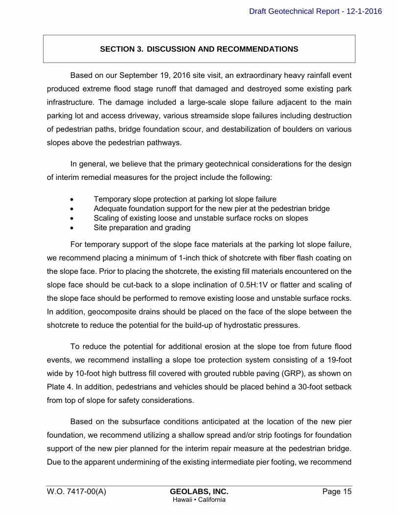
SECTION 3. DISCUSSION AND RECOMMENDATIONS
Based on our September 19, 2016 site visit, an extraordinary heavy rainfall event
produced extreme flood stage runoff that damaged and destroyed some existing park
infrastructure. The damage included a large-scale slope failure adjacent to the main
parking lot and access driveway, various streamside slope failures including destruction
of pedestrian paths, bridge foundation scour, and destabilization of boulders on various
slopes above the pedestrian pathways.
In general, we believe that the primary geotechnical considerations for the design
of interim remedial measures for the project include the following:
• Temporary slope protection at parking lot slope failure • Adequate foundation support for the new pier at the pedestrian bridge • Scaling of existing loose and unstable surface rocks on slopes • Site preparation and grading
For temporary support of the slope face materials at the parking lot slope failure,
we recommend placing a minimum of 1-inch thick of shotcrete with fiber flash coating on
the slope face. Prior to placing the shotcrete, the existing fill materials encountered on the
slope face should be cut-back to a slope inclination of 0.5H:1V or flatter and scaling of
the slope face should be performed to remove existing loose and unstable surface rocks.
In addition, geocomposite drains should be placed on the face of the slope between the
shotcrete to reduce the potential for the build-up of hydrostatic pressures.
To reduce the potential for additional erosion at the slope toe from future flood
events, we recommend installing a slope toe protection system consisting of a 19-foot
wide by 10-foot high buttress fill covered with grouted rubble paving (GRP), as shown on
Plate 4. In addition, pedestrians and vehicles should be placed behind a 30-foot setback
from top of slope for safety considerations.
Based on the subsurface conditions anticipated at the location of the new pier
foundation, we recommend utilizing a shallow spread and/or strip footings for foundation
support of the new pier planned for the interim repair measure at the pedestrian bridge.
Due to the apparent undermining of the existing intermediate pier footing, we recommend
Draft Geotechnical Report - 12-1-2016

SECTION 3. DISCUSSION AND RECOMMENDATIONS
W.O. 7417-00(A) GEOLABS, INC. Page 16
Hawaii • California
embedding the new footing to a depth equal to the depth of the existing intermediate pier
footing, which we have estimated to be approximately 9.5 feet below the existing ground
surface.
In general, the on-site granular soils may be re-used as a source of general fill
material, provided they are free of vegetation, deleterious materials, and rock fragments
greater than 6 inches in maximum dimension. In addition, general fill materials should
contain less than 15 percent particles passing the No. 200 sieve.
3.1 Temporary Slope Protection at Parking Lot Slope Failure Based on our site reconnaissance, the affected slope adjacent to the main parking
lot and access driveway is approximately 180 feet in length and stands approximately
50 to 60 feet above Wailuku Stream, which is at the base of the slope. It appears an
approximate 6 to 10-foot wide wedge of slope face material was lost during the full height
slope failure. The failed slope now averages about a 0.25H:1V inclination from top to
bottom with some sub-vertical slope segments. An undulating top of cliff has formed within
about 7 to 12 feet of the existing driveway guardrail and pavement.
As previously mentioned, our borings at the parking lot slope failure generally
encountered a pavement structure overlying about 20 to 40 feet of fill material consisting
of very dense gravel, cobbles, and boulders with some silty sand and a colluvial/alluvial
deposit consisting of very dense gravel, cobbles, and boulders with some clayey sand to
the maximum depth explored of about 81.5 feet below the existing ground surface.
Items pertaining to the temporary slope protection at the parking lot slope failure
are addressed in the subsequent subsections and include the following:
1. Temporary Traffic Barrier 2. Site Preparation 3. Slope Cut-Back 4. Slope Scaling 5. Shotcrete Facing 6. Drainage 7. Slope Toe Protection
Ideally, remedial measures for the slope protection would consist of the installation
of soil nails and a thick shotcrete layer on the slope face. Due to cost and time constraints,
Draft Geotechnical Report - 12-1-2016

SECTION 3. DISCUSSION AND RECOMMENDATIONS
W.O. 7417-00(A) GEOLABS, INC. Page 17 Hawaii • California
we understand that a temporary interim repair is desired. Therefore, the placement of an
initial shotcrete layer will be performed for the temporary repair. We assume that the
permanent repair will be performed shortly thereafter. Should the permanent repair be
delayed for an extended amount of time, repair of the thin initial shotcrete layer may be
required.
A Geolabs representative should monitor the temporary slope protection
operations to observe whether undesirable materials are encountered during the
excavation process, and to confirm whether the exposed soil conditions are similar to
those assumed herein.
Temporary Traffic Barrier
We understand park usage/traffic by the public is generally high with a steady
stream of arriving and departing sightseers on a daily basis. Considering the top
of the failed slope area is about 7 to 12 feet away from the existing driveway
guardrail and pavement, we recommend installing temporary traffic barriers at
least 30 feet away from the top of failed slope as a safety precaution. The traffic
barriers should be placed along the entire length of the parking lot and should
remain in-place until a long-term repair such as soil nails and additional shotcrete
are installed.
Site Preparation
At the on-set of earthwork, the area within the contract grading limits at the parking
lot slope failure should be cleared and grubbed thoroughly. Vegetation, debris,
deleterious materials, and other unsuitable materials should be removed and
disposed of properly off-site or in a designated area to reduce the potential for
contamination of the excavated materials.
Soft and yielding areas encountered during clearing and grubbing below areas
designated to receive fill, such as the slope toe protection, should be
over-excavated to expose firm material, and the resulting excavation should be
backfilled with 6-inch minus general fill material wrapped in a woven geotextile
fabric, such as Mirafi FW700 or equivalent. The excavated soft soils should not be
Draft Geotechnical Report - 12-1-2016

SECTION 3. DISCUSSION AND RECOMMENDATIONS
W.O. 7417-00(A) GEOLABS, INC. Page 18 Hawaii • California
re-used as fill materials and should be properly disposed of off-site or in
landscaped areas, if appropriate.
Slope Cut-Back
After clearing and grubbing, the existing fill materials encountered on the slope
face should be cut-back to a slope inclination of 0.5H:1V or flatter. Our borings
performed in this area generally encountered fill materials about 20 to 40 feet thick
consisting of medium dense gravel, cobbles, and boulders with some silty sand.
Therefore, we recommend cutting back at least the top 30 feet of the failed slope
area to a slope inclination of 0.5H:1V or flatter.
Slope Scaling
Slope scaling is the careful, systematic removal of loose rock and debris from a
slope face using manual labor methods such as hand and prybar removal. Slope
scaling is typically performed by an experienced scaling crew(s) working
methodically with hand tools from top down and across the slope face. Care is
taken to avoid over-steepening of the slope resulting in new rock slope instability.
After cutting back the fill materials encountered on the slope face, we recommend
scaling the slope to remove loose materials prior to placement of the geocomposite
drains and shotcrete.
Shotcrete Facing
For temporary support of the slope face materials, we recommend placing a
minimum of 1-inch thick of shotcrete with fiber flash coating. Shotcrete should have
a minimum compressive strength at 28 days of 4,000 pounds per square inch (psi)
and have a maximum 0.45 water to cement ratio. A shrinkage reducing admixture,
such as Eclipse or Master Life AS20 or equivalent, should be added at a dosage
of 128 ounces per cubic yard as recommended by the manufacturer. In addition,
shotcrete should contain 7.5 pounds of Strux 90/40 synthetic structural fiber, or
equivalent.
Draft Geotechnical Report - 12-1-2016
SECTION 3. DISCUSSION AND RECOMMENDATIONS
W.O. 7417-00(A) GEOLABS, INC. Page 19
Hawaii • California
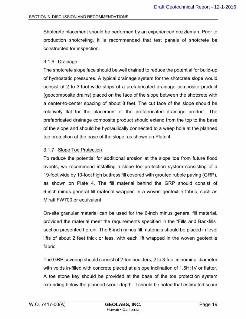
Shotcrete placement should be performed by an experienced nozzleman. Prior to
production shotcreting, it is recommended that test panels of shotcrete be
constructed for inspection.
Drainage
The shotcrete slope face should be well drained to reduce the potential for build-up
of hydrostatic pressures. A typical drainage system for the shotcrete slope would
consist of 2 to 3-foot wide strips of a prefabricated drainage composite product
(geocomposite drains) placed on the face of the slope between the shotcrete with
a center-to-center spacing of about 8 feet. The cut face of the slope should be
relatively flat for the placement of the prefabricated drainage product. The
prefabricated drainage composite product should extend from the top to the base
of the slope and should be hydraulically connected to a weep hole at the planned
toe protection at the base of the slope, as shown on Plate 4.
Slope Toe Protection
To reduce the potential for additional erosion at the slope toe from future flood
events, we recommend installing a slope toe protection system consisting of a
19-foot wide by 10-foot high buttress fill covered with grouted rubble paving (GRP),
as shown on Plate 4. The fill material behind the GRP should consist of
6-inch minus general fill material wrapped in a woven geotextile fabric, such as
Mirafi FW700 or equivalent.
On-site granular material can be used for the 6-inch minus general fill material,
provided the material meet the requirements specified in the “Fills and Backfills”
section presented herein. The 6-inch minus fill materials should be placed in level
lifts of about 2 feet thick or less, with each lift wrapped in the woven geotextile
fabric.
The GRP covering should consist of 2-ton boulders, 2 to 3-foot in nominal diameter
with voids in-filled with concrete placed at a slope inclination of 1.5H:1V or flatter.
A toe stone key should be provided at the base of the toe protection system
extending below the planned scour depth. It should be noted that estimated scour
Draft Geotechnical Report - 12-1-2016

SECTION 3. DISCUSSION AND RECOMMENDATIONS
W.O. 7417-00(A) GEOLABS, INC. Page 20
Hawaii • California
depth at the failed parking lot slope area have not been provided at the time this
report was prepared. The toe stone should consist of 3 to 5-ton boulders with a
nominal diameter of about 4 to 5 feet. To reduce the potential for hydrostatic
pressures to build-up behind the toe protection system, weep holes consisting of
6-inch diameter PVC pipes should be provided with a center-to-center spacing of
about 8 feet or less, as shown on Plate 4.
3.2 Pedestrian Bridge Foundations The existing concrete footing supporting the intermediate pier on the eastern side
of the pedestrian bridge appears to have been exposed and undermined by heavy stream
flow scour. We understand it is desired to construct an additional pier support adjacent to
the existing intermediate pier foundation for the temporary interim repair.
Based on the subsurface conditions anticipated at the location of the new pier
foundation, we recommend utilizing a shallow spread and/or strip footings for foundation
support of the new pier planned at the pedestrian bridge. An allowable bearing pressure
of up to 4,000 pounds per square foot (psf) may be utilized for the design of bridge
foundations bearing on the underlying dense gravelly cobbles and boulders. This bearing
value is for supporting dead-plus-live loads and may be increased by one-third (1/3) for
transient loads, such as those caused by wind or seismic forces.
To provide uniform bearing support of the foundations, we recommend placing a
minimum 6-inch thick layer of mud slab consisting of lean concrete or mortar below the
footings to serve as a leveling course. We do not recommend the use of soil type backfills
below and along the stream side of the bridge footing because the footings are located
adjacent to an active waterway.
Due to the apparent undermining of the existing intermediate pier footing, we
recommend embedding the new footing to a depth greater than or equal to the depth of
the existing intermediate pier footing, which we have estimated to be approximately
9.5 feet below the existing ground surface. Soft and/or loose materials encountered at the
bottom of the footing excavations should be over-excavated to expose the underlying
dense gravelly cobbles and boulders. The over-excavation should be backfilled with lean
Draft Geotechnical Report - 12-1-2016

SECTION 3. DISCUSSION AND RECOMMENDATIONS
W.O. 7417-00(A) GEOLABS, INC. Page 21 Hawaii • California
concrete, or the bottom of footing may be extended deeper to bear on the more competent
subgrade materials.
If foundations are designed and constructed in strict accordance with the
recommendations presented herein, we estimate total settlements of the foundations to
be less than 1 inch. Differential settlements between adjacent footings supported on
similar materials may be on the order of about 0.5 inch or less.
Lateral loads acting on the structures may be resisted by friction between the base
of the foundation and the bearing materials and by passive earth pressure developed
against the near-vertical faces of the embedded portion of foundations. A coefficient of
friction of 0.6 may be used for footings bearing directly on the dense gravely cobbles and
boulders. Resistance due to passive earth pressure should be neglected.
3.3 Short and Long Loop Trail Restoration Based on our observations, existing concrete walkways and staircases along
portions of both the Short and Long Loop Trails were significantly damaged and/or
destroyed by flood waters and stream bank erosion. We understand it is desired restore
at least portions of the trails with concrete walkways as part of the interim remedial
measures for the project.
Based on the subsurface conditions anticipated along the trail paths, we
recommend supporting the concrete walkways on at least 6 inches of non-expansive,
select granular fill material to provide a uniform bearing surface and level working
platform. A geotextile fabric, such as Mirafi 180N or equivalent, should be provided below
and along the sides of the non-expansive, select granular fill layer to reduce the potential
for migration of the granular fill material into the underlying cobbles and boulders. The
select granular fill material should be moisture-conditioned to above the optimum
moisture content and compacted to a minimum of 90 percent relative compaction. Prior
to placing the geotextile fabric and select granular fill material, the walkway subgrade
should be compacted to a firm and unyielding surface.
Draft Geotechnical Report - 12-1-2016

SECTION 3. DISCUSSION AND RECOMMENDATIONS
W.O. 7417-00(A) GEOLABS, INC. Page 22 Hawaii • California
We recommend concrete walkways be at least 4 inches thick. In addition, control
joints should be provided at intervals equal to the width of the walkways with expansion
joints at right-angle intersections.
3.4 Rockfall Hazard Mitigation Rockfall is a type of natural mass wasting process that is in-part responsible for
the evolution of mountain slopes. Rockfall is a common natural hazard due to the steep
volcanic terrain comprising the mountains and valleys of the Islands of Hawaii. Rockfall
activity involves the detachment of a rock mass from the slope face and the fall of rock
materials under the force of gravity. Rockfall may involve a single unstable block of rock
outcrop or it may involve a rockslide which encompasses multiple rock components.
Falling rock behavior can be complicated by the varying character of the ground
surface and topography encountered along the rock fall line. Rocks may either roll,
bounce, or have combined movement vectors. Falling rock may also hang up temporarily
or permanently on the slope without reaching the bottom under the effects of terrain
roughness, topography, vegetation, and the presence of natural features such as berms
and terraces formed by other rock outcroppings.
Under the current state of engineering practice combined with the use of proven
rockfall control methods, it is still impractical to mitigate 100 percent of all potential rockfall
activity at a site. However, with careful engineering and quality construction during the
installation of appropriate rockfall mitigation controls, the risk for rockfall activity can be
substantially reduced.
For this project, the identified potential rockfall hazards represent weakly to
moderately consolidated colluvial and alluvial cobbles and boulders with soil matrix. Due
to the type of rock deposit material composing the slopes, including a general wide range
in rock shapes and degrees of inter-grain cementation, traditional geologic mapping of
slope face rock fractures and discontinuities is not applicable. Thus, the focus of our
evaluation is based on capturing the anticipated potential rockfall adjacent to the trail
pathways or providing appropriate setbacks for debris catchment or hazard avoidance.
Draft Geotechnical Report - 12-1-2016

SECTION 3. DISCUSSION AND RECOMMENDATIONS
W.O. 7417-00(A) GEOLABS, INC. Page 23
Hawaii • California
Rock Slope Scaling
Rock slope scaling is the careful, systematic removal of loose rock and debris from
a slope face using manual labor methods such as hand and prybar removal.
Mechanized rock slope scaling is undesirable at this project site due to the
potential for inadvertent overly-intensive rock removal causing rock slope
instability. Rock slope scaling is typically performed by an experienced scaling
crew(s) working methodically with hand tools from top down and across the slope
face. Care is taken to avoid over-steepening of the slope resulting in new rock
slope instability. Occasionally, extra slope scaling effort is needed to stabilize local
rock outcroppings or interconnected masses of fractured rock material in order to
develop a stabilized slope face.
Slope scaling is recommended as part of the interim remedial repairs to reduce the
volume of potential rockfall involving the existing loose and unstable surface rocks
on the slope. Slope scaling would need to be repeated at intervals without a
protective fence structure along the slope toe to maintain some level of limited
hazard reduction for pedestrians. Slope scaling as a stand-alone improvement is
considered an interim mitigation measure that must be repeated to maintain the
hazard reduction.
If rockfall mitigation effort is not performed, uncontrolled and potentially dangerous
rockfall impact at the pathway is likely and should be expected to occur at some
time due to the presence of appreciable source rock materials on the slope.
Single Boulder Removal
Based on our site observations, a large boulder of approximately 10 feet in
diameter was observed to be perched precariously above a portion of the lower
loop trail, as shown on the Site Plan, Plate 2, and Photograph No. 16 on Plate 3.8.
This boulder was originally documented in our preliminary rockfall hazard
assessment of the existing slope conditions at the park in January 2016. At the
time of our January 2016 assessment, we observed the boulder to be set on
sloping ground with several small boulders lodged underneath. We determined the
lodged boulders provided some basal support and marginal stability against
Draft Geotechnical Report - 12-1-2016
SECTION 3. DISCUSSION AND RECOMMENDATIONS
W.O. 7417-00(A) GEOLABS, INC. Page 24
Hawaii • California
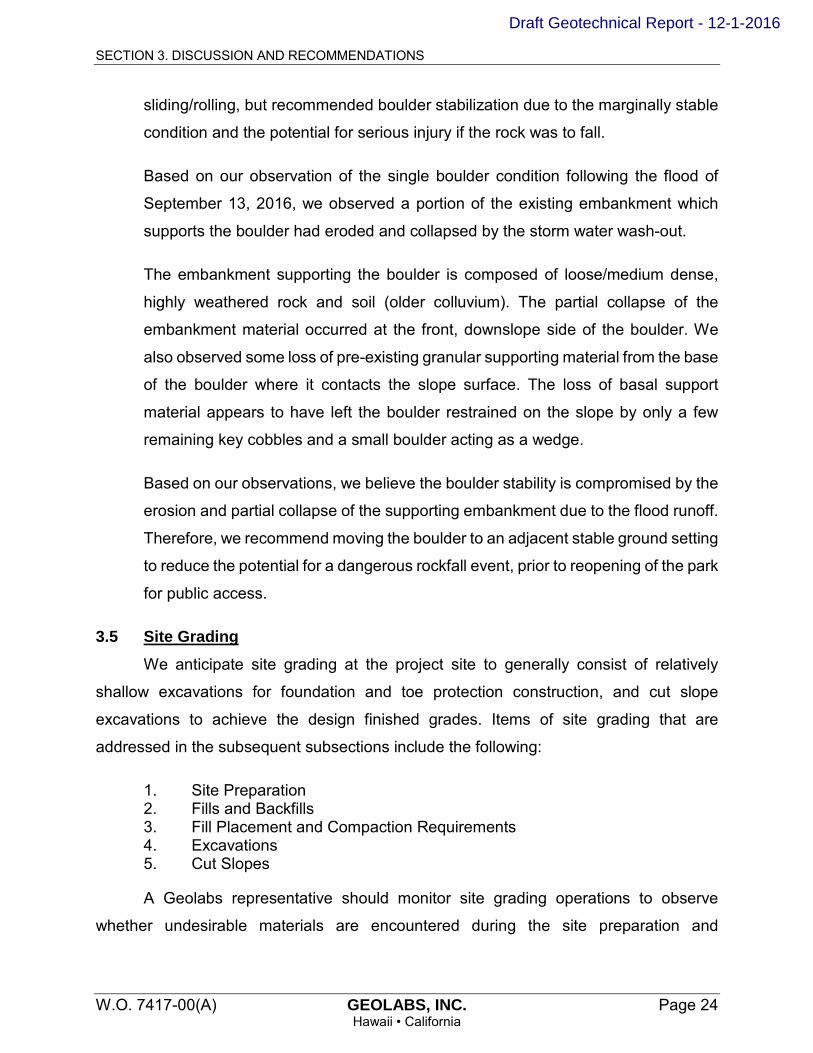
sliding/rolling, but recommended boulder stabilization due to the marginally stable
condition and the potential for serious injury if the rock was to fall.
Based on our observation of the single boulder condition following the flood of
September 13, 2016, we observed a portion of the existing embankment which
supports the boulder had eroded and collapsed by the storm water wash-out.
The embankment supporting the boulder is composed of loose/medium dense,
highly weathered rock and soil (older colluvium). The partial collapse of the
embankment material occurred at the front, downslope side of the boulder. We
also observed some loss of pre-existing granular supporting material from the base
of the boulder where it contacts the slope surface. The loss of basal support
material appears to have left the boulder restrained on the slope by only a few
remaining key cobbles and a small boulder acting as a wedge.
Based on our observations, we believe the boulder stability is compromised by the
erosion and partial collapse of the supporting embankment due to the flood runoff.
Therefore, we recommend moving the boulder to an adjacent stable ground setting
to reduce the potential for a dangerous rockfall event, prior to reopening of the park
for public access.
3.5 Site Grading We anticipate site grading at the project site to generally consist of relatively
shallow excavations for foundation and toe protection construction, and cut slope
excavations to achieve the design finished grades. Items of site grading that are
addressed in the subsequent subsections include the following:
1. Site Preparation 2. Fills and Backfills 3. Fill Placement and Compaction Requirements 4. Excavations 5. Cut Slopes
A Geolabs representative should monitor site grading operations to observe
whether undesirable materials are encountered during the site preparation and
Draft Geotechnical Report - 12-1-2016

SECTION 3. DISCUSSION AND RECOMMENDATIONS
W.O. 7417-00(A) GEOLABS, INC. Page 25 Hawaii • California
excavation, and to confirm whether the exposed soil conditions are similar to those
assumed herein.
Site Preparation
At the on-set of earthwork, the area within the contract grading limits should be
cleared and grubbed thoroughly. Vegetation, debris, deleterious materials, and other
unsuitable materials should be removed and disposed of properly off-site or in a
designated area to reduce the potential for contamination of the excavated materials.
Soft and yielding areas encountered during clearing and grubbing below areas
designated to receive fill, such as the slope toe protection and concrete walkways,
should be over excavated to expose firm material, and the resulting excavation
should be backfilled with 6-inch minus general fill material wrapped in a woven
geotextile fabric, such as Mirafi FW700 or equivalent. The excavated soft soils should
not be re-used as fill materials and should be properly disposed of off-site or in
landscaped areas, if appropriate. After clearing and grubbing, areas to receive fills
should be compacted to a firm and unyielding surface.
Saturation and subsequent yielding of the exposed subgrade due to inclement
weather and poor drainage may require over-excavating the soft areas and replacing
these areas with engineered fill. A Geolabs representative in the field should evaluate
the need for over-excavation due to soft subgrade soil conditions.
Fills and Backfills
In general, the on-site granular soils may be re-used as a source of general fill
material, provided they are free of vegetation, deleterious materials, and rock
fragments greater than 6 inches in maximum dimension. In addition, general fill
materials should contain no more than 15 percent particles passing the No. 200
sieve.
We do not anticipate the need for imported general fill materials for the project.
However, if imported general fill materials are needed, Geolabs should be consulted
to provide supplemental recommendations for imported fill materials needed for the
project.
Draft Geotechnical Report - 12-1-2016

SECTION 3. DISCUSSION AND RECOMMENDATIONS
W.O. 7417-00(A) GEOLABS, INC. Page 26 Hawaii • California
Imported fill materials should consist of crushed basalt or coral. The select granular
fill should be well graded from coarse to fine with particles no larger than 3 inches in
largest dimension and should contain between 10 and 30 percent particles passing
the No. 200 sieve. The material should have a laboratory CBR value of 20 or more
and should have a maximum swell of less than 1 percent when tested in accordance
with ASTM D1883. Geolabs should test imported fill materials a minimum of 7 days
prior to being transported to the project site for the intended use.
Fill Placement and Compaction Requirements
General fill materials should be placed in level lifts not exceeding 2 feet in loose
thickness, moisture-conditioned to above the optimum moisture content, and
compacted to at least 90 percent relative compaction. The non-expansive select
granular fill materials should be placed in level lifts of about 8 inches in loose
thickness, moisture-conditioned to above the optimum moisture, and compacted to
at least 90 percent relative compaction.
Relative compaction refers to the in place dry density of soil expressed as a
percentage of the maximum dry density of the same soil established in accordance
with ASTM D1557. Optimum moisture is the water content (percentage by weight)
corresponding to the maximum dry density.
Compaction should be accomplished by sheepsfoot rollers, vibratory rollers, or other
types of acceptable compaction equipment. Water tamping, jetting, or ponding
should not be allowed to compact the fills.
Excavations
Based on the anticipated grading and our field exploration, excavation for this project
will generally consist of shallow excavations for foundation and toe protection
construction and cut slope excavations to achieve the design finished grades. The
planned excavations will likely encounter cobbles and boulders with some soil. It is
anticipated that most of the material may be excavated with normal heavy excavation
equipment. However, deep excavations and boulder excavations may require the
Draft Geotechnical Report - 12-1-2016

SECTION 3. DISCUSSION AND RECOMMENDATIONS
W.O. 7417-00(A) GEOLABS, INC. Page 27 Hawaii • California
use of hoerams. Special care should be taken to avoid inadvertent overly-intensive
rock removal causing slope instability.
The above discussions regarding the rippability of the subsurface materials are
based on field data from the borings drilled at the site. Contractors should be
encouraged to examine the site conditions and the subsurface data to make their
own reasonable and prudent interpretation.
Cut Slopes
Cut slopes at the parking lot slope failure should be designed with a slope inclination
of 0.5 horizontal to one vertical (0.5H:1V) or flatter, provided shotcrete is placed along
the slope face in the interim and additional shotcrete and soil nails be provided for
long-term stability.
3.6 Design Review Preliminary and final drawings and specifications for the project should be
forwarded to Geolabs for review and written comments prior to bid solicitation for
construction. This review is necessary to evaluate conformance of the plans and
specifications with the intent of the foundation and earthwork recommendations provided
herein. If this review is not made, Geolabs cannot be responsible for misinterpretation of
our recommendations.
3.7 Post-Design Services/Services During Construction Geolabs should be retained to provide geotechnical engineering services during
construction. The critical items of construction monitoring that require "Special Inspection"
include the following:
• Observation of site and subgrade preparation• Observation of cut slope excavations• Observation of shotcrete placement• Observation of toe protection construction• Observation of fill and backfill placement• Observation of the bridge foundation excavation• Observation of slope scaling• Observation of single boulder stabilization/relocation
Draft Geotechnical Report - 12-1-2016
SECTION 3. DISCUSSION AND RECOMMENDATIONS
W.O. 7417-00(A) GEOLABS, INC. Page 28
Hawaii • California
A Geolabs representative also should monitor other aspects of earthwork
construction to observe compliance with the design concepts, specifications, or
recommendations and to expedite suggestions for design changes that may be required
in the event that subsurface conditions differ from those anticipated at the time this report
was prepared. Geolabs should be accorded the opportunity to provide geotechnical
engineering services during construction to confirm our assumptions in providing the
recommendations presented herein.
If the actual exposed subsurface conditions encountered during construction differ
from those assumed or considered herein, Geolabs should be contacted to review and/or
revise the geotechnical recommendations presented herein.
END OF DISCUSSION AND RECOMMENDATIONS
Draft Geotechnical Report - 12-1-2016

W.O. 7417-00(A) GEOLABS, INC. Page 29
Hawaii • California
SECTION 4. LIMITATIONS
The analyses and recommendations submitted herein are based in part upon
information obtained from the site reconnaissance and field borings. Variations of the
subsurface conditions between and beyond the field borings may occur, and the nature
and extent of these variations may not become evident until construction is underway. If
variations then appear evident, it will be necessary to re-evaluate the recommendations
presented herein.
The field boring locations indicated herein are approximate, having been estimated
by taping from visible features shown on the Preliminary Topographic Survey Plan
transmitted by Wilson Okamoto Corporation on November 16, 2016. Elevations of the
borings were estimated from contours and spot elevations shown on the same plan. The
field boring locations and elevations should be considered accurate only to the degree
implied by the methods used.
The stratification breaks shown on the graphic representations of the borings
depict the approximate boundaries between soil types and, as such, may denote a
gradual transition. Water level data from the borings were measured at the times shown
on the graphic representations and/or presented in the text of this report. These data have
been reviewed and interpretations made in the formulation of this report. Considering the
project site is located adjacent to Wailuku and Iao Streams, the groundwater levels may
vary in response to the water level in the streams. In addition, it should be noted that the
groundwater levels are subject to change due to rainfall, seasonal precipitation, surface
water runoff, and other factors.
This report has been prepared for the exclusive use of Wilson Okamoto
Corporation and the State of Hawaii, Department of Land and Natural Resources and
their project consultants for specific application to the design of interim remedial
measures for the Iao Valley State Monument Flood Repairs project in accordance with
generally accepted geotechnical engineering principles and practices. No warranty is
expressed or implied.
Draft Geotechnical Report - 12-1-2016

SECTION 4. LIMITATIONS
W.O. 7417-00(A) GEOLABS, INC. Page 30 Hawaii • California
This report has been prepared solely for the purpose of assisting the design
engineers in the design of interim remedial measures for the project. Therefore, this report
may not contain sufficient data, or the proper information, to serve as a basis for detailed
construction cost estimates.
The owner/client should be aware that unanticipated soil conditions are commonly
encountered. Unforeseen subsurface conditions, such as perched groundwater, soft
deposits, hard layers or cavities, may occur in localized areas and may require additional
probing or corrections in the field (which may result in construction delays) to attain a
properly constructed project. Therefore, a sufficient contingency fund is recommended to
accommodate these possible extra costs.
This geotechnical engineering exploration conducted at the project site was not
intended to investigate the potential presence of hazardous materials existing at the
project site. It should be noted that the equipment, techniques, and personnel used to
conduct a geo-environmental exploration differ substantially from those applied in
geotechnical engineering.
END OF LIMITATIONS
Draft Geotechnical Report - 12-1-2016

W.O. 7417-00(A) GEOLABS, INC. Page 31 Hawaii • California
CLOSURE
The following plates and appendices are attached and complete this report:
Project Location Map .............................................................................................. Plate 1
Site Plan ................................................................................................................. Plate 2
Photographs of Observed Storm Damage ........................................... Plates 3.1 thru 3.8
Temporary Slope Protection at Parking Lot Slope Failure ...................................... Plate 4
Field Exploration ............................................................................................. Appendix A
Laboratory Tests ............................................................................................. Appendix B
Photographs of Rock Cores ............................................................................ Appendix C
-ΩΩΩΩΩΩΩΩΩ-
Respectfully submitted,
GEOLABS, INC.
DRAFT By ________________________
Andrew J. Felkel, P.E. Project Engineer
DRAFT By ________________________
Gerald Y. Seki, P.E. Vice President
GS:AJF:as
h:\7400Series\7417-00A.ajf1
Draft Geotechnical Report - 12-1-2016

PLATES
Draft Geotechnical Report - 12-1-2016
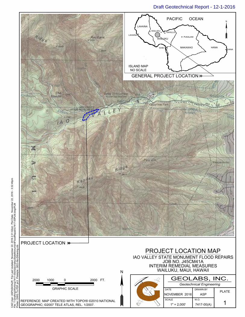
WAILUKU, MAUI, HAWAIIINTERIM REMEDIAL MEASURES
GRAPHIC SCALE
10002000 20000 FT.
PROJECT LOCATION
GENERAL PROJECT LOCATION
NOVEMBER 2016
1" = 2,000'
DATE
SCALE
17417-00(A)
DRAWN BY
ASPW.O.
PLATE
N
N
PROJECT LOCATION MAP
ISLAND MAPNO SCALE
LAHAINA
LAHAINA
WAILUKUKAHULUI
WAILUKU
PACIFIC OCEAN
PUKALANI
MAKAWAOKIHEI HANAHANA
CA
D U
ser:
AS
PA
SIO
NJR
File
Las
t Upd
ated
: Nov
embe
r 22,
201
6 2:
31:0
2pm
Plo
t Dat
e: N
ovem
ber 2
2, 2
016
- 3:3
2:46
pmFi
le: T
:\Dra
fting
\Wor
king
\741
7-00
(A)Ia
oVal
leyS
tate
Mon
umen
tFlo
odR
epai
rs\7
417-
00P
LM.d
wg\
PLM
Plo
tter:
DW
G T
o P
DF.
pc3
Plo
tsty
le: G
EO
-No-
Dith
erin
g.ct
b
REFERENCE: MAP CREATED WITH TOPO!® ©2010 NATIONALGEOGRAPHIC; ©2007 TELE ATLAS, REL. 1/2007.
JOB NO. J45CM41A
Draft Geotechnical Report - 12-1-2016

APPROXIMATE BORING LOCATION
LEGEND: NINTERIM REMEDIAL MEASURES
WAILUKU, MAUI, HAWAII
7417-00(A)
DRAWN BY
ASP
JOB NO. J45CM41A
1" = 80'
NOVEMBER 2016SCALE
DATE
W.O.
SITE PLAN
2
PLATE
GRAPHIC SCALE
400 80 160 240 FT.
CA
D U
ser:
AS
PA
SIO
NJR
File
Las
t Upd
ated
: Nov
embe
r 23,
201
6 4:
27:1
7pm
Plo
t Dat
e: D
ecem
ber 0
1, 2
016
- 4:4
0:02
pmFi
le: T
:\Dra
fting
\Wor
king
\741
7-00
(A)Ia
oVal
leyS
tate
Mon
umen
tFlo
odR
epai
rs\7
417-
00S
ITE
PLA
N.d
wg\
Site
Pla
nP
lotte
r: D
WG
To
PD
F.pc
3 P
lots
tyle
: GE
O-N
o-D
ither
ing-
Blu
e-B
orin
g.ct
b
REFERENCE: PRELIMINARY TOPOGRAPHIC SURVEY PLAN RECEIVED FROM WILSON OKAMOTO CORPORATION ON NOVEMBER 16, 2016.
IAO STREAM
B-1
B-2B-3
B-4
B-5
B-6
SINGLE BOULDERRELOCATION
LIMITS OF SLOPESCALING
LIMITS OF SLOPEPROTECTION AREAPHASE 1
LIMITS OF SLOPEPROTECTION AREAPHASE 2
Draft Geotechnical Report - 12-1-2016

Iao State Monument Flood Repairs Job No. J45CM41A, Interim Remedial Measures
Wailuku, Maui, Hawaii
W.O. 7417-00(A) GEOLABS, INC. PLATE 3.1
Hawaii • California
Photograph No. 1: View upstream of the parking lot slope failure site on September 13, 2016
Photograph No. 2: View downstream of the parking lot slope failure site.
Draft Geotechnical Report - 12-1-2016

Iao State Monument Flood Repairs Job No. J45CM41A, Interim Remedial Measures
Wailuku, Maui, Hawaii
W.O. 7417-00(A) GEOLABS, INC. PLATE 3.2
Hawaii • California
Photograph No. 3: Existing top of slope condition with view in the upstream direction.
Photograph No. 4: Existing top of slope condition with view in the downstream direction.
Draft Geotechnical Report - 12-1-2016

Iao State Monument Flood Repairs Job No. J45CM41A, Interim Remedial Measures
Wailuku, Maui, Hawaii
W.O. 7417-00(A) GEOLABS, INC. PLATE 3.3
Hawaii • California
Photograph No. 5: Existing condition of the parking lot slope failure site from the stream elevation. Note the semi-consolidated character of the older colluvial deposits exposed in the lower portion of the slope, in contrast to the overlying unconsolidated overcast fill materials comprising the upper portion of the slope.
Photograph No. 6: Closer view of the semi-consolidated older colluvial materials comprising the lower slope at the parking lot slope failure site.
Draft Geotechnical Report - 12-1-2016
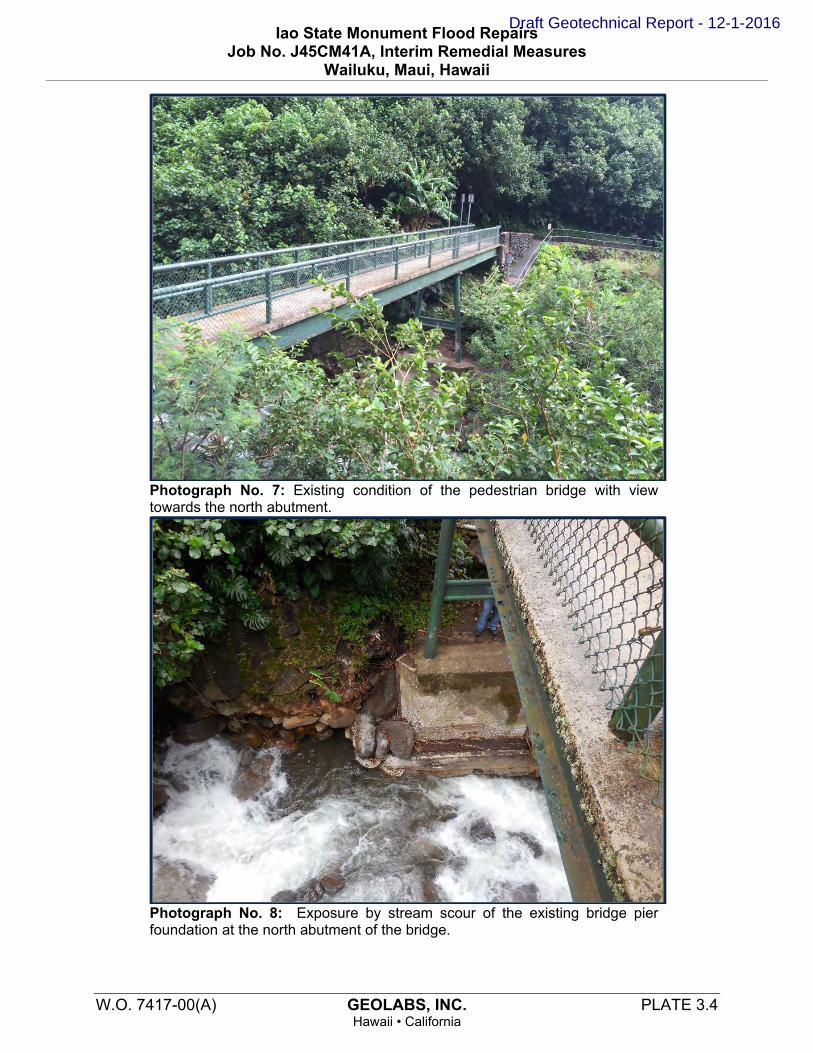
Iao State Monument Flood Repairs Job No. J45CM41A, Interim Remedial Measures
Wailuku, Maui, Hawaii
W.O. 7417-00(A) GEOLABS, INC. PLATE 3.4
Hawaii • California
Photograph No. 7: Existing condition of the pedestrian bridge with view towards the north abutment.
Photograph No. 8: Exposure by stream scour of the existing bridge pier foundation at the north abutment of the bridge.
Draft Geotechnical Report - 12-1-2016

Iao State Monument Flood Repairs Job No. J45CM41A, Interim Remedial Measures
Wailuku, Maui, Hawaii
W.O. 7417-00(A) GEOLABS, INC. PLATE 3.5
Hawaii • California
Photograph No. 9: Exposure by stream scour of the existing bridge pier foundation at the northern abutment of the bridge.
Photograph No. 10: Bank failure and loss of pathway and railings at the short loop trail.
Draft Geotechnical Report - 12-1-2016
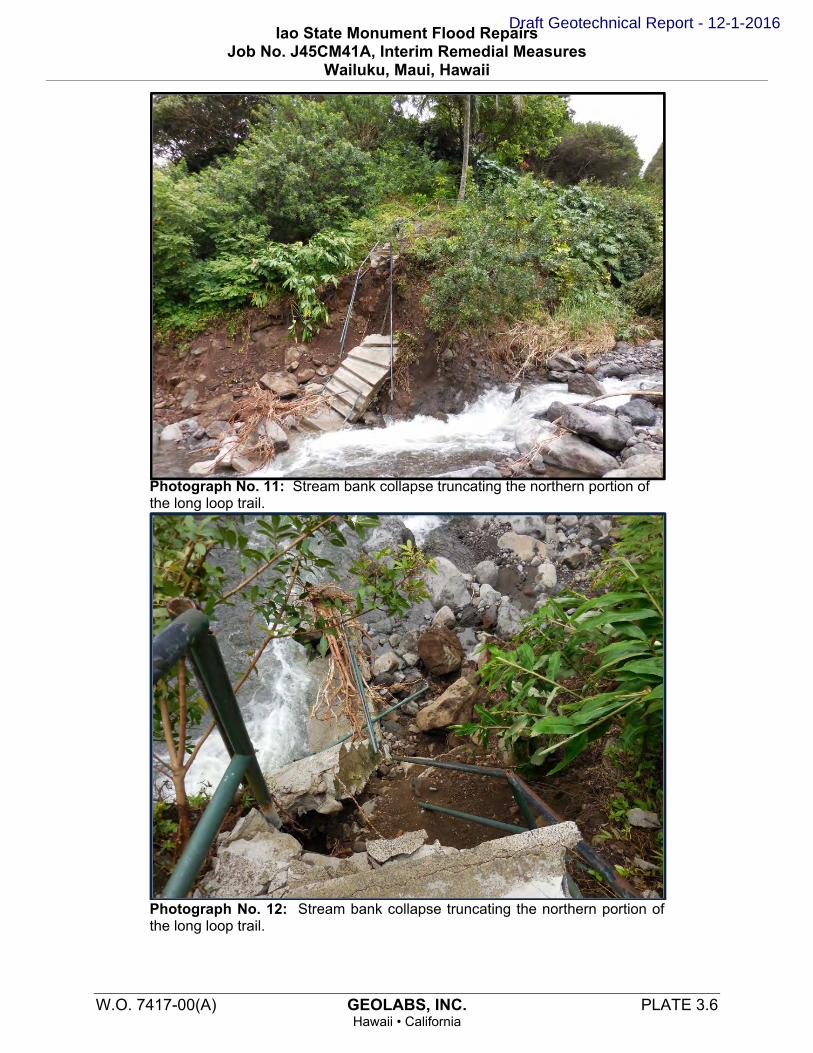
Iao State Monument Flood Repairs Job No. J45CM41A, Interim Remedial Measures
Wailuku, Maui, Hawaii
W.O. 7417-00(A) GEOLABS, INC. PLATE 3.6
Hawaii • California
Photograph No. 11: Stream bank collapse truncating the northern portion of the long loop trail.
Photograph No. 12: Stream bank collapse truncating the northern portion of the long loop trail.
Draft Geotechnical Report - 12-1-2016

Iao State Monument Flood Repairs Job No. J45CM41A, Interim Remedial Measures
Wailuku, Maui, Hawaii
W.O. 7417-00(A) GEOLABS, INC. PLATE 3.7
Hawaii • California
Photograph No. 13: Portion of the concrete pathway on the long loop trail destroyed by floodwater.
Photograph No. 14: Undermining and exposure of existing basaltic cobbles and boulders mantling the taller slopes adjacent to the pathway. Site of proposed slope scaling.
Draft Geotechnical Report - 12-1-2016

Iao State Monument Flood Repairs Job No. J45CM41A, Interim Remedial Measures
Wailuku, Maui, Hawaii
W.O. 7417-00(A) GEOLABS, INC. PLATE 3.8
Hawaii • California
Photograph No. 15: Undermining and exposure of existing basaltic cobbles and boulders mantling the taller slopes adjacent to the pathway. Site of proposed slope scaling.
Photograph No. 16: Single large boulder proposed for stabilization along a section of the remaining portion of the long loop trail.
Draft Geotechnical Report - 12-1-2016
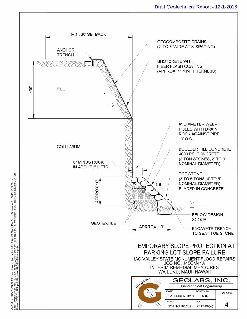
7417-00(A)
DRAWN BY
ASP
NOT TO SCALE
SEPTEMBER 2016SCALE
DATE
W.O.
4
PLATE
CA
D U
ser:
AS
PA
SIO
NJR
File
Las
t Upd
ated
: Nov
embe
r 23,
201
6 4:
27:0
5pm
Plo
t Dat
e: D
ecem
ber 0
1, 2
016
- 2:2
4:53
pmFi
le: T
:\Dra
fting
\Wor
king
\741
7-00
(A)Ia
oVal
leyS
tate
Mon
umen
tFlo
odR
epai
rs\7
417-
00(A
)Rem
edia
lMea
sure
Det
ails
.dw
g\TO
OP
EN
Plo
tter:
DW
G T
o P
DF.
pc3
Plo
tsty
le: G
EO
-No-
Dith
erin
g.ct
b
6" MINUS ROCKIN ABOUT 2' LIFTS
ANCHORTRENCH
GEOCOMPOSITE DRAINS(2' TO 3' WIDE AT 8' SPACING)
SHOTCRETE WITHFIBER FLASH COATING(APPROX. 1" MIN. THICKNESS)
6" DIAMETER WEEPHOLES WITH DRAINROCK AGAINST PIPE,10' O.C.
BOULDER FILL CONCRETE4000 PSI CONCRETE(2 TON STONES, 2' TO 3'NOMINAL DIAMETER)
TOE STONE(3 TO 5 TONS, 4' TO 5'NOMINAL DIAMETER)PLACED IN CONCRETE
EXCAVATE TRENCHTO SEAT TOE STONE
GEOTEXTILE
MIN. 30' SETBACK
AP
PR
OX
10'
APRROX. 19'
FILL
COLLUVIUM
1
~ 12
~30'
WAILUKU, MAUI, HAWAIIINTERIM REMEDIAL MEASURES
JOB NO. J45CM41A
4'
1.51
BELOW DESIGNSCOUR
Draft Geotechnical Report - 12-1-2016

Draft Geotechnical Report - 12-1-2016

W.O. 7417-00(A) GEOLABS, INC. DECEMBER 2016 Page A-1
Hawaii • California
A P P E N D I X A
Field Exploration
We explored the subsurface conditions at the project site by drilling and sampling six borings, designated as Boring Nos. 1 through 6, extending to depths ranging from about 19 to 81.5 feet below the existing ground surface. The approximate boring locations are shown on the Site Plan, Plate 2. The borings were drilled using a truck-mounted drill rig and portable drilling equipment equipped with continuous flight augers and coring tools.
Our geologists classified the materials encountered in the borings by visual and textural examination in the field in general accordance with ASTM D2488, Standard Practice for Description and Identification of Soils, and monitored the drilling operations on a near-continuous (full-time) basis. These classifications were further reviewed visually and by testing in the laboratory. Soils were classified in general accordance with ASTM D2487, Standard Practice for Classification of Soils for Engineering Purposes (Unified Soil Classification System), as shown on the Soil Log Legend, Plate A-0.1. Deviations made to the soil classification in accordance with ASTM D2487 are described on the Soil Classification Log Key, Plate A-0.2. Graphic representations of the materials encountered are presented on the Logs of Borings, Plates A-1 through A-6.
Relatively “undisturbed” soil samples were obtained in general accordance with ASTM D3550-01(2007), Ring-Lined Barrel Sampling of Soils, by driving a 3-inch OD Modified California sampler with a 140-pound hammer falling 30 inches. In addition, some samples were obtained from the drilled borings in general accordance with ASTM D1586, Penetration Test and Split-Barrel Sampling of Soils, by driving a 2-inch OD standard penetration sampler using the same hammer and drop. The blow counts needed to drive the sampler the second and third 6 inches of an 18-inch drive are shown as the “Penetration Resistance” on the Logs of Borings at the appropriate sample depths. The penetration resistance shown on the logs of borings indicates the number of blows required for the specific sampler type used. The blow counts may need to be factored to obtain the Standard Penetration Test (SPT) blow counts.
Core samples of the rock materials encountered at the project site were obtained by using diamond core drilling techniques in general accordance with ASTM D2113, Diamond Core Drilling for Site Investigation. Core drilling is a rotary drilling method that uses a hollow bit to cut into the rock formation. The rock material left in the hollow core of the bit is mechanically recovered for examination and description. Rock cores were described in general accordance with the Rock Description System, as shown on the Rock Log Legend, Plate A-0.3. The Rock Description System is based on the publication “Suggested Methods for the Quantitative Description of Discontinuities in Rock Masses” by the International Society for Rock Mechanics (March 1977).
Recovery (REC) is used as a subjective guide to the interpretation of the relative quality of rock masses. Recovery is defined as the actual length of material recovered from a coring attempt versus the length of the core attempt. For example, if 3.7 feet of material is
Draft Geotechnical Report - 12-1-2016

Appendix A Field Exploration
W.O. 7417-00(A) GEOLABS, INC. DECEMBER 2016 Page A-2 Hawaii • California
recovered from a 5.0-foot core run, the recovery would be 74 percent and would be shown on the Logs of Borings as REC = 74%.
The Rock Quality Designation (RQD) is also a subjective guide to the relative quality of rock masses. RQD is defined as the percentage of the core run in rock that is sound material in excess of 4 inches in length without discontinuities, discounting drilling induced fractures or breaks. If 2.5 feet of sound material is recovered from a 5.0-foot core run in rock, the RQD would be 50 percent and would be shown on the Logs of Borings as RQD = 50%. Generally, the following is used to describe the relative quality of the rock, based on the "Practical Handbook of Physical Properties of Rocks and Minerals."
Rock Quality RQD
(%)
Very Poor 0 – 25 Poor 25 – 50 Fair 50 – 75
Good 75 – 90 Excellent 90 – 100
Draft Geotechnical Report - 12-1-2016

A-0.1
UNCONSOLIDATED UNDRAINED TRIAXIALCOMPRESSION (ksf)
MORE THAN 50%OF COARSEFRACTION
RETAINED ONNO. 4 SIEVE
50% OR MORE OFCOARSE FRACTION
PASSINGTHROUGH NO. 4
SIEVE
MORE THAN 50%OF MATERIAL
RETAINED ON NO.200 SIEVE
50% OR MORE OFMATERIAL PASSINGTHROUGH NO. 200
SIEVE
TORVANE SHEAR (tsf)
(2-INCH) O.D. STANDARD PENETRATION TEST
(3-INCH) O.D. MODIFIED CALIFORNIA SAMPLE
INORGANIC SILTS AND VERY FINE SANDS,ROCK FLOUR, SILTY OR CLAYEY FINE SANDSOR CLAYEY SILTS WITH SLIGHT PLASTICITY
POORLY-GRADED GRAVELS, GRAVEL-SANDMIXTURES, LITTLE OR NO FINES
CLAYEY GRAVELS, GRAVEL-SAND-CLAYMIXTURES
WELL-GRADED SANDS, GRAVELLY SANDS,LITTLE OR NO FINES
POORLY-GRADED SANDS, GRAVELLYSANDS, LITTLE OR NO FINES
SILTY SANDS, SAND-SILT MIXTURES
CLAYEY SANDS, SAND-CLAY MIXTURES
LIQUID LIMIT50 OR MORE CH
NOTE: DUAL SYMBOLS ARE USED TO INDICATE BORDERLINE SOIL CLASSIFICATIONS
MH
SILTSAND
CLAYS
SILTSAND
CLAYSLIQUID LIMIT
LESS THAN 50
USCS TYPICALDESCRIPTIONS
GW
MORE THAN 12%FINES
WATER LEVEL OBSERVED IN BORING OVERNIGHT
HIGHLY ORGANIC SOILS
SILTY GRAVELS, GRAVEL-SAND-SILTMIXTURES
OL
PEAT, HUMUS, SWAMP SOILS WITH HIGHORGANIC CONTENTS
INORGANIC CLAYS OF LOW TO MEDIUMPLASTICITY, GRAVELLY CLAYS, SANDYCLAYS, SILTY CLAYS, LEAN CLAYS
Soil Log Legend
ORGANIC CLAYS OF MEDIUM TO HIGHPLASTICITY, ORGANIC SILTS
CLEAN SANDS
SANDS WITHFINES
SP
SANDS
GRAVELS
WELL-GRADED GRAVELS, GRAVEL-SANDMIXTURES, LITTLE OR NO FINES
ML
CL
OH
LESS THAN 5%FINES
GRAVELS WITHFINES
CLEANGRAVELS
GRAB SAMPLE
PLASTICITY INDEX (NP=NON-PLASTIC)
TV
LEGEND
WATER LEVEL OBSERVED IN BORING AT TIME OFDRILLINGWATER LEVEL OBSERVED IN BORING AFTER DRILLING
SM
MAJOR DIVISIONS
GP
MORE THAN 12%FINES SC
Plate
GM
FINE-GRAINED
SOILS
COARSE-GRAINED
SOILS
PT
LESS THAN 5%FINES
UNIFIED SOIL CLASSIFICATION SYSTEM (USCS)
ORGANIC SILTS AND ORGANIC SILTYCLAYS OF LOW PLASTICITY
SW
GC
INORGANIC SILT, MICACEOUS ORDIATOMACEOUS FINE SAND OR SILTYSOILS
INORGANIC CLAYS OF HIGH PLASTICITY
PI
LL
TXUU
UNCONFINED COMPRESSIONOR UNIAXIAL COMPRESSIVE STRENGTH
CORE SAMPLE
SHELBY TUBE SAMPLE
LIQUID LIMIT (NP=NON-PLASTIC)
UC
GEOLABS, INC.
Geotechnical Engineering
LOG
LE
GEN
D F
OR
SO
IL 7
417-
00(A
).GP
J G
EOLA
BS.G
DT
11/
21/1
6
Draft Geotechnical Report - 12-1-2016

A-0.2
Medium SandFine Sand
#4 to #200 (4.75-mm to 0.075-mm)#4 to #10 (4.75-mm to 2-mm)
> 12 inches (305-mm)
3-inch to #4 (75-mm to 4.75-mm)
Sieve Number and / or Size
Gravel
#10 to #40 (2-mm to 0.425-mm)#40 to #200 (0.425-mm to 0.075-mm)
3 to 12 inches (75-mm to 305-mm)
Description
PP Readings(tsf)
2.0 - 4.0
> 4.0
N-Value (Blows/Foot)MCS0 - 4
RELATIVE DENSITY / CONSISTENCY
GRAIN SIZE DEFINITION
ABBREVIATIONS
N-Value (Blows/Foot)
0 - 7
Dry: Absence of moisture, dry to the touch
Moist: Damp but no visible water
Wet: Visible free water, usually soil is below water table
WOH: Weight of Hammer
WOR: Weight of Drill Rods
SPT: Standard Penetration Test Split-Spoon Sampler
MCS: Modified California Sampler
PP: Pocket Penetrometer
4 - 7
7 - 15
15 - 27
27 - 55
SPT0 - 2
> 55> 30
4 - 8
15 - 30
MOISTURE CONTENT DEFINITIONS
SPT0 - 4
4 - 10
10 - 30
30 - 50
> 50
MCS
Loose
EXAMPLE: Soil Containing 60% Gravel, 25% Sand, 15% Fines. Described as: SILTY GRAVEL with some sand
Plate
GRANULAR SOIL (- #200 <50%)
2 - 4
8 - 15
RelativeDensity
Very Loose
Dense
Very Dense
COHESIVE SOIL (- #200 50%)
PRIMARY constituents are composed of the largestpercent of the soil mass. Primary constituents arecapitalized and bold (i.e., GRAVEL, SAND)
PRIMARY constituents are based on plasticity. Primaryconstituents are capitalized and bold (i.e., CLAY, SILT)
SECONDARY constituents are composed of apercentage less than the primary constituent. If the soilmass consists of 12 percent or more fines content, acohesive constituent is used (SILTY or CLAYEY);otherwise, a granular constituent is used (GRAVELLYor SANDY) provided that the secondary constituentconsists of 20 percent or more of the soil mass.Secondary constituents are capitalized and bold (i.e.,SANDY GRAVEL, CLAYEY SAND) and precede theprimary constituent.
SECONDARY constituents are composed of apercentage less than the primary constituent, but morethan 20 percent of the soil mass. Secondary constituentsare capitalized and bold (i.e., SANDY CLAY, SILTYCLAY, CLAYEY SILT) and precede the primaryconstituent.
Sand
BouldersCobbles
Coarse Gravel 3-inch to 3/4-inch (75-mm to 19-mm)Fine Gravel 3/4-inch to #4 (19-mm to 4.75-mm)
GEOLABS, INC. CLASSIFICATION*
Granular Soils Cohesive Soils
Consistency
accessory descriptions compose of the following:with some: >12%with a little: 5 - 12%with traces of: <5%accessory descriptions are lower cased and follow thePrimary and Secondary Constituents(i.e., SILTY CLAY with some sand)
Very Soft
Soft
Medium Stiff
Stiff
Very Stiff
Hard
< 0.5
0.5 - 1.0
1.0 - 2.0
7 - 18
18 - 55
55 - 91
> 91
Medium Dense
Coarse Sand
(with deviations from ASTM D2488)Soil Classification Log Key
*Soil descriptions are based on ASTM D2488-09a, Visual-Manual Procedure, with theabove modifications by Geolabs, Inc. to the Unified Soil Classification System (USCS).
accessory descriptions compose of the following:with some: >12%with a little: 5 - 12%with traces of: <5%accessory descriptions are lower cased and follow thePrimary and Secondary Constituents(i.e., SILTY GRAVEL with a little sand)
SO
IL_C
LAS
S_LO
G_K
EY 7
417-
00(A
).GP
J G
EO
LAB
S.G
DT
11/
21/1
6
GEOLABS, INC.
Geotechnical Engineering
Draft Geotechnical Report - 12-1-2016
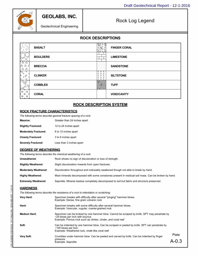
A-0.3
ROCK DESCRIPTIONS
Plate
BRECCIA
CLINKER
COBBLES
CORAL
BASALT
ROCK DESCRIPTION SYSTEM
Greater than 24 inches apart
12 to 24 inches apart
6 to 12 inches apart
3 to 6 inches apart
Less than 3 inches apart
Rock shows no sign of discoloration or loss of strength.
Slight discoloration inwards from open fractures.
Discoloration throughout and noticeably weakened though not able to break by hand.
Most minerals decomposed with some corestones present in residual soil mass. Can be broken by hand.
Saprolite. Mineral residue completely decomposed to soil but fabric and structure preserved.
The following terms describe general fracture spacing of a rock:
The following terms describe the chemical weathering of a rock:
ROCK FRACTURE CHARACTERISTICS
DEGREE OF WEATHERING
HARDNESS
BOULDERS
VOID/CAVITY
TUFF
SILTSTONE
LIMESTONE
FINGER CORAL
Unweathered:
Slightly Weathered:
Moderately Weathered:
Highly Weathered:
Extremely Weathered:
Very Hard:
Hard:
Medium Hard:
Soft:
Very Soft:
SANDSTONE
Massive:
Slightly Fractured:
Moderately Fractured:
Closely Fractured:
Severely Fractured:
Rock Log Legend
The following terms describe the resistance of a rock to indentation or scratching:
Specimen breaks with difficulty after several "pinging" hammer blows.Example: Dense, fine grain volcanic rock
Specimen breaks with some difficulty after several hammer blows.Example: Vesicular, vugular, coarse-grained rock
Specimen can be broked by one hammer blow. Cannot be scraped by knife. SPT may penetrate by~25 blows per inch with bounce.Example: Porous rock such as clinker, cinder, and coral reef
Can be indented by one hammer blow. Can be scraped or peeled by knife. SPT can penetrate by~100 blows per foot.Example: Weathered rock, chalk-like coral reef
Crumbles under hammer blow. Can be peeled and carved by knife. Can be indented by fingerpressure.Example: Saprolite
GEOLABS, INC.
Geotechnical Engineering
LOG
LE
GEN
D F
OR
RO
CK
741
7-00
(A).G
PJ
GE
OLA
BS.
GD
T 1
1/21
/16
Draft Geotechnical Report - 12-1-2016

37
2624
SM
SM
GW
32
25/5"Ref.20/0"Ref.
10092
57
90
100
100
67
Sieve- #200 =26.3%
1-inch ASPHALTIC CONCRETEBrown SILTY SAND (BASALTIC) with some
gravel, medium dense to dense, moist (fill)Gray COBBLY GRAVEL (BASALTIC),
subangular, dense, moist (colluvium)Brown with trace orange SILTY SAND
(BASALTIC) with some gravel, very dense,moist (older colluvium)
Brownish gray COBBLES (BASALTIC),subangular, dense, moist (older colluvium)
Grayish brown SANDY GRAVEL (BASALTIC)with traces of silt, very dense, moist (oldercolluvium)
Brownish gray to gray GRAVELLY COBBLES(BASALTIC) with some boulders and browncemented sand matrix, very dense, moist (oldercolluvium)
Boring terminated at 21 feet
* Elevations estimated from PreliminaryTopographic Survey Plan received from WilsonOkamoto Corporation on November 16, 2016.
Log ofBoring
Date Started:Date Completed:Logged By:Total Depth:Work Order:
Oth
er T
ests
Plate
Poc
ket P
en.
(tsf)
5
10
15
20
25
30
35
Gra
phic
Drill Rig:Drilling Method:Driving Energy:
Pen
etra
tion
Res
ista
nce
(blo
ws/
foot
)
Approximate Ground SurfaceElevation (feet ): 984.2 *
Sam
ple
Moi
stur
eC
onte
nt (%
)
1
Dry
Den
sity
(pcf
) Description
Laboratory
RQ
D (%
)
Cor
eR
ecov
ery
(%)
November 16, 2016November 17, 2016S. Latronic21 feet7417-00(A)
US
CS
Dep
th (f
eet)
Water Level:
Field
A - 1
GEOLABS, INC.
Geotechnical Engineering
IAO VALLEY STATE MONUMENT FLOOD REPAIRSJOB NO. J45CM41A
INTERIM REMEDIAL MEASURESWAILUKU, MAUI, HAWAII
BO
RIN
G_L
OG
741
7-00
(A).G
PJ
GE
OLA
BS.
GD
T 1
2/1/
16
Not Encountered
.Big Beaver4" Solid Stem Auger & NQ Coring140 lb. wt., 30 in. drop
Draft Geotechnical Report - 12-1-2016

14
8
3
SM5
20/0"Ref.
50/2"Ref.
10063
75
70
42
Sieve- #200 =18.4%
4-inch CONCRETE (BRIDGE DECK)SPACE BENEATH BRIDGE DECK
Brown SILTY SAND (BASALTIC) with somegravel, loose to medium dense, moist(colluvium)
Brownish gray to gray GRAVELLY COBBLES(BASALTIC) with some sand, dense to verydense, moist (older colluvium)
grades with boulders (basaltic)
grades more gravelly
Boring terminated at 28 feet
Log ofBoring
Date Started:Date Completed:Logged By:Total Depth:Work Order:
Oth
er T
ests
Plate
Poc
ket P
en.
(tsf)
5
10
15
20
25
30
35
Gra
phic
Drill Rig:Drilling Method:Driving Energy:
Pen
etra
tion
Res
ista
nce
(blo
ws/
foot
)
Approximate Ground SurfaceElevation (feet ): 976.2 *
Sam
ple
Moi
stur
eC
onte
nt (%
)
2
Dry
Den
sity
(pcf
) Description
Laboratory
RQ
D (%
)
Cor
eR
ecov
ery
(%)
November 17, 2016November 18, 2016S. Latronic28 feet7417-00(A)
US
CS
Dep
th (f
eet)
Water Level:
Field
A - 2
GEOLABS, INC.
Geotechnical Engineering
IAO VALLEY STATE MONUMENT FLOOD REPAIRSJOB NO. J45CM41A
INTERIM REMEDIAL MEASURESWAILUKU, MAUI, HAWAII
BO
RIN
G_L
OG
741
7-00
(A).G
PJ
GE
OLA
BS.
GD
T 1
2/1/
16
Not Encountered
Big Beaver4" Solid Stem Auger & NQ Coring140 lb. wt., 30 in. drop
.
Draft Geotechnical Report - 12-1-2016

115
17
GW
SM
41
50/1"Ref.
21
90
10010071
33
67
50
75
Sieve- #200 =18.5%
2-inch ASPHALTIC CONCRETEGrayish brown SANDY GRAVEL (BASALTIC)
with a little silt, dense, moist (fill)Brownish gray GRAVELLY COBBLES
(BASALTIC) with some silty sand, subrounded,dense, moist (older colluvium)
grades more sandy locally
Gray SILTY SAND (BASALTIC) with a littlegravel and traces of clay, medium dense, moist(older colluvium)
Gray GRAVELLY COBBLES (BASALTIC) withsome sand, subrounded, dense, moist (oldercolluvium)
grades more sand and gravel locally
grades with boulders (basaltic) Boring terminated at 19 feet
Log ofBoring
Date Started:Date Completed:Logged By:Total Depth:Work Order:
Oth
er T
ests
Plate
Poc
ket P
en.
(tsf)
5
10
15
20
25
30
35
Gra
phic
Drill Rig:Drilling Method:Driving Energy:
Pen
etra
tion
Res
ista
nce
(blo
ws/
foot
)
Approximate Ground SurfaceElevation (feet ): 983.5 *
Sam
ple
Moi
stur
eC
onte
nt (%
)
3
Dry
Den
sity
(pcf
) Description
Laboratory
RQ
D (%
)
Cor
eR
ecov
ery
(%)
November 15, 2016November 16, 2016S. Latronic19 feet7417-00(A)
US
CS
Dep
th (f
eet)
Water Level:
Field
A - 3
GEOLABS, INC.
Geotechnical Engineering
IAO VALLEY STATE MONUMENT FLOOD REPAIRSJOB NO. J45CM41A
INTERIM REMEDIAL MEASURESWAILUKU, MAUI, HAWAII
BO
RIN
G_L
OG
741
7-00
(A).G
PJ
GE
OLA
BS.
GD
T 1
2/1/
16
Not Encountered
Big Beaver4" Solid Stem Auger & NQ Coring140 lb. wt., 30 in. drop
.
Draft Geotechnical Report - 12-1-2016

20
13
3
6
4
7
100
118
SM9/6"
+50/5"15/0"
7
20/0" Ref.
22/6" +30/5"
25
10/0" Ref.
25/1"
77
83
72
33
64
32
47
4-inches ASPHALTIC CONCRETEBrown SILTY SAND with some gravel, medium
dense, moist (fill)Brownish gray angular COBBLY BOULDERS
(BASALTIC) with some angular to subangulargravel and silty sand, very dense, moist(overcast fill)
Log ofBoring
Date Started:Date Completed:Logged By:Total Depth:Work Order:
Oth
er T
ests
Plate
Poc
ket P
en.
(tsf)
CME-75DG14" Solid Stem Auger & PQ Coring140 lb. wt., 30 in. drop
5
10
15
20
25
30
35
Gra
phic
Drill Rig:Drilling Method:Driving Energy:
Pen
etra
tion
Res
ista
nce
(blo
ws/
foot
)
Approximate Ground SurfaceElevation (feet ): 965.5 *
Sam
ple
Moi
stur
eC
onte
nt (%
)
4
Dry
Den
sity
(pcf
) Description
Laboratory
RQ
D (%
)
Cor
eR
ecov
ery
(%)
November 7, 2016November 9, 2016B. Aiu80.17 feet7417-00(A)
US
CS
Dep
th (f
eet)
Water Level:
Field
A - 4.1(Energy Transfer Ratio = 80.3%)
GEOLABS, INC.
Geotechnical Engineering
IAO VALLEY STATE MONUMENT FLOOD REPAIRSJOB NO. J45CM41A
INTERIM REMEDIAL MEASURESWAILUKU, MAUI, HAWAII
BO
RIN
G_L
OG
741
7-00
(A).G
PJ
GE
OLA
BS.
GD
T 1
2/1/
16
62.0 ft. 11/09/2016 1139 HRS
Draft Geotechnical Report - 12-1-2016

10
8
8
17
51
45/6" +10/0" Ref.
37
15/0" Ref.
23
40/6" +35/2"
15/0" Ref.
71
25
71
50
60
74
48
Brownish gray subangular COBBLY BOULDERS(BASALTIC) with some clayey sand andsubrounded gravel, very dense, wet (oldercolluvium)
Gray subrounded COBBLY BOULDERS(BASALTIC) with some clayey sand andsubrounded gravel, very dense (older colluvium)
Log ofBoring
Date Started:Date Completed:Logged By:Total Depth:Work Order:
Oth
er T
ests
Plate
Poc
ket P
en.
(tsf)
CME-75DG14" Solid Stem Auger & PQ Coring140 lb. wt., 30 in. drop
40
45
50
55
60
65
70
Gra
phic
Drill Rig:Drilling Method:Driving Energy:
Pen
etra
tion
Res
ista
nce
(blo
ws/
foot
)
Sam
ple
Moi
stur
eC
onte
nt (%
)
4
Dry
Den
sity
(pcf
) Description
Laboratory
RQ
D (%
)
Cor
eR
ecov
ery
(%)
(Continued from previous plate)
November 7, 2016November 9, 2016B. Aiu80.17 feet7417-00(A)
US
CS
Dep
th (f
eet)
Water Level:
Field
A - 4.2(Energy Transfer Ratio = 80.3%)
GEOLABS, INC.
Geotechnical Engineering
IAO VALLEY STATE MONUMENT FLOOD REPAIRSJOB NO. J45CM41A
INTERIM REMEDIAL MEASURESWAILUKU, MAUI, HAWAII
BO
RIN
G_L
OG
741
7-00
(A).G
PJ
GE
OLA
BS.
GD
T 1
2/1/
16
62.0 ft. 11/09/2016 1139 HRS
Draft Geotechnical Report - 12-1-2016

10 61
15/0" Ref.
35/2"
69
42
Boring terminated at 80.17 feet
Log ofBoring
Date Started:Date Completed:Logged By:Total Depth:Work Order:
Oth
er T
ests
Plate
Poc
ket P
en.
(tsf)
CME-75DG14" Solid Stem Auger & PQ Coring140 lb. wt., 30 in. drop
75
80
85
90
95
100
105
Gra
phic
Drill Rig:Drilling Method:Driving Energy:
Pen
etra
tion
Res
ista
nce
(blo
ws/
foot
)
Sam
ple
Moi
stur
eC
onte
nt (%
)
4
Dry
Den
sity
(pcf
) Description
Laboratory
RQ
D (%
)
Cor
eR
ecov
ery
(%)
(Continued from previous plate)
November 7, 2016November 9, 2016B. Aiu80.17 feet7417-00(A)
US
CS
Dep
th (f
eet)
Water Level:
Field
A - 4.3(Energy Transfer Ratio = 80.3%)
GEOLABS, INC.
Geotechnical Engineering
IAO VALLEY STATE MONUMENT FLOOD REPAIRSJOB NO. J45CM41A
INTERIM REMEDIAL MEASURESWAILUKU, MAUI, HAWAII
BO
RIN
G_L
OG
741
7-00
(A).G
PJ
GE
OLA
BS.
GD
T 1
2/1/
16
62.0 ft. 11/09/2016 1139 HRS
Draft Geotechnical Report - 12-1-2016

18
9
14
10
11
97
108
101
SM26
32
83
15/0" Ref.
15/0" Ref.
14/6" +15/0" Ref.
11/6" +40/3"
75
33
67
37
40
45
36
3-inches ASPHALTIC CONCRETEBrown SILTY SAND with some gravel, medium
dense, moist (fill)Brownish gray angular COBBLY BOULDERS
(BASALTIC) with some angular to subangulargravel and silty sand, very dense, moist(overcast fill)
Log ofBoring
Date Started:Date Completed:Logged By:Total Depth:Work Order:
Oth
er T
ests
Plate
Poc
ket P
en.
(tsf)
CME-75DG14" Solid Stem Auger & PQ Coring140 lb. wt., 30 in. drop
5
10
15
20
25
30
35
Gra
phic
Drill Rig:Drilling Method:Driving Energy:
Pen
etra
tion
Res
ista
nce
(blo
ws/
foot
)
Approximate Ground SurfaceElevation (feet ): 958.8 *
Sam
ple
Moi
stur
eC
onte
nt (%
)
5
Dry
Den
sity
(pcf
) Description
Laboratory
RQ
D (%
)
Cor
eR
ecov
ery
(%)
November 9, 2016November 11, 2016B. Aiu81.5 feet7417-00(A)
US
CS
Dep
th (f
eet)
Water Level:
Field
A - 5.1(Energy Transfer Ratio = 80.3%)
GEOLABS, INC.
Geotechnical Engineering
IAO VALLEY STATE MONUMENT FLOOD REPAIRSJOB NO. J45CM41A
INTERIM REMEDIAL MEASURESWAILUKU, MAUI, HAWAII
BO
RIN
G_L
OG
741
7-00
(A).G
PJ
GE
OLA
BS.
GD
T 1
2/1/
16
54.8 ft. 11/11/2016 1236 HRS
Draft Geotechnical Report - 12-1-2016

9
4
18
18
121 37/6" +25/3"
30/5"
10/0" Ref.
40
15/0" Ref.
15/0" Ref.
15/0" Ref.
62
70
27
86
42
72
67
Brown and gray subangular COBBLYBOULDERS (BASALTIC) with some silty sandand subangular to subrounded gravel, verydense, wet (older colluvium)
Log ofBoring
Date Started:Date Completed:Logged By:Total Depth:Work Order:
Oth
er T
ests
Plate
Poc
ket P
en.
(tsf)
CME-75DG14" Solid Stem Auger & PQ Coring140 lb. wt., 30 in. drop
40
45
50
55
60
65
70
Gra
phic
Drill Rig:Drilling Method:Driving Energy:
Pen
etra
tion
Res
ista
nce
(blo
ws/
foot
)
Sam
ple
Moi
stur
eC
onte
nt (%
)
5
Dry
Den
sity
(pcf
) Description
Laboratory
RQ
D (%
)
Cor
eR
ecov
ery
(%)
(Continued from previous plate)
November 9, 2016November 11, 2016B. Aiu81.5 feet7417-00(A)
US
CS
Dep
th (f
eet)
Water Level:
Field
A - 5.2(Energy Transfer Ratio = 80.3%)
GEOLABS, INC.
Geotechnical Engineering
IAO VALLEY STATE MONUMENT FLOOD REPAIRSJOB NO. J45CM41A
INTERIM REMEDIAL MEASURESWAILUKU, MAUI, HAWAII
BO
RIN
G_L
OG
741
7-00
(A).G
PJ
GE
OLA
BS.
GD
T 1
2/1/
16
54.8 ft. 11/11/2016 1236 HRS
Draft Geotechnical Report - 12-1-2016

10/0" Ref.
10/0" Ref.
43
60
70
Brown and gray subrounded COBBLYBOULDERS (BASALTIC) with some clayeysand and subrounded to rounded gravel, verydense (older colluvium)
Boring terminated at 81.5 feet
Log ofBoring
Date Started:Date Completed:Logged By:Total Depth:Work Order:
Oth
er T
ests
Plate
Poc
ket P
en.
(tsf)
CME-75DG14" Solid Stem Auger & PQ Coring140 lb. wt., 30 in. drop
75
80
85
90
95
100
105
Gra
phic
Drill Rig:Drilling Method:Driving Energy:
Pen
etra
tion
Res
ista
nce
(blo
ws/
foot
)
Sam
ple
Moi
stur
eC
onte
nt (%
)
5
Dry
Den
sity
(pcf
) Description
Laboratory
RQ
D (%
)
Cor
eR
ecov
ery
(%)
(Continued from previous plate)
November 9, 2016November 11, 2016B. Aiu81.5 feet7417-00(A)
US
CS
Dep
th (f
eet)
Water Level:
Field
A - 5.3(Energy Transfer Ratio = 80.3%)
GEOLABS, INC.
Geotechnical Engineering
IAO VALLEY STATE MONUMENT FLOOD REPAIRSJOB NO. J45CM41A
INTERIM REMEDIAL MEASURESWAILUKU, MAUI, HAWAII
BO
RIN
G_L
OG
741
7-00
(A).G
PJ
GE
OLA
BS.
GD
T 1
2/1/
16
54.8 ft. 11/11/2016 1236 HRS
Draft Geotechnical Report - 12-1-2016

13
100
12
10
3
113 107
16/6" +15/0" Ref.10/0" Ref.
29
15/0" Ref.
20/1"
16
15/0" Ref.
82
52
63
51
69
70
4-inches ASPHALTIC CONCRETEBrownish gray angular COBBLY BOULDERS
(BASALTIC) with some angular to subangulargravel and silty sand, very dense, moist(overcast fill)
Brown and gray subangular COBBLYBOULDERS (BASALTIC) with some silty sandand subangular to subrounded gravel, verydense, wet (older colluvium)
Log ofBoring
Date Started:Date Completed:Logged By:Total Depth:Work Order:
Oth
er T
ests
Plate
Poc
ket P
en.
(tsf)
CME-75DG14" Solid Stem Auger & PQ Coring140 lb. wt., 30 in. drop
5
10
15
20
25
30
35
Gra
phic
Drill Rig:Drilling Method:Driving Energy:
Pen
etra
tion
Res
ista
nce
(blo
ws/
foot
)
Approximate Ground SurfaceElevation (feet ): 949.5 *
Sam
ple
Moi
stur
eC
onte
nt (%
)
6
Dry
Den
sity
(pcf
) Description
Laboratory
RQ
D (%
)
Cor
eR
ecov
ery
(%)
November 14, 2016November 15, 2016B. Aiu80.5 feet7417-00(A)
US
CS
Dep
th (f
eet)
Water Level:
Field
A - 6.1(Energy Transfer Ratio = 80.3%)
GEOLABS, INC.
Geotechnical Engineering
IAO VALLEY STATE MONUMENT FLOOD REPAIRSJOB NO. J45CM41A
INTERIM REMEDIAL MEASURESWAILUKU, MAUI, HAWAII
BO
RIN
G_L
OG
741
7-00
(A).G
PJ
GE
OLA
BS.
GD
T 1
2/1/
16
51.0 ft. 11/17/2016 1542 HRS
Draft Geotechnical Report - 12-1-2016

8
7
27
16
31
114
83
30/5"
49
30
26
15/0" Ref.
15/0" Ref.
50
49
81
17
45
33
28
43
Brown and gray subrounded COBBLYBOULDERS (BASALTIC) with some clayeysand and subrounded to rounded gravel, verydense (older colluvium)
Log ofBoring
Date Started:Date Completed:Logged By:Total Depth:Work Order:
Oth
er T
ests
Plate
Poc
ket P
en.
(tsf)
CME-75DG14" Solid Stem Auger & PQ Coring140 lb. wt., 30 in. drop
40
45
50
55
60
65
70
Gra
phic
Drill Rig:Drilling Method:Driving Energy:
Pen
etra
tion
Res
ista
nce
(blo
ws/
foot
)
Sam
ple
Moi
stur
eC
onte
nt (%
)
6
Dry
Den
sity
(pcf
) Description
Laboratory
RQ
D (%
)
Cor
eR
ecov
ery
(%)
(Continued from previous plate)
November 14, 2016November 15, 2016B. Aiu80.5 feet7417-00(A)
US
CS
Dep
th (f
eet)
Water Level:
Field
A - 6.2(Energy Transfer Ratio = 80.3%)
GEOLABS, INC.
Geotechnical Engineering
IAO VALLEY STATE MONUMENT FLOOD REPAIRSJOB NO. J45CM41A
INTERIM REMEDIAL MEASURESWAILUKU, MAUI, HAWAII
BO
RIN
G_L
OG
741
7-00
(A).G
PJ
GE
OLA
BS.
GD
T 1
2/1/
16
51.0 ft. 11/17/2016 1542 HRS
Draft Geotechnical Report - 12-1-2016

14
38
15/0" Ref.
30/3"
20/0" Ref.
77
60
Boring terminated at 80.5 feet
Log ofBoring
Date Started:Date Completed:Logged By:Total Depth:Work Order:
Oth
er T
ests
Plate
Poc
ket P
en.
(tsf)
CME-75DG14" Solid Stem Auger & PQ Coring140 lb. wt., 30 in. drop
75
80
85
90
95
100
105
Gra
phic
Drill Rig:Drilling Method:Driving Energy:
Pen
etra
tion
Res
ista
nce
(blo
ws/
foot
)
Sam
ple
Moi
stur
eC
onte
nt (%
)
6
Dry
Den
sity
(pcf
) Description
Laboratory
RQ
D (%
)
Cor
eR
ecov
ery
(%)
(Continued from previous plate)
November 14, 2016November 15, 2016B. Aiu80.5 feet7417-00(A)
US
CS
Dep
th (f
eet)
Water Level:
Field
A - 6.3(Energy Transfer Ratio = 80.3%)
GEOLABS, INC.
Geotechnical Engineering
IAO VALLEY STATE MONUMENT FLOOD REPAIRSJOB NO. J45CM41A
INTERIM REMEDIAL MEASURESWAILUKU, MAUI, HAWAII
BO
RIN
G_L
OG
741
7-00
(A).G
PJ
GE
OLA
BS.
GD
T 1
2/1/
16
51.0 ft. 11/17/2016 1542 HRS
Draft Geotechnical Report - 12-1-2016

Draft Geotechnical Report - 12-1-2016

W.O. 7417-00(A) GEOLABS, INC. DECEMBER 2016 Page B-1
Hawaii • California
A P P E N D I X B
Laboratory Tests
Laboratory tests were not completed at the time this draft report was prepared. Laboratory test results will be included in the final report for the project.
Moisture Content (ASTM D2216) and Unit Weight (ASTM D2937) determinations were performed on selected samples as an aid in the classification and evaluation of soil properties. The test results are presented on the Logs of Borings at the appropriate sample depths.
Three Sieve Analysis tests (ASTM C117 & C136) including four hydrometer tests [ASTM D422-63(2007)e2] were performed on selected soil samples to evaluate the gradation characteristics of the soils and to aid in soil classification. Graphic presentation of the grain size distributions is provided on Plate B-1.
Draft Geotechnical Report - 12-1-2016

0
5
10
15
20
25
30
35
40
45
50
55
60
65
70
75
80
85
90
95
100
0.0010.010.1110100
3/8
HYDROMETER
3
GRAIN SIZE IN MILLIMETERS
PE
RC
EN
T FI
NE
R B
Y W
EIG
HT
100
coarse
1/2
Sample
0.1020.2360.373
0.5832.0454.551
B - 1
PILL PL
coarse
11.53 2 40
Depth (ft)
%Gravel15.623.439.3
58.158.242.2
%Sand
COBBLES
Sample D30 (mm)
14020
Description Cu
GRAVEL
U.S. SIEVE NUMBERS
D10 (mm)
Brown silty sand (SM) with some gravelBrown silty sand (SM) with some gravelGray silty sand (SM) with some gravel
16
fine
37.51925
Cc
3/4
fineSILT OR CLAY
medium
GRAIN SIZE DISTRIBUTION - ASTM C117 & C136
SAND
%Fine
604 30 20046
26.318.418.5
Depth (ft)
810 14 50
U.S. SIEVE OPENING IN INCHES
6
D60 (mm)D100 (mm)B-1B-2B-3
1.5-2.58.5-10.5
10.0-11.5
1.5-2.58.5-10.5
10.0-11.5
B-1B-2B-3
Plate
W.O. 7417-00(A)
GEOTECHNICAL ENGINEERING
GEOLABS, INC.IAO VALLEY STATE MONUMENT FLOOD REPAIRS
JOB NO. J45CM41AINTERIM REMEDIAL MEASURES
WAILUKU, MAUI, HAWAII
G_G
RAI
N_S
IZE
741
7-00
(A).G
PJ
GE
OLA
BS.
GD
T 1
2/1/
16
Draft Geotechnical Report - 12-1-2016

Draft Geotechnical Report - 12-1-2016

Iao Valley State Monument Flood Repairs Job No. J45CM41A, Interim Remedial Measures Wailuku, Maui, Hawaii
W.O. 7417‐00(A) GEOLABS, INC. PLATE C‐1 Hawaii • California
B‐1 5.75’ TO 21.0’
Draft Geotechnical Report - 12-1-2016

Iao Valley State Monument Flood Repairs Job No. J45CM41A, Interim Remedial Measures Wailuku, Maui, Hawaii
W.O. 7417‐00(A) GEOLABS, INC. PLATE C‐2 Hawaii • California
B‐2 11.0’ TO 28.0’
Draft Geotechnical Report - 12-1-2016

Iao Valley State Monument Flood Repairs Job No. J45CM41A, Interim Remedial Measures Wailuku, Maui, Hawaii
W.O. 7417‐00(A) GEOLABS, INC. PLATE C‐3 Hawaii • California
B‐3 0.8’ TO 19.0’
Draft Geotechnical Report - 12-1-2016

Iao Valley State Monument Flood Repairs Job No. J45CM41A, Interim Remedial Measures Wailuku, Maui, Hawaii
W.O. 7417‐00(A) GEOLABS, INC. PLATE C‐4 Hawaii • California
B‐4 2.5’ TO 65.0’
Draft Geotechnical Report - 12-1-2016

Iao Valley State Monument Flood Repairs Job No. J45CM41A, Interim Remedial Measures Wailuku, Maui, Hawaii
W.O. 7417‐00(A) GEOLABS, INC. PLATE C‐5 Hawaii • California
B‐4 65.0’ TO 80.0’
Draft Geotechnical Report - 12-1-2016

Iao Valley State Monument Flood Repairs Job No. J45CM41A, Interim Remedial Measures Wailuku, Maui, Hawaii
W.O. 7417‐00(A) GEOLABS, INC. PLATE C‐6 Hawaii • California
B‐5 6.5’ TO 60.0’
Draft Geotechnical Report - 12-1-2016

Iao Valley State Monument Flood Repairs Job No. J45CM41A, Interim Remedial Measures Wailuku, Maui, Hawaii
W.O. 7417‐00(A) GEOLABS, INC. PLATE C‐7 Hawaii • California
B‐5 60.0’ TO 80.0’
Draft Geotechnical Report - 12-1-2016

Iao Valley State Monument Flood Repairs Job No. J45CM41A, Interim Remedial Measures Wailuku, Maui, Hawaii
W.O. 7417‐00(A) GEOLABS, INC. PLATE C‐8 Hawaii • California
B‐6 5.0’ TO 60.0’
Draft Geotechnical Report - 12-1-2016

Iao Valley State Monument Flood Repairs Job No. J45CM41A, Interim Remedial Measures Wailuku, Maui, Hawaii
W.O. 7417‐00(A) GEOLABS, INC. PLATE C‐9 Hawaii • California
B‐6 70.0’ TO 80.0’
Draft Geotechnical Report - 12-1-2016
Top Related