


Languages
Pages
Legal


Generic Quick Coupler Lock Kit Installation Instructions
For Pilot Operated Loaders
(24V System)
Technical Support Hotline (800) 537-9561
TABLE OF CONTENTS
GENERAL SAFETY GUIDELINES FOR INSTALLING THE KIT ................................3
BEFORE STARTING THE KIT INSTALLATION ...........................................................4
JIC 37° FLARE CONNECTIONS.......................................................................................5
ORING FACE SEAL CONNECTIONS..............................................................................6
STANDARD TIGHTENING TORQUE .............................................................................7
PRECAUTIONS BEFORE WELDING ..............................................................................8
SYSTEM OVERVIEW........................................................................................................9
LOADER HOSES ..............................................................................................................10
CONTROL VALVE ..........................................................................................................11
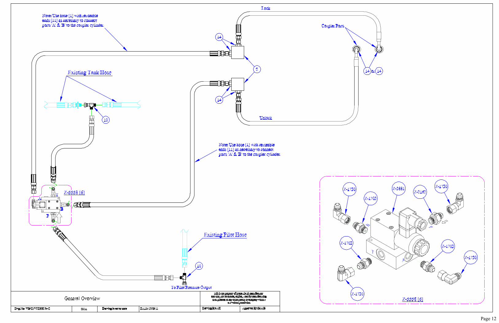
General Overview Drawing ...........................................................................................12
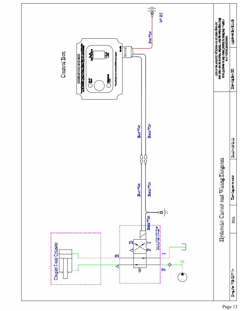
Hydraulic Schematic and Electrical Wiring Diagram....................................................13
FINISH AND TEST...........................................................................................................14
BILL OF MATERIALS.....................................................................................................15
APPENDIX A ....................................................................................................................17
APPENDIX B – REUSABLE HOSE AND HOSE ENDS................................................19
CUSTOMER FEEDBACK FORM....................................................................................20
Total Number of Pages 20
Page 2
GENERAL SAFETY GUIDELINES FOR INSTALLING THE KIT • Read the instruction manual thoroughly to familiarize yourself with the kit before
installing it. Deviating from the drawings and/or instructions in this manual may result in increased installation time and/or damage to hydraulic kit, machine or attachment.
• Follow proper procedures as specified in the ‘Service Manual’ for your machine. In case of discrepancies in guidelines between the ‘Service Manual’ and our kit instructions, the manufacturer safety instructions take precedence, especially regarding the welding instructions.
• Use safety protection such as hardhat; working gloves, safety shoes and safety glasses as needed to do the job.
• Lower the bucket or any attachment to the ground. • It is very important to relieve the hydraulic tank pressure before loosening any
connections or hoses. Follow proper procedures as specified in the ‘Service Manual’ for your machine.
• Be careful while handling hot parts on machines that have just been shut down. The hydraulic fluid in the lines, tubes and components are very hot and could cause severe skin burns. It is advisable to allow hydraulic oil to cool down before removing any lines, fittings, tubes or plugs on machines.
• Kit installation procedures outlined in this instruction manual have been arranged to keep the hydraulic oil spills to a minimum. However, during kit installation, oil spills are unavoidable and should be contained using rags, absorbent towels or containers/buckets. Dispose of all waste oils, fluids, lubricants and other hazardous waste properly. If there is an oil spill on the floor, use liberal amounts of “oil dry” to avoid slippery conditions.
• Once installation in complete, check and tighten all fittings and hoses before activating the circuit.
• Use a piece of cardboard to check for oil leaks in the circuit, in order to prevent contact with high-pressure oil.
Page 3
BEFORE STARTING THE KIT INSTALLATION • Check to make sure this installation kit is correct for your excavator and/or
attachment. Check the excavator information against kit description. If there are any concerns or discrepancies please contact the kit manufacturer immediately.
• Open crates/boxes to take inventory of parts. Compare them with the Bill of Materials to make sure no parts are missing. Please note that to reduce installation time, some components are pre-assembled before shipping. In case of any discrepancies, contact kit manufacturer immediately.
• Read instructions manual to familiarize yourself with the installation kit. • For the purpose of kit installation, it is a safe practice to have the machine on a level
surface. Swing the machine housing to get access to the panels under the cab for installing the pilot circuit components. It will be necessary to remove the panels under the cab for this purpose.
• Shut off engine. If the machine has just completed work then allow sufficient time for cooling before opening any lines.
• Make sure there are enough rags, absorbent towels and/or containers available. • Disconnect battery. Remove the negative (ground) terminal connection. • Release pressure from the hydraulic tank. • Flow meter and pressure gauges will be required to complete the Finish and Test
section of this installation. • Steel brackets/mounts are protected from corrosion using primer or optional powder
coating. It may be necessary to paint these to match the excavator color after completing installation and checking all hoses for binding/pinching. Ensure there is enough factory paint available to do so.
• Refer to the following pages for the proper specifications for all connections. These specs must be followed to prevent damage to the threads and flare seat.
Page 4
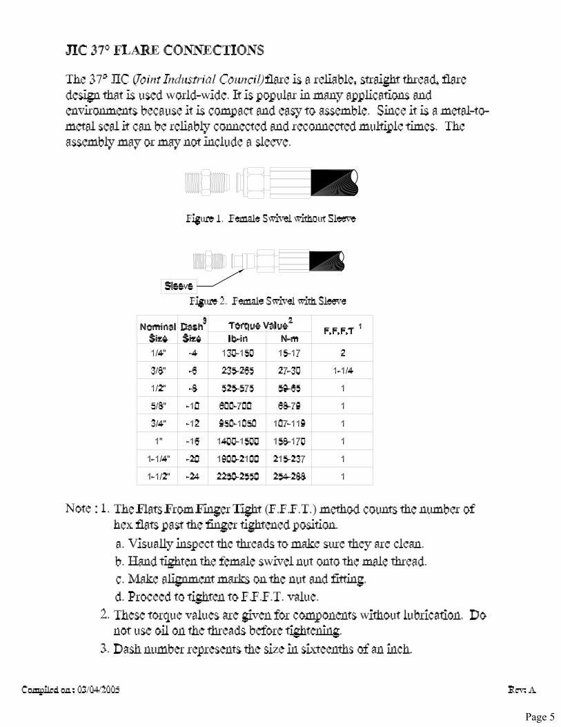
Page 5
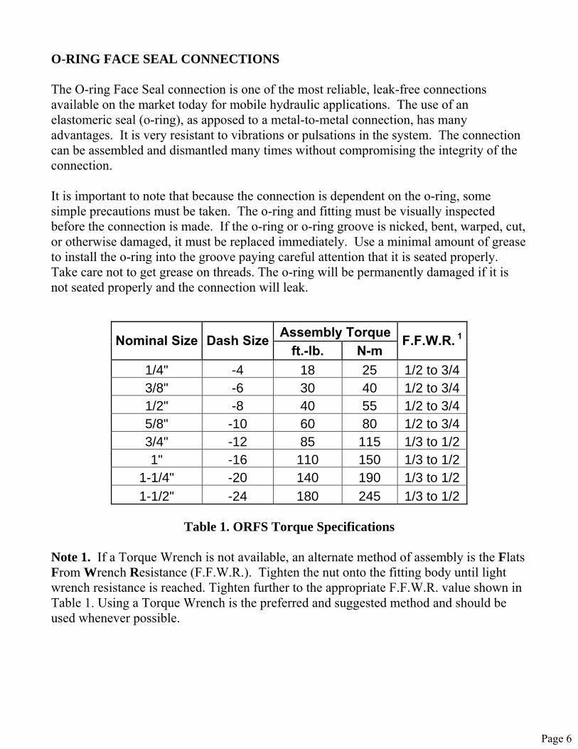
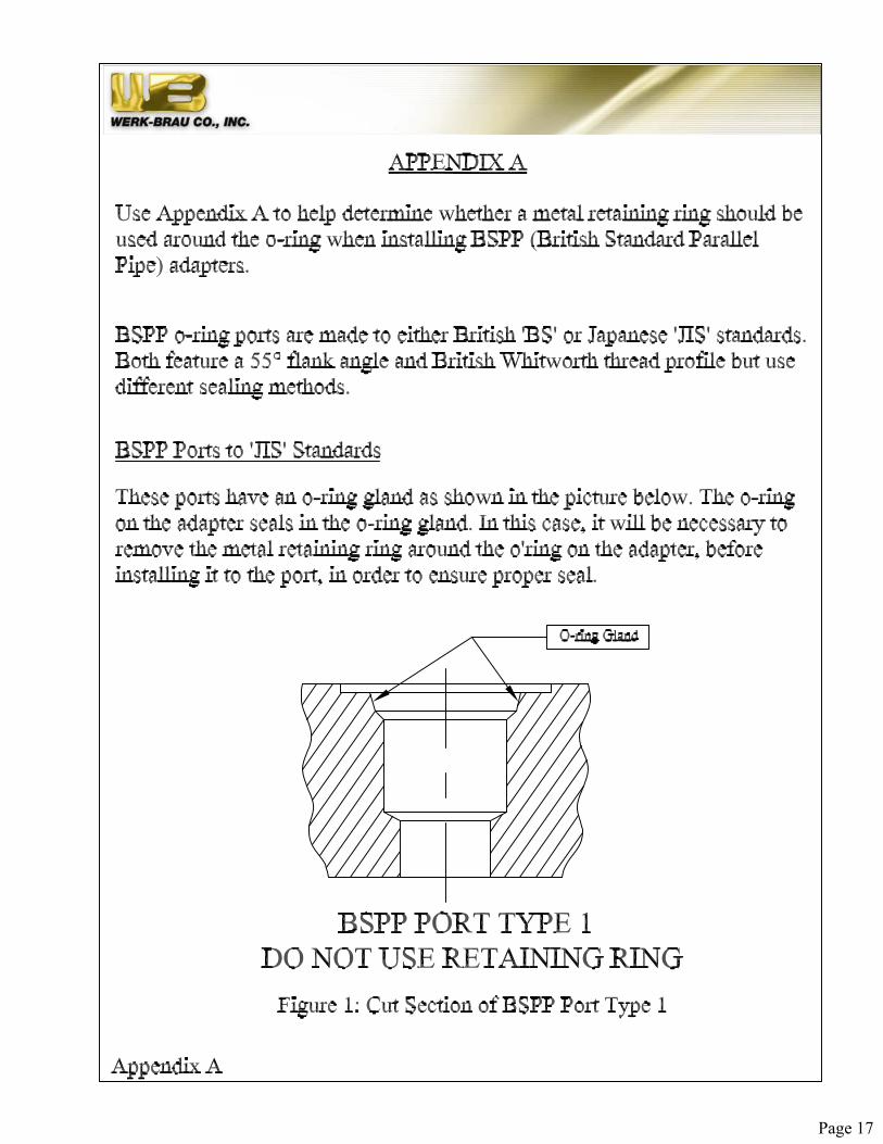
O-RING FACE SEAL CONNECTIONS The O-ring Face Seal connection is one of the most reliable, leak-free connections available on the market today for mobile hydraulic applications. The use of an elastomeric seal (o-ring), as apposed to a metal-to-metal connection, has many advantages. It is very resistant to vibrations or pulsations in the system. The connection can be assembled and dismantled many times without compromising the integrity of the connection. It is important to note that because the connection is dependent on the o-ring, some simple precautions must be taken. The o-ring and fitting must be visually inspected before the connection is made. If the o-ring or o-ring groove is nicked, bent, warped, cut, or otherwise damaged, it must be replaced immediately. Use a minimal amount of grease to install the o-ring into the groove paying careful attention that it is seated properly. Take care not to get grease on threads. The o-ring will be permanently damaged if it is not seated properly and the connection will leak.
Assembly TorqueNominal Size Dash Sizeft.-lb. N-m
F.F.W.R. 1
1/4" -4 18 25 1/2 to 3/4 3/8" -6 30 40 1/2 to 3/4 1/2" -8 40 55 1/2 to 3/4 5/8" -10 60 80 1/2 to 3/4 3/4" -12 85 115 1/3 to 1/2 1" -16 110 150 1/3 to 1/2
1-1/4" -20 140 190 1/3 to 1/2 1-1/2" -24 180 245 1/3 to 1/2
Table 1. ORFS Torque Specifications
Note 1. If a Torque Wrench is not available, an alternate method of assembly is the Flats From Wrench Resistance (F.F.W.R.). Tighten the nut onto the fitting body until light wrench resistance is reached. Tighten further to the appropriate F.F.W.R. value shown in Table 1. Using a Torque Wrench is the preferred and suggested method and should be used whenever possible.
Page 6

STANDARD TIGHTENING TORQUE The following Table gives the standard tightening torques of bolts. This applies to mounts, tube clamps, split flange clamps, and any other bolts provided with this kit. It is important to follow this chart when installing bolts and nuts. Failure to do so could result in premature failure, damage to components, or even serious injury. NOTE: Nm (Newton meter): 1Nm = 0.102 kgm = 0.737 lb.ft.
Standard Tightening Torque Of Metric Bolts
Metric Class 10.9 Bolt O.D. x Pitch (mm)
kgm Nm lb.ft.
M6x1 1.3 +/- 0.15 13.5 +/- 1.5 10 +/- 1 M8x1.25 3.2 +/- 0.3 32.2 +/- 3.5 24 +/- 2.6 M10x1.5 6.5 +/- 0.6 63 +/- 6.5 47 +/- 4.8
M12x1.75 11 +/- 1 108 +/- 11 80 +/- 8 M14x2 17.5 +/- 2 172 +/- 18 127 +/- 13 M16x2 27 +/- 3 268 +/- 29 198 +/- 22
M18x2.5 37 +/- 4 366 +/- 36 270 +/- 26
Page 7
PRECAUTIONS BEFORE WELDING • NOTE: These techniques are a general guideline only. If the excavator manufacturer
has published welding guidelines, use them instead. • Turn off the engine and disconnect the battery. • Protect all areas in, on and around the machine with a flame resistant covering during
grinding and welding operations. Use proper solvents to clean parts for welding. Always clean parts in a well-ventilated area. Cover the cylinder rods and glass for protection against welding spatter. Protect any wiring harnesses in the vicinity.
• Clean welding areas of any combustible materials like dried leaves, hydraulic oil etc. • Clamp the ground cable from the welder, directly to the component that will be
welded. If this is not achievable, place the clamp as close as possible to the weld. Make sure the electrical path from the ground cable to the component does not go through a bearing.
Page 8
SYSTEM OVERVIEW • This instruction manual describes the installation of the hydraulic kit that will operate
the Werk-Brau coupler on a pilot operated Loader. This hydraulic circuit uses pilot pressure (500-600psi) to lock and unlock the coupler.
• The coupler attaches onto various tools by “hooking” the front pin and then rotating a locking device under the rear pin of the attachment. The lock is self-adjusting, so no adjustments are needed. While engaged, the lock is securely held in place by the cylinder and dual extension springs. In the event of hydraulic failure, the coupler’s safety lock will enable the coupler to hold the attachment.
• To disengage (unlock) the coupler, position the machine as described in the “Operation and Maintenance” manual, also supplied with this coupler. Remove the safety pin and turn the toggle switch in the “unlock” position. Follow the steps to safely remove the attachment.
• With the toggle switch still in the “unlock” position, position the machine to pick up the next attachment. Follow the steps to safely connect to the new attachment. Turn the switch to the “lock” position and wait several seconds for the lock to fully engage. Now install the safety lock pin with lynch pin in the rear of the coupler to fully lock the attachment in place.
• THE SAFETY LOCK PIN MUST BE INSTALLED AT ALL TIMES DURING USE OF THE COUPLER. Failure to install the safety pin could result in severe injury or death. Once installed, it insures the operator that the lock is properly seated under the pin, because the safety pin lock cannot be installed if the lock is only partially engaged. The Safety Lock Pin will also prohibit inadvertent disengagement.
• Before operating a machine with a Werk Brau coupler, visually check that the lock is properly positioned with the rear pin and the safety lock pin is properly installed.
• To confirm that the coupler and attachment are properly connected, set the attachment on the ground and rotate in a dumping motion until the tracks come off the ground. Do this EVERY time an attachment is changed.
• Never lift an attachment off the ground until all steps have been completed to confirm safe and proper connection.
• NOTE: Pictures and diagrams throughout this manual may not be your exact Werk-Brau coupler. The pictures represent an action or a setup required for installation and operation.
Page 9
LOADER HOSES • Install the straight adapters [14 or 4] and 90deg swivel [12] if required, to the ports on
the coupler lock cylinder. • Measure the required length of hose [1] to reach from the cylinder fittings to the
loader arms. There will be blocks [2] with adapters [14] welded to the loader arms to act as a junction block and support for the hoses. The block location should be determined by moving the arms throughout the full range of motion. Watch the hoses curl and fall and then use the blocks to support and route the hoses to keep them out of harms way. Use reusable hose ends [11] with cut length of hose. Refer to Appendix B for details on hose assembly.
• This may require adjustments so clamp or tack weld the blocks [2] in place. Do not finish weld until all hoses have been checked for pinching or binding.
• Leave a small amount of slack in the hoses to allow for cylinder movement while locking and unlocking.
• The remaining hoses connections will use the hose [1] with reusable hoses ends [11]. • Measure the required length of hose to reach from the blocks to the valve mounting
location (near pilot pump) as described in the next section of this manual. • Connect the hoses to the blocks and route them up the loader arms. Be sure to allow
enough hose in the pivot areas of the machine. Use the hose clamps [9] and wire ties [8] to secure the hoses to the machine, existing blocks, tubes and hoses.
• If using the clamps [9] first tack weld the bases in place. Once the location is finalized, remove the hoses and finish weld the bases.
• Install hoses and check for correct alignment and routing. Operate the machine and observe hose movement throughout the whole range of motion of the loader arms. There must be no binding or strain in any of the hoses. Make adjustments as necessary.
Page 10
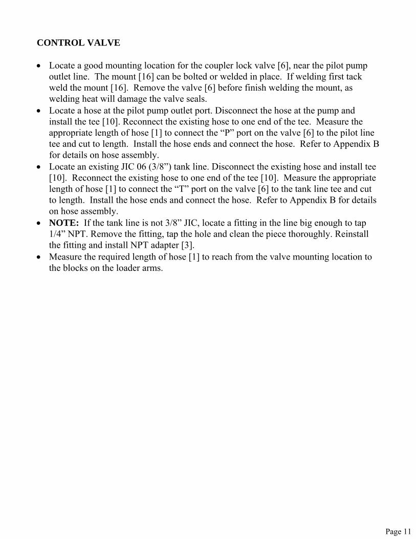
CONTROL VALVE • Locate a good mounting location for the coupler lock valve [6], near the pilot pump
outlet line. The mount [16] can be bolted or welded in place. If welding first tack weld the mount [16]. Remove the valve [6] before finish welding the mount, as welding heat will damage the valve seals.
• Locate a hose at the pilot pump outlet port. Disconnect the hose at the pump and install the tee [10]. Reconnect the existing hose to one end of the tee. Measure the appropriate length of hose [1] to connect the “P” port on the valve [6] to the pilot line tee and cut to length. Install the hose ends and connect the hose. Refer to Appendix B for details on hose assembly.
• Locate an existing JIC 06 (3/8”) tank line. Disconnect the existing hose and install tee [10]. Reconnect the existing hose to one end of the tee [10]. Measure the appropriate length of hose [1] to connect the “T” port on the valve [6] to the tank line tee and cut to length. Install the hose ends and connect the hose. Refer to Appendix B for details on hose assembly.
• NOTE: If the tank line is not 3/8” JIC, locate a fitting in the line big enough to tap 1/4” NPT. Remove the fitting, tap the hole and clean the piece thoroughly. Reinstall the fitting and install NPT adapter [3].
• Measure the required length of hose [1] to reach from the valve mounting location to the blocks on the loader arms.
Page 11
Page 12
Page 13
FINISH AND TEST • Before starting this section, position the machine in the oil level check position as
suggested by the loader manufacturer. Check the oil level sight gauge on the hydraulic tank to ensure that the machine has enough hydraulic oil. Add hydraulic oil (use only loader manufacturer recommended grade) if necessary.
• Check again for proper hose movement and routing, then tighten all clamps, hoses and fittings.
• Paint brackets and clamps to match the excavator. • Make sure the hoses are connected to the coupler lock cylinder. • Run the machine at idle or at a low engine rpm setting, to supply a low volume of oil
through the circuit and also, to keep the noise levels low. Activate the circuit and check for any leaks. Be ready to shut down machine immediately in case of leaks. When shutting down the machine, it is important to turn the engine rpm dial/setting to idle and shift the pilot safety lock lever to the “lock” position. Tighten fittings and hoses as necessary.
• Clear all personnel from the area and all obstacles in the path of the machine. Operate the machine only when seated in the host machine. Keep the coupler close to the ground.
• Activate the lock and unlock circuits several times to ensure that the system locks and unlocks with ease. Follow the instruction booklet/manual supplied with the coupler attachment for using different work tools.
• It is advisable to join the two sides of the circuit together at the end of the stick and activate the ‘LOCK’ and ‘UNLOCK’ circuits for a couple of minutes to flush the system off any contaminants introduced during kit installation.
• In order to reduce the risk of serious injury, it is advised to follow any and all safety procedures as specified in the coupler operation and safety manual.
Page 14
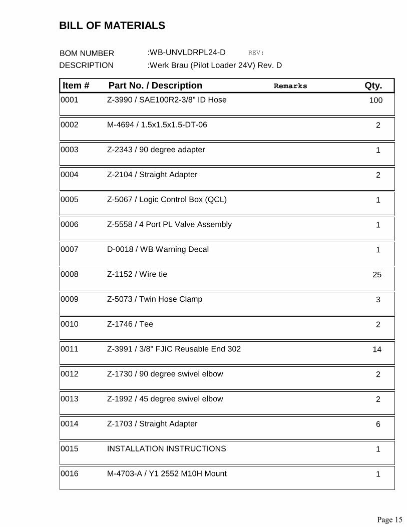
Item # Part No. / Description Qty.
BOM NUMBER :WB-UNVLDRPL24-D REV:
DESCRIPTION :Werk Brau (Pilot Loader 24V) Rev. D
Remarks
BILL OF MATERIALS
1000001 Z-3990 / SAE100R2-3/8" ID Hose
20002 M-4694 / 1.5x1.5x1.5-DT-06
10003 Z-2343 / 90 degree adapter
20004 Z-2104 / Straight Adapter
10005 Z-5067 / Logic Control Box (QCL)
10006 Z-5558 / 4 Port PL Valve Assembly
10007 D-0018 / WB Warning Decal
250008 Z-1152 / Wire tie
30009 Z-5073 / Twin Hose Clamp
20010 Z-1746 / Tee
140011 Z-3991 / 3/8" FJIC Reusable End 302
20012 Z-1730 / 90 degree swivel elbow
20013 Z-1992 / 45 degree swivel elbow
60014 Z-1703 / Straight Adapter
10015 INSTALLATION INSTRUCTIONS
10016 M-4703-A / Y1 2552 M10H Mount
Page 15

Item # Part No. / Description Qty.
BOM NUMBER :WB-UNVLDRPL24-D REV:
DESCRIPTION :Werk Brau (Pilot Loader 24V) Rev. D
Remarks
BILL OF MATERIALS
10017 M-4438 / WH-HE1-CB
10018 Z-5026 / Shipping Crate/No Runners
Page 16
Page 17
Page 18
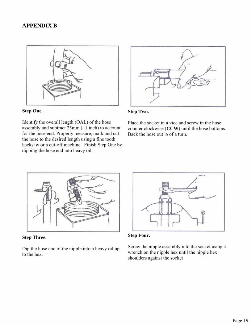
APPENDIX B
Step One. Identify the overall length (OAL) of the hose assembly and subtract 25mm (~1 inch) to account for the hose end. Properly measure, mark and cut the hose to the desired length using a fine tooth hacksaw or a cut-off machine. Finish Step One by dipping the hose end into heavy oil.
Step Two. Place the socket in a vice and screw in the hose counter clockwise (CCW) until the hose bottoms. Back the hose out ½ of a turn.
Step Three. Dip the hose end of the nipple into a heavy oil up to the hex.
Step Four. Screw the nipple assembly into the socket using a wrench on the nipple hex until the nipple hex shoulders against the socket
Page 19

Customer Feed Back Form
Rev. 051608
At WERK-BRAU we continually strive to provide the highest quality product. We feel there is no better opinion than that of the customer. This is why we ask that you take a few minutes to complete the form below and fax it back to us at 770-692-6978. Thank you for your time and effort in helping us provide the highest quality product possible.
Purchaser/User Kit Number:
Name WB- Address
Base Machine Make Model
Phone Serial Number Fax
Installation Time (hours) Customer Feedback
YES Comments: Did all components and/or parts fit well?
NO
YES Comments: Did the kit fit well overall? NO
YES Comments: Was the installation easy/simple?
NO
YES Comments: Were any modifications necessary?
NO
YES Comments: Were the instructions clear and concise?
NO
YES Comments: Were the drawings clear and concise? NO
Comments: Do you have any suggestions to improve the installation of this kit?
Page 20
Top Related